

Page 1
WARRANTY
Great Planes®Model Manufacturing Co.
guarantees this kit to be free from defects in both material and workmanship at the date of purchase. This
warranty does not cover any component parts damaged by use or modification.In no case shall Great Planes’liability exceed the original cost of
the purchased kit. Further, Great Planes reserves the right to change or modify this warranty without notice.
In that Great Planes has no control over the final assembly or material used for final assembly, no liability shall be assumed nor accepted for any
damage resulting from the use by the user of the final user-assembled product.By the act of using the user-assembled product, the user accepts all
resulting liability.
If the buyer is not prepared to accept the liability associated with the use of this product, the buyer is advised to return this kit immediately
in new and unused condition to the place of purchase.
To make a warranty claim send the defective part or item to Hobby Services at the address below:
Hobby Services
3002 N. Apollo Dr., Suite 1
Champaign IL 61822
USA
Include a letter stating your name, return shipping address, as much contact information as possible (daytime telephone number, fax number, e-mail
address), a detailed description of the problem and a photocopy of the purchase receipt.Upon receipt of the package the problem will be evaluated
as quickly as possible.
READ THROUGH THIS MANUAL BEFORE STARTING
CONSTRUCTION.IT CONT AINS IMPOR T ANT INSTRUCTIONS
AND WARNINGS CONCERNING THE ASSEMBLY AND
USE OF THIS MODEL.
GPMZ0204 for GPMA1303 V1.1 Entire Contents © Copyright 2006
Champaign, IL
(217) 398-8970, Ext. 5
airsupport@greatplanes.com
INSTRUCTION MANUAL
Wingspan: 81 in [2060mm]
Wing Area: 1000 sq in [64.5 dm
2
]
Weight: 13-14 lb [5900–6350g]
Wing Loading: 29–32oz/sq ft [88–98g/dm
2
]
Length: 62.5 in [1590mm]
Radio: 6-channel with seven servos
Engine: .91 – 1.08 cu in [15–17.5cc] two-stroke or
1.20 cu in [20cc] four-stroke engine
Manufactured under license by Pennzoil-Quaker State Company,
2004; Hobbico, Inc. P.O.Box 9021 Champaign, IL 61826-9021
®
Page 2
INTRODUCTION.................................................................................2
AMA....................................................................................................2
IMAA...................................................................................................2
SCALE COMPETITION......................................................................3
SAFETY PRECAUTIONS...................................................................3
ITEMS REQUIRED.............................................................................3
Hardware & Accessories .............................................................3
Adhesives & Building Supplies....................................................4
Optional Supplies & Tools ...........................................................4
IMPORTANT BUILDING NOTES.......................................................4
ORDERING REPLACEMENT PARTS ...............................................5
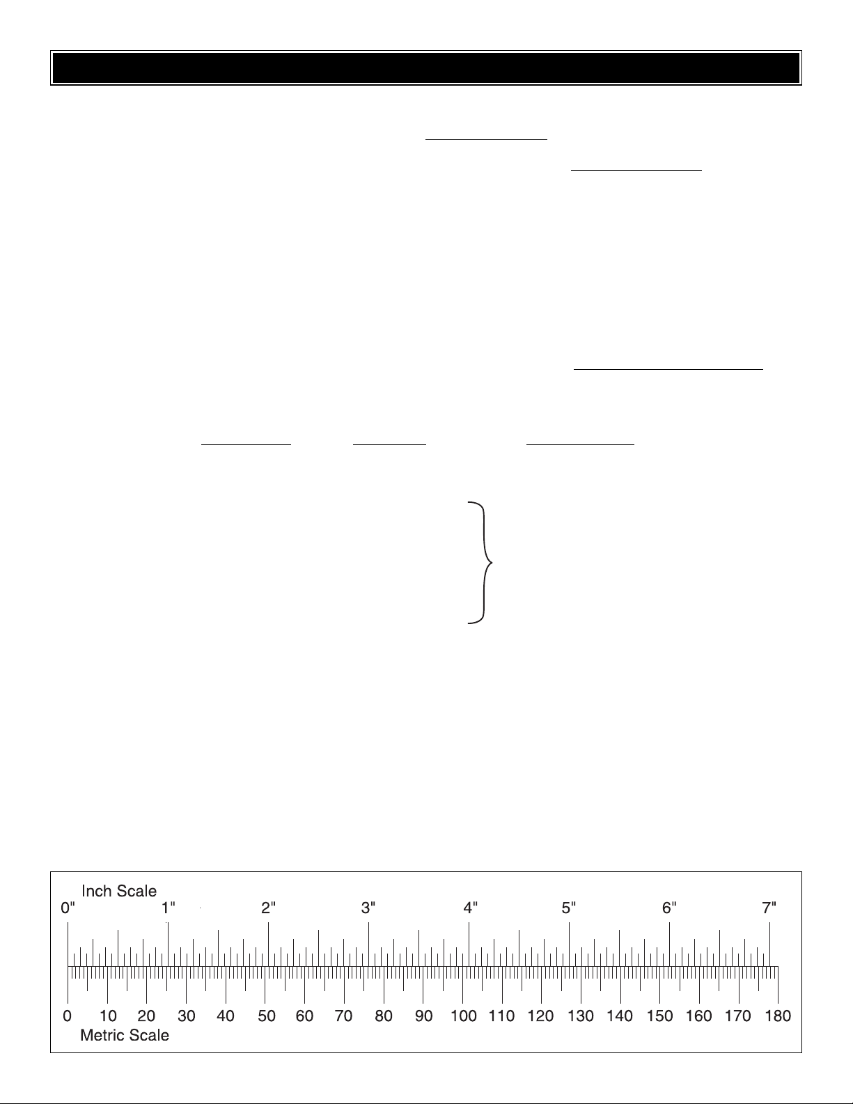
METRIC/INCH RULER.......................................................................5
KIT CONTENTS .................................................................................6
PREPARATIONS................................................................................7
ASSEMBLE THE WING .....................................................................7
Install the Ailerons .......................................................................7
Install the Aileron Servos & Pushrods ........................................8
Assemble the Wing Center-Section..........................................10
Install the Landing Gear, Wheels & Wheel Pants .....................11
ASSEMBLE THE FUSELAGE..........................................................13
Install the Stab, Elevators & Rudder.........................................13
Install the Engine, Fuel Tank & Throttle Servo ..........................14
Mount the Cowl.........................................................................16
Install the Radio System, Purshrods, Control Horns & Tail Wheel........18
Install the Receiver & Battery....................................................21
FINISHING TOUCHES......................................................................21
Apply the Decals.......................................................................22
GET THE MODEL READY TO FLY..................................................22
Check the Control Directions ....................................................22
Set the Control Throws..............................................................23
Balance the Model (C.G.)..........................................................23
Balance the Model Laterally......................................................24
PREFLIGHT......................................................................................24
Identify Y our Model....................................................................24
Charge the Batteries.................................................................24
Balance the Propellers..............................................................24
Ground Check...........................................................................24
Range Check.............................................................................24
ENGINE SAFETY PRECAUTIONS..................................................25
AMA SAFETY CODE (excerpt).......................................................25
IMAA SAFETY CODE (excerpt)......................................................26
CHECK LIST ....................................................................................27
FLYING .............................................................................................27
Fuel Mixture Adjustments..........................................................27
Takeoff.......................................................................................28
Flight..........................................................................................28
Landing......................................................................................28
ENGINE MOUNTING TEMPLATE....................................................28
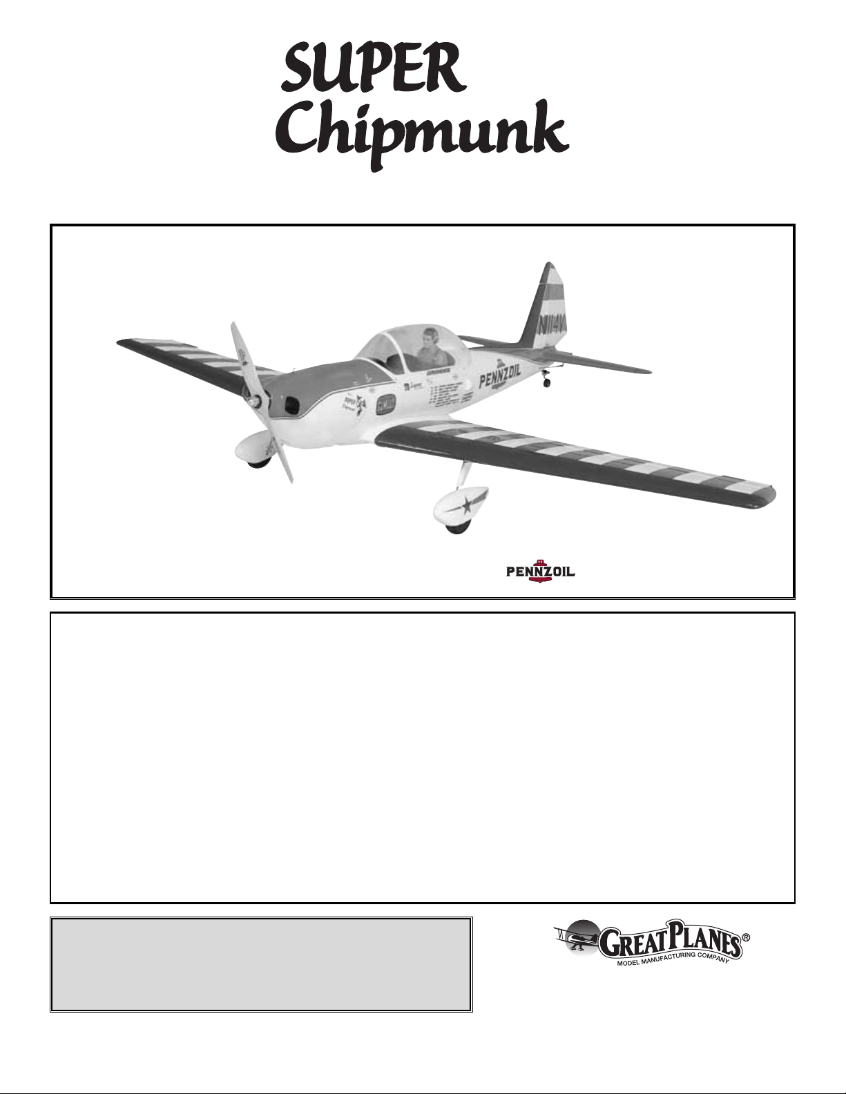
Thank you for your purchase of this aerobatic classic, Art
Scholl’s “Super Chipmunk!” We are proud of its great looks
and are sure that you will be proud to bring it to the field.The
fiberglass fuselage allows us to create a strong, goodlooking model that replicates the actual aircraft in great
detail.This airplane is capable of recreating all of the classic
air show maneuvers that Art performed for many years on
the air show circuit.We hope you enjoy the model as much
as we have enjoyed bringing it to you.
For the latest technical updates or manual corrections to the
Super Chipmunk 1.20 ARF, visit the Great Planes web site
at
www.greatplanes.com
. Open the “Airplanes” link, then
select the Super Chipmunk 1.20 ARF. If there is new
technical information or changes to this model a “tech
notice” box will appear in the upper left corner of the page.
We urge you to join the AMA (Academy of Model
Aeronautics) and a local R/C club. The AMA is the
governing body of model aviation and membership is
required to fly at AMA clubs. Though joining the AMA
provides many benefits, one of the primary reasons to join
is liability protection. Coverage is not limited to flying at
contests or on the club field.It ev en applies to flying at public
demonstrations and air shows. Failure to comply with the
Safety Code (excerpts printed in the back of the manual)
may endanger insurance coverage. Additionally, training
programs and instructors are available at AMA club sites to
help you get started the right way. There are over 2,500
AMA chartered clubs across the countr y. Contact the AMA
at the address or toll-free phone number below:
IMPORTANT!!! Tw o of the most important things you can do
to preserve the radio controlled aircraft hobby are to avoid
flying near full-scale aircraft and avoid flying near or over
groups of people.
The Great Planes Super Chipmunk 1.20 ARF is an excellent
sport-scale model and is eligible to fly in IMAA events.The
IMAA (International Miniature Aircraft Association) is an
organization that promotes non-competitive flying of giantscale models. If you plan to attend an IMAA event, obtain a
copy of the IMAA Safety Code b y contacting the IMAA at the
address or telephone number below, or by logging on to
their web site.
IMAA
205 S. Hilldale Road
Salina, KS 67401
(913) 823-5569
www.fly-imaa.org/imaa/sanction.html.
IMAA
Academy of Model Aeronautics
5151 East Memorial Drive
Muncie, IN 47302
Tele: (800) 435-9262
Fax (765) 741-0057
Or via the Internet at:
http://www
.modelaircraft.org
AMA
INTRODUCTION
TABLE OF CONTENTS
2
Page 3
Though the Great Planes Super Chipmunk 1.20 is an ARF
and may not have the same level of detail as an “all-out”
scratch-built competition model, it is a scale model
nonetheless and is therefore eligible to compete in the Fun
Scale class in AMA competition (we receive many favorable
reports of Great Planes ARFs in scale competition!). In Fun
Scale, the “builder of the model” rule does not apply. To
receive the five points for scale documentation, the only
proof required that a full-size aircraft of this type in this
paint/markings scheme did exist is a single sheet such as a
kit box cover from a plastic model, a photo, or a profile
painting, etc. If the photo is in black and white, other written
documentation of color must be provided. Contact the AMA
for a rule book with full details.
If you would like photos of the full-size Super Chipmunk for
scale documentation, or if you would like to study the photos
to add more scale details, photo packs are available from:
Bob’s Aircraft Documentation
3114 Y uk on Av e
Costa Mesa, CA 92626
Telephone: (714) 979-8058
Fax:(714) 979-7279
E-mail:
www.bobsairdoc.com
1.Your Super Chipmunk 1.20 ARF should not be considered
a toy, but rather a sophisticated, working model that
functions very much like a full-size airplane. Because of its
performance capabilities, the Super Chipmunk 1.20 ARF, if
not assembled and operated correctly, could possibly cause
injury to yourself or spectators and damage to property.
2. You must assemble the model according to the
instructions. Do not alter or modify the model, as doing so
may result in an unsafe or unflyable model. In a few cases
the instructions may differ slightly from the photos.In those
instances the written instructions should be considered
as correct.
3.You must take time to build straight, true and strong.
4. You must use an R/C radio system that is in first-class
condition, and a correctly sized engine and components
(fuel tank, wheels, etc.) throughout the building process.
5. You must correctly install all R/C and other components
so that the model operates correctly on the ground and in
the air.
6.You must check the operation of the model before every
flight to insure that all equipment is operating and that the
model has remained structurally sound. Be sure to check
clevises or other connectors often and replace them if they
show any signs of wear or fatigue.
7. If you are not an experienced pilot or have not flown this
type of model before, we recommend that you get the
assistance of an experienced pilot in your R/C club for your
first flights.If you’re not a member of a club, y our local hobby
shop has information about clubs in your area whose
membership includes experienced pilots.
8.While this kit has been flight tested to exceed normal use,
if the plane will be used for extremely high stress flying,
such as racing, the modeler is responsible for taking steps
to reinforce the high stress points.
9. WARNING:The cowl, fuselage and wheel pants included
in this kit are made of fiberglass, the fibers of which may
cause eye, skin and respiratory tract irritation. Never blow
into a part (wheel pant, cowl) to remove fiberglass dust, as
the dust will blow back into your eyes. Always wear safety
goggles, a particle mask and rubber gloves when grinding,
drilling and sanding fiberglass parts. Vacuum the parts and
the work area thoroughly after working with fiberglass parts.
Remember: Take your time and follow the instructions to
end up with a well-built model that is straight and true.
This is the list of hardware and accessories required to
finish the Great Planes Super Chipmunk 1.20 ARF. Order
numbers are provided in parentheses.
❏ .91 cu in [15cc] Two-stroke or 1.20 cu in [20cc] four-
stroke engine
❏ Propeller and spare propellers suitable for your engine
❏ 6-Channel radio
❏ Servos: (1) 35 oz-in servo (throttle), (5) 50 oz-in servos
(ailerons, flaps, elevator), (1) 80 oz-in servo (rudder)
❏ (2) – 2" [300mm] Servo extension (HCAM2711 for Futaba
®
)
❏ (2) – Y-harness (HCAM2751 for Futaba)
Hardware & Accessories
ITEMS REQUIRED
We, as the kit manufacturer, provide you with a top
quality, thoroughly tested kit and instructions, but
ultimately the quality and flyability of your finished model
depends on how you build it; therefore, we cannot in any
way guarantee the performance of your completed
model, and no representations are expressed or implied
as to the performance or safety of your completed model.
PRO TECT YOUR MODEL,Y OURSELF
& OTHERS...FOLLOW THESE
IMPORTANT SAFETY PRECAUTIONS
SCALE COMPETITION
3
Page 4
In addition to common household tools and hobby tools, this
is the “short list” of the most important items required to
build the Super Chipmunk ARF.
Great Planes Pro™CA and
Epoxy glue are recommended.
❏ 1/2 oz. [15g] Thin Pro CA (GPMR6001)
❏ 1 oz. [30g] Medium Pro CA+ (GPMR6008)
❏ Pro 30-minute epoxy (GPMR6047)
❏ Pro 6-minute epoxy (GPMR6045)
❏ Drill bits: 1/16" [1.6mm], 3/32" [2.4mm], 9/64" [3.6mm],
3/16" [4.8mm] and 7/32" [5.6mm].
❏ 8-32 tap and drill set (GPMR8103)
❏ Stick-on segmented lead weights (GPMQ4485)
❏ Silver solder w/flux (GPMR8070)
❏ Microballoons (TOPR1090)
❏ 3' [900mm] standard silicone fuel tubing (GPMQ4131)
❏ R/C foam rubber (1/4" [6mm] – HCAQ1000, or 1/2"
[13mm] – HCAQ1050)
Here is a list of optional tools mentioned in the manual that
will help you build the Super Chipmunk ARF.
❏ 4 oz. [113g] Aerosol CA activator (GPMR634)
❏ R/C-56 canopy glue (JOZR5007)
❏ CA applicator tips (HCAR3780)
❏ CA debonder (GPMR6039)
❏ Epoxy brushes (6, GPMR8060)
❏ Mixing sticks (50, GPMR8055)
❏ Mixing cups (GPMR8056)
❏ Curved-tip canopy scissors for trimming plastic parts
(HCAR0667)
❏ Threadlocker
™
thread locking cement (GPMR6060)
❏ Denatured alcohol (for epoxy clean up)
❏ Rotary tool such as Dremel
®
❏ Rotary tool reinforced cut-off wheel (GPMR8200)
❏ Servo horn drill (HCAR0698)
❏ Dead Center
™
Engine Mount Hole Locator (GPMR8130)
❏ AccuThrow
™
Deflection Gauge (GPMR2405)
❏ CG Machine
™
(GPMR2400)
❏ Precision Magnetic Prop Balancer
™
(TOPQ5700)
❏ 21st Century
®
sealing iron (COVR2700)
❏ 21st Century iron cover (COVR2702)
• There are two types of screws used in this kit:
Sheet metal screws are designated by a number and
a length. For example #6 x 3/4".
This is a number six screw that is 3/4" long.
Machine screws are designated by a number, threads per
inch, and a length – for example, 4-40 x 3/4". SHCS is just
an abbreviation for “socket head cap screw” and that is a
machine screw with a socket head.
This is a number four screw that is 3/4" long with forty
threads per inch.
• When you see the term
test fit
in the instructions, it
means that you should first position the part on the
assembly without using any glue, then slightly modify or
custom fit
the part as necessar y for the best fit.
• Whenever the term
glue
is written you should rely upon
your experience to decide what type of glue to use.When a
specific type of adhesive works best for that step, the
instructions will make a recommendation.
• Whenever just
epoxy
is specified you may use
either
30-minute (or 45-minute) epoxy or6-minute epoxy. When
30-minute epoxy is specified, it is highly recommended that
you use only 30-minute (or 45-minute) epoxy, because you
will need the working time and/or the additional strength.
•
Photos
and
sketches
are placed before the step they
refer to. Frequently you can study photos in following steps
to get another view of the same parts.
• The Super Chipmunk 1.20 ARF is factory-covered with
Top Flite®MonoKote®film. Should repairs ever be required,
MonoKote can be patched with additional MonoKote
purchased separately. MonoKote is packaged in six-foot rolls,
but some hobby shops also sell it by the foot. If only a small
piece of MonoKote is needed for a minor patch, perhaps a
fellow modeler would giv e you some.MonoKote is applied with
a model airplane covering iron, but in an emergency a regular
iron could be used. A roll of MonoKote includes full
instructions for application. Following are the colors used on
this model and order numbers for six foot rolls.
White – TOPQ0204
Missile Red – TOPQ0201
Sapphire Blue – TOPQ0226
• The stabilizer and wing incidences and engine thrust
angles have been factory-built into this model. However,
some technically-minded modelers may wish to check
these measurements anyway. To view this information visit
the web site at
www
.greatplanes
.com
and click on
“Technical Data.” Due to manufacturing tolerances which
will have little or no effect on the way your model will fly,
please expect slight deviations betw een your model and the
published values.
IMPORTANT BUILDING NOTES
Optional Supplies & Tools
Adhesives & Building Supplies
4
Page 5
5
Replacement parts for the Great Planes Super Chipmunk 1.20 ARF are available using the order numbers in the Replacement
Parts List that follows.The fastest, most economical service can be provided by your hobby dealer or mail-order company.
To locate a hobby dealer, visit the Great Planes web site at
www.g
reatplanes.com
. Choose “Where to Buy” at the middle of the
menu on the left side of the page. Follow the instructions provided on the page to locate a U.S., Canadian or International dealer. If a
hobby shop is not available, replacement parts may also be ordered from Tower Hobbies at
www.towerhobbies.com
, or by calling toll
free (800) 637-6050.
Parts may also be ordered directly from Hobby Services by calling (217) 398-0007, or via facsimile at (217) 398-7721, but full
retail prices and shipping and handling charges will apply. Illinois and Nevada residents will also be charged sales tax. If order ing via
fax, include a Visa
®
or MasterCard®number and expiration date for payment.
Mail parts orders and payments by personal check to:
Hobby Services
3002 N Apollo Drive, Suite 1
Champaign IL 61822
Be certain to specify the order number exactly as listed in the Replacement Parts List. Payment by credit card or personal check
only; no C.O.D.
If additional assistance is required for any reason contact Product Support by e-mail at
productsupport@greatplanes.com
, or by
telephone at (217) 398-8970.
Replacement Parts List
Or
der Number Description How to Purchase
Missing pieces.......................Contact Product Support
Instruction manual.................Contact Product Support
Full-size plans........................Not available
GPMA2480 Wing Kit
GPMA2481 Fuse Kit
GPMA2483 Tail Set
GPMA2482 Cowl
GPMA2485 Canopy
GPMA2486 Landing Gear
GPMA2484 Wheel Pants
GPMA2487 Tail Wheel
GPMA2488 Decal Set
ORDERING REPLACEMENT PARTS
................
Contact Your Hobby
Supplier to Purchase
These Items
To convert inches to millimeters, multiply inches by 25.4
Page 6
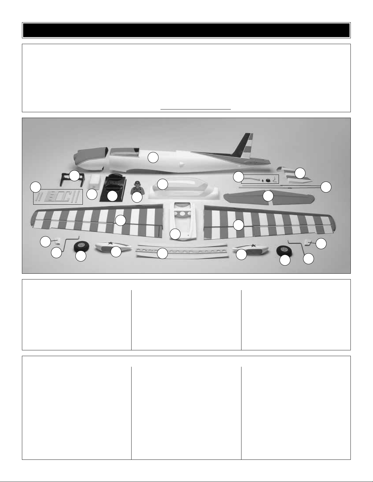
6
1. Fuselage
2. Engine Mount
3. Servo Tray Parts
4. Fuel Tank
5. Cockpit
6. Pilot
7. Canopy
8. Tail Wheel Assembly
9. Rudder
10. Stab Tubes
11. Stab & Elevators (L&R)
12. Left Wing Panel
13. Wing Center-Section
14. Right Wing Panel
15. Wire Covers
16. Landing Gear Wire
17. Wheels
18. Wheel Pants (L&R)
19. Wing Joiners (1-aluminum,
2-plywood)
Kit Contents (not photographed)
Kit Contents
(6) 4-40 Threaded Metal Clevis
(5) 4-40 Solder Clevis
(2) Screw-Lock Pushrod Connector
(8) 2-56 Threaded Metal Clevis
(6) 4-40 Nut
(4) 8-32 Blind Nuts
(8) 2-56 Nut
(4) 1/4-20 Blind Nut
(8) Large Nylon Control Horn
(2) 1/4-20 Nylon Bolt
(2) Nylon Retainer
(2) 2" x 9" Hinge Material
(1) 11-3/4" Gray Plastic Outer Tube
(7) 36" Gray Plastic Outer Tube
(17) Clevis Retainer
(6) 6-32 x 1/4" SHCS
(2) 4-40 x 1/4" SHCS
(2) #2 x 3/8" Sheet Metal Screw
(2) #4 x 3/8" Sheet Metal Screw
(4) 8-32 x 1-1/4" SHCS
(4) 8-32 x 1" SHCS
(48) #2 x 1/2" Sheet Metal Screw
(2) 3/16" Wheel Collar
(1) .074 x 12" Wire Threaded One End
(4) .095 x 5-3/4" Wire
(2) .095 x 48" Wire Threaded One End
(16) #2 Flat Washer
(8) #8 Lock Washer
(8) #8 Flat Washer
(8) Nylon Landing Gear Straps
(5) Nylon Anti-Rotation Pins
(4) Pull-Pull Wire (1020mm in length)
(8) 2-56 Threaded Brass Pull-Pull Connector
(8) Wire Crimp Connectors
(2) 3mm Plywood Wheel Pant Mounting Plate
(1) 152mm Velcro
®
(2) 6 x 13 x 36mm Hardwood Blocks
(4) 5mm Wheel Collar
(6) 3 x 5 x 5mm Plywood
(2) 1/4-20 Nylon Bolt (thumb screw type)
(4) Laser-Cut Plywood Parts (for the fiberglass
wire covers)
(2) 3 x 25 x 25mm Plywood Plate
Before starting to build, take an inventory of this kit to make sure it is complete, and inspect the parts to make sure they are of
acceptable quality. If any parts are missing or are not of acceptable quality, or if you need assistance with assembly, contact Product
Support. When reporting defective or missing parts, use the part names exactly as they are written in the Kit Contents list.
Great Planes Product Support:
3002 N Apollo Drive, Suite 1
Champaign, IL 61822
Telephone: (217) 398-8970, ext. 5
Fax:(217) 398-7721
E-mail:
airsupport@g
reatplanes.com
KIT CONTENTS
1
2
4
5
7
6
13
19
12
11
15
16
17
18
15
16
17
18
14
3
8
9
10
Page 7
❏ 1. If you have not done so already, remove the major
parts of the kit from the box and inspect for damage. If any
parts are damaged or missing, contact Product Suppor t at
the address or telephone number listed in the
“Kit
Contents”
section on page 6.
❏ 2. Remove the tape and separate the ailerons and flaps
from the wing and the elevators from the stab. Use a
covering iron with a covering sock on high heat to tighten
the covering if necessary. Apply pressure over sheeted
areas to thoroughly bond the covering to the wood.
Do the right wing panel first so your work matches the
photos the first time through
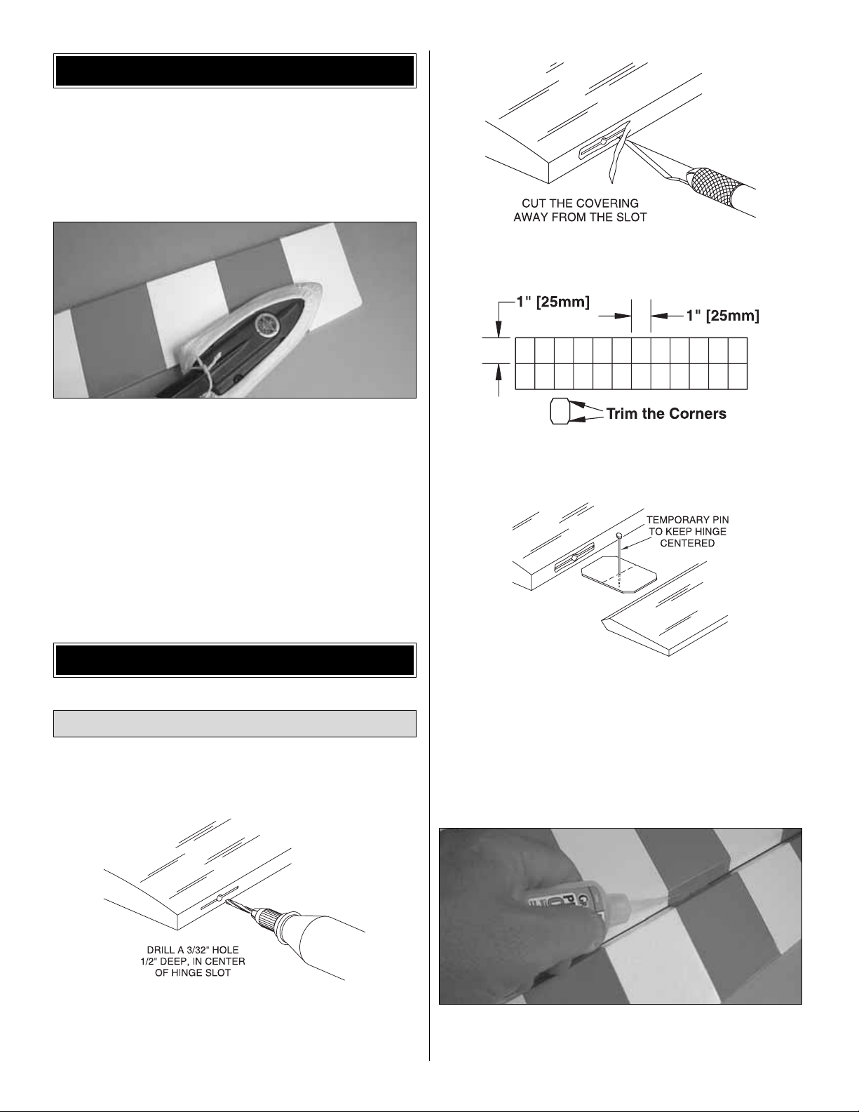
❏ ❏ 1. Drill a 3/32" hole, 1/2" [13mm] deep in the center
of each hinge slot to allow the CA to “wick”in. Follow-up with
a #11 blade to clean out the slots.Hint: If you hav e one, use
a high-speed rotary tool to drill the holes.
❏ ❏ 2. Use a shar p #11 blade to cut a strip of covering
from the hinge slots in the wing and aileron.
❏ ❏ 3. Cut fourteen 1" x 1" [25 x 25mm] hinges from the
CA hinge strip. Snip off the corners so they go in easier.
❏ ❏ 4.T est fit the right aileron to the wing with f our hinges .
If the hinges don’t remain centered, stick a pin through the
middle of the hinge to hold it in position.
❏ ❏ 5. Remove any pins you may have inserted into the
hinges. Adjust the aileron so there is a small gap between the
LE of the aileron and the wing. The gap should be small, just
enough to see light through or to slip a piece of paper through.
❏ ❏ 6. Apply six drops of thin CA to the top and bottom of
each hinge. Do not use CA accelerator. After the CA has
fully hardened, test the hinges by pulling on the aileron.
Install the Ailerons
ASSEMBLE THE WING
PREPARATIONS
7
Page 8
❏ ❏ 7.Test fit the r ight flap to the wing with three hinges.
Using the same procedure used for the ailerons, join the
flaps to the wing.
8. Repeat steps 1- 7 for the left wing panel.
❏ ❏ 1. Install a 12" [305mm] servo extension onto the
aileron servo lead. Secure the extension to the lead with
tape, a piece of shrink tube or some other method to keep
them from coming unplugged.
❏ ❏ 2. Cut the covering away from the aileron and flap
servo openings in the bottom of the wing.
❏ ❏ 3.Taped inside the aileron ser vo opening is a string.
Taped inside the flap opening is the other end of the string.
Tie the aileron servo extension to the string in the aileron
servo opening.Tie the flap servo lead to the string in the flap
opening. Pull the two ser vo leads through the wing with the
string that is taped to the root rib. Untie the string from the
leads and tape the leads to the wing root to prevent them
from falling back into the wing.
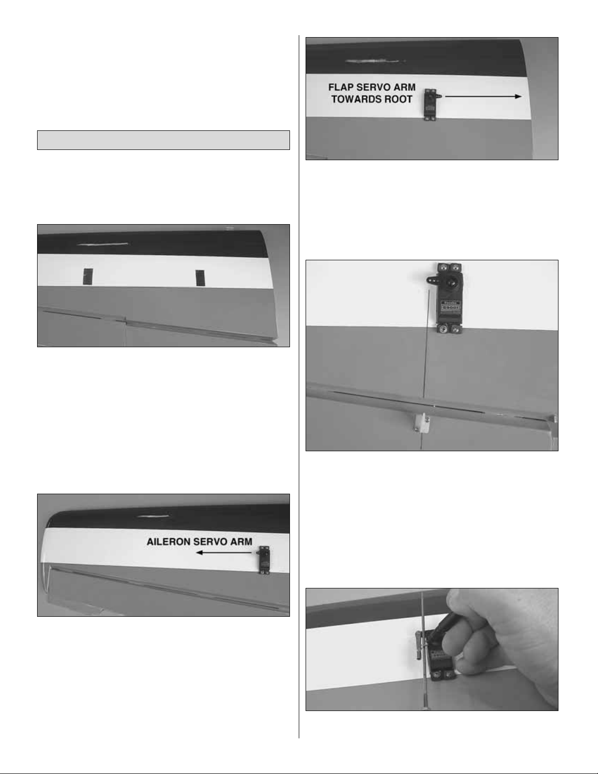
❏ ❏ 4. Install the aileron servo into the aileron servo
opening.Drill through the servo mounting holes with a 1/16"
[1.6mm] drill bit. Remove the servo from the servo opening.
Install and then remove a servo mounting screw into each of
the holes you have drilled. Apply a drop of thin CA into the
holes to harden the threads. Once the glue has hardened
install the servo into the servo opening using the hardware
included with your servo. Center the servo, then install a
servo arm as shown. The arm should be pointing towards
the wing tip.
❏ ❏ 5. Install the flap ser vo into the flap servo opening,
mounting it using the same procedure for the aileron servo.
Install the servo arm onto the flap servo with the arm
pointing towards the root rib. Important! When instructed to
do the left wing, the arm on the flap servo must point
towards the left wing tip, not the root rib as was done on the
right wing panel.
❏ ❏ 6. Place a nylon control horn in line with the last hole
in the servo arm. When positioned properly the control horn
will rest on a hardwood plate in the aileron. Mark the
location of the mounting holes onto the aileron. Drill a 1/16"
[1.6mm] hole on the marks, drilling through the plywood
plate but not through the top of the aileron. Insert and
remove a #2 x3/8" [10mm] screw into each of the holes.
Apply a couple drops of thin CA into the holes to harden the
threads. Once the glue has hardened attach the control
horn to the aileron with two #2 x 3/8" [10mm] screws.
❏ ❏ 7. Screw a 4-40 nut onto a 4-40 x 5-3/4" [146mm]
threaded rod approximately twenty turns. Slide a silicone
Install the Aileron Servos & Pushrods
8
Page 9
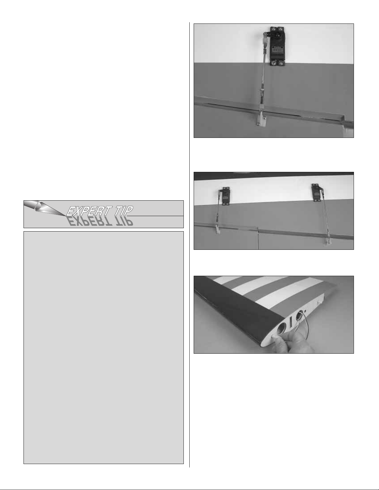
clevis retainer onto a threaded 4-40 metal clevis and then
screw the clevis onto the rod, tightening it against the nut.
Install the clevis onto the nylon control horn. Install an
unthreaded clevis onto the servo arm. Center the aileron.
Then, mark the threaded rod where it should be cut to fit the
clevis. Remove all of the pushrod components from the
servo and control horn. Read the
Expert Tip
that follows.
Then, silver solder the clevis to the pushrod.
❏ ❏ 8. After the rod has cooled, install a clevis retainer
onto the clevis you have just soldered. Then, install the
pushrod onto the aileron and servo.
❏ ❏ 9.Using the same method, install the pushrod linkage
to the flap.
❏ ❏ 10.Using 6-minute epoxy, glue two nylon anti-rotation
pins into the holes in the root of the wing. Each one should
extend from the wing approximately 1/2" [13mm].
❏ 11. Repeat steps 1-9 for the left wing panel.
HOW T O SOLDER
1. Use denatured alcohol or other solvent to thoroughly
clean the pushrod. Use coarse sandpaper to roughen the
end of the pushrod where it is to be soldered.
2. Apply a few drops of soldering flux to the end of the
pushrod, then use a soldering iron or a torch to heat it.Tin
the heated area with silver solder (GPMR8070) by
applying the solder to the end. The heat of the pushrod
should melt the solder-not the flame of the torch or
soldering iron-thus allowing the solder to flow.The end of
the wire should be coated with solder all the way around.
3.Place the clevis on the end of the pushrod.Add another
drop of flux, then simultaneously heat the clevis and
pushrod. Slide the clevis the rest of the way onto the
pushrod as the solder melts.Apply another small amount
of solder while the pushrod and clevis are still hot. The
same as before, the heat of the parts being soldered
should melt the solder, thus allowing it to flow. Allow the
joint to cool naturally without disturbing. Avoid excess
blobs, but make certain the joint is thoroughly soldered.
The solder should be shiny, not rough. If necessary,
reheat the joint and allow to cool.
4. Immediately after the solder has solidified, but while it
is still hot, carefully use a cloth to quickly wipe off the flux
before it hardens. Important: After the joint cools, coat
with oil to prevent rust.Note: Do not use the acid flux that
comes with silver solder for electrical soldering.
9
Page 10
Did you know…Between 1969 and 1985 Art Scholl
performed in a total of 1,345 airshows in the U.S .A., Canada
and Japan!
❏ 1. Before beginning this step be sure you have plenty of
clamps to assure that the plywood is securely bonded to the
aluminum. Locate the aluminum wing joiner and two 1/8"
[3mm] plywood wing joiners. Using 30-minute epoxy, glue
the plywood to both sides of the aluminum to form the wing
joiner using denatured alcohol and a paper towel, clean any
excess epoxy from the joiner before the glue hardens. After
the glue fully hardens, test fit the joiner into each wing and
the wing center-section. Sand the joiners as needed for a
good fit between the wing halves and the joiner.
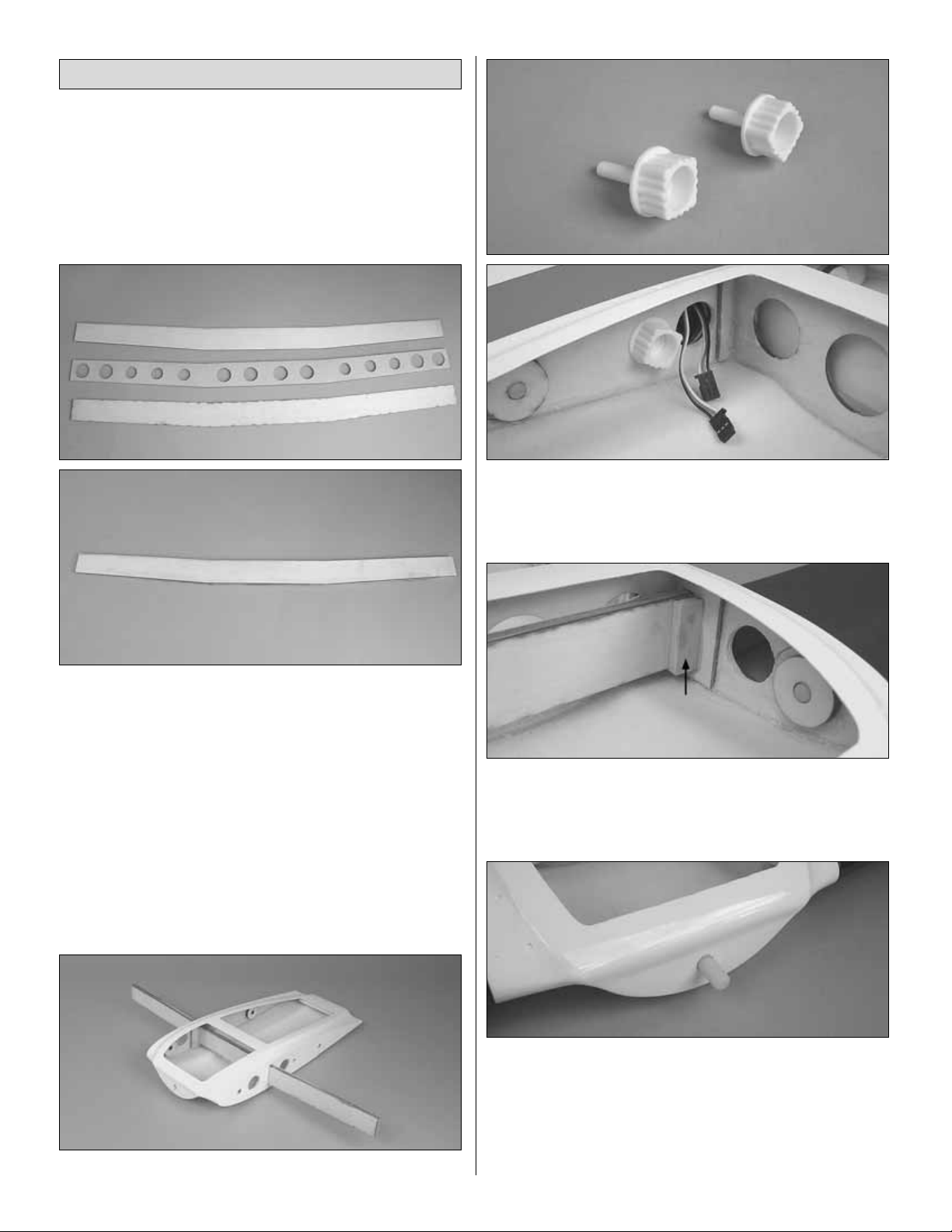
❏ 2. Center the joiner in the wing center-section.
❏ 3. Slide both wing halves onto the joiner, pushing the
wings tight against the wing center-section. Locate two
1/4-20 wing bolts with the knurled head and screw them into
the wing and the wing center-section.Do this for both wings.
❏ 4. Once you are satisfied with the fit of the wings to the
wing center-section, glue a 1/4" x 1/2" x 1-1/2" [6 x 13 x 38mm]
hardwood block to the joiner and the wing center-section at
both sides of the center-section.
❏ 5. Using 6-minute epoxy, glue the remaining nylon wing
dowel into the leading edge of the wing center-section.The
dowel should extend approximately 1/2" [13mm] from the
front of the wing center.
The method we have designed for the wing assembly gives
you the flexibility of leaving the wing together as a one piece
Assemble the Wing Center-Section
10
Page 11

wing or you can disassemble it into two or even three pieces
for easier transportation. If you choose to leave the wing
together as a one piece wing, it is recommended that you
regularly check the nylon screws to be sure they remain tight.
❏ 1. Cut the covering away from the landing gear wire slot
in the bottom of each wing.
❏ 2. Install the landing gear wire in the wing as shown.
Mount the wire to the wing with two nylon landing gear
straps. Drill four 1/16" [1.6mm] holes into the hardwood
landing gear blocks. Inser t and remove a #2 x 1/2" [13mm]
screw into each of the holes. Apply a couple drops of thin
CA into the holes to harden the threads and allow the glue
to harden. Install the landing gear wire to the wing with the
screws and landing gear straps.Do this for both wings.
❏ 3.Drill a 3/16" [4.8mm] hole into each of the wheel pants
as shown.
❏ 4. Inside the wheel pant, roughen the fiberglass along
each side of the molded slot with 80-grit sandpaper. Clean
the area well with denatured alcohol. Using 6-minute epoxy,
glue the plywood wheel pant doubler inside the wheel pant
as shown. Allow the glue to harden before proceeding. Do
this for both wheel pants.
❏ 5.Apply 6-minute epoxy on one side of the plywood axle
doubler. Slide the doubler onto the axle. Push the axle
completely into the wheel pant, aligning the axle
perpendicular to the side of the wheel opening. Use small
clamps to hold the doubler in place to the wheel pant until
the glue hardens.
❏ 6. File a flat spot onto the end of each axle for the wheel
collar set screw.
Install the Landing Gear,Wheels
& Wheel Pants
11
Page 12

❏ 7.Install a 6-32 x 1/4" [6mm] socket head cap screw into
each of the 3/16" [4.8mm] wheel collars. Install the wheel
pant, a 3/16" wheel collar, the wheel and another 3/16"
wheel collar onto the axle. Center the wheel in the wheel
pant, apply thread locker to the set screw and then tighten
the wheel collar set screws.
You will find the following steps easier if you remove
the landing gear from the wing.
❏ 8. The landing gear fairing consists of two laser-cut
plywood formers and the fiberglass fairing. Glue the large
former to the wide end of the fairing and the small former to
the narrow end of the fairing with CA.
❏ 9.Slide the fairing onto the landing gear wire, positioning
the bottom of the fairing slightly below the top of the wheel
pant. Mark the location of the fairing on the wire, then
remove the fairing. Roughen the wire in the area of the
fairing with 80-grit sandpaper.Re-install the fairing onto the
wire, making sure it is properly positioned to the wheel pant
and that the front of the fairing is aligned with the front of the
pant. Apply CA to the formers to tack them to the wire.
❏ 10.Mix a small amount of 6-minute epoxy with microballoon
filler. Liberally apply the mixture to the former and the
landing gear wire. Do this for both the formers. Allow the
glue to harden.
❏ 11. Apply a small amount of medium CA to the trailing
edge of the fairing. Squeeze the trailing edge of the fairing
together, holding it until the glue hardens.Once the glue has
hardened apply a mixture of epoxy and microballoons to the
inside of the trailing edge to give a more secure joint.
12
Page 13

❏ 12. Re-install the landing gear to the wing. You should
have been doing both of the landing gear but if you have
only completed one, go back and do the remaining one.
Did you know…It was not uncommon for Art to fly with his
dog named “Aileron!”
❏ We have included a handy fuselage stand that easily
installs to the fuselage with two 1/4 -20 nylon wing bolts.Y ou
will find it useful when working with the model on your work
bench as well as for transporting the model to the field.
During the assembly of the fuselage it will be useful while
installing the stab and elevators as well as the engine and
the cowl. Feel free to use it throughout the remaining steps
of the building process as needed.
❏ 1. Temporarily install the stab halves onto the aluminum
stab joiner tubes. Insert three hinges into the slots in each
half of the stab. Note: The inboard hinges can only be
inserted until they make contact with the stab joiner tube in
the stab. The outboard hinge should be positioned with a
T-pin to keep it centered.
❏ 2.Examine the elevators.Notice that a hardwood plate is
located on one side of both elevators. This is the bottom of
the elevator. Install the elevators to the stab using the same
procedure used for mounting the ailerons to the wing.
Install the Stab, Elevators & Rudder
ASSEMBLE THE FUSELAGE
13
Page 14

❏ 3.Roughen the stab fairing as shown with 80-grit sandpaper.
❏ 4. Apply 6-minute epoxy to the stab fairing where you have
roughened the surface and to the root rib of the stab.Slide the
stab and stab joiner tubes into the fuselage, pressing the stab
firmly to the fuselage. Clean any excess epoxy with rubbing
alcohol and a paper towel.Apply masking tape to hold the stab
in place until the glue has hardened.Important! When installing
the stab, be sure the plywood plates on the elevator are on the
bottom of the plane.
❏ 5. Hinge the rudder to the vertical fin using the same
technique used on the ailerons and elevators.
❏ 1. Cut the engine template from page 29 of the
instruction manual. Tape the template onto the firewall
aligning the dashed lines of the template with lines molded
on the firewall.
❏ 2. Drill 7/32" [5.6mm] holes through the firewall at each
of the drilling locations on the template. Install four 8-32
blind nuts into the backside of the firewall. This is easily
done by reaching into the fuselage, holding the blind nut
over the hole you drilled, and then using a 8-32 x1" [25mm]
socket head cap screw and #8 washer from your hardware
to pull the blind nut into the hole.
❏ 3. Cut the tabs from the engine mount. Attach it to the
firewall with four 8-32 x 1-1/4" [32mm] socket head cap
screws, #8 lock washers and #8 flat washers. Before
tightening the bolts, set the engine on the mounting rails and
adjust them to fit the engine.Then, tighten the bolts.
❏ 4.Position the engine on the mount so the distance from
the firewall to the front of the thrust washer measures 6-3/8"
[162mm]. Mark the location of the engine on the mount.The
Install the Engine, Fuel Tank &
Throttle Servo
14
Page 15

Great Planes “Dead Center™” Hole Locator (GPMR8130)
works well for this. Dr ill through the marks you have made
with a #29 or 9/64" [3.6mm] drill bit. Tap each hole with an
8-32 tap.
❏ 5. Install the engine to the mount with four each, 8-32 x
1" [25mm] socket head cap screws , #8 lock washers and #8
flat washers.
❏ 6. Dr ill a 3/16" [4.8mm] hole through the firewall in-line
with the throttle arm on the carburetor.
❏ 7. Locate the 12" [305mm] gray plastic pushrod tube.
Sand one end of the tube with 220-grit sandpaper.Insert the
tube into the firewall and glue the roughened end of the tube
flush to the firewall.
❏ 8. Assemble the fuel tank as shown in the sketch.When
tightening the center screw be sure not to overtighten it.You
just want it snug enough to pull the rubber stopper tight
against the tank.
❏ 9. Install silicone fuel tubing (not supplied) onto the
aluminum tubes from the fuel tank. The line with the fuel
clunk will feed to the fuel inlet at the needle valve and the
other will attach to the pressure tap on the muffler. If you
choose to use some kind of an external fuel valve follow the
instructions with your particular brand of fuel valve.You can
also install a third line to the tank and use it for filling the
tank. The method you use is your choice but make your
decision before moving onto the installation of the fuel tank.
❏ 10. Install the tank into the fuselage with the neck of the
tank through the firewall.
❏ 11. Locate and glue two 1/8" x 3/8" x 7-3/8" [3 x 9.5 x
187mm] plywood sticks and glue them to the balsa
longerons inside the fuselage with 6-minute epoxy.
❏ 12. Glue two 1/8" x 3/8" 5-1/4" [3 x 9.5 x 133mm] plywood
doublers to the plywood servo tray.
❏ 13. Install the 1/8" [3mm] plywood servo tray into the
fuselage, making sure the doublers you glued in are facing
the top of the fuselage. Position it on the longerons on the
sides of the fuselage and far enough forw ard to hold the fuel
tank securely in place. Drill six 1/16" [1.6mm] holes in the
tray and longeron.Secure the tray in place with six #2 x 1/2"
[13mm] screws and #2 washers.
15
Page 16

❏ 14. Place your throttle servo into the servo tray as
shown. Drill a 1/16" [1.6mm] hole through each of the
mounting holes. Remove the servo, then install and remove
a servo mounting screw into each hole. Apply a couple
drops of thin CA into the holes to harden the threads.When
the glue has hardened, permanently mount the servo to the
servo tray. Cut the plastic throttle tube as shown.
❏ 15. Cut the 1" [25mm] threaded end from the .074 x 12"
[305mm] throttle pushrod wire. Install the wire into the tube
and attach it to the servo horn and the throttle arm on the
carburetor with two brass screw-lock connectors, the nylon
retainer and a 4-40 x 1/4" [6mm] socket head cap screw.
❏ 1. Slide the cowl onto the fuselage and over the engine
as far as you can. Mark the location where the engine
begins to make contact with the cowl. Begin cutting the
fiberglass cowl using a high-speed rotary tool. Hint: If you
are using a four-stroke engine you can remove the valve
cover , allo wing more room when fitting the engine.Cut small
amounts away from the cowl at a time, making adjustments
as needed until the cowl fits over the engine.
❏ 2. Locate three balsa cowl rings. Glue them together to
form one 3/8" [9.5mm] cowl ring.
❏ 3. Located on both sides of the fuselage is a small
dimple. This dimple is a reference for the plywood block
inside of the fuselage for the cowl mounting screws.Apply a
Mount the Cowl
16
Page 17

2-1/2" [64mm] piece of masking tape over the dimple and to
the side of the fuselage as shown. Do this on both sides of
the fuselage. Using a fine-tip felt pen, mark the dimple and
draw a line back from the dimple 2" [51mm].
❏ 4. Install the cowl to the fuselage. Insert the cowl ring
onto the engine and the front of the cowl. Note: The cowl
ring is a useful tool for centering the engine to the opening
in the front of the cowl. It has been made to fit the O.S.
®
1.20. If you are using another engine it may or may not fit.
You may choose to make a ring to fit your engine or you can
center the engine without using the ring.
❏ 5. Place the propeller onto the engine. Position the cowl
so that there is 1/8" [3mm] clearance between the cowl and
the propeller.Note: If you are planning to use some form of
a spinner, be sure you fit the cowl to the spinner backplate
instead of the propeller.
❏ 6.With the cowl aligned to the fuselage sides, measure
forward 2" [51mm] from the reference mark you made on
the masking tape.Drill a 1/16" [1.6mm] hole though the cowl
and fuselage. Temporarily install a #2 x 1/2" [13mm] screw
into the cowl to hold it in position on the fuselage. Repeat
this step for the other side of the cowl.
❏ 7.Drill a 1/16" [1.6mm] hole through the bottom cowl and
the fuselage as shown. Do this on both sides of the cowl.
Install a #2 x 1/2" [13mm] screw into the cowl and fuselage.
The screw exits out of the fuselage into the low er opening in
the fuselage.
❏ 8. Back the screw out until it is no longer visible in the
opening of the fuselage. Glue a 1/8" x 1" x 1" [3 x 25 x 25mm]
plywood plate over the hole. After the glue has hardened
17
Page 18

re-install the screw, screwing it into the hardwood. Be sure to
fuelproof the wood plates with epoxy or a good fuelproof paint.
❏ 9. Cut out any other portions of the cowl as needed for
the needle valve, glow driver, muffler, etc.When positioning
the muffler it is important that the muffler exhaust not be
pointing directly at the fiberglass fuselage.The heat from the
muffler will discolor the fiberglass. For our model we
installed a muffler header from O.S. that allows additional
flexibility for positioning the muffler (O.S. Exhaust Header
Pipe OSMG2623). You can use this, route the muffler
directly out the side of the cowl or consider the silicone
diverters available f or many engines .When you are finished,
put a couple of drops of thin CA into the cowl mounting
holes you drilled in the fuselage to harden the threads.
Install the cowl to the fuselage with #2 screws and #2
flat washers.
Did you know…Art flew airplanes for many well-known
movies and T.V. shows. The Great Waldo Pepper, Baa Baa
Black Sheep, Indiana Jones and the Temple of Doom and
Top Gun just to name a few!
❏ 1. Locate two .095 x 48" [1220mm] pushrod wires. Install a
4-40 nut, 4-40 threaded metal clevis and silicone cle vis retainer
onto the threaded end of each wire. Install the clevis in the
second hole from the end of a large nylon control horn. Cut
6-1/2" [165mm] from the unthreaded end of the wires.
❏ 2. Install the pushrod wires into the guide tubes on each
side of the fuselage.Position the control horn as shown.Drill
a 1/16" [1.6mm] hole into the plywood plate on each
elevator for the control horns. Do not drill through the
elevator, only the plywood plate! Install and then remove a
#2 x 1/2" [13mm] screw into each of the holes you drilled.
Apply a couple of drops of thin CA into the holes to harden
the threads. Once the glue has hardened, install the control
horns to the elevators with the screws.
Refer to this photo for the following two steps.
❏ 3.Install a 6-32 x 1/4" [6mm] socket head cap screw into
two 3/16" [4.8mm] wheel collars, then slide the wheel collars
over both elevator pushrod wires.
Install the Radio System, Pushrods,
Control Horns & Tail Wheel
18
Page 19

❏ 4.Place your elevator servo into the servo tra y as shown,
positioning the last hole of the servo arm over the pushrod
wire. Drill a 1/16" [1.6mm] hole through each of the
mounting holes. Remove the servo, then install and remove
a servo mounting screw into each hole. Apply a couple
drops of thin CA into the holes to harden the threads.When
the glue has hardened, permanently mount the servo to the
servo tray with the hardware provided with your servo.
❏ 5. Center the elevator servo. Install a 4-40 solder clevis
onto the servo arm. Center both halves of the elevator. On
the wire closest to the servo, mark the cut location for the
wire to fit the clevis. Cut the wire on that mark. Cut the
remaining wire 1" [25mm] shorter.
❏ 6. Solder the clevis to the wire closest to the servo.Slide
a clevis retainer ov er the servo .Then, attach the clevis to the
servo arm.With the elev ator servo centered and both halves
of the elevator centered, tighten the soc ket head cap scre ws
securely to the pushrod wires.
❏ 7. Install a two-arm servo arm onto the 80 oz-in rudder
servo, then install the rudder servo as shown using the
same technique used on other servos.
❏ 8.Install a nylon control horn on both sides of the rudder
with #2 x 1/2" [13mm] screws in the same way you installed
the elevator horns.
❏ 9. Slide a copper crimp connector onto one of the coils of
pull-pull wire followed by a threaded brass pull-pull connector.
❏ 10. Loop the wire back through the crimp connector and
crimp the connector onto the wire with pliers.
❏ 11. Screw a 2-56 nut onto the end of the threaded brass
pull-pull connector followed by a 2-56 clevis and a silicone
clevis retainer.
19
Page 20

❏ 12. Install a wire to each end of the r udder servo arm.
Feed the wire through the outer two tubes until they exit the
fuselage near the rudder.
❏ 13. Put together two more sets of threaded brass pull-
pull connectors, clevises and clevis retainers. Install them
into the rudder control horns, one hole in from the end of the
horn. Center the rudder servo and the rudder. Install the
crimp connector onto the wire. Feed the wire through the
connector and back into the crimp connector. Be sure you
have equal tension on both wires, and then crimp the
connector onto the wires with pliers.Adjustment to the wires
can be made by threading the brass connector into or out of
the clevis.Once adjusted, tighten the nut against the clevis.
❏ 14. Install the tail wheel and wheel collars to the tail
wheel wire as shown. File a flat spot on the wire for the set
screw in the control arm.
❏ 15.On the bottom of the fuselage is a flat area.Place the tail
wheel assembly on this portion of the fuselage and mark the
location of the mounting holes.Drill a 3/32 [2.4mm] hole through
the fuselage on the marks. Insert and remove a #4 x 3/8"
[9.5mm] screw. Apply a couple of drops of thin CA in the holes
to harden the threads. After the glue has hardened mount the
tail wheel bracket with two #4 x 3/8" [9.5mm] screws.
20
Page 21

❏ 16. Assemble another pair of pull-pull wires for the tail
wheel just as you did for the rudder .Install them on the inner
holes of the rudder servo arm and into the outer holes on
the tail wheel arm.
❏ 1. Install the strip of hook-and-loop mater ial through the
slots in the servo tray to hold the receiver in place .Place the
receiver on 1/4" [6mm] foam. Then, tighten the hook-andloop material around the receiver.
❏ 2.Use an arm cut from a servo horn to make an antenna
strain relief as shown. Insert the receiver antenna into the
antenna tube. Hold it in by placing a small rubber band
around the tail wheel and the end of the antenna.
❏ 3. Place the batter y on a piece of 1/4" [6mm] foam and
strap it to the former above the fuel tank with a couple of #64
rubber bands.
❏ 4. Install a switch harness and charge jack to the fuselage.
Connect the switch to the battery. Be sure to use heat shrink
or tape to be sure the battery to switch connection is secure.
❏ 5.Plug the servos into the receiver .Make adjustments to
the position of the servo arms as needed.
Did you know…Art Scholl had three different Chipmunks.
The version that Great Planes has chosen was his third,
which he purchased in May 1977.Originally, N1114V did not
carry the color scheme replicated here.You can still see this
Chipmunk at the EAA Museum in Oshkosh, Wisc.
❏ 1. Cut the cockpit on the cut lines and fit it to the top of
the fuselage. Install the instrument panel decals.
❏ 2. Epoxy the cockpit to the top of the fuselage.
❏ 3. Cut the canopy on the cut lines.Test fit it to the fuselage.
FINISHING TOUCHES
Install the Receiver & Battery
21
Page 22

❏ 4. Cut the pilot body as needed to fit under the canopy.
❏ 5. Epoxy the pilot into the rear seat of the cockpit.
❏ 6.Mount the canopy to the fuselage.You may either glue
it in place with Z-56 canopy glue or you ma y screw it in place
with six #2 x1/2" [13mm] screws.We have provided six 1/8"
x 1/2" x1/2" [3 x 13 x 13mm] plywood plates to be glued into
the fuselage where the mounting screws come through
the fuselage.
1.The following photos as well as the photos on the box will
aid in the placement of the decals.
2.Use scissors or a sharp hobby knife to cut the decals from
the sheet.
3. Be certain the model is clean and free from oily
fingerprints and dust. Prepare a dishpan or small bucket
with a mixture of liquid dish soap and warm water-about one
teaspoon of soap per gallon of water.Submerse the decal in
the soap and water and peel off the paper backing. Note:
Even though the decals hav e a “sticky-back”and are not the
water transfer type , submersing them in soap & water allows
accurate positioning and reduces air bubbles underneath.
4.Position decal on the model where desired.Holding the decal
down, use a paper towel to wipe most of the water away.
5. Use a piece of soft balsa or something similar to
squeegee remaining water from under the decal. Apply the
rest of the decals the same way.
❏ 1. Turn on the transmitter and receiver and center the
trims. If necessary, remove the servo arms from the servos
and reposition them so they are centered. Reinstall the
screws that hold on the servo arms.
❏ 2. With the transmitter and receiver still on, check all the
control surfaces to see if they are centered.If necessary, adjust
the clevises on the pushrods to center the control surfaces.
❏ 3. Make certain that the control surfaces and the carburetor
respond in the correct direction as shown in the diagram.If any
of the controls respond in the wrong direction, use the servo
reversing in the transmitter to reverse the servos connected to
those controls. Be certain the control surfaces have remained
centered. Adjust if necessary.
Check the Control Directions
GET THE MODEL READY TO FLY
Apply the Decals
22
Page 23

❏ Use a Great Planes AccuThrow (or a ruler) to accurately
measure and set the control throw of each control surface
as indicated in the chart that follows. Note: The throws are
measured at the widest part of the elevators, rudder
and ailerons.
At this stage the model should be in ready-to-fly condition
with all of the systems in place including the engine, landing
gear, covering and paint, and the radio system.
❏ 1. Use a felt-tip pen or 1/8" [3mm]-wide tape to accurately
mark the C.G. on the top of the wing on both sides of the
fuselage. The C.G. is located 4-3/4" [120mm] back from the
leading edge of the wing measured at the fuselage.
❏ 2.With the wing attached to the fuselage, all parts of the
model installed (ready to fly) and an empty fuel tank, place
the model upside-down on a Great Planes CG Machine, or
lift it upside-down at the balance point you marked .
❏ 3. If the tail drops, the model is “tail heavy” and the
battery pack and/or receiver must be shifted forward or
weight must be added to the nose to balance. If the nose
drops, the model is “nose heavy” and the battery pack
and/or receiver must be shifted aft or weight must be added
to the tail to balance. If possible, relocate the battery pack
and receiver to minimize or eliminate any additional ballast
required. Our prototype required 20 oz [567g] of lead on the
nose. Additional nose weight may be easily added by using
a “spinner weight”(GPMQ4645 for the 1 oz.[28g] weight, or
GPMQ4646 for the 2 oz.[57g] weight). For additional weight
This is where your model should balance for the first
flights. Later, you may wish to experiment by shifting the
C.G. up to 1/2" [13mm] forward or 1/2" [13mm] back to
change the flying characteristics.Moving the C.G.forward
may improve the smoothness and stability, but the model
may then require more speed for takeoff and make it
more difficult to slow for landing. Moving the C.G. aft
makes the model more maneuverable, but could also
cause it to become too difficult to control. In any case,
start at the recommended balance point and do not at
any time balance the model outside the specified range.
More than any other factor, the C.G. (balance point) can
have the greatest effect on how a model flies, and may
determine whether or not your first flight will be
successful. If you value this model and wish to enjoy it for
many flights, DO NOT OVERLOOK THIS IMPORTANT
PROCEDURE. A model that is not properly balanced will
be unstable and possibly unflyable.
Balance the Model (C.G.)
IMPORTANT: The Super Chipmunk 1.20 ARF has been
extensively flown and tested to arrive at the throws at
which it flies best. Flying your model at these throws will
provide you with the greatest chance for successful first
flights. If, after you have become accustomed to the way
the Super Chipmunk flies, you would like to change the
throws to suit your taste, that is fine. However, too much
control throw could make the model difficult to control, so
remember, “more is not always better.”
These are the recommended control surface throws:
High Rate Low Rate
ELEVATOR: 1" [25mm] up 5/8" [57mm] up
1-1/4" [32mm] down 1" [25mm] down
RUDDER: 4" [102mm] right 2-1/4" [57mm] right
4" [102mm] left 2-1/4" [57mm] left
AILERONS: 1" [25mm] up 3/4" [19mm] up
1" [25mm] down 3/4" [19mm] down
FLAPS: 1-7/8" [48mm] down
Set the Control Throws
23
Page 24

use Great Planes (GPMQ4485) “stick-on” lead. A good
place to add stick-on nose weight is to the engine mounting
rails (don’t attach weight to the cowl–it is not intended to
support weight). Once you have determined the amount of
weight required, it can be permanently attached by screwing
it to the rails.
Note: Do not rely upon the adhesive on the back of the lead
weight to permanently hold it in place. Over time, fuel and
exhaust residue may soften the adhesive and cause the
weight to fall off. Use #2 sheet metal screws, RTV silicone
or epoxy to permanently hold the weight in place.
❏ 4. IMPORTANT: If you found it necessary to add any
weight, recheck the C.G.after the weight has been installed.
❏ 1. With the wing level, have an assistant help you lift the
model by the engine propeller shaft and the bottom of the
fuse under the TE of the fin.Do this several times.
❏ 2.If one wing always drops when you lift the model, it means
that side is heavy. Balance the airplane by adding weight to the
other wing tip. An airplane that has been laterally balanced
will track better in loops and other maneuvers.
No matter if you fly at an AMA sanctioned R/C club site or if you
fly somewhere on your own, you should always have your
name, address, telephone number and AMA number on or
inside your model.It is required at all AMA R/C club flying sites
and AMA sanctioned flying events. Fill out the identification tag
on page 29 and place it on or inside your model.
Follow the battery charging instructions that came with your
radio control system to charge the batteries. You should
always charge your transmitter and receiver batteries the
night before you go flying, and at other times as
recommended by the radio manufacturer.
Carefully balance your propeller and spare propellers before
you fly. An unbalanced prop can be the single most
significant cause of vibration that can damage your model.
Not only will engine mounting screws and bolts loosen,
possibly with disastrous effect, but vibration may also
damage your radio receiver and battery. Vibration can also
cause your fuel to foam, which will, in turn, cause your
engine to run hot or quit.
We use a Top Flite Precision Magnetic Prop Balancer
™
(TOPQ5700) in the workshop and keep a Great Planes
Fingertip Prop Balancer (GPMQ5000) in our flight box.
If the engine is new, follow the engine manufacturer’s
instructions to break-in the engine. After break-in,
confirm that the engine idles reliably, transitions smoothly
and rapidly to full power and maintains full
power–indefinitely. After you run the engine on the model,
inspect the model closely to make sure all screws remained
tight, the hinges are secure, the prop is secure and all
pushrods and connectors are secure.
Ground check the operational range of your r adio bef ore the
first flight of the day. With the transmitter antenna collapsed
and the receiver and transmitter on, you should be able to
walk at least 100 feet away from the model and still have
control. Have an assistant stand by your model and, while
you work the controls, tell you what the control surfaces are
Range Check
Ground Check
Balance the Propellers
CAUTION: Unless the instructions that came with your
radio system state differently, the initial charge on new
transmitter and receiver batteries should be done for 15
hours using the slow-charger that came with the radio
system.This will “condition” the batteries so that the next
charge may be done using the fast-charger of your
choice. If the initial charge is done with a fast-charger the
batteries may not reach their full capacity and you may be
flying with batteries that are only partially charged.
Charge the Batteries
Identify Y our Model
PREFLIGHT
Balance the Model Laterally
24
Page 25

doing. Repeat this test with the engine running at various
speeds with an assistant holding the model, using hand
signals to show you what is happening. If the control
surfaces do not respond correctly, do not fly! Find and
correct the problem first. Look for loose servo connections
or broken wires, corroded wires on old servo connectors,
poor solder joints in your battery pack or a defective cell, or
a damaged receiver crystal from a previous crash.
Keep all engine fuel in a safe place, away from high heat,
sparks or flames, as fuel is very flammable. Do not smoke
near the engine or fuel; and remember that engine exhaust
gives off a great deal of deadly carbon monoxide .Therefore,
do not run the engine in a closed room or garage.
Get help from an experienced pilot when learning to
operate engines.
Use safety glasses when starting or running engines.
Do not run the engine in an area of loose gravel or sand;the
propeller may throw such material in your face or eyes.
Keep your f ace and body as well as all spectators a wa y from
the plane of rotation of the propeller as you start and run
the engine.
Keep these items away from the prop: loose clothing, shirt
sleeves, ties, scarfs, long hair or loose objects such as
pencils or screwdrivers that may fall out of shirt or jacket
pockets into the prop.
Use a “chicken stick” or electric star ter to start the engine.
Do not use your fingers to flip the propeller .Make certain the
glow plug clip or connector is secure so that it will not pop
off or otherwise get into the running propeller.
Make all engine adjustments from behind the rotating propeller .
The engine gets hot! Do not touch it during or right after
operation.Make sure fuel lines are in good condition so fuel
will not leak onto a hot engine, causing a fire.
To stop a glow engine, cut off the fuel supply by closing off
the fuel line or following the engine manufacturer’s
recommendations. Do not use hands, fingers or any other
body part to try to stop the engine. To stop a gasoline
powered engine an on/off switch should be connected to the
engine coil. Do not throw anything into the propeller of a
running engine.
Read and abide by the following e xcerpts from the Academy
of Model Aeronautics Safety Code.For the complete Safety
Code refer to
Model Aviation
magazine, the AMA web site
or the Code that came with your AMA license.
GENERAL
1. I will not fly my model aircraft in sanctioned events, air
shows, or model flying demonstrations until it has been
proven to be airworthy by having been previously,
successfully flight tested.
2. I will not fly my model aircraft higher than approximately
400 feet within 3 miles of an airport without notifying the
airpor t operator. I will give right-of-way and avoid flying in
the proximity of full-scale aircraft. Where necessary, an
observer shall be utilized to supervise flying to avoid having
models fly in the proximity of full-scale aircraft.
3.Where established, I will abide by the safety rules for the
flying site I use, and I will not willfully and deliberately fly my
models in a careless, reckless and/or dangerous manner.
5. I will not fly my model unless it is identified with my name
and address or AMA number, on or in the model.Note: This
does not apply to models while being flown indoors.
7. I will not operate models with pyrotechnics (any device
that explodes, burns, or propels a projectile of any kind).
RADIO CONTROL
1. I will have completed a successful radio equipment ground
check before the first flight of a new or repaired model.
2. I will not fly my model aircraft in the presence of
spectators until I become a qualified flier, unless assisted b y
an experienced helper.
3. At all flying sites a straight or curved line(s) must be
established in front of which all flying takes place with the
other side for spectators.Only personnel involved with flying
the aircraft are allowed at or in the front of the flight line.
Intentional flying behind the flight line is prohibited.
4. I will operate my model using only radio control frequencies
currently allowed by the F ederal Comm unications Commission.
5. I will not knowingly operate my model within three
miles of any pre-existing flying site except in
accordance with the frequency sharing agreement
listed [in the complete AMA Safety Code].
9.Under no circumstances may a pilot or other person touch
a powered model in flight; nor should any part of the
model other than the landing gear intentionally touch
the ground, except while landing.
AMA SAFETY CODE (excerpt)
Failure to follow these safety precautions may result
in severe injury to yourself and others.
ENGINE SAFETY PRECAUTIONS
25
Page 26

Since the Super Chipmunk 1.20 ARF qualifies as a
“giant scale” model and is therefore eligible to fly in
IMAA events, we’ve printed excerpts from the IMAA
Safety Code which follows.
Definition: For the purpose of the following IMAA Safety
Code, the term Giant Scale shall refer to radio controlled
model aircraft, either scale or non-scale, which have a
wingspan of 80 inches or more for monoplanes and 60
inches or more for multi-winged model aircraft and have a
ramp weight (fueled and ready to fly) of 55 lbs.or less.
Section 1.0: SAFETY STANDARD
1.1 Adherence to Code:This safety code is to be strictly followed
1.2 The most current AMA Safety Code in effect is to be
observed. However, the competition sections of the code
may be disregarded.
Section 3.0: SAFETY CHECK
3.4 Flight Testing: All Giant Scale R/C aircraft are to have
been flight tested and flight trimmed with a minimum of six
flights before the model is allowed to fly at an IMAA
Sanctioned event.
3.5 Proof of Flight: The completing and signing of the
Declaration section of the Safety Inspection f orm by the pilot
(or owner) shall document as fact that each aircraft has
been successfully flight-tested and proven airworthy prior to
an IMAA event.
Section 5.0: EMERGENCY ENGINE SHUT OFF (kill switch)
5.1 All magneto spark ignition engines must have a coil
grounding switch on the aircraft to stop the engine. This will
also prevent accidental starting of the engine.This switch shall
be readily available to both pilot and helper.This switch is to be
operated manually and without the use of the radio system.
5.2 Engines with battery power ignition systems must have a
switch to turn off the power from the battery pack to disable the
engine from firing. This will also prevent accidental starting of
the engine. This switch shall be readily available to both pilot
and helper.This s witch shall be operated manually and without
the use of the Radio System.
5.3 There must also be a means to stop the engine from the
transmitter. The most common method is to close the
carburetor throat completely using throttle trim; however,
other methods are acceptable. This requirement applies to
all glow/gas ignition engines regardless of size.
Section 6.0: RADIO REQUIREMENTS
6.1 All transmitters must be FCC type certified.
6.2 FCC Technician or higher-class license required for 6
meter band operation only.
Additional IMAA General Recommendations
The following recommendations are included in the Safety
Code not to police such items, but rather to offer basic
suggestions for enhanced safety.
Servos need to be of a rating capable to handle the loads
that the control surfaces impose upon the servos.Standard
servos are not recommended for control surfaces. Servos
should be rated heavy-duty. For flight-critical control
functions a minimum of 45 inch/ounces of torque should be
considered. This should be considered a minimum for
smaller aircraft and higher torque servos are strongly
encouraged for larger aircraft.The use of one servo for each
aileron and one for each elevator half is strongly
recommended.Use of dual servos is also recommended for
larger aircraft.
On-board batteries shall be 1000 mAh up to 20 lbs., 1200
mAh to 30 lbs., 1800 mAh to 40 lbs.And 2000 mAh over 40
lbs. flying weight. The number and size of servos, size and
loads on control surfaces, and added features should be
considered as an increase to these minimums. Batteries
should be able to sustain power to the onboard radio
components for a minimum of one hour total flying time
before recharging.
Redundant and fail-safe battery systems are recommended.
The use of anti-glitch devices for long leads is recommended.
There is no maximum engine displacement limit, as it is the
position of this body that an underpowered aircraft presents
a greater danger than an overpowered aircraft.However, the
selection of engine size relative to airframe strength and
power loading mandates good discretionary judgment by
the designer and builder. Current AMA maximums for
engine displacement are 6.0 cu. in. for two-stroke and 9.6
cu. in. for four-stroke engines.These maximums apply only
to AMA Sanctions concerning competition events (such as
511, 512, 515 and 520) and, as such, the maximums apply.
All IMAA (non competition) events should be sanctioned as
Class “C” events, in which these engine size maximums do
not apply.
Generally, it is recommended that no attempt should be
made to fly a radio controlled model aircraft with a gasoline
engine in which the model aircraft weight would exceed
twelve (12) pounds (underpowered) per cubic inch of engine
displacement, or be less than five (5) pounds (overpowered)
per cubic inch of engine displacement. Example: Using a 3
cu. in. engine, a model would likely be underpowered at an
aircraft weight greater than 36 pounds. With the same
IMAA SAFETY CODE (excerpt)
26
Page 27

engine, an aircraft weighing less than 15 pounds would
likely be overpowered.
Servo arms and wheels should be rated heavy duty .Glass-filled
servo arms and control horns are highly recommended.
Control surfaces linkages are listed in order of preference:
1. Cable system (pull-pull). A tiller bar is highly recommended
along with necessary bracing.
2. Arrow Shaft, fiberglass or aluminum, 1/4" or 5/16" O.D.
bracing every six (6) to ten (10) inches is highly recommended.
3. Tube-in-tube (nyrod). Bracing every few inches is highly
recommended. Inner tube should be totally enclosed in
outer tube.
4. Hardwood dowel, 3/8" O.D. bracing every six (6) to ten
(10) inches is highly recommended.
Hinges should be rated heavy duty and manufactured for
Giant Scale use primarily. Homemade and original design
hinges are acceptable if determined to be adequate for the
intended use.
Clevis (steel, excluding heavy-duty ball links) and
attachment hardware should be heavy duty 4-40 threaded
rod type. 2-56 threaded size rod is acceptable for some
applications (e.g. throttle). Clevis is to have lock nuts and
sleeve or spring keepers.
Propeller tips should be painted or colored in a visible and
contrasting manner so as to increase the visibility of the
propeller tip arc.
❏ 1. Fuelproof all areas exposed to fuel or exhaust residue .
❏ 2. Check the C.G. according to the measurements
provided in the manual.
❏ 3. Be certain the battery and receiver are securely
mounted in the fuse.Simply stuffing them into place
with foam rubber is not sufficient.
❏ 4. Extend your receiver antenna and make sure it has
a strain relief inside the fuselage to keep tension off
the solder joint inside the receiver.
❏ 5. Balance your model
laterally
as explained in the
instructions.
❏ 6. Use thread-locking compound to secure critical
fasteners, screw-lock pushrod connectors, etc.
❏ 7. Add a drop of oil to the axles so the wheels will
turn freely.
❏ 8. Make sure all hinges are securely glued in place.
❏ 9. Reinforce holes for wood screws with thin CA where
appropriate (servo mounting screws, cowl mounting
screws, etc.).
❏ 10. Confirm that all controls operate in the correct
direction and the throws are set up according to
the manual.
❏ 11. Make sure there are silicone retainers on all the
clevises and that all servo arms are secured to the
servos with the screws included with your radio.
❏ 12. Secure connections between servo wires and
Y-connectors or servo extensions, and the
connection between your battery pack and the
on/off switch with vinyl tape, heat shrink tubing or
special clips suitable for that purpose.
❏ 13. Make sure any servo extension cords you ma y ha ve
used do not interfere with other systems (servo
arms, pushrods, etc.).
❏ 14. Secure the pressure tap (if used) to the muffler with
high temp RTV silicone, thread locking compound
or J.B.Weld.
❏ 15. Make sure the fuel lines are connected and are
not kinked.
❏ 16. Balance your propeller (and spare propellers).
❏ 17. Tighten the propeller nut and spinner.
❏ 18. Place your name, address, AMA number and
telephone number on or inside your model.
❏ 19. Cycle your receiver battery pack (if necessary) and
make sure it is fully charged.
❏ 20. If you wish to photograph your model, do so before
your first flight.
❏ 21. Range check your radio when y ou get to the flying field.
The Super Chipmunk 1.20 ARF is a great-flying model that
flies smoothly and predictably. The Super Chipmunk does
not, however, possess the self-recovery characteristics of a
primary R/C trainer and should be flown only by
experienced R/C pilots.
A fully cowled engine may run at a higher temperature than
an un-cowled engine. For this reason, the fuel mixture
should be richened so the engine runs at about 200 RPM
below peak speed. By running the engine slightly rich, you
will help prevent dead-stic k landings caused b y ov erheating.
Fuel Mixture Adjustments
FLYING
During the last few moments of preparation your mind
may be elsewhere anticipating the excitement of the first
flight. Because of this, you may be more likely to overlook
certain checks and procedures that should be performed
before the model is flown.To help avoid this, a check list
is provided to make sure these important areas are not
overlooked. Many are covered in the instruction manual,
so where appropriate, refer to the manual for complete
instructions. Be sure to check the items off as they are
completed (that’s why it’s called a
check list!
).
CHECK LIST
27
Page 28

Before you get ready to takeoff, see how the model handles
on the ground by doing a few practice runs at low speeds
on the runway. Hold “up” elevator to keep the tail wheel on
the ground. If necessar y, adjust the tail wheel so the model
will roll straight down the runway. If you need to calm your
nerves before the maiden flight, shut the engine down and
bring the model back into the pits. Top off the fuel, then
check all fasteners and control linkages for peace of mind.
Remember to takeoff into the wind.When you’re ready, point
the model straight down the runway, hold a bit of up elevator
to keep the tail on the ground to maintain tail wheel steering,
then gradually advance the throttle. As the model gains
speed decrease up elevator allowing the tail to come off the
ground. One of the most impor tant things to remember with
a tail dragger is to always be ready to apply right r udder to
counteract engine torque. Gain as much speed as your
runway and flying site will practically allow before gently
applying up elevator, lifting the model into the air. At this
moment it is likely that you will need to apply more right
rudder to counteract engine torque. Be smooth on the
elevator stic k, allowing the model to estab lish a gentle climb
to a safe altitude before turning into the traffic pattern.
For reassurance and to keep an eye on other traffic, it is a
good idea to have an assistant on the flight line with you.Tell
him to remind you to throttle back once the plane gets to a
comfortable altitude. While full throttle is usually desirable for
takeoff, most models fly more smoothly at reduced speeds.
Take it easy with the Super Chipmunk for a few flights,
gradually getting acquainted with it as you gain confidence.
Adjust the trims to maintain straight and level flight. The
airplane is capable of virtually all aerobatic maneuvers.
Spins, loops, snap rolls, point rolls, lomcevaks and stall
turns are all within the capability of this model.This plane is
not a 3D capable airplane. The Super Chipmunk was a
modified British military trainer; therefore, it had limits to
what it could do. At the end of this flying section we have
included a copy of the maneuvers Art flew when performing
his air show.
After flying around for a while, and while still at a safe altitude
with plenty of fuel, practice slow flight and execute practice
landing approaches by reducing the throttle and dropping the
flaps to see how the model handles at slower speeds. Add
power to see how she climbs as well.Continue to fly around,
executing various maneuvers and making mental notes (or
having your assistant write them down) of what trim or C.G.
changes may be required to fine tune the model so it flies the
way you like. Mind your fuel level, but use this first flight to
become familiar with your model before landing.
The flaps on this plane are very effective at slowing the
plane.In fact, with flaps deplo y ed you will find that this plane
will land in a very short distance.Without flaps the plane will
land at a faster, but very manageable speed. To initiate a
landing approach, lower the throttle while on the downwind
leg. Allow the nose of the model to pitch downward to
gradually bleed off altitude. Continue to lose altitude, but
maintain airspeed by keeping the nose down as you turn
onto the crosswind leg. On the crosswind leg, lower the
flaps.Make your final turn toward the runway (into the wind)
keeping the nose down to maintain airspeed and control.
Level the attitude when the model reaches the runway
threshold, modulating the throttle as necessary to maintain
your glide path and airspeed. If you are going to overshoot,
smoothly advance the throttle (always ready on the right
rudder to counteract torque) and climb out to make another
attempt. When you’re ready to make your landing flare and
the model is a foot or so off the deck, smoothly increase up
elevator until it gently touches down. Once the model is on
the runway and has lost flying speed, hold up elevator to
place the tail on the ground, regaining tail wheel control.
One final note about flying your model.Have a goal or flight
plan in mind for every flight. This can be learning a new
maneuver(s), improving a maneuver(s) y ou already know, or
learning how the model behaves in certain conditions (such
as on high or low rates).This is not necessarily to improve
your skills
(though it is never a bad idea!)
, but more
importantly so you do not surprise yourself by impulsively
attempting a maneuver and suddenly finding that you’v e run
out of time, altitude or airspeed. Every maneuver should be
deliberate, not impulsive.For example, if you’re going to do
a loop, check your altitude, mind the wind direction
(anticipating rudder corrections that will be required to
Landing
Flight
Takeoff
CAUTION (THIS APPLIES TO ALL R/C AIRPLANES): If,
while flying, you notice an alarming or unusual sound
such as a low-pitched “buzz,” this may indicate control
surface
flutter
. Flutter occurs when a control surface
(such as an aileron or elevator) or a flying surface (such
as a wing or stab) rapidly vibrates up and down (thus
causing the noise). In extreme cases, if not detected
immediately, flutter can actually cause the control surface
to detach or the flying surface to fail, thus causing loss of
control followed by an impending crash.The best thing to
do when flutter is detected is to slow the model
immediately by reducing power, then land as soon as
safely possible. Identify which surface fluttered (so the
problem may be resolved) by checking all the servo
grommets for deterioration or signs of vibration. Make
certain all pushrod linkages are secure and free of play.If
it fluttered once, under similar circumstances it will
probably flutter again unless the problem is fixed. Some
things which can cause flutter are; Excessive hinge gap;
Not mounting control horns solidly; Poor fit of clevis pin in
horn; Side-play of wire pushrods caused by large bends;
Excessive free play in servo gears; Insecure servo
mounting;and one of the most prevalent causes of flutter;
Flying an over-powered model at excessive speeds.
28
Page 29

maintain heading), remember to throttle back at the top, and
make certain you are on the desired rates (high/low rates).
A flight plan greatly reduces the chances of crashing your
model just because of poor planning and impulsive moves.
Remember to think.
GOOD LUCK AND GREAT FLYING!
Use this tag or photocopy it and use the copy.Please fill in the
indicated information and place the tag in or on your model.
ENGINE MOUNTING TEMPLATE
Futaba
®
9CAP 9-Channel Radio Systems
Want to experiment with
triple
rates? Find, open, set and
close functions with amazing ease? Be able to look at an
LCD and see how far each servo will travel in operation –
and reset the limits of any servo you choose? You can do it
all and more, with the 9CAP.Easy Dial N’Ke y prog ramming,
eight-character naming, and a “full functionality” trainer
system are just a few of its extraordinary features. Learn
more on the Futaba website at
www.futaba-rc.com
.Includes
R149DP receiver, four S3001 servos, 600mAh Tx and Rx
NiCds. FUTJ87**
O.S.
®
FS-120S-E Surpass™Engine
For dependable power, fuel efficiency, and realistic sound,
match your Super Chipmunk with the O.S. FS-120S-E
Surpass 4-stroke engine! This ringed piston powerhouse
features an aluminum crankcase; ball bearings to suppor t
the crankshaft and helix gear driven camshaft; plus a rearmounted, updraft carburetor. O.S. includes exhaust header,
muffler, and a #F glow plug. Fuel with 5-15% nitro content
and 18% lubricant is recommended. OSMG0930
OTHER ITEMS AVAILABLE FROM
GREAT PLANES
29
Page 30

Art Scholl Program
For those of you who like to fly your planes in a scale manner, the following program from Art’s 1980 Spectators Guide
shows you the maneuvers he did. We hope you enjoy flying your plane through all of these maneuvers (yea, even the
Inverted Ribbon Pickup!)
30
Page 31

31
BUILDING NOTES
Kit Purchased Date: _______________________
Where Purchased: _________________________
Date Construction Started: __________________
Date Construction Finished: _________________
Finished Weight: __________________________
Date of First Flight: ________________________
FLIGHT LOG
Page 32

 Loading...