

Page 1
WARRANTY
Great Planes
®
Model Manufacturing Co. guarantees this kit to be free from defects in both material and workmanship at the date of
purchase. This warranty does not cover any component parts damaged by use or modification. In no case shall Great Planes’
liability exceed the original cost of the purchased kit. Further, Great Planes reserves the right to change or modify this warranty
without notice.
In that Great Planes has no control over the final assembly or material used for final assembly, no liability shall be assumed nor
accepted for any damage resulting from the use by the user of the final user-assembled product. By the act of using the user-assembled
product, the user accepts all resulting liability.
If the buyer is not prepared to accept the liability associated with the use of this product, the buyer is advised to return this
kit immediately in new and unused condition to the place of purchase.
While this kit has been flight tested to exceed normal use, if the plane will be used for extremely high stress flying, such as racing, the
modeler is responsible for taking steps to reinforce the high stress points.
READ THROUGH THIS MANUAL BEFORE
STARTING CONSTRUCTION. IT CONTAINS
IMPORTANT WARNINGS AND INSTRUCTIONS
CONCERNING THE ASSEMBLY AND USE OF
THIS MODEL.
Manual GPMZ0211 For Kit GPMA1300 V1.0
© Copyright 1998
P.O. Box 788 Urbana, IL 61803 (217) 398-8970
www.greatplanes.com
INSTRUCTION MANUAL
Almost Ready-to-Fly
Page 2
Important Safety Precaution............................................2
Introduction ......................................................................2
Precautions.......................................................................2
Decisions You Must Make................................................3
Engine Selection..........................................................3
Preparations......................................................................3
Required Accessories..................................................3
Building Supplies and Tools.........................................3
Optional Supplies and Tools ........................................3
General Inspection.......................................................4
IMAA Information .........................................................4
Metric Conversions......................................................4
Parts List......................................................................5
Wing Assembly.................................................................6
Join the Two Wing Halves............................................6
Mount the Wing to the Fuselage..................................7
T ail Assembly....................................................................7
Install the Stabilizer and Vertical Fin............................7
Install the Rudder, Elevators and Ailerons...................8
Install The Main Landing Gear ......................................10
Engine Installation..........................................................11
Radio Installation............................................................12
Install the Throttle, Elevator and Rudder Servos.......12
Install the Aileron Servos ...........................................14
Install The Cowl..............................................................15
Adding Details To Your SpaceWalker ARF...................16
Set The Control Throws.................................................17
Balance Y our Model .......................................................18
Balance The Model Laterally.........................................18
Preflight...........................................................................18
Charge the Batteries..................................................18
Balance the Propeller.................................................18
Find a Safe Place to Fly.............................................19
Ground Check the Model...........................................19
Range Check Your Radio...........................................19
Engine Safety Precautions.........................................19
AMA Safety Code (excerpt) ...........................................20
General......................................................................20
Radio Control.............................................................20
Flying...............................................................................20
Takeoff .......................................................................20
Flight..........................................................................20
Landing......................................................................21
Engine Mount Template.................................................21
Building Notes........................................23 & Back Cover
Your SpaceWalker ARF is not a toy, but rather a
sophisticated, working model that functions very much like
a full size airplane. Because of its realistic performance, the
SpaceWalker ARF, if not assembled and operated correctly,
could possibly cause injury to yourself or spectators and
damage property.
To make your R/C modeling experience totally enjoyable,
we recommend that you get experienced, knowledgeable
help from an instructor with assembly and during your first
flights. You’ll learn faster and avoid risking your model
before you’re truly ready to solo. Your local hobby shop has
information about flying clubs in your area whose
membership includes qualified instructors.
You can also contact the national Academy of Model
Aeronautics (AMA), which has more than 2,500 chartered
clubs across the country. Through any one of them,
instructor training programs and insured newcomer training
are available. Contact the AMA at the address or toll-free
phone number below:
Academy of Model Aeronautics
5151 East Memorial Drive
Muncie, IN 47302-9252
Tele. (800) 435-9262
Fax (765) 741-0057
Or via the internet at: http://www.modelaircraft.org
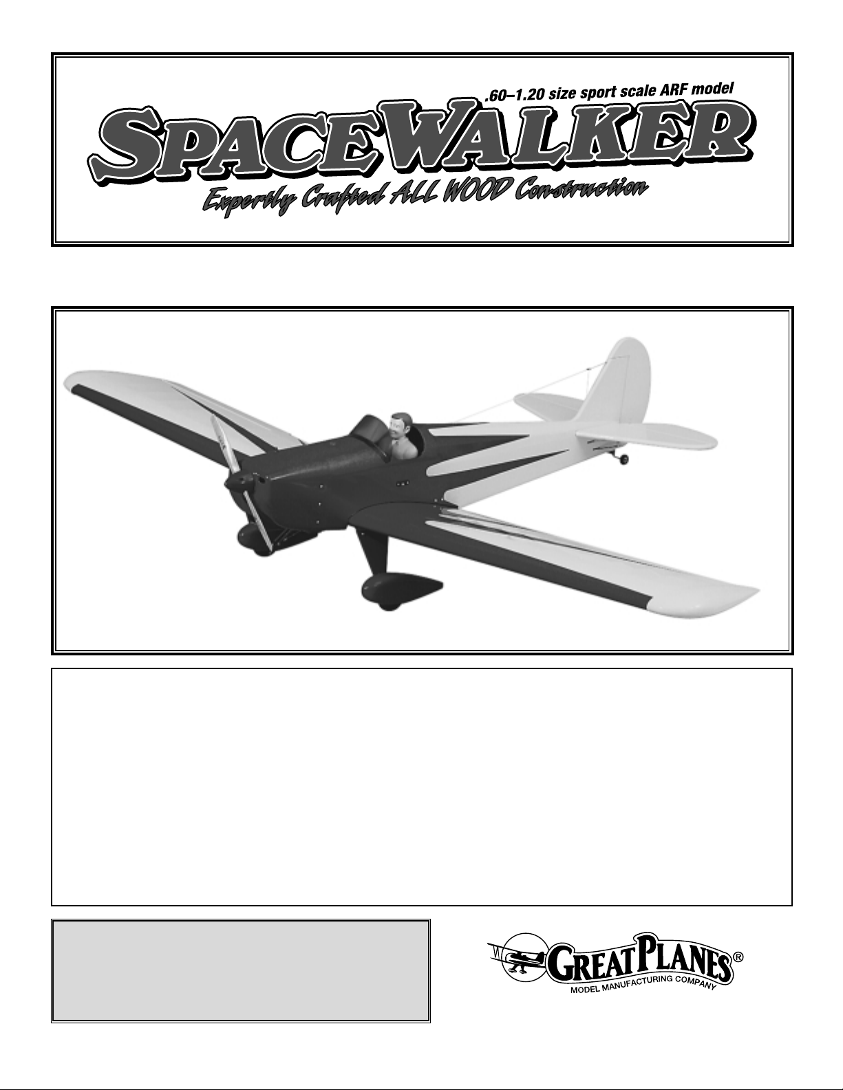
If you have been looking for a way to WOW them at the
field without a lot of work, you have just found it. The Great
Planes SpaceWalker ARF is a balsa, built-up, semi-scale,
1/4 scale airplane that assembles in only a few hours and
is easy on the budget. It does not require any special
building or flying skills. With its thick airfoil and light wing
loading, the SpaceWalker is great for a day of relaxed
flying. What
more can we say? Impress your flying buddies
and
maximize your fun for minimal cost and time!
The Great Planes SpaceWalker ARF combines the design
expertise and high quality standards of all Great Planes kits
with state-of-the-art ARF technology - for craftsmanship and
performance superior to all other pre-built models.
However, this is not a beginner ’s airplane! While the
SpaceWalker ARF is easy to assemble, we must discourage
you from selecting this kit as your first R/C airplane. It is
highly maneuverable, and lacks the self-recovery
characteristics of a good basic trainer such as the Great
Planes PT™Series airplanes. On the other hand, if you are
confident with your flying skills and can safely handle
aileron airplanes, the SpaceWalker ARF is an excellent
choice.
1. You must assemble the model according to the
instructions.
Do not alter or modify the model, as doing so may result in
an unsafe or unflyable model. In a few cases the
instructions may differ slightly from the photos. In those
instances the written instructions should be considered
as correct.
2. Take time to build straight, true and strong.
PRECAUTIONS
INTRODUCTION
PROTECT YOUR MODEL,YOURSELF
& OTHERS...FOLLOW THIS
IMPORTANT SAFETY PRECAUTION
TABLE OF CONTENTS
2
Page 3
3. Use an R/C radio system that is in first-class condition,
and a correctly sized engine throughout the building
process.
4. You must properly install the R/C radio system and other
components so that the model operates correctly on the
ground and in the air.
5. You must test the operation of the model before every
flight to insure that all equipment is operating and you must
make certain that the model has remained structurally
sound. Be sure to check clevises or other connectors often
and replace them if they show signs of wear or fatigue.
Remember: Take your time and follow directions to end
up with a well-built model that is straight and true.
Please inspect all parts carefully before starting to build!
YOU CAN CONT ACT US...
If any parts are missing, broken or defective, or if you
have any questions about building or flying this
airplane, please call us at (217) 398-8970. You can also
check our web site at www.greatplanes.com for the
latest SpaceWalker ARF updates, or e-mail your
questions to productsupport@greatplanes.com. If you
are calling for replacement parts, please reference the
part numbers and have them ready when calling.
Items in parentheses (GPMQ4243) are suggested part
numbers recognized by distributors and hobby shops and
are listed for your ordering convenience. GPM is the Great
Planes brand, TOP is the Top Flite®brand, and HCA is the
Hobbico®brand.
❏ 4-Channel Radio With 4 Standard Servos and 1 servo
with 45 oz.-in. or more of torque
❏ Engine – See Engine Selection
❏ Propeller (Top Flite
®
Power Point™–Refer To Your
Engine’s Instructions For Proper Size)
❏ Medium Fuel Tubing (GPMQ4131)
❏ 1/4 Scale Pilot Figure
❏ 1/4" Foam Rubber (HCAQ1000)
❏ Switch and Charge Jack (GPMM1000)
❏ Large Scale Control Horns (2)
❏ 24" Servo Extension (2)
❏ “Y” Harness
These are the building tools that are required. We
recommend Great Planes Pro™CA and Epoxy glue.
❏ 1/2 oz. Pro CA (Thin, GPMR6001)
❏ 1 oz. Pro CA+ (Medium, GPMR6008)
❏ 6-Minute Pro Epoxy (GPMR6045)
❏ 30-Minute Pro Epoxy (GPMR6047)
❏ Epoxy Brushes (GPMR8060)
❏ Mixing Cups (GPMR8056)
❏ Canopy Glue
❏ Pro Thread Locking Compound (GPMR6060)
❏ T-pins (HCAR5150)
❏ Isopropyl Alcohol (70%)
❏ Hobby Knife (HCAR0105), #11 Blades (HCAR0211)
❏ Dead Center
™
Hole Locator (GPMR8130)
❏ Small Phillips and Flat Blade Screwdrivers
❏ Pliers w/Wire Cutter (HCAR0630)
❏ 4mm Hex Wrench (HCAR0521)
❏ Sealing Iron (COVR2700)
❏ Heat Gun (TOPR2000)
❏ Straightedge w/Scale (HCAR0475)
❏ Builders Triangle Set (HCAR0480)
❏ Masking T ape (TOPR8018)
❏ Sandpaper (coarse, medium, fine grit)
❏ Easy-Touch
™
Bar Sander (GPMR6170, or similar)
❏ Paper T owels
❏ Electric Drill
❏ Drill Bits: 1/16", 7/64", 1/8", 3/32", 3/16", 7/32" 5/32"
1/4", 5/64" (HCAR0699)
❏ Petroleum Jelly
❏ CAApplicator Tips (HCAR3780)
❏ CA Debonder (GPMR6039)
❏ Curved Tip Canopy Scissors For Trimming
Plastic Parts (HCAR0667)
❏ Fuel Filler Valve (GPMQ4160)
❏ Bar Of Hand Soap
Optional Supplies and Tools
Building Supplies and Tools
Required Accessories
PREPARATIONS
Engine Selection
There are several engines that will work well in your
SpaceWalker ARF. We recommend a hot 2-stroke such
as an O.S.®.61FX or SuperTigre™G61. For
unsurpassed
power and realistic sound, an O.S. FS-70 or FS-90
4-stroke can’t be beat.
DECISIONS YOU MUST MAKE
Note: We, as the kit manufacturer, provide you with a
top quality kit and great instructions, but ultimately the
quality of your finished model depends on how you build
it; therefore, we cannot in any way guarantee
the performance of your completed model, and no
representations are expressed or implied as to the
performance or safety of your completed model.
3
Page 4

4
Remove the fuselage, wing panels, rudder assembly and stabilizer assembly from their bags. Inspect all items closely to
check for any damage. If any damage is found, contact the place where your SpaceWalker ARF was purchased, or Hobby
Services, to obtain a replacement for your damaged items.
The Great Planes SpaceWalker ARF is an excellent sport scale model. Because the SpaceWalker ARF is 1/4 scale it is
eligible for IMAA events. The IMAA (International Miniature Aircraft Association) is an organization that promotes
non-competitive flying of giant scale models.
IMAA
205 S. Hilldale Road
Salina, KS 67401
Tele. (913) 823-5569
If you intend to fly the SpaceWalker ARF at IMAA events, it may be necessary to replace the 2-56 pushrods, clevises and
control horns with 4-40 pushrods, clevises and control horns designed for 1/4 scale airplanes. Although the plane flies
great with the hardware supplied, many events require the use of 4-40 style hardware. Also, all control surface related
servos must have at least 45 in.-oz. of torque in IMAA events.
IMAA Information
General Inspection
1/64" = .4 mm
1/32" = .8 mm
1/16" = 1.6 mm
3/32" = 2.4 mm
1/8" = 3.2 mm
5/32" = 4.0 mm
3/16" = 4.8 mm
1/4" = 6.4 mm
3/8" = 9.5 mm
1/2" = 12.7 mm
5/8" = 15.9 mm
3/4" = 19.0 mm
1" = 25.4 mm
2" = 50.8 mm
3" = 76.2 mm
6" = 152.4 mm
12" = 304.8 mm
18" = 457.2 mm
21" = 533.4 mm
24" = 609.6 mm
30" = 762.0 mm
36" = 914.4 mm
Metric Conversions
Inch Scale
0" 1" 2" 3" 4" 5" 6" 7"
0 10 20 30 40 50 60 70 80 90 100 110 120 130 140 150 160 170 180
Metric Scale
Page 5
5
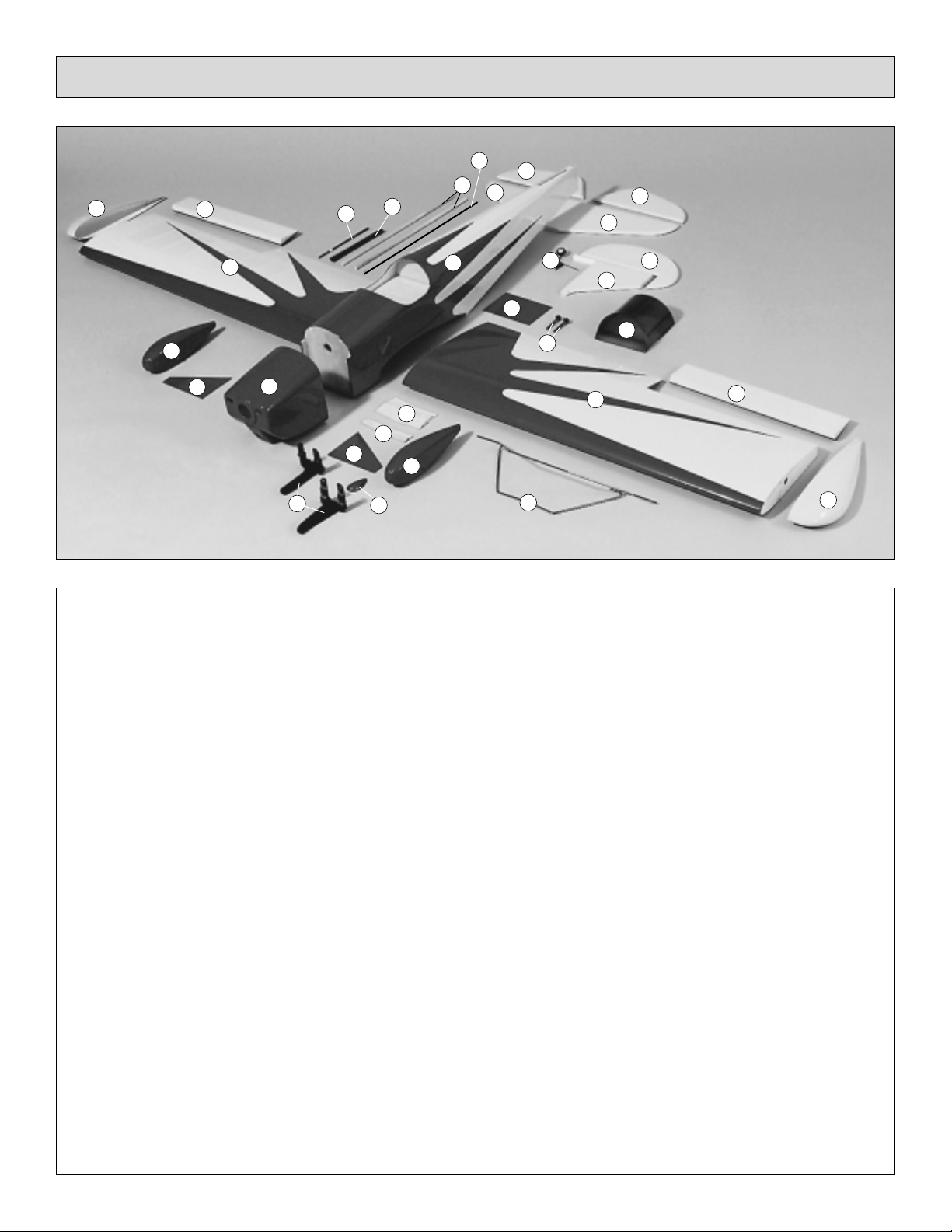
Key# Description Qty
1 Fuselage 1
2 Wing Panel Right & Left 2
3 Wing Tips 2
4 Aileron Right & Left 2
5 Forward Plywood Wing Joiner 3
6 Aft Plywood Wing Joiner 2
7 Wing Bolt Plate 1
8 Horizontal Stabilizer 1
9 Vertical Fin 1
10 Rudder 1
11 Elevator 2
12 Wire Landing Gear 1
13 Main Landing Gear Cover 2
14 Wheel Pants 2
15 Cowl 1
16 Windshield 1
17 Scale Fuel Level Fairing 1
18 Adjustable Engine Mount Right & Left 2
19 1" Tail Wheel 1
20 Wood Dowel Pushrod 2
21 Plastic Heat Shrink Tubing 1
22 Throttle Pushrod 1
23 2-56 x 12" Threaded Pushrod 7
24 5mm x 50.8mm Wing Bolt 2
Parts Included in the Hardware Bag
Inner Throttle Pushrod 1
2-1/2" Main Wheels 2
2-1/2" Spinner 1
Cockpit Coaming 1
Large Nylon Control Horn 3
Nylon Clevis 5
Silicone Clevis Retainer 5
Faslink Pushrod Keeper 4
CA Hinge Strip 1
14 oz. Fuel Tank 1
Screw-Lock™Pushrod Connector 1
Pushrod Connector Retainer 1
Description Qty
4-40 Hex Nut 6
4-40 Lock Nut 4
8-32 Blind Nut 4
2-56 x 1/8" Set Screw 1
2-56 x 5/8" Machine Screw 6
4-40 x 1/8" Socket Head Cap Screw 1
4-40 x 3/8" Machine Screw 6
4-40 x 3/4" Machine Screw 4
6-32 x 1/8" Set Screw 4
8-32 x 1" Socket Head Cap Screw 4
#2 x 3/8" Sheet Metal Screw 4
#4 x 1/2" Sheet Metal Screw 18
#6 x 1" Sheet Metal Screw 4
3/32" Wheel Collar 1
3/16" Wheel Collar 4
#4 Flat Washer 20
#8 Flat Washer 4
#8 Lock Washer 4
Landing Gear Cover Brackets 6
Wheel Pant Bracket 2
3mm x 9.5mm Machine Screw 2
Landing Gear Straps 4
Replacement Parts
If needed, replacement parts for SpaceWalker ARF are available through
your hobby supplier.
Canopy .....................................................................................GPMA2163
Cowl..........................................................................................GPMA2164
Spinner.....................................................................................GPMQ4522
Wing Set ...................................................................................GPMA2160
Tail Fin Set ................................................................................GPMA2162
Fuselage Set.............................................................................GPMA2161
Landing Gear Set......................................................................GPMA2165
Parts List
616933
5
141415
111110
1222
19
1
20
22
788
4
41313
23
181724
21
Page 6
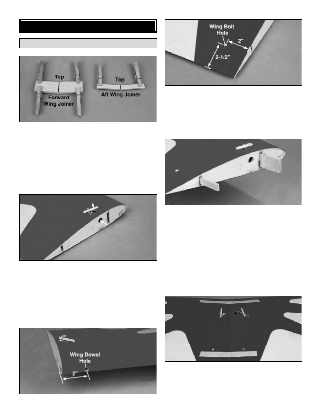
❏ 1. Use 5-minute epoxy to glue the three plywood forward
wing joiners together and the two aft wing joiners
together. Use clothespins or c-clamps to clamp the joiners
together until the epoxy cures. Wipe off any excess epoxy
with a paper towel and isopropyl alcohol before it cures.
Draw a vertical centerline on the forward and aft wing
joiners.
❏
2. Use a sharp hobby knife to cut the covering from the
servo cord exits on the top of each wing half. Carefully
untie the string from the stick at the root rib and route the
string through the servo cord exit. Re-tie the strings around
the stick.
❏
3. Use a sharp hobby knife to cut the covering from the
wing dowel holes in the leading edge and the wing bolt
holes at the trailing edge of each wing half. The wing dowel
holes are approximately 2" [50.8mm] from the wing root.
The wing bolt holes are approximately 2" [50.8mm] from
the wing root and 2-1/2" [63.5mm] from the trailing edge.
❏4.
Test fit the wing joiners in both wing halves. A snug fit
is desirable. If the joiners do not fit properly, lightly sand the
edges and sides of the joiners. Note: The plywood wing
joiners have a slight dihedral angle. This angle should point
toward the top of the wing.
When satisfied with the fit of the
wing joiners, use 30-
minute epoxy to glue the joiners in the
left wing half. Use plenty of epoxy, making sure the joiners
are glued to the spars and shear webs. Before the epoxy
cures, make sure the joiners are straight and in good
contact with the spars. Wipe off any excess epoxy from the
root rib and the wing covering using a paper towel
dampened with isopropyl alcohol.
❏
5. Test fit the two wing halves together. The wing halves
should seat together without any gaps and the front and
back edges of each wing should line up with each other.
Completely cover the exposed portion of the wing joiners,
spars and root ribs with 30-minute epoxy. Slide the two
Join the Two Wing Halves
WING ASSEMBL Y
6
Page 7
wing halves together, removing any excess epoxy with a
paper towel dampened with isopropyl alcohol. Use masking
tape to hold the wing halves together while the epoxy cures.
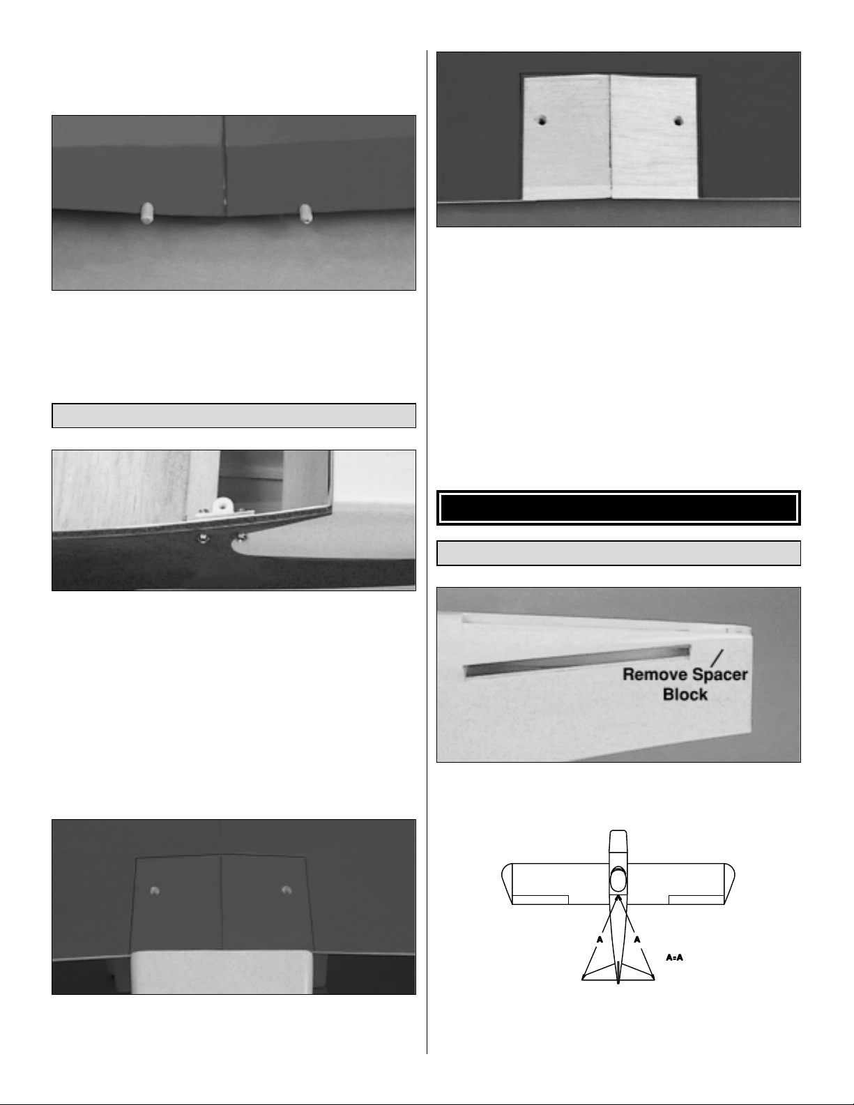
❏
6. Use 6-minute epoxy to glue the two 1-5/8" [41.3mm]
wing dowels in the wing dowel holes. The rounded end
should protrude from the wing approximately 1/2"
[12.7mm].
❏
1. The plastic wing bolt mounts are temporarily glued to
the inside of the fuselage. Use a T-pin to locate the four
wing bolt mounts’ screw holes in the side of the fuselage.
Use a sharp hobby knife to cut the covering from the screw
holes. Use four 4-40 x 3/4" machine screws, four #4 flat
washers and four 4-40 lock nuts to attach the wing bolt
mounts to the fuselage sides. Do not crush the balsa
fuselage sides by overtightening the screws.
❏
2. Test fit the wing on the fuselage, checking that the
wing bolts will thread into the wing bolt mounts. Remove
the wing bolts from the wing.
❏
3. With the wing centered on the fuselage, center the
plywood wing bolt plate on the aft edge of the wing. Trace
the outline of the wing bolt plate onto the wing.
❏
4. Use a sharp hobby knife to trim the covering from the
wing, 1/8" [3.2mm] inside the wing bolt plate outline. Be
careful to not cut into the balsa wood of the wing as this
will weaken it.
❏
5. Glue the wing bolt plate to the wing using 6-minute
epoxy. Wipe off any excess epoxy with a paper towel
dampened with isopropyl alcohol. Hold the wing bolt plate
in place with clamps until the epoxy cures.
❏
6. Drill two 1/4" [6.3mm] holes through the wing bolt
plate using the pre-drilled holes in the wing as a guide. Test
fit the wing on the fuselage, making sure the wing bolts
align with the wing bolt mounts.
❏
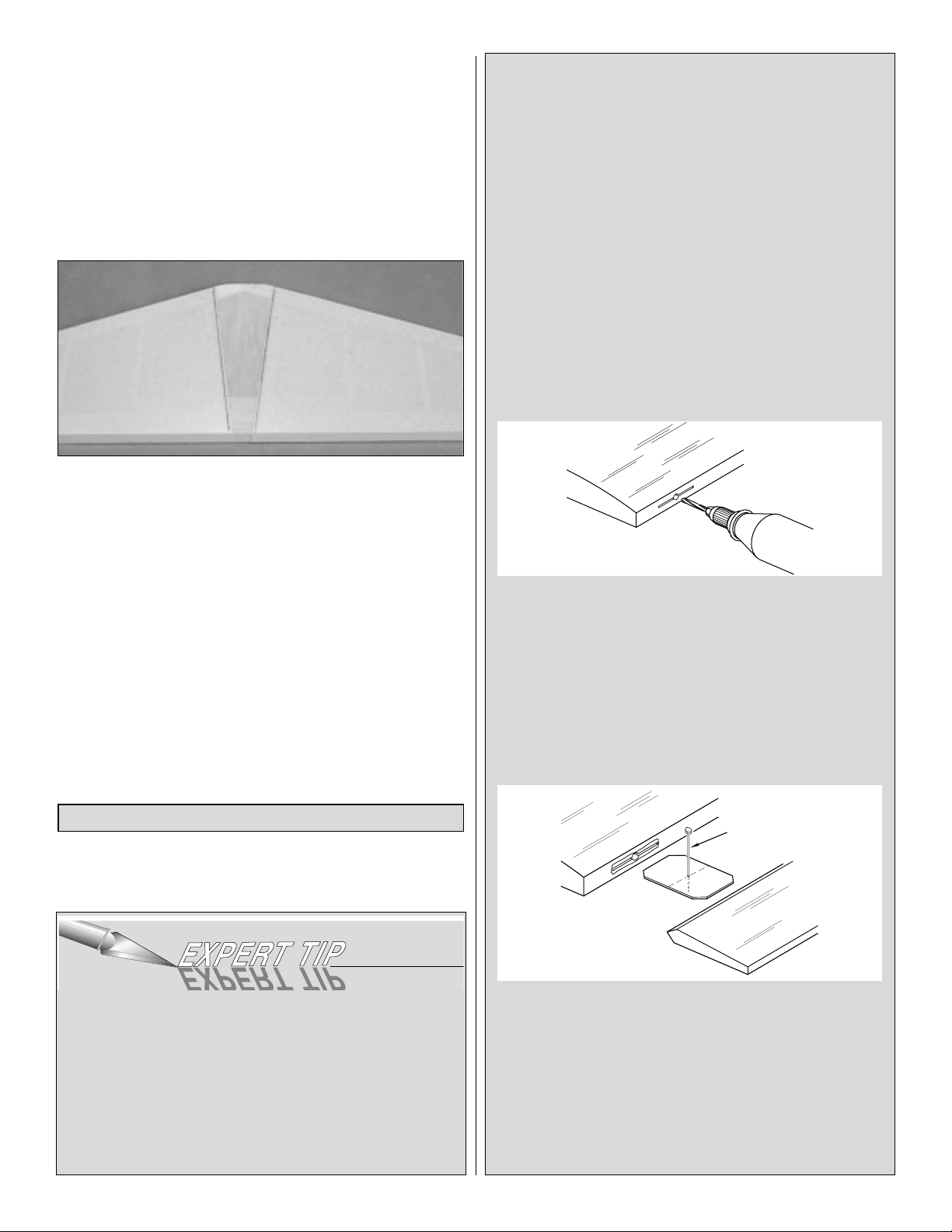
1. Trim the covering from the stabilizer slot. Remove the
balsa spacer block at the aft end of the slot.
❏
2. Draw a centerline on both sides of the stabilizer.
Center the stabilizer in the stabilizer slot. Attach a piece of
string with a T-pin to the fuselage centerline as shown.
Install the Stabilizer and Vertical Fin
TAIL ASSEMBLY
Mount the Wing to the Fuselage
7
Page 8
Stretch the string to one corner of the stabilizer. Repeat the
procedure on the other side of the stabilizer. Adjust the
angle of the stabilizer until the distance from the pin to the
stabilizer is equal on both sides. With the wing installed,
sight the aft end of the plane from 8' to 10' back. If the
stabilizer is not parallel to the wing, carefully sand the high
side of the stabilizer slot.
❏
3. Carefully use a felt-tip pen to mark where the fuselage
sides contact the top and bottom of the stabilizer.
❏
4. Remove the stabilizer from the fuselage. Carefully
trim the covering from inside the marks. Important: You
must not cut into the wood, as this will weaken the stabilizer
which may cause it to break in flight.
❏
5. Apply 30-minute epoxy to the bare wood at the center
of the stabilizer. Insert the stabilizer back into the stabilizer
slot. Use the pin and string method to confirm the stabilizer
alignment. Wipe off any excess epoxy before it cures, then
recheck alignment.
❏
6. Test fit the vertical fin in the fin slot. Use a Hobbico
Builder’s Triangle to ensure that the fin is perpendicular to
the stabilizer. Use 30-minute epoxy to glue the fin to the
stabilizer and fuselage. Hold the fin in position with masking
tape until the epoxy cures.
❏
1. You may need to cut the covering from the hinge slots
in the elevator and stabilizer.
INSTALLING CA HINGES
The hinge material supplied in this kit consists of a
3-layer lamination of mylar and polyester. It is specially
made for the purpose of hinging model airplane control
surfaces. Properly installed, this type of hinge provides
the best combination of strength, durability and ease of
installation. We trust even our best show models to
these hinges, but it is essential to install them correctly.
Please read the following instructions and follow them
carefully to obtain the best results. These instructions
may be used to effectively install any of the various
brands of CA hinges.
The most common mistake made by modelers when
installing this type of hinge is not applying a sufficient
amount of glue to fully secure the hinge over its entire
surface area; or, the hinge slots are very tight, restricting
the flow of CA to the back of the hinges. This results in
hinges that are only “tack glued” approximately 1/8"
[3.2mm] to 1/4" [6.3mm] into the hinge slots. The
following technique has been developed to help ensure
thorough and secure gluing.
Drill a 3/32" [2.4mm] hole, 1/2" [12.7mm] deep, in the
center of the hinge slot. If you use a Dremel Moto-Tool
™
for this task, it will result in a cleaner hole than if you use
a slower speed drill. Drilling the hole will twist some of
the wood fibers into the slot, making it difficult to insert
the hinge, so you should insert a knife blade, working it
back and forth a few times to clean out the slot.
It is best to leave a very slight hinge gap, rather than
closing it up tight, to help prevent the CA from wicking
along the hinge line. Make sure the control surfaces will
deflect to the recommended throws without binding. If
your hinge slots are cut too deep, the hinges may slide
in too far, leaving only a small portion of the hinge in the
control surface. To avoid this, you may insert a small pin
through the center of each hinge before installing. This
pin will keep the hinge centered while you install the
control surfaces.
Install the Rudder, Elevators and Ailerons
8
DRILL A 3/32" HOLE
1/2" DEEP, IN CENTER
OF HINGE SLOT
TEMPORARY PIN
TO KEEP HINGE
CENTERED
Page 9

❏
2. Apply 6 drops of thin CA adhesive to both sides of
each hinge in the elevator. Allow a few seconds between
drops for the CAto wick into the slot.
❏
3. Install the ailerons, centering them in the aileron bay.
Repeat the hinge gluing technique described previously.
Note: On the red side of the aileron, in the second rib bay
from the inward end, there is a horn block along the leading
edge. This block must line up with the aileron servo hole in
the wing.
❏
4. Make a 90° bend in the tailgear wire 1" from the end
of the wire. Install the 1" tail wheel and secure it to the
tailgear
wire with a 3/32" wheel collar and 2-56 x 1/8"
set screw.
❏
5. Position the tailgear on the bottom of the aft end of
the fuselage. Center the tailgear mount with the tailgear
wire against the fuselage. Mark the four mounting holes in
the tailgear mount.
❏
6. At each mark drill a 1/16" [1.6mm] pilot hole. Attach
the tailgear to the bottom of the fuselage with four #2 x 3/8"
sheet metal screws.
❏
7. Hold the rudder in position on the trailing edge of the
vertical fin. There should be a 1/16" [1.6mm] gap between
the top of the vertical fin and the rudder balance tab. Mark
the tailgear arm location where it will enter the leading edge
of the rudder.
❏
8. Drill a 3/32" [2.4mm] hole, 1-1/4" [31.7mm] deep, in
the leading edge of the rudder at the tailgear arm location.
Cut a groove for the tailgear wire in the leading edge of the
rudder from the 3/32" [2.4mm] hole to the bottom of the
rudder.
❏
9. Apply a little petroleum jelly to the tailgear wire where
it passes through the nylon bearing. This will prevent the
wire from being glued into the bearing.
❏
10. Prepare the hinge slots in the rudder the same way
you did for the elevators.
❏11. Roughen the tailgear wire arm with coarse
sandpaper
and clean with alcohol to improve glue adhesion. Use a
toothpick to pack the tailgear arm hole in the rudder with
30-minute epoxy. Join the rudder to the fin with the hinges.
Wipe off the excess epoxy with a paper towel dampened
with isopropyl alcohol. Repeat the hinge gluing technique
described previously after allowing the epoxy to cure.
❏
12. Roughen the inside of the plastic wing tips and
approximately 1/8" of the covering at the end of the wing
with 400-grit sandpaper before gluing. Use 30-minute
epoxy to glue the two wing tips onto the end of the wing.
Note that the lip on the wing tip fits over the wing. Use a
9
Page 10

paper towel dampened in isopropyl alcohol to wipe off any
excess epoxy before it cures.
❏1. Trim the covering from the three mounting holes in
each
main landing gear cover.
❏
2. Attach each landing gear cover to the main landing
gear with three metal landing gear cover brackets, 4-40 x
3/8" machine screws, #4 washers and 4-40 nuts. Be
sure to use thread lock on the machine screws to prevent
the nuts from vibrating loose.
❏
3. Note that there is a bump (axle guide) on each side of
the wheel pant. Trim one of the molded axle guides from
each wheel pant. Important: Be sure to make a left and
right wheel pant.
❏❏
4. Position the wheel pant bracket on the wheel
pant, centered over the axle guide hole. Mark the two
bracket mounting holes on the wheel pant. A T-pin works
great for this. Important: The 3mm screw hole in the side
of the bracket must be towards the bottom.
❏❏
5. Drill a 1/8" hole at both marks on the wheel pant.
Attach the wheel pant bracket to the inside of the wheel
pant with two #4 x 1/2" sheet metal screws and #4
washers.
❏❏
6. Drill a 3/16" [4.7mm] hole in the bottom of the pant,
aligned with the 3mm hole in the side of the wheel pant
bracket. See the drawing in step 7.
❏❏
7. File a flat spot along the bottom of the landing gear
axle. Slide one wheel pant onto the landing gear axle
followed by one of the 3/16" wheel collars, a 2-1/2" wheel
and a second wheel collar. The landing gear axle should
seat in the outside axle guide. Screw a 6-32 x 1/8" set
screw into each of the wheel collars. Be sure to use thread
lock on the set screws to prevent them from vibrating loose.
❏❏
8. Secure the wheel pant to the landing gear with a
3mm x 3/8" machine screw threaded into the wheel pant
bracket. Again, be sure to apply thread lock to the machine
screw before tightening.
Return to step 4 and install the second wheel pant.
INSTALL THE MAIN LANDING GEAR
10
WHEEL PANT
MAIN LANDING GEAR
#4 X 1/2" SHEET
METAL SCREW
WHEEL PANT BRACKET
3MM X 3/8" MACHINE SCREW
DRILL HOLE IN BOTTOM
OF THE WHEEL P ANT
3/16" WHEEL COLLAR
3/16" WHEEL COLLAR
AXLE
GUIDE
Page 11

❏
9. Trim the covering from the main landing gear slots on
the bottom of the wing. Apply a small amount of thin CA
along the slot to insure it is fuelproofed.
❏
10. Insert the main landing gear in the landing gear
slots. Position the four nylon landing gear straps over the
landing gear and mark the mounting hole locations.
❏
11. Drill a 3/32" [2.4mm] pilot hole at each mark.
❏12. Attach the landing gear straps to the wing with #4 x
1/2"
sheet metal screws.
❏1. Position the engine mount template (found on page
21
of this instruction manual) on the firewall. Align the
centerlines
of the template with the embossed marks on the firewall.
The marks on the firewall are off center to allow for the
built-in right thrust of the firewall.
❏
2. Mark the engine mount bolt holes and drill a 7/32"
[5.5mm] hole through the firewall at each mark.
❏
3. Insert an 8-32 blind nut into each hole from the
backside of the firewall. Use an 8-32 x 1" socket head cap
screw and #8 flat washer to seat the blind nuts in the back
of the firewall.
❏
4. Cut the “spreader bar” from the supplied Great Planes
adjustable engine mount. Use a hobby knife to remove
any flashing left over from the molding process so that the
halves fit together without any binding.
❏5. Temporarily install the engine mount on the firewall with
four 8-32 x 1" socket head cap screws, #8 lock washers
and #8 flat washers. Do not tighten the screws all the way
so you can adjust the mount.
❏
6. Place your engine on the mount and adjust the halves
to fit the engine. Position the mount so the molded-in “tick
marks” are equally spaced on the horizontal off set line on
the firewall. When the engine mount is adjusted and
positioned, tighten the mounting screws.
❏
7. Position the engine on the mount so the drive washer
(or the back of the spinner) is 6-1/4" [158.7mm] away from
the firewall. Use a Great Planes Dead Center™Hole
Locator to mark the engine mounting holes.
❏
8. Drill a 7/64" [2.8mm] hole at each mark. Mount the
engine to the engine mount with four #6 x 1" sheet metal
screws. Hint: The screws will be easier to install if you first
rub the threads on a bar of soap.
Note: On some engines the carburetor can be rotated so
that the needle valve points towards the top of the plane.
ENGINE INSTALLATION
11
Page 12

❏
9. Drill a 5/32" [3.9mm] hole through the firewall and the
second former, in line with the throttle arm on the engine.
❏
10. Use coarse sandpaper to roughen the outside of the
throttle outer pushrod tube so the glue adheres well.
Insert
the outer tube through the firewall and second former. Glue
the outer tube in place, leaving approximately 1/2"
[12.7mm] of the tube protruding from the front of the firewall.
❏
1. Install the servos in the servo tray, spacing them apart
as necessary so the servo arms do not interfere with each
other. Note: We recommend that a servo with at least 45
oz-in. [3.25 kg-cm] of torque be used on the elevators.
❏ 2. Install the receiver switch on the left side of the
fuselage. We prefer a Great Planes Switch & Charge Jack
Mounting Set (GPMM1000). This allows the receiver battery
to be checked and charged at the flying field without
removing the wing. Wrap the receiver and receiver battery
in 1/4" [6.4mm] foam rubber to protect them from vibration.
Plug the servos, receiver switch and Y-harness into the
receiver. Secure the receiver in the fuselage with a couple
of scrap sticks glued to the sides of the fuselage.
Note: Do not permanently mount the receiver battery until
the step “Balance Your Model” on page 18 has been
completed.
❏
3. On our models we drilled a 1/16" [1.2mm] hole
through the top stringer of the turtledeck just behind the
cockpit. The receiver antenna is routed along the inside of
the fuselage and out this hole. The antenna is attached to
the fin with a T-pin, rubber band and a cut off servo arm.
❏
4. Temporarily install the brass Screw-Lock™Pushrod
Connector in the throttle servo arm. Slide a silicone
clevis retainer over the threaded end of a 2-56 x 36"
pushrod. Thread a nylon clevis 14 turns onto the
pushrod. Attach the clevis to the throttle arm on the
carburetor. Slide the throttle pushrod through the outer
pushrod tube and pushrod connector. Install a 4-40 x 1/8"
socket head cap screw in the pushrod connector.
Connect the clevis to the throttle arm and slide the silicone
clevis retainer into place.
Install the Throttle, Elevator and
Rudder Servos
RADIO INSTALLATION
12
Page 13

❏
5. If you installed a 2-stroke engine on your plane, install
the muffler and bend the throttle pushrod as needed to
avoid interference between the muffler.
❏
6. Switch your radio system on. Check that the throttle
opens and closes completely using the throttle stick and
trim on the transmitter. (See your radio instruction manual
for proper adjustment.) When satisfied with the operation of
the throttle, permanently attach the pushrod connector to
the servo arm with the plastic retainer and tighten the cap
screw onto the pushrod. Cut off the excess pushrod.
❏
7. Glue the throttle outer pushrod tube to the formers to
secure it in position.
❏
8. Cut both wood dowels to 14" [355.6mm] long.
❏
9. In one of the wood dowels, drill 5/64" [2mm] holes
through the dowel, 2" [50.8mm] from each end. On each
end of the dowel, use a hobby knife to cut a groove from
the hole to the end of the dowel, deep enough for a 2-56
threaded pushrod to fit in.
❏
10. From the threaded end of a 2-56 x36" pushrod, cut
an 11" [279.4mm] long piece. Cut a second non-threaded
11" [279.4mm] piece from the same 36" pushrod. Make a
90° bend 1/4" [6.4mm] from the non-threaded end of both
11" pushrods. Insert the “bent end” of the wire into the
holes in the wood dowel.
❏11. Cut the 8" [203mm] shrink tubing into four 2"
[50.8mm]
pieces. Slide a 2" [50.8mm] piece over each end of the
wood dowel and pushrod. Use a heat gun to shrink the
tubing tight around the dowel. Apply several drops of thin
CA to each end of the shrink tubing to secure it to the
dowel. This is now the rudder pushrod.
❏
12. Trim the covering from the two elevator pushrod
exits and the rudder pushrod exit at the aft end of the
fuselage. Apply a small amount of thin CA around the exits
to fuelproof them.
❏
13. Insert the rudder pushrod into the fuselage with the
threaded rod exiting out the rudder exit slot. Slide a silicone
clevis retainer over the rudder pushrod and screw a nylon
clevis 14 turns onto the rudder pushrod.
❏
14. Attach a control horn to the clevis. Align the clevis
holes in the control horn with the hinge line of the rudder.
Mark the control horn mounting holes.
❏
15. Drill a 3/32" [2.4mm] hole at both marks. Mount the
rudder control horn to the rudder with the backing plate and
two 2-56 x 5/8" machine screws. Slide the silicone retainer
over the clevis to secure it in place.
❏
16. With the servos centered and the rudder in the
neutral position, use a felt-tip pen to mark where the
pushrods cross the mounting holes in the servo arms.
❏
17. Make a 90° bend at the mark you made. Insert the
rudder pushrod in the rudder servo horn and secure it with
13
FasLink
Servo Horn
2-56 (.074") Pushrod Wire
Page 14

a nylon Faslink. Cut the excess pushrod so it slightly
protrudes out of the Faslink.
Note: If necessary, enlarge the hole in the servo arm with a
5/64" [2mm] drill bit (or a #48 bit for precision).
❏
18. In the second wooden dowel, drill 5/64" [2mm] holes
through the dowel, 2" [50.8mm] from each end. On one of
the ends, also drill a hole 1-1/2" [38mm] from the end. On
each end of the dowel, use a hobby knife to cut a groove
from the holes to the end of the dowel, deep enough for a
2-56 threaded pushrod to fit in. The groove for the 1-1/2"
[38mm] hole should be on the opposite side from the
groove for the 2" [50.8mm] hole.
❏
19. Cut 1-1/2" [38mm] off of the non-threaded end of a
2-56 x 12" threaded pushrod. From the threaded end of a
2-56 x 36" pushrod, cut an 11" [279.4mm] long piece. Cut a
second non-threaded 11" [279.4mm] piece from the same
36" pushrod. Make a 90° bend 1/4" [6.4mm] from the nonthreaded end of the 10-1/2" and both 11" pushrods. Insert
the two 11" [279.4mm] pushrods in the holes, 2" [50.8mm]
from the end of the wooden dowel. The 10-1/2" [266.7mm]
pushrod is inserted in the hole 1-1/2" [38mm] from the end.
❏
20. Slide a 2" [50.8mm] piece of shrink tubing over each
end of the wood dowel and pushrods. Use a heat gun to
shrink the tubing tight around the dowel and use thin CA to
secure it to the dowel. This is now the elevator pushrod.
❏
21. Following the same procedure used to install the
rudder pushrod, insert the elevator pushrod into the
fuselage with the two threaded rods exiting out the elevator
exit slots. Hint: Bend the pushrods apart slightly. It’s best to
guide one pushrod out one of the pushrod exits. Align the
second rod with the other pushrod exit and use a hobby
knife or small flat screwdriver to guide it out the exit. Slide
silicone clevis retainers over the threaded rods and screw
nylon clevises 14 turns onto the threaded rods.
❏
22. Attach a control horn to both clevises. Align the
adjustment holes in the control horns with the hinge line of
the elevator. Mark the control horn’s mounting holes.
❏
23. Drill a 3/32" [2.4mm] hole at each mark. Mount the
elevator control horns to the elevators with the backing
plate and 2-56 x 5/8" machine screws. Slide the silicone
retainer over the clevis to secure it in place.
❏
24. With the elevator servo centered and the elevators in
the neutral position, use a felt-tip pen to mark where the
pushrod crosses the mounting holes in the servo arm.
❏
25. Make a 90° bend at the mark you made. Insert the
elevator pushrod in the elevator servo horn and secure it
with a nylon Faslink. Cut the excess pushrod so it slightly
protrudes out of the Faslink. Note: If necessary, enlarge the
hole in the servo arm with a 5/64" [2mm] drill bit (or a #48
drill for precision).
❏❏
1. Trim the covering from the aileron servo tray on the
bottom of the right wing half.
❏❏
2. Plug a 24" [609.6mm] servo extension into the
aileron servo. As a precaution, use tape or shrink tubing
(not included) to prevent the connectors from separating.
❏❏
3. Carefully pull the string in the aileron servo bay out
enough to tie it to the end of the 24" servo extension.
Gently pull the extension through the wing until it exits at
the center of the wing.
Install the Aileron Servos
14
Page 15

❏❏
4. Mark the aileron servo mounting hole locations on
the wing. Remove the aileron servo and drill a 1/16"
[1.6mm] hole at each mark. Mount the aileron servo in the
wing with the mounting screws included with the servo.
❏❏
5. Trim three of the four arms from a cross servo arm.
Plug the aileron servo into your receiver, switch the radio
system on and center the aileron servo. Install the servo
arm on the servo so that it is perpendicular to the centerline
of the servo. Screw a nylon clevis 14 turns onto a 2-56 x
12" threaded pushrod. Attach the clevis to a control horn
and position the control horn on the aileron so that the
pushrod is aligned with the servo arm, and the adjustment
holes in the horn are aligned with the aileron hinge line.
Mark the horn mounting holes.
❏❏
6. Mount a large scale control horn (not included), to
the aileron following the manufacturer’s instructions.
❏❏7. With the ailerons in the neutral position, use a felt-
tip
pen to mark where the pushrod crosses the mounting holes
in the servo arm.
❏❏
8. Slide a silicone retainer on the pushrod and over
the clevis. Make a 90° bend in the pushrod at the mark you
made in step 7. Insert the aileron pushrod in the aileron
servo horn and secure it with a nylon Faslink. Cut the
excess pushrod so it slightly protrudes out of the Faslink.
Note: If necessary, enlarge the hole in the servo arm with a
5/64" [2mm] drill bit (or a #48 drill for precision).
❏
9. Return to step 1 of “Install The Aileron Servos” and
install the second aileron servo. Note: Install the servo
arms so that they both point outward, toward the wing tips.
❏
10. Plug both ailerons into the “Y” cable.
❏
1. Use strips of thin cardboard or plastic to make
templates to locate the head of the engine and needle
valve. Tape the templates to the fuselage, accurately
indicating the position of the engine head and needle valve.
❏
2. Place the backplate of your spinner on the engine and
check that the distance between the firewall and the
backplate is 6-1/4" [158.7mm]. Remove the engine from the
engine mount, leaving the templates in place. Position the
cowl on the fuselage so the forward edge is 3/32" [2.4mm]
aft of the measurement you just made, or 6-5/32"
[156.3mm] in front of the firewall. Align the cowl on the
fuselage and lightly mark the location of the rear of the cowl
on the fuselage top.
INSTALL THE COWL
15
Page 16

❏
3. Use a felt-tip pen to transfer the template outlines
onto the cowl. Because the cowl comes pre-painted and
removing the marks may be difficult, we recommend you
draw the outline of the template approximately 1/8"
[3.2mm] inside of the template.
❏
4. For convenience, we installed on the left side of the
firewall, a Great Planes Easy Fueler™Fuel Filling Valve
(GPMQ4160) mounted on a piece of 1/8" [3mm] plywood.
To locate the fill valve on the cowl, make a template as
previously done for the engine head. Connect the fuel
tubing from the fuel pick-up to the carburetor (or fill valve)
and the tubing from the pressure fitting to the muffler
pressure tap.
❏
5. Remove the cowl and templates. Re-install the engine
(this should be the last time you need to install it). Install
the muffler on the engine so that the muffler exhaust is
pointing towards the bottom of the firewall.
❏
6. Assemble the fuel tank per the manufacturer’s
instructions. Connect approximately 12" [304.8mm] of fuel
tubing to the fuel pick-up fitting and the pressure fitting on
the tank. Wrap the tank in 1/4" [6.4mm] foam rubber and
slide the tank through the opening in the second former.
The top of the tank must face the top of the fuselage. Route
the fuel tubing through the firewall. Use a stick (not
included) to secure the fuel tank in the fuselage. Optional:
A third piece of fuel tubing may be installed on the fuel tank
for an overflow line and routed to the bottom of the firewall.
Note: This line must be plugged in flight if you intend to
pressurize your fuel tank.
❏
7. Using the template lines drawn on the cowl, cut the
holes for the engine head and needle valve. Also cut out a
cooling hole on the bottom of the cowl as shown. Hint: Cut
the holes in the cowl slightly undersize at first. Test fit the
cowl on the fuselage, making slight adjustments to the
holes as needed.
❏
8. When satisfied with the fit of the cowl, install the
spinner backplate, propeller and spinner cone on the engine.
❏
9. Tape the cowl in position with the cowl front aligned
with the spinner backplate. On both sides of the cowl make
three marks for the cowl mounting screws 1/2" [12.7mm]
from the aft edge. At each mark drill a 3/32" [2.4mm] pilot
hole through the cowl and fuselage sides.
❏
10. Remove the cowl and enlarge the holes in the cowl
to 1/8" [3.2mm]. Mount the cowl to the fuselage with six
#4 x 1/2" sheet metal screws and #4 washers.
❏
1. We recommend that the cockpit area be painted with
a fuelproof paint. We used flat black LustreKote™on
our models.
ADDING DETAILS TO YOUR
SP ACEWALKER ARF
16
Page 17

❏
2. Cut out the windshield along the cut lines and glue it
to the fuselage. Use rubber bands or masking tape to hold
it in position until the glue dries. We recommend a glue
specifically formulated for gluing canopies such as Pacer
“Formula 560” canopy glue. Formula 560 is like regular
white glue (aliphatic resin) in that it dries clear and cleans
up with water, but sticks well to butyrate and completely
dries overnight.
❏
3. Glue the scale fuel level fairing on top of the
fuselage, centered between the windshield and cowl.
❏
4. Apply a small bead of canopy glue along the edge of
the cockpit. Fit the black cockpit coaming all around the
edge of the cockpit and wipe off any excess glue before
it dries.
❏
5. We used a Williams Brothers 1/4 scale old time pilot
#62500 raised up with a 1/2" [12.7mm] block of wood. Paint
the pilot, and after the paint has dried use 6-minute epoxy
and two #4 x 1/2" sheet metal screws (not included) to
mount the pilot to the cockpit floor.
The throws are measured at the widest part of the
elevators, rudder and ailerons. Adjust the position of the
pushrods at the servo horns to control the amount of throw.
You may also use the ATV’s if your transmitter has them,
but the mechanical linkages should still be set so the ATV’s
are near 100% for the best servo resolution (smoothest,
most proportional movement).
We recommend the following control surface throws:
High Rate Low Rate
Elevator: 1" [25.4mm] 5/8" [16mm] up and down
Rudder: 1-3/4" [45mm] 1-3/4" [45mm] left and right
Ailerons: 1-1/4" [31.75mm] 1" [25.4mm] up and down
Note: If your radio does not have dual rates, we
recommend
setting the throws at the low rate setting. The balance and
control throws for the SpaceWalker ARF have been
extensively
tested. This chart indicates the settings at
which the SpaceWalker ARF flies best. Please set up your
model to the
specifications listed above. If, after you
become
comfortable with your SpaceWalker ARF, you
would like to adjust the throws to suit your tastes, that’s
fine. Too much throw can force the plane into a stall or
snap roll, so remember, “more is not always better.”
SET THE CONTROL THROWS
17
4-CHANNEL RADIO SET-UP
(STANDARD MODE 2)
ELEVATOR MOVES UP
4-CHANNEL
TRANSMITTER
RIGHT AILERON MOVES UP
LEFT AILERON MOVES DOWN
4-CHANNEL
TRANSMITTER
RUDDER MOVES RIGHT
4-CHANNEL
TRANSMITTER
CARBURETOR WIDE OPEN
4-CHANNEL
TRANSMITTER
Page 18

Note: This section is VERY important and must NOT be
omitted! A model that is not properly balanced will be
unstable and possibly unflyable.
❏
1. The balance point (C.G.) is located 4-1/4" back from
the leading edge of the wing next to the fuse sides as
shown in the sketch. Accurately mark the balance point on
the top of the wing on both sides of the fuselage. Use thin
strips of tape or a felt-tip pen to make the marks.
Note: This is the balance point at which your model should
balance for your first flights. After initial trim flights and
when you become more acquainted with your SpaceWalker
ARF,
you may wish to experiment by shifting the balance
up to
3/8" forward or backward to change its flying
characteristics. Moving the balance forward may improve
the smoothness and stability, but the model may then
require more speed for takeoff and may become more
difficult to slow for landing. Moving the balance aft makes
the model more agile with a lighter, snappier “feel.” In any
case, please start at the location we recommend. Do
not at any time balance your model outside the
recommended ranges shown.
❏
2. With all the parts of the model installed (ready to fly)
and an empty fuel tank, hold the model upside down at the
balance point. The Great Planes CG Machine™ (GPMR2400)
works great for balancing the model.
❏
3. Place the model on the balancer at the balance point.
If the tail drops, the model is “tail heavy” and you must add
weight to the nose to balance the model. If the nose drops,
it is “nose heavy” and you must add weight to the tail to
balance the model.
Note: If possible, first attempt to balance the model by
changing the position of the receiver battery. If nose weight
is required, first place the receiver battery under the fuel
tank. This may be all that is required to balance the plane.
If you are unable to obtain good balance by doing so, then
it will be necessary to add weight to the nose or tail to
achieve the proper balance point. Nose weight may be
easily installed by using a “spinner weight” or gluing lead
weights to the firewall. Tail weight may be added by using
Great Planes (GPMQ4485) “stick-on” lead weights.
Now that the model is completed, this is the time to balance
it laterally (side-to-side). Here’s how:
1. With the wings level and attached to the model (and the
engine and muffler installed), lift the model by the propeller
shaft and the fin. This will require an assistant. Do this
several times.
2. The wing that consistently drops indicates the heavy
side. Balance the model by adding weight to the other wing
tip.
An airplane that is laterally balanced will track better during
aerobatic maneuvers.
Follow the battery charging procedures in your radio
instruction manual. You should always charge your
transmitter and receiver batteries the night before you go
flying and at other times as recommended by the radio
manufacturer. We also recommend that you use a
voltmeter such as the Hobbico®Digital LCD Voltmeter MKII
(HCAP0355) to check the receiver battery between flights.
Balance your propellers carefully before flying. An
unbalanced prop is the single most significant cause of
Balance the Propeller
Charge the Batteries
At this time check all connections including servo horn
screws, clevises, servo cords and extensions. Make sure
you have installed the nylon retainer on the Screw-Lock
Pushrod Connector and the silicone retainers on all
the clevises.
PREFLIGHT
BALANCE THE MODEL LATERALLY
BALANCE YOUR MODEL
18
4-1/4"
(108mm)
Page 19

vibration. Not only will engine mounting screws and bolts
vibrate out, possibly with disastrous effect, but vibration will
also damage your radio receiver and battery. Vibration may
cause your fuel to foam, which will, in turn, cause your
engine to run lean or quit.
We use a Top Flite®Precision Magnetic Prop Balancer
™
(TOPQ5700) in the workshop and keep a Great Planes
Fingertip Balancer (GPMQ5000) in our flight box.
Since you have chosen the Great Planes SpaceWalker
ARF, we assume that you are an experienced modeler.
Therefore, you should already know about AMA chartered
flying fields and other safe places to fly. If for some reason
you are a relatively inexperienced modeler and have not
been informed, we strongly suggest that the best place to
fly is an AMAchartered club field. Ask the AMA or your local
hobby shop dealer if there is a club in your area and join.
Club fields are set up for R/C flying and that makes your
outing safer and more enjoyable. The AMA address and
telephone number are in the front of this manual. If a club
and flying site are not available, find a large, grassy area at
least 6 miles away from houses, buildings and streets and
any other R/C radio operation like R/C boats and R/C cars.
A schoolyard may look inviting but is too close to people,
power lines and possible radio interference.
Inspect your radio installation and confirm that all the
control surfaces respond correctly to the transmitter inputs.
The engine operation must also be checked by confirming
that the engine idles reliably, transitions smoothly and
rapidly to full power and maintains full power, indefinitely.
The engine must be “broken-in” on the ground by running it
for at least two tanks of fuel. Follow the engine
manufacturer’s
recommendations for break-in. Make sure all screws
remain tight, that the hinges are secure and that the prop is
on tight.
Whenever you go to the flying field, check the operational
range of the radio before the first flight of the day. First,
make sure no one else is on your frequency (channel).
With your transmitter on, you should be able to walk at
least 100 feet [30 meters] away from the model and still
have control. While you work the controls, have a helper
stand by your model and tell you what the control surfaces
are doing. Repeat this test with the engine running at
various speeds with a helper holding the model. If the
control surfaces are not always responding correctly, do not
fly! Find and correct the problem first. Look for loose servo
connections or corrosion, loose bolts that may cause
vibration, a defective on/off switch, low battery voltage or a
defective receiver battery, a damaged receiver antenna, or
a receiver crystal that may have been damaged from a
previous crash.
Note: Failure to follow these safety precautions may
result in severe injury to yourself and others.
Keep all engine fuel in a safe place, away from high heat,
sparks or flames, as fuel is very flammable. Do not smoke
near the engine or fuel; and remember that the engine
exhaust gives off a great deal of deadly carbon monoxide.
Do not run the engine in a closed room or garage.
Get help from an experienced pilot when learning to
operate engines.
Use safety glasses when starting or running engines.
Do not run the engine in an area of loose gravel or sand;
the propeller may throw such material in your face or eyes.
Keep your face and body as well as all spectators away
from the plane of rotation of the propeller as you start and
run the engine.
Keep these items away from the prop: loose clothing, shirt
sleeves, ties, scarfs, long hair or loose objects such as
pencils or screwdrivers that may fall out of shirt or jacket
pockets into the prop.
Use a “chicken stick” or electric starter to start the engine.
Do not use your fingers to flip the propeller. Make certain
the glow plug clip or connector is secure so that it will not
pop off or otherwise get into the running propeller.
Make all engine adjustments from behind the rotating
propeller.
The engine gets hot! Do not touch it during or right after
operation. Make sure fuel lines are in good condition so
fuel will not leak onto a hot engine, causing a fire.
To stop a glow engine, cut off the fuel supply by closing off
the fuel line or following the engine manufacturer’s
recommendations. Do not use hands, fingers or any other
body part to try to stop the engine. Do not throw anything
Engine Safety Precautions
Range Check Your Radio
Ground Check the Model
Find a Safe Place to Fly
19
Page 20

into the propeller of a running engine.
Read and abide by the following Academy of Model
Aeronautics Official Safety Code:
GENERAL
1. I will not fly my model aircraft in sanctioned events, air
shows, or model flying demonstrations until it has been
proven to be airworthy by having been previously
successfully flight tested.
2. I will not fly my model aircraft higher than approximately
400 feet within 3 miles of an airport without notifying the
airport operator. I will give right of way to and avoid flying in
the proximity of full-scale aircraft. Where necessary an
observer shall be used to supervise flying to avoid having
models fly in the proximity of full-scale aircraft.
3. Where established, I will abide by the safety rules for the
flying site I use and I will not willfully and deliberately fly my
models in a careless, reckless and/or dangerous manner.
7. I will not fly my model unless it is identified with my name
and address or AMAnumber, on or in the model.
9. I will not operate models with pyrotechnics (any device
that explodes, burns, or propels a projectile or any kind).
RADIO CONTROL
1. I will have completed a successful radio equipment
ground
check before the first flight of a new or repaired model.
2. I will not fly my model aircraft in the presence of
spectators until I become a qualified flier, unless assisted
by an experienced helper.
3. I will perform my initial turn after takeoff away from the pit
or spectator areas and I will not thereafter fly over pit or
spectator areas, unless beyond my control.
4. I will operate my model using only the radio control
frequencies currently allowed by the Federal
Communications
Commission.
The Great Planes SpaceWalker ARF is a great-flying plane
that flies smoothly and predictably. The SpaceWalker ARF
does not, however, possess the self-recovery characteristics
of a
primary R/C trainer and should only be flown by
experienced
RC Pilots.
Take off on “low” rates if you have dual rates on your
transmitter – especially if you are taking off into a
crosswind. For all models it is good practice to gain as
much speed as the length of the runway will permit before
lifting off. This will give you a safety margin in case the
engine quits. When the plane has gained enough flying
speed to safely lift off, gradually and smoothly apply up
elevator and allow the model to climb at a shallow angle
(do not yank the model off the ground into a steep climb!)
We recommend that you take it easy with your SpaceWalker
ARF
for the first several flights, gradually “getting
acquainted” with this great model as your engine gets fully
broken in. If you feel as though you have your hands full,
keep this in mind: pull back on the throttle stick to slow the
model down. This will make everything happen a little
slower and allow yourself time to think and react. Add and
practice one maneuver at a time, learning how the
SpaceWalker ARF behaves in each. For smooth flying and
normal maneuvers, use the low rate settings as listed on
Flight
Takeoff
Caution (THIS APPLIES TO ALL R/C AIRPLANES): If,
while flying, you notice any unusual sounds, such as a
low-pitched “buzz,” this may indicate control surface
“flutter.” Because flutter can quickly destroy components
or your airplane, any time you detect flutter you must
immediately cut the throttle and land the airplane! Check
all servo grommets for deterioration (this may indicate
which surface fluttered) and make sure all pushrod
linkages are slop-free. If it fluttered once, it will probably
flutter again under similar circumstances unless you can
eliminate the slop or flexing in the linkages. Here are
some things which can result in flutter: Excessive hinge
gap; Not mounting control horns solidly; Sloppy fit of
clevis pin in horn; elasticity present in flexible plastic
pushrods; Side-play of pushrod in guide tube caused by
tight bends; Sloppy fit of control rods in servo horns;
Insufficient glue used when gluing in torque rods;
Excessive flexing of aileron, caused by using too soft
balsa; Excessive “play” or “backlash” in servo gears; and
insecure servo mounting.
FLYINGAMA SAFETY CODE (excerpt)
20
Page 21

page 17.
Sometime well before it’s time to land, you should climb
your SpaceWalker ARF to a safe altitude, reduce the
throttle to
an idle and check out the model’s low speed
characteristics.
Do this a few times so you know what to
expect upon landing and how the SpaceWalker ARF
handles stalls.
When it’s time to land, fly a normal landing pattern and
approach into the wind. Keep a few clicks of power on until
you are over the runway threshold. For your first few
landings, plan to land slightly faster than stall speed.
Have a ball! But always remember to think about your next
move and plan each maneuver before you do it.
Impulsively “jamming the sticks” without any thought is
what gets most fliers in trouble rather than lack of flying
skill. Happy Landings!
Engine Mount Template
Great Planes
®
Ultra Sport™40 ARF
Ultra Sports are famous for easy aerobatics—they fly so
well, you look like a better pilot! This 90%
factory–assembled
version also sets high standards for
quality. Spanning 55", it
has a durable balsa/ply frame and
hot–looking,
color–saturated foam board covering. The
symmetrical airfoil penetrates all wind conditions with solid,
predictable tracking. Choose red (GPMA1005) or blue
(GPMA1010) trim schemes.
Great Planes Super Sportster™40 ARF (GPMA1040)
ASK YOUR HOBBY DEALER ABOUT
THESE ARF KITS & ENGINES
AVAILABLE FROM GREAT PLANES
Landing
21
Page 22

Not only does this 58" span Super Sportster model provide
the same satisfying flight characteristics as the original
low–wing kit...it also comes 90% prebuilt, with top–quality,
all–balsa construction and a dynamic, seven–color trim
scheme! It’s capable of a wide variety of aerobatics in the
experienced flier’s hands.
O.S.®.61 FX Engine (OSMG0561)
You’ll find many of your most–wanted refinements on the
high performance .61 FX, including a backplate–mounted
needle for easy, safe mixture adjustments; coarse threads
and an O–ring seal on the needle valve to prevent “creep”
and air leaks; an advanced carb for precise air/fuel mixing;
and dual ball bearing–supported crankshafts for lasting
durability. It supplies 1.90 bhp/16,000 rpm, and includes
muffler with adjustable exhaust. Backed by 2–year warranty
protection. Glow plug required.
O.S. .91 Surpass Engine (OSMG0895)
Give a sharper kick to your Spacewalker’s aerobatic
maneuvers with the 1.6 horsepower (at 11,000 rpm) O.S.
Engines’ .91 Surpass. Weighing just 22.2 ounces, this highperformance 4-stroke has a helix gear-driven camshaft on
the front end and a dependable updraft carburetor in back.
It’s generous with power, but economical on fuel
consumption—and comes with both muffler and glow plug
to increase your value. Also included: warranty protection
for 5 years!
Great Planes Master Caddy™Field Box (GPMP1000)
Constructed of sturdy ply, Master Caddy comes ready to
assemble and can be finished however you wish. It
measures 25” x 15.75” x 8.25”, with large drawers and
roomy compartments to carry all of your field gear. Flight
line essentials go in the lightweight, removable Auxiliary
Power Station (APS). Cushioned, adjustable–width cradles
hold your model safely for cleanup and maintenance.
Hobbico Accu-Cycle Charger (HCAP0260)
Routine cycling will maximize the life and capacity of any
NiCd or NiMH battery—and Accu–Cycle does it best! Set
pack size and discharge rate, push a button and
Accu–Cycle takes over. Tx and Rx packs can be cycled
alone or simultaneously. Separate LED screens provide
discharge time (min.) or battery capacity (mAh) at the flip of
a switch. A built–in, 15 hour timer controls separate charge
circuits for each type of pack, and switches automatically to
trickle charge at the cycle’s end. 2–year warranty.
Hobbico TorqMaster 90 Deluxe 12V Starter (HCAP3200)
Hobbico PowerCore™MKII 12V Starter Power Pack
(HCAP0901)
The TorqMaster 90 Deluxe 12V Electric Starter supplies
22
Page 23

years of quick starts for engines up to .90 cu in. It includes
an easy–press power switch; soldered copper contacts;
turned aluminum starter cone; double–wound motor;
pre-trued, extra–thick carbon brushes; and self–recoiling 5’
DC input cord. Available with alligator clips (HCAP3200) or
power panel ready with banana plugs (HCAP3205).
Spinners and hubs over 3" in diameter require Jumbo Drive
Cone (HCAP3325) and Jumbo Rubber insert (HCAP3330).
Operate your TorqMaster with cordless convenience using
the PowerCore™MKII Power Pack (HCAP0901). It contains
a rechargeable 12V, 1.2Ah lead acid battery and mounts for
securely attaching to the TorqMaster starter.
GPMR8500 Bench Topper
™
The Great Planes Bench Topper holds the inexpensive
answer to building supply storage and organization
hassles. It assembles quickly into a 15.5" long x 7.5" high x
5.25" deep caddy that fits comfortably on any bench – or
can be mounted conveniently on a wall. The lite ply parts
simply CA together. Knives, scissors, paint brushes, CA
and epoxy bottles, mixing cups...the Bench Topper offers a
place for everything. You can even customize its top center
section to suit your special storage needs!
23
Page 24

24
BUILDING NOTES
Kit Purchased Date
Where Purchased
Date Construction Started
Date Construction Finished
Finished Weight
Date Of First Flight
FLIGHT LOG
 Loading...