

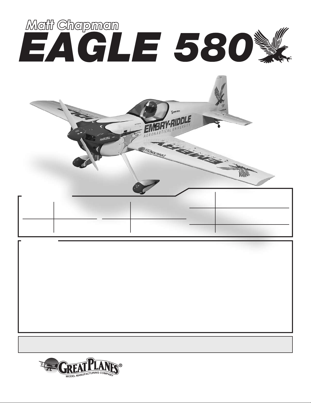
Page 1
Giant Scale 85 –100 cc Aerobatic/3D ARF
SPECIFICATIONS
Wingspan:
100 in
[2540mm]
Weight:
24 – 28 lb
[10880-12700 g]
Length: 96 in
[2440mm]
Radio: 4-5 channel with
9 standard size servos
Wing Area: 1892 sq in
[122 dm
2
Wing
]
Loading:
29– 34 oz / ft
[88– 104 g /dm2]
2
Engine: 85 – 100cc gasoline
WARRANTY
Great Planes® Model Manufacturing Co. guarantees this kit to
be free from defects in both material and workmanship at the
date of purchase. This warranty does not cover any component
parts damaged by use or modification. In no case shall Great
Planes’ liability exceed the original cost of the purchased kit.
Further, Great Planes reserves the right to change or modify this
warranty without notice.
In that Great Planes has no control over the final assembly or
material used for final assembly, no liability shall be assumed nor
accepted for any damage resulting from the use by the user of
the final user-assembled product. By the act of using the
user-assembled product, the user accepts all resulting liability.
If the buyer is not prepared to accept the liability associated
with the use of this product, the buyer is advised to return
READ THROUGH THIS MANUAL BEFORE STARTING CONSTRUCTION. IT CONTAINS IMPORTANT
INSTRUCTIONS AND WARNINGS CONCERNING THE ASSEMBLY AND USE OF THIS MODEL.
this kit immediately in new and unused condition to the
place of purchase.
To make a warranty claim send the defective part or item to
Hobby Services at the address below:
Hobby Services
3002 N. Apollo Dr. Suite 1
Champaign IL 61822 USA
Include a letter stating your name, return shipping address, as
much contact information as possible (daytime telephone
number, fax number, e-mail address), a detailed description of
the problem and a photocopy of the purchase receipt. Upon
receipt of the package the problem will be evaluated as quickly
as possible.
Champaign, Illinois
(217) 398-8970, Ext 5
airsupport@greatplanes.com
Entire Contents © Copyright 2009 GPMA1285 Mnl 2.0
Page 2
TABLE OF CONTENTS
INTRODUCTION
INTRODUCTION ................................2
AMA.........................................2
IMAA..........................................2
SAFETY PRECAUTIONS..........................3
DECISIONS YOU MUST MAKE .....................3
Radio Equipment...............................3
Engine Recommendations .......................4
ADDITIONAL ITEMS REQUIRED ...................4
Required Hardware and Accessories ...............4
Adhesives and Building Supplies ..................4
Optional Supplies and Tools ......................4
IMPORTANT BUILDING NOTES ....................5
KIT INSPECTION................................5
ORDERING REPLACEMENT PARTS ................5
KIT CONTENTS .................................6
ASSEMBLE THE STAB ...........................6
Prepare the Servo Arms .........................6
Mount the Elevator Servos .......................7
ASSEMBLE THE WING ...........................8
ASSEMBLE THE FUSE ...........................9
Install the Tail Gear .............................9
Attach the Rudder .............................10
Install the Rudder Servos .......................11
Install the Main Landing Gear ....................13
Mount the Engine .............................14
Assemble and Install the Fuel Tank................15
Install the Throttle & Choke Servos ................16
Install the Canister Mufflers (DA-100 only) ..........18
Install the Radio & Ignition Equipment .............19
Mount the Cowl ...............................20
FINAL ASSEMBLY ..............................22
Mount the Stabilizers...........................22
Mount the Wing ...............................22
Attach the Canopy.............................23
Apply the Decals ..............................23
GET THE MODEL READY TO FLY..................23
Check the Control Directions.....................23
Set the Control Throws .........................23
PROPER PUSHROD HOOKUP....................25
Balance the Model (C.G.) .......................26
Balance the Model Laterally .....................26
PREFLIGHT ...................................26
Identify Your Model ............................27
Charge the Batteries ...........................27
Balance Propellers ............................27
Ground Check ................................27
Range Check.................................27
ENGINE SAFETY PRECAUTIONS .................27
AMA SAFETY CODE (excerpts) ...................28
General .....................................28
Radio Control ................................28
CHECK LIST ..................................28
FLYING .......................................29
Fuel Mixture Adjustments .......................29
Takeoff......................................29
Flight . . . . . . . . . . . . . . . . . . . . . . . . . . . . . . . . . . . . . . . 29
Landing . . . . . . . . . . . . . . . . . . . . . . . . . . . . . . . . . . . . . 29
For the latest technical updates or manual corrections to
the Great Planes Giant Matt Chapman Eagle 580 ARF visit
the Great Planes web site at www.greatplanes.com. Open
the “Airplanes” link, then select the Great Planes Giant
Matt Chapman Eagle 580 ARF. If there is new technical
information or changes to this model a “tech notice” box will
appear in the upper left corner of the page.
AMA – Academy of Model Aeronautics
If you are not already a member of the AMA, please join!
The AMA is the governing body of model aviation and
membership provides liability insurance coverage, protects
modelers’ rights and interests and is required to fly at most
R/C sites.
Academy of Model Aeronautics Tele. (800) 435-9262
5151 East Memorial Drive Fax (765) 741-0057
Muncie, IN 47302-9252
Or via the Internet at:
http://www.modelaircraft.org
IMPORTANT!!!
Two of the most important things you can do to preserve the
radio controlled aircraft hobby are to avoid flying near fullscale aircraft and avoid flying near or over groups of people.
IMAA
The Great Planes Eagle 580 ARF is an excellent sportscale model and is eligible to fly in IMAA events. The
IMAA (International Miniature Aircraft Association) is an
organization that promotes non-competitive flying of giantscale models. If you plan to attend an IMAA event, obtain a
copy of the IMAA Safety Code by contacting the IMAA at
the address or telephone number below.
IMAA (913) 823-5569
205 S. Hilldale Road
Salina, KS 67401
Or via the Internet at:
http://www.fly-imaa.org/imaa/
sanction.html
2
Page 3

PROTECT YOUR MODEL, YOURSELF
& OTHERS..... FOLLOW THESE IM-
PORTANT SAFETY PRECAUTIONS
1. Your Great Planes Giant Matt Chapman Eagle 580 ARF
should not be considered a toy, but rather a sophisticated,
working model that functions very much like a full-size
airplane. Because of its performance capabilities, the
Great Planes Giant Matt Chapman Eagle 580 ARF, if not
assembled and operated correctly, could possibly cause
injury to yourself or spectators and damage to property.
We, as the kit manufacturer, provide you with a top quality,
thoroughly tested kit and instructions, but ultimately the
quality and flyability of your finished model depends
on how you build it; therefore, we cannot in any way
guarantee the performance of your completed model,
and no representations are expressed or implied as to the
performance or safety of your completed model.
Remember: Take your time and follow the instructions to end
up with a well-built model that is straight and true.
DECISIONS YOU MUST MAKE
2. You must assemble the model according to the
instructions. Do not alter or modify the model, as doing
so may result in an unsafe or unflyable model. In a few
cases the instructions may differ slightly from the photos.
In those instances the written instructions should be
considered as correct.
3. You must take time to build straight, true and strong.
4. You must use an R/C radio system that is in good condition,
a correctly sized engine, and other components as specified
in this instruction manual. All components must be correctly
installed so that the model operates correctly on the ground
and in the air. You must check the operation of the model and
all components before every flight. Inspect for signs of wear
in the flight controls and engine controls. You should also
cycle your radio batteries regularly and check to see that
they fulfill their current and capacity ratings.
5. If you are not an experienced pilot or have not flown this
size and type of model before, we recommend that you get
the assistance of an experienced pilot in your R/C club for
your first flights. If you’re not a member of a club, your local
hobby shop has information about clubs in your area whose
membership includes experienced pilots.
6. While this kit has been flight tested to exceed normal use,
it is important that the modeler understand that aerobatic
designs are not race planes, and should not be flown like
them. In addition, “more is better” is the WRONG philosophy
when powering an aerobatic plane. This model has been
professionally designed and tested, and the engine range
carefully selected for great performance. We strongly
recommend NOT exceeding the recommended engine range.
This is unsafe and will void the warranty of this model.
7. WARNING: The cowl and wheel pants included in this kit
are made of fiberglass, the fibers of which may cause eye,
skin and respiratory tract irritation. Never blow into a part
(wheel pant, cowl) to remove fiberglass dust, as the dust
will blow back into your eyes. Always wear safety goggles, a
particle mask and rubber gloves when grinding, drilling and
sanding fiberglass parts. Vacuum the parts and the work
area thoroughly after working with fiberglass parts.
This is a partial list of items required to finish the Great
Planes Giant Matt Chapman Eagle 580 ARF that may require
planning or decision making before starting to build. Order
numbers are provided in parentheses.
Radio Equipment
4–5 channel radio with:
o
• 1–2 Standard size servos
(throttle and optional choke servo)
• 8 - Standard size high torque metal geared
(150 oz/in) servos (2 for elevator, 4 for ailerons,
2 for rudder)
• 2 - 36" heavy duty servo extensions
(HCAM2726 for Futaba®) (outer aileron servos)
• 2 - 24" heavy duty servo extensions
(HCAM2721 for Futaba) (inner aileron servos)
• 2 - 40" heavy duty servo extensions
(FUTM4148 for Futaba) (elevator servos)
• 3 - Y-harnesses
(HCAM2751 for Futaba)
(aileron servos and rudder servos)
• 2 - 12" [300mm] servo extensions
(HCAM2711 for Futaba) (receiver to each wing)
• 1 - 24" [610mm] servo extension
(HCAM2721 for Futaba) (rudder servos)
• 1 - 36" [914mm] servo extension
(HCAM2726 for Futaba) (elevator servos)
• 1 - Receiver battery, 4200mAh 4.8V NiMH
(HCAM6335)
• 1 - Ignition battery, 2000mAh NiMH
(HCAM6321)
• 2 - Heavy duty switch harnesses
(FUTM4385) (Rx and ignition)
• 2 - Charge jacks
(ERNM3001 for Futaba)
If you’re not using a computer radio with mixing functions or
one with less than 6 channels, please consider purchasing
the following items:
3
Page 4

• 1 - Servo reverser lead
(FUTM4150 to reverse one elevator servo)
• 1 - Servo synchronizer
(FUTM4155 to synchronize inboard and outboard
aileron servos) (Note: If you’re using this, you won’t
need to order 2 of the Y-harnesses above)
Adhesives and Building Supplies
In addition to common household tools and hobby tools, this
is the “short list” of the most important items required to build
the Great Planes Giant Matt Chapman Eagle 580 ARF. Great
Planes Pro™ CA and Epoxy glue are recommended.
Engine Recommendations
The recommended engine size range for the Great Planes
Giant Matt Chapman Eagle 580 ARF is 85 – 100cc. This
manual will detail the installation of the DA-100 engine with
twin canister style exhaust. A mounting template and special
wooden standoff shims are provided for you if you choose to
install the DA-85 engine.
The following items should be ordered from Desert Aircraft
or your favorite hobby supplier if you choose the DA-100:
• DA-100 engine
• Standard DA-100 muffler set
OR
• MTW canister exhaust (short version) (DA model
number TD 75K)
• MTW headers
The following items should be ordered from Desert Aircraft
or your favorite hobby supplier if you choose the DA-85:
• DA-85 engine
• Slimline Pitts muffler for DA-85
OR
• JTEC large wrap around Pitts muffler for DA-85
(JTCG7985) (standard option)
OR
• JTEC X-large wrap around Pitts muffler for DA-85
(JTCG2085) (quiet option)
• 1 oz. [30g] Thin Pro CA (GPMR6002)
• 1 oz. [30g] Medium Pro CA+ (GPMR6008)
• Pro 30-minute epoxy (GPMR6047)
• Pro 6-minute epoxy (GPMR6045)
• Threadlocker thread locking cement (threadlocker)
(GPMR6060)
• R/C-56 glue 4oz (JOZR5007)
• Drill bits: 1/16" [1.6mm], 5/16" [7.9mm], 1/8" [3.2mm],
3/16" [4.8mm]
• X-long (jobber length) drill bit: 3/16" [4.8mm]
• 10-piece standard tap and drill set (GPMR8108)
• Tap handle (GPMR8120)
• Small metal file
• Velcro
®
hook & loop (1" x 6" [25 x 150mm],
(GPMQ4480)
• 3/8" Heat shrink tubing (GPMM1060)
• Stick-on segmented lead weights (GPMQ4485)
• #1 Hobby knife (HCAR0105)
• #11 blades (5-pack, HCAR0211)
• Single-edge razor blades (10-pack, HCAR0212)
• Medium T-pins (100, HCAR5150)
• Sandpaper assortment
• Petroleum jelly
• Hobby torch (HCAR0765)
• Silver solder kit (STAR2000)
Optional Supplies and Tools
Here is a list of optional tools mentioned in the manual that
will help you build the Great Planes Giant Matt Chapman
Eagle 580 ARF.
ADDITIONAL ITEMS REQUIRED
Required Hardware and Accessories
In addition to the items listed in the “Decisions You Must
Make” section, the following is a list of hardware and
accessories required to finish the Great Planes Giant
Matt Chapman Eagle 580 ARF. Order numbers are
provided in parentheses.
• Propeller (per the engine manufacturer’s suggestion)
• R/C foam rubber 1/4" [6.4mm] – (HCAQ1000)
• Two packs of 3’ [914mm] Tygon
(DUBQ0427)
®
gasoline fuel tubing
• 4 oz. [113g] aerosol CA activator (GPMR634)
• CA applicator tips (HCAR3780)
• CA debonder (GPMR6039)
• Epoxy brushes (6, GPMR8060)
• Mixing sticks (50, GPMR8055)
• Mixing cups (GPMR8056)
• Pliers with wire cutter (HCAR0630)
• Robart Super Stand II (ROBP1402)
• Masking tape (TOPR8018)
• Denatured alcohol (for epoxy clean up)
• Rotary tool such as Dremel
®
• Rotary tool reinforced cut-off wheel (GPMR8200)
• Quick drill set (HCAR0699)
• 3M ScotchBrite
• Top Flite
®
®
green abrasive pad
MonoKote® sealing iron (TOPR2100)
• Top Flite MonoKote trim seal iron (TOPR2200)
• Top Flite MonoKote heat gun (TOPR2000)
4
Page 5
IMPORTANT BUILDING NOTES
KIT INSPECTION
There are several types of screws used in this kit:
•
Self-tapping or sheet metal screws
are designated by a number and a
length. For example, #6 x 3/4" [19mm].
Machine screws are designated by a
number, threads per inch, and a length.
For example, 4-40 x 3/4" [19mm].
Socket Head Cap Screws (SHCS) are
designated by a number, threads per
inch, and a length. For example, 4-40 x
3/4" [19mm]
• When you see the term test fit in the instructions, it means
that you should first position the part on the assembly
without using any glue. Then, slightly modify or custom
fit the part as necessary for the best fit.
• Whenever the term glue is written you should rely upon
your experience to decide what type of glue to use. When
a specific type of adhesive works best for that step, the
instructions will make a recommendation.
• Whenever just epoxy is specified you may use either
30-minute (or 45-minute) epoxy or 6-minute epoxy. When
30-minute epoxy is specified it is highly recommended that
you use only 30-minute (or 45-minute) epoxy, because you
will need the working time and/or the additional strength.
• Photos and sketches are placed before the step they
refer to. Frequently you can study photos in following steps
to get another view of the same parts.
• The Great Planes Giant Matt Chapman Eagle 580 is
factory-covered with Top Flite MonoKote film. Should
repairs ever be required, MonoKote can be patched with
additional MonoKote purchased separately. MonoKote is
packaged in six-foot rolls, but some hobby shops also sell
it by the foot. If only a small piece of MonoKote is needed
for a minor patch, perhaps a fellow modeler would give
you some. MonoKote is applied with a model airplane
covering iron, but in an emergency a regular iron could
be used. A roll of MonoKote includes full instructions for
application. Following are the colors used on this model
and order numbers for six foot rolls.
Cub Yellow TOPQ0220
Sapphire Blue TOPQ0227
Missile Red TOPQ0201
Orange TOPQ0202
Black TOPQ0208
• The stabilizer and wing incidences and engine thrust
angles have been factory-built into this model. However,
some technically-minded modelers may wish to check
these measurements anyway. To view this information
visit the web site at www.greatplanes.com and click on
“Technical Data.” Due to manufacturing tolerances which
will have little or no effect on the way your model will fly,
please expect slight deviations between your model and
the published values.
Before starting to build, take an inventory of this kit to make
sure it is complete and inspect the parts to make sure they
are of acceptable quality. If any parts are missing or are not of
acceptable quality, or if you need assistance with assembly,
contact Product Support. When reporting defective or
missing parts, use the part names exactly as they are written
in the Kit Contents list.
Great Planes Product Support (217) 398-8970, ext. 5
3002 N Apollo Drive, Suite 1 Fax: (217) 398-7721
Champaign, IL 61822
E-mail: airsupport@greatplanes.com
ORDERING REPLACEMENT PARTS
Replacement parts for the Great Planes Giant Matt Chapman
Eagle 580 ARF are available using the order numbers in
the Replacement Parts List that follows. The fastest, most
economical service can be provided by your hobby dealer or
mail-order company.
To locate a hobby dealer, visit the Great Planes web site
at www.greatplanes.com. Choose “Where to Buy” from the
menu on the left side of the page. Follow the instructions
provided on the page to locate a U.S., Canadian or
International dealer.
Parts may also be ordered directly from Hobby Services by
calling (217) 398-0007, or via facsimile at (217) 398-7721,
but full retail prices and shipping and handling charges will
apply. Illinois and Nevada residents will also be charged
sales tax. If ordering via fax, include a Visa® or MasterCard®
number and expiration date for payment.
Mail parts orders Hobby Services
and payments by 3002 N Apollo Drive, Suite 1
personal check to: Champaign IL 61822
Be certain to specify the order number exactly as listed in the
Replacement Parts List. Payment by credit card or personal
check only; no C.O.D.
If additional assistance is required for any reason contact
Product Support by e-mail at productsupport@greatplanes.
com, or by telephone at (217) 398-8970.
Giant Eagle 580 ARF Replacement Parts List
GPMA3355 Fuselage GPMA3362 Decals
GPMA3356 Wing Set GPMA3363 Wing Tube
GPMA3357 Hor. Stab. Set GPMA3364 Stabilizer Tubes
GPMA3358 Rudder GPMA3365 Hatch/Canopy
GPMA3359 Cowl GPMA3367 Pilot
GPMA3360 Landing Gear GPMA3368 Fuel Tank
GPMA3361 Wheelpants
5
Page 6
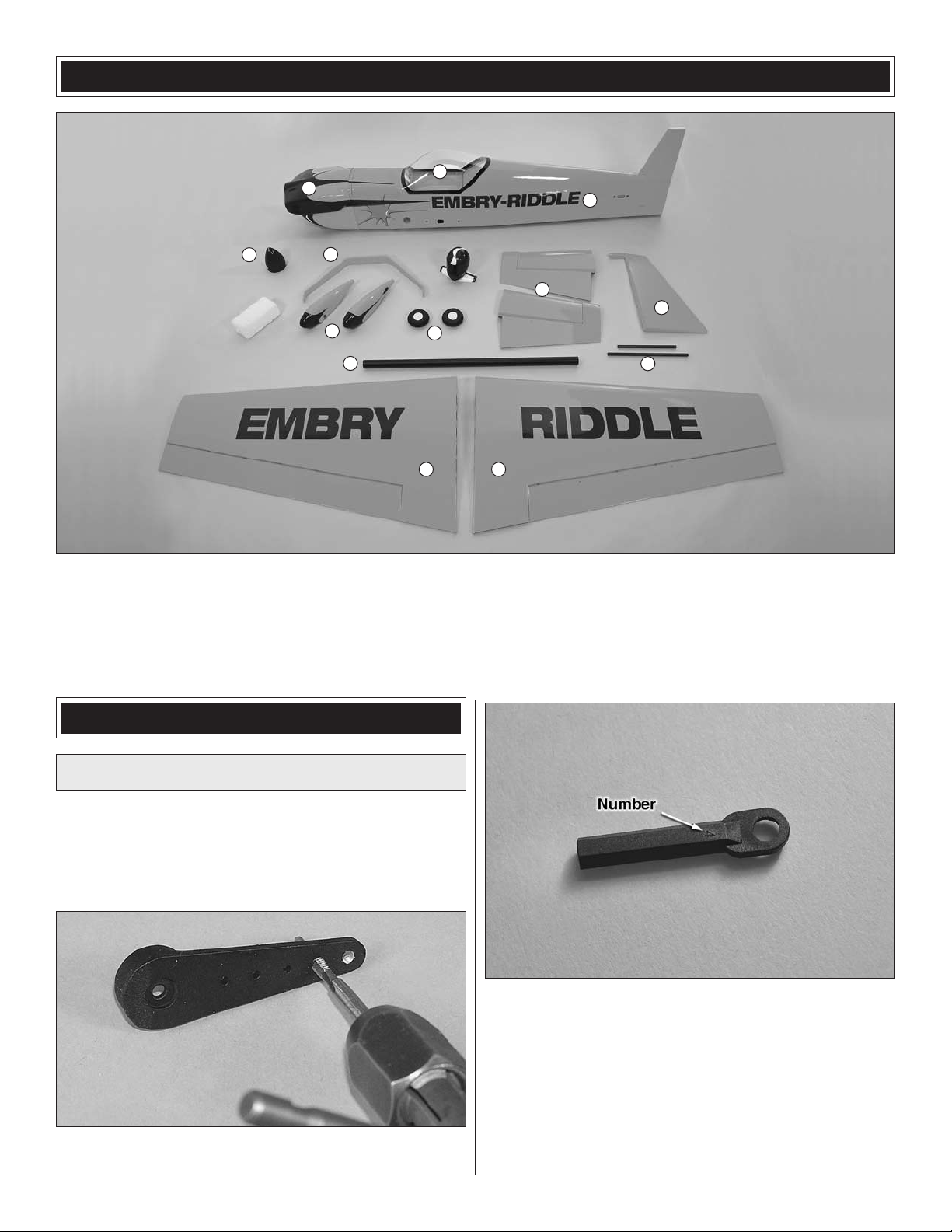
KIT CONTENTS
3
1
2
4
5
7
12
1. Cowl
2. Fuselage
3. Canopy/Hatch
4. Aluminum Spinner
8
6
11 11
5. Main Gear
6. Wheels
7. Wheel Pants
8. Stab and Elevators
10
9
9. Stab Tubes
10. Rudder
11. Wings and Ailerons
12. Wing Tube
ASSEMBLE THE STAB
Prepare the Servo Arms
Note: The included aluminum servo arms are designed with
plastic inserts, allowing the arms to work with all current
Futaba, Hitec, Airtronics and JR servos. The inserts are also
designed so that the centering of the arm can be adjusted by
rotating the insert and then re-attaching the arm.
1. Drill and tap 4-40 threads in the two outermost holes of
o
each of the six single-sided servo arms.
2. The nylon ball links have a number on one side of them.
o
With the number facing up, press the brass ball into each of
the nylon balls link from the bottom, opposite the number.
6
Page 7
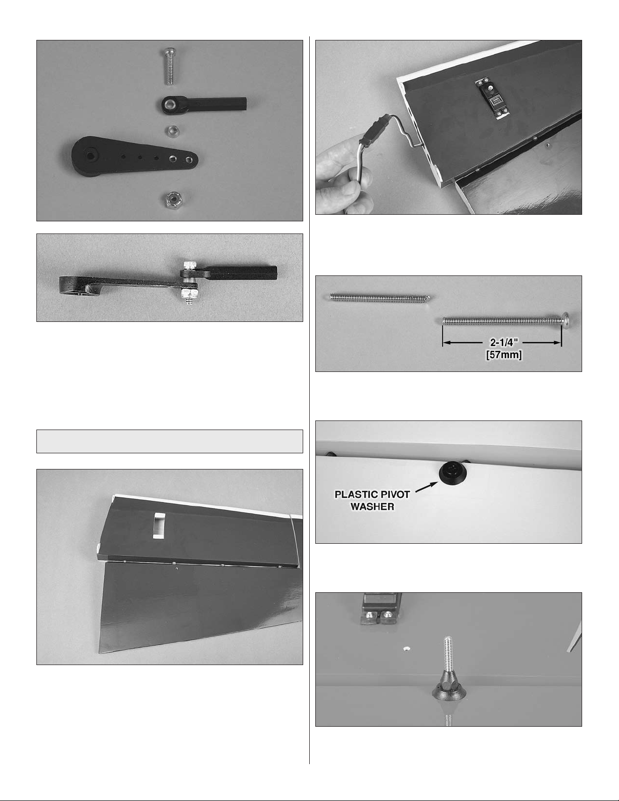
3. Attach the ball link to the outer tapped hole of one of
o
the one-sided servo arms with 4-40 x 1/2" [13mm] Socket
Head Cap Screw [SHCS] brass stand off and 4-40 lock nut.
Note: The number goes down toward the servo arm.
4. Attach the ball links to one other single-sided
o
servo arm.
Mount the Elevator Servos
3. Attach a 40" [1016mm] heavy duty servo lead
o o
extension and secure it using 3/8" [9.5mm] diameter heat
shrink tubing.
4. Cut the 4" [102mm] control horn bolt to a length of
o o
2-1/4" [57mm].
1. Trim the covering from the servo bay in the stab.
o o
2. Use a 1/16" [1.6mm] drill bit to make the holes and
o o
install the elevator servo to a stab half using the hardware
provided with your servo. Remove the screws and harden
the screw holes you created in the wood with thin CA. You
should do this each time you thread into wood.
5. Place a pivot washer on the control horn bolt. Install
o o
the control horn bolt through the top of the elevator.
6. Install a pivot washer to the other side and screw the
o o
nylon nut onto the control horn bolt.
7
Page 8
7. Assemble the control horn parts as shown. Note:
o o
Eight total control horn pivots are supplied. Two are
standard thread and six are reverse thread. Identify the
two standard thread pivots and set them aside for use on the
rudder system. Do not assemble those now.
11. Plug the servo into the receiver and turn the
o o
radio on.
12. Place the appropriate servo arm adapter on the
o o
servo. The inserts have letters stamped on the bottom of
them (A=Airtronics/JR, F=Futaba, H=Hitec).
13. Attach the aluminum servo arm to the servo so
o o
that it is 90 degrees to the long side of the servo case. If it
is not, remove the servo arm, rotate the insert 90 degrees
and attach the servo arm again. Use the insert position that
makes the servo arm fit closest to 90 degrees. Be sure to
secure the servo arm with the screw.
8. Screw the reverse threaded end of the 2-1/2"
o o
[64mm] pushrod 15 full turns into the control horn. (To
tighten, turn counterclockwise.)
9. Screw the “normal” threaded end of the pushrod 15
o o
turns into the ball link that is connected to one of the singlesided servo arms.
14. Adjust the pushrod by turning it until the elevator is
o o
centered on the stab.
15. Repeat steps 1-14 for the other stab half.
o
ASSEMBLE THE WING
1. Remove the covering from the two servo openings
o o
in the bottom of the wing.
10. Screw the control horn onto the control horn
o o
bolt, leaving 1/16" [1.6mm] extending from the top of the
control horn.
2. Connect a 24" [610mm] heavy duty servo lead
o o
extension to the inboard aileron servo and a 36" [914mm]
extension to the outboard aileron servo. Secure the
connections with heat shrink tubing.
8
Page 9
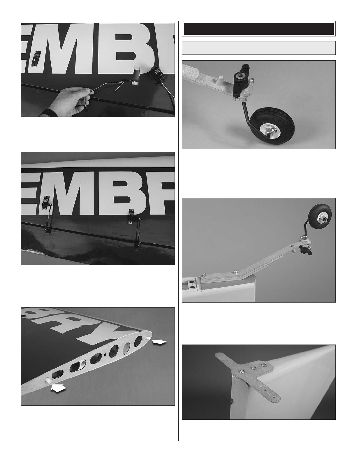
3. Use the string in the wing to route each servo lead
o o
through the wing. Mount the servos, noting that the servo
arms go toward the trailing edge of the wing.
ASSEMBLE THE FUSE
Install the Tail Gear
1. Grind flat spots on the tail gear wire for the set
o
screws. Assemble the tail gear as shown in the photo with
threadlocker. Use three 3mm wheel collars, three 3mm x
5mm phillips head screws and one 3mm x 8mm phillips head
screw to assemble it.
4. Mount the control horns and servo arms following the
o o
same steps used with the stab. Mount the ball link to the inner
tapped hole on the aileron servo arms. Cut the 4" [102mm]
control horn bolts down to a length of 2-1/4" [57mm].
5. Glue the white nylon anti-rotation dowels in the wing
o o
with epoxy.
6. Repeat steps 1-5 for the other wing.
o o
2. Remove the covering for the tail gear mounting bolts.
o
Attach the tail gear with threadlocker, two 4-40 x 3/4" [19mm]
phillips head screws, two #4 flat washers, and two #4 lock
washers.
3. Attach the tail gear steering arm to the bottom of the
o
rudder with three #4 x 5/8" [15.9mm] sheetmetal screws.
9
Page 10
Attach the Rudder
1. Mount the rudder control horns as shown, using the
o
remaining uncut 4" [102mm] bolt.
4. Coat the hinge barbs with glue.
o
2. Prepare the five hinges by cleaning the barbs with
o
denatured alcohol and applying household oil or petroleum
jelly to the hinge pins.
3. Mix up a batch of 30-minute epoxy (or your
o
preferred hinge glue) and use a toothpick to fill the predrilled hinge pockets with glue. Fill the rudder and the
fin pockets with glue.
5. Install the hinges and the rudder with the hinge pins
o
aligned vertically. Rotating the hinges 90° when you fit them
to the rudder will help you do this. Deflect the rudder left and
right several times as you slide the rudder onto the hinges.
10
Page 11

6. When the rudder hinges are fully cured, attach the tail
o
gear arm to the tail gear with the two springs.
Install the Rudder Servos
3. Using silver solder, flux and your hobby torch, solder
o
an unthreaded steel clevis onto the unthreaded end of each
pushrod so that 1/4" [6.4mm] of rod protrudes past the barrel
of the clevis. Wipe away the remaining flux with a damp cloth
while the joint is still warm to prevent corrosion. Apply a thin
film of household oil to the surface of the joint.
4. Fit a 4-40 hex nut, two silicone retainers and a 4-40
o
threaded clevis onto the threaded end of each rod. Adjust
the length of the rods so that they measure 3" [76mm] from
pin to pin.
1. Install two servos in the rudder tray so that the servo
o
output shafts are positioned aft.
2. Cut the two 4-40 x 4-1/2" [114mm] one-end threaded
o
rods down so that they each measure 1-3/4" [44mm].
Roughen the end of the rod with a green ScotchBrite pad
or sandpaper. Clean the rod with denatured alcohol and a
clean cloth.
5. Drill and tap one of the two 4" [102mm] servo arms and
o
install two nylon ball links as shown. Link the two servo arms
together by installing the pushrods in the fourth holes out
from the center of each arm.
11
Page 12

6. Cut the supplied steel pull-pull cable in half. Swage a
o
threaded coupler to one side of each of the two cables. Note:
The swage must be crimped tightly! Inspect each swage for
cracks and to assure tightness.
7. Thread the couplers into the nylon clevises so that at
o
least 1/2" [12.7mm] of thread is still showing.
9. Turn on your radio and fit the servo arms to the rudder
o
servos. Make adjustments using your radio or a servo
synchronizer to balance the two servos. Make sure that you
have not twisted the cables and that they slide freely through
the tubes. Install the servo arm screws using threadlocker.
10. Install a threaded coupler onto each standard
o
thread control horn pivot. Screw them in so that at least 1/2"
[12.7mm] of thread is still showing.
8. Route the cables through the guide tubes.
o
11. Temporarily fit the control horn pivots to the control
o
horns. Do not install the cotter pin until after you have
adjusted and tensioned both cables. With your radio still
on and your rudder servos centered, fit both cables to the
couplers and center the rudder. When you’re satisfied, swage
the cables to the couplers. Trim the excess cable.
12
Page 13

12. Tension and adjust the cables at the couplers by
o
removing the control horn pivot pin and tightening or
loosening the pivot on the coupler. Note: It is necessary to
adjust the cable tension in this manner to prevent the cable
from becoming twisted.
13. Reinstall the control horn pivots. Make sure that at
o
least 3/16" [4.8mm] of thread is showing at each of the four
cable couplers. Install the washers and cotter pins to the left
and right rudder control horn pivot pins.
3. Mount the wheel pant with two 8-32 x 3/4" [19mm]
o o
SHCS. Center the wheel in the wheel pant and tighten the
wheel collars.
4. Remove the wheel pant. Mark the location of the wheel
o o
collars. File flat spots on the axles for the wheel collars.
5. Apply threadlocker to the wheel collar locking screws
o o
and refit the wheel to the axle. Mount the wheel pant using
threadlocker, two 8-32 x 3/4" [19.1mm] SHCS, two #8 flat
washers and two #8 lock washers.
6. Repeat steps 1 through 5 for the other axle and
o
wheel pant.
14. Tighten the 4-40 nuts against the threaded clevises to
o
secure the pushrods, using threadlocker.
Install the Main Landing Gear
1. Attach the axle to the main gear with the nylon lock
o o
nut.
2. Fit the wheel to the axle using two wheel collars with
o o
two 6-32 x 1/4" [6.4mm] SHCS locking screws.
7. Mount the landing gear to the fuse with threadlocker,
o
four 8-32 x 1" [25.4mm] SHCS, four #8 flat washers and four
#8 lock washers.
13
Page 14

Mount the Engine
We have made provisions to mount either the DA-85 or the
DA-100 gas engine from Desert Aircraft. This section of the
manual will guide you in installing the DA-100 along with the
optional short canister-style exhaust. Laser-etched marks
have been made on the firewall that match the mounting
pattern of the DA-100. If you will be using a DA-85 engine,
please use the mounting template we have provided for you
in the back of this manual and refer to steps 6 through 9.
Note: The DA-85 must be used with the standard Pitts style
muffler. Canister or tuned pipe exhaust cannot be used on
this model with the DA-85.
3. For the DA-100 engine, drill four 5/16" [7.9mm] diameter
o
holes using the laser-etched marks provided on the firewall.
To get the straightest holes, you can drill 1/8" [3.2mm] pilot
holes first.
1. If you’re using the DA-100 and will be using canister
o
exhaust, remove the cover for the exhaust tunnel. If not, you
may glue the cover in place.
2. Tighten the ten bracing screws on the firewall. You
o
should periodically check these from time to time to make
sure that they stay tight. If you prefer, epoxy them in place.
4. Install four 1/4-20 blind nuts on the back side of the
o
firewall.
5. Mount the engine to the firewall using threadlocker,
o
twenty 6mm thick aluminum spacers (five per mounting
leg), four 1/4-20 x 2-3/4" [70mm] SHCS bolts, and four 1/4"
14
Page 15

[6.4mm] lock washers. You’ll want to inspect these screws
2mm & 3mm
Thicknesses
Ten
Notched Ply
Spacers
DA-85 Engine
Plywood Shim
Stackup
(Allow carb
adjustment)
Four
Closed Ply
Spacers
after the first few flights and then periodically after that to
make sure that they’re still tight.
Use the next four steps to mount a DA-85 engine.
Mounting and rigging the DA-85 engine is similar to the DA100 with the exception of the required engine mount standoffs.
Desert Aircraft does not allow the use of aluminum standoffs
for this particular engine. We have supplied you with eighteen
wooden standoffs to accommodate your DA-85.
6. Cut out the DA-85 mounting template we have provided
o
in the back of this manual. Tape (or use spray adhesive) the
template in position with the arrow pointed up, the text toward
you, and the crosshairs aligned with their corresponding
marks on the firewall.
7. Drill four 5/16" [7.9mm] diameter holes for the engine
o
mounting bolts. Install four 1/4-20 blind nuts on the back side
of the firewall.
8. Use the sketch above to help you stack the ply standoffs
o
in the correct order. Four closed standoffs go on either side of
the ten notched standoffs. Coat the threads and the shank of
the four 1/4-20 x 2-3/4" [70mm] SHCS bolts with petroleum
jelly and fit a 1/4" lock washer to each. Apply a thin layer of
30-minute epoxy between each layer and bolt your DA-85 to
the firewall.
9. After the epoxy has cured, remove the engine and
o
clean off the bolt threads. Fuel proof the plywood standoffs
with finishing resin or thinned epoxy. Reinstall the engine
applying threadlocker to the engine mounting bolt threads.
Assemble and Install the Fuel Tank
1. Assemble the stopper, brass tubes and steel stopper
o
end plates as shown.
15
Page 16

2. Solder the brass barbs to the ends of the brass tubes.
“Hook” Side
“Loop” Side
Cut the Velcro to the correct
length and join the pieces
together to make a strap.
o
Note: Get the tubes just hot enough for the solder to flow. If
you get the tubes too hot it will damage the tank stopper.
3. Attach the clunks to the short brass tubes with 5"
o
[127mm] pieces of fuel line. Secure the fuel lines to the barbs
with four small plastic cable ties.
6. Make two more straps and attach your fuel tank to the
o
tray. Be sure the vent line faces up. Attach three fuel lines
using small cable ties to secure them to the lines. The vent
and fill lines should be at least 16" [406mm] and the catb line
should be at least 14" [356mm]. Label each fuel line to make
it easy to identify. The tabs of the tray fit into the slots of the
former in the fuse. Note: The tray can be flipped over to offset
the tank to the side that will clear the throttle linkage. Install
the fuel tank tray using six #2 x 3/8" [9.5mm] Phillips head
sheet metal screws and six #2 washers.
4. Install the aluminum neck ring. Install the stopper
o
assembly in the tank with the vent line toward one of the
longer sides of the tank. Mark that side of the tank as top.
Tighten the stopper screw.
5. Wrap your ignition battery in 1/4" [6.4mm] latex foam
o
rubber. Cut a section of hook and loop material and make
a battery strap as shown in the sketch. Securely install
your ignition battery on the fuel tank tray using the strap
you made.
Install the Throttle & Choke Servos
1. Fit a steel ball link to your throttle arm using
o o
threadlocker and a 2-56 hex nut.
2. Drill a 3/16" [4.8mm] hole through the former aligned
o o
with the throttle arm on the engine.
16
Page 17

3. Assemble the throttle and choke servo tray as
o o
shown. Note: Two triangle support pieces are supplied to
support the tray. Please glue these in later after you have
installed the tray in the fuse.
4. Assemble the two pushrod standoffs as shown.
o o
Four other standoffs are provided for you as well as spacers
so you can suppor t the throttle and choke pushrod tubes
as needed.
6. Lightly sand the outside of the 36" [914mm] throttle
o o
outer pushrod tube. Route the tube and fit the standoffs. Cut
the tube to length.
7. Screw a 2-56 x 6" [152mm] one-end threaded rod
o o
into a 36" [914mm] flexible inner pushrod tube. Make a 90°
bend in the unthreaded end of the rod to help you screw the
rod in. Screw it in so that most of the threads are engaged.
5. Install the servo tray and your throttle servo. Note:
o o
The servo tray can be offset to the right or left to suit your
installation. Install the two triangle supports accordingly.
8. Cut the steel rod down so that it measures 1-1/2"
o o
[38mm] from the end of the plastic tube. Solder a brass
threaded coupler onto the end of the pushrod. Thread on
a 2-56 hex nut, a silicone retainer, and a steel clevis. Note:
A soldering iron should not be used as this is too slow to
heat the joint and will cause the pushrod tube to melt. Use a
hobby torch with only enough heat to get the solder to flow.
17
Page 18

9. Install the throttle rod and attach the clevis to your
o o
servo arm. Install the servo arm locking screw.
Install the Canister Mufflers (DA-100 only)
This section covers the installation of the optional MTW
short canister exhaust system for the DA-100. This airplane
was designed around this particular system, but other
short canisters may fit. As is, the model will accommodate
twin 70mm diameter cans whose can lengths are no
longer than 250mm.
As a word of caution, canister style exhaust must not
be considered maintenance free. Periodic inspection is
required (especially after the first few runs and flights). The
sixteen silicone supports must be replaced when heat has
deteriorated them. Also, the cans should be removed from
time to time to check the surrounding wood support and box
structure for damage, failed glue joints, and dry or charred
wood. For a more maintenance free system, please use the
standard mufflers for your DA-100.
10. With your radio on and your throttle servo and
o o
throttle set to full open, cut the pushrod to length. Thread a
1" [25.4mm] threaded rod and a nylon ball link socket onto
the engine side of the pushrod. Attach the ball link.
11. Test the operation of your throttle and adjust as
o o
necessary. Tighten the 4-40 locking nut on the servo arm
side of the throttle pushrod.
12. Repeat steps 1 through 11 to install your choke
o o
servo and linkage. When you’re satisfied with the operation of
your throttle and choke setup, permanently glue all pushrod
standoffs in place and use the provided #2 x 3/8" [9.5mm]
sheetmetal screws and #2 washers to screw the two large
throttle rod standoffs to the tank tray.
1. Inspect the silicone supports and replace any that
o
appear damaged, loose, or are otherwise unusable. These
can be replaced by using any standard silicone glow fuel line.
2. Fit the canister into one of the fuse supports. Slide
o
it all the way back until it stops, and then slide it forward
about 1-1/2" [38mm] so that the end of the front pipe is 1/2"
[12.7mm] forward of the firewall face. Do the same for the
other canister.
18
Page 19

3. Position the exhaust header over the right cylinder’s
o o
exhaust port and mark the pipe about 1-1/4" [32mm] forward
of the firewall face. Use a felt tip pen to label this as the right
hand pipe.
4. Cut the pipe to length.
o o
Install the Radio & Ignition Equipment
1. Four total positions are provided for you to mount your
o
radio and ignition switches. Please trim the covering from the
switch plates that suit your application. Note: To minimize the
potential for radio interference, all engine ignition equipment
(battery and switch included) must be kept at least 10"
[254mm] from all radio equipment and servos.
5. Fit the header to the canister using a coupler and
o o
two spring clamps. Bolt the header to the cylinder using the
hardware and any gasket that came with your engine.
6. Repeat steps 3 through 5 for the other cylinder.
o o
7. Trim the covering over the six cooling ports. Note: This
o
is not an optional step. Muffler canisters require a generous
amount of cooling air flowing over them to prevent damage
to the surrounding structure.
2. Install the switches and charge jacks. Depending on
o
the switch and charge jack you choose, you may have to
enlarge the openings in the fuse.
3. Wrap your radio battery in 1/4" [6.4mm] latex foam
o
rubber and install it to the radio equipment tray. Install your
radio equipment, hookup your servos, and install any other
radio devices (servo synchronizer, servo reverser, etc.).
Route your receiver antenna through the tube provided.
19
Page 20

7. Install the fill line plug.
o
4. Secure your battery leads with 3/8" [9.5mm] heat
o
shrink tubing.
5. Install your ignition module away from any radio
o
equipment. Secure the electrical connections with heat
shrink tubing. Make sure that the spark plug leads will not
chafe by supporting them with plastic cable ties.
Mount the Cowl
1. Apply a 6" [152mm] piece of masking tape over each
o
of the six pre-installed blind nuts for the cowl. Each piece
of tape should extend straight back and be parallel with the
top edge of the fuse. Use cardstock or a manila envelope
to make templates for your mufflers or cylinder head if
necessary. Tape the templates in place on the fuse.
6. Route your vent and fill lines out the bottom of the fuse.
o
Connect the feed line to the carburetor and secure it with a
small cable tie.
2. Draw a straight line from the center of the blind nut
o
hole back about 5" [127mm]. Make a mark at the hole and
5" [127mm] back.
20
Page 21

3. Slide the cowl over the engine onto the fuselage. On
o
the DA-100 you need to remove one of the two spark plug
boots to get the cowl on.
4. Cut a cooling slot at the bottom of the cowl that matches
o
the air exit slot in the fuse.
7. Drill a 1/8" [3.2mm] hole at each mark and reinstall the
o
cowl using six 4-40 x 1/2" [12.7mm] SHCS, six #4 lockwashers,
and six flat washers. Don’t forget to use threadlocker.
8. Install the spinner and a balanced prop.
o
5. Fit the spinner backplate and position the cowl 1/8"
o
[3.2mm] behind the spinner backplate. Center the cowl with
the backplate and tape it in position.
6. Align a ruler with the lines you made and measure 5"
o
[127mm] forward to the cowl. Mark the cowl for each blind
nut. Remove the cowl.
21
Page 22

FINAL ASSEMBLY
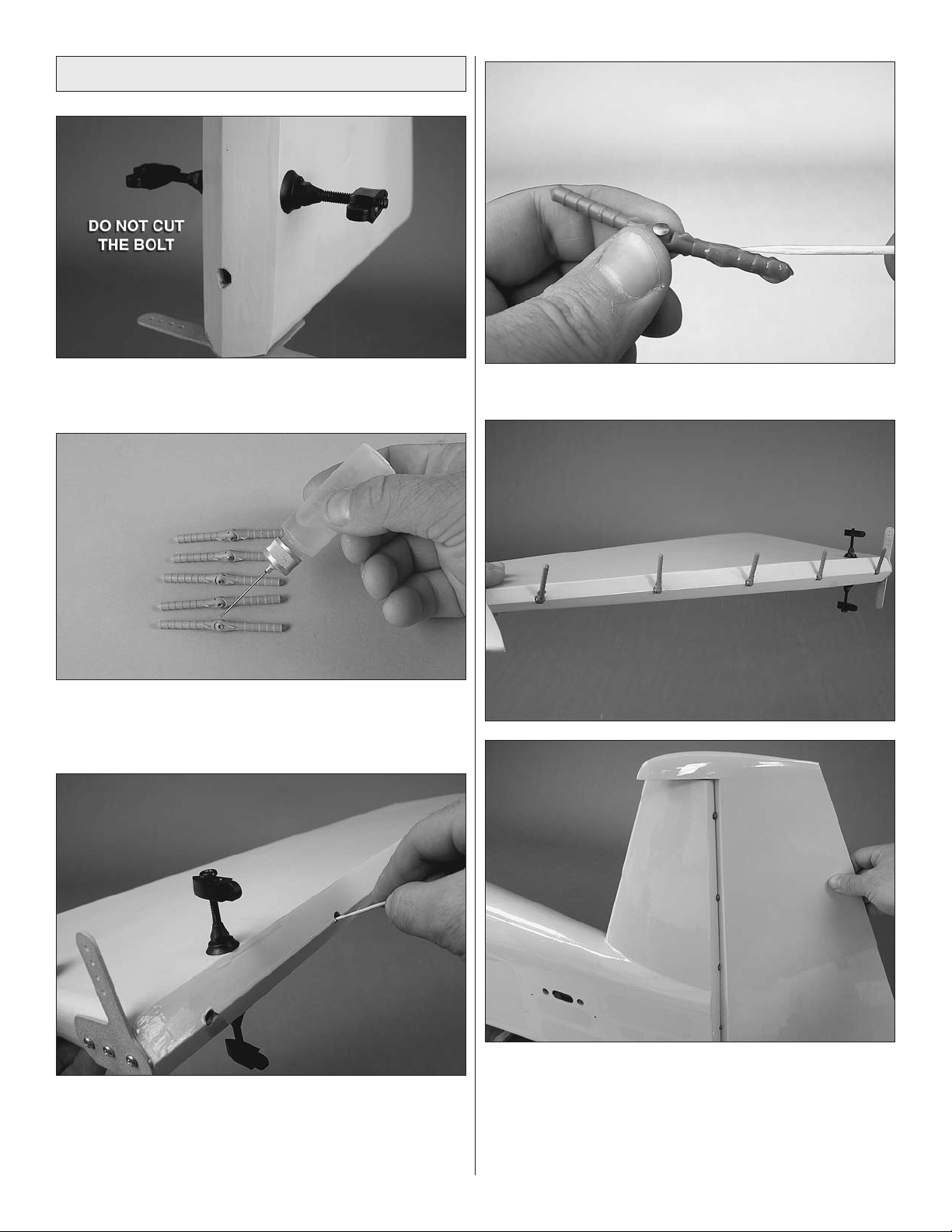
Mount the Stabilizers
The removable tail needs to be checked often for wear. If the
tail develops excessive movement, thin CA sparingly applied
to the inside of the stab tubes and root ribs will cure it. If you
are able to transport the Eagle with the stabs installed, we
recommend permanently attaching the stab to the fuse with
epoxy. If you permanently install the stab, please be sure to
also use threadlocker on the mounting screws and check to
see that these are still in place before each flight.
4. Install the stab halves using threadlocker, four 4-40 x
o
3/4" [19mm] phillips head screws, four #4 lock washers, and
four #4 washers. Make sure that the root rib of the stab sits
flat against the fuse side. If it doesn’t, remove the stabs and
try installing the tubes into the opposite stab half first.
Mount the Wing
1. Fit the carbon stab tubes to one stab half. The shorter
o
tube goes in the front. Rotate the tube as you’re inserting it
and push each tube in until it stops.
2. Fit the stab half to the fuse. Route the servo lead
o
through the plastic guide tube inside the fuse.
1. Fit the wing tube to one wing. Slide the wing and tube
o
into the fuse. Guide your aileron servo leads into the fuse.
2. Fit the other wing. Make sure both wings sit flush
o
against the fuse sides.
3. Fit the other stab half and route its lead. Pull both leads
o
through as you insert the stabs.
3. Secure each wing using one 1/4-20 nylon wing bolt.
o
22
Page 23

Attach the Canopy
FULL
THROTTLE
RUDDER
MOVES
RIGHT
ELEVATOR
MOVES DOWN
RIGHT AILERON
MOVES UP
LEFT AILERON
MOVES DOWN
4-CHANNEL RADIO SETUP
(STANDARD MODE 2)
1. Attach the pilot to the canopy frame using two 4-40 x
o
1/2" [12.7mm] SHCS, #4 flat washers and #4 lock washers.
Use threadlocker on the screws.
2. Mount the canopy to the fuselage with four 4-40 x
o
3/4" [19.1mm] SHCS, #4 flat washers and #4 lock washers.
Periodically coat the screw threads with threadlocker.
2. With the transmitter and receiver still on, check all the
o
control surfaces to see if they are centered. If necessary,
adjust the clevises on the pushrods or the cables to center
the control surfaces.
Apply the Decals
1. Remove the decals from the sheet.
o
2. Be certain the model is clean and free from oily
o
fingerprints and dust. Prepare a dishpan or small bucket with
a mixture of liquid dish soap and warm water—about one
teaspoon of soap per gallon of water. Submerse the decal
in the soap and water and peel off the paper backing. Note:
Even though the decals have a “sticky-back” and are not the
water transfer type, submersing them in soap & water allows
accurate positioning and reduces air bubbles underneath.
3. Position decal on the model where desired, using the
o
picture on the box as a guide. Hold the decal down and use
a paper towel to wipe most of the water away.
o
squeegee remaining water from under the decal. Apply the
rest of the decals the same way.
4. Use a piece of soft balsa or something similar to
GET THE MODEL READY TO FLY
Check the Control Directions
1. Turn on the transmitter and receiver and center the
o
trims. If necessary, remove the servo arms from the servos
and reposition them so they are centered. Reinstall the
screws that hold on the servo arms.
3. Make certain that the control surfaces and the carburetor
o
respond in the correct direction as shown in the diagram.
If any of the controls respond in the wrong direction, use
the servo reversing in the transmitter to reverse the servos
connected to those controls. Be certain the control surfaces
have remained centered. Adjust if necessary.
4. Set the control throw per the next section. When you’re
o
all done with that, be sure to double check all of your servo
arm screws (use threadlocker), silicone clevis retainers, jam
nuts, and control horn cotter pins.
Set the Control Throws
To ensure a successful first flight, set up your Great
Planes Giant Matt Chapman Eagle 580 ARF according
to the control throws specified in this manual. The throws
have been determined through actual flight testing and
accurate record-keeping, allowing the model to perform
in the manner in which it was intended. If, after you
have become accustomed to the way the Great Planes
Giant Matt Chapman Eagle 580 ARF flies, you would
like to change the throws to suit your taste, that is fine.
However, too much control throw could make the model
too responsive and difficult to control, so remember, “more
is not always better.”
23
Page 24

1. Please read and understand the Proper Pushrod
These are the recommended
control surface throws:
ELEVATORRUDDERAILERONS
HIGH RATE
1-1/8"
[29mm]
10°
Up
1-1/8"
[29mm]
10°
Down
1-3/4"
[44mm]
22°
Up
1-3/4"
[44mm]
22°
Down
3"
[76mm]
15°
Right
3"
[76mm]
15°
Left
LOW RATE
7/8"
[22mm]
7°
Up
7/8"
[22mm]
7°
Down
1-3/8"
[35mm]
17°
Up
1-3/8"
[35mm]
17°
Down
2"
[51mm]
10°
Right
2"
[51mm]
10°
Left
3D RATE
4-1/4"
[108mm]
38°
Up
4-1/4"
[108mm]
38°
Down
2"
[51mm]
26°
Up
2"
[51mm]
26°
Down
8"
[203mm]
44°
Right
8"
[203mm]
44°
Left
o
Hookup illustrations and guidelines on page 25.
2. Measure and set the control throws according to the
o
chart below.
NOTE: The throws are measured at the widest part of the
elevators, rudder and ailerons.
24
Page 25

When connecting pushrods
Pivot point
CONTROL
HORN OFFSET
SERVO ARM
OFFSET
Note: Your control horn may vary.
Pushrod far out
on the servo arm…
Long
distance
Short
distance
…pushrod close in
on the control horn.
“Closest in”
on servo arm
“Farthest out”
on control horn
Move the pushrod farther out
on the servo arm…
…But leave the pushrod in the farthest out
location on the control horn.
Proper Pushrod Hookup
Avoiding Flutter, Maximizing Servo Output Torque
and setting up your control
throws, it is critically
important to use proper
pushrod geometry — that
is the distance from the
pushrod on the servo arm to the center of the output shaft (servo arm offset) compared to the distance from the pushrod
on the control horn to the pivot point (control horn offset).
PREFERRED
PUSHROD HOOKUP
Here is an optimum pushrod setup—the
pushrod is “close in” on the servo arm and
“far out” on the control horn. This situation
gives the greatest mechanical advantage
of the servo over the control surface which
will increase the servo’s centering capabilities and output torque, minimize any free play in the system and allow high ATV
settings for optimum servo resolution and positive control “feel.” Note: When the pushrod is “close in” on the servo arm,
make certain the servo arm can travel through its full range of movement without the pushrod (or clevis or other type of
connector) interfering with the servo arm, output shaft or servo case.
ACCEPTABLE
PUSHROD HOOKUP
If the optimum situation doesn’t provide
enough control throw, the pushrod may be
moved inward on the control horn, but it’s
better to go farther out on the servo arm
because this will introduce less free play
than the alternative. Only after moving the pushrod all the way out on the servo arm, if you still can’t get the throw required, you’ll
have to resort to moving the pushrod closer in on the control horn. Note: If you have a computer radio, it is always desirable to
set your ATVs to 100% (or as near 100% as possible to achieve the control throw required). If setting up a model that requires
extraordinary control surface throw (for 3D flying for example), start by “maxing-out” your ATVs (typically 130% – 140%). Then,
the dual rates in your “normal” flight mode will still be acceptably high (70% – 80%) for good servo resolution.
POTENTIALLY DANGEROUS
PUSHROD HOOKUP
One particularly dangerous situation arises
when the pushrod on the servo arm is too
“far out” and the pushrod on the control
horn is too “close in.” This setup is usually
chosen by pilots who are trying to achieve
maximum, “monster” control throws for 3D
flight. But with your pushrods set up this way, any free play (slop) in the linkages or servo will be greatly magnified, possibly
causing destructive control surface flutter. Additionally, if you have to turn your ATVs way down for “normal” throw, the result
will be poor resolution and poor servo holding/centering capabilities. More importantly, too much force may be transmitted
back to the servo, possibly causing control surface blowback, stripped servo gears or stripped servo arms—the latter two
likely causing a crash.
25
Page 26

Balance the Model (C.G.)
nose to balance. If the nose drops, the model is “nose heavy”
and the battery pack must be shifted aft or weight must be
added to the tail to balance.
More than any other factor, the C.G. (balance point) can
have the greatest effect on how a model flies, and may
determine whether or not your first flight will be successful.
DO NOT OVERLOOK THIS IMPORTANT PROCEDURE.
A model that is not properly balanced will be unstable and
possibly unflyable.
At this stage the model should be in ready-to-fly condition
with all of the systems in place including the propeller,
spinner, canopy, and radio and ignition batteries.
NOTE: For a model this large, checking the CG requires
two people.
4. If possible, relocate the battery to minimize or eliminate
o
any additional ballast required. If additional weight is
required, nose weight may be easily added by using Great
Planes (GPMQ4485) “stick-on” lead. A good place to add
stick-on nose weight is to the firewall or the engine box itself
(don’t attach weight to the cowl—it is not intended to support
weight). Begin by placing incrementally increasing amounts
of weight on the engine box behind the engine until the
model balances. Once you have determined the amount of
weight required, it can be permanently attached. If required,
tail weight may be added by cutting open the covering and
affixing lead inside the aft fuselage.
Note: Do not rely upon the adhesive on the back of the lead
weight to permanently hold it in place. Over time, fuel and
exhaust residue may soften the adhesive and cause the
weight to fall off. Use #2 sheet metal screws, RTV silicone or
epoxy to permanently hold the weight in place.
5. IMPORTANT: If you found it necessary to add any weight,
o
recheck the C.G. after the weight has been installed.
Balance the Model Laterally
1. Using a felt-tip pen or 1/8" [3mm]-wide tape, accurately
o
mark the C.G. on the tips of both wing panels. The C.G. is
located 3-1/2" [89mm] back from the leading edge of the
wing AT THE WINGTIP, NOT THE FUSELAGE!
This is where your model should balance for the first
flights. Later, you may wish to experiment by shifting the
C.G. up to 1/2" [12.7mm] forward or 1/2" [12.7mm] back to
change the flying characteristics. Moving the C.G. forward
may improve the smoothness and stability, but the model
may then require more speed for takeoff and make it more
difficult to slow for landing. Moving the C.G. aft makes
the model more maneuverable, but could also cause it
to become too difficult to control. In any case, start at
the recommended balance point and do not at any time
balance the model outside of the specified range.
2. With the wing attached to the fuselage, all parts of the
o
model installed (ready to fly) and an empty fuel tank, lift the
model from the marked CG location with your assistant.
3. If the tail drops, the model is “tail heavy” and the battery
o
pack must be shifted forward or weight must be added to the
NOTE: Lateral balance is far more important to a precision
aerobatic model than to the typical trainer, sport, or scale
aircraft. As such, checking lateral balance is handled far
more precisely for this type of aircraft. This process requires
the assistance of 2 or ideally 3 people.
1. With the wings level, have an assistant help you lift the
o
model by the engine propeller shaft and the bottom of the
fuse via the tail gear.
2. Have your second assistant measure the distance each
o
tip is above the floor.
3. Repeat the lift 3 or 4 times, checking the distance each
o
time, and averaging the distances.
4. If one wing is more than 1/4" [6.4mm] lower than the
o
other on average, that side is heavy. Balance the airplane
by adding weight to the other wing tip until it balances to
within 1/4" [6.4mm].
PREFLIGHT
Just as a full-scale airplane needs a “pre-flight inspection”
and the pilot a “pilot’s briefing”, so does a model airplane
and its pilot. Good pilots follow a simple routine to quickly
inspect their aircraft. After you’ve learned the routine, you
can accomplish it in less time than it takes to gas-up. The
following few checks and pointers will guide you for a safe
and successful first flight.
26
Page 27

Identify Your Model
Range Check
No matter if you fly at an AMA sanctioned R/C club site or
if you fly somewhere on your own, you should always have
your name, address, telephone number and AMA number on
or inside your model. It is required at all AMA R/C club flying
sites and AMA sanctioned flying events.
Charge the Batteries
Follow the battery charging instructions that came with your
radio control system to charge the batteries. You should
always charge your transmitter and receiver batteries the night
before you go flying, and at other times as recommended by
the radio manufacturer. Get in the habit of also checking your
receiver and ignition battery voltage before each flight before
you gas up your plane. Sometimes battery packs may “false
peak” before they take a full charge. A battery you think is
topped off and ready for a whole day’s worth of flying may
only last 1 flight. Don’t risk your valuable airplane for a few
simple checks.
CAUTION: Unless the instructions that came with your
radio system state differently, the initial charge on new
transmitter and receiver batteries should be done for 15
hours using the slow-charger that came with the radio
system. This will “condition” the batteries so that the next
charge may be done using the fast-charger of your choice.
If the initial charge is done with a fast-charger the batteries
may not reach their full capacity and you may be flying
with batteries that are only partially charged.
Balance Propellers
Ground check the operational range of your radio before the
first flight of the day. With the transmitter antenna collapsed
and the receiver and transmitter on, you should be able to
walk at least 100 [30m] feet away from the model and still
have control. If you are using a 2.4GHz radio system, follow
the manufacturer’s recommendations for range checking
your model (a low-power transmitting mode may have to be
entered). Have an assistant stand by your model and, while
you work the controls, tell you what the control surfaces are
doing. Repeat this test with the engine running at various
speeds with an assistant holding the model, using hand
signals to show you what is happening (usually thumbs up
or thumbs down for pass or fail). If the control surfaces do not
respond correctly, do not fly! Find and correct the problem
first. Look for loose servo connections or broken wires,
corroded wires on old servo connectors, poor solder joints in
your battery pack or a defective cell, or a damaged receiver
crystal from a previous crash.
ENGINE SAFETY PRECAUTIONS
Failure to follow these safety precautions may result in
severe injury to yourself and others.
Keep all engine fuel in a safe place, away from high heat,
sparks or flames, as fuel is very flammable. Do not smoke
near the engine or fuel; and remember that engine exhaust
gives off a great deal of deadly carbon monoxide. Therefore
do not run the engine in a closed room or garage.
Carefully balance your propeller and spare propellers before
you fly. An unbalanced prop can be the single most significant
cause of vibration that can damage your model. Not only
will engine mounting screws and bolts loosen, possibly with
disastrous effect, but vibration may also damage your radio
receiver and battery. Vibration can also cause your fuel to
foam, which will, in turn, cause your engine to run hot or quit.
Ground Check
If the engine is new, follow the engine manufacturer’s
instructions to break-in the engine. After break-in,
confirm that the engine idles reliably, transitions smoothly
and rapidly to full power and maintains full power—
indefinitely. After you run the engine on the model, inspect
the model closely to make sure all screws remained tight,
the hinges are secure, the prop is secure and all pushrods
and connectors are secure.
Get help from an experienced pilot when learning to
operate engines.
Use safety glasses when starting or running engines.
Do not run the engine in an area of loose gravel or sand; the
propeller may throw such material in your face or eyes.
Keep your face and body as well as all spectators away
from the plane of rotation of the propeller as you start and
run the engine.
Keep these items away from the prop: loose clothing, shirt
sleeves, sweater strings, ties, scarves, long hair or loose
objects such as pencils or screwdrivers that may fall out of
shirt or jacket pockets into the prop.
Make all engine adjustments from behind the rotating prop.
The engine gets hot! Do not touch it during or right after
operation. Make sure fuel lines are in good condition so fuel
will not leak onto a hot engine, causing a fire.
27
Page 28

GASOLINE ENGINES CAN START BY A SIMPLE FLIP OF
THE PROP, REGARDLESS IF THE MODEL’S RECEIVER
SWITCH IS ON! ALWAYS UTILIZE AN IGNITION SWITCH
SEPARATE FROM THE RADIO SWITCH AND ENSURE
THAT IT IS IN THE “OFF” POSITION WHEN THE MODEL
IS NOT BEING FLOWN.
AMA SAFETY CODE (EXCERPTS)
Read and abide by the following excerpts from the Academy
of Model Aeronautics Safety Code. For the complete Safety
Code refer to Model Aviation magazine, the AMA web site or
the Code that came with your AMA license.
General
1) I will not fly my model aircraft in sanctioned events,
air shows, or model flying demonstrations until it has
been proven to be airworthy by having been previously,
successfully flight tested.
2) I will not fly my model aircraft higher than approximately
400 feet within 3 miles of an airport without notifying the
airport operator. I will give right-of-way and avoid flying
in the proximity of full-scale aircraft. Where necessary,
an observer shall be utilized to supervise flying to avoid
having models fly in the proximity of full-scale aircraft.
3) Where established, I will abide by the safety rules for the
flying site I use, and I will not willfully and deliberately fly my
models in a careless, reckless and/or dangerous manner.
5) I will not fly my model unless it is identified with my name
and address or AMA number, on or in the model. Note:
This does not apply to models while being flown indoors.
7) I will not operate models with pyrotechnics (any device
that explodes, burns, or propels a projectile of any kind).
Radio Control
1) I will have completed a successful radio equipment ground
check before the first flight of a new or repaired model.
2) I will not fly my model aircraft in the presence of spectators
until I become a qualified flier, unless assisted by an
experienced helper.
3) At all flying sites a straight or curved line(s) must be
established in front of which all flying takes place with the
other side for spectators. Only personnel involved with
flying the aircraft are allowed at or in the front of the flight
line. Intentional flying behind the flight line is prohibited.
4) I will operate my model using only radio control frequencies
currently allowed by the Federal Communications
Commission.
5) I will not knowingly operate my model within three
miles of any pre-existing flying site except in
accordance with the frequency sharing agreement
listed [in the complete AMA Safety Code].
9) Under no circumstances may a pilot or other person touch
a powered model in flight; nor should any part of the
model other than the landing gear, intentionally touch
the ground, except while landing.
CHECK LIST
During the last few moments of preparation your mind
may be elsewhere anticipating the excitement of the
first flight. Because of this, you may be more likely to
overlook certain checks and procedures that should be
performed before the model is flown. To help avoid this,
a check list is provided to make sure these important
areas are not overlooked. Many are covered in the
instruction manual, so where appropriate, refer to the
manual for complete instructions. Be sure to check the
items off as they are completed.
1. Fuelproof all areas exposed to fuel or exhaust residue
o
such as the firewall, wing tube openings, wing and stab
root ribs, etc.
2. Achieve the C.G. according to the measurements
o
provided in the manual.
3. Be certain the battery and receiver are securely
o
mounted in the fuse. Simply stuffing them into place
with foam rubber is not sufficient.
4. Extend your receiver antenna and make sure it has a
o
strain relief inside the fuselage to keep tension off the
solder joint inside the receiver.
5. Balanc e your m o d e l laterally as expl a i ned in
o
the instructions.
6. Use threadlocking compound to secure critical
o
fasteners such as the set screws that hold the wheel
axles to the struts, screws that hold the carburetor arm
(if applicable), screw-lock pushrod connectors, etc.
7. Add a drop of oil to the axles so the wheels will
o
turn freely.
8. Make sure all hinges are securely glued in place and
o
that the hinge points have been oiled.
9. Reinforce holes for sheetmetal screws with thin CA
o
where appropriate (servo mounting screws, etc.).
10. Confirm that all controls operate in the correct direction
o
and the throws are set up according to the manual.
11. Make sure there are silicone retainers on all the
o
clevises and that all servo arms are secured to the
servos with the screws included with your radio.
Tighten all jam nuts against their associated clevises.
Be sure to also check that all your control horn cotter
pins are in place and secure.
12. Secure connections between servo wires and
o
Y-connectors or servo extensions, and the connection
between your battery packs and the on/off switch
with heat shrink tubing or special clips suitable for
that purpose.
13. Make sure any servo extension cords you may have
o
used do not interfere with other systems (servo arms,
pushrods, etc.).
28
Page 29

14. Secure the pressure tap (if used) to the muffler with
o
high temp RTV silicone, thread locking compound or
J.B. Weld.
15. Make sure the fuel lines are connected and are not
o
kinked. Make sure that they are safetied in place using
plastic cable ties.
16. Balance your propeller (and spare propellers).
o
17. Tighten the propeller screws/nut and spinner.
o
18. Place your name, address, AMA number and
o
telephone number on or inside your model.
19. Cycle your receiver battery pack and assure that it
o
can make its rated capacity. Use a voltmeter at the
field to check the state of charge before each flight.
Do it when you fuel your plane.
20. If you wish to photograph your model, do so before
o
your first flight.
21. Range check your radio when you get to the
o
flying field.
F LYI N G
Fuel Mixture Adjustments
Takeoff
Before you get ready to takeoff, see how the model handles
on the ground by doing a few practice runs at low speeds
on the runway. Hold a very small amount of “up” elevator to
keep the tail wheel on the ground. If necessary, adjust the
tail wheel so the model will roll straight down the runway. If
you need to calm your nerves before the maiden flight, shut
the engine down and bring the model back into the pits. Top
off the fuel, then check all fasteners and control linkages for
peace of mind.
Remember to takeoff into the wind. When you’re ready,
point the model straight down the runway, hold a bit of up
elevator to keep the tail on the ground to maintain tail wheel
steering, then gradually advance the throttle. As the model
gains speed, decrease the up elevator, allowing the tail to
come off the ground. One of the most important things to
remember with a tail dragger is to always be ready to apply
right rudder to counteract engine torque. Gain as much
speed as your runway and flying site will practically allow
before gently applying up elevator, lifting the model into the
air. At this moment it is likely that you will need to apply more
right rudder to counteract engine torque. Be smooth on the
elevator stick, allowing the model to establish a gentle climb
to a safe altitude before turning into the traffic pattern.
A fully cowled engine may run at a higher temperature than
an un-cowled engine. For this reason, the fuel mixture should
be richened so the engine runs at about 200 rpm below
peak speed. By running the engine slightly rich, you will help
prevent dead-stick landings caused by overheating.
CAUTION (THIS APPLIES TO ALL R/C AIRPLANES): If,
while flying, you notice an alarming or unusual sound such
as a low-pitched “buzz,” this may indicate control surface
flutter. Flutter occurs when a control surface (such as an
aileron or elevator) or a flying surface (such as a wing or
stab) rapidly vibrates up and down (thus causing the noise).
In extreme cases, if not detected immediately, flutter can
actually cause the control surface to detach or the flying
surface to fail, thus causing loss of control followed by
an impending crash. The best thing to do when flutter is
detected is to slow the model immediately by reducing
power, then land as soon as safely possible. Identify
which surface fluttered (so the problem may be resolved)
by checking all the servo grommets for deterioration or
signs of vibration. Make certain all pushrod linkages are
secure and free of play. If it fluttered once, under similar
circumstances it will probably flutter again unless the
problem is fixed. Some things which can cause flutter are;
Excessive hinge gap; Not mounting control horns solidly;
Poor fit of clevis pin in horn; Side-play of wire pushrods
caused by large bends; Excessive free play in servo
gears; Insecure servo mounting; and one of the most
prevalent causes of flutter; Flying an over-powered model
at excessive speeds.
Flight
For reassurance and to keep an eye on other traffic, it is a
good idea to have an assistant on the flight line with you. Tell
him to remind you to throttle back once the plane gets to a
comfortable altitude. While full throttle is usually desirable for
takeoff, most models fly more smoothly at reduced speeds.
Take it easy with the Great Planes Giant Matt Chapman Eagle
580 ARF for the first few flights, gradually getting acquainted
with it as you gain confidence. Adjust the trims to maintain
straight and level flight. After flying around for a while, and
while still at a safe altitude with plenty of fuel, practice slow
flight and execute practice landing approaches by reducing
the throttle to see how the model handles at slower speeds.
Add power to see how she climbs as well. Continue to fly
around, executing various maneuvers and making mental
notes (or having your assistant write them down) of what trim
or C.G. changes may be required to fine tune the model so
it flies the way you like. Mind your fuel level, but use this first
flight to become familiar with your model before landing.
Landing
To initiate a landing approach, lower the throttle while on the
downwind leg. Allow the nose of the model to pitch downward
to gradually bleed off altitude. Continue to lose altitude, but
maintain airspeed by keeping the nose down as you turn onto
the crosswind leg. Make your final turn toward the runway
29
Page 30

(into the wind) keeping the nose down to maintain airspeed
88mm
and control. Level the attitude when the model reaches the
runway threshold, modulating the throttle as necessary to
maintain your glide path and airspeed. If you are going to
overshoot, smoothly advance the throttle (always ready on
the right rudder to counteract torque) and climb out to make
another attempt. When you’re ready to make your landing
flare and the model is a foot or so off the deck, smoothly
increase up elevator until it gently touches down. Once the
model is on the runway and has lost flying speed, hold up
elevator to place the tail on the ground, regaining tail wheel
control.
One final note about flying your model: Have a goal or
flight plan in mind for every flight. This can be learning a
new maneuver(s), improving a maneuver(s) you already
know, practicing a competition sequence, or learning how
the model behaves in certain conditions (such as on high
or low rates). This is not necessarily to improve your skills
(though it is never a bad idea!), but more importantly so
you do not surprise yourself by impulsively attempting a
maneuver and suddenly finding that you’ve run out of time,
altitude or airspeed. Every maneuver should be deliberate,
not impulsive. For example, if you’re going to try your first
blender, check your altitude, mind the wind direction, remind
yourself of the proper procedure to exit, and make certain
you are on the desired rates (high/low rates). A flight plan
greatly reduces the chances of crashing your model just
because of poor planning and impulsive moves. Remember
to think.
GOOD LUCK AND GREAT FLYING!
DA-85 Mounting Template
30
Page 31

Page 32

 Loading...