

Page 1
WARRANTY
Great Planes
®
Model Manufacturing Co. guarantees this kit to be free from defects in both material and workmanship at the date of
purchase.This warranty does not cover any component parts damaged by use or modification. In no case shall Great Planes’ liability
exceed the original cost of the purchased kit. Further, Great Planes reserves the right to change or modify this warranty without notice.
In that Great Planes has no control over the final assembly or material used for final assembly, no liability shall be assumed nor
accepted for any damage resulting from the use by the user of the final user-assemb led product.By the act of using the user-assembled
product, the user accepts all resulting liability.
If the buyer is not prepared to accept the liability associated with the use of this product, the buyer is advised to return this
kit immediately in new and unused condition to the place of purchase.
To make a warranty claim send the defective part or item to Hobby Services at the address below:
Hobby Services
3002 N. Apollo Dr. Suite 1
Champaign IL 61822 USA
Include a letter stating your name, return shipping address, as much contact information as possible (daytime telephone number, fax
number, e-mail address), a detailed description of the problem and a photocopy of the purchase receipt. Upon receipt of the package
the problem will be evaluated as quickly as possible.
READ THROUGH THIS MANUAL BEFORE STARTING
CONSTRUCTION. IT CONTAINS IMPORTANT WARNINGS
AND INSTRUCTIONS CONCERNING THE ASSEMBLY
AND USE OF THIS MODEL.
GPMZ0280 for GPMA1285 V1.0© Copyright 2005
Champaign, Illinois
(217) 398-8970, Ext 5
airsupport@greatplanes.com
INSTRUCTION MANUAL
Wingspan: 99.5 in [2525mm]
Wing Area: 1885 sq in [121.6 dm2]
Weight: 29-32 lb [13150-14520g]
Wing Loading: 35-39 oz/sq ft [107-119 g/dm2]
Length: 95 in [2415 mm]
Engine: 4.2-7.2 cu in [70-120cc]
Page 2
INTRODUCTION................................................................2
SAFETY PRECAUTIONS..................................................3
DECISIONS YOU MUST MAKE ........................................3
Radio Equipment.........................................................3
Engine Recommendations...........................................4
ADDITIONAL ITEMS REQUIRED.....................................4
Hardware and Accessories ..........................................4
Adhesives and Building Supplies.................................4
Optional Supplies and Tools ........................................4
Covering Tools .............................................................4
IMPORTANT BUILDING NOTES.......................................5
COMMON ABBREVIATIONS............................................5
KIT INSPECTION...............................................................5
KIT CONTENTS .................................................................6
ORDERING REPLACEMENT PARTS...............................7
ASSEMBLE THE ST AB.....................................................8
Attach the Elevators.....................................................8
Prepare the Servo Arms..............................................9
Mount the Elevator Servos ..........................................9
ASSEMBLE THE WING...................................................11
ASSEMBLE THE FUSE...................................................12
Install the Tail Gear....................................................12
Attach the Rudder ......................................................13
Install the Rudder Servo(s)........................................13
Install the Main Gear .................................................14
Mount the Engine.......................................................15
Install the Throttle Servo............................................15
Install the Servo Operated Kill Switch .......................17
Assemble and Install the Fuel Tank ...........................18
Mount the Cowl ..........................................................18
FINAL ASSEMBLY..........................................................19
Mount the Stabilizers.................................................19
Finish the Radio Installation ......................................20
Check the C.G...........................................................20
Mount the Wing..........................................................20
Attach the Canopy.....................................................21
Apply the Decals ........................................................21
GET THE MODEL READY TO FLY..................................21
Check the Control Directions.....................................21
Set the Control Throws..............................................22
Balance the Model (C.G.)..........................................22
Balance the Model Laterally......................................23
PREFLIGHT.....................................................................23
Identify Your Model.....................................................23
Charge the Batteries ..................................................23
Balance Propellers.....................................................23
Ground Check............................................................23
Range Check.............................................................23
ENGINE SAFETY PRECAUTIONS.................................24
AMA SAFETY CODE ......................................................24
IMAA SAFETY CODE .....................................................24
CHECK LIST ....................................................................26
FLYING.............................................................................26
Fuel Mixture Adjustments..........................................26
Takeoff .......................................................................27
Flight..........................................................................27
Landing......................................................................27
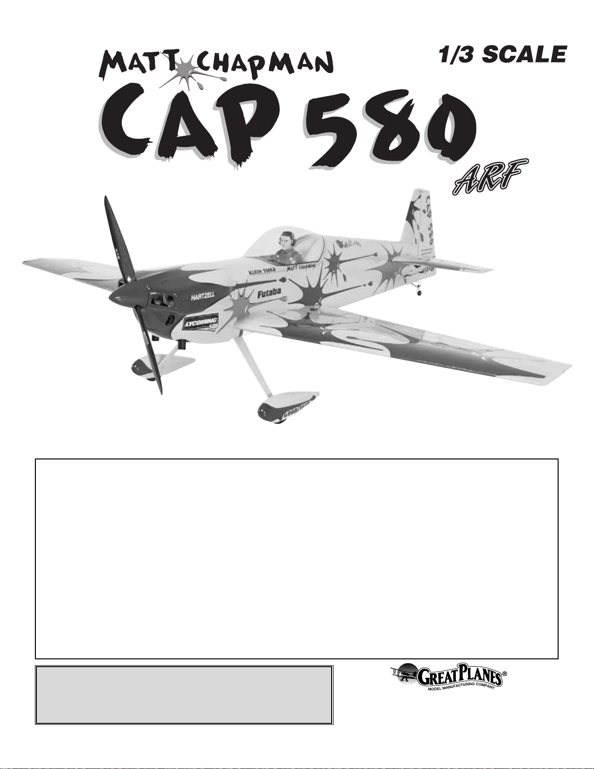
The Great Planes 1/3-scale Matt Chapman CAP 580 ARF
model is the latest in a long line of amazingly successful fullsized aerobatic aircraft, and this model follows the same
tradition of exceptional aerobatic models. Our CAP 580 is
carefully designed to model Matt Chapman’s impressive
competition plane. While aerobatic airplanes are NEVER
meant to be trainers, neither do they need to be difficult to fly.
In fact, a quality aerobatic airplane is, by definition, simple to
fly through basic maneuvers, making the pilot look good and
allowing the pilot to focus on the fine points and technicalities
of the maneuvers being performed. This model is designed
around this basic philosophy, and the resulting performance
is outstanding! The CAP 580 is no beginner’s airplane, so
you should be experienced with gasoline engines and at
least a 1.8 cu in [30cc] sized aircraft.This is mainly to ease
the transition to being able to judge the size, distance and
speed of a model this large. If you do not have experience
with gasoline engines, BE CERTAIN to get the assistance of
someone with that experience to test fly, trim, and assist you.
For the latest technical updates or manual corrections to the
Great Planes 1/3-scale Matt Chapman CAP 580 ARF visit
the Great Planes web site at
www.greatplanes.com
. Open
the “Airplanes” link, then select the Great Planes 1/3-scale
Matt Chapman CAP 580 ARF. If there is new technical
information or changes to this model a “tech notice” box will
appear in the upper left corner of the page.
We urge you to join the AMA (Academy of Model Aeronautics)
and a local R/C club.The AMA is the governing body of model
aviation and membership is required to fly at AMA clubs.
Though joining the AMA provides many benefits, one of the
primary reasons to join is liability protection. Coverage is not
limited to flying at contests or on the club field. It even applies
to flying at public demonstrations and air shows. Failure to
comply with the Safety Code (excerpts printed in the back of
the manual) may endanger insurance coverage. Additionally,
training programs and instructors are available at AMA club
sites to help you get started the right way. There are over
2,500 AMA chartered clubs across the countr y. Contact the
AMA at the address or toll-free phone number below:
Academy of Model Aeronautics
5151 East Memorial Drive
Muncie, IN 47302-9252
Tele.(800) 435-9262
Fax (765) 741-0057
Or via the Internet at:
http://www.modelaircraft.org
IMPORTANT!!! Two of the most important things you can do
to preserve the radio controlled aircraft hobby are to avoid
flying near full-scale aircraft and avoid flying near or over
groups of people.
AMA
INTRODUCTIONTABLE OF CONTENTS
2
Page 3

This aircraft is ideal for scale aerobatic competition. IMAC
events are popular in man y areas , and provide a g reat place
to discipline your flying skills, meet great people, and enjoy
your hobby all the more with like-minded pilots. Visit
www.mini-iac.com
for details.
If you would like photos of the full-size Great Planes 1/3scale Matt Chapman CAP 580, or if you would like to study
the photos to add more scale details, photo packs are
available from:
Bob’s Aircraft Documentation
3114 Y uk on Av e
Costa Mesa, CA 92626
Telephone:(714) 979-8058, Fax: (714) 979-7279
e-mail:
www.bobsairdoc.com
1.Your Great Planes 1/3-scale Matt Chapman CAP 580 ARF
should not be considered a toy, but rather a sophisticated,
working model that functions very much like a full-size
airplane. Because of its performance capabilities, the CAP
580, if not assembled and operated correctly, could possibly
cause injury to yourself or spectators and damage to property.
2. You must assemble the model according to the
instructions. Do not alter or modify the model, as doing so
may result in an unsafe or unflyable model. In a few cases
the instructions may differ slightly from the photos.In those
instances the written instructions should be considered
as correct.
3.You must take time to build straight, true and strong.
4. You must use an R/C radio system that is in first-class
condition, and a correctly sized engine and components
(fuel tank, wheels, etc.) throughout the building process.
5.You must correctly install all R/C and other components so
that the model operates correctly on the ground and in the air .
6.You must check the operation of the model before every
flight to insure that all equipment is operating and that the
model has remained structurally sound. Be sure to check
clevises or other connectors often and replace them if they
show any signs of wear or fatigue.
7. If you are not an experienced pilot or have not flown this
size and type of model before, we recommend that you get
the assistance of an experienced pilot in your R/C club for
your first flights. If you’re not a member of a club, your local
hobby shop has information about clubs in your area whose
membership includes experienced pilots.
8.While this kit has been flight tested to exceed normal use,
it is important
that the modeler understand that aerobatic
designs are not race planes, and should not be flown like
one. In addition, “more is better” is the WRONG philosophy
when powering an aerobatic plane. This model has been
professionally designed and tested, and the engine range
carefully selected for great performance. We strongly
recommend NOT exceeding the recommended engine
range. If the plane will be used for extremely high stress
flying outside the aerobatic envelope, such as r acing, or if an
engine larger than one in the recommended range is used,
the modeler is responsible for taking steps to reinforce the
high stress points and/or substituting hardware more
suitable for the increased stress. It is also important to note
that the warranty is void if the engine range is exceeded.
9. WARNING:The cowl and wheel pants included in this kit
are made of fiberglass, the fibers of which may cause eye,
skin and respiratory tract irritation. Never blow into a part
(wheel pant, cowl) to remove fiberglass dust, as the dust will
blow back into your eyes. Always wear safety goggles, a
particle mask and rubber gloves when grinding, drilling and
sanding fiberglass parts. Vacuum the parts and the work
area thoroughly after working with fiberglass parts.
Remember:Take y our time and f ollo w the instructions to
end up with a well-built model that is straight and true.
This is a partial list of items required to finish the Great
Planes 1/3-scale Matt Chapman CAP 580 that may require
planning or decision making before starting to build. Order
numbers are provided in parentheses.
❏ 6+ channel radio with:
❏ 1-2 standard ser vos (throttle and kill if applicable)
❏ 6 standard size high torque (90+oz/in) servos (2 for
elevator and 4 for ailerons)
❏ 2 giant scale size high torque (150+ oz/in) servos
(used for the rudder – see notes below)
Radio Equipment
DECISIONS YOU MUST MAKE
We, as the kit manuf acturer, provide y ou with a top quality,
thoroughly tested kit and instructions, but ultimately the
quality and flyability of your finished model depends on
how you build it; therefore, we cannot in any way
guarantee the performance of your completed model, and
no representations are expressed or implied as to the
performance or safety of your completed model.
PRO TECT YOUR MODEL,Y OURSELF
& OTHERS...FOLLOW THESE
IMPORTANT SAFETY PRECAUTIONS
IMAA
3
Page 4

❏ 2 6" [150mm] servo extensions (HCAM2701 for
Futaba) (outer aileron servos)
❏ 3 Y-harnesses (HCAM2751 for Futaba) (inner aileron
servos and rudder servos)
❏ 2 12" [300mm] servo extensions (HCAM2711 for
Futaba) (receiver to each wing)
❏ 1 24" [610mm] servo extension (HCAM2721 for
Futaba) (rudder servos)
❏ 1 36" [914mm] servo extension (HCAM2726 for
Futaba) (elevator servos)
❏ Receiver battery, 2000mAh minimum
RUDDER SERVO OPTIONS:
The large size of the rudder on the Giant CAP 580 requires
a lot of servo torque. Our testing shows that less than 300
inch ounces of servo power results in rudder “blow back”
during certain maneuvers.We have three recommendations
to provide adequate performance:
A.The instructions are written for two quarter scale Futaba
S5050 servos.This is the recommended setup.
B. It is possible to use standard size high torque servos
ganged together.There are two servo openings on either
side of the fuse for standard size servos. A 150+ oz/in
standard size servo can be installed on either side of the
fuse.T wo 2" [50mm] servo arms will need to be purchased.
C.Four standard size high torque servos (with a total of 300+
oz/in torque) can be used.This is the least recommended
of the setups, and will require modifications not covered in
this manual to install the 4 servos.
The recommended engine size range for the Great Planes 1/3scale Matt Chapman CAP 580 is 4.2-7.2 cu in [80-120cc].The
DA100 provided f antastic po wer with unlimited v ertical and the
weight balanced nicely. If an engine in the upper end of the
size range is used, remember that this is a scale model that is
intended to fly at scale-like speeds, so throttle management
must be practiced.
In addition to the items listed in the “Decisions You Must
Make” section, following is the list of hardware and accessories
required to finish the Great Planes 1/3-scale Matt Chapman
CAP 580. Order numbers are provided in parentheses.
❏ Suitable propeller
❏ R/C foam rubber 1/2" [13mm] - HCAQ1050
❏ 3' [900mm] gasoline fuel tubing (GPMQ4135)
❏ Engine kill switch (GPMG2150) (if using a gas engine)
In addition to common household tools and hobby tools, this
is the “short list”of the most important items required to build
the Great Planes 1/3-scale Matt Chapman CAP 580.
Great
Planes Pro™CA and Epoxy glue are recommended.
❏ 1 oz. [30g] Thin Pro CA (GPMR6002)
❏ 1 oz. [30g] Medium Pro CA+ (GPMR6008)
❏ Pro 30-minute epoxy (GPMR6047)
❏ Pro 6-minute epoxy (GPMR6045)
❏ Microballoons (TOPR1090)
❏ Drill bits: 1/16" [1.6mm], 5/64" [2mm], 3/32" [2.4mm], 7/64"
[2.8mm], 1/8" [3.2mm], 9/64" [3.6mm], 5/32" [4mm], 11/64"
[4.4mm], 3/16" [4.8mm], 13/64" [5.2mm], 7/32" [5.6mm],
15/64 [6mm], 1/4" [6.4mm], 17/64" [6.7mm], 9/32" [7.1mm]
❏ Tap handle (GPMR8120)
❏ Small metal file
❏ Velcro
®
hook & loop (1" x 6" [25 x 150mm], GPMQ4480)
❏ Stick-on segmented lead weights (GPMQ4485)
❏ #1 Hobby knife (HCAR0105)
❏ #11 blades (5-pack, HCAR0211)
❏ Single-edge razor blades (10-pack, HCAR0212)
❏ Medium T-pins (100, HCAR5150)
Here is a list of optional tools mentioned in the manual that
will help you build the Great Planes 1/3-scale Matt Chapman
CAP 580.
❏ 4 oz. [113g] aerosol CA activator (GPMR634)
❏ CA applicator tips (HCAR3780)
❏ CA debonder (GPMR6039)
❏ Epoxy brushes (6, GPMR8060)
❏ Mixing sticks (50, GPMR8055)
❏ Mixing cups (GPMR8056)
❏ Pliers with wire cutter (HCAR0630)
❏ Robar t Super Stand II (ROBP1402)
❏ Masking tape (TOPR8018)
❏ Milled fiberglass (GPMR6165)
❏ Threadlocker thread locking cement (GPMR6060)
❏ Denatured alcohol (for epoxy clean up)
❏ Rotar y tool such as Dremel
®
❏ Rotar y tool reinforced cut-off wheel (GPMR8200)
❏ Ser vo horn drill (HCAR0698)
❏ Laser incidence meter (GPMR4020)
❏ 36" bar for incidence meter (GPMR4021)
❏ Top Flite
®
MonoKote®sealing iron (TOPR2100)
❏ Top Flite MonoKote trim seal iron (TOPR2200)
❏ Top Flite MonoKote heat gun (TOPR2000)
Covering T ools
Optional Supplies and Tools
Adhesives and Building Supplies
Hardware and Accessories
ADDITIONAL ITEMS REQUIRED
Engine Recommendations
4
Page 5
• There are two types of screws used in this kit:
Sheet metal screws are designated by a number and a
length. For example #6 x 3/4" [19mm]
This is a number six screw that is 3/4
"
[19mm] long.
Machine screws are designated by a number, threads per
inch, and a length. For example 4-40 x 3/4" [19mm]
This is a number four screw that is 3/4"
[19mm] long with forty threads per inch
.
• When you see the term
test fit
in the instructions, it means
that you should first position the part on the assembly
without using any glue, then slightly modify or
custom fit
the part as necessar y for the best fit.
• Whenever the term
glue
is written you should rely upon
your experience to decide what type of glue to use.When
a specific type of adhesive works best for that step, the
instructions will make a recommendation.
• Whenever just
epoxy
is specified you may use
either
30minute (or 45-minute) epoxy or6-minute epoxy. When 30minute epoxy is specified it is highly recommended that
you use only 30-minute (or 45-minute) epo xy, because you
will need the working time and/or the additional strength.
• Photos and sketches are placed before the step they
refer to .Frequently you can study photos in following steps
to get another view of the same parts.
• The Great Planes 1/3-scale Matt Chapman CAP 580 ARF
is factory-covered with Top Flite MonoKote film. Should
repairs ever be required, MonoKote can be patched with
additional MonoKote purchased separately. MonoKote is
packaged in six-foot rolls, but some hobby shops also sell
it by the foot. If only a small piece of MonoKote is needed
for a minor patch, perhaps a fello w modeler would giv e y ou
some.MonoKote is applied with a model airplane covering
iron, but in an emergency a regular iron could be used. A
roll of MonoKote includes full instructions for application.
Following are the colors used on this model and order
numbers for six foot rolls.
Red TOPQ0201
Cub Yellow TOPQ0220
Orange TOPQ0202
Green TOPQ0214
Black TOPQ0208
Purple TOPQ0225
Blue TOPQ0206
Sapphire Blue TOPQ0227
White TOPQ0204
• The stabilizer and wing incidences and engine thrust
angles have been factory-built into this model. However,
some technically-minded modelers may wish to check
these measurements anyway.To view this information, visit
the web site at
www.greatplanes.com
and click on
“Technical Data.” Due to manufacturing tolerances that will
have little or no eff ect on the way your model will fly, please
expect slight deviations between your model and the
published values.
Fuse = Fuselage
Stab = Horizontal Stabilizer
Fin = Vertical Fin
LE = Leading Edge
TE = Trailing Edge
LG = Landing Gear
Ply = Plywood
" = Inches
mm = Millimeters
SHCS = Socket Head Cap Screw
COMMON ABBREVIATIONS
IMPORTANT BUILDING NOTES
5
Before starting to build, take an inventory of this kit to make sure it is complete and inspect the parts to make sure they
are of acceptable quality.If any parts are missing or are not of acceptable quality, or if y ou need assistance with assemb ly,
contact Product Support. When repor ting defective or missing parts, use the part names exactly as they are written in
the Kit Contents list.
Great Planes Product Support:
3002 N Apollo Drive, Suite 1
Champaign, IL 61822
Telephone: (217) 398-8970, ext. 5
Fax: (217) 398-7721
E-mail:
airsupport@greatplanes.com
KIT INSPECTION
Page 6
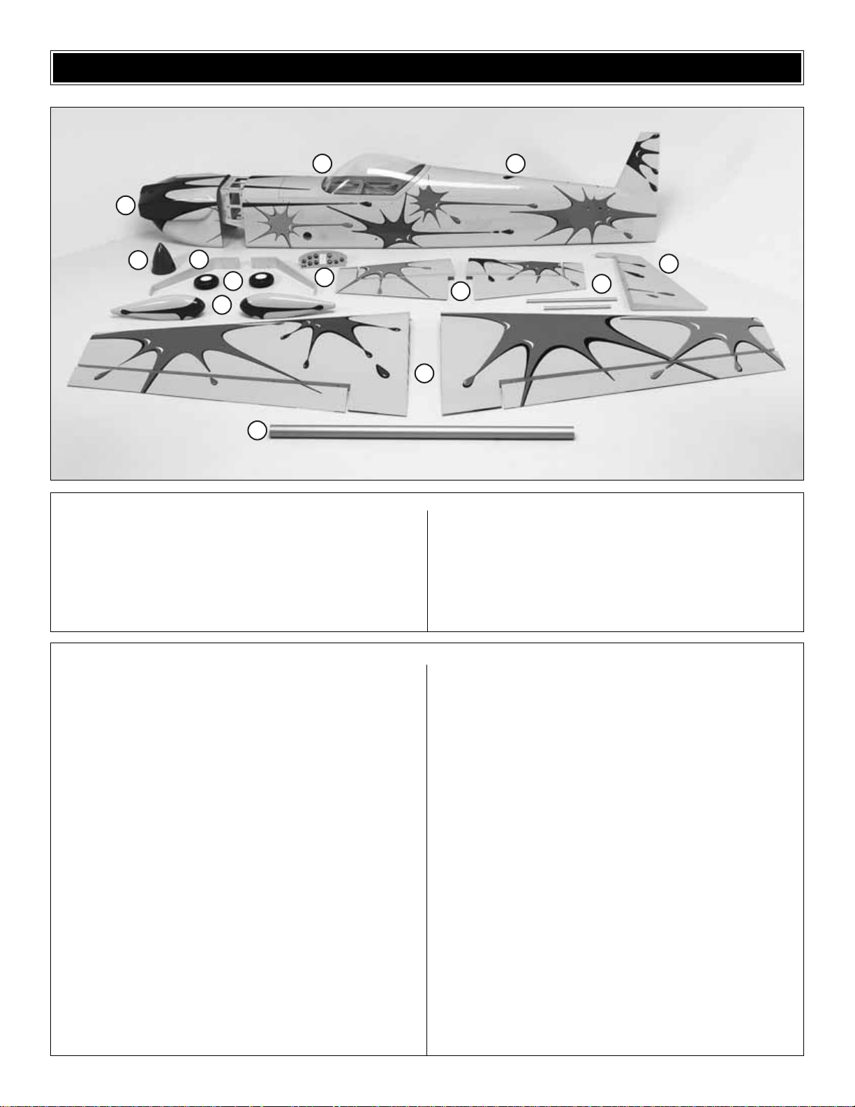
6
1 Cowl
2 Fuselage
3 Canopy/Hatch
4 Aluminum Spinner
5 Main Gear
6 Wheels
7 Wheel Pants
8 Instr ument Panel
9 Stab and Elevators
10 Stab T ubes
11 Rudder
12 Wings and Ailerons
13 Wing T ube
Kit Contents (Photographed)
Brass Quick Connect Body (2)
4-40 Threaded Steel Cevis (4)
Axles (2)
4-40 Blind Nut (8)
8-32 Blind Nut (18)
Nuts for Axles (2)
1/4-20 Blind Nuts (6)
4-40 Lock Nut (8)
Nylon Clevis (1)
Nylon Retainer (2)
36" Flexible Pushrod Tube (2)
36" Inner Flexible Pushrod Tube (2)
Retainers (5)
6/32 x 1/4" Socket Head Cap Screws (4)
#4 x 5/8" Wood Screw (8)
4-40 Set Screw (2)
8-32 x 3/4" Socket Head Cap Screws (18)
4-40 x 1/2" Socket Head Cap Screws (8)
4-40 x 3/4" Socket Head Cap Screws (2)
1/4" Flat Washers (4)
3/16" Wheel Collars (4)
2-56 x 4" Wire Threaded One End (4)
4-40 x 12" Fully Threaded Rod (1)
#4 Lock Washer (14)
#4 Flat Washer (14)
#8 Lock Washer (18)
#8 Flat Washer (18)
1-1/2" Tailwheel (1)
1/4" x 2-1/2" Hex Bolt (4)
1/4" Lock Washer (4)
Antirotation Dowels for the Wing (4)
Engine Spacers, 6mm Thick, Aluminum (20)
Fuel Tank (1)
Pilot (1)
Pin Hinges (33)
Servo Tra y (1)
Stab Tube Aft (1)
Stab Tube Front (1)
Decal Sheet (2)
Tail Gear Assembly (1)
Ball Link Set (8)
Control Horn Set (8)
Pushrods 2-1/2" (6)
Pushrods 4-1/2" (2)
Servo Arm Set (1)
Kit Contents (Not Photographed)
KIT CONTENTS
1
4
3
5
6
7
13
8
9
12
2
11
10
Page 7

7
ORDERING REPLACEMENT PARTS
Replacement parts for the Great Planes 1/3-scale Matt Chapman CAP 580 ARF are available using the order numbers in
the Replacement Parts List that follows.The fastest, most economical service can be provided by your hobby dealer or
mail-order company.
To locate a hobby dealer, visit the Great Planes web site at
www.greatplanes.com
. Choose “Where to Buy” from the menu
on the left side of the page. Follow the instructions provided on the page to locate a U.S., Canadian or International dealer. If
a hobby shop is not av ailab le , replacement parts may also be ordered from Tower Hobbies at
www.towerhobbies.com
, or by
calling toll free (800) 637-6050.
Parts may also be ordered directly from Hobby Services by calling (217) 398-0007, or via facsimile at (217) 398-7721, but
full retail prices and shipping and handling charges will apply. Illinois and Nevada residents will also be charged sales tax.
If ordering via fax, include a Visa®or MasterCard®number and expiration date for payment.
Mail parts orders and payments by personal check to:
Hobby Services
3002 N Apollo Drive, Suite 1
Champaign IL 61822
Be certain to specify the order number exactly as listed in the Replacement Parts List.Payment by credit card or personal
check only; no C.O.D.
If additional assistance is required for any reason contact Product Support by e-mail at
productsupport@greatplanes.com
,
or by telephone at (217) 398-8970.
Replacement Parts List
Or
der Number Description How to Purchase
Missing pieces ................................................Contact Product Support
Instruction manual...........................................Contact Product Support
Full-size plans.................................................Not available
Kit parts listed below .......................................Hobby Supplier
GPMA2650............Wing Set
GPMA2651............Fuselage
GPMA2652............Stabilizer/Elevator Set
GPMA2653............Stabilizer Joiner Tubes
GPMA2654............Rudder
GPMA2655............Wing Joiner Tube
GPMA2656............Cowl
GPMA2657............Hatch/Canopy
GPMA2658............Landing Gear
GPMA2659............Wheel Pants
GPMA2660............Spinner
GPMA2661............Instrument Panel
GPMA2662............Tailwheel Assembly (without wheel)
GPMA2663............Decal Set
Page 8
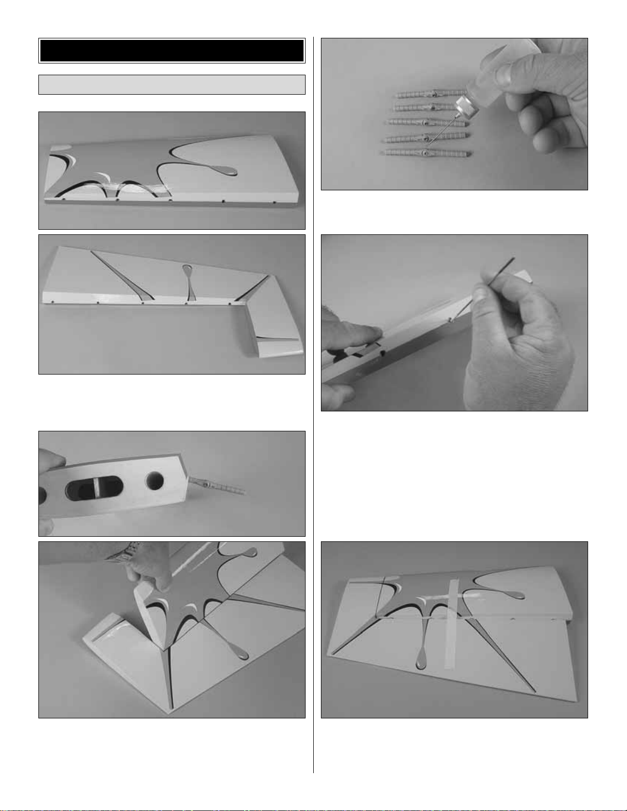
❏❏1. Cut the covering from the five holes for the hinge
points in the trailing edge of one of the stab halves and the
leading edge of the elevator.
❏❏2.Temporarily attach the elevator to the stab with five
hinges. Note the inner hinges go in at an angle to clear the
stab tube.Check that there is free movement of the elevator
through all of its throw. Remove the hinges.
❏❏3. Place a drop of oil on the pivot point of each of
the hinges.
❏❏4. Mix up some 30-minute epoxy and microballoons
(if using mixing cups, approximately 1/4 oz.of microballoons
added to 1/8 oz. of mixed epoxy is recommended). Use a
piece of music wire to thoroughly apply the mixture in the
holes in the stab and elevator.Use the wire to get the epoxy
out of the outer edge of the opening of the holes in the
elevator so it doesn’t get into the hinge pins.Wipe away any
epoxy around the outside of the holes with a paper towel.
❏❏5.Fit the hinges in the stab and elevator .Tape the stab
to the elevator and set aside until the epoxy has cured.
❏ 6. Repeat steps 1 through 5 for the other stab half.
Attach the Elevators
ASSEMBLE THE ST AB
8
Page 9
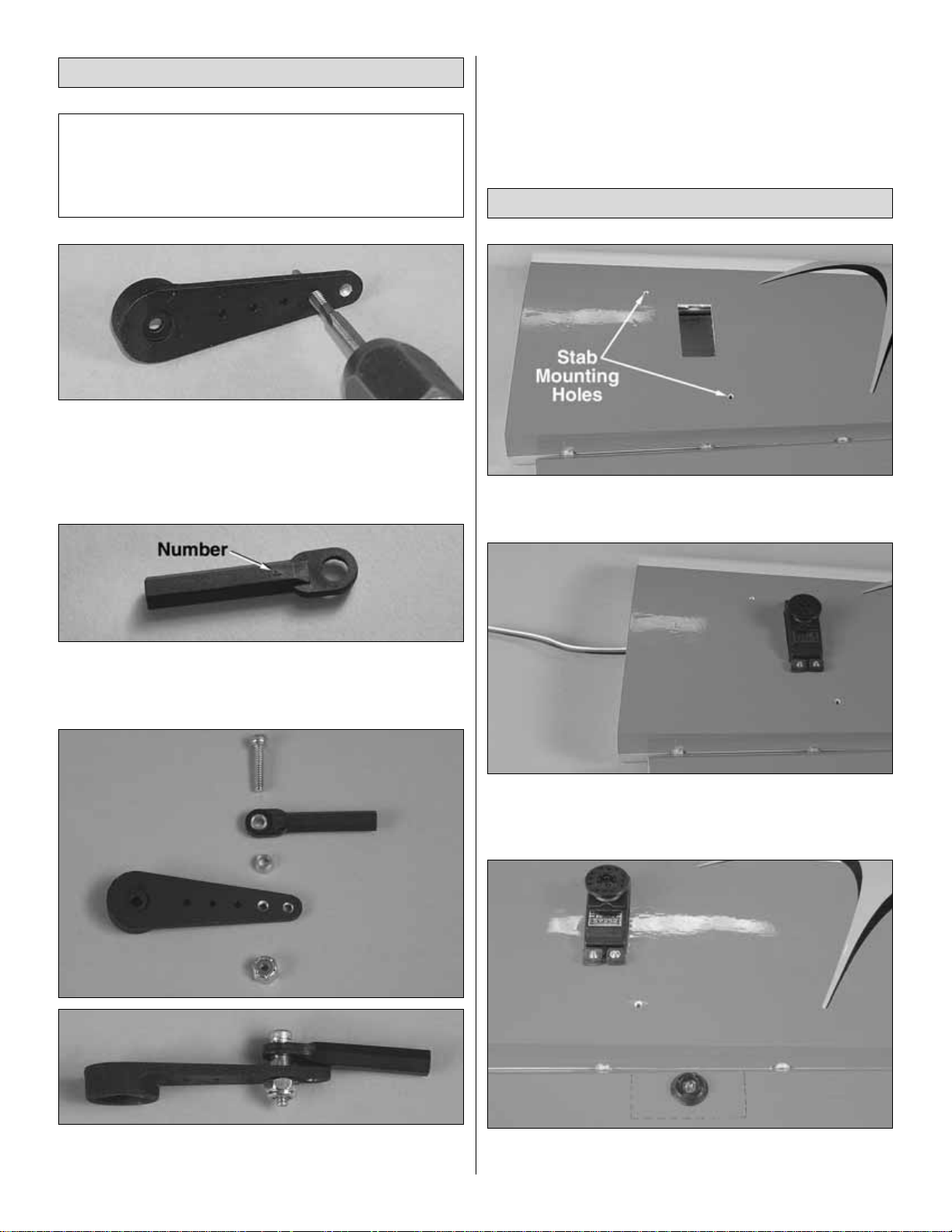
❏ 1. Drill and tap 4-40 threads in the two outermost holes
of each of the six single-sided servo arms.
❏ 2.Drill and tap 4-40 threads in the outer hole of the 4-1/4"
[106mm] servo arm.
❏ 3.The nylon ball links have a number on one side of them.
With the number facing up, press the brass ball into each of
the nylon balls link from the bottom, opposite the number.
❏ 4. Attach the ball link to the inner tapped hole of one of
the one-sided servo arms with 4-40 x 1/2" [13mm] Socket
Head Cap Screw [SHCS] brass stand off and 4-40 lock nut.
Note: The number goes toward the servo arm.
❏ 5. Attach the ball links to the five other single-sided
servo arms.
❏❏1.Trim the covering from the servo opening and stab
mounting holes in the bottom of one stab.
❏❏2.Mount the elevator servo to that stab half, using the
hardware provided with your servos, remembering to harden
the threads with thin CA.
❏❏3. Center the nylon pivot washer on the plywood
support and align it with the leading edge of the elevator.
Mount the Elevator Servos
Note:The included aluminum servo arms are designed with
plastic inserts, allowing the arms to work with all current
Futaba, Hitec, Airtronics and JR servos.The inserts are also
designed so that the centering of the arm can be adjusted
by rotating the insert and then re-attaching the arm.
Prepare the Servo Arms
9
Page 10

❏❏4. Drill a 9/64" [3.6 mm] hole through the elevator
centered on the pivot washer.
❏❏5. Cut the 4" [100mm] control horn bolt to a length of
2-1/4" [57mm].
❏❏6.Place a pivot washer on the control horn bolt.Screw
the control horn bolt through the top of the elevator.
❏❏7. Screw the nylon nut and pivot washer onto the
control horn bolt.
❏❏8. Assemble the control horn parts as shown.
❏❏9. Screw the rever se threaded end of the 2-1/2"
[65mm] pushrod 15 full turns into the control horn. (To tighten,
turn counterclockwise.)
❏❏10. Screw the “normal” threaded end of the pushrod
15 turns into the ball link that is connected to one of the
single-sided servo arms.
❏❏11. Screw the control horn onto the control hor n bolt,
leaving 1/16" [1.6mm] extending from the top of the control horn.
10
Page 11

❏❏12. Remove the stock servo arm from the servo.Plug
the servo into the receiver and turn the radio on.
❏❏13. Place the appropriate servo arm insert on the
servo. The inserts have letters stamped on the bottom of
them (A=Airtronics/JR, F=Futaba, H=Hitec).
❏❏14. Attach the aluminum servo arm to the servo so
that it is 90 degrees to the long side of the servo case.If it is
not, remove the servo arm, rotate the insert 90 degrees and
attach the servo arm again. Use the insert position that
makes the servo arm fit closest to 90 degrees. Be sure to
secure the servo arm with the screw.
❏❏15. Adjust the pushrod by turning it until the elevator
is centered on the stab.
❏ 16. Repeat steps 1-15 for the other stab half.
❏❏1. Repeat the hinging process used on the stab to
attach one aileron to its wing.
❏❏2. Remove the covering from the servo openings in
the bottom of the wing.
❏❏3. Secure one aileron servo lead to a long Y-har ness
with string or a piece of heat shrink tubing (not included).
Hobbico Heavy Duty Y-Harnesses (HCAM2751) were used
on our models.
❏❏4. Use the string in the wing to pull the y-harness
through the wing from the outer servo opening. Pull the
second end of the y-harness out of the inner servo opening.
Secure the second servo lead to the Y-harness just as you
did with the first one.Mount the servos, noting that the servo
arms go toward the trailing edge of the wing.
ASSEMBLE THE WING
11
Page 12

❏❏5. Mount the control horns and ser vo arms following
the same steps used with the stab.
❏❏6. Glue the white nylon anti-rotation dowels in the
wing with epoxy.
❏ 7. Repeat steps 1-6 for the other wing.
❏ 1. Grind flat spots on the tail gear wire for the set screws.
Assemble the tail gear as shown in the photo with threadlock er .
❏ 2. Remove the covering for the tail gear mounting bolts.
Attach the tail gear with threadlocker, 4-40 x 3/4" [19mm]
SHCS, #4 flat washer and #4 lock washer.
❏ 3. Attach the tail gear steering arm to the bottom of the
rudder with two #4 x 5/8" wood screws.
Install the Tail Gear
ASSEMBLE THE FUSE
12
Page 13

❏ 1. Mark the r udder 2-1/4" [57mm] from the bottom and
3/8" [9.5mm] from the LE. Drill a 9/64" [3.6mm] hole through
the rudder.Be certain to drill perpendicular to the centerline
of the rudder.
❏ 2. Mount the rudder control hor ns as shown, using the
remaining uncut 4" bolt.
❏ 3. Hinge the rudder using the same procedure used on
the stabs and wings. Note: don’t forget to oil the pivot point
of each hinge.
❏4.Attach the tail gear arm to the tail gear with the two springs.
❏ 1. Install the two giant-scale ser vos with the hardware
provided with the servos.(We used Futaba S5050 servos in
our models.)
❏ 2. Remove the covering from the pushrod exits on both
sides of the fuse.
RUDDER SER VO OPTIONS:
The large size of the rudder
on the Giant CAP 580 requires a lot of servo torque. Our
testing shows that less than 300 ounce inches of servo
power results in rudder “blow back” during certain
maneuvers. We have three recommendations to provide
adequate performance:
A. The instructions are written for two quarter-scale
Futaba S5050 servos.This is the recommended setup.
B. It is possible to use standard size high-torque servos
ganged together. There are two servo openings on
either side of the fuse for standard size servos.A 150+
oz/in standard size servo can be installed on either
side of the fuse.T wo 2" [50mm] servo arms will need to
be purchased.
C. Four standard size high torque servos (with a total of 300+
oz/in torque) can be used.This is the least recommended
of the setups, and will require the modeler to modify the
model to install the 4 servos.
Install the Rudder Servo(s)Attach the Rudder
13
Page 14

❏ 3. Install the rudder linkage and servo arm as shown.
❏ 4. Fit the included 2-1/4" [57mm] double-sided servo arm
on the forward rudder servo.
❏ 5. Cut two 2" [50mm] pieces from the 4-40 x 12" [305mm]
threaded rod.
❏ 6.Solder a 4-40 metal clevis to one end of each of the 2"
threaded rods.
❏7.Install the 2" double-sided servo arm on the forward servo .
❏ 8. Install the pushrods. Note: If any binding occurs,
slightly enlarge the holes in the servo arms. A small amount
of free play is preferred with these 2 pushrods to avoid the 2
servos “fighting” one another.
❏❏1.Attach the axle to the main gear with the nylon lock nut.
❏❏2. Install a wheel collar with a 6-32 x 1/4" [6mm]
SHCS, the wheel and the other wheel collar also with a
6-32 x 1/4" [6mm] SHCS.
❏ 3. Mount the wheel pant with two 8-32 x 3/4" [19mm]
SHCS. Center the wheel in the wheel pant and tighten the
wheel collars.
❏❏4. Remove the wheel pant. Mark the location of the
wheel collars.File flat spots on the axles for SHCS that hold
the wheel collars in place.
❏❏5. Mount the wheel with the wheel collars. Mount the
wheel pant using threadlocker, two 8-32 x 3/4" [19mm]
SHCS, two #8 flat washers and two #8 lock washers.
Install the Main Gear
14
Page 15

❏❏6.Mount the landing gear to the fuse with threadlocker ,
four 8-32 x 3/4" [19mm] SHCS, four #8 flat washers and four
#8 lock washers.
❏ 7.Repeat steps 1 through 6 for the other landing gear leg.
❏ 1. If you are using a DA100, cut the engine mounting
template from the rear of this manual.Align the printed lines
with the lines on the firewall and tape the sketch in place. If
you are using a different engine, use the template provided
by the engine’s manufacturer to center the engine on the
embossed lines on the firewall.
❏ 2. Drill 5/16" [8 mm] holes through the firewall at the
locations indicated by the template.
❏ 3. Mount the engine to the firewall with 1/4-20 x 2-1/2"
[64mm] bolts and the correct number of aluminum spacers
required to make the total distance from firewall to the thrust
washer at least 7-1/2" [190mm].
❏ 4.After reading the caution provided immediately following
this step, and remembering the importance of maintaining at
least 12" [300mm] between anything engine/ignition related
and anything radio related, follow the engine manufacturer’s
instructions to mount the ignition module. On our airplanes,
we mounted it inside the top of the firewall box.
Because of the possibility of ignition engines creating
radio noise, we use a plastic pushrod for the throttle
servo installation.This isolates the engine and any radio
noise from the servos.This is an IMPORTANT selection,
and we cannot recommend strongly enough that you
DO NOT change this pushrod to a metal pushrod. All
radio equipment – including throttle servo, receiver
battery, electronic kill switch, receiver on/off switch,
servo leads – should be mounted at least 12" [300mm]
away from anything related to the ignition/gasoline
engine. Any material used between the engine and the
radio equipment is STRONGLY recommended to be
plastic, nylon, or otherwise non-metallic and nonconductive to minimize ignition noise transmission.
Install the Throttle Servo
Mount the Engine
15
Page 16

❏ 1. Drill a 3/16" [4.8mm] hole through the firewall and
second former aligned with the throttle arm on engine.
❏ 2. Glue a grey 3/16" x 36" [4.8 x 914mm] plastic pushrod
tube to the holes in the firewall and second former,
leaving approximately 1" [25mm] protruding from the front of
the firewall.
❏ 3. Cut the end of the pushrod tube even with the front of
the servo tray.
❏ 4. Mount your throttle servo in the tray.
❏ 5. Cut a 1" [25mm] threaded section from one of the
2-56 x 4" [102mm] pushrods. Attach the nylon clevis to the
white plastic pushrod using the threaded section.
❏ 6. Slide the white plastic pushrod through the pushrod
tube and attach the clevis to the throttle arm. Cut the other
end flush with the servo end of the grey pushrod tube.Screw
a 2-56 x 4" [102mm] pushrod into the white pushrod tube.
16
Page 17

❏ 7. Slide three plywood pushrod supports over the grey
pushrod tube.Attach the pushrod to the servo with the brass
screw lock connector. Glue the supports to the formers and
the pushrod tube.
❏ 1.Drill a 7/64" [2.8mm] hole through the end of the metal
tab on the kill switch.
❏ 2. Drill a 3/16" [4.8mm] hole through the second former
roughly in the location shown.
❏ 3. Install the grey pushrod outer tube in the fuse the
same as was done with the throttle servo.
❏ 4.Screw a 2-56 x 4" [102mm] pushrod 10 turns into the
white pushrod tube.
❏ 5. Attach the pushrod to the kill switch with two 3/32"
[2.4mm] wheel collars and two 1/2" [13mm] pieces of fuel line.
❏ 6. Mount the kill switch to the side of the firewall box with
two #4 x 5/8" [16mm] screws so that the pushrod lines up
with the hole in the kill switch.
❏ 7. Mount the kill switch servo .Connect the pushrod to the
servo the same way the throttle servo was done.
❏ 8. Wire the servo operated kill switch and manually
operated kill switch for your ignition.
For safety,Great Planes recommends the installation of
both a servo operated kill switch and a manual kill
switch. A Great Planes kill switch (GPMG2150, not
included) is used in all of our gasoline-powered aircraft.
Install the Recommended Servo-Operated
Kill Switch (Not Included)
17
Page 18

❏ 1. Assemble the stopper, brass tubes and steel stopper
end plates as shown.
❏ 2. Solder the brass barbs to the ends of the brass tubes.
Note: Get the tubes just hot enough for the solder to flow.If
you get the tubes too hot it will damage the tank stopper.
❏ 3. Attach the clunks to the short brass tubes with 5"
[127mm] pieces of fuel line.
❏ 4. Install the stopper assembly in the tank with the vent
line toward one of the longer sides of the tank. Mark that
side of the tank as top.
❏5.Mount the tank to the tank tray with two #64 rubber bands.
❏ 6. Mount the tank tray to the fuse with four #4 x 5/8"
[15.9mm] screws and #4 flat washers.
❏ 7. Install the fuel lines. One clunk line goes to the
carburetor; the other clunk line is for filling; the vent line gets
routed out the bottom of the fuse.
❏ 1. Slide the cowl over the engine onto the fuselage.Use a
Dremel tool with a cutting bit to trim the cowl where necessary
Mount the Cowl
Assemble and Install the Fuel Tank
18
Page 19

so you can get it to fit over the engine. If you are using the
DA100, only a small hole for the front of the left muffler and
slots for the muffler tubes need to be cut.
❏ 2. Cut a rectangle out of the bottom of the cowl that
matches the air exit slot in the fuse.
❏ 3. Mount the spinner and position the cowl 1/8" [3.2mm]
behind the spinner backplate.
❏ 4. Drill a 9/64" [3.6mm] hole 3/4" [19mm] forward of the
T.E.of the cowl and just below the cheek.
❏ 5. Attach the cowl at that point with a 4-40 x 1/2" [13mm]
SHCS, #4 washer and 4-40 blind nut.
❏ 6.Working one at a time, repeat steps 4 and 5 to install
3 bolts on each side of the cowl.
❏ 1. Slide the two aluminum stab tubes into the fuse.
❏ 2. Attach 36" [915mm] servo extensions to the elevator
servos. If you are going to be permanently attaching the
stabs, secure the servo leads with heat shrink tubing.
❏ 3. Stand the plane on its nose and feed the elevator
servo wire down the fuse.
The removable tail needs to be checked often for wear.
If the tail develops excessive movement, thin CA
sparingly applied to the inside of the stab tubes will
cure it. If you are able to transport the CAP with the
stabs installed, we recommend permanently attaching
the stab to the fuse with epoxy.
Mount the Stabilizers
FINAL ASSEMBLY
19
Page 20

❏ 4. Slide the stabs onto the aluminum tubes witht he stab
root ribs tight on the fuse side.
❏ 5. Drill a 1/16" [1.6mm] hole through the forward and aft
stab tubes, using the holes in the bottom of the stab half as
a guide. Be careful not to dr ill through the stab.
❏ 6. Attach the stab half to the tubes with two #4 x 5/8"
[15.9mm] screws and two #4 washers.
❏ 7. Have an assistant hold the stab halves tight against
the fuse. Dr ill the tubes for the second stab half.
❏ 8. Attach the second stab half to the tubes with two #4 x
5/8" screws and two #4 washers.
❏ 9. Attach 36" [915mm] servo extensions to the rudder
servos. Route the extensions to the radio compar tment.
❏ 10. Install the rudder servo hatch with two #4 x 5/8"
[16mm] screws.
❏ 1. Wrap your receiver and battery in 1/2" [13mm] foam.
Mount your receiver and battery to the servo tray with the
Velcro strips.
❏ 2. Plug in all of the servos, including the two 6" [150mm]
extensions for the ailerons.
❏ 3. Mount the switch and charge jack.
There are two wing locations on the plane. The reason
for this is so that a range of engines can be used without
the need for adding large amounts of weight to balance.
❏ 1. First, determine which wing mounting location you will
use. To do so, mount everything in the plane except the
canopy and wing.Reach under the tank and lift the plane by
the aft wing tube. If the plane is balanced, tail-heavy, or just
slightly nose-heavy at this location, then this is where the
wing will be mounted.If the plane is significantly nose-heavy,
set it down and lift it by the forward wing tube.If the plane is
more closely balanced, or still nose-heavy, using the f orward
tube, then this will be your wing location.If the plane is now
tail-heavy using the forward wing tube to lift, use some
weight strips to balance the plane in each location. Mount
the wing in the position which requires the least weight.
❏ 2. Cut the covering from the wing tube locations you
selected in step 1.
❏ 3. Slide the wing tube through the fuse.
❏ 1. Slide one wing onto the wing tube. Remove the
covering from the appropriate holes in the fuselage for the
wing dowels.
❏ 2. Attach the wing to the fuselage with the 1/4"20 x 2"
[50mm] nylon bolt.
❏ 3. Attach the second wing to the fuselage.
Mount the Wing
Check the C.G.
Finish the Radio Installation
20
Page 21

❏ 1. Attach the pilot to the canopy frame with 6-minute epoxy.
❏ 2. Attach the instrument panel to the canopy frame with
medium CA.
❏ 3. Remove the covering from the six mounting holes for
the canopy/hatch.
❏ 4. Mount the canopy to the fuselage with six 8/32 x 1"
[25.4mm] SHCS, flat washers and lock washers.
1.Use scissors or a sharp hobby knife to cut the decals from
the sheet.
2. Be certain the model is clean and free from oily
fingerprints and dust. Prepare a dishpan or small bucket with
a mixture of liquid dish soap and warm water—about one
teaspoon of soap per gallon of water.Submerse the decal in
the soap and water and peel off the paper backing. Note:
Even though the decals hav e a “sticky-back”and are not the
water transfer type , submersing them in soap & water allo ws
accurate positioning and reduces air bubbles underneath.
3. Position decal on the model where desired, using the
picture on the box as a guide.Holding the decal down, use a
paper towel to wipe most of the water away.
4.Use a piece of soft balsa or something similar to squeegee
remaining water from under the decal. Apply the rest of the
decals the same way.
❏ 1.T urn on the transmitter and receiver and center the trims.
If necessary, remove the servo arms from the servos and
reposition them so they are centered.Reinstall the screws that
hold on the servo arms.
❏ 2. With the transmitter and receiver still on, check all the
control surfaces to see if they are centered.If necessary, adjust
the clevises on the pushrods to center the control surfaces.
❏ 3. Make certain that the control surfaces and the
carburetor respond in the correct direction as shown in the
diagram.If any of the controls respond in the wrong direction,
use the servo reversing in the transmitter to reverse the
servos connected to those controls. Be cer tain the control
surfaces have remained centered. Adjust if necessary.
Check the Control Directions
GET THE MODEL READY TO FLY
Apply the DecalsAttach the Canopy
21
4-CHANNEL RADIO SETUP
(STANDARD MODE 2)
4-CHANNEL
TRANSMITTER
ELEVATOR MOVES UP
RUDDER MOVES RIGHT
4-CHANNEL
TRANSMITTER
4-CHANNEL
TRANSMITTER
RIGHT AILERON MOVES UP
LEFT AILERON MOVES DOWN
CARBURETOR WIDE OPEN
4-CHANNEL
TRANSMITTER
Page 22

Use a Great Planes AccuThrow™(or a ruler) to accurately
measure and set the control throw of each control surface
as indicated in the chart that follows. NOTE: The throws
are measured at the widest part of the elevators, rudder
and ailerons.
At this stage the model should be in ready-to-fly condition
with all of the systems in place including the engine, landing
gear, and the radio system.
NOTE: For a model this large, checking the CG requires
two people.
❏ 1. Using a felt-tip pen or 1/8" [3mm]-wide tape, accurately
mark the C.G. on the tips of both wing panels. The C.G. is
located 3-1/2" [90mm] back from the leading edge of the
wing A T THE WINGTIP , NOT THE FUSELAGE!
❏ 2.With the wing attached to the fuselage, all parts of the
model installed (ready to fly) and an empty fuel tank, you
and your helper lift the model from the marked CG location.
❏ 3. If the tail drops, the model is “tail heavy”and the battery
pack and/or receiver must be shifted forward or weight must
be added to the nose to balance.If the nose drops, the model
is “nose heavy”and the battery pack and/or receiver must be
shifted aft or weight must be added to the tail to balance.
This is where your model should balance for the first
flights. Later, you may wish to experiment by shifting the
C.G. up to 1/2" [13mm] forward or 1/2" [13mm] back to
change the flying characteristics. Moving the C.G. forward
may improve the smoothness and stability, but the model
may then require more speed for tak eoff and mak e it more
difficult to slow for landing.Moving the C.G.aft makes the
model more maneuverable, but could also cause it to
become too difficult to control. In any case, start at the
recommended balance point and do not at any time
balance the model outside the specified range.
More than any other factor, the C.G. (balance point) can
have the greatest effect on how a model flies, and may
determine whether or not your first flight will be
successful. If you value this model and wish to enjoy it for
many flights, DO NOT OVERLOOK THIS IMPORTANT
PROCEDURE. A model that is not proper ly balanced will
be unstable and possibly unflyable.
Balance the Model (C.G.)
IMPORTANT: The Great Planes 1/3-scale Matt Chapman
CAP 580 ARF has been professionally and extensively
flown and tested to arrive at the throws at which it flies best.
Flying your model at these throws will provide you with the
greatest chance for successful first flights.If, after you have
become accustomed to the way the Great Planes 1/3-scale
Matt Chapman CAP 580 ARF flies, you would like to
change the throws to suit your taste, that is fine.However,
too much control throw could make the model difficult to
control, so remember, “more is not always better.”
These are the recommended control surface throws:
High Rate Low Rate
ELEVATOR: 1-1/8" [28mm] up 7/8" [22mm] up
1-1/8" [28mm] down 7/8" [22mm] down
RUDDER: 3" [76mm] right 2" [50mm] right
3" [76mm] left 2" [50mm] left
AILERONS: 1-3/4" [44mm] up 1-3/8" [35mm] up
1-3/4" [44mm] down 1-3/8" [35mm] down
For all out 3D: Set the throws
as high as possible without binding.
Set the Control Throws
22
Page 23

23
❏ 4. If possible, relocate the battery pack and receiver to
minimize or eliminate any additional ballast required. If
additional weight is required, nose weight may be easily
added by using Great Planes (GPMQ4485) “stick-on” lead. A
good place to add stick-on nose weight is to the firewall or the
engine box itself (don’t attach weight to the cowl—it is not
intended to support weight). Begin by placing incrementally
increasing amounts of weight on the engine box behind the
engine until the model balances. Once you have determined
the amount of weight required, it can be permanently
attached.If required, tail weight may be added by temporarily
removing the rudder servo hatch, installing the lead inside
well clear of the servos, and reinstalling the hatch.
Note: Do not rely upon the adhesive on the back of the lead
weight to permanently hold it in place. Over time, fuel and
exhaust residue may soften the adhesive and cause the
weight to fall off .Use #2 sheet metal screws, RTV silicone or
epoxy to permanently hold the weight in place.
❏ 5. IMPORTANT: If you found it necessary to add any
weight, recheck the C.G.after the weight has been installed.
NOTE: Lateral balance is far more important to a precision
aerobatic model than to the typical trainer, sport, or scale
aircraft. As such, checking lateral balance is handled far
more precisely for this type of aircraft.This process requires
the assistance of 2 or ideally 3 people.
❏ 1. With the wing level, have an assistant help you lift the
model by the engine propeller shaft and the bottom of the
fuse via the tail gear.
❏ 2. Have your second assistant measure the distance
each tip is above the floor.
❏ 3. Repeat the lift 3 or 4 times, checking the distance each
time, and averaging the distances.
❏ 4. If one wing is more than 1/4" lower than the other on
average, that side is heavy. Balance the air plane by adding
weight to the other wing tip until it balances to within 1/4".
No matter if you fly at an AMA sanctioned R/C club site or if
you fly somewhere on your own, you should always have
your name, address, telephone number and AMA number
on or inside your model. It is required at all AMA R/C club
flying sites and AMA sanctioned flying events.
Follow the battery charging instructions that came with your
radio control system to charge the batteries. You should
always charge your transmitter and receiver batteries the
night before you go flying, and at other times as
recommended by the radio manufacturer.
Carefully balance your propeller and spare propellers before
you fly.An unbalanced prop can be the single most significant
cause of vibration that can damage your model. Not only will
engine mounting screws and bolts loosen, possibly with
disastrous effect, but vibration may also damage your radio
receiver and battery. Vibration can also cause your fuel to
foam, which will, in turn, cause your engine to run hot or quit.
If the engine is new, follow the engine manufacturer’s
instructions to break-in the engine. After break-in, confirm
that the engine idles reliably, transitions smoothly and r apidly to
full power and maintains full power—indefinitely. After you run
the engine on the model, inspect the model closely to make
sure all screws remained tight, the hinges are secure, the prop
is secure and all pushrods and connectors are secure.
Ground check the operational range of your r adio before the first
flight of the day. With the transmitter antenna collapsed and the
receiver and transmitter on, you should be able to walk at least
100 feet away from the model and still have control. Have an
assistant stand by your model and, while you w ork the controls,
tell you what the control surfaces are doing.Repeat this test with
the engine running at various speeds with an assistant holding
the model, using hand signals to show you what is happening.If
the control surfaces do not respond correctly, do not fly! Find
and correct the problem first. Look for loose servo connections
or broken wires, corroded wires on old servo connectors, poor
solder joints in your battery pack or a defective cell, or a
damaged receiver crystal from a previous crash.
Range Check
Ground Check
Balance Propellers
CAUTION: Unless the instructions that came with your
radio system state differently, the initial charge on new
transmitter and receiver batteries should be done for 15
hours using the slow-charger that came with the radio
system.This will “condition” the batteries so that the next
charge may be done using the fast-charger of y our choice.
If the initial charge is done with a fast-charger the
batteries may not reach their full capacity and you may be
flying with batteries that are only partially charged.
Charge the Batteries
Identify Y our Model
PREFLIGHT
Balance the Model Laterally
Page 24

• Keep all engine fuel in a safe place, away from high heat,
sparks or flames, as fuel is very flammable. Do not smoke
near the engine or fuel; and remember that engine exhaust
gives off a great deal of deadly carbon monoxide .Therefore
do not run the engine in a closed room or garage.
• Get help from an experienced pilot when learning to
operate engines.
• Use safety glasses when starting or r unning engines.
• Do not r un the engine in an area of loose gravel or sand;
the propeller may throw such material in your face or eyes.
• Keep your face and body as well as all spectators away
from the plane of rotation of the propeller as you start and
run the engine.
• Keep these items away from the prop:loose clothing, shir t
sleeves, ties, scarfs, long hair or loose objects such as
pencils or screwdrivers that may fall out of shirt or jacket
pockets into the prop.
• Use a “chicken stick” or electr ic star ter to start the engine.
Do not use your fingers to flip the propeller. Make cer tain
the glow plug clip or connector is secure so that it will not
pop off or otherwise get into the running propeller.
• Make all engine adjustments from behind the rotating prop.
• The engine gets hot! Do not touch it during or right after
operation. Make sure fuel lines are in good condition so
fuel will not leak onto a hot engine, causing a fire.
• GASOLINE ENGINES CAN START BY A SIMPLE FLIP
OF THE PROP, REGARDLESS IF THE MODEL’S
RECEIVER SWITCH IS ON! ALWAYS UTILIZE BOTH
KILL SWITCHES AND ENSURE BOTH SWITCHES ARE
IN THE “OFF” POSITION WHEN THE MODEL IS NOT
BEING FLOWN.
Read and abide by the following excerpts from the Academy
of Model Aeronautics Safety Code.For the complete Safety
Code refer to
Model Aviation
magazine, the AMA web site or
the Code that came with your AMA license.
1) I will not fly my model aircraft in sanctioned events, air
shows, or model flying demonstrations until it has been
proven to be airworthy by having been previously,
successfully flight tested.
2) I will not fly my model aircraft higher than approximately
400 feet within 3 miles of an airport without notifying the
airpor t operator. I will give right-of-way and avoid flying in
the proximity of full-scale aircraft. Where necessary, an
observer shall be utilized to supervise flying to avoid
having models fly in the proximity of full-scale aircraft.
3) Where established, I will abide by the safety rules for the
flying site I use, and I will not willfully and deliberately fly my
models in a careless, reckless and/or dangerous manner.
5) I will not fly my model unless it is identified with my name
and address or AMA number, on or in the model. Note:
This does not apply to models while being flown indoors.
7) I will not operate models with pyrotechnics (any device
that explodes, burns, or propels a projectile of any kind).
1) I will have completed a successful radio equipment ground
check before the first flight of a new or repaired model.
2) I will not fly my model aircraft in the presence of spectators
until I become a qualified flier, unless assisted by an
experienced helper.
3) At all flying sites a straight or curved line(s) must be
established in front of which all flying takes place with the
other side for spectators. Only personnel involved with
flying the aircraft are allowed at or in the front of the flight
line. Intentional flying behind the flight line is prohibited.
4) I will operate my model using only radio control
frequencies currently allowed by the Federal
Communications Commission.
5) I will not knowingly operate my model within three
miles of any pre-existing flying site except in
accordance with the frequency sharing agreement
listed [in the complete AMA Safety Code].
9) Under no circumstances may a pilot or other person
touch a powered model in flight; nor should any part of
the model other than the landing gear, intentionally
touch the ground, except while landing.
Radio Control
General
AMA SAFETY CODE (
EXCERPTS
)
Failure to follow these safety precautions may result
in severe injury to yourself and others.
ENGINE SAFETY PRECAUTIONS
24
Page 25

Since the Great Planes 1/3-scale Matt Chapman CAP 580
qualifies as a “giant scale” model and is therefore
eligible to fly in IMAA events, we’ve printed excerpts
from the IMAA Safety Code which follows.
What is Giant-Scale?
The concept of large or giant-scale is generally considered
to apply to radio controlled model aircraft with minimum
wingspans of 80 inches for monoplanes and 60 inches for
multi-wing aircraft. Quarter-scale or larger replicas of
person-carrying aircraft with proper documentation
(minimum 3-view drawing) which do not fit the size
requirements will also be permitted.
SECTION 1.0: SAFETY STANDARD
1.1 Adherence to Code: The pur pose of this Safety Code is
to provide a structure whereby all participants, including
spectators, will be aware of the inherent dangers in the
operation of radio controlled aircraft.This code is meant
to serve as a minimum guideline to all participants. It is
understood that the ultimate responsibility for the safety
of any aircraft lies with the owner(s), pilot(s) and
spectator(s) involved in any event. It is the responsibility
of all participants to exercise caution when operating, or
observing the operation of all radio controlled aircraft.
The pilot/owner of an aircraft will not be dissuaded from
taking whatever steps they deem necessary, in addition
to this code, to insure that their aircraft is safe.The most
current AMA Safety Code in effect is to be observed.
SECTION 3.0: SAFETY REVIEW
3.4 Flight Testing: All aircraft are to have been flight tested
and flight trimmed with a minimum of six (6) flights before
the model is allowed to fly at an IMAA Sanctioned event.
3.5 Proof of Flight: The completing and signing of the
Declaration section of the Safety Review form (see
Section 3.2) by the pilot (or owner) shall document, as
fact, that the noted aircraft has been successfully
flight-tested and proven airworthy prior to the IMAA ev ent.
SECTION 4.0: SPOTTER/HELPER
4.1 Spotter/Helper Definition:An assistant to aid the pilot during
start-up, and taxiing onto the runway.The spotter/helper will
assist the pilot in completing a safe flight.
4.2 Each pilot is required to have a spotter/helper at all
IMAA sanctioned events. The event Safety Committee
should be prepared to assist those pilots who do not
have a spotter/helper to make sure that every registered
pilot has the opportunity to fly at a sanctioned event.
SECTION 5.0: EMERGENCY ENGINE SHUT OFF
(Kill Switch)
5.1 Magneto spark ignition engines must have a coil-
grounding switch on the aircraft to stop the engine.This will
also prevent accidental starting of the engine.This switch
shall be readily available to both pilot and spotter/helper.
This switch is to be operated manually and without the use
of the Radio System.
5.2 Engines with battery powered ignition systems must have a
switch to turn off the power from the battery pack to disable
the engine from firing. This will also prevent accidental
starting of the engine. This switch shall be readily available
to both pilot and spotter/helper.This switch shall be operated
manually and without the use of the Radio System.
5.3 There must also be a means to stop the engine from the
transmitter.The most common method is to completely
close the carburetor throat using throttle trim. However,s
other methods are acceptable.This requirement applies
to all glow/gas ignition engines regardless of size.
SECTION 6.0: RADIO REQUIREMENTS
6.1 All transmitters must be FCC type cer tified.
6.2 FCC Technician or higher-class license required for 6
meter band operation only.
The following recommendations are included in the Saf ety Code
not to police such items, but rather to off er basic suggestions f or
enhanced safety. It is expected that IMAA members will avail
themselves of technological advances as such become
available, to promote the safety of all aircraft and participants.
• Servos need to be of a rating capable to handle the loads that
the control surfaces impose upon the servos.Standard servos
are not recommended for control surfaces. Servos should be
rated heavy-duty ounces of torque. For flight-critical control
functions a minimum of 45 inch/ounces of torque should be
considered.This should be considered a minimum for smaller
aircraft and higher torque servos are strongly encouraged for
larger aircraft.The use of one servo for each aileron and one
for each stabilizer half is strongly recommended. Use of dual
servos is also recommended on larger aircraft.
• On-board batteries should be, at a minimum, 1000 mAh up
to 20 lbs., 1200 mAh to 30 lbs., 1800 mAh to 40 lbs., and
2000 mAh over 40 lbs.flying weight.The number and size
of servos, size and loads on control surfaces, and added
features should be considered as an increase to these
minimums.Batteries should be able to sustain power to the
onboard radio components for a minimum of one hour total
flying time before recharging.
• Dependable, redundant and fail-safe battery systems are
recommended.
• The use of anti-glitch devices for long leads is recommended.
•There is no maximum engine displacement limit, as it is the
position of this body that an under powered aircraft presents a
greater danger than an over powered aircraft. However, the
selections of engine size relative to airframe strength and
power loading mandates good discretionary judgment by the
designer and builder. Current AMA maximums for engine
displacement are 6.0 cu. in. for two-stroke and 9.6 cu. in. for
four-stroke engines. These maximums apply only to AMA
Sanction competition events such as 511, 512, 515 and 520.
All non-competition events should be sanctioned as Class C
events, in which these engine size maximums do not apply.
IMAA SAFETY CODE (
EXCERPTS
)
25
Page 26

• Generally, it is recommended that no attempt should be
made to fly a radio controlled model aircraft with a gasoline
engine in which the model aircraft weight would exceed 12
pounds per cubic inch of engine displacement (under
powered), or be less than 5 pounds per cubic inch of
engine displacement (overpowered). Example: Using a 3
cu.in.engine, a model would likely be under powered at an
aircraft weight greater than 36 pounds. With the same
engine, an aircraft weighing less than 15 pounds would
likely be overpowered.
• Servo arms and control horns should be rated heavy-duty.
Glass filled servo arms and control horns are highly
recommended.
• Control surface linkages are listed in order of preference:
1.Cable system (pull-pull). A tiller bar is highly
recommended along with necessary bracing.
2. Arrow-shaft, fiberglass or aluminum, 1/4" or 5/16" OD.
Bracing every six (6) to ten (10) inches is highly
recommended.
3. Tube-in-tube (Nyrod). Bracing every few inches is
highly recommended. Inner tube should be totally
enclosed in outer tube.
4. Hardwood dowel, 3/8" OD.Bracing ev ery six (6) to ten
(10) inches is highly recommended.
• Hinges should be rated heavy-duty and manufactured
primarily for use in giant-sized aircraft. Homemade and
original design hinges are acceptable if determined to be
adequate for the intended use.
• Clevis (steel, excluding heavy-duty ball links) and
attachment hardware should be heavy-duty 4-40 threadand-rod type. 2-56 thread size rod is acceptable for some
applications (e.g.throttle). Clevises must have lock nuts and
sleeve (fuel tubing) or spring keepers.
• Propeller tips should be painted or colored in a visible and
contrasting manner to increase the visibility of the propeller
tip arc.
❏ 1. Fuelproof all areas exposed to fuel or exhaust residue
such as the firewall, wing tube openings, etc.
❏ 2. Check the C.G. according to the measurements
provided in the manual.
❏ 3. Be certain the battery and receiver are securely
mounted in the fuse. Simply stuffing them into place
with foam rubber is not sufficient.
❏ 4. Extend your receiver antenna and make sure it has a
strain relief inside the fuselage to keep tension off the
solder joint inside the receiver.
❏ 5. Balance your model
laterally
as explained in
the instructions.
❏ 6. Use threadlocking compound to secure critical fasteners
such as the set screws that hold the wheel axles to the
struts, screws that hold the carburetor arm (if
applicable), screw-lock pushrod connectors, etc.
❏ 7. Add a drop of oil to the axles so the wheels will turn freely.
❏ 8. Make sure all hinges are securely glued in place and
that the hinge points have been oiled.
❏ 9. Reinforce holes for wood screws with thin CA where
appropriate (servo mounting screws, cowl mounting
screws, etc.).
❏ 10.Confirm that all controls operate in the correct direction
and the throws are set up according to the manual.
❏ 11.Make sure there are silicone retainers on all the
clevises and that all servo arms are secured to the
servos with the screws included with your radio.
❏ 12.Secure connections between servo wires and
Y-connectors or servo extensions , and the connection
between your battery pack and the on/off switch with
vinyl tape, heat shrink tubing or special clips suitable
for that purpose.
❏ 13. Make sure any servo extension cords you may have
used do not interfere with other systems (servo arms,
pushrods, etc.).
❏ 14.Secure the pressure tap (if used) to the muffler with high
temp RTV silicone, thread locking compound or J.B.
Weld.
❏ 15.Make sure the fuel lines are connected and are
not kinked.
❏ 16. Balance your propeller (and spare propellers).
❏ 17. Tighten the propeller nut and spinner.
❏ 18.Place your name, address, AMA number and telephone
number on or inside your model.
❏ 19. Cycle your receiver battery pack (if necessary) and
make sure it is fully charged.
❏ 20. If you wish to photograph your model, do so before
your first flight.
❏ 21.Range check your radio when you get to the flying field.
A fully cowled engine may run at a higher temperature than
an un-cowled engine. For this reason, the fuel mixture
should be richened so the engine runs at about 200 rpm
below peak speed. By running the engine slightly r ich, you
will help prevent dead-stic k landings caused by overheating.
Fuel Mixture Adjustments
FLYING
During the last few moments of preparation your mind may
be elsewhere anticipating the excitement of the first flight.
Because of this, you may be more likely to overlook certain
checks and procedures that should be performed before the
model is flown.To help avoid this, a check list is provided to
make sure these important areas are not overlooked. Many
are covered in the instruction manual, so where appropriate,
refer to the manual for complete instructions. Be sure to
check the items off as they are completed.
CHECKLIST
26
Page 27

Before you get ready to tak eoff, see ho w the model handles on
the ground by doing a few practice runs at low speeds on the
runway. Hold a very small amount of “up” elevator to keep the
tail wheel on the ground. If necessary, adjust the tail wheel so
the model will roll straight down the runway.If you need to calm
your nerves before the maiden flight, shut the engine down
and bring the model back into the pits. Top off the fuel, then
check all fasteners and control linkages for peace of mind.
Remember to takeoff into the wind.When you’re ready, point
the model straight down the runway, hold a bit of up elevator
to keep the tail on the ground to maintain tail wheel steering,
then gradually advance the throttle. As the model gains
speed, decrease the up elevator , allo wing the tail to come off
the ground. One of the most impor tant things to remember
with a tail dragger is to always be ready to apply right
rudder to counteract engine torque. Gain as much speed as
your runway and flying site will practically allo w before gently
applying up elevator, lifting the model into the air. At this
moment it is likely that you will need to apply more right
rudder to counteract engine torque. Be smooth on the
elevator stic k, allo wing the model to estab lish a gentle climb
to a safe altitude before turning into the traffic pattern.
For reassurance and to keep an eye on other traffic, it is a
good idea to have an assistant on the flight line with you.Tell
him to remind you to throttle back once the plane gets to a
comfortable altitude.While full throttle is usually desirable for
takeoff, most models fly more smoothly at reduced speeds.
Take it easy with the Great Planes 1/3-scale Matt Chapman
CAP 580 ARF for the first few flights, gradually getting
acquainted with it as you gain confidence. Adjust the trims to
maintain straight and level flight.After flying around for a while,
and while still at a safe altitude with plenty of fuel, practice slow
flight and execute pr actice landing approaches by reducing the
throttle to see how the model handles at slower speeds. Add
power to see how she climbs as well. Continue to fly around,
executing various maneuvers and making mental notes (or
having your assistant write them down) of what trim or C.G.
changes may be required to fine tune the model so it flies the
way you like. Mind your fuel level, but use this first flight to
become familiar with your model before landing.
To initiate a landing approach, low er the throttle while on the
downwind leg. Allow the nose of the model to pitch
downward to gradually bleed off altitude. Continue to lose
altitude, but maintain airspeed by k eeping the nose down as
you turn onto the crosswind leg.Make your final turn toward
the runway (into the wind) keeping the nose down to
maintain airspeed and control. Level the attitude when the
model reaches the runway threshold, modulating the throttle
as necessary to maintain your glide path and airspeed. If
you are going to overshoot, smoothly advance the throttle
(always ready on the right rudder to counteract torque) and
climb out to make another attempt. When you’re ready to
make your landing flare and the model is a foot or so off the
deck, smoothly increase up elevator until it gently touches
down. Once the model is on the runway and has lost flying
speed, hold up elevator to place the tail on the ground,
regaining tail wheel control.
One final note about flying your model. Have a goal or flight
plan in mind for every flight. This can be learning a new
maneuver(s), improving a maneuver(s) you already know,
practicing a competition sequence, or learning how the model
behaves in certain conditions (such as on high or low rates).
This is not necessarily to improve your skills (
though it is never
a bad idea!)
, but more importantly so you do not surprise
yourself by impulsively attempting a maneuver and suddenly
finding that you’ve run out of time, altitude or airspeed.Every
maneuver should be deliberate, not impulsiv e.For example, if
you’re going to try your first blender, check your altitude, mind
the wind direction, remind yourself of the proper procedure to
exit, and make certain you are on the desired rates (high/low
rates). A flight plan greatly reduces the chances of crashing
your model just because of poor planning and impulsive
moves.Remember to think.
Have a ball!
But always stay in control and fly in a safe manner.
GOOD LUCK AND GREAT FLYING!
Landing
Flight
Takeoff
CAUTION (THIS APPLIES TO ALL R/C AIRPLANES): If,
while flying, you notice an alarming or unusual sound such as
a low-pitched “buzz,” this may indicate control surface
flutter.
Flutter occurs when a control surface (such as an aileron or
elevator) or a flying surface (such as a wing or stab) rapidly
vibrates up and down (thus causing the noise). In extreme
cases, if not detected immediately, flutter can actually cause
the control surface to detach or the flying surface to fail, thus
causing loss of control followed by an impending crash. The
best thing to do when flutter is detected is to slow the model
immediately by reducing power, then land as soon as safely
possible.Identify which surface fluttered (so the problem ma y
be resolved) by checking all the servo grommets for
deterioration or signs of vibration. Make certain all pushrod
linkages are secure and free of play. If it fluttered once, under
similar circumstances it will probably flutter again unless the
problem is fixed. Some things which can cause flutter are;
Excessive hinge gap;Not mounting control horns solidly;Poor
fit of clevis pin in horn; Side-play of wire pushrods caused by
large bends; Excessive free play in servo gears; Insecure
servo mounting; and one of the most prevalent causes of
flutter; Flying an over-powered model at excessive speeds.
27
Page 28

BUILDING NOTES
Kit Purchased Date: _______________________
Where Purchased: _________________________
Date Construction Started: __________________
Date Construction Finished: _________________
Finished Weight: __________________________
Date of First Flight: ________________________
FLIGHT LOG
 Loading...