

Page 1

INSTRUCTION
MANUAL
™
SPECIFICATIONS
Wingspan:
Length:
Weight:
Wing Area:
Wing Loading:
59 in [1500mm]
58 in [1475mm]
6.5 – 7.25 lb [2950 – 3290 g]
2
912 in
16– 18 oz/ ft
[58.8 dm2]
2
[49– 55 g/dm2]
Radio: 4-channel minimum
with 5-6 servos
and standard size
receiver
WARRANTY
Great Planes® Model Manufacturing Co. guarantees this kit to
be free from defects in both material and workmanship at the
date of purchase. This warranty does not cover any component
parts damaged by use or modification. In no case shall Great
Planes’ liability exceed the original cost of the purchased kit.
Further, Great Planes reserves the right to change or modify this
warranty without notice.
In that Great Planes has no control over the final assembly or
material used for final assembly, no liability shall be assumed nor
accepted for any damage resulting from the use by the user of
the final user-assembled product. By the act of using the
user-assembled product, the user accepts all resulting liability.
If the buyer is not prepared to accept the liability associated
with the use of this product, the buyer is advised to return
Engine: .55-.65 [ 9-10.5 cc]
two-stroke glow engine or .82
[13.5 cc] four-stroke glow engine
Electric
Power:
this kit immediately in new and unused condition to the
place of purchase.
To make a warranty claim send the defective part or item to
Hobby Services at the address below:
3002 N. Apollo Dr. Suite 1
Champaign IL 61822 USA
Include a letter stating your name, return shipping address, as
much contact information as possible (daytime telephone
number, fax number, e-mail address), a detailed description of
the problem and a photocopy of the purchase receipt. Upon
receipt of the package the problem will be evaluated as quickly
as possible.
RimFire™ .80, (50-55-500)
Outrunner Brushless
Hobby Services
READ THROUGH THIS MANUAL BEFORE STARTING CONSTRUCTION. IT CONTAINS IMPORTANT
INSTRUCTIONS AND WARNINGS CONCERNING THE ASSEMBLY AND USE OF THIS MODEL.
Entire Contents © 2013 Hobbico,® Inc. All rights reserved.
Champaign, Illinois
(217) 398-8970, Ext 5
airsupport@greatplanes.com
GPMA1272 Mnl
Page 2

TABLE OF CONTENTS
INTRODUCTION . . . . . . . . . . . . . . . . . . . . . . . . . . . . . . . . 2
Academy of Model Aeronautics . . . . . . . . . . . . . . . . . . 2
SAFETY PRECAUTIONS . . . . . . . . . . . . . . . . . . . . . . . . . 2
DECISIONS YOU MUST MAKE . . . . . . . . . . . . . . . . . . . . . 3
Radio Equipment . . . . . . . . . . . . . . . . . . . . . . . . . . . . . 3
Glow Engine Recommendations . . . . . . . . . . . . . . . . . 3
Brushless Motor Recommendations . . . . . . . . . . . . . . 4
ADDITIONAL ITEMS REQUIRED . . . . . . . . . . . . . . . . . . . 4
Required Hardware & Accessories . . . . . . . . . . . . . . . 4
Adhesives and Building Supplies. . . . . . . . . . . . . . . . . 4
Optional Supplies and Tools. . . . . . . . . . . . . . . . . . . . . 4
Building Stand . . . . . . . . . . . . . . . . . . . . . . . . . . . . . . . 5
IMPORTANT BUILDING NOTES. . . . . . . . . . . . . . . . . . . . 5
KIT INSPECTION. . . . . . . . . . . . . . . . . . . . . . . . . . . . . . . . 5
ORDERING REPLACEMENT PARTS . . . . . . . . . . . . . . . . 5
KIT CONTENTS. . . . . . . . . . . . . . . . . . . . . . . . . . . . . . . . . 6
PREPARATIONS . . . . . . . . . . . . . . . . . . . . . . . . . . . . . . . . 6
INSTALL THE AILERON SERVOS,
PUSHRODS AND BELLY PAN . . . . . . . . . . . . . . . . . . . 6
INSTALL THE TAIL SECTION . . . . . . . . . . . . . . . . . . . . . 10
INSTALL THE MAIN LANDING GEAR . . . . . . . . . . . . . . 12
INSTALL THE POWER SYSTEM. . . . . . . . . . . . . . . . . . . 13
Brushless Motor . . . . . . . . . . . . . . . . . . . . . . . . . . . . . 13
Glow Engine. . . . . . . . . . . . . . . . . . . . . . . . . . . . . . . . 16
INSTALL THE RECEIVER, BATTERY, AND SWITCH. . . 20
FINISH THE MODEL . . . . . . . . . . . . . . . . . . . . . . . . . . . . 21
Optional Side Force Generators . . . . . . . . . . . . . . . . 24
Apply the Decals . . . . . . . . . . . . . . . . . . . . . . . . . . . . 24
GET THE MODEL READY TO FLY . . . . . . . . . . . . . . . . . 24
Check the Control Directions . . . . . . . . . . . . . . . . . . . 24
Set the Control Throws. . . . . . . . . . . . . . . . . . . . . . . . 25
Proper Pushrod Hookup; Avoiding Flutter,
Maximizing Servo Output Torque . . . . . . . . . . . . . 26
Balance the Model (C.G.). . . . . . . . . . . . . . . . . . . . . . 27
Balance the Model Laterally. . . . . . . . . . . . . . . . . . . . 27
PREFLIGHT . . . . . . . . . . . . . . . . . . . . . . . . . . . . . . . . . . . 27
Identify Your Model. . . . . . . . . . . . . . . . . . . . . . . . . . . 27
Charge the Batteries . . . . . . . . . . . . . . . . . . . . . . . . . 27
Balance Propellers. . . . . . . . . . . . . . . . . . . . . . . . . . . 28
Ground Check . . . . . . . . . . . . . . . . . . . . . . . . . . . . . . 28
Range Check . . . . . . . . . . . . . . . . . . . . . . . . . . . . . . . 28
ENGINE SAFETY PRECAUTIONS . . . . . . . . . . . . . . . . . 28
AMA SAFETY CODE. . . . . . . . . . . . . . . . . . . . . . . . . . . . 28
General . . . . . . . . . . . . . . . . . . . . . . . . . . . . . . . . . . . 28
Radio Control . . . . . . . . . . . . . . . . . . . . . . . . . . . . . . . 29
CHECK LIST . . . . . . . . . . . . . . . . . . . . . . . . . . . . . . . . . . 29
FLYING. . . . . . . . . . . . . . . . . . . . . . . . . . . . . . . . . . . . . . . 29
Fuel Mixture Adjustments . . . . . . . . . . . . . . . . . . . . . 29
Takeoff . . . . . . . . . . . . . . . . . . . . . . . . . . . . . . . . . . . . 30
Flight . . . . . . . . . . . . . . . . . . . . . . . . . . . . . . . . . . . . . 30
Landing . . . . . . . . . . . . . . . . . . . . . . . . . . . . . . . . . . . 30
3D Flying . . . . . . . . . . . . . . . . . . . . . . . . . . . . . . . . . . 30
INTRODUCTION
The U-Can-Do SF has the impressive fl ight characteristics
of the original version with a refi ned design to speed up
assembly, a fresh appearance with a new trim scheme, and
now the provisions for a brushless setup. Like all of the latest
Great Planes ARFs, many of the tasks typically required to
be done during assembly have already been completed for
you at the factory including pre-hinged ailerons and rudder,
pre-glued canopy, and trimmed covering.
For the latest technical updates or manual corrections to
the Great Planes U-Can-Do SF ARF visit the Great Planes
web site at www.greatplanes.com. Open the “Airplanes” link,
then select the U-Can-Do SF ARF. If there is new technical
information or changes to this model a “tech notice” box will
appear in the upper left corner of the page.
Academy of Model Aeronautics
We urge you to join the AMA (Academy of Model Aeronautics)
and a local R/C club. The AMA is the governing body of model
aviation and membership is required to fl y at AMA clubs.
Though joining the AMA provides many benefi ts, one of the
primary reasons to join is li abilit y protection. Coverage is not
limited to fl ying at contests or on the club fi eld . It even appli es
to fl ying at public demonstrations and air shows. Failure to
comply with the Safety Code (excerpts printed in the back of
the manual) may endanger insurance coverage. Additionally,
training programs and instructors are available at AMA club
sites to help you get started the right way. There are over
2,500 AMA chartered clubs across the country. Contact the
AMA at the address or toll-free phone number below:
Academy of Model Aeronautics
5151 East Memorial Drive
Muncie, IN 47302-9252
Tele. (800) 435-9262
Fax (765) 741-0057
Or via the Internet at: http://www.modelaircraft.org
IMPORTANT!!! Two of the most important things you can
do to preserve the radio controlled aircraft hobby are to avoid
fl ying near full-scale aircraft and avoid fl ying near or over
groups of people.
SAFETY PRECAUTIONS
Protect Your Model, Yourself & Others…
Follow These Important Safety Precautions
1. Your U-Can-Do SF ARF should not be considered a toy,
but rather a sophisticated, working model that functions very
much like a full-size airplane. Because of its performance
capabilities, the U-Can-Do SF, if not assembled and operated
cor rectly, could p o s sibly cause injury to yourself or s pec tators
and damage to property.
2
Page 3

2. You must assemble the model according to the
instructions. Do not alter or modify the model, as doing so
may result in an unsafe or unfl yable model. In a few cases
the instructions may differ slightly from the photos. In those
instances the written instructions should be considered as
correct.
3. You must take time to build straight, true and strong.
4. You must use an R/C radio system that is in fi rst-class
condition, and a correctly sized engine and components (fuel
tank, wheels, etc.) throughout the building process.
5. You must correctly install all R/C and other components so
that the model operates correctly on the ground and in the air.
6. You must check the operation of the model before every
fl ight to ensure that all equipment is operating and that the
model has remained structurally sound. Be sure to check
clevises or other connectors often and replace them if they
show any signs of wear or fatigue.
7. If you are not an experienced pilot or have not fl own this type
of model before, we recommend that you get the assistance
of an experienced pilot in your R/C club for your fi rst fl ights.
If you’re not a member of a club, your local hobby shop has
information about clubs in your area whose membership
includes experienced pilots.
8. While this kit has been fl ight tested to exceed normal use,
if the plane will be used for extremely high stress fl ying, such
as racing, or if an engine larger than one in the recommended
range is used, the modeler is responsible for taking steps to
reinforce the high stress points and/or substituting hardware
more suitable for the increased stress.
9. WARNING: The cowl and wheel pants included in this kit
are made of fi berglass, the fi bers of which may cause eye,
skin and respiratory tract irritation. Never blow into a part to
remove fi berglass dust, as the dust will blow back into your
eyes. Always wear safet y goggles, a par ticle mask an d rubber
gloves when grinding, drilling and sanding fi berglass parts.
Vacuum the parts and the work area thoroughly after working
with fi berglass parts.
We, as the kit manufacturer, provide you with a top quality,
thoroughly tested kit and instructions, but ultimately the
quality and fl yability of your fi nished model depends on how
you build it; therefore, we cannot in any way guarantee the
performance of your completed model, and no representations are expressed or implied as to the performance or
safety of your completed model.
REMEMBER: Take your time and follow the instructions
to end up with a well-built model that is straight and true.
DECISIONS YOU MUST MAKE
This is a partial list of items required to fi nish the U-Can-Do SF
that may require planning or decision making b efore star ting
to build. Order numbers are provided in parentheses.
standard sized servos and an additional standard torque servo
if you are installing a glow engine.
For maximum 3D performance, we recommend using digital
servos with at least 72 oz.-in. [5.2 kg-cm] of torque.
In addition, two 12" [305mm] servo extensions are required
for the aileron servos and three 24" [610mm] servo extensions
are required for the tail servos. A 6" [152mm] servo extension
is required for the ESC if you are installing a brushless motor.
If you are using a radio system that does not support mixing
functions, a Y-harness will also be required to connect the
aileron servos to the receiver. You will also need a reversing
Y-harness to reverse the rotation of one of the elevator
servos in order for both elevator halves to move together in
the same direction.
Recommended part numbers for the radio components are
provided below:
❍ Futaba S3010 Standard High-Torque BB Servo
(FUTM0043)
❍ Futaba S3050 Digital Standard High Torque BB MG
Servo (FUTM0300)
❍ Futaba S3004 Standard Ball Bearing Servo
(FUTM0004)
❍ Hobbico 6" Extension Futaba J (HCAM2000)
❍ Hobbico 12" Extension Futaba J (HCAM2100)
❍ Hobbico 24" Extension Futaba J (HCAM2200)
❍ Futaba Dual Servo Extension 6" J (FUTM4130)
❍ EMS Servo Reverser Futaba J (EMOM0027)
❍ Ernst Charge Receptacle Futaba J FM (ERNM3001)
❍ Futaba SWH13 Switch Harness & Charge Cord Mini J
(FUTM4370)
❍ Great Planes Heat Shrink Tubing 3/8x3" (3)
(GPMM1060)
If you plan to install a brushless motor, the availability of space
on the battery tray will limit you to a standard 4.8V receiver
battery (larger batteries may fi t inside the fuselage but there
are no provisions for mounting them). If you installed a glow
engine, a standard 4.8V receiver battery or a high energy
6.6V LiFe battery can be used. The high energy density and
6.6V nominal voltage rating would be a good match for this
3D model. The installation of a LiFe battery is shown in the
manual. A charger capable of safely charging a LiFe battery
is also required. Recommended part numbers are provided:
❍ Hobbico HydriMax NiMH 4-Cell 4.8V 2000mAh Flat
AA Rx U (HCAM6321)
❍ Hobbico LiFeSource LiFe 6.6V 2100mAh 10C
Receiver U (HCAM6436)
❍ Hobbico LiFeSource AC/DC Balancing Charger 1S-
3S (HCAM6375)
Glow Engine Recommendations
Radio Equipment
The U-Can-Do SF requires a minimum 4-channel radio system
with a minimum of fi ve 72 oz.-in. [5.2 kg-cm] minimum torque
The recommended engine/motor size for the U-Can-Do SF is
a .55 –.65 cu in [ 9 –10.5cc] two-stroke engine or .82 [13.5cc]
four-stroke engine. Choose a propeller based on the engine
3
Page 4

manufacturer’s recommendation. The order number for the
recommended engine is provided below. If you plan to install
the recommended O.S. engine, we found that the APC 13x6
propeller works well.
❍ O.S. 65AX ABL w/Muffl er (OSMG0558)
❍ APC 13x6 Sport Propeller (APCQ1306)
Brushless Motor Recommendations
If you are planning on using electric power, we recommend
the RimFire .80 brushless motor and a 60A ESC. A 15x6
electric propeller is a good choice with the recommended
motor. Many batter ies will work as a fl ight battery. We suggest
the 22.2V 3350mAh EON-X Flight Power pack. Part numbers
are provided below:
❍ Great Planes RimFire .80 50-55-500 Outrunner
Brushless (GPMG4740)
❍ Great Planes Silver Series 60A Brushless ESC High
Volt (GPMM1850 )
❍ APC 15x6 Thin Electric Propeller (APCQ1505)
❍ FlightPower LiPo EON-X 30 6S 22.2V 3350mAh 30C
(FPWP6358)
It is recommended to make a battery lead extension if
installing a brushless motor. Part numbers needed to make
the extension are as follows:
❍ W.S. Deans® Female Ultra Plug® w/Pigtail
(WSDM3010)
❍ W.S. Deans® Male Ultra Plug® (2) (WSDM1302)
If you need a charger for your fl ight b at ter y, we sugges t either
the Triton EQ or Triton 2 EQ. Both are very versatile chargers
that can charge virtually any hobby battery currently available.
❍ Great Planes ElectriFly Triton EQ AC/DC Charger
(GPMM3155)
❍ Great Planes ElectriFly Triton2 EQ AC/DC Charger
(GPMM3156)
ADDITIONAL ITEMS REQUIRED
Required Hardware & Accessories
This is the list of hardware and accessories required to fi nish
the U-Can-Do SF. Order numbers are provided in parentheses:
❍ R/C foam rubber 1/4" [6mm] (HCAQ1000)
❍ 3' [900mm] standard silicone fuel tubing (GPMQ4131)
(glow engine only)
Adhesives and Building Supplies
This is the list of Adhesives and Building Supplies that are
required to fi nish the U-Can-Do SF ARF:
❍ 1/2 oz. [15g] Thin Pro CA (GPMR6001)
❍ Pro 6-minute or 30-minute epoxy (GPMR6045 or
GPMR6047)
❍ Threadlocker thread locking cement (GPMR6060)
❍ Denatured alcohol (for epoxy clean up)
❍ Drill bits: 1/16" [1.6 mm], 5/64" [2 mm], 3/32" [2.4 mm],
1/8" [3.2 mm], 11/64" [4.4 mm ]
❍ Rotary tool with cutting bit
❍ Great Planes Heat Shrink Tubing 3/8x3" (3)
(GPMM1060)
❍ Revell Premium Soft Handle Knife w/Blades (5)
(RMXR6900)
❍ Top Flite MonoKote sealing iron (TOPR2100)
❍ Top Flite Hot Sock iron cover (TOPR2175)
❍ Panel Line Pen (TOPQ2510)
❍ Hobbico Steel T-Pins 1" (100) (HCAR5100)
❍ Small clamps
❍ Masking tape
❍ Household oil
Optional Supplies and Tools
Here is a list of optional tools that will help you build the
U-Can-Do SF ARF:
❍ 1/2 oz. [15g] Thick Pro CA- (GPMR6013)
❍ 1/2 oz. [15g] Medium Pro CA+ (GPMR6007)
❍ 2 oz. [57g] spray CA activator (GPMR6035)
❍ 4 oz. [113g] aerosol CA activator (GPMR6034)
❍ CA applicator tips (HCAR3780)
❍ CA debonder (GPMR6039)
❍ Epoxy brushes 6, (GPMR8060)
❍ Mixing sticks (GPMR8055)
❍ Mixing cups (GPMR8056)
❍ Pliers with wire cutter (HCAR0630)
❍ T.A. Emerald Performance Duster Compressed Air
(TAEC1060)
❍ Servo horn drill (HCAR0698)
❍ Hobby Heat micro torch II (HCAR0755)
❍ Dead Center™ Engine Mount Hole Locator
(GPMR8130)
❍ DuraTrax Ultimate Body Reamer (DTXR1157)
❍ Precision Magnetic Prop Balancer (TOPQ5700)
❍ AccuThrow Defl ection Gauge (GPMR2405)
❍ CG Machine (GPMR2400)
❍ Hobbico Flexible 18" Ruler Stainless Steel
(HCAR0460)
❍ Top Flite MonoKote trim seal iron (TOPR2200)
❍ Top Flite MonoKote heat gun (TOPR2000)
❍ Hobbico Pin Vise 1/16 Collet w/6 Bits (HCAR0696)
❍ Hobbico 8-Piece Ball Tip Hex L Wrench SAE
(HCAR0520)
❍ Hobbico 7-Piece Ball Tip Hex L Wrench Metric
(HCAR0521)
❍ Great Planes Clevis Installation Tool (GPMR8030)
❍ Great Planes Precision Prop Reamer Standard
(GPMQ5006)
❍ Great Planes Precision Prop Reamer Metric
(GPMQ5007)
4
Page 5
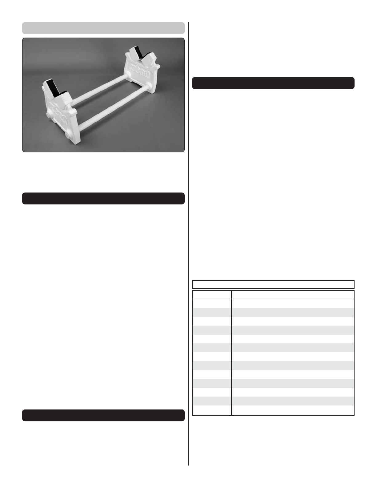
Building Stand
A building stand or cradle comes in handy during the build.
We use the Robart Super Stand II (ROBP1402) for all our
projects in R&D, and it can be seen in pictures throughout
this manual.
IMPORTANT BUILDING NOTES
● When you see the term test fi t in the instructions, it means
that you should fi rst position the part on the assembly
without using any glue, then slightly modify or custom
fi t the part as necessary for the best fi t.
● Whenever the term glue is written you should rely upon
your experience to dec ide what type of glue to use. When
a specifi c type of adhesive works best for that step, the
instructions will make a recommendation.
● Whenever just epoxy is specifi ed you may use either
30-minute (or 45-minute) epoxy or 6-minu te epox y. When
30-minute epoxy is specifi ed it is highly recommended that
you use only 30-minute (or 45-minute) epoxy, because you
will need the working time and/or the additional strength.
● Photos and sketches are placed before the step they
refer to. Frequently you can study photos in following steps
to get another view of the same parts.
● The stabilizer and wing incidences and engine thrust
angles have been factory-built into this model. However,
some technically-minded modelers may wish to check
these measurements anyway. To view this information
visit the web site at www.greatplanes.com and click on
“Technical Data.” Due to manufacturing tolerances which
will have little or no effect on the way your model will fl y,
please expect slight deviations between your model and
the published values.
KIT INSPECTION
or missing parts, use the part names exactly as they are
written in the Kit Contents list.
Great Planes Product Support
3002 N Apollo Drive, Suite 1 Ph: (217) 398-8970, ext. 5
Champaign, IL 61822 Fax: (217) 398-7721
E-mail: airsupport@greatplanes.com
ORDERING REPLACEMENT PARTS
Replacement parts for the Great Planes U-Can-Do SF are
available using the order numbers in the Replacement Parts
List that follows. The fastest, most economical service can
be provided by your hobby dealer or mail-order company.
To locate a hobby dealer, visit the Hobbico web site at www.
hobbic o.com. Ch o ose “ W here to Buy” at th e b ottom of the me n u
on the left side of the page. Follow the instructions provided
on the page to locate a U.S., Canadian or International dealer.
Parts may also be ordered directly from Hobby Services by
calling (217) 398-0007, or via facsimile at (217) 398-7721, but
full retail prices and shipping and handling charges will apply.
Illinois and Nevada residents will also be charged sales tax.
If ordering via fax, in c lude a Visa or Master Card num b er and
expiration date for payment.
Mail parts orders Hobby Services
and payments by 3002 N Apollo Drive, Suite 1
personal check to: Champaign IL 61822
Be certain to specify the order number exactly as listed in the
Replacement Parts List. Payment by credit card or personal
check only; no C.O.D.
If additional assistance is required for any reason contact
Product Support by e-mail at productsupport@greatplanes.
com, or by telephone at (217) 398-8970.
REPLACEMENT PARTS LIST
Order No. Description
GPMA4335
GPMA4336
GPMA4337
GPMA4338
GPMA4339
GPMA4340
GPMA4341
GPMA4342
GPMA4343
GPMA4344
GPMA4345
GPMA4346
GPMA4347
Fuselage
Wing / Ailerons
Horizontal Stabilizer / Elevators
Fin / Rudder
Cowl
Hatch
Landing Gear
Wheel Pants
Spinner
EP Motor Mount
Side Force Plates
Pushrods
Tail Wheel Assembly
Before starting to build, take an inventory of this kit to make
sure it is complete, and inspect the parts to make sure they
are of acceptable quality. If any parts are missing or are
not of acceptable quality, or if you need assistance with
assembly, contact Product Support. When reporting defective
5
Page 6
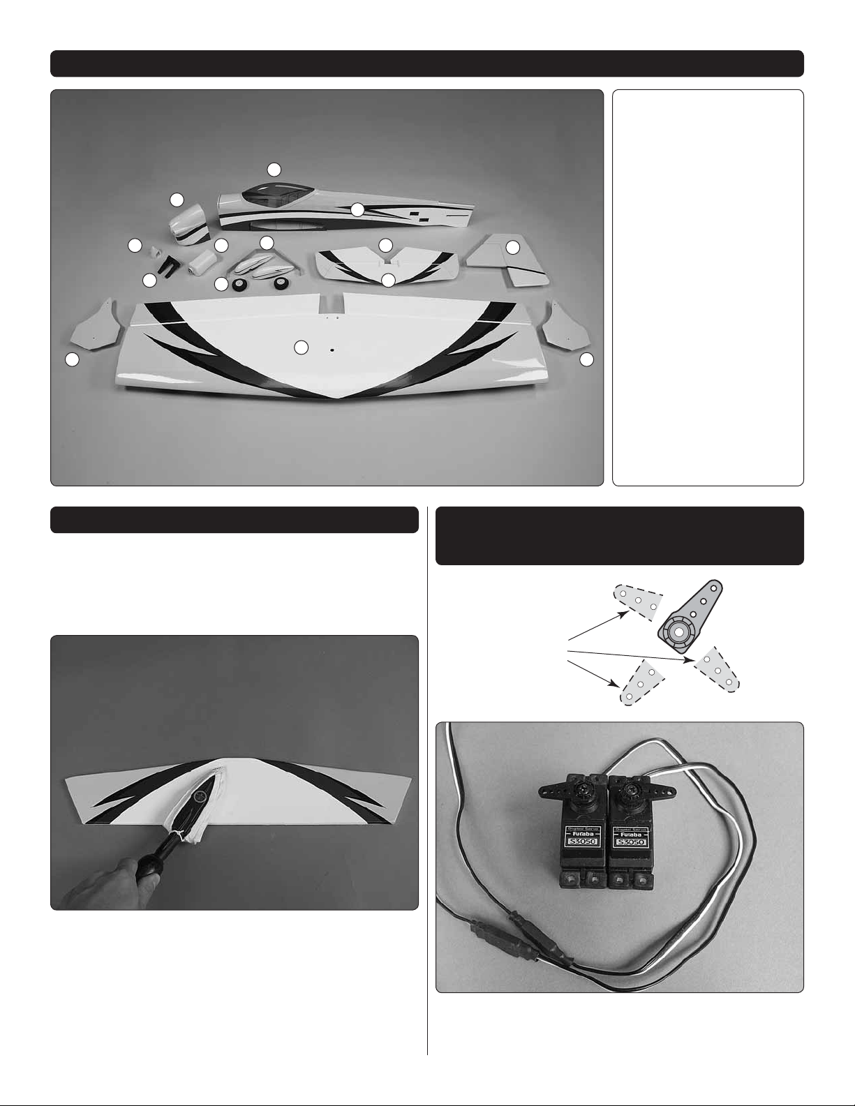
CUT OFF
UNUSED
ARMS
KIT CONTENTS
3
1
89
10
13 13
12
11
4
2
7
6
5
Kit Contents
1.
Cowl
2.
Fuselage
3.
Canopy Hatch
4.
Wing / Ailerons
5.
Vertical Fin / Rudder
6.
Horizontal Stabilizer
7.
Elevator Halves
8.
Fuel Tank
9.
Spinner
10.
Engine Mount
11.
Landing Gear
12.
Wheels
13.
Side Force Generator
PREPARATIONS
1. If you have not done so already, remove the major parts
❏
of the kit from the box and inspect for damage. If any parts
are damaged or missing, contact Product Support at the
address or telephone number listed in the “Kit Inspection”
section on page 5.
INSTALL THE AILERON SERVOS,
PUSHRODS AND BELLY PAN
❏
Use a covering ir o n with a covering sock on high h eat to t i ghten
th e covering if ne c e s sar y. Apply pres sure over sheeted areas
to thoroughly bond the covering to the wood.
2. Remove the tape and separate all the control surfaces.
1. Center your aileron servos with your radio system.
❏
Test fi t four-armed servo arms onto the servos to determine
their best orientation so that the arms are closest to being
6
Page 7
perpendicular with the servo case. Cut three arms from each
Hinge Line Hinge Line
Correct Incorrect
servo arm leaving one arm on each servo that matches
the photo. Enlarge the outer hole of each remaining arm
with a 5/64" [2mm] drill bit. Attach a 12" [305mm] servo
extension to each servo. Secure the connection using tape,
heat shrink tubing (not included) or special clips designed for
that purpose. Install the rubber grommets and eyelets onto
the servo mounting tabs.
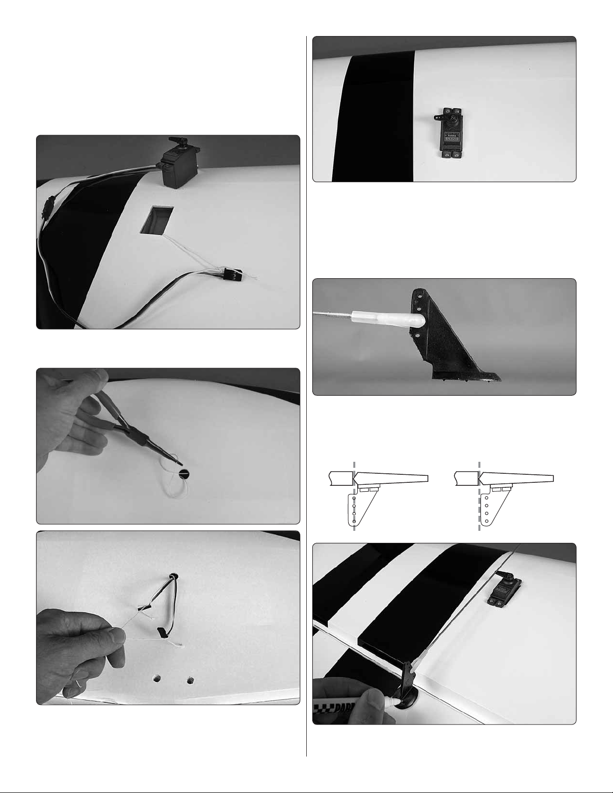
4. Fit the servos into the servo openings and drill 1/16"
❏
[1.6mm] holes through the mounting tabs on the servo cases
into the rails. Thread a servo mounting screw (included with
th e servo) into each h ole and back it out. Apply a dro p of thin
CA to each hole to harden the surrounding wood. When the
CA has dried, install the servos into the openings as shown
using the screws supplied with the servos.
2. Tie the string ends that are taped inside the wings at
❏
the aileron servo bays to the servo extension connectors.
5. Thread a nylon clevis onto two 12" [305 mm] pushrods 20
❏
com p lete turns. At tac h each clev is to the middle hole of a large
control horn. Cut off the bottom corner of each control horn.
3. Reach into the hole in the center of the top of the wing
❏
with slender needle nose pliers and grab the string. Pull the
string through the hole. Use the string to pull the servo leads
through the wing and out the hole.
6. Position a control horn onto the aileron aligning the
❏
pushrod with the outer hole of the aileron servo arm. Position
7
Page 8
the control horns over the hardwood blocks in the ailerons
Servo Horn
1/16" [1.6 mm]
Pushrod Wire
FasLink
(if you cannot see them, hold the aileron at a shallow angle
in good lighting or use a small pin to puncture the covering).
When satisfi ed, use a felt-tip pen to mark the location of the
control horn mounting holes onto the aileron. Repeat this
step for the other aileron.
7. Drill 5/64" [2mm] holes at the marks you made. Thread
❏
a #4 x 5/8" [16mm] self-tapping screw into each hole and
back it out. Apply a dro p of thin CA to each hole to harden the
surrounding wood. Install the control horns onto the ailerons
using eight #4 x 5/8" [16mm] screws.
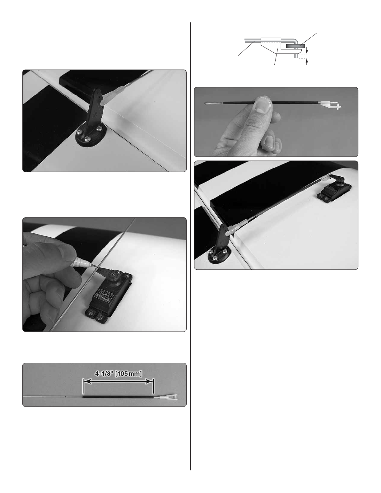
8. With the ailerons in the neutral position (use tape or
❏
small clamps to hold them in place), mark the pushrod wires
where they cross the outer holes in the servo arms.
9. Clean the area of the pushrods between the marks
❏
you made and the threads with a paper towel dampened
with denatured alcohol. Apply a thin coating of epoxy onto
the pushrods from the end of the threads to approximately
3/4" [19mm] from your marks. Slide the two 4-1/8" [105mm]
carbon tubes over the pushrods up to the pushrod threads.
Wipe away any excess epoxy with denatured alcohol and
allow the epoxy to cure undisturbed.
10. Make a 90 degree bend at the mark on each pushrod
❏
and cut off the excess pushrod 1/4" [6mm] ends beyond the
bends. Attach the pushrods to the servo arms using nylon
FasLinks. Thread the clevises up or down on the pushrods
as necessary to center the ailerons with the servo arms still
perpendicular to the servo cases. When satisfi ed, slide silicone
clevis retainers onto the ends of the clevises to secure them.
8
Page 9
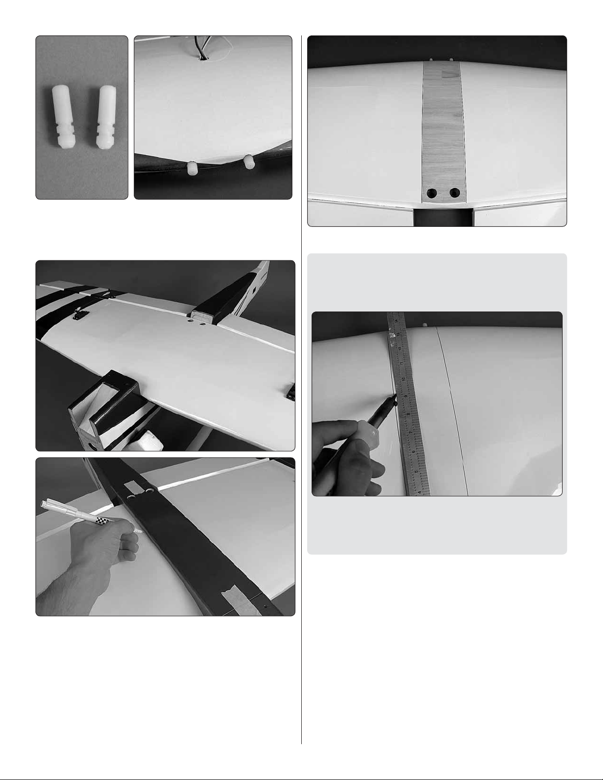
11. Locate the two nylon wing dowels. Coat the grooved
❏
ends with epoxy and fi t the dowels into the holes at the leading
edge of the wing as far as they will fi t into the holes. Wipe
away any excess epoxy with denatured alcohol.
13. Remove the covering between the lines you drew.
❏
HOW TO CUT COVERING FROM BALSA
Use a soldering iron to cut the covering from the stab. The
tip of the soldering iron doesn’t have to be sharp, but a fi ne
tip does work best. Allow the iron to heat fully.
12. Mount the wing onto the fuselage using two 1/4-20 nylon
❏
wing bolts. Fit the belly pan onto the underside of the wing,
align it with the fuselage and temporarily tape it into place.
Use a felt-tip pen to trace around the belly pan onto the wing.
Use a straightedge to guide the soldering iron at a rate that
will just melt the covering and not burn into the wood. The
hotter the soldering iron, the faster it must travel to melt a
fi ne cut. Peel off the covering.
14. Use epoxy to glue the belly pan to the wing. Take care
❏
not to glue the belly pan to the fuselage. It is recommended
to separate the forward and aft ends of the belly pan and
fuselage with wax paper before gluing it in place.
9
Page 10
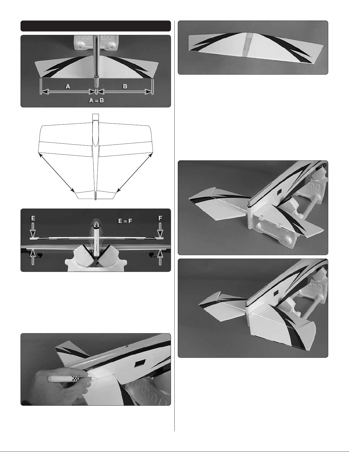
INSTALL THE TAIL SECTION
C
C = D
D
Pull the stab from the fuselage and remove the covering 1/16"
[1.6mm] inside your lines using the same technique you used
on the wing.
3. Coat the exposed wood with 30-minute epoxy (although
❏
messy, a more reliable glue joint can be attained if you also
coat the inside edges of the stab pocket). Reinstall the stab and
properly posi tion it in t he pocket. Wipe away any exc ess epoxy
with denatured alcohol and let the epoxy cure undisturbed.
When cured, the wing can be removed from the fuselage
and set aside as it will not be needed until the fi nal set up
of the plane.
1. Insert the horizontal stabilizer into the stabilizer slot and
❏
center it left and right. Align the stab so the distance between
the wing tips and stab tips are equal on both sides. Now, with
the wing still in place, stand behind the model approximately
10 feet [3m] and confi rm that the stab sits parallel with the
wing. If not, weight can be added to to the high side while
gluing the stab in place, or the stab pocket can be lightly
sanded until the stab and wing sit parallel.
2. With the stab carefully aligned from the previous step,
❏
use a fi ne felt-tip pen to trace the outline of the fuselage onto
the stab. Mark the top and bottom of the stab.
4. Stick a T-pin or something simliar through the center of
❏
six CA hinges. Insert the hinges into the slots in the trailing
edge of the stab up to the pins. Install the elevator halves
onto the other ends of the hinges. Allow approximately 3/32"
[2.4mm] gap between the ends of the stab and the elevators.
Pull the p ins out, d e fl ect the elevator halves down and apply 6
to 7 drops of thin CA glue to the center of each hing e. Flip the
plane over and apply another 6 or 7 drops to the undersides
of the hinges. When the CA glue has dried, pull on each
elevator half to confi rm they are thoroughly glued in place.
10
Page 11

5. Temporarily install the vertical fi n and rudder into the
❏
slot in the fuselage. Trace around the fuselage onto the fi n
and remove the covering just below your lines. Stick a T-pin
through the remaining CA hinge and insert the hinge into the
slot in the rudder. Test fi t the tail wheel wire into the rudder.
6. Test fi t the vertical fi n into the slot in the fuselage. Fit
❏
the CA hinge into the slot in the fuselage and the nylon tab
on the tail wheel wire into the slot below the CA hinge slot.
Make any adjustments to the slots to ensure the vertical fi n
and rudder fi t properly against the aft end of the fuse.
Coat the inside of the fi n slot with epoxy as well as the rudder
end of the tail wheel wire and the nylon tab. Fit the vertical
fi n back into place in the fuselage and the CA hinge and tail
wheel tab back into the slots. Wipe away any excess epoxy
with denatured alcoh ol. Apply 6 or 7 dro p s of thin CA to each
side of the rudder hinge. Allow the epoxy to cure undisturbed.
7. When satisfi ed with the fi t, remove the fi n and rudder.
❏
Remove the tail wheel wire from the rudder and clean the
rudder end of the wire with denatured alcohol. Apply a few
drops of oil along the hinge of the nylon tab.
8. Attach 24" [610mm] servo extensions onto the two
❏
elevator servos and the rudder servo. Be sure to secure the
extensions as you did with the aileron servos. Center the
servos with your radio system and install servo arms in the
orientations shown in the pictures. Use the hardware included
with the servos to mount them in the tail of the fuselage. Thin
CA glue should be applied to each of the servo screw holes.
11
Page 12

9. Locate the mounting blocks under the covering in the
❏
elevator halves for the elevator control horns. Position a
control horn onto each elevator half over these mounting
blocks and mark the locations for the control horn mounting
screws. Drill 5/64" [2mm] holes at your marks. Install the
control horns using four 2-56 x 5/8" [16mm] machine screws
and control horn backplates.
11. Apply a drop or two of oil onto the tail wheel axle and
❏
slide on the tail wheel. Secure it in place with a 1/8" [3.2mm]
wheel collar and 4-40 set screw. Confi rm that the tail wheel
rotates freely.
INSTALL THE MAIN LANDING GEAR
1. Install the axles onto the main landing gear legs using
❏
the large axle nuts. Orient them so the fl at spots at the ends
of the axles are facing downward.
10. The procedure for making the elevator pushrods is
❏
the same as it was for the ailerons. A 5-5/16" [135mm] and a
7-1/16" [180mm] carbon tube are included for strengthening
the elevator pushrods. The clevises should be connected to
the fourth outer holes from the control horn bases. Assemble
and install the rudder pushrod in the same manner using the
remaining 5-7/8" [150mm] carbon tube.
2. Slide a 5/32" [4mm] wheel collar onto the axle and
❏
tighten it against the base of the axle using a 6-32 x 1/4"
[6mm] socket head cap screw and thread locking compound.
Apply a drop or two of oil to the axle and then install a main
wheel. Install another 5/32" [4mm] wheel collar and 6-32 x 1/4"
[6mm] SHCS onto the axle against the fl at spot. Confi rm that
the wheel rotates freely. Repeat this step for the other axle.
12
Page 13

3. Install the wheel pants onto the landing gear using four
❏
2-56 x 1/2" [13mm] machine screws, four #2 lock washers,
four #2 fl at washers and thread locking compound. The angled
edge of the landing gear legs is the AFT edge.
marks. Be sure to drill the holes as shown in the picture. It is
recommended to start with a small drill bit and work your way
up in size to 11/6 4" [4.4mm]. Doing th is will im prove accuracy
in the positioning of the holes and will reduce the amount of
tear-out from the backside of the holes. When completed,
install 6-32 blind nuts into the holes. Draw them fully into the
holes by threading a 6-32 x 5/8" [15.9mm] screw and #6 fl at
washer into each hole and tightening the screw.
4. Attach the gear to the fuselage using two 6-32 x 3/4"
❏
[19mm] machine screws, two #6 lock washers, two #6 fl at
washers and thread locking compound.
INSTALL THE POWER SYSTEM
Brushless Motor
This section only contains information relating to the installation
of a brushless power system. Skip this section if you plan to
install a glow engine.
2. Use a sharp hobby knife to fi nish cutting out the ESC
❏
tray slots and the cooling hole. Note that the fi rewall is made
up of two layers of plywood. The cooling hole is removed from
both layers. The three slots are removed from only one layer.
1. Drill four 11/64" [4.4mm] holes at the marks on the fi rewall
❏
for the brushless motor mount. Note that there are two sets of
3. Locate the pieces that make up the brushless motor
❏
mount. Begin the assembly by gluing the two front pieces
together, making sure that the edges are fl ush with each other.
13
Page 14

Press four 6-32 blind nuts into the holes as shown and apply
some glue around each nut to prevent them from coming loose.
4. Glue the two rear pieces together. Assemble the rest
❏
of the mount being sure to thoroughly glue all the joints
together. We suggest using thin CA on all the outside joints
and then running a bead of medium or thick CA along all the
inside joints.
5. A short length of 1/8" [3.2mm] wood dowel is included.
❏
Cut four 1/ 2 " [13mm] pieces from the d owel. Drill 1/ 8" [3.2mm]
holes approximately 3/8" [9.5mm] deep into the center of each
forward tab. Glue a piece of dowel into each hole and sand
them fl ush with the sides of the motor mount.
7. Install the aluminum ‘X’ mount and prop adapter onto
❏
your brushless motor using the screws included with the
motor and thread locking compound. Attach the motor onto
the front of the brushless motor mount using four 6-32 x 5/8"
[15.9mm] machine screws, four #6 fl at washers, four #6 lock
washers, and thread locking compound.
6. Attach the brushless motor mount to the fi rewall using
❏
four 6-32 x 3 /4" [19mm] machine s crews, four # 6 fl at washers,
four #6 lock washers, and thread locking compound.
8. Locate the six plywood pieces that make up the ESC
❏
tray. Glue them together as shown.
9. It is recommended to make a 3" [76mm] battery lead
❏
extension to make connecting your pack easier. In order to
14
Page 15

make the extension shown you will need to purchase: W.S.
Deans® Female Ultra Plug® w/Pigtail (WSDM3010) and W.S.
Deans® Male Ultra Plug® (2) (WSDM1302). To make the
extension, cut the wires on the pigtail to a length of 3" [76mm]
and strip the insulation 3/16" [4.8mm] from the end of the
wires. Slide pieces of heat shrink tubing onto the wires and
solder the wires onto the male connector.
10. Connect your battery lead extension to the ESC. Mount
❏
the ESC to the ESC tray with three #4 x 1/2" [13mm] self-
tapping screws and three #4 fl at washers. If you are using
an ESC other than the one recommended, you may need to
modify the tray or mount the ESC in a different manner.
11. Connect the motor wires to the ESC, route the battery
❏
lead and receiver lead through the cooling hole in the fi rewall
and thoroughly glue the ESC tray into the slots in the fi rewall.
12. Glue the battery tray in the location shown. When the
❏
glue has hardened, pull on the tray to confi rm it has been
securely glued in place.
13. Apply a coating of epoxy down the center of the battery
❏
tray and allow it to cure completely. Cut pieces from the hook
si d e of the i nc luded self-adhesive hook an d loop material and
apply them over the epoxy as shown.
15
Page 16

14. Make 6" [152mm] battery straps by cutting pieces
❏
from the included non-adhesive hook and loop material and
overlapping the mating ends by 1" [25.4mm]. Feed the straps
through the slots shown in the photo.
Glow Engine
The following section only contains information relevant
to installing a glow engine. If you have already installed a
brushless motor then skip this section. The O.S. .65 AX engine
is shown in this section with the stock muffl er. Other model
engines will install in a similar manner. If your throttle arm is
in a different position than what is shown in the photos then
you will need to adjust the location of the throttle pushrod
accordingly.
1. If you are mounting a .55AX or .65AX engine in the
❏
angled orientation, drill a hole for the throttle pushrod in the
fi rewall in the location shown using an 11/64" [4.4 mm] drill bit.
If you are installing a different engine or an inverted engine,
you will need to locate this hole according to the position of
the throttle arm on your carburetor. Be sure you are clearing
the fuel tank area when drilling the hole.
2. Glue the fuel tank support in place. Be sure the notch
❏
for the throttle pushrod tube aligns with the hole you drilled
in the previous step.
This section shows the stock muffl er being used and therefore
the angled engine mount pattern was chosen to align the
muffl er in the cavity o n the bottom of the fuse lage. If you plan
to use a 4-stroke engine or a Pitts style muffl er, then you can
use the engine mount pattern that has the center lines running
horizontally and vertically depending on the engine model. A
.55AX O.S. engine stock muffl er will fi t in the cavity without
the need to cut away the bottom of the cowl. The .65AX stock
muffl er will also fi t in the cavity; however, the majority of the
bottom of the cowl will need to be cut away because the
muffl er will protrude slightly lower than the bottom line of the
fuselage. The .65AX can also be mounted inverted with the
muffl er located on the side of the fuselage (not shown). Choose
the engine orientation that works for you before proceeding.
3. Cut the included outer pushrod tube to 9" [229 mm].
❏
16
Page 17

4. Insert the pushrod tube through the hole you drilled in
❏
the fi rewall and into the notch in the fuel tank support. The
pushrod tube should stick out past the fi rewall approximately
1/4" [6.4mm]. Glue the tube to the fi rewall and into the notch
with CA glue. If you have positioned the pushrod in a location
different than what is shown in the picture, you may need to
modify the fuel tank support to accommodate the pushrod
tube. With glue in hand, fi ll the perforated cutout lines for the
cooling hole and ESC tray slots in the fi rewall. These cutouts
are for the brushless installation only and should be glued in
place for a glow engine setup.
6. Drill 11/64" [4.4mm] holes at the angled mounting pattern
❏
on the fi rewall. For accuracy and to avoid tearing the wood
we suggest starting with a 1/16" [1.6mm] bit and working
up in bit size. Install four 6-32 blind nuts using a 6-32 x 3/4"
[19mm] machine screw and a #6 fl at washer to draw them
tight into the holes. The blind nut that you cut in step 5 should
go in the top hole.
5. Grind or cut off a portion of one of the 6-32 blind nuts
❏
as shown.
17
Page 18

7. The fuel tank can be assembled as a two line system
❏
consisting of a vent (pressure) line to the muffl er and a
carb line. Filling and emptying of the tank would need to be
done through the carb line, or an optional fuel fi ll valve (not
included). The tank can also be assembled as a three line
system (shown) having a vent line, carb line, and fi ll line. If
installing a fi ll line, puncture the top of the stopper above the
sealed off fuel tube hole. The fi ll and carb lines should extend
out 1/2" [13mm] beyond the stopper and the vent line should
be bent upwards and left uncut. With the tubes installed in
the stopper, fi t the stopper plates loosely in place with the 3
x 25mm phillips screw to hold the assembly together.
9. Loop the strap through the slots behind the fuel tank
❏
support. Fit the fuel tank onto the fuel tank support with the
fuel tank neck through the hole in the fi rewall (be sure that
the correct side of the tank is facing up). Draw the strap ends
around the tank and confi rm that the tank is secure.
10. Locate the fuel tank brace. Position it behind the fuel
❏
tank as shown and glue it into place.
8. Make a strap 12" [305mm] long by overlapping the
❏
mating ends of the inclu d e d hook and l o o p mater ial 1" [25mm] .
11. Loosely attach the engine mount halves to the fi rewall
❏
using four 6-32 x 3/4" [19mm] machine screws, four #6 lock
18
Page 19

washers, four #6 fl at washers and thread locking compound.
The engine mount should be angled down and to the right.
Fit your engine between the mount halves and slide them
together against the crankcase. Remove the engine and
fi nish tightening the mount screws.
12. Attach 6" [152mm] pieces of fuel tubing to each of the
❏
three fuel tank lines.
14. Use four 6-32 x 3/4" [19mm] machine screws, four #6
❏
lock washers and four #6 fl at washers to attach the engine
to the engine mount.
13. Position the engine onto the mount so the face of the
❏
drive washer is 5" [127mm] from the fi rewall. Use a Dead
Center Hole Locator (GPMR8130) to mark the location of
the engine tab mounting holes onto the engine mount rails.
15. Mount the muffl er to the engine and connect the vent
❏
and carb fuel lines to the engine. Plug the vent/ fi ll line (if
applicable) with the included nylon fuel line plug. The plug
should stay in place during fl ight and only needs to be removed
to fi ll or drain the fuel tank.
16. Mount the throttle servo in the middle of the servo tray.
❏
The servo spline should be toward the rear of the plane. Be
sure to reinforce the mount screw holes with thin CA.
19
Page 20

17. Bend the throttle pushrod so that it can reach the
❏
throttle arm on the carburetor without contacting any part of
the engine or mount. Thread a nylon clevis onto the pushrod
and slide a silicone clevis retainer onto the clevis. Insert the
pushrod into the outer pushrod tube and connect the clevis
to the outer hole in the throttle arm.
throttle servo perpendicular to the servo case (be sure to
install the servo arm screw). Adjust the carb barrel so that it
is close to 50% open and tighten the set screw in the screw-
lock connector. Test the operation of the throttle using your
transmitter and confi rm that the carb barrel properly opens and
closes. Make any adjustments to the pushrod as necessary.
When satisfi ed, cut off the excess pushrod 1/4" [6.4mm] aft
of the screw-lock connector.
INSTALL THE RECEIVER,
BATTERY, AND SWITCH
18. Cut all but one of the arms from a servo arm. Install a
❏
screw-lock pushrod connector into the hole in the remaining
arm that is approximately 27/64" [10.5mm] from the center
of the servo arm. Secure the screw-lock connector with a
screw-lock connector retainer. Loosely thread a 4-40 set
screw into the screw-lock connector.
19. Center the throttle servo using your radio system
❏
(50% throttle). Insert the aft end of the throttle pushrod into
the screw-lock connector and attach the servo arm to the
1. Wrap your re c e iver battery in 1/ 4" [6.4m m ] foam rub b er
❏
(not included) to protect it from motor vibration. If you have
powered your model with a brushless motor, then a standard
AA 4.8V fl at receiver pack will fi t at the aft end of the battery
tray. If you installed a glow engine, a LiFe battery (lithium
iron phosphate LiFePO4) can also be used because there
is more space on the tray available behind the fuel tank. Cut
pieces from the hook and loop material to make straps to
secure the battery to the tray.
20
Page 21

2. Strap your receiver behind the throttle servo bay. Be
❏
sure that there is foam rubber beneath the receiver.
receptable fi ts well in front of the switch. Note: If you are
using a LiFe receiver pack then the charge jack receptable
should be used for monitoring pack voltage, or charging in
conjunction with the balancing lead. Do not attempt to charge
a LiFe battery through this jack without also conencting to the
balance lead! The balancing connector will remain accessible
through the canopy hatch. To help prevent inadvertent charging
of a LiFe battery through this jack without also connecting the
balancing connector, we identifi ed the battery type installed
in our model with a LiFe Source decal.
3. Locate the 2" [51mm] piece of antenna tube. Cut the
❏
tube in half and glue the pieces to the fuselage sides in an
orientation so that the antenna ends are 90 degrees to each
other (see your radio manual for additional information about
antenna placement). Insert the antenna ends into the tubes.
5. Connect your servos and switch to the receiver. If
❏
you installed a brushless motor, you will need to attach a 6"
[152mm] servo extension to the ESC lead. Bundle the excess
wires together using tie straps or something similar. We used
the underside of the receiver battery strap to hold the servo
lead extension and switch harness connector out of the way
of the wing saddle area.
FINISH THE MODEL
4. Mount your switch harness on the side of the fuselage
❏
opposite your muffl er. If your muffl er is mounted in the fuselage
cavity then either side will work fi ne. An optional charge jack
1. If you installed a glow engine, make card stock templates
❏
of any engine component that you will need to trim the cowl. We
suggest starting with the minimum sized opening necessary to
clear the engine parts. Then, as you test fi t the cowl in place,
you will need to enlarge the openings accordingly in order
to be able to fi t the cowl in place. If you installed a brushless
motor then you will not need to make any cutouts in the cowl.
21
Page 22

2. If you installed a glow engine, locate the plywood dummy
❏
engine parts and glue them together as shown. This dummy
engine is provided as an aid to mount the cowl accurately
without the engine in place.
tape pieces exactly where the cowl mounting screw holes
will be drilled. The holes should be located in the center of
the thickness of the fi rewall. Use a ruler to draw straight lines
exactly 4" [102mm] long aft of your cowl screw hole marks.
3. Temporarily remove the engine mount and engine from
❏
the fi rewall. Attach the dummy engine to the fi rewall. Only two
6-32 x 1/2" [13mm] screws are required to hold the dummy
engine in place. Put a few washers on the bottom screw to
prevent the end of the screw from contacting the fuel tank.
The top screw will go over the top of the tank so washers are
not required.
4. Put four pie c e s of mask i ng tape onto the fu s elage sid e s
❏
in the locations shown (two on each side). Mark onto the
5. Fit the cowl onto the fuselage so that the prop adapter
❏
face (or the dummy engine front) is approximately 3/32"
[2.4mm] forward of the front of the cowl. Align the colors on
the cowl with the MonoKote color scheme on the fuselage
and temporarily tape the cowl in place when satisfi ed with
its position. From the lines you drew on the tape, transfer the
cowl mounting hole marks onto the cowl. Drill 1/16" [1.6mm]
holes through the marks on the cowl and into the fi rewall.
Use the templates you made in step 1 to trace the patterns
onto the cowl.
22
Page 23

6. Remove the cowl and dummy engine (if applicable) from
❏
the fuselage. Use a rotary tool to cutout any openings in the
cowl necessary for your power system installation. Reinstall
the engine if you removed it from the fi rewall. Thread a #2
x 1/2" [13mm] screw into each cowl mounting hole in the
fuselage a nd back it out. Apply a drop of t hin CA glue to each
hole and allow the glue to harden. Enlarge the holes in the
cowl to 3/ 32" [ 2.4mm]. Test fi t the cowl onto the fuselage and
adjust your cutouts as necessary until the cowl is a good fi t.
When satisfi ed, install the cowl using four #2 x 1/2" [13mm]
screws and four #2 fl at washers.
8. If you have not already discovered how to install the
❏
canopy hatch, align the two pins at the front of the hatch
with the two holes in the fi rewall. Lay the aft end of the hatch
down against the fuselage, aligning the tabs into the slots.
Lock the hatch in place by sliding the hatch back, which will
engage the magnets.
7. Install the propeller and spinner onto the motor. You may
❏
need to enlarge the hole in the prop and spinner backplate
with a reamer or drill to match the prop shaft of your power
system. It may also be necessary to enlarge the cutouts in
the spinner cone to fi t your prop. The cone should not contact
the prop at any point in the cut out.
9. Admire your completed U-Can-Do SF ARF! Prepare to
❏
move on to the fi nal sections for applying the decals, getting
the control throws set and the plane balanced.
23
Page 24

Optional Side Force Generators
Side force generators are included as an optional addition. The
side force generators are designed to reduce wing walking in
high-alpha maneuvers and reduce the amount of rudder input
needed for knife-edge fl ight. The side force generators are
easily installed and removed at your fl ying site. We recommend
fl ying the model both with and without them to get a comparison
of their benefi ts to your fl ying style and skill.
2. Install the side force generators onto the wing tips using
❏
four 4-40 x 1/2” [13mm] machine screws, four #4 fl at washers
and thread locking compound.
Apply the Decals
1. Use scissors or a sharp hobby knife to cut the decals
❏
from the sheet.
1. Trim the covering from the screw holes in the side force
❏
generators. You will also need to locate the blind nuts on the
wing tips and trim the covering from them.
2. Be certain the model is clean and free from oily
❏
fi ngerprints and dust. Prepare a dishpan or small bucket
with a mixture of liquid dish soap and warm water—about one
teaspoon of soap per gallon of water. Submerse the decal
in the soap and water and peel off the paper backing. Note:
Even though the decals have a “sticky-back” and are not the
water transfer type, submersing them in soap & water allows
accurate positioning and reduces air bubbles underneath.
3. Position decal on the model where desired. Holding the
❏
decal down, use a paper towel to wipe most of the water away.
4. Use a piece of soft balsa or something similar to
❏
squeegee remaining water from under the decal. Apply the
rest of the decals the same way.
GET THE MODEL READY TO FLY
Check the Control Directions
1. Turn on the transmitter and receiver and center the trims.
❏
If necessary, remove the servo arms from the servos and
reposition them so they are centered. Reinstall the screws
that hold on the servo arms.
2. With the transmitter and receiver still on, check all the
❏
control surfaces to see if they are centered. If necessary, adjust
the clevises on the pushrods to center the control surfaces.
If you installed retracts, confi rm their operation and that they
lock both in the up and down positions.
24
Page 25

FULL
THROTTLE
RUDDER
MOVES
RIGHT
ELEVATOR
MOVES DOWN
RIGHT AILERON
MOVES UP
LEFT AILERON
MOVES DOWN
4-CHANNEL RADIO SET UP (STANDARD MODE 2)
3. Make certain that the control surfaces and the throttle
These are the recommended control surface throws:
ELEVATOR
HIGHLOW
1"
[25mm]
15°
3/4"
[19mm ]
11°
15/16"
[24mm]
12°
5/8"
[16mm]
8°
2-1/2"
[64mm]
23°
1-1/8"
[29mm]
10°
RUDDER
AILERONS
3D
2-5/16"
[59mm]
36°
1-1/2"
[38mm]
20°
4"
[102 mm]
39°
Up & Down
Up & Down
Right & Left
The pushrod farther out
means More Throw
The pushrod closer in
means Less Throw
The pushrod farther out
means Less Throw
The pushrod closer in
means More Throw
At the Servos
At the Control Surfaces
❏
respond in the correct direction as shown in the diagram.
If any of the controls respond in the wrong direction, use
the servo reversing in the transmitter to reverse the servos
connected to those controls. Be certain the control surfaces
have remained centered. Adjust if necessary.
IMPORTANT: The U-Can-Do SF has been extensively
fl own and tested to arrive at the throws at which it fl ies best.
Flying your model at these throws will provide you with the
greatest chance for successful fi rst fl ights. If, after you have
become accustomed to the way the U-Can-Do SF fl ies, you
would like to change the throws to suit your taste, that is fi ne.
However, too much control throw could make the model
diffi cult to control, so remember, “more is not always better.”
Set the Control Throws
Use a Great Planes AccuThrow (or a ruler) to accurately
measure and set the control throw of each control surface
as indicated in the chart that follows. If your radio does not
have dual rates, we recommend setting the throws at the
low rate setting.
NOTE: The throws are measured at the widest part of the
elevators, rudder and ailerons.
1. If necessary, adjust the location of the pushrod on the
❏
servo arm or on the elevator horn, or program the ATVs in
your transmitter to increase or decrease the throw according
to the measurements in the control throws chart.
25
Page 26

Proper Pushrod Hookup;
SERVO ARM
OFFSET
Pivot point
CONTROL
HORN OFFSET
Pushrod far out
on the servo arm…
…pushrod close in
on the control horn.
Extremely Dangerous
Pushrod Hookup
“Closest in”
on servo arm
“Farthest out”
on control horn
Preferred
Pushrod Hookup
Move the pushrod
farther out on
the servo arm…
…But leave the pushrod
in the farthest out location
on the control horn.
Acceptable
Pushrod Hookup
Avoiding Flutter, Maximizing Servo
Output Torque
When connecting pushrods and setting up your control throws,
it is critically important to use proper pushrod geometry—
that is the distance from the pushrod on the servo arm to the
center of the output shaft (servo arm offset) compared to
the distance from the pushrod on the control horn to the pivot
point (control horn offset).
Here is an optimum pushrod setup—the pushrod is “close
in” on the servo arm and “far out” on the control horn. This
situation gives the greatest mechanical advantage of the
servo over the control surface which will increase the servo’s
centering capabilities and output torque, minimize any free
play in the system and allow high ATV settings for optimum
servo resolution and positive control “feel.” Note: When the
pushrod is “close in” on the servo arm, make certain the servo
arm can travel through its full range of movement without the
pushrod (or clevis or other type of connector) interfering with
the servo arm, output shaft or servo case.
One particularly dangerous situation arises when the pushrod
on the servo arm is too “far out” and the pushrod on the
control horn is too “close in.” This setup is usually chosen by
pilots who are trying to achieve maximum, “monster” control
throws for 3D fl ight. But with your pushrods set up this way,
any free play (slop) in the linkages or servo will be greatly
magnifi ed, possibly causing destructive control surface fl utter.
Additionally, if you have to turn your ATV’s way down for
“normal” throw, the result will be poor resolution and poor
servo holding/centering capabilities. More importantly, too
much force may be transmitted back to the servo, possibly
causing control surface blowback, stripped servo gears or
stripped servo arms—the latter two likely causing a crash.
If the optimum situation doesn’t provide enough control throw,
the pushrod may be moved inward on the control horn, but
it’s better to go farther out on the servo arm because this
will introduce less free play than the alternative. Only after
moving the pushrod all the way out on the servo arm, if you
still can’t get the throw required, you’ll have to resort to moving
the pushrod closer in on the control horn. Note: If you have
a computer radio, it is always desirable to set your ATV’s to
100% (or as near 100% as possible to achieve the control throw
required). If setting up a model that requires extraordinary
control surface throw (for 3D fl ying for example), start by
“maxing-out” your ATV’s (typically 130% – 140%). Then, the
dual rates in your “normal ” fl ight m ode will still be acc eptably
high (70% – 80%) for good servo resolution.
2. Referring to the Proper Pushrod Hookup illustrations
❏
above, adjust the location of the pushrod on the servo
arm or on the elevator horn and program the ATVs in your
transmitter to increase or decrease the throw according to
the measurements in the control throws chart.
26
Page 27

3. Measure and set the low rate elevator throws and the
❏
high and low rate throws for the rest of the control surfaces
the same way.
Balance the Model (C.G.)
More than any other factor, the C.G. (balance point) can
have the greatest effect on how a model fl ies, and may
determine whether or not your fi rst fl ight will be successful.
If you value this model and wish to enjoy it for many fl ights,
DO NOT OVERLOOK THIS IMPORTANT PROCEDURE.
A model that is not properly balanced will be unstable and
possibly unfl yable.
At this st age the model should be i n ready-to-fl y condition with
all of the systems in place including the engine or brushless
motor, landing gear, and the radio system (and battery pack
if applicable).
1. Use a fe lt-tip p en or 1/8" [3mm] -wi d e tape to accurate ly
❏
mark the C.G. on the top of the wing on both sides of the
fuselage. The C.G. is located 5-1/2" [140 mm] back from the
leading edge of the wing.
This is where your model should balance for the fi rst fl ights.
Later, you may wish to experiment by shifting the C.G. up
to 1" [25 mm] forward or 3/4" [19 mm] back to change the
fl ying characteristics. Moving the C.G. forward may improve
the smoothness and stability, but the model may then
require more speed for takeoff and make it more diffi cult
to slow for landing. Moving the C.G. aft makes the model
more maneuverable, but could also cause it to become too
di f fi cult to c o ntrol. In any c ase, start at the recommended
balance point and do not at any time balance the model
outside the specifi ed range.
be added to the nose to balance. If the nose drops, the model
is “nose heavy” and the battery pack and /or receiver must be
shifted aft or weight must be added to the tail to balance. If
possible, relocate the battery pack and receiver to minimize or
eliminate any additional ballast required. If additional weight is
required, nose weight may be easily added by using a “spinner
weight” (GPMQ4645 for the 1 oz. [28g] weight, or GPMQ4646
for the 2 oz. [57g] weight). If spinner weight is not practical or
is not enough, use Great Planes (GPMQ4485) “stick-on” lead.
A good place to add stick-on nose weight is to the fi rewall
(d o n’t attach weight to the cow l —it i s not intended to support
weight). Begin by placing incrementally increasing amounts
of weight on the bottom of the fuse over the fi rewall until the
model balances. Once you have determined the amount of
weight required, it can be permanently attached. If required,
tail weight may be added by cutting open the bottom of the
fuselage and gluing it permanently inside.
Note: Do not rely upon the adhesive on the back of the lead
weight to permanently hold it in place. Over time, fuel and
exhaust residue may soften the adhesive and cause the
weight to fall off. Use #2 sheet metal screws, RTV silicone
or epoxy to permanently hold the weight in place.
4. IMPORTANT: If you found it necessary to add any
❏
weight, recheck the C.G. after the weight has been installed.
Balance the Model Laterally
1. With the wing level, have an assistant help you lift the
❏
model by the engine propeller shaft and the bottom of the
fuse under the TE of the fi n. Do this several times.
2. If one wing always drops when you lift the model, it means
❏
that side is heavy. Balance the airplane by adding weight
to the other wing tip. An airplane that has been laterally
balanced will track better in loops and other maneuvers.
2. With the wing attached to the fuselage, all parts of the
❏
model installed (ready to fl y) and an empty fuel tank, place
the model on a Great Planes CG Machine upside down, or
lift it at the balance point you marked.
3. If the tail drops, the model is “tail heavy” and the battery
❏
pack and / or receiver must be shifted forward or weight must
PREFLIGHT
Identify Your Model
No matter if you fl y at an AMA sanctioned R/C club site or if
you fl y somewhere on your own, you should always have your
name, address, telephone number and AMA number on or
inside your model. It is required at all AMA R/C club fl ying sites
and AMA sanctioned fl ying events. Fill out the identifi cation
tag on page 32 and place it on or inside your model.
Charge the Batteries
Follow the battery charging instructions that came with your
radio control system to charge the batteries. You should
always charge your transmitter and receiver batteries the night
before you go fl ying, and at other times as recommended by
the radio manufacturer.
27
Page 28

CAUTION: Unless the instructions that came with your
radio system state differently, the initial charge on new
transmitter and receiver batteries should be done for 15
hours using the slow-charger that came with the radio
system. This will “condition” the batteries so that the next
charge may be done using the fast-charger of your choice.
If the initial charge is done with a fast-charger the batteries
may not reach their full capacity and you may be fl ying with
batteries that are only partially charged.
Balance Propellers
Carefully balance your propeller and spare propellers before
you fl y. An unbal anced prop can be the sin g le most si g nifi cant
cause of vibration that can damage your model. Not only
will engine mounting screws and bolts loosen, possibly with
disastrous effect, but vibration may also damage your radio
receiver and battery. Vibration can also cause your fuel to
foam, which will, in turn, cause your engine to run hot or quit.
We use a Top Flite Precision Magnetic Prop Balancer
(TOPQ5700) in the workshop and keep a Great Planes
Fingertip Prop Balancer (GPMQ5000) in our fl ight box.
Ground Check
If the engine is new, follow the engine manufacturer’s
instructions to break-in the engine. After break-in, confi rm
that the engine idles reliably, transitions smoothly and rapidly
to full power and maintains full power—indefi nitely. After you
run the engine on the model, inspect the model closely to
make sure all screws remained tight, the hinges are secure,
the prop is secure and all pushrods and connectors are secure.
model, using hand signals to show you what is happening. If
the control surfaces do not respond correctly, do not fl y! Find
and correct the problem fi rst. Look for loose servo connections
or broken wires, corroded wires on old servo connectors,
poor solder joints in your battery pack or a defective cell, or
a damaged receiver crystal from a previous crash.
ENGINE SAFETY PRECAUTIONS
Failure to follow these safety precautions may result
in severe injury to yourself and others.
Keep all engine fuel in a safe place, away from high heat,
sparks or fl ames, as fuel is very fl ammable. Do not smoke
near the engine or fuel; and remember that engine exhaust
gives off a great deal of deadly carbon monoxide. Therefore
do not run the engine in a closed room or garage.
Get help from an experienced pilot when learning to operate
engines.
Use safety glasses when starting or running engines.
Do not run the engine in an area of loose gravel or sand; the
propeller may throw such material in your face or eyes.
Keep your face and body as well as all spectators away fr om
the plane of rotation of the propeller as you start and run the
engine.
Keep these items away from the prop: loose clothing, shirt
sleeves, ties, scarves, long hair or loose objects such as
pencils or screwdrivers that may fall out of shirt or jacket
pockets into the prop.
Use a “chicken stick” or electric starter to start the engine.
Do not use your fi ngers to fl ip the propeller. Make certain the
glow plug clip or connector i s secure so th at it will n ot pop of f
or otherwise get into the running propeller.
Make all engine adjustments from behind the rotating propeller.
The engine gets hot! Do not touch it during or right after
operation. Make sure fuel lines are in good condition so fuel
will not leak onto a hot engine, causing a fi re.
To stop a glow engine, cut off the fuel supply by closing
off the fuel line or following the engine manufacturer’s
recommendations. Do not use hands, fi ngers or any other
body part to try to stop the engine. Do not throw anything
into the propeller of a running engine.
AMA SAFETY CODE
Range Check
Ground check the operational range of your radio before the
fi rst fl ight of the day. With the transmitter antenna collapsed
and the receiver and transmitter on, you should be able to walk
at least 100 feet away from the model and still have control
(if using a 2.4GHz radio system, refer to the radio manual for
the range checking procedure). Have an assistant stand by
your model and, while you work the controls, tell you what the
control surfaces are doing. Repeat this test with the engine
running at various speeds with an assistant holding the
Read and abide by the following excerpts from the Academy
of Model Aeronautics Safety Code. For the complete Safety
Code refer to Model Aviation magazine, the AMA web site or
the Code that came with your AMA license.
General
1) I will not fl y my model aircraft in sanctioned events, air shows,
or model fl ying demo nstrations u ntil i t has been proven to be
airworthy by having been previously, successfully fl ight tested.
28
Page 29

2) I will not fl y my model aircraft higher than approximately
400 feet within 3 miles of an airport without notifying the
airport operator. I will give right-of-way and avoid fl ying in the
proximity of full-scale aircraft. Where necessary, an observer
shall be utilized to supervise fl ying to avoid having models fl y
in the proximity of full-scale aircraft.
3) Where established, I will abide by the safety rules for the
fl ying site I use, and I will not willfully and deliberately fl y my
models in a careless, reckless and/or dangerous manner.
5) I will not fl y my model unless it is identifi ed with my name
and address or AMA number, on or in the model. Note: This
does not apply to models while being fl own indoors.
7) I will n ot operate models w ith pyr otechnics (a ny dev i c e that
explodes, burns, or propels a projectile of any kind).
Radio Control
1) I will have completed a successful radio equipment ground
check before the fi rst fl ight of a new or repaired model.
2) I will not fl y my model aircraft in the presence of spectators
until I become a qualified flier, unless assisted by an
experienced helper.
3) At all fl ying sites a straight or curved line(s) must be
established in front of which all fl ying takes place with the
other side for spectators. Only personnel involved with fl ying
the aircraft are allowed at or in the front of the fl ight line.
Intentional fl ying behind the fl ight line is prohibited.
4) I will operate my model using only radio control frequencies
currently allowed by the Federal Communications Commission.
5) I will not knowingly operate my model within three miles
of any pre-existing fl ying sit e exc e pt in acco rdance with
the frequency sharing agreement listed [in the complete
AMA Safety Code].
9) Under no circumstances may a pilot or other person touch
a powered model in fl ight; nor should any part of the model
other than the landing gear, intentionally touch the ground,
except while landing.
CHECK LIST
During the last few moments of preparation your mind may
be elsewhere anticipating the excitement of the fi rst fl ight.
Because of this, you may be more likely to overlook certain
checks and procedures that should be performed before the
model is fl own. To help avoid this, a check list is provided to
make sure these important areas are not overlooked. Many
are covered in the instruction manual, so where appropriate,
refer to the manual for complete instructions. Be sure to
check the items off as they are completed (that’s why it’s
called a check list!).
3. Extend your receiver antenna (if applicable).
❏
4. Balance your model laterally as explained in the
❏
instructions.
5. Use threadlocking compound to secure critical fasteners
❏
such as the set screws that hold the wheel axles to the struts,
screws that hold the carburetor arm (if applicable), screw-lock
pushrod connectors, etc.
6. Add a drop of oil to the axles so the wheels will turn freely.
❏
7. Make sure all hinges are securely glued in place.
❏
8. Reinforce holes for wood s crews w ith thin CA wher e
❏
appropriate (servo mounting screws, cowl mounting
screws, etc.).
9. Confi rm that all controls operate in the correct direction
❏
and the throws are set up according to the manual.
10. Make sure there are silicone retainers on all the clevises
❏
and that all servo arms are secured to the servos with the
screws included with your radio.
11. Secure connections between servo wires and
❏
Y-connectors or servo extensions, and the connection between
your battery pack and the on/off switch with vinyl tape, heat
shrink tubing or special clips suitable for that purpose.
12. Make sure any servo extension cords you may
❏
have used do not interfere with other systems (servo arms,
pushrods, etc.).
13. Secure the pressure tap (if used) to the muffl er with
❏
high temp RTV silicone, thread locking compound or J.B. Weld.
14. Make sure the fuel lines are connected and are
❏
not kinked.
15. Balance your propeller (and spare propellers).
❏
16. Tighten the propeller nut and spinner.
❏
17. Place your name, address, AMA number and telephone
❏
number on or inside your model.
18. Cycle your receiver battery pack (if necessary) and
❏
make sure it is fully charged.
19. If you wish to photograph your model, do so before
❏
your fi rst fl ight.
20. Range check your radio when you get to the fl ying fi eld.
❏
FLYING
The U-Can-Do SF is a great-fl ying model that fl ies smoothly
an d predictably. The U- Can-Do SF does n ot, however, possess
the self-recovery characteristics of a primary R/C trainer and
should be fl own only by experienced R/C pilots.
Fuel Mixture Adjustments
1. Check the C.G. according to the measurements provided
❏
in the manual.
2. Be certain the battery and receiver are securely mounted
❏
in the fuse. Simply stuffi ng them into place with foam rubber
is not suffi cient.
A fully cowled engine may run at a higher temperature than
an un-cowled engine. For this reason, the fuel mixture should
be richened so the engine runs at about 200 rpm below peak
speed. By running the engine slightly rich, you will help prevent
dead-stick landings caused by overheating.
29
Page 30

CAUTION (THIS APPLIES TO ALL R/C AIRPLANES): If,
while fl ying, you notice an alarming or unusual sound such
as a low-pitched “buzz,” this may indicate control surface
fl utter. Flutter occurs when a control surface (such as an
aileron or elevator) or a fl ying surface (such as a wing or
stab) rapidly vibrates up and down (thus causing the noise).
In extreme cases, if not detected immediately, fl utter can
actually cause the control surface to detach or the fl ying
surface to fail, thus causing loss of control followed by
an impending crash. The best thing to do when fl utter is
detected is to slow the model immediately by reducing
power, th en land as soon as safely pos s ible. Id entify which
surface fl uttered (so the problem may be resolved) by
checking all the servo grommets for deterioration or signs of
vibration. Make certain all pushrod linkages are secure and
free of p l ay. If it fl uttered once, under similar circumstances
it will probably fl utter again unless the problem is fi xed.
Some things which can cause fl utter are; Excessive hinge
gap; Not mounting control horns solidly; Poor fi t of clevis
pin in horn; Side-play of wire pushrods caused by large
bends; Excessive free play in servo gears; Insecure servo
mounting; and one of the most prevalent causes of fl utter;
Flying an over-powered model at excessive speeds.
Takeoff
Before you get ready to takeoff, see how the model handles
on the ground by doing a few practice runs at low speeds
on the runway. If you need to calm your nerves before the
maiden fl ight, shut the engine down and bring the model
back into the pits. Top off the fuel, then check all fasteners
and control linkages for peace of mind. If you have dual rates
on your transmitter, set the switches to “high rate” for takeoff,
es p e c ially when taking of f in a cros swind. Al t hough this m o del
has good low-speed characteristics, you should always build
up as much speed as your runway will permit before li f ting off,
as this will give you a safety margin in case of a “fl ame-out.”
When you fi rst advance the throttle the plane will usually turn
left slightly. Correct by applying suffi cient right rudder to hold
it straight down the runway. When the plane has suffi cient
fl ying speed, lift off by smoothly applying up elevator (don’t
“jerk” it off into a steep climb!), and climb out gradually.
various maneuvers and making mental notes (or having your
assistant write them down) of what trim or C.G. changes may
be required to fi ne tune the model so it fl ies the way you like.
Mi nd your fuel level, but use th is fi rst fl ight to b e c ome familiar
with your model before landing.
Landing
To initiate a landing approach, lower the throttle while on the
downwind leg. Allow the nose of the model to pitch downward
to gradually bleed off altitude. Continue to lose altitude, but
maintain airspeed by keeping the nose down as you turn onto
the crosswind leg. Make your fi nal turn toward the runway
(into the wind) keeping the nose down to maintain airspeed
and control. Level the attitude when the model reaches the
runway threshold, modulating the throttle as necessary to
maintain your glide path and airspeed. If you are going to
overshoot, smoothly advance the throttle (always ready on
the right rudder to counteract torque) and climb out to make
an other at tempt. W hen you’re r eady to m ake your landin g fl are
and the model is a foot or so off the deck, smoothly increase
up elevator until it gently touches down. Once the model is
on the runway and has lost fl ying speed, the tail will settle
onto the ground, giving you steering control. Remember to
mind your fuel level. Do not wait until your tank is empty to
begin your landing approach. You will need some fuel left if
you need to abandon your approach and circle back around.
One fi nal note about fl ying your model. Have a goal or fl ight
plan in mind for every fl ight. This can be learning a new
maneuver(s), improving a maneuver(s) you already know,
or learning how the model behaves in certain conditions
(such as on high or low rates). This is not necessarily to
improve your skills (though it is never a bad idea!), but more
importantly so you do not surprise yourself by impulsively
attempting a maneuver and suddenly fi nding that you’ve run
out of time, altitude or airspeed. Every maneuver should be
deliberate, not impulsive. For example, if you’re going to do a
loop, check your altitude, mind the wind direction (anticipating
rudder corrections that will be required to maintain heading),
remember to throttle back at the top, and make certain you
are on the desired rates (high/low rates). A fl ight plan greatly
reduces the chances of crashing your model just because
of poor planning and impulsive moves. Remember to think.
Flight
For reassurance and to keep an eye on other traffi c, it is a
go o d idea to have an assi stant on the fl ight line wi th you. Tell
him to remind you to throttle back once the plane gets to a
comfortable altitude. While full throttle is usually desirable for
takeoff, most models fl y more smoothly at reduced speeds.
Take it easy with the U-Can-Do SF for the fi rst few fl ights,
gradually getting acquainted with it as you gain confi dence.
Adjust the trims to maintain straight and level fl ight. After
fl ying around for a while and while still at a safe altitude
with plenty of fuel, practice slow fl ight and execute practice
landing approaches by reducing the throttle to see how the
model handles at slower speeds. Add power to see how
the model climbs as well. Continue to fl y around, executing
3D Flying
Learn to manage the throttle and experiment during 3D
maneuvers. The power needed will depend on the maneuver
being performed. C.G. also plays a large role in the 3D
capability of models as well. Experiment a little, but keep in
mind that being tail heavy is not always the best way to go.
Propeller thrust and thrust vectoring need to be considered
for 3D aerobatics. A large diameter prop with a low pitch will
provide a lot of pull for the aircraft but will not offer enough air
moving across the tail surfaces (thrust vectoring) for 3D. Due
to the large number of factors involved, some experimentation
will be necessary to fi nd the right propeller pitch and diameter
for your model.
30
Page 31

Higher RPM engines such as a .46 two-stoke require a low
pitch propeller and lower RPM motors such as a 1.60 will
require a higher pitch propeller. If you feel that the effectiveness
of the tail surfaces is not enough, try a smaller propeller with
a higher pitch.
Another thing to remember is that maximum control throw is
not necessary for all 3D maneuvers. Occasionally, too much
throw can place the model too far into a stall causing the
model to become uncontrollable. Practice your maneuvers
at a higher altitude while you become accustomed to your
particular plane’s stall characteristics.
Waterfalls
With the model pointing straight up (almost in a hover), push
full down elevator and full throttle. As the model rotates and
begins to point downwards, reduce the throttle (to keep the
model from being pulled downwards). As the model fl attens out,
add power back in to pull the model around. A lot of models
will require a little bit of rudder correction (usually right rudder)
during this maneuver. Some planes will require a little aileron
correction to keep the wings level as well.
Up-Right Flat Spins
Pull the nose up slightly and slowly decrease power. As the
model slows down to a few mph, slowly add in full left rudder
and power. Next, start adding in up elevator as needed to
keep the model fl at in the spin. Most airplanes will require
some aileron as well to keep the wings level. This is one of
the maneuvers to experiment on; try different C.G. positions
and different amounts of throw and power to see how fl at the
spin will go. It is possible to get the fl at spin without falling
and it is also possible to climb during the spin.
Inverted Flat Spins
This is the same as the up-right fl at spin except most planes
like to spin in the opposite direction, for example: right rudder
and down elevator.
The Wall
Fly straight across the fi eld at a moderate speed and simply
pull full up until vertical. Adjust the power as necessary to
maintain a hover.
Knife Edge Tumble
This is an impressive looking maneuver that really isn’t as
diffi cult as it looks. (Before learning this maneuver you must
be able to confi dently Snap and Tumble your plane and stop
the aircraft exactly, without over rotating.) Fly the model Knife
Edge from the right at a moderate airspeed, using just enough
rudder to maintain Knife Edge, not climbing or diving. Perform
one full right negative Tumble by maintaining your rudder
setting while applying full throttle, full down elevator, and full
right aileron, releasing in time to end again fl ying Knife Edge
to the right. Note that you may need to use some positive
elevator and/or left aileron to stop the Tumble at exactly Knife
Edge. This maneuver is easier to the right because torque
helps stop the Tumble and it can be done at varied airspeeds
with proper throttle and rudder modulation.
Vertical Hover
Fly a straight pass across the fi eld at 75 ft high and 100 ft out
and pull the model vertical. Roll the model until the top of it is
facing you and slowly begin to reduce power. As the model
begins to slow down to 10 mph or so, slowly add a little bit of
power back in. You will have to adjust the throttle as needed,
but make your adjustments smooth. Some right aileron may
be needed to keep the model from torque rolling. Use the
31
Page 32

rudder and elevator to keep the nose pointing straight up. Be
patient as this maneuver will take a while to learn.
Torque Roll
This is the same as the vertical hover but without the use of
right aileron to keep the model from rolling. If needed, you
can use a little left aileron to speed the roll up. As the model
rotates around, the controls will appear to be reversed to you
but only the orientation of the model has changed.
Harrier
Pinwheel
The harrier is nothing more than a high angle of attack fl ying
stall. Check the stall characteristics of your plane before
proceeding with this maneuver. Bring your plane across the
fi eld at 75 ft high and 100 ft out away from yourself. Slowly
pull back on the elevator while reducing throttle. The nose of
the plane should come up. Depending on the plane/setup,
you may have to make constant aileron (wing walking) and
rudder corrections for this maneuver. As the nose of the
plane comes up, start adding in a little bit of power to help
maintain airspeed. The rudder is now used to turn the model.
This maneuver will take some practice as there are a lot of
small corrections made to keep most planes in the maneuver.
This is one maneuver where less control is needed. Too much
elevator and the model goes into an uncontrollable stall. The
C.G. of the plane will have a large effect on the stability of the
model during this maneuver. Some planes perform better with
more elevator defl ection and a farther forward C.G. while other
planes prefer a further aft C.G. and less elevator defl ection.
Elevator to fl ap mixing can be used on airplanes with marginal
wing area, and some planes won’t stall so elevator to spolieron
mixing will be needed.
Rolling Harrier
Climb vertically and bring the model to a vertical hover, but do
not stop long enough to let the torque pull the model around
(climbing or sliding slightly will not be noticeable to spectators
but will keep air fl owing over the ailerons and provide you roll
authority to stop the torque). When the model is hanging, rock
the plane left with rudder, then apply full throttle and full right
rudder and hold both, completing 3/4s of a VERY tight Knife
Edge Loop and fl ying out Knife Edge. When done correctly,
the plane pivots around the wingtip in a very small area. This
maneuver can be done either direction.
Have a ball! But always stay in control
and fl y in a safe manner.
GOOD LUCK AND GREAT FLYING!
Once you get comfortable with the up-right harrier, it’s time
to work rolls into the mix. From an up-right harrier, add in left
aileron and change from up elevator to down elevator when
inverted. If you are comfortable with four point rolls and slow
rolls, inputting rudder on the knife edges can improve the
maneuver considerably. To turn the model, simply input the
elevator or rudder a little earlier. It’s all a matter of timing.
Phone Number
AMA Number
City, State, Zip
Address
This model belongs to:
Name
 Loading...