

Page 1
WARRANTY
Great Planes
®
Model Manufacturing Co. guarantees this kit to be free from defects in both material and workmanship at the date of
purchase.This warranty does not cover any component parts damaged by use or modification. In no case shall Great Planes’ liability
exceed the original cost of the purchased kit. Further, Great Planes reserves the right to change or modify this warranty without notice.
In that Great Planes has no control over the final assembly or material used for final assembly, no liability shall be assumed nor
accepted for any damage resulting from the use by the user of the final user-assemb led product.By the act of using the user-assembled
product, the user accepts all resulting liability.
If the buyer is not prepared to accept the liability associated with the use of this product, the buyer is advised to return this
kit immediately in new and unused condition to the place of purchase.
READ THROUGH THIS MANUAL BEFORE
STARTING CONSTRUCTION. IT CONTAINS
IMPORTANT WARNINGS AND INSTRUCTIONS
CONCERNING THE ASSEMBLY AND USE OF
THIS MODEL.
GPMZ0276 for GPMA1270 V1.0© Copyright 2002
1610 Interstate Drive Champaign, IL 61822
(217) 398-8970, Ext 2
airsupport@greatplanes.com
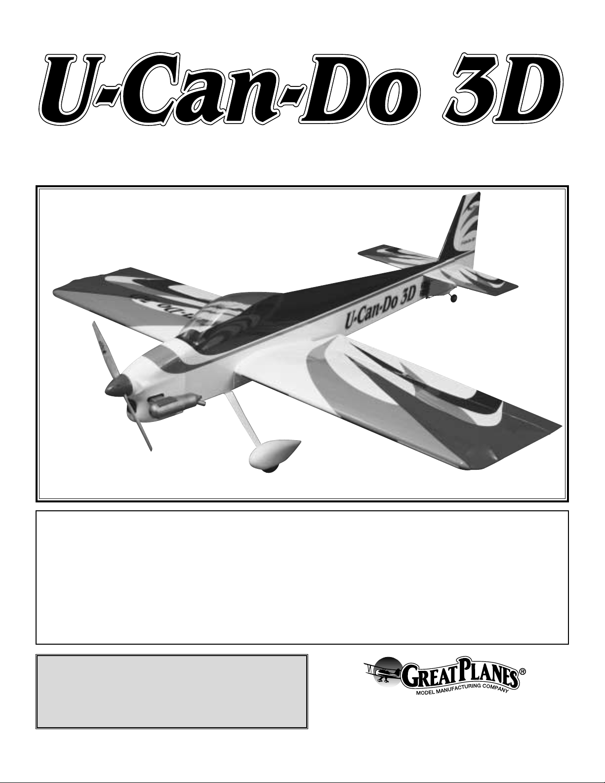
INSTRUCTION MANUAL
A. R. F.
Almost Ready to Fly
Wingspan: 65 in [1651mm]
Wing Area: 1072 sq in [69 dm2]
Weight: 7 lbs - 7 lbs 6 oz [3175 - 3345g]
Wing Loading: 15 - 15.9 oz/sq ft [46 - 48 g/dm2]
Length: 69.5 in [1765mm]
Engine: .61 - .91 cu in [10 - 15cc] two-stroke, .70 - .91 cu in [11 - 15cc] four-stroke
™
Page 2

INTRODUCTION................................................................2
SAFETY PRECAUTIONS..................................................2
DECISIONS YOU MUST MAKE ........................................3
Radio Equipment ................................................................3
Engine Recommendations.................................................3
ADDITIONAL ITEMS REQUIRED.....................................3
Hardware and Accessories................................................3
Covering Accessories.........................................................4
Adhesives and Building Supplies.......................................4
Optional Supplies and Tools...............................................4
IMPORTANT BUILDING NOTES.......................................4
KIT CONTENTS .................................................................5
ORDERING REPLACEMENT PARTS ...............................6
PREPARATIONS................................................................7
BUILD THE WING..............................................................7
Mount the Ailerons.............................................................7
Install the Aileron Servos and Pushrods............................8
Mount the Wing to the Fuselage......................................10
BUILD THE FUSELAGE..................................................11
Mount the Stab and Fin....................................................11
Mount the Wheel Pants & Landing Gear..........................13
Mount the Engine.............................................................15
Mount the Cowl................................................................15
Install the Tank .................................................................17
FINAL ASSEMBLY ..........................................................18
Install the Remaining Servos ...........................................18
Mount the Canopy ............................................................20
Apply the Decals..............................................................21
GET THE MODEL READY TO FLY..................................21
Check the Control Directions ...........................................21
Set the Control Throws.....................................................21
Balance the Model (C.G.).................................................21
Balance the Model Laterally.............................................22
PREFLIGHT.....................................................................22
Identify Your Model...........................................................22
Charge the Batteries........................................................22
Balance Propellers...........................................................23
Ground Check..................................................................23
Range Check....................................................................23
ENGINE SAFETY PRECAUTIONS.................................23
AMA SAFETY CODE ......................................................23
General.............................................................................23
Radio Control ...................................................................24
CHECKLIST.....................................................................24
FLYING.............................................................................24
Takeoff..............................................................................25
Flight.................................................................................25
Landing.............................................................................25
PERFORMANCE SETTINGS..........................................26
Whether you're just learning to do basic aerobatics or are
looking for a quick practice plane as a backup to your
$10,000 Unlimited aerobatic machine, U-CAN-DO 3D is just
the bird you're looking for.
Large control surfaces, light wing loading and an all around
performance design work together to put a fun-to-fly do-it-all
3D aerobatic machine in your hands. With the U-CAN-DO
3D on low rates, it is a perf ect choice f or learning to do basic
aerobatics or for great Sunday fun flying. With a powerful,
high torque 4-stroke such as an OS .91, the U-CAN-DO 3D
provides exceptional slow speed and below-stall-speed
(3D) aerobatic performance.
For the latest technical updates or manual corrections to the
U-CAN-DO 3D , visit the w eb site listed belo w and select the
Great Planes U-CAN-DO 3D ARF. If there is new technical
information or changes to this model, a “tech notice”box will
appear in the upper left corner of the page.
http://www.greatplanes.com/airplanes/index.html
1. Your U-CAN-DO 3D should not be considered a toy, but
rather a sophisticated, working model that functions very
much like a full-size airplane. Because of its performance
capabilities, the U-CAN-DO 3D 60, if not assembled and
operated correctly, could possibly cause injury to yourself or
spectators and damage to property.
2.Y ou must assemb le the model according to the instructions.
Do not alter or modify the model, as doing so may result in an
unsafe or unflyable model. In a few cases the instructions may
differ slightly from the photos. In those instances the written
instructions should be considered as correct.
3. You must take time to build straight, true and strong.
4. You must use an R/C radio system that is in first-class
condition and a correctly sized engine and components (fuel
tank, wheels, etc.) throughout the building process.
5. You must correctly install all R/C and other components so
that the model operates correctly on the ground and in the air .
6. You must check the operation of the model before every
flight to insure that all equipment is operating and that the
model has remained structurally sound. Be sure to check
clevises or other connectors often and replace them if they
show any signs of wear or fatigue.
PRO TECT YOUR MODEL,YOURSELF
& OTHERS...FOLLOW THESE
IMPORTANT SAFETY PRECAUTIONS
INTRODUCTIONTABLE OF CONTENTS
2
Page 3
7. If you are not already an experienced R/C pilot, you
should fly the model only with the help of a competent,
experienced R/C pilot.
8. WARNING: The cowl and wheel pants included in this kit
are made of fiberglass, the fibers of which may cause eye,
skin and respiratory tract irritation. Never blow into a part to
remove fiberglass dust, as the dust will blow back into your
eyes. Always wear safety goggles, a particle mask and
rubber gloves when grinding, drilling and sanding fiberglass
parts. Vacuum the parts and work area thoroughly after
working with fiberglass parts.
Remember:Take y our time and follow the instructions to
end up with a well-built model that is straight and true.
If you have not flown this type of model before, we
recommend that you get the assistance of an experienced
pilot in your R/C club for your first flights. If you're not a
member of a club, your local hobby shop has information
about clubs in your area whose membership includes
experienced pilots.
In addition to joining an R/C club, we strongly recommend y ou
join the AMA (Academy of Model Aeronautics). AMA
membership is required to fly at AMA sanctioned clubs.There
are over 2,500 AMA chartered clubs across the country.
Among other benefits, the AMA provides insurance to its
members who fly at sanctioned sites and events .Additionally,
training programs and instructors are available at AMA club
sites to help you get started the right way. Contact the AMA at
the address or toll-free phone number below:
Academy of Model Aeronautics
5151 East Memorial Drive
Muncie, IN 47302-9252
Tele. (800) 435-9262
Fax (765) 741-0057
Or via the Internet at:
http://www.modelaircraft.org
This is a partial list of items required to finish the U-CAN-DO
3D that may require planning or decision-making before
starting to build. Order numbers are provided in parentheses.
4+ channel radio with 6 standard-sized servos as noted below .
Note that a 6+ channel, fully computerized radio system is
highly recommended for maximum fle xibility and perf ormance.
Ailerons:
• Two ball bearing ser vos (50+ in oz: HCAM0170)
• One 20+" y-harness (HCAM2751)
OR
• Two 6" extensions (HCAM2701) and one y-harness
(HCAM2500)
Rudder:
• One high torque servo (90+ in oz: HCAM0191)
• One 24" servo extension (HCAM2200)
Elevator:
• Two ball bearing ser vos (50+ in oz:HCAM0170)
• If using a computerized radio two 24" servo extensions
(HCAM2200)
• If not using a computerized radio with Ailevator prog ramming,
then a servo reversing harness is required (FUTM4150)
Throttle:
• One servo, standard (HCAM0150)
.61 to .91 2-stroke, .70 to .91 4-stroke
Appropriate props, fuel, glow plugs, etc.for your engine.
Engine notes: The U-Can-Do 3D will hover on all of the
recommended engines.The engines on the lower end of the
range will hover nicely without over-speeding the airframe in
level flight.The engines on the higher end of the range will
hover and give the added power to recover from unwanted
attitudes, but throttle management needs to be used to keep
the speed down. Whatever engine you choose, a 6 pitch
prop or less is recommended.
In addition to the items listed in the “Decisions You Must
Make” section, following is the list of hardware and
accessories required to finish the U-CAN-DO 3D 60. Order
numbers are provided in parentheses.
❏ Hook & Loop Velcro (GPMQ4480)
❏ 3' Medium fuel tubing (GPMQ4131)
❏ Easy Fueler
™
fuel filling valve for glow fuel (GPMQ4160)
❏ Handy Mounts air valve, fuel filler mounts (GPMQ6000)
Hardware and Accessories
ADDITIONAL ITEMS REQUIRED
Engine Recommendations
Radio Equipment
DECISIONS YOU MUST MAKE
We, as the kit manufacturer, provide you with a top quality
kit and instructions, but ultimately the quality and
flyability of your finished model depends on how you build
it; therefore, we cannot in any way guarantee the
performance of your completed model and no
representations are expressed or implied as to the
performance or safety of your completed model.
3
Page 4
❏ 21st Centur y
®
sealing iron (COVR2700)
❏ 21st Centur y trim seal iron (COVR2750)
❏ 21st Centur y iron cover (COVR2702)
In addition to common household tools and hobby tools, this
is the “short list”of the most important items required to build
the U-CAN-DO 3D 60.
Great Planes Pro™CA and Epoxy
glue are recommended.
❏ 1/2 oz. Thin Pro CA (GPMR6001)
❏ 1/2 oz. Medium Pro CA+ (GPMR6007)
❏ 6-Minute Epoxy (GPMR6045)
❏ 30-Minute Epoxy (GPMR6047)
❏ Small T-pins (HCAR5100)
❏ Electric dr ill
❏ Drill bit set including (1/16" 3/32" 1/8" 5/64" and 1/2" bits)
❏ Small Phillips and flat blade screwdrivers (HCAR1040)
❏ Pliers with wire cutter (HCAR0630)
❏ Standard Hex wrench set (HCAR0520)
Here is a list of optional tools mentioned in the manual that
will help you build the U-CAN-DO 3D 60.
❏ Great Planes CG Machine
™
(GPMR2400)
❏ Top Flite
®
Precision Magnetic Prop Balancer™(TOPQ5700)
❏ Straightedge with scale (HCAR0475)
❏ Cutting mat (HCAR0456)
❏ Masking T ape (TOPR8018)
❏ CA Applicator Tips (GPMR6033)
❏ CA Debonder (GPMR6039)
❏ CA Accelerator (GPMR6034)
❏ Milled Fiberglass (GPMR6165)
❏ Microballoons (TOPR1090)
❏ R/C-56 Canopy Glue (JOZR5007)
❏ Epoxy Brushes (GPMR8060)
❏ Mixing Sticks (GPMR8055)
❏ Threadlocker (GPMR6060)
❏ Denatured Alcohol (for epoxy clean up)
❏ Hobby Knife (HCAR0105), #11 Blades (HCAR0211)
❏ Non-elastic monofilament or Kevlar fishing line (for stab
alignment)
❏ Builders Triangle Set (HCAR0480) (for fin alignment)
❏ Easy-Touch
™
Bar Sander (GPMR6170, or similar)
❏ Felt-Tip Marker (TOPQ2510)
❏ Small metal file
❏ Rotar y tool such as Dremel
®
❏ Rotar y tool reinforced cut-off wheel (GPMR8200)
❏ Curved Tip Canopy Scissors for trimming plastic parts
(HCAR0667)
❏ Dead Center
™
Engine Mount Hole Locator (GPMR8130)
❏ Great Planes AccuThrow
™
Deflection Gauge (for
measuring control throws, GPMR2405)
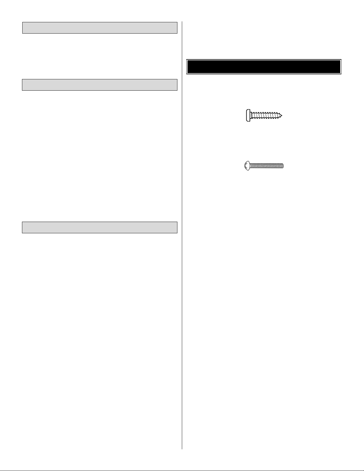
• There are two types of screws used in this kit:
Sheet metal screws are designated by a number and a
length. For example #6 x 3/4" [19mm]
This is a number six screw that is 3/4" [19mm] long.
Machine screws are designated by a number, threads per
inch and a length. For example 4-40 x 3/4" [19mm]
This is a number four screw that is 3/4" [19mm] long
with forty threads per inch.
• When you see the term
test fit
in the instructions, it
means that you should first position the part on the
assembly without using any glue, then slightly modify or
custom fit
the part as necessar y for the best fit.
• Whenever the term
glue
is written you should rely upon
your experience to decide what type of glue to use.When a
specific type of adhesive works best for that step, the
instructions will make a recommendation.
• Whenever just
epoxy
is specified you may use
either
30-
minute (or 45-minute) epoxy or6-minute epoxy.
• Photos and sketches are placed before the step they
refer to. Frequently you can study photos in following steps
to get another view of the same parts.
• The U-CAN-DO 3D is factory-covered with Top Flite
MonoKote®film. Should repairs ever be required, MonoKote
can be patched with additional MonoKote purchased
separately. MonoKote is packaged in six-foot rolls, but some
hobby shops also sell it by the foot. If only a small piece of
MonoKote is needed for a minor patch, perhaps a fellow
modeler would give you some. MonoKote is applied with a
model airplane covering iron, but in an emergency a regular
iron could be used. A roll of MonoKote includes full
instructions for application.Following are the colors used on
this model and order numbers for six foot rolls.
Jet White (TOPQ0204)
True Red (TOPQ0227)
Sky Blue (TOPQ0206)
Sapphire Blue (TOPQ0226)
Black (TOPQ0208)
IMPORTANT BUILDING NOTES
Optional Supplies and Tools
Adhesives and Building Supplies
Covering Accessories
4
Page 5
5
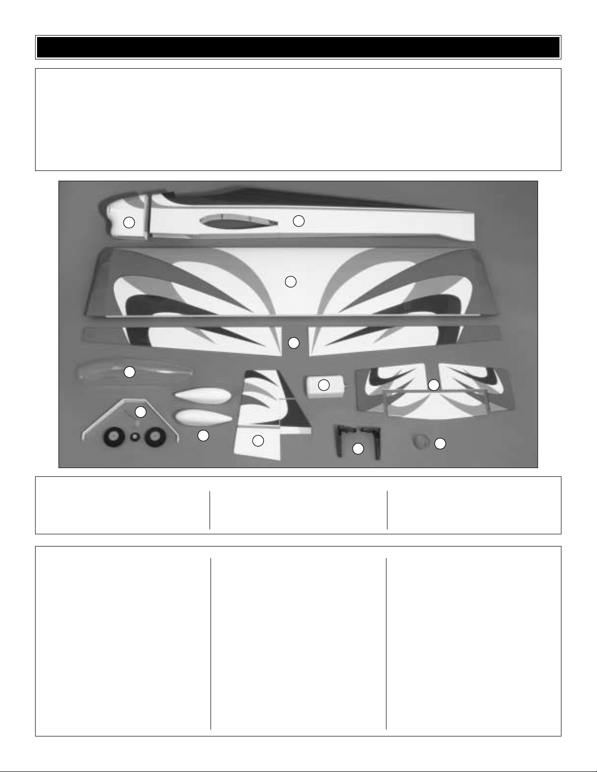
1 Fiberglass Cowl
2 Fuselage
3 Wing
4 Ailerons
5 Stab and Elevators
6 Fin and Rudder
7 Landing Gear
8 Canopy
9 Fuel Tank with Hardware
10 Adjustable Engine Mount
11 Spinner
12 Wheel Pants
(1) 17-1/2 .074 wire (throttle pushrod)
(2) 1/4 - 20 Blind Nuts (pre-installed in fuse)
(1) 11-3/4" Gray plastic outer pushrod tube
(throttle)
(5) 12" .074 wire threaded one end (ailerons)
(1) 2" x 9" hinge material
(6) Nylon clevis (rudder, elevator, ailerons,
throttle)
(5) Faslink (rudder, elevator, ailerons)
(2) Nylon 1/4 - 20 wing bolt (wing)
(5) Large nylon control horn (aileron,
rudder, elevator)
(7) Silicone clevis keepers (rudder, elevator,
ailerons, throttle)
(4) 6-32 x 3/4" socket head cap screw (main
gear and stab)
(4) #6 lock washers (main gear and stab)
(4) #6 flat washers (main gear and stab)
(4) 6-32 blind nuts (main gear and stab)
(14) #2 x 3/8" screws (cowl, canopy, wheel
pants)
(4) #2 washers (for mounting the cowl)
(4) 8-32 blind nuts (engine mount to firewall)
(4) 8-32 x 3/4" socket head screws (engine
to engine mount)
(4) 8-32 x 1" socket head screws (engine
mount to firewall)
(8) #8 flat washers (mounting engine and
engine mount)
(8) #8 lock washers (mounting engine and
engine mount)
(4) 5/32" wheel collar (main wheels)
(4) 6-32 x 1/8" socket head screw (main
wheels)
(6) 2-56 x 1/2" socket head screw (rudder,
elevator, ailerons)
(4) 2-56 x 3/4" socket head screw (aileron
control horns)
(1) Brass quick connect body (throttle
connection)
(1) Nylon retainer (Throttle connection)
(1) 4-40 x 1/4" SHCS (Throttle connection)
(1) 3/32 wheel collar (tail wheel)
(1) 4-40 set screw (tail wheel)
(2) Axles
(2) Nuts for the axles
Kit Contents (Photographed)
Kit Contents (Not Photographed)
Before starting to build, use the Kit Contents list to take an inventory of this kit to make sure it is complete and inspect
the parts to make sure they are of acceptable quality. If any parts are missing or are not of acceptable quality, or if you
need assistance with assembly, contact Great Planes Product Support. When reporting defective or missing parts, use
the part names exactly as they are written in the Kit Contents list on this page.
Great Planes Product Support:
Phone: (217) 398-8970
Fax: (217) 398-7721
E-mail: airsupport@greatplanes.com
KIT CONTENTS
1
8
7
12
6
2
3
4
9
10
5
11
Page 6

6
To order replacement par ts for the Great Planes U-CAN-DO 3D ARF, use the order numbers in the Replacement Parts
List that follows.Replacement parts are available only as listed. Not all parts are available separately (an aileron cannot
be purchased separately, but is only available with the wing kit). Replacement parts are not available from Product
Support, but can be purchased from hobby shops or mail order/Internet order firms. Hardware items (screws, nuts, bolts)
are also available from these outlets. If you need assistance locating a dealer to purchase parts, visit
www.greatplanes.com and click on “Where to Buy.” If this kit is missing parts, contact Product Support.
Replacement Parts List
Order Number Description Ho
w to Purchase
Missing pieces ................................................Contact Product Support
Instruction manual...........................................Contact Product Support
Full-size plans.................................................Not available
Kit parts listed below .......................................Hobby Supplier
GPMA2300 ...........Wing Kit (one piece wing, ailerons, dowels and hinge material)
GPMA2301 ...........Fuselage Kit (Fuse, belly pan, (2) balsa tank holders, stab fillet, (4) cowl
mounting blocks and servo tray)
GPMA2302 ...........Tail Set (stab, elevators, fin, rudder and hinge material)
GPMA2303 ...........Landing Gear
GPMA2304 ...........Fiberglass Cowl
GPMA2305 ...........Canopy
GPMA2306 ...........Wheel Pants (left and r ight wheel pant, (4) mounting plates)
GPMA2307 ...........Decal Sheet
GPMA2308 ...........Tailwheel Assembly (tail gear and tail wheel)
ORDERING REPLACEMENT PARTS
0" 1" 2" 3" 4" 5" 6" 7"
0 10 20 30 40 50 60 70 80 90 100 110 120 130 140 150 160 170 180
Inch Scale
Metric Scale
To convert inches to millimeters, multiply inches by 25.4
1/64" = .4mm
1/32" = .8mm
1/16" = 1.6mm
3/32" = 2.4mm
1/8" = 3.2mm
5/32" = 4mm
3/16" = 4.8mm
1/4" = 6.4mm
3/8" = 9.5mm
1/2" = 12.7mm
5/8" = 15.9mm
3/4" = 19mm
1" = 25.4mm
2" = 50.8mm
3" = 76.2mm
6" = 152.4mm
12" = 304.8mm
15" = 381mm
18" = 457.2mm
21" = 533.4mm
24" = 609.6mm
30" = 762mm
36" = 914.4mm
Metric Conversions
Page 7
❏ 1. If you have not yet done so already, remove the major
parts of the kit from the box (wings, fuse, wheel pants, cowl,
tail parts, etc.) and inspect them for damage.If any parts are
damaged or missing, contact Product Support at the address
or telephone number on page 5.
❏ 2. Remove the masking tape and separate the ailerons
from the wing, the rudder from the fin and the elevators from
the stab. Where necessary, use a covering iron with a
covering sock to tighten the covering that may have
loosened during storage or from removing the masking tape.
Apply pressure over sheeted areas and the servo openings
to thoroughly bond the covering to the wood.
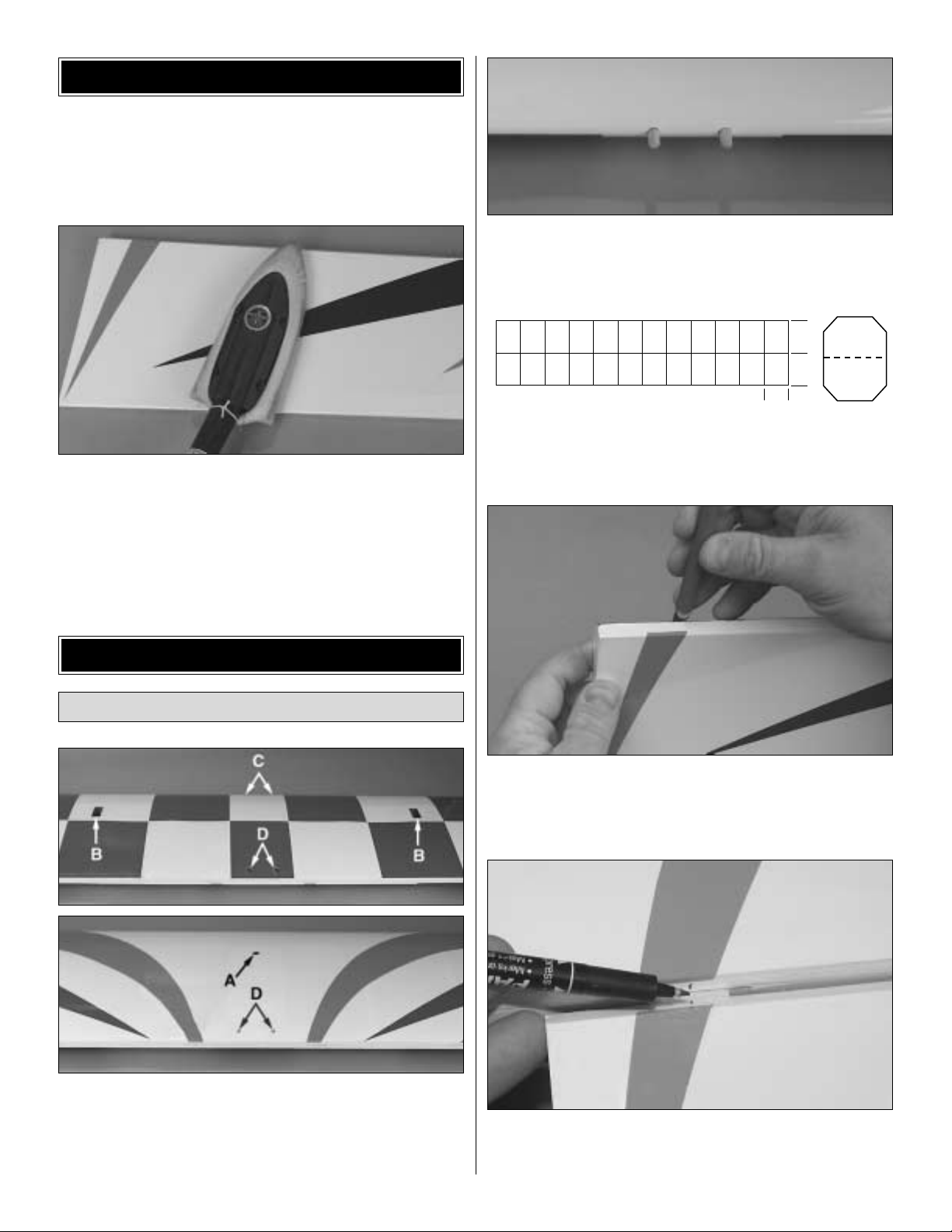
❏ 1. Trim the covering on the wing from
❏ A) The servo wire hole in the top center of the wing;
❏ B) Both servo openings;
❏ C) Both dowel holes;
❏ D) Top and Bottom wing-bolt holes.
❏2.Use your sanding bar to round one end of each of the 5/16"
x 1-3/4" [8 x 70mm] wing dowels.Use epoxy to glue the two wing
dowels into the wing, with the non-rounded end in the wing.
❏ 3. Cut eight 3/4" x 1" [19 x 25mm] hinges from the
2" x 9" [50 x 230mm] CA hinge strip.Snip the corners off so
they go in easier.
❏ 4. Test fit the hinges in the hinge slots of the aileron and
the wing. If you have difficulty inserting the hinges, insert a
#11 blade into the slot and carefully move it back and forth
to slightly widen the slot.
❏ 5. Test fit the ailerons to the wing with the hinges. Use a
fine-point ballpoint pen to mark the wing and ailerons at the
middle of each hinge.
1"
1"
3/4"
Mount the Ailerons
BUILD THE WING
PREPARATIONS
7
Page 8
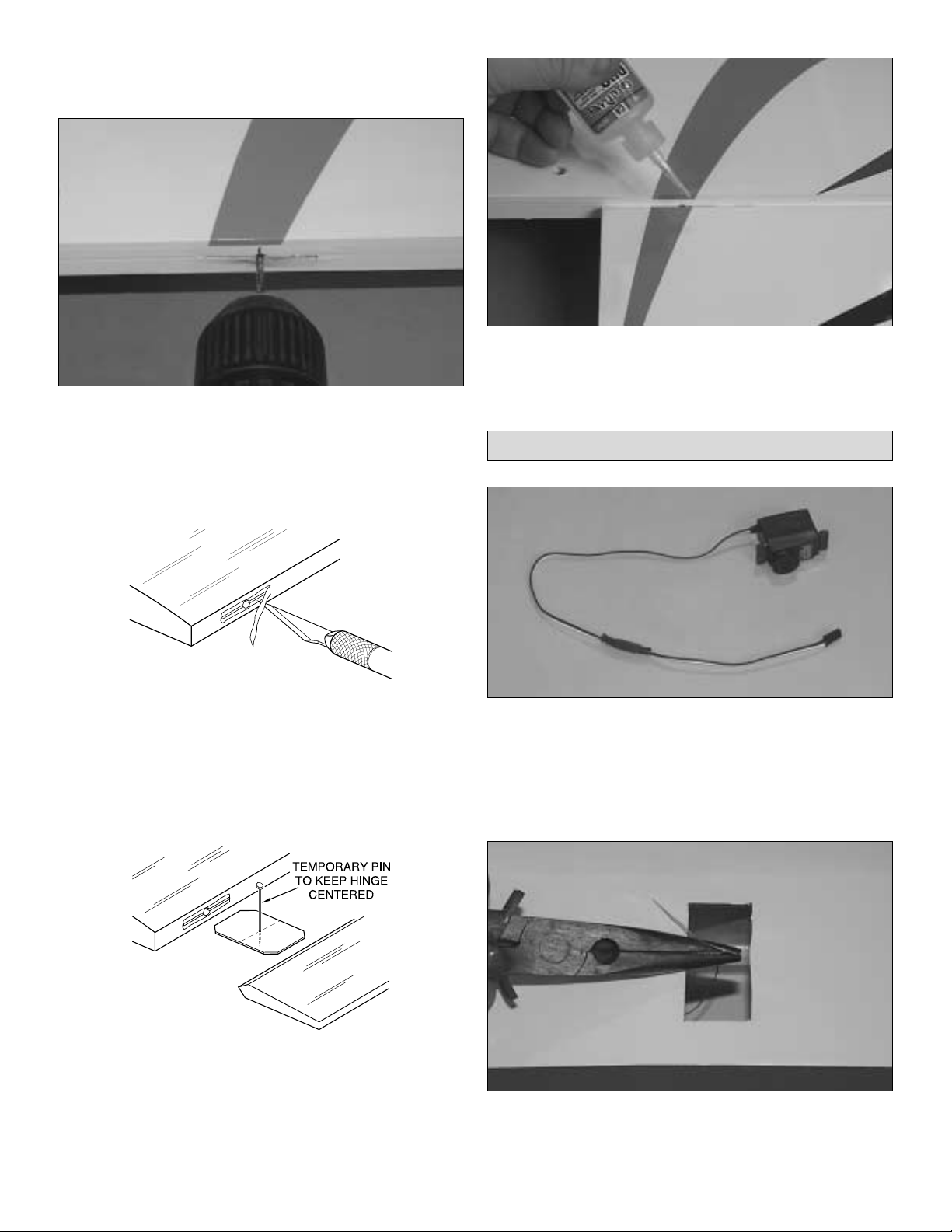
❏ 6. Separate the ailerons from the wing and take out all
the hinges.
❏ 7. Drill a 3/32" [2.4mm] hole, 1/2" [13mm] deep at the
marks you made in the center of each hinge slot.This space
will allow the CA to “wick”in. Follow with a #11 blade to clean
out the slots. Hint: If available, use a high-speed rotary tool
to drill the holes.
❏ 8. Cut a small strip of covering from both sides of each
hinge slot. If this is not done the covering may interfere with
the penetration of the CA into the slot and may also interf ere
with the free movement of the aileron.
❏ 9. Stick a pin through the center of each hinge. Fit the
ailerons to the wing with the hinges. The pin will keep the
hinge centered.Remove the pins from the hinges.Adjust the
ailerons so there is a small gap–just enough to see light
through or to slip a piece of paper through–between the
aileron and the wing.
❏ 10. Apply six drops of thin CA to the top and bottom of
each hinge. Do not use CA accelerator. After the CA has
fully hardened, test the hinges by pulling on the ailerons.
❏ 1. Add servo extensions to the two aileron servos , so that
the total length of the leads will be at least 18" [460mm] from
the servo to the end of the extension. Using tape or heat
shrink tubing, securely attach the servo extension to the
servo. Note: If you are using Futaba®servos, a 6" [150mm]
lead is perfect.
❏❏2. Using needle nose pliers, pull the string out of the
right wing's servo hole.Tie the string to the end of the servo
lead. Note: Take care not to pull the string loose from the
other side of the wing.
Install the Aileron Servos and Pushrods
AWAY FROM THE SLOT
CUT THE COVERING
8
Page 9
❏❏3. Pull the center of the str ing out of the servo hole in
the wing. It might take a little fishing to get it out. Take your
time. Use the string to pull the servo wire through the wing,
being careful to not pull the string loose from the other end
taped in the wing. Fit the servo in the wing.
❏❏4. Drill 1/16" [1.6mm] holes through the servo mount
for the servo screws.Add a few drops of thin CA to the holes
and allow to fully harden. Mount the aileron servo using the
hardware that came with the servo.
❏❏5. Make a mark on the bottom L.E. of the right aileron
12-1/2" [315mm] from the inboard end of the aileron.
❏❏6. Center a control horn on the mar k you made. Drill
two 1/16" [1.6mm] holes through the aileron for mounting the
control horn. Mount the control horn using the 2-56 x 3/4"
[19mm] socket head cap screws (SHCS) with the nylon
backing plate on the top-side of the aileron. Note: Tur ning a
2-56 tap through the back plate holes makes it easier to get
the SHCS to thread into them.
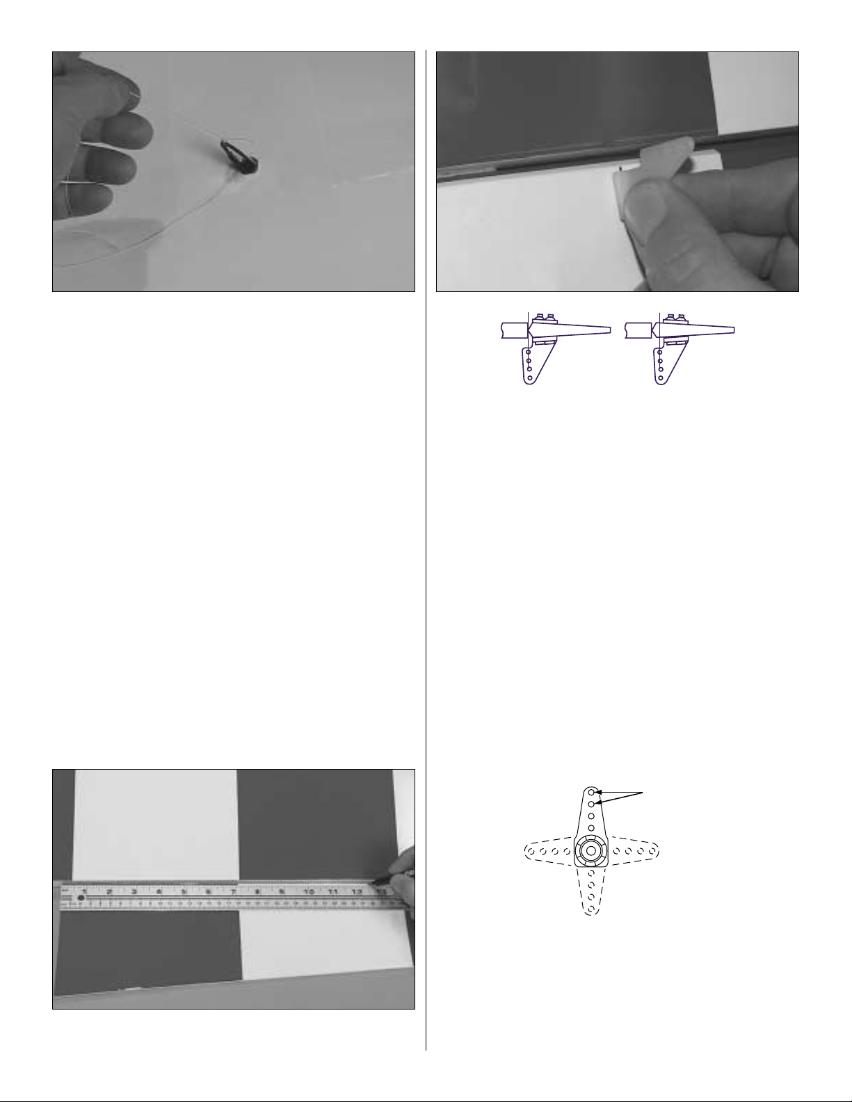
❏❏7. Thread a clevis 25 turns onto the end of one 12"
[305mm] pushrod. Slip a silicone retainer over the pushrod
down to the clevis.
❏❏8. Make a one-arm ser vo arm by cutting three arms
off a four-arm servo arm. Enlarge the holes in the ar m with
a Hobbico®Servo Horn Drill (or a #48 or 5/64" [2mm] drill bit)
so the pushrod will fit. Connect the servo lead to the
receiver. Tur n on the transmitter and receiver to center the
servo. Place the servo arm on the servo so it is pointing
straight towards the wing tip.
Correct Incorrect
9
Enlarge to 5/64"
Cut Off
Unused Arms
Page 10

❏❏9.Attach the clevis with pushrod to the outer hole of the
control horn. Hold the aileron straight with the wing and mark
the pushrod where it crosses the servo arm.Bend the pushrod
90 degrees away from the wing on the mark you made.
❏❏10. Attach the pushrod to the control horn as shown
in the sketch.Cut off the excess pushrod.Be certain to leave
1/16" [1.6mm] of wire protruding from the Faslink as shown
in the sketch.
❏ 11. Repeat steps 2-10 for the other left side of the wing.
❏ 12. Slide a silicone retainer over the two servo wires so
they won’t fall back into the wing.
❏ 1. Mount the wing to the fuse with the two 1/4-20 x 2"
[51mm] nylon bolts.
❏ 2.Trim the two bolt holes in the belly pan.Using 6-minute
epoxy, glue the belly pan to the wing, being careful to not
glue the belly pan or wing to the fuse.Tape the belly pan to
the wing until the epoxy has cured.
❏ 3. Remove the two 1/4-20 x 2" [51mm] nylon bolts.
Remove the wing. Note: The wing might press out of the
fuse a little hard the first few times.
Mount the Wing to the Fuselage
10
1/16"
Servo Arm Pushrod Wire
Faslink
Page 11

❏ 1. Attach the elevators to the stab with the same hinging
technique used for the ailerons.
❏ 2. Using a 7/64" hex wrench, remove the two 6-32 x 3/4"
[19mm] socket head cap screws from the stab fillet.
❏ 3. Use a #11 blade to cut between the false stab and the
stab fillet. Note: The false stab is used in building the fuse. It
can also be used for transport to keep the stab fillet in place.
❏ 4. Use a #11 blade to remove the false fin from the fin
slot.Note: It may be necessary to pry up slightly on the front
of the fin fillet to remove it.
❏ 5. Fit the fin in place and mark the covering on the fin
where it contacts the fuse.
❏ 6.Trim the covering 1/8" [3mm] below the lines y ou made
on the fin. Be very careful not to cut into the fin itself. Wipe
away the marks on the fin you made in the previous step.
The epoxy used in the next step will make removing those
lines difficult.
Mount the Stab and Fin
BUILD THE FUSELAGE
11
Page 12

How to cut covering from balsa.
To avoid cutting into the balsa, use a soldering iron instead
of a hobby knife to cut the covering.The tip of the soldering
iron doesn't have to be sharp, but a fine tip does work best.
Allow the iron to heat fully. Use a straightedge to guide the
soldering iron at a rate that will just melt the covering and not
burn into the wood. The hotter the soldering iron, the faster
it must move to melt a fine cut.
❏ 7. Apply 6-minute epoxy to all joining surf aces of the fin.Fit
the fin in place, aligning the TE of the fin with the TE of the fuse .
❏ 8.Test fit the nylon tail gear bearing with the tail gear wire
into the slot in the rear of the fuse.
❏9.Use a hobby knife or a 5/32" [4mm] brass tube sharpened
on the end to cut a groove in the leading edge of the rudder to
accommodate the nylon tail gear bearing. Drill a 1/8" [3.2mm]
hole into the rudder for the “arm” portion of the tail gear wire.
❏ 10. Carefully apply a small dab of petroleum jelly to the
top and bottom of the tail gear bearing where the tail gear
wire goes through the bearing to keep glue from entering.
Apply 30-minute epoxy inside the slot in the fuselage for the
tail gear bearing and to the hinge of the tail gear bearing.
Install the tail gear bearing and wipe away any excess epoxy .
❏ 11.T est fit the rudder to the tail gear and the fin using three
CA hinges. Repeat until you are satisfied that the rudder fits
properly .Apply epoxy in the rudder for the tail gear wire.Fit the
rudder with hinges to the fuse and wipe away residual epoxy.
Apply 6 drops of thin CA to both sides of each hinge.
12
Page 13

❏ 12. Trim the two bolt holes in the stab covering. Bolt the
stab and stab fillet in place, using the two 6-32 x 3/4" [19mm]
SHCS.NOTE:If you don’t plan on removing the stab,glue
the bolts in with medium CA. If you do plan on removing
it, make sure to check the tightness of the screws often.
❏ 13. Attach the 1-1/4" [32mm] tail wheel with the 3/32"
wheel collar and the 4-40 set screw.
❏ 1. Glue one 3/32" x 1-1/8" x 1-1/8" [2.4 x 28 x 28mm]
plywood wheel pant mount with a 3/16" [4.8mm] hole to a
3/32" x 1-1/8" x 1-1/8" [2.4 x 28 x 28mm] plywood wheel
pant mount with a 1/2" [13mm] hole.Make two sets of these.
❏❏2. Make a mark on the right wheel pant centered
between the wheel pant supports and 1/2" [13mm] up from
the bottom edge.Use a high-speed rotary tool with a cutting
bit or a hobby knife to cut a 1/2" [13mm] hole centered on
the mark.
❏❏3.Round the bottom edge of the wheel pant mount so
it fits in the pant when the 1/2" [13mm] hole in the mount is
centered over the hole in the pant. Glue the mount to the
pant with 30-minute epoxy. The inside of the wheel pant
mount has the 1/2" [13mm] hole. Hint: for the most secure
bond, add microballoons (TOPR1090) or milled glass fibers
(GPMR6165) to the epoxy.
❏❏4. Use a metal saw or a high-speed rotary tool with a
reinforced cut-off wheel to cut 5/16" [8mm] from one of the
bolt-on axles.Mount the axle to the landing gear with the nut.
Mount the Wheel Pants & Landing Gear
13
Page 14

❏❏5. Drill 3/32" [2.4mm] holes through the landing gear
diagonally on both sides of the axle nut.
❏❏6. Temporarily slide the wheel pant, a wheel collar,
wheel and second wheel collar onto the axle.Determine where
the set screws for the wheel collars will be positioned on the
axle. Remove the wheel and pant, and then file flat spots on
the bottom of the axle for the set screws in the wheel collars.
❏❏7.Mount the wheel to the axle and tighten the set screws.
❏❏8.Drill two 1/16" [1.6mm] holes through the pant using
the holes in the gear as a guide.
❏❏9.Fasten the wheel pants to the landing gear with two
#2 x 3/8" screws. Remove the set screws in the wheel
collars and add a drop of oil to the axle and the wheel. Add
a drop of threadlocker to the set screws , install them into the
wheel collars and securely tighten. Note: Double check that
the wheel spins freely.
❏ 10.Return to step 2 and mount the other wheel and pant
to the left landing gear the same way.
❏ 11. Mount the landing gear to the fuse with two 6-32 x 3/4"
SHCS, #6 flat washers and #6 lock washers.
14
Page 15

❏ 1. Draw a vertical line on the firewall using the embossed
lines as a guide.Note: This line is offset to the left side of the
fuse so that the spinner will be on the center-line of the fuse.
❏ 2. Trim the spreader bars from both halves of the engine
mount. Mount the engine mount to the firewall with four
8-32 x 1" [25mm] SHCS, #8 flat washers and #8 lock w ashers,
but do not fully tighten the bolts.
❏ 3. Adjust the width of the mount to fit the engine. Center
the molded-in “tick” mar ks on the engine mount equally to
the left and right of the vertical line on the firewall. Tighten
the mounting bolts.
❏ 4. Place the back plate of the spinner on the engine.
Note: Depending on your engine choice, it may be
necessary to enlarge the hole in the back plate.
❏ 5. Use small clamps or another method to temporarily
secure the engine to the mount with the back plate of the
spinner 5-7/8" [150mm] from the firewall. Use the Great
Planes Dead Center™Engine Mount Hole Locator
(GPMR8130) or your preferred method to mark the engine
mount holes onto the engine mount.
❏ 6. Remove the engine from the mount. Drill #29 holes
through the mount at the marks you made. Tap 8-32 threads
into the mount. Mount the engine to the mount with four
8-32 x 3/4" [19mm] SHCS, #8 flat washers and #8 lock w ashers.
❏ 1. Use epoxy to glue the four 3/8" x 3/4" x 3/4"
[9.5 x 19 x 19mm] maple cowl mounting blocks to the fire wall
in approximately the locations shown.
Mount the Cowl
Mount the Engine
15
Page 16

❏ 2. Hold a ruler to the fuse centered on one of the cowl
mounting blocks. Use a felt-tip pen to draw a line directly
onto the fuse along the straightedge.
❏ 3. Mark a reference point on the end of the line exactly
6" [152mm] from the center of the cowl mounting block.
❏ 4.Mark the location of the remaining three cowl mounting
blocks the same way.
❏ 5.Place the cowl on the fuse.Mount the spinner and prop
to the engine. Position the cowl on the fuse so it is in
alignment with the spinner. Be certain there is at least a
3/32" [2.5mm] gap between the front of the cowl and the
back plate of the spinner. It may be helpful to have an
assistant hold the cowl for you.
❏ 6. Align the ruler with the line on the fuselage. Mark the
center of the cowl mounting block on the cowl 6" from the
reference point. Dr ill a 1/16" [1.6mm] hole through the cowl
and the mounting block at the mark. Enlarge the hole in the
cowl only with a 3/32" [2.4mm] drill. Mount the cowl to the
block with a #2 x 3/8" [9.5mm] screw and a #2 washer
❏ 7. With your assistant holding the cowl in position, mark,
drill and mount the cowl to the three remaining cowl
mounting blocks the same way
❏8.Remove the cowl.Clean the reference marks off the fuse.
9.Use the filler valve mount from a Great Planes Handy Mounts
set (GPMQ6000), or fashion a mount from 1/8" [3mm] plywood
(not included) for the fuel filler valve. A Great Planes EasyFueler for glow fuel was used on this model (GPMQ4160, not
included with this kit).Use epoxy to securely glue the filler valve
mount to the firewall in a location where the filler valve will be
accessible outside the cowl when it's time to fuel the engine.
❏ 10. Use thin cardboard or plastic to make templates for
the muffler, mixture screw, filler valve and glow plug cutouts
in the cowl.Tape the template(s) to the fuselage accurately
indicating the positions. Note: With this engine installation
we installed the muffler bolts through two 1/4" [6mm] holes
in the right side of the cowl. This is the time to decide how
you are going to mount your muffler.
❏ 11. Remount the cowl under the templates. Use a felt-tip
pen to transfer the holes in the template onto the cowl.
Remove the templates and the cowl.
16
Page 17

❏ 12. Cut out the holes in the cowl with a high-speed rotary
tool and a small cutting bit.
❏ 13. Cut the air opening in the front of the cowl as shown.
Note: Do not remount the cowl. The tank, fuel line and
throttle pushrod still need to be installed.
❏ 1. Roughen the outside of the 11-3/4" [300mm] gray
pushrod outer tube with coarse sand paper. Fit the tube
through the firewall and the second former leaving 1/8"
[3mm] protruding from the firewall. Glue the tube to the
firewall and the second former in the fuse with thin CA.
❏ 2. Arrange the stopper and tubes as shown in the photo,
then insert them into the tank. Tighten the screw to expand
the stopper, thus sealing the tank. Be cer tain the fuel line
weight (clunk) at the end of the fuel line inside the tank does
not contact the rear of the tank. Otherwise, the line may
become stuck above the fuel level and discontinue fuel flow.
Remember (or use a felt-tip pen to mark) which tube is the
fuel pick-up tube and which tube is the vent (that will be
connected to the pressure fitting on the engine’s muffler).
❏ 3. Install the tank in the fuse. Fit the neck through the
hole in the firewall. Be certain the vent tube inside the tank
is pointing upward.
❏ 4. Glue a 5/16" x 3/4" x 3" [8 x 19 x 80mm] balsa block
to the fuse to hold the tank in place.
Install the Tank
17
Balsa Fuel Tank Support
Page 18

❏ 1. Add servo extensions to the three tail servos so that
the total length of each lead will be at least 36" (914mm)
from the servo to the end of the extension. Using tape or
heat shrink tubing, securely attach the servo extension to
the servo. Note: Use 24" [600mm] extensions with Futaba
servos to get the 36" [914mm] length.
❏ 2.Trim the covering from the three tail servo holes.Fit the
servos in place. Note: The ser vo leads need to go forward
in the fuse to the wing opening.
❏ 3. Drill 1/16" [1.6mm] holes through the servo mount for
the servo screws. Add a few drops of thin CA to the holes
and allow to fully harden. Mount the tail servos using the
hardware that came with the servo.
❏ 4. Make a mark on the bottom L.E. of each elevator 1/2"
[13mm] from the inboard edge of each elevator. Position the
control horn centered over the mark.Mark the hole locations
on the elevator.
❏ 5. Drill 1/16" [1.6mm] holes through the elevators for
mounting the control horns with 2-56 x 1/2" SHCS [socket head
cap screws], then mount the control horn using the screws and
the nylon backing plate on the top-side of the elevators. Note:
Turning a 2-56 tap through the back plate holes makes it easier
to get the socket head cap screws to thread into them.
❏ 6. Mount the rudder control horn the same as the
elevators’, positioning it so that it captures the tail gear wire
in the rudder.
Correct Incorrect
Install the Remaining Servos
FINAL ASSEMBLY
18
Page 19

❏7.Thread a clevis 25 turns onto one end of each of the three
12" [305mm] pushrods.Slip a silicone retainer over the clevises .
❏ 8. Make three one-arm ser vo arms. Enlarge the holes in
the arm with a Hobbico Servo Horn Drill (or a #48 or 5/64"
(2mm) drill bit) so the pushrod will fit.
Use these photos for the next three steps. NOTE: The
photos depict a radio setup that does not have mixing. If
your radio has twin elevator mixing, mount both servo arms
towards the stab.
❏ 9. Connect the ser vo leads to the receiver. Tur n on the
transmitter and receiver to center the servos. Attach the
servo arms to the servos 90 degrees to the servo.
❏ 10.Attach the clevises with pushrods to the control horns.
Hold the control surfaces straight and mark the pushrods
where they cross the servo arms. Bend the pushrods 90
degrees away from the fuse on the marks you made. Turn
the receiver and transmitter off.
❏ 11. Attach the pushrods to the control horns as shown.
Trim the pushrod, being cer tain to leave 1/16" [1.6mm] of
wire protruding from the Faslinks.
❏ 12. Screw a clevis 10 turns onto the end of the 17-1/2"
[445mm] throttle pushrod. Bend the pushrod as necessary
for a smooth action.
❏ 13. Glue the servo tray in place with medium CA, as
shown in the photo. Fit the throttle servo in the tray but do
not screw it in place at this time.
❏ 14. Connect the throttle pushrod to the throttle servo with
the screw-lock connector.
❏ 15. Let the pushrod locate the servo in the tray. Mount
the servo to the servo tray with the hardware provided with
your servo.
19
Page 20

❏ 16. Route the fuel lines as needed and mount the cowl,
prop, muffler and spinner.
❏ 17. Wrap the batter y pack and receiver in at least 1/4"
[6mm] of R/C foam rubber and install them in the fuselage.
On our model with the O.S. MAX .61 FX, the batter y and
receiver were mounted where shown in the photo to
minimize the amount of tail weight required to balance the
model at the correct C.G.Securely hold the battery pack and
receiver in position with the 5/16" x 3/4" x 3" [8 x 19 x 80mm]
balsa block glued between the fuse sides. Simply stuffing
the receiver and battery pack in place with additional foam
rubber is not a secure method of holding them in place.
❏ 18. Mount the receiver on/off switch. A Great Planes
Switch & Charge Jack Mounting Set (GPMM1000), not
included, was used on this model. Be certain it is in a
location away from the engine exhaust.
❏ 19. Extend the receiver antenna and guide it out of the
fuselage. Connect it to a pin pressed into the bottom of the
fuse. Be certain there is a strain relief on the antenna to
keep stress off the solder joint inside the receiver. On our
prototype we drilled a 3/32" [2.4mm] hole through the
bottom sheeting aft of the wing opening and routed the
antenna through the hole. The end of the antenna was
connected to a hook made from a cut-off servo arm
connected to a small rubber band and the tail gear.
❏1.Use curved-tip scissors to cut out the canopy along the cut
line.True the edges by sanding with medium-grit sandpaper.
❏ 2. Place the canopy on the cockpit.Use a fine-point felt-tip
pen to lightly trace the outline of the canopy onto the fuse.
Option: Four #2 x 3/8" [9.5mm] screws are provided if you
prefer to make the canopy removable.
❏ 3. Remove the canopy. Use a pin to poke several holes
through the covering all the way around the cockpit 3/32"
[2.4mm] inside the line you marked. These holes will help
the glue adhere to the cockpit when it's time to glue the
canopy on. Use a tissue dampened with alcohol to wipe
away the ink line.
❏ 4. Wash the canopy in warm, soapy water. Glue the
canopy to the fuse with R/C-56 Canopy Glue (JOZR5007).
CA could be used, but great care must be taken not to f og the
canopy or use too much CA which could run onto the canopy
or the covering. Canopy glue provides working time and can
be wiped away with a damp tissue before it dries.Use rubber
bands, weights, tape or whate v er method appropriate to hold
the canopy to the cockpit until the glue dries.
Mount the Canopy
20
Page 21

1.Use scissors or a sharp hobby knife to cut the decals from
the sheet.
2. Be certain the model is clean and free from oily
fingerprints and dust. Prepare a dishpan or small bucket with
a mixture of liquid dish soap and warm water–about one
teaspoon of soap per gallon of water.Submerse the decal in
the soap and water and peel off the paper backing. Note:
Even though the decals hav e a “sticky-back” and are not the
water transfer type , submersing them in soap & water allo ws
accurate positioning and reduces air bubbles underneath.
3. Position decal on the model where desired. Holding the
decal down, use a paper towel to wipe most of the water a way.
4. Use a piece of soft balsa or something similar to
squeegee remaining water from under the decal. Apply the
rest of the decals the same way.
❏ 1. Turn on the transmitter and receiver and center the
trims. If necessary, remove the servo arms from the servos
and reposition them so they are centered. Reinstall the
screws that hold on the servo arms.
❏ 2. With the transmitter and receiver still on, check all the
control surfaces to see if they are centered.If necessary, adjust
the clevises on the pushrods to center the control surfaces.
❏ 3. Make certain that the control surfaces and the
carburetor respond in the correct direction as shown in the
diagram.If any of the controls respond in the wrong direction,
use the servo reversing in the transmitter to reverse the
servos connected to those controls. Be cer tain the control
surfaces have remained centered. Adjust if necessary.
Use a ruler to accurately measure and set the control throw of
each control surface as indicated in the chart that follows.If your
radio does not have dual rates, we recommend setting the
throws at the low rate settings.NOTE:The throws are measured
at the widest part of the elevators, rudder and ailerons.
More than any other factor, the C.G. (balance point) can
have the greatest effect on how a model flies and may
determine whether or not your first flight will be successful.
If you value this model and wish to enjoy it for many flights,
DO NOT OVERLOOK THIS IMPORTANT PROCEDURE.
A model that is not properly balanced will be unstable and
possibly unflyable.
Balance the Model (C.G.)
IMPORTANT: The U-CAN-DO 3D has been extensively
flown and tested to arrive at the throws at which it flies best.
Flying your model at these throws will provide you with the
greatest chance for successful first flights.If, after you have
become accustomed to the way the U-CAN-DO 3D flies, y ou
would like to change the throws to suit your taste , that is fine.
However, too much control throw could make the model
difficult to control, so remember, “more is not always better.”
We recommend the following control surface throws:
High Rate Low Rate
ELEVATOR: 1-1/8" [28mm] up 3/4" [19mm] up
1-1/8" [28mm] down 3/4" [19mm] down
RUDDER: 2-1/4" [57mm] right 1-1/4" [31mm] right
2-1/4" [57mm] left 1-1/4" [31mm] left
AILERONS: 1-3/8" [35mm] up 7/8" [22mm] up
1-3/8" [35mm] down 7/8" [22mm] down
3D Control Throws
NOTE: The 3D control throws are only meant to be used
for extreme aerobatics. These are not meant for normal
flying. Be confident using your dual rate switches before
utilizing these rates.
ELEVATOR: 3" [75mm] up
3" [75mm] down
RUDDER: 4" [100mm] right
4" [100mm] left
AILERONS: 2-1/8" [55mm] up
2-1/8" [55mm] down
Set the Control Throws
Check the Control Directions
GET THE MODEL READY TO FLY
Apply the Decals
21
4-CHANNEL RADIO SETUP
(STANDARD MODE 2)
4-CHANNEL
TRANSMITTER
ELEVATOR MOVES UP
4-CHANNEL
TRANSMITTER
RIGHT AILERON MOVES UP
LEFT AILERON MOVES DOWN
RUDDER MOVES RIGHT
CARBURETOR WIDE OPEN
4-CHANNEL
TRANSMITTER
4-CHANNEL
TRANSMITTER
Page 22

At this stage the model should be in ready-to-fly condition
with all of the systems in place including the engine, landing
gear, covering and the radio system.
❏ 1. Use a felt-tip pen or 1/8"-wide tape to accurately mark
the C.G. on the top of the wing. The C.G. is located 4-7/8"
[124mm] back from the leading edge of the wing.
❏ 2.With the wing attached to the fuselage, all parts of the
model installed (ready to fly) and an empty fuel tank, place
the model upside-down on a Great Planes CG Machine, or
lift it upside-down at the balance point you marked.
❏ 3. If the tail drops, the model is “tail heavy” and the
battery pack and/or receiver must be shifted forward or
weight must be added to the nose to balance. If the nose
drops, the model is “nose heavy” and the battery pack
and/or receiver must be shifted aft or weight must be added
to the tail to balance. If possible, relocate the battery pack
and receiver to minimize or eliminate any additional ballast
required. If additional weight is required, nose weight may
be easily added by using a “spinner weight”(GPMQ4645 for
the 1 oz. weight, or GPMQ4646 for the 2 oz. weight). If
spinner weight is not practical or is not enough, use Great
Planes (GPMQ4485) “stick-on” lead. A good place to add
stick-on nose weight is to the firewall (don't attach weight to
the cowl–it is not intended to support weight). Begin by
placing incrementally increasing amounts of weight on the
bottom of the fuse over the firew all until the model balances .
Once you have determined the amount of weight required, it
can be permanently attached. If required, tail weight may be
added by cutting open the bottom of the fuse and gluing it
permanently inside.
Note: Do not rely upon the adhesive on the back of the lead
weight to permanently hold it in place. Over time, fuel and
exhaust residue may soften the adhesive and cause the
weight to fall off .Use #2 sheet metal screws, RTV silicone or
epoxy to permanently hold the weight in place.
❏ 4. IMPORTANT: If you found it necessary to add any
weight, recheck the C.G.after the weight has been installed.
❏ 1. With the wing level, have an assistant help you lift the
model by the engine propeller shaft and the bottom of the
fuse under the TE of the fin.Do this several times.
❏2.If one wing always drops when you lift the model, it means
that side is heavy. Balance the airplane by adding weight to the
other wing tip. An airplane that has been laterally balanced
will track better in loops and other maneuvers.
No matter if you fly at an AMA sanctioned R/C club site or if
you fly somewhere on your own, you should always have
your name, address, telephone number and AMA number
on or inside your model. It is required at all AMA R/C club
flying sites and AMA sanctioned flying events. Fill out the
identification tag on the decal sheet and place it on or inside
your model.
Follow the battery charging instructions that came with your
radio control system to charge the batteries. You should
always charge your transmitter and receiver batteries the
night before you go flying and at other times as
recommended by the radio manufacturer.
NOTE: Checking the condition of your receiver battery pack
is highly recommended. All battery packs, whether it's a
trusty pack you've just taken out of another model, or a new
battery pack you just purchased, should be cycled, noting
the discharge capacity. Oftentimes, a weak battery pack can
be identified (and a valuable model saved!) by comparing its
actual capacity to its rated capacity. Refer to the instructions
and recommendations that come with your cycler. If you
don't own a battery cycler, perhaps you can have a friend
cycle your pack and note the capacity for you.
Charge the Batteries
Identify Y our Model
PREFLIGHT
Balance the Model Laterally
This is where your model should balance for your first
flights. Later, you may wish to experiment by shifting the
C.G. up to 3/8" [9mm] forward or 1/2" [13mm] back to
change the flying characteristics. Moving the C.G. forward
may improv e the smoothness and stability, but it may then
require more speed for takeoff and make it more difficult
to slow for landing. Moving the C.G. aft makes the model
more maneuverable, but could also cause it to become
too difficult for you to control. In any case, start at the
location we recommend and do not at any time balance
your model outside the recommended range.
22
Plane is balanced correctly when
the bottom of the fuse is horizontal.
4-7/8"
[124mm]
Page 23

Carefully balance your propeller and spare propellers before
you fly. An unbalanced prop can be the single most
significant cause of vibration that can damage your model.
Not only will engine mounting screws and bolts loosen,
possibly with disastrous effect, but vibration may also
damage your radio receiver and battery. Vibration can also
cause your fuel to foam, which will, in turn, cause your
engine to run hot or quit.
We use a Top Flite®Precision Magnetic Prop Balancer
™
(TOPQ5700) in the workshop and keep a Great Planes
Fingertip Prop Balancer (GPMQ5000) in our flight box.
If the engine is new, follow the engine manufacturer's
instructions to break-in the engine. After break-in,
confirm that the engine idles reliably, transitions smoothly
and rapidly to full power and maintains full powerindefinitely. After you run the engine on the model, inspect
the model closely to make sure all screws remained tight,
the hinges are secure, the prop is secure and all pushrods
and connectors are secure.
Ground check the operational range of your r adio before the
first flight of the day. With the transmitter antenna collapsed
and the receiver and transmitter on, you should be able to
walk at least 100 feet away from the model and still have
control. Have an assistant stand by your model and, while
you work the controls, tell you what the control surfaces are
doing. Repeat this test with the engine running at various
speeds with an assistant holding the model, using hand
signals to show you what is happening. If the control
surfaces do not respond correctly, do not fly! Find and
correct the problem first.Look for loose servo connections or
broken wires, corroded wires on old servo connectors, poor
solder joints in your battery pack or a defective cell, or a
damaged receiver crystal from a previous crash.
Keep all engine fuel in a safe place, away from high heat,
sparks or flames, as fuel is very flammable. Do not smoke
near the engine or fuel; and remember that engine exhaust
gives off a great deal of deadly carbon monoxide.Therefore
do not run the engine in a closed room or garage.
Get help from an experienced pilot when learning to
operate engines.
Use safety glasses when starting or running engines.
Do not run the engine in an area of loose gravel or sand;the
propeller may throw such material in your face or eyes.
Keep your f ace and body as well as all spectators a wa y from the
plane of rotation of the propeller as you start and run the engine.
Keep these items away from the prop: loose clothing, shir t
sleeves, ties, scarfs, long hair or loose objects such as
pencils or screwdrivers that may fall out of shirt or jacket
pockets into the prop.
Use a “chicken stick” or electric starter to star t the engine.
Do not use your fingers to flip the propeller .Make certain the
glow plug clip or connector is secure so that it will not pop
off or otherwise get into the running propeller.
Make all engine adjustments from behind the rotating propeller .
The engine gets hot! Do not touch it during or right after
operation. Make sure fuel lines are in good condition so fuel
will not leak onto a hot engine, causing a fire.
To stop a glow engine, cut off the fuel supply by closing off
the fuel line or following the engine manufacturer's
recommendations. Do not use hands, fingers or any other
body part to tr y to stop the engine. Do not throw anything
into the propeller of a running engine.
Read and abide by the following Academy of Model
Aeronautics Official Safety Code:
1. I will not fly my model aircraft in sanctioned events, air
shows, or model flying demonstrations until it has been
proven to be airworthy by having been previously
successfully flight tested.
General
AMA SAFETY CODE (E
XCERPT
)
Failure to follow these safety precautions may result
in severe injury to yourself and others.
ENGINE SAFETY PRECAUTIONS
Range Check
Ground Check
Balance Propellers
23
Page 24

2. I will not fly my model aircraft higher than approximately
400 feet within 3 miles of an airport without notifying the
airpor t operator. I will give right of way to and avoid flying in
the proximity of full scale aircraft. Where necessary an
observer shall be used to supervise flying to avoid having
models fly in the proximity of full scale aircraft.
3. Where established, I will abide by the safety rules for the
flying site I use and I will not willfully and deliberately fly my
models in a careless, reckless and/or dangerous manner.
7. I will not fly my model unless it is identified with my name
and address or AMA number, on or in the model.
9. I will not operate models with pyrotechnics (any device
that explodes, burns, or propels a projectile of any kind).
1.I will have completed a successful radio equipment ground
check before the first flight of a new or repaired model.
2. I will not fly my model aircraft in the presence of
spectators until I become a qualified flier, unless assisted b y
an experienced helper.
3. I will perform my initial turn after takeoff away from the pit
or spectator areas and I will not thereafter fly over pit or
spectator areas, unless beyond my control.
4. I will operate my model using only radio control frequencies
currently allowed by the F ederal Communications Commission.
❏ 1. Fuelproof all areas exposed to fuel or exhaust residue
such as the cowl ring, cowl mounting blocks, wing saddle
area, etc.
❏ 2. Check the C.G. according to the measurements
provided in the manual.
❏ 3. Be certain the battery and receiver are securely
mounted in the fuse. Simply stuffing them into place with
foam rubber is not sufficient.
❏ 4. Extend your receiver antenna and make sure it has a
strain relief inside the fuselage to keep tension off the solder
joint inside the receiver.
❏ 5. Balance your model
laterally
as explained in
the instructions.
❏ 6. Use threadlocking compound to secure critical fasteners
such as the set screws that hold the wheel axles to the struts,
screws that hold the carburetor arm (if applicable), screw-loc k
pushrod connectors, etc.
❏7.Add a drop of oil to the axles so the wheels will turn freely.
❏ 8. Make sure all hinges are securely glued in place.
❏ 9. Reinforce holes for wood screws with thin CA
where appropriate (servo mounting screws, cowl mounting
screws, etc.).
❏ 10. Confirm that all controls operate in the correct
direction and the throws are set up according to the manual.
❏ 11. Make sure there are silicone retainers on all the
clevises and that all servo arms are secured to the servos
with the screws included with your radio.
❏ 12. Secure connections between servo wires and Y-
connectors or servo extensions and the connection between
your battery pack and the on/off switch with vinyl tape, heat
shrink tubing or special clips suitable for that purpose.
❏ 13. Make sure any servo extension cords you may have
used do not interfere with other systems (servo arms,
pushrods, etc.).
❏14.Secure the pressure tap (if used) to the muffler with high
temp RTV silicone, thread locking compound or J.B. Weld.
❏ 15. Make sure the fuel lines are connected and are
not kinked.
❏ 16. Balance your propeller (and spare propellers).
❏ 17. Tighten the propeller nut and spinner.
❏ 18. Place your name, address, AMA number and
telephone number on or inside your model.
❏ 19. Cycle your receiver battery pack (if necessary) and
make sure it is fully charged.
❏ 20. If you wish to photograph your model, do so before
your first flight.
❏21. Range check your radio when you get to the flying field.
The U-Can-Do 3D is a great-flying model that flies smoothly
and predictably. The U-Can-Do 3D does not, however,
possess the self-recovery characteristics of a primary R/C
trainer and should be flown only by experienced R/C pilots.
Whether you are looking to practice new 3D maneuv ers and
don't want to risk your competition aircraft, or are just
starting to learn the most basic aerobatics, the U-Can-Do
3D is a great choice. Regardless of your skill level, be sure
your first flight begins with low rates (yes, even in a
crosswind) and that you gr adually expand your flight, adding
one new maneuver at a time.
Take offs, landings and most of your normal flights should be
flown on low rates.(If your radio does not have dual rates, be
sure to set the model up on the low rates provided.) The high
rates on this model are meant ONLY for use when doing 3D
aerobatics – maneuvers performed while the model is flying
slower than its normal stall speed.That includes maneuvers
as simple as a stall turn, or as complex as harrier rolls.
FLYING
During the last few moments of preparation your mind
may be elsewhere anticipating the excitement of the first
flight. Because of this, you may be more likely to overlook
certain checks and procedures that should be performed
before the model is flown.To help avoid this, a checklist is
provided to make sure these important areas are not
overlooked. Many are covered in the instruction manual,
so where appropriate, refer to the manual for complete
instructions. Be sure to check the items off as they are
completed (that's why it's called a
check list
!).
CHECK LIST
Radio Control
24
Page 25

Don't get spoiled by how incredibly well the U-Can-Do 3D
hangs and torque rolls! Most models take an enormous
amount of work to keep the model stationary in a hanger, but
the unique design of U-Can-Do 3D helps lock it solid in
position and torque roll and hang with relative ease.
Fuel Mixture Adjustments
A fully cowled engine may run at a higher temperature than
an un-cowled engine. For this reason, the fuel mixture
should be richened so the engine runs at about 200 rpm
below peak speed. By running the engine slightly r ich, you
will help prevent dead-stic k landings caused by overheating.
Before you get ready to takeoff, see how the model handles
on the ground by doing a few practice runs at low speeds
on the runway. Hold “up” elevator to keep the tail wheel on
the ground. If necessary, adjust the tail wheel so the model
will roll straight down the runway. If you need to calm your
nerves before the maiden flight, shut the engine down and
bring the model back into the pits. Top off the fuel, then
check all fasteners and control linkages for peace of mind.
Remember to takeoff into the wind.When you're ready , point
the model straight down the runway, hold a bit of up elevator
to keep the tail on the ground to maintain tail wheel steering,
then gradually advance the throttle. As the model gains
speed decrease up elevator, allowing the tail to come off the
ground. One of the most important things to remember with
a tail dragger is to always be ready to apply right rudder to
counteract engine torque. Gain as much speed as your
runway and flying site will practically allow before gently
applying up elevator, lifting the model into the air. At this
moment it is likely that you will need to apply more right
rudder to counteract engine torque. Be smooth on the
elevator stic k, allo wing the model to estab lish a gentle climb
to a safe altitude before turning into the traffic pattern.
For reassurance and to keep an eye on other traffic, it is a
good idea to have an assistant on the flight line with you.Tell
him to remind you to throttle back once the plane gets to a
comfortable altitude.While full throttle is usually desirable for
takeoff, most models fly more smoothly at reduced speeds.
Take it easy with the U-CAN-DO-3D for the first few flights,
gradually getting acquainted with it as you gain confidence.
Adjust the trims to maintain straight and level flight. After flying
around for a while and while still at a safe altitude with plenty of
fuel, practice slow flight and execute practice landing
approaches by reducing the throttle to see how the model
handles at slower speeds.Add power to see how she climbs as
well. Continue to fly around, executing various maneuvers and
making mental notes (or having your assistant write them down)
of what trim or C.G. changes may be required to fine tune the
model so it flies the way you like. Mind your fuel level, but use
this first flight to become familiar with your model bef ore landing.
To initiate a landing approach, lower the throttle while on the
downwind leg. Allow the nose of the model to pitch downward
to gradually bleed off altitude. Continue to lose altitude, but
maintain airspeed by keeping the nose down as you turn onto
the crosswind leg.Make your final turn toward the runway (into
the wind) keeping the nose down to maintain airspeed and
control.Level the attitude when the model reaches the runway
threshold, modulating the throttle as necessary to maintain
your glide path and airspeed. If you are going to overshoot,
smoothly advance the throttle (always ready on the right
rudder to counteract torque) and climb out to make another
attempt.When you're ready to make your landing flare and the
model is a foot or so off the deck, smoothly increase up
elevator until it gently touches do wn.Once the model is on the
runway and has lost flying speed, hold up elev ator to place the
tail on the ground, regaining tail wheel control.
One final note about flying your model.Have a goal or flight plan
in mind for every flight. This can be learning a new
maneuver(s), improving a maneuver(s) you already know, or
learning how the model behaves in certain conditions (such as
on high or low rates). This is not necessarily to improve your
skills (
though it is never a bad idea!
), but more importantly so
you do not surprise yourself by impulsively attempting a
maneuver and suddenly finding that you've run out of time,
altitude or airspeed. Ever y maneuver should be deliberate, not
impulsive.For example , if you're going to do a loop, chec k your
altitude, mind the wind direction (anticipating rudder corrections
that will be required to maintain heading), remember to throttle
back at the top and make certain you are on the desired rates
(high/low rates). A flight plan greatly reduces the chances of
crashing your model just because of poor planning and
impulsive moves. Remember to think. Have a ball! But
always stay in control and fly in a safe manner.
GOOD LUCK AND GREAT FLYING!
Landing
Flight
Takeoff
CAUTION (THIS APPLIES TO ALL R/C AIRPLANES): If,
while flying, you notice any unusual sounds, such as a lowpitched “buzz, ” this may indicate control surface
flutter
.
Because flutter can quickly destroy components of your
airplane, any time you detect flutter you must immediately
cut the throttle and land the airplane! Check all servo
grommets for deterioration (this may indicate which surface
fluttered) and make sure all pushrod linkages are secure and
free of play. If the control surface fluttered once, it probably
will flutter again under similar circumstances unless you can
eliminate the free-play or flexing in the linkages. Here are
some things which can cause flutter: Excessive hinge gap;
Not mounting control horns solidly; Poor fit of clevis pin in
horn; Side-play of pushrod in guide tube caused by tight
bends; Poor fit of Z-bend in servo arm; Insufficient glue used
when gluing in the elevator joiner wire; Excessive
play
or
backlash
in servo gears; and Insecure servo mounting.
2525
Page 26

26
After testing this plane with several different engines, props,
CG locations and countless different control throw settings,
I found the following setup to be ideal for my particular style
of flying 3D.
Mike Cross, Two Time US National F reestyle IMA C Champion
4-7/8" back from the LE of the wing. This is the normal
recommended CG and is perfect for the aircraft to hover.
Going forward or aft creates a small amount of coupling
between the rudder and elevators while hovering.This CG is
also very responsive but still has a comf ortable “feel”in flight.
O.S..91FS pumped (OSMG0890), 15x6 APC (APCQ1506),
Wildcat 15% nitro (CATP1105).
The .61FX hovers pretty well but is a little lacking when
things get out of shape.
The .91FX (OSMG0591) hovers almost as well as the
.91FS with the same 15x6 APC prop.It is not quite as steady
as the .91FS.
NOTE: Flying on the OS 1.20FS caused more tail weight to
be needed, made it so the plane would not sit still on the
runway and made it difficult to maintain a hover. The
hovering was hindered by using such a low throttle setting
that the poor throttle resolution made it very difficult to stay
in one spot. I do not recommend a 120 4-stroke or larger
engine if performance aerobatics are desired.
Spinner 2-1/4" T rue Turn (TRUQ1065) and True Turn lock nut
(TRUQ3063).
Note: A 2-1/4" nylon spinner is included with the U-Can-Do
3D but with the larger engines it requires extensive trimming
of the spinner. If you have to trim the spinner, I strongly
suggest using an aluminum spinner instead.
Elevators: Futaba 9250 digital (FUTM0220)
Ailerons: Futaba 9250 digital
Rudder: Futaba 9151 digital (FUTM0211)
Throttle: Futaba 9001 (FUTM0075)
The large control throws require a servo with great centering.
The digital servos are second to none in this department.You
can NOT e xpect this aircraft to give y ou optimum perf ormance
on non-ball-bearing standard servos such as Futaba S148.
Larger than stock servo arms are highly recommended for
getting the 3D throws from the U-Can-Do 3D. Do not move
the pushrods in on the control horns to get the increased
throw, as doing this intensifies any play in the system.
Dubro Super Strength Arms set (DUBM6670):
• The longest single sided arm was used on the rudder.
• The mid sized single sided arms were used on the elevators.
• The double-sided arms were made into single sided
aileron servo arms.
Servo Arms
ELEVATOR: 3" [75mm] up
3" [75mm] down
RUDDER: 4" [100mm] right
4" [100mm] left
AILERONS: 2-1/8" [55mm] up
2-1/8" [55mm] down
FLAPERONS: 2" [50mm] up
2" [50mm] down
(assigned to a switch,
not mixed to the elevator)
Expo for 3D rates (no mixing other than expo):
Elevators:-20%
Rudder: -20%
Ailerons: -20%
3D Control Throws
Servos
Spinner
Engine
C.G.
PERFORMANCE SETTINGS
FOR THE U-CAN-DO 3D
Page 27

27
OTHER ITEMS AVAILABLE FROM GREAT PLANES
Futaba®9C 9-Channel Radio Systems
The 9C radios include such popular Futaba system features as governor mixing (a
Futaba exclusive), switch assignability, factory programming for airplanes, helis and
sailplanes, Mode 1-4 selection and expandable CAMPac model memory...PLUS
8-character model naming, improved graphics displays, 2 slider switches, a larger LCD
— and Futaba's most user-friendly programming ever! The top left button pulls up the
home page, basic and expanded menus; the bottom button finalizes settings. Right
buttons move the cursor up and do wn to the values you want...and the dial does the rest.
Rotate the dial to find functions;press to select.Your choices appear on the LCD.700mAh
Tx and 600mAh Rx NiCds add value.1-year warranty.
The S9151 delivers high-torque rudder operation for precision
aerobatic aircraft. Its digitally enhanced microprocessors
reduce response time by about half, allowing the servo to
reach full power immediately and maintain torque longer.
Other features include a coreless motor , dual ball bearings on
the output shaft and high-capacity, high-current wire with low
resistance.Futaba J connector. 1-year warranty.
Futaba
®
S9151 Digital Rudder Servo (FUTM0211)
Length: 1.5 in
Width: 0.75 in
Height: 1.4 in
Weight: 1.75 oz
Torque: 131.9 oz/in (4.8V)
Speed: 0.19 sec @ 60° (4.8V)
Stock # FUTJ85**
Tx 9CAF
Rx R148DF
Servos (4) S3004
Tx NiCd 700mAh
Rx NiCd 600mAh
Band 50, 72
Modulation FM
Stock # FUTJ87**
Tx 9CAP
Rx R149DP
Servos (4) S3001
Tx NiCd 700mAh
Rx NiCd 600mAh
Band 50, 72
Modulation PCM
Ideal for airplanes -- as well as sailplanes, helicopters, and
nitro- or electric-powered boats -- Futaba's S9001 servo
features a coreless motor that reduces weight for smoother,
faster response.Dual bearings in the final gear speed transit
time.Comes with J connector, one attached servo horn, three
extra servo horns and mounting hardware.1-year warranty.
Futaba
®
S9001 Aircraft Coreless BB Servo (FUTM0075)
Length: 1.59 in
Width: 0.78 in
Height: 1.42 in
Weight: 1.69 oz
Torque: 54.2 oz/in (4.8V)
Speed: 0.22 sec. @ 60 degrees (4.8V)
Features dual ball bearings for durability and smooth operation.Its low
crankcase profile allows for a taller, semi-squared head with increased
cooling fin area.The remote needle valve offers protection and has
coarse threads that hold settings securely. Comes with 2-year warranty
and muffler with built-in pressure tap.
O.S. Engines
®
.91 FX Ringed Engine w/Muffler (OSMG0591)
Displacement: 0.912 cu in (14.95cc)
Bore: 1.090 in (27.7mm)
Stroke: 0.976 in (24.8mm)
Practical RPM: 2,000-16,000
Output: 2.8 bhp @ 15,000 rpm
Weight: 19.3 oz (550g)
Includes: Muffler, glow plug
& safety propeller locknut assembly
Requires: fuel, mount & prop
For 4-stroke realism, the pumped FS-91 Surpass II with electronic fuel
injection offers optimal flight performance at any attitude. Features
include an improved, easy-to-adjust reversible carb; corrosion-resistant
plating on the crankshaft, camshaft and piston;a permanently lubricated,
rubber-sealed rear bearing for easy maintenance and operation; and
muffler that produces a quieter exhaust sound without reducing
performance. 2-year warranty.
O.S. Engines®FS-91 Surpass(tm) II Engine w/Pump (OSMG0890)
Displacement: 0.912 cu in (14.95cc)
Bore: 1.09 in (27.7mm)
Stroke: 0.976 in (24.8mm)
Practical RPM: 2,000-12,000
Output: 1.6 bhp @11,000 rpm
Weight (w/o muffler) : 22.2 oz (678g)
Weight (w/muffler): 23.8 oz (630g)
Includes: muffler, manifold
& glow plug; PD-07 pump
Requires: glow fuel; prop
Page 28

BUILDING NOTES
Kit Purchased Date: _______________________
Where Purchased: _________________________
Date Construction Started: __________________
Date Construction Finished: _________________
Finished Weight: __________________________
Date of First Flight: ________________________
FLIGHT LOG
 Loading...