

Page 1
WARRANTY
Great Planes
®
Model Manufacturing Co. guarantees this kit to be free from defects in both material and workmanship at the date of purchase.
This warranty does not cover any component parts damaged by use or modification. In no case shall Great Planes’ liability exceed the
original cost of the purchased kit. Further, Great Planes reserves the right to change or modify this warranty without notice.
In that Great Planes has no control over the final assembly or material used for final assembly, no liability shall be assumed nor accepted for
any damage resulting from the use by the user of the final user-assembled product.By the act of using the user-assembled product, the user
accepts all resulting liability.
If the buyer is not prepared to accept the liability associated with the use of this product, the buyer is advised to return this kit
immediately in new and unused condition to the place of purchase.
IMPORTANT NOTE: This model is designed for sport flying and AMA Quickie 500 racing. We will not quote all of the
AMA regulations for Quickie 500 racing in this manual.Any information provided here regarding racing is provided for
informational purposes only and is NOT guaranteed to be accurate. Only the printed version of the AMA regulations
should be used in case of protests or other disputes involving events covered by the regulations.
READ THROUGH THIS MANUAL BEFORE STARTING
CONSTRUCTION. IT CONTAINS IMPORTANT
INSTRUCTIONS AND WARNINGS CONCERNING THE
ASSEMBLY AND USE OF THIS MODEL.
GPMZ0203 for GPMA1265/1266 V1.0 Entire Contents © Copyright 2003
Champaign, IL
(217) 398-8970, Ext. 5
airsupport@greatplanes.com
INSTRUCTION MANUAL
Wingspan: 52 in [1320mm]
Wing Area: 504 sq in [33dm²]
Weight: 3.5 lbs - 4 lbs [1360 - 1530g]
Wing Loading: 14 - 15 oz/sq ft [42 - 47 g/dm²]
Length: 41-1/4 in [1048mm]
Engine: .25 - .46 cu in [4.0 - 7.5cc] two-stroke
Page 2

INTRODUCTION................................................................2
COMPETITION ..................................................................2
SAFETY PRECAUTIONS..................................................2
DECISIONS YOU MUST MAKE ........................................3
Radio Equipment.........................................................3
Engine Recommendations...........................................3
ADDITIONAL ITEMS REQUIRED.....................................3
Adhesives & Building Supplies....................................3
Optional Supplies & Tools ............................................4
Covering Tools .............................................................4
IMPORTANT BUILDING NOTES.......................................4
COMMON ABBREVIATIONS ............................................4
MANUAL UPDATES..........................................................4
ORDERING REPLACEMENT PARTS ...............................5
METRIC/INCH RULER ......................................................5
KIT CONTENTS .................................................................6
BUILDING INSTRUCTIONS..............................................7
Preparations.................................................................7
BUILD THE WING & T AIL..................................................7
Mount the Ailerons .......................................................7
Install the Aileron Servo & Pushrods...........................8
Assemble & Mount the V-tail........................................9
FINAL ASSEMBLY ..........................................................10
Mount the Engine.......................................................10
Mount the Landing Gear............................................12
Install the Radio.........................................................13
Optional Rudder Modifications...................................16
Apply the Decals ........................................................17
GET THE MODEL READY TO FLY..................................18
Check the Control Directions.....................................18
Set the Control Throws..............................................18
Balance the Model (C.G.)..........................................18
Balance the Model Laterally......................................19
PREFLIGHT.....................................................................19
Identify Your Model.....................................................19
Charge the Batteries ..................................................19
Balance the Propellers...............................................20
Ground Check............................................................20
Range Check.............................................................20
ENGINE SAFETY PRECAUTIONS.................................20
AMA SAFETY CODE (excerpt)......................................21
CHECK LIST ....................................................................21
FLYING.............................................................................22
Fuel Mixture Adjustments..........................................22
Takeoff .......................................................................22
Flight..........................................................................22
Landing......................................................................23
ID Tag.........................................................................23
Once they’ve mastered a trainer and some sport models,
many modelers find “the need for speed.” Whether you’re
ready for your first Quickie 500 race, you’ve been racing for
years, or never plan to race anyone but yourself, the Viper
500 ARF is a great choice for you.This aircraft is fast and
responsive, yet predictable – an overall real pleasure to fly.
Of course, a Quickie 500 is not recommended as a second
aircraft, but if you can comfortably fly most sport models,
then the Viper 500 ARF should pose no surprises other than
the thrill of speed! Remember, if the model’s speed
overwhelms you, just throttle back and enjoy the Viper’s
ability to settle back into “sport mode.” Then you can fly at
reasonable speeds until your confidence and skill are up to
their full-speed adrenaline rush!
The Viper 500 ARF is designed for sport flying and AMA
Quickie 500 pylon racing competition according to the
regulations as written at the time of this printing. Great
Planes does not guarantee that the model will be legal for
future competitive events, nor qualification of this model in
any such competitions. All liability for any events incidental
to the use of this model in any manner is the sole
responsibility
of the pilot and the pilot’s insurance, not Great Planes.
If interested in Quickie 500 competition, we recommend you
contact the AMA and receive a copy of the full competition
regulations. You can download a reference version at
www.modelaircraft.org, but please note that the AMA does
not recognize the digital copy for protests.
1.Your Viper 500 ARF should not be considered a toy, but
rather a sophisticated, working model that functions very
much like a full-size airplane. Because of its performance
capabilities, the Viper 500 ARF, if not assembled and
operated correctly, could possibly cause injury to yourself or
spectators and damage to property.
2. You must assemble the model according to the
instructions. Do not alter or modify the model, as doing so
may result in an unsafe or unflyable model. In a few cases
the instructions may differ slightly from the photos.In those
instances the written instructions should be considered as
correct.
3.You must take time to build straight, true and strong.
4. You must use an R/C radio system that is in first-class
condition, and a correctly sized engine and components
(fuel tank, wheels, etc.) throughout the building process.
5. You must correctly install all R/C and other components
so that the model operates correctly on the ground and in
the air.
PRO TECT YOUR MODEL,YOURSELF
& OTHERS...FOLLOW THESE
IMPORTANT SAFETY PRECAUTIONS
COMPETITION
INTRODUCTION
TABLE OF CONTENTS
2
Page 3
6.You must check the operation of the model before every
flight to insure that all equipment is operating and that the
model has remained structurally sound. Be sure to check
clevises or other connectors often and replace them if they
show any signs of wear or fatigue.
7. If you are not already an experienced R/C pilot, you
should fly the model only with the help of a competent,
experienced R/C pilot.
Remember: Take your time and follow the instructions
to end up with a well-built model that is straight and
true.
If you have not flown this type of model before, we
recommend that you get the assistance of an experienced
pilot in your R/C club for your first flights. If you’re not a
member of a club, your local hobby shop has information
about clubs in your area whose membership includes
experienced pilots.
In addition to joining an R/C club, we strongly recommend
you join the AMA (Academy of Model Aeronautics). AMA
membership is required to fly at AMA sanctioned clubs.
There are over 2,500 AMA chartered clubs across the
country. Among other benefits, the AMA provides insurance
to its members who fly at sanctioned sites and events.
Additionally, training programs and instructors are available
at AMA club sites to help you get started the right way.
Contact
the AMA at the address or toll-free phone number below:
This is a partial list of items required to finish the Viper 500
ARF that may require planning or decision-making before
starting to build. Order numbers are provided in
parentheses.
❏ Receiver: standard size, minimum 4-channel.
Note: Due to the unusually high speeds and stresses
placed upon racing models such as the Viper 500 ARF,
lightweight components such as “micro” or “feather”
receivers normally intended for lightweight airplanes
(such as Park Flyers) should not be used. The Futaba
®
R148DF or R148DP receivers are suitable. Additionally,
due to the space constraints of the radio compartment,
make certain the components fit before purchasing
new gear.
❏ 250mAh Lightweight receiver pack:(FUTM1210)
❏ Servo extensions: (2) 9" extensions to allow easy
connection of throttle and aileron servos (FUTM3910)
❏ Switch: Standard, with heatshr ink to secure to batter y
❏ Servos: (4), 3 requir ing 35 oz-in of torque
❏ Servo recommendations: The Viper 500 ARF is
designed to fit a wide variety of servos. All ser vos may
be mid-size or standard-size servos, so long as they
provide at least 35 ounces-inch of torque. The throttle
servo may be micro through standard, so long as it
provides sufficient torque to operate your carburetor.
The recommended engine size range for the Viper 500 ARF
is .25 to .46 cu in [4.0 – 7.5cc] two-stroke.This model is not
designed for a four-stroke. As of the time of this writing, the
maximum power plant allowed for Quickie 500 racing is a
.40 [6.5cc] two-stroke, and only front-intake, side-exhaust,
commercially available, unmodified engines with stock
carburetors, utilizing approved propellers and fuels, are
permitted.
In addition to common household tools and hobby tools, this
is the “short list” of the most important items required to
build the Viper 500 ARF.
Great Planes Pro™CA and Epoxy
glue are recommended.
❏ 1/2 oz Thin CA (GPMR6001)
❏ Drill bits: 1/16" [1.6mm], 3/16" [4.8mm], 1/4" [6.4mm]
❏ R/C foam rubber 1/4" [6mm] - (HCAQ1000)
❏ R/C foam rubber 1/2" [13mm] - (HCAQ1050)
❏ Fiberglass cloth to secure the throttle pushrod
Adhesives & Building Supplies
ADDITIONAL ITEMS REQUIRED
REMEMBER: We will not quote all of the AMA
regulations for Quickie 500 racing in this manual.Any
information regarding racing is provided for
informational purposes only and is NOT guaranteed
to be accurate. Only the printed version of the AMA
regulations should be used in case of protests or
other disputes involving events contained in the
regulations.
Engine Recommendations
Radio Equipment
DECISIONS YOU MUST MAKE
Academy of Model Aeronautics
5151 East Memorial Drive
Muncie, IN 47302
Tele: (800) 435-9262
Fax (765) 741-0057
Or via the Internet at:
http://www.modelaircraft.org
We, as the kit manufacturer, provide you with a top
quality, thoroughly tested kit and instructions, but
ultimately the quality and flyability of your finished model
depends on how you build it; therefore, we cannot in any
way guarantee the performance of your completed
model, and no representations are expressed or implied
as to the performance or safety of your completed model.
3
Page 4
Here is a list of optional tools mentioned in the manual that
will help you build the Viper 500 ARF.
❏ Hobbico
®
Heavy-Duty Scissors 8-1/2" (HCAR0670)
❏ 2-56 and 6-32 Taps
❏ AccuThrow
™
Control Surface Deflection Meter
(GPMR2405)
❏ CG Machine
™
(GPMR2400)
❏ 4-in-1 Clevis Installation Tool (GPMR8035)
❏ Top Flite
®
MonoKote®sealing iron (TOPR2100)
❏ Top Flite Hot Sock iron cover (TOPR2175)
❏ Top Flite MonoKote trim seal iron (TOPR2200)
❏ Top Flite MonoKote heat gun (TOPR2000)
• There are two types of screws used in this kit:
Sheet metal screws are designated by a number and a
length. For example #6 x 3/4".
This is a number six screw that is 3/4" long.
Machine screws are designated by a number, threads per
inch, and a length.SHCS is just an abbreviation for “socket
head cap screw” and that is a machine screw with a socket
head. For example 4-40 x 3/4".
This is a number four screw that is 3/4" long with forty
threads per inch.
•
When you see the term
test fit
in the instructions, it
means that you should first position the part on the
assembly without using any glue, then slightly modify or
custom fit
the part as necessar y for the best fit.
•
Whenever the term
glue
is written you should rely upon
your experience to decide what type of glue to use.When a
specific type of adhesive works best for that step, the
instructions will make a recommendation.
• Whenever just
epoxy
is specified you may use
either
30-minute (or 45-minute) epoxy or6-minute epoxy. When
30-minute epoxy is specified it is highly recommended that
you use only 30-minute (or 45-minute) epoxy, because you
will need the working time and/or the additional strength.
• Photos and sketches are placed
before
the step they
refer to. Frequently you can study photos in following steps
to get another view of the same parts.
• The Viper 500 ARF is factory-covered with Top Flite
MonoKote film. Should repairs ever be required, MonoKote
can be patched with additional MonoKote purchased
separately. MonoKote is packaged in six-foot rolls , but some
hobby shops also sell it by the foot. If only a small piece of
MonoKote is needed for a minor patch, perhaps a fellow
modeler would give you some. MonoKote is applied with a
model airplane covering iron, but in an emergency a regular
iron could be used. A roll of MonoKote includes full
instructions for application.Follo wing are the colors used on
this model and order numbers for six foot rolls.
Red–TOPQ0201
White–TOPQ0204
Fuse = Fuselage
Stab = Horizontal Stabilizer
Fin = Vertical Fin
LE = Leading Edge
TE = Trailing Edge
LG = Landing Gear
Ply = Plywood
" = Inches
mm = millimeters
SHCS = Socket Head Cap Screw
For the latest technical updates or manual corrections to the
Viper 500 ARF, visit the Great Planes web site at
www.greatplanes.com
. Open the “Airplanes” link, then
select the Viper 500 ARF. If there is new technical
information or changes to this model, a “tech notice”box will
appear in the upper left corner of the page.
Do not discard the kit box! With minimal disassembly, the
Viper 500 ARF can be reinserted into its box for transport
and even shipment to contests!
MANUAL UPDATES
COMMON ABBREVIATIONS
IMPORTANT BUILDING NOTES
Covering T ools
Optional Supplies & Tools
4
Page 5

5
To order replacement par ts for the Great Planes Viper 500 ARF, use the order numbers in the Replacement Par ts List
that follows. Replacement parts are available only as listed. Not all parts are available separately (an aileron cannot be
purchased separately, but is only available with the wing kit).Replacement parts are not available from Product Support,
but can be purchased from hobby shops or mail order/Internet order firms. Hardware items (screws, nuts, bolts) are also
available from these outlets.If you need assistance locating a dealer to purchase parts, visit www.greatplanes.com and
click on “Where to Buy.” If this kit is missing par ts, contact Great Planes Product Support.
Replacement Parts List
Order Number Description How to Pur
chase
Missing pieces.....................Contact Product Suppor t
Instruction manual...............Contact Product Support
White Version Red Version Full-size plans.....................Not available
(GPMA1265) (GPMA1266)
GPMA2500 GPMA2505 Wing Kit
GPMA2501 GPMA2506 Fuse Kit
GPMA2502 GPMA2507 Tail Set
GPMA2503 GPMA2508 Landing Gear
GPMA2550 Backplate Mount
GPMA2551 Racing Wheel Set (w/hardware)
GPMA2552 Fuel Tank
GPMA2553 Decal
*Motor mount available separately
ORDERING REPLACEMENT PARTS
................
Contact Your Hobby
Supplier to Purchase
These Items
0" 1" 2" 3" 4" 5" 6" 7"
0 10 20 30 40 50 60 70 80 90 100 110 120 130 140 150 160 170 180
Inch Scale
Metric Scale
To convert inches to millimeters, multiply inches by 25.4
Page 6
6
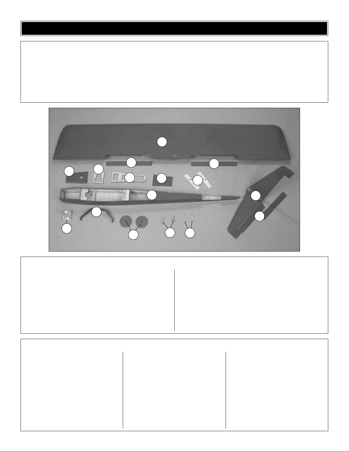
1 Wing and Ailerons
2 Tank Hatch
3 Throttle Ser vo Tray
4 V-tail Servo Tray
5 Ser vo Hatch
6 Hook and Loop Material
7 Fuselage
8 Engine Mount
9 Landing Gear
10 Wheels
11 Aileron Servo Rails
12 V-tail Servo Supports
13 V-tail with Ruddervators
(2) Aileron Torque Rod Horns
(5) Nylon Clevises
(2) 6" [150mm] Pushrods
(1) 11-3/4" Outer Pushrod Tube
(3) 17-1/2" [445mm] Pushrods
(5) Clevis Retainers
(4) Nylon Faslinks (GPMQ3820)
(1) Screw-Lock Connector (for throttle,
GPMQ3870)
(2) Control Horns w/Backplates
(4) 2-56 x 3/8" Control Horn Screws
(GPMQ3900)
(4) 6-32 x 1/2" [13mm] Socket Head Cap
Screws (to mount engine,
GPMQ3028)
(4) 8-32 x 1-1/2" [38mm] Flat-Head Screws
(to mount tail, wing,
GPMQ3052)
(2) 8-32 x 3/4" [38mm] Flat-Head Screws
(to mount wing, GPMQ3046)
(4) 6-32 x 1/4" Bolts (for main landing
gear, GPMQ3024)
(5) #2 x 3/8" Screws (to mount servo tray
and hatch, GPMQ3820)
(1) #2 Washers (to mount servo tray and
hatch, GPMR3400)
(1) 2" x 9" CA Hinge Strip (GPMQ3960)
(1) Tail Skid (GPMQ4445)
(2) Axles
Kit Contents (Photographed)
Kit Contents (Not Photographed)
Before starting to build, use the Kit Contents list to take an inventory of this kit to make sure it is complete, and inspect the
parts to make sure they are of acceptable quality. If any parts are missing or are not of acceptable quality, or if you need
assistance with assembly, contact Great Planes Product Support. When reporting defective or missing parts, use the par t
names exactly as they are written in the Kit Contents list on this page.
Great Planes Product Support:
Telephone: (217) 398-8970
Fax: (217) 398-7721
E-mail: airsupport@greatplanes.com
KIT CONTENTS
3
1
1
1
2
4
6
5
7
9
8
12
11
10
13
13
Page 7
❏ 1. If you have not yet done so already, remove the parts
of the kit from the box and inspect them for damage. If any
parts are damaged or missing, contact product suppor t at
the address or telephone number on page 6. Note: With
minor disassembly, the plane will fit back into the box. This
makes a great way to transport your plane to races.
❏ 2. Remove the masking tape and separate the ailerons
from the wing and the ruddervators from the V-tail. Where
necessary, use a covering iron with a covering sock to
tighten the covering that may have loosened during storage
or from removing the masking tape. Apply pressure over
sheeted areas and the servo openings to thoroughly bond
the covering to the wood.
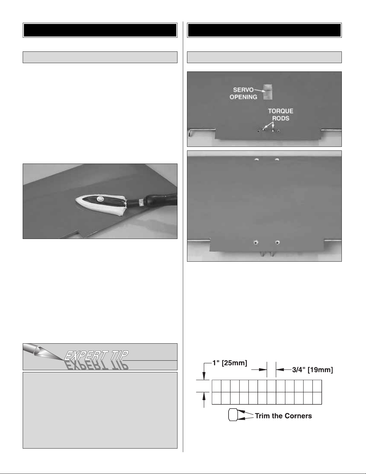
❏ 1. Looking at the bottom of the wing as shown in the top
photo (the aileron torque rods protrude from the bottom of
the wing), cut the covering from the servo opening and the
bottom of the four wing bolt holes. Tur n the wing over and
cut the covering from the top of the 4 bolt holes.
❏ 2. Cut six 3/4" x 1" [19 x 25mm] hinges from the 2" x 9"
[50 x 230mm] CA hinge strip.Snip the corners off so they go
in the hinge slots more easily.
Mount the Ailerons
BUILD THE WING & TAIL
All iron-on coverings sag due to extreme temperature and
humidity changes, often encountered during shipment
and warehouse storage. In nearly every case of an ARF
having sagged covering, this is the cause, and a quick
touch-up will solve the problem.To be sure, simply touch
up your model’s covering, then let it sit overnight. The
covering should remain taut and will be fine from here on.
If the covering has re-sagged significantly on any portion
of the model, please contact Product Support regarding
replacement.
Preparations
BUILDING INSTRUCTIONS
7
Page 8
❏ 3.Test fit, but do not glue the aileron to the wing with the
hinges. If you have difficulty inserting the hinges, insert a
#11 blade into the slot and carefully move it back and forth
to slightly widen the slot.
❏ 4. Separate the ailerons from the wing and take out all
the hinges.
❏ 5. Cut a small strip of covering from both sides of each
hinge slot. If not done the covering may interfere with the
penetration of the CA into the slot and the free movement of
the aileron.
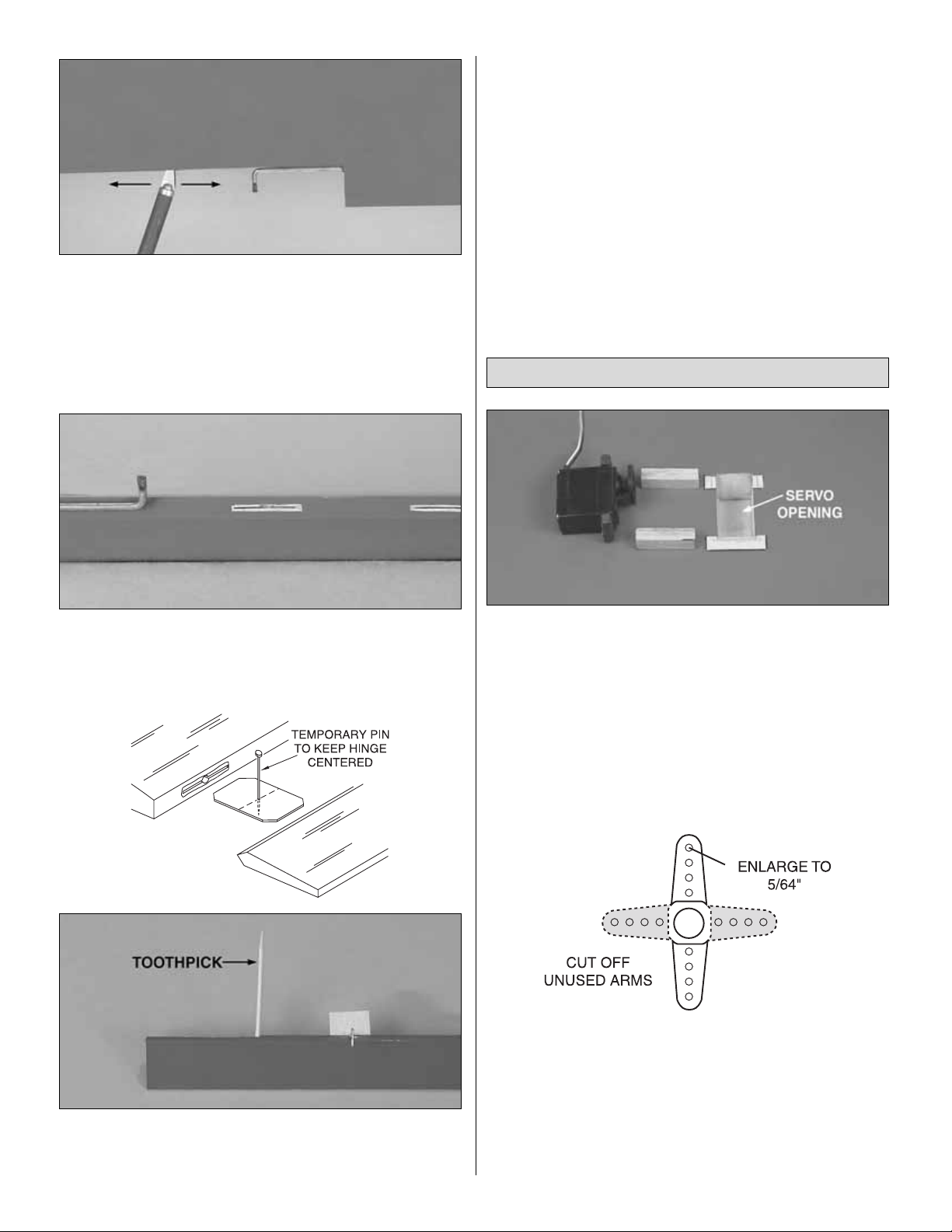
❏ 6. Stick a pin through the center of each hinge. Fit the
hinges into the ailerons. Use a toothpick to push epoxy into
the torque rod hole in the aileron.Fit the ailerons to the wing
with the hinges. The pin will keep the hinge centered.
Remove the pins from the hinges. Adjust the ailerons so
there is a small gap–just enough to see light through or to
slip a piece of paper through.
❏ 7. Apply six drops of thin CA to the top and bottom of
each hinge. Do not use CA accelerator. Gently work the
aileron up and down while the glue hardens. After the CA
has fully hardened, test the hinges by pulling on the
ailerons.
❏ 1. Test fit the aileron servo and the 3/8" x 3/8" x 1-1/4"
[9.5 x 9.5 x 32mm] basswood aileron servo rails in the wing.
Mark the covering around the rails. Remove the covering
from the contact area between the rails and the wing.Epoxy
the rails to the wing.
❏ 2. Mar k and drill 1/16" [1.6mm] holes through the servo
rails for the servo screws. Add a few drops of thin CA to the
holes and allow to fully harden. Mount the aileron servo
using the hardware that came with the servo.
❏ 3. Make a two-sided servo arm. Enlarge the holes in the
arm with a Hobbico Servo Horn Drill (or a #48 or 5/64"
[2mm]
drill bit) so the aileron pushrods will fit.
❏ 4. Thread both nylon torque rod horns onto the aileron
torque rods until the edge of the horn aligns with the edge
of the rods. Note: Tur ning a 6-32 tap through the hor ns will
make them turn onto the torque rods easier.
Install the Aileron Servo & Pushrods
8
Page 9

❏ 5. Thread a clevis 20 full turns onto each of the 6"
[150mm] pushrods.
❏ 6. Attach the clevises to the torque rod horns. With the
servo centered, the servo arm parallel to the LE of the wings
and the ailerons centered, use a fine-point felt-tip pen to
mark the spot that the pushrods cross the outermost holes
in the servo arm.
❏ 7.Slide the silicone retainers over the pushrods and onto
the clevises. Bend the pushrod upward 90 degrees on the
mark you made. Attach the pushrods to the ser vo arm with
two Faslinks .Cut off the excess pushrod. Be certain to leave
1/16" [2mm] of wire protruding from the Faslink as shown.
❏ 1. Cut the covering from the top and bottom of the V-tail
that covers both bolt holes. Cut the covering around the
hinge slots on the V-tail and the rudder vators the same as
you did with the wing. Permanently attach the ruddervators
to the V-tail the using the same hinging technique used with
the ailerons.
❏ 2.Bolt the V -tail to the fuse with two 8-32 x 1-1/2" [38mm]
flat-head screws.
❏ 3.Bolt the wing to the fuse with two 8-32 x 1-1/2" [38mm]
flat-head screws for the LE and two 8-32 x 3/4" [19mm] flathead screws for the TE.
❏ 4. Stand two to three yards or meters behind the plane
and sight straight down the center of the fuse. Without
moving side to side, approach the plane until you can see if
the LE of the V-tail aligns with the TE of the wing. If they do
not align, sand the high side of the wing saddle a small
amount
at a time until the wing and V-tail align with each other.
❏ 5.Mark the top LE of both ruddervators 1/2" [13mm] from
the inboard edge.
❏ 6.P osition the control horn centered ov er the mark.Mark
the hole locations on the ruddervators. Drill 1/16" [1.6mm]
holes through the ruddervators for mounting the control
Assemble & Mount the V-tail
9
Page 10

horns. Mount the control horn using 2-56 x 3/8" [9.5mm]
machine screws and the nylon backing plate on the bottoms
of the ruddervators. Note: Tur ning a 2-56 tap through the
back plate holes makes it easier to get the screws to thread
into the back plate.
❏ 7. If you removed the V-tail from the fuse, reinstall it.
Thread a clevis 15 full turns onto two of the 17-1/2" [445mm]
pushrods.
❏ 8. Trim the covering from the pushrod tube exits that are
in front of the V-tail on top of the fuse.
❏ 9. Slide the 17-1/2" [445mm] pushrods into the guide
tubes in the fuse. Connect the clevises to the outer hole on
the control horns. With the elevators centered, mark the
pushrods where they cross the V-tail joint.
❏ 10. Remove the pushrods. Make another mark 1-1/2"
[38mm] in front of the first. At the forward mark make a slight
bend. Reinstall the pushrods and attach the clevises. Note:
This bend is to make the pushrod move as freely as
possible in the pushrod tube. It may take several small
adjustments to get friction-free movement. It is worth the
effort, so take your time until there is no friction.
The engine mounting holes in the firewall fit both the
included universal aluminum engine mount and the
engine mount that comes with the Nelson .40 Quickee
500 engine.
The included engine mount will fit most .25 – .46 size
engines.
The bolt pattern of the mount is that of the Nelson .40. This
is to make it easy to upgrade to the Nelson, or experiment
from engine to engine.
❏ 1. Remove the bolts from the engine backplate.Test fit
the mount to the engine. If necessary, file the mount to
accommodate the needle valve (required if using the O.S.
®
.46 FX), or relocate the remote needle to the engine
mounting lug (required for the O.S..40 LA), as shown in the
photographs.
Mount the Engine
FINAL ASSEMBLY
10
Page 11

❏ 2.Temporarily mount the engine to the backplate engine
mount. Use a pushrod aligned with the carburetor arm to
determine the location for drilling the hole through the
engine mount. Mark the mount where the pushrod enters.
❏ 3. Remove the engine, and then drill a 3/16" [4.8mm]
hole through the mount at the mark. Position the mount on
the firewall with the hole you drilled nearest the bottom of
the fuselage. Bolt the engine mount to the firewall with four
6-32 x 1/2" [13mm] SHCS.
❏ 4. Use the hole in the mount as a guide to drill a 3/16"
[4.8mm] hole through the firewall.Note: It is okay if you drill
through a portion of the factory-installed blind nut on the
back of the firewall.Remove the mount.
❏ 5. Cut a 6" [150mm] piece off the 11-3/4" [300mm] outer
pushrod tube.Roughen one end of the 6" [152mm] pushrod
tube with coarse grit sandpaper.Glue the roughened end of
the pushrod tube to the firewall with 1/8" [3mm] protruding
from the front of the firewall.
❏ 6. Glue a 1" [25mm] square piece of light glass cloth to
the tube and the firewall.
❏ 7. Remove the engine mount from the firewall and the
engine from the engine mount.
❏ 8. Bend the tubes as shown, taking special care not to
kink them.
11
Page 12

❏ 9. Arrange the stopper and tubes as shown and insert
them into the tank.Tighten the screw to expand the stopper,
thus sealing the tank. Be cer tain the fuel line weight (clunk)
at the end of the fuel line inside the tank does not contact
the rear of the tank. Otherwise, the line may become stuck
above the fuel level and discontinue fuel flow.
❏ 10. Place a piece of 1/2" [13mm] foam in the bottom of
the tank compartment, but not over the outer throttle
pushrod.
❏ 11. Fit the tank into the fuselage. Mark the outside of the
fuselage in the approximate location of the fuel lines from
the tank.Remove the tank.Drill 1/4" [6mm] holes for the fuel
lines.Harden the wood around the holes you just drilled with
thin CA.
❏ 12. Guide a 12" [300mm] piece of fuel line through the
holes from the outside.Attach the lines to the tank and fit the
tank in place.
❏ 13. Mount your engine to the firewall with the 6-32 x 1/2"
[13mm] SHCS.
Note: The tank hatch will be glued in place later ; wait to do
this until after you balance the model, just in case any
weight is needed.
❏ 1. Mount the wheels to the landing gear with the 6-32 x
1/4" [6mm] bolts and axle as shown in the sketch.
❏ 2.Mount the landing gear to the fuse with two 6-32 x 1/4"
[6mm] bolts.
Mount the Landing Gear
12
Page 13

❏ 3. Remove the covering from the two tail-skid mounting
holes on the bottom of the fuse. Enlarge the tail-skid
mounting holes with a 1/8" [3mm] drill. Glue the nylon tailskid in place with medium CA.
Note: An alternate servo setup can be used if your radio
does not offer V-tail mixing and you want to have an active
rudder.See
“Optional Rudder Modifications,”
on page 16.
❏ 1. Trim the servo tray to fit your servos.
❏ 2. Glue the V-tail ser vo supports to the servo tray. The
side you glued the supports onto is now the bottom. Note: If
you used servos smaller than standard, fill the cut lines with
medium CA.
❏
3
.Fit the tail servos into the servo tray. Drill 1/16"
[1.6mm]
holes for the servo screws and apply thin CA to the holes.
Mount the servos to the tray with the screws provided with
the radio gear.
❏ 4. Glue the hook and loop material to the bottom of the
servo tray.
Install the Radio
13
Page 14

❏ 5. Attach your receiver and receiver battery to the top of
the servo tray. Use 1/4" [6mm] foam to isolate vibration, and
the included hook-and-loop material to hold them in place.
Remove the receiver and receiver batter y.
❏ 6.T aking y our time , slide the servo tr ay into the fuse.The
back of the servo tray fits into a notch in the f ormer .Because
of this, the back of the servo tray needs to be lifted as much
as possible while sliding the tray in place to get it positioned
properly.
❏ 7. Glue the servo tray to the fuse with thin CA, then with
thick CA.
❏ 8. Lift the plastic antenna tube up through the servo tray.
Reinstall the receiver and receiver battery.
❏ 9.Remov e the covering from the antenna tube exit at the
rear of the fuse.
❏ 10. Using an ar m cut off the aileron servo, put a strain
relief on the antenna and feed the antenna through the
antenna
tube. The excess antenna hangs out of the bottom
of the
airplane. DO NOT CUT THE ANTENNA.
❏ 11.Attach your receiv er and battery to the servo tray.Use
1/4" foam to isolate the receiver and battery from vibration.
❏ 12.Make three single-sided servo arms from three of the
six-sided arms provided with the servos. Enlarge the outer
two holes with a 1/16" [1.6mm] drill bit. Note: Even though
some of the photos show servo wheels, servo arms are
recommended.
14
Page 15

❏ 13.Slide the ruddervator pushrods into the pushrod
tubes
and connect the clevises to the control horns. Keeping the
ruddervator centered, mark the pushrod where it crosses
the center of the servo arm.
❏
14. Detach the clevises from the ruddervators and slide
the pushrods forward, lifting the front of the pushrods out of
the servo opening.
❏ 15. Bend the pushrods 90 degrees at the marks.
❏ 16. Using two Faslinks, connect the pushrods to the
outer hole of the servo arms we made in step 12.
❏ 17. Tur n on the radio and center the trims. Attach the
servo arms to the servos. Check that the ruddervators are
centered with the V-tail. Adjust the pushrods as required.
❏ 18. Mount the switch to the hatch in a location so it does
not interfere with anything when the hatch is in place or
place the switch in your preferred position.
❏ 19. Drill a 1/16" [1.6mm] hole through the front of the
hatch centered on the basswood rail at the front of the servo
opening. Use thin CA to harden the hole.
❏ 20.Secure the front of the hatch with a #2 x 3/8" [9.5mm]
screw and #2 washer.
❏ 21.Determine the size of the throttle servo you are going
to use. Using the photos as a reference, mount the throttle
servo in the tray so that it aligns with the throttle pushrod.Fit
the tray in the airplane, being sure to leave at least a 1/16"
[1.6mm] gap between the servo and the landing gear rail.
Glue the servo tray securely to the fuse sides.
❏ 22. Thread a clevis 15 full turns onto the last 17-1/2"
[445mm] pushrod. Note: The Nelson .40 requires a ball link
hookup.(The ball link is not included with this model.)
❏ 23. Slide the pushrod into the tube and attach the clevis
to the throttle arm.
❏ 24. Bend the pushrod straight up 1-1/2" [38mm] behind
the throttle arm. Do another 90° bend so that the pushrod
comes forward over the servo arm.
❏ 25 Connect the brass screw-lock connector to the servo
arm with the nylon retainer. Thread the 4-40 set screw a
couple of turns into the connector. Slide the connector onto
the throttle pushrod.
❏ 26.T urn on the radio and receiv er. Plug the throttle servo
into the throttle servo extension.Center the throttle stick and
install the servo arm 90 degrees to the servo.
15
Page 16

❏ 27. Center the carburetor barrel by moving the pushrod.
With the throttle servo and barrel centered, tighten the 4-40
set screw .Adjust the servo throw so at high throttle the
carburetor
barrel is completely open. Adjust the transmitter so at low
throttle the carburetor barrel is closed or slightly open.
Materials used for the following modifications are not
included
with this ARF. These modifications are
recommended
only if your radio does not have V-tail mixing.
❏ 1.Cut the tail of the fuse off 1/4" [6mm] behind the tail
skid.
❏ 2. Remove covering from the rudder.
❏ 3. Glue 1/4" x 1/2" x 1-1/2" [6 x 13 x 38mm] balsa to the
TE of the fuse and LE of the rudder
❏ 4. Shape the balsa on the fuse to match the shape of
the fuse.
❏ 5. Shape the balsa on the front of the rudder to match
the shape of the rudder.
❏ 6. Cover the rudder and the rear of the fuse.
❏ 7. Cut the hinge slots and mount the rudder with one
long hinge.
❏ 8. Sharpen the end of a 3/16" [5mm] brass tube.
Optional Rudder Modifications
16
Page 17

❏ 9. Use the brass tube to drill a hole through the fuse in
the approximate location and angles shown in the photo.
❏ 10. Slide a 3/16" [5mm] plastic pushrod outer tube (not
included) into the fuse from the rear, going through the large
opening in the former and aligning the front of it with the rear
of the servo mounts.Note:The servo tray is remo v ed f or
clarity.
❏ 11. Mark the pushrod tube where is exits the fuse. Use
course sandpaper to roughen the pushrod tube from the
mark to 1-1/2" [38mm] forward of the mark.
❏ 12. Glue the tube to the fuse with thin CA. Allow the CA
to cure and then cut off the excess tube.
❏ 13.Attach a small control horn (not included) to the
rudder
the same as was done with the ruddervators.Align the holes
in the horn with the hinge line.
❏ 14. Attach the pushrods to the rudder vators. Bend the
right ruddervator pushrod as shown. Connect the two
ruddervator pushrods together with two 5/32" [4mm] wheel
collars.
❏ 15. Attach the r udder pushrod to the right hand servo
with the Faslink as done with the other servo.
1.Use scissors or a sharp hobby knife to cut the decals from
the sheet.
2. Be certain the model is clean and free from oily
fingerprints and dust. Prepare a dishpan or small bucket
with a mixture of liquid dish soap and warm water–about
one teaspoon of soap per gallon of water. Submerse the
decal in the soap and water and peel off the paper backing.
Note: Even though the decals have a “sticky-back” and are
not the water transfer type, submersing them in soap &
water allows accurate positioning and reduces air bubbles
underneath.
3. Position the decal on the model where desired. Holding
the decal down, use a paper towel to wipe most of the
water away.
4. Use a piece of soft balsa or something similar to
squeegee remaining water from under the decal. Apply the
rest of the decals the same way.
Apply the Decals
17
Page 18

❏ 1. Turn on the transmitter and receiver and center the
trims. If necessar y, remove the ser vo arms from the ser vos
and reposition them so they are centered. Reinstall the
screws that hold on the servo arms.
❏ 2. With the transmitter and receiver still on, check all the
control surfaces to see if they are centered. If necessary,
adjust the clevises on the pushrods to center the control
surfaces.
❏ 3. Make certain that the control surfaces and the
carburetor respond in the correct direction as shown in the
diagram. If any of the controls respond in the wrong
direction, use the servo reversing in the transmitter to
reverse the servos connected to those controls. Be cer tain
the control surfaces have remained centered. Adjust if
necessary.
Use a Great Planes AccuThrow (or a ruler) to accurately
measure and set the control throw of each control surface
as indicated in the chart that follows. If your radio does not
have dual rates, we recommend setting the throws at the
low rate setting.
Note: The throws are measured at the widest part of the
elevators, rudder and ailerons.
At this stage the model should be in ready-to-fly condition
with all of the systems in place including the engine, landing
gear, cover ing and paint, and the radio system.
More than any other factor, the C.G. (balance point) can
have the greatest effect on how a model flies, and may
determine whether or not your first flight will be
successful. If you value this model and wish to enjoy it for
many flights, DO NOT OVERLOOK THIS IMPORTANT
PROCEDURE. A model that is not properly balanced will
be unstable and possibly unflyable.
Balance the Model (C.G.)
IMPORTANT: The Viper 500 ARF has been extensively
flown and tested to arrive at the throws at which it flies
best. Flying your model at these throws will provide you
with the greatest chance for successful first flights.If, after
you have become accustomed to the way the Viper 500
ARF flies, you would like to change the thro ws to suit y our
taste, that is fine. However, too much control throw could
make the model difficult to control, so remember , “more is
not always better.”
These are the recommended control surface throws:
High Rate Low Rate
ELEVATOR: 1/4" [6mm] up 1/8" [3mm] up
1/4" [6mm] down 1/8" [3mm] down
RUDDER: 1/4" [6mm] right
1/4" [6mm] left
AILERONS: 3/8" [9.5mm] up 1/8" [3mm] up
3/8" [9.5mm] down 1/8" [3mm] down
Set the Control Throws
Check the Control Directions
GET THE MODEL READY TO FLY
18
4-CHANNEL
TRANSMITTER
4-CHANNEL
TRANSMITTER
4-CHANNEL
TRANSMITTER
4-CHANNEL
TRANSMITTER
Page 19

❏ 1.Use a felt-tip pen or 1/8" [2mm] wide tape to accurately
mark the C.G.on the bottom of the wing on both sides of the
fuselage. The C.G. is located 3" [75mm] back from the
leading edge of the wing.
❏ 2.With the wing attached to the fuselage, all parts of the
model installed including the fuel tank hatch (ready-to-fly)
and an empty fuel tank, place the model as shown above on
a Great Planes CG Machine, or lift it at the balance point
you marked.
❏ 3. If the tail drops, the model is “tail heavy” and the
battery pack and/or receiver must be shifted forward or
weight must be added to the nose to balance. If the nose
drops, the model is “nose heavy” and the battery pack
and/or receiver must be shifted aft or weight must be added
to the tail to balance. If possible, relocate the battery pack
and receiver to minimize or eliminate any additional ballast
required. If additional weight is required, nose weight may
be easily added by using a “spinner weight”(GPMQ4645 for
the 1 oz.weight, or GPMQ4646 for the 2 oz.weight).If
spinner
weight is not practical or is not enough, use Great Planes
(GPMQ4485) “stick-on” lead. A good place to add stick-on
nose weight is in the fuel tank compartment. If there is not
sufficient space, then the firewall is an excellent mounting
location.Begin by placing incrementally increasing amounts
of weight on the firewall until the model balances.Once you
have determined the amount of weight required, it can be
permanently attached. If required, tail weight may be added
by cutting open the bottom of the fuse and gluing it
permanently inside. Glue the fuel tank hatch in place if nose
weight is needed.
Note: Do not rely upon the adhesive on the back of the lead
weight to permanently hold it in place. Over time, fuel and
exhaust residue may soften the adhesive and cause the
weight to fall off. Use #2 sheet metal screws, RTV silicone
or epoxy to permanently hold the weight in place.
❏ 4. IMPORTANT: If you found it necessary to add any
weight, recheck the C.G.after the weight has been installed.
❏ 5. REMEMBER: Now that the model is balanced, glue
the tank hatch in place.
❏ 1. With the wing level, have an assistant help you lift the
model by the engine propeller shaft and the bottom of the
fuse under the TE of the fin.Do this several times.
❏ 2. If one wing always drops when you lift the model, it
means that side is heavy. Balance the airplane by adding
weight to the other wing tip. An airplane that has been
laterally
balanced will track better in loops and other
maneuvers.
No matter if you fly at an AMA sanctioned R/C club site or if
you fly somewhere on your own, you should always have
your name, address, telephone number and AMA number
on or inside your model. It is required at all AMA R/C club
flying sites and AMA sanctioned flying events. Fill out the
identification tag on page 23 and place it on or inside
your model.
Follow the battery charging instructions that came with your
radio control system to charge the batteries. You should
always charge your transmitter and receiver batteries the
night before you go flying, and at other times as
recommended by the radio manufacturer.
Charge the Batteries
Identify Y our Model
PREFLIGHT
Balance the Model Laterally
This is where your model should balance for the first
flights. Later, you may wish to experiment by shifting the
C.G. up to 2-5/8" [67mm] forward or 3-3/8" [86mm] back
to change the flying characteristics. Moving the C.G.
forward may improve the smoothness and stability, but
the model may then require more speed for takeoff and
make it more difficult to slow for landing.Moving the C.G.
aft makes the model more maneuverable, but could also
cause it to become too difficult to control. In any case,
start at the recommended balance point and do not at
any time balance the model outside the specified range.
19
Page 20

Note: Checking the condition of your receiver battery pack
is highly recommended. All battery packs, whether it’s a
trusty pack you’ve just taken out of another model, or a new
battery pack you just purchased, should be cycled, noting
the discharge capacity. Oftentimes, a weak battery pack can
be identified (and a valuable model sav ed!) b y comparing its
actual capacity to its rated capacity. Refer to the instructions
and recommendations that come with your cycler. If you
don’t own a battery cycler, perhaps you can have a friend
cycle your pack and note the capacity for you.
Carefully balance your propeller and spare propellers before
you fly. An unbalanced prop can be the single most
significant cause of vibration that can damage your model.
Not only will engine mounting screws and bolts loosen,
possibly with disastrous effect, but vibration may also
damage your radio receiver and battery. Vibration can also
cause your fuel to foam, which will, in turn, cause your
engine to run hot or quit.
We use a Top Flite Precision Magnetic Prop Balancer
™
(TOPQ5700) in the workshop and keep a Great Planes
Fingertip Prop Balancer (GPMQ5000) in our flight box.
If the engine is new, follow the engine manufacturer’s
instructions to break-in the engine. After break-in,
confirm that the engine idles reliably, transitions smoothly
and rapidly to full power and maintains full
power–indefinitely.
After you run the engine on the model, inspect the model
closely to make sure all screws remained tight, the hinges
are secure, the prop is secure and all pushrods and
connectors are secure.
Ground check the operational range of your r adio bef ore the
first flight of the day. With the transmitter antenna collapsed
and the receiver and transmitter on, most radio systems
indicate you should be able to walk at least 100 feet away
from the model and still have control. Have an assistant
stand by your model and, while you work the controls, tell
you what the control surfaces are doing. Repeat this test
with the engine running at various speeds with an
assistant holding the model, using hand signals to show you
what is happening. If the control surfaces do not respond
correctly, do not fly! Find and correct the problem first. Look
for loose servo connections or broken wires, corroded wires
on old servo connectors, poor solder joints in your battery
pack or a defective cell, or a damaged receiver crystal from
a previous crash.
Keep all engine fuel in a safe place, away from high heat,
sparks or flames, as fuel is very flammable. Do not smoke
near the engine or fuel; and remember that engine exhaust
gives off a great deal of deadly carbon monoxide .Therefore,
do not run the engine in a closed room or garage.
Get help from an experienced pilot when learning to operate
engines.
Use safety glasses when starting or running engines.
Do not run the engine in an area of loose gravel or sand;the
propeller may throw such material in your face or eyes.
Keep your f ace and body as well as all spectators a wa y from
the plane of rotation of the propeller as you start and run
the engine.
Keep these items away from the prop: loose clothing, shirt
sleeves, ties, scarfs, long hair or loose objects such as
pencils or screwdrivers that may fall out of shir t or jacket
pockets into the prop.
Use a “chicken stick” or electric star ter to start the engine.
Do not use your fingers to flip the propeller .Make certain the
glow plug clip or connector is secure so that it will not pop
off or otherwise get into the running propeller.
Make all engine adjustments from behind the rotating
propeller.
The engine gets hot! Do not touch it during or right after
operation.Make sure fuel lines are in good condition so fuel
will not leak onto a hot engine, causing a fire.
To stop a glow engine, cut off the fuel supply by closing off
the fuel line or following the engine manufacturer’s
recommendations. Do not use hands, fingers or any other
body part to try to stop the engine. To stop a gasoline
powered engine, an on/off switch should be connected to
the engine coil. Do not throw anything into the propeller of a
running engine.
Failure to follow these safety precautions may result
in severe injury to yourself and others.
ENGINE SAFETY PRECAUTIONS
Range Check
Ground Check
Balance the Propellers
20
Page 21

Read and abide by the following Academy of Model
Aeronautics Official Safety Code:
GENERAL
1. I will not fly my model aircraft in sanctioned events, air
shows, or model flying demonstrations until it has been
proven to be airworthy by having been previously
successfully flight tested.
2. I will not fly my model aircraft higher than approximately
400 feet within 3 miles of an airport without notifying the
airport operator.I will give right of way to, and avoid flying in
the proximity of full-scale aircraft. Where necessary an
observer shall be used to supervise flying to avoid having
models fly in the proximity of full-scale aircraft.
3.Where established, I will abide by the safety rules for the
flying site I use, and I will not willfully and deliberately fly my
models in a careless, reckless and/or dangerous manner.
7. I will not fly my model unless it is identified with my name
and address or AMA number, on or in the model.
9. I will not operate models with pyrotechnics (any device
that explodes, burns, or propels a projectile of any kind).
RADIO CONTROL
1.I will have completed a successful radio equipment
ground
check before the first flight of a new or repaired model.
2. I will not fly my model aircraft in the presence of
spectators until I become a qualified flier, unless assisted b y
an experienced helper.
3. I will perform my initial turn after takeoff away from the pit
or spectator areas, and I will not thereafter fly over pit or
spectator areas, unless beyond my control.
4. I will operate my model using only radio control
frequencies currently allowed by the F ederal
Communications
Commission.
❏ 1. Fuelproof all areas exposed to fuel or exhaust
residue such as the tank compartment and
underside of hatch, wing saddle area, etc.
❏ 2. Check the C.G. according to the measurements
provided in the manual.
❏ 3. Be certain the battery and receiver are securely
mounted in the fuse.Simply stuffing them into place
with foam rubber is not sufficient.
❏ 4. Extend your receiver antenna and make sure it has
a strain relief inside the fuselage to keep tension off
the solder joint inside the receiver and hasn’t been
cut, shortened or otherwise damaged.
❏ 5. Balance your model
laterally
as explained in the
instructions.
❏ 6. Use thread-locking compound to secure critical
fasteners such as the set screws that hold the
wheel axles, screws that hold the carburetor arm (if
applicable), screw-lock pushrod connectors, etc.
❏ 7. Add a drop of oil to the axles so the wheels will
turn freely.
❏ 8. Make sure all hinges are securely glued in place.
❏ 9. Reinforce holes for wood screws with thin CA where
appropriate (servo mounting screws, cowl mounting
screws, etc.).
❏ 10. Confirm that all controls operate in the correct
direction and the throws are set up according to
the manual.
❏ 11. Make sure there are silicone retainers on all the
clevises and that all servo arms are secured to the
servos with the screws included with your radio.
❏ 12. Secure connections between servo wires and
Y-connectors or servo extensions, and the
connection between your battery pack and the
on/off switch with vinyl tape, heat shrink tubing or
special clips suitable for that purpose.
❏ 13. Make sure any servo e xtension cords y ou ma y ha v e
used do not interfere with other systems (servo
arms, pushrods, etc.).
❏ 14. Secure the pressure tap (if used) to the muffler with
high temp RTV silicone, thread-locking compound
or J.B.Weld.
❏ 15. Make sure the fuel lines are connected and are
not kinked.
❏ 16. Balance your propeller (and spare propellers).
❏ 17. Tighten the propeller nut and spinner.
❏ 18. Place your name, address, AMA number and
telephone number on or inside your model.
❏ 19. Cycle your receiver battery pack (if necessary) and
make sure it is fully charged.
❏ 20. If you wish to photograph your model, do so before
your first flight.
❏ 21. Range check your radio when you get to the flying
field.
During the last few moments of preparation your mind
may be elsewhere anticipating the excitement of the first
flight. Because of this, you may be more lik ely to overlook
certain checks and procedures that should be performed
before the model is flown.To help avoid this, a check list
is provided to make sure these important areas are not
overlooked. Many are covered in the instruction manual,
so where appropriate, refer to the manual for complete
instructions. Be sure to check the items off as they are
completed (that’s why it’s called a
check list!
).
CHECK LIST
AMA SAFETY CODE (excerpt)
21
Page 22

The Viper 500 is a great-flying sport and racing model that
flies smoothly and predictably, but incredibly fast.The Viper
500 does not, however, possess any of the self-recovery
characteristics of a primary R/C trainer and should be flown
only by experienced R/C pilots.
For longevity of your engine, especially if it is new, the fuel
mixture should be richened so the engine runs at about 400
RPM below peak speed.By running the engine slightly rich,
you will help prevent dead-stick landings caused by
overheating.
Remember to takeoff into the wind.When you’re ready, point
the model straight down the runway,
GO
TO HIGH RATES
,
then gradually advance the throttle. One of the most
important things to remember with a tail dragger is to always
be ready to apply right rudder to counteract engine torque.
Gain as much speed as your runway and flying site will
practically allow before gently applying up elevator, lifting
the model into the air.At this moment it is likely that you will
need to apply more right rudder to counteract engine
torque. Be smooth on the elevator stick, allowing the model
to establish a gentle climb to a safe altitude before turning
into the traffic pattern. Go to low rates as soon as the model
has picked up speed.
For reassurance and to keep an eye on other traffic, it is a
good idea to have an assistant on the flight line with you.Tell
him to remind you to throttle back once the plane gets to a
comfortable altitude. While full throttle is usually desirable
for takeoff on sport models, it is NOT required for the Viper
500, and the model will fly far more smoothly and allow you
more time to react and learn the aircraft at reduced speeds.
Take it easy with the Viper 500 for the first few flights,
gradually getting acquainted with it as you gain confidence.
Adjust the trims to maintain straight and level flight. After
flying around for a while, and while still at a saf e altitude with
plenty of fuel, practice slow flight and execute practice
landing approaches by reducing the throttle to see how the
model handles at slower speeds.Add power to see how the
Viper 500 climbs as well. Continue to fly around, executing
various maneuvers and making mental notes (or having
your assistant write them down) of what trim or C.G.
changes may be required to fine tune the model so it flies
Flight
Takeoff
CAUTION (THIS APPLIES TO ALL
R/C AIRPLANES): If,
while flying, you notice any unusual sounds, such as a
low-pitched “buzz,” this may indicate control surface
flutter
. Because flutter can quickly destroy components of
your airplane, any time you detect flutter you must
immediately cut the throttle and land the airplane! Check
all servo grommets for deterioration (this may indicate
which surface fluttered), and make sure all pushrod
linkages are secure and free of play. If the control surface
fluttered once, it probably will flutter again under similar
circumstances unless you can eliminate the free-play or
flexing in the linkages. Here are some things which can
cause flutter: Excessive hinge gap; Not mounting control
horns solidly; Poor fit of clevis pin in horn; Side-play of
pushrod in guide tube caused by tight bends; Poor fit of
Z-bend in servo arm; Insufficient glue used when gluing in
the elevator joiner wire; Excessive
play
or
backlash
in
servo gears; and Insecure ser vo mounting.
Fuel Mixture Adjustments
CAUTION SPECIFICALLY FOR QUICKIE 500 AND
OTHER RACE-STYLE AIRCRAFT: These models are
designed to fly VERY quickly.Their top speed is twice that
of the typical sport model, or more. As such, there are
several rules which are CRITICAL to safely flying these
aircraft. Many of the rules for flying a model of this sort –
such as using high rates for take-off and not for nor mal
flying – are likely diff erent from most models y ou are used
to, so please take these cautions seriously.
1. Take-off is very short. Use HIGH RATES for takeoff
or you will not have sufficient elevator to properly
handle the aircraft.As soon as it starts to come up to
speed you MUST go to low rates.
2. For your first flights, be sure the engine is tuned
slightly rich and plan to fly around at half throttle or
less, getting used to the model’s feel, tr ims, etc.
3. Trim is absolutely critical. If the aircraft cannot cover
the length of your field hands off without banking,
climbing or diving, it is unlikely the model will
complete the flight safely.
4. These models are VERY, VERY aerodynamic. As
such, their glide paths are far longer than that of
similar sized sport models – typically 2 or even 3
times
the length, requiring HIGH RATE elevator to flair.
5. Because of the speed at which the Viper travels
when wide open, minimal control throws are needed
to effect change. As such, the model must be flown
on low rates for those conditions. However, any time
the model’s speed is decreased, high rates are
REQUIRED to provide enough control to fly safely.
6. Landings, and especially flaring, MUST be done on
high rates.The model will not flair on low rates, and
will not flair from a slow speed nose-down attitude
even on high rates. Be sure to practice low speed
flight several times at a good altitude until you are
used to the model’s handling.
FLYING
22
Page 23

the way you like. Mind your fuel level, but use this first flight
to become familiar with your model before landing.
REMEMBER to use high rates when practicing slow speed
flight for sufficient control.
To initiate a landing approach, lower or “cut” the throttle
while on the downwind leg. GO TO HIGH RATE
ELEVATOR. Allow the nose of the model to pitch only very
slightly downward to gradually b leed off altitude.Continue to
lose altitude, but maintain airspeed by keeping the nose
down only slightly as you turn onto the crosswind leg.Make
your final turn toward the runway (into the wind) k eeping the
nose
only slightly
down to maintain airspeed and control.
Level the attitude when the model reaches the runway
threshold, modulating the throttle as necessary to maintain
your glide path and airspeed. If you are going to overshoot,
smoothly advance the throttle (always ready on the right
rudder to counteract torque) and climb out to make another
attempt. When you’re ready to make your landing flare and
the model is inches off the deck, smoothly increase up
elevator until it gently touches down. Once the model is on
the runway and has lost flying speed, hold up elevator to
place the tail on the ground, regaining tail wheel control.
One final note about flying your model.Have a goal or flight
plan in mind for every flight. This can be flying the model
more quickly, working on tighter pylon turns, or practicing
mock landing approaches at altitude.
Always remember to
be aware of the relationship between a race model’s
airspeed and the responsiveness of its flight controls.
A
flight plan greatly reduces the chances of crashing your
model just because of poor planning and impulsive moves.
Remember to think.
Have a ball! But always stay in control and fly in a safe
manner.
GOOD LUCK AND GREAT FLYING!
O. S.®.46 FX Engine
Engineered for superior, long-lasting power in sport aircraft,
the .46 FX has dual ball bearings for durability and smooth
operation, plus a low crankcase design that allows for a
taller head to improve cooling.For added safety, the needle
valve is remotely mounted and the crankshaft has a longer
threaded portion to allow secure engagement of the prop,
nut and spinner.The engine also uses O. S. Engines’ ABN
construction – an aluminum piston with Advanced BiMetallic Liner of nickel and brass. ABN construction
increases durability and provides more consistent plating,
resulting in better compression due to the precise fit
between the piston
and sleeve. Includes muffler and 2-year
warranty.
OSMG0546
Futaba®9CAP 9-Channel Radio Systems
Want to experiment with
triple
rates? Find, open, set and
close functions with amazing ease? Be able to look at an
LCD and see how far each servo will travel in operation –
and reset the limits of any servo you choose? You can do it
all and more, with the 9CAP.Easy Dial N’Key programming,
eight-character naming, and a “full functionality” trainer
system are just a few of its extraordinary features. Learn
more on the Futaba website at
www.futaba-rc.com
.Includes
R149DP receiver, four S3001 servos, 600mAh Tx and Rx
NiCds. FUTJ87**
OTHER ITEMS AVAILABLE FROM
GREAT PLANES
Landing
23
Page 24

BUILDING NOTES
Kit Purchased Date: _______________________
Where Purchased: _________________________
Date Construction Started: __________________
Date Construction Finished: _________________
Finished Weight: __________________________
Date of First Flight: ________________________
FLIGHT LOG
 Loading...