

Page 1
™
INSTRUCTION MANUAL
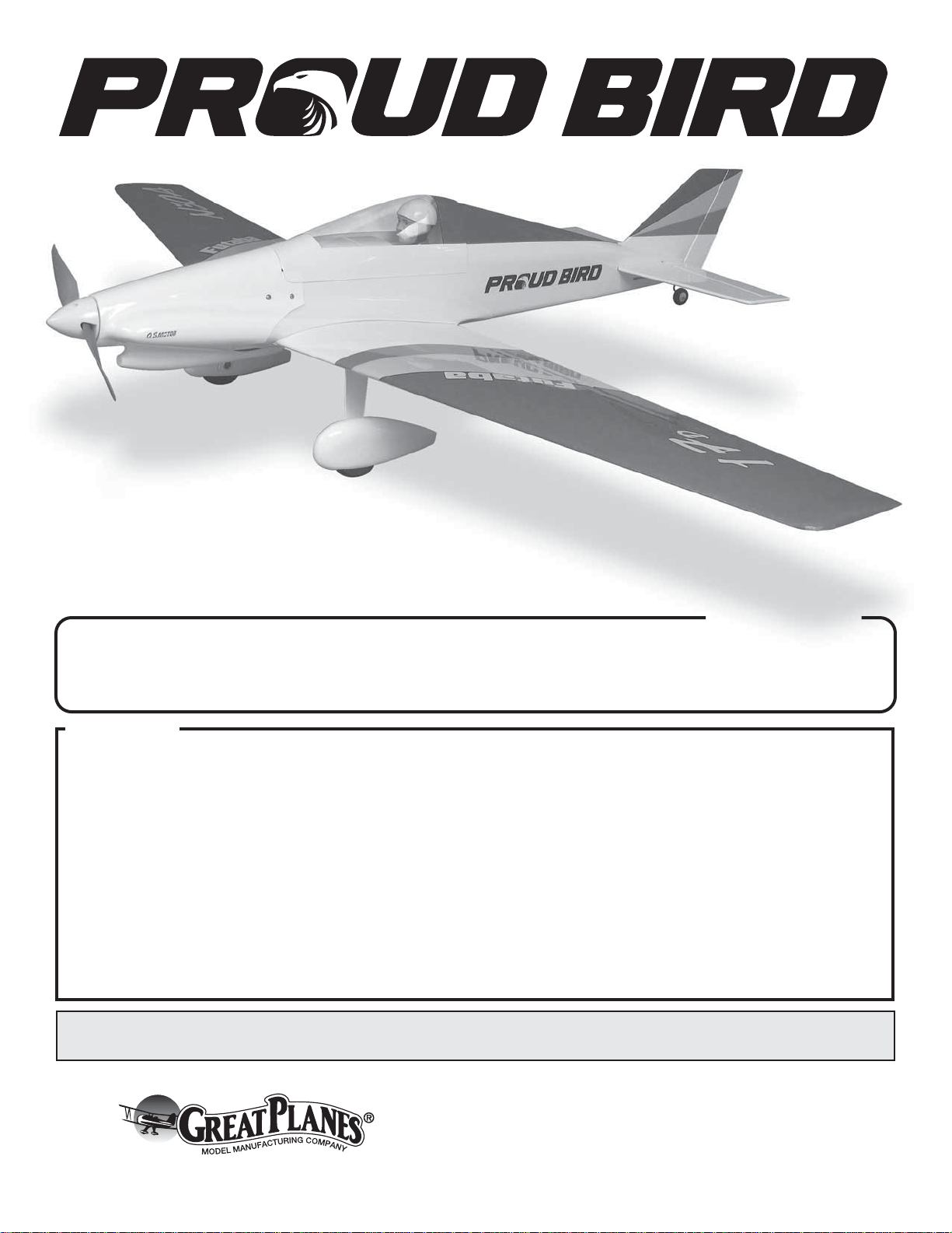
Wingspan: 51-15/16 in [1319 mm]
2
Wing Area: 388 in
Wing Loading: 18−21 oz/ ft
[25 dm2]
2
[55−64 g/dm2]
WARRANTY
Great Planes® Model Manufacturing Co. guarantees this kit to
be free from defects in both material and workmanship at the
date of purchase. This warranty does not cover any component
parts damaged by use or modification. In no case shall Great
Planes’ liability exceed the original cost of the purchased kit.
Further, Great Planes reserves the right to change or modify this
warranty without notice.
In that Great Planes has no control over the final assembly or
material used for final assembly, no liability shall be assumed nor
accepted for any damage resulting from the use by the user of
the final user-assembled product. By the act of using the
user-assembled product, the user accepts all resulting liability.
If the buyer is not prepared to accept the liability associated
with the use of this product, the buyer is advised to return
Weight: 3− 3.5 lb [1360 −1590 g]
Length: 40 in [1015 mm]
Radio: 4+ channels
this kit immediately in new and unused condition to the
place of purchase.
To make a warranty claim send the defective part or item to
Hobby Services at the address below:
Include a letter stating your name, return shipping address, as
much contact information as possible (daytime telephone
number, fax number, e-mail address), a detailed description of
the problem and a photocopy of the purchase receipt. Upon
receipt of the package the problem will be evaluated as quickly
as possible.
SPECIFICATIONS
Electric
Power:
Hobby Services
3002 N. Apollo Dr. Suite 1
Champaign IL 61822 USA
1200kV Outrunner
Brushless Motor
READ THROUGH THIS MANUAL BEFORE STARTING CONSTRUCTION. IT CONTAINS IMPORTANT
INSTRUCTIONS AND WARNINGS CONCERNING THE ASSEMBLY AND USE OF THIS MODEL.
Entire Contents © 2012 Hobbico,® Inc. All rights reserved.
Champaign, Illinois (217) 398-8970
E-mail: airsupport@greatplanes.com
GPMA1260 Mnl
Page 2
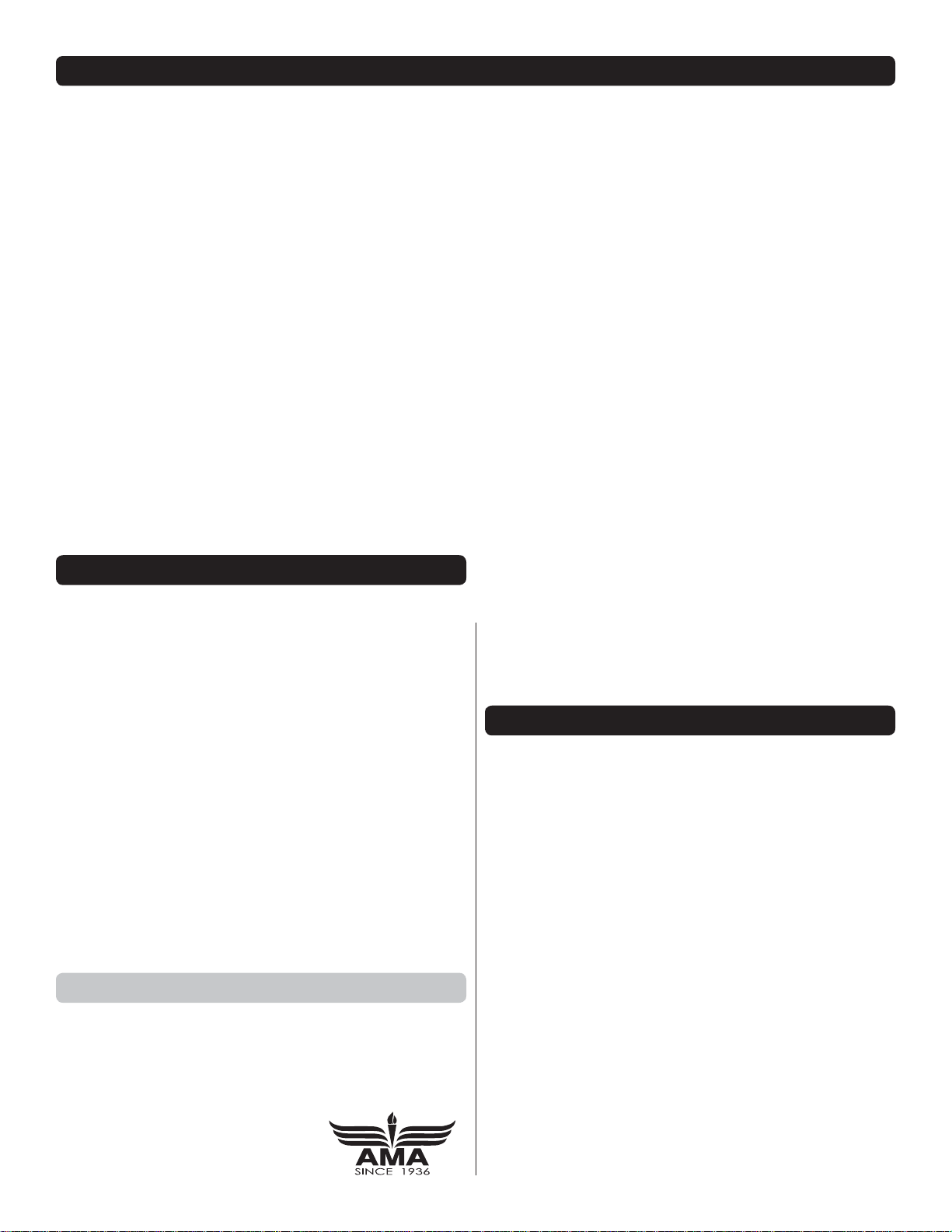
TABLE OF CONTENTS
INTRODUCTION . . . . . . . . . . . . . . . . . . . . . . . . . . . . . . . . 2
AMA . . . . . . . . . . . . . . . . . . . . . . . . . . . . . . . . . . . . . . . 2
SAFETY PRECAUTIONS . . . . . . . . . . . . . . . . . . . . . . . . . 2
DECISIONS YOU MUST MAKE. . . . . . . . . . . . . . . . . . . . . 3
Battery Recommendations. . . . . . . . . . . . . . . . . . . . . . 3
Radio Equipment . . . . . . . . . . . . . . . . . . . . . . . . . . . . . 3
Motor Recommendations. . . . . . . . . . . . . . . . . . . . . . . 3
ADDITIONAL ITEMS REQUIRED . . . . . . . . . . . . . . . . . . . 3
Propeller. . . . . . . . . . . . . . . . . . . . . . . . . . . . . . . . . . . . 3
Adhesives and Building Supplies. . . . . . . . . . . . . . . . . 4
Optional Supplies and Tools. . . . . . . . . . . . . . . . . . . . . 4
Building Stand . . . . . . . . . . . . . . . . . . . . . . . . . . . . . . . 4
IMPORTANT BUILDING NOTES. . . . . . . . . . . . . . . . . . . . 4
KIT INSPECTION. . . . . . . . . . . . . . . . . . . . . . . . . . . . . . . . 5
ORDERING REPLACEMENT PARTS . . . . . . . . . . . . . . . . 5
KIT CONTENTS. . . . . . . . . . . . . . . . . . . . . . . . . . . . . . . . . 5
PREPARATIONS . . . . . . . . . . . . . . . . . . . . . . . . . . . . . . . . 6
ASSEMBLE THE MODEL . . . . . . . . . . . . . . . . . . . . . . . . . 6
Build the Wing . . . . . . . . . . . . . . . . . . . . . . . . . . . . . . . 6
Assemble the Tail Section . . . . . . . . . . . . . . . . . . . . . 10
Install the Power System . . . . . . . . . . . . . . . . . . . . . . 15
Assemble & Install the Landing Gear. . . . . . . . . . . . . 17
Install the Wing Fairings, Belly Pan & Cockpit Floor . 17
Finish the Model. . . . . . . . . . . . . . . . . . . . . . . . . . . . . 19
Apply the Decals . . . . . . . . . . . . . . . . . . . . . . . . . . . . 21
GET THE MODEL READY TO FLY . . . . . . . . . . . . . . . . . 21
Check the Control Directions . . . . . . . . . . . . . . . . . . . 21
Set the Control Throws. . . . . . . . . . . . . . . . . . . . . . . . 21
ESC Setup . . . . . . . . . . . . . . . . . . . . . . . . . . . . . . . . . 22
Balance the Model (C.G.). . . . . . . . . . . . . . . . . . . . . . 22
Balance the Model Laterally. . . . . . . . . . . . . . . . . . . . 23
PREFLIGHT . . . . . . . . . . . . . . . . . . . . . . . . . . . . . . . . . . . 23
Identify Your Model. . . . . . . . . . . . . . . . . . . . . . . . . . . 23
Charge the Batteries . . . . . . . . . . . . . . . . . . . . . . . . . 23
Balance Propellers. . . . . . . . . . . . . . . . . . . . . . . . . . . 23
Ground Check & Range Check . . . . . . . . . . . . . . . . . 24
MOTOR SAFETY PRECAUTIONS . . . . . . . . . . . . . . . . . 24
AMA SAFETY CODE EXCERPTS . . . . . . . . . . . . . . . . . 24
General . . . . . . . . . . . . . . . . . . . . . . . . . . . . . . . . . . . 24
Radio Control . . . . . . . . . . . . . . . . . . . . . . . . . . . . . . . 24
CHECK LIST . . . . . . . . . . . . . . . . . . . . . . . . . . . . . . . . . . 24
FLYING. . . . . . . . . . . . . . . . . . . . . . . . . . . . . . . . . . . . . . . 25
Takeoff . . . . . . . . . . . . . . . . . . . . . . . . . . . . . . . . . . . . 25
Flight . . . . . . . . . . . . . . . . . . . . . . . . . . . . . . . . . . . . . 25
Landing . . . . . . . . . . . . . . . . . . . . . . . . . . . . . . . . . . . 26
TRIMMING THE PROUD BIRD FOR RACING. . . . . . . . 26
INTRODUCTION
Congratulations on your purchase of the Great Planes Proud
Bird ARF! The Proud Bird was specifi cally designed to be a
fast, precision airframe while maintaining the requirements of
the NMPRA Electric Formula One (EF1) racing rules (the rules
can be found at nmpra.org). Accommodations are provided
to install different brushless motors that are allowable per the
race rules. You will fi nd that the Proud Bird is a pleasure to
build as it assembles quickly.
Although the Proud Bird was made for racing, it makes a great
sport fl ier as well. The Proud Bird can be fl own with a .15 size
brushless motor and a 3S battery which will give you longer
fl ight times and a more casual fl ight envelope.
For the latest technical updates or manual corrections to the
Proud Bird visit the Great Planes web site at www.greatplanes.
com. Open the “Airplanes” link, then select the Proud Bird
ARF. If there is new technical information or changes to this
model a “tech notice” box will appear in the upper left corner
of the page.
AMA
If you are not already a member of the AMA (Academy of
Model Aeronautics), please join! The AMA is the governing
body of model aviation and membership provides liability
insurance coverage, protects modelers’ rights and interests
and is required to fl y at most R/C sites.
Academy of Model Aeronautics
5151 East Memorial Drive
Muncie, IN 47302-9252
Tele. (800) 435-9262 Fax (765) 741-0057
Or via the Internet at: http://www.modelaircraft.org
IMPORTANT!!! Two of the most important things you can
do to preserve the radio controlled aircraft hobby are to avoid
fl ying near full-scale aircraft and avoid fl ying near or over
groups of people.
SAFETY PRECAUTIONS
PROTECT YOUR MODEL, YOURSELF & OTHERS…
FOLLOW THESE IMPORTANT SAFETY PRECAUTIONS
1. Your Proud Bird ARF should not be considered a toy, but
rather a sophisticated, working model that functions very
much like a full-size airplane. Because of its performance
capabilities, the Proud Bird, if not assembled and operated
correctly, could possibly cause injury to yourself or spectators
and damage to property.
2. You must assemble the model according to the instructions.
Do not alter or modify the model, as doing so may result in an
unsafe or unfl yable model. In a few cases the instructions may
differ slightly from the photos. In those instances the written
instructions should be considered as correct.
3. You must take time to build straight, true and strong.
4. You must use an R/C radio system that is in good condition,
a correctly sized motor, and other components as specifi ed
in this instruction manual. All components must be correctly
installed so that the model operates correctly on the ground
and in the air. You must check the operation of the model and
all components before every fl ight.
2
Page 3

5. If you are not an experienced pilot or have not fl own this type
of model before, we recommend that you get the assistance
of an experienced pilot in your R/C club for your fi rst fl ights.
If you’re not a member of a club, your local hobby shop has
information about clubs in your area whose membership
includes experienced pilots.
6. WARNING: The cowl and wheel pants included in this kit
are made of fi berglass, the fi bers of which may cause eye,
skin and respiratory tract irritation. Never blow into a part
(wheel pant, cowl) to remove fi berglass dust, as the dust
will blow back into your eyes. Always wear safety goggles, a
particle mask and rubber gloves when grinding, drilling and
sanding fi berglass parts. Vacuum the parts and the work area
thoroughly after working with fi berglass parts.
must also be purchased separately. A suitable power supply
for the PolyCharge4 is the Great Planes 12V 12A DC power
supply. Part numbers for the products mentioned here are:
❍ Great Planes ElectriFly Triton Jr DC Computer
Charger (GPMM3152)
❍ Great Planes PolyCharge4 DC 4 Output LiPo Charger
(GPMM3015)
❍ Great Planes ElectriFly Equinox LiPo Cell Balancer
(GPMM3160)
❍ Great Planes 12V 12A Switching DC Power Supply
(GPMP0901)
Radio Equipment
We, as the kit manufacturer, provide you with a top quality,
thoroughly tested kit and instructions, but ultimately the
quality and fl yability of your fi nished model depends on how
you build it; therefore, we cannot in any way guarantee the
performance of your completed model, and no representations
are expressed or implied as to the performance or safety of
your completed model.
Remember: Take your time and follow the instructions to
end up with a well-built model that is straight and true.
DECISIONS YOU MUST MAKE
This is a partial list of items required to fi nish the Proud Bird
that may require planning or decision making before starting
to build. Order numbers are provided in parentheses.
Battery Recommendations
The recommended battery for the Proud Bird that meets EF1
rules for maximum voltage and weight is:
❍ FlightPower LiPo Pro50 4S 14.8V 2550mAh 50C
(FPWP5041)
In addition to a battery, a LiPo battery charger is also required
and there are several that will work (depending on your budget
and requirements). A safe, economical charger is the Great
Planes ElectriFly Triton Jr DC Computer Charger. TheTriton
Jr will require a DC power source as well as a Great Planes
Equinox™ LiPo Cell Balancer in order to safely charge LiPo
batteries. If wall charging is a priority, an AC 12-Volt power
source must also be purchased separately. A suitable power
supply for the PolyCharge4 is the Great Planes 12V 12A DC
power supply. Some pilots prefer to have several batteries
and charge them faster so they can fl y more. For charging
up to four batteries faster at the same time, the Great Planes
PolyCharge4™ DC-powered LiPo charger is recommended.
Like the Triton Jr, the PolyCharge4 does not have an internal
LiPo cell balancer which is a critical component in making sure
your LiPo batteries charge effi ciently and evenly. So, for each
LiPo battery you wish to charge simultaneously, one Great
Planes Equinox™ LiPo Cell Balancer will also be required.
Finally, the PolyCharge4 does not have AC capability, so if
wall charging is a priority, a separate AC 12-Volt power source
Three micro servos are required for the Proud Bird. Futaba
S3115 micro servos are shown in the manual. S3102 micro
servos can also be used.
❍ Futaba S3115 Micro Precision Servo (FUTM0415)
❍ Futaba S3102 Aircraft Micro Metal Gears Servo
(FUTM0034)
Motor Recommendations
The O.S. .25 brushless motor is shown in the assembly
instructions of this manual. Also recommended is the RimFire
35-45-1200 motor. A 60A minimum ESC is also required. We
recommend the Castle Creations Ice Lite 75A ESC. If using
the recommended ESC, you will also need to purchase a male
Deans Ultra connector. Part numbers for these recommended
components are provided below.
❍ O.S. .25 Brushless Motor (OSMG9525)
❍ RimFire EF 1 35-45-1200 Motor (GPMG4630)
❍ Castle Creations Phoenix Ice Lite 75 25V ESC
(CSEM7000)
❍ W.S. Deans® Male Ultra Plug® (2) (WSDM1302)
The Proud Bird is not just for racing. It is a very capable
sport plane and fl ies well using a more conservative power
system. Part numbers for the recommended sports setup
are provided below:
❍ Great Planes RimFire .15 35-36-1200 Outrunner
Brushless (GPMG4620)
❍ Great Planes Silver Series 45A Brushless ESC 5V/2A
BEC (GPMM1840)
❍ Great Planes Bullet Adapter 4mm Male/3.5mm
Female (3) (GPMM3123)
❍ FlightPower LiPo Pro50 3S 11.1V 2550mAh 50C
(FPWP5040)
ADDITIONAL ITEMS REQUIRED
Propeller
The EF1 racing rules state that the APC 8x8E propeller is
the only allowable prop. If you plan to fl y our recommended
3
Page 4
sport setup then we recommend the APC 9x9E prop. Part
numbers for both are provided below:
❍ APC 8x8 Thin Electric Propeller (APCQ4116)
❍ APC 9x9 Thin Electric Propeller (APCQ4149)
❍ Top Flite MonoKote trim seal iron (TOPR2200)
❍ Top Flite MonoKote heat gun (TOPR2000)
❍ Hobbico Pin Vise 1/16 Collet w/6 Bits (HCAR0696)
❍ Great Planes Clevis Installation Tool (GPMR8030)
Adhesives and Building Supplies
This is the list of Adhesives and Building Supplies that are
required to fi nish the Proud Bird:
❍ 1/2 oz. [15g] Thin Pro CA (GPMR6001)
❍ Great Planes Pro CA- Glue Thick 1/2 oz (GPMR6013)
❍ Pro 30-minute epoxy (GPMR6047)
❍ Threadlocker thread locking cement (GPMR6060)
❍ Denatured alcohol (for epoxy clean up)
❍ Drill bits: 1/16" [1.6mm], 5/64" [2mm], 3/32" [2.4mm],
9/64" [3.6mm], 5/32" [4mm]
❍ Revell Premium Soft Handle Knife w/Blades (5)
(RMXR6900)
❍ Top Flite MonoKote sealing iron (TOPR2100)
❍ Top Flite Hot Sock iron cover (TOPR2175)
❍ Panel Line Pen (TOPQ2510)
❍ Hobbico Steel T-Pins 1" (100) (HCAR5100)
❍ Hobbico Curved Tip Canopy Scissors 5-1/2"
(HCAR0667)
❍ Small clamps
❍ Zap Adhesives Ric 560 Canopy Glue (PAAR3300)
❍ Masking tape
❍ Household oil
❍ 220 grit sand paper
Optional Supplies and Tools
Here is a list of optional tools that will help you build the
Proud Bird:
❍ 1/2 oz. [15g] Medium Pro CA+ (GPMR6007)
❍ 2 oz. [57g] spray CA activator (GPMR6035)
❍ 4 oz. [113g] aerosol CA activator (GPMR6034)
❍ CA applicator tips (HCAR3780)
❍ CA debonder (GPMR6039)
❍ Great Planes Pro Epoxy 6-Minute Formula 4 oz
(GPMR6042)
❍ Epoxy brushes 6, (GPMR8060)
❍ Mixing sticks (GPMR8055)
❍ Mixing cups (GPMR8056)
❍ Pliers with wire cutter (HCAR0630)
❍ T.A. Emerald Performance Duster Compressed Air
(TAEC1060)
❍ Servo horn drill (HCAR0698)
❍ DuraTrax Body Reamer (DTXR1158)
❍ Precision Magnetic Prop Balancer (TOPQ5700)
❍ AccuThrow Defl ection Gauge (GPMR2405)
❍ CG Machine™ (GPMR2400)
❍ Hobbico Flexible 18" Ruler Stainless Steel
(HCAR0460)
Building Stand
A building stand or cradle comes in handy during the build. We
use the Robart Super Stand II (ROBP1402) for all our projects
in R&D, and it can be seen in pictures throughout this manual.
IMPORTANT BUILDING NOTES
● When you see the term test fi t in the instructions, it means
that you should fi rst position the part on the assembly
without using any glue, then slightly modify or custom
fi t the part as necessary for the best fi t.
● Whenever the term glue is written you should rely upon
your experience to decide what type of glue to use. When
a specifi c type of adhesive works best for that step, the
instructions will make a recommendation.
● Whenever just epoxy is specifi ed you may use either
30-minute (or 45-minute) epoxy or 6-minute epoxy. When
30-minute epoxy is specifi ed it is highly recommended that
you use only 30-minute (or 45-minute) epoxy, because you
will need the working time and/or the additional strength.
● Photos and sketches are placed before the step they refer
to. Frequently you can study photos in following steps to
get another view of the same parts.
● The Proud Bird is factory-covered with Top Flite MonoKote
fi lm. Should repairs ever be required, MonoKote can be
patched with additional MonoKote purchased separately.
MonoKote is packaged in six-foot rolls, but some hobby
shops also sell it by the foot. If only a small piece of
MonoKote is needed for a minor patch, perhaps a fellow
modeler would give you some. MonoKote is applied with
a model airplane covering iron, but in an emergency a
regular iron could be used. A roll of MonoKote includes full
instructions for application. Following are the colors used
on this model and order numbers for six foot rolls.
Top Flite MonoKote Jet White 6’ (TOPQ0204)
4
Page 5
● The stabilizer and wing incidences and engine thrust angles
have been factory-built into this model. However, some
technically-minded modelers may wish to check these
measurements anyway. To view this information visit the web
site at www.greatplanes.com and click on “Technical Data.”
Due to manufacturing tolerances which will have little or no
effect on the way your model will fl y, please expect slight
deviations between your model and the published values.
KIT INSPECTION
Before starting to build, take an inventory of this kit to make
sure it is complete, and inspect the parts to make sure they
are of acceptable quality. If any parts are missing or are not
of acceptable quality, or if you need assistance with assembly,
contact Product Support. When reporting defective or missing
parts, use the part names exactly as they are written in the
Kit Contents list.
Great Planes Product Support Ph: (217) 398-8970 ext. 5
3002 N Apollo Drive Suite 1 Fax: (217) 398-7721
Champaign, IL 61822
E-mail: airsupport@greatplanes.com
ORDERING REPLACEMENT PARTS
Replacement parts for the Great Planes Proud Bird ARF are
available using the order numbers in the Replacement Parts
List that follows. The fastest, most economical service can be
provided by your hobby dealer or mail-order company.
To locate a hobby dealer, visit the Great Planes web site at
www.greatplanes.com. Select “Where to Buy” in the menu
across the top of the page and follow the instructions provided
to locate a U.S., Canadian or International dealer.
Parts may also be ordered directly from Hobby Services by
calling (217) 398-0007, or via facsimile at (217) 398-7721, but
full retail prices and shipping and handling charges will apply.
Illinois and Nevada residents will also be charged sales tax.
If ordering via fax, include a Visa or MasterCard number and
expiration date for payment.
Mail parts orders Hobby Services
and payments by 3002 N Apollo Drive, Suite 1
personal check to: Champaign IL 61822
Be certain to specify the order number exactly as listed in the
Replacement Parts List. Payment by credit card or personal
check only; no C.O.D.
If additional assistance is required for any reason contact
Product Support by e-mail at productsupport@greatplanes.
com, or by telephone at (217) 398-8970.
REPLACEMENT PARTS LIST
Order No. Description
GPMA4300
GPMA4301
GPMA4302
GPMA4303
GPMA4304
GPMA4305
GPMA4306
GPMA4307
GPMA4308
GPMA4309
Fuselage Set
Wing Set
Tail Surface Set
Cowl
Landing Gear Set
Wheelpants
Canopy
Spinner
Decals
Plastic Parts Set
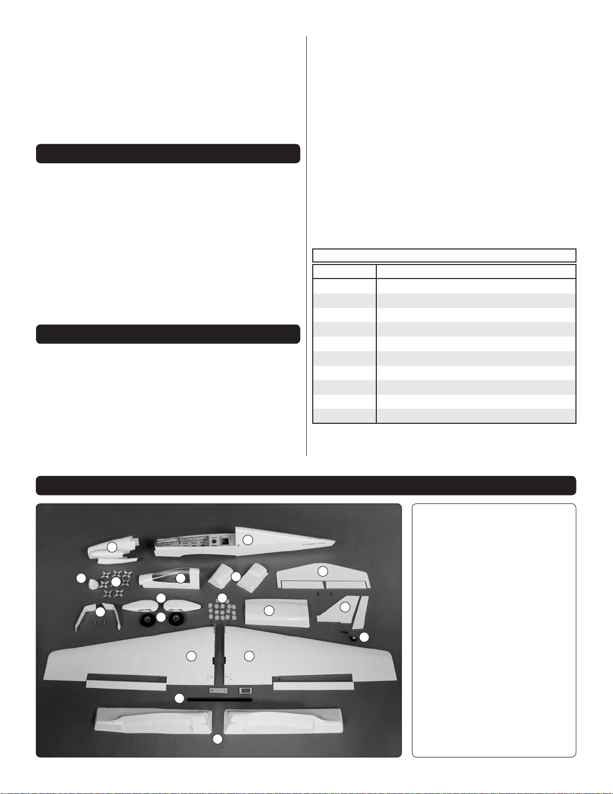
KIT CONTENTS
Kit Contents
1.
6
16
15
10
7
8
9
2
12
13
1
14
17
11
3
4
5
18
5
Fuselage
2.
Left Wing & Aileron
3.
Right Wing & Aileron
4.
Horiz. Stabilizer & Elevators
5.
Vertical Fin & Rudder
6.
Cowl
7.
Canopy
8.
Wheel Pants
9.
Main Wheels
10.
Main Landing Gear
11.
Belly Pan
12.
Wing Tube
13.
Wing Fairings
14.
Cockpit Floor
15.
Motor Spacers
16.
Spinner
17.
CA Hinges
18.
Tail Wheel Assembly
Page 6
PREPARATIONS
1. If you have not done so already, remove the major
❏
parts of the kit from the box and inspect for damage. If any
parts are damaged or missing, contact Product Support at
the address or telephone number listed in the “Kit Inspection”
section on page 5.
2. Remove the tape and separate all the control surfaces.
❏
Use a covering iron with a covering sock on high heat to tighten
the covering if necessary. Apply pressure over sheeted areas
to thoroughly bond the covering to the wood.
ASSEMBLE THE MODEL
Build the Wing
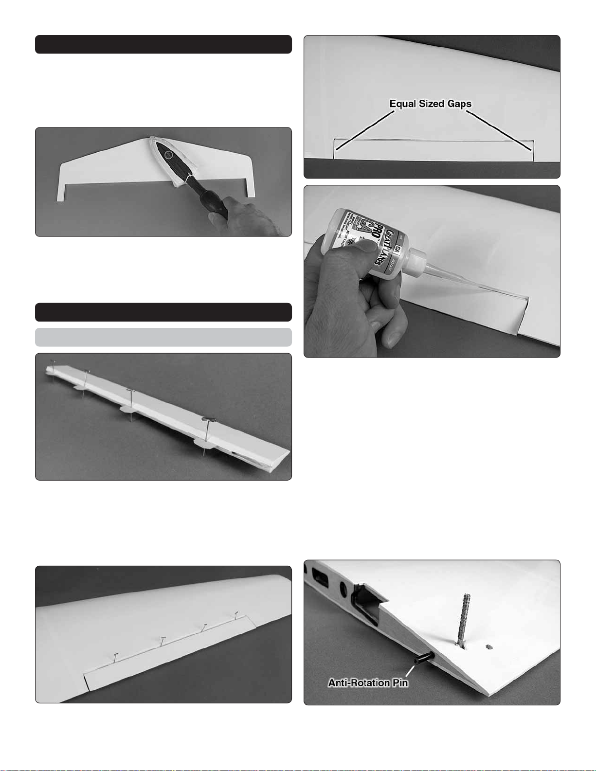
1. Each aileron requires four CA hinges. Use T-pins or
❏
something similar and push one through the center of each
CA hinge. The pins will keep the hinges centered between
the wing panels and ailerons. Insert the hinges into the precut slots in the ailerons as shown. If any hinges are diffi cult
to install, use a hobby knife to enlarge the slot as necessary.
3. When satisfi ed with the fi t, remove the ailerons from the
❏
wings. Clean the ends of the torque rods with a paper towel
dampened with denatured alcohol. Mix up a small amount of
epoxy (6 minute is fi ne but work quickly to glue both aileron
torque rods before the epoxy hardens) and apply a light coating
to the ends of the torque rods. Reinstall the ailerons onto the
wings. Wipe away any excess epoxy that squeezes out of the
torque rod holes. Remove the pins from the hinges and center
the ailerons on the wings, making the gap at each end an
equal length. Push the ailerons up against the trailing edge
of the wing snugging them up. Defl ect the ailerons down and
apply 6 drops of thin CA to the center of each hinge allowing
it to wick into the hinge material. Flip the wings over and apply
6 more drops of CA to the other side of the hinges. When the
CA has hardened, pull on each aileron to confi rm they are
securely glued in place.
2. Test fi t the ailerons onto the wing panels. The metal
❏
torque rods will fi t into the holes pre-drilled in the ailerons.
4. Glue the carbon anti-rotation pin halfway into one of
❏
the wing panels.
6
Page 7
5. Test fi t the wing panels together with the wing tube. The
❏
root ribs of the wing panels should fi t fl at against each other.
If not, lightly sand them as necessary until they do.
You can tape the wing panels together while the epoxy hardens.
The panels can also be held together with spring clamps at
the root tab. Slide the 4x30mm wing bolts through the wing
bolt holes and wrap rubber bands around them to draw the
aft end of the panels together. Ensure that the edges of the
tabs at the leading edge of the panels are fl ush with each
other. Allow the epoxy to cure undisturbed.
6. When satisfi ed with the fi t, mix up 1/4 oz [7cc] of 30-minute
❏
epoxy. Coat one half of the wing joiner tube and insert it into
one of the panels. Coat the root rib of both panels and the
exposed halves of the joiner tube and anti-rotation pin. Slide
the wing panels together and wipe away any excess epoxy.
7. Draw a center line onto the plywood wing bolt plate. Use
❏
a razor saw or hobby knife to make a shallow cut along the
center line. This will allow the plate to bend over the dihedral
angle of the wing.
7
Page 8
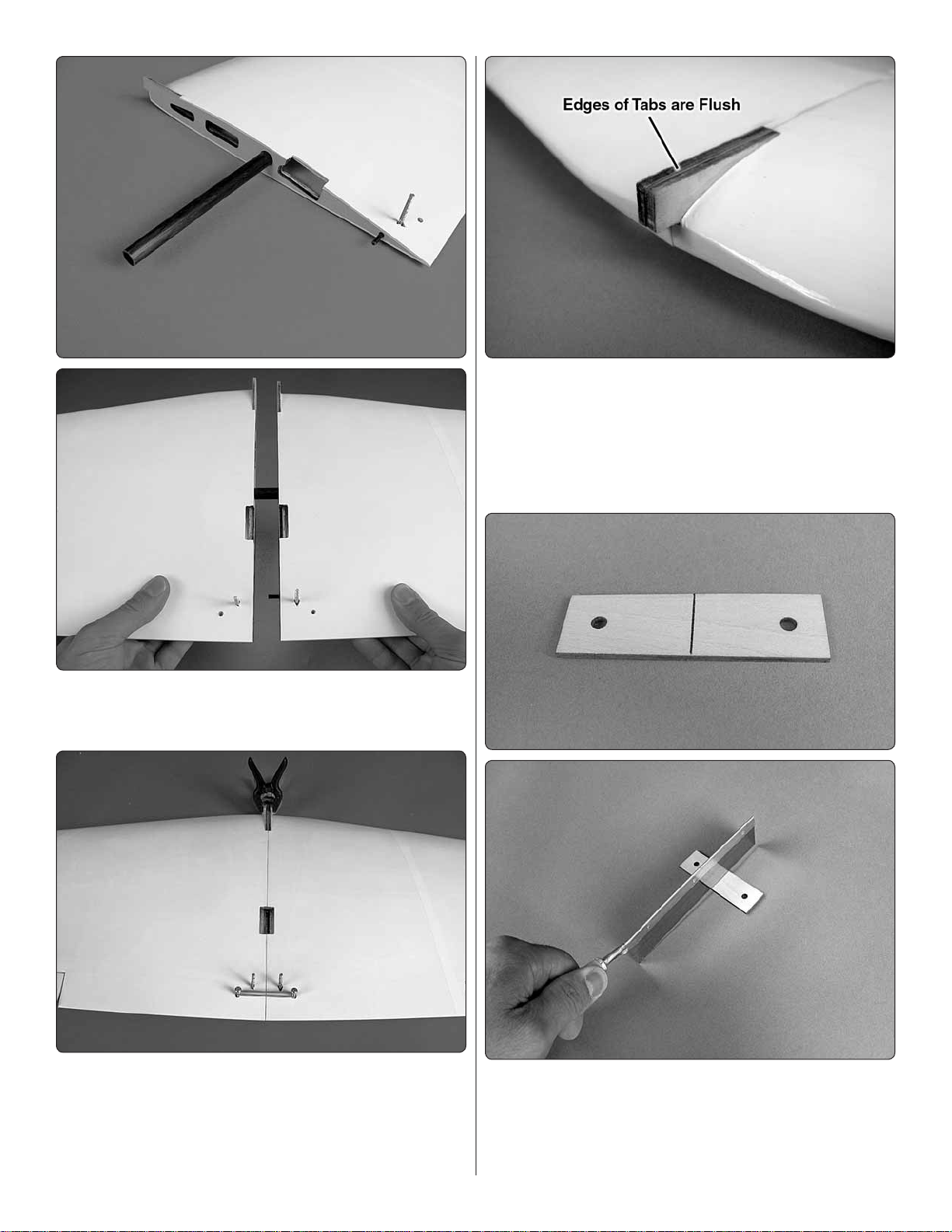
HOW TO CUT COVERING FROM BALSA
Use a soldering iron to cut the covering from the area
beneath the wing bolt plate. The tip of the soldering iron
doesn’t have to be sharp, but a fi ne tip does work best.
Allow the iron to heat fully.
Use a straightedge to guide the soldering iron at a rate that
will just melt the covering and not burn into the wood. The
hotter the soldering iron, the faster it must travel to melt a
fi ne cut. Peel off the covering.
8. Align the holes in the wing bolt plate with the wing bolt
❏
holes in the wing and use a felt-tip pen to trace around the
plate onto the wing.
9. Use a sharp hobby knife or follow the expert tip below, to
❏
remove the covering 1/16" [1.6mm] inside the lines you drew.
Use denatured alcohol to wipe away the lines. Avoid getting
any glue into the exposed holes beneath the covering.
10. Glue the wing bolt plate to the wing being sure that
❏
the holes in the plate are aligned with the holes in the wing.
8
Page 9
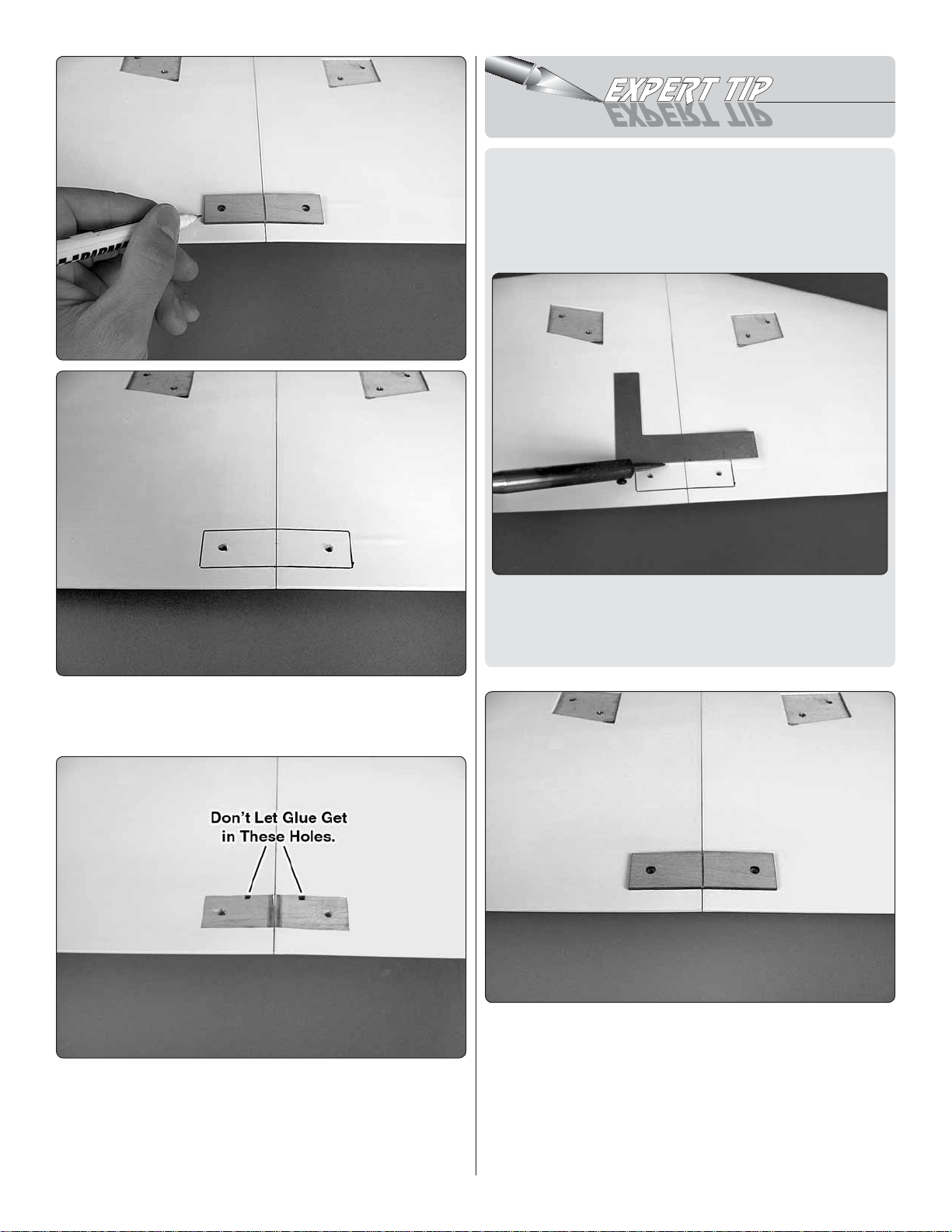
11. As you did with the wing bolt plate, remove the covering
Cut Off
Unused Arms
5/64" [2mm]
17/32" [13.5mm]
❏
and glue the aileron servo tray over the servo bay in the wing.
it and rotate it 90 degrees and re-install it. Repeat this until
you fi nd which way the servo arm fi ts best onto the servo.
Make note of its orientation, remove it, and cut off the two
unused arms as shown in the picture. Because the aileron
pushrods will connect to the holes 17/32" [13.5mm] from
the center of the servo arm, cut off the excess arm length
beyond these holes. Enlarge those holes with a 5/64" [2mm]
drill bit. Install the arm on the servo and secure it with the
servo arm screw.
12. Install the rubber grommets and eyelets included with
❏
your servo hardware. Mount the servo as shown. Drill 1/16"
[1.6mm] holes through the servo tray to mount the aileron servo.
Remove the servo and thread a servo mounting screw into
each hole and then remove it. Apply a drop or two of thin CA
glue to each hole to harden the surrounding wood. When the
CA has hardened, install the servo with the servo mounting
screws included with the servo.
13. Electronically center the aileron servo using your radio
❏
system. Mount a four-armed servo arm onto the aileron servo.
If the servo arm does not fi t “square” to the servo case, remove
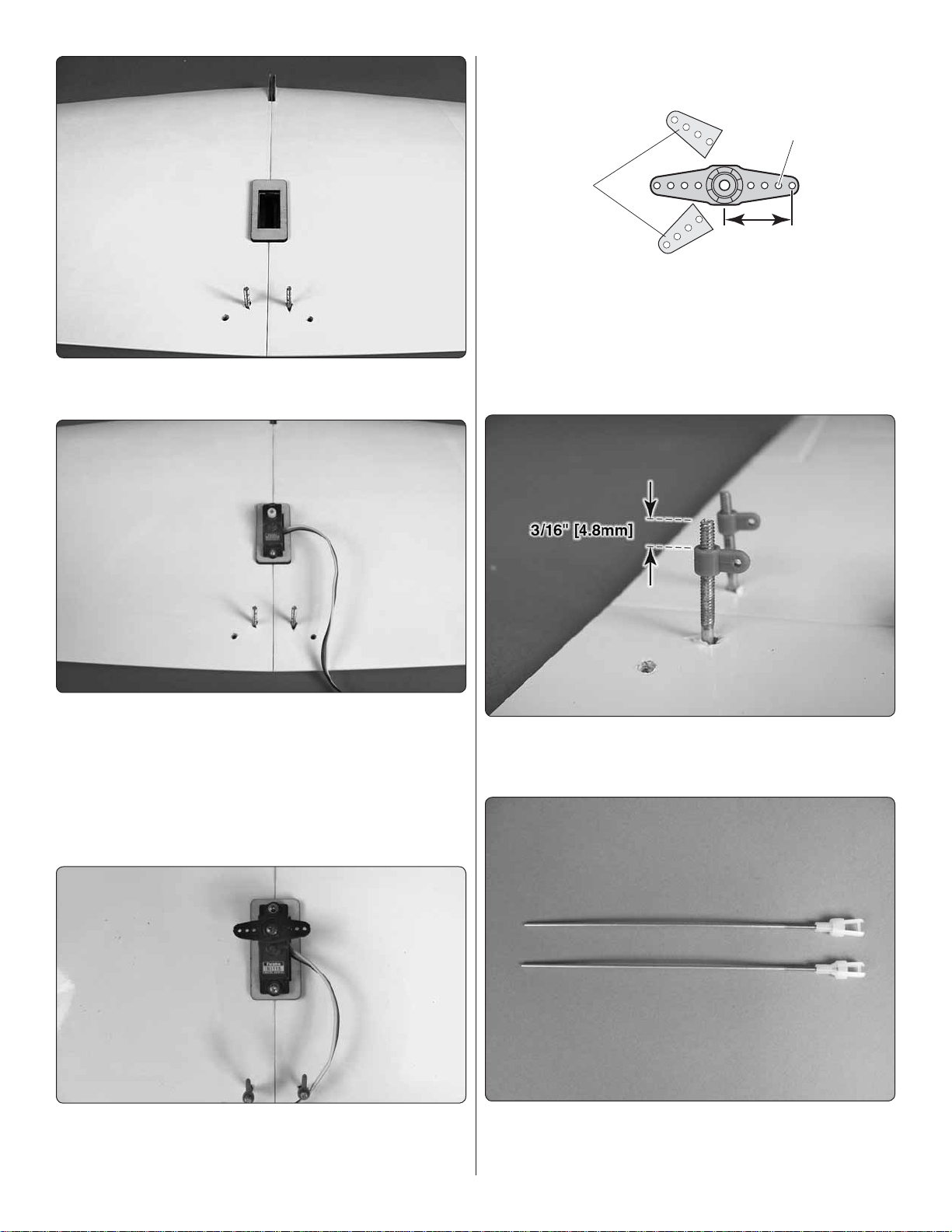
14. Thread a nylon torque rod horn onto each torque rod.
❏
The horns should be positioned 3/16" [4.8mm] from the ends
of the rods.
15. Thread a nylon clevis onto each 2x90mm pushrod
❏
wire 20 complete turns. Slide a silicone clevis onto the base
of each clevis.
9
Page 10

Pushrod Wire
Servo Arm
1/4" [6.4 mm]
FasLink
Assemble the Tail Section
1. Temporarily mount the wing onto the fuselage using two
❏
4x30mm screws and two 4mm fl at washers.
16. Use tape or small spring clamps to hold the ailerons
❏
in the neutral position. Connect the clevises on the pushrods
to the torque rod horns. Mark the pushrods where they cross
the outer holes of the aileron servo arm. Make a 90 degree
bend at the marks on the pushrods and cut off the excess
pushrod 1/4" [6.4mm] beyond the bend. Attach the pushrods
to the servo arm using two FasLinks.
Thread the clevis up or down on the pushrod as necessary to
center the ailerons with the servo arm centered.
2. Slide the horizontal stabilizer into the stab slot and center
❏
it left and right. Stand back approximately 10’ [3m] and view
the model from behind. Confi rm that the wing and stab are
parallel. If not, remove the stab and lightly sand the slot until
the two align symmetrically. Measure the distance between
the wing tips and stab tips and make any adjustments to make
the measurements equal.
10
Page 11

3. When satisfi ed with its position, use a felt-tip pen to
❏
trace around the fuselage onto the stab. Remove the stab
and cut away the covering 1/16" [1.6mm] inside the lines you
drew. Wipe away the lines with a paper towel dampened with
denatured alcohol.
4. Check the fi t of the elevator joiner wire into the elevator
❏
halves. Lay them on a fl at surface. If the two elevator halves
do not lay fl at, make adjustments to the wire until they do.
5. Hinge the elevator halves onto the stabilizer just as
❏
you did with the ailerons. Ensure that the elevators are
equally spaced between the stab ends. The elevators
should both be centered. Pull on elevators to be sure
they are securely attached.
5. Clean the ends of the elevator joiner wire with denatured
❏
alcohol. Insert the joiner wire into the aft end of the stab slot.
Mix up a batch of epoxy (30-minute is recommended to allow
you the added working time) and coat the exposed wood (top
and bottom) of the stab. While holding the joiner wire back and
out of the way, slide the stab back into the slot aligning it with
the wing and centering it left and right. Clean up any excess
epoxy with denatured alcohol. If necessary, add weight to the
high side of the stab while the epoxy is curing to ensure that
the wing and stab remain parallel. On the center stab, check
the alignment and use medium CA.
6. Insert the vertical fi n into the slot in the fuselage. Trace
❏
around the fuselage onto the fi n. Remove the covering 1/16"
[1.6mm] below your lines. Wipe away the lines with alcohol
and epoxy the fi n into the slot. View the plane from behind
and confi rm that the fi n is square with the stab. If not, use
some masking tape to pull it square while the epoxy is curing.
11
Page 12

7. The tail wheel is provided to you pre-assembled from
❏
the factory. If you choose to remove the wheel to reduce drag
the axle can be bent vertically to act as a tail skid.
8. Temporarily insert the tail wheel wire into the hole in the
❏
leading edge of the rudder.
9. Hold the rudder up against the rudder hinge line on the
❏
fuselage. Draw a line onto the fuselage that matches the angle
of the nylon tail wheel hinge point.
10. Drill a 9/64" [3.6mm] hole for the tail wheel hinge point.
❏
Be sure that the hole you are drilling is centered in the hinge
line and matches the angle of the hinge point. A smaller pilot
hole is recommended.
12
Page 13

11. Prepare three CA hinges with T-pins and insert them
❏
into the rudder (we recommend test fi tting the rudder and tail
wheel wire onto the fuselage without glue before completing
this step). Clean the section of the tail wheel wire that fi ts
into the rudder with denatured alcohol. Apply a drop or two
of household oil to the tail wheel hinge point bearing. Mix up
a small batch of epoxy and use a toothpick to coat the inside
of the hole in the rudder as well as the hole you drilled in the
previous step. Apply a very light coating of epoxy onto the tail
wheel hinge point. Insert the tail wheel wire into the rudder
and the hinges and hinge point into the fuselage. Wipe away
any excess epoxy with alcohol. Remove the T-pins from the
hinges and apply 6 to 7 drops of thin CA to both sides of each
hinge. Tug on the rudder to ensure that it is securely hinged.
13. Insert a 21-5/8" [550mm] long pushrod into each of the
❏
tail pushrod tubes. Gently push them against the covering that
is over the exit slots. This will show you exactly where you need
to trim away the covering from the exit slots. Trim the covering.
Hinge Line Hinge Line
Correct Incorrect
12. Mount the tail surface servos in the orientation shown.
❏
Electronically center the servos using your radio system.
Determine the best fi t of your servo horns and cut away the
unused arms.
14. Thread a clevis onto a pushrod. Connect the clevis to
❏
the outer hole of a control horn and insert the pushrod into
the elevator pushrod tube. Align the holes in the control horn
over the elevator hinge line and mark the location for the
mounting holes.
13
Page 14

15. Drill 5/64" [2mm] holes at the marks you made. Install
Pushrod Wire
Servo Arm
1/4" [6.4 mm]
FasLink
❏
the control horn using two 2x12mm machine screws and a
control horn backplate.
Remove the pushrod from the plane. Bend the pushrod 90
degrees at your mark and cut off the excess pushrod 1/4"
[6.4mm] beyond the bend. Enlarge the inner hole of the pushrod
to 5/64" [2mm]. Remove the clevis from the pushrod and insert
the pushrod back into the pushrod tube. Reinstall the clevis
onto the pushrod. Connect the bend in the pushrod into the
inner hole of the servo arm and secure it using a FasLink.
16. Use a small spring clamp or tape to hold the elevators
❏
in the neutral position.
17. Mark the pushrod where it crosses the innermost hole
❏
in the elevator servo arm.
Connect the clevis to the outer hole of the elevator control
horn. Remove the spring clamp and check the elevator servo
one more time with your radio system. Make any adjustments
to the clevis position on the pushrod to ensure the elevators
are centered with the servo centered. When satisfi ed, slide
the clevis retainer toward the aft end of the clevis.
18. The rudder pushrod is installed in the same way as
❏
the elevator pushrod.
14
Page 15

However, the clevis should connect to the second hole from
the base of the control horn and the 90 degree bend should
connect to the hole that is 1/2" [13mm] from the center of the
servo arm. A slight bend in the pushrod at the aft end will
prevent the pushrod from binding in the pushrod tube.
Install the Power System
Power 25 1250kV motor (“+” marks). Other motors may not
align with these marks and will require you to use the centering
lines on the fi rewall to mark the mounting hole locations for
your motor.
3. 3x35mm screws are included for accommodating motors
❏
requiring all eight motor spacers. If you are using less than eight
spacers, the screws can be cut shorter but this may not be a
necessary step. If you need to cut the screws, thread a blind
nut onto each screw before cutting them. Removing the blind
nut after the cut is made will straighten any damaged threads.
1. The Proud Bird includes eight plywood motor spacers
❏
to accommodate different length motors. The recommended
O.S. .25 motor (OMA-3820-1200) requires the use of three
of these spacers to set the face of the prop adapter at the
correct length of 2-3/4" [70mm] from the fi rewall. The E-Flite
Power 25 1250kV motor does not need any spacers. Use
the spacers to properly space different model motors to the
correct distance from the fi rewall.
2. The firewall has mounting hole locations for the
❏
recommended O.S. .25 motor (“O” marks) and the E-Flite
4. Drill 5/32" [4mm] at the marks that match the motor
❏
mounting hole pattern of your motor. We suggest starting with
small pilot holes to ensure accuracy. Use a motor mounting
screw and fl at washer to draw 3mm blind nuts tightly into the
holes you drilled. Apply a drop of glue to the back of each
blind nut to secure them in place.
5. Mount your motor using the four 3x35mm motor mount
❏
screws, four 3mm fl at washers and thread locking compound.
15
Page 16

6. The recommended O.S. motor includes 3mm female bullet
❏
connectors which must be soldered onto the recommended
Castle Ice 75A ESC. This speed control will also require you
to solder a battery connector to the battery leads. If you are
using the recommended battery, you will need W.S. Deans
Male Ultra Plug (WSDM1302).
8. Use a piece of self-adhesive hook and loop material or
❏
make a strap from non-adhesive hook and loop material to
secure the receiver in the location shown.
9. Cut the included 2" [51mm] piece of plastic tubing into
❏
two equal pieces. Glue the pieces to hold the 2.4GHz receiver
antennas in the orientation described in your radio manual.
7. Make a 6" [152mm] long strap to hold the ESC in place
❏
from the included hook and loop material by cutting a length
and overlapping the mating ends by 1/2" [13mm]. Connect
the ESC to the motor and route the receiver lead through
the hole in the fuselage former. A 6" [152mm] servo lead
extension is required. Be sure to use tape, heat shrink tubing
or a special clip made for securing servo lead extension
connectors together.
10. Coat the center of the battery tray with a thin coating
❏
of epoxy to improve the adhesion of the self-adhesive hook
and loop material. Medium or thick CA glue will also work.
Allow the glue to harden completely before attaching pieces
of the hook side from self-adhesive hook and loop material.
16
Page 17

Assemble & Install the Landing Gear
2. Mount the landing gear onto the wings using four 4x12mm
❏
fl at head machine screws and thread locking compound.
Install the Wing Fairings,
Belly Pan & Cockpit Floor
1. Cut out the wing
❏
fairings along the cut
lines. Curved canopy
scissors work well for
this task (HCAR0667).
1. Apply a drop or two of household oil to the main wheel
❏
axles and thread locking compound to each axle nut. Fit an
axle through a landing gear leg and partially into the wheel
pant that fi ts onto that gear leg. Use a slender pair of needlenose pliers to hold the axle nut. Put a main wheel into the
wheel pant, fi t the axle nut between the wheel and the pant
aligned with the axle hole and slide the axle through the nut
and through the wheel hub into the plywood disk glued to
the other side of the pant. Holding the axle nut with pliers,
tighten the axle. Repeat this step for the other landing gear
leg. Use threadlocker.
2. The fairings are molded to fi t on the sides of the wing
❏
saddle and on the formers at the fore and aft ends of the
saddle. Attach the wing. Test fi t the fairings in place and make
any adjustments necessary until you are satisfi ed with the fi t.
17
Page 18

Use 220 grit sandpaper to smooth out the edges. The fairings
can be glued on with canopy glue or CA glue. We recommend
CA glue to avoid the drying time and masking tape required for
canopy glue. To glue the fairings on with CA, apply a drop of
medium or thick CA approximately every inch along the inside
of the fairings where they fi t onto the wing saddle edges and
fore and aft formers. Press and hold them into place until the
CA glue tacks up. Flip the plane over and use a small fl athead
screwdriver to carefully pry the fairings away from the fuse
sides and apply additional drops of CA until the fairings are
thoroughly glued in place.
its fi t. Don’t allow the belly pan to cover any part of the landing
gear bases. That may make them diffi cult to remove in the
event they need to be repaired or replaced. Glue the belly pan
to the wing. Take care not to glue the wing to the fuselage!
3. Trim the belly pan along the
❏
cut lines. Make holes for the wing
screws. Their location is marked
with indentations. A body reamer
works well for this task as it will
make perfectly circular shaped
holes without tearing the material
(DTXR1158).
5. Trim the aft cockpit fl oor along the cut lines and test fi t
❏
it in place. Before gluing this piece in place, confi rm that your
receiver antennas are properly placed, your receiver is bound
to your transmitter, your tail servos and ESC are connected
and you have a 6" [152mm] servo extension plugged into
your aileron channel. Gluing the aft cockpit fl oor in place will
provide only limited access to your receiver. We suggest using
canopy glue sparingly or taping the fl oor in place in case you
need to remove the fl oor in the future.
4. Test fi t the belly pan in place and make any additional
❏
trimming and sanding necessary until you are satisfi ed with
6. Trim the forward cockpit fl oor along the cut lines.
❏
18
Page 19

7. Test fi t the forward cockpit fl oor in place. The back end
❏
of the forward fl oor fi ts underneath the aft cockpit fl oor. The
forward cockpit fl oor is meant to be removable to provide you
access to the battery. How you set it up to be removable is
up to you. We used some scrap material from trimming the
parts. To do this, choose a length of material that has a 90
degree bend and cut two strips approximately 1/2" [13mm]
long and 1/8" [3.2mm] wide with the 90 degree bend going
down the lengths of the strips. The crease in the strips will
help keep them rigid. With the forward cockpit fl oor in place,
glue the strips to the cockpit sides as shown, overlapping the
front edges of the fl oor piece. To remove the forward cockpit
fl oor, simply squeeze together the two front sides to unhook
the piece from the strips.
Finish the Model
1. Cut strips of card stock or something similar approximately
❏
4" [102mm] long and tape the aft ends of the strips to the
fuselage in the location shown (one on each side of the
fuselage). Use the measurements shown in the picture and
mark the pieces of card stock for the cowl mounting screws.
Use a T-pin to make small holes at your marks in the card stock.
19
Page 20

4. Use CA to glue a
❏
magnet into each plywood
disk. Allow the glue to harden
completely before continuing
to the next step.
2. Slide the cowl onto the fuselage. Fit the spinner backplate
❏
onto the prop adapter (if you are using the recommended
O.S. motor you will need to enlarge the hole in the backplate
to 5.0mm). Position the cowl so that the front of the cowl is
centered behind the backplate and there is a 5/64" [2 mm]
gap between the cowl and backplate. Use a felt-tip pen to
make marks through the holes in the card stock onto the cowl.
3. Drill 1/16" [1.6mm] holes at your marks through the cowl,
❏
through the wing fairings and through the fuselage sides.
Remove the cowl from the fuselage. Thread a 2.3 x 10mm
washer head screw into each hole in the fuselage and back
it out. Apply a drop of thin CA to each hole and let the glue
harden. Enlarge the holes in the cowl to 3/32" [2.4mm]. Install
the cowl using four 2.3 x 10mm washer head screws.
5. Magnetically attach the disks from the previous step to
❏
the magnets in the fuselage. Without glue, test fi t the canopy
onto the fuselage by fi tting the forward end underneath the cowl.
6. Apply a thin fi lm of medium or thick CA glue onto the center
❏
of each magnet that is inside the plywood disks. Apply the glue
20
Page 21

sparingly as you do not want it to run and inadvertently
FULL THROTTLE
RUDDER
MOVES RIGHT
ELEVATOR MOVES DOWN
RIGHT AILERON MOVES UP
LEFT AILERON MOVES DOWN
4-Channel Radio Set Up (Standard Mode 2)
glue the disks to the fuselage. We recommend taping some
non-stick material around the magnets such as wax paper to
prevent gluing the canopy to the fuselage. Put the canopy in
place and press the canopy against the magnets. Hold it there
for a minute or two allowing time for the glue to tack. When
the glue has completely hardened, test the operation of the
canopy by pulling the magnets (which are now glued to the
canopy) outward to release the canopy from the fuselage.
3. Position decal on the model where desired. Holding the
❏
decal down, use a paper towel to wipe most of the water away.
4. Use a piece of soft balsa or something similar to squeegee
❏
remaining water from under the decal. Apply the rest of the
decals the same way.
GET THE MODEL READY TO FLY
Check the Control Directions
1. Turn on the transmitter and receiver and center the trims.
❏
If necessary, remove the servo arms from the servos and
reposition them so they are centered. Reinstall the screws
that hold on the servo arms.
2. With the transmitter and receiver still on, check all the
❏
control surfaces to see if they are centered. If necessary, adjust
the clevises on the pushrods to center the control surfaces.
7. Install the spinner backplate followed by the prop, prop
❏
washer, prop nut, and spinner cone.
8. You have now completed the assembly of the Proud
❏
Bird ARF!
Apply the Decals
1. Use scissors or a sharp hobby knife to cut the decals
❏
from the sheet.
2. Be certain the model is clean and free from oily fi ngerprints
❏
and dust. Prepare a dishpan or small bucket with a mixture
of liquid dish soap and warm water—about one teaspoon of
soap per gallon of water. Submerse the decal in the soap and
water and peel off the paper backing. Note: Even though the
decals have a “sticky-back” and are not the water transfer type,
submersing them in soap & water allows accurate positioning
and reduces air bubbles underneath.
3. Make certain that the control surfaces and the throttle
❏
respond in the correct direction as shown in the diagram. If any
of the controls respond in the wrong direction, use the servo
reversing in the transmitter to reverse the servos connected to
those controls. Be certain the control surfaces have remained
centered. Adjust if necessary.
Set the Control Throws
To ensure a successful fi rst fl ight, set up your Proud Bird
according to the control throws specifi ed in this manual. The
throws have been determined through actual fl ight testing
and accurate record-keeping allowing the model to perform
in the manner in which it was intended. If, after you have
become accustomed to the way the Proud Bird fl ies, you
would like to change the throws to suit your taste, that is
fi ne. However, too much control throw could make the model
too responsive and diffi cult to control, so remember, “more
is not always better.”
21
Page 22

NOTE: The throws are measured at the widest part of the
elevators, rudder and ailerons.
These are the recommended control surface throws:
1. Use a box or something similar to prop up the bottom of
❏
the fuselage so the horizontal stabilizer and wing will be level.
Measure the high rate elevator throw fi rst…
2. Hold a ruler vertically on your workbench against the
❏
widest part (front to back) of the trailing edge of the elevator.
Note the measurement on the ruler.
(Move the
ruler forward)
LOW RATE
Up & Down
HIGH RATE
Up & Down
ELEVATOR
1/8" [3mm] 5°
Right & Left
3/16” [5 mm] 7°
Right & Left
RUDDER
AILERONS
1/2" [13mm] 18°
Up & Down
1/4" [6mm] 11°
3/4" [19 mm] 27°
Up & Down
3/8" [10 mm] 17°
ESC Setup
If you have installed the recommended ESC and brushless
motor, then we suggest setting your motor timing to HIGH (10).
Also, we recommend setting the cutoff voltage to AUTO-LIPO
and 3.0 VOLTS/CELL.
Balance the Model (C.G.)
More than any other factor, the C.G. (center of gravity/
balance point) can have the greatest effect on how a model
fl ies and could determine whether or not your fi rst fl ight will
be successful. If you value your model and wish to enjoy it
for many fl ights, DO NOT OVERLOOK THIS IMPORTANT
PROCEDURE. A model that is not properly balanced may
be unstable and possibly unfl yable.
3. Move the elevator up with your transmitter and move the
❏
ruler forward so it will remain contacting the trailing edge. The
distance the elevator moves up from center is the “up” elevator
throw. Measure the down elevator throw the same way.
4. Measure and set the low rate elevator throws and the
❏
high and low rate throws for the rest of the control surfaces
the same way.
If your radio does not have dual rates, we recommend setting
the throws at the low rate settings for at least your fi rst couple
of fl ights.
At this stage the model should be in ready-to-fl y condition with
all of the components in place including the complete radio
system, battery, propeller, spinner and pilot (not included).
If you haven’t already done so, apply the loop side of selfadhesive hook and loop material and apply it to the battery.
Fit the battery on the center of the tray.
1. If using a Great Planes C.G. Machine, set the rulers to
❏
3-7/8" [98mm]. If not using a C.G. Machine, use a fi ne-point
felt tip pen to mark lines on the top of wing on both sides of
the fuselage 3-7/8" [98mm] back from the leading edge. Apply
narrow (1/16" [2mm]) strips of tape over the lines so you will
be able to feel them when lifting the model with your fi ngers.
This is where your model should balance for the fi rst
fl ights. Later, you may experiment by shifting the C.G. 1/8"
[3.2mm] forward or 1/8" [3.2mm] back to change the fl ying
characteristics. Moving the C.G. forward will improve the
smoothness and stability, but the model will then be less
aerobatic (which may be fi ne for less-experienced pilots).
Moving the C.G. aft makes the model more maneuverable
and aerobatic for experienced pilots. In any case, start at
the recommended balance point and do not at any time
balance the model outside the specifi ed range.
22
Page 23

2. With the wing attached to the fuselage, all parts of the
❏
model installed (ready to fl y) and an empty fuel tank, place
the model upside-down on a Great Planes CG Machine, or
lift it upside-down at the balance point you marked.
3. If the tail drops, the model is “tail heavy.” Move the battery
❏
pack forward to get the model to balance. If the nose drops,
the model is “nose heavy.” Move the battery pack aft. If the
battery cannot be moved far enough to bring the model to
balance, or if additional weight is still required, nose weight
may be easily added by using Great Planes “stick-on” lead
(GPMQ4485). To fi nd out how much weight is required, place
incrementally increasing amounts of weight on the bottom
of the fuselage over the location where it would be mounted
inside until the model balances. A good place to add stick-
on nose weight is to the fi rewall. Do not attach weight to the
cowl—this will cause the mounting screws to open up the
holes in the cowl. Once you have determined the amount of
weight required, it can be permanently attached. If required,
tail weight may be added by cutting open the bottom of the
fuse and gluing it permanently inside.
Note: Over time, the adhesive on the stick-on lead weight
may fail and cause the weight to fall off. Do not rely on the
adhesive alone to secure the weight. Instead, permanently
attach the weight with glue or screws.
4. IMPORTANT: If you found it necessary to add any weight,
❏
recheck the C.G. after the weight has been installed.
Balance the Model Laterally
1. With the wing level, have an assistant help you lift the
❏
model by the engine propeller shaft and the bottom of the
fuse under the TE of the fi n. Do this several times.
2. If one wing always drops when you lift the model, it means
❏
that side is heavy. Balance the airplane by adding weight to the
other wing tip. An airplane that has been laterally balanced
will track better in loops and other maneuvers.
PREFLIGHT
Identify Your Model
No matter if you fl y at an AMA sanctioned R/C club site or if
you fl y somewhere on your own, you should always have your
name, address, telephone number and AMA number on or
inside your model. It is required at all AMA R/C club fl ying sites
and AMA sanctioned fl ying events. Fill out the identifi cation
tag on the back cover and place it on or inside your model.
Charge the Batteries
Follow the battery charging instructions that came with your
radio control system to charge the batteries. You should always
charge your transmitter battery the night before you go fl ying,
and at other times as recommended by the radio manufacturer.
CAUTION: Unless the instructions that came with your
radio system state differently, the initial charge on new
transmitter and receiver batteries should be done for 15
hours using the slow-charger that came with the radio
system. This will “condition” the batteries so that the next
charge may be done using the fast-charger of your choice.
If the initial charge is done with a fast-charger the batteries
may not reach their full capacity and you may be fl ying with
batteries that are only partially charged.
Balance Propellers
5. Once you have determined the optimum position of the
❏
battery on the battery tray, make a strap from the remaining
hook and loop material and fi t it through the slots in the battery
tray that best match the location of the battery. Mark the
location of the battery. Use the marks to position the battery
on the tray for future fl ights.
Carefully balance your propeller and spare propellers before
you fl y. An unbalanced prop can be the single most signifi cant
cause of vibration that can damage your model. Not only
will engine mounting screws and bolts loosen, possibly with
23
Page 24

disastrous effect, but vibration may also damage your radio
receiver and battery.
We use a Top Flite Precision Magnetic Prop Balancer
(TOPQ5700) in the workshop and keep a Great Planes
Fingertip Prop Balancer (GPMQ5000) in our fl ight box.
2) I will not fl y my model aircraft higher than approximately
400 feet within 3 miles of an airport without notifying the
airport operator. I will give right-of-way and avoid fl ying in the
proximity of full-scale aircraft. Where necessary, an observer
shall be utilized to supervise fl ying to avoid having models fl y
in the proximity of full-scale aircraft.
Ground Check & Range Check
Run the motor on the ground and confi rm that it transitions
smoothly to full power and there is not excessive vibration
(which would indicate a prop that requires balancing). Afterward,
inspect the model closely, making sure all fasteners, pushrods
and connections have remained tight and the hinges are secure.
Always ground check the operational range of your radio
before the fi rst fl ight of the day following the manufacturer’s
instructions that came with your radio. This should be done
once with the motor off and once with the motor running at
various speeds. If the control surfaces do not respond correctly,
do not fl y! Find and correct the problem fi rst. Look for loose
servo connections or broken wires, corroded wires on old
servo connectors, or possibly a problem with the transmitter
or receiver.
MOTOR SAFETY PRECAUTIONS
Failure to follow these safety precautions may result in
severe injury to yourself and others.
● Get help from an experienced pilot when learning to
operate motors.
● Use safety glasses when starting or running motors.
● Do not run the motor in an area of loose gravel or sand;
the propeller may throw such material in your face or eyes.
● Keep your face and body as well as all spectators away
from the plane of rotation of the propeller as you run
the motor.
● Keep these items away from the prop: loose clothing,
shirt sleeves, ties, scarfs, long hair or loose objects such
as pencils or screwdrivers that may fall out of shirt or
jacket pockets into the prop.
● The motor gets hot! Do not touch it during or right after
operation.
AMA SAFETY CODE EXCERPTS
Read and abide by the following excerpts from the Academy
of Model Aeronautics Safety Code. For the complete Safety
Code refer to Model Aviation magazine, the AMA web site or
the Code that came with your AMA license.
General
1) I will not fl y my model aircraft in sanctioned events, air shows,
or model fl ying demonstrations until it has been proven to be
airworthy by having been previously, successfully fl ight tested.
3) Where established, I will abide by the safety rules for the
fl ying site I use, and I will not willfully and deliberately fl y my
models in a careless, reckless and/or dangerous manner.
5) I will not fl y my model unless it is identifi ed with my name
and address or AMA number, on or in the model. Note: This
does not apply to models while being fl own indoors.
7) I will not operate models with pyrotechnics (any device that
explodes, burns, or propels a projectile of any kind).
Radio Control
1) I will have completed a successful radio equipment ground
check before the fi rst fl ight of a new or repaired model.
2) I will not fl y my model aircraft in the presence of spectators
until I become a qualified flier, unless assisted by an
experienced helper.
3) At all fl ying sites a straight or curved line(s) must be
established in front of which all fl ying takes place with the
other side for spectators. Only personnel involved with fl ying
the aircraft are allowed at or in the front of the fl ight line.
Intentional fl ying behind the fl ight line is prohibited.
4) I will operate my model using only radio control frequencies
currently allowed by the Federal Communications Commission.
5) I will not knowingly operate my model within three miles
of any pre-existing fl ying site except in accordance with
the frequency sharing agreement listed [in the complete
AMA Safety Code].
9) Under no circumstances may a pilot or other person touch
a powered model in fl ight; nor should any part of the model
other than the landing gear, intentionally touch the ground,
except while landing.
CHECK LIST
During the last few moments of preparation your mind may
be elsewhere anticipating the excitement of the fi rst fl ight.
Because of this, you may be more likely to overlook certain
checks and procedures that should be performed before the
model is fl own. To help avoid this, a check list is provided to
make sure these important areas are not overlooked. Many
are covered in the instruction manual, so where appropriate,
refer to the manual for complete instructions. Be sure to
check the items off as they are completed (that’s why it’s
called a check list!).
1. Check the C.G. according to the measurements provided
❏
in the manual.
24
Page 25

2. Be certain the battery and receiver are securely mounted
❏
in the fuse. Simply stuffi ng them into place with foam rubber
is not suffi cient.
3. Extend your receiver antenna (if applicable) and make
❏
sure it has a strain relief inside the fuselage to keep tension
off the solder joint inside the receiver.
4. Balance your model laterally as explained in the
❏
instructions.
5. Use threadlocking compound to secure critical fasteners
❏
such as the motor screws, screw-lock pushrod connectors, etc.
6. Add a drop of oil to the axles so the wheels will turn freely.
❏
7. Make sure all hinges are securely glued in place.
❏
8. Reinforce holes for wood screws with thin CA where
❏
appropriate (servo mounting screws, cowl mounting screws,
etc.).
9. Confi rm that all controls operate in the correct direction
❏
and the throws are set up according to the manual.
10. Make sure there are silicone retainers on all the clevises
❏
and that all servo arms are secured to the servos with the
screws included with your radio.
11. Secure connections between servo wires and
❏
Y-connectors or servo extensions, and the connection between
your battery pack and the on/off switch with vinyl tape, heat
shrink tubing or special clips suitable for that purpose.
12. Make sure any servo extension cords you may have used
❏
do not interfere with other systems (servo arms, pushrods, etc.).
13. Balance your propeller (and spare propellers).
❏
14. Tighten the propeller nut and spinner.
❏
15. Place your name, address, AMA number and telephone
❏
number on or inside your model.
16. If you wish to photograph your model, do so before
❏
your fi rst fl ight.
17. Range check your radio when you get to the fl ying fi eld.
❏
Identify which surface fl uttered (so the problem may be
resolved) by checking all the servo grommets for deterioration
or signs of vibration. Make certain all pushrod linkages are
secure and free of play. If it fl uttered once, under similar
circumstances it will probably fl utter again unless the problem
is fi xed. Some things which can cause fl utter are; Excessive
hinge gap; Not mounting control horns solidly; Poor fi t of
clevis pin in horn; Side-play of wire pushrods caused by
large bends; Excessive free play in servo gears; Insecure
servo mounting; and one of the most prevalent causes of
fl utter; Flying an over-powered model at excessive speeds.
Takeoff
Before you get ready to take off, see how the model handles
on the ground by doing a few practice runs at low speeds on
the runway. Hold “up” elevator to keep the tail wheel on the
ground. If necessary, adjust the tail wheel so the model will
roll straight down the runway. If you need to calm your nerves
before the maiden fl ight, bring the model back into the pits.
Top off the charge in your pack, then check all fasteners and
control linkages for peace of mind.
Remember to take off into the wind. When you’re ready, point
the model straight down the runway, hold a bit of up elevator
to keep the tail on the ground to maintain tail wheel steering,
then gradually advance the throttle. As the model gains
speed decrease up elevator allowing the tail to come off the
ground. One of the most important things to remember with
a tail dragger is to always be ready to apply right rudder to
counteract engine torque. Gain as much speed as your runway
and fl ying site will practically allow before gently applying up
elevator, lifting the model into the air. At this moment it is likely
that you will need to apply more right rudder to counteract
engine torque. Be smooth on the elevator stick, allowing the
model to establish a gentle climb to a safe altitude before
turning into the traffi c pattern.
Flight
FLYING
The Proud Bird is a great-fl ying model that fl ies smoothly and
predictably. The Proud Bird does not, however, possess the
self-recovery characteristics of a primary R/C trainer and
should be fl own only by experienced R/C pilots.
CAUTION: (THIS APPLIES TO ALL R/C AIRPLANES): If,
while fl ying, you notice an alarming or unusual sound such
as a low-pitched “buzz,” this may indicate control surface
fl utter. Flutter occurs when a control surface (such as an
aileron or elevator) or a fl ying surface (such as a wing or
stab) rapidly vibrates up and down (thus causing the noise).
In extreme cases, if not detected immediately, fl utter can
actually cause the control surface to detach or the fl ying
surface to fail, thus causing loss of control followed by an
impending crash. The best thing to do when fl utter is detected
is to slow the model immediately by reducing power, then
land as soon as safely possible.
For reassurance and to keep an eye on other traffi c, it is a
good idea to have an assistant on the fl ight line with you. Tell
him to remind you to throttle back once the plane gets to a
comfortable altitude. While full throttle is usually desirable for
takeoff, most models fl y more smoothly at reduced speeds.
Take it easy with the Proud Bird for the fi rst few fl ights, gradually
getting acquainted with it as you gain confi dence. Adjust the
trims to maintain straight and level fl ight. After fl ying around for
a while, and while still at a safe altitude with plenty of battery
charge, practice slow fl ight and execute practice landing
approaches by reducing the throttle to see how the model
handles at slower speeds. Add power to see how she climbs
as well. Continue to fl y around, executing various maneuvers
and making mental notes (or having your assistant write them
down) of what trim or C.G. changes may be required to fi ne
tune the model so it fl ies the way you like. Mind your battery
charge, but use this fi rst fl ight to become familiar with your
model before landing.
25
Page 26

Landing
To initiate a landing approach, lower the throttle while on the
downwind leg. Allow the nose of the model to pitch downward
to gradually bleed off altitude. Continue to lose altitude, but
maintain airspeed by keeping the nose down as you turn onto
the crosswind leg. Make your fi nal turn toward the runway (into
the wind) keeping the nose down to maintain airspeed and
control. Level the attitude when the model reaches the runway
threshold, modulating the throttle as necessary to maintain
your glide path and airspeed. If you are going to overshoot,
smoothly advance the throttle (always ready on the right rudder
to counteract torque) and climb out to make another attempt.
When you’re ready to make your landing fl are and the model
is a foot or so off the deck, smoothly increase up elevator until
it gently touches down. Once the model is on the runway and
has lost fl ying speed, hold up elevator to place the tail on the
ground, regaining tail wheel control.
One fi nal note about fl ying your model. Have a goal or fl ight
plan in mind for every fl ight. This can be learning a new
maneuver(s), improving a maneuver(s) you already know,
or learning how the model behaves in certain conditions
(such as on high or low rates). This is not necessarily to
improve your skills (though it is never a bad idea!), but more
importantly so you do not surprise yourself by impulsively
attempting a maneuver and suddenly fi nding that you’ve run
out of time, altitude or airspeed. Every maneuver should be
deliberate, not impulsive. For example, if you’re going to do a
loop, check your altitude, mind the wind direction (anticipating
rudder corrections that will be required to maintain heading),
remember to throttle back at the top, and make certain you
are on the desired rates (high/low rates). A fl ight plan greatly
reduces the chances of crashing your model just because
of poor planning and impulsive moves. Remember to think.
Have a ball! But always stay in control
and fl y in a safe manner.
GOOD LUCK AND GREAT FLYING!
TRIMMING THE PROUD BIRD
FOR RACING
“The NMPRA developed the Electric Formula 1 class to fi ll a
need for a fun racing class that would be a great way for RC
pilots interested in trying racing to give Pylon a try and for
experts to have some laid back fun with cool looking planes
that are reasonably priced, easy to operate and also fun to
sport fl y. The rules are also specifi cally written to keep the
planes relatively equal with specifi c approved motors and
tightly controlled model designs and batteries. Those goals
have been met and exceeded.
You can fi nd out more about this type of racing and the
organization at the NMPRA web site: www.nmpra.org
The full set of rules is available on the site at: http://www.
nmpra.org/rules.htm
Racing your Proud Bird in NMPRA EF-1 class can be a great
time but, it can be even better when the plane is properly setup
and trimmed to make it as easy as possible to get around the
course quickly and consistently. It all comes down to doing
the little things that improve your lap times. The easier it is
to fl y those fast lap times consistently, the better your heat
times will be. We’re going to walk you through the process of
trimming your Proud Bird to allow you to make the most of
the great fl ying qualities of this plane.
Let’s start by carefully setting an initial center of gravity fore
and aft to be within the range specifi ed earlier in this manual.
Play with battery location in the compartment as much as
possible to get the CG to the desired location without adding
weight, if at all possible. If you have the battery as far back
as possible in the battery compartment and you’re still nose
heavy, use stick on weights under the horizontal stab, as far
back as possible. You’ll want to establish the position where
your battery pack needs to be to get the CG in the desired
position and mark it so you can repeat the position each time
you install the battery. If you have battery packs that weigh
different amounts, they’ll need to be placed in different locations
in the compartment to achieve the same CG. You may end up
fi ne tuning the CG forward or aft to adjust the way the plane
fl ies on the course but we’ll get to that shortly.
Now, check the lateral balance of the plane, side to side, by
picking up the plane by the prop shaft and the top of the
vertical fi n or lifting under the tail end of the fuselage (not
on the movable rudder) to see if the plane is heavier on one
side or the other. If it is, add weight to the light tip to get it
as close as possible. Taping coins to the lower wing surface
works well or you can use lead tape, available at golf stores
or online. Again, this may end up being adjusted more based
on the way the plane fl ies later.
Next, you need to set up your control throws. The control
defl ections that you use for sport fl ying will usually be more
than is needed or wanted for racing. Every time you move a
control surface you increase the drag of the airplane slightly
and it slows down. The more you move those control surfaces,
the more you slow down. Minimizing how much you move the
controls while maintaining a tight course will always result in
faster lap times. Learning to fl y those faster laps consistently
will result in faster heat times. Set your throws with low rates
as recommended in this manual. That will be a good place
to start. You can use the higher rates for sport fl ying or for
landing in windy or bumpy conditions.
You should now be ready to get the plane in the air and see
how it fl ies. Go fl y the plane and get it trimmed well for straight
and level fl ight. Throughout the trimming process, you will
always want to do this fi rst and after each change you make.
Always re-trim for level fl ight. This is very important. Make long,
level passes starting with the nose and wings level and get it
trimmed very well before you think about fl ying it on the course.
Whether you are racing a 2-pole course while standing
alongside the runway or the 3-pole course standing in the
middle near pylons 2 and 3, you still need to make your turns
as effi cient as possible. Pulling on the elevator too hard will
cause too much increase in drag and result in the loss of
26
Page 27

too much speed by the time you complete the turn. You will
cover less distance but you reduce your airspeed entering
the following straightaway dramatically. Making a turn too soft
and wide will take too much time to complete by covering too
much distance. Your turn exit speed will be higher but may
not be enough to offset the distance you covered making the
turn. The optimum turn is somewhere in the middle. Many of
the fastest racers set their elevator throws so that they pull
full elevator defl ection in each turn. If you have your rate set
right on the 3-pole course, you should be able to bank into
pylon 2 and smoothly pull elevator to full defl ection and end
up just clearing pylon 3.
The next step is to dial in the way the plane turns. What we’re
after is a plane that, when banked into a 90 degree bank for
a turn, it comes out of that turn still at a 90 degree bank and it
didn’t climb or descend. What we want is to make sure that the
plane fl ies “like” the weight is equal on both sides of the plane.
If you have one side of the plane that is heavier than the other,
the plane will roll some toward the heavy side when you pull
elevator and not stay at the bank angle you started the turn
with. I know we already talked about statically balancing the
plane and that will usually get you very close but, sometimes,
this roll is not simply caused by a weight difference but, you
can help correct it by adding weight to the side that is “acting”
like it’s lighter. To check for this condition you’ll want to fl y the
plane away from yourself so you can bank 90 degrees and
pull elevator to do a 180 degree turn back toward yourself. If
it does roll left or right, it will also climb or dive as it rolls. If it
rolls out of the turn and climbs, add weight to the lower wing. If
it descends and rolls into the turn, add weight to the top wing.
This will dramatically help with consistency of your laps and
your ability to control the altitude as you navigate the course.
Now, let’s trim the rudder. Of course, like aileron and elevator,
you want to trim for level fl ight with the plane not yawing left
or right. Now trim the rudder so that the plane is easy to
hold a constant altitude through the turns and is comfortable
holding that partial bank angle in the straights. Don’t add too
much and cause it to fl y tail low. You want just enough to get
the plane comfortable and not wanting to descend or climb
as you fl y the course.
Next we’ll dial in the way the plane fl ies in the straightaways.
This is going to depend on what course you’ll be fl ying, 2 or
3-pole and what length. In dedicated NMPRA EF-1 racing we
mostly use the 375 ft 3-pole course and 400ft 2-pole course.
At some events where EF-1 is being fl own along with AMA
424 or 426 Q500 events the 475ft 3-pole course is used. On
the longer courses you will obviously spend more time in the
straights, making it more worthwhile to roll the wings closer
to level. On the shorter 375ft 3-pole course, you’ll fi nd that
the faster way around the course will be to not roll all the way
out to wings level in the straights. Ideally, you would roll out
to a bank angle of approximately 45 to 80 degrees. When
viewed from above, your path around the three pole course
will look a lot like the shape of an egg with the course in the
straightaway’s being a gentle curve connecting the tighter
turns on each end. If you do it right, this will reduce the time
that you spend in each turn at a high elevator defl ection with
the additional drag that comes with it.
To understand adjusting the way the plane fl ies the straights,
you need to understand that a nose heavy plane will need
more up trim in the elevator to fl y level than a plane that has
the center of gravity further aft. We’re not talking about very
much difference, just a little. Maybe a few clicks of trim. So,
with a plane that is on the nose heavy side of the CG range,
the required up elevator trim will have an effect on the course
the plane will fl y when you bank the plane to say, a 45 degree
angle. That up elevator trim will then cause the plane to make
a gradual turn in the direction it is banked. The more forward
you have the CG, the more up elevator trim you need to fl y level.
The further aft the CG is, the less up elevator trim you need to
fl y level. So, when you bank a plane that has a further aft CG,
it will carry less elevator trim and consequently, it will make a
more gradual turn when simply banked to a given angle than
a plane that has a further forward CG carrying more up trim.
With this in mind, go fl y your Proud Bird on the race course.
When you exit a turn, roll to a 45 to 60 degree bank angle as
you enter the straight and ease off the elevator. If the plane
tends to drift too much toward pylon one before you want it
to, move the CG aft a little bit and go re-trim for level fl ight.
It will now drift toward the pylon less than it did before. If it
goes too straight for your fl ying style, move the CG forward
and re-trim for level fl ight. It will now drift slightly more in the
straights. The thing you have to keep in mind is, you may want
the CG in a different position for a longer course that has longer
straightaways. Usually, you will want the CG a little further aft
for a longer course to not curve the straights quite as much.
You need to keep in mind that, while you’re working through
these steps, you may fi nd that one adjustment has a small
effect on the other. That’s OK, just work with the different
adjustments we’ve discussed to fi nd a balance where all
of these factors work well together. Once you’ve completed
these steps, you’ll have a Proud Bird that will be easier to
fl y faster and more consistently than one where you have to
work harder to fl y well. These techniques apply to any pylon
racing plane and much of it to any plane you fl y.
You can continue to learn more by seeking out races and
racers in your area and get to know them. The NMPRA is a
great organization with a lot of members who enjoy helping
the new guy develop their skills and helping them enjoy the
thrill of pylon racing. As mentioned earlier, you can fi nd out
more at: www.nmpra.org.
Have fun and GOOD RACING!!!”
27
Page 28

Name
Address
City, State, Zip
Phone Number
AMA Number
This model belongs to:
GPMA1260 Mnl
 Loading...