

Page 1
WARRANTY
Great Planes
®
Model Manufacturing Co. guarantees this kit to be free from defects in both material and workmanship at the date of
purchase. This warranty does not cover any component parts damaged by use or modification. In no case shall Great Planes'
liability exceed the original cost of the purchased kit. Further, Great Planes reserves the right to change or modify this warranty
without notice.
In that Great Planes has no control over the final assembly or material used for final assembly, no liability shall be assumed nor
accepted for any damage resulting from the use by the user of the final user-assembled product. By the act of using the userassembled product, the user accepts all resulting liability.
If the buyer is not prepared to accept the liability associated with the use of this product, the buyer is advised to return this
kit immediately in new and unused condition to the place of purchase.
While this kit has been flight tested to exceed normal use, if the plane will be used for extremely high stress flying, such as racing, the
modeler is responsible for taking steps to reinforce the high stress points.
READ THROUGH THIS MANUAL BEFORE
STARTING CONSTRUCTION. IT CONTAINS
IMPORTANT WARNINGS AND INSTRUCTIONS
CONCERNING THE ASSEMBLY AND USE OF
THIS MODEL.
GPMZ0212 for GPMA1240 V1.0© Copyright 1998
P.O. Box 788 Urbana, IL 61803 (217) 398-8970
INSTRUCTION MANUAL
Page 2
Important Safety Precaution......................................................2
Introduction.................................................................................2
Precautions .................................................................................2
Decisions You Must Make..........................................................3
Engine Selection....................................................................3
Preparations................................................................................3
Required Accessories............................................................3
Building Supplies and Tools...................................................3
Optional Supplies and Tools ..................................................3
General Inspection ................................................................4
Pushrod Template #1.............................................................4
Pushrod Template #2.............................................................4
Inch/Metric Ruler ...................................................................4
Parts List................................................................................5
Begin Construction ....................................................................6
Fuelproof the Fuselage..........................................................6
Join the Wing Halves.............................................................6
Mount the Engine & Install the Fuel Tank ..............................7
Mount the Stab & Fin.............................................................9
Mount the Landing Gear......................................................11
Join The Control Surfaces.......................................................13
Rudder Assembly ................................................................13
Hookup the Ailerons ............................................................14
Install the Elevator Pushrod.................................................15
Install the Rudder Pushrod..................................................16
Final Assembly..........................................................................16
Install the Wing Belly Pan....................................................16
Mount the Canopy ...............................................................17
Mount the Servo Tray..........................................................17
Final Radio Installation ........................................................18
Get Your Model Ready To Fly ..................................................19
Balance Y our Model.............................................................19
Balance the Model Laterally................................................19
Final Hookups & Checks .....................................................19
Set the Control Throws........................................................20
Preflight .....................................................................................20
Identify Y our Model..............................................................20
Charge Y our Batteries.........................................................20
Balance Y our Propellers......................................................21
Find a Safe Place to Fly ......................................................21
Ground Check Your Model ..................................................21
Range Check Your Radio ....................................................21
Check List............................................................................21
Engine Safety Precautions..................................................22
AMA Safety Code (excerpt)......................................................22
General................................................................................22
Radio Control.......................................................................23
Flying .........................................................................................23
Takeoff .................................................................................23
Flying...................................................................................23
Landing................................................................................23
Flight Log...................................................................Back Cover
Your Extra 300 ARF is not a toy, but rather a sophisticated,
working model that functions very much like a full size
airplane. Because of its realistic performance, the
Extra 300 ARF, if not assembled and operated correctly,
could possibly cause injury to yourself or spectators and
damage property.
To make your R/C modeling experience totally enjoyable,
we recommend that you get experienced, knowledgeable
help from an instructor with assembly and during your first
flights. You’ll learn faster and avoid risking your model
before you’re truly ready to solo. Your local hobby shop has
information about flying clubs in your area whose
membership includes qualified instructors.
You can also contact the national Academy of Model
Aeronautics (AMA), which has more than 2,500 chartered
clubs across the country. Through any one of them,
instructor training programs and insured newcomer training
are available. Contact the AMA at the address or toll-free
phone number below:
Academy of Model Aeronautics
5151 East Memorial Drive
Muncie, IN 47302-9252
Tele. (800) 435-9262
Fax (765) 741-0057
Or via the internet at: http://www.modelaircraft.org
The Great Planes Extra 300 ARF is a high performance
sport airplane that closely resembles the full size Extra 300
both in appearance and performance. However, the Extra
300 ARF is very stable and predictable, allowing even
intermediate skill level pilots to enjoy it.
This is not a beginner’s airplane! While the Extra 300
ARF is easy to assemble and flies great, we must
discourage
you from selecting this kit as your first R/C airplane. It
lacks the self-recovery characteristics of good basic
trainers such as the Great Planes PT™Series. On the
other hand, if you have already learned the basics of R/C
flying, and you are able to safely handle a .40-size low
wing airplane, the Extra 300 ARF is an excellent choice to
try your skills at flying a sport airplane.
1. You must assemble the model according to the
instructions. Do not alter or modify the model, as doing so
may result in an unsafe or unflyable model. In a few cases
the instructions may differ slightly from the photos. In those
instances the written instructions should be considered
as correct.
2. Take time to build straight, true and strong.
3. Use an R/C radio system that is in first-class condition,
and a correctly sized engine and components (fuel tank,
wheels, etc.) throughout your building process.
PRECAUTIONS
INTRODUCTION
PROTECT YOUR MODEL,YOURSELF &
OTHERS...FOLLOW THIS IMPORTANT
SAFETY PRECAUTION
TABLE OF CONTENTS
2
Page 3
4. You must properly install the R/C radio system and other
components so that the model operates properly on the
ground and in the air.
5. You must test the operation of the model before every
flight to insure that all equipment is operating and you must
make certain that the model has remained structurally
sound. Be sure to check clevises or other connectors often
and replace them if they show signs of wear or fatigue.
Remember: Take your time and follow directions to end
up with a well-built model that is straight and true.
Please inspect all parts carefully before starting to build!
If any parts are missing, broken or defective, or if you
have any questions about building or flying this
airplane, please call us at (217) 398-8970. If you are
calling for replacement parts, please reference the part
numbers and the kit identification number (stamped on
the end of the carton) and have them ready when
calling.
We can also be reached by E-Mail at:
productsupport@greatplanes.com
Items in parentheses (GPMQ4243) are suggested part
numbers recognized by distributors and hobby shops and
are listed for your ordering convenience. GPM is the Great
Planes brand, TOP is the Top Flite
®
brand, and HCA is the
Hobbico®brand.
❏ Four-Channel Radio W/Five Servos
❏ “Y” Harness For Aileron Servos
❏ Engine – See Engine Selection
❏ Spare Glow Plugs (O.S. #8 For Most 2-Stroke
Engines, OSMG2691)
❏ Propeller (Top Flite
®
Power Point™–Refer To Your
Engine’s Instructions For Proper Size)
❏ 3' Medium 3/32" Fuel Tubing (GPMQ4131)
❏ 1/4" Latex Foam Rubber Padding (HCAQ1000)
❏ Fueling System (Great Planes Top Fueler,
GPMQ4160)
❏ (2) Flexible Cable Pushrod (GPMQ3702)
❏ 1/5 Scale Pilot (Williams Bros. Sportsman Pilot,
WBRQ2485)
These are the building tools that are required. We
recommend Great Planes Pro™CA and Epoxy glue.
❏ 2 oz. Pro CA (Thin, GPMR6003)
❏ 2 oz. Pro CA+ (Medium, GPMR6009)
❏ CAAccelerator (GPMR6035)
❏ 30-Minute Pro Epoxy (GPMR6047)
❏ 1/4" Red Striping Tape(GPMQ1330)
❏ #1 Hobby Knife Handle (HCAR0105)
❏ #11 Blades (HCAR0311, 100 Qty)
❏ Builders Triangle Set (HCAR0480)
❏ Masking T ape (TOPR8018)
❏ Electric Power Drill
❏ Slip-Joint & Needle Nose Pliers
❏ Monofilament String For Stabilizer Alignment
❏ Screwdrivers (Flat Blade & Phillips)
❏ Pro Thread Locking Compound (GPMR6060)
❏ Isopropyl Alcohol (70%)
❏ Drill Bits: 1/16", 5/64", 3/32", 7/64", 1/8", 3/16", 11/64",
15/64", 1/4"
❏ T op Flite Trim Seal Tool
™
(TOPR2200)
❏ Felt-Tip Pen
❏ Sandpaper: 80, 220 & 320-grit
❏ Metal File
❏ 6-Minute Pro Epoxy (GPMR6045)
❏ CAApplicator Tips (HCAR3780)
❏ Canopy Glue (JOZR5007)
❏ Epoxy Brushes (GPMR8060)
❏ Epoxy Mixing Sticks (GPMR8055, Qty. 50)
❏ CA Debonder (GPMR6039)
❏ Trim Seal Tool (TOPR2200)
❏ Dremel
®
Moto-Tool™Or Similar W/Cut-Off Wheel
❏ Hot Sock
™
(TOPR2175)
❏ Dead Center
™
Engine Mount Hole Locator
(GPMR8130)
❏ 3/32" Brass Tube
❏ Curved Tip Canopy Scissors For Canopy
Trimming (HCAR0667)
❏ LustreKote
™
Paint For Aluminum Landing Gear
(White Primer TOPR7801, Missile Red TOPR7201)
❏ Switch and Charge Jack (GPMM1000)
Optional Supplies and Tools
Building Supplies and Tools
Required Accessories
PREPARATIONS
Engine Selection
There are several engines that will work well in your
Extra 300 ARF. We recommend a hot 2-stroke such as an
O.S.®.46FX or SuperTigre™G45. If you prefer a 4-stroke,
an O.S. FS-70 is the ticket. Your choice of 2-stroke or
4-stroke will determine the location of the throttle servo
and throttle pushrod exit on the firewall, so plan ahead.
DECISIONS YOU MUST MAKE
Note: We, as the kit manufacturer, provide you with a
top quality kit and great instructions, but ultimately the
quality of your finished model depends on how you build
it; therefore, we cannot in any way guarantee
the performance of your completed model, and no
representations are expressed or implied as to the
performance or safety of your completed model.
3
Page 4
4
1. Closely inspect the fuselage, wing panels, rudder assembly and stabilizer assembly for damage. If you find any
damage, contact the place of purchase, or Hobby Services at Great Planes for a replacement.
2. Eliminate any wrinkles you find in the covering by shrinking them away with a heat gun, then apply pressure to the area
with a covering iron and a hot sock. This will securely bond the covering to the wood so the wrinkles will be less likely to
reappear in the future.
General Inspection
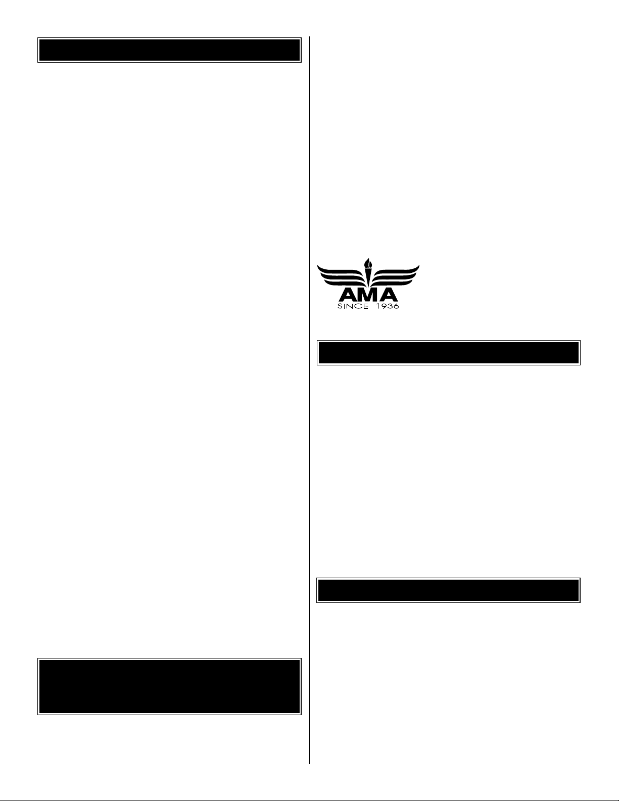
Pushrod Template #1
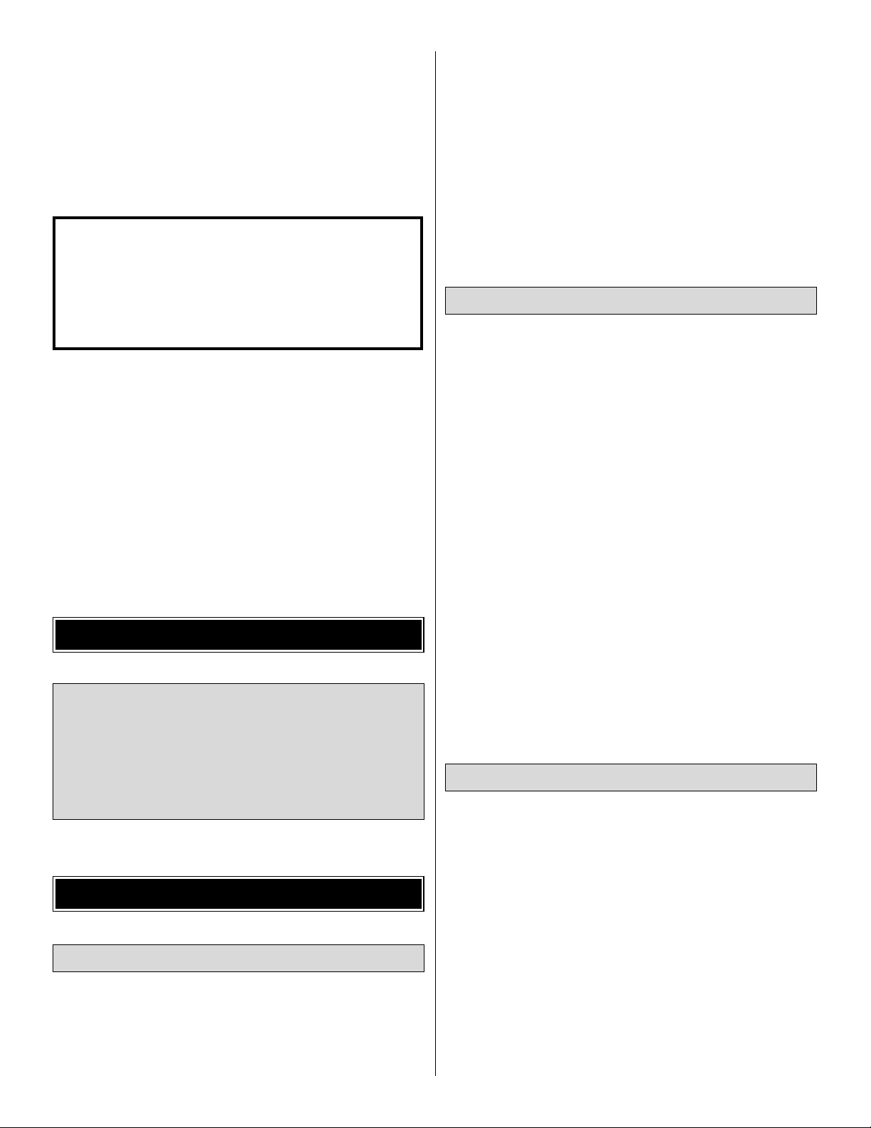
Pushrod Template #2
Refer to these Pushrod Templates when instructed in this manual.
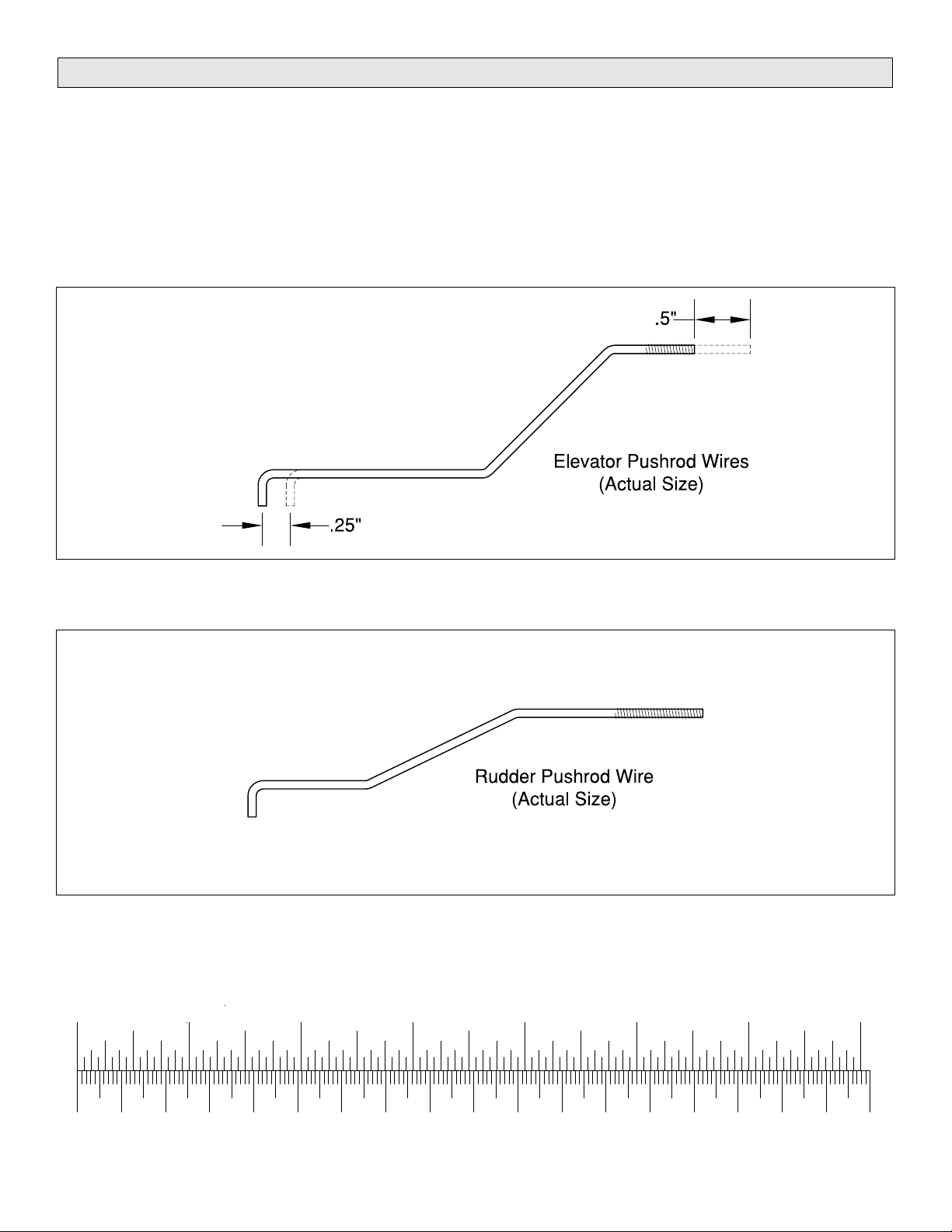
Inch Scale
0" 1" 2" 3" 4" 5" 6" 7"
0 10 20 30 40 50 60 70 80 90 100 110 120 130 140 150 160 170 180
Metric Scale
Page 5
5
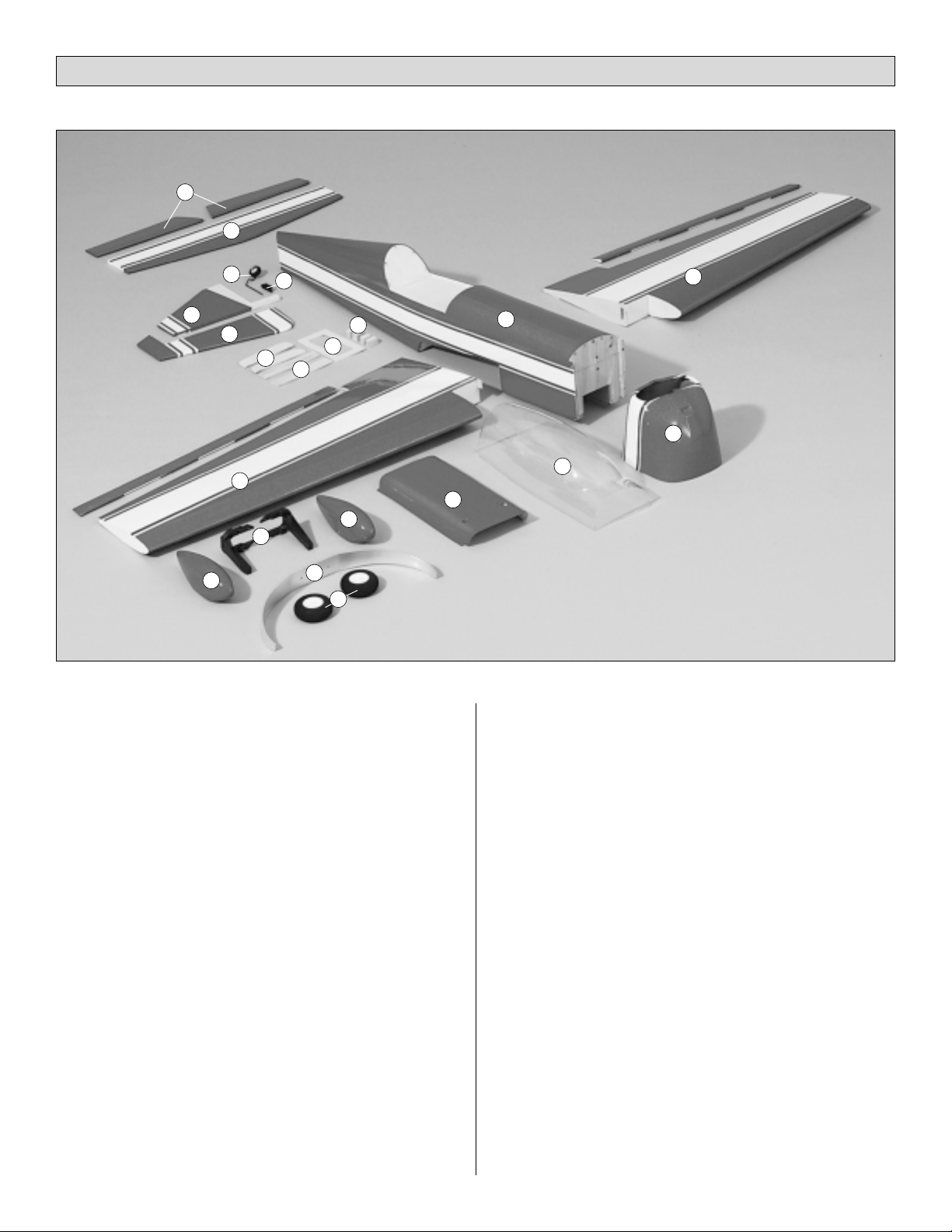
Key# Description Qty
1
Fuselage 1
2 Left Wing Panel w/Aileron 1
3 Right Wing Panel w/Aileron 1
4 Cowl 1
5 Adjustable Engine Mount 2
6 Wing Belly Pan 1
7 Canopy 1
8 Right Wheel Pant Halves 2
9 Left Wheel Pant Halves 2
0 Aluminum Landing Gear 1
-Main Wheels 2
=
Stabilizer 1
q Elevator Assembly 2
w Rudder 1
e Vertical Fin 1
rTail Wheel Assembly 1
t Tail Wheel Bracket 1
yCowl Mounting Blocks 4
u Servo Tray 1
i Belly Pan Formers 1
o Wing Joiners 1
Parts Not Shown In Photo
Description Qty
Propeller Spinner (Red) 1
1" Fiberglass Tape 1
CA Hinge Strip (2" x 9") 1
Hardware Bag 1
Decal Sheet 1
Replacement Parts
If needed, replacement parts for Extra 300 ARF are
available
through your hobby supplier.
Wing Set............................................................GPMA2170
Fuselage Kit ......................................................GPMA2171
Tail Fin Set.........................................................GPMA2172
Canopy..............................................................GPMA2173
Cowl ..................................................................GPMA2174
Wheel Pants......................................................GPMA2175
Landing Gear Set..............................................GPMA2156
Parts List
61093185141519
12
2
20
178
21
41617
11
13
Page 6
❏ 1. Coat the firewall and all other bare wood around the
firewall with fuelproof paint or 30-minute epoxy thinned with
alcohol. Fuelproof other areas of bare wood in the fuselage
that may be exposed to fuel or engine exhaust such as the
fuel tank area and the front and back of the wing saddle.
Avoid getting epoxy in the threads of the blind nuts in the
back of the firewall.
❏ 2. Set the fuselage aside while the paint dries and you
work on the wing.
❏❏1. Cut the covering 1/8" inside the edges of the
opening in the bottom of the right wing panel for the aileron
servo. Use your Top Flite MonoKote Trim Iron to seal the
covering to the sides of the opening.
Note: Inside the wing you’ll notice a piece of string with a
piece of wood tied to it. Don’t remove the string because
you will use it to pull your aileron servo cord through the
wing later.
❏❏2. Cut the covering from the half-inch hole in the top
of the wing sheeting near the root (for your servo cords to
exit) and from the hole near the TE for the wing bolt.
❏3. Repeat this procedure for the left wing panel.
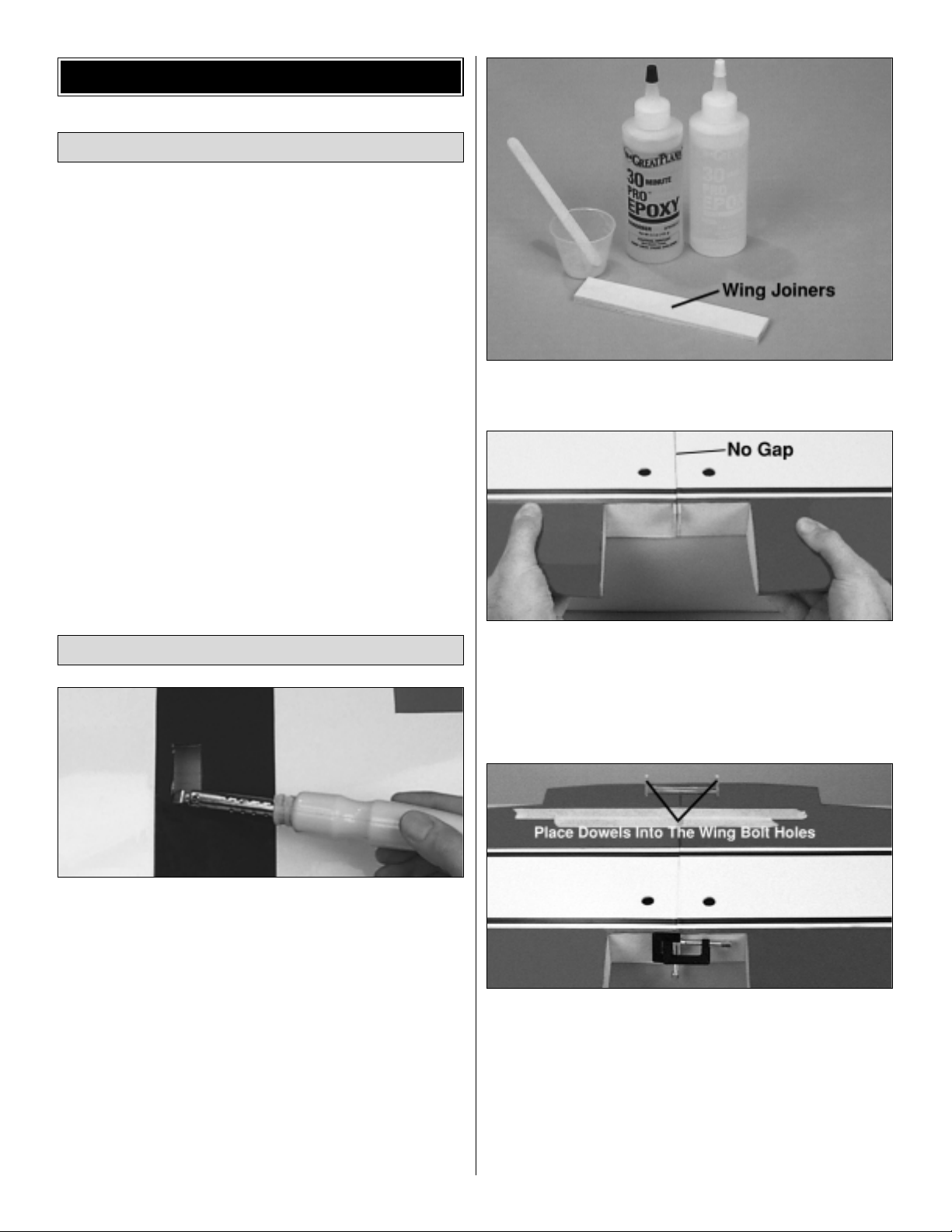
❏4. Use 30-minute epoxy to glue both 1/8" x 15/16" x 5-
1/4"
plywood wing joiners together. Wipe away any excess
epoxy .
❏ 5. Test fit the wing halves with the wing joiner. If
necessary, sand any high spots on the root end of the wing
panels so there is no gap when you join them.
Make a dry run of the following step without using any
glue so you will know how to clamp your wing together.
❏ 6. Thoroughly coat the joiner pockets and the mating
ends of both wing halves with 30-minute epoxy. Set the
wing halves aside and proceed quickly. Coat all surfaces of
one half of the wing joiner with 30-minute epoxy and place
it in one of the wing halves. Coat the other half of the joiner
with 30-minute epoxy and join the other wing. Use a piece
of balsa or cardboard to wipe away excess epoxy. Use two
C-clamps to hold the front of the wing together and use
masking tape to tightly tape the rest of the wing together.
Join the Wing Halves
Fuelproof the Fuselage
BEGIN CONSTRUCTION
6
Page 7
Insert short dowels or a couple of screwdrivers into the
wing bolt holes and wrap the dowels with rubber bands for
additional clamping power at the rear of the wing. Be
certain the trailing edges align. Use a tissue dampened with
alcohol to wipe away any more epoxy that oozes out of the
wing, then set the wing on one of its tips leaning against
a
wall. Do not disturb the wing until the epoxy has fully
cured.
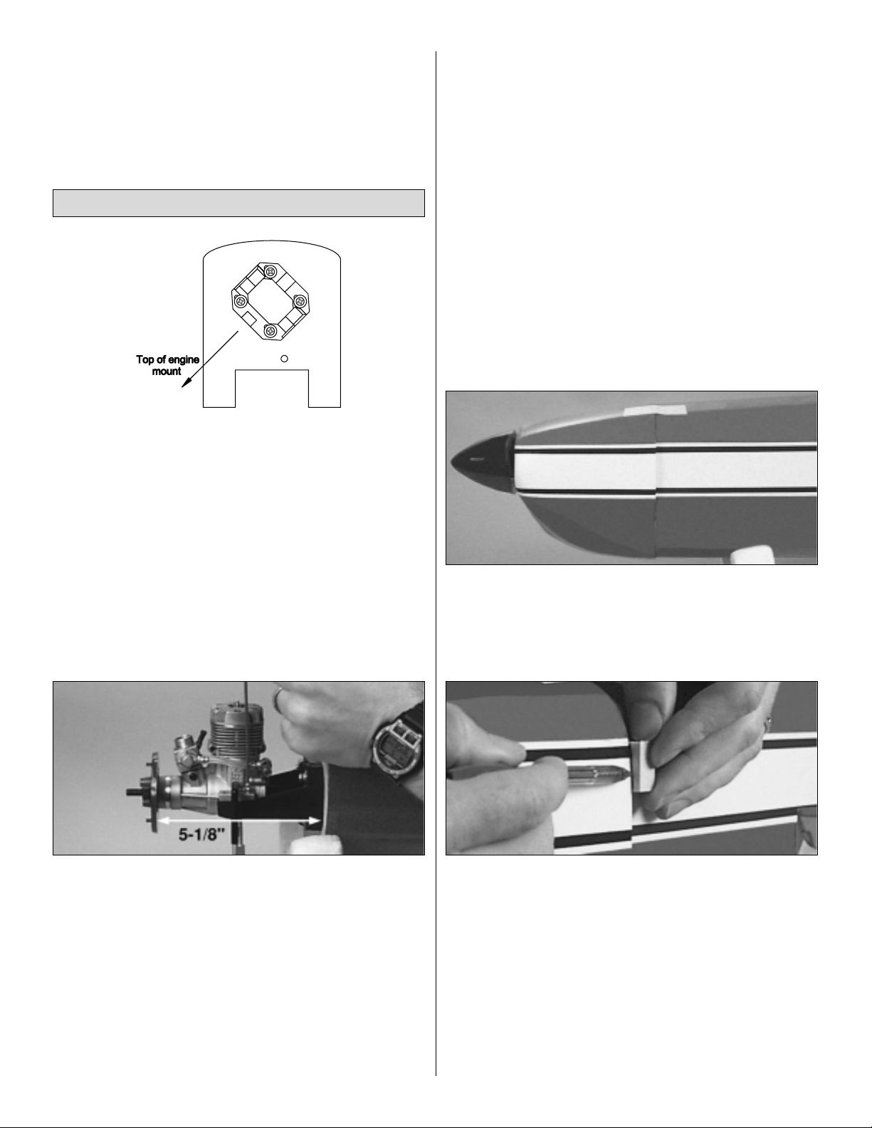
❏ 1. Cut the spreader bar from both engine mount halves
and trim any remaining plastic so the halves slide together.
Temporarily mount your engine mount to the firewall as
shown in the sketch with four 6-32 x 1" SHCS (socket head
cap screws), #6 lock washers and #6 flat washers but don’t
tighten the screws all the way yet.
❏ 2. Adjust the engine mount so it will fit your engine.
Tighten the engine mount screws. Temporarily place the
back plate of the spinner included with this kit on your
engine. Refer to the following photo. Position your engine
on the mount so the spinner back plate is 5-1/8" from the
firewall. Hold your engine to the mount with small clamps or
something similar.
❏3. Mark the location of the engine mounting holes on the
engine mount. We use the Great Planes Dead Center
Engine
Mount Hole Locator (GPMR8130) shown in the photo.
❏ 4. Remove your engine from the mount and drill 7/64"
holes at the marks you made. Add a drop of household oil
to the holes in the mount (so it will be easier for you to
install the screws), then mount your engine to the mount
with four #6 x 1" screws and #6 flat washers. Hint: If you
have a drill press (or if you can borrow your friend’s),
remove the engine mount from the firewall and drill the
holes using the drill press.
Note: Some modelers prefer to mount their engines with
machine screws (not included) rather then the sheet metal
screws supplied with this kit. The Great Planes Adjustable
Engine Mounts accept threads well, so if this is your choice
use the appropriate drill and tap for the screws you intend
to use. 4-40 Screws are acceptable but use 6-32 screws if
they will fit into your engine. Tap the threads into the holes
and mount your engine.
❏ 5. Remove the spinner back plate from your engine,
then slip the cowl over the front of the fuse. If the head of
your engine interferes with the cowl, you can temporarily
remove the head, or cut a hole in the cowl just large
enough to accommodate the engine. After the cowl is
mounted, you can enlarge the hole to allow some
clearance for a more finished appearance.
❏ 6. Reinstall the spinner. Align the front of the cowl with
the spinner and tape it to the fuselage. Use the stripes on
the cowl and the fuselage as a cue for alignment.
❏ 7. Position one of the 1/2" x 1/2" x 3/4" hardwood cowl
mounting blocks at the aft edge of the left side of the cowl
near the top. Use a ballpoint pen to mark the aft edge of the
cowl on the cowl mounting block. Mark the remaining three
cowl mounting blocks the same way for the left side of the
cowl near the bottom and the right side of the cowl near the
bottom and the top.
❏ 8. Trim the cowl mounting blocks along the lines you
marked in step 7.
Mount the Engine & Install the Fuel Tank
7
Page 8
❏ 9. Cut the covering from the front edge of the fuse for
the cowl mounting blocks and glue them in position.
❏ 10. Reposition the cowl on the fuse and mount the
spinner to your engine. Align the cowl with the spinner and
the fuse and tape it in position. View the cowl carefully to
make sure the cowl is centered horizontally and vertically
on the spinner.
❏ 11. Drill a 5/64" (or 3/32") hole through the cowl and one
of the cowl mounting blocks. Screw a #4 x 1/2" SMS (sheet
metal screw) through the cowl just far enough into the cowl
mounting block to temporarily hold that part of the cowl in
place. One at a time, drill a hole and insert a screw into the
remaining three cowl mounting blocks the same way.
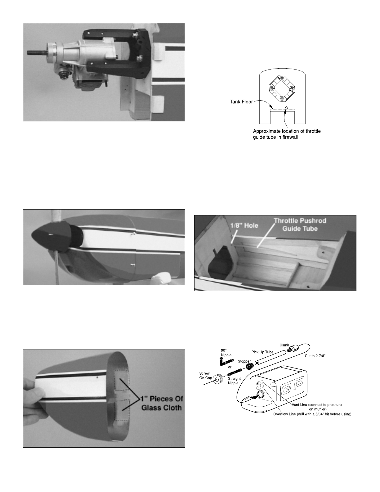
❏ 12. Remove the spinner and cowl. Roughen the inside
of the cowl around the four screw holes with 80-grit
sandpaper. Cut four 1" pieces from the strip of glass cloth
and glue them to the inside of the cowl over the mounting
holes with 30-minute epoxy as shown in the photo. Set the
cowl aside while the epoxy cures. Use a small amount of
epoxy to fuelproof the cowl mounting blocks.
❏ 13. Mark the firewall where the throttle pushrod guide
tube will enter. This location may vary depending on your
engine. Make sure the guide tube will not interfere with the
fuel tank. Ideally, the hole should be 3/16" above the
bottom edge of the firewall so it can rest on top of the fuel
tank floor behind the firewall. Drill a 1/8" hole through the
firewall for the throttle pushrod guide tube.
❏ 14. Drill a 1/8" hole through the former where shown in
the photo. Roughen the outside of the guide tube so glue
will stick, then insert the throttle pushrod guide tube
through the firewall and the former. You will cut the guide
tube to the correct length when you install the servos.
❏ 15. Cut the clear pick up tube included with this kit to a
length of 2-7/8". Assemble the fuel tank as shown in the
sketch using the straight nipple. After you assemble the
tank hold it up to the light and make sure the clunk does
not contact the rear of the tank. If necessary, disassemble
the tank and shorten the pick up tube.
8
10oz. (300cc)
Page 9

❏ 16. Wrap the tank with 1/4" foam rubber secured with a
couple of rubber bands. Tie a piece of string to the loop in
the back of the tank so you can pull it out of the fuselage
when you do your seasonal fuel tank inspection (you do
perform a fuel tank inspection at the beginning of each
flying season, don’t you?)
❏17. Remove your engine mount. Drill 15/64" (or 1/4")
holes
through the firewall for your fuel lines. Make sure you drill
the holes where they will not interfere with the engine mount.
❏18. Fit approximately 12" to 14" of fuel line on the pickup
and vent lines of your fuel tank. Pull the fuel lines through
the holes you drilled in the firewall as you install your tank.
Be certain you do not kink the fuel lines.
❏ 19. Secure your fuel tank by stuffing extra foam rubber
in the fuselage behind the tank.
Before we move on, we might as well finish up the rest of
the “front end.”
❏ 20. Mount your fueling system. We used a Great Planes
Easy Fueler™Fuel Filling Valve (GPMQ4160, not included
with this kit). Mount the filler valve on the carb inlet side of
the engine compartment on a scrap piece of 1/8" plywood
(not included).
❏ 21. Enlarge the four 1/16" mounting holes you drilled in
the cowl with a 1/8" drill. Fit the cowl on the fuse over the
cowl mounting blocks. If necessary, trim the cowl mounting
blocks to accommodate the added thickness of the glass
cloth so you don’t have to force the cowl into place.
❏ 22. Mount your muffler to your engine. Trim the cowl
where necessary so it does not interfere with the muffler
allowing an approximate 1/8" clearance all the way around.
Trim the cowl to accommodate your fuel filler and needle
valve as well.
❏ 1. Use a fresh #11 blade to trim the covering from the
slots in the aft end of the fuse for the stab and fin.
❏ 2. Measure the top of the stab and accurately mark the
center with a felt-tip pen. Use a 90° triangle to mark a
vertical centerline across the mark you made.
Mount the Stab & Fin
9
Page 10

❏ 3. (Refer to this sketch while you align the stab.) Slide
the stab into the fuse. Align the centerline you marked with
the slot for the fin. Measure the stab on both sides of the
fuse to make sure it is centered (A=A).
❏ 4. Remove your cowl if it’s on the fuselage. Insert a
T-pin into the top, middle stringer over the firewall in the
front of the fuselage. Tie a small loop at one end of a 40"
piece of monofilament string and slip it over the T-pin.
❏ 5. Fold a piece of masking tape over the other end of
the string and draw an arrow on it. Slide the tape along the
string and align the arrow with one end of the stab. Swing
the string over to the other end of the stab. Shift the stab
and slide the tape along the string until the distances
between both ends of the stab and the front of the fuse are
equal (B=B). Now your stab is centered and square with
the fuse.
❏ 6. Use a felt-tip pen to mark the sides of the fuselage on
the top and the bottom of the stab. Remove the stab from
the fuselage.
❏ 7. Use a fresh #11 blade to carefully cut through the
covering 1/16" inside the lines you marked on the top and
bottom of the stab that indicate the fuse sides. Do not cut
the wood under the covering! This will weaken the
structure and may cause the stab to fail in flight.
Remove the covering from the center of the stab within the
lines you cut.
❏8. Reinstall the stab in the fuse. Bolt the wing to the fuse
with two 6-32 x 1-1/2" bolts and flat washers. View the
fuselage from the rear and make sure the stab is parallel to
the wing as shown in the sketch (A=A). If the stab is not
parallel to the wing, remove the stab and carefully sand
the fuse where it interferes with the stab, allowing the stab
to become parallel to the wing. Reinstall the stab and
recheck alignment from behind the fuse. Sand the fuse as
necessary until the stab is parallel with the wing. Proceed
carefully and remove only a small amount of material at
a time.
10
Page 11

❏ 9. Now it’s time to glue the stab to the fuse. Position the
stab in the fuse so the exposed balsa of the center section
is visible. Apply a film of 30-minute epoxy to the bare balsa
on both sides of the stab and slide it into position making
sure you distribute enough epoxy in the opening. Repeat
this procedure once more to make sure you have
distributed plenty of epoxy in the stab saddle. Recheck
alignment using the pin-and-string technique shown earlier.
Wipe away excess epoxy before it cures and use T-pins to
hold the stab in position until the epoxy has fully cured.
❏ 10. Test fit the fin into the fuselage. Trim where
necessary so the TE of the fin aligns with the end of the
fuse.
❏ 11. Use 30-minute epoxy to glue the fin to the fuse. If
necessary, use masking tape to hold the fin perpendicular
to the stab. Apply a thin coat of epoxy to the bare wood on
the TE of the fin. Do not disturb the fuselage until the epoxy
has fully cured.
❏ 1. Slip the tail gear wire into the plastic tail gear
bracket. Make certain you have installed the gear into the
bracket correctly, then make a 90° bend in the wire 1" from
the end.
❏ 2. Using the tail gear bracket as a template holding it in
the location shown, drill four 1/16" holes on the bottom of
the fuse. Mount the tail gear to the bottom of the fuse with
four #2 x 3/8" screws.
❏ 3. Hold the rudder to the fin next to the tail gear wire (or
tape the rudder to the fin). Mark the rudder where the arm
portion of the tail gear wire will enter.
❏ 4. Cut a groove in the LE of the rudder and drill a 3/32"
hole where you made your mark to accommodate the tail
gear wire. Hint: Use a 3/32" brass tube sharpened at the
end to cut the groove.
Mount the Landing Gear
11
Page 12

❏ 5. Test fit the rudder to the tail gear wire. View the
rudder and the tail gear wire from above (when the
fuselage is upside down in your cradle). If necessary, bend
the tail gear wire so your model will taxi straight when your
rudder is centered.
❏ 6. Mount a 1" tail wheel to the tail gear wire with a 3/32"
wheel collar and set screw on both sides of the wheel.
Secure the set screws with a drop of Great Planes Pro
Threadlocker (GPMR6060) or similar thread locking
compound.
❏ 7. Use the sketch above to make two wheel pant
mounts from the 1/8" x 1" x 2" plywood sheet.
❏ 8. Use 80-grit sandpaper to scuff the inside of both
wheel pants where the wheel pant mounts are to be
located. Glue the wheel pant mounts inside the wheel pants
with medium CA.
❏ 9. Use a metal file to round the edges of the landing
gear where it keys into both wheel pants. Fit one of the
wheel pants to the landing gear, then mark the hole in the
gear onto the wheel pant. Mark the other wheel pant using
the same procedure.
❏ 10. Drill a 3/16" (or 11/64" or #18) hole in both wheel
pants at the mark you made.
❏ 11. (Refer to this sketch for mounting the wheel and
wheel pant on the landing gear.) Fit a 2-1/2" wheel on a
8-32 x 1-1/2" axle. If the wheel does not fit on the axle or
spin freely, enlarge the hole in the wheel with a 11/64" or
#18 drill. Screw a 8-32 nut onto the axle about 1/8".
❏12. Slip the wheel with the axle and nut partway into one
of the wheel pants.
❏ 13. Use a 9/64" hex wrench to screw the axle into the
plywood wheel pant mount until it comes out of the
opposite
side of wheel pant.
❏ 14. Use needle nose pliers or hemostats to tighten the
nut inside the wheel pant until free play on the axle is
removed, but the wheel can still roll freely.
❏ 15. Fit the other wheel into the other wheel pant using
the same procedures as above.
❏ 16. If you wish to polish or paint the pre-bent aluminum
landing gear, now is the time to do it.
12
Page 13

❏ 17. Mount both wheel pants to the landing gear with a
drop of Great Planes Threadlocker or similar thread locking
compound and a 8-32 hex nut on both axles.
❏ 18. If necessary, trim the opening in the wheel pants so
the wheels can roll freely. Add a drop of household oil to the
axles on both sides of the wheels.
❏ 19. Mount the main landing gear to the fuselage with
two 8-32 x 3/4" SHCS.
❏ 1. Cut fifteen 3/4" x 1" hinges from the CA hinge strip
supplied with this kit. Snip the corners off so they go into
the slots easier. You may cut all the hinges now, or cut
them as you need them.
Before you glue in the hinges, apply a few drops of
household oil to a tissue. Wipe the tissue over the trailing
edge of the fin and the leading edge of the rudder coating
them with a fine film of oil. This will prevent excess CA
you use for gluing in the hinges from sticking to the
rudder and fin at the hinge gap.
❏ 2. Test fit the rudder to the fin and the tail gear wire with
the hinges. If the hinges are difficult to install or don’t go in
far enough, carefully enlarge the hinge slots with a hobby
knife and a #11 blade.
❏ 3. Drill a 3/32" hole, 1/2" deep, in the center of the hinge
slot. If you use a Dremel®MultiPro™for this task, it will
result in a cleaner hole than if you use a slower speed drill.
Drilling the hole will twist some of the wood fibers into the
slot, making it difficult to insert the hinge, so you should
reinsert the knife blade, working it back and forth a few
times to clean out the slot.
❏ 4. If the hinges don’t remain centered, remove the
rudder and insert a pin in the center of the hinges.
❏ 5. Pack the tail gear wire hole and the groove in the LE
of the rudder with epoxy. If you work quickly, you may use
5-minute epoxy, but we recommend 30-minute epoxy.
Rejoin the rudder to the fin using the hinges. Use a tissue
dampened with alcohol to wipe away excess epoxy before
it cures. Make sure there is approximately a 1/64" gap
between the rudder and the fin.
TEMPORARY PIN
TO KEEP HINGE
CENTERED
DRILL A 3/32" HOLE
1/2" DEEP, IN CENTER
OF HINGE SLOT
Rudder Assembly
JOIN THE CONTROL SURFACES
13
1"
1"
3/4"
Page 14

❏ 6. Cut a paper towel into approximately 2" squares.
Place the fuselage on it’s side so the fin and rudder are
horizontal. Add six drops of thin CA to the center of the
hinges on both sides. Use the paper towel squares to
absorb excess CA from the hinge gap before it cures. Do
not use CA accelerator; allow the CA to cure slowly.
❏ 7. Use the same hinging method to join the elevators to
the stab and the ailerons to the wing.
❏8. After all your control surfaces are securely hinged and
the CA has thoroughly hardened, move the control surfaces
back and forth to loosen them up a little so it will be easier
for your servos to move them.
❏ 1. If you haven’t already done so, install the rubber
grommets and eyelets in your aileron servos. Pull the string
out of one of the aileron servo compartments in the wing.
Tie the string to the servo cord on one of the aileron servos.
❏ 2. Fit the aileron servo in the wing. Hold the servo to the
wing so the sides don’t contact the wing and drill 1/16"
holes for the servo mounting screws. Mount the servo to
the wing with the screws included with your servos.
❏3. Mount your other aileron servo to the other side of the
wing using the same procedures as above.
❏❏4. Cut the unused arms from one of your servo horns
and mount it on one of your aileron servos in the wing.
❏❏5. Refer to the following photo. Use alcohol or other
solvent to clean the film of oil from the five .074" x 12" wire
pushrods. Screw a nylon clevis about fourteen turns onto
one of the pushrods. Connect the clevis to the second from
the outer hole of a nylon control horn.
❏❏6. Hold the control horn on the aileron making sure
the holes align with the hinge gap. Use the control horn as
a template to drill 3/32" holes through the aileron for the
mounting screws.
Hookup the Ailerons
ASSEMBLE, THEN APPLY 6 DROPS
14
OF THIN CA TO CENTER
OF HINGE, ON BOTH SIDES
THE CA WICKS
ALONG THE "TUNNELS"
TO THE ENTIRE
HINGE SURFACE
CUT OFF
UNUSED
ARMS
Page 15

❏❏7. Mount the control horn to the aileron with two 2-56
x 5/8" screws and the nylon backing plate that was
attached to the control horn. Slide a silicone retainer onto
each clevis.
❏❏8. Use a felt-tip pen to mark the pushrod wire where
it crosses the holes in the aileron servo arm.
❏❏9. Bend the pushrod at the mark you made. Cut the
excess wire as shown in the sketch and connect the
pushrod to the servo arm with a nylon Faslink.
❏ 10. Return to step 4 and connect the other aileron servo
to the other aileron the same way.
❏11. Turn the wing over. Use a piece of bent wire to fish
the
string out of the 1/2" holes in the center section of the wing
and retrieve your aileron servo cords. Connect both aileron
servo cords to a “Y” harness.
❏ 1. Cut one of the pushrod dowels to a length of 19".
Drill two 5/64" (or 3/32") holes in one end of the pushrod as
shown in the sketch. This is the aft end of the pushrod
dowel.
❏2. Drill another 5/64" hole 1" from the other end (front) of
the pushrod dowel.
❏ 3. (See the Pushrod Template #1, on page 4 for this
step.) Cut 1/2" from the threaded end of two .074" x 12"
wire pushrods. Make the elevator pushrod wires as
shown in the sketch from the two rods. Note that the sketch
shows two rods, one 1/4" shorter than the other. Save the
leftover pushrod wire to be used at the front of the
pushrods. You should have two scrap pieces of wire,
approximately 6" long.
❏ 4. Use a hobby knife to cut grooves in the aft end of the
pushrod dowel to accommodate the elevator pushrod
wires. Test fit the pushrod wires and adjust the grooves as
necessary for a good fit. Hint: Once you get the groove
started, use the threaded end of another pushrod as a file
to make the groove just the right size.
❏ 5. Cut a groove in the front end of the pushrod dowel
using the same procedure as in step 4.
Install the Elevator Pushrod
15
FasLink
Servo Horn
2-56 (.074") Pushrod Wire
Page 16

❏ 6. Cut a piece of 3" black heat shrink tubing into two
1-1/2" pieces. Secure the elevator pushrod wires to the
pushrod dowel with a 1-1/2" piece of heat shrink. Use a
match or lighter flame or a heat gun to shrink the tubing.
After the tubing cools, permanently bond the tubing and the
wires to the pushrod dowel with thin CA.
❏ 7. Cut the covering from the pushrod exit slots nearest
the stab on both sides of the fuse. Install two outer guide
tubes (from a Great Planes Flexible Cable Pushrod kit,
GPMQ3702, not included) through the slots. Route the
guide tubes through the fuse into the radio compartment.
Screw the guide tubes to the threaded ends of the elevator
pushrod wires.
❏8. Pull the guide tubes out of the fuselage until the pushrod
wires come out of the slots. Remove the guide tubes.
❏ 9. Thread a nylon clevis onto the right pushrod wire
about twenty turns. Connect the clevis to the outer hole of a
nylon control horn. Connect another clevis and control horn
to the left pushrod wire the same way.
❏ 10. Adjust the clevises (and the bends in the pushrod
wires if necessary) so both control horns rest on the
elevator in the exact same location. Make sure the holes in
the control horn align with the hinge gap. Using the horns
as a template, drill 3/32" holes through the elevators and
mount the control horns with 2-56 x 5/8" screws and the
nylon plates. Slide the silicone retainers onto each clevis.
❏ 1. Cut the other pushrod dowel to a length of 19-1/2" for
the rudder pushrod dowel. The same as you did for the
elevator pushrod dowel, drill a 1/16" hole 1" from both ends
of the dowel and make grooves for the pushrod wires.
❏ 2. (See the Pushrod Template #2, on page 4 for this
step.) Make a rudder pushrod wire as shown in the sketch
from a .074" x 12" wire pushrod. Secure the pushrod wire
to the pushrod dowel with the other piece of 1-1/2" heat
shrink tube and thin CA.
❏ 3. Install the rudder pushrod in the fuse using an outer
pushrod guide tube to pull it through the same way you did
with the elevator pushrods. Connect the pushrod to the
rudder with a nylon clevis, a control horn, two 2-56 x 5/8"
screws and the nylon backing plate. Slide the silicone
retainers onto each clevis.
❏ 1. Place the fuselage upside down in your building
stand. Bolt the wing to the fuselage.
Install the Wing Belly Pan
FINAL ASSEMBLY
Install the Rudder Pushrod
16
Page 17

❏ 2. Trim the 1/8" plywood forward and aft belly pan
formers so they match the fuse when placed in position.
❏ 3. Remove the covering only where the plywood belly
pan formers contact the bottom of the wing. Use thick or
medium CA to glue the belly pan formers to the wing. Make
sure you don’t inadvertently glue the wing or the belly pan
formers to the fuse.
❏ 4. Use 320-grit sandpaper to lightly scuff the covering
where the molded ABS belly pan will contact the bottom of
the wing. Similarly, scuff the bottom of the belly pan where
it will contact the wing.
❏ 5. Position the belly pan on the wing and use thin CA to
glue it in place.
❏ 6. Unbolt the wing from the fuselage and glue the belly
pan formers to the belly pan with medium CA. Now would
be a good time to fuelproof the bare wood on the front of
the wing and the belly pan formers the same way you
fuelproofed the firewall and other parts of the fuse.
❏ 1. Add whatever scale details you would like to the
cockpit, then glue in your pilot, or just paint the cockpit black.
❏ 2. Trim the clear molded canopy along the molded-in
cutlines. Use a sanding block and 220-grit sandpaper to
true the edges of the canopy for a finished appearance.
❏ 3. Wash the dust and fingerprints from the canopy with
lukewarm soapy water. If you wish to paint a frame on the
canopy to resemble the full size Extra, now is the time to do
so. Use a paint that is compatible with the canopy. Always
test your paint on a piece of leftover plastic cut from the
canopy. We suggest Pactra Formula-U or Chevron.
❏ 4. Mount the canopy to the fuselage. The easiest way is
to tape the edges of the canopy to the fuse with 1/4" red
striping tape, or use canopy glue for the most permanent
installation.
❏ 1. If you haven’t already done so, mount the grommets
and eyelets to your elevator, throttle and rudder servos.
❏ 2. Test fit your throttle, elevator and rudder servos in the
1/8" plywood servo tray. If necessary, enlarge the opening
in the servo tray so the sides of your servos will not contact
the servo tray. Position the servo tray in the fuselage but do
not glue it in place until instructed to do so.
❏ 3. Mount the cowl, prop and spinner and temporarily
place your battery pack and receiver inside the fuselage at
the location where you intend to mount them.
❏ 4. Bolt the wing to the fuselage. Refer to the balance
point in the sketch on page 19. Use thin strips of tape or a
felt-tip pen to accurately mark the balance point on the top
of the wing where it meets both sides of the fuselage.
❏ 5. Turn the model upside down and lift the wing at the
balance point or place it on a Great Planes C.G. Machine
(GPMR2400). If the nose tilts downward, your model is
nose heavy. Remove the wing and move the servo tray aft
or shift the receiver and battery pack aft. If the tail tilts
downward, your model is tail heavy. Remove the wing and
move the servo tray forward or sift the receiver and battery
pack forward. Reposition the model on your C.G. Machine
or lift it at the balance point again.
Mount the Servo Tray
Mount the Canopy
17
Page 18

❏6. Shift the radio components until you can get the model
to balance as closely as possible to the indicated balance
point. This isn’t the final C.G. check, but it will enable you
to minimize (or altogether eliminate) the amount of lead
required to finally balance your model. Our model using an
O.S. .46 SX balanced with the servo tray as far aft as
possible, a 500mAh battery pack just in front of the servo
tray and the receiver just behind the servo tray. Your model
may vary.
❏ 7. Glue the servo tray in position. Temporarily remove
the battery pack and receiver noting their location to
achieve the correct C.G.
❏ 8. Use one of the scrap pieces of pushrod wire
(approximately 6" in length), to make the front wire pushrod
for the elevator. Make a 90° “L” bend in the end of the wire
and secure it to the front of the elevator pushrod dowel with
a 1-1/2" long piece of heat shrink tubing and thin CA.
❏ 9. Place a one-arm servo horn on the elevator (middle)
servo on the servo tray. Position the elevator servo in the
servo tray so the elevator pushrod will run straight down
the middle of the fuselage when connected to the servo.
Drill 1/16" holes and mount the elevator servo to the servo
tray.
❏ 10. Mark, bend, then cut the excess off the pushrod the
same way you did for the ailerons, and connect it to your
elevator servo with a nylon Faslink.
❏ 11. Connect the rudder pushrod to the rudder servo the
same as the elevator using heat shrink tubing to secure the
pushrod wire to the dowel and using a Faslink to connect
the wire to the servo. Drill 1/16" holes and mount the rudder
servo to the servo tray. You can see the rudder servo in
following photos.
❏ 12. Place a servo horn on your throttle servo. Cut the
throttle guide tube approximately 1-1/2" in front of the
throttle servo horn.
❏ 13. Remove the cowl and guide the thin throttle
pushrod
wire through the throttle guide tube. Make a
“Z-bend” on the
end of the pushrod wire and connect it to the throttle servo.
❏ 14. Cut the throttle pushrod wire to the correct length,
then connect it to the carb arm using a screw-lock
pushrod connector and a 4-40 x 1/4" SHCS. Secure the
screw-lock pushrod connector to the carb arm with a nylon
retainer.
❏ 1. (Refer to this photo for mounting your radio.) Connect
your servo cords, switch and an aileron extension cord to
Final Radio Installation
18
RETAINER
Page 19

your receiver. Wrap the receiver in foam rubber and mount
it in the location determined earlier. Glue a piece of 1/8"
balsa or plywood to securely hold your receiver in position.
Be certain that nothing interferes with the pushrods or
servo horns.
❏ 2. Wrap your battery pack and mount it in the
predetermined location the same as the receiver. Be certain
the battery pack is secure so it will not become dislodged
during aerobatic maneuvers.
❏ 3. Mount the on/off switch and charging jack in a
strategic location that will not interfere with other radio
components but is easy to reach from outside the model.
❏4. Make a strain relief from a cutoff servo arm and fit it to
your antenna. Route the antenna out the bottom (or side) of
the model and attach it to a T-pin or the tail gear wire with a
small rubber band. Do not push the T-pin through the
antenna wire.
Note: This section is IMPORTANT and must NOT be
omitted! A model that is not properly balanced will be
unstable and possibly unflyable.
All components should be in the model and it should be
ready-to-fly with an empty fuel tank. Lift your model at the
balance point or place it on your Great Planes C.G.
Machine. Your balance point should be pretty close since
we’ve already pre-balanced it. If necessary, add nose
weight or tail weight to balance the model where indicated.
Note: Nose weight may be easily installed by using a
spinner weight or gluing lead weights to the firewall. Tail
weight may be added by using Great Planes (GPMQ4485)
“stick-on” lead weights. Later if the balance is O.K., you can
open the fuse bottom and glue the weights in permanently.
Do not confuse this procedure with checking the C.G. which
you already performed.
❏ 1. With the wing level and attached to the model (and
the engine and muffler installed), lift the model by the
propeller shaft and the fin. This may require an assistant.
Do this several times.
❏ 2. The wing that consistently drops indicates the heavy
side. Balance the model by adding weight to the other
wing tip.
An airplane that is laterally balanced will track better during
aerobatic maneuvers.
❏ 1. Take the servo horns off your servos, turn on your
transmitter and center all the trims. Reinstall all the servo
horns and secure them with the screws.
❏ 2. Double-check all the servos and make sure the servo
horns are secure. Install a silicone retainer on all clevises.
Final Hookups & Checks
Balance the Model Laterally
This is the balance point at which your model should be
balanced for your first flights. Later, you may experiment
by shifting the balance up to 1/4" forward or backward
to change the flying characteristics. If you move the
balance point forward it may improve the smoothness
and tracking, but your Extra 300 ARF may then require
more speed for takeoff and become more difficult to slow
for landing. If you move the balance aft it may make your
Extra 300 ARF more agile with a lighter feel and allow you
to slow the model more for landing. In any case, please
start at the location we recommend and do not at any
time balance your model outside the recommended
C.G. range.
Balance Your Model
GET YOUR MODEL READY TO FLY
19
C.G. Machine
4" [101.6mm]
at fuse
SILICONE RETAINER
NYLON CLEVIS
Page 20

❏ 3. Make sure the control surfaces move in the proper
direction as illustrated in the following sketch.
❏ 4. Adjust your pushrod hookups and set up your radio to
provide the control surface movements as follows. Use a
ruler or a Great Planes Accu Throw Control Surface
Deflection Meter (GPMR2405) to measure the throws.
Note: The balance and control throws for the Extra 300
ARF have been extensively tested. We are confident
that they represent the settings at which the Extra 300
ARF flies best. Please set up your model to the
specifications listed above. If, after you become
comfortable with your Extra 300 ARF, you would like to
adjust the throws to suit your tastes, that’s fine. Too
much throw can force the plane into a snap roll, so
remember, “more is not better.”
No matter if you fly at an AMAsanctioned R/C club site or if
you fly somewhere on your own, you should always have
your name, address, telephone number and AMA number
on or inside your model. It is required at all AMA R/C club
flying sites and AMA sanctioned flying events. Write your
full name, address, telephone number and AMAnumber on
a small card or a piece of paper and securely tape it inside
your model.
Follow the battery charging procedures in your radio
instruction manual. You should always charge your
transmitter and receiver batteries the night before you go
flying, and at other times as recommended by the radio
manufacturer.
Charge Your Batteries
Identify Your Model
PREFLIGHT
We recommend the following control surface throws:
Note: The throws are measured at the widest part of the
elevators and rudder. Adjust the position of the pushrods
at the control horn and/or servo horns to determine the
amount of throw. You may also use the ATV’s if your
transmitter has them, but the mechanical linkages should
still be set so the ATV’s are near 100% for the best servo
resolution (smoothest, most proportional movement).
High Rate Low Rate
ELEVATOR: 5/16" [8mm] up 1/4" [6.5mm] up
3/8" [9.5mm] down 5/16" [8mm] down
RUDDER: 2-1/8" [54mm] right 1-1/2" [38mm] right
2-1/8" [54mm] left 1-1/2" [38mm] left
AILERONS: 3/8" [9.5mm] up 1/4" [6.5mm] up
3/8" [9.5mm] down 1/4" [6.5mm] down
Note: If your radio does not have dual rates, set the
control surfaces to move between the high rate and low
rate throws.
IMPORTANT! Do not exceed the elevator throws
provided. The Extra 300 ARF requires little elevator
throw to perform even the most aggressive
aerobatics. Exceeding the recommended throws may
result in a model that is difficult to control.
Set the Control Throws
20
4-CHANNEL RADIO SET-UP
(STANDARD MODE 2)
ELEVATOR MOVES UP
4-CHANNEL
TRANSMITTER
RIGHT AILERON MOVES UP
LEFT AILERON MOVES DOWN
4-CHANNEL
TRANSMITTER
RUDDER MOVES RIGHT
4-CHANNEL
TRANSMITTER
CARBURETOR WIDE OPEN
4-CHANNEL
TRANSMITTER
Page 21

Carefully balance your propellers before you fly. An
unbalanced prop is the single most significant cause of
vibration that can damage your model. Not only will engine
mounting screws and bolts loosen, possibly with disastrous
effect, but vibration may also damage your radio receiver
and battery. Vibration can also cause your fuel to foam,
which will, in turn, cause your engine to run hot or quit.
We use a Top Flite Precision Magnetic Prop Balancer
™
(TOPQ5700) in the workshop and keep a Great Planes
Fingertip Prop Balancer (GPMQ5000) in our flight box.
The best place to fly your model is an AMA chartered R/C
club flying field. Contact the AMA (their address is on page
2)
or your hobby shop dealer for the club in your area and join
it. Club fields are intended for R/C flying, making your
outing safer and more enjoyable. The AMA also provides
insurance in case of a flying accident. If an R/C flying field
is not available, find a large, grassy area at least six miles
from buildings, streets, and other R/C activities. A
schoolyard is usually not an acceptable area because of
people, power lines and possible radio interference.
If you are not thoroughly familiar with the operation of R/C
models, ask an experienced modeler to inspect your radio
installation and control surface set-up. Follow the engine
manufacturer’s instructions to break-in your engine.
After you run the engine on your model, inspect your model
closely to make sure all screws remain tight and your
pushrods and connectors are secure.
Ground check the range of your radio before the first flight
of the day. With the transmitter antenna collapsed and the
receiver and transmitter on, you should be able to walk at
least 100 feet away from the model and still have control.
Have an assistant stand by your model and, while you work
the controls, tell you what the control surfaces are doing.
Repeat this test with the engine running at various
speeds with an assistant holding the model, using hand
signals to show you what is happening. If the control
surfaces do not respond correctly, do not fly! Find and
correct the problem first. Look for loose servo connections
or broken wires, corroded wires on old servo connectors,
poor solder joints in your battery pack or a defective cell in
your battery pack, or a damaged receiver crystal from a
previous crash.
❏1. Fuelproof all areas exposed to fuel or exhaust residue
such as the firewall/engine compartment, fuel tank
compartment, wing saddle area, etc.
❏ 2. Check the C.G. according to the measurements
provided in the manual.
❏ 3. Secure the battery and receiver with a strip of balsa
or plywood. Simply stuffing them into place with foam
rubber is not sufficient.
❏ 4. Extend your receiver antenna and make sure it has a
strain relief inside the fuselage to keep tension off the
solder joint inside the receiver.
❏ 5. Balance your model laterally as explained in the
instructions.
❏ 6. Secure critical fasteners with thread locking
compound (the screws that hold the carburetor arm, screwlock pushrod connectors, etc.).
❏ 7. Apply a drop of oil to the wheel axles so the wheels
will turn freely.
❏8. Make sure all hinges are securely glued in place.
❏ 9. Reinforce holes with thin CA for wood screws where
servos are mounted.
❏10. Confirm that all controls operate in the correct
direction
and the throws are set up as specified on page 20.
❏ 11. Make sure that there are silicone retainers on all of
the clevises.
During the last few moments of preparation your mind
may be elsewhere, anticipating the excitement of your
first flight. Because of this, you may overlook certain
checks and procedures you should perform after your
model is built. To help you avoid this, we’ve provided a
check list to make sure you don’t overlook these
important areas. Many are covered in the instruction
manual so, where appropriate, refer to the manual for
complete instructions. Be sure to check the items off as
you complete them (that’s why we call it a check list!)
Check List
Range Check Your Radio
Ground Check Your Model
Find a Safe Place to Fly
Balance Your Propellers
21
Page 22

❏ 12. Fasten all servo horns to the servos with the screws
included with your radio.
❏ 13. Secure connections between servo wires and “Y”
connectors or servo extensions, and the connection
between your battery pack and the on/off switch with vinyl
tape or heat shrink tubing.
❏ 14. Make sure any servo extension cords you may have
used do not interfere with other systems (servo horns,
pushrods, etc.)
❏ 15. Make sure your fuel lines and pressure lines are
connected and are not kinked.
❏ 16. Use an incidence meter to check the wing for twists
and correct them before flying.
❏17. Balance your propeller (and spare propellers).
❏18. Tighten the propeller nut.
❏ 19. Place your name, address, AMA number and
telephone number on or inside your model.
❏ 20. Cycle your receiver battery pack (if necessary) and
make sure it is fully charged.
❏ 21. If you wish to photograph your model, do this before
your first flight.
❏22. Range check your radio before flying the model.
Note: Failure to follow these safety precautions may
result in severe injury to yourself and others.
Store model fuel in a safe place away from high heat,
sparks or flames. Do not smoke near the engine or fuel as
it is very flammable. Engine exhaust gives off a great deal
of deadly carbon monoxide so do not run the engine in a
closed room or garage.
Get help from an experienced pilot when learning to
operate engines.
Use safety glasses when you operate model engines.
Do not run the engine near loose gravel or sand; the
propeller may throw loose material in your face or eyes.
When you start and run the engine, keep your face and
body as well as all spectators away from the plane of
rotation of the propeller.
Always be aware and very conscious of hand movements
and be deliberate in your reach for the needle valve, glow
plug clip, or other items near a spinning propeller.
Keep loose clothing, shirt sleeves, ties, scarfs, long hair or
loose objects away from the prop. Be conscious of pencils,
screwdrivers or other objects that may fall out of your shirt
or jacket pockets.
Use a chicken stick or electric starter and follow the
instructions to start your engine.
Make certain the glow plug clip or connector is secure so
that it will not pop off or get into the running propeller.
Ask an assistant to hold the model from the rear while you
start the engine and operate the controls.
Make all engine adjustments from behind the rotating
propeller.
The engine gets hot! Do not touch the engine during or
immediately after you operate it. Make sure fuel lines are in
good condition so fuel will not leak onto a hot engine and
cause a fire.
To stop the engine, close the carburetor barrel (rotor) or
pinch the fuel line to discontinue the fuel flow. Do not use
your hands, fingers or any body part to stop the engine.
Never throw anything into the prop of a running engine.
Read and abide by the following Academy of Model
Aeronautics Official Safety Code:
GENERAL
1. I will not fly my model aircraft in sanctioned events, air
shows, or model flying demonstrations until it has been
proven to be airworthy by having been previously
successfully flight tested.
2. I will not fly my model aircraft higher than
approximately 400 feet within 3 miles of an airport without
notifying the airport operator. I will give right of way to, and
avoid flying in the proximity of full scale aircraft. Where
necessary an observer shall be used to supervise flying to
avoid having models fly in the proximity of full scale aircraft.
3. Where established, I will abide by the safety rules for
the flying site I use, and I will not willfully and deliberately
fly my models in a careless, reckless and/or dangerous
manner.
7. I will not fly my model unless it is identified with my
name and address or AMAnumber, on or in the model.
9. I will not operate models with pyrotechnics (any device
AMA SAFETY CODE (excerpt)
Engine Safety Precautions
22
Page 23

that explodes, burns, or propels a projectile of any kind).
RADIO CONTROL
1. I will have completed a successful radio equipment
ground check before the first flight of a new or recently
repaired model.
2. I will not fly my model aircraft in the presence of
spectators until I become a qualified flier, unless assisted
by an experienced helper.
3. I will perform my initial turn after takeoff away from the
pit or spectator areas, and I will not thereafter fly over pit or
spectator areas, unless beyond my control.
4. I will operate my model using only radio control
frequencies currently allowed by the Federal Communications
Commission (FCC).
The Great Planes Extra 300 ARF is a great flying semiscale sport model that is smooth and predictable, yet is
highly aerobatic. Compared to other sport planes its flight
characteristics are docile and forgiving. The Extra does not,
however, possess the self-recovery characteristics of a
primary R/C trainer; therefore, you must either have
mastered the basics of R/C flying or obtained the
assistance of a competent R/C pilot to assist you with the
first flights of your Extra 300 ARF.
If you have dual rates on your transmitter takeoff on “high”
rates–especially if you are taking off in a crosswind. Gain
as much speed as your runway and flying site will permit
before you lift off. This will give you a safety margin in case
the engine quits. When you initially advance the throttle and
the tail begins to rise, the Extra will begin to turn to the left
(due to the torque of the engine–a characteristic of all tail
draggers). Be prepared for this by applying sufficient right
rudder to keep the Extra running straight down the middle
of the runway. The left turning tendency will decrease as
the plane picks up speed. Be sure to allow the tail to rise off
the ground before lifting the model into the air. Depending
on the surface you are taking off from, you will need to
apply little or no up elevator until flying speed is reached.
Don’t hold the tail on the ground with too much up elevator,
as the Extra will become airborne prematurely and may
stall. When the plane has gained enough flying speed to
safely lift off, gradually and smoothly apply up elevator and
allow the model to climb at a shallow angle. Do not yank
the model off the ground into a steep climb.
We recommend that you take it easy with your Extra 300
ARF for the first several flights, gradually “getting
acquainted” with this great sport model as your engine gets
fully broken-in. If you feel as though you have your hands
full keep this one thing in mind: pull back on the throttle
to slow the model down. This will make everything
happen a little slower allowing yourself time to think and
react. Add and practice one maneuver at a time, learning
how the Extra behaves in each. For smooth flying and
normal maneuvers, use the low rate settings. High rate
elevator may be required for crisp snap rolls and spins. For
good knife-edge performance airspeed is the key.
Before it’s time to land, climb your Extra to a safe altitude
and cut the throttle to an idle. Observe how your Extra
handles at slow speeds so you will know what to expect
when its time to bring ’er in.
When it’s time to land, fly a normal landing pattern and
approach. Keep a few clicks of power on until you are over
the runway threshold. For your first few landings, plan to
land slightly faster than stall speed and on the main wheels,
as this is the easiest way to land your Extra. Later, with a
little practice you will find you can make slow 3-point
landings.
Have a ball! But always remember to think about your
next move and plan each maneuver before you do it.
Impulsively “jamming the sticks” without any thought
rather than lack of flying skill is what gets most fliers
in trouble.
Landing
Flying
Takeoff
CAUTION (THIS APPLIES TO ALL R/C AIRPLANES): If,
while flying, you notice any unusual sounds, such as a
low-pitched “buzz”, this may indicate control surface
“flutter.” Because flutter can quickly destroy components
of your airplane, any time you detect flutter you must
immediately cut the throttle and land the airplane! Check
all servo grommets for deterioration (this may indicate
which surface fluttered), and make sure all pushrod
linkages are slop-free. If it fluttered once, it will probably
flutter again under similar circumstances unless you can
eliminate the slop or flexing in the linkages. Here are
some things which can result in flutter: Excessive hinge
gap; Not mounting control horns solidly; Sloppy fit of
clevis pin in horn; Sloppy fit of Z-bend in servo arm;
Excessive “play” or “backlash” in servo gears; and
Insecure servo mounting.
FLYING
23
Page 24

24
BUILDING NOTES
Kit Purchased Date:________________________
Where Purchased:_________________________
Date Construction Started: __________________
Date Construction Finished: _________________
Finished Weight: __________________________
Date of First Flight: ________________________
FLIGHT LOG
 Loading...