

Page 1
INSTRUCTION
SPECIFICATIONS
Wingspan: 88 in [2235mm]
Wing Area: 1473 in
Wing Loading: 28−31 oz/ ft
2
[95 dm2]
2
[85−95 g/dm2]
WARRANTY
Great Planes® Model Manufacturing Co. guarantees this kit to
be free from defects in both material and workmanship at the
date of purchase. This warranty does not cover any component
parts damaged by use or modification. In no case shall Great
Planes’ liability exceed the original cost of the purchased kit.
Further, Great Planes reserves the right to change or modify this
warranty without notice.
In that Great Planes has no control over the final assembly or
material used for final assembly, no liability shall be assumed nor
accepted for any damage resulting from the use by the user of
the final user-assembled product. By the act of using the
user-assembled product, the user accepts all resulting liability.
If the buyer is not prepared to accept the liability associated
with the use of this product, the buyer is advised to return
Length: 82.5 in [2095mm]
Weight: 18−19.5 lb [8160−8840 g]
Radio: 5 channel minimum / 9 channel or greater preferred
MANUAL
Engine: 50-55cu in [3.0 – 3.4cc]
two-stroke gasoline engine
this kit immediately in new and unused condition to the
place of purchase.
To make a warranty claim send the defective part or item to
Hobby Services at the address below:
Hobby Services
3002 N. Apollo Dr. Suite 1
Champaign IL 61822 USA
Include a letter stating your name, return shipping address, as
much contact information as possible (daytime telephone
number, fax number, e-mail address), a detailed description of
the problem and a photocopy of the purchase receipt. Upon
receipt of the package the problem will be evaluated as quickly
as possible.
READ THROUGH THIS MANUAL BEFORE STARTING CONSTRUCTION. IT CONTAINS IMPORTANT
INSTRUCTIONS AND WARNINGS CONCERNING THE ASSEMBLY AND USE OF THIS MODEL.
Champaign, Illinois
(217) 398-8970, Ext 5
airsupport@greatplanes.com
Entire Contents © 2010 GPMA1230 Mnl
Page 2

TABLE OF CO NTENTS
INTRODUCTION . . . . . . . . . . . . . . . . . . . . . . . . . . . . . . . .2
Academy of Model Aeronautics . . . . . . . . . . . . . . . . . .2
International Miniature Aircraft Assoc. . . . . . . . . . . . . .2
SAFETY PRECAUTIONS . . . . . . . . . . . . . . . . . . . . . . . . .3
DECISIONS YOU MUST MAKE. . . . . . . . . . . . . . . . . . . . .3
Radio Equipment . . . . . . . . . . . . . . . . . . . . . . . . . . . . .3
Radio Recommendations. . . . . . . . . . . . . . . . . . . . . . .3
Servo Recommendations. . . . . . . . . . . . . . . . . . . . . . .3
Battery Recommendations. . . . . . . . . . . . . . . . . . . . . .3
Engine Recommendations. . . . . . . . . . . . . . . . . . . . . .3
Muffl er Recommendations . . . . . . . . . . . . . . . . . . . . . .4
ADDITIONAL ITEMS REQUIRED . . . . . . . . . . . . . . . . . . .4
Required Hardware & Accessories . . . . . . . . . . . . . . .4
Optional Supplies & Tools . . . . . . . . . . . . . . . . . . . . . .4
IMPORTANT BUILDING NOTES. . . . . . . . . . . . . . . . . . . .4
KIT INSPECTION. . . . . . . . . . . . . . . . . . . . . . . . . . . . . . . .5
KIT CONTENTS. . . . . . . . . . . . . . . . . . . . . . . . . . . . . . . . .5
ORDERING REPLACEMENT PARTS . . . . . . . . . . . . . . . .6
PREPARATIONS . . . . . . . . . . . . . . . . . . . . . . . . . . . . . . . .6
ASSEMBLE THE WING . . . . . . . . . . . . . . . . . . . . . . . . . . .6
ASSEMBLE THE FUSELAGE . . . . . . . . . . . . . . . . . . . . . .9
Install the Main Landing Gear . . . . . . . . . . . . . . . . . . .9
Install the Stabs & Elevators . . . . . . . . . . . . . . . . . . . .9
Install the Rudder. . . . . . . . . . . . . . . . . . . . . . . . . . . .12
Install the Rudder Servos. . . . . . . . . . . . . . . . . . . . . .12
Complete the Rudder Control Installation . . . . . . . . .15
Install the Engine . . . . . . . . . . . . . . . . . . . . . . . . . . . .15
Install the Fuel Tank . . . . . . . . . . . . . . . . . . . . . . . . . .17
INST ALL THE MUFFLER . . . . . . . . . . . . . . . . . . . . . . . .18
Pitts Style Muffl er Installation. . . . . . . . . . . . . . . . . . .19
Canister Muffl er Installation . . . . . . . . . . . . . . . . . . . .19
Tuned Pipe Installation. . . . . . . . . . . . . . . . . . . . . . . . 21
MOUNT THE COWLING AND DUMMY ENGINE . . . . . . 21
INSTALL THE MAIN & TAIL WHEELS . . . . . . . . . . . . . .23
COMPLETE THE RADIO INSTALLATION . . . . . . . . . . .24
INSTALL THE CANOPY, PILOT
AND INSTRUMENT PANEL . . . . . . . . . . . . . . . . . . .25
APPL Y THE DECALS . . . . . . . . . . . . . . . . . . . . . . . . . . .26
GET THE MODEL READY TO FLY . . . . . . . . . . . . . . . . . 27
Check the Control Directions . . . . . . . . . . . . . . . . . . . 27
Set the Control Throws. . . . . . . . . . . . . . . . . . . . . . . . 27
Proper Pushrod Hookup . . . . . . . . . . . . . . . . . . . . . . 27
Balance the Model (C.G.). . . . . . . . . . . . . . . . . . . . . .28
Balance the Model Laterally. . . . . . . . . . . . . . . . . . . .29
PREFLIGHT. . . . . . . . . . . . . . . . . . . . . . . . . . . . . . . . . . .29
Identify Your Model . . . . . . . . . . . . . . . . . . . . . . . . . . .29
Charge the Batteries . . . . . . . . . . . . . . . . . . . . . . . . .29
Balance Propellers. . . . . . . . . . . . . . . . . . . . . . . . . . .29
Ground Check and Range Check . . . . . . . . . . . . . . .29
ENGINE SAFETY PRECAUTIONS . . . . . . . . . . . . . . . . .29
AMA SAFETY CODE EXCERPTS . . . . . . . . . . . . . . . . .30
General . . . . . . . . . . . . . . . . . . . . . . . . . . . . . . . . . . .30
Radio Control . . . . . . . . . . . . . . . . . . . . . . . . . . . . . . .30
CHECK LIST . . . . . . . . . . . . . . . . . . . . . . . . . . . . . . . . . .30
FLYING. . . . . . . . . . . . . . . . . . . . . . . . . . . . . . . . . . . . . . . 31
Fuel Mixture Adjustments . . . . . . . . . . . . . . . . . . . . . 31
Takeoff . . . . . . . . . . . . . . . . . . . . . . . . . . . . . . . . . . . . 31
Flight . . . . . . . . . . . . . . . . . . . . . . . . . . . . . . . . . . . . .32
Landing . . . . . . . . . . . . . . . . . . . . . . . . . . . . . . . . . . .32
INTRODUCTION
For the latest technical updates or manual corrections to the
Yak-55M visit the Great Planes web site at www.greatplanes.
com. Open the “Airplanes” link, then select the Yak-55M ARF.
If there is new technical information or changes to this model a
“tech notice” box will appear in the upper left corner of the page.
Academy of Model Aeronautics
If you are not already a member of the AMA, please join! The
AMA is the governing body of model aviation and membership
provides liability insurance coverage, protects modelers’ rights
and interests and is required to fl y at most R/C sites.
Academy of Model Aeronautics
5151 East Memorial Drive
Muncie, IN 47302-9252
Ph. (800) 435-9262
Fax (765) 741-0057
Or via the Internet at: http://www.modelaircraft.org
IMPORTANT!!! Two of the most important things you can
do to preserve the radio controlled aircraft hobby are to avoid
fl ying near full-scale aircraft and avoid fl ying near or over
groups of people.
International Miniature Aircraft Assoc.
The Great Planes Yak-55M is an excellent sport-scale model
and is eligible to fl y in IMAA events. The IMAA (International
Miniature Aircraft Association) is an organization that promotes
non-competitive fl ying of giant-scale models. If you plan to
attend an IMAA event, obtain a copy of the IMAA Safety Code
by contacting the IMAA at the address or telephone number
below, or by logging on to their web site at:
www.fl y-imaa.org/imaa/sanction.html.
IMAA
205 S. Hilldale Road
Salina, KS 67401
(913) 823-5569
2
Page 3

SAFETY PRE CAUTION S
DECISI ONS YOU MUST MAKE
Protect Your Model, Yourself & Others …
Follow These Important Safety Precautions
1. Your Yak-55M should not be considered a toy, but rather a
sophisticated, working model that functions very much like
a full-size airplane. Because of its performance capabilities,
the Yak-55M, if not assembled and operated correctly, could
possibly cause injury to yourself or spectators and damage
to property.
2. You must assemble the model according to the instructions.
Do not alter or modify the model, as doing so may result in
an unsafe or unfl yable model. In a few cases the instructions
may differ slightly from the photos. In those instances the
written instructions should be considered as correct.
3. You must take time to build straight, true and strong.
4. You must use an R/C radio system that is in good condition,
a correctly sized engine, and other components as specifi ed
in this instruction manual. All components must be correctly
installed so that the model operates correctly on the ground
and in the air. You must check the operation of the model
and all components before every fl ight.
5. If you are not an experienced pilot or have not fl own this type
of model before, we recommend that you get the assistance
of an experienced pilot in your R/C club for your fi rst fl ights.
If you’re not a member of a club, your local hobby shop has
information about clubs in your area whose membership
includes experienced pilots.
6. While this kit has been fl ight tested to exceed normal use,
if the plane will be used for extremely high stress fl ying,
such as racing, or if an engine larger than one in the
recommended range is used, the modeler is responsible
for taking steps to reinforce the high stress points and/or
substituting hardware more suitable for the increased stress.
7. WARNING: The cowl and wheel pants included in this kit
are made of fi berglass, the fi bers of which may cause eye,
skin and respiratory tract irritation. Never blow into a part
(wheel pant, cowl) to remove fi berglass dust, as the dust
will blow back into your eyes. Always wear safety goggles,
a particle mask and rubber gloves when grinding, drilling
and sanding fi berglass parts. Vacuum the parts and the
work area thoroughly after working with fi berglass parts.
We, as the kit manufacturer, provide you with a top quality,
thoroughly tested kit and instructions, but ultimately the
quality and fl yability of your fi nished model depends on how
you build it; therefore, we cannot in any way guarantee the
performance of your completed model, and no representations
are expressed or implied as to the performance or safety of
your completed model.
Remember: Take your time and follo w the instructions to
end up with a well-built model that is straight and true.
This is a partial list of items required to fi nish the Yak-55M that
may require planning or decision making before starting to
build. Order numbers are provided in parentheses.
Radio Equipment
A fi ve-channel radio is the minimum requirement to fl y the Yak55M. However, it is recommended that you use a computer
radio with more than fi ve channels. We would recommend at
least a seven channel radio with mixing capabilities and inputs
to put all of the servos on their own channel instead of using
“Y” connectors. When choosing servos be sure to use high
quality servos with torque ratings that are equal or greater
than those listed here. The Yak has very large control surfaces
that will strain inexpensive or lower than recommended torque
rated servos.
Radio Recommendations
❍ Futaba® 7C (FUTJ67**)
❍ Futaba 10C (FUTJ9150)
❍ Futaba 10CAG (FUTK9255)
Servo Recommendations
❍ Ailerons – Minimum rating of 150 oz-in. Two required.
Futaba 9155 (FUTM0215)
❍ Elevator – Minimum rating of 150 oz-in. Two required.
Futaba 9155 (FUTM0215)
❍ Rudder – Minimum rating of 250 oz-in. One required.
Futaba 9156 (FUTM0216)
(The rudder can also be controlled with two servos
ganged together. Each servo should have at least a
125 oz-in or greater rating if you choose the tandem
servo method.)
❍ Throttle and choke – Any precision servo of at least 30
oz-in is acceptable. Futaba 9001 (FUTM0075)
Battery Recommendations
❍ Receiver battery with a minimum capacity of 4.8V and
3000 mAh HCAM6355)
❍ Ignition battery with a minimum capacity of 1000 mAh
Engine Recommendations
The recommended engine size range for the Yak-55M is a 50
to 55 cc two-stroke gasoline engine. The DLE™ 55 (DLEG0055)
is a perfect choice for this airplane. This engine provided
enough power to hover and pull straight out from the hover
when coupled with an APC 22x10 propeller (APCQ2201).
3
Page 4
Muffler Recommendations
Optional Supplies & Tools
This airplane has been designed to accommodate a wide
variety of muffl er confi gurations. The stock muffl er and Pitts
style muffl ers will require cutting some of the cowl to provide
clearance. We have also provided a tunnel that can be used
with either a canister or tuned pipe. We fl ew our test model
with the canister. This provided very good power and quiet
fl ights. The choice is yours. The following are some of the
available muffl ers that will work with the Yak-55M:
❍ Bison Inverted Wrap Around Pitts Muffl er (BISG1052)
❍ KS Canister Model 86 with KS Flexible header
❍ KS Tuned Pipe Model 1060 with KS Flexible header
ADD ITIONAL ITEMS R EQ UI RE D
Required Hardware & Accessories
This is the list of hardware and accessories required to fi nish
the Yak-55M. Order numbers are provided in parentheses.
❍ 1/2 oz. [15g] Thin Pro™ CA (GPMR6001)
❍ 1 oz. [30g] Medium Pro CA+ (GPMR6008)
❍ 1/2 oz. [15g] Thick Pro CA- (GPMR6013)
❍ Pro 30-minute epoxy (GPMR6047)
❍ Pro 6-minute epoxy (GPMR6045)
❍ Super RC Z 56 glue (JOZR5007)
❍ Drill bits: 1/16" [1.6mm], 3/32" [2.4mm], 1/8" [3.2mm],
3/16" [4.8mm], 13/64" [5.2mm
❍ #1 Hobby knife (HCAR0105)
❍ #11 blades (5-pack, HCAR0211)
❍ Masking tape (TOPR8018)
❍ Microballoons (TOPR1090)
❍ Threadlocker thread locking cement (GPMR6060)
❍ Denatured alcohol (for epoxy clean up)
❍ R/C foam rubber (1/4" [6mm] - HCAQ1000, or 1/2"
[13mm] - HCAQ1050
❍ 3’ [900mm] gasoline fuel tubing (GPMQ4135)
❍ 6" [150mm] servo extension (HCAM2701 for Futaba)
❍ Four - 12" [300mm] servo extension (HCAM2711
for Futaba)
❍ Two - 36" [914mm] servo extension (HCAM2726
for Futaba)
❍ Two - 1-1/2" [38mm] heavy duty servo arm
(FUTM2118)
❍ Two - 1" [25mm] heavy duty servo arm (FUTM2120)
❍ Two - Heavy duty switch harness (FUTM4385)
❍ Dubro® Fuel Line Barb (DUB0670)
❍ Ernst Futaba charge jack (ERNM3001)
Here is a list of optional tools mentioned in the manual that
will help you build the Yak-55M.
❍ 21st Century® sealing iron (COVR2700)
❍ 21st Century iron cover (COVR2702)
❍ 2 oz. [57g] spray CA activator (GPMR6035)
❍ Epoxy brushes (6, GPMR8060)
❍ Mixing sticks (50, GPMR8055)
❍ Mixing cups (GPMR8056)
❍ Hobbico® Duster™ can of compressed air
❍ Rotary tool such as Dremel
❍ AccuThrow™ Defl ection Gauge (GPMR2405)
®
(HCAR5500)
IMPORTANT BUILDING NOTES
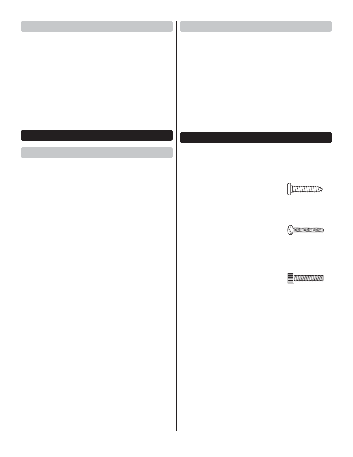
● There are three types of screws used in this kit:
Sheet Metal Screws are designated by a number and a
length. For example #6 × 3/4" [19mm].
This is a number six screw that is
3/4" [19mm] long.
Machine Screws are designated by a number, threads
per inch, and a length. For example
4-40 × 3/4" [19mm].
This is a number four screw that
is 3/4" [19mm] long with forty
threads per inch.
Socket Head Cap Screws (SHCS) are designated by
a number, threads per inch, and a length. For example
4-40 × 3/4" [19mm].
This is a 4-40 SHCS that is 3/4"
[19mm] long with forty threads
per inch
● When you see the term test fi t in the instructions, it means
that you should fi rst position the part on the assembly
without using any glue, then slightly modify or custom fi t
the part as necessary for the best fi t.
● Whenever the term glue is written you should rely upon
your experience to decide what type of glue to use. When
a specifi c type of adhesive works best for that step, the
instructions will make a recommendation.
● Whenever just epoxy is specifi ed you may use either
30-minute (or 45-minute) epoxy or 6-minute epoxy. When
30-minute epoxy is specifi ed it is highly recommended that
you use only 30-minute (or 45-minute) epoxy, because you
will need the working time and/or the additional strength.
● Photos and sketches are placed before the step they refer
to. Frequently you can study photos in following steps to
get another view of the same parts.
4
Page 5
● The Yak-55M is factory-covered with Top Flite® MonoKote®
fi lm. Should repairs ever be required, MonoKote can be
patched with additional MonoKote purchased separately.
MonoKote is packaged in six-foot rolls, but some hobby
shops also sell it by the foot. If only a small piece of MonoKote
is needed for a minor patch, perhaps a fellow modeler
would give you some. MonoKote is applied with a model
airplane covering iron, but in an emergency a regular iron
could be used. A roll of MonoKote includes full instructions
for application. Following are the colors used on this model
and order numbers for six foot rolls.
True Red (TOPQ0227) Black (TOPQ0208)
Jet White (TOPQ0204) Metallic Platinum (TOPQ0408)
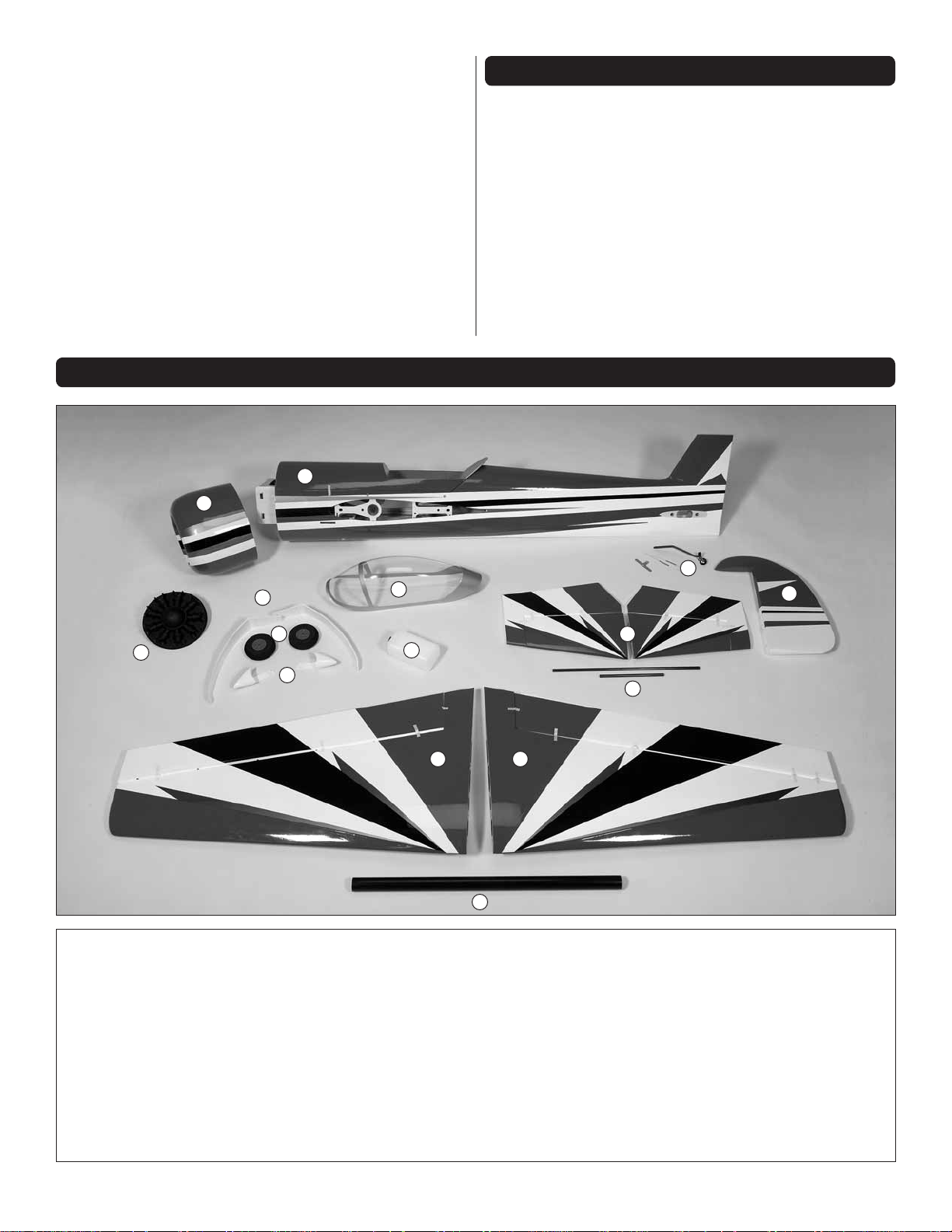
KIT CONTENTS
1
2
KIT IN SPE CTIO N
Before starting to build, take an inventory of this kit to make
sure it is complete, and inspect the parts to make sure they
are of acceptable quality. If any parts are missing or are not
of acceptable quality, or if you need assistance with assembly,
contact Pr oduct Support. When reporting defective or missing
parts, use the part names exactly as they are written in the
Kit Contents list.
Great Planes Product Support
3002 N Apollo Drive, Suite 1 Ph: (217) 398-8970, ext. 5
Champaign, IL 61822 Fax: (217) 398-7721
E-mail: airsupport@greatplanes.com
12
1. Fuselage
2. Cowl
5
11
10
9
3
8
13 14
15
6. Rudder
7. Stabilizer Tubes
4
7
11. Landing Gear
12. Dummy Engine
6
3. Canopy
4. Stabilizers with Elevators
5. Tail Wheel Assembly
8. Fuel Tank
9. Wheel Spats
10. Wheels
5
13. Right Wing
14. Left Wing
15. Wing Tube
Page 6
ORDERING REPLACEMENT PARTS
Replacement parts for the Great Planes Yak-55M ARF are
available using the order numbers in the Replacement Parts
List that follows. The fastest, most economical service can be
provided by your hobby dealer or mail-order company.
To locate a hobby dealer, visit the Great Planes web site at
www.greatplanes.com. Select “Where to Buy” in the menu
across the top of the page and follow the instructions provided
to locate a U.S., Canadian or International dealer.
Parts may also be ordered directly from Hobby Services by
calling (217) 398-0007, or via facsimile at (217) 398-7721, but
full retail prices and shipping and handling charges will apply.
Illinois and Nevada residents will also be charged sales tax. If
ordering via fax, include a Visa® or MasterCard® number and
expiration date for payment.
Mail parts orders Hobby Services
and payments 3002 N Apollo Drive, Suite 1
by personal check to: Champaign IL 61822
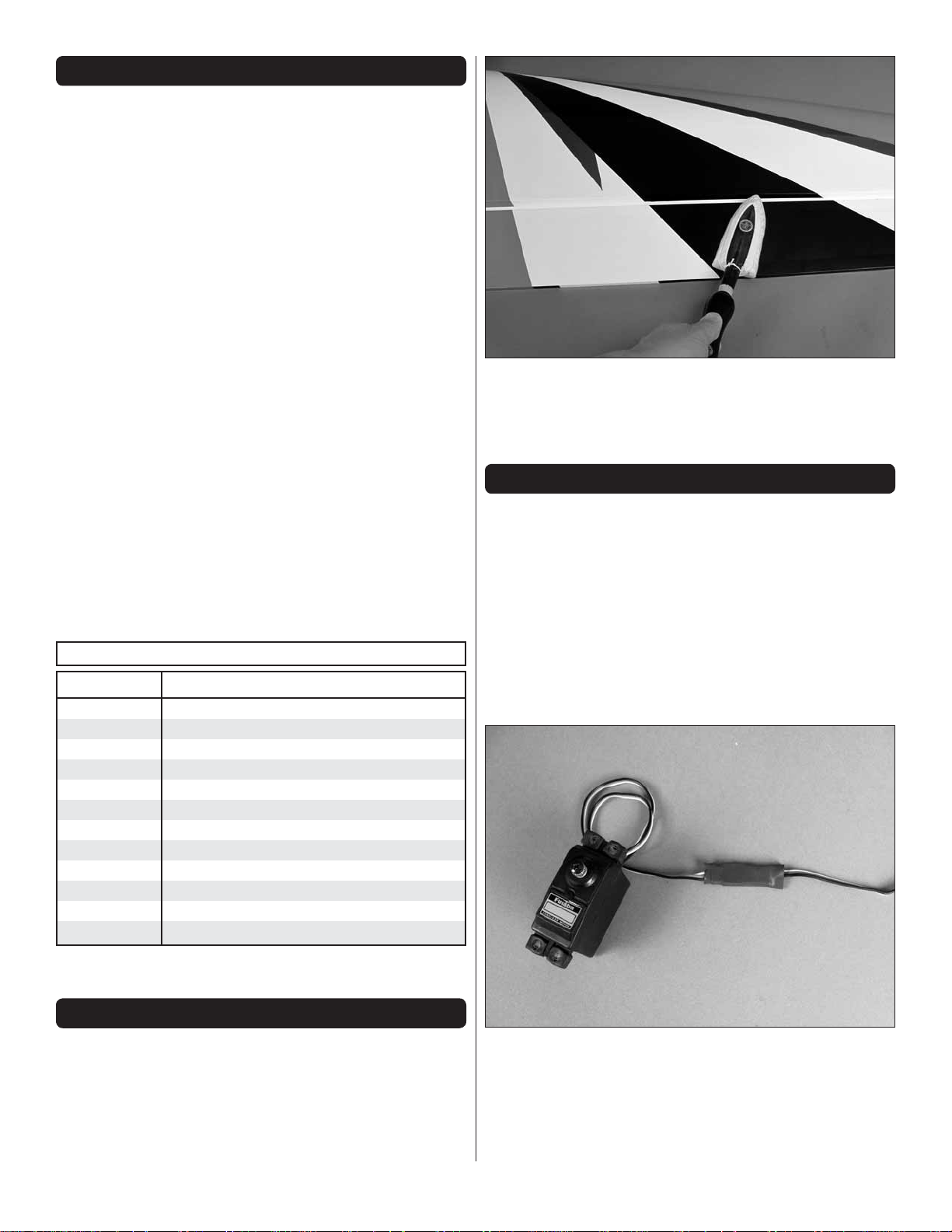
2. Use a covering iron with a covering sock on high heat
❏
to tighten the covering if necessary. Do this for all of the
components of the model. Apply pressure over sheeted areas
to thoroughly bond the covering to the wood.
Be certain to specify the order number exactly as listed in the
Replacement Parts List. Payment by credit card or personal
check only; no C.O.D.
If additional assistance is required for any reason contact
Product Support
by e-mail at productsupport@greatplanes.com
or by telephone at (217) 398-8970
REPLACEMENT PARTS LIST
Order No. Description
GPMA4050 Fuselage
GPMA4051 Wing
GPMA4052 Horizontal Stabilizers
GPMA4053 Rudder
GPMA4054 Cowl
GPMA4055 Landing Gear
GPMA4056 Gear Spats
GPMA4057 Canopy
GPMA4058 Canopy Hatch
GPMA4059 Tail Wheel Assembly
GPMA4060 Decals
GPMA4061 Wing Joiner Tube
ASSEMBLE THE WING
Note: Throughout this instruction manual you will be instructed
to use screws to secure different parts. In all cases, whene ver
a screw is threaded into wood sheeting or wood blocks, we
recommend that you install the screw and then remov e it. Apply
a drop of thin CA glue into the hole to harden the threads. After
the glue has hardened, re-install the screw. Following this
step will insure that you have a solid thread for your screws.
Whenever a screw is threaded into a blind nut or a nut is
installed onto a screw, it is recommended that you always
apply a drop of thread locker to them.
PREPARATIONS
1. If you have not done so already, remove the major
❏
parts of the kit from the box and inspect for damage. If any
parts are damaged or missing, contact Product Support at
the address or telephone number listed in the “Kit Inspection”
section on page 5.
Begin with your right wing panel fi rst so your assembly
matches the photos in the manual.
1. Install a 12" [305mm] servo extension to your aileron
❏ ❏
servo. Secure it with heat shrink tubing, tape or other method
for securing them together.
6
Page 7
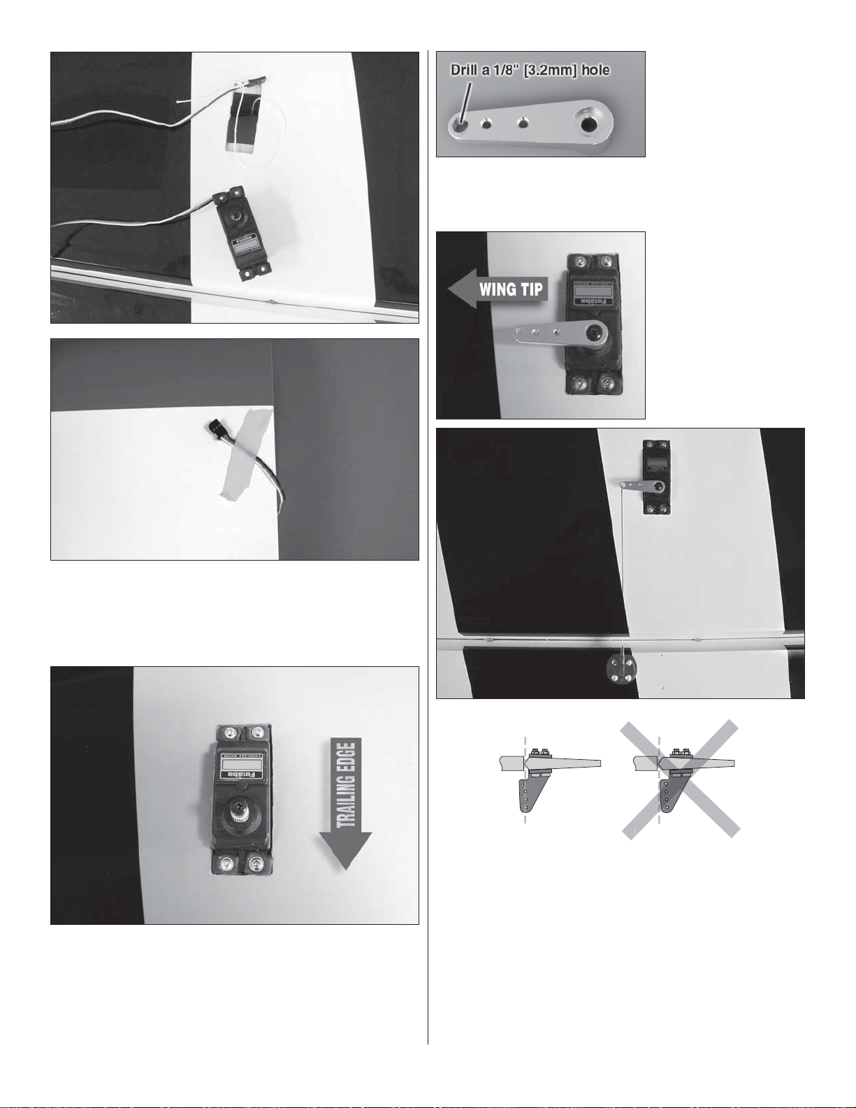
4. The aileron servo
Hi
❏ ❏
will require a 1" [25mm]
servo arm to get the
required aileron throw.
We recommend that a
high strength metal
servo arm be used. For
our model we used the aluminum Futaba arm (FUTM2120).
Open up the outermost hole in the servo arm by drilling a 1/8"
[3.2mm] hole through it.
5. Install the servo
❏ ❏
arm to the servo as
shown. Be sure to apply
thread locker to the
spline screw.
2. Inside the aileron servo compartment you will fi nd a
❏ ❏
string. Tie the string to the servo lead. The other end of the
string is taped to the root wing of the rib. Pull the leads through
the wing and then tape the servo lead to the wing to prevent
it from falling back into the wing.
3. Place your servo onto the mounting blocks. Drill a
❏ ❏
1/16" [1.6mm] hole through the servo mounting tabs into the
mounting blocks. Secure the servos to the mounting blocks
with the screws that came with your servos. Note: When
installing the servo into the wing, the end of the servo with the
spline should be located towards the trailing edge of the wing.
CORRECT INCORRECT
Hinge Line Hinge Line
6. Located in the aileron is a plywood mounting plate.
❏ ❏
If you look at the control surface at a slight angle you will be
able to see the plate through the covering. Draw a line from
the outer hole of the servo horn perpendicular to the hinge
line with a felt tip marker. Place a large nylon black control
horn on the plate, in line with the line you have drawn. Position
the control horn on the hinge line as shown in the illustration.
Drill a 3/32" [2.4mm] hole through each of the holes in the
control horn. Drill only through the plywood plate. Do not drill
through the top of the control surface. Mount the horn with
four #4 x 1/2" [13mm] screws.
7
Page 8
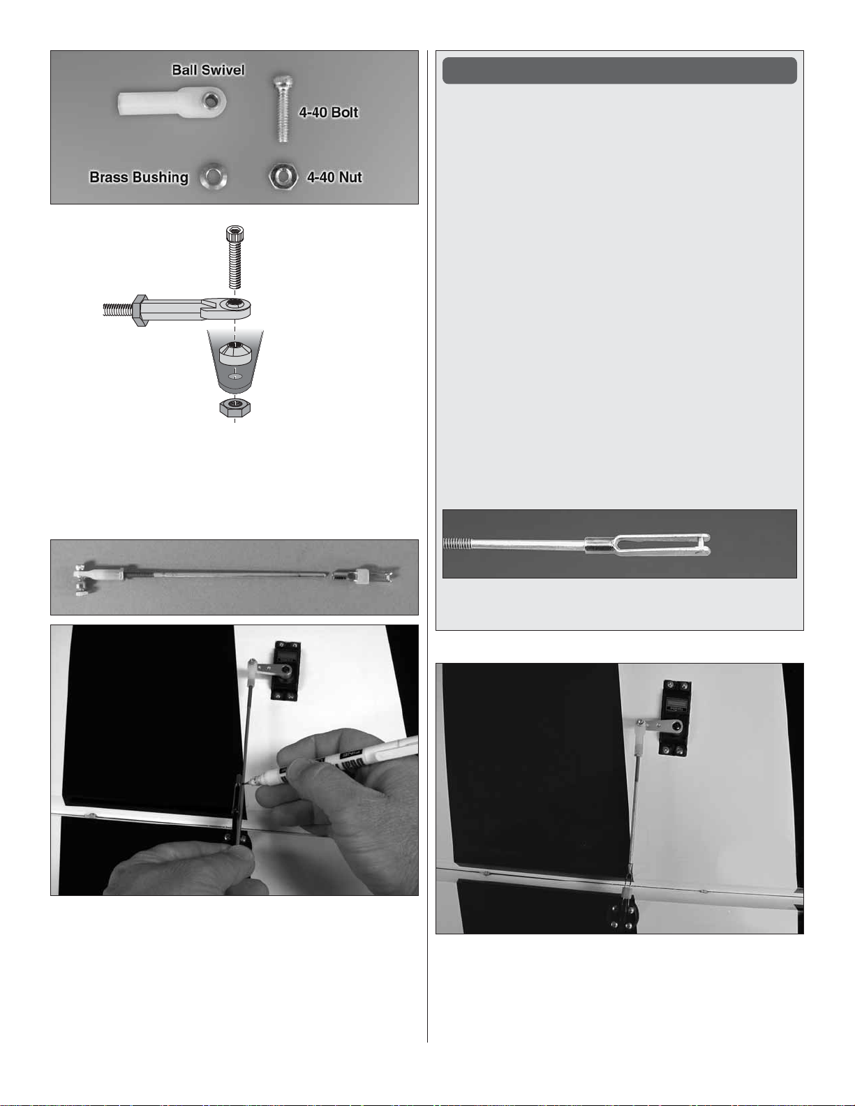
4-40 Bolt
Ball Swivel
4-40 Nut
Brass Bushing
4-40 Nut
7. Locate all of the components shown in the picture, a
❏ ❏
4-40 x 5 3/4" [146mm] pushrod wire and an additional 4-40 nut.
Examine the diagram that shows the proper way to assemble
the swivel ball link. Mount the swivel ball link into the hole you
drilled in the servo arm.
How to Solder
1. Use denatured alcohol or other solvent to thoroughly
clean the pushrod. Roughen the end of the pushrod with
coarse sandpaper where it is to be soldered.
2. Apply a few drops of soldering fl ux to the end of the
pushrod, then use a soldering iron or a torch to heat it.
“Tin” the heated area with silver solder by applying the
solder to the end. The heat of the pushrod should melt the
solder – not the fl ame of the torch or soldering iron – thus
allowing the solder to fl ow. The end of the wire should be
coated with solder all the way around.
3. Place the clevis on the end of the pushrod. Add another
drop of fl ux, then heat and add solder. The same as
before, the heat of the parts being soldered should melt
the solder, thus allowing it to fl ow. Allow the joint to cool
naturally without disturbing. Avoid excess blobs, but make
certain the joint is thoroughly soldered. The solder should
be shiny, not rough. If necessary, reheat the joint and allow
to cool.
4. Immediately after the solder has solidifi ed, but while it
is still hot, use a cloth to quickly wipe off the fl ux before
it hardens. Important: After the joint cools, coat the joint
with oil to prevent rust. Note: Do not use the acid fl ux that
comes with silver solder for electrical soldering.
8. The photo shows how your pushrod assembly should
❏ ❏
look. Center the aileron and the aileron servo. Install the servo
arm onto the servo and the solder clevis into the second most
outer hole of the control horn. Mark where to cut the pushrod
wire. Cut the wire on the mark you made. Remove all of the
components of the pushrod wire from the clevises and the
control horn. Solder the pushrod wire to the solder clevis using
the soldering “Hot Tip” that follows.
This is what a properly soldered clevis looks like –
shiny solder with good flow, no blobs and flux removed.
9. After the solder cools, install the pushrod assembly
❏ ❏
to the aileron servo and the aileron. Be sure to use thread
locker on the nuts and a silicone clevis keeper on the clevis.
8
Page 9
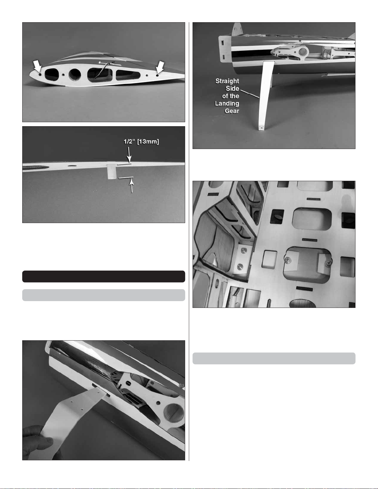
10. Glue a 5/16" x 1" [7.9mm x 25mm] wood dowel into
❏ ❏
the two outermost holes in the wing root. The dowel should
extend out of the wing 1/2" [13mm].
11. Repeat steps 1- 10 for the left wing panel.
❏
ASSEMBLE THE FUSELAGE
Install the Main Landing Gear
The following steps explain mounting the main landing gear.
We will fi nish the tail wheel gear and installation of the wheels
later in the manual. You will fi nd the fuselage much easier to
work with when the landing gear is installed.
1. Slide the landing gear into the fuselage on both the left
❏
and right side of the fuselage. The straight side of the landing
gear should be towards the front of the fuselage.
2. Secure the landing gear with 8-32 x 3/4" SHCS, #8 lock
❏
washers and #8 fl at washers. Be sure to apply thread locker
to the screw threads.
Install the Stabs & Elevators
1. Including the servo lead from the servo, you will need
❏
58" [1475mm] of wire to reach from the elevator to the radio
compartment in the airplane. For a Futaba servo this means
you will need some combination of servo leads to equal 45"
[1145mm] or more. We used a 12" [305mm] and 36" [914mm]
lead plugged together. Be sure to secure all of the connections
with heat shrink tubing, tape or some other method to secure
all of the connections. If you have the ability make your own
leads you may choose to do this and eliminate one of the
connections. Make two of these extensions. Install the rubber
servo pads and metal grommets on the servos.
9
Page 10
2. To achieve proper elevator control
❏ ❏
you will need to use a 1-1/2" heavy duty servo
arm. We used the Futaba aluminum arm
(FUTM2118). Enlarge the hole that is 1-1/4"
[32mm] from the center of the servo spline
with a 1/8" [3.2mm] drill. (The 1-1/4" [32mm]
dimension is approximate. You may fi nd that
for your brand of servo, the holes might be
spaced slightly different than the Futaba.
Open up the hole closest to this dimension.)
6. Guide the servo lead through the stab exiting through
❏ ❏
the root rib. Secure the servo cover in place with four #2 x 3/8"
[9.5mm] screws and #2 fl at washers.
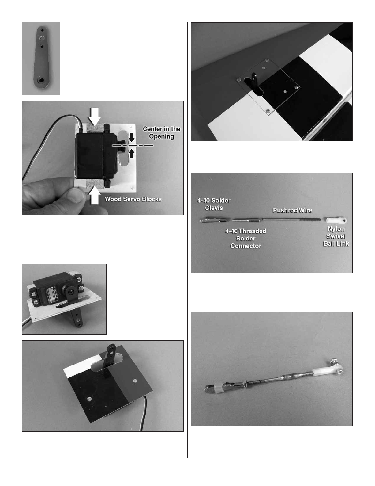
3. Center your servo and then install the arm to the servo.
❏ ❏
Remove the servo tray cover from the left stab. Place the
servo on the tray with the servo arm centered in the slot. Glue
a 5/16" x 9/16" x 13/16" [8mm x 14mm x 21mm] wood servo
block on each side of the servo.
4. Drill a 1/16" [1.6mm]
❏ ❏
hole through each of the
mounting tabs of your servo.
Mount the servo with the
hardware that came with
your servos.
7. Cut one of the 4-40 x 5-3/4" [146mm] pushrod wires
❏ ❏
to a length of 2-3/4" [70mm]. Using the solder technique used
on the ailerons, solder the unthreaded end of the wire to the
4-40 threaded solder connector.
5. Drill a 1/16" [1.6mm] hole through the servo cover
❏ ❏
into the hardwood blocks you glued in place. Install a #2 x 3/8"
[9.5mm] wood screw into each block to secure them.
8. Assemble the pushrod as shown in the photo. Be sure
❏ ❏
to use thread locker on the nuts when doing the fi nal assembly.
Install the nylon swivel ball link to the servo arm with a 4-40
x 1/2" [13mm] screw and 4-40 nut.
10
Page 11

CORRECT INCORRECT
Hinge Line Hinge Line
9. Using the pushrod wire as a guide, locate the plywood
❏❏
plate in the elevator servo. Position the large nylon black control
horn on the plate, in line with the pushrod wire. Position the
control horn on the hinge line the same way you did for the
ailerons. Drill a 3/32" [2.4mm] hole through each of the holes
in the control horn. Drill only through the plywood plate. Do
not drill through the top of the control surface. Mount the
horn with four #4 x 1/2" [13mm] screws.
12. Locate the two carbon fi ber stab tubes. Slide the shorter
❏
length tube into the forward most hole in the rear of the fuselage
and the longest tube in the rear hole in the fuse. Through the
opening in the back of the fuselage, install the servo leads
into the fuselage up to the radio compartment and then test
fi t the stabs to the fuselage.
10. Install the servo pushrod as shown. Make any
❏ ❏
adjustments required to the arm to get the proper length for
the pushrod so when the servo is centered, the elevator is
aligned with the stabilizer.
11. Repeat steps 2-10 for the right side stabilizer / elevator.
❏
13. When you are satisfi ed with the fi t, glue the stabs
❏
one side at a time to the fuselage with 30-minute epoxy.
Apply the glue to the tubes, the root rib of the stab and the
fuselage side. Clean any excess epoxy with a paper towel
and rubbing alcohol. Use masking tape to hold the stabs
tight to the fuselage while the glue is curing.
11
Page 12

Install the Rudder
Install the Rudder Servos
1. Without using any
❏
glue, install four hinges
into the holes in the
trailing edge of the rudder.
Note that the pivot point
of each hinge must align
with the center of the
trailing edge. To achieve
this alignment, the hinges
will be fairly deep in the fi n.
Also note that the hinges
must be perpendicular to
the leading edge.
2. Again without glue,
❏
test fi t the rudder to the fi n. Remove the rudder and all the
hinges. Add a small drop of oil to the pivot point on the hinges.
This will prevent the epoxy from adhering to the pivot point.
Make sure oil does not get on the gluing surface of the hinge.
If it does, clean the oil off with a paper towel square dampened
with denatured alcohol.
3. Mix up approximately 1/4 oz. [7.4cc] of 30-minute epoxy.
❏
Use a toothpick to thoroughly apply the epoxy in the holes in
the fi n and rudder. Use the toothpick to get the epoxy out of
the opening of the holes in the rudder and fi n so it doesn’t get
into the hinge pin. Wipe away any excess epoxy around the
outside of the holes with a couple of the small paper towel
squares dampened with denatured alcohol.
We have designed this airplane with the option to use one servo
with 250 oz-in. of torque or to use two, lower strength servos
in tandem. If you are more of a sport fl yer and not an aspiring
3-D pilot, you can use a single servo with approximately 125
oz-in. You will need to make a decision on the number of
servos you will be using. Should you decide to use a single
servo and later decide you would like to use two servos you
can add the second servo later.
4. Use the toothpick to apply epoxy to the ends of the rudder
❏
hinges that go into the fi n. Insert each hinge into the fi n and
wipe away any excess epoxy that squeezes out of the hole.
5. Apply epoxy to the other end of the hinges. Join the
❏
rudder to the fi n, pushing the hinges only about 3/4 of the
way into the rudder. Use a toothpick to wipe away any epoxy
that squeezes out. Then fi t the rudder the rest of the way in.
6. Move the rudder left and right to align the hinges. If
❏
needed, use a length of masking tape to hold the rudder to
the fi n. Allow the glue to fully cure.
1. Modify two large black nylon control horns as shown.
❏
This is easily completed with a high speed motor tool, small
belt sander or a sanding block with coarse sandpaper. As
you did with the ailerons horns, locate the plywood plate on
each side of the rudder. Position the horns over the plates.
Drill a 3/32" [2.4mm] hole through each of the holes in the
control horn. Drill only through the plywood plate. Do not
drill through the control surface. Mount the horn with four
#4 x 1/2" [13mm] screws. Do this on both sides of the rudder.
SINGLE SERVO INSTALLATION
If you will be installing two servos, skip ahead to, “Two
Servo Installation”.
2. For the rudder
❏ ❏
servo arm installation
you will need one of
the aluminum servo
arms included in the kit
and one of the round
servo disks included
with your radio system.
The round servo disk
needs to be at least 1"
[25mm] in diameter.
12
Page 13

3. Position the aluminum servo arm on top of the disk.
❏ ❏
Drill a 3/32" [2.4mm] hole through the aluminum arm and
through the disk. Do this for all four holes. Secure the arm to
the disk with four 2-56 x 1/2" [13mm] machine screws and
2-56 nuts. Be sure to secure the nuts with a drop of thread
locker. After the nuts are secure, cut off the thread from the
bolt that extends above the nut. This can be done with a high
speed motor tool or a good side cutter.
7. Use pliers to pull the cable from the fi rst loop to reduce
❏ ❏
the size of the second loop. Squeeze the swage with pliers
and then cut off the excess wire.
8. Repeat steps 2 – 7 for the remaining cable.
❏
9 Install a 4-40 thread clevis, 4-40 nut and a silicone clevis
❏
keeper onto the threaded connectors.
4. Install your servo into the rear rudder servo tray using
❏ ❏
the hardware that came with your servo. Center the servo and
then install the servo arm.
5. Use wire cutters to cut the supplied braided cable into
❏ ❏
two equal lengths. Slide a small tube (called a swage) over the
end of one cable. Then, guide the end of the cable through
the threaded brass coupler and the back through the swage.
6. Wrap the cable back around the swage and back
❏ ❏
through the swage.
10. Inside of the fuselage are two white plastic guide tubes.
❏
Slide a wire into each of the tubes until they exit out the
fuselage sides. Connect the clevis to the hole in the aluminum
servo arm. Note: When you connect the clevises to the arm
be sure that the wires cross each other. In other words, the
wire attached to the right side of the servo arm exits the left
side of the fuselage and the left side clevis exits out the right
side of the fuselage.
If you have completed the single servo installation, skip ahead
to, “Complete the Rudder Control Installation”.
13
Page 14

DOUBLE SERVO INSTALLATION
1. For the dual rudder
❏ ❏
servo arm installations
you will need two of the
aluminum servo arms
included in the kit and two
of the round servo disks
included with your radio
system. The round servo
disk needs to be at least 1"
[25mm] in diameter.
2. Position the aluminum servo arm on top of the disk.
❏ ❏
Drill a 3/32" [2.4mm] hole through the aluminum arm, through
the disk. Do this for all four holes. Secure the arm to the disk
with four 2-56 x 1/2" [13mm] machine screws and 2-56 nuts.
Be sure to secure the nut with a drop of thread locker. After the
nuts are secure, cut off the thread from the bolt that extends
above the nut. This can be done with a high speed motor tool
or a good side cutter. Do this for both servo arms.
5. Locate four heavy duty screw lock connectors, metal
❏ ❏
retainer clips and 4-40 x 1/4" [6mm] socket head cap screws.
Install the connector into the outer hole of the servo arms and
secure them with the retainer clips. Center both servos and
then install the two 4-40 wires into the connectors. Secure
the rods with the 4-40 screws. Be sure to apply a couple of
drops of thread locker to each screw.
6. Use wire cutters to cut the supplied braided cable into
❏ ❏
two equal lengths. Slide a small tube (called a swage) over the
end of one cable. Then, guide the end of the cable through
the threaded brass coupler and the back through the swage.
3. Install your servos into the rudder servo tray using
❏ ❏
the hardware that came with your servo. Center the servos
and then install the servo arm.
4. Locate two 4-40 x 5-3/4" [146mm] thread pushrod wires.
❏ ❏
Cut off the threaded end of the wire leaving an unthreaded
wire 3-1/2" [89mm] in length.
14
7. Wrap the cable back around and through the swage.
❏ ❏
Page 15

8. Use pliers to pull the cable from the fi rst loop to reduce
❏ ❏
the size of the second loop. Squeeze the swage with pliers
and then cut off the excess wire. Do this for both wires.
9. Install a 4-40 thread clevis, 4-40 nut and a silicone
❏ ❏
clevis keeper onto the threaded connectors.
2. Adjust the tension of the wires by turning the clevises in
❏
or out on the connector. Then, lock the nut against the clevis.
Be sure to apply a drop of thread locker to the nut.
Install the Engine
The following instructions cover the installation of the DLE55.
Other engines will require similar installation. You will need to
determine the proper mounting hole positions and location for
the throttle connections for your choice of engine.
MOUNT THE ENGINE AND INSTALL THE THROTTLE
AND CHOKE SERVOS
The following instructions will show how to install a servo
activated choke. We know some modelers may wish to use
some sort of a manual linkage. It is recommended that you
read the installation instructions and then decide which method
you prefer. We will not be showing installation of a manual
linkage. Most modelers will fi nd that this is easy to do and
requires little explanation.
10. Inside of the fuselage are two white plastic guide
❏ ❏
tubes. Slide a wire into each of the tubes until they exit out the
fuselage sides. Connect the clevis to the hole in the aluminum
servo arm. Note: When you connect the clevises to the arm,
be sure that the wires cross each other. In other words, the
wire attached to the right side of the servo arm exits the left
side of the fuselage and the left side clevis exits out the right
side of the fuselage.
Complete the Rudder Control Installation
1. Attach a clevis to the outer hole of the rudder control
❏
horns that you modifi ed. Center the rudder and the rudder
servo. Attach the wire to each of the clevis assemblies and
then secure the wire with the swages using the same technique
used on the connection at the servo.
1. Locate the paper mounting pattern on page 32 of this
❏
manual. Tape the pattern to the fi rewall, aligning the reference
lines on the paper pattern with the reference lines on the
fi rewall. When positioning it, the bolt hole pattern should be
aligned as shown.
2. Drill a 1/8" [3.2mm] pilot hole through the center of each
❏
mounting hole. Remove the paper pattern and drill a 13/64"
[5.2mm] hole through the fi rewall on each of the pilot holes
15
Page 16

you drilled. (13/64 [5.2mm] is required as a clearance hole for
a 10-24 bolt. If you are mounting a different engine, be sure to
check the size of the mounting bolts before drilling the holes).
3. Install the fi ber servo arm to the carburetor of the engine.
❏
Install a 2-56 ball link and secure it with a 2-56 nut on the
throttle. If you will be using our choke method, then install a
ball and nut to the choke as well.
removing the engine. If not you will need to remove and then
reinstall the engine.
6. Locate two 1/4" x 3/8" x 3/4" [6mm x 10mm x 19mm]
❏
hardwood blocks. Glue them in place over the choke servo
opening as shown.
4. Using the hardware with the engine, mount the engine
❏
to the fi rewall.
5. Cut one half off of one of the two nylon ball links included
❏
in the kit. Snap the nylon link that you cut onto the choke
and the remaining nylon link onto the throttle. Use the links
as reference and mark the fi rewall where the pushrods will
pass through. Drill a 3/16" [4.8mm] hole through each of the
marks. If you have an extended drill bit you can do this without
7. Mount the throttle and choke servos as shown here. If
❏
you are not using a choke servo you can mount the throttle
servo in either of the two openings.
8. Locate the plywood guide tube support and two 12"
❏
[305mm] gray plastic pushrod tubes. Roughen approximately
16
Page 17

1" [25mm] on one end of each of the tubes with 200 grit
sandpaper. Insert the tubes into the hole you drilled in the
fi rewall. Be sure to insert the smooth end of the tube fi rst so
that the roughened end contacts the fi rewall. Apply glue to
the roughened end of the tubes and then make the end of
the tube fl ush with the fi rewall.
9. Slide the plywood guide tube support over both tubes.
❏
(If you are not installing the choke servo then just slide the
tube over the single pushrod tube.) Slide it forward until it is
at the former as shown. Do not glue the support in place!
Cut the tubes so that they end approximatey 2" [51mm] before
the servo arms.
11. Cut the inner white nylon pushrod to the proper length for
❏
the position of the servos. Install a 2-56 x 1" [25mm] threaded
rod into the end of the pushrod tube followed by a 2-56 nut
and a 2-56 metal clevis and silicone clevis keeper. When you
are satisfi ed with the installation, glue the plywood guide tube
to the bulkhead. Position it so that the tubes make as straight
an exit through the fi rewall as possible.
Install the Fuel Tank
10. Thread a 2-56 x 1" [25mm] threaded rod into the end
❏
of two white nylon inner pushrod tubes (You only need to do
one tube if you are not using the servo activated choke) and
then screw the nylon ball link connectors to the wires. Slide
the pushrods into the plastic tubes you glued to the fi rewall.
Snap the ball links onto the balls. Be sure that you use the
pushrod with the shortened ball link for the choke.
1. Assemble the fuel tank stopper assembly with the fuel
❏
tubes as shown. The easiest way is to fi rst solder a fuel line
barb (not included, Dubro Fuel Line Barb DUB0670) at the
17
Page 18

end of all three tubes. Insert the tubes into the stopper with the
metal plates, and then solder a barb onto the other end of the
two short tubes. Bend the vent tube and connect the pickup
and gas compatible fueling/defueling lines (not included) to
the short tubes. Connect the clunks to the Tygon Fuel lines
(not included) and secure the lines to the clunk and brass
tubing with the included small tie straps.
2. Install the fuel tank stopper assembly in the fuel tank.
❏
Check that the clunks move around freely in the fuel tank.
Tighten the fuel tank stopper screw.
3. Install fuel lines onto the brass tubes from the fuel tank.
❏
To route the fuel lines where shown, you will need to use a
12" [305mm] length of tubing on the fi ll and vent line and a 6"
[152mm] length on the carburetor line.
4. Drill a 1/4" [25mm] hole through the fi rewall in line with
❏
the carburetor inlet.
6. Route the carburetor line through the fi rewall, trim it as
❏
needed and attach it to the carburetor. Drill two 1/4" [25mm]
holes through the bottom of the fi rewall box as shown. Pass
the vent and fi ll lines through the holes. To secure the fi ll and
vent line we drilled additional holes in the fuselage. You may
wish to do this or secure the lines with a method of your choice.
Plug the fi ll line with the aluminum fuel plug.
5. Install the fuel tank onto the tray in the fuselage. Secure
❏
the tank with two large plastic tie wraps. Feed the lines through
the fi rewall. Make sure when you insert the tank that the vent
line is at the top of the tank.
7. Install the ignition battery and module following the
❏
instructions with the engine. We have provided four hooks for
securing the module and battery. Be sure to secure all of the
electrical connections between the ignition module, battery
and switch harness. Mount the ignition switch and charge jack
to the fuselage side. We used an Ernst Futaba charge jack
(ERNM3001) for our installation.
INSTALL THE MUFFLER
This airplane is designed to allow you the fl exibility of installing
your choice of a Pitts style muffl er, canister or a tuned pipe.
For purposes of this manual we will show the full installation
of the canister muffl er system and give an overview of the
requirements to install the tuned pipe and Pitts muffl er. You
need to decide which system you will use. You might wish to
review the installation instructions before determining which
option is best for you.
18
Page 19

Pitts Style Muffler Installation
Canister Muffler Installation
1. Remove the two covers from the bottom of the fuselage.
❏
These two covers allow you to customize the fuselage for your
choice of muffl er, canister or tuned pipe. For a canister, glue
the rear cover in place to the fuselage.
1. Remove the two covers from the bottom of the fuselage.
❏
If you will be using the muffl er that came with your engine
or using a Pitts style muffl er, permanently glue the covers
to the fuselage. If you have thoughts of changing between a
Pitts style muffl er and a canister, you might choose to glue
the covers in place with silicone. This would allow the covers
to be cut loose at a later time.
2. The kit includes 4 plywood canister/pipe holder and one
❏
24" [610mm] piece of silicone tubing. For the canister you will
be using two of the holders. From the 24" [610mm] silicone
tube, cut eight 1/2" [13mm] length tubes. (The remaining
holders and silicone tubing are for use with the installation of
a tuned pipe). When choosing the plywood holders, notice that
one is slightly taller than the other. You will need one of each.
2. Mount the muffl er to the engine. Be sure the spark plug
❏
lead from the ignition module is not contacting the muffl er.
3. Insert eight silicone tubes onto the tabs in the two plywood
❏
holders as shown.
19
Page 20

4. Gather all of the canister components together. Test fi t
❏
the canister to the holders. The taller of the plywood holders
should be at the front of the canister and the shorter holder
towards the rear. The canister should fi t slightly loose between
the silicone holders.
6. Test fi t the canister and holders into the opening in the
❏
fuselage. When you are satisfi ed everything fi ts well, remove
the canister and remove the holders from the canister.
7. Insert the taller of the two holders into the fuselage. Glue
❏
it on the seam where the plywood meets balsa wood. Glue
the shorter holder in place 7" [187mm] back from the forward
holder. Make supports for the holders from the 1/4 x 1/4 x 24"
[6mm x 6mm x 610mm] balsa stick included in the kit. Cut
the sticks to length to fi t the holders. Glue the sticks to the
holders and the tunnel wall. The canister holders are already
fuel proofed but you should take a few minutes to fuel proof
the sticks. This can be done by brushing a small amount of
epoxy over the bare wood.
5. Temporarily mount the exhaust header to the engine.
❏
8. Slide the canister into the holders. Slide the coupling
❏
and the clamps onto the exhaust header and the secure the
header to the engine. Slide the coupler in place so that there
is approximately 1/4" [6mm] between the end of the canister
and the exhaust header. Be sure that the end of the canister
does not hit the back of the tunnel. You need to leave room
for the canister to expand when it gets hot. Be sure the lead
from the ignition module is not contacting the muffl er.
20
Page 21

Tuned Pipe Installation
MOUNT THE COWLING
AND DUMMY ENGINE
1. The kit includes six 5/8" x 5/8" x 3/4" [16mm x 16mm x
❏
19mm] hardwood cowl mounting blocks. Depending on the
muffl er you chose to mount, you may not choose to use all
of the blocks. As shown for the canister installation we glued
fi ve of the blocks to the front of the fuselage as shown here.
Determine how many of the blocks you will use and where they
will be positioned. Then, glue them to the fi rewall with epoxy.
After the epoxy has cured be sure to fuel proof the blocks.
1. Remove all of the covers from the bottom of the fuselage.
❏
Glue the balsa fl oor and side walls in place in the back of
the tunnel.
2. Refer to the instructions for the canister. The procedure
❏
is the same except that you will use four pipe holders instead
of two that are used for the canister installation.
2. On the back side of the fi rewall make reference marks
❏
for the location of the blocks. On the remaining blocks, tape
a piece of masking tape over the block, extending back onto
the fuselage. From the center of the block make a line 1"
[25mm] long.
21
Page 22

3. Install the cowl onto the fuselage. The cowl should over
❏
lap the fi rewall approximately 1/8" [3.2mm]. Using the lines
you drew on the blocks, measure forward 1" from the mark
you made. Drill a 3/32" [2.4mm] hole through the cowl and the
block. Use the reference marks you made on the back of the
fi rewall to locate the blocks and drill a hole. Do this for all of
the cowl mounting blocks. Install and then remove a #4 x 1/2"
[13mm] screw into each of the holes you made. Apply a drop
of thin CA to harden the threads. Allow the glue to harden.
6. To allow cooling air to fl ow over the engine cylinder
❏
you need to cut the dummy engine as shown. This allowed
enough cooling air for our installation. Should you fl y in hotter
conditions or use the minimum amount of oil required for the
engine, you may also wish to cut away the dummy engine
cylinder to allow more airfl ow.
4. Locate the aluminum cowl mounting disks. Sand one
❏
side of each disk with 220 grit sandpaper and then clean
them with alcohol. Lightly sand inside the cowl at each of the
mounting holes. Clean the area with alcohol. Using 5-minute
epoxy, glue a disk to the cowl at each of the mounting holes
you drilled. Be sure to align the hole in the disk with the hole
you drilled in the cowl.
5. Drill 1/8" [3.2mm] holes in the dummy engine to accept
❏
the 1/8" x 2-1/2" [3.2mm x 64mm] aluminum tubes. Insert
the tubes into the holes in the dummy engine. On the back
side of the dummy engine apply epoxy to the tubes to secure
them in place.
7. Place the dummy engine into the cowl. Mount the cowl
❏
to the fuselage with the cowl mounting screws. Thread a #64
rubber band through the aluminum tubes in the dummy engine
on the top and bottom half of the engine. Slide a balsa stick
through the rubber bands and place the sticks against the
cowl. (If you chose not to install the tuned pipe you will have
a 1/4" x1/4" x24" balsa stick left over. Cut the stick in half. If
you have used the stick you will need to provide a stick to
complete the installation) This will pull the dummy engine tight
to the inside of the cowl. Position the cowl where it needs to
be located. Once you have it properly positioned, carefully
remove the cowl.
8. Using thick CA, tack glue the dummy engine to the cowl
❏
in several spots. Re-install the cowl to verify the position of
the dummy engine. Make any additional adjustments / cutting
away of the dummy engine to achieve a good fi t. Once you are
22
Page 23

satisfi ed, permanently glue the dummy engine to the cowl. The
dummy engine needs to be glued to the cowl with a mixture of
5-minute epoxy and micro balloons. The addition of the micro
balloons will prevent the glue from running.
9. In order to provide suffi cient cooling to the engine you
❏
must provide openings for the air to exhaust out of the cowl. If
you installed either the canister or tuned pipe there is suffi cient
exhaust provided by the tunnel. If you are using the Pitts style
muffl er you will need to provide an opening in the bottom of
the cowl approximately 3-1/2" x 3-1/2" [89mm x 89mm].
INSTALL THE MAIN & TAIL WHEELS
1. Cut each of the 2" [52 mm] long axles to a length of
❏ ❏
1-5/8" [42mm]. Make a fl at spot in the end of the axle. This can
be done with a small fi le or high speed motor tool.
4. Install a 6-32 set screw into each of two 3/16" [5mm]
❏ ❏
wheel collars. Be sure to apply a drop of thread locker to each
of the set screws. Slide one wheel collar onto the axle followed
by the wheel and another wheel collar. Tighten the set screw
on the inner wheel collar against the axle and the set screw
in the outer wheel collar against the fl at spot you made in the
axle. Do this for both the left and right landing gear.
2 Install the axles to the landing
❏ ❏
gear with the large axle nuts.
5. Place the aluminum “T” bracket onto the bottom of the
❏ ❏
rudder as shown. Drill a 3/32" [2.4mm] hole through the two
center mounting holes, into the rudder. Remove the bracket
from the rudder. Insert and then remove a #4 x 1/2 [13mm]
screw into each of the holes. Apply a couple of drops of thin
CA glue into the holes to harden the threads. After the glue
has cured secure the bracket to the rudder with the screws.
3. Secure the wheel spats to the landing gear with three
❏ ❏
4-40 x 1/2" [13mm] screws and 4-40 lock nuts. Do this for
both landing gear.
23
Page 24

6. At the rear of the fuselage you will fi nd two small
❏ ❏
pilot holes. Drill a 3/32" [2.4mm] hole through the two holes.
Insert and then remove a #4 x 1/2 [13m] screw into each of
the holes. Apply a couple of drops of thin CA glue into the
holes to harden the threads. Mount the tail wheel bracket to
the fuselage with the screws and a #4 fl at washer and lock
washer. Center the rudder servo and the rudder. Attach a
spring to each side of the control horn.
1. Locate the three plywood parts shown. These will become
❏
the servo / battery tray. Glue two 1/4" x 1/4" x 5/8" [6mm x
6mm x 15mm] hardwood blocks to both of the plywood parts
as shown. The blocks should be installed even with the corners
of the part.
COMPLETE THE RADIO INSTALLATION
The following instructions explain installation of a tray for
mounting the battery and receiver. We found that for 3D fl ying
we added a small amount of tail weight to achieve the best
balance for this type of fl ying. If that is your intention for this
airplane, you may wish to try to mount the battery/receiver
further back into the fuselage rather than adding any weight
to the tail.
2. Glue the two side pieces into the slots in the tray inside of
❏
the fuselage. Once the glue has hardened, place the remaining
24
Page 25

part on top of them as shown. Drill a 1/16" [1.6mm] hole through
the holes in each corner of the top piece and into each of the
blocks. Insert and then remove a #2 x 3/8" [9.5mm] screw into
each of the holes. Apply a couple of drops of thin CA glue
into the holes to harden the threads. After the glue has cured
secure the top of the tray with four #2 x 3/8" [9.5mm] screws
and #2 fl at washers.
INSTALL THE CANOPY, PILOT
AND INSTRUMENT PANEL
1. Glue the two 1/4"x 3/4" [6mm x 19mm] dowels into the
❏
front of the fuselage hatch. The dowels should extend from
the front of the hatch 1/2" [13mm].
3. Cut the Velcro straps included with the kit to the proper
❏
length to secure your battery and receiver. Install both the
battery and the receiver onto foam and secure them with the
Velcro. For our installation we installed the battery under the
tray and installed the receiver on top. However, you may install
the components in either location.
2. Cut the instrument panel decal and then put it place in
❏
the front of the cockpit.
4. Install the radio switch harness and charge jack into the
❏
side of the fuselage. Be sure to leave at least 8" between the
radio switch and any of the components of the engine and
the ignition system, including the ignition switch.
5. Make all of the servo connections with the receiver. Secure
the battery connection to the switch lead with tape, heat shrink
tubing or some other method for securing the wires.
3. If you will be installing a pilot, install it securely in the
❏
cockpit.
25
Page 26

4. Attach the canopy hatch to the top of the fuselage with
❏
four 4-40 x 3/4" [19mm] screws, #4 lock washers and #4
fl at washers. Test fi t the canopy to the top of the fuselage to
determine the mounting position.
5. Determine the position of the canopy and make a couple
❏
of reference marks on the fuselage so that you can easily
locate the canopy position. Remove the canopy and apply a
bead of RC 56 glue to the inside of the canopy. Note that the
canopy rests on both the canopy hatch and the fuselage. You
only want the glue to be applied to the canopy where it
will be in contact with the canopy hatch. Tape the canopy
to the canopy hatch. Be sure the tape is only applied to the
hatch and not the fuselage below the hatch.
6. Remove the screws holding the canopy hatch in place
❏
and remove the hatch from the fuselage being careful not to
disturb the canopy.
7. Clean any excess glue that may have gotten on the
❏
fuselage or the back portion of the canopy with a damp cloth.
When you have removed the excess glue, reinstall the canopy
onto the fuselage. IMPORTANT! Be sure that you reinstall all
four of the screws that secure the canopy hatch. The hatch
must be tight to the fuselage while the glue dries. If needed,
add additional tape to secure the canopy. Allow the glue to
dry at least 12 hours.
8. Remove the canopy hatch from the fuselage. Mix a small
❏
amount of epoxy and micro balloons and make a small fi llet
of the glue on the back, underside of the canopy.
APPLY THE DECALS
1. Use scissors or a sharp hobby knife to cut the decals
❏
from the sheet.
2. Be certain the model is clean and free from oily fi ngerprints
❏
and dust. Prepare a dishpan or small bucket with a mixture
of liquid dish soap and warm water—about one teaspoon of
soap per gallon of water. Submerse the decal in the soap and
water and peel off the paper backing. Note: Even though the
decals have a “sticky-back” and are not the water transfer type,
submersing them in soap & water allows accurate positioning
and reduces air bubbles underneath.
3. Position decal on the model where desired. Holding the
❏
decal down, use a paper towel to wipe most of the water away.
4. Use a piece of soft balsa or something similar to squeegee
❏
remaining water from under the decal. Apply the rest of the
decals the same way.
26
Page 27

GET THE MODEL READY TO FLY
Proper Pushrod Hookup
Check the Control Directions
1. Turn on the transmitter and receiver and center the trims.
❏
If necessary, remove the servo arms from the servos and
reposition them so they are centered. Reinstall the screws
that hold on the servo arms.
2. With the transmitter and receiver still on, check all the
❏
control surfaces to see if they are centered. If necessary, adjust
the clevises on the pushrods to center the control surfaces.
4-CHANNEL RADIO SETUP (STANDARD MODE 2)
RIGHT AILERON
RUDDER
MOVES
RIGHT
FULL
THROTTLE
3. Make certain that the control surfaces and the carburetor
❏
respond in the correct direction as shown in the diagram. If any
of the controls respond in the wrong direction, use the servo
reversing in the transmitter to reverse the servos connected to
those controls. Be certain the control surfaces have remained
centered. Adjust if necessary.
MOVES UP
LEFT AILERON
MOVES DOWN
ELEVATOR
MOVES DOWN
AVOIDING FLUTTER, MAXIMIZING
SERVO OUTPUT TORQUE
SERVO ARM
OFFSET
Pivot point
CONTROL
HORN OFFSET
When connecting pushrods and setting up your control throws,
it is critically important to use proper pushrod geometry—
that is the distance from the pushrod on the servo arm to the
center of the output shaft (servo arm offset) compared to
the distance from the pushrod on the control horn to the pivot
point (control horn offset).
EXTREMELY DANGEROUS PUSHROD HOOKUP
Pushrod far out
on the servo arm…
…pushrod close in
on the control horn.
One particularly dangerous situation arises when the pushrod
on the servo arm is too “far out” and the pushrod on the control
horn is too “close in.” This setup is usually chosen by pilots
who are trying to achieve maximum, “monster” control throws
for 3D fl ight. But with your pushrods set up this way, any free
play (slop) in the linkages or servo will be greatly magnifi ed,
possibly causing destructive control surface fl utter. Additionally,
if you have to turn your ATVs way down for “normal” throw,
the result will be poor resolution and poor servo holding/
centering capabilities. More importantly, too much force may
be transmitted back to the servo, possibly causing control
surface blowback, stripped servo gears or stripped servo
arms—the latter two likely causing a crash.
PREFERRED PUSHROD HOOKUP
Set the Control Throws
To ensure a successful fi rst fl ight, set up your Yak-55M
according to the control throws specifi ed in this manual.
The throws have been determined through actual fl ight
testing and accurate record-keeping, allowing the model
to perform in the manner in which it was intended. If, after
you have become accustomed to the way the Yak-55M fl ies,
you would like to change the throws to suit your taste, that
is fi ne. However, too much control throw could make the
model too responsive and diffi cult to control, so remember,
“more is not always better.”
“Closest in”
on servo arm
“Farthest out”
on control horn
Here is an optimum pushrod setup—the pushrod is “close
in” on the servo arm and “far out” on the control horn. This
situation gives the greatest mechanical advantage of the
servo over the control surface, which will increase the servo’s
centering capabilities and output torque, minimize any free
play in the system and allow high ATV settings for optimum
servo resolution and positive control “feel.” Note: When the
pushrod is “close in” on the servo arm, make certain the servo
arm can travel through its full range of movement without the
pushrod (or clevis or other type of connector) interfering with
the servo arm, output shaft or servo case.
27
Page 28

ACCEPTABLE PUSHROD HOOKUP
Move the pushrod farther out
on the servo arm…
If the optimum situation doesn’t provide enough control throw,
the pushrod may be moved inward on the control horn, but
it’s better to go farther out on the servo arm because this will
introduce less free play than the alternative. Only after moving
the pushrod all the way out on the servo arm, if you still can’t get
the throw required, you’ll have to resort to moving the pushrod
closer in on the control horn. Note: If you have a computer
radio, it is always desirable to set your ATVs to 100% (or as
near 100% as possible to achieve the control throw required).
If setting up a model that requires extraordinary control surface
throw (for 3D fl ying for example), start by “maxing-out” your
ATVs (typically 130% -- 140%). Then, the dual rates in your
“normal” fl ight mode will still be acceptably high (70% -- 80%)
for good servo resolution.
4. Referring to the Proper Pushrod Hookup illustrations
❏
above, adjust the location of the pushrod on the servo arm or on
the elevator horn and program the ATVs in your transmitter to
increase or decrease the throw according to the measurements
in the control throws chart.
5. Measure and set the low rate elevator throws and the
❏
high and low rate throws for the rest of the control surfaces
the same way.
NOTE: The throws are measured at the widest part of the
elevators, rudder and ailerons.
These are the recommended control surface throws:
LOW RATE
Up & Down
3/4"
[19mm]
ELEVATOR
7°
Right & Left
4"
[102mm]
RUDDERAILERONS
20°
Up & Down
3/4"
[19mm]
8°
…But leave the pushrod in the farthest out
location on the control horn.
HIGH RATE
Up & Down
1-1/4"
[32mm]
12°
Right & Left
6"
[152mm]
42°
Up & Down
1-3/4"
[44mm]
19°
3D RATE
Up & Down
4"
[104mm]
42°
Right & Left
8"
[203mm]
63°
Up & Down
2-1/2"
[64mm]
27°
Balance the Model ( C.G.)
More than any other factor, the C.G. (center of gravity/
balance point) can have the greatest effect on how a model
fl ies and could determine whether or not your fi rst fl ight will
be successful. If you value your model and wish to enjoy it
for many fl ights, DO NOT OVERLOOK THIS IMPORTANT
PROCEDURE. A model that is not properly balanced may
be unstable and possibly unfl yable.
At this stage the model should be in ready-to-fl y condition with
all of the components in place including the complete radio
system, engine, muffl er, propeller, spinner and pilot. The fuel
tank should be empty.
1. Use a fi ne-point felt tip pen to mark lines on the top of
❏
wing on both sides of the fuselage 6.5" [165mm] back from
the leading edge. Apply narrow (1/16" [2mm]) strips of tape
over the lines so you will be able to feel them when lifting the
model with your fi ngers.
This is where your model should balance for the fi rst
fl ights. Later, you may experiment by shifting the C.G. 1/2"
[13mm] forward or 1/2" [13mm] back to change the fl ying
characteristics. Moving the C.G. forward will improve the
smoothness and stability, but the model will then be less
aerobatic (which may be fi ne for less-experienced pilots).
Moving the C.G. aft makes the model more maneuverable
and aerobatic for experienced pilots. In any case, start at
the recommended balance point and do not at any time
balance the model outside the specifi ed range.
2. With the wing attached to the fuselage, all parts of the
❏
model installed (ready to fl y) and an empty fuel tank, place
the model upside-down and lift it upside-down at the balance
point you marked.
3. If the tail drops, the model is “tail heavy.” If possible, move
❏
the battery pack and/or receiver forward to get the model to
balance. If the nose drops, the model is “nose heavy.” If possible,
move the battery pack and/or receiver aft. If needed, use Great
Planes “stick-on” lead (GPMQ4485). To fi nd out how much
weight is required, place incrementally increasing amounts
of weight on the fuselage over the location where it would be
mounted inside until the model balances. A good place to add
stick-on nose weight is to the fi rewall. Do not attach weight to
the cowl—this will cause the mounting screws to open up the
holes in the cowl. Once you have determined the amount of
weight required, it can be permanently attached. If required,
tail weight may be added by cutting open the bottom of the
fuse and gluing it permanently inside.
Note: If mounting weight where it may be exposed to fuel
or exhaust, do not rely upon the adhesive on the back to
permanently hold it in place. Over time, fuel and exhaust
residue may soften the adhesive and cause the weight to fall
off. Instead, permanently attach the weight with glue or screws.
28
Page 29

4. IMPORTANT: If you found it necessary to add any weight,
❏
recheck the C.G. after the weight has been installed.
Balance the Model Laterally
1. With the wing level, have an assistant help you lift the
❏
model by the engine propeller shaft and the bottom of the
fuse under the TE of the fi n. Do this several times.
2. If one wing always drops when you lift the model, it means
❏
that side is heavy. Balance the airplane by adding weight to the
other wing tip. An airplane that has been laterally balanced
will track better in loops and other maneuvers.
Carefully balance your propeller and spare propellers before
you fl y. An unbalanced prop can be the single most signifi cant
cause of vibration that can damage your model. Not only
will engine mounting screws and bolts loosen, possibly with
disastrous effect, but vibration may also damage your radio
receiver and battery. Vibration can also cause your fuel to
foam, which will, in turn, cause your engine to run hot or quit.
We use a Top Flite® Precision Magnetic Prop Balancer
(TOPQ5700) in the workshop and keep a Great Planes
Fingertip Prop Balancer (GPMQ5000) in our fl ight box.
Ground Check and Range Check
PREFLIGHT
Identify Your Model
No matter if you fl y at an AMA sanctioned R/C club site or if
you fl y somewhere on your own, you should always have your
name, address, telephone number and AMA number on or
inside your model. It is required at all AMA R/C club fl ying sites
and AMA sanctioned fl ying events. Fill out the identifi cation
tag on page 32 and place it on or inside your model.
Charge the Batteries
Follow the battery charging instructions that came with your
radio control system to charge the batteries. You should always
charge your transmitter and receiver batteries the night before
you go fl ying, and at other times as recommended by the
radio manufacturer.
CAUTION: Unless the instructions that came with your
radio system state differently, the initial charge on new
transmitter and receiver batteries should be done for 15
hours using the slow-charger that came with the radio
system. This will “condition” the batteries so that the next
charge may be done using the fast-charger of your choice.
If the initial charge is done with a fast-charger, the batteries
may not reach their full capacity and you may be fl ying with
batteries that are only partially charged.
Balance Propellers
Run the engine for a few minutes to make sure it idles reliably,
transitions smoothly and maintains full power indefi nitely.
Afterward, shut the engine off and inspect the model closely,
making sure all fasteners, pushrods and connections have
remained tight and the hinges are secure. Always ground check
the operational range of your radio before the fi rst fl ight of the
day following the manufacturer’s instructions that came with
your radio. This should be done once with the engine off and
once with the engine running at various speeds. If the control
surfaces do not respond correctly, do not fl y! Find and correct
the problem fi rst. Look for loose servo connections or broken
wires, corroded wires on old servo connectors, poor solder
joints in your battery pack or a defective cell, or a damaged
receiver crystal from a previous crash.
ENGINE SAFETY PRECAUTIONS
Failure to follow these safety precautions may result
in severe injury to yourself and others.
Keep all engine fuel in a safe place, away from high
heat, sparks or fl ames, as fuel is very fl ammable. Do
not smoke near the engine or fuel; and remember that
engine exhaust gives off a great deal of deadly carbon
monoxide. Therefore do not run the engine in a c losed
room or garage.
Get help from an experienced pilot when learning to
operate engines.
Use safety glasses when starting or running engines.
Do not run the engine in an area of loose gravel or sand;
the propeller may throw such material in your face or eyes.
Keep your face and body as well as all spectators away
from the plane of rotation of the propeller as you start
and run the engine.
Keep these items away from the prop: loose clothing, shirt
sleeves, ties, scarfs, long hair or loose objects such as
pencils or screwdrivers that may fall out of shirt or jacket
pockets into the prop.
Use a “chicken stick” or electric starter to start the engine.
Do not use your fi ngers to fl ip the propeller. Make certain
the glow plug clip or connector is secure so that it will not
pop off or otherwise get into the running propeller.
29
Page 30

Make all engine adjustments from behind the rotating
propeller.
The engine gets hot! Do not touch it during or right after
operation. Make sure fuel lines are in good condition so
fuel will not leak onto a hot engine, causing a fi re.
AMA SAFETY CODE EXCERPTS
Read and abide by the following excerpts from the Academy
of Model Aeronautics Safety Code. For the complete Safety
Code refer to Model A viation magazine, the AMA web site or
the Code that came with your AMA license.
General
1) I will not fl y my model aircraft in sanctioned events, air shows,
or model fl ying demonstrations until it has been proven to be
airworthy by having been previously, successfully fl ight tested.
2) I will not fl y my model aircraft higher than approximately
400 feet within 3 miles of an airport without notifying the
airport operator. I will give right-of-way and avoid fl ying in the
proximity of full-scale aircraft. Where necessary, an observer
shall be utilized to supervise fl ying to avoid having models fl y
in the proximity of full-scale aircraft.
3) Where established, I will abide by the safety rules for the
fl ying site I use, and I will not willfully and deliberately fl y my
models in a careless, reckless and/or dangerous manner.
5) I will not fl y my model unless it is identifi ed with my name
and address or AMA number, on or in the model. Note: This
does not apply to models while being fl own indoors.
7) I will not operate models with pyrotechnics (any device that
explodes, burns, or propels a projectile of any kind).
Radio Control
1) I will have completed a successful radio equipment ground
check before the fi rst fl ight of a new or repaired model.
2) I will not fl y my model aircraft in the presence of spectators
until I become a qualified flier, unless assisted by an
experienced helper.
3) At all fl ying sites a straight or curved line(s) must be
established in front of which all fl ying takes place with the
other side for spectators. Only personnel involved with fl ying
the aircraft are allowed at or in the front of the fl ight line.
Intentional fl ying behind the fl ight line is prohibited.
4) I will operate my model using only radio control frequencies
currently allowed by the Federal Communications Commission.
5) I will not kno wingly operate my model within three miles
of any pre-existing fl ying site except in accordance with
the frequency sharing agreement listed [in the complete
AMA Safety Code].
9) Under no circumstances may a pilot or other person touch
a powered model in fl ight; nor should an y part of the model
other than the landing gear, intentionally touch the gr ound,
except while landing.
CHECK LIST
During the last few moments of preparation your mind may
be elsewhere anticipating the excitement of the fi rst fl ight.
Because of this, you may be more likely to overlook certain
checks and procedures that should be performed before the
model is fl own. To help avoid this, a check list is provided to
make sure these important areas are not overlooked. Many
are covered in the instruction manual, so where appropriate,
refer to the manual for complete instructions. Be sure to
check the items off as they are completed (that’s why it’s
called a check list!).
1. Fuelproof all areas exposed to fuel or exhaust residue
❏
such as the cowl ring, cowl mounting blocks, wing saddle
area, etc.
2. Check the C.G. according to the measurements provided
❏
in the manual.
3. Be certain the battery and receiver are securely mounted
❏
in the fuse. Simply stuffi ng them into place with foam rubber
is not suffi cient.
4. Extend your receiver antenna and make sure it has a
❏
strain relief inside the fuselage to keep tension off the solder
joint inside the receiver.
5. Balance your model laterally as explained in the
❏
instructions.
6. Use threadlocking compound to secure critical fasteners
❏
such as the set screws that hold the wheel axles to the struts,
screws that hold the carburetor arm (if applicable), screw-lock
pushrod connectors, etc.
7. Add a drop of oil to the axles so the wheels will turn freely.
❏
8. Make sure all hinges are securely glued in place.
❏
9. Reinforce holes for wood screws with thin CA where
❏
appropriate (servo mounting screws, cowl mounting screws, etc.).
10. Confi rm that all controls operate in the correct direction
❏
and the throws are set up according to the manual.
11. Make sure there are silicone retainers on all the clevises
❏
and that all servo arms are secured to the servos with the
screws included with your radio.
12. Secure connections between servo wires and
❏
Y-connectors or servo extensions, and the connection between
your battery pack and the on/off switch with vinyl tape, heat
shrink tubing or special clips suitable for that purpose.
13. Make sure any servo extension cords you may have used
❏
do not interfere with other systems (servo arms, pushrods, etc.).
14. Secure the pressure tap (if used) to the muffl er with
❏
high temp RTV silicone, thread locking compound or J.B. Weld.
15. Make sure the fuel lines are connected and are
❏
not kinked.
16. Balance your propeller (and spare propellers).
❏
17. Tighten the propeller nut and spinner.
❏
18. Place your name, address, AMA number and telephone
❏
number on or inside your model.
30
Page 31

19. Cycle your receiver battery pack (if necessary) and
❏
make sure it is fully charged.
20. If you wish to photograph your model, do so before
❏
your fi rst fl ight.
21. Range check your radio when you get to the fl ying fi eld.
❏
FLYING
The Yak-55M is a great-fl ying model that fl ies smoothly and
predictably. The Yak-55M does not, however, possess the selfrecovery characteristics of a primary R/C trainer and should
be fl own only by experienced R/C pilots.
Fuel Mixture Adjustments
A fully cowled engine may run at a higher temperature than
an un-cowled engine. For this reason, the fuel mixture should
be richened so the engine runs at about 200 rpm below peak
speed. By running the engine slightly rich, you will help prevent
dead-stick landings caused by overheating.
Make certain all pushrod linkages are secure and free
of play. If it fl uttered once, under similar circumstances
it will probably fl utter again unless the problem is fi xed.
Some things which can cause fl utter are; Excessive hinge
gap; Not mounting control horns solidly; Poor fi t of clevis
pin in horn; Side-play of wire pushrods caused by large
bends; Excessive free play in servo gears; Insecure servo
mounting; and one of the most prevalent causes of fl utter;
Flying an over-powered model at excessive speeds.
Takeoff
Before you get ready to takeoff, see how the model handles
on the ground by doing a few practice runs at low speeds
on the runway. Hold “up” elevator to keep the tail wheel on
the ground. If necessary, adjust the tail wheel so the model
will roll straight down the runway. If you need to calm your
nerves before the maiden fl ight, shut the engine down and
bring the model back into the pits. Top off the fuel, then check
all fasteners and control linkages for peace of mind.
CAUTION (THIS APPLIES TO ALL R/C AIRPLANES): If,
while fl ying, you notice an alarming or unusual sound such
as a low-pitched “buzz,” this may indicate control surface
fl utter. Flutter occurs when a control surface (such as an
aileron or elevator) or a fl ying surface (such as a wing or
stab) rapidly vibrates up and down (thus causing the noise).
In extreme cases, if not detected immediately, fl utter can
actually cause the control surface to detach or the fl ying
surface to fail, thus causing loss of control followed by an
impending crash. The best thing to do when fl utter is detected
is to slow the model immediately by reducing power, then
land as soon as safely possible. Identify which surface
fl uttered (so the problem may be resolved) by checking all
the servo grommets for deterioration or signs of vibration.
Remember to takeoff into the wind. When you’re ready, point
the model straight down the runway, hold a bit of up elevator
to keep the tail on the ground to maintain tail wheel steering,
then gradually advance the throttle. As the model gains
speed decrease up elevator, allowing the tail to come off the
ground. One of the most important things to remember with
a tail dragger is to always be ready to apply right rudder to
counteract engine torque. Gain as much speed as your runway
and fl ying site will practically allow before gently applying up
elevator, lifting the model into the air. At this moment it is likely
that you will need to apply more right rudder to counteract
engine torque. Be smooth on the elevator stick, allowing the
model to establish a gentle climb to a safe altitude before
turning into the traffi c pattern.
31
Page 32

Flig ht
For reassurance and to keep an eye on other traffi c, it is a
good idea to have an assistant on the fl ight line with you. Tell
him to remind you to throttle back once the plane gets to a
comfortable altitude. While full throttle is usually desirable for
takeoff, most models fl y more smoothly at reduced speeds.
Take it easy with the Yak-55M for the fi rst few fl ights, gradually
getting acquainted with it as you gain confi dence. Adjust the
trims to maintain straight and level fl ight. After fl ying around
for a while, and while still at a safe altitude with plenty of fuel,
practice slow fl ight and execute practice landing approaches
by reducing the throttle to see how the model handles at slower
speeds. Add power to see how she climbs as well. Continue to
fl y around, executing various maneuvers and making mental
notes (or having your assistant write them down) of what
trim or C.G. changes may be required to fi ne tune the model
so it fl ies the way you like. Mind your fuel level, but use this
fi rst fl ight to become familiar with your model before landing.
Landi ng
To initiate a landing approach, lower the throttle while on the
downwind leg. Allow the nose of the model to pitch downward
to gradually bleed off altitude. Continue to lose altitude, but
maintain airspeed by keeping the nose down as you turn onto
the crosswind leg. Make your fi nal turn toward the runway (into
the wind) keeping the nose down to maintain airspeed and
control. Level the attitude when the model reaches the runway
threshold, modulating the throttle as necessary to maintain
your glide path and airspeed. If you are going to overshoot,
smoothly advance the throttle (always ready on the right rudder
to counteract torque) and climb out to make another attempt.
When you’re ready to make your landing fl are and the model
is a foot or so off the deck, smoothly increase up elevator until
it gently touches down. Once the model is on the runway and
has lost fl ying speed, hold up elevator to place the tail on the
ground, regaining tail wheel control.
One fi nal note about fl ying your model. Have a goal or fl ight
plan in mind for every fl ight. This can be learning a new
maneuver(s), improving a maneuver(s) you already know,
or learning how the model behaves in certain conditions
(such as on high or low rates). This is not necessarily to
improve your skills (though it is never a bad idea!), but more
importantly so you do not surprise yourself by impulsively
attempting a maneuver and suddenly fi nding that you’ve run
out of time, altitude or airspeed. Every maneuver should be
deliberate, not impulsive. For example, if you’re going to do a
loop, check your altitude, mind the wind direction (anticipating
rudder corrections that will be required to maintain heading),
remember to throttle back at the top, and make certain you
are on the desired rates (high/low rates). A fl ight plan greatly
reduces the chances of crashing your model just because
of poor planning and impulsive moves. Remember to think.
Have a ball! But always stay in control
and fl y in a safe manner.
Good Luck And Great Flying!
This model belongs to:
Name
Address
City, State, Zip
Phone Number
AMA Number
3.15 in. [80 mm]
DLE 55
Mounting
Pattern
2.64 in.
[67 mm]
32
 Loading...