

Page 1
WARRANTY
Great Planes
®
Model Manufacturing Co. guarantees this kit to be free from defects in both material and workmanship at the date of purchase.
This warranty does not cover any component parts damaged by use or modification. In no case shall Great Planes’ liability exceed the
original cost of the purchased kit. Fur ther, Great Planes reserves the right to change or modify this warranty without notice.
In that Great Planes has no control over the final assembly or material used for final assembly, no liability shall be assumed nor accepted for
any damage resulting from the use by the user of the final user-assembled product.By the act of using the user-assembled product, the user
accepts all resulting liability.
If the buyer is not prepared to accept the liability associated with the use of this product, the buyer is advised to return this kit
immediately in new and unused condition to the place of purchase.
READ THROUGH THIS MANUAL BEFORE STARTING
CONSTRUCTION. IT CONT AINS IMPOR TANT
INSTRUCTIONS
AND WARNINGS CONCERNING THE ASSEMBLY AND
USE OF THIS MODEL.
GPMZ0238 for GPMA1025 V1.1 Entire Contents © Copyright 2002
1610 Interstate Drive Champaign, IL 61822
(217) 398-8970, Ext. 2
airsupport@greatplanes.com
INSTRUCTION MANUAL
Wingspan: 55 in [1400mm]
Wing Area: 568 sq in [36.6 dm
2
]
Weight: 4.8 to 5.3 lbs [2180 to 2410g]
Wing Loading: 19.5 to 21.5 oz/sq ft [59 to 66 g/dm
2
]
Length: 54 in [1370mm]
Radio: 4-Channel (5 servos)
Engine: .40 - .51 cu in [6.5 - 8.5cc] two-stroke, .52 – .70 cu in
[8.5 - 11.5cc] four-stroke
™
Page 2

INTRODUCTION................................................................2
SAFETY PRECAUTIONS..................................................2
ADDITIONAL ITEMS REQUIRED ....................................3
Hardware & Accessories....................................................3
Adhesives & Building Supplies ..........................................3
Optional Supplies & Tools ..................................................3
IMPORTANT BUILDING NOTES ......................................4
ORDERING REPLACEMENT PARTS ..............................5
METRIC CONVERSIONS..................................................5
METRIC/INCH RULER ......................................................5
KIT CONTENTS ................................................................6
PREPARATIONS................................................................7
ASSEMBLE THE WING ....................................................7
Attach the Ailerons ............................................................7
Join the Wing......................................................................9
Mount the Wing on the Fuselage ....................................10
ASSEMBLE THE FUSELAGE ........................................12
Install the Tail Surfaces ....................................................12
Engine Installation............................................................15
Radio Installation ..............................................................16
Installing the Cowl............................................................18
Installing the Landing Gear..............................................20
Finish the Cockpit ............................................................20
Apply the Decals..............................................................20
GET THE MODEL READY TO FLY..................................21
Check the Control Directions ..........................................21
Set the Control Throws ....................................................21
Balance the Model (C.G.) ................................................22
Balance the Model Laterally ............................................22
PREFLIGHT ....................................................................23
Identify Your Model ..........................................................23
Charge the Batteries........................................................23
Balance the Propeller ......................................................23
Ground Check..................................................................23
Range Check....................................................................23
ENGINE SAFETY PRECAUTIONS ................................23
AMA SAFETY CODE (excerpt)......................................24
CHECK LIST ....................................................................24
FLYING ............................................................................25
Fuel Mixture Adjustments ................................................25
Takeoff..............................................................................25
Flight ................................................................................25
Landing ............................................................................25
ENGINE SPACING TEMPLATE ........BACK COVER PAGE
ENGINE MOUNT TEMPLATE ..........BACK COVER PAGE
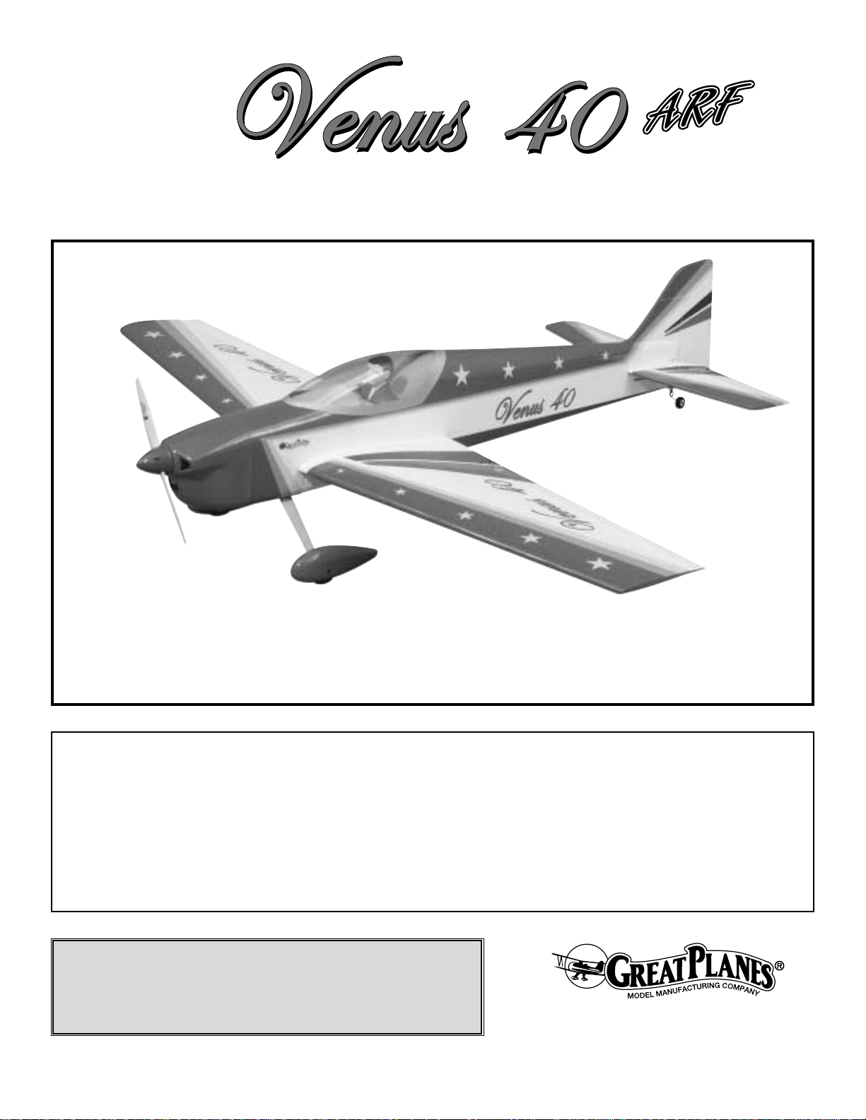
The Great Planes Venus 40 ARF is a versatile airplane
designed for pattern training and sport flying.The Venus 40
ARF is neutrally stable. That means that it will stay in
whatever position you put it in as long as it has enough
flying speed.The model exhibits no roll or pitch coupling on
knife edge when the C.G. is located at the recommended
point. On low rates, this airplane likes doing large, smooth
maneuvers, which is perfect for practicing all those
precision aerobatic maneuvers. On high rates, it hovers
great and does torque rolls with a .70 4-stroke.All in all, this
airplane is a low cost approach to pattern aerobatics that
will give you many hours of fun.
For the latest technical updates or manual corrections to the
Great Planes Venus 40 ARF visit the web site listed below
and select the Great Planes Venus 40 ARF. If there is new
technical information or changes to this model a “tech
notice” box will appear in the upper left corner of the page.
http://www.greatplanes.com/airplanes/index.html
1. Your Great Planes Venus 40 ARF should not be
considered a toy, but rather a sophisticated, working model
that functions very much like a full-size airplane.Because of
its performance capabilities, the Venus 40 ARF, if not
assembled and operated correctly, could possibly cause
injury to you or spectators and damage to property.
2. You must assemble the model according to the
instructions. Do not alter or modify the model, as doing so
may result in an unsafe or unflyable model. In a few cases
the instructions may differ slightly from the photos.In those
instances the written instructions should be considered as
correct.
3.You must take time to build straight, true and strong.
4. You must use an R/C radio system that is in first-class
condition, and a correctly sized engine and components
(fuel tank, wheels, etc.) throughout the building process.
5.You must correctly install all R/C and other components
so that the model operates correctly on the ground and in
the air.
6.You must check the operation of the model before every
flight to insure that all equipment is operating and that the
model has remained structurally sound. Be sure to check
clevises or other connectors often and replace them if they
show any signs of wear or fatigue.
7. If you are not already an experienced R/C pilot, you
should fly the model only with the help of a competent,
experienced R/C pilot.
8.While this kit has been flight tested to exceed normal use,
if the plane will be used for extremely high stress flying,
such as extreme 3D flying, the modeler is responsible for
taking steps to reinforce the high stress points.
PRO TECT YOUR MODEL,Y OURSELF
& OTHERS...FOLLOW THESE
IMPORTANT SAFETY
PRECAUTIONS
INTRODUCTION
TABLE OF CONTENTS
2
Page 3
9. Remove the identification tag from the decal sheet, fill it
out and place it on or inside the model.
Remember: Take your time and follow the instructions
to end up with a well-built model that is straight
and true.
If you have not flown this type of model before, we
recommend that you get the assistance of an experienced
pilot in your R/C club for your first flights. If you’re not a
member of a club, your local hobby shop has information
about clubs in your area whose membership includes
experienced pilots.
In addition to joining an R/C club, we strongly recommend
you join the AMA (Academy of Model Aeronautics). AMA
membership is required to fly at AMA sanctioned clubs.
There are over 2,500 AMA chartered clubs across the
country .Among other benefits, the AMA provides insurance
to its members who fly at sanctioned sites and events.
Additionally, training programs and instructors are available
at AMA club sites to help you get started the right way.
Contact the AMA at the address or toll-free telephone
number below:
Academy of Model Aeronautics
5151 East Memorial Drive
Muncie, IN 47302-9252
Tele. (800) 435-9262
Fax (765) 741-0057
Or via the Internet at: http://www.modelaircraft.org
This is the list of hardware and accessories required to
finish the Venus 40 ARF. Order numbers are provided in
parentheses.
❏ 1/2 oz. Thin Pro
™
CA (GPMR6001)
❏ .40 to .51 2-Stroke or .52 to .70 4-stroke engine
❏ Suitable propellers
(refer to the engine manufacturer’s
recommendations)
❏ 3' Medium fuel tubing (GPMQ4131)
❏ Switch and charge jack mounting set (GPMM1000)
❏ Williams Brothers 1/5 scale standard pilot
(WBRQ2477)
❏ R/C f oam rubber (1/4"-HCAQ1000, or 1/2" HCA Q1050)
❏ Great Planes Aluminum Fuel Line Plug (GPMQ4166)
If you plan to use a non-computer radio you will also need:
❏ 4-channel radio with five servos (two aileron servos)
❏ Y-harness for dual aileron servos (HCAM2500 for
Futaba®J)
If you plan to use a computer radio you will also need:
❏ 5-channel radio with five servos (two aileron servos)
❏ (2) 6" Servo extension cords (HCAM2000 for Futaba
J)
In addition to common household tools and hobby tools, this
is the “short list” of the most important items required to
build the Venus 40 ARF.
Great Planes Pro™CA and Epoxy
glues are recommended.
❏ Top Flite
®
MonoKote®sealing iron (TOPR2100)
❏ Top Flite Panel Line Pen (TOPQ2510)
❏ 1/2 oz. Thin Pro CA (GPMR6001)
❏ 1/2 oz. Medium Pro CA+ (GPMR6007)
❏ 30-Minute Epoxy (GPMR6047)
❏ Pacer Canopy Glue Formula 560 (PAAR3300)
❏ Hobby knife (HCAR0105)
❏ #11 blades (HCAR0211)
❏ Small T-pins (HCAR5100)
❏ Builder’s triangle (HCAR0480)
❏ Electric drill and 1/16" [1.6mm], 3/32" [2.4mm], 7/64"
[2.8 mm], 5/32" [4 mm] drill bits.
❏ Small phillips and flat blade screwdrivers
❏ Pliers with a wire cutter (HCAR0630)
❏ 6-32 Tap and drill set (GPMR8102)
❏ Great Planes Pro Thread Locking Compound
(GPMR6060)
❏ Heat shrink tubing (GPMM1060)
❏ Curved-tip Canopy Scissors (for trimming plastic
parts, HCAR0667)
Here is a list of optional tools mentioned in the manual that
will help you build the Great Planes Venus 40 ARF.
❏ Easy Fueler
™
fuel filling valve for glow fuel
(GPMQ4160)
❏Top Flite MonoKote heat gun (TOPR2000)
❏ Great Planes CG Machine
™
(GPMR2400)
❏Top Flite Precision Magnetic Prop Balancer
™
(TOPQ5700)
❏Top Flite Hot Sock
™
iron cover (TOPR2175)
❏ Hobbico Hot Knife
™
(HACR0770)
❏ Straightedge with scale (HCAR0475)
Optional Supplies & Tools
Adhesives & Building Supplies
Hardware & Accessories
ADDITIONAL ITEMS REQUIRED
We, as the kit manuf acturer , pro vide you with a top quality
kit and instructions, but ultimately the quality and flyability
of your finished model depends on how you build it;
therefore, we cannot in any way guarantee the
performance of your completed model, and no
representations are expressed or
implied as to the
performance or safety of your completed
model.
3
Page 4
❏ Cutting mat (HCAR0456)
❏ CA Debonder (GPMR6039)
❏ CA Applicator tips (HCAR3780)
❏ CA accelerator (GPMR6034)
❏ 6-Minute epoxy (GPMR6045)
❏ Epoxy brushes (GPMR8060)
❏ Mixing sticks (GPMR8055)
❏ Denatured alcohol (for epoxy clean up)
❏ Non-elastic monofilament or Kevlar
®
fishing line (for
stab alignment)
❏ Rotary tool such as a Dremel
®
Multi-Tool™(for
fiberglass cowl)
❏ Dead Center
™
Engine Mount Hole Locator
(GPMR8130)
❏Great Planes AccuThrow
™
Deflection Gauge (for
measuring
control throws, GPMR2405)
❏ Hobbico Servo Horn Drill (HCAR0698)
❏ Great Planes Plan Protector (GPMR6167)
❏ Great Planes Groove Tube
™
(GPMR8140)
❏ Robart Superstand II (ROBP1402)
❏ Paper towels
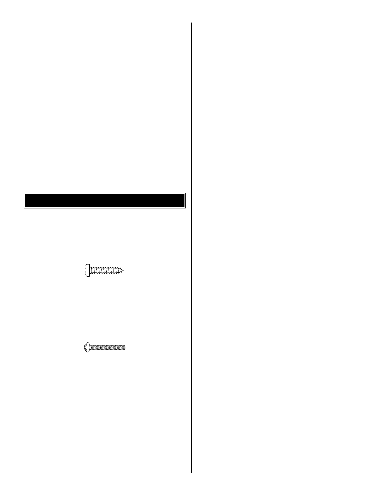
• There are two types of screws used in this kit:
Sheet metal screws are designated by a number and a
length. For example #6 x 3/4" [19mm].
This is a number six (6) screw that is 3/4" [19mm] long.
Machine screws are designated by a number, threads per
inch, and a length.For example 4-40 x 3/4" [19mm].SHCS
is just an abbreviation for “socket head cap screw” which is
a machine screw with a socket head.
This is a number four (4) screw that is 3/4" [19mm] long
with forty (40) threads per inch.
• When you see the term
test fit
in the instructions, it means
that you should first position the part on the assembly
without using any glue, then slightly modify or
custom fit
the part as necessar y for the best fit.
• Whenever the term
glue
is written you should rely upon
your experience to decide what type of glue to use.When a
specific type of adhesive works best for that step, the
instructions will make a recommendation.
• Whenever just
epoxy
is specified you may use
either
30-minute (or45-minute) epoxy or6-minute epoxy. When
30-minute epoxy is specified it is highly recommended that
you use only 30-minute (or 45-minute) epoxy, because you
will need the working time and/or the additional strength.
• Photos and sketches are placed before the step they
refer to. Frequently you can study photos in following steps
to get another view of the same parts.
• The Great Planes Venus 40 ARF is factory-covered with
Top Flite
®
MonoKote®film. Should repairs ever be required,
MonoKote can be patched with additional MonoKote
purchased separately. MonoKote is packaged in six-foot
rolls, but some hobby shops also sell it by the foot.If only a
small piece of MonoKote is needed for a minor patch,
perhaps a fellow modeler would give you some. MonoKote
is applied with a model airplane covering iron, but in an
emergency a regular iron could be used. A roll of MonoKote
includes full instructions for application. Following are the
colors used on this model and order numbers for six foot
rolls.
Tr ue Red – TOPQ0227
Jet White – TOPQ0204
Cub Yellow – TOPQ0220
Teal – TOPQ0223
Royal Blue – TOPQ0221
Circus Pink – TOPQ0215
Metallic Plum – TOPQ0403
Orange – TOPQ0202
Dove Gray – TOPQ0211
IMPORTANT BUILDING NOTES
4
Page 5
5
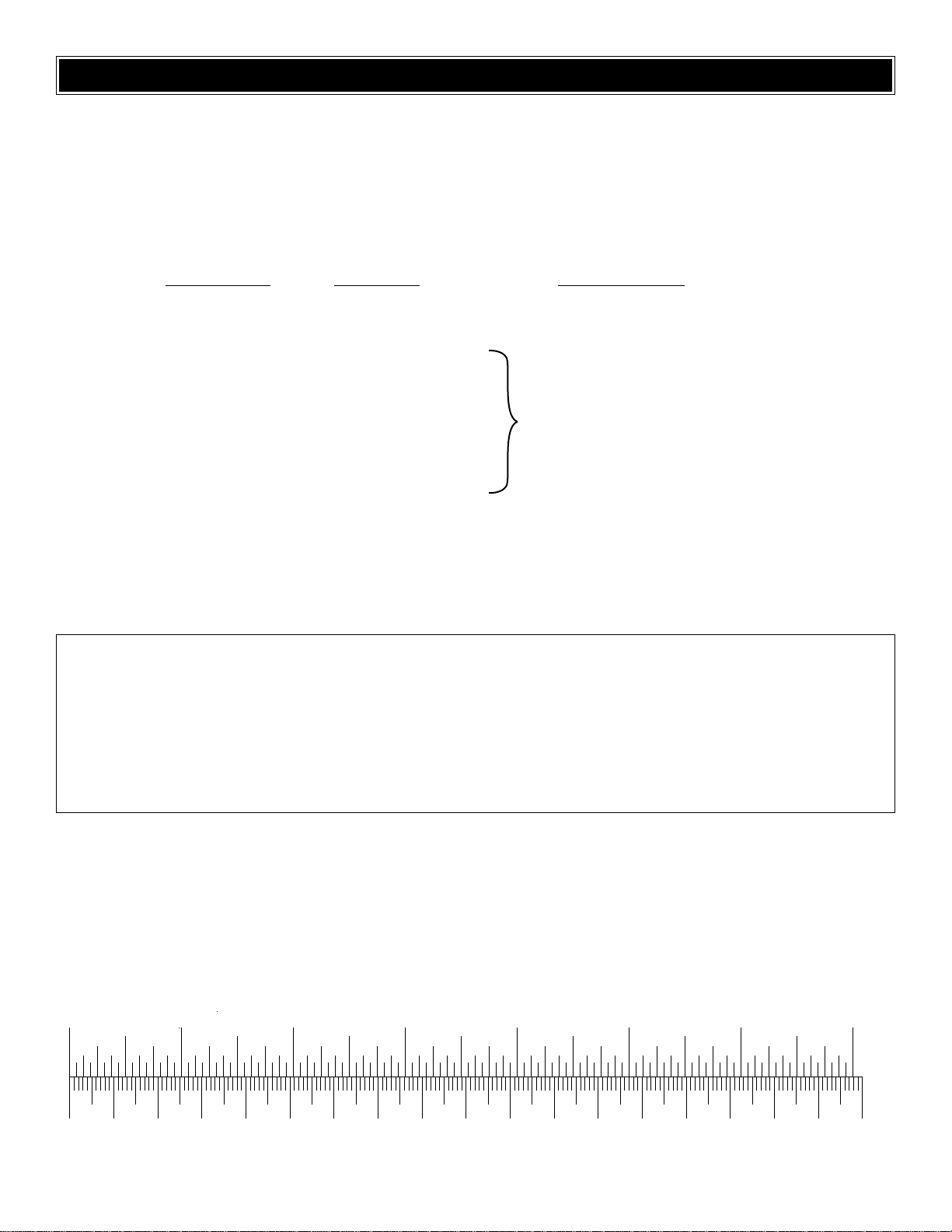
0" 1" 2" 3" 4" 5" 6" 7"
0 10 20 30 40 50 60 70 80 90 100 110 120 130 140 150 160 170 180
Inch Scale
Metric Scale
ORDERING REPLACEMENT PARTS
To order replacement parts for the Great Planes Venus 40 ARF, use the order numbers in the Replacement Parts List that
follows. Replacement parts are available only as listed. Not all parts are available separately (an aileron cannot be
purchased separately, but is only available with the wing kit). Replacement parts are not available from Product Support,
but can be purchased from hobby shops or mail order/Internet order firms. Hardware items (screws, nuts, bolts)
are also
available from these outlets .If you need assistance locating a dealer to purchase parts, visit
www.greatplanes.com and click
on “Where to Buy.” If this kit is missing parts, contact Great Planes Product Support.
Replacement Parts List
Order Number Description Ho
w to Purchase
Missing pieces............................Contact Product Suppor t
Instruction manual......................Contact Product Support
Full-size plans............................Not available
GPMA2270 ........................Wing Set
GPMA2271 ........................Fuse Set
GPMA2272 ........................Tail Set
GPMA2274 ........................Cowl
GPMA2275 ........................Canopy
GPMA2273 ........................Landing Gear
GPMA2276 ........................Wheel Pants
GPMA2277 ........................Decal Sheet
1/64" = .4 mm
1/32" = .8 mm
1/16" = 1.6 mm
3/32" = 2.4 mm
1/8" = 3.2 mm
5/32" = 4.0 mm
3/16" = 4.8 mm
1/4" = 6.4 mm
3/8" = 9.5 mm
1/2" = 12.7 mm
5/8" = 15.9 mm
3/4" = 19.0 mm
1" = 25.4 mm
2" = 50.8 mm
3" = 76.2 mm
6" = 152.4 mm
12" = 304.8 mm
18" = 457.2 mm
21" = 533.4 mm
24" = 609.6 mm
30" = 762.0 mm
36" = 914.4 mm
Metric Conversions
Contact Your Hobby
Supplier To Purchase
These Items
Page 6

6
KIT CONTENTS
1 Stab
2 Elevators
3 Fuselage & Belly Pan
4 Canopy
5 Fin
6 Rudder
7 Ailerons
8 Wing Panels
9 CA Hinge Material
10 Engine Mount
11 Dihedral Brace
12 Hardware Bag
13 Wing Bolt Plate
14 Wing Dowels
15 Tail Wheel Components
16 Servo Tray
17 Fiberglass Cowl
18 Fuel Tank
19 Wheel Pants
20 Foam Wheels
21 Aluminum Landing Gear
(5) Large Control Horns
(3) 2-56 x 36" Threaded On One End Pushrods
(1) 2-56 x 17-1/2" Threaded On One End
Pushrod
(2) 2-56 x 12" Threaded On One End Pushrods
(6) 2-56" Nylon Clevises
(6) Silicone Retainers
(4) FasLinks
(1) Brass EZ Connector
(1) 4-40 x 1/4" Socket Head Cap Screw
(1) Nylon EZ Retainer
(2) 5/32" Wheel Collars
(2) 6-32 x 1/4" Socket Head Cap Screws
(2) 1/4-20 x 2" Nylon Bolts
(10) 2-56 x 5/8" Bolts
(10) #6 Flat Washers
(10) 6-32 x 3/4" Socket Head Cap Screws
(4) 6-32 Blind Nuts
(10) #6 Lock Washers
(2) #4 x 1/2" Screws
(4) #2 x 3/8" Screws
(4) #2 Flat Washers
(2) 8-32 x 1-1/4" Socket Head Cap Screws
(4) 8-32 Hex Nuts
(2) 3/16" Wheel Collars
(2) #8 Flat Washers
(1) 11-3/4" Plastic Outer Pushrod
1
5
3
4
7
7
8
8
6
9
Kit Contents (Photographed)
Kit Contents (Not Photographed)
2
10
1216
14
15
17
18
20
19
21
11
13
Page 7
❏ 1. If you have not done so already, remove the major
parts of the kit from the box (wings, fuselage, cowl, tail
parts, etc.) and inspect them for damage. If any parts are
damaged or missing, contact Product Support at the
address or telephone number listed in the front cover.
❏ 2. Remove the masking tape and separate the ailerons
from the wing, the elevators from the stab, and the rudder
from the fin. Use a covering iron with a covering sock on
high heat to tighten the model’s covering if necessary .Apply
pressure over sheeted areas to thoroughly bond the
covering to the wood.
❏ 1. The first steps in the construction of this wing will be
the installation of the ailerons and the aileron servos. The
process described here will explain how to install the right
aileron and the right aileron servo. The process has to be
repeated again to install the left aileron and the left aileron
servo, or you can work on both at the same time.
❏ ❏ 2. Locate the pre-cut hinge slots on the wing’s trailing
edge and the leading edge of the aileron. Drill a 3/32"
[2.4mm] hole, 1/2" [12mm] deep in the center of each hinge
slot to allow the CA to “wick” in. Follow-up with a #11 blade
to clean-out the slots. Hint: If you have one, use a high-
speed
rotary tool to drill the holes.
❏ ❏ 3. Use a sharp #11 blade to cut a strip of covering
from the hinge slots in the wing and aileron.
❏ ❏ 4. Cut four 3/4" x 1" [19mm x 25mm] hinges from the
CA hinge strip. Snip off the corners so they go in easier.
❏ ❏ 5. Test fit the ailerons to the wing with the hinges. If
the hinges do not remain centered, stick a pin through the
middle of the hinge to hold it in position.
❏ ❏ 6. Remove any pins you may have inserted into the
hinges. Adjust the aileron so that there is a small gap
between the LE of the aileron and the wing.The gap should
be small–just enough to see light through or to slip a piece
of paper through.
❏ ❏ 7. Apply six drops of thin CA to the top and bottom of
each hinge. Do not use CA accelerator. After the CA has
fully hardened, test the hinges by pulling on the aileron.
TEMPORARY PIN
TO KEEP HINGE
CENTERED
1"
[25mm]
1"
[25mm]
3/4"
[19mm]
DRILL A 3/32" HOLE
1/2" DEEP, IN CENTER
OF HINGE SLOT
Attach the Ailerons
ASSEMBLE THE WING
PREPARATIONS
7
Page 8
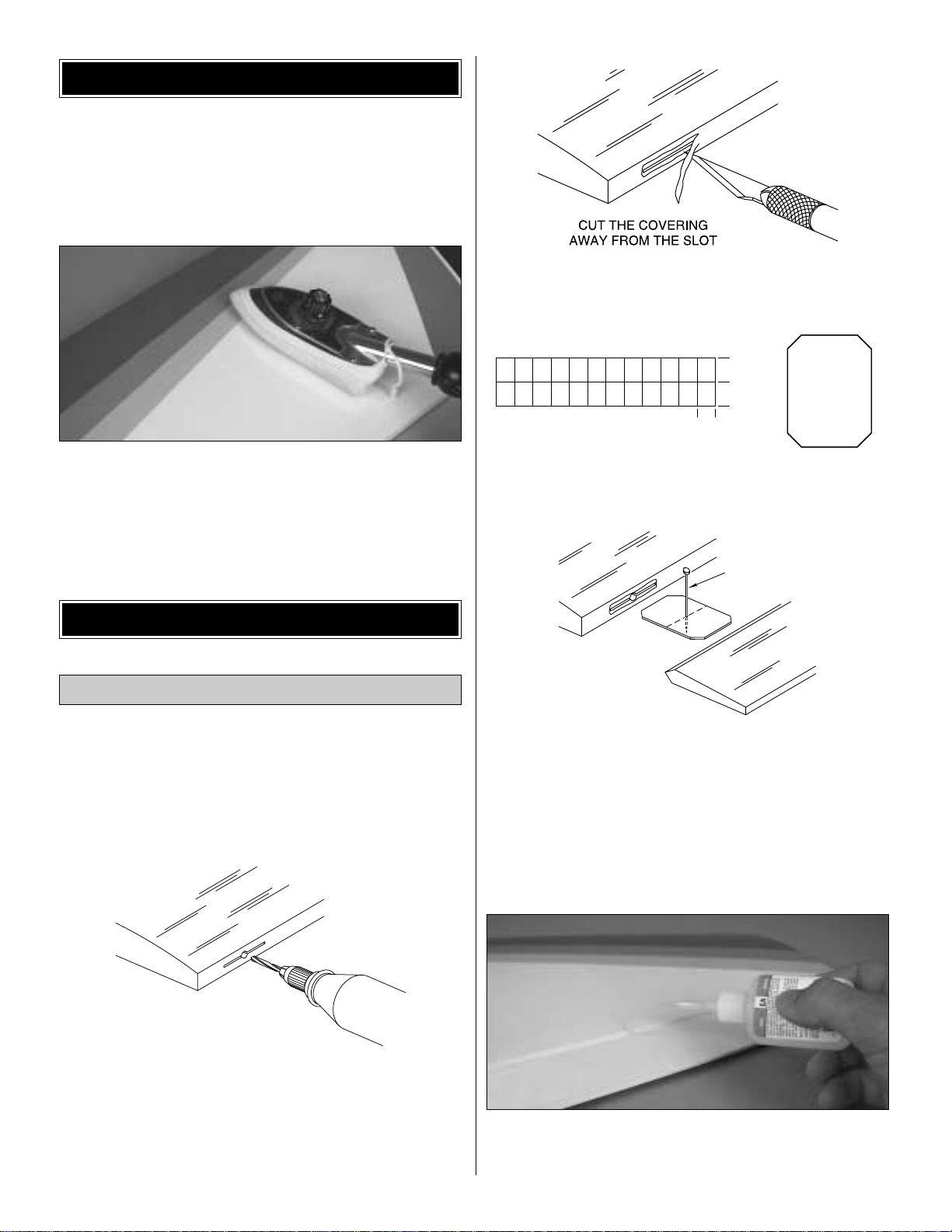
❏ ❏ 8. Feel through the MonoKote on the bottom surface
of the wing and find the opening for the aileron servo. Cut
the covering 1/8" [3.2mm] inside the opening.Use a sealing
iron or trim seal tool to seal the covering to the edges of the
opening.
❏ ❏ 9. Feel through the MonoKote on the top surface of
the wing and find the hole for the servo lead. Cut the
covering at the edges of the hole and use a sealing iron to
seal the MonoKote to the wing’s structure.
❏ ❏ 10. Tie the string inside the aileron servo opening to
the aileron servo lead. Pull the servo lead out of the end of
the wing with the string, then pull the lead through the servo
lead’s hole in the top of the wing. Test fit the servo in the
opening and trim the opening if necessary.Mark the location
of the servo mounting screws and drill 1/16" [1.6mm] holes
at the marks.Wick some thin CA in the holes you just made
and install the aileron servo with the hardware that was
supplied with it.
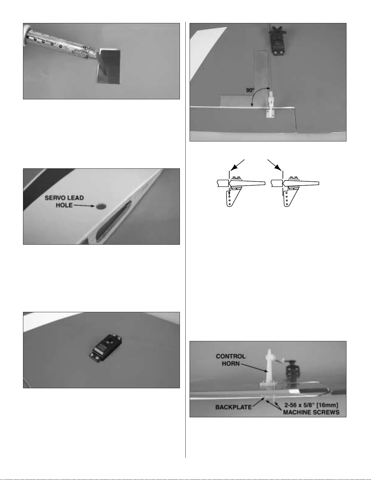
❏ ❏ 11. Thread a nylon clevis to one of the 12" [305mm]
threaded on one end pushrods approximately 18 full turns.
Connect the clevis to a large nylon control horn and slip a
silicone retainer onto it. Align the pushrod 90 degrees to the
aileron’s edge as shown above and mark the control horn
screw mounting holes on the aileron. Position the control
horn on the aileron as shown in the above line drawing.
❏ ❏ 12. Use a 1/16" [1.6mm] drill bit to drill the control
horn’s screw holes. Wick some thin CA into the holes and
mount the control horn using two 2-56 x 5/8mm" [16mm]
machine screws and the control horn’s back plate.You may
cut away any excess threads.
INCORRECTCORRECT
HINGE LINE
8
Page 9
❏ ❏ 13. Cut up a ser vo arm as shown above, attach it to
the servo and center it so that the servo arm is 90 degrees
to the pushrod. Center the aileron and mark on the pushrod
where it meets with the servo arm’s hole. Enlarge the hole
on the servo arm with a Hobbico Servo Horn Drill (or a #48
or 5/64" [2mm] drill bit). Bend the pushrod 90 degrees up
and install a FasLink as shown in the sketch above. Cut
away any excess wire, leaving 1/16" [1.6mm] protruding
from the FasLink.
❏ 14. If you have not done so, go back to step 1 and finish
the left wing the same way.
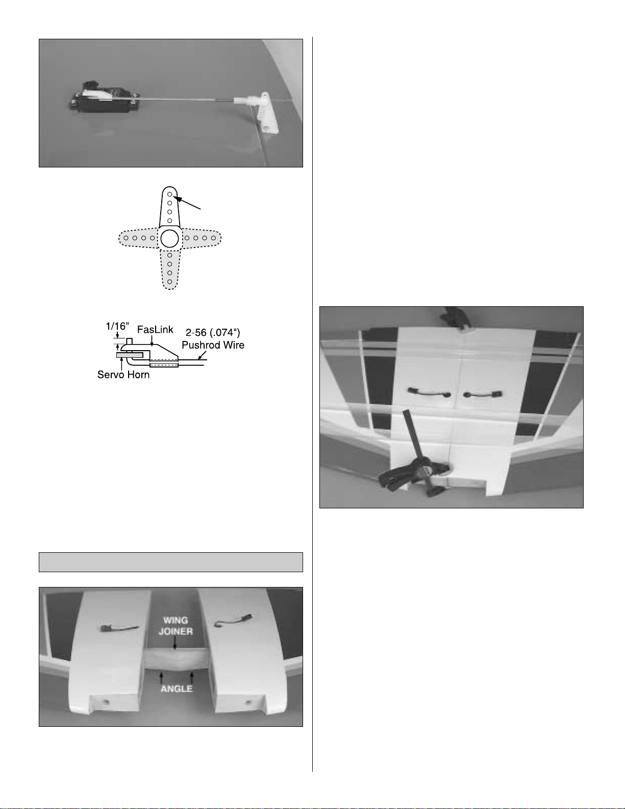
❏ 1. Tape the ser vo leads to the top of the wing to keep
them out of the way when joining the wing panels.Test fit the
wing halves with the hardwood joiner. Be certain that the
dihedral angle on the wing joiner is pointing towards the
bottom of the wing.You may need to sand the joiner slightly
to obtain a perfect fit.
❏ 2. The following are critical steps in the construction of
your model.You want to make sure you take as much time
as necessary to glue the two wings together correctly .Epoxy
should be used generously in each one of the following
steps. Use 30-minute epoxy to allow enough time to fit the
parts and to wipe off the excess glue with denatured alcohol
and a paper towel.
❏ 3.Prepare 3/4 oz [22cc] of 30-minute epoxy. Apply epoxy
to the right wing’s wing joiner pocket and to the right side of
the wing joiner.Insert the wing joiner into the pocket. Apply
epoxy to the other half of the wing joiner , the left wing’s wing
joiner pocket and both root ribs. Hold both wings together
tightly. Clean up any excess epoxy that squeezes out. Use
masking tape to hold both wings together until the epoxy
has cured. Again, wipe off any excess epoxy with alcohol
and a paper towel. Set the wing aside and do not disturb
until the epoxy has cured.
Note: If the panels are joined correctly and the fit is tight,
you should obtain the correct dihedral. If you would like to
check it, set the bottom of one wing flat against your
working surface.The bottom of the other wing tip should be
raised 2-3/16" [55.5mm] from your working surface.
Join the Wing
CUT OFF
9
UNUSED ARMS
ENLARGE TO
5/64"
Page 10

❏ 4. Find the two 1-1/4" x 1/4" [30mm x 6.4mm] hardwood
wing dowels and make a mark on the dowels 1/4" [6.4mm]
from the end of each as shown above. Sand the cor ners of
the ends slightly. Mix a small amount of epoxy and drop it
into the wing’s dowel holes. Also apply some epoxy on the
dowels. Insert the dowels up to the mark you just made, so
that just 1/4" [6.4mm] of each dowel protrudes.Clean up any
excess epoxy.
❏ 1. Inspect the blind nuts that are pressed into the wing
bolt plate in the fuselage.Apply a little epoxy around them
on
the inside of the plate to prevent them from becoming loose .
Do not get epoxy in the blind nuts.
❏ 2. Feel through the MonoKote at the trailing edge of the
wing for the pre-drilled wing bolt holes. Cut away the
MonoKote on the top and bottom of the wing and seal with
a sealing iron.
❏ 3.Test fit the wing to the fuse and bolt it in position using
two 1/4-20 x 2" [51mm] nylon bolts.If necessary, enlarge or
adjust the wing bolt holes in the wing so the wing bolts will
align with the blind nuts.
❏ 4. Unscrew the wing bolts about 1/2" [12mm]. Place a
ruler against the bolts as shown and with a Top Flite Panel
Line Pen, mark a line along the edge of the ruler. Remove
the wing bolts.
❏ 5. Find the 1/8" x 1-1/4" x 2-7/8" [3.2mm x 32mm x
73mm] wing bolt plate. Draw two centerlines on the wing
bolt plate.Line up the centerlines on the wing bolt plate with
the bolt line you previously drew and the centerline of the
wing. Mark the edges of the wing bolt plate on the wing.
Remove the wing from the plane.
❏ 6.Cut the MonoKote 1/16" [1.6mm] inside of the lines you
just made. Use a sharp #11 hobby knife or use the
Expert
Mount the Wing on the Fuselage
10
Page 11

Tip
that follows to cut the covering from the wing. Use care
to cut only into the covering and not into the wood.
❏ 7.Glue the wing bolt plate in place with epoxy. Clamp the
plate in place so that it does not move while the epoxy
cures. Clean off any excess epoxy with a paper towel and
alcohol and let cure.
❏ 8. Flip the wing over.Use a 1/4" [6.4mm] drill bit through
the pre-drilled wing bolt holes to drill through the wing bolt
plate as shown. Hint: If you clamp a 1/4" [6.4mm] piece of
wood (not included) to the bottom of the wing right under the
wing bolt plate the wood will not splinter. Use thin CA to
strengthen the hole.
❏ 9. Install the wing on the fuselage using two 1/4-20 x 2"
[51mm] nylon bolts.Find the belly pan and feel through the
MonoKote for the two wing bolt holes. Cut away the
MonoKote and seal the edges with a sealing iron. Fit the
belly pan under the wing and mark its edges on the wing
with a Top Flite Panel Line Pen. Hint: If you tape the belly
pan to the fuselage for this step it will not mov e and it will be
easier to mark both sides of the belly pan on the wing.
❏ 10. Remove the belly pan and use a hobby knife with a
sharp #11 blade or follow the previous
Expert Tip
to cut the
covering 1/16" [1.6mm] inside the lines you just marked.Be
careful not to cut the wood under the covering. Make an
additional cut 1/2" [12mm] inside the cuts already made.
Peel the covering from the wing to expose the balsa wing
sheeting. If necessar y, seal the edges with a sealing iron.
Use a soldering iron to cut the covering from the wing.
The tip of the soldering iron doesn’t have to be sharp, but
a fine tip does work best. Allow the iron to heat fully.Use
a straightedge to guide the soldering iron at a rate that
will just melt the covering and not burn into the wood.The
hotter the soldering iron, the faster it must travel to melt a
fine cut. Peel off the covering.
HOW TO CUT COVERING FROM BALSA
11
Page 12

❏ 11. Use a hobby knife with a sharp #11 blade to trim the
covering on the belly pan 1/16" [1.6mm] away from the
edge. Seal the MonoKote down with a sealing iron.
❏ 12. Use 30-minute epoxy to glue the belly pan to the
wing. Make sure the belly pan is aligned with the fuselage.
Use weights and/or tape to hold the belly pan in place.If you
are afraid of gluing the belly pan to the fuselage, you can
use some Plan Protector film or wax paper between the
fuselage and the wing. Wipe off any excess epoxy using a
paper towel and alcohol. Remove the weights once the
epoxy has cured.
❏ 13. This completes your wing.
❏ 1. Cut the covering from the slots in the fuse for the stab
and for the pushrod guide tubes.There should be two guide
tubes for the elevator and one for the rudder. Hint: Cut the
covering from the slots for the stab and fin 3/32" [2.4mm]
from both edges, thus leaving flaps of covering that can be
ironed to the stab and fin after gluing them into position.
❏ 2. Fit the stab into the fuse. Center the trailing edge by
taking accurate measurements as shown in “X”=“X” in the
photo.Once the trailing edge of the stab is centered, stick a
pin through the fin slot into the stab’s trailing edge to keep it
in position.
❏ 3. Bolt the wing to the fuse. Place the model in a building
stand. Stand five to ten feet behind the model and view the
stab and the wing. The stab and the wing should line up. If
they do not line up, place a weight on the “high” side of the
stab to bring it into alignment. If much weight is required,
remove the stab and sand the “high” side of the slot in the
fuse where the stab fits until the stab aligns with the wing.
❏ 4. Stick a pin into the center of the fuselage on top of the
firewall. Tie a small loop on one end of a 42" [1066mm]
piece of non-elastic string such as a K & S #801 Kevlar
thread (K+SR4575).Slip the loop in the string over the T-pin.
Install the Tail Surfaces
ASSEMBLE THE FUSELAGE
12
Page 13

❏ 5.Fold a piece of masking tape ov er the end of the string
and draw an arrow on it.Slide the tape along the string and
align the arrow with one corner of the stab as shown in the
photo. Swing the string over to the same position on the
other corner of the stab. Rotate the stab and slide the tape
along the string until the arrow aligns with both sides. Be
certain the stab remains centered from side-to-side during
this process.
❏ 6. Use a Top Flite Panel Line Pen to mark the outline of
the fuse onto the top and bottom of the stab.
❏ 7. Remove the stab from the fuse. Use a sharp #11
hobby knife or use the
Expert Tip on page 11
to cut the
covering 1/16" [1.6mm] inside of the lines you marked.Use
care to cut only into the covering and not into the wood.
❏ 8.Use 30-minute epoxy to glue the stab into the fuse.For
the most strength, apply epoxy to both sides of the stab and
inside the fuse where the stab fits. Slide the stab into
position. Wipe away residual epoxy with a paper towel and
alcohol. Use the pin and string method to confirm the stab
is aligned. Stand behind the model to check the stab’s
alignment with the wing. If you cut the covering as
suggested over the slots in the fuse for the stab, carefully
use a trim iron to iron the covering to the stab before the
epoxy hardens.Do not disturb the model until the epoxy has
fully hardened.
❏ 9. Fit the fin into the fuse. Mar k the outline of the fuse
onto the fin with a Top Flite Panel Line Pen. Just as you did
with the stab, remov e the covering 1/16" [1.6mm] away from
the line. Glue the fin into position with 30-minute epoxy
using a builder’s square to make certain the fin is vertical. If
necessary, pull the fin to one side or the other with masking
tape until the fin is perpendicular to the stab.
❏ 10. Inser t the tail wheel wire in the tail wheel support.
Mark the tail wheel wire 1-1/4" [32mm] from the end. Bend
the wire 90 degrees as shown above. Note: Make sure the
bent wire is in line with the tail wheel.
13
Page 14

❏ 11. Position the tail wheel assembly in place and mark
the location of the two mounting holes. Drill the two holes
with a 1/16" [1.6mm] drill bit.Wick some thin CA in the holes.
Install the tail wheel assembly using two #4 x 1/2" [12mm]
screws as shown.
❏ 12. Position the rudder in place and mar k where the tail
wire is inserted in the rudder. The bottom of the tail wheel
wire’s first coil should be 1/8" [3.2mm] away from the tail
wheel support as shown above.Use a 3/32" [2.4mm] drill bit
to drill a hole into the rudder 1-1/4" [32mm] at the mark.
Make sure the hole is perpendicular with the rudder’s
leading edge and be careful not to drill through the covering.
❏ 13. Use a Groove Tube or a sharpened 3/32" [2.4mm]
brass tube to cut a groove on the leading edge of the rudder
to accommodate the tail wheel wire.
❏ 14. Cut six CA hinges for the elevators and three for the
rudder just as it was done for the ailerons.
❏ 15. Test fit the rudder on the fin with the tail wheel wire
and the CA hinges. Adjust the groove and the hole on the
leading edge of the rudder until everything fits well.Remove
the rudder from the fin. Mix a small amount of 30-minute
epoxy and wick it into the rudder’s tail wheel wire hole.
Install the rudder in position with the CA hinges just as it
was done for the ailerons on page 7, and apply six drops of
thin CA to each side of each CA hinge.Clean up any excess
epoxy with a paper towel and alcohol.
❏ 16. Follow steps two to seven of
“Assemble the Wing”
on page 7 to install the CA hinges on the elevator.
Important:
Make sure you apply six drops of thin CA on each side of
each hinge.
14
Page 15

This airplane can use a wide variety of engines. This
installation will show the installation of an O.S.®.46 FX.The
procedure for installing other engines will be similar except
for minor variations.The engine can be installed at different
angles. On the instruction’s model the engine was installed
inverted because that is the position that requires the least
cutting of the cowl.
Note: If you use a short engine such as the O.S. .40 L.A.,
you will need to use the engine spacing template on the
back cover page to cut two 1/4" [6.4mm] plywood spacers
to be glued on the firewall.You will also need to substitute
6-32 x 1-1/4" [32mm] SHCS for the 6-32 x 3/4" [19mm]
SHCS
included with this kit.
❏ 1. Cut the engine mount template from the back cover
page. Use spray adhesive or tape to temporarily attach the
template to the firewall.Align the template using the vertical
and horizontal lines of the firewall. Drill 5/32" [4mm] holes
through the firewall at the marks.
❏ 2. Install four 6-32 blind nuts into the holes on the back
of the firewall.Use a small amount of epoxy on the blind nuts
to keep them in place.Do not get epoxy in the threads.
❏ 3. Find the left and right engine mounts and cut off the
spreader bar on both of them.
❏ 4.Remove the engine mount template.Mount the engine
mount to the firewall with four 6-32 x 3/4" [19mm] SHCS,
four #6 flat washers, and four #6 lock washers into the four
6-32 blind nuts, but do not fully tighten the SHCS.Place the
engine on the mount and adjust the width of the mount to fit
the engine. Center the molded-in “tick” marks on the engine
mount with the marks on the firewall and tighten the
mounting
bolts.It would be a good idea to use some Great Planes Pro
Thread Locking Compound on the engine mount bolts.
❏ 5.Position the engine so that the face of the drive washer
is 4-15/16" [125mm] from the front of the fuse. Use a Great
Planes Dead Center Engine Mount Hole Locator or your
own method to mark the engine mount holes onto the
engine mount. Drill the engine mount at the marks with a
#36 (7/65" [2.8mm]) drill bit. Use a 6-32 tap to thread the
hole for the engine bolts.
❏ 6.Install the engine using four 6-32 x 3/4" [19mm] SHCS,
four #6 flat washers, and four #6 lock washers.
Engine Installation
15
Page 16

❏ 7.Mark the position of the throttle pushrod on the firewall.
Remove the engine from the engine mount. Drill a 5/32"
[4mm] hole through the firewall for the throttle pushrod.Find
the 11-3/4" [298mm] plastic outer pushrod.Roughen up one
of the ends of the plastic outer pushrod. Insert it into the
hole until only about 1/4" [6.4mm] of the rough end shows
outside of the firewall as shown above and glue it in place
with CA.
❏ 8. Find the fuel tank. Assemble the stopper and tubes as
shown in the photo, and then insert them into the tank. Do
not tighten the screw to expand the stopper.You will do that
in the next step.Be certain the fuel line weight (clunk) at the
end of the fuel line inside the tank does not contact the rear
of the tank.Otherwise, the line may become stuc k abov e the
fuel level and stop the fuel flo w. Remember which is the fuel
pick-up, vent and fill tubes.You can mark the tubes with a
Top Flite Panel Line Pen if you wish.
❏ 9.Install the fuel tank in the fuse.Fit the neck through the
hole in the firewall.Be certain you install the fuel tank inside
the fuselage with the vent tube pointing up and the fill tube
down.Tighten the fuel tank screw.
❏ 10. Glue a 1/2" x 1/4" [12mm x 6.4mm] balsa stick (not
included) as shown above to hold the fuel tank in place.
❏ 11. Cut the fuel line in three 6" [152mm] length sections.
Install the three sections of fuel line on the three fuel tank
tubes. Mark the fuel lines so that you know what each one
is for. Install the engine (less muffler) and connect the fuel
carburetor line to the carburetor or remote needle valv e .Use
a Great Planes Aluminum Fuel Line Plug to plug the fill fuel
line. If you wish, you could install a Great Planes Easy
Fueler™Valve for glow engines instead of the third (fill) line
in the tank.
❏ 1.Glue the 1/8" [3.2mm] servo tray in place with CA.Add
a couple of drops of CA where the plastic outer pushrods go
through the formers. Note: If your throttle pushrod is
installed on the opposite side of the fuselage from what is
shown in the images, you may want to flip the servo tray to
better align the throttle pushrod with the throttle servo.
❏ 2.Find the .074" x 17-1/2" [444mm] threaded on one end
pushrod, a clevis and a silicone retainer. Thread the clevis
Radio Installation
16
Page 17

onto the rod approximately 18 full turns, slip the silicone
retainer on the rod and install the rod in the throttle outer
pushrod. Install the engine and attach the clevis on the
engine throttle arm. Make sure you have a free moving
linkage. Slip the retainer on the clevis.
❏ 3.Locate three clevises, three retainers and three 0.074"
x 36" [914mm] threaded on one end pushrods. Thread a
clevis approximately 18 full turns onto each pushrod and
slip a silicone retainer half way onto each clevis. Insert a
pushrod into each one of the pushrod guide tubes.
❏ 4. Connect a large nylon control horn on each clevis and
position the control horn on each control surface as shown.
Drill 3/32" [2.4mm] holes through the elevators and rudder
to accommodate the control horn’s screws.Wick some thin
CA into the holes. Install the elevator and rudder control
horns with six 2-56 x 5/8" [16mm] bolts and the control horn
back plates.
❏ 5.Test fit the rudder , elev ator and throttle servos.
Depending
on the size of your servos you may have to slightly trim the
tray. Place the servos in the tray and mount them with the
hardware that came with the servos. Center the rudder
servo arm. If necessary, bend the pushrod slightly to align it
with the servo arm hole you want to use.
❏ 6. Center the r udder and make a mark on the pushrod
where it meets with the servo arm hole you want to use.
Bend the pushrod 90 degrees up and install a FasLink on
the rudder pushrod as shown in the sketch. Cut away any
excess wire, leaving 1/16" [1.6mm] above the FasLink.
❏ 7.Center the elev ator servo arm and elev ators .Align one
of the elevator pushrods with the hole y ou w ant to use in the
servo arm and mark it where it meets the hole. Slip two
5/32" [4mm] wheel collars onto the pushrod. Center the
elevator that this pushrod controls. Bend the pushrod 90
degrees up at the mark and install a FasLink. Center the
other elevator and bend its pushrod as shown above to
mate with the first pushrod. Place the two wheel collars as
shown, put a drop of Great Planes Pro Thread Locking
Compound in the wheel collar screw hole and tighten the
INCORRECTCORRECT
HINGE LINE
17
Page 18

wheel collar SHCS (6-32 x 1/4" [6.4mm]). Note: The
preceding image shows the completed pushrod assembly
outside of the radio compartment for clarity.
❏ 8. Install a screw-lock pushrod connector on the throttle
servo arm. Insert the throttle pushrod into the connector.
Use a 4-40 x 1/8" [3.2mm] socket head cap screw to secure
the pushrod into the connector. Make sure that you get the
full range of carburetor rotation with the servo rotation. Use
some Great Planes Pro Thread Locking Compound on the
SHCS to prevent it from coming loose with vibration.
❏ 9. Install a radio switch and a charge receptacle on the
fuselage’s side away from the exhaust. Wrap the battery
pack and the receiver in at least 1/4" [6.4mm] of R/C foam
rubber and install them in the fuselage.Use shrink tubing to
secure the battery and switch connections.Connect all your
servos and the “Y” harness to the receiver.Glue two 1/2" x
1/4" [12mm x 6.4mm] balsa sticks (not included) to secure
the battery and receiver in place.
❏ 10.Make a small hole through the bottom of the fuselage
and route the radio antenna to the aft fuselage.Be sure that
there is a strain relief inside the fuselage on the antenna to
keep stress off the solder joint inside the receiver. Use a
small rubber band to keep the antenna extended. Hold it
with a T-pin at the bottom of the fuselage or around the tail
wheel wire.
❏ 1.Draw a line 1/2" [12mm] away from the firew all, parallel
to the firewall.
❏ 2.Test fit the cowl on the fuselage. Push the cowl all the
way up to the line. Center the cowl ring with the engine
crankshaft. Use a rotary tool to cut cooling openings and a
carburetor opening on the fiberglass cowl. Hint: It will be
easier to line up the cowl with the engine crankshaft if you
temporarily install the spinner back plate.There should be a
3/32" [2.4mm] gap between the spinner back plate and the
cowl ring.
Installing the Cowl
18
Page 19

❏ 3.Draw a line on the co wl using a Top Flite Panel Line P en
1/4"
[6.4mm] parallel to the cowl’ s edge .Make two marks on
that line 1" [25mm] and another 3-3/4" [95mm] away from
the bottom of the firewall. Do the same for the other side of
the cowl.
❏ 4.Position the cowl on the fuselage all the way to the 1/2"
[12mm] line and center the cowl ring with the engine
crankshaft. Drill a 1/16" [1.6mm] hole through the fiberglass
cowl and fuselage as shown on each mark. Make sure you
do not drill through the fuel tank. Hint: Tape the cowl to the
fuselage so it will not move as you drill the holes.Wipe the
line off with denatured alcohol.
❏ 5. Remove the cowl.Wick some thin CA into the holes in
the fuselage.Install an extension on the carburetor’s needle
valve. Install the engine’s muffler. Use paper strips to mark
the location of the needle valve, engine glow plug access
and muffler.Remove the muffler and needle valve.
❏ 6.Install the cowl with four #2 x 3/8" [9.5mm] screws and
four #2 washers and mark the location of the needle valve,
muffler, pressure line , and engine glow plug on the co wl with
a Top Flite Panel Line Pen.Remove the cowl and use a high
speed rotary tool to cut away the holes marked. You will
need to make a cut from the center of the muffler’s slot to
the aft edge of the cowl as shown to be able to remove the
cowl from the fuselage without removing the muffler. If you
wish, you could just extend the muffler slot all the w ay to the
edge of the cowl.Once all the holes are made, carefully wick
a little CA on the edges of the cuts to stiffen the fibers up.
Then, cut them with a hobby knife or scissors.
❏ 7.Install the muffler, the cowl, the supplied 2" [51mm] red
spinner, the needle valve, and the engine’s prop.
This finishes the installation of the engine.
19
Page 20

❏ 1. Feel through the MonoKote for the two landing gear
mounting holes on the bottom side of the fuselage.Cut away
the covering over the holes and install the main landing gear
with the angle towards the back using two 6-32 x 3/4"
[19mm] SHCS, two #6 washers and two #6 lock washers.
Use some Great Planes Pro Thread Locking Compound on
the screws.
❏ 2. Install the wheels and wheel pants. Use an 8-32 x
1-1/4" [32mm] SHCS, two 8-32 hex n uts, one #8 washer and
a 3/16" [4.8mm] wheel collar for each wheel and wheel pant.
The wheel collar only works as a spacer. Check the above
image and diagram to install the wheel pants correctly. Also,
remember to line up the wheel pants with the fuselage. Use
some Great Planes Pro Thread Locking Compound on the
nuts to prevent them from loosening with vibration. Make
sure you center the wheel within the wheel pant opening.
This finishes the installation of the landing gear.
❏ 1. Cut the instr ument panel decal from the decal sheet
and place it in position in the cockpit.
❏ 2. If you wish to install a pilot, now it is the time to do it.
On the instruction manual model we used a Williams
Brothers Standard 1/5 Pilot.T rim the canopy at the cut lines .
Glue the canopy to the fuselage using Pacer Formula 560
Canopy glue. Clean up any excess glue and tape the
canopy in place until the glue is dry.
1. Use scissors or a sharp hobby knife to cut the decals
from the sheet.
2. Be certain the model is clean and free from oily
fingerprints and dust. Prepare a dishpan or small bucket
with a mixture of liquid dish soap and warm water–about
one teaspoon of soap per gallon of water. Submerse the
decal in the soap and water and peel off the paper backing.
Note: Even though the decals have a “sticky-back” and are
not the water transfer type, submersing them in soap and
water allows accurate positioning and reduces air bubbles
underneath.
Apply the Decals
Finish the Cockpit
Install the Landing Gear
20
Page 21

3. Position the decals on the model as seen on the box
cover. Holding the decal down, use a paper towel to wipe
most of the water away.
4. Use a piece of soft balsa or something similar to
squeegee remaining water from under the decal. Apply the
rest of the decals the same way.
❏ 1. Turn on the transmitter and receiver and center the
trims. If necessar y, remove the servo arms from the servos
and reposition them so they are centered. Reinstall the
screws that secure the servo arms.
❏ 2. With the transmitter and receiver still on, check all the
control surfaces to see if they are centered. If necessary,
adjust the clevises on the pushrods to center the control
surfaces.
❏ 3. Make certain that the control surfaces and the
carburetor respond in the correct direction as shown in the
diagram. If any of the controls respond in the wrong
direction, use the servo reversing in the transmitter to
reverse the servos connected to those controls. Be cer tain
the control surfaces have remained centered. Adjust if
necessary.
Use a Great Planes Accu-Throw (or a ruler) to accurately
measure and set the control throw of each control surface
as indicated in the chart that follows. If your radio does not
have dual rates, we recommend setting the throws
somewhere between the low rate and the high rate setting.
Note: The throws are measured at the widest part of the
elevators, rudder and ailerons.
IMPORTANT: The Great Planes Venus 40 ARF has been
extensively flown and tested to arrive at the throws at
which it flies best. Flying your model at these throws will
provide you with the greatest chance for successful first
flights. If, after you have become accustomed to the way
the Great Planes Venus 40 ARF flies, you would like to
change the throws to suit your taste, that is fine.However,
too much control throw could make the model difficult to
control, so remember, “more is not always better.”
These are the recommended control surface throws:
High Rate Low Rate
ELEVATOR: 7/16" [11mm] up 1/4" [6.5mm] up
9/16" [14mm] down 3/8" [9.5mm] down
RUDDER: 1-5/8" [41mm] right 1" [25m] right
1-5/8" [41mm] left 1" [25mm] left
AILERONS: 5/16" [8mm] up 3/16" [5mm] up
5/16" [8mm] down 3/16" [5mm] down
Set the Control Throws
4-CHANNEL
TRANSMITTER
4-CHANNEL
TRANSMITTER
4-CHANNEL
TRANSMITTER
4-CHANNEL RADIO SET-UP
(STANDARD MODE 2)
TRANSMITTER
4-CHANNEL
ELEVATOR MOVES UP
RIGHT AILERON MOVES UP
LEFT AILERON MOVES DOWN
RUDDER MOVES RIGHT
CARBURETOR WIDE OPEN
Check the Control Directions
GET THE MODEL READY TO FLY
21
Page 22

At this stage the model should be in ready-to-fly condition
with all of the systems in place including the engine, landing
gear, covering and paint, and the radio system.
❏ 1. Use a felt-tip pen or 1/8"-wide tape to accurately mark
the C.G.on the top of the wing on both sides of the fuselage.
The recommended C.G.is located 4-5/8" [118mm] back from
the leading edge of the wing where it meets the fuselage.
❏ 2.With the wing attached to the fuselage, all parts of the
model installed (ready to fly) and an empty fuel tank, place
the model upside-down on a Great Planes CG Machine™, or
lift it upside-down at the balance point you marked.
❏ 3. If the tail drops, the model is “tail heavy” and the
battery pack and/or receiver must be shifted forward or
weight must be added to the nose to balance. If the nose
drops, the model is “nose heavy” and the battery pack
and/or receiver must be shifted aft or weight must be added
to the tail to balance. If possible, relocate the battery pack
and receiver to minimize or eliminate any additional ballast
required. If additional weight is required, nose weight may
be easily added by using a “spinner weight”(GPMQ4645 for
the 1 oz. [28g] weight, or GPMQ4646 for the 2 oz. [56g]
weight). If spinner weight is not practical or is not enough,
use Great Planes (GPMQ4485) “stick-on” weights. A good
place to add stick-on nose weight is to the firewall (don’t
attach weight to the cowl–it is not intended to support
weight). Begin by placing incrementally increasing amounts
of weight on the bottom of the fuse over the firewall until the
model balances. Once you have determined the amount of
weight required, it can be permanently attached. If required,
tail weight may be added by cutting open the bottom of the
fuse and gluing it permanently inside.
Note: Do not rely upon the adhesive on the back of the lead
weight to permanently hold it in place. Over time, fuel and
exhaust residue may soften the adhesive and cause the
weight to fall off. Use #2 sheet metal screws, RTV silicone
or epoxy to permanently hold the weight in place.
❏ 4. IMPORTANT: If you found it necessary to add any
weight, recheck the C.G.after the weight has been installed.
❏ 1. With the wing level, have an assistant help you lift the
model by the engine propeller shaft and the bottom of the
fuse under the TE of the fin.Do this several times.
❏ 2. If one wing always drops when you lift the model, it
means that side is heavy. Balance the air plane by adding
weight to the other wing tip. An airplane that has been
laterally balanced will track better in loops and other
maneuvers.
Balance the Model Laterally
This is where your model should balance for your first
flights. Later, you may wish to experiment by shifting the
C.G. up to 5/8" [16mm] forward or 1/4" [6.5mm] back to
change the flying characteristics. Moving the C.G.
forward may improve the smoothness and stability, but it
may then require more speed for takeoff and make the
airplane more difficult to slow for landing. Moving the
C.G.aft makes the model more maneuverable, but could
also cause it to become too difficult for you to control. In
any case, start at the location we recommend and do not
at any time balance your model outside the
recommended range. At the recommended C.G. the
model has no roll coupling on knife-edge and a very small
pitch coupling.
More than any other factor, the C.G. (balance point) can
have the greatest effect on how a model flies, and may
determine whether or not your first flight will be
successful.If you value this model and wish to enjoy it for
many flights, DO NOT OVERLOOK THIS IMPORTANT
PROCEDURE. A model that is not properly balanced will
be unstable and possibly unflyable.
Balance the Model (C.G.)
22
4-5/8" [118mm]
4-5/8" [118mm]
Page 23

No matter if you fly at an AMA sanctioned R/C club site or
if you fly somewhere on your own, you should always have
your name, address, telephone number and AMA number
on or inside your model. It is required at all AMA R/C club
flying sites and AMA sanctioned flying events. Fill out the
identification tag on the decal sheet and place it on or inside
your model.
Follow the battery charging instructions that came with your
radio control system to charge the batteries. You should
always charge your transmitter and receiver batteries the
night before you go flying, and at other times as
recommended by the radio manufacturer.
Note: Checking the condition of your receiver battery pack
is highly recommended. All batter y packs, whether it’s a
trusty pack you’ve just tak en out of another model, or a ne w
battery pack you just purchased, should be cycled, noting
the discharge capacity .Oftentimes, a weak battery pack can
be identified (and a valuable model sav ed!) b y comparing its
actual capacity to its rated capacity. Refer to the instructions
and recommendations that come with your cycler. If you
don’t own a battery cycler, perhaps you can have a friend
cycle your pack and note the capacity for you.
Carefully balance your propeller and spare propellers before
you fly. An unbalanced prop can be the single most
significant cause of vibration that can damage your model.
Not only will engine mounting screws and bolts loosen,
possibly with disastrous effect, but vibration may also
damage your radio receiver and battery. Vibration can also
cause your fuel to foam, which will, in turn, cause your
engine to run hot or quit.
We use a Top Flite Precision Magnetic Prop Balancer
™
(TOPQ5700) in the workshop and keep a Great Planes
Fingertip Prop Balancer (GPMQ5000) in our flight box.
If the engine is new, follow the engine manufacturer’s
instructions to break-in the engine. After break-in,
confirm that the engine idles reliably, transitions smoothly
and rapidly to full power and maintains full
power–indefinitely.
After you run the engine on the model, inspect the model
closely to make sure all screws remained tight, the hinges
are secure, the prop is secure and all pushrods and
connectors are secure.
Ground check the operational range of your r adio before the
first flight of the day. With the transmitter antenna collapsed
and the receiver and transmitter on, you should be able to
walk at least 100 feet away from the model and still have
control. Have an assistant stand by your model and, while
you work the controls, tell you what the control surfaces are
doing. Repeat this test with the engine running at various
speeds with an assistant holding the model, using hand
signals to show you what is happening. If the control
surfaces do not respond correctly, do not fly! Find and
correct the problem first. Look for loose servo connections
or broken wires, corroded wires on old servo connectors,
poor solder joints in your battery pack or a defective cell, or
a damaged receiver crystal from a previous crash.
Keep all engine fuel in a safe place, away from high heat,
sparks or flames, as fuel is very flammable. Do not smoke
near the engine or fuel; and remember that engine exhaust
gives off a great deal of deadly carbon monoxide .Therefore,
do not run the engine in a closed room or garage.
Get help from an experienced pilot when learning to
operate engines.
Use safety glasses when starting or running engines.
Do not run the engine in an area of loose gravel or sand;the
propeller may throw such material in your face or eyes.
Keep your face and body as well as all spectators away
from the plane of rotation of the propeller as you start and
run the engine.
Keep these items away from the prop: loose clothing, shir t
sleeves, ties, scarves, long hair or loose objects such as
pencils or screwdrivers that may fall out of shirt or jacket
pockets into the prop.
Failure to follow these safety precautions may result
in severe injury to yourself and others.
ENGINE SAFETY PRECAUTIONS
Range Check
Ground Check
Balance the Propeller
Charge the Batteries
Identify Y our Model
PREFLIGHT
23
Page 24

Use a “chicken stick” or electric starter to star t the engine.
Do not use your fingers to flip the propeller. Make cer tain
the glow plug clip or connector is secure so that it will not
pop off or otherwise get into the running propeller.
Make all engine adjustments from behind the rotating
propeller.
The engine gets hot! Do not touch it during or right after
operation.Make sure fuel lines are in good condition so fuel
will not leak onto a hot engine, causing a fire.
To stop a glow engine, cut off the fuel supply by closing off
the fuel line or following the engine manufacturer’s
recommendations. Do not use hands, fingers or any other
body part to try to stop the engine. To stop a gasoline
powered engine an on/off switch should be connected to
the engine coil.Do not throw anything into the propeller of a
running engine.
Read and abide by the following Academy of Model
Aeronautics Official Safety Code:
GENERAL
1. I will not fly my model aircraft in sanctioned events, air
shows, or model flying demonstrations until it has been
proven to be airworthy by having been previously
successfully flight tested.
2. I will not fly my model aircraft higher than approximately
400 feet within 3 miles of an airport without notifying the
airport operator.I will give right of way to, and avoid flying in
the proximity of full-scale aircraft. Where necessary an
observer shall be used to supervise flying to avoid having
models fly in the proximity of full-scale aircraft.
3.Where established, I will abide by the safety rules for the
flying site I use, and I will not willfully and deliberately fly my
models in a careless, reckless and/or dangerous manner.
7. I will not fly my model unless it is identified with my name
and address or AMA number, on or in the model.
9. I will not operate models with pyrotechnics (any device
that explodes, burns, or propels a projectile of any kind).
RADIO CONTROL
1.I will have completed a successful radio equipment
ground
check before the first flight of a new or repaired model.
2. I will not fly my model aircraft in the presence of
spectators until I become a qualified flier, unless assisted b y
an experienced helper.
3.I will perform my initial turn after takeoff away from the pit
or spectator areas, and I will not thereafter fly over pit or
spectator areas, unless beyond my control.
4. I will operate my model using only radio control
frequencies currently allowed by the F ederal
Communications
Commission.
❏ 1. Fuelproof all areas exposed to fuel or exhaust
residue such as the wing saddle area, belly pan, or
the engine spacer if needed.
❏ 2. Check the C.G. according to the measurements
provided in the manual.
❏ 3. Be certain the battery and receiver are securely
mounted in the fuse.Simply stuffing them into place
with foam rubber is not sufficient.
❏ 4. Extend your receiver antenna and make sure it has
a strain relief inside the fuselage to keep tension off
the solder joint inside the receiver.
❏ 5. Balance your model
laterally
as explained in the
instructions.
❏ 6. Use thread locking compound to secure critical
fasteners such as the screws that hold the
carburetor arm (if applicable), screw-lock pushrod
connectors, etc.
❏ 7. Add a drop or two of oil to the axles so the wheels
will turn freely.
❏ 8. Make sure all hinges are securely glued in place.
❏ 9. Reinforce holes for wood scre ws with thin CA where
appropriate (servo mounting screws, cowl mounting
screws, etc.).
❏ 10. Confirm that all controls operate in the correct
direction and the throws are set up as specified in
this manual.
❏ 11. Make sure there are silicone retainers on all the
clevises and that all servo arms are secured to the
servos with the screws included with your radio.
❏ 12. Secure the connections between servo wires and
Y-connectors or servo extensions, and the
connection
between your battery pack and the on/off switch
with vinyl tape, heat shrink tubing or special clips
suitable for that purpose.
During the last few moments of preparation your mind
may be elsewhere anticipating the excitement of the first
flight.Because of this, you may be more lik ely to o v erlook
certain checks and procedures that should be performed
before the model is flown.To help avoid this, a check list
is provided to make sure these important areas are not
overlooked. Many are covered in the instruction manual,
so where appropriate, refer to the manual for complete
instructions. Be sure to check the items off as they are
completed (that’s why it’s called a
check list!
).
CHECK LIST
AMA SAFETY CODE (excerpt)
24
Page 25

❏ 13. Make sure any servo extension cords y ou ma y ha v e
used do not interfere with other systems (servo
arms, pushrods, etc.).
❏ 14. Secure the pressure tap (if used) to the muffler with
high temp RTV silicone, thread locking compound
or J.B.Weld.
❏ 15. Make sure the fuel lines are connected and are not
kinked.
❏ 16. Balance your propeller (and spare propellers).
❏ 17. Tighten the propeller nut and spinner.
❏ 18. Place your name, address, AMA number and
telephone number on or inside your model.
❏ 19. Cycle your receiver battery pack (if necessary) and
make sure it is fully charged.
❏ 20. If you wish to photograph your model, do so before
your first flight.
❏ 21. Remember to range check your radio when you get
to the flying field.
The Great Planes Venus 40 ARF is a great-flying model that
flies smoothly and predictably. The Great Planes Venus 40
ARF does not, however, possess the self-recovery
characteristics of a primary R/C trainer and should be flown
only by experienced R/C pilots.
A fully cowled engine may run at a higher temperature than
an un-cowled engine. For this reason, the fuel mixture
should be richened so the engine runs at about 200 rpm
below peak speed. By r unning the engine slightly rich, you
will help prevent dead-stick landings caused by
overheating.
Before you get ready to tak eoff, see how the model handles
on the ground by doing a few practice takeoff runs at low
speeds on the r unway. Hold “up” elevator to keep the tail
wheel on the ground. If necessary, adjust the tail wheel so
the model will roll straight down the runway.If you need to
calm
your nerves before the maiden flight, shut the engine down
and bring the model back into the pits.Top off the fuel, then
check all fasteners and control linkages for peace of mind.
Remember to takeoff into the wind. When you’re ready,
point the model straight down the runway, hold a bit of up
elevator to k eep the tail on the g round to maintain tail wheel
steering, and then gradually advance the throttle. As the
model gains speed decrease up elevator allowing the tail to
come off the ground. One of the most impor tant things to
remember with a tail dragger is to always be ready to apply
right rudder to counteract engine torque. Gain as much
speed as your runway and flying site will practically allow
before gently applying up elevator, lifting the model into the
air. At this moment it is likely that you will need to apply
more right rudder to counteract engine torque. Be smooth
on the elevator stic k, allowing the model to estab lish a
gentle
climb to a safe altitude before turning into the traffic pattern.
For reassurance and to keep an eye on other traffic, it is a
good idea to have an assistant on the flight line with you.Tell
him to remind you to throttle back once the plane gets to a
comfortable altitude. While full throttle is usually desirable
for takeoff , most models fly more smoothly at reduced
speeds.
Take it easy with the Great Planes Venus 40 ARF for the
first few flights, gradually getting acquainted with it as you
gain confidence. Adjust the tr ims to maintain straight and
level flight.After flying around for a while, and while still at a
safe altitude with plenty of fuel, practice slow flight and
execute practice landing approaches by reducing the
throttle to see how the model handles at slower speeds.
Add power to see how she climbs as well. Continue to fly
around, executing various maneuvers and making mental
notes (or having your assistant write them down) of what
trim or C.G.changes may be required to fine tune the model
so it flies the way you like.Mind your fuel level, but use this
first flight to become familiar with your model bef ore landing.
The Great Planes Venus 40 ARF is a very neutrally stable
airplane. It was designed as a pattern trainer and it likes
doing maneuvers large and smoothly. This is the area it
excels in and you should take advantage of that.
To initiate a landing approach, lower the throttle while on the
downwind leg. Allow the nose of the model to pitch
downward to gradually lose altitude. Continue to lose
Landing
Flight
Takeoff
CAUTION (THIS APPLIES TO ALL
R/C AIRPLANES): If,
while flying, you notice any unusual sounds, such as a
low-pitched “buzz,” this may indicate control surface
flutter
.Because flutter can quickly destroy components of
your airplane, any time you detect flutter you must
immediately cut the throttle and land the airplane! Check
all servo grommets for deterioration (this may indicate
which surface fluttered), and make sure all pushrod
linkages are secure and free of play. If the control surface
fluttered once, it probably will flutter again under similar
circumstances unless you can eliminate the free-play or
flexing in the linkages. Here are some things which can
cause flutter: Excessive hinge gap; Not mounting control
horns solidly; Poor fit of clevis pin in horn; Side-play of
pushrod in guide tube caused by tight bends; Poor fit of
Z-bend in servo arm; Insufficient glue used when gluing
in the elevator joiner wire; Excessive
play
or
backlash
in
servo gears; and insecure servo mounting.
Fuel Mixture Adjustments
FLYING
25
Page 26

altitude, but maintain airspeed by k eeping the nose down as
you turn onto the crosswind leg.Make your final turn toward
the runway (into the wind) keeping the nose down to
maintain airspeed and control. Level the Venus 40 ARF
attitude when the model reaches the runway threshold,
modulating the throttle as necessary to maintain your glide
path and airspeed. If you are going to overshoot, smoothly
advance the throttle (always ready on the right rudder to
counteract torque) and climb out to make another attempt.
The Great Planes Venus 40 ARF is a very “clean” design
and so it takes some space to bleed off speed.When you’re
ready to make your landing flare and the model is a foot or
so off the deck, smoothly increase up elevator until it gently
touches down. Once the model is on the runway and has
lost flying speed, hold up elevator to place the tail on the
ground, regaining tail wheel control.
One final note about flying your model.Have a goal or flight
plan in mind for every flight. This can be learning a new
maneuver(s), improving a maneuver(s) you already know,
or learning how the model behaves in certain conditions
(such as on high or low rates). This is not necessarily to
improve your skills
(though it is never a bad idea!)
, but more
importantly so you do not surprise yourself by impulsively
attempting a maneuver and suddenly finding that you’ve run
out of time, altitude or airspeed. Every maneuver should be
deliberate, not impulsive.For example, if you’re going to do
a loop, check your altitude, mind the wind direction
(anticipating rudder corrections that will be required to
maintain heading), remember to throttle back at the top, and
make certain you are on the desired rates (high/low rates).
A flight plan greatly reduces the chances of crashing your
model just because of poor planning and impulsive moves.
Remember to think.
Have a ball! But always stay in control and fly in a safe
manner.
GOOD LUCK AND GREAT FLYING!
O.S.®52 Surpass 4-Stroke
Looking for a mid-size engine with massive performance?
That’s the O.S. .52 Surpass! With an output of 0.9 bhp @
12,000 rpm, it provides the “oomph” you’ll need for any
aerobatic maneuver you can imagine.Key ingredients in its
design include a Type 40N carburetor for stable idling, with
reversible needle for easy installation. Glow plug and
standard silencer are included.Backed with 2-year warr anty
protection. OSMG0852
O.S. 70 Surpass II 4-Stroke
Improve your fuel economy and increase your power! The
70 Surpass II puts out an impressive 1.1 horsepower at
11,000 rpm -- all the power you need to execute big
maneuvers. Its Type 60R carb provides more precise fuel
flow control and smoother throttle control than the original
FS-70 Surpass. The FS-70 Surpass II also features easier
installation, adjustment and maintenance. Muffler and glow
plug included.Two-year warranty. OSMG0872
O.S. .46 FX
You’ll find many “Modelers’ Most Wanted” refinements on
the .46 FX engine. Features include a backplate-mounted
needle for easy, safe mixture adjustments; advanced carb
for precise air/fuel mixing; coarse threads and an O-ring
seal on the needle valve to prevent “creep” and air leaks;
squared, low-profile head for increased cooling; and dual
ball bearing-supported crankshafts. Rated at 1.59
bhp/16,000 rpm. Includes muffler with adjustable exhaust
and 2 year warranty. Requires glow plug. OSMG0546
OTHER ITEMS AVAILABLE FROM
GREAT PLANES
26
Page 27

Futaba®6DA FM Radio
Enjoy the best of today’s sophisticated flight systems –
without needing to learn codes or memorize programming
routines! With the 6DA’s Flight Set Control Center,
advanced features come with the ease of pot and switch
setup. All it takes to use them is the supplied screwdriver.
Also includes high-capacity 600mAh Sanyo®transmitter
NiCds and a 50mA AC charger, plus trainer system (trainer
cord required), R127DF dual conversion 7-channel FM
receiver, and 4 ball bearing S3004 servos. One-year
warranty. FUTJ65**
Great Planes Easy Fueler™Fuel Filling Valve
Refill your tank without disconnecting fuel lines! Install the
Easy Fueler Valve into your gas or glow model’s fuselage or
cowling, and attach the included probe to the line coming
from your pump.When you insert the probe into the valve,
fuel flow to the carb shuts off. Replacement probes also
available. GPMQ4160
Top Flite®Power Point®Wood Propellers
Lighter than maple props of the same size, these
fuelproofed beechwood props reduce rotational mass,
letting your engine produce more power with less work.
Wood construction also makes Power Point props stiffer
than nylon, so they perform predictably throughout the full
rpm range.Their symmetric pitch reduces prop vibration and
boosts thrust at any rpm – a top choice for all fliers!
Hobbico®Accu-Cycle™Tx/Rx Battery Cycler HCAP0260
Routine cycling will maximize the life and capacity of any
NiCd or NiMH battery–and Accu-Cycle does it best! Set
pack size and discharge rate, push a b utton and Accu-Cycle
takes over. Tx and Rx packs can be cycled alone or
simultaneously. Separate LED screens provide discharge
time (min.) or battery capacity (mAh) at the flip of a switch.
A built-in, 15 hour timer controls separate charge circuits for
each type of pack, and switches automatically to
trickle
charge at the cycle’s end.2-year warranty.
HCAP0260
Great Planes Accu-Throw™ Control Surface
Deflection Meter
One leading cause of crashes is flying an airplane with its
control throws set differently from those recommended in
the instructions. The Great Planes Accu-Throw lets you
quickly and easily measure actual throws first, so you can
make necessary corrections before you fly. Large, no-slip
rubber feet provide a firm grip on covered surfaces without
denting or marring the finish.Spring tension holds Accu-
Throw’s
plastic ruler steady by each control surface. Curved to
match control motions, the ruler provides exact readings in
both standard or metric measurements. GPMR2405
27
Page 28

Engine Spacing Template
Engine Mount Template
 Loading...