

Page 1
WARRANTY
Great Planes®Model Manufacturing Co. guarantees this kit to be free from defects in both material and workmanship at the date of purchase.
This warranty does not cover any component parts damaged by use or modification. In no case shall Great Planes’ liability exceed the
original cost of the purchased kit. Fur ther, Great Planes reserves the right to change or modify this warranty without notice.
In that Great Planes has no control over the final assembly or material used for final assembly, no liability shall be assumed nor accepted for
any damage resulting from the use by the user of the final user-assembled product.By the act of using the user-assembled product, the user
accepts all resulting liability.
If the buyer is not prepared to accept the liability associated with the use of this product, the buyer is advised to return this kit
immediately in new and unused condition to the place of purchase.
To make a warranty claim send the defective part or item to Hobby Services at the address below:
Hobby Services
3002 N. Apollo Dr., Suite 1
Champaign, IL 61822
USA
Include a letter stating your name, return shipping address, as much contact information as possible (daytime telephone number, fax number,
e-mail address), a detailed description of the problem and a photocopy of the purchase receipt. Upon receipt of the package the problem will
be evaluated as quickly as possible.
READ THROUGH THIS MANUAL BEFORE STARTING
CONSTRUCTION.IT CONT AINS IMPOR T ANT INSTR UCTIONS
AND WARNINGS CONCERNING THE ASSEMBLY AND
USE OF THIS MODEL.
GPMZ1021 for GPMA1021 V1.0Entire Contents © Copyright 2006
Champaign, Illinois
(217) 398-8970, Ext 5
airsupport@greatplanes.com
INSTRUCTION MANUAL
Wingspan: 58 in [1475mm]
Wing Area: 745 sq in [48.1 dm2]
Weight: 5.25–6.16 lb [2410–2720g]
Wing Loading: 16-18 oz/sq ft [50–57 g/dm2]
Length: 59 in [1500mm]
Radio: 4-channel minimum with (5) 50 oz/in high-torque standard/mini servos
Power System: RimFire™42-60-480kV Out-runner brushless motor with 60A brushless
ESC and two 11.1V, 3200mAh LiPo batteries (in series), or
.46-.51 cu in [7.5cc] two-stroke, or .70 cu in [11.5cc] four-stroke
Page 2
2
INTRODUCTION ...............................................................2
AMA...................................................................................2
SAFETY PRECAUTIONS..................................................3
DECISIONS YOU MUST MAKE........................................3
Radio Equipment .........................................................3
Power System Recommendations ..............................3
Batteries & Charger.....................................................3
ADDITIONAL ITEMS REQUIRED.....................................4
Hardware & Accessories.............................................4
Adhesives & Building Supplies....................................4
Optional Supplies & Tools ...........................................4
Building Stand.............................................................5
IMPORTANT BUILDING NOTES ......................................5
ORDERING REPLACEMENT PARTS ..............................5
KIT INSPECTION..............................................................6
KIT CONTENTS ................................................................6
PREPARATIONS ...............................................................7
ASSEMBLE THE WING ....................................................7
Install the Ailerons.......................................................7
Install the Aileron Servos & Pushrods.........................8
Finish the Wing..........................................................10
ASSEMBLE THE FUSELAGE.........................................11
Install the Rudder & Tail Gear...................................11
Assemble & Install the Main Gear.............................12
Install the Elevators & Stabilizer ................................13
Install the Tail Servos and Pushrods.........................15
ENGINE INSTALLATION ................................................16
Brushless Motor Installation......................................17
Four-Stroke Glow Engine Installation........................18
Install the Fuel Tank & Throttle Servo.......................19
FINISH THE MODEL .......................................................22
Assemble the Fuselage Hatch..................................22
Install the Radio System (Brushless Motor) ..............23
Install the Radio System (Glow Engine) ...................25
Install the Cowl, Canopy and Spinner .......................26
Apply the Decals .......................................................27
GET THE MODEL READY TO FLY .................................27
Check the Control Directions ....................................27
Set the Control Throws..............................................28
Balance the Model (C.G.)..........................................28
Balance the Model Laterally ......................................29
PREFLIGHT.....................................................................29
Identify Your Model ....................................................29
Charge the Batteries .................................................29
Balance the Propellers..............................................29
Ground Check...........................................................29
Range Check.............................................................29
MOTOR SAFETY PRECAUTIONS .................................30
ENGINE SAFETY PRECAUTIONS.................................30
LITHIUM BATTERY HANDLING AND USAGE..............30
AMA SAFETY CODE (E
XCERPTS) ...................................31
CHECK LIST ...................................................................31
FLYING ............................................................................32
Fuel Mixture Adjustments..........................................32
Takeoff.......................................................................32
Flight..........................................................................32
Landing......................................................................32
3D FLYING.......................................................................33
Stepping up in size from its smaller counterpart, the Reactor
EP, is the Reactor .46 3D ARF. Full accommodations for
brushless and glow engine power plants make this plane
builder-friendly for both types of modelers. Using either
recommended engine/motor system, the Reactor .46 3D
ARF has all the power needed to fly virtually any aerobatic
maneuver with authority. Then turn the control throws down
for some smooth pattern flying. The semi-transparent
covering with bold, contrasting accent stripes will draw
onlookers before you even get in the air!
For the latest technical updates or manual corrections to the
Reactor .46 3D ARF visit the Great Planes web site at
www.g reatplanes.com.Open the “Airplanes” link, then select
the Reactor ARF. If there is new technical information or
changes to this model a “tech notice” box will appear in the
upper left corner of the page.
We urge you to join the AMA (Academy of Model
Aeronautics) and a local R/C club.The AMA is the governing
body of model aviation and membership is required to fly at
AMA clubs.Though joining the AMA provides many benefits,
one of the primary reasons to join is liability protection.
Coverage is not limited to flying at contests or on the club
field. It even applies to flying at public demonstrations and
air shows. Failure to comply with the Safety Code (excerpts
printed in the back of the manual) may endanger insurance
coverage.Additionally, training programs and instructors are
available at AMA club sites to help you get started the right
way. There are over 2,500 AMA chartered clubs across the
country. Contact the AMA at the address or toll-free phone
number below.
IMPORTANT!!! T wo of the most important things you can do
to preserve the radio controlled aircraft hobby are to avoid
flying near full-scale aircraft and avoid flying near or over
groups of peple.
Academy of Model Aeronautics
5151 East Memorial Drive
Muncie, IN 47302
Tele: (800) 435-9262
Fax (765) 741-0057
Or via the Internet at:
http://www.modelaircraft.org
AMA
INTRODUCTIONTABLE OF CONTENTS
Page 3

1.Your Reactor .46 3D ARF should not be considered a toy,
but rather a sophisticated, working model that functions very
much like a full-size airplane. Because of its performance
capabilities, the Reactor, if not assembled and operated
correctly, could possibly cause injury to yourself or
spectators and damage to property.
2. You must assemble the model according to the
instructions. Do not alter or modify the model, as doing so
may result in an unsafe or unflyable model. In a few cases
the instructions may differ slightly from the photos.In those
instances the written instructions should be considered
as correct.
3.You must take time to build straight, true and strong.
4. You must use an R/C radio system that is in first-class
condition and a correctly sized engine and components (fuel
tank, wheels, etc.) throughout the building process.
5.You must correctly install all R/C and other components so
that the model operates correctly on the ground and in the air .
6.You must check the operation of the model before every
flight to insure that all equipment is operating and that the
model has remained structurally sound. Be sure to check
clevises or other connectors often and replace them if they
show any signs of wear or fatigue.
7. If you are not an experienced pilot or have not flown this
type of model before, we recommend that you get the
assistance of an experienced pilot in your R/C club for your
first flights.If you’ re not a member of a club, your local hob by
shop has information about clubs in your area whose
membership includes experienced pilots.
8. WARNING: The cowl and wheel pants included in this kit
are made of fiberglass, the fibers of which may cause eye,
skin and respiratory tract irritation. Never blow into a part
(wheel pant, cowl) to remove fiberglass dust, as the dust will
blow back into your eyes. Always wear safety goggles, a
particle mask and rubber gloves when grinding, drilling and
sanding fiberglass parts. Vacuum the parts and the work
area thoroughly after working with fiberglass parts.
Remember: Take your time and follow the instructions to
end up with a well-built model that is straight and true.
This is a partial list of items required to finish the Reactor .46
3D ARF that may require planning or decision making before
starting to build. Order numbers are provided in parentheses.
The Reactor .46 3D ARF requires a minimum 4-channel radio
system with two 50 oz.-in. [3.6 kg-cm] minimum mini servos
for the ailerons, and three 50 oz.-in. [3.6 kg-cm] minimum
mini or standard servos for the elevators and rudder. If you
are installing a glow engine, one standard torque servo (mini
or standard size) is required for the throttle. Extensive flight
testing has determined that optimum performance is achieved
by using Futaba S9650 digital high-torque mini servos for all
control surfaces. Digital servos are highly recommended for
the Reactor.Depending on the model servos being used, the
servo bays may need to be enlarged. An Illustration is
provided in the building section as a guide to enlarging the
bays.A variety of servo models and their order numbers that
would be suitable for the Reactor are listed below.
In addition, three 24" [610mm] servo extensions, two 12"
[305mm] servo extensions, and two 6" [152mm] are required
for the aileron, elevator, and rudder servos. If you are using
a radio system that does not support mixing functions, two
Y-harnesses (one reversing) will also be required to connect
the aileron servos and elevator servos to the receiver.
The following are suitable servos for the elevators and
rudder (3 required):
❏ Futaba
®
S9650 Digital Mini Servo (FUTM0260)
❏ Futaba S9001 Ser vo Aircraft Coreless BB (FUTM0075)
❏ Futaba S3010 Standard High-Torque Servo (FUTM0043)
❏ Futaba S3152 Ser vo Digital Std Hi-Torque (FUTM0311)
❏ Hobbico
®
CS-35MG High-Power Metal Gear Mini Servo
(HCAM0121)
❏ Hobbico CS-35 Servo High-P o wer Mini BB (HCAM0120)
❏ Hobbico CS-64 Servo High-Torque Standard 2BB
(HCAM0165)
❏ Hobbico CS-70MG Servo Super-Torque 2BB (HCAM0191)
The following are suitable servos f or ailer ons (2 required):
❏ Futaba S9650 Digital Mini Ser vo (FUTM0260)
❏ Hobbico CS-35MG High-Power Metal Gear Mini Servo
(HCAM0121)
❏ Hobbico CS-35 Servo High-P o wer Mini BB (HCAM0120)
Any of the servos listed above can be used as a throttle
servo for glow engine installations, also including the Futaba
S3101 Servo Micro Precision (FUTM0033).
The following extensions are required:
❏ (3) Hobbico Pro
™
HD Extension 24" Futaba J (HCAM2721)
❏ (2) Hobbico Pro HD Extension 12" Futaba J (HCAM2711)
❏ (2) Hobbico Pro HD Extension 6" Futaba J (HCAM2701)
If your radio is not capable of mixing,you will also need:
❏ (1) Hobbico Y-Harness Futaba J (HCAM2500)
❏ (1) EMS Ser vo Reverser, Futaba J (EMOM0027)
Radio Equipment
DECISIONS YOU MUST MAKE
We, as the kit manuf acturer, provide you with a top quality ,
thoroughly tested kit and instructions, but ultimately the
quality and flyability of your finished model depends on
how you build it; therefore, we cannot in any way
guarantee the performance of your completed model, and
no representations are expressed or implied as to the
performance or safety of your completed model.
PRO TECT YOUR MODEL,YOURSELF
& OTHERS...FOLLOW THESE
IMPORTANT SAFETY PRECAUTIONS
3
Page 4
The recommended engine/motor size for the Reactor .46 3D
ARF is a .46-.51 two-stroke, .70 four-stroke, or a RimFire
C42-60-480kV brushless out-runner motor. Engine and
motor order numbers are provided below:
❏ O.S.
®
.46 AX 2-Stroke ABL w/Muffler (OSMG0547)
❏ O.S. FS-70 II Sur pass
™
4-Stroke (OSMG0872)
❏ O.S.Exhaust Manifold Inside FS-70/FS-91 (OSMG2624)
This manifold is optional and will route the muffler along
the bottom of the fuselage to avoid having to cut a
muffler hole in the cowl.
❏ Great Planes RimFire 42-60-480 Brushless Motor
(GPMG4715)
❏ Great Planes Brushless Motor Mount Medium Motors
(GPMG1255)
❏ Great Planes Silver Series 60 (SS-60) ESC (GPMM1850)
For a brushless motor installation, two 3200mAh 11.1V
Lithium Polymer battery packs connected in series are
recommended. Order numbers for the battery packs and a
series connector adapter are provided below:
❏ (2) Great Planes LiPo 3200mAh 11.1V 20C Discharge
w/Balance (GPMP0623)
❏ Ser ies adapter Deans Ultra Plugs (GPMM3143)
A cell balancer is required for the battery pack listed above:
❏ Great Planes Electr iFly Equinox LiPo Cell Balancer 1-5
(GPMM3160)
A suitable LiPo charger is also required:
❏ Great Planes PolyCharge4 DC Only 4 Output LiPo
Charger (GPMM3015), or
❏ Great Planes Electr iFly Triton DC Comp Peak Charger
(GPMM3150)
This is the list of hardware and accessories required to finish
the Reactor .46 3D ARF. Order numbers are provided in
parentheses:
❏ R/C foam rubber (1/4" [6mm] – HCAQ1000, or 1/2"
[13mm] – HCAQ1050)
❏ 3' [900mm] standard silicone fuel tubing (GPMQ4131)
This is the list of Adhesives and Building Supplies that are
required to finish the Reactor .46 3D ARF:
❏ 1/2 oz. [15g] Thin Pro CA (GPMR6001)
❏ 1/2 oz. [15g] Medium Pro CA+ (GPMR6007)
❏ Pro 30-minute epoxy (GPMR6047)
❏ Masking tape (TOPR8018)
❏ Threadlocker thread locking cement (GPMR6060)
❏ Denatured alcohol (for epoxy clean up)
❏ Drill bits: 1/16" [1.6mm], 5/64" [2mm], 3/32" [2.4mm],
3/16" [4.8mm]
❏ 6-32 tap and dr ill set (GPMR8102) (Glow Engine)
❏ Tap handle (GPMR8120) (Glow Engine)
❏ Small metal file
❏ #1 Hobby knife (HCAR0105)
❏ #11 blades (5-pack, HCAR0211)
❏ Medium T-pins (100, HCAR5150)
❏ Top Flite
®
MonoKote®sealing iron (TOPR2100)
❏ Top Flite Hot Sock
™
iron cover (TOPR2175)
Here is a list of optional tools that will help you build the
Reactor .46 3D ARF:
❏ 2 oz. [57g] spray CA activator (GPMR6035)
❏ 4 oz. [113g] aerosol CA activator (GPMR6034)
❏ CA applicator tips (HCAR3780)
❏ CA debonder (GPMR6039)
❏ Epoxy brushes 6, (GPMR8060)
❏ Mixing sticks (GPMR8055)
❏ Mixing cups (GPMR8056)
❏ Pliers with wire cutter (HCAR0630)
❏ Hobbico Duster
™
can of compressed air (HCAR5500)
❏ Er nst Charge Receptacle Futaba J (ERNM3001)
❏ Panel Line Pen (TOPQ2510)
❏ Rotar y tool such as Dremel
®
❏ Rotar y tool reinforced cut-off wheel (GPMR8200)
❏ Ser vo horn dr ill (HCAR0698)
❏ Hobby Heat
™
micro torch (HCAR0755)
❏ Dead Center
™
Engine Mount Hole Locator (GPMR8130)
❏ AccuThrow
™
Deflection Gauge (GPMR2405)
❏ CG Machine
™
(GPMR2400)
❏ Precision Magnetic Prop Balancer (TOPQ5700)
❏ Hobbico Flexible 18" Ruler Stainless Steel (HCAR0460)
❏ Top Flite MonoKote trim seal iron (TOPR2200)
❏ Top Flite MonoKote heat gun (TOPR2000)
❏ Hobbico Pin Vise 1/16 Collet w/6 Bits (HCAR0696)
❏ Hobbico 8-Piece Ball Tip Hex L Wrench SAE (HCAR0520)
❏ Great Planes Precision Prop Reamer Standard
(GPMQ5006)
❏ Great Planes Precision Prop Reamer Metric (GPMQ5007)
Optional Supplies and Tools
Adhesives and Building Supplies
Hardware and Accessories
ADDITIONAL ITEMS REQUIRED
Batteries and Charger
Power System Recommendations
4
Page 5
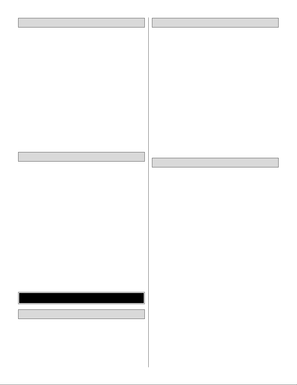
A building stand or cradle comes in handy during the build.
We use the Robart Super Stand II (ROBP1402) for all our
projects and it can be seen in pictures throughout this manual.
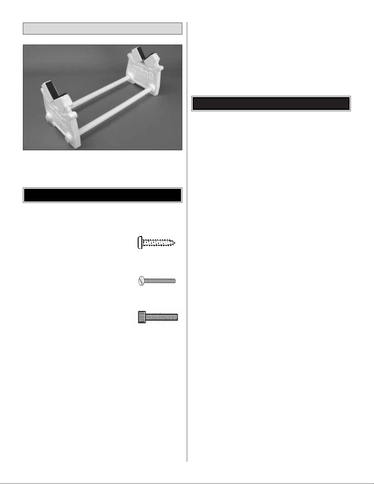
• There are three types of screws used in this kit:
Sheet metal screws are designated by a number and a
length. For example #6 x 3/4" [19mm]
This is a number six screw that is 3/4
"
[19mm] long.
Machine screws are designated by a number, threads per
inch and a length. For example 4-40 x 3/4" [19mm]
This is a number four screw that is 3/4"
[19mm] long with forty threads per inch
.
Socket head cap screwsare designated by a number , threads
per inch and a length.For example 4-40 x 3/4" [19mm]
This is a number four screw that is 3/4"
[19mm] long with forty threads per inch
.
• When you see the term
test fit
in the instructions, it
means that you should first position the part on the
assembly without using any glue, then slightly modify or
custom fit
the part as necessar y for the best fit.
• Whenever the term
glue
is written you should rely upon
your experience to decide what type of glue to use.When a
specific type of adhesive works best for that step, the
instructions will make a recommendation.
• Whenever just
epoxy
is specified you may use
either
30minute (or 45-minute) epoxy or6-minute epoxy. When 30minute epoxy is specified it is highly recommended that you
use only 30-minute (or 45-minute) epoxy, because you will
need the working time and/or the additional strength.
• Photos and sketches are placed before the step they
refer to. Frequently you can study photos in following steps
to get another view of the same parts.
• The stabilizer and wing incidences and engine thrust
angles have been factory-built into this model. However,
some technically-minded modelers may wish to check these
measurements anyway.To view this information visit the web
site at www.greatplanes.com and click on “Technical Data. ”
Due to manufacturing tolerances which will have little or no
effect on the way your model will fly, please expect slight
deviations between your model and the published values.
Replacement parts for the Great Planes Reactor .46 3D
ARF are available using the order numbers in the
Replacement Parts List that follows. The fastest, most
economical service can be provided by your hobby dealer or
mail-order company.
To locate a hobby dealer, visit the Hobbico web site at
www.hobbico.com. Choose “Where to Buy” at the bottom
of the menu on the left side of the page. Follow the
instructions provided on the page to locate a U.S., Canadian
or International dealer.
Parts may also be ordered directly from Hobby Services by
calling (217) 398-0007, or via facsimile at (217) 398-7721,
but full retail prices and shipping and handling charges will
apply. Illinois and Nevada residents will also be charged
sales tax. If ordering via fax, include a Visa®or MasterCard
®
number and expiration date for payment.
Mail parts orders and payments by personal check to:
Hobby Services
3002 N. Apollo Drive, Suite 1
Champaign, IL 61822
Be certain to specify the order number exactly as listed in
the Replacement Parts List. Payment by credit card or
personal check only; no C.O.D.
If additional assistance is required for any reason contact Product
Support by e-mail at productsupport@greatplanes.com, or
by telephone at (217) 398-8970.
Replacement Parts List
Order Number Description How to Purchase
Missing pieces Contact Product Support
Instruction manual Contact Product Support
Full-size plans Not available
GPMA2956 Wing Set w/o Joiner Tube
GPMA2957 Fuselage
GPMA2958 Tail Surface Set
GPMA2959 Wing Joiner Tube
GPMA2960 Cowl
GPMA2961 Canopy
GPMA2962 Landing Gear Set (L&R)
GPMA2963 Wheelpants Set (L&R)
GPMA2964 Decal Sheet
GPMA2965 Battery/ Radio Hatch
ORDERING REPLACEMENT PARTS
IMPORTANT BUILDING NOTES
Building Stand
5
Page 6
6
Before starting to build, take an inventory of this kit to make sure it is complete, and inspect the parts to make sure they
are of acceptable quality. If any parts are missing or are not of acceptable quality, or if you need assistance with assembly ,
contact Product Support. When reporting defective or missing parts, use the part names exactly as they are written in
the Kit Contents list.
Great Planes Product Support
3002 N. Apollo Drive, Suite 1
Champaign, IL 61822
Telephone: (217) 398-8970, ext. 5
Fax:(217) 398-7721
E-mail: airsupport@greatplanes.com
KIT INSPECTION
Tail Wheel Assembly
2-1/4" [57mm] Red Spinner Assembly
Wood Anti-Rotation Dowels (4)
Plywood Throttle Servo Tray
Plywood Throttle Servo Adapter Plates (2)
Plywood Outer Pushrod Tube Clip
1/4"x1/4"x12" [6x6x305mm] Balsa Stick
Battery Hatch Door
6mm Diameter Magnets (8)
2-5/64"x2-3/4"x5/64" [53x71.5x2mm]
Cooling Hole Coverplate
18" [457mm] Hook & Loop Strap
6" [150mm] Adhesive-Backed Hook &
Loop Material
3x8mm Round Head Machine Screws (4)
Large Control Horns (5)
12" [305mm] 2-56 Threaded One-End
Pushrods (5)
2-56 Faslinks (5)
#2x1/2" [13mm] Phillips Screws (10)
Silicone Clevis Retainers (6)
Nylon Clevises 2-56 (6)
6-32x1/2" [13mm] SHCS (4)
.40-.70 Nylon Engine Mount Halves (2)
#6 Flat Washers (12)
#6 Lock Washers (12)
6-32 Blind Nuts (4)
4-40x1/2" [13mm] SHCS (4)
#4 Flat Washers (4)
6-32x3/4" [19mm] SHCS (8)
#2 x 3/8" [9.5mm] Phillips Screws (10)
#2 Flat Washers (10)
2x9" [51x229mm] CA Hinge Strip
5/32"x1-1/4" [4x32mm] Axles (2)
Large Axle Nuts 5/16"–24 (2)
5/32" [4mm] Wheel Collars (4)
6-32 Set Screws (4)
4-40x3/8" [9.5mm] Machine Screws (4)
#4 Lock Washers (4)
Aluminum Fuel Line Plug
36" [914mm] 2-56 Threaded One-End
Pushrod
3/8" [9.5mm] Black Heat Shrink Tubing (3)
Brass Screw-Lock Connector
Brass Screw-Lock Connector Retainer
4-40x1/8" [3mm] SHCS
Outer Pushrod Tube 36" [914mm]
Kit Contents (Not Photographed)
KIT CONTENTS
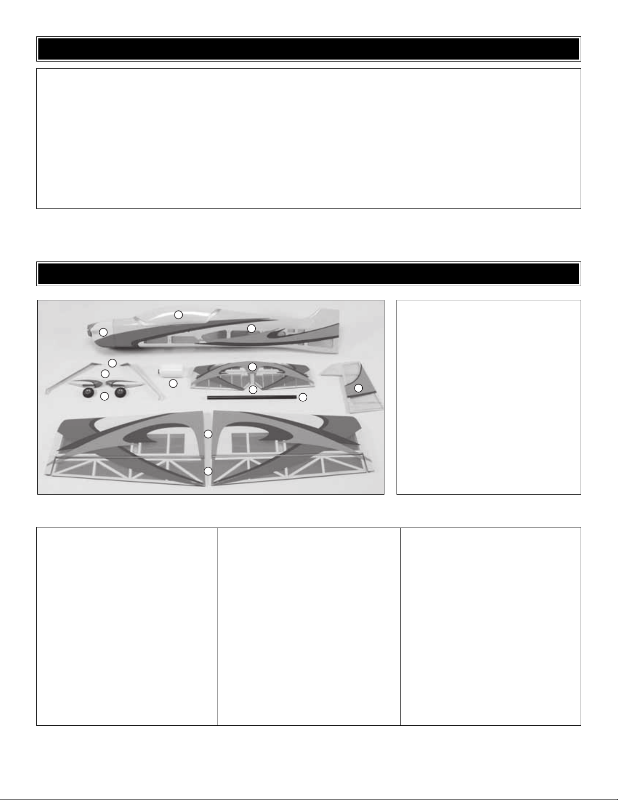
Kit Contents
1. Wing Halves (Left & Right)
2. Main Landing Gear (Left & Right)
3. Wheel Pants (Left & Right)
4. Main Wheels (2)
5. Fuel Tank
6. Aluminum Wing Tube
7. Horizontal Stabilizer
8. Rudder
9. Fuselage
10. Canopy
11. Cowl
12. Ailerons (Left & Right)
13. Elevators (Left & Right)
10
11
2
3
5
4
1
12
9
7
13
6
8
Page 7
❏ 1. If you have not done so already, remove the major
parts of the kit from the box and inspect for damage. If any
parts are damaged or missing, contact Product Suppor t at
the address or telephone number listed in the “Kit
Inspection” section on page 6.
❏ 2. Carefully remove the tape and separate all the control
surfaces. Use a covering iron with a covering sock on
medium/high heat to tighten the covering if necessary.Apply
pressure over sheeted areas to thoroughly bond the
covering to the wood.
Do the left wing first so your work matches the photos
the first time through.You can do one wing at a time, or
work on them together.
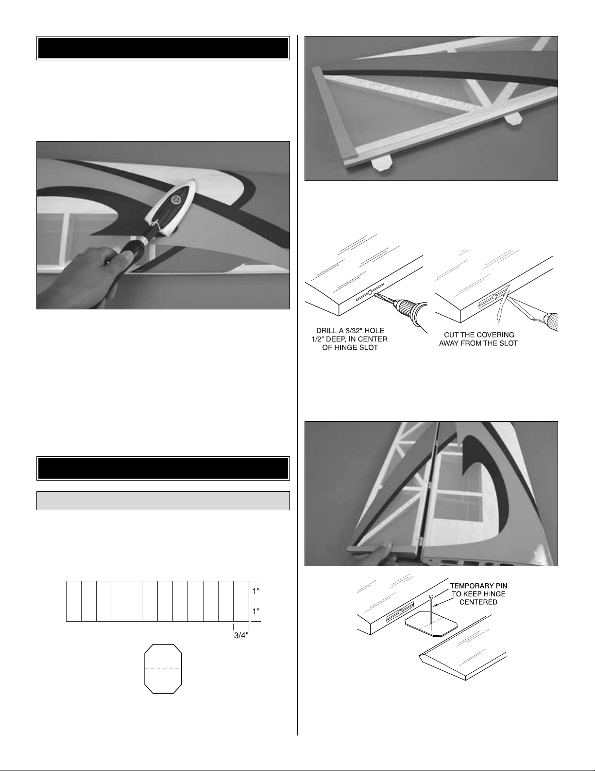
❏ ❏ 1.Cut the included 2 x 9" [51 x 229mm] CA hinge strip
into 3/4" x 1" [19 x 25mm] pieces.Trim the corners as shown
in the sketch.
❏ ❏ 2.Test fit the hinges into the aileron and wing panel.
If the hinges are difficult to insert, enlarge the hinge slots
with a sharp hobby knife.
❏ ❏ 3. Using a 3/32" [2.4mm] drill bit, drill a 1/2" [13mm]
deep hole in the center of each hinge slot. Cut away the
covering from just around each hinge slot with a sharp
hobby knife as shown.
❏ ❏ 4. Reinser t the hinges half way into the aileron hinge
slots.Stick a T-pin through the middle of each hinge in order to
keep them centered. Join the aileron to the wing panel and
remove the T-pins.Push the aileron against the wing hinge line.
Install the Ailerons
ASSEMBLE THE WING
PREPARATIONS
7
Page 8
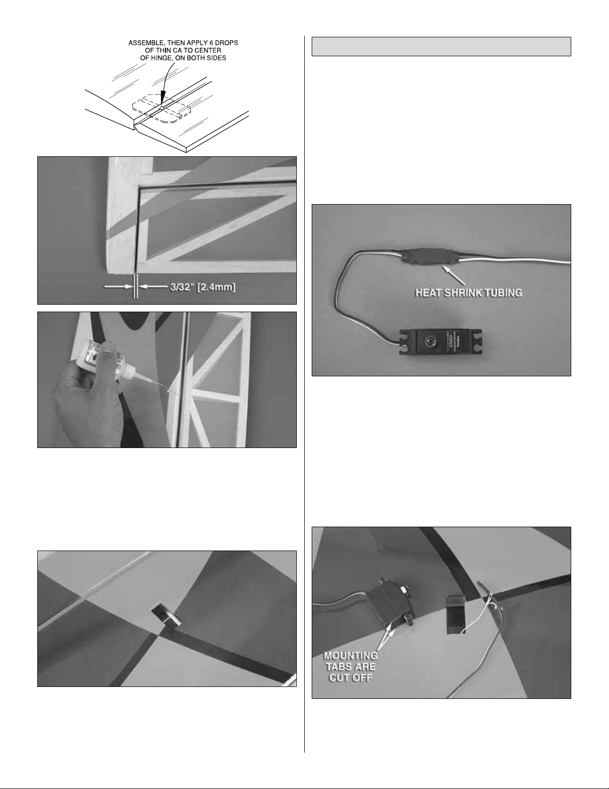
❏ ❏ 5. Confir m that there is a 3/32" [2.4mm] gap between
the outside end of the aileron and the wing tip.If not, adjust
the aileron as necessary for the proper gap.When satisfied,
deflect the aileron down far enough to obtain the 3D throws
recommended on page 28 and apply 6 drops of thin CA glue
to the center of each hinge. Flip the wing panel over and
apply 6 more drops to the underside of each hinge.
❏ ❏ 6. Cut the covering 1/8" [3mm] inside the opening in
the wing for the aileron servo. Use a covering iron or trim
iron to seal the covering to the inner edges of the opening.
❏ 7. Repeat these steps for the right wing panel.
❏ ❏ 1. Installing the servos in the wing will require the use
of one 12" [305 mm] servo extension for each aileron servo.
One Y-harness connector is required and is used to allow
the aileron servos to plug into one slot in your receiver.You
may have a computer radio that allows you to plug the
servos into separate slots and then mix them together with
the radio transmitter .If y ou choose to mix them together with
the radio rather than a Y-harness, refer to the manual for
your particular model radio system.
❏ ❏ 2. Attach the 12" [305 mm] servo extension to the
aileron servo and secure it with a piece of the included large
heat shrink tubing. The tubing can be shrunk around the
connector with a heat gun or micro torch.Only 1-1/2" [38 mm]
of heat shrink tubing is required for each connector. If your
aileron servo has tabs molded into the case for mounting the
servo on its side, they must be cut off in order for the servo
to fit into the servo bay in the wing panel. Follow the
instructions included with the servo for cutting the tabs.Install
the eyelets and grommets included with the servo.
❏ ❏ 3. Securely tie the string from inside the opening for
the aileron servo to the end of the servo extension.Remove
the tape holding the other end of the string to the wing root
rib and pull the servo wire and extension through the wing.
Install the Aileron Servos and Pushrods
8
Page 9
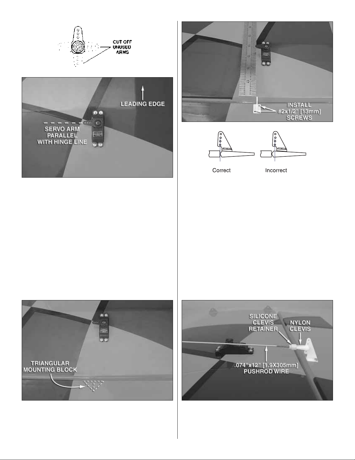
❏ ❏ 4.Temporarily position the aileron ser vo into the servo
bay with the servo spline towards the leading edge of the
wing. Drill a 1/16" [1.6 mm] hole through the four mounting
holes of the servo, drilling through the plywood mounting
plate in the wing. Install and remove a servo mounting screw
into each of the four holes. Apply a drop of thin CA into the
holes to harden the wood. After the glue has hardened,
install the servo into the opening.Cut three arms from a fourarmed servo arm (arms may need to be purchased
separately). Center the servo with your radio system and
install a servo arm parallel to the aileron hinge line as shown.
❏ ❏ 5.The aileron has a triangular block for mounting the
control horn. You can see the outline of it underneath the
covering by looking at the aileron at a shallow angle. If you
cannot see it, use your finger to lightly push in on the
covering until you find the edges of the mounting block.
❏ ❏ 6. Place a large nylon control horn on the aileron,
positioning it as shown in the sketch and aligning it with the
servo arm using a straight edge as a guide.Mark the location
for the screw holes.Using a 1/16" [2.4mm] drill bit, drill a 1/2"
[13mm] deep hole at the marks you made. (Be sure you are
drilling into the triangular mounting block on the bottom of the
aileron. Do not drill all the way through the aileron!).
Install and remove a #2 x 1/2" [13mm] sheet metal screw into
each of the holes. Harden the holes with a drop of thin CA.
After the glue has hardened completely, install the control
horn with two #2 x 1/2" [13mm] sheet metal screws.
❏ ❏ 7. Locate a .074" x 12" [1.9 x 305mm] pushrod wire
threaded on one end. Screw a nylon clevis onto the rod 20
complete turns. Slide a silicone clevis retainer onto the base
of the clevis.Connect the clevis to the second hole from the
bottom in the control horn.
9
Page 10
❏ ❏ 8. Use tape or a small clamp to hold the aileron in the
neutral position.With the servo arm still parallel to the hinge
line, make a mark on the pushrod where it crosses the outer
hole in the servo arm. Remove the pushrod and clevis from
the control horn and make a 90 degree bend at your mark.
Cut off the excess pushrod wire 1/4" [6mm] beyond the
bend. Enlarge the outer hole in the ser vo arm using a 5/64"
[2mm] drill bit. Connect the pushrod to the servo arm using
a nylon FasLink. Slide the silicone clevis retainer up to the
end of the clevis.
❏ 9. Repeat these steps for the right wing panel.
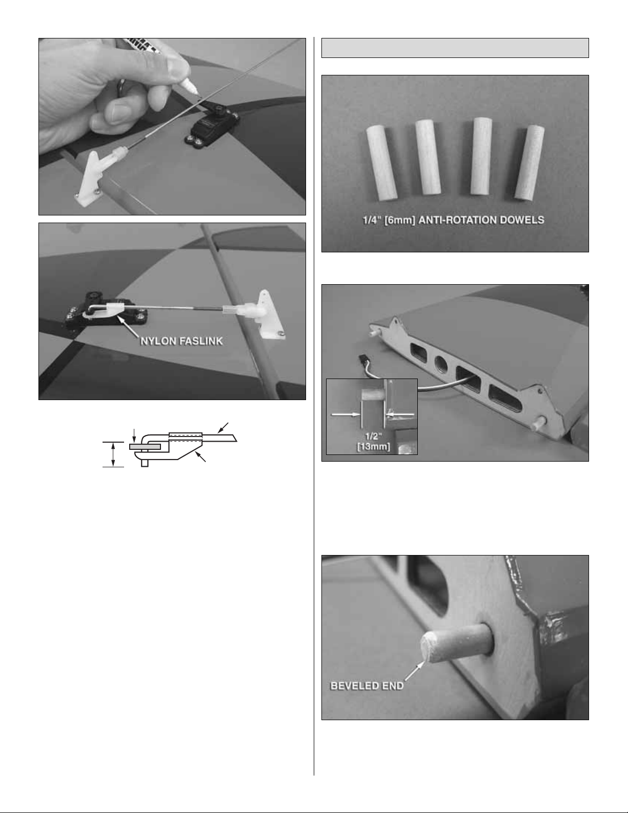
❏ 1.Locate the f our 1/4" [6mm] diameter anti-rotation do wels.
❏ ❏ 2.Coat half of two anti-rotation dowels with epoxy and
insert them into the forward and aft holes in the wing panel
root rib.It may be necessary to carefully tap them into place
with a mallet. The dowels should extend out approximately
1/2" [13mm]. Wipe away any excess epoxy with denatured
alcohol before the epoxy cures.
❏ ❏ 3.Use sandpaper to bevel the ends of the anti-rotation
dowels to ease their insertion into the fuselage.
❏ 4. Repeat steps 2 and 3 for the right wing panel.
Finish the Wing
10
Servo Arm
1/4” [6mm]
2-56(.074") Pushrod Wire
Faslink
Page 11
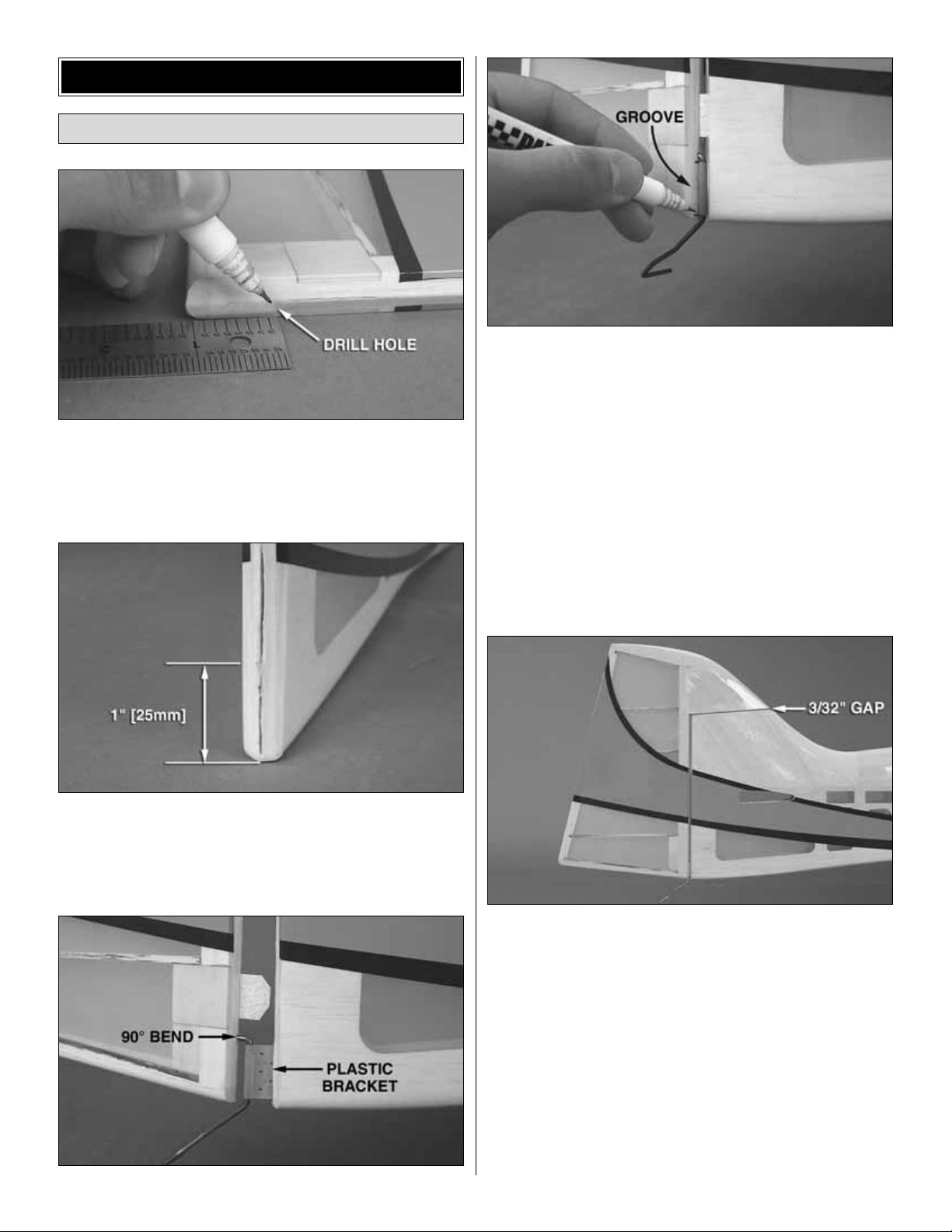
❏ 1. Make a mark 1-1/8" [28.4mm] from the bottom edge of
the rudder at the center of the hinge line. Carefully drill a
3/32" [2.4mm] diameter hole 1" [25mm] deep at the mark
perpendicular to the hinge line. Be sure that your hole is
drilled straight into the rudder.
❏ 2. Make a mark 1" [25mm] from the bottom edge of the
fuselage at the center of the rudder hinge line. Draw a line
down from that mark to just above the bottom of the fuse.
Use a hobby knife to cut a slot 1/32" [0.8mm] wide and 1/2"
[13mm] deep along the line you drew.
❏ 3. Test fit the plastic bracket of the tail gear assembly
into the slot in the fuselage. Temporarily install CA hinges
into the rudder. Guide the 90 degree bend in the tail gear
wire into the hole you drilled in the rudder and fit the rudder
into place with CA hinges as far as it will go (do not glue the
hinges yet).Mark the location on the rudder where a groove
will need to be carved to accommodate the plastic bracket.
❏ 4. Carve a groove at your marks until the rudder can fit
up against the fuselage.When satisfied with the fit, prepare
the hinge slots in the rudder and fuselage by enlarging them
as necessary with a sharp hobby knife.Drill a 3/32" [2.4mm]
diameter hole 1/2" [13mm] deep in the center of each hinge
slot.Using a hobby knif e, cut a wa y the co vering around each
hinge slot. Apply a couple drops of oil or petroleum jelly to
the wire near the plastic bracket. Coat the 90 degree bend
in the tail gear wire and the plastic bracket with medium CA
glue and join the rudder to the fuse with CA hinges. As you
did with the ailerons, apply thin CA to the rudder hinges,
being sure that you can obtain the 3D throws listed on page
28. Leave a 3/32" [2.4mm] gap between the top of the
fuselage fin and the rudder.
Install the Rudder and Tail Gear
ASSEMBLE THE FUSELAGE
11
Page 12

❏ 5. Install the tail wheel onto the tail wheel wire followed
by the wheel collar and set screw. Spin the tail wheel and
confirm that it rotates freely. Oil the tail wheel as necessar y
for it to spin smoothly.
❏ 1.Attach the 5/32" [4mm] axles to the main landing gear
using 5/16"-24 axle nuts. Slide a 5/32" [4mm] wheel collar
onto each axle followed by a 2-1/4" [57mm] foam wheel and
another 5/32" [4mm] wheel collar.Loosely screw a 6-32 set
screw into each wheel collar using a 1/16" [1.6mm] allen key.
❏ 2. Slide the wheel pants over the axles into position and
temporarily attach them to the landing gear using four
4-40 x 3/8" [9.5mm] phillips screws.P osition the wheel in the
center of the wheel cutout in the wheel pants and tighten the
wheel collars against the axles.
❏ 3. Remove the wheel pants from the landing gear and
remove the wheel collars and wheels from the axles.Locate
the indentations on the axles made by tightening the set
screws. Use a metal file or rotar y tool such as a Dremel to
grind flat spots on the axles at the indentations.
❏ 4.Reassemble the wheel collars and wheels onto the axles.
Apply threadlocking compound to the set screws. Attach the
wheel pants to the main landing gear using the four 4-40 x 3/8"
[9.5mm] screws and four #4 loc k washers .Apply threadloc king
compound to the screws before tightening.Center the wheels
in the wheel pants and tighten the set screws in the wheel
collars.Oil the wheels as necessary for them to spin smoothly.
Assemble and Install the Main Gear
12
Page 13

❏ 5. Trim the covering from the landing gear slots in the
fuselage using a sharp hobby knife.
❏ 6. Install the landing gear into the fuselage using four 6-
32 x 1/2" [13mm] SHCS, four #6 flat washers, four #6 lock
washers and threadlocking compound.
❏ 1. Just as you did with the ailerons and rudder, prepare
the hinge slots in the horizontal stabilizer and elevators by
enlarging the slots as necessary, drilling a 3/32" [2.4mm]
hole at the center of each slot and trimming away the
covering from around each slot.
❏ 2. Locate the stabilizer slots near the aft end of the
fuselage and carefully trim away the covering.
❏ 3. In order to align the stab in the fuselage, the wing
panels will need to be temporarily installed. Trim the
covering from the screw holes in the wing panel root ribs.
❏ 4.Slide the black alumin um wing tube into the fiberglass
joiner tube inside the fuselage and center its position. Install
the wing panels onto the tube and slide them into the wing
pockets in the fuselage.
Install the Elevators and Horizontal Stab
13
Page 14

❏ 5. Secure the wings to the fuse using four 4-40 x 1/2"
[13mm] SHCS and four #4 flat washers.
❏ 6.Test fit the stabilizer in the fuselage. Center the stab left
and right in the fuselage. Stand back sever al feet behind the
model and check to be sure the stab is parallel to the wing.
Adjust the stab saddle as needed until the stab and wing are
parallel.Weight can be added to one side of the stabilizer to
bring the stab parallel to the wing.When the stab is glued in
place permanently, the same amount of weight should be
added while the glue hardens.
❏ 7. Measure the distance from the tip of each wing to the
tip of the stab.Adjust the stab until the distance from the tip
of the stab to the tip of the wing is equal on both sides.
❏ 8.Use a felt tip marker to mark the outline of the fuselage
onto the top and bottom of the stab.
❏ 9.Remove the stab from the fuse.Use a sharp #11 hobby
knife or use the following Expert Tip to cut the covering
1/16" [1.6mm] inside of the lines you marked. Use care to
cut only in the covering and not into the wood.
CC
14
C = C
Page 15

HOW TO CUT COVERING FROM BALSA
Use a soldering iron to cut the covering from the stab.The
tip of the soldering iron doesn’t have to be sharp, but a fine
tip does work best. Allow the iron to heat fully.
Use a straightedge to guide the soldering iron at a rate that
will just melt the covering and not burn into the wood. The
hotter the soldering iron, the faster it must travel to melt a
fine cut. Peel off the covering
❏ 10. Use 30-minute epoxy to glue the stab into the
fuselage.For the most strength, apply epo xy to both sides of
the stab and inside the fuse where the stab fits. Slide the
stab into position and confirm that the stab is still properly
aligned. Wipe away any excess epoxy and the marks you
made with a paper towel and denatured alcohol. Do not
disturb the model until the epoxy has fully hardened.
❏ 11. As you did with the ailerons and rudder, attach the
elevator halves to the horizontal stabilizer with CA hinges.
Refer to the 3D control throws on page 28 when gluing the
CA hinges. Be sure to leave a 3/32" [2.4mm] gap between
the ends of the stab and the elevator halves.
❏ 1.Locate the six servo bays beneath the cov e ring in front
of the horizontal stabilizer (three per side) in the fuselage.
Only three of these will be used (two for the ele vator, one for
the rudder). Cut the covering from the top-aft bay from the
left side of the fuse and cut the covering from the topforward bay as well as the bottom bay on the right side as
shown. Make your cuts 1/8" [3mm] inside the openings and
use an iron to seal the covering over the edges.
❏ 2.If you are installing servos that are larger than the servo
bays, use the sketch as a guide to enlarge the openings.
Cutting the shaded portions as needed will ensure that you
will have adequate plywood remaining along side the
openings to secure the servos in the fuselage.
❏ 3. Attach 24" [610mm] servo extensions to the two
elevator servos and rudder servo. Use heat shrink tubing to
secure the connectors.
Install the Tail Servos and Pushrods
15
SHADED PORTION
Page 16

❏ 4. Feed the servo extensions through the fuselage
formers to the fuselage hatch and mount the servos into the
servo bays with the servo splines facing forward using the
hardware included with the servos. Be sure to reinforce the
servo screw holes with thin CA.
❏ ❏ 5.Center the servos with your radio system and attach
servo arms pointing down. Using the same procedure as the
ailerons, make up three pushrods using three 12" [305mm]
rods, three nylon clevises and three silicone clevis retainers.
Attach the clevises from two of the pushrods to the outer
holes in the elevator servo arms in order to use the pushrods
as a straight edge.
❏ ❏ 6. Align the elevator pushrods parallel with the fuselage
over the elevator halves. Use the position of the pushrods to
mark the locations for the elevator control horns. The elevator
control horns should be positioned over the plywood mounting
plate.The plate is visible from the top of the elevators. Using a
1/16" [2.4mm] drill bit, make a 1/2" [13mm] deep hole at the
marks you made, being sure not to drill completely through the
elevators. Install and remove a #2 x 1/2" [13mm] sheet metal
screw into each of the holes.Harden the holes with a drop of thin
CA. After the glue has hardened completely, install the control
horns with four #2 x 1/2" [13mm] sheet metal screws.
❏ ❏ 7. As you did with the ailerons, enlarge the outer holes
in the elevator servo arms using a 5/64" [2mm] bit. Connect
the clevises to the second from the bottom holes in the
control horns and mark the location where the elevator
pushrods cross the outer holes in the servo arms with the
elevators in the neutral position.Bend the pushrods at a 90
degree angle and cut off the excess rod leaving 1/4" [6mm].
Attach the pushrods to the servo arms with nylon Faslinks.
❏ 8. Repeat steps 5-7 for the rudder pushrod. Be careful
when drilling the holes for the rudder control horn as the
rudder is approximately 1/2" [13mm] thick at the control horn
mounting plate. To avoid accidentally drilling completely
through the rudder, drill the holes for the control horn only
3/8" [9.5mm] deep. The thickness of the control horn will
prevent the #2 x 1/2" [13mm] screws from passing through
the other side of the rudder.
16
Page 17

Detailed installation instructions are provided in this manual
for both the Great Planes C42-60-480kV RimFire brushless
motor and the O.S. FS-70 Surpass II four-stroke glow
engine. A two-stroke engine can also be installed, but
detailed instructions are not included. Use the four-stroke
instructions as a guide for a 2-stroke installation.
The Reactor .46 ARF can be changed from a glow engine
setup to a brushless motor or vice-versa with little difficulty,
so your power plant choice during original assembly does
not have to be permanent. To switch from one to the other,
simply remove the components installed specifically for the
original power plant and follow the instructions in this
manual for the other type. The mounting pattern for the
electric motor mount recommended for the Great Planes
C42-60-480kV RimFire motor is the same as the included
.40-.70 nylon engine mount, so new holes don’t need to be
drilled into the firewall when making the switch.
❏ 1. Cut out the mounting template from the back of this
manual.Before using the template to mark your holes on the
firewall, consider now if you may install a two-stroke or fourstroke engine in the future. If you prefer using a four-stroke
engine, align the mounting template over the vertical and
horizontal lines on the firewall and use clear tape to hold it in
place. If you prefer a two-stroke, position the template over
the lines on the firewall set at a 45 degree angle (making this
choice now will prev ent you from ha ving to drill new mounting
holes when switching to a glow engine). Push a sharp T-pin
into each of the four mounting hole locations on the template
marking their position on the firewall.
❏ 2. Drill 3/16" [4.8mm] holes at the marks you made. To
reduce tear-out from the back of the holes and to ensure
accuracy, drill smaller pilot holes at the marks first, then
enlarge the holes to 3/16" [4.8mm].Insert a 6-32 blind nut into
each of the four holes and draw them tight into the firewall
using a 6-32 x 3/4" [19mm] SHCS and #6 flat washer.
❏ 3. Using the four 3 x 8mm machine screws included with
the kit and threadlocking compound, secure the motor to the
motor mount as shown.
❏ 4. Attach the motor mount to the firewall using four
6-32 x 3/4" [19mm] SHCS, four #6 flat washers, four #6 lock
washers, and threadlocking compound.
Brushless Motor Installation
ENGINE INSTALLATION
17
Page 18

❏ 5. Attach the prop adapter with the screws included with
the motor.Be sure to use threadlocking compound.
❏ 6. Loosen the screws that connect the two halves of the
motor mount together. Adjust the mount so that the front of
the prop adapter is 4-15/16" [125mm] from the firewall.
❏ 7. When tightening the screws, be sure that you do not
inadvertently create any up or down thrust for the motor .The
motor should be parallel with the horizontal stabilizer (zero
degrees down thrust). Use an incidence meter to check the
thrust angle of the motor against the stab.If you do not have
an incidence meter, align the slots in the center of the two
motor mount halves when tightening the screws.Be sure to
use threadlocking compound.
❏ 8. Secure the ESC to the plane in the location shown and
connect it to the motor.You may need to use a scrap piece of
balsa to lower the ESC in order for it to fit part way through the
cooling hole cutout. We used foam servo tape (not included)
to secure the ESC.
Note: The ESC shown may be different in
size and shape than the ESC suggested in this manual.
❏ 1. Cut out the mounting template from the back of this
manual. Align the mounting template over the vertical and
horizontal lines on the firewall and use clear tape to hold it in
place. If you are installing a two-stroke engine, position the
template over the lines on the firew all set at a 45 deg ree angle.
Push a sharp T-pin into each of the four mounting hole locations
on the template, marking their position on the firewall.
Four-Stroke Glow Engine Installation
18
Page 19

❏ 2. Drill 3/16" [4.8mm] holes at the mar ks you made. To
reduce tear-out from the back of the holes and to ensure
accuracy, drill smaller pilot holes at the marks first, then
enlarge the holes to 3/16" [4.8mm]. Inser t a 6-32 blind nut
into each of the four holes and draw them tight into the
firewall using a 6-32 x 3/4" [19mm] SHCS and #6 flat washer.
❏ 3. Loosely attach the nylon engine mount inverted to
the firewall using four 6-32 x 3/4" [19mm] SHCS, four #6 flat
washers and four #6 lock washers.
❏ 4. Fit your engine between the engine mount rails, slide
the rails against the engine crankcase, remove the engine
and tighten down the engine mount screws. Place the
engine back onto the mount and position it so that the front
of the drive washer is 4-15/16" [125mm] from the firewall.
❏ 5. Use the Great Planes Dead Center
™
Hole Locator to
mark the engine mounting holes onto the engine mount.
❏ 6. Drill and tap 6-32 holes for the engine mount screws at
the marks you made. Secure the muffler to the engine. In
order to route the muffler along the bottom of the fuselage,
we used an optional O.S. Inside Exhaust Manifold, part
number OSMG2624. Without the manifold, the muffler will
exit the along the side of the fuselage and a portion of the
cowl will need to be cut away for the muffler to pass through.
Attach the engine to the mount using four 6-32 x 3/4" [19mm]
SHCS, four #6 flat washers and four #6 lock washers.
❏ 1.Locate the fuel tank. The hardware needed for the fuel
tank assembly is inside of the tank.Remove the stopper and
shake out the contents.
❏ 2.The fuel tank for the Reactor utilizes a three line system.
There is a fill line, carb line, and vent line (to muffler).The
fill line will allow fueling and defueling without unhooking any
fuel lines. The fill line is optional and may be omitted if
desired, or a fuel fill valve may be installed (not included).
❏ 3. Slide the three aluminum fuel tubes into the
rubber stopper.
Install the Fuel Tank and Throttle Servo
19
Page 20

❏ 4. Cut the fill line and carb line tubes such that the tubes
extend 1/2" [13mm] out from both ends of the stopper. Install
the metal plates on the front and back of the stopper and
loosely thread the 3 x 26mm phillips machine screw through
the plates.The vent line should be bent upward and left uncut.
❏ 5. Attach a silicone fuel line 6" [152mm] in length to the
carb line tube and fill line tube in the stopper. Install the
included fuel clunks onto these lines.
❏ 6.Insert the stopper into the tank and check the length of
the carb line and fill lines. The clunks should almost rest
against the back of the tank when the stopper is in place but
move freely and the vent line should point towards (but not
touch) the top of the tank. Adjust the length of the fuel lines
until the proper length has been reached. Also check that
the vent line is bent upward enough to reach the top of the
fuel tank. Once you are satisfied with the fit, secure the
stopper to the tank using the Phillips head screw in the
stopper assembly. Be careful not to over tighten as the fuel
tank could split.Now would be a good time to mark the lines
on the tank, as well as which side of the tank should face up .
❏ 7. Slide 6" [152mm] of fuel tubing onto each of the tubes
in the fuel tank. Feed the fuel tubing through the hole in the
firewall from the inside of the fuselage. Inser t the fuel tank
into position, being sure that the neck of the fuel tank is fully
inserted through the hole in the firewall and the correct side
is facing up.
❏ 8.Locate the 1/4" x 1/4" x 12" [6 x 6 x 305mm] balsa stick
and cut a piece 3-5/8" [92mm] long. Glue the piece tightly
behind the fuel tank as shown.
20
TOP OF TANK
VENT
FILL AND CARB LINES
Page 21

❏ 9.Cut another piece 4" [102mm] long and two pieces 3/8"
[9.5mm] long. Glue the small pieces in the location shown.
Glue the 4" [102mm] piece to the small pieces across the
fuel tank.Confirm that the fuel tank is held securely in place.
❏ 10.Make a mark on the firewall in line with the throttle arm
on the carburetor. Use a 3/16" [4.8mm] bit to drill a hole
through the firewall at the mark you made. Be sure that you
are not drilling through the fuel tank! If necessary, move your
mark below or to the side of the fuel tank.The throttle pushrod
can be bent after installation to reach the throttle arm.
❏ 11.A throttle servo tra y and two servo adapter plates are
included in the kit.The small adapter plate will hold a 1.1" x 0.5"
[28 x 13mm] micro servo such as the Futaba S3101.The large
adapter plate will hold a 1.4" x 0.6" [36 x 15mm] servo such as
the Futaba S9650. The throttle servo tray will hold a standard
size servo (1.6" [40.5mm] long) such as the Futaba S3003.
Glue the throttle servo tray into position as shown.
❏ 12.Temporarily insert the 3/16" [4.8mm] outer pushrod tube
through the hole in the firewall and slide it back to the throttle
servo tray. With the outer pushrod tube straight, determine
where your throttle servo will need to be installed. Mark the
portion of the battery tray abov e the location of the throttle servo
that will need to be cut away in order to make room for it.
❏ 13. Cut away the battery tray at the marks you made
using a Dremel tool or a hobby knife and test fit your servo
into the throttle servo tray.When satisfied, secure the throttle
servo to the servo tray using the hardware included with the
servo. If you are using an adapter plate, glue it to the servo
tray using medium CA glue.
21
Page 22

❏ 14. Position the outer pushrod tube so that the aft end is
approximately 1/4" [6mm] behind the front edge of the throttle
servo tray. Mark the tube at the firewall, remove it from the
plane and cut it to length at the mark you made. Use
sandpaper to roughen the ends of the pushrod tube, reinstall
it into the plane and glue the front end to the firewall.
❏ 15.Attach a nylon cle vis and a silicone cle vis retainer to a 36"
[914mm] pushrod.Install a brass screw-lock connector onto the
throttle servo arm and secure it using a nylon retainer.Thread a
4-40 x 1/8" [3mm] SHCS loosely into the screw-lock connector.
Slide the pushrod through the aft end of the outer pushrod tube
and through the screw-lock connector on the throttle arm.
Connect the clevis to your throttle servo and adjust the positions
of the throttle arm on the carb and throttle servo arm. Use your
radio to ensure complete carb barrel rotation.When satisfied, cut
off the excess pushrod beyond the screw-lock connector.
❏ 16.Clip the pushrod tube support onto the outer pushrod
tube near the throttle servo.Glue it to the pushrod tube and to
the throttle servo tray.
❏ 17. Glue the cooling hole cover in place as shown.
❏ 18. Finish the engine installation by connecting the fuel
lines to the muffler and carburetor .Use the included fuel line
plug for your fill line when not in use.
❏ 19. Two-stroke insatallation is similar.
The fuselage hatch has been designed to be easily
removable to allow you access to your radio equipment and
flight packs (if you have installed a brushless motor).
❏ 1. Glue four magnets into the fuselage hatch as shown
with CA glue. Be sure that the magnets are securely glued in
place. Roughing up the magnets with sandpaper before
installation will improve adhesion. Apply a thin coating of
medium CA glue into each magnet hole. Put the magnets in
place and apply a skin coating of thin CA across the top of the
magnets overlapping onto the wood just around the holes.
Allow the CA glue to dry undisturbed without accelerator.
Assemble the Fuselage Hatch
FINISH THE MODEL
22
Page 23

❏ 2. Install four magnets into the magnet holes in the
fuselage in the same manner as you did with the hatch. Be
sure to install the magnets with the polarity in the correct
direction! The magnets in the hatch must be attracted to the
magnets in the fuselage when installed. To avoid confusion,
put a magnet over each one that is glued in the hatch. Make
a mark on the magnet so you will know which side faces down
in relation to the battery hatch when gluing them into the
fuselage.Also , make note of each fuselage magnet and which
hole it will be glued into when marking it.
❏ 3.If you ha ve installed a brushless motor, trim the covering
from the cooling hole exit behind the fuselage hatch.This will
also allow you to reach your finger through the exit hole and
pop the fuselage hatch open in order to remove and replace
your flight packs. If you have a glow engine installed, use a
small screwdriver to pry the hatch open when occasional
access to your radio equipment is needed.
❏ 1.Make up two hook and loop str aps f or y our receiv er and
receiver battery pack by cutting the included hook and loop
material to length (use the size of your radio equipment as a
guide) and overlapping the ends together as shown.
❏ 2. In order to make room for the main flight packs, the
receiver and receiver battery must be installed on the top
side of the battery tray.You have some options to access the
top of the battery tray. For our model, we carefully trimmed
the covering 3/16" [4.8mm] outside the lightening hole
cutout as shown on three sides and peeled it back to expose
the top of the battery tray. You can also trim the covering
away from the lightening hole, then cover it up using a trim
sheet after the radio system is installed. Another option
would be to create a removable cockpit base (material not
included) that could be unscrewed to allow access to the
radio system should repair or replacement be necessary.
Install the Radio System (Brushless Motor)
23
Page 24

❏ 3. Feed the receiver antenna through the antenna tube
installed in the fuselage.T emporarily remov e the left ele vator
servo from the fuselage to expose the aft end of the antenna
tube. Use needle nose pliers to pull the rest of the antenna
when you get it far enough through to come out of the aft
end of the antenna tube. Guide the end of the antenna wire
into the cavity in the rear of the fuselage.
❏ 4. Wrap the receiver and receiver battery pack with foam
rubber (not included). Use the hook and loop straps you
made to secure them in the fuselage in the location shown.
❏ 5. Attach your receiver switch and charge jack receptacle
(not included) to the side of the fuselage. Be sure that the
receptacle you are installing will not interfere with the flight
packs.The Great Planes switch and charge jack receptacle is
too large for this plane.We used an Ernst charge receptacle,
part number ERNM3001. Hook your tail surface servos and
battery harness to the receiver. Confirm that your aileron Yharness is long enough for the ends to reach through the
sides of the fuselage to connect to the aileron servo
extensions. If not, you may need to install additional 6"
[152mm] servo extensions onto the harness. If you have a
computerized radio and will not be using a Y-harness, 6"
[152mm] servo extensions will be needed for the aileron
channels on your receiver.
❏ 6. Double check the radio system to be sure that
everything is in order and the radio system is working
properly. If you peeled back the covering like shown in step
#2, use a covering iron on low heat to seal it back down.
24
Page 25

❏ 7. Make a strap out of the remaining hook and loop
material for the flight packs. We have included adhesivebacked hook and loop material for added security for the
packs. However, you will want to check your C.G. position
(after the model is complete) before adhering the material to
the battery tray. The C.G. position can be changed by
moving the flight packs forward or aft inside the fuselage.
When satisfied with the battery position by confirming the
C.G., we suggest gluing the hook and loop strap to the
battery tray to prevent it from falling inside the fuselage
when changing flight packs.
❏ 1. Make up two hook and loop straps for your receiver
and receiver battery pack by overlapping the ends together
as shown.
❏ 2. Feed the receiver antenna through the antenna tube
installed in the fuselage.T emporarily remov e the left ele vator
servo from the fuselage to expose the aft end of the antenna
tube. Use needle nose pliers to pull the rest of the antenna
when you get it far enough in to come out of the aft end of
the antenna tube. Guide the antenna wire into the cavity in
the rear of the fuselage.
❏ 3. Wrap the receiver and receiver battery pack with foam
rubber (not included). Use the hook and loop straps you
made to secure them in the fuselage in the location shown.
Confirm that your aileron Y-harness is long enough for the
ends to reach through the sides of the fuselage to connect
to the aileron servo extensions. If not, you may need to
install additional 6" [152mm] servo extensions onto the
harness. If you have a computerized radio and will not be
using a Y-harness, 6" [152mm] servo extensions will be
needed for the aileron channels on your receiver.
❏ 4.Attach your receiver s witch and charge jack receptacle
(not included) to the side of the fuselage across from the
throttle servo.
Install the Radio System (Glow Engine)
25
Page 26

❏ 1.Use a rotary tool such as a Dremel to cut cooling holes
in the cowl to match your power system.If you are installing
a glow engine, you will need a hole f or the engine head, cool
air inlet and an access hole for your needle valve.
❏ 2.Put four strips of masking tape approximately 5" [127mm]
long (two pieces per side) onto the fuselage, in line with the
cowl mounting tabs as shown. Place a mark in the middle of
each piece of tape, centered over the cowl mounting tabs.
Measure 4" [102mm] back from those marks and make another
mark. Draw a line connecting your marks with a straight edge.
❏ 3.Fit the cowl onto the fuselage and temporarily secure the
spinner backplate onto the prop shaft.You may need to drill
out the hole in the backplate or use a prop reamer to match
the diameter of your prop shaft (6mm diameter for the C4260-480kV RimFire, 5/16" [7.9mm] for the O.S. .70 Surpass
four-stroke engine). Align the colors on the cowl with the
covering on the fuselage and position the cowl allowing a
3/32" [2.4mm] gap between the front of the cowl and the
spinner backplate.When satisfied, tape the cowl into position.
❏ 4. Measure 4" [102mm] from the aft marks you made on
the masking tape to determine the locations for the cowl
mounting screws. Using the straight lines on the tape as a
guide, mark the locations on the cowl for the four mounting
screws.Drill through the cowl and cowl mounting tabs at the
marks using a 1/16" [1.6mm] drill bit. Remove the cowl from
the fuselage (and the masking tape) and thread a #2 x 3/8"
[9.5mm] sheet metal screw into each hole in the cowl
mounting tabs and remove it.Add a drop of thin CA to each
hole to harden them.
Install the Cowl, Canopy and Spinner
26
Page 27

❏ 5.Attach the cowl with four #2 x 3/8" [9.5mm] scre ws and
four #2 flat washers. Install the propeller and spinner onto
the prop shaft using the hardware that came with the engine
or motor.
❏ 6. Align the canopy on the fuselage and use tape to hold
it in place.Drill six 1/16" [1.6mm] holes (three per side) along
the bottom edges of the canopy 3/16" [4.8mm] below the
cockpit base of the fuselage. Thread a #2 x 3/8" [9.5mm]
screw into each hole and back it out. Remove the canopy
and add a drop of thin CA glue to each hole. After the glue
has hardened, install the canopy using six #2 x 3/8" [9.5mm]
screws and six #2 flat washers.
1.Use scissors or a sharp hobby knife to cut the decals from
the sheet.
2. Be certain the model is clean and free from oily
fingerprints and dust. Prepare a dishpan or small bucket with
a mixture of liquid dish soap and warm water—about one
teaspoon of soap per gallon of water.Submerse the decal in
the soap and water and peel off the paper backing. Note:
Even though the decals hav e a “sticky-back”and are not the
water transfer type , submersing them in soap & water allo ws
accurate positioning and reduces air bubbles underneath.
3.Position the decals on the model where desired.Holding the
decal down, use a paper towel to wipe most of the water a wa y.
4. Use a piece of soft balsa or something similar to
squeegee remaining water from under the decal. Apply the
rest of the decals the same way.
❏ 1. Turn on the transmitter and receiver and center the
trims. If necessary, remove the servo arms from the servos
and reposition them so they are centered. Reinstall the
screws that hold on the servo arms.
❏ 2. With the transmitter and receiver still on, check all the
control surfaces to see if they are centered.If necessary, adjust
the clevises on the pushrods to center the control surfaces.
❏ 3. Make certain that the control surfaces and the throttle
respond in the correct direction as shown in the diagram. If
any of the controls respond in the wrong direction, use the
servo reversing in the transmitter to reverse the servos
connected to those controls. Be certain the control surfaces
have remained centered.Adjust if necessary.
Check the Control Directions
GET THE MODEL READY TO FLY
Apply the Decals
27
Page 28

Use a ruler to accurately measure and set the control throw
of each control surface as indicated in the chart that follows.
If your radio does not hav e dual rates, w e recommend setting
the throws at the low rate setting for the first few flights.
NOTE:The throws are measured at the widest part of the
elevators, rudder and ailerons.
At this stage the model should be in ready-to-fly condition
with all of the systems in place including the engine, landing
gear, covering and paint and the radio system.
❏ 1.Use a f elt-tip pen or 1/8" [3mm]-wide tape to accurately
mark the C.G. on the top of the wing on both sides of the
fuselage.The C.G. is located 4-3/4" [121mm] back from the
leading edge of the wing.
❏ 2. With the wing attached to the fuselage, all parts of the
model installed (ready to fly) and an empty fuel tank, place
the model upside-down on a Great Planes CG Machine, or
lift it upside-down at the balance point you marked.
❏ 3. If the tail drops, the model is “tail heavy” and the battery
pack(s) and/or receiver must be shifted f orward or w eight must
be added to the nose to balance.If the nose drops, the model
is “nose heavy” and the battery pack and/or receiver must be
shifted aft or weight must be added to the tail to balance (a
glow engine installation will most likely require 2 to 5 ounces of
tail weight to balance). If possible, relocate the battery pack
and receiver to minimize or eliminate any additional ballast
required. If additional weight is required, nose weight may be
easily added by using a “spinner weight” (GPMQ4645 for the
1 oz. [28g] weight, or GPMQ4646 for the 2 oz.[57g] weight).If
spinner weight is not practical or is not enough, use Great
Planes (GPMQ4485) “stick-on”lead. A good place to add stick-
This is where your model should balance for the first
flights. Later, you may wish to experiment by shifting the
C.G. up to 1/8" [3mm] forward or 1/4" [6mm] back to
change the flying characteristics. Moving the C.G.forward
may improve the smoothness and stability, but the model
may then require more speed for tak eoff and mak e it more
difficult to slow for landing.Moving the C.G.aft makes the
model more maneuverable, but could also cause it to
become too difficult to control. In any case, start at the
recommended balance point and do not at any time
balance the model outside the specified range.
More than any other factor, the C.G. (balance point) can
have the greatest effect on how a model flies and may
determine whether or not your first flight will be
successful. If you value this model and wish to enjoy it for
many flights, DO NOT OVERLOOK THIS IMPORTANT
PROCEDURE. A model that is not properly balanced will
be unstable and possibly unflyable.
Balance the Model (C.G.)
IMPORTANT: The Reactor .46 3D ARF has been
extensively flown and tested to arrive at the throws at which
it flies best. Flying your model at these throws will provide
you with the greatest chance for successful first flights. If,
after you have become accustomed to the way the Reactor
flies, you would like to change the throws to suit your taste,
that is fine.Howe v er, too much control throw could mak e the
model difficult to control for less experienced fliers, so
remember, “more is not always better.”
These are the recommended control surface throws:
High Rate Low Rate
ELEVATOR: 7/8" [22mm] up 7/16" [11mm] up
7/8" [22mm] down 7/16" [11mm] down
RUDDER: 4" [102mm] right 1" [25mm] right
4" [102mm] left 1" [25mm] left
AILERONS: 2" [51mm] up 1" [25mm] up
2" [51mm] down 1" [25mm] down
3D RATES
3D ELEVATOR: 2" [51mm] up
2" [51mm] down
3D RUDDER: 4" [102mm] right
4" [102mm] left
3D AILERONS: 3" [76mm] up
3" [76mm] down
Set the Control Throws
28
4-3/4" [121mm]
Page 29

on nose weight is to the firewall (don’t attach weight to the
cowl—it is not intended to support weight). Begin by placing
incrementally increasing amounts of weight on the bottom of
the fuse over the firewall until the model balances. Once you
have determined the amount of weight required, it can be
permanently attached. If required, tail weight may be added by
cutting open the fuse and gluing it permanently inside. Note:
Do not rely upon the adhesive on the back of the lead weight
to permanently hold it in place. Over time, fuel and exhaust
residue may soften the adhesive and cause the weight to f all
off. Use #2 sheet metal screws, RTV silicone or epoxy to
permanently hold the weight in place.
❏ 4. IMPORTANT: If you found it necessary to add any
weight, recheck the C.G.after the weight has been installed.
❏ 1. With the wing level, have an assistant help you lift the
model by the engine propeller shaft and the bottom of the
fuse under the TE of the fin.Do this several times.
❏ 2.If one wing alw ays drops when y ou lift the model, it means
that side is heavy. Balance the airplane by adding weight to the
other wing tip. An airplane that has been laterally balanced
will track better in loops and other maneuvers.
No matter if you fly at an AMA sanctioned R/C club site or if you
fly somewhere on your own, you should always have your
name, address, telephone number and AMA number on or
inside your model.It is requiredat all AMA R/C club flying sites
and AMA sanctioned flying events. Fill out the identification tag
on the decal sheet and place it on or inside your model.
Follow the battery charging instructions that came with your
radio control system to charge the batteries. You should
always charge your transmitter and receiver batteries the
night before you go flying and at other times as recommended
by the radio manufacturer.
Carefully balance your propeller and spare propellers before
you fly. An unbalanced prop can be the single most significant
cause of vibration that can damage your model. Not only will
engine mounting screws and bolts loosen, possibly with
disastrous effect, but vibration may also damage your radio
receiver and battery. Vibration can also cause your fuel to
foam, which will, in turn, cause your engine to run hot or quit.
We use a Top Flite Precision Magnetic Prop Balancer
(TOPQ5700) in the workshop and keep a Great Planes
Fingertip Prop Balancer (GPMQ5000) in our flight box.
If the engine is new, follow the engine manufacturer’s
instructions to break-in the engine. After break-in,
confirm that the engine idles reliably, transitions smoothly
and rapidly to full power and maintains full power—
indefinitely. After you run the engine on the model, inspect
the model closely to make sure all screws remained tight,
the hinges are secure, the prop is secure and all pushrods
and connectors are secure.
Ground check the operational range of your radio before the
first flight of the day. With the transmitter antenna collapsed
and the receiver and transmitter on, you should be ab le to walk
at least 100 feet away from the model and still have control.
Have an assistant stand by y our model and, while you work the
controls, tell you what the control surfaces are doing. Repeat
this test with the engine (or brushless motor) running at
various speeds with an assistant holding the model, using
hand signals to show you what is happening. If the control
surfaces do not respond correctly, do not fly! Find and correct
the problem first. Look for loose servo connections or broken
wires, corroded wires on old servo connectors, poor solder
joints in your battery pack or a defective cell, or a damaged
receiver crystal from a previous crash.
Range Check
Ground Check
Balance Propellers
CAUTION: Unless the instructions that came with your
radio system state differently, the initial charge on new
transmitter and receiver batteries should be done for 15
hours using the slow-charger that came with the radio
system.This will “condition” the batteries so that the next
charge may be done using the fast-charger of y our choice.
If the initial charge is done with a fast-charger the
batteries may not reach their full capacity and you may be
flying with batteries that are only partially charged.
Charge the Batteries
Identify Y our Model
PREFLIGHT
Balance the Model Laterally
29
Page 30

• Use safety glasses when running the motor.
• Do not run the motor in an area of loose gravel or sand;the
propeller may throw such material in your face or eyes.
• Keep y our face and body as w ell as all spectators aw a y from
the plane of rotation of the propeller as you run the motor.
• Keep these items away from the prop: loose clothing, shir t
sleeves, ties, scarfs, long hair or loose objects such as
pencils or screwdrivers that may fall out of shirt or jacket
pockets into the prop.
• Always remove the LiPo battery from the plane
before charging.
• Always use a charger designed to charge LiP o batteries for
charging the LiPo flight battery.
• Never leave the LiPo battery unattended while charging. If
the battery becomes hot, discontinue charging.
• Keep all engine fuel in a safe place, away from high heat,
sparks or flames, as fuel is very flammable. Do not smoke
near the engine or fuel; and remember that engine exhaust
gives off a great deal of deadly carbon monoxide .Therefore
do not run the engine in a closed room or garage.
• Get help from an experienced pilot when learning to
operate engines.
• Use safety glasses when starting or running engines.
• Do not run the engine in an area of loose gravel or sand;
the propeller may throw such material in your face or eyes.
• Keep your face and body as well as all spectators away
from the plane of rotation of the propeller as you start and
run the engine.
• Keep these items away from the prop: loose clothing, shir t
sleeves, ties, scarves, long hair or loose objects such as
pencils or screwdrivers that may fall out of shirt or jacket
pockets into the prop.
• Use a “chicken stick” or electr ic star ter to start the engine.
Do not use your fingers to flip the propeller. Make certain
the glow plug clip or connector is secure so that it will not
pop off or otherwise get into the running propeller.
• Make all engine adjustments from behind the
rotating propeller.
• The engine gets hot! Do not touch it during or r ight after
operation. Make sure fuel lines are in good condition so
fuel will not leak onto a hot engine, causing a fire.
• To stop a glow engine, cut off the fuel supply by closing off
the fuel line or following the engine manufacturer’s
recommendations. Do not use hands, fingers or any other
body part to try to stop the engine. To stop a gasoline
powered engine an on/off switch should be connected to
the engine coil. Do not throw anything into the propeller of
a running engine.
WARNING!! Read the entire instruction sheet included with
your battery. Failure to follow all instructions could cause
permanent damage to the battery and its surroundings and
cause bodily harm!
• ONLY use a LiPo approved charger. NEVER use a
NiCd/NiMH peak charger!
• NEVER charge in excess of 4.20V per cell.
• ONLY charge through the “charge” lead. NEVER charge
through the “discharge” lead.
• NEVER charge at currents greater than 1C.
• ALWAYS set charger’s output volts to match battery volts.
• ALWAYS charge in a fireproof location.
• NEVER trickle charge.
• NEVER allow the battery temperature to exceed 150°F (65°C).
• NEVER disassemble or modify pack wiring in any way or
puncture cells.
• NEVER discharge below 2.5V per cell.
• NEVER place on combustible materials or leave unattended
during charge or discharge.
• ALWAYS KEEP OUT OF REACH OF CHILDREN.
LITHIUM BATTERY
HANDLING AND USAGE
Failure to follow these safety precautions may result
in severe injury to yourself and others.
ENGINE SAFETY PRECAUTIONS
Failure to follow these safety precautions may result
in severe injury to yourself and others.
MOTOR SAFETY PRECAUTIONS
30
Page 31

Read and abide by the following excerpts from the Academy
of Model Aeronautics Safety Code.For the complete Safety
Code refer to Model A viation magazine, the AMA web site or
the Code that came with your AMA license.
1. I will not fly my model aircraft in sanctioned events, air
shows, or model flying demonstrations until it has been
proven to be airworthy by having been previously
successfully flight tested.
2. I will not fly my model aircraft higher than approximately
400 feet within 3 miles of an airport without notifying the
airpor t operator. I will give right of way to, and avoid flying in
the proximity of full-scale aircraft. Where necessary an
observer shall be used to supervise flying to avoid having
models fly in the proximity of full-scale aircraft.
3. Where established, I will abide by the safety rules for the
flying site I use, and I will not willfully and deliberately fly my
models in a careless, reckless and/or dangerous manner.
7. I will not fly my model unless it is identified with my name
and address or AMA number, on or in the model.
9. I will not operate models with pyrotechnics (any device
that explodes, burns, or propels a projectile of any kind).
1.I will have completed a successful radio equipment g round
check before the first flight of a new or repaired model.
2. I will not fly my model aircraft in the presence of
spectators until I become a qualified flier, unless assisted b y
an experienced helper.
3. I will perform my initial turn after takeoff away from the pit
or spectator areas, and I will not thereafter fly over pit or
spectator areas, unless beyond my control.
4. I will operate my model using only radio control frequencies
currently allowed by the Federal Communications Commission.
❏ 1. Fuelproof all areas exposed to fuel or exhaust residue
such as the cowl mounting blocks , wing saddle area, etc.
❏ 2. Check the C.G. according to the measurements
provided in the manual.
❏ 3. Be certain the battery and receiver are securely
mounted in the fuse. Simply stuffing them into place
with foam rubber is not sufficient.
❏ 4. Extend your receiver antenna and make sure it is in
the antenna tube.
❏ 5. Balance your model laterally.
❏ 6.Use thread-locking compound to secure critical
fasteners such as the set screws that hold the wheel
axles to the struts, screws that hold the carburetor arm
(if applicable), screw-lock pushrod connectors, etc.
❏ 7. Add a drop of oil to the wheel axles.
❏ 8. Make sure all hinges are securely glued in place.
❏ 9. Reinforce holes for wood screws with thin CA where
appropriate (servo mounting screws, cowl mounting
screws, etc.).
❏ 10.Confirm that all controls operate in the correct direction
and the throws are set up according to the manual.
❏ 11. Make sure there are silicone retainers on all the
clevises and that all servo arms are secured to the
servos with the screws included with your radio.
❏ 12. Secure connections between servo wires and
Y-connectors or servo extensions, and the connection
between your battery pack and the on/off switch with
vinyl tape, heat-shrink tubing or special clips suitable
for that purpose.
❏ 13. Make sure any servo extension cords you may have
used do not interfere with other systems (servo arms,
pushrods, etc.).
❏ 14. Secure the pressure tap (if used) to the muffler with
high temp RTV silicone, thread-locking compound or
J.B. Weld.
❏ 15. Make sure the fuel lines are connected and not kinked.
❏ 16. Balance your propeller (and spare propellers).
❏ 17.Tighten the propeller nut and spinner.
❏ 18. Place your name, address, AMA number and telephone
number on or inside your model.
❏ 19. Cycle your receiver battery pack (if necessary) and
make sure it is fully charged.
❏ 20. If you wish to photograph your model, do so before
your first flight.
❏ 21. Range check your radio when you get to the flying field.
❏ 22. Make sure all wing attachment bolts and screws are
securely tightened.
CHECK LIST
Radio Control
General
AMA SAFETY CODE (
EXCERPTS
)
31
Page 32

The Reactor .46 3D ARF is a great-flying model that flies
smoothly and predictably. The Reactor does not, however,
possess the self-recovery characteristics of a primary R/C
trainer and should be flown only by experienced R/C pilots.
A fully cowled engine may run at a higher temperature than
an un-cowled engine. For this reason, the fuel mixture
should be richened so the engine runs at about 200 rpm
below peak speed. By running the engine slightly rich, you
will help prevent dead-stic k landings caused by overheating.
Before you get ready to takeoff, see how the model handles
on the ground by doing a few practice runs at low speeds
on the runway. Hold “up” elevator to keep the tail wheel on
the ground. If necessar y, adjust the tail wheel so the model
will roll straight down the runway. If you need to calm your
nerves before the maiden flight, shut the engine down and
bring the model back into the pits. Top off the fuel, then
check all fasteners and control linkages for peace of mind.
Remember to takeoff into the wind.When you’re ready, point
the model straight down the runway, hold a bit of up elevator
to keep the tail on the ground to maintain tail wheel steering,
then gradually advance the throttle. As the model gains
speed decrease up elevator allowing the tail to come off the
ground. One of the most impor tant things to remember with
a tail dragger is to always be ready to apply right r udder to
counteract engine torque. Gain as much speed as your
runway and flying site will practically allow before gently
applying up elevator, lifting the model into the air. At this
moment it is likely that you will need to apply more right
rudder to counteract engine torque. Be smooth on the
elevator stic k, allo wing the model to estab lish a gentle climb
to a safe altitude before turning into the traffic pattern.
When you become accustom to the takeoff characteristics of
the Reactor, as little as 10 feet is needed to get airborne.
Building some speed on the runway and applying full up
elevator will pull the Reactor into a climb with little effort.
For reassurance and to keep an eye on other traffic, it is a
good idea to have an assistant on the flight line with you.Tell
him to remind you to throttle back once the plane gets to a
comfortable altitude.While full throttle is usually desirable for
takeoff, most models fly more smoothly at reduced speeds.
Take it easy with the Reactor for the first few flights,
gradually getting acquainted with it as you gain confidence.
Adjust the trims to maintain straight and level flight. After
flying around for a while and while still at a safe altitude with
plenty of fuel, practice slow flight and execute practice
landing approaches by reducing the throttle to see how the
model handles at slower speeds.Add power to see ho w she
climbs as well. Continue to fly around, executing various
maneuvers and making mental notes (or having your
assistant write them down) of what trim or C.G. changes
may be required to fine tune the model so it flies the wa y you
like. Mind your fuel level, but use this first flight to become
familiar with your model before landing.
To initiate a landing approach, lower the throttle while on the
downwind leg. Allow the nose of the model to pitch downward
to gradually bleed off altitude. Continue to lose altitude, but
maintain airspeed by keeping the nose down as you turn onto
the crosswind leg.Make y our final turn toward the runwa y (into
the wind) keeping the nose down to maintain airspeed and
control.Level the attitude when the model reaches the runwa y
threshold, modulating the throttle as necessary to maintain
your glide path and airspeed. If you are going to overshoot,
smoothly advance the throttle (always ready on the right
rudder to counteract torque) and climb out to make another
attempt.When you’re ready to make your landing flare and the
model is a foot or so off the deck, smoothly increase up
elevator until it gently touches do wn.Once the model is on the
runway and has lost flying speed, hold up elev ator to place the
tail on the ground, regaining tail wheel control.
Landing
Flight
Takeoff
CAUTION (THIS APPLIES TO ALL R/C AIRPLANES): If,
while flying, you notice an alarming or unusual sound
such as a low-pitched “buzz,” this may indicate control
surface
flutter.
Flutter occurs when a control surface (such
as an aileron or elevator) or a flying surface (such as a
wing or stab) rapidly vibrates up and down (thus causing
the noise). In extreme cases, if not detected immediately,
flutter can actually cause the control surface to detach or
the flying surface to fail, thus causing loss of control
followed by an impending crash. The best thing to do
when flutter is detected is to slow the model immediately
by reducing power, then land as soon as safely possible.
Identify which surface fluttered (so the problem may be
resolved) by checking all the servo grommets for
deterioration or signs of vibration. Make certain all
pushrod linkages are secure and free of play. If it fluttered
once, under similar circumstances it will probably flutter
again unless the problem is fixed.Some things which can
cause flutter are; Excessive hinge gap; Not mounting
control horns solidly; Poor fit of clevis pin in horn; Sideplay of wire pushrods caused by large bends; Excessive
free play in servo gears; Insecure servo mounting; and
one of the most prevalent causes of flutter;Flying an overpowered model at excessive speeds.
Fuel Mixture Adjustment
FLYING
32
Page 33

One final note about flying your model. Have a goal or flight
plan in mind for every flight. This can be learning a new
maneuver(s), improving a maneuver(s) y ou already kno w, or
learning how the model behaves in certain conditions (such
as on high or low rates). This is not necessarily to improve
your skills (
though it is never a bad idea!)
, but more
importantly so you do not surprise yourself by impulsively
attempting a maneuver and suddenly finding that you’v e run
out of time, altitude or airspeed. Every maneuver should be
deliberate, not impulsive.For example, if you’re going to do
a loop, check your altitude, mind the wind direction
(anticipating rudder corrections that will be required to
maintain heading), remember to throttle back at the top and
make certain you are on the desired rates (high/low rates).
A flight plan greatly reduces the chances of crashing your
model just because of poor planning and impulsive moves.
Remember to think.
Have a ball!
But always stay in control and fly in a safe manner.
GOOD LUCK AND GREAT FLYING!
Because of the power to weight ratio on 3D planes, straight
and level flight should be at a reduced throttle and full po wer
should only be used when the airplane is "loaded" during a
maneuver. Learn to manage the throttle and experiment
while in the maneuver .The power needed will depend on the
maneuver being performed. C.G. also plays a large role in
the 3D capability of models as well. Experiment, but keep in
mind that being tail heavy is not always the best way to go.
Propeller thrust and thrust vectoring need to be considered
for 3D aerobatics.A large diameter prop with a low pitch will
provide a lot of pull for the aircraft but will not offer enough
air moving across the tail surfaces (thrust vectoring) for 3D.
Due to the large number of factors involved, some
experimentation will be necessary to find the right propeller
pitch and diameter for your model.
Higher RPM engines such as a .46 two-stoke require a low
pitch propeller and lower RPM motors such as a 1.60 will
require a higher pitch propeller. If you feel that the
effectiveness of the tail surfaces is not enough, try a smaller
propeller with a higher pitch.
Another thing to remember is that maximum control throw is
not necessary for all 3D maneuvers.Occasionally, too much
throw can place the model too far into a stall causing the
model to become uncontrollable. Practice your maneuvers
at a higher altitude while you become accustom to your
particular plane’s stall characteristics.
WATERFALLS
With the model pointing straight up (almost in a hover), push
full down elevator and full throttle. As the model rotates and
begins to point downwards, reduce the throttle (to keep the
model from being pulled downwards). As the model flattens
out, add power back in to pull the model around. A lot of
models will require a little bit of rudder correction (usually
right rudder) during this maneuver.Some planes will require
aileron correction to keep the wings level.
UPRIGHT FLAT SPINS
Pull the nose up slightly and slowly decrease power. As the
model slows down to a few mph, slowly add in full left rudder
and power. Next, start adding in up elevator as needed to
keep the model flat in the spin. Most air planes will require
some aileron as well to keep the wings level. This is one of
the maneuvers to experiment on; tr y different C.G. positions
and different amounts of throw and pow er to see ho w flat the
spin will go. It is possible to maintain altitude in the flat spin
and in some cases it is also possible to climb during the spin.
INVERTED FLAT SPINS
This is the same as the up-right flat spin except most planes
like to spin in the opposite direction, for example: right
rudder and down elevator.
THE WALL
Fly straight across the field at a moderate speed and simply
pull full up until vertical. Adjust the power as necessary to
maintain a hover.
KNIFE EDGE TUMBLE
This is an impressive looking maneuver that really isn’t as
difficult as it looks.(Before learning this maneuver y ou must be
able to confidently Snap and Tumble your plane and stop the
aircraft exactly, without over rotating.) Fly the model Knife Edge
from the right at a moderate airspeed, using just enough
3D FLYING
33
Page 34

rudder to maintain Knife Edge, not climbing or diving.Perform
one full right negative Tumble by maintaining your rudder
setting while applying full throttle, full down elevator, and full
right aileron, releasing in time to end again flying Knife Edge to
the right.Note that you ma y need to use some positive ele vator
and/or left aileron to stop the Tumble at exactly Knife Edge.
This maneuver is easier to the right because torque helps stop
the Tumble and it can be done at varied airspeeds with proper
throttle and rudder modulation.
VERTICAL HOVER
Fly a straight pass across the field at 75ft high and 100ft out
and pull the model vertical. Roll the model until the top of it is
facing you and slowly begin to reduce power. As the model
begins to slow down to 10mph or so, slowly add a little bit of
power back in.You will have to adjust the throttle as needed,
but make your adjustments smooth.Some right aileron may
be needed to keep the model from torque rolling. Use the
rudder and elevator to keep the nose pointing straight up.Be
patient as this maneuver will take a while to learn.
TORQUE ROLL
This is the same as the vertical hover but without the use of
right aileron to keep the model from rolling. If needed, you
can use a little left aileron to speed the roll up.As the model
rotates around, the controls will appear to be reversed to
you but only the orientation of the model has changed.
HARRIER
The harrier is nothing more than a high angle of attack flying
stall. Check the stall characteristics of your plane before
proceeding with this maneuver. Bring your plane across the
field at 75 ft high and 100 ft out away from y ourself .Slowly pull
back on the elevator while reducing throttle.The nose of the
plane should come up. Depending on the plane/setup, you
may hav e to mak e constant aileron (wing walking) and rudder
corrections for this maneuver.As the nose of the plane comes
up, start adding in a little bit of power to help maintain
airspeed. The rudder is now used to turn the model. This
maneuver will take some practice as there are a lot of small
corrections made to keep most planes in the maneuver.
This is one maneuver where less control is needed. Too
much elevator and the model goes into an uncontrollable
stall. The C.G. of the plane will have a large effect on the
stability of the model during this maneuver. Some planes
perform better with more elevator deflection and a farther
forward C.G. while other planes prefer a further aft C.G. and
less elevator deflection.Elevator to flap mixing can be used
on airplanes with marginal wing area, and some planes
won’t stall so elevator to spolieron mixing will be needed.
ROLLING HARRIER
Once you get comfortable with the up-right harrier, it’s time
to work rolls into the mix.From an up-right harrier, add in left
aileron and change from up elevator to down elevator when
inverted.If you are comfortable with four point rolls and slo w
rolls, inputting rudder on the knife edges can improve the
maneuver considerably. To turn the model, simply input the
elevator or rudder a little sooner or later in the rotation. It’s
all a matter of timing.
PINWHEEL
Climb vertically and bring the model to a vertical hover, but do
not stop long enough to let the torque pull the model around
(climbing or sliding slightly will not be noticeable to spectators
but will keep air flowing over the ailerons and provide you roll
authority to stop the torque).When the model is hanging, rock
the plane left with rudder, then apply full throttle and full right
rudder and hold both, completing 3/4s of a VERY tight Knife
Edge Loop and flying out Knife Edge. When done correctly,
the plane pivots around the wingtip in a very small area.This
maneuver can be done either direction.
34
Page 35

35
ALSO AVAILABLE FROM GREAT PLANES
Improve your fuel econom y and increase your pow er with the
FS-70 Surpass II. It puts out an impressive 1.1 horsepower
at 11,000 rpm – with all the power you need to execute big
maneuvers. Its Type 60R carb provides more precise fuel
flow control and smoother throttle control than the original
FS-70 Surpass. The FS-70 Surpass II also features easier
installation, adjustment and maintenance. Muffler and glow
plug included.Two-year warranty. (OSMG0872)
Ask the pilot who owns one, and the reasons to buy mount
up fast. Star t with 1.65 hp output from a 17.2 oz. engine.
Add ABL (Advanced Bimetallic Liner) durability, a selfleveling and aligning head design, a tapered low-speed
needle to eliminate transition “surge”and the.46 AX still has
more to offer .There’s a simple rotor guide screw f or lo w-end
adjustment - and the high-speed needle includes both a
ratchet spring and O-ring seal to lock settings in for the long
haul. Includes A3 glow plug, E-3010 muffler, and 2-year
warranty protection. (OSMG0547)
Displacement: 0.70 cu in (11.50cc)
Bore: 1.02 in (25.8mm)
Stroke: 0.866 in (22.0mm)
Output: 1.1hp @ 11,000 rpm
Practical rpm range: 2,000 to 12,000 rpm
Weight w/muffler: 20.65 oz (585.4g)
O.S.®FS-70 Surpass™II
O.S.
®
.46 AX ABL
Displacement: 0.455 cu in (7.5cc)
Bore: 0.866 in (22.0mm)
Stroke: 0.772 in (19.6mm)
Output: 1.65 bhp @16,000 rpm
RPM Range: 2,000-17,000
Weight w/muffler: 17.2 oz (489g)
Includes: #A3 glow plug, E-3010 muffler
Requires: glow fuel, prop
Suggested prop sizes: 10.5x6, 11x6-8, 12x6-7
For convenience with multiple LiPo packs, there's the DC
PolyCharge4. Each of its four independent outputs can
charge a one-to-four cell Lithium-Polymer pack. It's ideal if
you don't have the time for one-at-a-time charging - and
don't want the expense and hassle of multiple chargers.
Each output can handle packs from 300 to 3000mAh. Set
the capacity, and PolyCharge4 will automatically set the
charge rate to get you started - and use light and sound
cues to tell you when your pack is done. (GPMM3015)
ElectriFly™PolyCharge4
™
Ideal for scale aircraft, bigger sport aerobats, 3D planes, and
larger electric models, the Power Series 3200mAh LiPo pack
enables you to enjoy the benefits of balancing. The cells are
conditioned to last longer, and can be fully charged to 4.20V,
ensuring maximum power from the pack.A LiPo Cell Balancer
(like ElectriFly's Equinox LiPo Balancer GPMM3160) or a
Balancing Charger is required. (GPMP0623)
ElectriFly™3200mAh Power Series LiPo
Battery with Balance Connector
# of Cells in Series: 3 Rated Volta ge: 11.1V
Max. Charge V oltage: 12.6V Min. Discharge Voltage: 7.5V
Maximum Recommended Charge Current: 3.2 amps
Continuous Discharge Current: 64 amps (20C)
Discharge Lead: 12 AWG 80mm long wire w/Deans Ultra Female plug
Charge Lead: 24 AWG 40mm long wire w/balance connector
Pack Dimensions: 144x48x24mm (5.66x1.88x0.94 inches)
Weight: 270g (9.52oz)
Page 36

ALSO AVAILABLE FROM GREAT PLANES
The YAK 54 is a favorite among 3D pilots, and this IMAA-legal, 25% ARF model captures every nuance of the Unlimited
Class competitor.Put yourself at the controls and experience the thrills of performing precision maneuvers with ease and
attitude! The perfect combination of light weight and "in-flight" durability, the YAK 54 is an excellent sport flyer - but also
capable of any 3D and IMAC aerobatic maneuver you can think of.The YAK 54 also includes a complete package of
well-made hardware that keeps it performing like a champion. (GPMA1411)
Wingspan: 81 in (2055 mm)
Wing Area: 1138 sq in (73.4 dm²)
Weight RTF: 12.5-15.25 lb (5.67-6.86 kg)
Wing Loading: 25-30 oz/sq ft (77-93 g/dm²)
Length: 68 in (1727 mm)
Engine Required: 2-stroke 1.6-1.8 cu in (25-30 cc) or 4-stroke 1.8-2.1 cu in (30-36 cc) glow or 1.9-2.6 cu in (32-43 cc) gasoline
Radio Required: 6-channel w/7 servos (6 high-torque metal gear servos and one standard servo)
Great Planes®25% YAK 54 3D Glow/Gas ARF
The S3152 digital servo features one ball bearing and one
metal bushing, and delivers 70% more torque than the
S3151.It’ s an excellent hop-up f or improving the perf ormance
of R/C airplanes, helis, RTR cars, trucks and boats. 1-year
warranty. (FUTM0311)
Dimensions: 1.5" x 0.8" x 1.5"
Weight: 1.5 oz.
Torque 4.8V (6.0V): 69oz-in (87oz-in)
Speed 4.8V (6.0V): 0.22 sec/60° (0.18 sec/60°)
Futaba®S3152 Digital Servo
ENGINE MOUNT TEMPLATE
 Loading...