

Page 1
INSTRUCTION BOOK
WARRANTY
Great Planes Model Manufacturing Co., Inc. guarantees this kit to be free of defects in both
material and workmanship at the date of purchase. This warranty does not cover any component
parts damaged by use or modification. In no case shall Great Planes' liability exceed the original cost
of the purchased kit. Further, Great Planes reserves the right to change or modify this warranty
without notice.
In that Great Planes has no control over the final assembly or material used for final assembly,
no liability shall be assumed nor accepted for any damage resulting from the use by the user of the
final user-assembled product.
By the act of using the user-assembled product the user accepts all resulting liability.
If the buyer is not prepared to accept the liability associated with the use of this product, he
is advised to immediately return this kit in new and unused condition to the place of purchase.
READ THROUGH THIS INSTRUCTION BOOK FIRST
IT CONTAINS IMPORTANT INSTRUCTIONS AND WARNINGS
CONCERNING THE ASSEMBLY AND USE OF THIS MODEL
SPT1P02
Page 2

TABLE OF CONTENTS
INTRODUCTION ............................ 3
Precautions...................................... 3
Other Items Required ...................... 3
Supplies and Tools Needed ............ 4
Abbreviations .................................. 4
Types of Wood ................................ 4
Decisions You
Die Patterns .................................... 5
Get Ready to Build .......................... 6
TAIL FEATHERS ............................ 6
Build the Fin and Rudder ................ 6
Build the Stabilizer and Elevator...... 7
Cut the Hinge Slots.......................... 8
SPORT WING ASSEMBLY ............ 9
Build the Inner Wing Panel .............. 9
Build the Outer Wing Panel.............. 14
Join the Wing Panels ...................... 15
Must
Make Now
......
4
Install Radio Gear ............................ 44
Install The Spoilers .......................... 47
Control Throws ................................ 47
Control Surface Mixing .................... 47
Balance The Model .......................... 47
Final Hookups and Checks .............. 48
PRE-FLIGHT.................................... 48
Charge the Batteries ........................ 48
Find a Safe Place to Fly.................... 48
Range Check Your Radio ................ 49
AMA Safety Code............................ 49
General ............................................ 49
Radio Control.................................... 49
FLYING ............................................ 49
Trim Flights ...................................... 49
Your First Hi-Start Launch ................ 50
ADVANCED WING ASSEMBLY .... 20
Build the Inner Wing Panel .............. 20
Build the Outer Wing Panel.............. 26
Join the Wing Panels ...................... 28
Install Aileron Servos ...................... 30
Install Flap Torque Rods.................. 32
Aileron / Flap Assembly .................. 33
FUSELAGE ASSEMBLY ................ 34
Assemble Fuselage Sides .............. 34
Frame-up the Fuselage .................. 35
Assemble the Cockpit/Canopy ........ 39
FINAL ASSEMBLY ........................ 41
Balance the Airplane Laterally ........ 41
Mount the Tail Surfaces .................. 42
Final Sanding .................................. 43
Covering .......................................... 43
Checking for Warps ........................ 43
Hinge the Control Surfaces.............. 44
First Flights ...................................... 50
FLAPS, CAMBER CHANGING AND
CROW MIXING ................................ 51
Launching ........................................ 51
Flying ................................................ 51
Landing ............................................ 51
THERMAL FLYING.......................... 51
Facts About Thermals ...................... 51
Thermal Soaring .............................. 52
Pointers for Contest Flying .............. 53
SLOPE SOARING............................ 53
Flying ................................................ 53
Slope Landings ................................ 54
BALLASTING .................................. 54
BUILDING NOTES .......................... 54
PARTS LIST .................................... 55
2-VIEW DRAWING .......................... 56
2
Page 3

WARNING! THIS IS NOT A TOY!
The model you will build from this kit is not a toy' It is capable of serious bodily harm and property damage. IT IS
YOUR RESPONSIBILITY AND YOURS ALONE - to build this kit correctly, properly install all R/C components and to
test the model and fly it ONLY with experienced, competent help in accordance with all safety standards and common
sense as set down in the Academy of Model Aeronautics Safety Code It is suggested that you join the AMA to become
properly insured before you attempt to fly the model IF YOU ARE JUST STARTING R/C MODELING, CONSULT YOUR
LOCAL HOBBY SHOP OR WRITE TO THE ACADEMY OF MODEL AERONAUTICS TO FIND AN EXPERIENCED
INSTRUCTOR IN YOUR AREA.
Academy of Model Aeronautics
5151 East Memorial Drive
Muncie, IN 47302-9252(800) 435-9262
INTRODUCTION
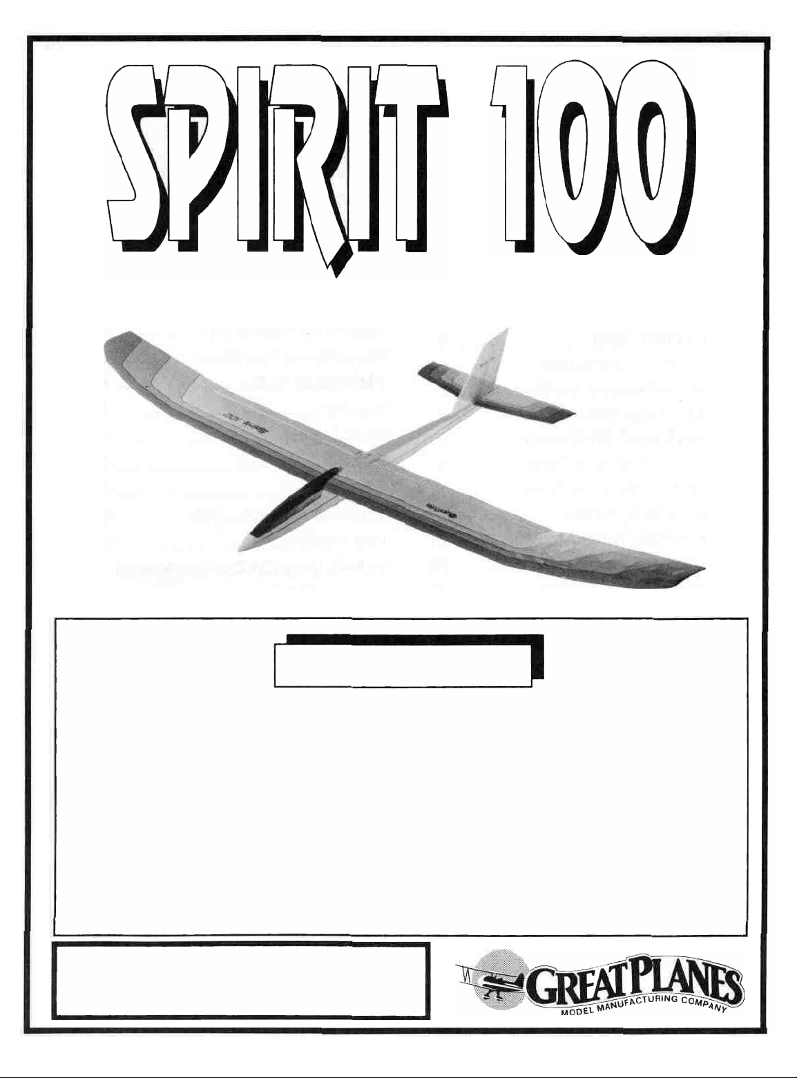
Congratulations! You now own a revolutionary sailplane
kit! A bold statement indeed, but no other sailplane kit has ever
been able to satisfy so many desires. No matter what your skill
level - rank beginner or national soaring champion you will enjoy
this kit from the moment you start construction.
Thank you for purchasing the Great Planes SPIRIT 100
sailplane.
Please inspect all parts carefully before starting to build!
If any parts are missing, broken or defective, or if you have
any questions about building or flying this airplane, please
call
us at
(217)
398-8970
calling for replacement parts, please look up the part numbers and the kit identification number (stamped on the end of
the carton) and have them ready when calling.
PRECAUTIONS
1. You must build the plane according to the plans and in-
structions. Do not alter or modify the model as doing so may
result in an unsafe or un-flyable model In a few cases the plans
and instructions may differ slightly from the photos In those instances you should assume the plans and written instructions
are correct.
2. You must take time to build straight, true and strong.
3. You must use a proper R/C radio that is in first class
condition and meets or exceeds "1991 specs".
4. You must properly install all R/C and other components so
that the model operates properly on the ground and in the air.
and
we'll
be glad to help.
If
you are
6. You must fly the model only with the competent help of a
well experienced R/C pilot if you are not already an experienced
and knowledgeable R/C pilot at this time.
Note: We, as the kit manufacturer, can provide you with
a top quality kit and great instructions, but ultimately the
quality and "flyabilily" of your finished model depends
on how you build it; therefore, we cannot in any way
guarantee the performance of your completed model, and
no representations are expressed or implied as to the
performance or safely of your completed model.
Remember: Take your time and follow directions to end up
with a well-built model that is straight and true.
OTHER ITEMS REQUIRED
0 Radio having at least 2 channels (a third channel is required
for optional spoilers and a 4 channel radio with 5 servos is
required for the advanced wing) A computer radio or comparable radio with mixing capabilities may be used to achieve total
camber control and CROW type mixing
0 Monokote or other covering material (2 rolls)
0 Latex foam rubber padding (1/4" thick)
0 #64 rubber bands
0 Heavy duty hi-start or other launching device
0 BB's or lead shot for balancing
0 Thin but strong thread - 30 (2 - 4lb fishing line works great)
0 Pushrods (Sullivan #503 or equivalent)
0 Hinges
The optional spoilers also require:
0 2 - 36" lengths of 20-30 lb fishing line
0 2 - 36" lengths of 1/8 " plastic tubing
5. You must test the operation of the model before the first and
each successive flight to insure that all equipment is operating,
and you must make certain the model has remained structurally
sound. Be sure to check the nylon clevises often, and replace if
they show signs of wear.
The advanced wing also requires:
0 Thin copper wire or similar (for wrapping flap linkage)
0 2 - 36" servo extensions (or equivalent)
0 2 or 3 -12" servo extensions
3
Page 4
SUPPLIES AND TOOLS NEEDED
0 2 oz Thin CA Adhesive
0 2 07 Medium or Thick CA Adhesive
0 2 5 oz 5-Minute Epoxy
0 Hand or Electric Drill
0 Drill Bits 1/16", 3/32", 1/8", 5/32", 11/64, 13/64" & 1/4"
0 Sealing Iron
0 Heat Gun
0 Soldering Iron (Advanced wing)
0 Razor Saw
0 Hobby Knife, #11 Blades
0 Pliers
0 Screw Drivers
0 T-Pins
0 Assorted Rubber Bands
0 Straightedge
0 Drafting Triangle
0 Masking Tape
0 Cellophane Tape
0 Vinyl Tape
0 Sandpaper (coarse, medium, fine grit)*
0 T-Bar Sanding Block (or similar)
0 Waxed Paper
0 Lightweight Balsa Filler
0 2-56 Tap, Tap Wrench
0 1/4 20 Tap (for bolt on wing option)
0 Dremel Moto Tool or Similar (optional)
*NOTE: On our workbench, we have four 11 T-Bar sanders,
equipped with #50, #80, #100 and #150-gnt sandpaper This
setup is all that is required for almost any sanding task We also
keep some #320-grt wet-or dry sandpaper handy for finish
sanding before covering
COMMON ABBREVIATIONS USED IN THIS
BOOK AND ON THE PLANS:
Elev = Elevator
Fuse = Fuselage
LE = Leading Edge (front)
Lt = Left
Ply = Plywood
Rt = Right
Stab = Stabilizer
TE = Trailing Edge (rear)
" = Inches
Tri = Triangle
TYPES OF WOOD
DECISIONS
YOU MUST
MAKE NOW
WING CONFIGURATION
The SPIRIT 100 kit has two different wing options
The SPORT wing uses the Selig 3010 airfoil, has
optional spoilers and is recommended for novice sailplane
pilots This wing is easy to build, easy to fly and offers
great all-around performance without requiring expensive radio equipment The spoilers arc highly recommended as they make it much easier to land in smaller
spaces or to lose altitude in a safe controlled manner
The ADVANCED wing utilizes the Selig Donovan
7037 airfoil along with flaps and ailerons to provide
incredible thermal soaring performance This wing is
designed to be built with polyhedral which has been
found to work great - enabling the Spirit 100 to thermal
very tightly in low level thermals "Straight wing"
enthusiasts can cut their own polyhedral braces to eliminate the polyhedral if they desire Computer radios and
radios with mixing capabilities can be used to obtain
total camber control (the whole trailing edge will raise or
lower together) and CROW (the ailerons raise about 75
degrees and the flaps drop almost 90 degrees) The SD
7037 airfoil, combined with total camber control, gives
you a sailplane that has an incredible L/D, yet will really
slow down and float when the whole trailing edge is
dropped about 3/32 This feature enables the Spirit 100
to out thermal any other plane in its class
RUBBER BAND OR BOLT-ON WING
Parts are included to build cither a rubber band on
wing or a bolt-on wing held in place with four 1/4-20
nylon bolts
The rubber band on wing is easier to build and will
absorb hard landings better so we recommend it tor less
experienced builders
The bolt on wing offers less drag and more precise at-
tachment It is recommended for the advanced wing and
the serious contest flyer
4
Page 5
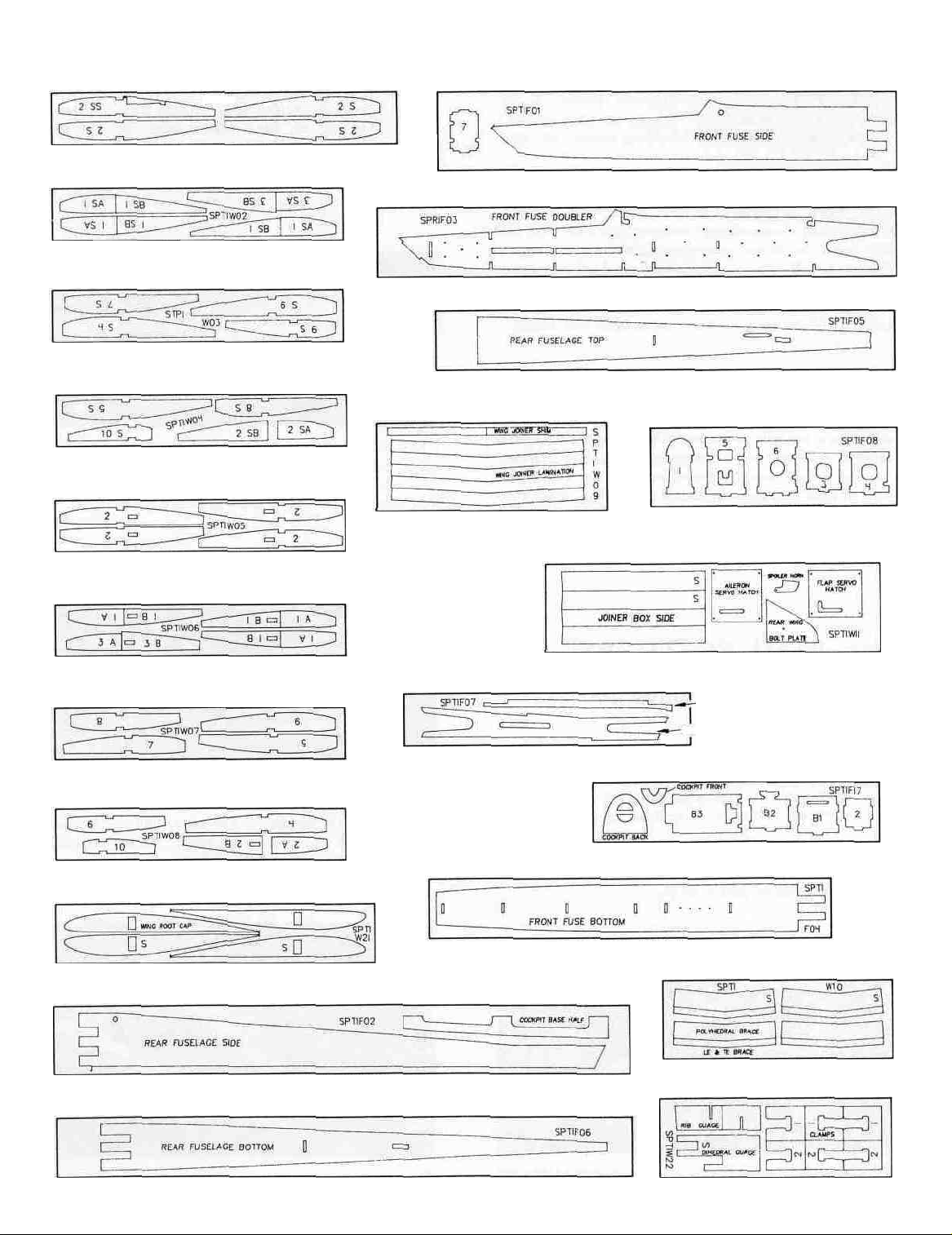
DIE PATTERNS
SPT1W01 4 PER KIT SPT1F01 2 PER KIT
BALSA 1/16- X 2-6/8" X 1/8"
SPT1W02 2 PER KIT
BALSA 1/8" X 2-6/8" X 16"
SPT1W01
SPT1F03
BALSA 1/8" X 4" X 24"
2 PER
KIT
SPT1W03 2 PER KIT
BALSA 1/16" X 2-5/8" X 16"
2
SPT1W04
BALSA 1/16" X 2-6/8" X 16-
SPT1W06
BALSA 1/16" X 2-6/8" X 16"
SPT1W06
BALSA 1/8" X 2-6/8" X 16"
SPT1W07
BALSA 1/16" X 2-6/8" X 16"
SPT1W08 2 PER KIT
PER KIT
4
PER KIT
2
PER
KIT
2
PER KIT
BALSA 3/32- X 3-1/2" X 27"
SPT1F05
SPT1W09 1 PER KIT
PLY 1/16" X 4-1/2" X 12"
SPT1W11 2 PER KIT
SPT1F07
BALSA 3/32" X 2-6/8" X 16"
BALSA 3/32" X 3" X 22"
SPT1F08
PLY 1/16" X 4-1/2" X 18"
2 PER KIT
WING SADDLE TRIPLER
REAR FUSE DOUBLER
SPT1F17
PLY
1/8" X 4- X 12"
1
PER
1
1
PER KIT
PER
KIT
KIT
BALSA 1/16" X 2-6/8" X 16"
SPT1W21 1 PER KIT
BALSA 1/16" X 3" X 18"
SPT1F02
BALSA 1/8" X 3-1/2" X 30"
SPT1F06
BALSA 3/32" X 3" X 30"
SPT1F04
PLY
1/8" X 3" X 21"
2
PER KIT
1
PER
KIT
PLY
1/8" X 3"
SPT1W10
SPT1W22 1 PER KIT
X 16"
1
PER
KIT
2 PER
PLY 1/32" X 3-3/4" X 12"
PLY
1/8" X 4- X 12"
KIT
Page 6
GET READY TO BUILD
NOTE: It will be helpful to build on a piece of "Celotex" or other
semi-soft (and flat) surface, into which you may easily stick pins
to firmly hold down the parts while building, and to avoid warps.
D 1. Unroll the plan sheet. Re-roll the plan inside out and let
it uncurl while you read through this instruction book. This will
help the plan lay flat and you to get acquainted with the building
process. NOTE,: Because there are several options to con-
sider when building the SPIRIT 100, you should read the
instruction book through before building and then go back
and cross off the steps you won't use to build your model.
D 2. Remove all parts from the box. As you do, figure out the
name of each part by comparing it with the plans and the parts list
at the back of this book. Write the part name or size on each piece
to avoid confusion later. Use the die-cut patterns shown on page
5 to identify the die-cut parts and mark them. If any of the die-cut
parts arc difficult to punch out during construction, do not force
them! Instead, first cut around the parts with a hobby knife. After
punching out the die-cut parts, use your T-Bar or sanding block
to lightly sand the edges to remove any die-cutting irregularities.
Tips (SPT1S02) to make the Rudder and Fin Framework.
Notice that the fin leading edge extends down into the fuse so cut
it long enough to extend past the fuse bottom. It will be trimmed
off
flush
with
the
fuse
bottom
the plan and glue the parts together using thin CA glue.
CAUTION: Do not glue the fin to the rudder! Cut the notch
near the back of the fin bottom so it will fit over the stab.
D 3. From the 1/8" x 1/4" x 30" Balsa Tail Rib Sticks (SPT1S04),
cut
the
"ribs"
to
fit
inside
them in place. Cut the gussets from the 1/4" x 3/4" x 24" Balsa
Tail Tips Stick (SPT1S02) and glue them in place.
the
later
rudder
Pin
and
fin
these pieces
framework,
in
place on
and
glue
"TAIL FEATHERS"
BUILD THE FIN AND RUDDER
You'll need the following pans:
SPT1S01 1/4" x 1/2" x 30" Balsa Tail Frame
SPT1S02 1/4" x 3/4" x 24" Balsa Tail Tips
SPT1S04 1/8" x 1/4" x 30" Balsa Tail Ribs
D 1. Tape or pin the plan down to your flat work surface. Tape
a piece of waxed paper over the fin and rudder portion of the plan
(so you don't glue the parts to the plan).
D 4. Remove the fin and rudder assemblies from the plan and
examine them for any open or bad joints. Fill any gaps with
medium or thick CA, then use your sanding block with medium
grit sandpaper to sand both sides of the framework smooth.
D 2. Using the plan as a guide, cut pieces of 1/4" x 1/2" x 30"
Balsa Tail Frame (SPT1S01) and 1/4" x 3/4" x 24" Balsa Tail
D 5. Carefully draw a centerline all around the edges of the
rudder. This will help to maintain symmetry when sanding.
6
Page 7
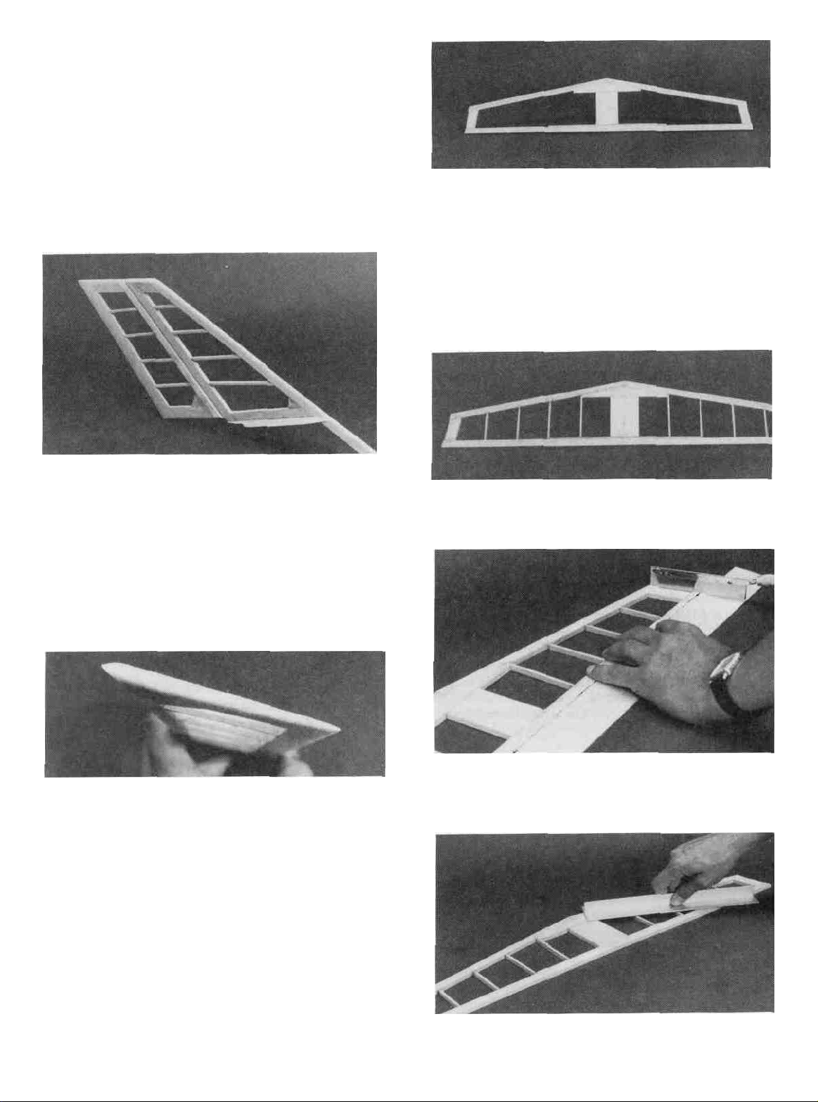
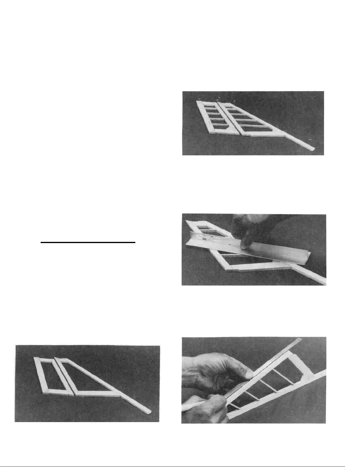
D 6. Using a sanding block and coarse (50 or 80-gnt) sandpaper, sand the leading edge of the rudder to the V-shape as shown
on the plans (a small razor plane works great for initial shaping).
Sand the three remaining edges to a smooth rounded shape.*
Sand the top and the leading edge of the fin to a nice rounded
shape. The leading edge of the fin extends down through the fuse
so you don't need to sand below the edge of the fin bottom.
NOTE: The trailing edge of the FIN must remain square, do
not sand it!
D 1. Tape waxed paper over the stabilizer drawing on the
plan. Cut the leading and trailing edges from the 1/4" x 1/2" x
30" Balsa Tail Frame Stick (SPT1S01). Cut the lips from the
1/4" x 3/4" x 24" Balsa Tail Tips Stick (SPT1S02) and cut the
centerpieces from the 1/4" x 1" x 15" Balsa Stab Center Piece
Stick (SPT 1 S03). Pin these pieces in place over the plan and add
thin CA to each joint.
D 7, Cut two 6" lengths of 1/4" Balsa Triangle(BAL141)and
glue them along the bottom of the fin. The bottom edges of the
triangle should be flush with the bottom of the fin. Sand the
triangle stock to blend with the leading and trailing edges of the
fin. Also, cut or sand the bottom of the triangle stock to match the
notch in the 1/4" balsa fin bottom.
* MAXIMUM PERFORMANCE TIP - Sand both sides of the
rudder to a taper as shown on the plans. This requires a little more
work but will help to reduce drag and thus increase performance
of the sailplane.
D 2. Cut the "ribs" from the 1/8" x 1/4" x 30" Balsa Stick
(SPT 1 S04) and glue them in place.
D 3. Pin or tape the 1/4" Balsa Tapered Elevator (SPT1 S05)
in place behind the stab and use your razor saw to cut the ends off
to match the angle of the stab lips.
BUILD THE STABILIZER AND ELEVATOR
You'll need the following parts:
SPT1S01 1/4" x 1/2" x 30" Balsa Tail Frame
SPT1S02 1/4" x 3/4" x 24" Balsa Tail Tips
SPT1S03 1/4" x 1" x 15" Balsa Stab Center Piece
SFT1S04 1/8" x 1/4" x 30" Balsa Tail Ribs
SPT1S05 1/4" Balsa Tapered Elevator
D 4. Remove the slab from ihc plan and examine it for any
open or bad joints. Fill any gaps with medium or thick CA, then
7
Page 8
use your sanding block with medium grit sandpaper to sand both
sides smooth.
D 5. Carefully draw a centerline all around the edges of the
stab (this will help to maintain symmetry when sanding).
D 6. Tape the elevator to the stab with masking tape and using
a sanding block with coarse (50 or 80-grit) sandpaper, sand the
leading edge of the stab, the stab tips and the elevator tips to a
smooth rounded shape. The tips of the elevator should blend in
nicely with the stab tips. NOTE: The trailing edge of the STAB
must remain square, do not sand it!
D 7. Remove the elevator and draw a center line down its
leading edge. Use your sanding block to sand the same V-shape
as you did on the rudder. The trailing edge should also be sanded
to a smooth rounded shape.
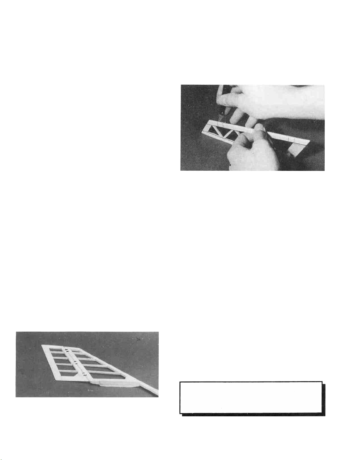
CUT THE HINGE SLOTS (Do not glue)
CAUTION!!!: You must use extreme care when cutting hinge slots with a hobby knife, to avoid cutting
yourself! If the balsa part breaks while you are
pushing on the knife, the blade could go into your hand
before you know it! A good precaution is to wear
leather gloves while performing the following steps.
D 2. Cut the hinge slots on the accurate centerlines which
you previously drew using a hobby knife. (The recommended
hinge slotting technique is listed below).
NOTE: Due to the many types of hinges available and the fact
that everybody seems to have their own favorite, we did not
include hinges in this kit. We can however, highly recommend
the "laminated" type hinges that you install with thin CA, Our
R&D department has thoroughly tested these hinges and found
them to be easy to install and sufficiently strong and durable for
this type of airplane. However, as the kit builder, you are
reminded that you are ultimately responsible for the structural
integrity of your aircraft. If you are not confident using this type
of hinge, please feel free to use your favorite hinge. The hinge
slots for this type of hinge can be cut now or you can wait and cut
them alter the surfaces are covered.
The following instructions explain how to install most hinges.
A. Begin by carefully cutting a very shallow slit at the
hinge location. This first cut is to establish your cut in the
right place, so concentrate on staying on the centerline and
don't cut too deep!
B. Make three or four more cuts in the same line, going
slightly deeper each time. As you make these additional
cuts, work on going straight into the wood. Continue this
process while "wiggling" the knife handle forward and
backward until the blade has reached the proper depth for
the hinge.
C. Trial fit the hinge into the slot. If the hinge is difficult
to push in, re-insert the knife and move it back and forth in
the slot a few times to enlarge the slot.
D 3. Insert the hinges into the slots and trial fit the rudder and
elevator in place on the fin and stab. Do not glue the hinges until
after you have covered the model. Hinge gluing instructions are
included later.
D 1. Lay the rudder and elevators on the plan and mark the
hinge locations. Place the rudder against the fin TE and transfer
the marks over to the fin. Place the elevator against the stab TE
and transfer the marks over to the stab.
IF YOU HAVE DECIDED TO BUILD
THE ADVANCED WING PLEASE
SKIP TO PAGE 20.
8
Page 9
SPORT WING ASSEMBLY
D 1. Tape the plan to your flat work surface and cover the
wing drawing with waxed paper. NOTE: If your work space
is limited, you may cut the wing drawings apart from the rest of
the plans.
D 4. Punch out the two Rib Gauge Pieces (SPT1W22) and
assemble them using CA. Notice that one end of the gauge is
slanted at a 3-1/2 degree angle for positioning the end ribs. The
other 3 ends are perpendicular and can be used to keep parts 90
degrees to the work surface.
D 2. The Shaped Wing Leading Edges (SPT1W14) are fas-
tened together by thin strips of balsa. Separate them by carefully
cutting between the LE'S, with the knife resting against the LE
as a guide. Do not cut vertically at the edge of the LE or it will end
up too narrow. Allow the cut to follow the cross sectional shape
of the LE. Sand away any excess balsa that remains along the
edges using a sanding block with 100-grit sandpaper, but do not
"square off the edges.
TWO WARPED SPARS INSTALLED
THIS WILL WILL RESULT IN A
STRAIGHT WING
TWO WARPED SPARS INSTALLED
THIS WAY WILL RESULT IN A
WARPED WING
BUILD THE INNER WING PANEL
You'll need the following parts:
SPT1W01 1/16" Balsa DC Wing Ribs - W2S, W2SS
SPT1W02 1/8" Balsa DC Wing Ribs - W1S, W3S
SPT1W03 1/16" Balsa DC Wing Ribs - W4S, W6S,
W7S, W9S
SPT1W04 1/16" Balsa DC Wing Ribs - W2SA & B,
W5S,W8S,W10S
SPT1W12 1/8" x 3/8" x 30" Basswood Inner Spars
SPT1W14 Shaped Balsa Leading Edge
SPT1W15 11/32" Balsa Notched Inner TE/Flap
SPT1W20 1/16" x 3" x 30 Balsa Wing Bottom Sheet
SPT1W22 1/8" Ply DC Clamps and Gauges
SPT1W24 1/16" Balsa Shear Web Pack (26)
D 1. Locate all the SPT1W01, SPT1W02, SPT1W03, and
SPT1W04 die-cut rib sheets. Check to make sure you can read
the embossing on each rib. If you can not, use the die patterns on
page 5 to determine the rib #'s and mark the #'s on the ribs.
Carefully punch out all the die-cut balsa wing ribs. Sand the
edges slightly to remove any die-cutting irregularities.
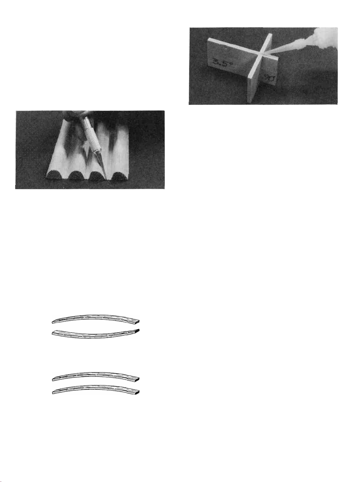
D 3. Before using the 1/8" x 3/8" Basswood Spars, examine
them carefully for possible imperfections. Look for knots, soft
spots, diagonal grain and any other imperfections. If possible,
position each spar so the imperfections are on the outer half of the
wing panel (toward the lip), where they will be least affected by
high stress. If the spars are warped slightly, "balance them out"
by installing the warped spars in opposite directions (see sketch).
NOTE: If you are installing spoilers, cut out the
embossed area on the two W2SS ribs and make sure
you install these ribs in the proper locations. You can
also refer to the plans and mark on each rib where the
spoiler tube will be. Drill a 1/8" hole in the proper
ribs and make sure they get installed in the correct
places.
9
Page 10
D 2. Son through the three 1/16" x 3" x 30" Balsa Wing
Sheeting (SPT1W20) and pick out the two sheets that most
closely match each other in weight and grain. These will be the
bottom sheeting for the inner wing panels. Check to make sure
the two "bottom" sheets have at least one straight edge. If' not,
use a metal straight edge to cut as little as possible off of one long
edge to make it straight.
NOTE: Follow the steps with two check boxes
to build the RIGHT wing panel, then repeat
these steps to build the LEFT wing panel.
DD 6. Place six W2S and two W2SS ribs (SPT1W01) on
the spar in their approximate positions, work the ribs into the
notches on the
The W2SS ribs should be installed where the spoiler will be
located.
D D 7. Make sure the ribs are properly positioned accord-
ing to the plans and glue them to the spar using med. or thick CA.
Do not purposely glue the ribs to the sheeting yet. Use the
square end of the rib gauge to keep the ribs perpendicular to the
work surface. Hold the TE and the ribs flat against the plan. With
the ribs inserted fully into the notches, add a drop of thin CA to
each joint.
trailing
edge
but
do not glue anythmg yet. NOTE:
D D 3. Glue one of the "Inner Bottom" wing sheets to the
edge
of
an
1/8" x3/8"x 30" Basswood Inner Spar
using the following procedure. With the spar in position on the
plan, hold the straight edge of the bottom wing sheet up against
it. Starling about 9 inches from the "root" end (where the second
W2S rib will be positioned), add thin CA along the joint. Be sure
to hold both the spar and the bottom wing sheet flat against the
work surface while the glue cures. Glue a 5" -6" section at a time
until you get within 4" of the other end (where the last W2S rib
will be installed). Do not glue the two ends yet as some of the
sheeting will be cut away later.
D D 4. Align the bottom spar/wing sheet assembly with the
"Inner Panel" drawing on the plan and pin it in place. This
assembly will be a little long but just center it over the inner panel
drawing.
D D 5. Pin one of the 11/32" Balsa Inner Trailing Edges
(SPT1W15) to the plan, lining up the notches in the TE wilh the
notches on the plan. Use a couple of W2S ribs to correctly space
the TE behind the spar. If the notches are off a little from the plan
it is due to the moisture content of the air. Just line up the root end
of the TE and space the ribs according to the TE, not the plans.
(SPT1W12)
D D 8. Trial fit the Top 1/8" x 3/8" x 30" Basswood Inner
Spar (SPT 1 W 12) into the notches in the ribs by carefully pushing
the spar completely down into the notches. Make sure the top spar
is lined up lengthwise with the bottom spar. Remove the spar and
apply med. or thick CA to the notches. Replace the spar and make
sure the spar is level with the front half of the rib so the sheeting
will lie flat on the spar.
D D 9. Position a 1/8" x 3/8" x 23-1/2" Basswood Outer
Spar (SPT1W 13) under the front edge of the leading edge sheet
to hold it up against the front of the rib. Use weights or pins near
the spar to hold the panel flat on the work surface during this step.
Apply Am CA to glue the sheeting to the ribs. The outer spar is
10
Page 11

shorter than the panel so you will have to do approx half the ribs
then move the spar down to do the rest of the ribs
W2S ribs and note that it is wider than the front of the rib This
is because the 1/16 balsa leading edge top sheeting will be added
later Align the lower surface of the leading edge with the bottom
of the lower LE sheet and glue it in place with a drop of thin CA
Align the other end of the leading edge with the bottom of the
opposite end W2S and glue it with a drop of thin CA Go down
the line and glue the remaining ribs to the leading edge, one at a
time, so you can make sure they are aligned Make sure the LE
sheeting is flush with the bottom of the LE and add CA between
the ribs Do not glue the sheeting to the LE past the last W2S ribs
yet.
IMPORTANT - MAKE SURE THE WING
PANEL REMAINS ABSOLUTELY FLAT
DURING THE NEXT STEP!
D D 10 Unpin the wing panel from the work surface and
hold a metal straight edge against the front of the ribs Allow the
panel to tip up so the front edge of the sheeting is flat on the work
surface and use an Xacto knife to carefully cut the sheeting off
flush with the from edge of the ribs Use a sanding block to
remove any "bumps" but be careful not to sand any dips into the
sheeting or sand the ribs
D D 11 Position a Pre-Shaped Balsa Leading Edge
(SPT 1 W 14) in place against the front of the ribs NOTE: 1 these
leading edges are NOT symmetrical. Refer to one of the section
views on the plans to determine which way they should be
installed Carefully hold the leading edge against one of the end
DD 12 Locate the 1/16" Balsa Shear Webs (SPT1W24)
Trial fit one of the webs in place between the first and second
W2S ribs Glue the shear web in place on the back of the spars
using med or thick CA The web should be pressed down against
11
Page 12
the work surface and tightly against the spars. It is important to
do a good job of gluing these in place as they are responsible for
most of the wing's strength. Also glue a shear web to the front of
the spars. Because of the 1/16" bottom sheeting, the front shear
webs will extend above the top spar, but just trim them off after
you have installed all the webs. C-1 and C-2 Clamps (SFT1W22)
can be used to help hold the webs in place while the glue cures.
Install the remaining balsa shear webs. They continue on both the
front and the back of the spar all the way to the last W2S Rib.
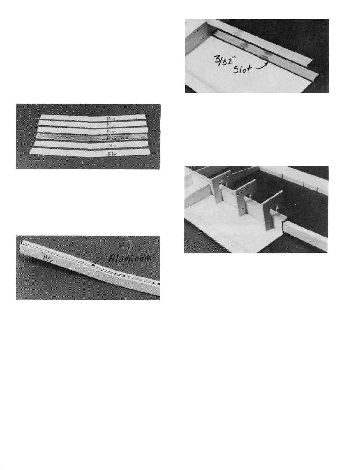
DD 13. Punch out the five 1/16" Ply Wing Joiner Lamina-
tions (SPT1W09) and lightly sand the edges to remove any rough
spots. Locate the 1/16" Aluminum Wing Joiner Blade
(ALUM008). Clean the aluminum joiner with alcohol to remove
any oily residue and sand each side with coarse sandpaper to
scratch the surface and help the glue stick.
the panel and mark approximately 1/32" in front of it. Now cut
along this line and the spar to remove a 3/32" wide strip of wood
from the root of the panel to the first W2S rib. Scrape off any glue
or balsa wood thai may still be on the spar with the back edge of
an Xacto knife. IMPORTANT - Be sure to get the edge of the
spar "clean" as a good glue joint between the spar and the joiner
box side is very important.
I—II—I
14.
Use either epoxy or med.
the 1/16" ply laminations to the 1/16" aluminum blade. Apply as
much pressure (clamps, clothespins, weights, etc.) as possible
while the glue is curing and be sure to accurately line up the two
pieces. Glue two more 1/16" ply laminations to each side of the
now 1/8" thick joiner using the same procedure.
DD 15. Sand the top edge of the laminated joiner flat and
glue the Die-Cut 1/16" Ply Joiner Shim (SPT 1W09) in place on
top of the joiner. Sand the edges of the finished "wing joiner" to
remove any glue globs and to round off the comers.
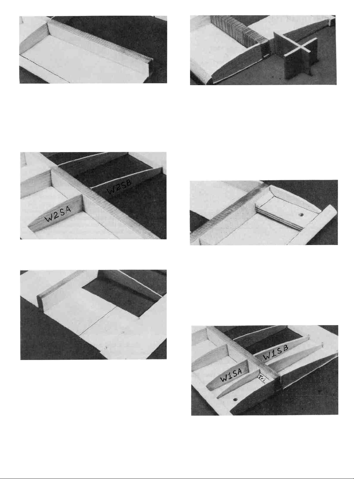
DD 16. Locale two of the 1/16" Ply Joiner Box Sides
(SPT 1 W 11) that have an "S" embossed on them. Hold one of the
sides in place on the front of the spars at the "root" (inner) end of
or
thick CA to
glue
one of
DD 17. Test fit the joiner box sides in place. One side
should be installed on the front of the spars and the other on the
back. Notice that one end of the side is slanted at a 3-1/2 degree
angle. This end must be at the wing centerline. The "long" edge
of the side should be at the bottom. Use the C1 Clamps
(SPT 1 W22) to hold the sides in place and test tit the wing joiner
into the box formed. This "box" will be referred to as the "joiner
box". The spars should fit snugly down on the wing joiner, but
make sure the joiner is not holding the spars above their normal
position. If it is remove the joiner and sand it until it fits correctly.
DD 18. Remove the clamps and the joiner and apply a bead
of epoxy along the spar edges. Install the joiner box sides and
hold them in place with the C1 clamps. A good glue joint is
important here but be careful not to get any excess glue inside the
box formed by these sides. Insert the joiner into the box and then
remove it a couple of times to scrape any excess glue out of the
box. Wipe any glue off the joiner before it cures.
DD 19. Sand the edges of the joiner sides to remove any
sharp comers or glue globs. Wrap the entire joiner box with a
strong thread (2 - 4 lb. fishing line works well). The thread should
12
Page 13
be tightly wrapped and closely spaced near the root end but it can
be spaced farther apart as you get closer to the W2S rib Do not
allow the thread to overlap or it will build up in thickness and the
top sheeting will not seat properly on the spar When finished
wrapping, soak the entire thread with CA HINT - It will take at
least 15 feet
of
thread to properly wrap each joiner box
these
you should drill 1/8" holes in the remaining W1 SB ribs for the
tubing before gluing them in place.
D D 23 Position the 1/4" xl-l/8"x 2-7/8" Ply Front Wing
Bolt Plate (SPT1W27) next to the template on the plan Use the
measurements given to mark where to drill the hole Drill a
13/64 hole at the mark Notice that the hole is off-center
SKIP
BAND ON WING.
ribs
into
THIS
STEP IF YOU
place
NOTE:
If
you are going to
ARE
BUILDING A RUBBER
install
spoilers,
D D 20 With the wing panel over the plans for reference,
glue W2SA and the W2SB (SPT1W04) in place
DD 21. Locate the "odd" (see
Balsa Sheet (SPRTW20) and cut off three pieces 3" long Slide
one of the sheets in place behind the joiner box and glue it in place
with med or thick CA Cut another piece to fit between the first
sheet and the TE and glue it in place Save the remaining pieces
for the other wing panel
D D 22 Punch out three W1SA ribs and three W1SB ribs
(SPRTW01) and test fit the end W1SA and W1SB ribs into
position A little sanding may be necessary to make them fit
properly They should be tilted in (towards the tip) at the top using
the slanted end of the rib gauge to achieve the correct angle Glue
p10,
step 2) 1/16" x
3" x 30"
D D 24 Test fit the front wing bolt plate in place against the
W1SA rib It should be centered up and down on the LE and it
should be parallel to the work surface, with the hole off-center
towards the root of the wing Sand it if necessary to achieve a
good fit between the LE and the joiner box When satisfied with
the fit, securely glue it in place with either med or thick CA or
epoxy Add 1/4" balsa triangle along the spar and a Fillet of glue
along the LE.
D D 25 Glue the remaining W1SA and W 1 SB ribs in place
The second W1SA should be against the wing bolt plate Glue the
bottom sheeting to each of these ribs and cut off any excess
sheeting, spars, LE, or TE flush with the end W1S rib
13
Page 14
BUILD THE OUTER WING PANEL
You'll need the following parts:
SPT1W03 1/16" Balsa DC Wing Ribs - W4S,
W6S, W7S, W9S
SPT1W04 1/16" Balsa DC Wing Ribs - W2SA & B,
W5S,W8S,W10S
SPT1W13 1/8" x 3/8" x 23-1/2" Basswood Outer Spars
SPT1W14 Shaped Balsa Leading Edge
SPT1W16 11/32" Balsa Notched Outer Trailing Edge
SPT1W23 7/8" Shaped Balsa Wing Tip Block
D D 1. Lay one of the Balsa Outer Trailing Edges
(SPT1W16) in place over the plan. Align the notches in the
trailing edge with the notches on the plans and pin it in position.
NOTE: The excess TE will later be cut off and used to
make the spoiler.
T-Pins
Work Surface
D D 2. "Cross pin" one of the 1/8" x 3/8" x 23-1/2" Bass-
wood Outer Spars (SPT1W13) in place.
Spar
into the notches until it is flush with the top of the ribs. Remove
the spar and apply med or thick CA to the notches. Replace the
spar and allow the glue to cure.
D D 5. Lay a Pre-Shaped Balsa Leading Edge (SPT 1 W! 4)
over the LEADING EDGE TEMPLATE on the plans. Use this
drawing as a reference to cut the relief notches. It is a good idea
to cut the leading edge approximately 1/4" longer on both
ends to be on the safe side. It can be trimmed to the correct Iength
after it is installed. The relief notches do not need to go all the way
through the leading edge but should go within 1/8" of doing so.
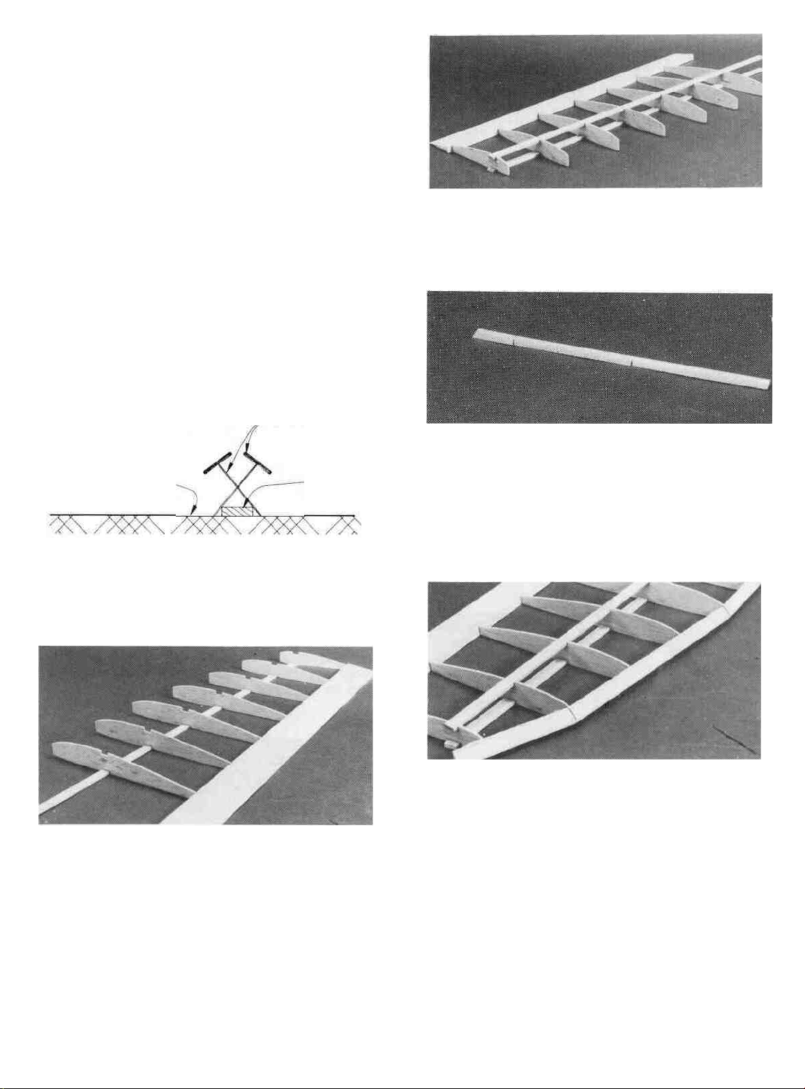
D D 3. Locate the 1/16" (W4S - W10S) Outer Panel Ribs
(SPT1W03 & SPT1W04). Glue the ribs in place with med. or
thick CA at the spar Joint and a drop of thin CA at the trailing edge
joint. Use the rib gauge to keep the ribs perpendicular to the work
surface.
D D 4. Trial fit the Top 1/8" x 3/8" x 23-1/2" Basswood
Outer Spar (SPT1W13) in place by carefully pressing the spar
D D 16. Carefully bend the leading edge to the angle shown
on the plans and position it against the ribs. The bends should be
at ribs W6S and W9S. Align the leading edge with the ribs and
glue it in place, just as you did for the inner panel, except start at
ribs W6S and W9S. Add med. or thick CA to each relief notch
to fill in any gaps.
D D 7 With the panel flat on the work surface, install me
1/16" Shear Webs (SPT 1W24), following the same procedure as
you did on the inner panel. The webs will extend past the top spar
14
Page 15
but just trim them flush with the spars and sand the edges round
so they do not make a ridge when the covering is applied.
DD 8. Cut and sand the trailing edge, spars and leading edge
flush with rib W10S. Set the panel down on the plan and cut the
root end of the spars, LE and TE to the correct length. Save the
scrap piece of TE to use as a spoiler if needed.
and the above photos to show you the recommended shape.
CAUTION - Do not sand the TE of the tip to a very thin edge
or it will get damaged very easily. It is best to leave it 1/32"
-1/16" thick.
D D 11. Apply several drops of thin CA to the rear portion of
the balsa wing tip. Allow the glue to soak into the wood and cure.
The glue will help harden the wood and protect it from damage.
DD 9. Glue the 7/8" Balsa Wing Tip Blocks (SPTlW23) to
W10S with med. or thick CA. Line up the front of the tip block
with the front of the LE and allow the excess to extend past the TE.
DD 10. Carve and sand the wing tip to blend in with rib W1OS
and the TE. Be careful not to change the shape of W10S while
sanding the tip. There are three section views on the left wing plan
JOIN THE INNER AND OUTER
WING PANELS
D D 1. Prop up the outer wing panel 3-1/2" (from the work
surface to the bottom of the spar at W10S), using the top notch
in the Dihedral Gauge (SPT1W22) between ribs W9S and
W10S. Move the dihedral gauge if necessary to get the correct
15
Page 16
measurement at rib W10S. Use a sanding block to carefully sand
the leading edge, spars and trailing edge to achieve vertical
surfaces on each. Check your progress by occasionally setting
the panel on the plans to make sure you are not sanding any
"sweep" (forward or backward tilt) into the wing. HINT- Set the
panel on an "elevated" building surface an inch or so above the
work surface and use the edge of the elevated surface to hold the
sanding block perpendicular to the work surface as shown in the
photo.
D D 2. With the inner panel flat on the work surface, sand
the leading edge, spars and trailing edge so they are all even and
of the correct length.
D D 3. Test fit the inner and outer panels together over the
plan to make sure the leading edges, spars, and trailing edges all
meet up nicely when the tip panel is blocked up the required
3-1/2" (at the bottom of rib W10S) with the dihedral gauge. Sand
any ends if needed to make everything fit well.
both sides of the spars. Use the die-cut C2 clamps (SPT1W22)
to hold everything in place. Wipe off any excess glue before it
cures.
D D 4. With the dihedral gauge in place, Apply med. or thick
CA or epoxy to the leading edge, trailing edge and spar joints to
"tack glue" the two panels together. Hold everything in place
until the glue has cured.
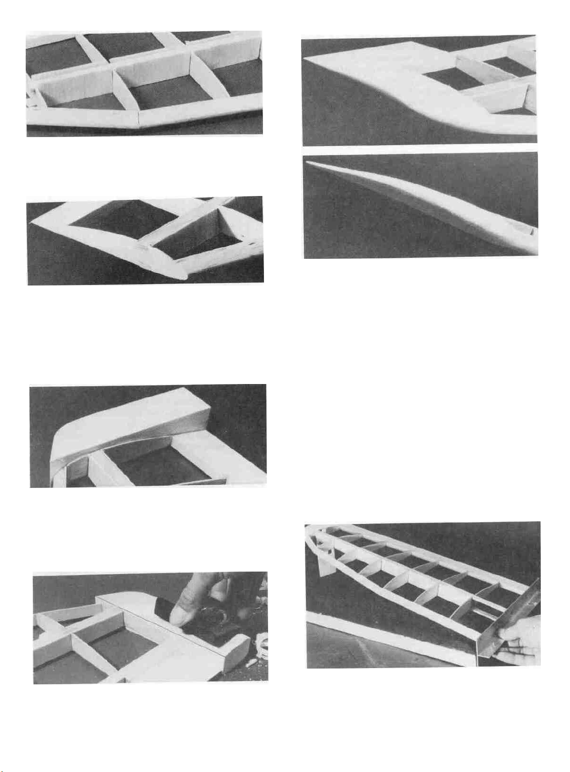
D D 5. Cut the balsa bottom sheeting away (1/32") from the
front of the inner panel spar to clear the polyhedral brace. The cut
should start at the last W2S rib and continue to the end of the spar.
Punch out two of the 1/32" Die-Cut Ply Polyhedral Braces
(SPT1W10) with an "S" embossed on them and test fit them in
place against the front and back of the spars. Sand them if needed
to achieve a good fit.
D D 7. Locate the two 1/32" Die-Cut Ply Leading and
Trailing Edge Braces (SPT1W10) that were next to the polyhedral braces you used earlier. Test fit them in place and sand them
if needed to make them fit between the rib W2S and W4S. The
LE brace should be at least 1/16" below the top of the LE to allow
for the 1/16" top sheeting, which will be added later. Glue them
in place with med. or thick CA. If the TE brace extends above or
below the surface of the TE, sand it flush.
D D 8. Install ribs W3SA and W3SB (SPT1W02) between
the inner and outer panels using med. or thick CA. A little sanding
may be necessary to achieve a good fit. Use the rib gauge to tilt
the ribs to the proper angle.
D D 6. When satisfied with the fit, apply a generous bead of
epoxy or med. or thick CA to the spars and install the braces on
D D 9. Drill a 13/64" hole down through the hole in the front
wing bolt plate and through the 1/16" bottom sheeting. Lightly
16
Page 17

sand the tops of the inner panel ribs and the spar to remove any
glue globs or uneven places.
DD
10
Check to make sure one edge of the l/16" x3-l/2"
30" Balsa Top Leading Edge Sheeting (SPT1W25) is straight,
and if not, cut it straight using a metal straight edge.
can put weights on the strip of wood if needed CAUTION • It
is important to keep the wing flat and warp-free during this
step!
x
D D 13 Apply thin CA between the pieces of masking tape
along the leading edge Remove the tape and apply thin CA
where the tape was
D D 14 Drill a 13/64" hole up through the hole in the wing
bolt plate
the top sheeting to approx 5/8 diameter so the head of the wing
bolt will pass through
and
through
the
1/16"
top sheeting
Enlarge
the hole
in
D D 11. Position the 1/16" sheeting in place so the straight
edge is against the leading edge and one end is covering W3SA
Apply several strips of masking tape to hold it in place and act as
a hinge lor the gluing process Press the sheeting onto the ribs and
trim it flush with the back edge of the spar using a modeling knife
and straight edge Be careful not to cut into the thread when
cutting near the root of the panel Save the scrap of sheeting for
later
D D 12. Lift the sheeting up and apply a bead of med or thick
CA along the top of each rib and along the top spar Quickly press
the sheeting down into place and hold it until the glue has cured
Keep the sheeting pressed against the ribs and the spar while the
glue cures A straight strip of wood the length of the panel, can
be a big help when trying to hold the sheeting down evenly You
IF YOU ARE NOT INSTALLING
SPOILERS, SKIP TO STEP 23
D D 15 Cut one 8" long spoiler from the un-notched scrap
end of each Outer Panel Trailing Edge (SPRTW12) Cut four
pieces of 3/16 x 1/4 balsa 1-1/2 long and two pieces 1" long
from the 3/16" x 1/4" x 24" Balsa Spoiler Bay Frame (SPT1W26)
Also cut two
1/16" sheeting.
D D 16 Glue the 1/16" x 1/8" x 8-1/16" piece of balsa to the
back edge of the sheeting, between the W2S ribs as shown in the
pieces
of
1/16" x 1/8"
Balsa
8-1/16" long from scrap
17
Page 18

photo. It should be flush with the top of the leading edge sheeting.
DD 17. Cut a piece of 3/16" x 1/4" Balsa (SPT1W26) to fit
between the W2S ribs (approx. 8-1/16" long). Glue the strip of
balsa in the notch on the W2SS ribs. It should be glued to the W2S
ribs at its ends and be flush with the TOP of the ribs.
to hold the spoiler about 1/32" above the surface of the wing and
then sand the spoiler to match the contour of the wing surface.
D D 20. If you are using the spoiler setup shown on the plans,
the spoiler tube should exit the bottom of the wing just behind the
wing joiner box, between the first and second W1BS ribs. Drill
a 1/8" hole in the bottom center section sheeting for the tube.
D D 18. Test fit the spoiler in the "bay" and sand it if necessary to achieve a 1/32" gap around the sides and trailing edge. Use
a strip of masking tape to temporarily hinge the spoiler along the
1/16" x 1/8" strip of balsa.
D D 19. With the spoiler in place, glue the 3/16" x 1/4" x 1-
1/2" pieces of balsa to the W2S ribs. These are the spoiler rests
and should be positioned so they hold the spoiler flush with the
top
surface
of
the
wing.
NOTE:
sit flush with the top of the wing or it will disrupt the airflow
over the wing. If you desire, you can position the 1-1/2" pieces
It
is
important that the spoiler
DD 21. Slide a 1/8" diameter nylon tubing (inner pushrod
tube or antenna tube, not included) through the holes in the ribs.
Cut a 1/8" wide, 1/8" deep notch in the middle of the 3/16" x
1/4" x 1" piece of balsa and glue it to the bottom of the 3/16" x
1/4" x 8-1/16" piece, trapping the end of the spoiler tube in the
notch as shown in the photo. The nylon lube should extend past
the LE approximately 4" to help get the spoiler string to the servos
in the fuse. Glue the tube to each rib and the bottom sheeting
using med. or thick CA.
18
Page 19

D D 22. Drill a 1/16" hole in each 1/16" Die-Cut Ply Spoiler
Horn (SPT1W11) at the indentation. Cut a 1/16" wide slot in the
spoiler for the spoiler horn using a razor saw (a hack saw blade
will also work fine), and glue the horn in place. It should be flush
with the top surface of the spoiler as shown on the plans. This
completes the assembly of the spoilers until after the wing is
covered.
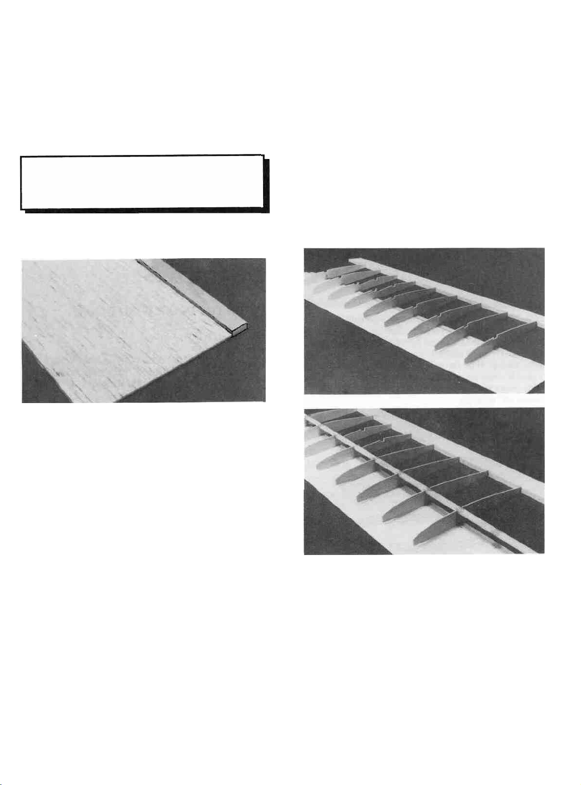
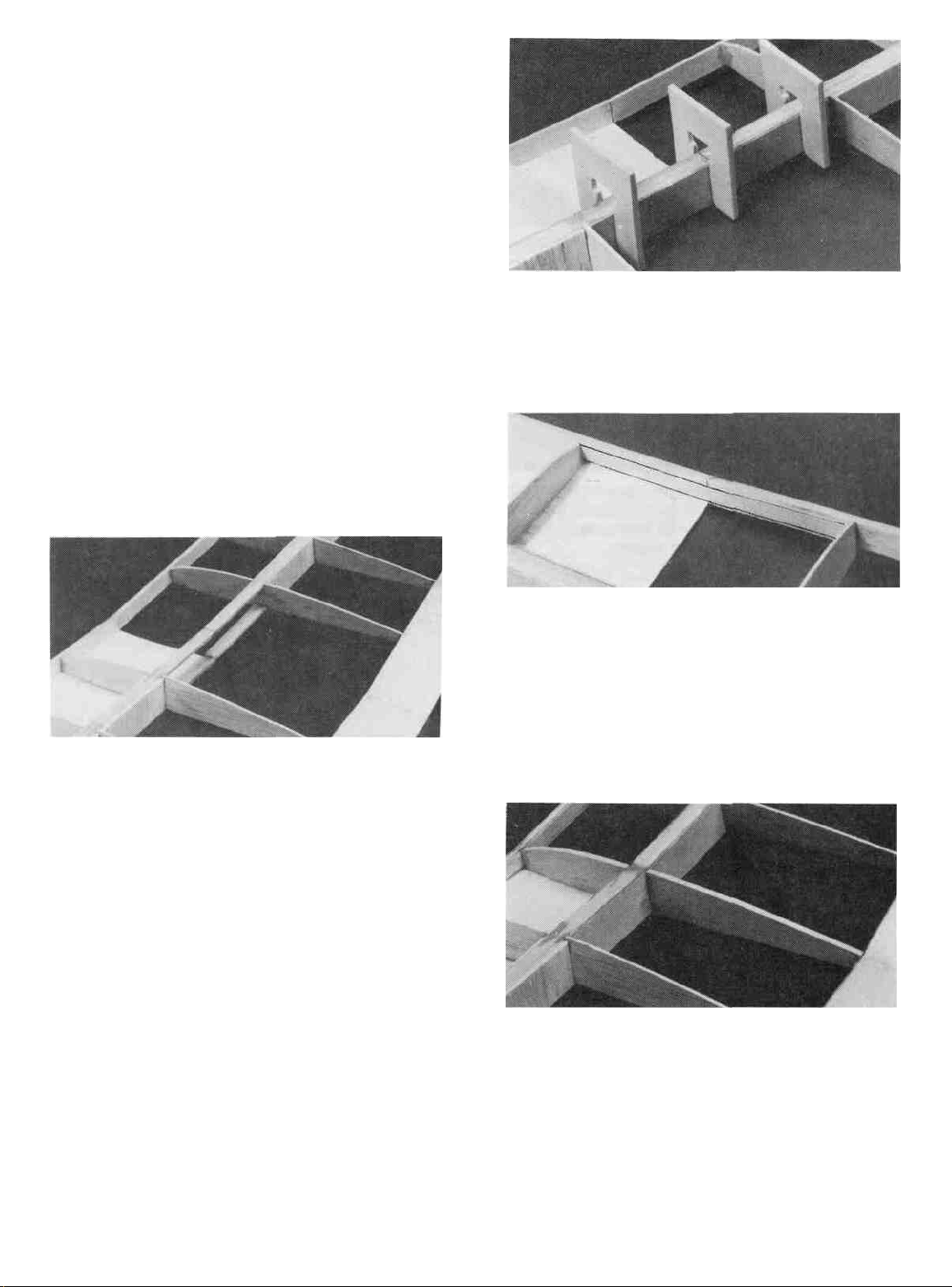
D D 24. Cut the sheeting off at an angle from the front of
W2BS to approx. 1/4" out
plans. Sand the sheeting flush with the W1BS rib at the wing root.
(The photo for this step is at the bottom of the last column)
D 25. Now go back to page 9 and assemble the other wing
panel.
D 26. Trial fit the two wing halves together using the wing
joiner. Sand the root of each panel, if needed, to achieve a nice
close joint between the two wings. If there are large gaps, fill
them with scrap balsa or filler. Glue the 1/16" Balsa Wing Root
Caps with an "S" (SPT1W21) to the root of each panel.
from
the rear
of
W1BS as
shown
on the
DD
23.
Cut a 4" and a 5" piece of l/16" balsa sheeting to sheet
the top inboard center section out to rib W2BS, as shown in the
photo. Med. or thick CA should be used for this step. Glue the
5" piece near the spars, and cut the 4" piece to fit between the first
piece and the trailing edge.
D 27. Make sure you can see the pinpoint punch on the top of
a
1/16"
Ply
Rear Wing Bolt Plate (SPT1W11).
through the punch mark. Sand the "outside" top edges of the rear
wing bolt plate to a taper as shown in the photo. Glue each one
in place so the rear is flush with the back of the TE and the side
is flush with the root cap. Sand the inside edge to match the
dihedral angle of the root cap.
D 28. This completes the SPORT wing assembly so skip to
page 34 to FUSELAGE ASSEMBLY.
If
19
not,
stick
a pin
Page 20

ADVANCED WING
ASSEMBLY
D 1. Tape the plan to your flat work surface and cover the
wing drawing with waxed paper. NOTE: If your work space
is limited, you may cut the wing drawings apart from the rest of
the plans.
D 4. Punch out the two Rib Gauge Pieces (SPT1W22) and
assemble them using CA. Notice that one end of the gauge is
slanted at a 3-1/2 degree angle for positioning the end ribs. The
other 3 ends are perpendicular and can be used to keep parts 90
degrees to the work surface.
BUILD THE INNER WING PANEL
You'll need the following parts:
D 2. The Shaped Wing Leading Edges (SPTlW14) are fastened together.
Cut between the LE'S, with the knife resting against the LE
as a guide. Do not cut vertically at the edge of the LE or it will end
up to narrow. Allow the cut to follow the cross sectional shape
of the LE. Sand away any excess balsa that remains along the
edges using a sanding block with 100-grit sandpaper, but do not
"square off" the edges.
TWO WARPED SPARS INSTALLED
THIS WAY WILL RESULT IN A
STRAIGHT WING
TWO WARPED SPARS INSTALLED
THIS WAY WILL RESULT IN A
WARPED WING
D 3. Before using the 1/8" x 3/8" Basswood Spars, exam-
ine them carefully for possible imperfections. Look for knots,
soft spots, diagonal grain and any other imperfections. If possible, position each spar so the imperfections are on the outer half
of the wing panel (toward the tip), where they will be least
affected by high stress. If the spars are warped slightly, "balance
them out" by installing the warped spars in opposite directions
(see sketch).
SPT1W05 1/16" Balsa DC Wing Ribs - W2
SPT1W06 1/8" Balsa DC Wing Ribs - W1, W3
SPT1W07 1/16" Balsa DC Wing Ribs - W4, W6,
W7,W9
SPT1W08 1/16" Balsa DC Wing Ribs - W2A & B,
W5,W8,W10
SPT1W12 1/8" x 3/8" x 30" Basswood Inner Spars
SPT1W14 Shaped Balsa Leading Edge
SPT1W18 3/8" Balsa Notched Inner Sub TE
SPT1W20 1/16" x 3" x 30" Balsa Wing Bottom Sheet
SPT1W22 1/8" Ply DC Clamps and Gauges
SPT1W24 1/16" Balsa Shear Web Pack (26)
D 1. Locate all the SPT1W05, SPT1W06, SPT1W07 and
SPT1W08 die-cut rib sheets. Check to make sure you can read
the embossing on each rib. If you can not, use the die patterns on
page 5 to determine the rib #'s and mark the #'s on the ribs.
Carefully punch out all the die-cut 1/16" Balsa Wing Ribs. Sand
the edges slightly to remove any die-cutting irregularities.
D 2. Son through the three 1/16" x 3" x 30" Balsa Wing
Bottom Sheeting (SPT1W20) and pick out the two sheets that
most closely match each other in weight and grain. These two
sheets will be the bottom sheeting for the inner panels. Check to
make sure the two "bottom" sheets have at least one straight
edge. If not, use a metal straight edge to cut as little as possible
off one long edge to make it straight.
NOTE: Follow the steps with two check boxes
to build the RIGHT wing panel, then repeat
these steps to build the LEFT wing panel.
20
Page 21

D D 3. Glue one of the "Inner Bottom" wing sheets to the
edge of a 1/8" x 3/8" x 30" Basswood Inner Spar (SPT1W12)
using the following procedure. With the spar in position on the
plan, hold the straight edge of the bottom wing sheet up against
it. Starting about 9 inches from the "root" end (where the first W2
rib will be positioned), add thin CA along the joint. Be sure to
hold both the spar and the bottom wing sheet flat against the work
surface while the glue cures. Glue a 5" - 6" section at a time until
you get within 4" of the other end (where the last W2 rib will be
installed). Do not glue the two ends yet as some of the sheeting
will be cut away later.
D D 4. Align the bottom spar/wing sheet assembly with the
"Inner Panel" drawing on the wing plan and pin it in place. This
assembly will be a little long but just center it over the inner panel
drawing.
not purposely glue the ribs to the sheeting yet. Use the square
end of the rib gauge to keep the ribs perpendicular to the work
surface. Hold the sub TE and the first W2 rib flat against the plan
and with the rib inserted fully into the notch, add a drop of thin CA
to the joint. Do the same to the rest of the W2 ribs.
D D 8. Trial fit the Top 1/8" x 3/8" x 30" Basswood Inner
Spar (SPT1W12) into the notches in the ribs by carefully pushing
the spar completely down into the notches. Make sure the top
spar is lined up lengthwise with the bottom spar. Remove the spar
and apply med. or thick CA to the notches. Replace the spar and
make sure the spar is level with the front half of the rib so the
sheeting will lie flat on the spar.
D D 5. Pin one of the Notched Balsa Inner Sub Trailing
edges (SPTW18)
to the plan,
lining
up the notches
in
the sub TE
with the notches on the plan. Use a couple of W2 ribs to correctly
space the sub TE behind the spar. If the notches are off a little
from the plan it is due to the moisture content of the air. Just line
up the root end of the sub TE and space the ribs according to the
sub TE, not the plans.
DD 6. Place the eight W-2 ribs (SPT1W05) on the spar in
their approximate positions. Work the ribs into the notches on the
trailing edge but do not glue anything yet.
DD 7. Make sure the ribs are properly positioned according
to the plans and glue them to the spar using med. or thick CA. Do
DD 9. Position a 1/8" x 3/8" x 23-1/2" Basswood Outer
Spar (SPT1W13) under the front edge of the leading edge sheet
to hold it up against the front of the rib. Use weights or pins near
the spar to hold the panel flat on the work surface during this step.
Apply thin CA to glue the sheeting to the ribs. The outer spar is
shorter than the panel so you will have to do approx. half the ribs
then move the spar down to do the rest of the ribs.
D D 10. Unpin the wing panel from the work surface and hold
a metal straight edge against the front of the ribs. Allow the panel
to tip up so the front edge of the sheeting is flat on the work surface
and use an Xacto knife to carefully cut the sheeting off flush with
the front edge of the ribs. Use a sanding block to remove any
21
Page 22

IMPORTANT - MAKE SURE THE WING
PANEL REMAINS ABSOLUTELY FLAT
DURING THE NEXT STEP!
"bumps" but be careful not to sand any dips into the sheeting or
sand the ribs
D D 11 Position a Pre-Shaped Leading Edge (SPT1W14)
in
place against the front
edges are NOT symmetrical. Refer to one of the section views
on the plans to determine which way they should be installed
Carefully hold the leading edge against one of the end W2 ribs
and note it is wider than the front of the rib This is because the
1/16 balsa leading edge top sheeting will be added later Align
the lower surface of the leading edge with the bottom of the lower
LE sheet and glue it in place with a drop of thin CA Align the
other end of the leading edge with the bottom of the opposite end
W2 and glue it with a drop of thin CA Go down the line and glue
the remaining ribs to the leading edge, one at a lime, so you can
make sure they are aligned Make sure the LE sheeting is flush
with the bottom of the LE and add CA between the ribs Do not
glue the sheeting to the LE past the last W2 ribs yet
of
the
ribs
NOTE:
These leading
DD 12 Locate the 1/16" Balsa Shear Webs (SPT1W24)
Trial fit one of the webs in place between the second and third W2
ribs Glue the shear web in place on the back of the spars using
med or thick CA The web should be pressed down against the
work surface and tightly against the spars It is important to do
a good job of gluing these in place as they are responsible for most
of the wing's strength Also, glue a shear web to the front of the
spars
Because
will extend up past the top spar, but they will be trimmed off later
C-l and C-2 Clamps (SPT1W22) can be used to help hold the
webs in place while the glue cures Install the remaining balsa
shear webs They continue on both the front and the back of the
spar, all the way to the last W2 Rib
DD 13 Punch out the five 1/16" PLY Wing Joiner Lamina-
tions (SPT1W09) and lightly sand the edges to remove any rough
spots Locate the 1/16" Aluminum Wing Joiner Blade
(ALUM008) Clean the alummum joiner
any oily residue and sand each side with coarse sandpaper to
scratch the surface and help the glue stick
of
the
1/16
bottom sheeting, the
front
shear webs
with
alcohol to remove
DD 14 Use either epoxy or med or thick CA to glue one of the
1/16" ply laminations to the 1/16" aluminum lamination Apply
22
Page 23

as much pressure (clamps, clothespins, weights, etc ) as possible
while the glue is curing and be sure to accurately line up the two
pieces Glue two more 1/16 laminations to the each side of the
now 1/8 thick lamination using the same procedure
"joiner box" The spars should fit snugly down on the wing
joiner but make sure the joiner is not holding the spars above their
normal position If it is, remove the joiner and sand it until it fits
correctly
D D 17 Remove the clamps and the joiner and apply a bead
of epoxy along the spar edges Install the sides and hold them in
place with the C1 clamps A good glue joint is imporiant here but
be careful not to gel any excess glue inside the box formed by
these sides or the wing joiner will not fit inside Insert the joiner
into the box and then remove it a couple of times to scrape any
excess glue out of the box Wipe any glue off the joiner before it
cures
D D 15 Locate two of the 1/16" Ply Joiner Box Sides
(SPTlW11) that DO NOT have an "S" embossed on them Hold
one of the sides in place on the front of the spars at the "root"
(inner) end of the panel and mark approximately 1/32 in front of
it Now cut along this line and the spar to remove a 3/32 wide
strip of wood from the root of the panel to the first W2 rib Scrape
off any glue or balsa wood may still be on the spar with the back
edge
of
an Xacto
knife
IMPORTANT
- Be sure to get the edge
of the spar "clean" as a good glue joint between the spar and the
joiner box side is of utmost importance
D D 18 Sand the edges of the joiner box sides lo remove any
sharp comers or glue globs Wrap the entire joiner box with a
strong thread (2 4 lb fishing line works well) The thread should
be tightly wrapped and closely spaced near the root end, but it can
be spaced farther apart as you get closer to the W2 rib Do not
allow the thread to overlap or it will build up in thickness and the
top sheeting will not seat properly on the spar When finished
wrapping, soak the
entire
thread
with
CA
HINT - It
will
take at
least 15 feet of thread to properly wrap each joiner box
DD 16 Test fit the two joiner box sides in place One side
should be installed on the front of the spars and the other on the
back Notice one end of the side is slanted at a 3-1/2 degree angle
The "long" edge of the side should be at the bottom Use the C1
clamps
(SPT1W22)
to
hold
the sides
in
place and
test
fit the wing
joiner into the box formed This "box" will be referred to as the
D D 19 With the wing panel over the plans for reference,
glue W2A and the W2B (SPT1W04) in place
23
Page 24

FOR LEFT WING PANEL ONLY - SKIP
TO STEP 21 WHEN CONSTRUCTING
THE RIGHT WING PANEL!
D D 20A From the remaining 1/16" x 3" x 30" Balsa
Wing Sheet (SPT1W20), cut a piece 1" wide and 3" long
Align it and the wing panel with the plan and glue it to the sub
TE at the root of the panel
D D 20D Cm two pieces of 3/16" x 3/8" Basswood Servo
Rail (SPT1F14) to fit belween the two W1B ribs and glue them
in place on top of the 1/16" sheeting installed earlier One should
be against the spar and the other should be about 1/3 of the way
onto the rear piece of 1/16 sheeting Use a scrap piece of 1/16
balsa if needed, to keep the two pieces level with the bottom of the
ribs while installing them Add med or thick CA to each rail
where it connects to the ribs and spar
D D 20B Cut a strip of 1/16 sheeting 3/16" wide and 3" long
and glue it to the back of the spar directly in front of the piece you
just installed Test fit the 1/16" Die-Cut Ply Flap Servo Hatch
(SPT1W11) between the two pieces of sheeting to make sure it
fits If not, cut the rear piece of sheet to allow a 1/32 gap between
the hatch and the sheet
D D 20C Glue the first and third W1B ribs (SPT1W06) in
place Use the rib gauge to tilt the first (end) rib in (towards the
tip) at the top Do not install the middle W1B rib yet'
D D 20E Cut two strips of 1/16" balsa to go along the bottom
of the W1B ribs One strip should be 1/8 wide and be glued to
the first rib and the other should be 1/4 wide and glued to match
up with the pieces of sheeting already applied
D D 20F Test fit the 1/16 Die-Cut Ply Flap Servo Hatch in
place and sand it if necessary to obtain a 1/32 gap all the way
around it to allow for the covering material The slot in the hatch
goes towards the root of the wing Drill 1/16 holes in the four
comers where the punch marks are Remove the hatch and
enlarge the holes in the hatch only to 3/32" Attach the hatch with
four #2 x 3/8 sheet metal screws.
24
Page 25

DD 20G Measure the width of your servos and cut six Wing
Servo Rails from the 3/16" x 3/8" x 25" Basswood Servo Rail
Strip (SPT1F14) that are as long as your servo is wide.
SKIP TO STEP 22 WHEN
CONSTRUCTING THE LEFT
WING PANEL!
DD 21. Locate one of the 1/16" x 3" x 30" Balsa Sheets
(SPRTW17) and cut off three pieces 3" long. Slide one of the
sheets in place behind the joiner box and glue it in place with med.
or thick CA. Cut another piece to fit between the first sheet and
the sub TE and glue it to the first sheet, and the TE.
D D 20H. Position the flap servo so the output horn is cen-
tered in the slot. Look down the wing to make sure the servo does
not extend past the lop of the W1B ribs. If it does you can move
the servo forward and enlarge the slot to accommodate it. Put a
drop of med. or thick CA on one end of two of the wing servo rails
and glue them in place next to the servo mounting flanges.
Remove the servo and add med. or thick CA around the rails to
securely glue them in place.
DD 201. Remove the hatch from the wing and drill 1/16"
holes in the rails for the servo mounting screws and mount the flap
servo flat against the hatch using the screws provided with the
radio.
D D 20J. Replace the hatch with the servo installed and
check to make sure the servo rails do not extend past the top of the
two W1B ribs. If they do, sand them down until they don't.
DD 22 Punch out three W1A ribs and three W1B ribs
(SPT1W06) and
A little sanding may be necessary to make them fit properly They
should be
of the rib gauge to give them the correct angle. Glue these ribs into
place using med or thick CA. NOTE: The W1B ribs have
already been installed on the left wing panel.
D D 23. Position the 1/4" x 1-1/8" x 2-7/8" Ply Front Wing
Bolt Plate
measurements given to mark where to drill the hole. Drill a
13/64" hole at the mark Notice the hole is off-center.
test
tilted
in
(towards
(SPT1W27)
next
fit
the
end
W1A
the
tip)
to the template on
at
and
the
W1B
top
ribs
into
using
the
the
plan. Use the
position.
slanted
end
D D 20K. Cut the remaining W1B rib to fit behind the servo
and glue
rib in front of the servo. Lightly sand the ribs to remove any high
spots.
it
in
place.
If
your
installation
permits,
install part of the
SKIP THIS STEP IF YOU ARE BUILDING A
RUBBER BAND ON WING.
D D 24. Test fit the front wing bolt plate in place against the
W1A rib. It should be centered up and down on the LE and it
should be parallel to the work surface, with the hole off-center
towards the root of the wing. Sand it, if necessary, to aclncve a
good fit between the LE and the joiner box. When satisfied with
25
Page 26

the fit, glue it in place with either med or thick CA or epoxy Add
1/4 balsa triangle along the spar and a fillet of glue along the LE
DD 25. Glue the remaining W1A and W1B ribs in place. The
second W1A should be against the wing bolt plate Glue the
bottom sheeting to each of these ribs and cut off any excess
sheeting, spars, LE, or sub TE flush with the end W1 rib
BUILD THE OUTER WING PANEL
You'll need the following parts:
DD 3 Locale the 1/16" (W4 - W10) Outer Panel Ribs
(SPT1W03 & W04) and position them on the spar Glue the ribs
in place
with m
ed or thick CA at the spar joint and a drop of thin
CA at the sub TE joint Use the rib gauge to keep the ribs
perpendicular to the work surface
D D 4 Trial fit the Top 1/8" x 3/8" x 23-1/2" Basswood
Outer Spar (SPT1W13) in place by carefully pressing the spar
into the notches until it is flush with the top of the ribs Remove
the spar and apply med or thick CA to the notches Replace the
spar and allow the glue to cure.
SPT1W07 1/16" Balsa DC Wing Ribs - W4, W6,
W7, W9
SPT1W08 1/16 Balsa DC Wing Ribs - W2A & B,
W5,W8,W10
SPT1W13 1/8" x 3/8" x 23-1/2" Basswood Outer
Spars
SPT1W14 Shaped Balsa Leading Edge
SPT1W19 3/8 Balsa Outer Sub Trailing Edge
SPT1W23 7/8 Shaped Balsa Wing Tip Block
SPT1W24 1/16 Balsa Shear Webs
D D 1 Lay one of the Balsa Outer Sub Trailing Edges
(SPT1W19) in place over the plan Align the notches in the
trailing edge with the notches on the plans and pin it in position
T-Pins
Work Surface
D D 2 "Cross pin" one of the 1/8" x 3/8" x 23-1/2" Bass-
wood Outer Spars (SPT1W13) in place.
Spar
D D 5 Lay a Pre-Shaped Balsa Leading Edge (SPT1W14)
over the LEADING EDGE TEMPLATE on the right corner of
plans Use this drawing as a reference to cut the relief notches
The relief notches do not need to go all the way through the
leading edge but should go within 1/8" of doing so. It is a good
idea to cut the leading edge approximately 1/4 longer on both
ends to be on the safe side It can be trimmed to the correct length
after it is installed
DD
6
Carefully bend the leading edge to the angle
on the plans and position it against the ribs The bends should he
at ribs W6 and W9 Align the leading edge with the ribs and glue
26
the
shown
Page 27

it
in
place,
just
as
you
did
for the inner panel, except
start
at
ribs
W6 and W9. Add med or thick CA to each relief notch to fill in
any gaps.
of
1/4"
balsa (from
tail
wood) to the LE of the 2" piece
of
aileron
as shown in photo
DD 10 Trim and sand the 1/4 piece of balsa to match the
contour of the 2 piece of aileron
D D 7. With the panel flat on the work surface, install the
1/16" Shear Webs following the same procedure as you did on the
inner panel The webs will extend past the top spar, but jusl trim
them flush with the spars and sand the edges round so they do not
make a ridge when the covering is applied.
D D 8 Cut and sand the sub TE, spars and leading edge flush
with rib W10 Set the panel down on the plan and cut the root end
of the spars, LE and sub TE to the correct length.
D D 11 Glue this assembly to the back edge of the sub TE so
it extends slightly past W10 Notice that when the aileron piece
is glued on correctly, it will droop slightly as shown in the photo
Sand the piece flush with rib W10
DD
12.
Glue the 7/8" Balsa WingTip Blocks (SPT1W23) to
W10 with med or thick CA Line up the front of the tip block with the front of the LE.
Do not securely glue the tip to the TE piece.
D D 9. Cut a 2" long piece of 11/32" Balsa Outer TE/
Aileron
(SPT1W16)
from the
UN-notched
end. Glue a scrap
piece
DD
13.
Carve
and the
TE
Be
and sand
careful
not
the
to
wing
tip
change
the
to
blend
shape
in
of
sanding the tip There are three section views on the left wing plan
27
wilh
W10
rib
W10
while
Page 28

and the above photos to show you the recommended shape.
CAUTION - Do not sand the TE of the tip to a very thin edge
or it will get damaged easily. It is best to leave it 1/32" • 1/16"
thick. Remove the TE piece.
not sanding any
HINT - Set the panel on an "elevated" building surface an inch
or so above the work surface and us the edge of the elevated
surface to hold the sanding block perpendicular to the work
surface as shown in the photo.
D D 2. With the inner panel flat on the work surface, sand
the leading edge, spars and sub TE so they are all even and of the
correct length.
D D 3. Test fit the inner and outer panels together over the
plan to make sure the leading edges, spars, and sub TE'S all meet
up nicely when the tip panel is blocked up the required 2" (at the
bottom of rib W10) with the dihedral gauge. Sand any ends, if
needed, to make everything fit well.
"sweep"
(forward or backward
tilt)
into
the
wing.
D D 14. Apply several drops of thin CA to the rear portion of
the balsa wing up. Allow the glue to soak into the wood and cure.
The glue will help harden the wood and protect it from damage.
JOIN THE INNER AND OUTER
WING PANELS
D D 1. Prop up the outer wing panel 2" (from the work
surface to the bottom of the spar at W10) using the bottom notch
in the Dihedral Gauge (SPT1W22) between ribs W9 and W10.
Move the dihedral gauge if necessary to get the correct measurement at rib W10. Use a sanding block to carefully sand the
leading edge, spars and trailing edge to achieve vertical surfaces
on each as shown in the photo. Check your progress by
occasionally setting the panel on the plans to make sure you are
D D 4. With the dihedral gauge in place. Apply med. or thick
CA or epoxy to the leading edge, sub TE and spar Joints to "tack
glue" the two panels together. Hold everything in place until the
glue has cured.
DD 5. Cut the balsa bottom sheeting away (1/32") from the
front of the inner panel spar, from the last W2 rib to the end of the
spar, to clear the polyhedral brace. Punch out two of the 1/32"
Die-Cut Ply Polyhedral Braces (SPT1W10) without an "S"
embossed on them and test fit them in place against the front and
back of the spars. Sand them if needed to achieve a good fit.
28
Page 29

D D 6 When satisfied with the fit, apply a generous bead of
epoxy or med or ihick CA to the spars and install the braces on
both sides of the spars Use the die-cut C2 clamps (SPT1W22)
to hold everything in place Wipe off any excess glue before it
cures.
D D 7 Locate the two 1/32" Die-Cut Ply Leading and
Trailing
Edge
Braces
(SPT1W10) were
next
to the Polyhedral
braces you used earlier Test fit them in place and sand them, if
needed, to make them fit between the rib W2 and W4 The LE
brace should be at least 1/16 below the top of the LE to allow for
the 1/16 top sheeting, which will be added later Glue them in
place with med or thick CA If the TE brace extends above or
below the surlace of the sub TE, sand it flush
DD 9 Drill a 13/64" hole down through the hole in the front
wing bolt plate and through the 1/16 bottom sheeting Lightly
sand the tops of the inner panel ribs and the spar to remove any
glue globs or uneven places
DD 10 Check to make sure one edge of the 1/16" x 3-1/2"
x 30" Balsa Top Leading Edge Sheeting (SPT1W25) is straight
and if not, cut it straight with a straight edge
DD 8. Install ribs W3A and W3B (SPT1W06) between the
inner and outer panels using med. or thick CA as shown in the
photo A little sanding may be necessary to achieve a good fit
Use the rib gauge to tilt the ribs to the proper angle
DD 11 Position the 1/16 sheeting in place so the straight
edge is against the leading edge and one end is covering W3A
Apply several strips of masking tape to hold it in place and act as
a hinge for the gluing process Press the sheeting onto the ribs and
trim
it
flush
with
the
back edge
of
the
spar using a
modeling
and straight edge Be careful not to cut into the thread when
cutting near the root of the panel
DD 12 Lift the sheeting up and apply a bead of med or thick
CA along the top of each rib and along the top spar Quickly press
the sheeting down into place and hold it until the glue has cured
Keep the sheeting pressed against the ribs and the spar while the
glue cures A straight strip of wood the length of the panel can
29
knife
Page 30

be a big help when trying to hold the sheeting down evenly. You
can put weights on the strip of wood if needed. CAUTION - It
is important to keep the wing flat and warp-free during this
step!
D D 13. Apply thin CA between the pieces of masking tape
along the leading edge. Remove the tape and apply thin CA
where the tape was.
1/32" past the edge of the hatch. This will allow space for the
covering to wrap around these edges. Check your aileron servo
to make sure it will fit between the rails. If not, carve a notch in
the rails to clear the servo or space the rails farther apart and cut
a new hatch to fit. Glue the second rail in place.
D D 3. Glue the second 1/8" x 1/4" Balsa Strip in place on
the back edge of the second rail. It should be flush with the bottom
of the ribs. When completed, you should have assembled a box
to hold the 1/16" hatch flush with the bottom of the ribs, with
about a 1/64" gap all the way around.
DD 14. Drill a 13/64" hole up through the hole in the wing
bolt plate and through the 1/16" top sheeting. Enlarge the hole in
the top sheeting to approx. 5/8" diameter so the head of the wing
boll will pass through.
INSTALL AILERON SERVOS
D D 1. Cut two pieces of 1/8" x 1/4" Balsa (SPT1 S04) to fit
between Ribs W3B and W4. Also cut two pieces of 3/16" x 3/8"
Basswood Servo Rail (SPT1F14) to Fit between the same ribs.
Glue one of the 1/8" x 1/4" balsa pieces in place between the two
ribs so it is touching the spar near W4, flush with the bottom of
the rib and parallel to the sub TE. (See photo at step 3)
D D 2. Use the 1/16" Die-Cut Ply Aileron Servo Bay
Hatch (SPT1W11) to space and align things. Glue one of the
3/16" x 3/8" servo rails to the back of the balsa piece you just
glued in. It should be recessed 1/16" above the bottom of the ribs
to allow for the hatch cover. Trial fit the other 3/16" x 3/8"
basswood rail into place on the back edge of the hatch. The
second rail should be positioned so the back edge extends approx.
D D
4.
Cut another piece of 1/8" x 1/4"
approx 3-3/4" long and glue it to the outside of W4. It should be
flush with the bottom edge of the rib and will keep this rib from
bowing when the covering is applied. Add thick Ca to the top of
each basswood rail to help hold them in place.
D D 5. Center the hatch in the servo bay and drill a 1/16"
hole in each comer where the punch marks arc. Remove the hatch
and enlarge the holes in the hatch only to 3/32". Use four #2 x
3/8" Sheet Metal Screws (SCRW024) to temporarily install the
hatch,
30
Balsa
(SPT1S04)
Page 31

DD 6 Turn the wing right side up and position the aileron
servo on the
down
the
hatch
wing
so the
to
make sure
servo
horn
the
servo
does not
is
centered
in
the
extend
slot Look
past the top
of the ribs II if does you can move the servo forward and enlarge
the slot to accommodate it Put a drop of med or thick CA on one
end of two of the wing servo rails you cut earlier and glue them
in place next to the servo mounting flanges Remove the servo
and add med or thick CA around the rails to securely glue them
in place
D D 7 Remove the hatch from the wing and replace the
servo on the rails Drill 1/16" holes in the servo rails for the servo
mounting screws and mount the aileron servo flat against the
mounting plate using the screws provided with the radio
removed later if needed Glue a piece of 1/4" balsa triangle stock
around the plug to secure it
DD
11
Cut a slot in the bottom sheeting next to the first W1B
rib for the extension to exit String the extension through the ribs
and out the slot in the bottom sheeting Glue the extension to each
rib with med or thick CA
D D 8 Replace the hatch with the servo installed and check
to make sure the servo rails do not extend past the top of the ribs
Sand the rails if necessary The lower the rails and the servo, the
less chance they have of deforming the top wing covering when
it is applied
D D 9 The aileron servo extensions need to be installed
now You will need about 36" of extensions in each wing so
depending on the brand of radio you choose, you may need to join
a couple of smaller extensions If you will have two extensions
plugging together inside the inner panel put a drop of med or
thick CA on the plugs (after they are assembled) to hold them
together forever'
DD12 Cut a 4" and a 5" piece of 1/16" sheeting for
the top inboard center section out to rib W2B as shown in the
photo Med or thick CA should be used for this step Glue the
5" piece near the spars and cut the 4" piece to fit between the first
piece and the sub TE Glue it in place
DD 10 Glue the servo end of the extension into the slot in
W3B It needs to be installed there so the aileron servo can be
DD 13 Cut the sheeting off at an angle from the front of W2B
to within 1/4 of the rear of W 1 B as shown on the plans Sand the
sheeting flush with the W1B rib at the wing root
31
Page 32

INSTALL FLAP TORQUE RODS
Chamfer end
Twist to here
Original Position
DD
1 Notice
each rod to match the sketch above (to allow the correct flap
movement) Use a small file or very fine sandpaper to de-burr the
very tip of the unthreaded end of each torque rod
there is a "right" and a "left" torque rod
Twist
torque rod will exit the bottom Cut a notch in the sub TE to allow
the torque rod to rotate forward
D D 5 Scuff up the outer surface of the torque rod bearing
with coarse sandpaper Apply a small amount of vaseline around
the ends of the bearing to keep glue from seeping in and glue it
in place Make sure the bearing is centered on the torque rod and
does not extend past the bottom or back surface of the sub TE
D D 2 Starting 3/8 from the root of one wing panel, draw a
line on the back edge of the sub TE is 5/32 away from the
bottom edge of the sub TE and 2-5/8" long Draw a line using the
same procedure on the bottom of the sub TE Both of these lines
should be 5/32 away from the back - bottom edge of the sub TE
D D 3 Cut a 5/32 square strip out of the sub TE using the
lines you just drew Test fit the torque rod into this groove to make
sure the groove is long and deep enough The torque rod nylon
bearing should be flush with both the back and the bottom edge
of the sub TE You can make the slot longer or deeper if needed
to allow the torque rod to operate freely
DD 6 Glue one of the 1/16" Balsa Root Caps (SPT1W21)
without an "S" to the root of the wing panel It should be aligned
with the sub TE, thc joiner box and the LE as best as possible Due
to building and manufacturing tolerances, it is not unusual for this
root cap to not match the wing shape exactly
D D 4 Make sure you have the correct (right or left) torque
rod with the correct panel and mark on the sub TE where the
DD 7 Cut a piece of 11/32" Balsa Inner TE/Flap (SPT1W15)
2-1/4" long and a scrap piece of 1/4" thick wood 2-1/4" long (from
32
Page 33

some left over tail wood). Glue the scrap piece of wood to the LE
of the Flap/Inner TE to add 1/4" to the TE. Sand the scrap piece
to match the contour of the TE.
D D 8. Sand the TE piece to fit against the sub TE and root
cap without bending the root cap. It is OK to cut a relief groove
in the TE piece if the torque rod is holding it out slightly. Align
the TE piece with the root cap and glue it in place, but do not get
glue on the torque rod itself. Sand the TE piece flush with the top
and the bottom of the wing. Cut a notch in the TE piece to allow
the torque rod to rotate backwards.
photo. Sand the LE'S to blend in with the ailerons/flaps and
round off the corner as shown in the inset.
Round off corner
D D 2. Determine the length of the flap by measuring between the stationary TE piece and the polyhedral joint on each
wing panel. Deduct 3/16" from the measurement and cut the flap
to this length.
D D 9. Make sure you can sec the pinpoint punch on the top
of a 1/16" Ply Rear Wing Bolt Plate (SPT1W11). If not stick a
pin through the punch mark. Sand the "outside" top edges of the
Rear Wing Bolt Plate to a taper as shown in the photo. Glue it in
place so the rear is flush with the back of the TE and the side is
flush
with
the root cap. Sand the inside edge to match the dihedral
angle of the root cap.
AILERON/FLAP ASSEMBLY
D D 1. Locate the 1/4" Balsa Aileron/Flap LE
(SPT1W17) and glue it to the front of each aileron and each
flap. Lay the ailerons and flaps flat on the work surface and
glue the LE in place with the "point" up as shown in the
D D 3. Position the flap against the sub TE so there is a
3/32" gap between the end of the flap and the stationary TE.
Adjust the torque rod so the threaded part is centered in the
groove you cut earlier. Trace around the unthreaded end of the
torque rod on the bottom of the flap.
NOTE: The hinge " Gap" will be on the top of the flap.
D D 4. Remove the flap and drill a 1/8" hole where you drew
the outline. The hole should just touch me bottom surface of the
flap and should be approx. 1-1/4" deep.
33
Page 34

D 9. Trial fit the two wing halves together using the wing
joiner. Sand the root of each panel if necessary to achieve a nice
close joint between the two wings. If there are large gaps fill them
with scrap balsa or filler.
FUSELAGE ASSEMBLY
ASSEMBLE FUSE SIDES
D D 5. Use the point of an Xacto knife to carefully chamfer
the inside edge of a 1/8" OD x 1-1/8" Brass Tube (BRST019).
Rough up the outside of the tube with course sandpaper and slide
it into the hole you just drilled until it is completely inside the flap,
with the chamfered end out.
D D 6. Trial fit the flap in place on the torque rod and use
masking tape to hinge it. First check to see if the flap is aligned
UP and DOWN with the top surface of the wing. If it is not,
remove the tube and enlarge the hole up or down until it is. Then
check the movement, of the flap to make sure it does not bind when
the flap raises about 10 degrees or drops about 90 degrees. If it
does bind, push the tube in a little farther or check to make sure
both the brass tube and the unthreaded end of the torque rod are
perpendicular to the sub TE. When satisfied with the fit apply a
drop or two of thin CA around the middle of the tube. Allow the
CA to cure and then remove the flap and soak the area around the
tube (within an inch or so) with thin CA. Add med. or thick CA
to the bottom of the flap to fill any gaps but be careful not to get
any glue inside the tube. NOTE: If you had to enlarge the hole
a lot or you feel the wood is soft you can apply a very light layer
of glass cloth (3/4 to 2 oz.) over this area of the flap to help
strengthen it.
You'll need the following items:
SPT1F01 1/8" DC Balsa Front Fuse Sides
SPT1F02 1/8" DC Rear Fuse Side
SPT1F03 3/32" DC Balsa Front Fuse Doublers
SPT1F07 3/32" DC Balsa Rear Fuse Doubler &
Tripler
SPT1F11 1/8" Square Balsa Stringers
D D 1. Pin or tape the fuse plan to your flat work surface and
cover it with waxed paper. Pin one of the 1/8" Die-Cut Balsa
Front Fuse Sides (SPRTF01) down onto the FUSELAGE SIDE
VIEW making sure it is accurately lined up with the drawing.
Slide a 1/8" Die-Cut Balsa Rear Fuse Side (SPT1F02) into
place behind the front fuse side and align it with the plan. Press
the two pieces flat against the work surface and apply thin CA to
the joint. This is going to be the LEFT fuse side.
D D 7. Cut the aileron to fit between the flap and the wing tip.
Leave about a 1/16" gap at the tip end and a good 1/8" gap at the
flap end. Hinge the aileron in place with masking tape and then
reflex the flap up about 10 degrees. Move the aileron up and
down to make sure it will clear the flap without binding. Keep in
mind the covering will take up another 1/32" or so. NOTE: The
aileron is hinged on the top surface of the wing.
D D 8. Now go back and assemble the other wing panel.
D D 2. Check the punch holes in the 3/32" Die-Cut Balsa
Front
Fuse
Doublers
through the doubler. If not, poke a straight pin through each
punch mark. Trial fit the doubler onto the 1/8" Balsa Fuse Side.
The doubler should line up with the fuse where the canopy will
sit and in various other places. The arrows in the photo point out
these areas. Apply thin CA around the edges of the doubler and
in all of the former notches. Add a couple drops of thin CA to each
pin hole, one drop at a time allowing it to soak in.
34
(SPT1F03)
to make sure they are punched
Page 35

D D 3. Glue the 3/32" Die-Cut Balsa Rear Fuse Doubler
(SPT1F07) in place making sure it lines up with the edges of the
fuse side at the rear of the doubler where the arrows in the photo
are pointing. Make sure the front of the doubler is centered on the
fuse side to allow for the stingers which will be applied later.
D D 4. Glue one of the 3/32" Die-Cut Balsa Wing Saddle
Triplers (SPT1F07) in place on top of the front fuse doubler. It
should line up with the top edge of the fuse side. Do not let the
tripler overlap the notches for the formers.
D D 5. Cut one of the 1/8" Sq. x 24" Balsa Stringers
(SPT1F11) to fit between the top notch for former F6 and the rear
doubler and glue it in place making sure it is lined up flush with
the top edge of the fuse side. Cut another 1/8" sq. balsa stringer
to fit along the bottom between the rear doubler and the bottom
notch for former F6 and glue it in place. It should be flush with
the bottom edge of the fuse side but make sure it is not covering
up the notches for F6.
D 7. Sand the edges of the fuse sides to eliminate any rough
edges or glue but be careful not to sand any dips into the fuse.
FRAME-UP THE FUSELAGE
You'll need the following items:
SPT1F04 1/8" DC Ply Front Fuse Bottom
SPT1 F05 3/32" Balsa Rear Top Fuse Sheet
SPT1F06 3/32" DC Balsa Rear Fuse Bottom
SPT1F08 1/8" DC Ply Formers
SPT1F10 1-7/8" Shaped Balsa Nose Block
SPT1F16 1/4" x 1/2" x 1" Basswood Ballast Box Handle
SPT1F17 1/8" DC Ply Formers and Cockpit Ends
SPT1W05 1/16" Ply Towhook Plate
BAL141 1/4" Balsa Triangle
IMPORTANT - There is an integral ballast box
designed into the fuselage that will hold up to 30 oz.
of lead directly over the CG. This box is formed by
formers BB1 and BB2 with BB3 used as a top. It also
doubles as a good place to store your wing bolts or
rubber bands between flying sessions. However it is
not necessary to include it in the construction of the
plane. (See Ballasting, p. 54) At this point you should
think ahead about your radio installation and
determine if you would be better off using this space
under the wing for your radio. When installing
spoilers you need to determine where the spoiler
servo will go. Normally the spoiler servo can go
between formers F4 and F5 with the rudder and
elevator servos between F3 and F4 and the receiver
behind the ballast box. You may need to use several
servo extensions to accomplish this but the ballast
box is a handy feature. You should always install at
least former BB2 which will add a little strength and
help hold the receiver in place.
D 6. Go back to step 2 and assemble the RIGHT fuse side. The
easiest way to do this is to pin the other fuse side upside down
above the one you just built as shown in the photo.
MAKE SURE YOU ARE NOT BUILDING TWO
IDENTICAL SIDES, THEY SHOULD BE THE
OPPOSITE OF EACH OTHER.
D 1. Lay a piece of waxed paper over the FUSELAGE TOP
VIEW. Assemble but do not
Fuse Bottom (SPT1F04) and the 3/32" Die-Cut Balsa Rear
Fuse Bottom (SPT1F06) together over the FUSELAGE TOP
VIEW on the plans. Line up the slots in the front with the formers
35
glue
yet,
the
1/8"
Die-Cut
Ply Front
Page 36

drawn on the plan. The 1/8" ply bottom should be installed with
the four towhook hole marks DOWN so you can tell where to drill
the towhook holes after the fuse is assembled. NOTICE: two
slots for former F6 are formed when the two pieces come
together. Make sure the bottoms are aligned with the plan and
both pieces are pushed firmly against the work surface to even up
the bottoms. If the joint is a nice tight fit, apply thin CA to the
joint. If the joint is a little loose, take the bottoms apart, apply
med. or thick CA and reassemble them.
D 2. Trial fit all of the 1/8" Die-Cut Ply Formers (SPT1F08
& SPT1F17) except F1 in the respective notches in the fuse
bottom and trim them if needed to make them fit properly. The
formers may be a tight fit in the slots but push them all the way
down against the fuse bottom, this is to keep them lined up so the
fuse will end up straight. Use a drop of med. or thick CA to "tack"
glue the formers in place. The notches in the fuse sides will align
the formers correctly.
BB2. Sand the plate if needed to make it fit. Apply med. or thick
CA to the bottom of the plate and press it in place. Do not allow
the fuse sides to become glued to the bottom yet!
D 5. Spread the fuse sides out and apply med. or thick CA to
formers F5, F6, BB1, BB2 and the bottom edge of the fuse sides
between them and reassemble everything. Check to make sure
the sides are pressed firmly against the formers and the bottom is
fully seated against the fuse sides, and allow the glue to cure. Use
rubber bands and/or masking tape to hold things while the glue
cures.
D 3. Align the fuse sides with the fuse bottom and position the
formers so they will key into the fuse side notches. Remove the
assembly from the work surface and use rubber bands to hold it
all together.
D 4. Check the fit of the 1/16" x 2-1/8" x 3-7/32" Ply Tow-
hook Plate (SPRTW05) in its slot between formers BB1 and
D 6. Pull the rear of the fuse sides together and make sure the
sides are pressed firmly against former F7 and the bottom is fully
seated against the fuse sides. A couple of C2 clamps can be used
to hold the tail of the fuse together and rubber bands or masking
tape will help elsewhere. Apply CA along the back edge of the
rear fuse doubler, along the bottom sheeting joints and around
former F6. Take
your
time
applying
the
CA and be sure
bottom and the sides pressed together nicely. Med. or thick CA
can then be added to these joints to add strength.
D 7. Pull the front fuse sides together and trial fit the 1/8" Die-
Cut Ply Former F1 (SPT1F08) in place with the punch mark
toward the rear of the fuse. Apply med. or thick CA to the bottom
of the fuse sides and the formers, install F1 and pull the fuse sides
together. A few rubber bands and tape can be used to help hold
the assembly while the glue cures.
36
to
get the
Page 37

IMPORTANT - Read this whole paragraph
before gluing anything in place!
fuse. When satisfied with its fit apply a bead of med or thick CA
along the 1/8" balsa stringers, the fuse doublers, formers F6 and
F7 and the fuse sides and glue it in place.
D 8. The pushrod outer tubes should be installed now. Due to
the number of pushrods available today and the fact everybody
seems to have their own favorite, we have not included pushrods
in this kit. You are free to use whichever brand of pushrods you
desire. The formers already have notches in them to fit the
majority of pushrods available You can also use an extra
pushrod tube or (similar) to route the receiver antenna down the
fuse if you wish If you want to use a tube for the receiver
antenna it should be installed first. Determine where you will
put the receiver (normally between F3 and F4) and route the
antenna tube to the compartment The antenna tube goes in the
lower former notches and will be glued between the rear fuse
doublers to the fuse bottom The elevator pushrod goes along the
right fuse side and will be glued in place above the antenna tube.
The rudder pushrod goes along the left fuse side and just sits on
top of the fuse side until the fuse top sheet is installed You may
have to drill holes in some formers to suit you installation Once
you have all the tubes positioned where you want them, mark on
each tube where the glue will be applied Remove the tubes (one
at a time) and scuff the outer surface with coarse sand paper where
the marks are. After all the tubes are back in place, apply med
or thick CA wherever necessary to securely glue them in place
BEHIND FORMER F6 ONLY! Do not glue them in place in
front of former F6 until after the servos and wing bolt blocks
are installed.
D 9. Trial fit the 3/32" Balsa Rear Top Fuse Sheet (SPT1F05)
in place with the rudder pushrod cut-out on the left side of the
D 10. Cut pieces of 1/4" Balsa Triangle (BAL141) to fit
between all the formers If you built the ballast box these pieces
should be approximately the following lengths:
two pieces - 3" long
two pieces - 3-3/16" long
two pieces - 3-7/16" long
two pieces - 1-7/16" long
two pieces - 3-1/4" long
two pieces - 4-7/8" long
one piece - 1-5/16" long
These pieces should be glued with med or thick CA They are
pressed into the corner between the fuse bottom and the fuse
doubler in the following places
Glue the 3" long pieces between formers F2 and F3.
Glue the 3-3/16" long pieces between formers F3 and F4.
Glue the 3-7/16" long pieces between formers F4 and F5
Glue the 1-7/16" long pieces between formers F5 and BB1.
Glue the 3-1/4" pieces above the towhook plate
Glue the 4-7/8" long pieces between formers BB2 and F6.
And glue the 1-5/16" long piece along the bottom between
formers F1 and F2 to seal the gap there.
37
Page 38

D 11 Sand the fuse sides and bottom flush with the front of
former F1 and glue the 1-7/8" Balsa Nose Block (SPT1F10) in
place with med or thick CA The bottom of the nose block should
overlap the fuse bottom by about 1/32" to allow for sanding to
final shape.
D 12 Drill four 11/64" (5/32" is tight but will work) holes in
the 1/8 ply bottom for the towhook There should be four indentations to show you where to drill Gently Tap the four 6-32
Blind Nuts (NUTS001) into the holes (from the inside of the fuse)
using a dowel and a hammer and securely glue them in place with
med or thick CA or epoxy around the outside edges of each blind
nut (be careful not to get glue inside the blind nut)
D 14 Install the two 1/4" x 1-1/4" x 1-15/16" Birch Ply
Wing Bolt Blocks by inserting them at an angle behind BB2 while
pushing the pushrod tubes down out of the way Once the blocks
have cleared the tripler, slide them into place behind former F5
and in
front
of
former F6
Glue triangle stock around each one for extra strength
Securely
glue these in place with epoxy
D 13 Locate the Ballast Box Top BB3 (SPT1F17) and the
1/4" x 1/2" x 1" Basswood Ballast Box Handle (SPT1F16).
Roundoff the corners and edges on all but one 1/4 x 1 side Glue
it to the center of the ballast box top with the rounded corners up
Test fit the ballast box top in place.
IF YOU ARE BUILDING A
RUBBER BAND ON WING SKIP
AHEAD TO STEP 20!
D 15 Assemble the two wing halves and temporarily lay the
wing in position on the fuse Sand the wing saddle if needed, to
achieve a nice fit between the wing and the fuse Center the wing
on the fuse and use a string as shown in the sketch to make sure
it is on straight Make a couple of alignment marks on the wing
and fuse and apply masking tape to help you make sure it stays in
position while drilling the wing bolt holes
D 16 Firmly hold the wing in place on the fuse and drill a
13/64" hole down through the hole in each front wing bolt plate
38
Page 39

D 20. Use your sanding block with medium grit sandpaper to
chamfer (slightly round) the ends of the 1/4" x 3-1/2" Hardwood
Wing Dowels (DOWEL030). Center the 1/4" wing dowels in the
holes in the fuse but do not glue them until after the fuse is
covered.
ASSEMBLE THE COCKPIT/CANOPY
You'll need the following items:
and through the front 1/4" ply wing bolt block in the fuse.
D 17. Make sure the wing has not moved and drill another
13/64" hole (where the punch marks are) through each rear wing
bolt plate and through the 1/4" wing bolt block in the fuse.
D 18. Remove the wing and enlarge the four holes in the wing
to 1/4". Use a 1/4 - 20 tap to thread the holes in the fuse blocks.
Apply thin CA to the threads you just cut and allow it to cure
completely. Use the 1/4 - 20 tap to re-tap these holes. This
process makes the threads a lot tougher.
D 19. Test fit the wing in place with four 1/4 - 20 Nylon Bolts
(NYLON13). These bolts are longer than you probably need so
you can cut them off to any length you desire by first pressing an
Xacto knife into the threads where you want to cut them and then
bend the boll "away from the cut" with your hands. They will
break where the cut is, just clean up the threads with the knife.
SPT1F02 1/8" Balsa Cockpit Base
SPT1F13 Formed ABS Cockpit
SPT1F17 1/8" Ply Cockpit Front and Back
CANPY048 Clear Canopy
D 1 Trim the molding "base" off of the Formed ABS Cockpit
(SPT1F13) Trail fit the 1/8" Die-Cut Ply Cockpit Back (SPT1F17)
and the
1/8"
Die-Cut
the formed ABS cockpit. Sand them if necessary for a smooth Fit
and then glue them in place with med. or thick CA.
Ply
Cockpit Front
(SPT1F17)
in
place
in
SKIP THE NEXT STEP IF
YOU HAVE BUILT THE
BOLT-ON WING!
D 2. Trim and sand the bottom edges of the cockpit front and
39
Page 40

back flush with the bottom of the cockpit. Be careful not to sand
through the cockpit.
D 3. Punch out the 1/8" Die-Cut Balsa Cockpit Base Halves
(SPT1F02) and trial fit them together. Sand them if necessary to
get them to fit together nicely and then glue them together with
CA. Trial fit the base in the cockpit and sand the edges until is fits
easily. When satisfied with the fit glue it in place with med. or
thick CA.
D 6. Tint the Canopy (CANPY048) if you wish, using regular
clothing dye you can buy at the grocery store (powdered Rit, etc).
Use very warm water (warmer than you can leave your hand in)
but do not use very hot water or the canopy may deform. The
warmer the water and the longer you leave the canopy in the dye,
the darker the tint will be.
D 7. Set the cockpit inside the canopy and line the cockpit up
with the scribe lines in the canopy. The scribe lines are only for
reference while positioning the cockpit, do not try to get the
cockpit to fit the scribe lines. Glue the canopy to the cockpit
using medium CA. Use the glue very sparingly by holding the
cockpit in place inside the canopy and apply glue one drop at a
time to the seam. NOTE: To keep the cockpit from bowing
during this step, put the first drop of glue at the very nose of the
cockpit and then put the second drop at the very top rear of the
cockpit without putting any pressure on the cockpit base until
the glue cures. The glue will seep in along the seam and provide
a
nice clean
glue
joint.
Work
your
way
around
the
canopy and
don't get in a hurry or you may get too much glue and it will run
down the canopy. Be careful not to
twist
or move the cockpit once
you start gluing it in place.
D 4. Trim and sand off the extra cockpit material flush with the
edges of the cockpit back, cockpit base, and cockpit front.
Saturate the front edge of the cockpit base with thin CA and allow
it to soak in and cure. This is where the canopy hold down dowel
will
rest. Sand all edges of the cockpit flush with the cockpit front,
the cockpit back and the cockpit base.
D 5. Paint the cockpit with the color scheme of your choice. Test
the paint you are going to use on a scrap piece of the plastic you
cut off to make sure it will not affect the plastic. Regular plastic
model paints usually work well for this. Do not paint the edges of
the cockpit where the canopy will attach or the glue will not hold
as well. Striping tape can later be used to cover these areas.
Lightly sand the edges of the cockpit to help the canopy adhere.
40
D 8. Trim and sand the canopy flush with the base and the front
of the cockpit but do not trim the back yet! A small pair of
scissors works well for trimming the canopy. Temporarily mount
the wing in place on the fuse. VERY CAREFULLY trim the
back of the canopy, A LITTLE AT A TIME, to fit over the wing.
Take your lime and use the outlines on the canopy and the wing
for guides.
D 9. Test fit the canopy onto the fuse. You can sand the edges
of the canopy slightly or you can sand the fuse if needed to get it
Page 41

to fit properly. You can also add a layer of balsa to the back edge
of F1 to take up any extra gap if needed.
of the rear aligner and near the ends of the front aligner and
carefully slide the canopy into place. Push down on the canopy
to force the aligners against the cockpit base (with the canopy
aligned with the fuse sides) and hold it until the glue has cured.
Carefully remove the canopy and securely glue the aligners in
place with more CA.
D 10. Drill a 1/8" diameter hole about 1" deep at approximately
the angle shown on the plans where the punch mark is on F1.
Insert the 1/8" x 1-1/4" Canopy Hold Down Dowel (DOWEL033)
into the hole and slide the canopy into place to make sure it fits
nicely. The dowel should hold the canopy down against the fuse.
If it is too loose you can either enlarge the hole slightly and move
the dowel down or you can build up the top surface of the cockpit
base with thin ply and/or med. or thick CA. Glue the dowel in
place with at least 3/8" extending.
D 11. Cut two pieces of 1/8" x 1/4" Balsa (from SPT1S04) to
fit between the fuse sides, one between formers F4 and F5 and the
other one just behind former F2. These pieces are called the
Canopy Aligners. Wedge the aligners so they are slightly above
the sides. Apply a small drop of med. or thick CA to the middle
D 12. Apply a couple strips of masking tape around the front of
the canopy to protect the plastic and install the canopy on the fuse.
Use a razor plane, hobby knife or sanding block with coarse grit
sandpaper to rough carve the nose block to shape. Use your
sanding block with medium and then fine grit sandpaper to
smooth out the nose block and fair it in with the canopy and the
fuse.
FINAL ASSEMBLY
BALANCE THE AIRPLANE LATERALLY
SPECIAL NOTE: Do not confuse this procedure
with "checking the C.G." or "balancing the airplane
fore and aft". That very important step will be
covered later in the manual.
Now that you have the basic airframe nearly completed, this is
a good time to balance the airplane laterally (side-to-side). Since
41
Page 42

the wing is the major factor on a sailplane, we will only be
concerned with it Here is how to do it
D 1 Assemble the wing and set it on a flat surface with both
wing tips level Let go of the wing and notice which wing tip
drops Do this several times and if the same wing tip keeps
dropping push a thumb tack or small nail through rib W10 into the
wing tip that keeps rising
D 2 Perform this test several times until the wing balances or
the same wing tip does not drop every time and then glue the tacks
or nails in place with a drop of thin CA
MOUNT THE TAIL SURFACES
D 3 Rubber band or bolt the wing onto the fuse making sure
it is square and centered with respect to the fuse
D 4 Position the
with the joint between the two fuse sides at the rear Adjust the
front of the stab until the centerline is pointing straight at the nose
of the plane Look at the plane from the front to make sure both
the wing and the stab are level with the work surface Adjust the
stab bed and/or the wing saddle until both are correct
D 5 Glue the stabilizer to the fuse with med or thick CA or
epoxy
Check
to make sure they are level with each other
stabilizer
its
alignment
with
on
the fuse and
the
wing
align
while
the
the
center line
glue
is
curing
D 1 Gently sand the stab saddle area to remove any bumps or
rough areas Keep both the fuse and the sanding block level with
the work surface while doing this
D 2 Use a drafting triangle to draw a line down the middle of
the stab Use the center joint between the two LE as the center
point
D 6 Insert the
the fin in place on top of the slab The LE should extend out the
slot in the fuse bottom Check to make sure the fin is both vertical
to the stab and pointing directly at the nose of the plane Glue the
fin in place on top of the stab using either med or thick CA or
epoxy
D 7 Cut and sand the fin LE flush with the fuse bottom
42
fin
LE into the
slot
on the fuse top and
position
Page 43

D 8 Sand the edges of the fuse to nice rounded comers, as
shown in the cross sections on the plans
FINAL SANDING
NOTE: When covering the fin, begin by applying a
1/2" wide strip of covering on each triangle at the base of
the
fin
Next,
cover the
rest
of
the
fin
with
pre-cut
pieces
having a straight edge to overlap (1/8"+ overlap) the
strips you previously applied This is a tip you should
remember as it makes it a lot easier to cover "compound"
curves
Check over the entire structure carefully, inspecting for any
poorly glued joints, gaps and "dings" Apply additional glue and/
or balsa filler as necessary then sand the entire structure smooth
using progressively finer grades of sandpaper
COVERING
There are many different types of covering materials available these days but the iron on type coverings are by far the
easiest to use and in most cases the best suited for the job There
are also several different brands of iron-on coverings available
We recommend you use Top Flite Super Monokote for covering
your SPIRIT 100 due to this covering's higher strength Sailplanes,
which usually have higher "aspect ratio" wings (long and thin),
gain a great deal of strength from the covering This is evident by
gently twisting the wing before and after it is covered, it is hard
to believe the difference Because of this, the higher strength
coverings are best suited for sailplanes
The following are some covering tips we have learned over
the years but you should follow the instructions included with
your covering material.
Sand the surfaces as smooth as possible before starting to
cover the plane The
as the surface you started with
finished
covering
job
will
only
be
as
smooth
IMPORTANT: When applying the covering to the stab
and fin areas do not cut the covering while it is on the
structure Doing this leaves "cut lines" in the wood and
greatly weakens the structure Cut your piece of covering
to fit before applying it
Recommended Covering Sequence:
1 Strips as described in above note
2 Rudder left side
3 Rudder right side
4 Bottom of elevator
5 Top of elevator
6 Fin left side
7 Fin right side
8 Slab bottom right side
9 Stab bottom left side
10 Slab top right side
11 Stab top left side
12 Fuse bottom
13 Fuse sides
14 Fuse lop
15 Bottom of left wing panels (inner and outer)
16 Bottom of right wing panels (inner and outer)
17 Top of left wing panels (overlap covering 1/4" at LE
and TE)
18 Top of right wing panels (overlap covering 1/4" at LE
and TE)
19 Ailerons and flaps or spoilers if installed
Use a fresh single-edge razor blade or hobby knife blade and
replace the blade as soon as it starts showing signs of dulling
Set the iron to the proper temperature by first applying a "test
strip" of covering on a scrap of balsa
Work outward, start by tacking the covering in place at the
comers and then start in the middle and work your way out to the
corners, gently pulling any wrinkles out as you go
Securely seal all edges Make sure the edges are firmly
sealed down to prevent the covering from pulling away at the
seams when shrinking the panel
CHECKING FOR WARPS
This is a very important step and should be done every
once
in a while
is most efficient when it is not twisted or warped at all "Washout" (wing trailing edge twisted up at the tip) helps make a poor
wing design fly better by adding stability (preventing stalls) at
slow speeds but it cuts down on the wing efficiency at normal
speeds The SPIRIT 100's wing is designed to fly well at slow
speeds without any washout and therefore we recommend you
check to make sure the wings are "flat" using the following
procedure
43
throughout
the
flying
season A sailplane's wing
Page 44

D 1. Set the wing so an inner panel is resting on a flat surface.
Any warp (twist) will show up by causing a corner of the panel to
rise off of the work surface.
D 2. To remove the warp, gently twist the wing in the opposite
direction while a helper glides an iron or heat gun over the
covering on both the top and the bottom of the panel to re-shrink
the covering. Hold the twist until the covering cools and then
recheck for warps. It may take several trys to get a warp out but
it is worth it as you will end up with a sailplane that flies straight
and true and responds to air currents like a high performance
sailplane should.
D 3. Follow the same procedure to check all four wing panels
and then go back and double check them. Sometimes you put a
warp in one panel while trying to fix another. You should also
look at the tail surfaces as they too can warp.
HINGE THE CONTROL SURFACES
plans as a reference for positioning the horns (Rudder on the left,
elevator on the bottom). Drill two 3/32" holes through the control
surfaces using the control horns as guides. Remove the control
horns and harden the balsa in the area of the control horns (on
both sides of the control surfaces) by poking several holes with
a pin, then apply thin CA glue and allow it to soak in and cure.
Wipe off any excess glue before it cures. Redrill the holes if
necessary. Mount the control horns with the 2-56 x 5/8" Machine Screws (SCRW002) and the Nylon Nutplates which were
attached to the horns.
D 1. Lay the rudder and elevator on the plans and mark on the
leading edge of each part the locations of the hinges. Now use a
sharp hobby knife to cut slits in the covering at the hinge
locations. Trial fit the hinges to make sure you have "found" the
slots which you previously cut. In the same manner, slit the
covering at the hinge locations in the stab and fin TE.
D 2. Follow the instructions that came with your particular
hinges but keep this in mind: When gluing the hinges it is
important plenty of glue gets inside the hinge slot.
D 3. Use Monokote strips or a good thin tape to hinge ailerons
and flaps. Put one strip the entire length of the aileron or flap and
put some small strips on the other side of the "hinge".
INSTALL RADIO GEAR
D 1. Read and follow the instructions that came with your
radio to install or charge the batteries and get the servos ready for
mounting. Plug the servos and the battery pack into the receiver
and turn on the transmitter first and then the receiver. Adjust the
trim levers to their neutral positions and allow the servos to return
to their neutral positions.
D
3. Cut
2-1/16" long. Slide them into the slot between formers F4 and F5
(Cut two more for between F3 and F4 if you are installing
spoilers). Slide one all the way forward and glue it in place with
med. or thick CA. Slide the other servo rail all the way to the back.
Do not glue it yet! Position one of your servos in place and use
it to position the rear servo rail. Do not push the rear servo rail
up light against the servo but rather leave about a 3/32" gap
between the servo "body" and the rear servo rail. This will give
you enough room to put the servos in and out without removing
the rails. Glue the rear servo rail in place.
D 4. Position the rudder and elevator servos together in the
middle of the rails and mark where the holes for the servo
mounting screws should be drilled. Remove the servos and drill
1/16" holes where the marks are. Install the servos, with the wires
exiting toward the receiver using the servo mounting screws that
came with the radio.
two
1/4" x 3/8"
Basswood Servo
Rails
(SPT1F14)
D 2. Tack glue the Nylon Control Horns (NYLON03) in
place on the rudder and elevator with a drop of thin CA. Use the
D 5. Cut three "arms" off of two X-type servo horns using wire
cutting pliers or a razor saw as shown in the sketch. Install the
44
Page 45

two servo horns with the arms facing opposite directions as
shown on the plans. Operate the transmitter sticks to make sure
the servo horns turn freely without hitting each other or the fuse
sides. If they do, cut or sand them until they will operate freely.
Turn off the receiver first and then the transmitter.
SKIP THE NEXT STEP IF YOU ARE
NOT INSTALLING SPOILERS
D 6. If you are installing spoilers, mount the spoiler servo
between formers F4 and F5. It can be mounted on servo rails, or
on its side with servo tape. Cut 3 arms off of an X-type servo horn
as you did for the tail surfaces. Insert a #2 x 3/8" Sheet Metal
Screw (SCRW024) in the outside servo horn hole for the spoiler
string. Leave it extending about 1/4" above the horn. Adjust the
servo and your transmitter so the horn is almost pointing towards
the rear of the plane when your transmitter stick is in the "spoilers
closed" position. The horn should rotate towards the front of the
plane when the transmitter stick is moved to the "spoilers open"
position. Which way the transmitter stick moves to open the
spoilers is up to you. Both directions are used by today's pilots.
the pushrod wire where it crosses the hole in the control horn.
Remove the pushrod from the fuse and make a Z-bend in the wire
with the first bend starting where the marks are. Cut any excess
wire off 1/4" past the Z-bend and reinsert the pushrod into the
fuse. Remove the nylon control horn from the elevator and insert
the Z-bend into the second hole from the inside. Re-install the
control horn to the elevator. Adjust the nylon clevises until the
control surfaces are at neutral when the servo horns are perpendicular to the centerline of the fuse. Cut the 2-56 x 5/8" screws
off flush with the nylon nutplates.
SKIP TO STEP 13 IF YOU BUILT
THE SPORT WING!
D 8. Cut all the arms but one off of the three longest servo
horns you can find for your radio (3/4" - 1" radius is needed for
maximum surface throw). Mount the aileron servos on the ply
hatches and install the servo horns so they are rotated approx. 15
- 20 degrees forward when the transmitter stick is at neutral.
Mount the flap servo on its hatch and install the servo horn so it
is rotated approx. 20 - 30 degrees rearward when the transmitter
stick is at the "neutral flap" position. Install the hatches on the
wing with four #2 x 3/8 sheet metal screws each.
NOTE: The following paragraph is written using ordinary
nylon tube type pushrods. They arc intended only as a
guideline to help you install your pushrods, so descriptions
may differ from your particular setup.
D 7. Slide the pushrod inner tubes into the fuse. Snap the nylon
clevises into the outermost hole in the servo horns. The rudder
pushrod goes to the left servo and the elevator pushrod goes to the
right servo. A Z-bend is recommended for the elevator/pushrod
connection. With the elevator and elevator servo in their
neutral position, use a felt tip marker to make a small mark on
D 9. Tack glue the Nylon Control Horns (NYLON03) in
place on the ailerons with a drop of thin CA. They should be
located directly behind but about 3/32" outboard of the servo
horn. Drill two 3/32" holes through each aileron using the control
horns as guides. Remove the control horns and harden the balsa
in the area of the control horns (on both sides of the ailerons) by
poking several holes with a pin, then apply thin CA glue and
allow it to soak in and cure. Wipe off any excess glue before it
cures. Cut off the nylon control horns just above the second hole
as shown in the sketch (if your radio does not have servo endpoint
adjustments wait until you have all the control throws properly set
before doing this). Mount the control horns with the 2-56 x 5/8"
Machine Screws (SCRW002) and the Nylon Nutplates which
were attached to the horns. Cut the screws off flush with the nylon
Nutplates.
D 10. Screw a Nylon Clevis (NYLON17) on two 12" Threaded
Wire Rods (WIRES16) until the threads start to exit the base.
Snap the nylon clevis into the outer hole of the control arm and
make a mark where the rod crosses the outer hole in the servo arm
45
Page 46

(Make sure the arm is in its neutral position - approx. 15 - 20
degrees forward). Make a Z-bend in the wire with the first bend
starting where the mark is. Cut any excess wire off 1/4" past the
Z-bend. Un-snap the clevis from the control horn and insert the
Z-bend into the outer hole of servo arm. Replace the clevis on the
control horn and check the movement of the aileron to make sure
the pushrod does not bind throughout the aileron movement. You
can bend the pushrod slightly as shown in the photo if needed, but
try not to bend the threaded portion.
HINT - Use a 2-56 tap to tap the nylon control horns and
swivel clevises before threading them on the wires. It
makes them much easier to put on and adjust.
neutral position (the servo arm should be rotated approx. 20 to 30
degrees rearward), mark where the flap linkage crosses the outer
hole in the flap servo arm. Remove the flap linkage and make a
Z-bend starting where the mark is. Re-install the (flap linkage and
check the operation of the flaps to make sure there is no binding
throughout the full flap movement (10 degrees up and 90 degrees
down). Also check to see the flaps are even with each other and
move the same amount. If not, adjust the nylon swivels or
clevises until they are. NOTE: To separate the wing panels, just
unsnap the right clevis and leave the flap linkage connected to the
left wing. Keep an eye on the nylon clevises and replace them
when they start showing signs of wear.
D 13. Pack the receiver in at least 1/4" of foam and install it
between formers F3 and F4. If you are installing spoilers, put the
receiver behind the ballast box. The receiver antenna can run
down through the fuse but try to route it as far away from the
servos and servo wires as possible. Allow the excess antenna to
trail from the fuse. DO NOT CUT THE ANTENNA!
D 11. Use the remaining two 12" Threaded Wire Rods
(WIRES 16) to bend the flap pushrods according to the sketch but
don't add the Z-bend yet. Clean the wires thoroughly with
alcohol. Hold the two wires together and wrap the joint with a thin
wire and then flow solder onto the joint. Screw a Nylon Swivel
Clevis (NYLON21) onto each threaded portion of the flap link-
age.
D 12. Screw a Nylon Clevis Swivel (NYLON20) onto the
threaded portion
5/8" from the surface of the wing. Snap the flap linkage into place
on the torque rods. With the flaps and the flap servo in their
of
each torque rod
until
the little pins are approx.
D 14. The receiver switch can be taped wherever it fits best
inside the fuse with double sided foam tape. Because the canopy
is so easy to remove, there is no need for the switch to be
accessible from the outside (this helps cut down on aerodynamic
drag and accidental shut-offs during launching as well).
D 15. The battery pack should be wrapped in 1/4" of foam also
and it should be positioned between formers F2 and F3.
D 16. Hook up your radio system and test the operation of all
controls. The controls should move smoothly without any
binding or looseness.
46
Page 47

INSTALL THE SPOILERS (OPTIONAL) CONTROL SURFACE MIXING
D 1 Thread a 36" long piece of 20-30 lb fishing line through
the spoiler tubing in the wing
D 2 Thread one end of the string through the small hole in the
spoiler horn and use a piece of a round toothpick to hold the line
in the horn Allow about 1/2" to hang out the othcr side of the horn
for fine adjustments
U 3 Tape the spoiler in position in the wing using a strip of
cellophane vinyl tape or a strip of covering The tape should be
flexible enough to allow the spoiler to close on us own The tape
should also be replaced every once in a while as it will
eventually
D 4 Glue a small lead weight on the bottom side of the spoiler
to help it close 1/4 oz is usually enough since the airflow will
keep the spoilers closed when the plane is flying
D 5 Mount the wings on the fuse and pull the ends of the
spoiler strings up to the spoiler servo Position the spoiler servo
horn at the rearward end of its swing and wrap one spoiler string
around the screw in the horn With the spoilers taped or held
closed, apply a drop of med or thick CA to glue the string to itself
and form a small loop Remove the string and perform the same
steps to the other string The two strings should be the same
length (be careful not to glue the two strings together) and the
spoilers should open and close together Small adjustments can
be made at the toothpick end if needed
rip.
Their are several types of mixing the SPIRIT 100 can take
advantage of if you have a computer radio
CROW - This mixing is tied to the flap stick and allows the
ailerons to come up (up to 75 degrees) as the flaps drop This is
particularly useful when landing or trying to lose altitude
AILERON/RUDDER COUPLING - This is used to allow the
sailplane to make efficient non slipping non skidding turns
You w ill need to experiment to find the proper amount of throw
required to do this but 1" of rudder throw at full aileron is probably
a good place to start The idea behind this is to have the tail follow
the "groove" of the turn rather than being pulled inside or pushed
outside the groove Some radios have a 3 position switch to
control the amount of rudder coupling If they do, we like to set
it up so one position will have no coupling, the second position
will have the coupling explained above, and the third position will
have maximum rudder throw (almost hitting the stab) at full
aileron The third position can be helpful when landing or when
trying to turn ' flat' in very light lift
FLAPS (CROW)/ELEVATOR COUPLING - This is used to
keep the plane level as the flaps come down You can set this up
to suit your flying style but 1/8" of down elevator at full down
flaps is a good place to start
ELEVATOR/CAMBER COUPLING - This is a neat type of
mixing allows the TE to respond to the elevator When properly
set up, this can be very useful when floating around in light air or
when trying to thermal very lightly This mixing can change the
flying characteristics of the plane so start off small and get used
it A good place to start would be approx 1/8" of TE drop at full
up elevator
We recommend the following
We recommend the following
CONTROL SURFACE THROWS:
CONTROL SURFACE THROWS:
NOTE: Throws are measured at the Trailing Edge ot
NOTE: Throws are measured at the Trailing Edge ot
the clev
the elevator and rudder These control surface "throws"
arc approximate and provide a good starting point for the
first nights with your SPIRIT 100 You may wish to
first nights with your SPIRIT 100 You may wish to
change the throws slightly to provide the responsiveness
you prefer
ELEVATOR: 5/8" up, 5/8' down
RUDDER: 1-1/2" Rt, 1-1/2" Lt
FLAPS: 6 degrees up (3/16 ),
70 90 degrees down CROW
AILERONS: 3/4" up, 3/8" down
30 deg down, 60 - 70 deg up (CROW)
SPOILERS: 70 - 90 degrees up
Move the pushrod wires (Z-bends, nylon clevises) in or out on
the control horns and servo horns to achieve the desired movements If your radio is equipped with "endpoint adjustments" you
may set the throws from the transmitter
CAMBER/ELEVATOR COUPLING If your radio allows
this,
just
experiment
tions Generally a small amount of down elevator will be
required as the TE drops
to
achieve
level
flight
in
all
camber posi-
BALANCE THE MODEL
NOTE: This section is VERY important and must
not be omitted! A model that is not properly balanced
will be unstable and possibly unflyable
D 1.The balance point (CG - Center of Gravity) is shown on
the plan, and is located under the spar This is the balance point
at
which
your
model
should
balance
you may wish to shift the balance up to 1/2" behind the spar to
change the flying characteristics Moving the CG forward of the
spar
will
add
stability
of the sailplane and make it stall easier at slower speeds Moving
the balance behind the spar makes the model more agile with a
lighter and snappier "feel" and improves the sailplane's response
to air currents It also makes the model less stable and can cause
the sailplane to "tuck under" or dive when its flying speed
increases If you fly the SPIRIT 100 with its CG behind the spar
but
it
will
for
decrease
your first
the
overall
flights
Later,
performance
47
Page 48

(usually only contest flying), pay close attention and do not let it
gain excessive speed. If it does tuck under and you have plenty
of altitude, give the plane a little down elevator and allow it to go
on under. When it starts to climb up the back of the "outside loop"
its airspeed will drop and you can pull out with up elevator or roll
out with full rudder or ailerons. If you don't have plenty of
altitude, gently pull out with up elevator but be careful and don't
"jerk" it up or you may over stress the wing.
D 2. With the wing attached to the fuse, and all parts of the
model installed (ready to fly), lift the model by picking it up with
a finger on each bottom inner spar. If the tail drops when you lift,
the model is "tail heavy" and you must add weight to the nose to
balance. If the nose drops, it is "nose heavy" and you must add
weight to the tail to balance. The model should hang with a slight
nose down altitude Add BB's or lead to the weight compartment
between formers F1 and F2 to correct a tail heavy model. In the
unusual circumstance you would have a nose heavy model, you
can switch the receiver and battery or even move the receiver
behind the servos Getting the weight farther back helps correct
the "nose heaviness". Make sure to glue any weight you add
securely in place.
FINAL HOOKUPS AND CHECKS
D 3 1. Make sure the control surfaces move in the proper direc-
tion as illustrated in the following sketch If you built the
ADVANCED wing, you will have to connect the servo exten-
sions each time you assemble the plane. To prevent a possible
switched connection and the resulting re-kitting of the plane that
usually follows, it is a great idea to color code or otherwise mark
both plugs of each servo extension.
D 2 Attach the 6-32 Threaded Towhook (WBNT154) to the
bottom of the fuse by threading a 6-32 Nut (NUTS010) and a #6
Washer (WSHR004) all the way onto the towhook and screwing
the towhook into the front hole for the first flights With the
towhook threaded almost all the way into the blind nut, make sure
the towhook is facing straight back and lighten the 6-32 nut to
secure it After the first fights the towhook can be moved back
a hole or two for most flying conditions For contest flying you
may want to try the rear hole as it can help achieve a higher launch
but be careful as the sailplane will be less stable and more apt to
"Pop Off" the line. —
D 3 A piece of self adhesive foam rubber weather stripping
can be applied to the front of the fuse bottom to help protect it from
getting nicked up during landings.
D 4. The canopy is held in place with a rubber band Loop a
medium size rubber band through the cut-out in the cockpit back.
Thread the rubber band through itself and then hook it on the little
extension on former F5. To remove the canopy, pick up on the
back until the front is clear of the dowel. To put the canopy back
on, do just the opposite.
PRE-FLIGHT
Transmitter
Stick Movements
Control Surface
Movements
(SPORT WING)
Elevator moves UP
Rudder moves RIGHT
Spoilers OPEN
or
Spoilers CLOSED
(Your Choice)
Not used
Control Surface
Movements
(ADVANCED WING)
Elevator moves UP
Right aileron moves
UP and Left aileron
moves DOWN
Flaps DOWN
or
Flaps UP
(Your Choice)
Rudder moves LEFT
CHARGE THE BATTERIES
Follow the battery charging procedures in your radio instruc-
tion manual. You should always charge your transmitter and
receiver batteries the night before you go flying, and at other
times as recommended by the radio manufacturer
FIND A SAFE PLACE TO FLY
The best place to fly your R/C model is an AMA (Academy
of Model Aeronautics) chartered club field Ask your hobby shop
dealer if there is such a club in your area and join Club fields are
set up for R/C flying which makes your outing safer and more
enjoyable. The AMA can also tell you the name of a club in your
area. We recommend you join AMA and a local club so you can
have a safe place to fly and also have insurance to cover you in
case
of
a flying
cover of this instruction book).
If a club and its flying site are not available, you need to find
a large, grassy area at least 6 miles away from any other R/C radio
operation and away from houses, buildings and streets. A
accident (The
AMA
address is listed on the front
48
Page 49

schoolyard may look inviting but it is usually too close to people,
power lines and possible radio interference.
If you arc not thoroughly familiar with the operation of R/C
models, ask an experienced modeler to check to see you have the
radio installed correctly and all the control surfaces do what they
are supposed to.
RANGE CHECK YOUR RADIO
Wherever you do fly, you need to check the operation of the
radio before every time you fly. This means with the transmitter
antenna collapsed and the receiver and transmitter on, you should
be able to walk at least 100 feet away from the model and still have
control. Have someone help you. Have them stand by your
model and, while you work the controls, tell you what the various
control surfaces are doing.
AMA SAFETY CODE
FLYING
Read and abide by the following Academy of Model Aeronautics Official Safety Code:
GENERAL
1. I will not fly my model aircraft in competition or in the presence
of spectators until it has been proven to be airworthy by having
been previously successfully flight tested.
2. I will not fly my model aircraft higher than approximately 400
feet within 3 miles of an airport without notifying the airport
operator. I will give right of way to, and avoid flying in the
proximity of full scale aircraft. Where necessary an observer
shall be utilized to supervise flying to avoid having models fly in
the proximity of full scale aircraft.
3. Where established, I will abide by the safety rules for the flying
site I use, and I will not willfully and deliberately fly my models
in a careless, reckless and/or dangerous manner.
RADIO CONTROL
1. I will have completed a successful radio equipment ground
check before the first flight of a new or repaired model.
First of all, if you are flying with other flyers check to make
sure they are not flying or testing on the same frequency as
your model.
Try to find an experienced pilot to help you with your first
flights. Although the SPIRIT 100 is very easy to fly, an experienced pilot can save you a lot of time and possible aggravation by
helping you get your model in the air smoothly.
TRIM FLIGHTS
2. I will not fly my model aircraft in the presence of spectators
until I become
helper.
3. I will perform my initial turn after takeoff away from the pit,
spectator and parking areas, and I will not thereafter perform
maneuvers, flights of any sort or landing approaches over a pit,
spectator or parking area.
a qualified flyer,
unless assisted by an experienced
It is a good idea to do a couple of trim flights before each flying
session to make sure the plane is still in trim and the radio is
working properly. The model will survive a hard landing from 5
feet much better than it will one from several hundred feet. The
first few trim flights should be done over a grass field. The longer
the grass the better (more cushion).
49
Page 50

Turn on the transmitter first and then the receiver and hold the
SPIRIT 100 under the wing with the nose pointed slightly down
and directly into the wind as shown in the photo. It is very
important you launch the model with the wings level and the nose
pointing at a spot on the ground about 50 feet in front of you. Have
a friend stand off to the side of you and tell you weather the nose
is pointing up or down. Show your friend the picture above so he
will know what to look for. If the sailplane is launched with the
nose up or launched too hard it will climb afew feet, stall and fall
nose first straight down. With the nose pointed down slightly the
sailplane will accelerate down until it picks up enough flying
speed then level off and glide forward. The plane should be
launched with a good push forward. With a little practice you will
be able to launch it at just the right speed so it soars straight ahead
in a long and impressive glide path. Adjust the trims on your
transmitter to get the plane to fly straight ahead in a smooth glide
path.
TYPICAL HI-START LAUNCH
Once you get the hang of launching it you can try turning the
plane during the trim flights by gently apply ing a "touch" of right
or left rudder or aileron. You can also try "flaring" the landings
by slowly applying a touch of up elevator (pull the stick back) as
the plane nears the ground. The SPIRIT 100 will continue to fly
just a few inches off the ground for a surprisingly long distance.
It is important you don't "over-control" the model. Make any
control inputs slowly and smoothly rather than moving the
transmitter sticks abruptly.
YOUR FIRST HI-START LAUNCH
A hi-start is the most popular way to launch your SPIRIT 100.
It consists of 25'- 100' of rubber tubing and 200' - 400' of string
with a parachute or streamer at the end. One end of the rubber is
staked down directly upwind of the launch point. One end of the
string is attached to the other end of the rubber and the end of the
siring with the parachute has a loop or ring and is attached to the
towhook on the sailplane. Because of the SPIRIT 100's larger
size you will need a heavy duty type hi-start. Do not attempt to
launch the SPIRIT 100 with a light-weight hi-start designed
for smaller sailplanes.
Follow the directions that came with the hi-start and lay it out
directly into the wind. Place the slake at the far upwind edge of
the flying field so the parachute will blow back onto the flying
field.
Turn on your transmitter and then your receiver and hook the
parachute up to your plane's towhook. Pull the plane back
approximately twice as far as the rubber is long (ie. 100' of rubber
= pull back 200') or whatever the hi-start instructions slate. A
"fish scale" is handy for determining the correct amount of pull.
For your first flights pull the plane back until there is approximately 10-12 lbs. of tension. More tension can be used after you
get acquainted with the launching procedure.
Large Open Field
Hold the plane above your head with the wings level and the
nose pointed slightly up and directly into the wind. Give the
plane a healthy push forward to get it flying and it will climb up
like a kite. You should not have to touch the elevator during the
launch but use the rudder stick to keep it going straight up. You
will find the ailerons arc not very responsive during the first part
of the launch. As the rubber relaxes the plane will fly off the histart and the parachute will bring the end of the string back
towards you.
FIRST FLIGHTS
Find a BIG OPEN field for your first nights. The bigger the
better as you won't have to worry about where you need to land.
Ground based objects (trees, poles, buildings, etc.) seem to attract
model airplanes like a magnet. Again, we would like to recom-
mend you find an experienced pilot to help you with these first
flights.
NOTE: You need to remember your radio control
responds as if you were sitting in the cockpit. When
you push the transmitter stick to the right, the rudder
moves to the plane's right!. This means when the
plane is flying towards you it may seem like the
rudder controls are reversed (when you give "right"
rudder the plane turns to your left-which is the
plane's "right") It is sometimes easier to learn to fly the
plane if you always face your body in the direction the
plane is flying and look over your shoulder to watch the
model.
Don't worry about accomplishing very much on your first
flights. Use these flights to get the "feel" of the controls and the
SPIRIT 100's flying characteristics. Try to keep the plane
upwind and just perform some gentle "S" turns (always turning
into the wind) until it is time to set up for landing. Have a helper
50
Page 51

adjust the trims on your transmitter (a little at a time) until the
plane will fly straight and level with the transmitter sticks in their
neutral positions It can be very hard for a beginner to fly a plane
straight towards him as he would have to do if the plane were
down wind and every mistake takes the plane a li ttle farther down-
wind When it is time to land just continue performing the gentle
S-turns upwind and let the plane glide onto the ground Don't
worry about where the plane lands, just miss any trees, etc
Practice flying directly into the wind (upwind of yourself)
without letting the plane get off course and then turn and come
downwind until the plane is even with you and try it again When
you are comfortable with flying directly into the wind, start letting
the plane go behind you (downwind) a little before you start back
upwind Continue this until you can fly directly towards you from
downwind without getting disoriented At this point you can start
to establish a "landing pattern ' and bring the sailplane in for a
landing from downwind This enables the plane to be flown as
slowly (ground speed) as possible for accurate landings
The other way we set this switch is to have the "back"position
(if the radio allows) for neutral camber, the middle position for a
slight amount of positive camber (1/32"-1/16"), and the forward
position for more positive camber (3/32"- 1/8") The middle
position can be used once good air is located or when trying to
gain a few extra seconds of air time Normally the L/D will not
be as great as neutral camber but the sailplane will float belter
The forward position is the "panic" position When the sailplane
is low and encounters lift, don't panic, just hit the switch The
SPIRIT 100 will really slow up and will thermal "on a dime" This
is where the polyhedral really comes into play No other aileron
sailplane can thermal as tight and efficiently, allowing you to take
advantage of the small thermals most others miss This set-up is
great for duration type flying without a lot of wind
CROW or full flaps can be used to lose altitude very quickly
In a contest, this allows you to stay higher (and safer) longer, then
drop the flaps and point the nose at the ground and come straight
down if you desire The plane will lose altitude very quickly but
will not build up excessive speed, but its a good idea to pull the
nose up before you pull the flaps up or you could gain speed
quickly
FLAPS/CAMBER
CHANGING AND CROW
If this is your first plane with flaps and ailerons you're in for
a treat Even if your radio doesn't have mixing capabilities you
can still take advantage of these surfaces
The flaps and ailerons are extremely effective on the SPIRIT
100 and can be used in a variety of situations
LAUNCHING The flaps should lower approximately three
times as much as the ailerons A good place to start is about
15 degrees of flap and 5 degrees of aileron drop This automatically puts some washout in the wing which adds stability
for arrow straight launches If you don't have a switch for
launch camber,
experiment with the amounts and percentages until you get the
best launch Keep in mind several factors including towhook
position, CG, winch or hi-start strength and of course weather
conditions, will affect the launch
FLYING The camber is usually controlled by either a 3-
position switch or a side lever We prefer the 3-position switch
because it always moves the surfaces to the same position every
time eliminating possible trim problems and allowing you to
become familiar with those flying characteristics There are
several ways of setting up this switch and they are dependant on
the weather conditions and the type of flying being done that day
Below are the two ways we usually program the switch
The traditional way of setting this switch is to have the
middle position set to neutral camber, one direction for reflex (the
entire TE raises about 1/16 ) and the other direction for positive
camber (the entire TE drops about 3/32 ) This way of programming the switch is great (or good thermal days or days with a lot
of wind where you might need the reflex capability for coming
up wind
just
use the flaps for launch You
will
want
to
LANDING: Landings are a pleasure with flaps and ailerons If
your radio has CROW capabilities you will enjoy the ultimate in
sailplane control Be sure to use plenty of aileron differential in
the CROW mixing because the ailerons become less effective at
very high angles of deflection Also use plenty (maximum)
rudder coupling at full CROW If you don t have CROW
capabilities just
throw when the flaps start coming down It is a good idea to get
lined up on the spot before dropping the flaps very much because
the rudder is slow in turning the plane with the flaps down at slow
speeds
use
your
flaps
and make sure you have
full
rudder
THERMAL FLYING
Thermal soaring is one of the most intriguing of all aspects of
flying and the SPIRIT 100 was designed to excel at thermal
soaring even in the hands of a novice It can be hard for the
average person to understand how a plane can fly for hours and
gain altitude without a motor!
FACTS ABOUT THERMALS
Thermals are a natural phenomenon that happen outside, by
the millions, every single day of the year Thermals are responsible for many things including forming several types of clouds,
creating breezes, and distributing plant seeds and pollen If you
have ever seen a dust devil (which is nothing more than a thermal
that has picked up dust), you have seen a thermal in action Their
swirling action is very similar to that of a tornado's but of course
much gentler Most thermals have updrafts rising in the 200-700
feel per minute range but they have been known to produce
51
Page 52

updrafts of over 5,000 feel per minute (that's over 50 miles/hour
straight up') These strong thermals can rip a plane apart or carry
the plane out of sight before the pilot can get out of the updraft
approaches a thermal, the wing tip that reaches the rising air first
will be lifted before the opposite wing lip This causes the plane
to "bank" and turn away from where we would like the plane to
go.
TYPICAL THERMAL
Wind causes thermal
to drift downwind
Thermals are formed by the uneven heating of the earth and
buildings, etc by the sun The darker colored surfaces absorb
heat faster than the lighter colors which reflect a great deal of the
sun's energy back into space These darker areas (plowed fields,
asphalt parking lots, tar roofs, etc) get warmer than the lighter
areas (lakes, grassy Fields forests etc ) This causes the air above
the darker areas to be warmer than the air over the lighter areas
and the more buoyant warm air rises as the cooler, denser air
forces its way underneath the warmer air As this warm air is
forced upward it contacts the cooler air of the higher altitudes and
this larger temperature difference makes the thermal rise quicker
The thermal is gradually cooled by the surrounding cooler air and
it s strength diminishes Eventually the thermal stops rising and
any moisture contained in the once warm air condenses and forms
a puffy cumulus cloud These clouds, which mark the tops of
thermals, are usually between 2000 and 5000 feet high
THERMAL SOARING
It takes a lot of concentration to thermal soar effectively A
sailplane can fly along the edge of a thermal and unless the pilot
is carefully watching the model he may not realize the opportu-
nity to gain some altitude Because most thermals are relatively
small (a couple hundred feet in diameter or less at 400' altitude)
compared to the rest of the sky, the sailplanes will rarely fly
directly into the thermal and start rising Generally, the sailplane
will fly into the edge or near a thermal and the effects the thermal
has on the plane may be almost unnoticeable As the sailplane
When you arc thermal soaring try to fly as smoothly and
straight as possible Trim the plane to fly in a straight line and
only touch the controls when you have to Watch the sailplane
carefully and it will tell you what it is encountering
When the sailplane flys directly into a thermal it will either
start rising or stop sinking Either case is reason enough to start
circling (especially in a contest where every second counts) Fly
straight
ahead
until
you
feel
like
you
are
in
the
strongest
a couple of seconds farther (so your circle will be centered in the
strongest
turn When the sailplane is low the turns have to be tighter to stay
in the strongest lift As the plane gains altitude, the turns can be
larger and flatter The flatter the turn the more efficient the plane
is flying, but don't be afraid to really 'crank" it into a steep bank
when you are low If you see the plane falling off on one side of
the turn, move
move along with the wind so as you circle you will be swept along
with it Be careful when thcrmaling that you don't get so far
downwind you can't make it back to the field to land
turns, let the plane continue to bank (you may have to give it some
rudder to keep it banking) until it ha.s tuned 270 degrees 3/4 of
a full circle) Straighten out the bank and fly into whatever turned
the plane If you encounter lift, and you won't every time, start
circling just as you did when flying directly into a thermal
mals are produced when the sun is directly overhead. 10:00 am
-2:00 pm seems to be the best time to get those "killer" thermals
Some of these thermals can be very large and you may find it hard
to get out of them If you find yourself getting too high, don' t dive
the plane to get out of the lift Sailplanes are very efficient aircraft
and they will build up a lot of speed and could "blow up" in the
rough air of a thermal The easiest way to lose altitude is to apply
full rudder and full up elevator This will put the plane into a tight
spin that will not over stress the airframe but it will enable it to
lose allilude very quickly This is especially helpful if the
sailplane gets sucked into a cloud or it gets too high to see The
twirlmg action will give the sun a better chance of flashing off of
the wing and catching our attention When y ou are high enough
and want to leave the thermal, add a little down trim to pick up
speed and fly 90 degrees to the direction of the wind If you are
not real high and want to find another thermal, you may want to
look upwind of the last thermal The same source that generated
this thermal is probably producing another Just watch out for
"sink" it is often found behind and between thermals
sinking This air is the sailplane pilot's nightmare that can really
lift)
and then start
your
If the sailplane is flying along straight and all of a sudden
Thermals are generated all day long, but the strongest ther-
As you might expect, with all this air rising, there is also air
circling
circle over into the stronger
in a fairly
light
lift,
but
smooth
lift
Thermals
fly
52
Page 53

make soaring challenging "Sink" is usually not as strong as the
thermals in the same area, but it can be very strong Down drafts
of many hundreds of feet per minute are common on a good
soaring day These down drafts can make a sailplane look like it
is falling out of the air Because of this, it is important you do not
let the sailplane get too far downwind
When encountering sink, immediately turn and fly 90 degrees to the direction of the wind (towards you if possible) Apply
a little "down elevator" and pick up speed to get out of the sink
as fast as possible Every second you stay in the sink is precious
altitude lost
POINTERS FOR CONTEST FLYING
Pay Attention! - Pay close attention to the sailplanes flying
before you, watch them and try to establish where and when the
thermals are being formed Thermals are often formed in cycles
and can be fairly regular so if you keep track of the time intervals
you will have a pretty good idea of when and where a thermal may
be generated
quickly or gently you may miss it if you are not paying close
attention If you find a productive thermal don't leave it because
your helper tells you someone else has found a different one
Know your sailplane! - Learn what your sailplane will and won't
do and fly within this envelope This will allow you to ride
thermals downwind while knowing when you have to head back
to make your landing safely
Learn from the wind! - Keep track of which way the wind is
blowing. If the wind suddenly shifts, there is thermal action fairly
close to you The air is probably being either sucked up into a
thermal or falling out of sink In either case it is often a good idea
to fly in the direction the wind is blowing if your sailplane is in the
general area This will lake you towards a thermal if there is one
or away from the sink, both of which are desirable
SLOPE SOARING
FLYING
Watch the birds! - Thermals suck up small insects many birds
love to eat A bunch of swallows flying around in one area may
indicate a thermal Soaring birds (hawks, vultures, eagles etc)
are the best thermal indicators They not only show you where the
thermal is but they also show you where the center is These
"Masters of the sky" will often fly right along with sailplanes
Practice those landings! - Most thermal contests are won or lost
during the landing Establ ish a particular landing pattern and try
to stick to it for all landings Learn to shift your pattern to account
for the wind and particular flying field characteristics Spoilers
can be very useful during contest landings They allow you to
bring the sailplane in for a landing higher or faster than normal to
guard against any last minute sink or gusts and dump the extra
altitude and speed at the last second They can also be used to help
control your skid Opening the spoilers will stop the plane from
sliding a little quicker You can also "steer" the plane while it is
sliding along the ground Don't expect to be able to "horse it
around" but you can gain valuable inches by using the rudder to
guide it towards the spot as it slides to a stop Be very careful not
to "ground loop" the plane since you will lose your landing points
if the plane flips over
Concentrate Keep your eye on your sailplane during your
contest flights Have a helper or your counter watch the other
sailplanes in the air Sometimes your sailplane will wiggle so
Slope soaring is a type of flying that is very popular in hilly
regions and along the coasts This type of soaring is possible
when the wind is blowing directly up a hill or cliff As the wind
hits the slope it is forced up producing lift which can be ulilized
by real sailplanes, hang gliders, birds and even model sailplanes
To be able to slope soar, you need a slope with a smooth piece
of land (or water) out in front of it and a breeze blowing pretty
close to straight up the slope The higher and steeper the hill or
cliff the better Also the larger and smoother the land out in front
the better The air flowing along hits the hill, is forced up and can
generate a very large area of lift Behind the hill is a large area of
turbulent air that can be very dangerous to try to fly in The faster
the wind is blowing the stronger the lift and turbulence will be
To fly off a slope, stand near the edge and throw the sailplane
(nose down) into the wind As the sailplane flys out into the
"band"
of
lift
it
will
begin
to
gain
altitude
to the slope and make all of your turns into the wind (especially
when you are close to the slope) You will be surprised at the
altitude you can gain just from slope lift Thermals will often be
"popped loose" by these slopes If you catch a thermal and fol low
it downwind, be very careful to stay high enough to make it back
to the slope without flying through the turbulent air behind the
slope If you don't have enough altitude you may want to land a
good distance behind the slope if possible to avoid this turbulent
air
Turn and
fly
parallel
53
Page 54

SLOPE LANDINGS
Landings can be very tricky on some slopes. On
gentle slopes you can often fly very close to the top of the
slope and "slide" into the top of the slope without
encountering any turbulent air. On steeper slopes you
may have to be a little more aggressive to get the plane
out of the lift. In any case it is a good idea to plan your
landing before you launch your plane.
BUILDING NOTES
Kit Purchase Date -
Where Purchased-
Price-
8-Digit # on End Flap of Box-
Date Construction Started-
BALLASTING
In strong wind conditions, you may want to add
ballast (weight) to the sailplane to increase its wing
loading which increases its normal flying speed. Increasing the weight of your sailplane does not change its
"glide ratio" but it does make it fly faster which makes it
sink a proportional amount faster. Because of this faster
sink rate, you need to be very cautious when ballasting
for a thermal contest. In duration type contests only use
ballast on very windy days that also have a lot of thermal
activity.
The SPIRIT 100 has a neat feature not found in any
other sailplane kit - a built in ballast box. It is designed
to hold up to 30 ounces of the self adhesive lead strips
found at your local hobby shop. It is centered directly on
the center of gravity of the plane so you can add ballast
without having to re-balance the plane. When learning
to ballast your plane, start out small and work your way
up. 6-10 oz. will make a noticeable difference in the
sailplane's flying speed.
Date Construction Finished-
Date of First Flight-
Finished Weight (ounces) -
Wing
Loading (Weight - 6.57)-
Comments-
Have a ball! But always stay in
control and fly in a safe manner,
GOOD LUCK AND GREAT FLYING!
54
Page 55

PART#
QTY.
SPIRIT 100 PARTS LIST
DESCRIPTION
PART#
QTY.
DESCRIPTION
PACKED LOOSE
BAL141
CANPY048
SPT1F01
SPT1F04
SPT1F10
SPT1F13
SPT1P01
SPT1P02
SPT1W11
SPT1W23
SPT1W24
SPT1A01
SPT1F02
SPT1F03
SPT1F05
SPT1F06
SPT1F07
SPT1W21
SPT1A02
DOWEL030
DOWEL033
SPT1F09
SPT1F15
SPT1F16
SPT1W27
SPT1A03
SPT1W20
SPT1W25
SPT1A04
SPT1W01
SPT1W02
SPT1W03
SPT1W04
SPT1A05
SPT1W05
SPT1W06
SPT1W07
SPT1W08
IN
KIT
3
1
2
1
1
1
1
1
2
2
2
1
2
2
1
1
2
1
1
2
1
2
1
1
2
1
3
2
1
4
2
2
2
1
4
2
2
2
1/4" x 24" Balsa Triangle
Clear Canopy
1/8" DC Balsa Front Fuse Side
1/8" DC Ply Front Fuse Bottom
1-7/8" Balsa Nose Block
ABS Formed Cockpit
Full Size Plan
Instruction Book
1/16" Ply DC Joiner Box Sides &
Hatches
7/8" Balsa Wing Tip
1/16" Balsa Shear Web Pack (26)
SUB-PACK. DC FUSE PARTS
1/8" DC Balsa Rear Fuse Side
3/32" DC Balsa Frontr Doubler
3/32" Balsa DC Rear Fuse Top
3/32" Balsa DC Rear Fuse Bottom
3/32" Balsa DC Rear Doubler & Tripler
1/16" Balsa DC Wing Root Caps
SUB-PACK. SMALL WOOD PARTS
1/4" X 3-1/2" Hardwood Wing Dowel
1/8" X 1-1/4" Hardwood Canopy Dowel
1/4" X 1-1/4" X 1-15/16" Ply Wing Bolt
Block
1/8" X 2-1/8" X 3-7/32" Ply Towhook
Plate
1/4" X 1/2" X 1" Basswood Ballast Box
Handle
1/4" x 1-1/8" x 2-7/8" Ply Front Bolt Plate
SUB-PACK. LONG SHEETS
1/16" x 3" x 30" Balsa Wing Bottom
Sheet
1/16" X 3-1/2" X 30" Balsa Wing Top
Sheet
SUB-PACK. SPORT WING RIBS
1/16" Balsa DC Wing Ribs - W2S, W2SS
1/8" Balsa DC Wing Ribs - W1S, W3S
1/16" Balsa DC Wing Ribs - W4S, W6S,
W7S, W9S
1/16" Balsa DC Wing Ribs W2SA&B,
W5S, W8S, W10S
SUB-PACK. ADVANCED WING RIBS
1/16" Balsa DC Wing Ribs-W2
1/8" Balsa DC wing Ribs-W1, W3
1/16" Balsa DC Wing Ribs-W5,W6,
W7,W8
1/16" Balsa DC Wing Ribs - W2A&B,
W4, W9, W10
SPT1A06
SPT1S01
SPT1S04
SPT1W12
SPT1W13
SPT1W14
SPT1A07
SPT1F08
SPT1F17
SPT1W09
SPT1W10
SPT1W22
SPT1A08
SPT1F11
SPT1F14
SPT1S02
SPT1S03
SPT1W26
SPT1A09
SPT1S05
SPT1W15
SPT1W16
SPT1W17
SPT1W18
SPT1W19
SPT1M01
ALUM008
BRST019
NUTS003
NUTS010
NYLON03
NYLON 13
NYLON 17
NYLON20
NYLON21
SCRW002
SCRW024
WBNT153
WBNT154
WIRES16
WSHR004
8
4
1
4
2
1
2
4
4
4
2
2
2
12
1
1
1
1
4
3
4
4
1
1
1
1
1
2
1
1
4
1
1
1
1
1
2
2
2
1
1
SUB-PACK. LONG STICKS
1/4" X 1/2" X 30" Balsa Tail Frame
1/8" X 1/4" X 30" Balsa Tail Ribs
1/8" X 3/8" X 30" Basswood Inner Spar
1/8" X 3/8" X 30" Basswood Outer Spar
7/16" Balsa Shaped LE Set
SUB-PACK. DIE-CUT PLYWOOD
1/8" Ply DC Formers 1,3,4,5 & 6
1/8" Ply DC Formers & Cockpit Ends
1/16" Ply DC Wing Joiner Laminations
1/32" Ply DC Polyhedral Braces
1/8" Ply DC Clamps and Gauges
SUB-PACK. MEDIUM STICKS
1/8" Sq x 24" Balsa Stringer
3/16" X 3/8" X 25" Basswood Servo Rail
Strip
1/4" X 3/4" X 24" Balsa Tail Tips
1/4" X 1" X 15" Balsa Stab Center Piece
3/16" X 1/4" X 24" Balsa Spoiler Bay
Frame
SUB-PACK. ELEVATORS TE'S
1/4" Balsa Tapered Elevator
11/32" Balsa Notched Inner TE/Flap
11/32" Balsa Notched Outer TE/Aileron
3/8" Balsa Tapered Aileron/Flap LE
3/8" Balsa Notched Inner Sub TE
3/8" Balsa Notched Outer Sub TE
SUB-PACK. HARDWARE
Aluminum Wing Blade
1/8" ODX 1-1/8" Brass Tube
6-32 Blind Nut
6-32 Hex Nut
Nylon Control Horn
1/4-20x2" Nylon Bolt
Nylon Clevis
Nylon Swivel
Nylon Swivel Clevis
2-56 X 5/8" Machine Screw
#2 X 3/8" Sheet Metal Screw
Torque Rod Set (Left and Right)
6-32 Threaded Towhook
.074" x 12" Threaded Wire Rod
#6 Flat Washer
55
Page 56

TWO-VIEW DRAWING
Use this to design your trim scheme
56
 Loading...