


 Loading...
Operator’s Manual
2005+ YP1225 & YP1625
Yield-Pro® Planter
Manufacturing, Inc.
www.greatplainsmfg.com
Read the operator’s manual entirely. When you see this symbol, the subsequent
!instructions and warnings are serious - follow without exception. Your life and the lives of others depend on it!
27280
Cover illustration may show optional equipment not supplied with standard unit
© Copyright 2008 |
Printed 07/09/2009 |
401-226M |

Great Plains Manufacturing, Inc.
Table of Contents
Important Safety Information .................................. |
1 |
Introduction ............................................................ |
10 |
Description of Unit .................................................... |
10 |
Document Family ..................................................... |
10 |
Intended Usage .................................................... |
10 |
Covered Models ....................................................... |
10 |
Using This Manual.................................................... |
10 |
Definitions............................................................. |
10 |
Owner Assistance .................................................... |
11 |
Product Support ................................................... |
11 |
Preparation and Setup ........................................... |
12 |
Pre-Start Checklist ................................................... |
12 |
Protecting Hydraulic Motor Seals ............................. |
12 |
Hydraulic Hose Hookup............................................ |
12 |
Hitching Tractor to Planter........................................ |
13 |
3-Point Hitch ......................................................... |
13 |
Hydraulic Tongue Hitch ........................................ |
13 |
Either Hitch ........................................................... |
14 |
Hydraulic Charge and Bleed .................................... |
15 |
Lift Hydraulics ....................................................... |
15 |
Cylinder Hydraulics............................................... |
15 |
Leveling Frame Side-to-Side.................................... |
15 |
Wing Alignment ........................................................ |
17 |
Optional Monitor Mounting Plate .............................. |
18 |
Operating Instructions........................................... |
19 |
Pre-Start Checklist ................................................... |
19 |
Folding the Planter ................................................... |
20 |
Unfolding the Planter................................................ |
22 |
Changing the Seed Box or Hopper .......................... |
23 |
Using Auxiliary Hydraulic Circuit........................... |
24 |
Pre-Usage Checklist................................................. |
25 |
Transporting ............................................................. |
27 |
Field Operation......................................................... |
28 |
Seed Hopper Sensor ............................................ |
28 |
Monitor Operation................................................. |
29 |
Electric Clutch Operation.......................................... |
29 |
Electric Clutch Lockup .......................................... |
30 |
Marker Operation ..................................................... |
31 |
Rephasing Lift System.......................................... |
31 |
Rephasing Fold System ....................................... |
31 |
Airbox Operation ...................................................... |
32 |
Fan Operation ...................................................... |
32 |
Y-Tubes ................................................................ |
32 |
Airbox Troubleshooting......................................... |
33 |
© Copyright 2005, 2006, 2007, 2008. All rights Reserved. |
|
Fertilizer Tanks (Option) ........................................... |
34 |
Filling Tanks .......................................................... |
34 |
Hypro Pump .......................................................... |
34 |
Parking...................................................................... |
35 |
3 Point Hitch.......................................................... |
35 |
Hydraulic Tongue Hitch......................................... |
35 |
Either Hitch............................................................ |
35 |
Storage ..................................................................... |
36 |
Adjustments ............................................................ |
37 |
Planting Rate ............................................................ |
38 |
Drive Speed Range Sprockets.............................. |
38 |
Transmission Sprockets........................................ |
38 |
Contact Wheel Drive ............................................. |
39 |
Checking Singulated Planting Rate .......................... |
40 |
Seed rate charts.................................................... |
40 |
Marker Adjustments .................................................. |
41 |
Dual Marker Speed Adjustment ............................ |
41 |
Marker Extension .................................................. |
41 |
Marker Disk Adjustment ........................................ |
42 |
Hydraulic Drive Height Switch................................... |
42 |
Setting Fertilizer Rate ............................................... |
43 |
Hypro Pump .......................................................... |
43 |
Ground Drive Pump .............................................. |
44 |
Fan Adjustments ....................................................... |
44 |
Row Implement Adjustments .................................... |
45 |
Frame-Mounted Row Accessories ........................ |
45 |
Terra-Tine™ Adjustment ................................... |
45 |
Frame-Mounted Coulters .................................. |
46 |
Vantage I Fertilizer ............................................ |
46 |
25 Series Row-Unit Adjustments .......................... |
47 |
Row-Unit Down Pressure .................................. |
48 |
Row Unit Lock-Up ............................................. |
49 |
Unit-Mount Cleaner Adjustments ...................... |
50 |
Unit-Mounted Coulter Adjustments ................... |
51 |
Row-Unit Planting Depth ................................... |
52 |
Side Gauge Wheel Adjustments ....................... |
52 |
Adjusting Gauge Wheel Scrapers ..................... |
53 |
Meter Exchange and Adjustments ........................ |
54 |
Meter Removal .................................................. |
54 |
Singulator Plus™ Meter Wheel Replacement....... |
56 |
Meter Installation................................................... |
58 |
Finger Meter Adjustments ..................................... |
59 |
Finger Meter Brush Adjustment ........................ |
59 |
Finger Meter Inserts .......................................... |
60 |
Seed Firmer Adjustments...................................... |
61 |
Great Plains Manufacturing, Inc. provides this publication “as is” without warranty of any kind, either expressed or implied. While every precaution has been taken in the preparation of this manual, Great Plains Manufacturing, Inc. assumes no responsibility for errors or omissions. Neither is any liability assumed for damages resulting from the use of the information contained herein. Great Plains Manufacturing, Inc. reserves the right to revise and improve its products as it sees fit. This publication describes the state of this product at the time of its publication, and may not reflect the product in the future.
Great Plains Manufacturing, Incorporated Trademarks
The following are trademarks of Great Plains Mfg., Inc.: Application Systems, Ausherman, Land Pride, Great Plains
All other brands and product names are trademarks or registered trademarks of their respective holders.
Printed in the United States of America.
07/09/2009 |
401-226M |

YP1225 and 1625 |
Great Plains Manufacturing, Inc. |
Keeton Seed Firmer Adjustment ....................... |
61 |
Seed-Lok™ Seed Firmer Lock-Up .................... |
61 |
Press Wheels ........................................................ |
62 |
Setting Relief Valve............................................... |
63 |
Strainer ..................................................................... |
63 |
Orifice Plate Selection........................................... |
64 |
Orifice Size Charts ............................................ |
64 |
Troubleshooting...................................................... |
65 |
Maintenance and Lubrication ................................ |
69 |
Maintenance ............................................................. |
69 |
Bleeding Hydraulics .................................................. |
70 |
Bleeding Lift Hydraulics ........................................ |
70 |
Bleeding Fold Cylinder Hydraulics ........................ |
70 |
Bleeding Marker Hydraulics .................................. |
70 |
Cleaning Out Meters ................................................. |
71 |
Precision Meter ..................................................... |
71 |
Finger Pickup Meter .............................................. |
71 |
Cleaning Out Air System........................................... |
72 |
Meter Drive Chain ..................................................... |
72 |
Finger Set Installation Instructions............................ |
73 |
Installation Steps................................................... |
73 |
Annual Maintenance ............................................. |
73 |
Precautions ....................................................... |
73 |
Disk Spreaders and Scrapers ................................... |
74 |
25 Series Row-Unit Side Wheels .......................... |
74 |
Marker Maintenance ................................................. |
75 |
Fertilizer System Maintenance.................................. |
75 |
Liquid Fertilizer Strainer ............................................ |
75 |
Lubrication ................................................................ |
76 |
Seed Lubricants .................................................... |
82 |
Talc Lubricant.................................................... |
82 |
Graphite Powder ............................................... |
82 |
Options and Accessories....................................... |
83 |
Hydraulic Tongue...................................................... |
83 |
Markers ..................................................................... |
83 |
Fertilizer System ....................................................... |
83 |
Fertilizer Manifolds ................................................ |
84 |
Fertilizer Orifice Plates .......................................... |
84 |
Liquid Fertilizer Tank................................................. |
84 |
Ground Drive Fertilizer Pump ................................... |
84 |
Veris Hydraulic Drive ................................................ |
85 |
82bu or 150 bu Seed Hopper.................................... |
85 |
Seed Lubricants .................................................... |
85 |
Auxiliary Hydraulic kit................................................ |
86 |
Smart Box Mounting Kit ........................................ |
86 |
Row Options, Frame-Mounted.................................. |
87 |
Underframe Attachment Kit................................... |
87 |
Terra-Tines ........................................................... |
87 |
Stand-Alone Terra Tines ................................... |
87 |
Coulter-Mounted Terra Tines ............................ |
87 |
Frame-Mounted (Zone) Coulters........................... |
88 |
Vantage I Coulters ................................................ |
88 |
Frame-Mounted Coulter Only............................ |
88 |
Frame-Mounted Vantage I Coulter ................... |
88 |
Row Options (Unit-Mount) ........................................ |
89 |
Unit-Mounted Row Cleaners................................. |
89 |
Unit-Mounted Disk Coulters .............................. |
90 |
Coulter Blades .................................................. |
91 |
Gauge Wheel Scrapers ........................................ |
91 |
Seed Meters ......................................................... |
91 |
Seed Meter Wheels .......................................... |
92 |
Seed-Lok® Seed Firmer ....................................... |
92 |
Keeton Seed Firmer.............................................. |
93 |
Row Unit Press Wheels ........................................ |
93 |
Hydraulic Drive Operating Instructions................ |
94 |
Drive Operational Requirements .............................. |
94 |
Hydraulic System:................................................. |
94 |
Electrical System: ................................................. |
94 |
Tractor Hookup......................................................... |
94 |
Hydraulics: ............................................................ |
94 |
Electrical: .............................................................. |
94 |
Controller Menu ........................................................ |
95 |
Console Functions.................................................... |
96 |
Calibration ................................................................ |
96 |
Speed Calibration ................................................... |
101 |
Operations .............................................................. |
103 |
Before going to the field...................................... |
103 |
In Field ................................................................ |
104 |
Planting Calibration............................................. |
105 |
Varying Rates with Pre-set Function ...................... |
107 |
GPS-Based Planting............................................... |
108 |
FarmWorks SiteMate .......................................... |
108 |
SiteMate Settings: (version 8.12)........................ |
108 |
GP Precision Population Settings....................... |
109 |
Troubleshooting with SiteMate ........................... |
109 |
Ag Leader PF3000.............................................. |
110 |
PF3000 Settings: ............................................ |
110 |
GP Precision Population Settings ................... |
110 |
Troubleshooting with PF3000 ............................. |
111 |
Veris Maintenance.................................................. |
112 |
To change the element: ...................................... |
112 |
Veris Troubleshooting............................................. |
113 |
Drive will not rotate: ............................................ |
113 |
Drive rotates but not at desired speed:............... |
114 |
Calibration Troubleshooting:............................... |
115 |
Veris Troubleshooting Flow Chart .......................... |
116 |
Veris Electronics Troubleshooting .......................... |
117 |
Appendix ............................................................... |
118 |
Specifications and Capacities................................. |
118 |
Tire Inflation............................................................ |
118 |
Torque Values Chart .............................................. |
119 |
Hydraulic System Diagram ..................................... |
120 |
Chain Routing......................................................... |
121 |
Warranty ................................................................. |
122 |
Index ...................................................................... |
123 |
401-226M |
07/09/2009 |

Great Plains Manufacturing, Inc. |
1 |
|
|
|
|

 Important Safety Information
Look for Safety Symbol
The SAFETY ALERT SYMBOL indicates there is a potential hazard to personal safety involved and extra safety precaution must be taken. When you see this symbol, be alert and carefully read the message that follows it. In addition to design and configuration of equipment, hazard control and accident prevention are dependent upon the awareness, concern, prudence and proper training of personnel involved in the operation, transport, maintenance and storage of equipment.
Be Aware of Signal Words
Signal words designate a degree or level of hazard seriousness.
DANGER indicates an imminently hazardous situation which, if not avoided, will result in death or serious injury. This signal word is limited to the most extreme situations, typically for machine components that, for functional purposes, cannot be guarded.
WARNING indicates a potentially hazardous situation which, if not avoided, could result in death or serious injury, and includes hazards that are exposed when guards are removed. It may also be used to alert against unsafe practices.
CAUTION indicates a potentially hazardous situation which, if not avoided, may result in minor or moderate injury. It may also be used to alert against unsafe practices.
Be Familiar with Safety Decals
▲ Read and understand “Safety Decals” on page 6, thoroughly.
▲Read all instructions noted on the decals.
▲Keep decals clean. Replace damaged, faded and illegible decals.
Prepare for Emergencies
▲Be prepared if a fire starts
▲Keep a first aid kit and fire extinguisher handy.
▲Keep emergency numbers for doctor, ambulance, hospital and fire department near phone.
!
!DANGER
!WARNING
!CAUTION
911
07/09/2009 |
401-226M |
2 |
YP1225 and 1625 |
Great Plains Manufacturing, Inc. |
|
|
|
|
|
|
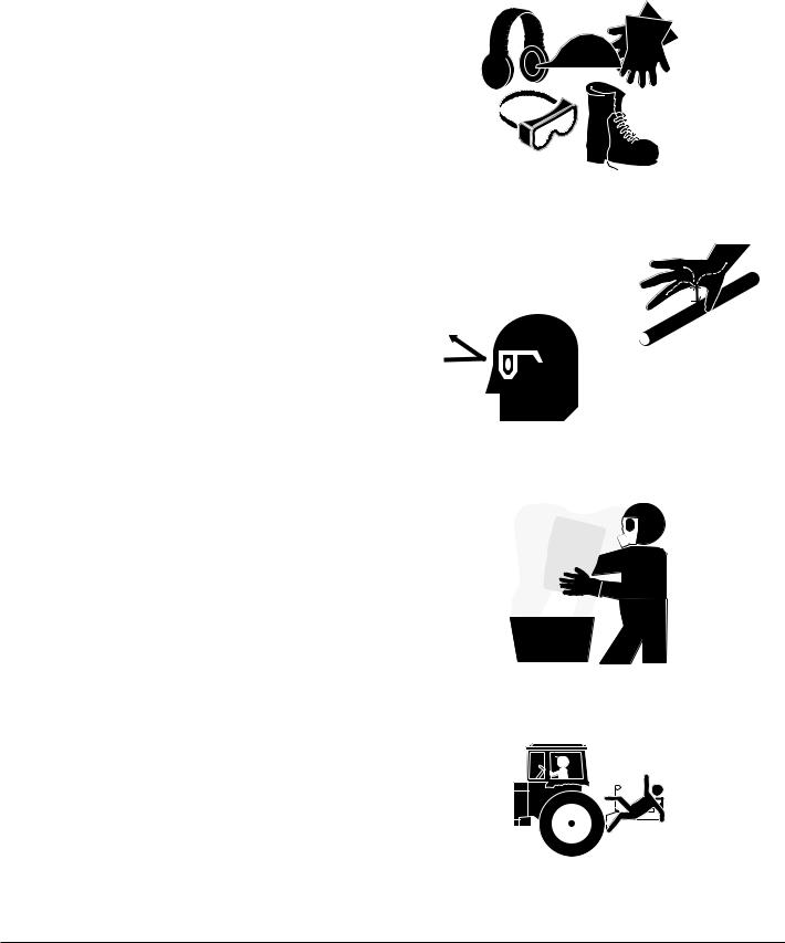
Wear Protective Equipment
▲Wear protective clothing and equipment.
▲Wear clothing and equipment appropriate for the job. Avoid loose-fitting clothing.
▲ Because prolonged exposure to loud noise can cause hearing impairment or hearing loss, wear suitable hearing protection such as earmuffs or earplugs.
▲ Because operating equipment safely requires your full attention, avoid wearing entertainment headphones while operating machinery.
Avoid High Pressure Fluids
Escaping fluid under pressure can penetrate the skin, causing serious injury.
▲ Avoid the hazard by relieving pressure before disconnecting hydraulic lines.
▲ Use a piece of paper or cardboard, NOT BODY PARTS, to check for suspected leaks.
▲Wear protective gloves and safety glasses or goggles when working with hydraulic systems.
▲If an accident occurs, seek immediate medical assistance from a physician familiar with this type of injury.
Handle Chemicals Properly
Agricultural chemicals can be dangerous. Improper use can seriously injure persons, animals, plants, soil and property.
▲ Read and follow chemical manufacturer’s instructions.
▲ Wear protective clothing.
▲Handle all chemicals with care.
▲Avoid inhaling smoke from any type of chemical fire.
▲Store or dispose of unused chemicals as specified by chemical manufacturer.
Keep Riders Off Machinery
Riders obstruct the operator’s view. Riders could be struck by foreign objects or thrown from the machine.
▲ Never allow children to operate equipment.
▲ Keep all bystanders away from machine during operation.
401-226M |
07/09/2009 |
Great Plains Manufacturing, Inc. |
3 |
|
|
|
|
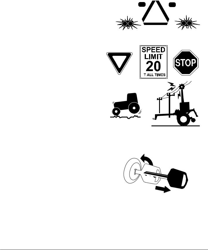
Use Safety Lights and Devices
Slow-moving tractors and towed implements can create a hazard when driven on public roads. They are difficult to see, especially at night.
▲Use flashing warning lights and turn signals whenever driving on public roads.
Use lights and devices provided with implement
Transport Machinery Safely
Maximum transport speed for implement is 20 mph (32 kph). Some rough terrains require a slower speed. Sudden braking can cause a towed load to swerve and upset.
▲Do not exceed 20 mph (32 kph). Never travel at a speed which does not allow adequate control of steering and stopping. Reduce speed if towed load is not equipped with brakes.
▲Comply with state and local laws.
▲Do not tow an implement that, when fully loaded, weighs more than 1.5 times the weight of towing vehicle.
▲Carry reflectors or flags to mark planter in case of breakdown on the road.
▲Keep clear of overhead power lines and other obstructions when transporting. Refer to transport dimensions under “Specifications and Capacities” on page 118.
▲Do not fold or unfold the planter while the tractor is moving.
Shutdown and Storage
▲Lower planter, put tractor in park, turn off engine, and remove the key.
▲Secure planter using blocks and supports provided.
▲Detach and store planter in an area where children normally do not play.
A |
OFF
07/09/2009 |
401-226M |

4 |
YP1225 and 1625 |
Great Plains Manufacturing, Inc. |
|
|
|
|
|
|
Practice Safe Maintenance
▲Understand procedure before doing work. Use proper tools and equipment. Refer to this manual for additional information.
▲Work in a clean, dry area.
▲Lower the planter, put tractor in park, turn off engine, and remove key before performing maintenance.
▲Make sure all moving parts have stopped and all system pressure is relieved.
▲Allow planter to cool completely.
▲Disconnect battery ground cable (-) before servicing or adjusting electrical systems or before welding on planter.
▲Inspect all parts. Make sure parts are in good condition and installed properly.
▲Remove buildup of grease, oil or debris.
▲Remove all tools and unused parts from planter before operation.
Tire Safety
Tire changing can be dangerous and should be performed by trained personnel using correct tools and equipment.
▲When inflating tires, use a clip-on chuck and extension hose long enough for you to stand to one side–not in front of or over tire assembly. Use a safety cage if available.
▲When removing and installing wheels, use wheel-handling equipment adequate for weight involved.
OFF
401-226M |
07/09/2009 |
Great Plains Manufacturing, Inc. |
5 |
|
|
|
|
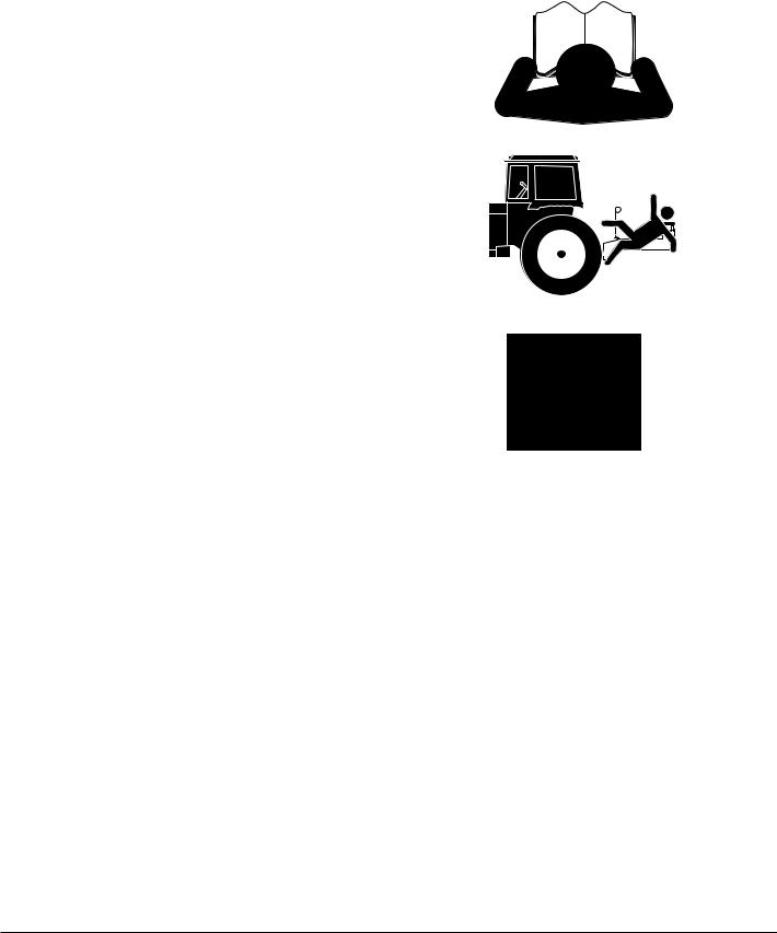
Safety At All Times
Thoroughly read and understand the instructions in this manual before operation. Read all instructions noted on the safety decals.
▲Be familiar with all planter functions.
▲Operate machinery from the driver’s seat only.
▲Do not leave planter unattended with tractor engine run-
ning.
▲ Do not dismount a moving tractor. Dismounting a moving tractor could cause serious injury or death.
▲ Do not stand between the tractor and planter during hitching.
▲Keep hands, feet and clothing away from power-driven parts.
▲Wear snug-fitting clothing to avoid entanglement with moving parts.
▲ Watch out for wires, trees, etc., when folding and raising planter. Make sure all persons are clear of working area.
07/09/2009 |
401-226M |

6 |
YP1225 and 1625 |
Great Plains Manufacturing, Inc. |
|
|
|
|
|
|
Safety Decals
Safety Reflectors and Decals
Your implement comes equipped with all lights, safety reflectors and decals in place. They were designed to help you safely operate your implement.
▲Read and follow decal directions.
▲Keep lights in operating condition.
▲Keep all safety decals clean and legible.
▲Replace all damaged or missing decals. Order new decals from your Great Plains dealer. Refer to this section for proper decal placement.
▲When ordering new parts or components, also request corresponding safety decals.
818-055C
Slow Moving Vehicle Reflector
On the back of the planter, one total
838-266C
Red Reflectors
On the back of walkboard each end and on the backside of each light mounting bar, four total
To install new decals:
1.Clean the area on which the decal is to be placed.
2.Peel backing from decal. Press firmly on surface, being careful not to cause air bubbles under decal.
27287
27287
401-226M |
07/09/2009 |
Great Plains Manufacturing, Inc. |
7 |
|
|
|
|
838-265C
Amber Reflectors
On the left-hand wing by drive, two on each side of frame when folded and two on the front of the light brackets, seven total
21963
838-267C
Daytime Reflectors
On the back of walkboard each end and on the backside of each light mounting bar, four total
27287
818-590C
Danger: Crushing Hazard
On the hitch, one total.
838-599C (Option) |
Warning: Electrocution Hazard
On marker section each end, two total
27282
27283
|
|
|
|
|
|
07/09/2009 |
401-226M |
|

8 |
YP1225 and 1625 |
Great Plains Manufacturing, Inc. |
|
|
|
|
|
|
818-339C
Warning: High Pressure Fluid Hazard
On the tongue, one total
818-580C (Option) |
Warning: Overhead Hazard
On marker section each end, two total
818-579C (Option) |
Warning: Pinch/Shear Hazard
On marker section each end, two total
818-188C |
Warning: Excessive Speed
On the tongue, one total
27282
27283
27283
27282
401-226M |
07/09/2009 |
Great Plains Manufacturing, Inc. |
9 |
|
|
|
|
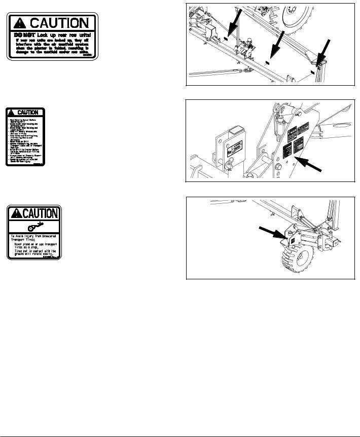
838-993C |
|
Caution: Do Not Lock Up Row Units |
|
Three on backside of each wing, six total |
27291 |
818-078C |
|
Caution: Read Operator Manual |
27282 |
|
On the tongue, one total |
|
|
818-398C |
|
|
Caution: Tires Not A Step |
21963 |
|
Above both tires, two total |
||
|
07/09/2009 |
401-226M |
10 |
YP1225 and 1625 |
Great Plains Manufacturing, Inc. |
|
|
|
|
|
|

 Introduction
Great Plains welcomes you to its growing family of new product owners. This planter has been designed with care and built by skilled workers using quality materials. Proper setup, maintenance, and safe operating practices will help you get years of satisfactory use from the machine.
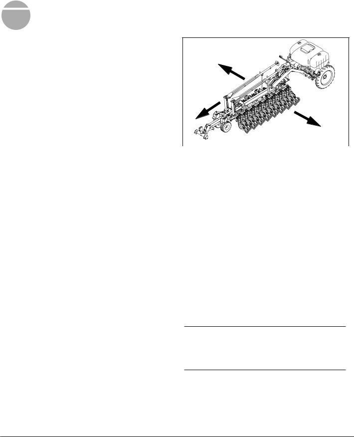
Description of Unit
The 30and 40-foot Row Yield-Pro® Planters are pulltype planting implements for use in conventional till, min- imum-till, or light no-till conditions.
Yield-Pro® Planters are outfitted with 25 Series, side- depth-control row-units. Optional unit-mounted coulters make it suitable for light to moderate no-till conditions only. These Planters fold for transport.
Document Family
401-226M |
Operator Manual (this manual) |
401-347B |
Seed Rate Manual |
401-226P |
Parts Manual |
Intended Usage
Use the planter to seed production-agriculture crops only. Do not modify the planter for use with attachments other than Great Plains options and accessories specified for use with the planter.
Covered Models
YP1225-1230 30-Foot, 12-Row, 30-Inch
YP1225-16TR36 30-Foot, 16-Row (8 Twin), 36-Inch
YP1225-1820 30-Foot, 18-Row, 20-Inch
YP1225-2315 30-Foot, 23-Row, 15-Inch
YP1225-24TR 30-Foot, 24-Row, (12 Twin) 30-Inch
YP1625-1236 40-Foot, 12-Row, 36-Inch
YP1625-1630 40-Foot, 16-Row, 30-Inch
YP1625-2420 40-Foot, 24-Row, 20-Inch
YP1625-24TR36 40-Foot, 24-Row (12 Twin), 36-Inch
YP1625-3115 40-Foot, 31-Row, 15-Inch
YP1625-32TR 40-Foot, 32-Row (16 Twin), 30-Inch
R
|
L |
|
|
Figure 1 |
27281 |
Left/Right Convention |
|
Using This Manual
This manual familiarizes you with safety, assembly, operation, adjustments, troubleshooting and maintenance. Read this manual and follow the recommendations to help ensure safe and efficient operation.
The information in this manual is current at printing. Some parts may change to assure top performance.
Definitions
The following terms are used throughout this manual.
Right-hand and left-hand as used in this manual are determined by facing the direction the machine will travel while in use unless otherwise stated.
IMPORTANT !
A crucial point of information related to the preceding topic. Read and follow the directions provided before continuing, to ensure safety, avoidance of machine damage, and to achieve desired field results.
Note: Useful information related to the preceding topic.
401-226M |
07/09/2009 |
Great Plains Manufacturing, Inc. |
Introduction |
11 |
|
|
|
|
|
|
Owner Assistance
If you need customer service or repair parts, contact a Great Plains dealer. They have trained personnel, repair parts, and equipment specially designed for Great Plains products.
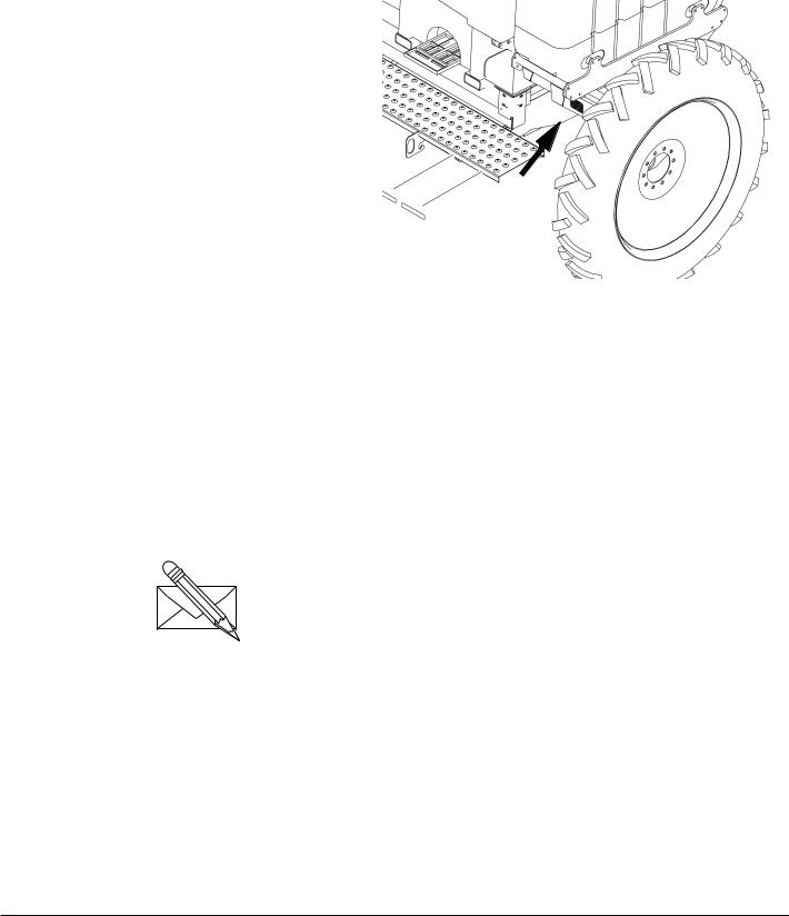
Refer to Figure 2
Your machine’s parts were specially designed and should only be replaced with Great Plains parts. Always use the serial and model number when ordering parts from your Great Plains dealer. The serial-number plate is located on the front face of the left wing rest, as shown.
Record your Yield Pro Planter model and serial number here for quick reference:
Model Number:__________________________
Serial Number: __________________________
Your Great Plains dealer wants you to be satisfied with your new machine. If you do not understand any part of this manual or are not satisfied with the service received, please take the following actions.
1.Discuss the matter with your dealership service manager. Make sure they are aware of any problems so they can assist you.
2.If you are still unsatisfied, seek out the owner or general manager of the dealership.
For further assistance write to:
Product Support
Great Plains Mfg. Inc., Service Department
PO Box 5060
Salina, KS 67402-5060
|
|
|
|
|
|
|
|
|
|
|
|
|
|
|
|
|
Figure 2 |
27284 |
|
Serial Number Plate
07/09/2009 |
401-226M |
12 |
YP1225 and 1625 |
Great Plains Manufacturing, Inc. |
|
|
|
|
|
|

 Preparation and Setup
This section helps you prepare your tractor and planter for use. Before using the planter in the field, you must hitch the planter to a suitable tractor and level the planter.
Pre-Start Checklist
1.Read and understand “Important Safety Information” on page 1.
2.Check that all working parts are moving freely, bolts are tight, and cotter pins are spread.
3.Check that all grease fittings are in place and lubricated. See “Lubrication” on page 76.
4.Check that all safety decals and reflectors are correctly located and legible. Replace if damaged. See “Safety Decals” on page 6
5.Inflate tires to pressure recommended and tighten wheel bolts as specified. See “Tire Inflation” on page 118.
Protecting Hydraulic Motor Seals
Low Pressure (Case) Drain Connection
IMPORTANT !
Case Drain Hose must be attached prior to inlet and return hoses being connected. Also, it must be unhooked last to prevent damage to the fan motor.
1.Attach case drain hose to low pressure drain connection.
Note: Case drain hose must be hooked up first. Also, it must be unhooked last to prevent damage to hydraulic motor seals.
2.Connect low pressure return hose to low pressure return connector.
IMPORTANT !
DO NOT hook case drain line to a “power-beyond port”.
3.If the tractor has a limited number of remotes capable of continuous flow, use them for the hydraulic fan and optional hydraulic drive. (See “Specifications and Capacities” on page 118 for tractor requirements.)
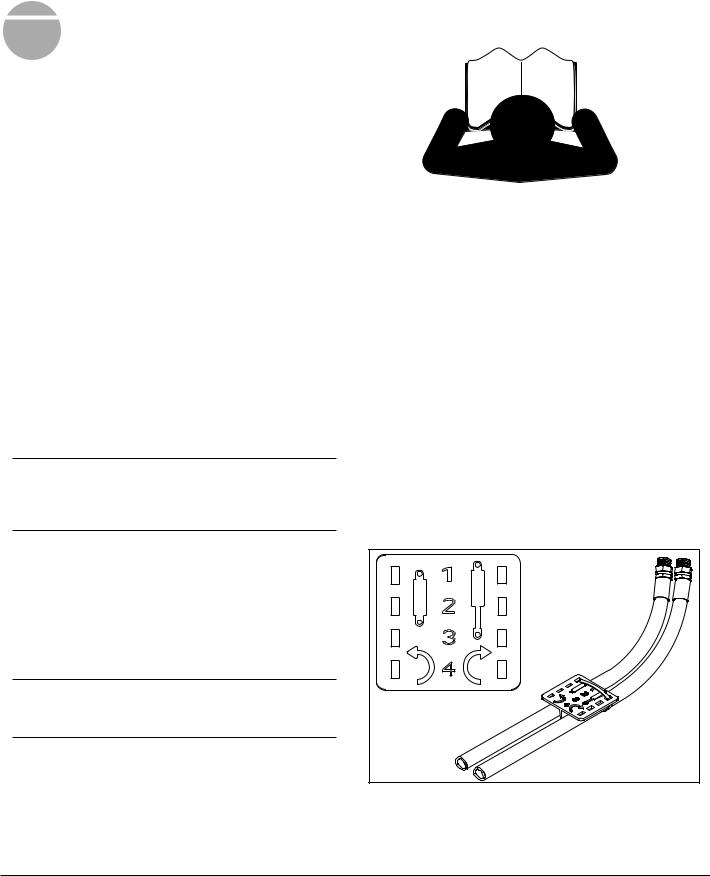
Hydraulic Hose Hookup
Great Plains hydraulic hoses are color coded. Hoses that go to the same remote valve are marked with the same color.
Color |
Hydraulic Function |
|
|
White |
Fold/Marker |
|
|
Blue |
Lift/Tongue |
Orange |
Fan |
|
|
Yellow |
Hydraulic Drive |
|
|
To distinguish hoses on the same hydraulic circuit, refer to plastic hose label. Hose under extended-cylinder symbol feeds cylinder base ends. Hose under retracted-cylin- der symbol feeds cylinder rod ends.
Figure 3 |
817-348C |
Plastic Hose Label |
17641 |
401-226M |
07/09/2009 |
Great Plains Manufacturing, Inc. |
Preparation and Setup |
13 |
|
|
|
|
|
|
Hitching Tractor to Planter
! DANGER
You may be severely injured or killed by being crushed between the tractor and planter. Do not stand or place any part of your body between planter and moving tractor. Stop tractor engine and set park brake before attaching cables and hoses.
! WARNING
Escaping fluid under pressure can have sufficient pressure to penetrate the skin causing serious injury. Avoid the hazard by relieving pressure before disconnecting hydraulic lines. Use a piece of paper or cardboard, NOT BODY PARTS, to check for leaks. Wear protective gloves and safety glasses or goggles when working with hydraulic systems. If an accident occurs, seek immediate medical attention from a physician familiar with this type of injury.
1.If returning the planter to service from storage, remove any grease used to protect cylinder rods.
3-Point Hitch
Refer to Figure 4
2.Connect your tractor 3-point to the planter 3-point hitch. If using quick hitch be sure planter locks into hitch securely.
3.Raise tractor 3-point just enough to relieve pressure off of the parking stand.
IMPORTANT !
Adjust 3-point hitch arms and sway blocks to minimize any side-to-side sway to assure proper tracking in the field and safe road travel.
4.Connect hydraulic hoses to tractor remotes. See “Hydraulic Hose Hookup” on page 12
Hydraulic Tongue Hitch
Refer to Figure 5
1.Connect the hydraulic hoses for the tongue circuit. This needs to be done before hitching in order to raise and lower the tongue.
2.Set the tongue height to clear the drawbar, back the tractor into alignment and pin the drawbar.
|
|
|
|
|
|
|
|
|
|
Figure 4 |
27282 |
3-Point Hitching
Figure 5 |
25231 |
Hitching with Hydraulic Tongue
07/09/2009 |
401-226M |
14 |
YP1225 and 1625 |
Great Plains Manufacturing, Inc. |
|
|
|
|
|
|
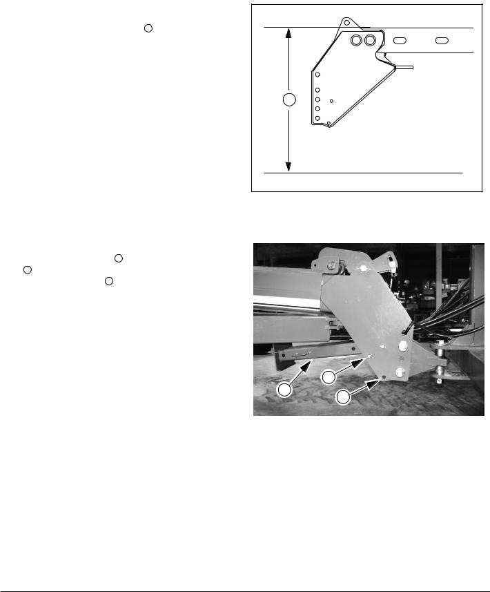
Either Hitch
3.Set the initial tongue height, using 3 point or cylinder of hydraulic tongue. Distance 1 , measured at top of tongue tube is:
46in above ground level for YP12, or 42in above ground level for YP16.
4.Connect other hydraulic hoses to tractor remotes. See “Hydraulic Hose Hookup” on page 12
5.Plug the planter light cable to the tractor.
6.Connect monitor lead to monitor harness.
7.Plug electric clutch cable to the switch control box cable.
8.Plug Veris Drive cable to the cable from the precision population controller.
Note: Switch control boxes should be mounted in your tractor cab in a location with easy access. Route wiring harnesses with enough slack to allow for tractor movement, especially on articulating tractors.
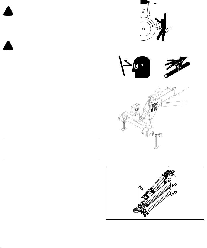
Refer to Figure 7
9. Remove the lower pin 2 holding the parking stand 3 . Swing the parking stand back and up until it is above the rear hole 4 . Place the holding pin in the rear hole and allow the parking stand to rest on it. This will be the transport position for the parking stand.
10.Adjust the top link of a 3-point long enough so the ball swivel does not bottom out when fully raised.
11.Secure hoses so they do not get caught in ball swivel. Failure to do so could cause hose to be crushed requiring hose replacement.
1 |
Figure 6 |
25316 |
Base Height
4
3 |
2 |
|
Figure 7 |
22813 |
Storing Parking Stand
401-226M |
07/09/2009 |
Great Plains Manufacturing, Inc. |
Preparation and Setup |
15 |
|
|
|
|
|
|
|
|
|
Hydraulic Charge and Bleed
Normally the hydraulic system is fully charged and bled at the factory before shipping. If repairs have been made, substantial amounts of oil drained from the system, or the following procedures do not correct a problem, see “Bleeding Hydraulics” on page 70.
Lift Hydraulics
Bleeding should not be required other than to raise fully and hold lever on for one minute or until all cylinders extend fully. If this does
Cylinder Hydraulics
Bleeding should not be required other than to fold fully and hold lever on for one minute or until all cylinders reach the end of their stroke.
IMPORTANT !
Do not fold or unfold without first raising planter completely.
Leveling Frame Side-to-Side
All frame sections must be level to maintain even planting depth. Before using the planter in the field, follow these steps to make sure the planter is level side-to-side.
Periodic frame-leveling adjustments should not be necessary, but if you are having problems with uneven depth, check planter levelness and follow these procedures.
Before making any adjustments be sure the lift cylinders are re-phased and operating properly.
Complete the steps under “Hydraulic Charge and Bleed” on page 15, before proceeding.
Note: Level frame in planting conditions. Failure to do so may result in machinery not producing desired results.
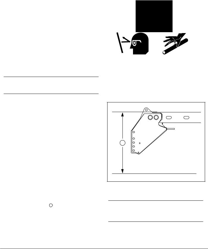
Refer to Figure 8
1.Unfold the planter fully and set down. Put in field position by lowering and pulling forward.
2.When setting hitch, lower lift cylinders completely. Set the 3-point hitch or hydraulic tongue so that the top of the tongue tube 1 is:
46in above ground for YP12, or 42in above ground for YP16.
This is the starting point for adjustments.
1 |
Figure 8 |
25316 |
Base Height
IMPORTANT !
Planter must be fully lowered to field position and hitch height must be set before making side-to-side adjustments.
07/09/2009 |
401-226M |
16 |
YP1225 and 1625 |
Great Plains Manufacturing, Inc. |
|
|
|
|
|
|
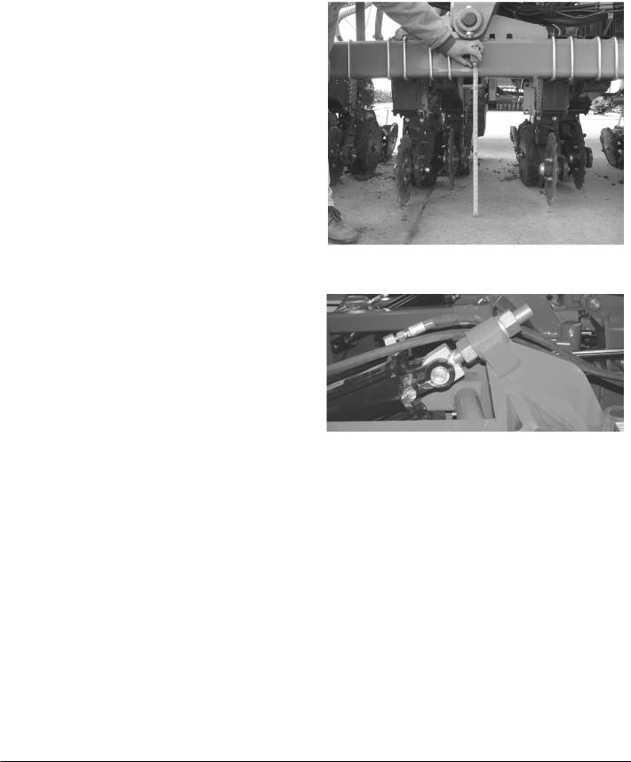
Refer to Figure 9
3.If planting 11 2in deep, adjust the hitch until frame measures approximately 26in from ground to frame at the pivots.When planting at other depths, frame height will vary.
Note: Parallel arms should be parallel with ground or up to 1in lower in back. Adjusting a 3-point hitch to level parallel arms may cause frame to sit higher or lower than 26in.
4.Check parallel arms behind the pivots to ensure that parallel arms are parallel with ground or up to 1in lower in back. If needed, raise or lower the 3-point to adjust parallel arms.
5.Once parallel arms are parallel with ground or up to 1in lower in back and 3-point is set, measure distance from ground to frame at the pivots.
Refer to Figure 10
6.Measure wings at gauge wheel. If not level with center of frame, adjust eye bolt accordingly.
Note: Eye-bolt adjustments are easier if the planter is first lowered to the ground to remove some of the force on the cylinder.
Figure 9 |
23087 |
Frame Leveling
Figure 10 |
21930 |
Eye Bolt Adjustment
401-226M |
07/09/2009 |
Great Plains Manufacturing, Inc. |
Preparation and Setup |
17 |
|
|
|
|
|
|
Wing Alignment
To check and adjust wing alignment:
1.Unfold planter, see “Unfolding the Planter” on page 22, and place a block ahead of each wing gauge wheel. Pull planter forward against blocks to rock frames back.
Refer to Figure 11
2.Check for proper alignment by running a string line across back of planter toward outer ends of wings. For proper alignment, outside ends of wings (dimension A) should be 0-to-1 4in ahead of inside ends (dimension B).
3.To adjust wing alignment, shorten or lengthen eye bolts to change the length of the wing pull bar. Adjust eye bolts 1 in or out until dimension A is 0 to 1 4in
greater than dimension B. |
Note: Angle of wings is exaggerated for ease of clarifica- |
|
|
4. Be sure both wings are adjusted equally or the |
tion. |
planter will tend to pull sideways behind the tractor. |
|
1 |
1 |
Figure 11 |
21931 |
Box Alignment
07/09/2009 |
401-226M |

18 |
YP1225 and 1625 |
Great Plains Manufacturing, Inc. |
|
|
|
|
|
|
Optional Monitor Mounting Plate
The Yield-Pro Planter® is supplied with an optional mounting plate that may be used to mount the Point Row Monitor, the Electro-hydraulic Control Valve, the Veris Monitor, and the DICKEY-john® Monitor.
Refer to Figure 12
1.If equipped with Veris, remove suction cups and mounting bracket from veris monitor. Keep suction cups and bracket for reuse.
2.Attach large suction cup included with mounting plate to the top hole on the plate using bolt and lock washer.
3.If not equipped with Veris, skip this step and continue with step 4. If equipped with Veris, using lock washers and nuts secure suction cups removed in step 1 to plate. Secure suction cups to holes directly above the bottom two holes on the plate.
4.Place DICKEY-john® mounting bracket on mounting plate. Secure bracket to plate in bottom two holes directly below the suction cups. Use bolts and nuts to install.
5.If equipped with Veris, attach Veris Drive mounting bracket above DICKEY-john® mounting bracket using the included bolts and nuts.
6.Remove mounting bracket from electro-hydraulic valve control. Install mounting bracket to mounting plate.
7.Attach point row monitor to mounting plate with 1032 x 5 8 machine screws, lock washers, and nuts. Let wires fall in the front of the plate.
8.Secure electro-hydraulic valve control to mounting bracket on plate using 10-32 x 5 8 machine screws, lock washers, and nuts. Let wires fall in the front of the plate.
9.Mount veris drive monitor to mounting bracket on plate. Secure veris drive monitor to bracket using 1/ 4-20 x 5 8 bolts, 1 4in lock washers, and 1 4-20 nuts. Wires should fall in the front of the mounting plate.
10.Attach DICKEY-john® Monitor to DICKEY-john® mounting bracket on plate. Thread monitor wires through slot in plate. Trap all other wires between DICKEY-john® monitor and mounting plate.
Point Row
Monitor
Electro-hydraulic
Valve Control
Veris Drive
Monitor
DICKEY-john®
Monitor
Figure 12 |
23283 |
Optional Monitor Mounting Plate
401-226M |
07/09/2009 |
Great Plains Manufacturing, Inc. |
Operating Instructions |
19 |
|
|
|
|
|
|

 Operating Instructions
This section covers general operating procedures. Experience, machine familiarity and the following information will lead to efficient operation and good working habits. Always operate farm machinery with safety in mind.
Pre-Start Checklist
! WARNING
Escaping fluid under pressure can have sufficient pressure to penetrate the skin. Check all hydraulic lines and fittings before applying pressure. Fluid escaping from a very small hole can be almost invisible. Use paper or cardboard, not body parts, and wear heavy gloves to check for suspected leaks. If an accident occurs, seek immediate medical attention from a physician familiar with this type of injury.
1. Carefully read “Important Safety Information” on page 1.
2.Lubricate planter as indicated under “Lubrication” on page 76.
3.Check all tires for proper inflation. See “Tire Inflation” on page 118.
4.Check all bolts, pins and fasteners. Torque as shown in “Torque Values Chart” on page 119.
5. Check planter for worn or damaged parts. Repair or replace parts before going to the field.
6. Check hydraulic hoses, fittings and cylinders for leaks. Repair or replace before going to the field.
7. Be sure hydraulic hoses are securely held out of the ball swivel area at hitch. Failure to do so could cause hoses to pinch requiring hose replacement.
07/09/2009 |
401-226M |
20 |
YP1225 and 1625 |
Great Plains Manufacturing, Inc. |
|
|
|
|
|
|
Folding the Planter
! WARNING
Pinch Point and Crushing Hazard. To prevent serious injury or death:
▲Fold only if hydraulics are bled free of air and fully charged with hydraulic oil.
▲Stay away from frame sections when they are being raised or lowered.
▲Keep away and keep others away when folding or unfolding planter.
Fold planter on level ground with tractor in neutral. If your planter has markers, be certain they are folded.
IMPORTANT !
Center section of planter will move backward while folding. Allow at least 10ft of clearance behind the planter when folding.
1. Switch drive line clutches off.
Refer to Figure 13
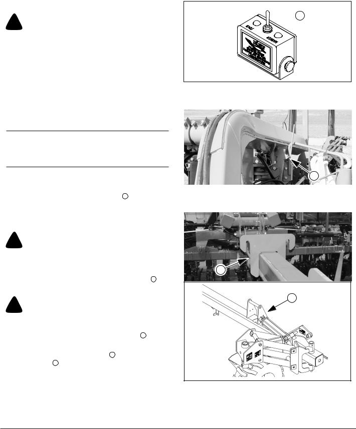
2.Set electronic valve selector switch 1 in tractor to “FOLD” to activate fold cylinder hydraulics.
3.Activate lift hydraulics. Raise planter until lift hydraulics are fully raised.
! CAUTION
Be sure planter’s lift hydraulics are fully raised before folding or machine damage WILL occur.
Refer to Figure 14
4.Fold planter until wings clear transport hooks 2 by a few feet.
! CAUTION
Failure to keep the 3-point lowered while folding WILL result in opener or seed delivery system damage.
5.Raise 3-point hitch to elevate wing hooks 3 located on the tongue above the wings.
6.Fold planter fully so wing locks 4 can engage the wing hooks 3 .
Refer to Figure 15
7.Lower 3-point hitch to engage wing hooks so tongue is carried on the wing locks. Allow hitch to float with planter frame while transporting.
 1
1
Figure 13 |
21980 |
Selector Switch
|
2 |
Figure 14 |
25030 |
Transport Hooks
3
4
Figure 15 |
22815 |
Wing Hook & Wing Lock |
27288 |
401-226M |
07/09/2009 |
Great Plains Manufacturing, Inc. |
Operating Instructions |
21 |
|
|
|
|
|
|
Refer to Figure 17 and Figure 16
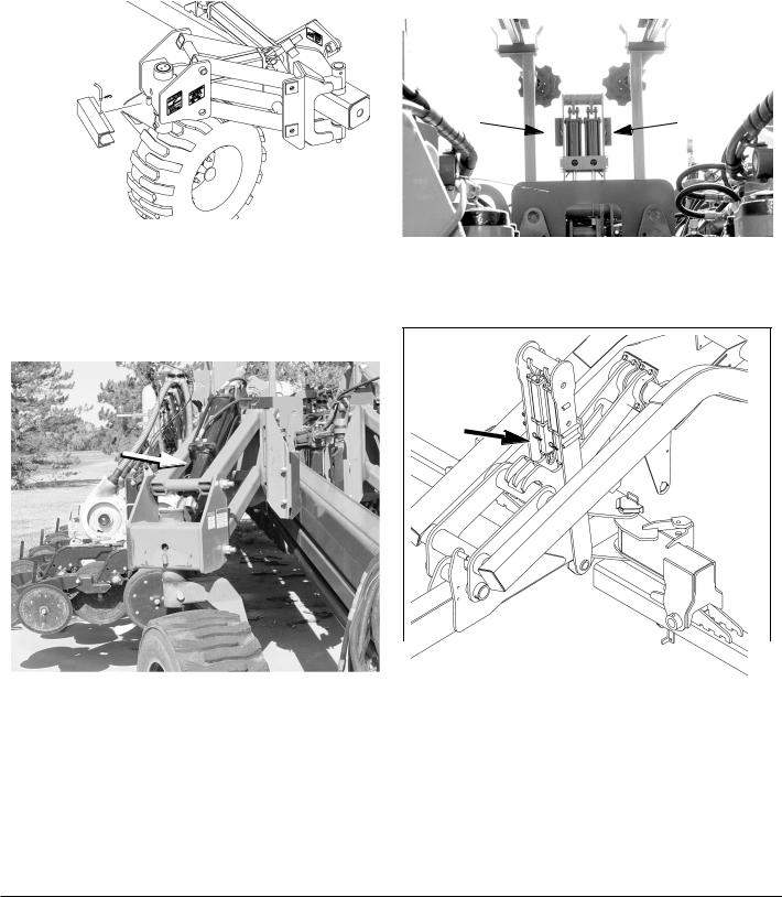
8.Remove lift cylinder transport lock channels from their storage positions.
|
|
|
|
|
|
|
|
|
|
Figure 17 |
27290 |
Transport Cylinder Lock Storage
Refer to Figure 17 and Figure 16
9.Place transport lock channels on lift cylinders located on gauge wheels and on center frame.
Figure 16 |
25029 |
Lift Cylinder Lock Storage
Figure 19 |
25028 |
|
|
|
|
|
|
||
|
Figure 18 |
27289 |
||
Transport Cylinder Lock Use |
|
|
||
|
|
|
Lift Cylinder Lock Use |
|
|
|
|
|
|
|
|
|
|
|
07/09/2009 |
401-226M |

22 |
YP1225 and 1625 |
Great Plains Manufacturing, Inc. |
|
|
|
|
|
|
Unfolding the Planter
! WARNING
To prevent serious injury or death:
▲Fold only if hydraulics are bled free of air and fully charged with hydraulic oil.
▲Stay away from frame sections when they are being raised or lowered.
▲Keep away and keep others away when folding or unfolding planter.
Unfold planter on level ground with tractor in neutral.
1. Switch drive line clutches off.
Refer to Figure 20
2.Set electronic valve selector switch 1 in tractor to “FOLD” to activate fold cylinder hydraulics.
3.Activate lift hydraulics. Raise planter until lift hydraulics are fully raised.
! CAUTION
Be sure planter’s lift hydraulics are fully raised before unfolding or machine damage WILL occur.
Refer to Figure 21
4.Raise 3-point hitch to release wing hooks.
5.The fold system uses rephasing cylinders. It is necessary to rephase cylinders so wing gauge wheels run in their fully rotated positions in front of planter. To rephase fold cylinders:
Move and hold lever in fold direction for 30 seconds. This causes wings to push against the tongue transport hooks 2 .
Refer to Figure 22
6.Reverse fold lever until wings clear transport hooks 3 by a few feet.
7.Lower 3-point hitch to planting position. See page 13 and page 28 for correct hitch height and depth control settings.
! CAUTION
Failure to lower the 3-point before unfolding WILL result in opener or seed delivery system damage.
8. Unfold planter fully to planting position.
 1
1
Figure 20 |
21980 |
Selector Switch
|
2 |
Figure 21 |
25030 |
Transport Hooks
3
4
Figure 22 |
22815 |
Wing Hook & Wing Lock |
27288 |
|
|
401-226M |
07/09/2009 |
Great Plains Manufacturing, Inc. |
Operating Instructions |
23 |
|
Refer to Figure 16 through Figure 19 on page 21. |
|
|
|
9. |
Remove lift cylinder transport lock channels from |
|
|
|
gauge wheels and center frame. Return transport |
|
|
|
lock channels to storage area. |
|
|
10. |
Activate lift hydraulics and lower planter. |
|
|
11. |
Set electronic valve selector switch in tractor to |
|
|
|
“MARKER” to activate marker hydraulics. |
1 |
|
12. |
Switch drive-line clutches on. |
|
|
Changing the Seed Box or Hopper |
|
|
|
1. |
Shut off fan before changing boxes. |
|
|
2. |
Park the planter on level ground with enough room to |
|
|
|
maneuver a tractor with front-end loader around it. |
|
|
3. |
Place tractor in park, shut off engine, and remove the |
|
|
|
key. |
|
|
4. |
Close the slide gate. |
|
|
Refer to Figure 23 |
|
|
|
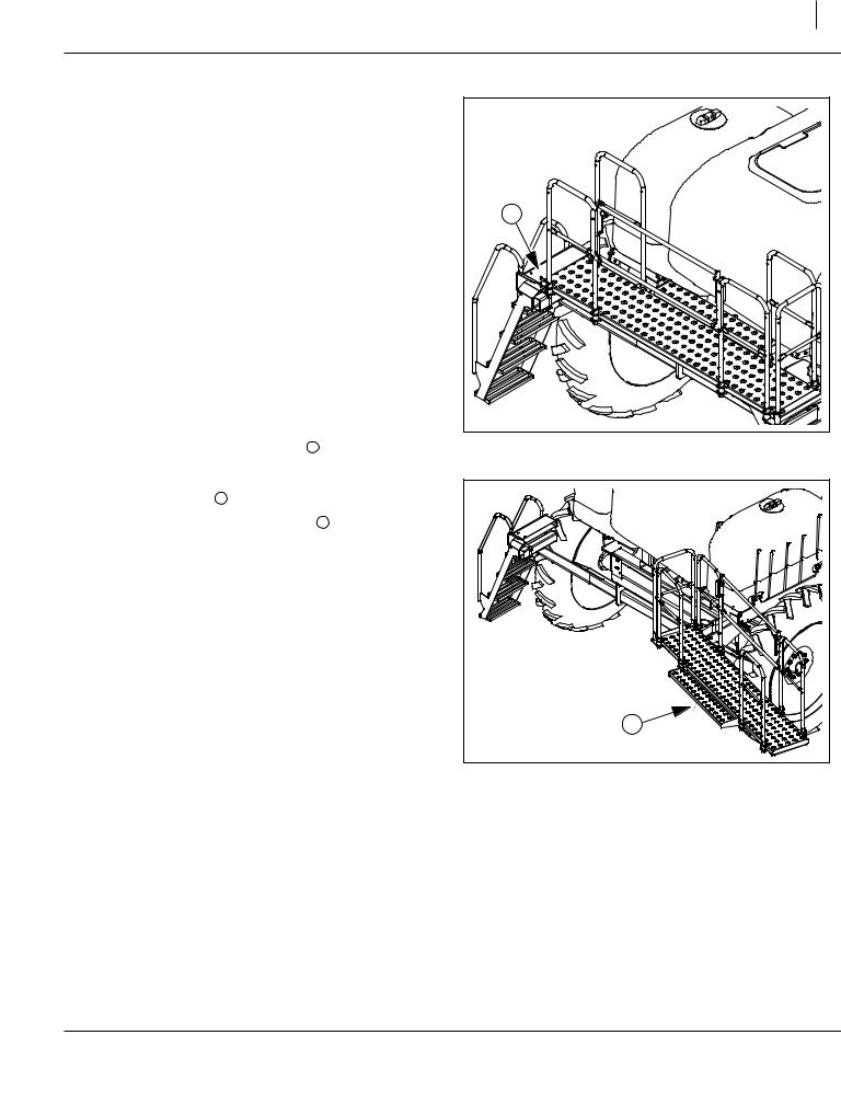
5. Remove the walkboard lock pin 1 .
Refer to Figure 24
6. Swing walkboard 2 all the way to the right.
Note: If planter is lowered, walkboard 2 will stay open by itself once fully opened.
Figure 23 |
24010 |
Walkboard Lock Pin 
2 |
Figure 24 |
24005 |
Walkboard Open
07/09/2009 |
401-226M |
24 |
YP1225 and 1625 |
Great Plains Manufacturing, Inc. |
|
|
|
|
|
|
Refer to Figure 25
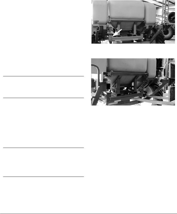
7.Remove the pins restraining the seed box or bulk hopper on the frame. (There are two lock pins one each on diagonal corners).
Refer to Figure 26
Align the forks with the slots in the rear of the seed box or hopper and slowly drive forward until forks are completely under the seed box or hopper.
Slowly lift the empty seed box or hopper from the planter.
Carefully install a full seed box or an empty hopper on the planter. Install box restraining pins in opposite corners.
Note: Bulk hopper frame has two sets of lifting points. One set is for normal loading and is tubes. The other set is to allow picking it up from the side for placing in storage near a wall.
IMPORTANT !
Never attempt to move a seed hopper while loaded. It exceeds the lifting capacity of front end loaders and most fork lifts. Always fill seed hopper with seed after it has been securely placed back on the air box.
Note: It may be necessary to adjust the seal on top of air box to get full contact with the bottom of seed box or hoppers. This is a one-time adjustment.
8.Load the hopper with seed. If using a hydraulic auger with the auxiliary hydraulic kit, refer to the instructions following.
9.Open the slide gate.
10.Return the ladder and platform to the closed position.
IMPORTANT !
Talc lubricant is mandatory for all seeds, especially treated or inoculated seed when using the precision meter. Do not use talc lubricant when using the finger pickup meters. Use graphite lubricant with finger pickup meters. Refer to “Seed Lubricants” on page 85.
Figure 25 |
25036 |
Seed Box Pins
Figure 26 |
25036 |
Fork-Lifting Seed Box
Using Auxiliary Hydraulic Circuit
The optional auxiliary hydraulic kit includes a manual valve that diverts the marker hydraulic circuit to a pair of quick-connect ports at the back of the seed cart.
1.Extend or fold any marker that is raised. Return the cab control for that circuit to “off”.
2.Close any shut-off valve on your auger, and connect the auger to the auxiliary quick-connect ports at the back of the seed cart.
3.At the auxiliary selector valve (near marker sequence valve on left wing), move the handle from “Marker” to “Auxiliary”.
4.With no seed present, open the auger shutoff valve, and operate the cab control to determine which setting (“extend” or “retract”) turns the auger in the correct direction for seed lift.
5.Load seed. Shutoff cab circuit, then auger. Return Aux valve control handle to “Marker” position.
401-226M |
07/09/2009 |

Great Plains Manufacturing, Inc. |
Operating Instructions |
25 |
|
|
|
|
|
|
Pre-Usage Checklist
Use the following checklist as a guide to ensure the planter is proper set before using. You may need to refer to the assembly instructions, operator’s manual or the Dickey-john manual to complete checklist.
MECHANICAL
1. Tongue height preset on 3-point.
2. Front to rear levelness.
3. End-to-end levelness at gauge wheels.
4. Toe in of wing frames at pull-bars.
5. Tongue hook latch operation.
6. Marker initial length.
|
|
AIR SYSTEM |
|
|
|
|
7. |
Manifold to Pro-box or poly hopper seal. |
|
|
|
|
8. |
Y-splitters turned on to correct rows. |
|
|
|
|
9. |
Air leaks (small leaks from Pro-box are nor- |
|
|
mal. |
10.Hose routings, no sags and no pinched
hoses. (Check both folded and field positions.)
11. Cleanout doors closed at meters.
12. Hoses fully connected to meters and locked.
ROW-UNITS
13. Preset depth handles to 7 holes showing above “T”
14.Preset down force springs to 1st notch
(lightest) setting for most conditions, 2nd notch otherwise.
15. Set all unit mounted coulters to same depth as opener blades - no deeper.
16. Check coulter alignment to row.
17. Check closing wheel alignment.
18. Set closing wheels to first notch (light setting).
19. Check meter drive coupler is engaged for all desired rows.
20. Lock up splitter rows if needed.
21. Check action and contact of side depth wheels.
ROW CLEANERS
22. Check for correct installation of row cleaners on all rows if equipped.
23. Check that row cleaners do not catch on hydraulic hoses.
24.Carefully watch when folding planter the
first time to ensure clearance of row cleaner.
FERTILIZER
25.Set rate drive sprockets for correct rate.
(Note fertilizer rate is population dependent.
|
26. |
Check for correct orifice plates. |
|
|
|
|
27. |
Check unused rows are correctly closed |
|
|
off. |
|
28. |
Fill system 1/2 full with water and check for |
|
|
leaks (run pump is possible). |
|
29. |
Disconnect drive chain if fertilizer is not |
|
|
used. |
30. Check all row unit lines are connected and discharge nozzles or tubes are clear.
|
|
HYDRAULIC |
|
||
31. Field raise and lower. |
||
|
|
|
|
32. |
Fold/unfold and tongue lock. |
|
|
|
|
33. |
Markers. |
|
|
|
|
34. |
Solenoid valve. |
|
|
|
|
35. |
Fan direction and speed. |
36. Veris drive (if equipped).
07/09/2009 |
401-226M |

26 |
YP1225 and 1625 |
Great Plains Manufacturing, Inc. |
|
|
|
|
|
|
DRIVE
37.Check all chains are lubricated, proper ten-
sion and move freely without kinks or tight spots. (This is very important for even metering.)
38. Set range & transmission sprockets for desired rate.
39. Check contact wheel pressure.
40.Check action of contact wheel when rais-
ing and lowering it makes contact at ground height.
41. For hydraulic drive set cal number for correct crop and row spacing.
42. For hydraulic drive pre-run system using cal mode to verify proper hydraulic action.
43. Lubricate slider joints on drive shafts if not already done.
44. Check operation of electric clutches for point rows.
|
|
METERS |
|
|
|
|
45. |
Correct meters for desired crop. (Precision |
|
|
Finger Pickup or Singulator Plus.) |
|
46. |
Correct seed wheels for desired crop. |
|
|
(Wheels for planters are green in color, not |
|
|
black.) |
|
|
|
|
47. |
Seed wheels need to be fully seated in |
|
|
meter. |
|
48. |
Correct 12 finger or 6 finger units on all |
|
|
rows for your row spacing. (Can be |
|
checked by looking into cleanout door |
|
|
|
|
|
|
opening.) |
|
||
49. Check timing of meters in Twin Row corn. |
||
|
||
50. Cleanout doors closed. |
||
|
|
|
|
51. |
Meter assemblies properly secured in |
|
|
place. |
|
52. |
Graphite for Precision Finger Pickup |
|
|
meters or Talc for Singulator Plus meters |
|
|
(per manual). |
|
|
ELECTRICAL |
|
|
|
|
53. |
Power up monitor and check settings. |
|
|
|
|
54. |
Power up and check hydraulic settings if |
|
|
not already done. |
|
55. |
Check operation of selector valve for fold/ |
|
|
makers. |
56. Check operation of lighting equipment.
401-226M |
07/09/2009 |
Loading...