


 Loading...
Great Plains Mfg., Inc.
Installation Instructions |
1 |
|
|
Dual Gauge Wheel/Spindle Update
2- and 3-Section Pull-Type Drills
Used with:
•2S-2600, 2S-2600HD, 2600-2S
•3S-3000, 3S-3000HD, 3000-3S
•3S-4000, 3S-4000HD
When you see this symbol, the subsequent instruction
!and warnings are serious - follow without exception. Your life and the lives of others depend on it!
General Information
These instructions explain how to install:
•a dual-gauge-wheel upgrade on a single-gauge-wheel drill, or
•a spindle update on an existing dual-wheel drill that has a pinned lower drive sprocket.
These instructions apply to an installation of:
Kit |
Kit Description |
195-060A |
3000 DUAL GW SKID STEER FIELD |
195-079A |
MIN-TILL DRV SPINDLE FIELD KIT |
195-122A |
DUAL GW FIELD UPDATE 2600,3000 |
One kit updates one drill (both wings). Dual-wheel drills manufactured in March 2009 or later require no kits.
Drill Model |
Kit Compatibility |
2600-2S |
All |
2S-2600 |
Serial number DD1414 or lower |
2S-2600HD |
Serial number DD1414 or lower |
3000-3S |
Serial number S1182 through S2189 |
3S-3000 |
Serial number S1182 through S2189 |
3S-3000HD |
Serial number S2189 or lower |
3S-4000 |
Serial number YY1933 or lower |
3S-4000HD |
Serial number YY1933 or lower |
Related Documents
Have the Operator Manual at hand for drill movements.
195-200M Operator, 2600-2S
195-200M-A Operator, 2S-2600
195-069M Operator, 2S-2600HD
195-110M Operator, 3000-3S
195-110M-A Operator, 3S-3000
195-068M Operator, 3S-3000HD
195-242M Operator, 3S-4000
195-067M Operator, 3S-4000HD
|
U |
B |
L |
R |
F |
|
D |
Figure 1 |
29442 |
Dual Gauge Wheel Assembly
Have the current Parts Manual at hand for parts ID.
195-200P Parts, 2600-2S and 2S-2600
195-069P Parts, 2S-2600HD
195-110P Parts, 3000-3S and 3S-3000
195-068P Parts, 3S-3000HD
195-242P Parts, 3S-4000
195-067P Parts, 3S-4000HD
Notations and Conventions |
|
U |
|
“Left” and “Right” are facing in the |
F |
|
R |
direction of machine travel. An orienta- |
|
||
|
|
|
|
tion rose in the line art illustrations |
L |
|
B |
|
|||
shows the directions of Left, Right, |
|
||
Front, Back, Up, Down. |
|
D |
|
|
|
|
|
©Copyright 2009 |
Printed 04/10/2009 |
195-080M |
Great Plains Mfg., Inc.
2 Dual Gauge Wheel/Spindle Update
Call-Outs
1 to 9
11 to 39
Single-digit callouts identify components in the currently referenced Figure or Figures. These numbers may be reused for different items from page to page.
Two-digit callouts in the range 11 to 39 reference new parts from the new parts lists beginning on page 20.
51 to 70 Two-digit callouts in the range 51 to 70 reference affected existing parts from the table on page 22. The descriptions match those in your Parts Manual. The narrative and table indicate any re-use of the parts.
Before You Start
Compatibility
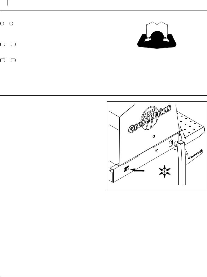
Refer to Figure 2
1.Make sure that the drill is a compatible model. Check the serial number plate against the table on page 1. Verify from the serial number that the drill is compatible with this kit.
Early model 3000-3S and 3S-3000 drills have an incompatible hub size.
Inventory
2.Make sure all parts are present.
Comprehension
3.Review these instructions. Make sure the installers understand where each part or assembly is installed, and what tools are required for the task.
Note: Illustrations in this manual, based on the parts manuals for this family of drills, may show exploded views that are fully disassembled. Rely on the instructions for required disassembly and reassembly steps.
|
U |
R |
B |
F |
L |
|
D |
Figure 2 |
15614 |
Serial Number Plate
195-080M |
04/10/2009 |

Great Plains Mfg., Inc.
Installation Instructions |
3 |
|
|
Pre-Assembly Preparation
Tools Required
•updated drill Parts Manual (see page 1)
•suitable tractor for positioning, unfolding and lowering drill
•blocks for securing transport tires if drill will be unhitched for the work
•a jack or stand for elevating one gauge wheel weldment at a time
•bearing seal removal and seating tools; if specialized tools are not available, substitute two lengths of thick (e.g. Schedule 40) plastic pipe with outside diameters:
A.inside seal: 3 to 33⁄8in (7.62 to 8.57cm), and
B.outside seal: 31⁄2 to 37⁄8in (8.89 to 9.84cm)
C.bearing cup: 31⁄2 to 33⁄4in (8.89 to 9.52cm)
A length of about 1ft (30cm) suffices. A cap on one end would provide a tapping surface for a mallet.
For seating the shallow inside seal, use a flat metal plate, about 3⁄4in x 4in and 12in long (2x5x30cm).
•a length of steel or iron pipe, 13⁄8in (3.5cm) I.D. or larger, and a length of 3 to 5 feet (just over a meter)
•de-greasing fluids, anti-seize compound, and bearing grease
•basic hand tools, including: 21⁄4in (5.8cm) hex socket 5⁄16in (7.5 to 7.9mm) punch
04/10/2009 |
195-080M |
Great Plains Mfg., Inc.
4 Dual Gauge Wheel/Spindle Update
Prepare Drill
Work Location
4.Move the drill to a location with:
•room to unfold it, as well as move it forward and back several feet (a few meters),
•access to tractor or hydraulic power,
•adequate illumination, and;
•clear surface beneath for recovery of any falling or dropped parts - if the surface is not clear, have
a tarp or drop cloth available.
Remove Ground Drive Chains
5.Fully unfold drill. Raise drill.
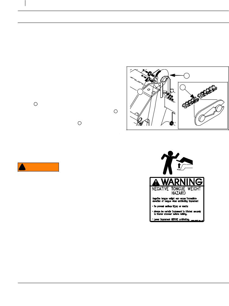
Refer to Figure 3
6.Pull drill forward until, at the left gauge wheel, the clip 1 joining the chain ends is accessible.
7.Loosen the nut and bolt securing the slotted idler 2 . Relax the idler in the slot.
8.Remove and save the chain 3 .
9.Repeat step 6 through step 8 for the right wing.
Prepare Drill for Installation
10.Position the drill at the installation site.
11.Install parking stands if drill is so equipped.
12.Lower the drill. Lower the openers.
! WARNING
Negative tongue weight hazard:
Do not unhitch until fully lowered. Some of these drills can have significant negative tongue weight when fully unfolded and raised. The tongue can fly up during transport or opener lift, if using stationary hydraulic power to operate drill.
13.Put the lift circuits in Float.
14.Shut off tractor or hydraulic source. Put tractor in Park.
3 |
1 |
2 |
Figure 3 |
29445 |
Dismount Chain |
26482 |
|
195-080M |
04/10/2009 |
Great Plains Mfg., Inc. |
|
|
|
|
Installation Instructions |
5 |
|
Remove Existing Spindle |
|
|
|
Step 16 through step 91 are for one wing. Start with the |
|
|
|
left wing. |
|
|
|
Release Spindle Nut and Wheel Bolts |
56 |
|
|
Existing spindle nuts may be difficult to remove due to |
|
|
|
|
|
|
|
exposure to the elements. Loosen them before dis- |
|
|
|
mounting wheels. |
|
|
|
Refer to Figure 4 |
65 |
|
|
15. Identify the spindle nut style used on your drill. |
|
|
|
For ring-style bearing nuts 58 , go to step 16. |
|
|
|
For castellated (slotted) nuts 59 , skip to step 19. |
|
|
|
16. At the ground drive, remove the outer: |
|
|
|
58 803-208C NUT BRG LOCK, TN-10 |
59 |
|
|
and |
|
|
|
58 |
|
|
|
62 804-098C WASHER BRG LOCK, TW110 |
|
|
|
62 |
|
|
|
These parts are not re-used. |
|
|
|
17. Loosen, but do not remove the inner: |
|
|
|
58 803-208C NUT BRG LOCK, TN-10 |
58 |
|
|
and all: |
|
|
|
56 802-104C BOLT WHEEL 1/2-20X1 90-DEG |
|
|
|
18. If step 16 and step 17 were done, skip to step 21. |
|
|
|
19. At the ground drive, remove one: |
56 |
|
|
65 805-148C PIN COTTER 3/8 X 3 PLT |
|
|
|
The cotter pin is not re-used. |
|
|
|
20. Loosen, but do not remove: |
|
|
|
59 803-239C NUT HEX SLOTTED 1 1/2-12 PLT |
Figure 4 |
29445 |
|
and all: |
|
||
Release Existing Spindle Nuts |
|
|
|
56 802-104C BOLT WHEEL 1/2-20X1 90-DEG |
|
|
|
|
|
|
|
Release Existing Sprocket |
|
|
|
Refer to Figure 5 |
|
|
|
21. Jack up the wing ground drive weldment. Locate the |
66 |
54 |
|
inner sprocket 66 inside the lower weldment. |
|
||
|
|
|
|
22. Rotate spindle 54 until roll pin 64 is accessible. |
|
|
|
23. Drive out roll pin: |
64 |
|
|
64 805-030C PIN ROLL 5/16 X 3 PLT |
|
|
|
|
|
|
|
This pin is not re-used. |
|
|
|
Figure 5 |
29445 |


 Release Existing Sprocket
04/10/2009 |
195-080M |

Great Plains Mfg., Inc.
6 Dual Gauge Wheel/Spindle Update
Dismount Wheel(s) and Hub(s) |
|
56 |
|
|
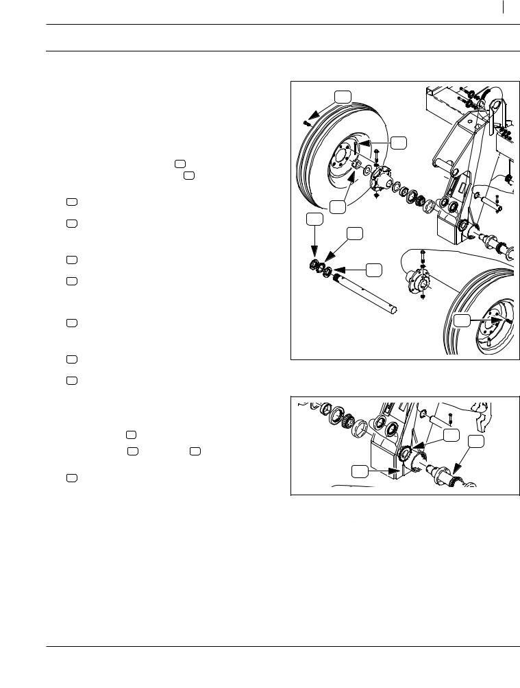
Refer to Figure 6 |
|
|
||
24. Remove and save six (6) or twelve (12) existing: |
|
59 |
|
|
56 |
802-104C BOLT WHEEL 1/2-20X1 90-DEG |
|
|
|
Dismount and save the wheels: |
|
|
|
|
53 |
161-046K 6 BOLT WHL&TIRE 8 PLY TUBELESS |
|
|
|
25. Remove the spindle nut loosened at step 17 or |
|
|
|
|
step 20. |
|
|
|
|
58 |
803-208C NUT BRG LOCK, TN-10 |
|
|
|
No save. This style nut is not re-used. |
|
63 |
|
|
|
|
|
|
|
59 |
803-239C NUT HEX SLOTTED 1 1/2-12 PLT |
|
|
|
Save. This nut is re-used. |
|
|
|
|
26. Remove and save any washer: |
|
58 |
|
|
63 |
804-182C WASHER HARD 1 1/2 MILCARB GR8 |
|
|
|
27. Remove and save one or two sets: |
|
57 |
|
|
60 |
803-263C NUT HEX FLANGE LOCK 5/8-11 PLT |
|
61 |
|
61 |
804-095C WASHER FLAT 5/8 HARD ASTMF436 |
|
|
|
|
|
|
||
57 |
802-687C HHCS 5/8-11X4 SPTHD GR8 |
|
52 |
|
28. Remove and save one or two: |
|
60 |
|
|
52 |
152-390D 6-BOLT HEAVY DRIVE HUB 2 BORE |
|
|
|
|
53 |
|
||
Save the hub(s) if your kit is 195-079A spindle |
|
|
||
|
56 |
|
||
update only. The other kits include new hubs. |
|
|
||
|
|
|
Figure 6 |
29445 |
|
|
|
Dismount Wheel(s) and Hub(s) |
|
Remove Old Spindle |
|
|
|
|
Refer to Figure 7 |
|
|
|
|
29. Remove and save one: |
|
|
|
|
63 |
804-182C WASHER HARD 1 1/2 MILCARB GR8 |
|
54 |
|
30. Remove and save two: |
|
|
||
63 |
|
51 |
||
51 |
120-198D AXLE SPACER TUBE |
51 |
||
31. Remove one each: |
|
66 |
|
|
54 |
195-229D SPNDLE 2"W/5/8 CROSS HOLE DUAL |
|
|
|
|
|
|
||
66 |
808-287C SPKT 50B19C2B W/5/16 HOLE |
|
|
|
These parts are not re-used. |
|
|
|
|
|
|
|
Figure 7 |
29445 |
|
|
|
Remove Spindle |
|
195-080M |
04/10/2009 |
Great Plains Mfg., Inc.
Installation Instructions |
7 |
Remove Seals and Bearings
Because the new spindle and sprocket hub must be clean and dry when assembled, the existing bearings must be at least partially disassembled.
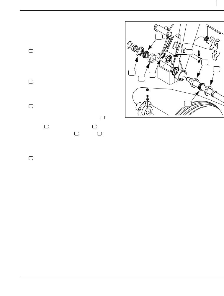
Refer to Figure 8 |
|
69 |
|
|
32. Use a bearing seal puller, or right-angle pry tools, to |
|
|
|
|
|
remove two: |
|
|
|
|
68 816-138C SEAL DBL LIP 2.5 ID X 3.881 OD |
|
67 |
|
Note: Removing seals is likely to result in seal damage, |
|
|
70 |
|
|
rendering them unsuitable for re-use. The bearing |
|
|
|
|
cone and cup, however, are re-used. Exercise |
|
|
68 |
|
care to prevent damage to the bearings. |
68 |
67 |
|
33. Remove and save two: |
|
|||
|
|
|||
|
70 |
|
||
|
69 822-117C BRG CONE 2.00ID TIM33889 |
|
|
|
|
|
|
|
|
|
These cones are re-used, unless being indepen- |
|
|
|
|
dently replaced due to wear or damage. |
|
|
|
34. Use a bearing seal puller, or right-angle pry tools, to |
|
|
|
|
|
remove two: |
|
69 |
|
|
67 816-012C SEAL 3.375 X 2.0 X.438 CR20125 |
|
|
|
|
|
|
|
|
|
These seals are not re-used. |
|
|
|
35. |
Clean, de-grease and dry bearing cones 69 and |
|
Figure 8 |
29445 |
|
weldment through-holes (which still have the bear- |
|
||
|
|
Remove Seals and Bearings |
|
|
|
ing cups 70 and inner bearing seals 67 present). |
|
|
|
|
|
|
|
|
36. |
Inspect the bearing cones 69 and cups 70 for signs |
|
|
|
|
of wear and damage. The kits do not include new |
|
|
|
|
bearings, but they should be replaced if not in ser- |
|
|
|
|
viceable condition. |
|
|
|
37. If bearings must be replaced, remove two:
70 822-118C BRG CUP 3.75OD TIM33821
The bearing cups are re-used, unless being independently replaced due to wear or damage.
04/10/2009 |
195-080M |
Great Plains Mfg., Inc.
8 Dual Gauge Wheel/Spindle Update
Install New Spindle
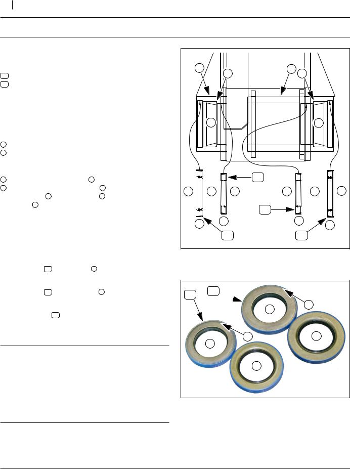
About Bearing Seals
Refer to Figure 9 and Figure 10
The new bearing seals are supplied in two sizes:
26816-012C SEAL 3.375 X 2.0 X.438 CR20125
27816-138C SEAL DBL LIP 2.5 ID X 3.881 OD
The smaller diameter (inside) seals are installed into the axle-cup weldments from the inside of the gauge wheel weldment. The larger diameter (outside) seals are installed from the outside.
Note that there are two different axle-cup weldments on each gauge wheel:
1a long hub, where the seal seats deeply, and
2a short (shallow) hub.
These are reversed left-to-right on each side.
Bearing seals have distinct faces:
3inner - toward sealed area 5 (bearing)
4outer - away from sealed area 5 (bearing), and The inner face 3 has the seams 6 of the shells. The
outer face 4 has any printing on the housing. If the seal has a visible taper at the outside diameter, the smaller diameter side is the inside.
The seals and keyless hub must be installed in a specific order, depending on the tools available. Using the suggested tools, the order used in these instructions is:
a.bearing cups (if not left in place)
b.inside seal 26 in deep hub 1 .
c.keyless hub (not shown on this page)
d.inside seal 26 in shallow hub 2
e.bearing cones (not shown on this page)
f.outside seals 27 .
If using different tools, rehearse the sequence before starting work.
IMPORTANT !
Seals are hollow metal structures and are somewhat fragile. The are not intended to be in contact with the bearings. When installing them, carefully align them so they are concentric with the shaft hole. Apply insertion force across the entire face, or at least equally along the entire outside diameter (as close to the shaft diameter as possible). See page 3 for tool suggestions.
|
2 |
a |
1 |
a |
|
|
|
|
|||
|
5 |
|
|
5 |
|
|
|
|
26 |
|
|
4 |
3 |
4 |
4 |
3 |
4 |
|
|
|
26 |
|
|
|
f |
d |
|
b |
f |
|
27 |
|
27 |
||
|
|
|
|
Figure 9 |
29448 |
Seal Locations
26 27
3 6
6 |
4 |
3
4
Figure 10 |
29447 |
Bearing Seals
195-080M |
04/10/2009 |
Loading...