

Page 1
1
Page 2
Contents
Contents
Program descriptions in detail
Page Page
Memories
Model select 59 59
Copy / Erase 60 60
Suppressing codes 62 62
Suppressing models 62 62
Basic transmitter, model and servo settings
Base setup model 64 66
Model type 70
Helicopter type 72
Servo adjustment 74 74
Transmitter controls
Stick mode 76 77
Transmitter control settings 78 80
Throttle limit 82
Dual Rates / Exponential 86 88
Channel 1 curve 90 92
Switches
Switch display 93 93
Control switches 94 94
Logical switches 97 97
Flight phases
How do I program a fl ight phase? 98 98
Phase settings 100 102
Phase assignment 104 104
Phase trim F3B 105
Non-delayed channels 105 105
2
Page
Page
Timers
Timers (general) 106 106
Flight phase timers 108 108
Mixers
What is a mixer? 110 110
Wing mixers 110
Helicopter mixers 122
Setting up the throttle and
collective pitch curve
129
Auto-rotation 132
General notes on freely
programmable mixers
134
134
Free Mixers 135 135
MIX aktive in phase 142 142
Mix only channel 142 142
Dual mixers 144 144
Swashplate mixers 145
Special functions
Fail-Safe settings, PCM 20 146 146
Fail-Safe settings, SPCM 20 148 148
Fail-Safe settings, APCM 20 149 149
Trainer (teacher / pupil) mode 150 150
Receiver output swap 153 153
Global functions
General basic settings 154 154
Servo display 156 156
Servo test 156 156
Code lock 157 157
General notes
Safety notes ............................................................... 4
Foreword ....................................................................7
mx-24s Computer System ....................................... 8
Operating notes .......................................................12
DSC socket .............................................................. 18
Description of transmitter ......................................... 20
Description of screen ............................................... 22
Using the system for the fi rst time ........................... 23
Preliminary notes ................................................ 23
Selecting the language ....................................... 23
Frequency scanner ............................................. 24
Selecting the channel ......................................... 25
Receiving system ....................................................26
Installation notes ................................................27
Defi nition of terms ................................................... 28
Signal fl ow chart ................................................. 29
Basic operations ...................................................... 30
Button pad .......................................................... 30
Rotary control ..................................................... 30
Hotkeys ............................................................... 30
Menu settings ..................................................... 31
Assigning transmitter controls,
switches and control switches ................................. 32
Digital trims / Cut-off trim ......................................... 34
Fixed-wing model aircraft ........................................36
Receiver socket sequence .................................37
Model helicopters ....................................................42
Receiver socket sequence .................................43
Programming – a brief introduction
Brief programming instructions ................................ 44
Program descriptions
Setting up a new model memory ............................. 58
Page 3
Programming examples
Fixed-wing models (general) ................................. 158
Fixed-wing model gliders ....................................... 160
Including an electric power system ........................ 165
C1 stick doubling as control for:
Electric motor and butterfl y (crow) .................... 167
Electric motor and airbrakes ............................. 169
Operating timers using a stick function or switch ...170
Servos running in parallel ...................................... 172
Two airbrake or spoiler servos .......................... 172
Multi-motor power models ................................ 172
Two elevator servos .......................................... 173
Two rudder servos ............................................ 173
Using fl ight phases ................................................ 174
Controlling timed sequences ................................. 182
Eight-fl ap wing .......................................................184
Delta / fl ying wing model aircraft ............................ 188
F3A models ...........................................................192
Model helicopters ..................................................196
Appendix
Trainer system accessories ................................... 204
Transmitter accessories ......................................... 205
Approved operating frequencies ............................ 206
Conformity declaration ........................................... 207
Index ...................................................................... 208
Guarantee certifi cate ............................................. 215
3
Contents
Notes on environmental protection
The presence of this symbol on a product,
in the user instructions or the packaging,
means that you must not dispose of that
item, or the electronic components contai-
ned within it, in the ordinary domestic waste when the product comes to the end of its useful life.
The correct method of disposal is to take it to your local collection point for recycling electrical and electronic equipment.
Individual markings indicate which materials can be
recycled and re-used. You can make an important
contribution to the protection of our shared environment by re-using the product, recycling the basic materials or re-processing redundant equipment in other
ways.
Dry cells and rechargeable batteries must be removed from the device and taken separately to a suitable battery disposal centre.
If you don’t know the location of your nearest disposal
centre, please enquire at your local authority offi ce.
Environmental
protection notes
Page 4

We all want you to have many hours of pleasure in
our mutual hobby of modelling, and safety is an important aspect of this. It is absolutely essential that
you read right through these instructions and take careful note of all our safety recommendations.
If you are a beginner to the world of radio-controlled
model aircraft, boats and cars, we strongly advise
that you seek out an experienced modeller in your
fi eld and ask him for help and advice.
These instructions must be handed on to the new ow-
ner if you ever sell or dispose of the transmitter.
Application
This radio control system may only be used for the
purpose for which the manufacturer designed it, i.e.
for operating radio-controlled models which do not
carry humans. No other type of use is approved or
permissible.
Safety notes
SAFETY IS NO ACCIDENT
and
RADIO-CONTROLLED MODELS ARE NOT
PLAYTHINGS
Even small models can cause serious personal injury and damage to property if they are handled incompetently.
Technical problems in electrical and mechanical sys-
tems can cause motors to rev up or burst into life unexpectedly, with the result that parts may fl y off at great speed, causing series injury.
Short-circuits of all kinds must be avoided at all times.
Short-circuits can easily destroy parts of the radio
control system, but even more dangerous is the acute risk of fi re and explosion, depending on the circumstances and the energy content of the batteries.
Propellers (aircraft and boat), helicopter rotors, open
gearboxes and all other rotating parts which are driven by a motor or engine represent a permanent in-
jury hazard. Do not touch these items with any object
or part of your body. Remember that a propeller spinning at high speed can easily slice off a fi nger. Ensure that no other object can make contact with the driven components.
Never stand in the primary danger zone, i. e. in the
rotational plane of the propeller or other rotating parts,
when the motor is running or the drive battery is connected.
If an internal-combustion engine or electric motor is
connected to the system, take great care to avoid
any possibility of it bursting into life when you are programming the transmitter. We recommend that you
disconnect the fuel supply or the drive battery beforehand.
Protect all electronic equipment from dust, dirt, damp,
and foreign bodies. Avoid subjecting the equipment
to vibration and excessive heat or cold. Radio control
equipment should only be used in “normal” ambient
temperatures, i. e. within the range -15°C to +55°C.
Avoid subjecting the equipment to shock and pressure. Check the units at regular intervals for damage to
cases and leads. Do not re-use any item which is damaged or has become wet, even after you have dried
it out thoroughly.
Use only those components and accessories which
we expressly recommend. Be sure to use only genuine matching GRAUPNER connectors of the same design with contacts of the same material. If you are still
using plug-in crystals, use only genuine GRAUPNER
crystals on the appropriate frequency band.
When deploying cables note that they must not be under tension, and should never be bent tightly or kinked, otherwise they may fracture. Avoid sharp edges
which could wear through the cable insulation.
Check that all connectors are pushed home fi rmly before using the system. When disconnecting components, pull on the connectors themselves – not on the
wires.
It is not permissible to carry out any modifi cations
to the RC system components. Avoid reverse polarity and short-circuits of all kinds involving the connecting leads, as the equipment is not protected against
such errors.
Installing the receiving system and deploying the
receiver aerial
In a model aircraft the receiver must be packed in
soft foam and stowed behind a stout bulkhead, and
in a model boat or car should be protected effectively
from dust and spray.
The receiver must not make contact with the fuselage,
hull or chassis at any point, otherwise motor vibration
and landing shocks will be transmitted directly to it.
When installing the receiving system in a model powered by a glowplug or petrol engine, be sure to install all the components in well-protected positions
so that no exhaust gas or oil residues can reach the
units and get inside them. This applies above all to
the ON / OFF switch, which is usually installed in the
outer skin of the model.
Secure the receiver in such a way that the aerial, servo leads and switch harness are not under any strain.
The receiver aerial is permanently attached to the re-
ceiver. It is about 100 cm long and must not be shortened or extended. The aerial should be routed as far
away as possible from electric motors, servos, metal pushrods and high-current cables. However, it is
best not to deploy the aerial in an exactly straight line,
but to angle it: e. g. run it straight to the tailplane, then
leave the fi nal 10 - 15 cm trailing freely, as this helps
to avoid reception “blind spots” when the model is in
the air. If this is not possible, we recommend that you
lay out part of the aerial wire in an S-shape inside the
model, close to the receiver if possible.
Safety notes
Please read carefully!
4
Safety notes
Page 5

Installing the servos
Always install servos using the vibration-damping
grommets supplied. The rubber grommets provide
some degree of protection from mechanical shocks
and severe vibration.
Installing control linkages
The basic rule is that all linkages should be installed
in such a way that the pushrods move accurately, smoothly and freely. It is particularly important that
all servo output arms can move to their full extent without fouling or rubbing on anything, or being obstructed mechanically at any point in their travel.
It is important that you can stop your motor at any
time. With a glow motor this is achieved by adjusting
the throttle so that the barrel closes completely when
you move the throttle stick and trim to their end-points.
Ensure that no metal parts are able to rub against
each other, e. g. when controls are operated, when
parts rotate, or when motor vibration affects the model. Metal-to-metal contact causes electrical “noise”
which can interfere with the correct working of the receiver.
Always extend the transmitter aerial fully before
operating your model
Transmitter fi eld strength is at a minimum in an ima-
ginary line extending straight out from the transmitter aerial. It is therefore fundamentally misguided to
“point” the transmitter aerial at the model with the idea
of obtaining good reception.
When several radio control systems are in use on ad-
jacent channels, the pilots should always stand together in a loose group. Pilots who insist on standing
away from the group endanger their own models as
well as those of the other pilots.
Pre-fl ight checking
If there are several modellers at the site, check carefully with all of them that you are the only one on
“your” channel before you switch on your own trans-
mitter. If two modellers switch on transmitters on the
same channel, the result is interference to one or
both models, and the usual result is at least one wrecked model.
Before you switch on the receiver, ensure that the
throttle stick is at the stop / idle end-point.
Always switch on the transmitter fi rst, and only
then the receiver.
Always switch off the receiver fi rst, and only then
the transmitter.
If you do not keep to this sequence, i. e. if the receiver is at any time switched on when “its” transmitter
is switched off, then the receiver is wide open to signals from other transmitters and any interference, and
may respond. The model might then carry out uncontrolled movements, which could easily result in personal injury or damage to property. The servos may run
to their end-stops and damage the gearbox, linkage,
control surface etc.
Please take particular care if your model is fi tted with
a mechanical gyro:
Before you switch your receiver off, disconnect the
power supply to ensure that the motor cannot run up
to high speed accidentally.
Gyros can generate such high voltages as they
run down that the receiver picks up apparently
valid throttle commands, and the motor could re-
spond by accelerating unexpectedly.
Range checking
Before every session check that the system works
properly in every respect, and has adequate range.
This means checking that all the control surfaces re-
spond correctly and in the appropriate direction to the
transmitter commands, at a suitable ground range.
Repeat this check with the motor running, while an
assistant holds the model securely for you.
Operating your model aircraft, helicopter, boat or
car
Never fl y directly over spectators or other pilots, and
take care at all times not to endanger people or animals. Keep well clear of high-tension overhead cables.
Never run your model boat close to locks and fullsize boats. Model cars should never be run on public
streets or motorways, footpaths, public squares etc..
Checking the transmitter and receiver batteries
It is essential to stop using the radio control system
and recharge the batteries well before they are completely discharged. In the case of the transmitter this
means – at the very latest – when the message “Bat-
tery must be charged” appears on the screen, and
you hear an audible warning signal.
It is vital to check the state of the receiver battery at
regular intervals. When the battery is almost fl
at you
may notice the servos running more slowly, but it is
by no means safe to keep fl ying or running your model until this happens. Always replace or recharge the
batteries in good time.
Keep to the battery manufacturer’s instructions and
don’t leave the batteries on charge for a longer period than stated. Do not leave batteries on charge unsupervised.
Never attempt to recharge dry cells, as they may explode.
Rechargeable batteries should always be recharged before every session. When charging batteries
it is important to avoid short-circuits. Do this by connecting the charge lead banana plugs to the charger
fi rst, taking care to maintain correct polarity. Only then
connect the charge lead to the transmitter or receiver
battery.
Disconnect all batteries and remove them from your
model if you know you will not be using it in the near
future.
5
Safety notes
Page 6

Capacity and operating times
This rule applies to all forms of electrical power sour-
ce: capacity is greatly reduced at low temperatures,
i. e. operating times are shorter in cold conditions.
Frequent charging of batteries, and use of battery
maintenance programs, can also result in a gradual
loss of battery capacity. For this reason you should always check the actual capacity of your packs at regular intervals - every six months at least.
Purchase only genuine GRAUPNER batteries!
Suppressing electric motors
All conventional electric motors produce sparks bet-
ween commutator and brushes, to a greater or lesser
extent depending on the motor type; the sparking generates serious interference to the radio control system.
In electric-powered models every motor must therefore be thoroughly suppressed. Suppressor fi lters effectively eliminate such interference, and should always be fi tted.
Please read the notes and recommendations supplied by the motor’s manufacturer. Refer to the main
GRAUPNER FS catalogue for more information on
suppressor fi lters.
Servo suppressor fi lters for extension leads
Order No. 1040
Servo suppressor fi lters are required if you are obli-
ged to use long servo extension leads, as they eliminate the danger of de-tuning the receiver. The fi lter is
connected directly to the receiver input. In very diffi cult cases a second fi lter can be used, positioned close to the servo.
Using electronic speed controllers
Electronic speed controllers must be chosen to suit
the size of electric motor which they will control.
There is always a danger of overloading and possibly
damaging the speed controller, but you can avoid this
by ensuring that the controller’s current-handling capacity is at least half the motor’s maximum stall current.
Particular care is called for if you are using a “hot” (i. e.
upgrade) motor, as any low-turn motor (small number
of turns on the winding) may draw many times its nominal current when stalled, and the high current can
easily wreck the speed controller.
Electrical ignition systems
Ignition systems for internal combustion engines can
also produce interference which has an adverse effect on the operation of the radio control system.
Electrical ignition systems should always be powered
by a separate battery – not the receiver battery.
Be sure to use effectively suppressed spark plugs
and plug caps, and shielded ignition leads.
Keep the receiving system an adequate distance
away from the ignition system.
Static charges
The operation of a radio control system can be affec-
ted by magnetic shock waves which are generated by
lightning – even when the storm is several kilometres
away. For this reason …
… if you see a storm approaching, cease opera-
tions immediately! Static charges via the transmitter aerial also constitute a lethal danger!
Caution
Radio control systems may only be operated on the
frequency bands and spot frequencies which are approved for that purpose in the country in which the
equipment is used. Information on this can be found
in the section entitled “Approved Operating Frequencies” on page 206. It is prohibited by law to use radio
control systems on any other frequency, and such misuse will be punished by the relevant authorities.
Care and maintenance
Don’t use cleaning agents, petrol, water or other solvents to clean this equipment. If the case, the whip
aerial etc. should become soiled, wipe clean with a
soft dry cloth.
Components and accessories
As manufacturer of this equipment, GRAUPNER
GmbH & Co. KG recommends that you only use components and accessories which have been checked
by GRAUPNER and are known to work properly and
reliably. If you observe this advice, GRAUPNER accepts product responsibility.
GRAUPNER does not accept liability if this equip-
ment is used in conjunction with components or
accessories made by other manufacturers which
have not been approved. We are not in a position
to assess whether every individual product made
by other companies can be used with safety.
Liability exclusion / Compensation
As manufacturers, we at GRAUPNER are not in a po-
sition to infl uence the way you install, operate and
maintain the radio control system components. For
this reason we are obliged to refute all liability for loss,
damage or costs which are incurred due to the incompetent or incorrect use and operation of our products, or which are connected with such operation in
any way.
Unless otherwise prescribed by law, the obligation of
the GRAUPNER company to pay compensation is limited to the invoice value of that quantity of GRAUP-
NER products which was immediately and directly in-
volved in the event in which the damage occurred.
This does not apply if GRAUPNER is found to be sub-
ject to unlimited liability according to binding legal regulation on account of deliberate or gross negligence.
6
Safety notes
Safety notes
Page 7

The new mx-24s is presented in a sophisticated, ergonomically effi cient hand-held case which offers maximum operating convenience and ease of transport.
It represents a further development of the
mc-24
PROFI, of which many thousands are already in use
by highly successful modellers. The system’s operating convenience has been further improved: the programming procedure is now even easier, using just
four buttons and a digital 3-D ROTARY control knob
which operates on two levels. As with its smaller sister, the mx-22, the new transmitter is easy to use
even for the inexperienced modeller.
We have called upon the experience and feedback of
many pilots in handling and using the mc-24 PROFI to create new ideas which have been incorporated
into the overall software design of the mx-24s.
The GRAUPNER software team, collaborating with
renowned top-level pilots from all over the world, and
professional and competition pilots in a vast range of
model fl ying areas, has worked ceaselessly to produce this pioneering further development of high-end
transmitter software. Teamwork and thorough testing
in national and international competitions and events
of all disciplines have helped to create this new system, based on the world-wide success of the mc-24
radio control system, without in any way overlooking
the requirements of beginners.
The mx-24s is equipped as standard with all controls
and switches required for operating up to twelve servos, which means that fans of scale models and multi-function model boats will not fi nd themselves running short of functions or control options.
Another standard feature is a DSC socket for connecting a receiver directly to the transmitter, allowing working systems to be checked without the transmitter
radiating an RF signal. The same socket can also be
used for Trainer mode operations and for controlling
fl ight simulators.
The familiar modulations of PPM18, PPM24, PCM20
and SPCM 20 are now complemented by two new
transmission modes:
• PPM10 for Pico-size receivers in indoor models,
fun-fl y aircraft, small helicopters, RC cars and
other models fi tted with a maximum of fi ve servos.
This transmission mode features a reduced cycle
rate, giving extremely fast response times.
• APCM24 is for the demanding pilot who wishes to
operate his models with up to twelve servos, and
is designed to satisfy exacting demands on precision and identical timing of all servos – e. g. in
high-speed models.
A new RF SYNTHESIZER module eliminates the
need for plug-in crystals on the 35 / 35B MHz band
and the 40 / 41 MHz band. The channel you wish
to use is set by software, and is available for use as
soon as you answer a security query. An important innovation in terms of safety considerations is the entirely new integrated dual-conversion scanner, which
can be used when the transmitter is switched on to
check whether a particular channel is already in use
at your fl ying site.
In terms of hardware, the generously sized LCD
screen now features backlighting which makes the
display much easier to read, especially under unfavourable lighting conditions. An EEPROM (Electrically Erasable Programmable Read-Only Memory) supersedes the Lithium data back-up battery which has
been necessary until now.
The structure of the transmitter software has been
further refi ned: all the important adjustment facilities in each menu are now displayed on the graphic
screen in a form which is virtually self-explanatory.
However, if you encounter a problem and the manual
is not to hand, the integral Help menu can provide additional assistance at the press of a button.
The mx-24s provides forty model memories, each of
which can store model settings for up to eight fl ight
phases. Flight phases can be called up in fl ight simply
by operating a switch, so that you can try out different
settings quickly and without risk. This feature can be
exploited for test purposes as well as for varying fl ight
parameters in different phases of fl ight.
mx-24s: the new generation of radio control technology
Amongst the new features of the software are:
• “Auto-Trim” function: the model is brought to the
desired fl ight attitude using the two dual-axis
sticks. At the moment the auto-trim switch is operated, the software notes the deviations of the
sticks from the neutral position, and sets them as
the new trim values.
• “Swashplate limit”: this option limits the swashplate defl ection when the roll (aileron) and pitch-axis
(elevator) sticks are moved to their end-points simultaneously.
The software package is rounded off by a range of
new, thoroughly practical features, such as a button
pad lock, a variable warning threshold for the transmitter battery and a simplifi ed method of switching
between electric motor and airbrake control.
This manual describes each menu in detail, and also
provides dozens of useful tips, notes and programming examples to complement the basic information. More general modelling terms, such as Transmitter controls, Dual-Rates, Butterfl y and many others,
are all explained in the manual, which also includes a
comprehensive index at the end. The section on pages 44 … 56 includes a quick-access overview of the
essential operating procedures in tabular form.
Please read the Safety Notes and the Technical Information. We recommend that you start by checking all the functions as described in the instructions.
When you have programmed a model it is important
to ensure on the ground that all the programmed settings are correct before committing the model to the
air. Always handle your radio-controlled model with
a responsible attitude to avoid endangering yourself
and others.
All of us in the GRAUPNER team wish you every success and many years of pleasure with your
mx-24s,
which is a radio control system of the very highest
quality.
Kirchheim-Teck, April 2008
7
Foreword
Page 8
mx-24s
Radio control system providing 5 to 9 control functions in PPM10 / PPM18 mode, up to 10
functions in (S)PCM mode and up to 12 control functions in PPM24 and APCM24 modes
• Four-language dialogue menu (German, English,
French, Italian).
• The latest hardware and integral Synthesizer system for channel selection, with safety menu to avoid problems if the transmitter is switched on accidentally.
• Completely new “Auto-Trim” function: press a single button to adopt the current stick positions as the
new neutral settings, with a gradual transition to
the new trims.
• Simple method of programming the dual use of
the C1 stick for controlling the motor and braking
system of electric gliders.
• Display of type of modulation and spot frequency
on the LCD screen.
• Automatic transmitter control assignment by operating the control itself.
• Forty model memories.
• Update-capable software ensures that the transmitter has an extended future life.
• 3-D cylinder rotary encoder in conjunction with
four programming buttons provides accurate adjustment facilities and excellent programming convenience.
• High-resolution MULTI-DATA GRAPHIC LCD
screen with grey-scales provides superb monitoring facilities, accurate graphical representation of
curves, characteristic lines, spot frequency etc..
• Screen backlighting variable in the »General
basic settings« menu.
• New type of switch monitor for checking all physical and control switches.
• CONVENIENT MODE SELECTOR provides a
simple means of switching between stick modes 1
to 4 (e. g. throttle right / throttle left).
• Real Time Processing (RTP). All selected settings
Fantastic technology
GRAUPNER’s new
mx-24s sets new standards in
high-end radio control technology. The programs included in the mx-24s professional system constitute
a further milestone in radio control technology for the
beginner and pro-standard pilot alike.
A PLL Synthesizer RF module with integral frequen-
cy scanner provides a fast, safe method of switching
8
Description of radio control system
channels.
The proven, highly practical dual-function rotary enco-
der with 3-D rotary select programming technology is
ultra-simple to use in combination with modern, logically structured, clearly laid-out software.
mx-24s: radio control technology which is sheer ple-
asure to use!
Page 9

and changes take immediate effect at the receiver
output, virtually in real time.
• Digital Trim system for all four stick trim functions,
effective globally or separately for each fl ight phase, variable separately for each function, with adjustable trim increment and instant-effect throttle /
idle trim.
• Six switchable types of modulation:
PPM10
Super-fast modulation for Pico-size receivers, sui-
table for controlling up to fi ve servos. Ideal for RC
cars, indoor models, fun-fl y aircraft etc..
PPM18
The most widely used standard transmission pro-
cess (FM and FMsss). For C 6, C 8, C 12, C 16,
C 17, C 19, DS 18, DS 19, DS 20 receivers,
and XP 4, XP 8, XP 10, XP 12, XN 12, XM 16,
R16SCAN, R 600 light, R 600, R 700, C 6 FM,
SB6 SYN 40 S, SR6SYN miniature receivers.
PPM24
Multi-servo PPM transmission mode for simulta-
neous operation of up to twelve servos. For the
DS 24 FM S receiver.
PCM20
PCM with system resolution of 512 steps per con-
trol function. For mc-12, mc-20, DS 20 mc receivers.
SPCM20
Super PCM modulation with high system resolu-
tion of 1024 steps per control function. For smc-
14 S, smc-16 SCAN, smc-19, smc-19 DS, smc-20,
smc-20 DS, smc-20 DSYN, smc-20 DSCAN receivers.
APCM24
Advanced PCM modulation with high system reso-
lution and ultra-fast transmission process, for amc
receivers. Capable of controlling up to twelve servos.
• Twelve freely programmable mixers for fi xed-wing
models and helicopters with freely selectable input
and output function, four of which exploit a new
type of eight-point curve technology which is freely
variable in 0.5% increments. Using ingenious polynomial approximation techniques an ideally rounded mixer curve can be generated from the selected mixer reference points simply by pressing a
button.
• The eight-point throttle and collective pitch curves available in the helicopter menu also feature
a multi-point curve system (MPC). Once again an
ideally rounded curve can be generated, based on
your selected mixer reference points.
• Four dual mixers.
• Eight fl ight phase programs for fi xed-wing model
aircraft, and seven + auto-rotation for model helicopters. These can be adjusted individually to suit
particular models, and assigned names and separately programmable transition times.
• Super-menu for servos, providing a full overview
of all servo set-up data and simple correction of
four parameters (direction of rotation, centre position, servo travel separately in both directions, and
servo limit variable separately in both directions,
for all twelve servos).
• Super Dual Rate / Expo menu for three control
functions and eight fl ight phases. Variable separately in each model memory, and switchable in
fl ight.
• Expanded transmitter control menu: centre adjustment at input end. The side-mounted proportional controls, the INC / DEC buttons, the C1 control
and all the switches can be assigned as transmitter controls.
• Highly practical, sophisticated multi-function menu
9
Description of radio control system
for fi xed-wing models and helicopters. Entering the
number of aileron and camber-changing fl ap servos automatically programs all the requisite mixer
functions in the multi-function wing menu.
• Re-designed multi-fl ap menu, providing an ultrasimple, clearly laid-out means of setting up a maximum of six wing-mounted servos, variable separately for each fl ight phase, even without the use
of supplementary free mixers.
• Helicopter swashplate mixer for one-point, twopoint, three-point and four-point linkages.
• Swashplate servo linearisation function: electronic
compensation for non-linear travel of rotary-output
swashplate servos.
• Swashplate limiting: limits the angle of tilt of the
swashplate when roll and pitch-axis commands
are applied simultaneously.
• Tailplane types: normal, V-tail, delta / fl ying wing
and 2 EL Sv 3 + 8 (which provides a standard
means of controlling two linked elevator servos without the use of free mixers or dual mixers).
• Number of wing fl aps: 2 AIL / 4 FL: full support for
six wing-mounted servos, now also without the
use of free mixers.
• Switchable delay for fl ight phase change-over switches: the transition time can be switched off for individual channels in individual fl ight phases; e. g.
for motor OFF in electric-powered models, and for
heading lock activate / disable in model helicopters.
• Ten supplementary user-defi ned phase names: in
addition to the default fl ight phases the user can
enter ten phase names of his own choice.
• Model copy function for all model memories.
• Copy all models PC. All occupied memories can
be backed-up to a PC using a single command.
• Integral socket accepts an optional interface mo-
Page 10
dule for copying between two mx-24s transmitters
or between an
mx-24s and a PC.
• “Info” in the »Base setup model« menu: a small
amount of supplementary information can be entered at this point for each model (max. fi fteen letters or symbols); this information then appears in
the revised Model Select menu.
• Logical switches: this function makes it possible to
link two switches using an “AND” or “OR” function;
the result can then be used as a virtual switch.
• Variable warning threshold for power-on “Throttle
too high” warning in the Helicopter menu.
• Fail-Safe monitor for eight servo functions; for up
to twelve servos in APCM24 mode.
• HELP button provides valuable hints on programming and currently selected programming menu.
Leaf through the Help pages using the HLP button
or the rotary control.
• Convenient Timer menu: system includes eight
stopwatches, alarm timer, count-down timer, lap
counter etc., two time values and one lap time value can be displayed on-screen simultaneously in
a large typeface.
• Stopwatch with History function: the lap counter is
complemented by “Time1”, which records poweron times, and “Time2”, which records the ON and
OFF switched times separately.
• Highlighted display of timer over-runs are more
easily picked out by the user.
• Revised CLEAR function for the timers: even if individual times are still running, CLEAR still resets
the remaining timers.
• Separate operating time recorder for each model.
• Slot time can be recorded by pressing the rotary control + ESC button, and then reset using the
CLR button.
• Transmitter operating hours timer is automatically
reset to zero when the battery is recharged.
• Prepared as standard for use as Pupil or Teacher
transmitter in a Trainer system.
Operational security and operating convenience
• SYNTHESIZER RF module with integral scanner function exploiting dual-conversion technology:
checks frequency band for occupied channels.
• Selectable button pad lock prevents accidental
and unwanted changes during fl ight operations.
• Input lock using code number.
• Warning beep and pop-up on-screen message if
Trainer connection is incorrect.
• Variable warning threshold for battery voltage.
• Non-volatile memory for data back-up even when
the transmitter battery is discharged or removed.
• Rotary control Enter function: the software always
interprets a brief press on the rotary control as
ENTER. In the Model Select and Function Select
menus it is possible to select an item and call it up
using the rotary control alone.
• Hotkeys for contrast adjustment, servo display
(from virtually all menus), button pad lock and model select.
• The servo sequence at the receiver output can be
changed in the software.
• Model icons: graphic display of the model type
(fi xed-wing / helicopter).
• Clearly arranged character table for simplifi ed
name input procedure.
mx-24s
10
Description of radio control system
Page 11

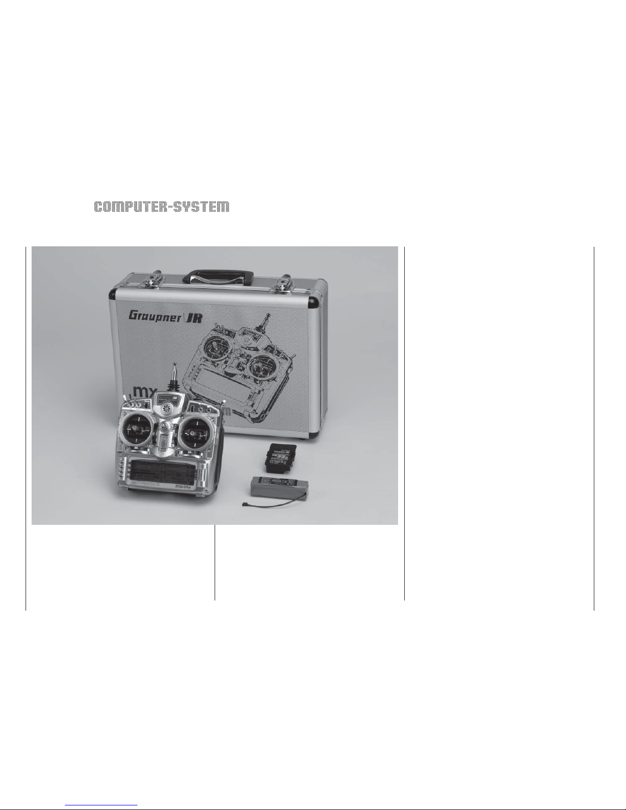
mx-24s micro-computer radio control system
Transmitter alone, with PLL Synthesizer RF module
and rechargeable transmitter battery installed, in aluminium case:
Order No. 4730.77 35/35B MHz band
Order No. 4748.77 40/41* MHz-Band
* 41 MHz band only approved for use in France.
Specifi cation – mx-24s transmitter
Transmission system Switchable: SPCM20, PCM20, PPM10,
PPM18, PPM 24, APCM24
Radio Frequency
section
Synthesizer (10 kHz spacing), 35 / 35B,
40 / 41 MHz band
Spot frequencies 35-MHz band: chan. 61-80, 281*, 282*
35-MHz-B band: channels 182 ... 191
40-MHz band: chan. 50 ... 59, 81 ... 92
41-MHz band: channels 400 ... 420**
Channel spacing 10 kHz
Max. control func-
tions
SPCM20 = 10, PCM20 = 10, APCM24 =
12, PPM10 = 5, PPM18 = 9, PPM24 =12
Control functions Four proportional functions with digi-
tal trims, two proportional functions, two
switched functions, two INC / DEC but-
tons
Channel pulse width 1,5 ms ± 0,5 ms
Control resolution SPCM20/APCM24: 10 Bit (1024 steps),
PCM20: 9 Bit (512 steps)
Aerial Telescopic aerial, ten sections, approx.
1150 mm long
Operating voltage 9,6 ... 12 V
Current drain approx. 85 mA (RF module removed)
150 mA (RF module switched off)
230 mA (RF module switched on)
250 mA (RF module and screen back-
light switched on)
Dimensions approx. 200 x 195 x 98 mm
Weight approx. 1100 g incl. transmitter battery
* Channels 281 and 282 not approved for use in Germany.
** 41 MHz band only approved for use in France.
* For charging the batteries you will also need the transmitter
charge lead, Order No. 3022.
** 12 V power source required.
Chargers and charge leads (optional accessories)
Order No. 6422 Minilader 2
Order No. 6427 Multilader 3
Order No. 6426 Multilader 6E*
Automatic battery chargers with special NiMH charge
programs:
Order No. 6419 Ultramat 5*, **
Order No. 6409 Ultramat 6*, **
Order No. 6410 Ultramat 10*,
Order No. 6412 Ultramat 12*, **
Order No. 6412.200 Ultramat 12*
Order No. 6414 Ultramat 14*,
Order No. 6417 Ultramat 25*, **
Order No. 6417.200 Ultramat 25*
Order No. 6416 Ultra Duo Plus 30*, **
Order No. 6425 Twin Charger
Please refer to the main GRAUPNER FS catalogue
for details of other battery chargers.
Recommended accessories
Order No. Description
70.25
Neckstrap (25 mm)
4178.1
Diagnosis lead
3290.22
Trainer / PC module
4182.9
PC interface lead
mc-22(s)/mx-22/mx-24s/PC
4185
USB PC interface
mc-22(s)/mx-22/mx-24s/PC
Replacement part
Order No. 3100.6 Telescopic transmitter aerial
Please refer to the Appendix and the main GRAUP-
NER FS catalogue for a detailed description of all
available accessories for the mx-24s radio control
set.
Description of radio control system
11
Page 12
12
Operating notes
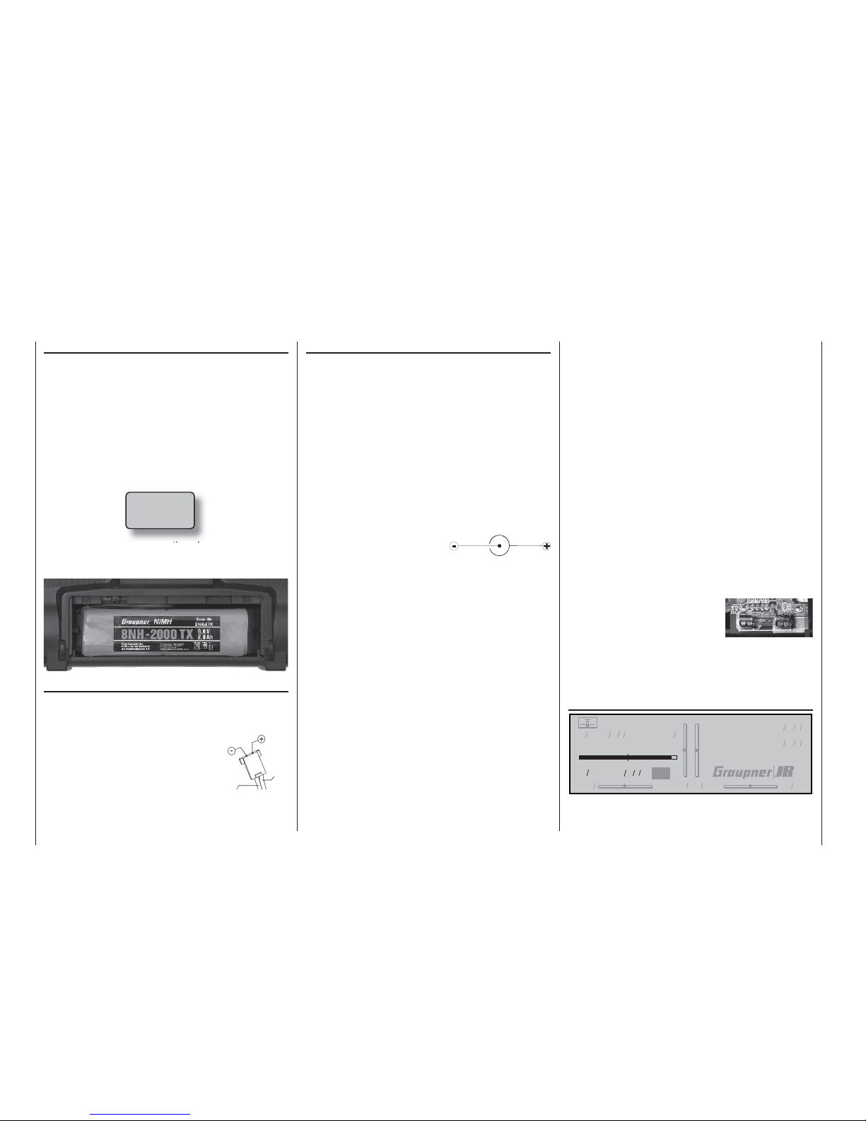
Transmitter power supply
The
mx-24s transmitter is fi tted as standard with a
9.6 Volt NiMH battery (8NH-2000TX) (specifi cation
may change). However, this battery is not charged
as supplied. When you are using the transmitter you
can monitor the battery voltage on the LCD screen.
If the voltage of the transmitter battery falls below a
certain point (see »General basic settings« menu
– page 154) you will hear an audible warning signal.
The screen then displays the following message to re-
mind you that the transmitter battery needs to be recharged:
If this happens, cease operations immediately; ideally the battery should be recharged before this level is
reached.
Removing the transmitter battery
To remove the transmitter battery fi rst remove the bat-
tery compartment cover on the rear face of the transmitter by sliding it in the direction of the arrow, then lift
it off. Carefully disconnect the connector at the main circuit board –
either pull gently on the cable or pull
out the plug with a fi ngernail, pulling
on the lug on the top of the connector. Don’t pull the plug up or down
when removing it; keep it parallel
with the circuit board.
Operating notes
Batt must
be re charged!!
Charging the transmitter battery
The rechargeable NiMH transmitter battery can be re-
charged via the charge socket fi tted to the right-hand
side of the case.
The transmitter must be switched off and left at “OFF”
for the whole period of the charge process. Never
switch the transmitter on when it is still connec-
ted to the charger; even a very brief interruption
in the charge process can cause the charge volta-
ge to rise to the point where the transmitter is im-
mediately damaged by the excess voltage. For this
reason check carefully that all connectors are secure
and are making really good contact.
Polarity of the
mx-24s charge socket
Commercially available battery charge leads produced
by other manufacturers are
often made up with reversed polarity. For this reason
use genuine GRAUPNER charge leads exclusively.
Caution: it is essential to connect the banana plugs
on the charge lead to the charger fi rst, and only then
to connect the other end of the lead to the charge
socket on the transmitter; this avoids the danger of
short-circuits. Never allow the bare ends of a connec-
ted charge lead to touch each other!
Charging the battery using a standard battery
charger
The basic rule for charging the battery using a stan-
dard charger, i. e. one without automatic charge termination, is to start with a discharged pack and charge it for fourteen hours at a current corresponding to
one tenth of the capacity printed on the label. In the
case of the standard transmitter battery this means
200 mA. It is up to you to terminate the charge process at the correct time.
Charging the transmitter battery using an automatic charger
The transmitter is designed as standard for use with
automatic battery chargers to recharge the transmitter pack.
If you wish to use an automatic charger designed for
NiCd batteries to recharge the NiMH pack which is fi tted to the transmitter as standard, please carry out
a series of test charges and check carefully that the
charger terminates the process correctly. If your charger provides a facility for adjusting the Delta Peak termination voltage, you may well need to adjust this value.
Maximum charge current
Do not exceed the maximum permissible charge current of 1.0 A, otherwise there is a danger of causing
damage to the transmitter.
Fuse: the transmitter is fi tted with a 20 mm cartridge
fuse (type: 3 Ampere, fast-blow). If the battery will not
accept a charge, or the transmitter cannot be switched on, please check this fuse (see “Opening the transmitter” on page
14). Never by-pass (bridge) the fuse. Replacement fuses can be obtained from any electrical supplies shop.
Ensure that the fuse is fi rmly and correctly seated;
you may need to bend the spring contacts slightly.
On-screen display of battery operating time
#01 0:00h SPCM20
10.9V
0:00h C62
0 0 0 0
Stop watch
Flight tim
000
000
:
:
This timer shows the cumulative operating time of the
transmitter since the last time the transmitter battery
Polarity of transmitter battery plug
brown or
black
red
Page 13
13
was charged.
This timer is automatically reset to “0:00” when the
transmitter battery voltage is signifi cantly higher than
the last time the unit was switched on, i. e. after a
charge process. This is the state shown in the screenshot.
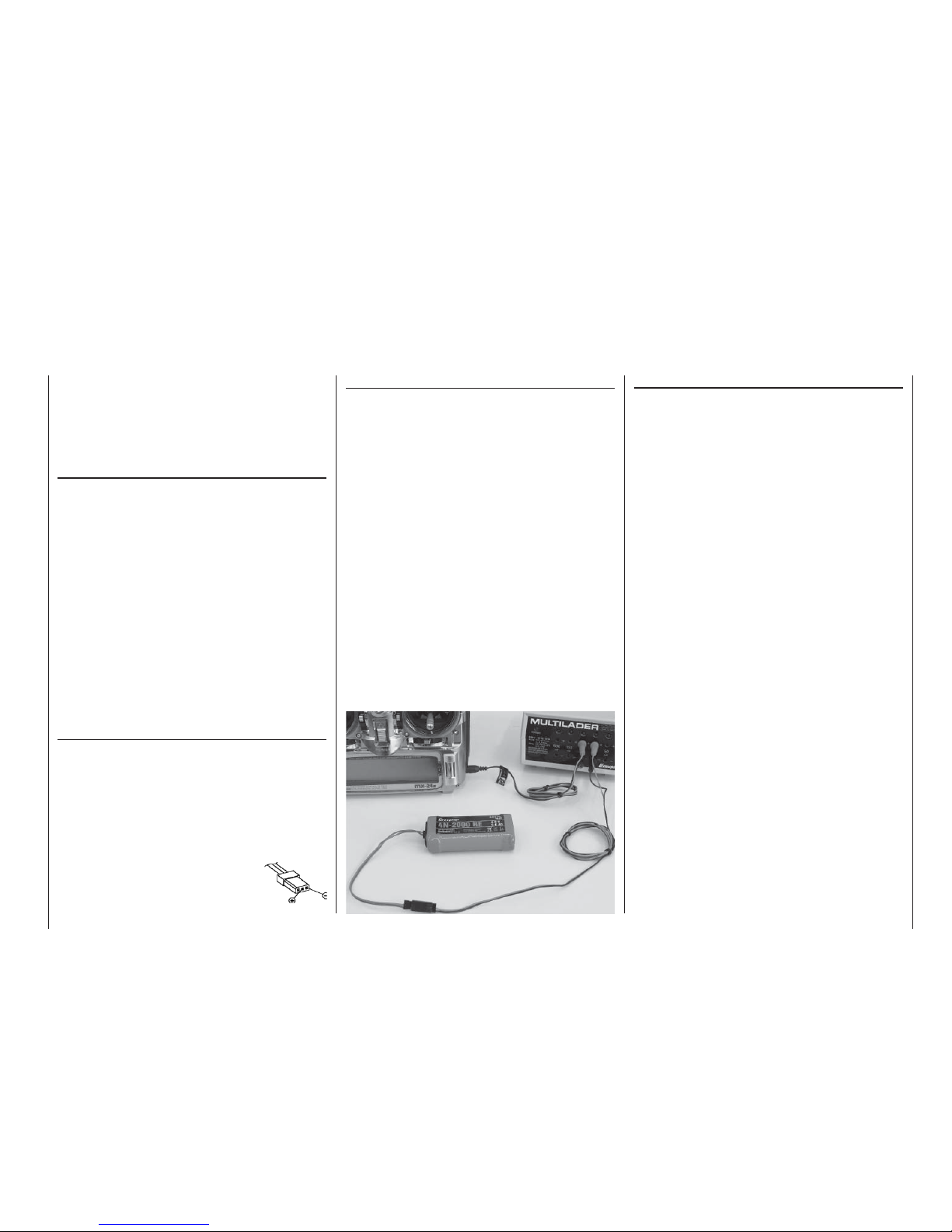
Receiver power supply
Various 4.8 V NiMH batteries are available for the re-
ceiver, varying in capacity. For reasons of safety you
should not use dry cells in model aircraft, helicopters
and other high-speed models. For the same reason
do not use individual cells fi tted in a battery holder;
always use ready-made battery packs with welded or
soldered connections.
There is no direct method of checking receiver battery
voltage when operating a model.
Make it a routine to check the state of your batteries
at regular intervals. Charge your batteries in good
time: don’t wait until you notice the servos running
more slowly than usual before recharging the pack.
Please refer to the main GRAUPNER FS catalogue
for full details of batteries, chargers, measuring
equipment and monitoring units for use with rechargeable batteries.
Charging the receiver battery
The charge lead, Order No. 3021, can be connected
directly to the receiver battery for charging. If the battery is installed in a model and you have fi tted one
of the following switch harnesses: Order No. 3046,
3050, 3934 or 3934.3, then the battery can be charged via the separate charge socket or the charge socket which is built into the switch. The switch on the
switch harness must be left at the “OFF” position for
charging.
Operating notes
General notes on battery charging
• Always connect the charge lead to the charger
fi rst, and only then to the receiver or transmitter
battery. This avoids the danger of accidental shortcircuit between the bare ends of the charge lead.
• Observe the recommendations provided by the
charger manufacturer and the battery manufacturer at all times. Keep to the recommended maximum charge current stated by the battery manufacturer. To avoid damage to the transmitter, the
charge current should never exceed 1.0 A; you
can usually limit the charge current on the battery
charger itself.
• Do not discharge the battery or carry out battery
maintenance programs via the integral charge socket, as the socket is not suitable for this application.
• Never leave batteries on charge unsupervised.
Disposal of dry cells and rechargeable batteries
Never dispose of exhausted batteries in the house-
hold rubbish. As end-user you are legally obliged
(“Battery Disposal Directive”) to return old and exhausted dry cells and rechargeable batteries to an
approved disposal centre, e. g. your local toxic waste
collection point or a retail outlet where batteries of the
same type are sold.
Polarity of receiver
battery connector
Page 14
14
Operating notes
Operating notes
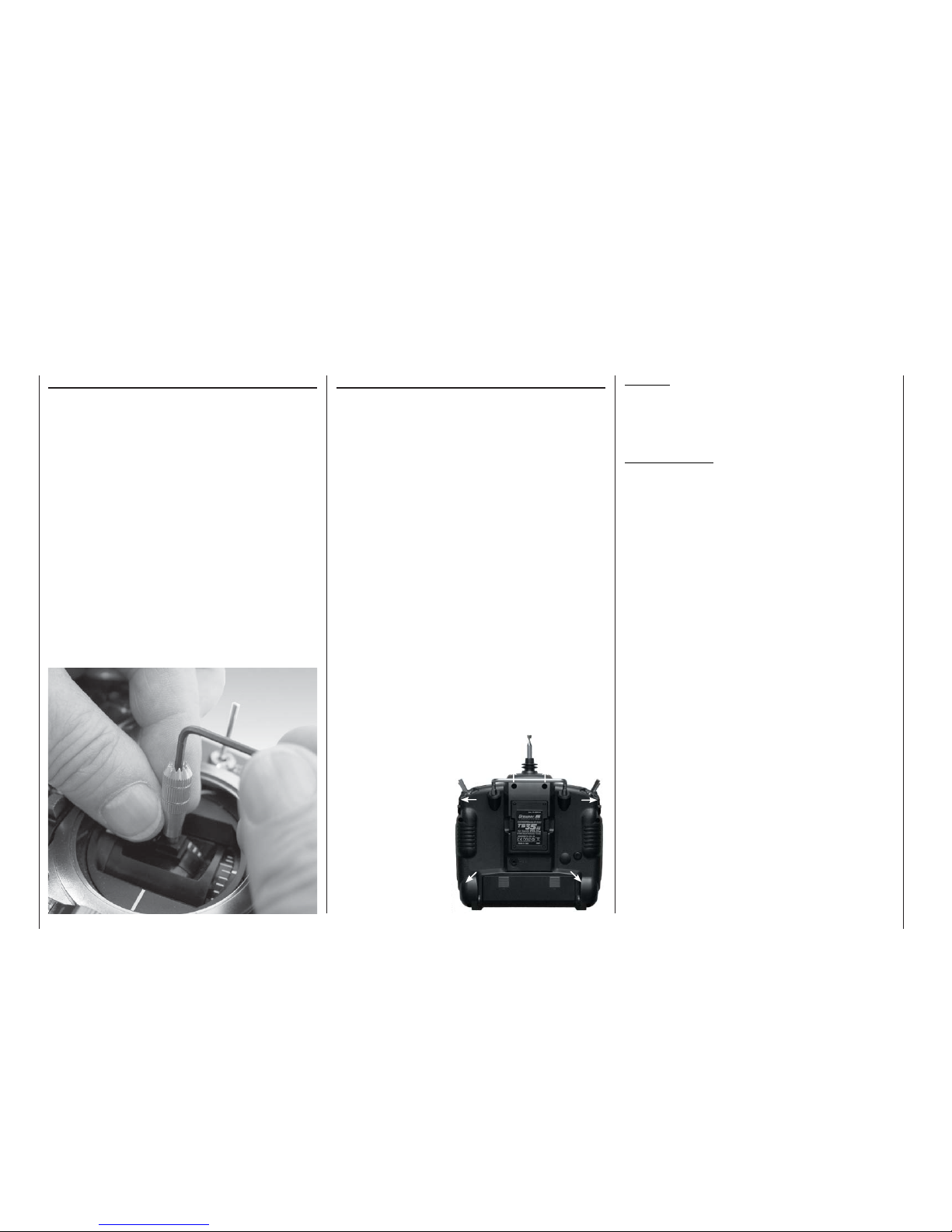
Adjusting stick length
Both sticks are infi nitely variable in length over a
broad range, enabling you to set them to the correct
length to suit your personal preference to provide fi ne,
accurate control of your models.
Loosen the retaining screw using a 2 mm allen key,
then screw the stick top in or out to shorten or extend
it. Carefully tighten the grubscrew again to lock the
set length.
Opening the transmitter case
Please read the following notes carefully before you
open the transmitter. If you are inexperienced in
such matters we recommend that you ask your local
GRAUPNER Service Centre to carry out these procedures for you.
The transmitter should only be opened in the following circumstances:
• In order to convert a non self-neutralising stick to
self-neutralising, or vice versa; see page 16;
• In order to adjust the stick centring tension;
• In order to replace the internal fuse (3 A, fast-blow);
• In order to install a “Trainer” system and data transfer system; see page 15 and page 204 of the Appendix.
Before opening the transmitter it is essential to check
that it is switched off (move the Power switch towards
the screen). It is not necessary to remove the transmitter battery, but if you do not remove it take care never to switch the transmitter on while the case is open
(“ON” position). Please see page 12 for information
on removing the transmitter battery. The RF module
can also be left in place.
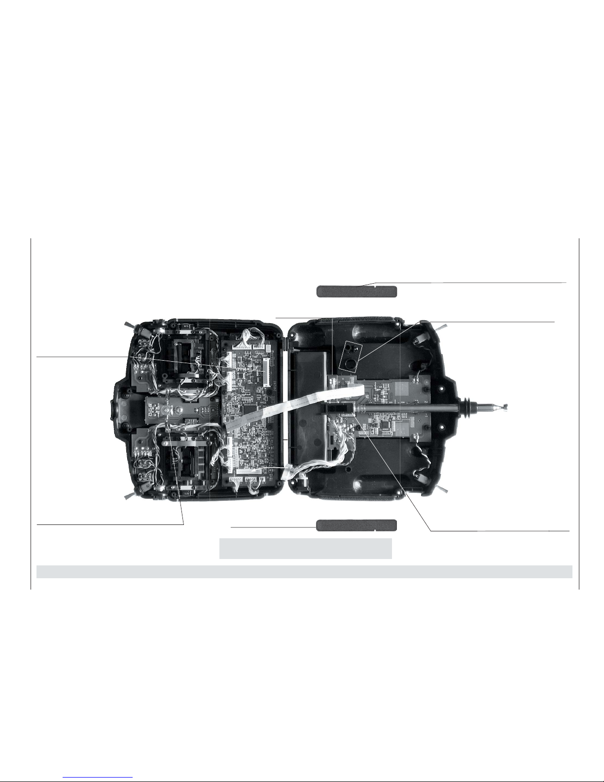
Use a cross-point screwdriver (size PH1) to undo the
six recessed screws
at the indicated
points in the rear
face of the transmitter. Hold the two
case shells together
with your hand, turn
the transmitter over
and allow the six
screws to fall out.
The back cover can
now be carefully removed.
Caution:
A loom of cables connects a circuit board in the
rear cover to the circuit board in the main case,
which means that the transmitter back cover can
only be folded down or to the side.
Important notes:
• Do not modify the transmitter circuit in any
way, as this invalidates your guarantee and also
invalidates offi cial approval for the system.
• On no account touch the circuit boards with
any metallic object, and do not touch the contacts with your fi ngers.
• Never switch the transmitter on when the case
is open.
When closing the transmitter please note the following points:
• Insert the two side-mounted proportional controls
correctly in the cut-outs designed for them in the sides of the transmitter case;
• You will fi nd two rubber pads fi tted loose in the sides; ensure that they are located with the small slot
facing the back cover, and engage them in the appropriate case cut-outs in the sides;
• Ensure that the wire loom connector between the
back cover and the circuit board is fi rmly inserted;
• Check that the V-shaped spring contacts (earth
contacts) in the centre of the transmitter are not
bent or deformed.
• Take care that no wires get caught when you close
the back.
• Ensure that the two case shells line up exactly
fl ush before you fi t the retaining screws. Never
force the case shells together.
Please refer to the illustration on the next page when
you carry out this procedure.
Page 15
15
Padding
If the two pieces of padding fall out when you open the transmitter, re-fi t them when closing the case, noting that the narrow slots face down in the case back, where they engage
over a small lug.
Operating notes
Side-mounted proportional controls
When re-assembling the transmitter check carefully that
the two side-mounted controls engage correctly in the cutouts designed for them in the top and bottom case shells.
On no account force the case shells together. All the other
switches are permanently installed.
Interface socket
14-pin socket for the optional Trainer / PC module, Order No. 3290.22, which is
available as an accessory
(see Appendix).
Earth contact spring
This spring completes the
earth connection to the cir cuit board in the case back
cover. Take great care not to
bend or deform these contacts.
If the ends of the spring appear to be dirty,
clean them gently with a soft, dry cloth.
Cartridge fuse
(3A, fast-blow)
Transmitter installation bays
The Trainer / PC module available as an
optional accessory (Order No. 3290.22) is
installed in these two bays; see Appendix.
Directing the telescopic aerial
Before using the transmitter to control a
model, screw the ten-section aerial
fi rmly into its socket and extend it
to its full length. However, never
point the aerial directly towards the
model, as signal strength is low in
an imaginary line extending straight out
from the aerial tip.
Aerial socket
Make sure that the aerial is fi rmly screwed
into the socket before using the transmitter.
Never switch the transmitter on when the
case is open.
C A U T I O N: on no account touch any soldered joint with a metal object: SHORT-CIRCUIT HAZARD. Such action invalidates your guarantee.
Padding (see top right)
Page 16
16
Operating notes
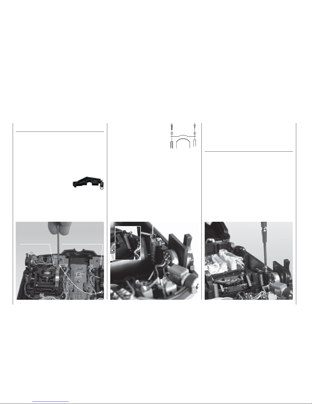
3. Attach the ratchet spring:
Attach the ratchet spring to
one end of the plastic pillar,
and set the desired spring
force by screwing the M3
screw in or out at the brass
stud.
4. If you wish to re-convert the
stick to self-neutralising action, fi rst remove the
ratchet spring and slightly loosen the centring
force adjustor screw: see right picture. Re-connect the neutralising lever, and slip a length of thin
thread through the top loop of the spring (don’t tie
a knot). Now use a pair of tweezers to connect the
bottom loop of the spring to the adjustment system (see close-up picture below). Finally connect
the top end of the spring to the neutralising lever
using the thread. Once the spring is in the correct
position, the thread can be withdrawn again.
The software also has to be “informed” of the change
in stick mode; this can be carried out separately for
each model in the »Base setup model« menu (pages 64 / 66). To set the stick mode for the transmitter
as a whole, i. e. so that it applies to all newly set-up
model memories, use the »General basic settings«
menu (page 154).
Stick centring force
The tension of the stick unit centring springs can be
adjusted to suit your personal preference: the adjustment system is located adjacent to each centring
spring.
Rotate the adjustment screw with a cross-point screwdriver to set your preferred spring force:
Turn to the right (clockwise) = spring force harder;
Turn to the left (anti-clockwise) = spring force softer.
Brass stud Plastic pillar
Changing the mode of the dual-axis proportional
stick units
Either stick can be converted from self-neutralising to
non self-neutralising (ratchet) action. First open the
transmitter as already described.
If you wish to switch the standard self-neutralising action to non self-neutralising, use this procedure:
1. Locate the brass stud supplied in the set, and
screw it to the left or right stick unit as required
using a 4 mm box spanner (see double arrow in
the picture below).
2. Use a pair of tweezers to disconnect the spring from the
neutralising arm of the appropriate stick unit, raise the lever
and disconnect this too.
Neutralising lever
and spring
Operating notes
Plastic
pillar
Brass stud
Ratchet
spring
Page 17
17
Operating notes
Changing the frequency band and spot frequency
The
mx-24s transmitter is fi tted as standard with a
PLL-SYNTHESIZER RF module. The spot frequency (channel) is selected using the rotary control, i. e.
plug-in crystals are no longer required at the transmitter.
The Synthesizer module also features an integral
dual-conversion frequency scanner which is used to
check whether your preferred channel is already in
use or not; it can also be employed to determine the
vacant channels on your particular frequency band.
A detailed description of the method of using the
Synthesizer module and selecting spot frequencies
is found on pages 24 and 25 in the section entitled
“Using the transmitter for the fi rst time – frequency
scanner and channel selection”.
The set spot frequency is displayed on-screen. A security system prevents the transmitter radiating an
RF signal when initially switched on. The RF module
must fi rst be activated in the software, which provides
an additional gain in safety.
At present two separate transmitters are available: for
the 35 / 35B MHz band and the 40 / 41 MHz band:
Transmitters alone:
Order No. 4730.77 for the 35 / 35B* MHz band
Order No. 4748.77 for the 40 / 41* MHz band
* Channels 281 and 282 on the 35 MHz band, and all channels
on the 41 MHz band, are not approved for use in Germany; see
also the Frequency Table on page 206. The same table shows
which channels are approved for use with the various types of
model, i. e. model aircraft, model boats and RC cars.
The channels approved for use in individual countries
are shown in the Frequency Table on page 206 (information not guaranteed).
The receiver must be operated on the same channel
and the same frequency band as the transmitter.
It is possible to use this transmitter to control any
GRAUPNER PLL Synthesizer receiver as well as ear-
lier crystal-controlled GRAUPNER receivers, provided
that they are compatible with the transmitter modes
PCM20, SPCM20, PPM18 or PPM24.
If you wish to use earlier crystal-controlled GRAUP-
NER receivers, it is essential to use genuine GRAUPNER FMsss plug-in crystals designed for the appro-
priate frequency band (see page 206). The receiver
crystal is marked “R” (Receiver), and should be inserted fi rmly into the opening in the receiver.
Important note:
The RF Synthesizer module is connected to the
mx-
24s transmitter by means of two sockets. If the RF
module is not plugged in correctly, the transmitter will
switch directly to the basic display when switched on.
The screen will then display the fl ashing message
“C––” instead of a channel number, indicating that the
RF module is not ready for use.
#01 0:00h SPCM20
10.9V
0:05h C--
0 0 0 0
Stop watch
Flight tim
000
000
:
:
Changing the frequency band
If you wish to switch from the 35 / 35B MHz band to
the 40 / 41 MHz band or vice versa, all you have to
do is replace the SYNTHESIZER RF module in the
transmitter:
Order No. 3853.35 for the 35 / 35B MHz band
Order No. 3853.40 for the 40 / 41 MHz band
Page 18

18
Operating notes
DSC socket
Direct Servo Control
Model name
#01 0:30h SPCM20
H-J.Sandbrunner
10.2V
0:30h
0000
Stop watch
Flight tim
000
000
:
:
DSC
3. Connect the other end of the connecting lead to
the desired device, taking into account the operating instructions supplied with that equipment.
4. If you wish to use the Diagnosis lead, Order No.
4178.1, do not connect it directly to the receiver.
First connect the lead to a receiver battery using a
Y-lead (3936.11 or 3936.32), then connect this to
the receiver’s battery input socket instead of the
receiver battery. The end with the barrel plug can
then be connected to the appropriate socket on
the back of the transmitter.
Once the transmitter is connected to the recei-
ver as described above, you can check the control functions or make changes to settings even
if another pilot is using “your” frequency. Since in
this state (power = “OFF”) the transmitter does
not broadcast a radio signal, you can, for example, prepare your model ready to fl y without causing
interference to other modellers. Another advantage is that the transmitter’s current drain is reduced, since the transmitter’s RF section is not active in this mode of operation. The use of Diagnosis
mode therefore extends the operating time of the
transmitter battery considerably.
Important:
Ensure that all the cables are fi rmly plugged in.
Note regarding fl ight simulators:
The range of fl ight simulators available commercially is now very wide, and you may fi nd that it is necessary to swap over the contacts at the barrel plug or
the DSC module. This work must be carried out by a
The original function of this socket was for “Direct
Servo Control”, and that’s why the abbreviation is still
in use. However, it is now much more versatile than
simply providing a means of controlling servos by cable. The two-pole DSC socket of the mx-24s is now
also used as the Teacher or Pupil socket in a Trainer
system (see page 150), and as an interface for fl ight
simulators.
For the DSC connection to work you must check
the following:
1. Carry out any adjustments required in the appropriate menus:
If you are connecting the transmitter to a fl ight si-
mulator, or if you are using the mx-24s transmitter as a Pupil transmitter in a Trainer system, then
you must set the transmission mode to “PPM18” in
the “Modulation” line of the »Base setup model«
menu. However, if you wish to connect a Diagnosis
lead (Order No. 4178.1), the “Modulation” must
be selected to suit the receiver.
2. Always leave the transmitter’s On / Off switch
in the “OFF” position in such cases, because
otherwise the RF section of the transmitter module
will not be switched off (no RF signal) even when
the DSC lead is plugged in. This is particularly important if you are using a Diagnosis lead or a Trainer lead, because your transmitter may otherwise
cause interference to other pilots. Only when the
mx-24s transmitter is in Teacher mode should the
transmitter be switched on before the Trainer lead
is connected (see page 150).
Connect the appropriate two-pole lead to the
transmitter’s DSC socket. This action renders the
transmitter and the LCD screen ready for use, circumventing the channel select process. At the
same time the screen shows the message “DSC”
instead of the usual display of the selected transmission channel.
GRAUPNER Service Centre.
Caution:
Certain receivers – such as the R16SCAN – feature a battery socket to which a servo can also be
connected via a Y-lead. It is not possible to use a
DSC lead with this type of receiver.
Page 19

19
For your notes
Page 20
20
Description of transmitter
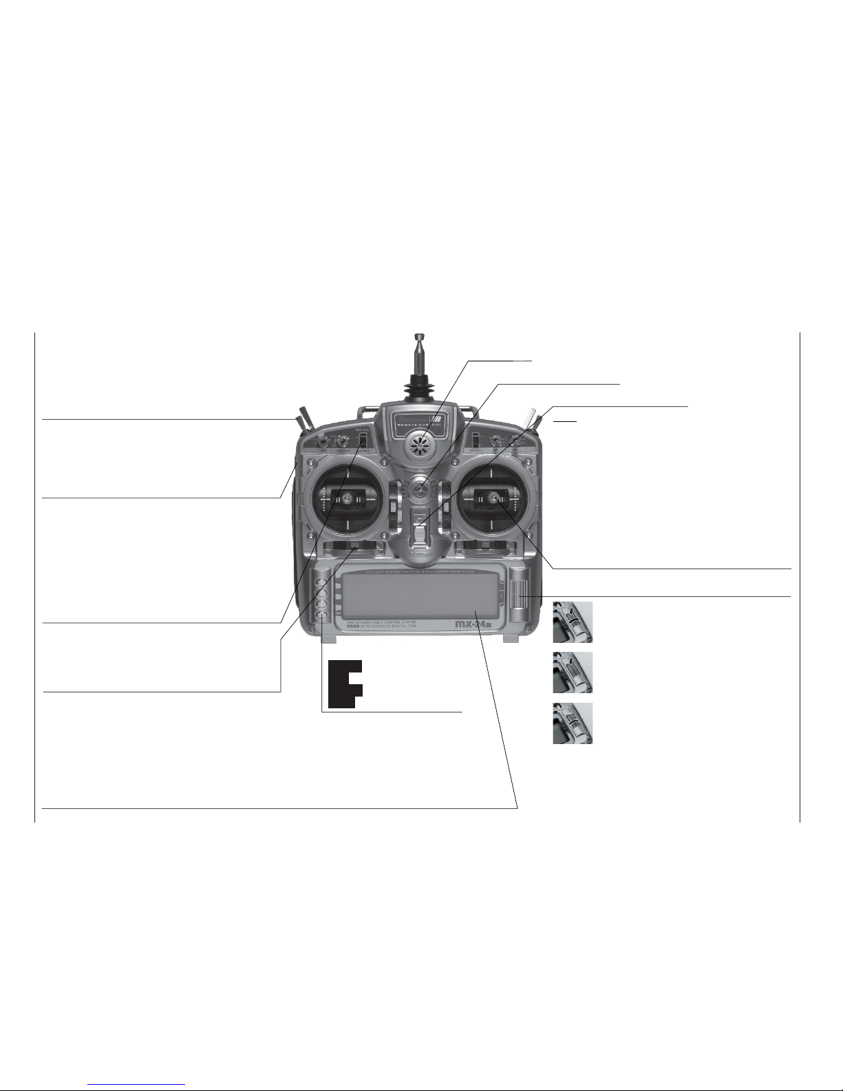
Transmitter aerial
(ten-section
telescopic)
Piezo buzzer
Proportional controls
Two proportional controls are mounted on the sides
of the transmitter as standard. A centre detent ensures reproducible centre settings. In this case they are
described in the corresponding menus as : right-hand
control “CTRL 9”, left-hand control “CTRL 10”.
Operating buttons:
ENTER Input button
ESC Back button
CLEAR Erase button
HELP Help button
LCD screen (see page 22 for more details)
The thin protective fi lm over the screen surface can be peeled off using your fi ngers if you wish.
Contrast adjustment: from the basic display press the rotary control and rotate it at the same time; al-
ternatively press the rotary control and press the CONTROL 5 or 6 buttons, if these are not already in
use for other purposes.
Warning indicators : If battery voltage falls below the set threshold • if there is a Trainer system malfunction • if Channel 1 is too close to full-throttle when the transmitter is switched on • if the Fail-Safe
settings are not correct • power-on warning (checking a switch position).
ON / OFF switch
Note:
Always switch the transmitter on fi rst, followed
by the receiver. After a fl ight: switch the receiver off fi rst, followed by the transmitter.
Rotary control, providing two-level control
Description of transmitter
Front panel
Switches between individual lines within a menu when
held pressed in. When held pressed in turn the rotary
control at the top end of the cylinder for a better grip.
A brief press on the top end of the rotary control changes the input fi eld, or confi rms your input. Pressing the
HELP button with the rotary control held pressed in
switches directly to the »Servo display« menu from
the basic display and most menus.
If rotated in its normal (non-pressed) state, the rotary control selects your chosen item from the list in the
multi-function menu. Once you have called up a menu
point, the rotary control also changes the entered value in a highlighted fi eld (light characters on dark background) which appears at the bottom edge of the
screen. Any alterations you make take effect immediately. When not pressed in, turn the rotary control at the
bottom end of the cylinder for a better grip.
Transmitter neckstrap lug
Digital trims
For fi ne adjustment of servo (travel neutral) position.
A brief push produces a single increment of offset
(the increment size is variable in the “Stick mode”
menu). The screen displays the trim positions.
Increment / Decrement buttons
Two proportional controls as standard: every time the
button is pressed, the travel of the associated servo changes by 1% relative to the pre-set servo travel.
INC = positive direction, DEC = negative direction.
These controls are numbered as follows: right-hand
button “CTRL 5”, left-hand button “CTRL 6”. These
two buttons can be used as an alternative to the rotary control if they are not already in use for other purposes.
Stick units
Two dual-axis stick units providing four independent
control functions. Variable-length sticks. The control
functions (i. e. stick mode) can be assigned within the
“Base setup model” menu, e. g. throttle left or right.
The throttle stick can also be set to be self-neutralising or ratchet action: see page 16.
Switches
Eight external switches as standard (SW = switch), of which
two-position: SW 1, 2, 3, 4, 7, 8 (switch 8: self-neutralising)
three-position: SW 5 + 6, 9 + 10. The three-position switches are
also used as transmitter controls to provide three-position servo travels. In this case they are described in the corresponding menus as :
right-hand switch “CTRL 7”, left-hand switch “CTRL 8”.
Page 21
21
1
23
4
56
Description of transmitter
Note:
If you intend to work on the interior of the transmitter, remember not to switch the transmitter on.
Disconnect the transmitter battery from the power socket. Take great care not to touch soldered
joints with any metallic object.
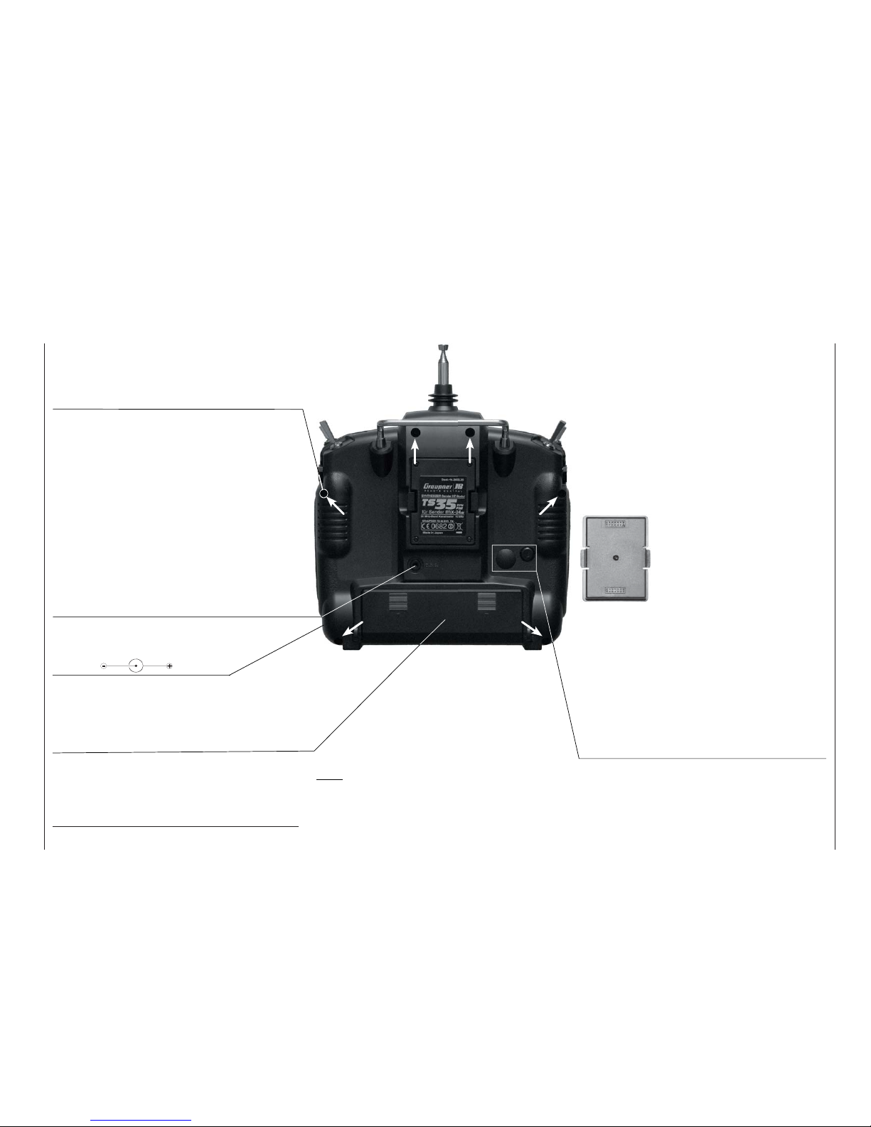
Back panel
Opening the transmitter case
Undo the six recessed screws in the rear face of
the transmitter using a cross-point screwdriver (size
PH1). Be sure to read the section on page 16 before
you proceed!
Synthesizer RF and Scan Module
The frequency band can be changed quickly and easily by carefully withdrawing the RF module using the
two side-mounted lugs. Note: plug-in crystals are not
necessary due to the PLL Synthesizer technology
employed in the transmitter.
The channel is selected under software control immediately after you switch the transmitter on; see page
25. The new form of DUAL-CONVERSION scanning
receiver is an integral part of the RF module. This enables you to check which channels in the vicinity of
the transmitter are already in use; see page 24.
When you re-install the module, ensure that the contact pins are not bent.
Charge socket
Please read the notes on battery charging
on pages 12 … 13.
Polarity:
Diagnosis socket (DSC*)
A special lead is available under Order No. 4178.1
which connects the mx-24s transmitter directly to
a suitable receiver. If the transmitter is switched off,
plugging the lead in automatically switches it on. At
the same time the RF module remains disabled, with
the result that no signal is transmitted via the aerial.
The DSC socket can also be used as a Teacher or
Pupil socket in a Trainer system; for more details please refer to page 18 and the description of the »Tea-
cher / pupil« menu on page 150.
Teacher / PC module, Order No. 3290.22
An optional module is available which converts the
mx-24s transmitter into an opto-electronic Teacher
unit for use in a Trainer system. For Trainer mode operations you will also need to connect a light-pipe (optical cable) to the appropriate socket on the transmitter;
this is available as an optional accessory. The second
socket on the module is for data transfer between two
mx-24s transmitters, or between an mx-24s and a
PC. The accessories required for this are also listed in
the Appendix.
Battery compartment
If you need to remove the battery, press on the two
corrugated areas with both thumbs, then slide the
battery compartment cover in the direction of the arrow.
* DSC = Direct Servo Control
SYNTHESIZER transmitter RF mo-
SYNTHESIZER transmitter RF mo-
dules for the
dules for the
mx
mx
-24s transmitter
-24s transmitter
Order No.
Order No.
3853.35
3853.35
35 MHz band
35 MHz band
Order No.
Order No.
3853.40
3853.40
40/41 MHz band
40/41 MHz band
Page 22
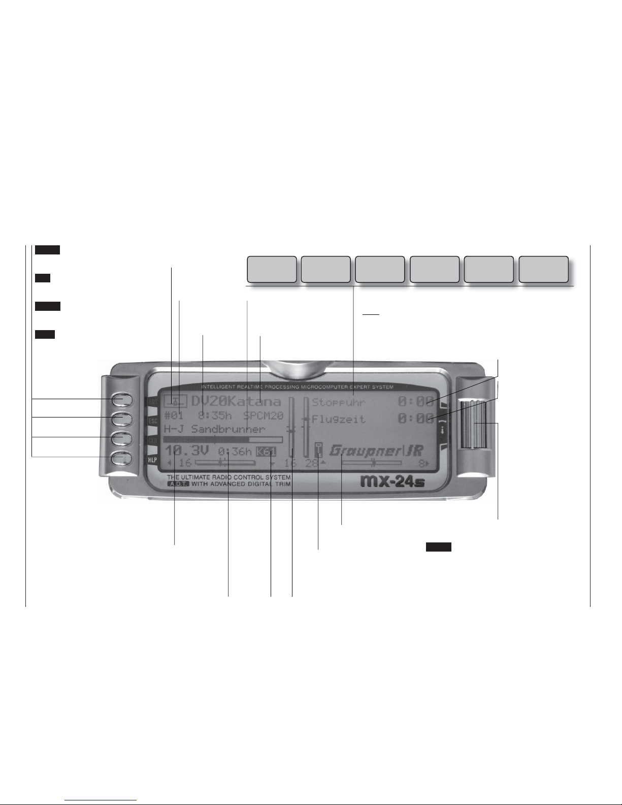
22
Description of screen
ENTER (Input button):
Switches to multi-function list
Calls up a menu
ESC (Escape button):
Returns step by step from any
menu to the basic display
CLEAR (Erase button):
Resets altered values to default
settings
HELP (Help button):
Calls up a brief help message relating to any menu
Model name
(max. 10 characters)
Model memory
1 … 40
User’s name
(max. 15 characters)
Model operating time
Superimposed warning messages*
Stopwatch in min:sec
(count-up / count-down)
Flight time in min:sec
(count-up / count-down)
Battery voltage, shown by a dynamic bar
display. If the battery voltage falls below a
particular (selectable) threshold (see page
155), a warning appears on the screen accompanied by an audible alert signal.
Transmit-
ter operating
time. This is
automatically
reset to zero
when the bat-
tery is rechar-
ged.
Display diagram for all four digital trim levers with numerical and direction indicators: “
”
or “”. Special cut-off trim for C1 (see page 34).
For each trim lever separately the “shadow” indicates whether the trim operates glo-
bally (= shadow) or separately for each fl ight phase (this parameter is set in the »Stick
mode« menu, see pages 76 / 77). Exception: the C1 trim always operates globally.
The rotary control can be
operated on two levels.
At the basic transmitter
display it is used to adjust screen contrast when
held pressed in, or:
Press the rotary control
and adjust screen contrast using CTRL 5 or 6 –
unless these buttons are
already assigned to another function.
GRAUPNER logo, alternatively the fl ight phase name. Different fl ight phases are selected
by operating user-assigned switches.
Description of screen
Batt must
be re charged!!
Charge battery*
Current
channel
number.
The num-
ber fl as-
hes if the
RF module
is switched
off.
(Note: an additional timer
can also be activated.)
Model type
Fixed-wing or
Helicopter
Notes:
* If the transmitter battery voltage is too low, the message “Currently not possible,
battery voltage too low” appears in the »Model select« and »Copy / Erase« menus.
** For safety reasons this warning can only be disabled for non-powered fi xed-wing
models: in this case select the »Model type« menu (see page 70) and enter
“none” in the “Motor” line.
Unlock by
rotary
and CLR
Button pad lock
Button pad lock
Hold rotary control pressed in + CLEAR button.
Thr
too
high!
Throttle stick too
advanced**
No
pupil
signal
Problem with
Trainer mode
Fail Safe
setup
t.b.d.
Only in PCM20,
SPCM20 and
APCM24 modes
!Warning!
Power-on war-
ning for selectab-
le switch
Page 23

23
Using the transmitter for the fi rst time
Using the transmitter for the fi rst time
Preliminary notes, selecting the language
Preliminary notes
When your
mx-24s transmitter is delivered it is set
by default to SPCM20 mode, which suits receivers
of the “smc” type.
In addition to SPCM-20 mode the following alternative modes are also available:
• PCM20 mode for all GRAUPNER/JR “mc” and “DS
mc” type receivers.
• PPM18 mode for all GRAUPNER/JR “FM-PPM”
type receivers.
• PPM24 mode for the GRAUPNER/JR DS 24 FM S
receiver.
• PPM10 mode for GRAUPNER/JR FM receivers
with up to five servo outputs, e. g. SR6SYN or
XP10FM.
• APCM20 mode for all GRAUPNER/JR “amc” type
receivers.
The ability to switch transmission modes means that
the mx-24s transmitter can operate all GRAUPNER
receiving systems supplied to date, i. e. all receivers
supplied with PPM-FM and PCM transmitters (with
the exception of the FM6014 / PCM18).
If you do not intend using a receiver of the “smc” type
with the transmitter, the fi rst step is therefore to set
the type of modulation to suit your receiver. If you select an incompatible mode, the receiver will not respond to the transmitter.
The transmission mode can be set in the “Modulation” line of the »Base setup model« menu, and the
as signment of the four stick functions in the “Stick
mode” line (see pages 64 and 66) for the current model memory, or in the »General basic settings«
menu (description: page 154) for all future model memories.
Which crystals can be used?
The mx-24s requires no plug-in crystals. The transmission channel is selected by software: see the following page.
Is the battery charged?
When you take receipt of your mx-24s transmitter, the battery will be in the discharged state, so you
must fi rst charge it as described on pages 12 … 13. If
you do not do this, the battery will soon fall below the
pre-set threshold voltage, and you will see and hear
a warning signal to remind you to recharge it. The low
voltage threshold can be set to
any value in the range 9.3 to 11.0
V in the “Battery Warning Threshold” line of the »General basic
settings« menu. The default setting is 9.3 V.
Aerial fi tted?
Never switch the transmitter on unless the aeri-
al is screwed in. Even for prolonged testing you
should always fi t the aerial and extend it fully,
otherwise the transmitter may malfunction, with possible damage to the RF module.
When you wish to control a model it is fundamentally essential to screw the ten-section telescopic aerial into the transmitter and extend it fully.
Transmitter fi eld strength is at a minimum in an imaginary line extending straight out from the tip of the
transmitter aerial. It is therefore fundamentally misguided to “point” the transmitter aerial at the model with
the intention of obtaining good reception.
Selecting the language
The
mx-24s allows you to select any of the following
four languages:
• German
• English
• French
• Italian
The language is selected by holding the HELP button
pressed in while you switch the transmitter on; the following display appears:
D
GB F I
The rotary control can now be used to select the desired language. Confi rm your choice with a brief press
on the rotary control, or by pressing the ENTER button.
All settings are retained in full if you switch to a
different language.
Batt must
be re charged!!
Page 24
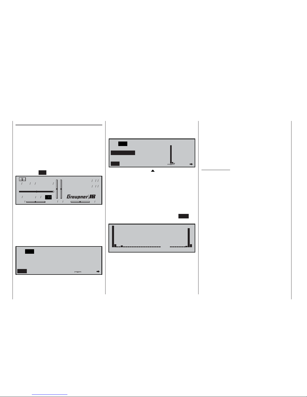
24
Using the system for the fi rst time
Frequency Scanner and Channel Select
Frequency scanner
The SYNTHESIZER RF module is equipped with a
dual-conversion frequency scanner. This module enables the user to scan the vicinity for occupied channels on the frequency band of your RF module before
it is activated.
Before you switch the transmitter on, please check
that the SYNTHESIZER module is fi rmly seated in
the back of the transmitter. If this is not the case, the
transmitter will switch directly to the basic display
when switched on, and the screen will show the fl ashing display “C– –” instead of a channel number.
Model name
#01 0:30h SPCM20
H-J.Sandbrunner
10.9V
0:10h C
0 0 0 0
Stop watch
Flight tim
000
000
:
:
For safety reasons, every time you switch the transmitter on you must fi rst confi rm to the integral Synthesizer module that you wish to use the set frequency. This confi rmation takes the form of a security query, intended to prevent you switching the system on
accidentally when it is set to the wrong channel. The
software displays the message: “RF off / on”. The last
set channel is initially highlighted (highlighted = black
background) and fl ashes:
C61
RF off
SCAN
---
NO
switch on
YES
Channel
The integral scanner immediately searches all channels on the current frequency band, regardless of
the set channel. If another transmitter is already active on the pre-set channel – in this case “61” – a mes-
sage appears on the screen to alert you, and at the
same time the internal piezo sounder emits a warning
sound. The current signal strength is indicated by an
on-screen bar diagram:
C61
RF off
NO SCAN
IN USE !!
Channelswitch on
YES
In the centre – above the “ ” symbol – the signal
strength of the currently set channel is displayed, to
right and left of it the signals present on the two adjacent channels.
(In our example channel 61 is the lowest channel in
the 35 MHz band, so no signal bar is displayed to the
left of it.)
In our example it is clear that channel 61 is already
in use. This means that you must search for another
unoccupied channel before activating the RF module. This is accomplished by switching to the SCAN
screen page using the rotary control:
---------------------- ----------
61 65 70 75 80 182 186 191
On this screen you will see a list of all the channels
which are accessible using the RF module currently installed in the transmitter. The scanner automatically and repeatedly searches the frequency band for
further signals.
In this example we can see that channel “190” is also
in use in addition to channel “61”. The signifi cantly
weaker signals – in this case on channels 62, 65, 189
and 191 – may be due to a variety of sources, such
as weak signals from very distant radio control systems, or crosstalk effects from radio control systems
in the immediate vicinity. If you think this might be the
case, walk a few metres away from the other radio
control transmitters, and observe whether the signal
strength diminishes rapidly with increasing distance.
Under certain circumstances, especially when other
transmitters are very close by, what seem to be “unaccountable signals” may be displayed on other channels.
Important notes:
• Please note that it is possible to switch the RF
module on even if the message “IN USE !!” appears on the screen. However, if you do switch
on, then you will endanger your own model
as well as the models of other pilots due to a
channel clash (two transmitters on the same
frequency).
• The range of the mx-24s scanner is limited,
which means that it may not always detect the
signals from relatively distant radio control
transmitters. You should therefore not rely on
the scanner picking up signals from other model pilots if they are standing some way off;
this applies in particular if the terrain is uneven
and line-of-sight contact is limited.
• The indicated signal strength of other radio
control system transmitters depends to a considerable extent on the conditions prevailing
at the model fl ying site, and also on the transmitted power and aerial length of other transmitters, the distance between the mx-24s and
other transmitters, and the direction of the mx24s aerial relative to other transmitter aerials.
The sensitivity of the integral scanner also varies according to the extent to which the mx-24s
transmitter aerial is extended.
• At present channel 80 is followed by channels
281 and 282, which are not approved for use in
Using the system for the fi rst time
Page 25
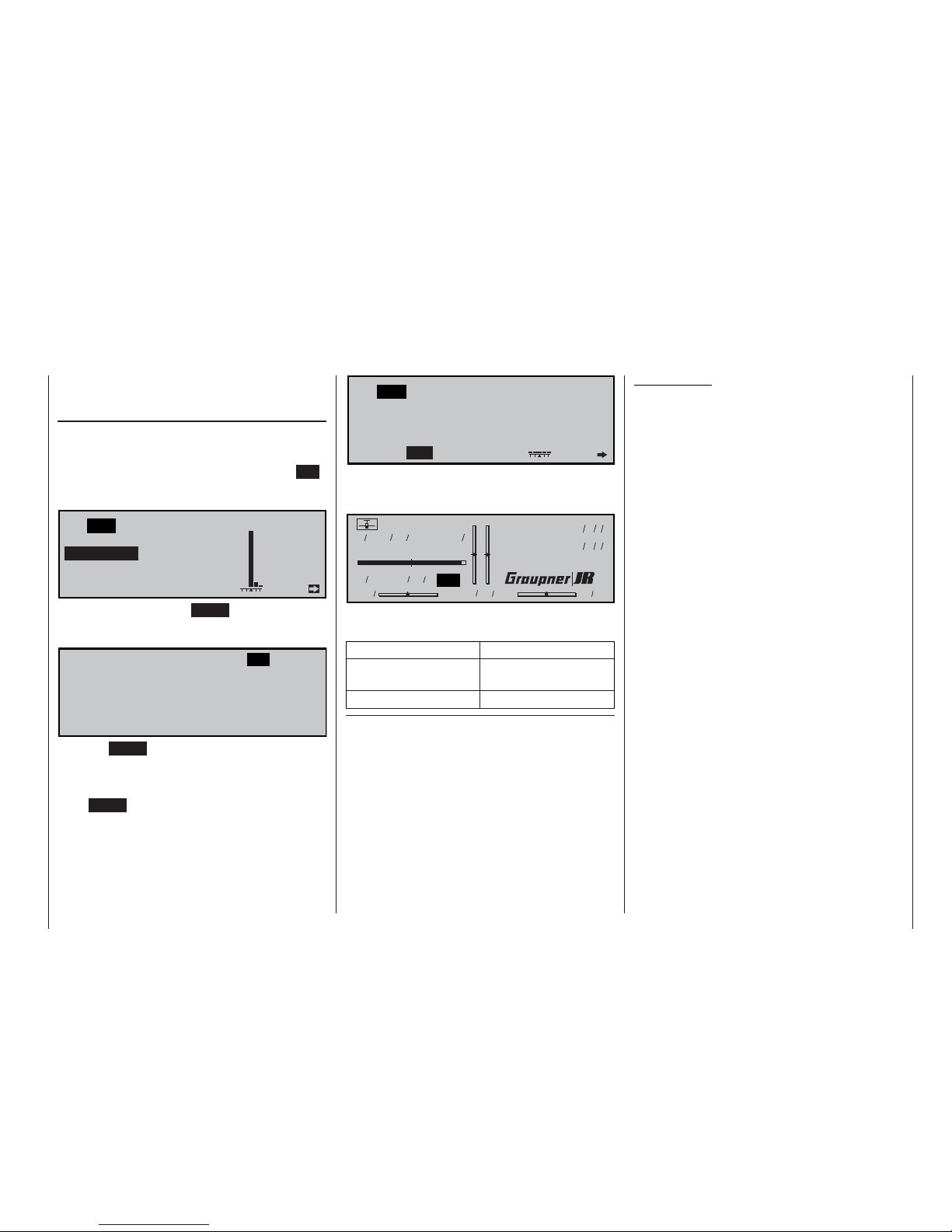
25
Using the system for the fi rst time
Germany; see the channel select list in the next
column.
Selecting the channel
Select a vacant spot frequency, e.g. (in this case)
channel 65, after establishing that the low-level signal
indicated on the display is only due to crosstalk effects from a transmitter in the vicinity. Press the ESC
button to return to the previous screen display, and
switch to Channel Select “” using the rotary control:
C61
RF off
NO SCAN
IN USE !!
Channel
YES
switch on
Press the rotary control or ENTER, then select the
desired channel – in this case 65 – from the list using
the rotary control:
C61 C65 C66
C67
C73
C79
C184
C190
C62 C63 C64
C68 C69 C70 C71 C72
C74 C75 C76 C77 C78
C80 C281 C282 C182 C183
C185 C186 C187 C188 C189
C191
Press the ENTER button or the rotary control to terminate the channel select process.
If you now wish to activate the RF module with this
channel, use the rotary control to move to “YES” and
press ENTER (or press the rotary control briefl y); this
action switches on the RF module on the new channel:
C65
RF off
NO
YES SCAN
Channelswitch on
The screen immediately switches to the basic display,
which now shows the number of the active channel in
highlighted form:
Model name
#01 0:30h SPCM20
H-J.Sandbrunner
10.9V
0:10h C65
0 0 0 0
Stop watch
Flight tim
000
000
:
:
The transmitter is now ready for use.
The following channels are available:
Frequency band Channels*
35/35B MHz band 61 … 80 / 281, 282
also 182 … 191
40/41 MHz band 50… 92 / 400 … 420
* Channels 281 and 282 in the 35 MHz band, and all channels in
the 41 MHz band, are not approved for use in Germany. Please
refer to the frequency table on page 206, which lists the channels valid in the European continent at time of going to press
(information not guaranteed).
You must now switch the transmitter off, then on
again, in order actually to switch to another channel.
The basic procedure for the initial programming of a
new model memory is described on page 58, and in
the section starting on page 158 in the programming
examples.
W A R N I N G:
NEVER, UNDER ANY CIRCUMSTANCES, SWITCH
THE TRANSMITTER OFF WHEN YOU ARE FLYING
A MODEL AIRCRAFT! IF YOU DO, YOU RUN A SERIOUS RISK OF LOSING THE MODEL, AS YOU
WILL BE HIGHLY UNLIKELY TO BE ABLE TO REACTIVATE THE RF SIGNAL QUICKLY ENOUGH
WHEN YOU SWITCH ON AGAIN, SINCE THE
TRANSMITTER ALWAYS RESPONDS WITH THE
SECURITY QUERY “RF SIGNAL ON YES / NO”
WHEN SWITCHED ON.
Page 26
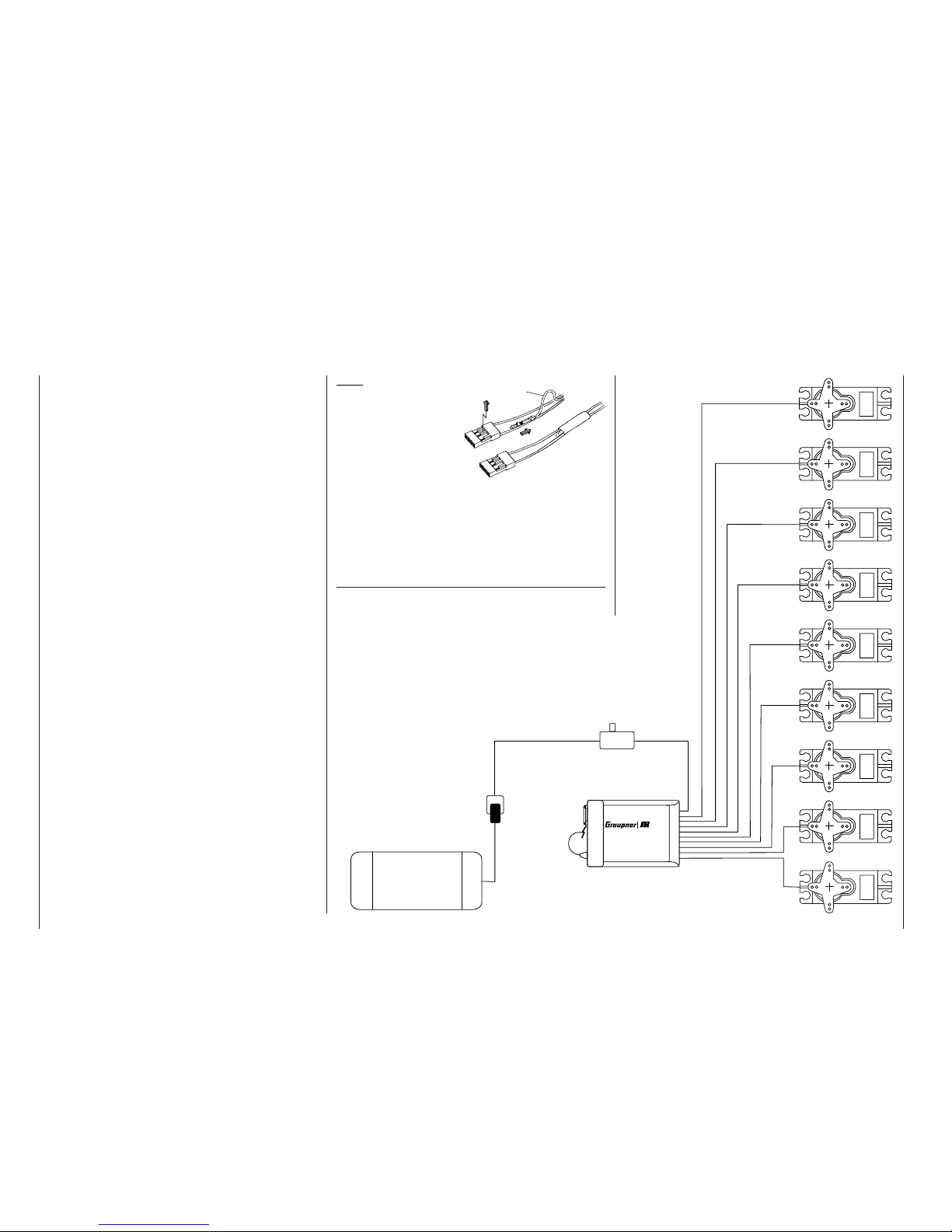
26
Batt.
Servos
1
2345678 9
Installation notes
Note:
If you wish to use a receiver battery and a
speed controller with
integral BEC* system
simultaneously, it is
usually necessary to
disconnect the positive (red) wire from the
3-pin plug. This varies from controller to controller, so
please read the instructions supplied with the unit.
Use a small screwdriver carefully to raise the centre
lug of the plug (1), withdraw the red wire (2) and wrap
the exposed contact with insulating tape to prevent
possible short-circuits (3).
*Battery Elimination Circuit
Please read the installation notes relating to the receiver, the receiver aerial, and the servos on the following page.
If the receiver is of the type requiring an interchangeable plug-in crystal, the channel number of the receiver must be identical to the channel number set on
the transmitter. In this case it is only permissible to
use the plug-in crystals marked “R” (for Receiver) as
shown in the table on page 206. No receiver crystal
is required if you are using a GRAUPNER PLL Synthesizer receiver. According to the receiver type, the
desired channel number is set either directly on the
receiver using the channel selector, or by means of a
frequency scan; see the instructions supplied with the
receiver.
GRAUPNER receivers are fi tted with polarised sockets, so that the servos and power supply cannot be
connected the wrong way round; you will fi nd that the
plugs are slightly chamfered on one edge to match
the sockets. Connect the battery to an ON / OFF
switch harness (see the main GRAUPNER FS catalogue), and connect the switch to the socket on the
receiver marked “Batt”.
If you use the DS 24 FM S or amc24DSCAN receiver you can control up to twelve servos, speed controllers etc. directly. Servos 1 to 12 can be controlled
using the two dual-axis sticks and – after appropriate programming – any other (proportional) controls or
switches present on the
mx-24s transmitter. The two
latter types of controls can be assigned to inputs 5 …
12 in the software; see the »Transmitter control ad-
just« menu, pages 78 / 80. However, all servos can
also be accessed via mixer functions; see the »Free
mixers« menu on page 135.
1
2
3
red
Receiving system
(not included in the set)
Receiver
Receiver
battery
battery
receiver
Aerial
Switch harness
Page 27
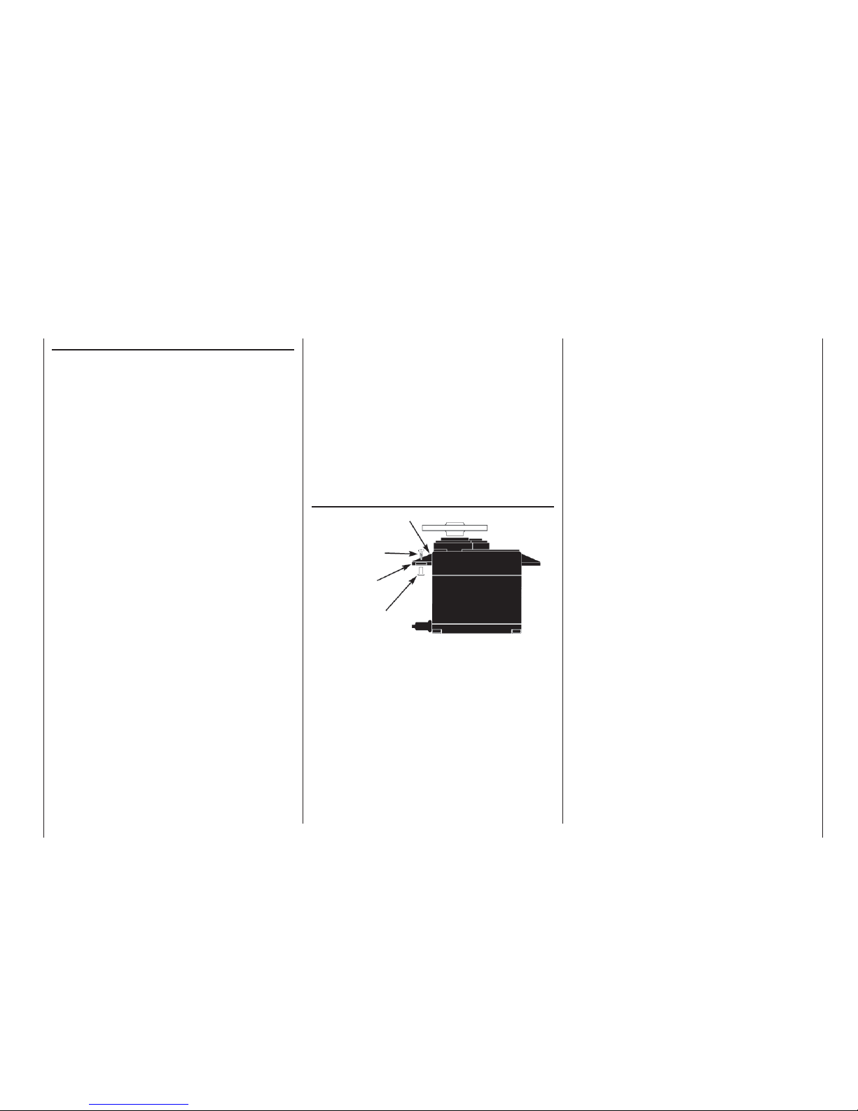
27
Installation notes
Installation notes
Installation notes
Your receiving system must be installed correctly in
the model. The following are a few suggestions when
using GRAUPNER equipment:
1. Wrap the receiver in (anti-static) foam rubber at
least 6 mm thick. Fix the foam round the receiver using rubber bands to protect it from vibration,
hard landings and crash damage.
2. The receiver aerial must be secured in the model,
so that there is no chance of it becoming tangled
in the propeller or control surfaces. However, never deploy the aerial in an exactly straight line, but
angle it: e. g. run it straight to the tailplane, then
leave the fi nal 10 - 15 cm trailing freely, as this
avoids reception “blind spots” when the model is in
the air. If this is not possible, we recommend that
you lay out part of the aerial wire in an S-shape inside the model, as close to the receiver as possible.
3. All switches must be installed in a position where
they will not be affected by exhaust gases or vibration. The switch toggle must be free to move over
its full range of travel.
4. Always install servos using the vibration-damping
grommets and tubular metal spacers supplied. The
rubber grommets provide some degree of protection from mechanical shocks and severe vibration.
The drawing on the right shows the correct method of mounting a servo. The metal spacers are
fi tted into the rubber grommets from underneath.
Don’t over-tighten the servo retaining screws, as
this will compress the grommets and thereby reduce the vibration protection they afford. The system
offers good security and effective vibration protection for your servos, but only if the servo retaining
screws are fi tted and tightened properly.
5. The servo output arms must be free to move over
their full arc of travel; ensure that no part of the
Servo mounting lug
Retaining screw
Rubber grommet
Brass tubular spacer
mechanical linkage can obstruct the servo in its
movement. It is also mandatory to ensure that the
servo is not stalled mechanically at any point in its
travel. If this is the case, re-connect the mechanical linkage to reduce the linear travel, or reduce
the servo travel at the transmitter. This is carried
out in the option “Travel reduction” in the »Servo
adjustment« menu.
The sequence in which the servos are connected to
the receiver is dictated by the model type. Please see
the socket assignments listed on pages 37 and 43.
Be sure to read the safety notes on pages 4 … 6.
Servo mounting
If the receiver is ever switched on when the transmitter is off, the servos may carry out uncontrolled movements. You can avoid this by keeping to the following
order when switching the system on:
Always switch the transmitter on fi rst,
followed by the receiver.
And when switching the system off:
Always switch the receiver off fi rst,
followed by the transmitter.
When programming the transmitter you must always
ensure that any electric motors in the system cannot
possibly burst into life accidentally, and that an I. C.
engine fi tted with an automatic starter cannot start
unintentionally. In the interests of safety it is always
best to disconnect the fl ight battery, or cut off the fuel
supply, before carrying out any programming work.
Range checking
Before every session you should always check that
each working system is functioning correctly, and carry out a range check with the model on the ground.
The transmitter aerial should be fi tted but collapsed
completely. Carry the aerial a suitable distance from
the model, operating the controls all the time: each
function should work smoothly and correctly during
this test. If your model is powered, repeat the check
with the motor running to ensure that it does not cause interference.
Page 28
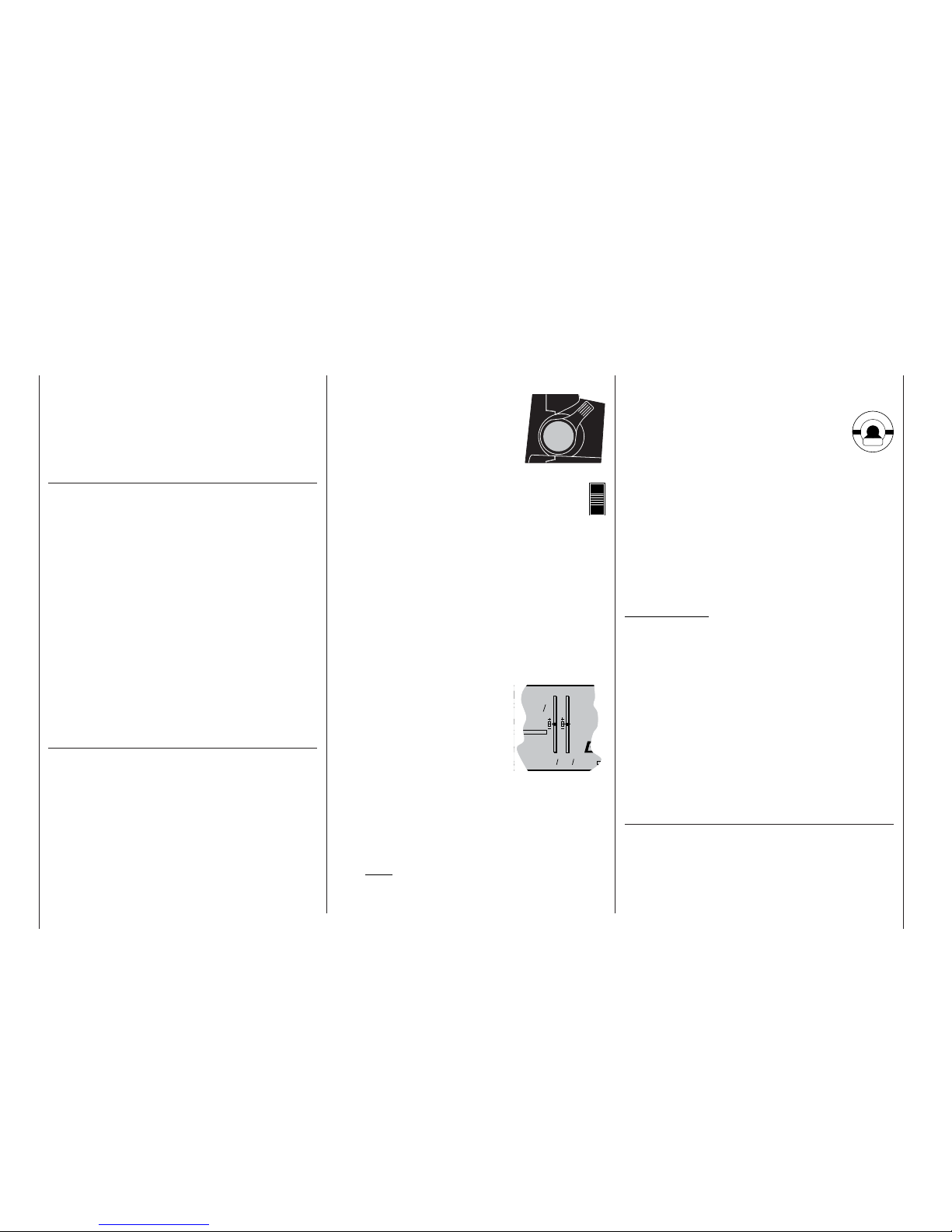
28
Defi nition of terms
Control functions, transmitter controls, function inputs, control channels, mixers, switches,
control switches, fi xed switches
Defi nition of terms
To make it easier for you to understand the mx-24s
manual, we present at this stage two pages of defi nitions of terms which crop up again and again in the
remainder of the text, together with a basic fl ow chart
of the course of the signal from the transmitter control to the point where it is broadcast from the transmitter aerial.
Control function
The term “control function” can be thought of as the
signal which is generated in order to control a particular function – initially independent of the course
of the signal in the transmitter. In the case of fi xedwing model aircraft, throttle, rudder and aileron represent control functions, whereas collective pitch, rollaxis and pitch-axis are typical of those used to control model helicopters. The signal of a control function may be assigned directly to a control channel, or
to several control channels via mixers. A typical example of the latter is a pair of separate aileron servos, or two roll-axis or pitch-axis servos in a model
helicopter. In particular, the control function includes
the infl uence of the travel of the mechanical transmitter control on the corresponding servo. This can be
expanded or compressed by means of software; it is
also possible to modify the characteristics of the travel from linear at one end of the scale to extreme exponential at the other.
Transmitter control (CTRL)
The term “transmitter control” refers to the mechanical elements on the transmitter which are operated
directly by the pilot. Their movements in turn produce
corresponding movements in the servos, speed controllers etc. at the receiver end. Transmitter controls
include the following:
• The two dual-axis stick units for the control func-
tions 1 to 4; these four functions can be interchanged in any way you like through software, e. g.
throttle left or right, without having to re-connect
the servos. The dual-axis stick function for throttle or airbrake control is often known as the C1
(Channel 1) control.
• The two proportional controls
located on the sides of the case,
which are always referred to as
controls number 9 (right-hand
“rotary slider”) and 10 (left-hand
“rotary slider”) at various points
in the program.
• The two transmitter controls termed CONTROL 5 and 6. On the
mx-24s these have a
dual function:
a) If these two transmitter controls are not assi-
gned to any of the inputs in the »Control ad-
just« menu (see pages 78 and 80), they can
be used as INCrement / DECrement buttons for
adjusting values in the “+” (INC) and “-” (DEC)
directions, as an alternative to the ROTARY
control.
b) If they are assigned as transmitter controls in
the »Control adjust« menu, they change the
position of the associated servo by a 1% increment (relative to the currently set servo travel –
see the »Servo adjustment« menu) every time
they are pressed. The positions are superimposed on
the basic screen display immediately the buttons are
pressed, or when you press
the rotary control. This is
ideal, for example, for setting the camber-changing
fl aps to different positions in individual fl ight
phases. If they are held pressed in for a longer
time, the rate of change alters automatically –
made audible by a faster sequence of beeps.
You will also hear an audible signal when the
buttons reach the centre position.
Note:
The position of these two transmitter controls
is always stored separately for each fl ight phase, provided that they have been assigned to
one of the inputs 5 … 12 in the »Control ad-
just« menu.
• However, the servos can also be switched between three different fi xed positions (forward - centre - back) by means
of the three-position switches termed
CONTROL 7 and 8. They can also be switched
between two positions (forward - back) using any
of the remaining switches (SW = abbreviation for
switch), e. g. from the one servo end-point to the
other. The individual positions which a servo takes
up at each switch position can be set individually
(see the »Control adjust« menu, pages 78 and
80, and the »Servo adjustment« menu, page 74).
The transmitter control or switch which operates each
one of the servos 5 … max. 12 is freely programmable, without restriction.
Important note:
In the default state of the transmitter software all
these inputs are set to “free”, i. e. they are not assigned to any functions as standard.
The numbers printed on the transmitter are intended
exclusively to help you keep track of the programming procedure. Only in the Helicopter menu is the
right-hand side-mounted proportional control (CONTROL 9) already assigned to the “Throttle limit function”; see page 82. In the Helicopter menu, inputs 6,
7 and 12 are also assigned to “Throttle”, “Gyro” and
“Throttle limit” respectively, since helicopter-specifi c
functions are controlled using these inputs.
Physically and terminologically each transmitter control terminates where it reaches the …
Function input
This is an imaginary point in the signal path, and
must not be considered the same as the point on the
circuit board where the transmitter control is connected. In fact, the line “Stick mode” of the menu »Model
type« and the menu »Control adjust« infl uence the
sequence “down-stream” of these connections, i. e. it
CM20
er
C65
0 0
Stop
Flight
ame
Page 29
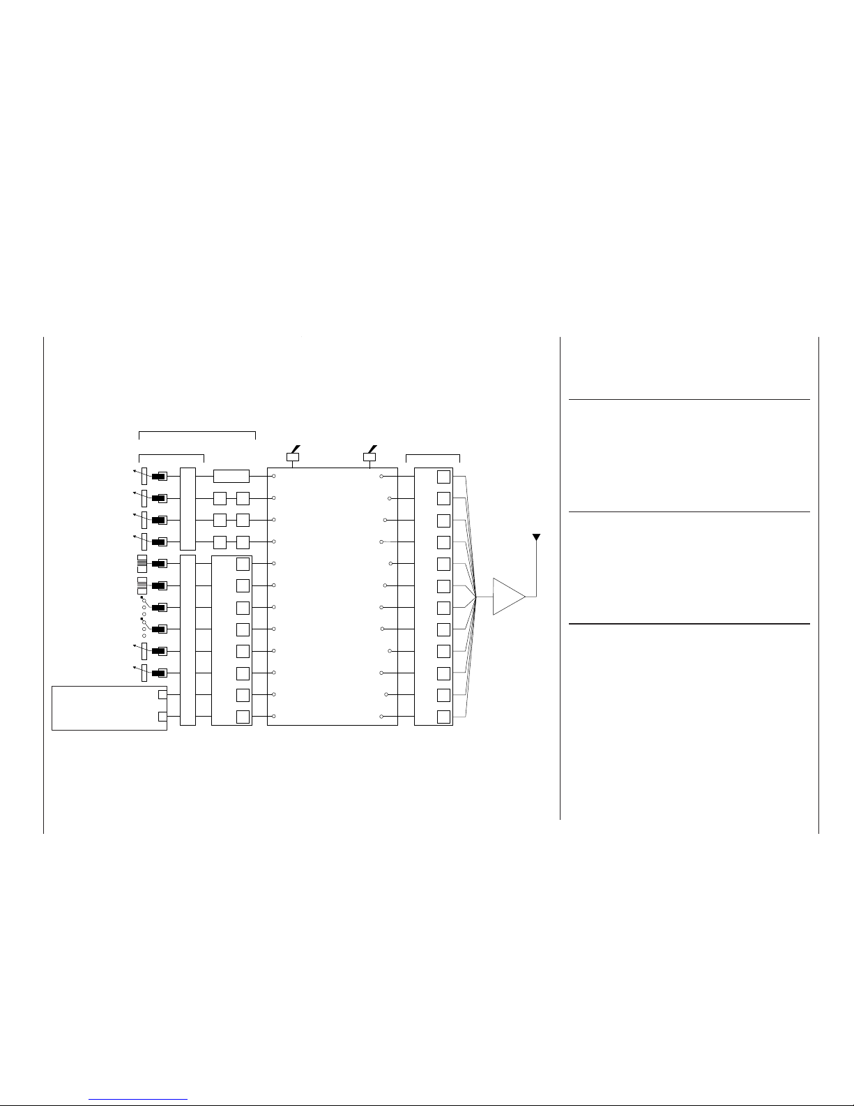
29
D/R EXPO
D/R EXPO
D/R EXPO
5
6
7
8
9
10
11
12
RF
5
6
7
8
9
10
11
12
1
2
3
4
is possible – and indeed likely – that there will be differences between the number of the transmitter control and the number of the subsequent control channel.
Control channel
There is a point in the signal path where the signal
contains all the information required to control a particular servo. Whether it emanates directly from a
transmitter control or indirectly via a mixer, we now
describe this as a control channel. This signal is generated individually for each servo, and then leaves
the transmitter via the RF module in order to control
the corresponding servo in the model.
Mixers
The signal fl ow chart includes a wide range of mixer
functions. Their purpose is to enable a control function to branch at the mixer input, so that it can affect
multiple servos. The mixer programs provided by the
software are extremely wide-ranging and versatile.
Please refer to the section of this manual starting on
page 110, which describes the numerous mixer functions in full detail.
Switches (SW)
Earlier we saw that the two-position and three-position switches provided by the
mx-24s are able to
move their associated servos to two or three pre-defi ned positions. However, all these switches are also
designed to be used for switching program options,
e. g. for starting and stopping timers, switching mixers on and off, toggling Trainer mode etc.. For this
reason the two three-position switches are also described as “SW 5 + 6” and “SW 9 + 10”. The switch
SW 8 – top right, rear – is a self-neutralising unit.
Each switch can be assigned as many functions as
you wish. The linking of several switches in “AND”
or “OR” combinations (see the »Logical switches«
menu on page 97) enables them to be used in very
complex superimposed arrangements. Numerous examples are described later in this manual.
Defi nition of terms
Control function
Control channel
Aerial
Servo adjustment: reverse - centre - travel - limit
mx-24s-Programme
For example:
Model type
Helicopter type
Control switches
Logical switches
Phase settings
Phase assignment
Non-delayed channels
Wing mixers
Helicopter mixers
Free mixers
MIX active in phase
MIX only channel
Dual mixers
2-position switch
3-position switch
For switching mixers, auto-
rotation, fl ight phases etc.
Function input
Channel 1
curve
Dual-axis stick unit
Dual-axis stick unit
Transmitter control
(digital button) 5
Transmitter control
(digital button) 6
Transmitter control 7
(3-position switch)
Transmitter control 8
(3-position switch)
Transmitter control 9
(right-hand side-mounted
rotary control)
Free assignment of
transmitter controls 1,
5 … 10 and of all switches (SW) by software
Stick mode 1 … 4Unrestricted transmitter control assignment, inputs 5 … 12
Transmitter control settings: offset - control travel - time
Transmitter controls
By default transmitter controls
5 …12 are de-coupled in the
software – (exception:
Throttle limiter control)
Transmitter control inputs 1 …
4 can be interchanged in the
»Base setup model« menu.
Transmitter controls 1 and 5
… 10 can be assigned to in-
puts 5 … 12 in any order in
the »Control adjust« menu.
Mixer input
Mixer output
Transmitter control 10
(left-hand side-mounted
rotary control)
Signal fl ow chart
or
Page 30
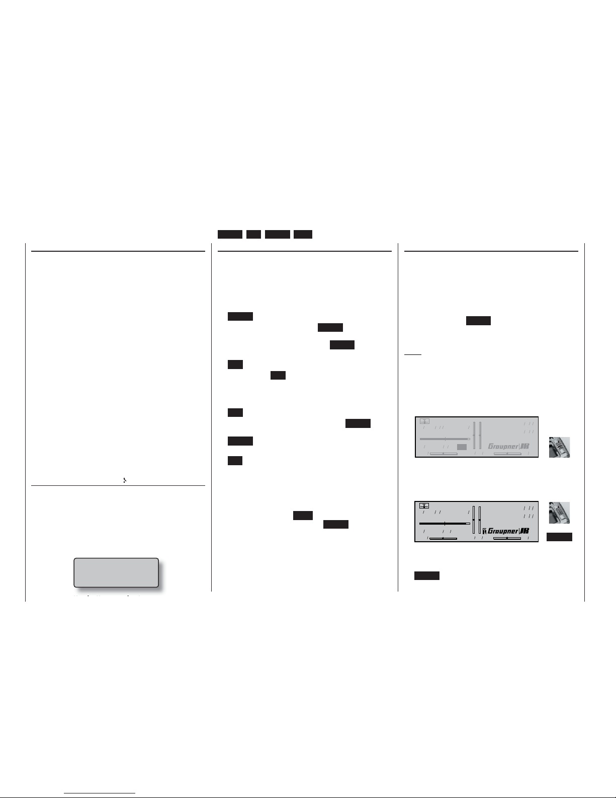
30
Transmitter buttons and rotary control
Transmitter control switches
Sometimes it is desirable to switch a function on or
off at a particular position of another transmitter control, e. g. at a defi ned position of one of the dual-axis
sticks. Typical examples are switching a stopwatch
on and off, extending spoilers automatically, and
many others.
The
mx-24s software includes a total of eight soft-
ware “switches” of this type, termed “G1 … G8”. All
you have to do is defi ne the switching point on the
travel of the transmitter control; this just requires
pushing a button. The direction of switching can be
determined in the software by operating the associated transmitter control at the stage when the control
switch is assigned.
In the »Control switches« menu, pages 78 and 80,
you will fi nd that two frequently needed control switches are already pre-programmed: both of them on
the throttle stick (“Control 1”) with a switching point at
-75% (G1) and +75% travel (G2).
Naturally, transmitter control switches can also be
combined in order to solve more complex problems;
they can also be used in conjunction with the physical switches which have already been described.
A series of instructive examples makes it child’s play
to program these functions: please refer to the programming examples starting on pages 94, 170, ...
Fixed switches FXI and FX
This type of switch turns a function on permanently
– e. g. a timer (closed fi xed switch) or off permanently (open fi xed switch). These two fi xed switches are
part of a range of “expanded switches”, to which the
logical switches also belong. They can be programmed in any of the menus in which the following window is superimposed when an assignment is made
(see page 32 for more details):
Move desired switch
to ON position
(ext. switch: ENTER)
Operating buttons
The transmitter is programmed using just four buttons situated to the left of the screen, in conjunction
with the crucial element: the “3-D rotary control” to the
right of the screen, the functions of which are described on the following page.
Operating buttons:
• ENTER
The fi rst time you press the ENTER button you
move from the basic screen display to the multifunction menus. You also press ENTER to call up
a selected menu.
• ESC = ESCAPE
Pressing the ESC button takes you one step back
at the function select stage, and continues to return you through the system until you reach the
basic display.
• CLR = CLEAR
At the programming stage, pressing CLEAR re-
sets an altered parameter to the default value.
CLEAR is also used to leaf backwards through the
pages within the Help system.
• HLP = HELP
At any point in the programming process you can
press this button to call up a brief Help text which
informs you how to use the individual menu in
which you are currently located. Within the Help
text you can leaf forwards through the screen pages by pressing the HELP button again, and leaf
through backwards using the CLEAR button.
Basic operations
Button pad, hotkeys for fast acccess, functions of the rotary control
ENTER, ESC, CLEAR, HELP, contrast adjustment, button pad lock
Hotkeys, functions of the rotary control
The basic method of using the rotary control has already been described on page 20. Here we show an
example of using the rotary control in a practical application.
First switch the transmitter on (the method of selecting a channel and using the scanner have already
been described in the section starting on page 24).
Now just press the ENTER button, so that the RF module remains switched off. You are now at the basic
screen display.
Note:
If the two digital buttons CONTROL 5 and / or 6 have
not already been assigned to other purposes, e. g. in
the case of a brand-new transmitter or a newly initialised model memory, these buttons have exactly the
same effect as turning the rotary control.
• Adjusting screen contrast
Model name
#01 0:00h SPCM20
H-J.Sandbrunner
10.9V
0:05h C65
0 0 0 0
Stop watch
Flight tim
000
000
:
:
Press and
Press and
rotate
rotate
You can adjust the screen display to suit the ambient conditions by pressing and turning the rotary control.
• Switching the button pad lock on and off
Model name
#01 0:05h SPCM20
H-J.Sandbrunner
10.9V
0:30h C65
0 0 0 0
Stop watch
Flight tim
000
000
:
:
+
CLEAR
A key symbol to the left of the GRAUPNER/JR
logo indicates that the button pad is locked. You
can unlock or lock the button pad by pressing the
CLEAR button whilst holding the rotary control
pressed in.
Page 31

31
• Quick-Select
Hold rota-
Hold rota-
ry control
ry control
pressed in
pressed in
All codes
!
Base servo sett.
Switches
Timers
Special funct.
Memory
Transm. controls
Flight phases
Mixers
Global functions
From the multi-function list you can move to a “pro-
gram structure summary” with a long press on the
rotary control. In the interests of clarity, this summary shows the menus grouped together logically.
Continue to hold the rotary control pressed in, and
select the desired block of menus. As soon as you
release the rotary control again, the on-screen list
will include only those menus associated with the
category type.
• Slot time
The slot time can be stopped by pressing the ESC
button with the rotary control pressed in, and then
reset by pressing the CLR button.
• Menu settings
A brief press on the rotary control or ENTER takes
you to a menu, while pressing ESC takes you
back again.
Now select a line within a menu:
BASIC SETTINGS, MODEL
Stick mode
Info
Model name
Modulation
Press and
Press and
rotate
rotate
Call up an input fi eld:
Brief
Brief
press
press
BASIC SETTINGS, MODEL
Stick mode
Info
Model name
Modulation
SEL
1
Fast access hotkeys, additional functions of the rotary control
Hotkeys for: servo display, model select, multi-function list, quick-select and slot time; using the rotary control for menu settings
• Servo Display hotkey
1 - 1 0 0 % 2 0 %
3 + 1 0 0 % 4 0 %
5 0 % 6 - 1 2 5 %
7 0 % 8 0 %
9 0 % 1 0 0 %
1 1 0 % 1 2 0 %
+
HELP
During the programming process you can move
directly to the »Servo display« menu (see page
156) from the basic display and from virtually any
menu by pressing the HELP button with the rotary
control pressed in.
This display shows the servo travels, taking into
account all mixer and set-up values.
Pressing the rotary control again immediately re-
turns you to your starting point.
• Model Select hotkey
+
ENTER
Graubele
02 Soarmaster
2:45h
03 DV20KATANA 5:46h still in test
04
Starlet 50
8:31h
05
free
01
06
1:25h
PCM20 1675Gr
PPM18 070707
trim: new adj.
free
From the basic display you can move directly to
the »Model select« menu (see page 59) by pressing the ENTER button with the rotary control
pressed in.
• Calling up the multi-function list from the basic
display
Base setup model
Model select
Suppress codes
Servo adjustment
Control adjust
Channel 1 curve
Copy / Erase
Suppress models
Model type
Stick mode
Dual Rate / Expo
Switch display
Select
Select
menu
menu
A brief press on the rotary control or ENTER takes
you to the multi-function list, while ESC takes you
back again.
Select the menu you wish to use by turning the ro-
tary control (or using CONTROL 5 or 6).
Transmitter buttons and rotary control
Change a value:
BASIC SETTINGS, MODEL
Stick mode
Info
Model name
Modulation
SEL
2
Rotate
Rotate
Confi rm input and quit:
BASIC SETTINGS, MODEL
Stick mode
Info
Model name
Modulation
2
SEL
Brief
Brief
press
press
If you can see function fi elds in the bottom line in
addition to the SEL fi eld, you can access them by
turning the rotary control.
Press ESC to return step by step to the previous
page.
Page 32

32
Assigning transmitter controls and switches
The
mx-24s offers maximum fl exibility in terms of as-
signing the standard transmitter controls to particular
functions.
Since the method of assigning transmitter controls
and switches is the same in all the relevant menus,
we shall explain the basic programming at this point,
so that you can concentrate on the specialised content when reading the detailed descriptions of the individual menus.
In the »Control adjust« menu …
… (see pages 78 / 80) you can assign Control 1, and
any other transmitter controls designated “CTRL”, or
switches designated “SW”, to the transmitter inputs 5
… 12 in order to control servos. The screen displays
the following window:
Now just operate one of the following transmitter controls (CTRL) or switches (SW):
Notes:
The software only detects the two INC / DEC buttons
5 + 6 after a few “beeps”. This means that you must
hold them pressed in the up or down direction until
the assignment is displayed on-screen. If there is insuffi cient travel for this, simply move the control in the
opposite direction.
Assigning transmitter controls, switches and control switches
Basic procedure, meaning of the fi xed switches “FX”
In the »Control switch« menu …
… (see page 94) this message is superimposed:
Important note:
If you wish to assign the transmitter controls (especially CONTROL 5 + 6), it is ESSENTIAL to assign them to one of the inputs 5 to 12 beforehand;
this is carried out in the »Control adjust« menu.
In addition to the transmitter controls mentioned above (see left column), you can also select one of the
four dual-axis stick functions simply by moving the
stick physically forward or back, or to right or left.
Assigning switches
The switch symbol
appears in the bottom line of
the screen at all points in the programming procedure
where switches can be assigned.
If you move to this fi eld using the rotary control, the
switch symbol fi eld changes to highlighted (black
background):
This is how you assign one of the switches:
1. Brief press on the rotary control
2. The following fi eld appears on the screen:
Now simply select the switch you wish to use and
move it to the “ON” position, following the instructions in the window; this completes the assignment
process, and the switch appears on the screen for
the relevant menu. A switch symbol adjacent to
the switch number shows the current status of the
associated switch.
The three-position switches designated CTRL 7
and 8 and also SW 5 / 6 and 9 / 10 can be used
purely as switches as well as for the purpose of
transmitter controls, which means that a total of
ten switches (“SW 1 … 10”) is available to you for
any purpose.
Note:
The position to which you eventually move the
switch (in order to assign it) is accepted by the
transmitter as the ON position. For this reason you
should move the external switch to your intended
OFF position before you activate the switch symbol.
3. Changing the direction of switching
If the switch turns out to work in the wrong direc-
tion, you can correct it as follows: move the switch
to the desired OFF position, select the switch symbol once more, and assign the switch again, this
time with the direction of switching you prefer.
4. Erasing switches
First activate the switch symbol as described un-
der Point 2, then press the CLEAR button.
Assigning from the “Expanded switches” list
In various menus it is possible to assign the switches
designated “SW”. These menus are defi ned by the
appearance of the following superimposed window …
In these menus it is also possible to assign any of the
so-called “expanded switches”.
This is accomplished by following the instructions in
Switch assignment
Move desired switch
or control adj.
Move desired switch
to ON position
(ext. switch: ENTER)
Move desired
control adj.
CTRL
5 + 6
CTRL 7 + 8
or SW 1 ... 10
CTRL
9 + 10
Throttle stick
C1
Move desired switch
to ON position
(ext. switch: ENTER)
Page 33

33
Switch assignment / Function fi elds
Using the transmitter control switches “G1 … G8”
For some special functions it may be preferable to
trigger the switching action at a particular position of
a transmitter control, rather than manually using a
normal switch (SW). Of course, you can vary the position of the control when the switch is triggered.
Eight switches of this type, termed control switches
G1 ... G8, are available for this purpose; their switching direction can be reversed (inverted) in the
»Control switches« menu; see page 94.
How to assign a control switch
Starting from the selected (and therefore highlighted)
switch symbol (
) in the appropriate menu, just
operate the desired transmitter control when the window …
… is superimposed on the screen.
The direction of movement when you assign the con-
trol also determines the switching direction “Switch
open / closed”. A switch symbol after the assignment
indicates the switch status: “ ” or “ ”.
However, if the switching direction is not correct, the
solution is to press the CLEAR button to erase the
control switch when the window shown above is superimposed, and then re-assign the control switch
with the new switching direction, as described above.
Note:
All the switches described thus far can also be
assigned to multiple functions. Please take care
to avoid ACCIDENTALLY assigning several functions to one switch where they could interfere with each other. We recommend that you write
down the switch functions you have assigned.
Move desired switch
to ON position
(ext. switch: ENTER)
the window, i. e. by pressing the ENTER button: a
new window now appears showing a list containing
the two fi xed switches “FX” and the logical switches
“L1 … L8” and “L8i … L8i”:
Turn the rotary control to select the desired switch; if
you reach the end of the second line you will see the
switches L3i to L8i superimposed:
Fixed switches
The two FX switches turn a function either on (“FXI”)
or off (“FX
”) permanently.
Logical switches
Using the logical switches – see »Logical switches«
menu, page 97 – you can link together two switches
and / or control switches logically in an “AND” or “OR”
manner. The software provides a total of eight logical
switches “L1 … L8” (plus a further eight inverted logical switches, with the opposite switching direction).
However, the outcome of one of these logical switched functions can equally well be used as a switched function in a further logical switch arrangement.
See the appropriate menu for more details of this.
Gewünschten Schalter
oder Geber betätigen
(erw. Schalt.: ENTER)
Logical / fixed switch
FX L1 L2
FXI
L3 L4
L5 L6 L7 L8 L1i L2i
In certain menus you will see function fi elds in the
bottom line of the screen; they can be called up using
the rotary control:
TOG ASY
SYM
SEL
STO CLR ENT
• TOG: Include / suppress menus
• SEL (select): Select
• : Switch symbol fi eld (assigning switches, control switches and logical
switches)
• STO (store): Store (save) (e. g. transmitter control
position)
• CLR (clear): Erase (e. g. curve reference point)
• SYM: Adjust values symmetrically
• ASY: Adjust values asymmetrically
• ENT (enter): Only in the »Code lock« menu
• : Switch to second page (next menu)
within a menu
Function fi elds
SEL, STO, CLR, SYM, ASY, , TOG, , ENT
Gewünschten Schalter
oder Geber betätigen
(erw. Schalt.: ENTER)
FXI
L5 L6 L7 L8 L1i L2i
L3i L4i L5i L6i L7i L8i
Logical / fixed switch
Page 34

34
Digital trims
Description of function, and C1 cut-off trim
Digital trims with visual and audible indicators
Both the dual-axis stick units are fi tted with digital trim
systems. When you give the trim lever a brief push
(one “click”), the neutral position of the associated
stick channel changes by one increment. If you hold
the trim lever in one direction, the trim value changes
continuously in the corresponding direction with increasing speed. The trim increment can be set to any value in the range “1” to “10” in the »Stick mode« menu
(see pages 76 / 77), corresponding to servo travel of
around 0.2% … 3% per click. The current position and
numerical trim value are displayed on the screen.
The degree of trim offset is also “audible”, as the pitch
of the tone changes to refl ect the setting. When you
are fl ying a model, you can fi nd the trim centre position easily without having to look at the screen: if you
over-run the centre setting, the trim stays in the centre position for a moment before continuing.
The current trim values are automatically stored when
you switch from one model memory to another.
The digital trims can also be stored globally or separately for each fl ight phase within a model memory, with the exception of the “C1” (Channel 1) trim,
which is the throttle / airbrake trim on a fi xed-wing
model. The “global” or “phase” setting is selected in
the »Stick mode« menu (see pages 76 / 77). Note
that the C1 trim is always set to “global” in the software, i. e. it acts independently of any fl ight phases you
may have set.
In the basic display this pre-set is indicated by a form
of “shadow” at the trim display bars:
• Shadow present = global,
• Shadow suppressed = fl ight phase specifi c.
In the model memory to which the following screen-
shot relates two trims have been set separately for
each fl ight phase (“phase” setting):
Model name
#01 0:05h SPCM20
H-J.Sandbrunner
10.9V
0:10h C65
0 0 0 0
Stop watch
Flight tim
000
000
:
:
1. Fixed-wing model aircraft
The C1 trim features a special function which
makes it easy to re-locate the correct idle setting
of an internal-combustion engine – provided that
you have selected “Throttle min. forward or back”
in the “Motor” line of the »Model type« menu (see
page 70). If not, the cut-off trim is permanently
disabled.
Initially you use the trim lever in the usual way to
select a reliable idle setting for the motor. If you
move the C1 trim lever to its end-point in the direction of “motor cut-off”, pushing the lever in a single
movement, a marker appears on the screen at the
last position. You can now return to the correct idle
setting for starting the motor simply by pushing the
trim one click in the direction of “open throttle”.
Notes:
• Since this trim function only takes effect in the
“Motor stopped” direction, the screen image
shown above changes if you alter the throttle minimum position of the C1 stick from “back”
(as shown in the screen-shot above) to “forward” in the “Motor” line of the »Model type«
menu.
• Naturally you can assign the C1 stick to the
left-hand dual-axis stick unit if you prefer; see
the »Base setup model« menu, described on
page 64.
2. Model helicopters
In Helicopter mode the C1 trim has another fea-
ture in addition to “cut-off trim”, as described under
“Fixed-wing model aircraft” above; this time in conjunction with the “Throttle limit function”: using a
“throttle limit slider” the throttle servo travel can be
limited in the direction of full throttle. For more details of this please turn to page 82.
Note regarding helicopters:
The C1 trim only affects the throttle servo and not
the collective pitch servos; it also works only in the
direction of idle. Please note that the helicopter
throttle servo must be connected to receiver output 6 (see Receiver socket assignment on page
43).
Digital trims
:30h SPCM20
ndbrunner
0:30h V65
28100 0
Stop
Flight
000
000
:
:
m Modèle
Current
trim position
Trim value
Trim
direction indicator
C1 trim lever
Last C1 trim position
Idle direction
M20
r
65
28100 0
Stop w
Flight
000
000
:
:
le
Marker indicates the last C1
trim position (idle setting)
Throttle limit slider
Trim position at which the motor is cut
Page 35

35
For your notes
Page 36

36
Fixed-wing models
Fixed-wing models
This program provides straightforward, carefully tailored support for conventional models with up to two aileron servos and four fl ap servos, V-tail models, fl ying
wings and deltas with two elevon (aileron / elevator) servos and up to four fl ap servos. However, the
vast majority of power model and gliders belong to
the “normal” tail type with one servo each for elevator, rudder, ailerons and throttle (or electronic speed
controller, or airbrakes on a glider). There is also the
special model type “2 EL Sv 3+8” which automatically
provides a means of connecting two elevator servos
to channels 3 and 8.
If the model has a V-tail instead of a standard tail confi guration, you should select the “V-tail” type in the
»Model type« menu, as this mixes together the elevator and rudder functions in the required way, i. e.
each tail control surface is actuated by a separate
servo, and both assume superimposed elevator and
rudder functions.
If your model features two separate aileron servos,
the aileron travels can be set up with differential movement, i. e. the down-travel can be set independently of the up-travel. Finally the program caters for camber-changing fl aps which can be operated, for example, by the transmitter control assigned to input “6”
in the »Transmitter control adjust« menu.
The “fl ap differential” function can be used to provide
differential travel when the fl aps are programmed to
follow the aileron function.
For deltas and fl ying wings it is easy to set up mixed
elevons, i. e. the aileron and elevator functions can be
carried out by common control surfaces at the trailing
edge of the right and left wing. The program contains
the appropriate mixer functions for the two servos as
standard.
Up to eight fl ight phases can be programmed in each
of the forty model memories provided by the
mx-
24s (see the »Phase settings« and »Phase assign-
ment« menus). A copy facility is provided, making the
setting of individual fl ight phases much easier (see
the »Copy / Erase« menu).
Four timers are available at all times when fl ying. Additional timers and a lap counter with stopwatch function can also be displayed on-screen, separately for
each fl ight phase (»Timers (general)« and »Flight
phase timers« menus). The screen also displays the
transmitter operating time and the time which has
elapsed for each model memory.
Phase-specifi c trims can be stored for fl aps, ailerons
and elevator (see the »Phase trim F3B« menu).
The digital trim positions can be stored either globally
or separately for each fl ight phase – with the exception of the C1 trim. The digital motor-cut trim provides
a simple means of re-locating the correct idle throttle setting.
“Dual Rate” and “Exponential” can be programmed for
aileron, rudder and elevator, giving two modes of control in each fl ight phase.
As an option, a transmitter control (C1 stick, sidemounted proportional control, INC / DEC buttons or
switch) can be assigned to inputs 5 … 8, separately
for each fl ight phase (see »Control adjust« menu).
In addition to eight freely assignable linear mixers, the
program offers four curve mixers (see »Free mixers«
menu), four dual mixers (see »Dual mixers« menu)
and fl ight phase specifi c eight-point curves (see
»Channel 1 curve«) for channel 1 (throttle / brake).
The »Wing mixers« menu presents you with a list of
pre-defi ned mixers and coupling functions from which
you can choose; the list varies according to the number of wing-mounted servos you have entered.
1. Multi-fl ap menu: control of camber-changing fl aps
as ailerons. Infl uence of aileron trim on fl aps when
operated as ailerons, fl ap differential, travel of the
fl ap function of all pairs of ailerons and fl aps, ailerons operating as camber-changing fl aps. Elevator
3 6 fl ap mixer.
2. Airbrake settings: Butterfl y (Crow), differential reduction, elevator curve
3. Aileron 2 4 rudder mixer
4. Flap 6 3 elevator mixer
left
right
Brake
Flap
Brake
Elevator
Airbrake-Funktion 1
left
right
Rudder/Elevator
V-tail
Brake
FL, FL2
Brake
Elevator
Brake
Aileron
Ail
FL1
FL2
Ail
FL1
FL2
Ail
Flap
Flap
Ail
E
l
e
v
.
A
i
l
e
r
.
E
l
e
v
.
F
l
a
p
F
l
a
p
E
l
e
v
.
A
i
l
e
r
.
R
u
d
d
e
r
F
l
a
p
A
i
l
e
r
.
A
i
l
e
r
.
F
l
a
p
A
i
l
e
r
.
R
u
d
d
.
F
l
a
p
E
l
e
v
.
E
l
e
v
.
F
l
a
p
A
i
l
e
r
.
F
l
a
p
E
l
e
v
a
t
o
r
A
i
l
e
r
o
n
A
i
l
e
r
o
n
R
u
d
d
e
r
F
l
a
p
,
F
l
a
p
2
E
l
e
v
a
t
o
r
E
l
e
v
.
F
l
a
p
,
F
l
a
p
2
A
i
l
e
r
o
n
F
l
a
p
,
F
l
a
p
2
F
L
1
F
L
2
A
i
l
A
i
l
F
L
1
,
F
L
2
F
L
1
,
F
L
2
A
i
l
Option: two pairs of flaps FL1, FL2
Page 37

37
Fixed-wing models
In the following section you will fi nd the receiver socket sequence which is required for your model, starting with “standard models” with no more than two
control surfaces per wing panel. For a six-fl ap model
please turn to page 38. For an eight-fl ap model you
need a receiver with at least ten servo outputs (twelve
is even better); the receiver socket sequence for this
is described on page 184.
Receiver socket sequence for models with up to
four control surfaces per wing panel
The servos MUST be connected to the receiver outputs in the following order:
Models with the “normal” and “V-tail” tail type
Models with the “Delta / Flying wing” tail type
If the model features a second rudder servo, it should
be connected to output 5. A dual mixer (»Dual mi-
xers« menu – see page 144) of the “ 5 RU”
type has to be programmed so that the rudder stick
operates the second rudder in parallel with the fi rst
rudder; differential travel of the two rudders is also
possible with this arrangement.
DUAL MIXER
Mixer RU
0%
Mixer
Diff.
SEL
5
??
??
0%
SEL
Mixer
??
??
0%
SEL
1
2
3
Tips:
The dual mixer shown above permits the pair of rudders or spoilers to be employed as airbrakes using a
transmitter control assigned to input 5 in the »Trans-
mitter control adjust« menu, e. g. one of the sidemounted proportional controls. If you would like to
move the neutral point to one of the two end-points of
the transmitter control, you must set the transmitter
control offset to -100% or +100%; see also page 78.
Models with the “2 EL Sv 3+8” tail type
Second elevator servo
Free, or aux. function, or right fl ap servo
Free, or aux. function or fl ap servo / left fl ap servo
Right aileron servo
Rudder servo
Elevator servo
Aileron servo or left aileron servo
Airbrake or throttle or speed controller
(electric model)
Batt
9
8
7
6
5
4
3
2
1
Free, or aux. function
Battery
Receiver
Note:
Outputs not required should simply be left unused.
Please note the following points in particular:
• If your model features only one aileron servo, receiver output 5 (right aileron) should either be left
unused or employed for an auxiliary function.
• If your model features only one fl ap servo, receiver output 7 (for the right fl ap) and outputs 9 and
10 for the inboard pair of fl aps should either be left
unused or employed for auxiliary functions.
PPM receivers of other makes
If you are using a PPM-FM receiver made by another manufacturer* in a model which was previously
fl own using a non-Graupner transmitter, and you wish
to operate it with a GRAUPNER transmitter, e. g. the
mx-24s for Trainer mode operations, it may be ne-
cessary to re-connect servos to the receiver outputs
in the order stated on the previous page. Alternatively
you can carry out the appropriate adjustments in the
»Receiver output swap« menu, see page 153. You
may also need to adjust servo travels and directions
of rotation; this is always carried out in the »Servo
adjustment« menu; see page 74.
Free, or aux. function
Free, or aux. function, or right fl ap servo
Free, or aux. function or fl ap servo / left fl ap servo
Right aileron servo
Right V-tail servo
Left V-tail servo
Aileron servo or left aileron servo
Airbrake or throttle or speed controller
(electric model)
Batt
9
8
7
6
5
4
3
2
1
Free, or aux. function
Battery
Receiver
Free, or aux. function
Free, or aux. function, or right fl ap servo
Free, or aux. function or fl ap servo / left fl ap ser vo
Free, or aux. function (right rudder)
Rudder
Right elevon servo
Left elevon servo
Airbrake or throttle or speed controller
(electric model)
Batt
9
8
7
6
5
4
3
2
1
Free, or aux. function
Battery
Receiver
Battery
Free, or aux. function
Free, or aux. function, or right fl ap servo
Free, or aux. function or fl ap servo / left fl ap servo
Right aileron servo
Rudder servo
Elevator servo
Aileron servo or left aileron servo
Airbrake or throttle or speed controller
(electric model)
Batt
9
8
7
6
5
4
3
2
1
Free, or aux. function
Receiver
* GRAUPNER does not guarantee that GRAUPNER radio cont-
rol systems will work correctly in conjunction with receiving systems and radio control equipment made by other manufacturers.
Page 38

38
Fixed-wing models
38
Fixed-wing models
Receiver socket sequence for models with six
control surfaces per wing panel and PPM24 or
APCM24 receivers
Models with the “normal” and “2 EL Sv 3+8” tail
type
Models with the “V-tail” tail type
The receiver socket sequence is the same as the
“normal” type with the difference that the two V-tail
servos are connected as listed below:
Models with the “Delta / Flying wing” tail type
Deltas / fl ying wings with two rudders
See the set-up notes on the previous page.
8
2
5
6
1
7
3
4
left
right
8
7
3
2
6
1
4
PPM24, APCM24
Receiver socket sequence for models with six
control surfaces per wing panel and PCM20 or
SPCM20 receivers
When using a PCM transmission link, the control data
is compressed before being transmitted, and if you
use a PCM or SPCM receiver the servos connected to sockets 9 and / or 10 may be slightly less than
smooth-running (see also page 137). This effect may
be particularly noticeable with a six-fl ap model if the
servos for the second pair of fl aps are to be controlled
by the aileron stick (as set up in the “Multi-fl ap menu”
of the »Wing mixers« menu). For this reason it is essential to assign the inboard fl ap servos 9 + 10 to receiver outputs 1 + 8 in the »Receiver output swap«
menu if you are using a PCM or SPCM receiver. For
more details see the later section “PCM and SPCM
receiver output”.
Models with the “normal” and “V-tail” tail type
8
2
5
6
1
7
3
4
Battery
Right fl ap 2
Right fl ap
Flap or left fl ap
Right aileron
Rudder or right V-tail
Elevator or left V-tail
Aileron or left aileron
Left fl ap 2
Batt
9
8
7
6
5
4
3
2
1
10
Free, or aux. function or throttle
Free, or aux. function
Receiver
PCM20, SPCM20
Battery
Free, or second elevator, or aux. function
Right fl ap
Flap or left fl ap
Right aileron servo
Rudder servo
Elevator servo
Aileron servo or left aileron servo
Airbrake or throttle or speed controller
(electric model)
Batt
9
8
7
6
5
4
3
2
1
10
11
12
Left fl ap 2
Right fl ap 2
Receiver
Free, or aux. function
Free, or aux. function
Battery
Free, or aux. function
Right fl ap
Left fl ap
Free, or right rudder
Rudder or left rudder
Right elevon
Left elevon
Airbrake or throttle or speed controller
(electric model)
Batt
9
8
7
6
5
4
3
2
1
10
11
12
Left fl ap 2
Right fl ap 2
Receiver
Free, or aux. function
Free, or aux. function
PPM24, APCM24
Flap or left fl ap
Right aileron servo
Right V-tail servo
Left V-tail servo
Aileron servo or left aileron servo
Airbrake or throttle or speed controller
(electric model)
6
5
4
3
2
1
Receiver
Page 39

3939
Fixed-wing models
Models with the “Delta / Flying wing” tail type
Deltas / fl ying wings with two rudders
See set-up notes on the preceding double page,
right-hand side.
left
right
8
7
3
2
6
1
4
Battery
Right fl ap 2
Right fl ap
Left fl ap
Free, or right rudder, or aux. function
Rudder or left rudder
Right elevon
Left elevon
Left fl ap 2
Batt
9
8
7
6
5
4
3
2
1
10
Free, or aux. function or throttle
Free, or aux. function
Receiver
Interchanging receiver outputs with PCM20 and
SPCM20 receivers
The receiver assignment stated below should be
used for both tail types in order to avoid servos 9 and
10 running jerkily. Carry out the following steps in the
»Receiver output swap« menu:
• assign servo 9 to output 1, and,
• assign servo 10 to output 8.
Moreover, if you …
• … assign servo 1 to output 9, then receiver output
9 is available for other purposes, perhaps for airbrakes, or for throttle using the throttle / airbrake
stick, and
• … assign servo 8 to output 10, then a servo connected to output 10, if present, can be operated by
a transmitter control assigned to input 8 (»Trans-
mitter control adjust« menu), typically for controlling an auxiliary function.
Servos connected to these two outputs (9 + 10) do
run smoothly provided that they are not affected by
mixers.
The »Receiver output swap« menu (page 153)
should therefore be programmed as follows:
Receiver Output
Servo
10
8
10
SEL
9 Output 1
Servo
Servo
Servo
Servo
Servo
Servo
Servo
Servo
Servo
2
3
4
5
6
7
1
8
9
7
6
5
4
3
2
Output
Output
Output
Output
Output
Output
Output
Output
Output
PCM20, SPCM20
Tip:
You should also select this “PCM sequence” for a sixfl ap wing if you are using a PPM receiver with only
eight or nine servo sockets.
Important notes:
• If you re-assign the receiver outputs, please note
that any subsequent changes, such as servo travel adjustment, Dual Rates / Expo, mixers etc.,
must still refer to the basic receiver sequence.
• If you swap over the receiver outputs, please note
that the Fail-Safe programming (“hold” or “pos.”) in
SPCM20 and APCM24 mode always relates to the
default receiver socket numbers; in PCM20 mode,
battery fail-safe always affects receiver output 1.
How are the pairs of ailerons and fl aps controlled?
1. Both pairs of fl aps are controlled with the aileron function using the aileron stick
• By default, the aileron stick only controls the
two aileron servos 2 + 5. Values other than
zero for the fl aps FL and (if present) FL2 can
be entered individually in the “Multi-fl ap menu”
of the »Wing mixers« menu.
2. The ailerons are controlled by the fl ap function
using input 6 (e. g. using the INC / DEC buttons
CTRL 5 or 6)
• By default, a transmitter control which is as-
signed to “Input 6” in the »Control adjust«
menu controls the flaps and (if present) FL2
with 100% travel. Values other than zero for
the ailerons, and – if wished – reduced travels
for the flaps, can be entered individually in the
“Multi-flap menu” of the »Wing mixers« menu.
• If you choose “2 AIL 2 FL” in the “Ailerons /
fl aps” line of the »Model type« menu, a transmitter control assigned to “Input 7” is de-coupled in the software in order to avoid control er-
Page 40

4040
Fixed-wing models
Fixed-wing models
Different methods of installing servos and control linkages may make it necessary to reverse the direction
of rotation of some servos when programming.
The following table provides useful information on
this:
Model
type
Servo rota-
ting in wrong
direction
Remedy
V-tail Rudder and ele-
vator reversed
Reverse servos 3 + 4 in
the »Servo adjustment«
menu
Rudder correct,
elevator reversed
Swap over servos 3 + 4 at
receiver
Elevator correct,
rudder reversed
Reverse servos 3 + 4 in
»Servo adjustment«
menu, and swap over
servos at receiver
Delta,
fl ying
wing
Elevator and ailerons reversed
Reverse servos 2 + 3 in
»Servo adjustment«
menu
Elevator correct,
ailerons reversed
Reverse servos 2 + 3 in
»Servo adjustment«
menu, and swap over
servos at receiver
Ailerons correct,
elevator reversed
Swap over servos 2 + 3 at
receiver
In the “Program descriptions” all menus which are relevant to fi xed-wing models are marked with an “aeroplane” symbol:
This means that you can easily skip irrelevant menus
when programming a fi xed-wing model aircraft.
rors. This means that this input can be used for
fl ight phase specifi c auxiliary functions; see the
programming example “8-fl ap wing”, starting on
page 184.
• For reasons of safety, a transmitter control assigned to “Input 10” is also de-coupled in the
software if you choose “2 AIL 4 FL” in the “Ailerons / fl aps” line of the »Model type« menu.
Tips:
• In the “Multi-fl ap menu” of the »Wing mixers«
menu the fl ap positions can be entered for all pairs
of wing fl aps (AILE, FLAP and FL2), separately
for each fl ight phase. However, you can also enter
the same settings at any time in the »Phase trim
F3B« menu … where you can also set up a phase-specifi c elevator trim function.
• If you prefer, the flap function for all pairs of wing
flaps (AILE, FLAP and FL2) can also be operated using the “throttle / airbrake stick”, provided
that this is not already in use for another purpose. To accomplish this all you need to do is assign
“Transmitter control 1” to Input 6 in the »Transmit-
ter control adjust« menu. However, if you prefer
to operate the flaps using a switch, you can equally well assign one of the two-position or three-position switches (SW) fitted to the
mx-24s to “Input
6”.
Page 41

41
41
For your notes
Page 42

42
Model helicopters
Model helicopters
The continued development of model helicopters and
helicopter components, such as gyros, speed governors, rotor blades etc., has led to the current position where helicopters are capable of sophisticated 3D aerobatics. In contrast, the beginner to helicopter
fl ying needs a simple set-up so that he can quickly
get started on the initial stages of hovering practice,
and then gradually work up to more complex models
which exploit all the options provided by the
mx-24s.
The helicopter program of the mx-24s can cope with
all current model helicopters equipped with 1 ... 4 servos for collective pitch control.
Each model memory can include seven fl ight phases
plus auto-rotation (see the »Transmitter control ad-
just«, »Phase settings« and »Phase assignment«
menus).
As with fi xed-wing model aircraft, the standard timers
are included in the basic display, and additional timers
and a lap counter with stopwatch function can be selected separately for each fl ight phase (»Timers (ge-
neral)« and »Flight phase timers«).
Apart from the collective pitch / throttle trim, all the
digital trims can optionally be stored separately for
each fl ight phase (“phase” setting) or “globally”, i. e.
applying to all fl ight phases. The digital C1 trim provides a simple means of returning to a pre-set idle setting.
The transmitter control assignment for inputs 5 ... 8
can also be set separately for each fl ight phase (see
the »Transmitter control adjust« menu).
During the test-fl ying phase the copy fl ight phase
function can be particularly helpful (see the »Copy /
Erase« menu).
“Dual Rate” and “Exponential” are available for roll,
pitch-axis (elevator) and tail rotor, and they can be
coupled together and programmed to provide two settings in each fl ight phase.
It is possible to set up eight freely assignable linear mixers, and four curve mixers can be programmed
and switched on and off separately in each fl ight phase in the »MIX active in phase« menu. Four dual mixers are also available.
Eight-point curves are provided in the »Helicopter
mixers« menu for the collective pitch, throttle and tail
rotor mixers, variable separately for each fl ight phase,
generating non-linear mixer characteristics. Two separate swashplate mixers are also provided for the roll
and pitch-axis functions. Independently of this feature,
the control curve for the Channel 1 stick can also be
defi ned using up to eight points, separately for each
fl ight phase. These advanced features are not needed by the beginner, who will usually start simply by
setting the hover point to coincide with the stick travel centre.
Pre-programmed mixers in the »Helicopter mixers«
menu:
1. Collective pitch curve (with eight-point curve)
2. Channel 1 throttle (with eight-point curve)
3. Channel 1 tail rotor (with eight-point curve)
4. Tail rotor throttle (with eight-point curve)
5. Roll throttle
6. Roll tail rotor
7. Pitch-axis throttle
8. Pitch-axis tail rotor
9. Gyro suppression
10. Swashplate rotation
11. Swashplate limit
The “Throttle limit” function (Input 12 in the »Trans-
mitter control adjust« menu) provides an effective means of starting the motor in any fl ight phase. By
default, transmitter control 9 – the right-hand sidemounted proportional control – is assigned to input
12, and the position of this “throttle limiter” determines the maximum throttle servo position, i. e. the sidemounted proportional control governs the motor over
the idle range. The programmed throttle curves only
take effect when the proportional control is moved towards full-throttle.
Collective
Pitch Curve
Swashplate
Rotation
Roll
Throttle
Pitch-Axis
Throttle
Channel 1 Throttle
Roll Tail Rotor
Pitch-Axis Tail Rotor
Channel 1 Tail Rotor
C
h
a
n
n
e
l
1
T
ail
R
o
t
o
r
T
a
i
l
R
o
t
o
r
T
h
r
o
t
t
l
e
Page 43

43
Model helicopters
Receiver socket sequence:
The servos MUST be connected to the receiver output sockets in the following sequence:
Outputs not required should simply be left unused.
For more details on the different types of swashplate
please refer to the »Helicopter type« menu described on page 72.
If you are using a PPM-FM receiver made by another manufacturer* in a model which was previously
fl own using a non-Graupner transmitter, and you wish
to operate it with a GRAUPNER transmitter, e. g. the
mx-24s for Trainer mode operations, it may be ne-
cessary to re-connect servos to the outputs in the order stated earlier. Alternatively you can carry out the
adjustments in the »Receiver output swap« menu,
see page 153. You may also need to adjust servo travels and directions of rotation; these adjustments are
always carried out in the »Servo adjustment« menu;
see page 74.
Notes:
• Compared with the receiver channel sequence of
earlier GRAUPNER radio control systems, servo
socket 1 (collective pitch servo) and servo socket
6 (throttle servo) have been interchanged.
• If you are using the
mx-24s but do not want to
abandon separate collective pitch trim, you will
need to set up a suitable mixer in the »Free mi-
xers« menu, e. g. an 8 1 mixer, and program
a symmetrical mixer input of around 25%. Now
move to the »Transmitter control adjust« menu
and assign the left-hand side-mounted proportional control CTRL 10 (still free as standard) to mixer input “8”; alternatively you could assign one
of the two INC / DEC buttons CTRL 5 or 6, if these controls are not already in use for other purposes. The advantage of the latter is that their settings are stored separately for each fl ight phase;
see also page 28.
However, in the interests of safety we also recom-
mend that you de-couple the assigned transmitter control from input 8 in the »Mix only channel«
menu, so that the same transmitter control cannot
also operate a servo connected to receiver output
8. See also Example 3 on page 141.
Different methods of installing servos and control linkages may make it necessary to reverse the direction
of rotation of some servos when programming. You
can correct this by using the servo reverse facility located in the »Servo adjustment« menu, see page
74.
In the “Program descriptions” all menus which are re-
levant to model helicopters are marked with a “helicopter” symbol:
This means that you can easily skip irrelevant menus
when programming a model helicopter.
* GRAUPNER does not guarantee that GRAUPNER radio cont-
rol systems will work correctly in conjunction with receiving systems and radio control equipment made by other manufacturers.
Battery
Free, or speed governor
Free, or gyro gain
Motor speed (throttle servo or speed controller)
Free, or pitch-axis (2) servo (4-point linkage)
Tail rotor servo (gyro system)
Pitch-axis (1) servo
Roll (1) servo
Collective pitch or roll (2) or
pitch-axis servo (2) servo
Batt
9
8
7
6
5
4
3
2
1
10
Free, or aux. function
Free, or aux. function
Receiver
Page 44

44
Brief programming instructions
for all fi xed-wing and helicopter programs
Brief programming instructions
Memories
Memories
• • Model select
Selects a free or occupied model memory 1 … 40. An icon for fi xed-wing ( ) or helicopter ( ) makes it easier
to select the model, as does the information entered in the “Info” line of the »Base setup model« menu.
59
• • Copy / Erase Erase a model memory
Copy contents of one model memory to another memory
Copy from / to
mx-24s and PC
Copy individual fl ight phases within one model memory
Back-up all models to a PC
60
• • Suppress Codes Suppress functions from the multi-function select list within a memory; used for settings which are not to be altered, or which are not required.
62
• • Suppress models Suppress model memories from the list shown in the »Model select« menu, e. g. in order to exclude models
which are not in airworthy condition; also makes the list easier to use.
62
Basic settings
Basic settings
• Base setup model Model name: Max. 10 characters (letters, numbers, special symbols). Characters are selected from a ta-
ble using the rotary control.
Info: Max. 15 characters per model memory. Appears next to the model name in the »Model se-
lect« menu. Characters are selected as described above.
Stick mode: 1: Elevator, rudder: left and throttle / brake, aileron: right
2: Throttle / brake, rudder: left and aileron, elevator: right
3: Aileron, elevator: left and throttle / brake, rudder: right
4: Throttle / brake, aileron: left and elevator, rudder: right
Modulation: PCM20 for all “mc” or “DS mc” type PCM receivers (512 steps / max. 10 servos)
SPCM20 for all “smc” type SPCM receivers (1024 steps / max. 10 servos)
PPM18 for all PPM-FM receivers to date except DS 24 FM (max. 9 servos)
PPM24 for “DS 24 FM S” PPM FM receiver (max. 12 servos)
PPM10 for PPM-FM receivers with no more than fi ve outputs
APCM24 for all “amc” type APCM receivers (1024 steps / max. 12 servos)
Volume: Vary volume of the alarm timer, range 1 to 16.
Auto timer reset: Yes / no determines whether all timers (except “Model time” and “Battery time”) are to be re-
set to the starting value when the transmitter is switched on.
Power-on warning: When the transmitter is turned on, the software interrogates the switched state of a freely
selectable switch (SW 1 … 8, control switch or logical switch), and a warning message is
superimposed on the basic display if appropriate.
64
Display
Menu Brief description of menu and operating notes Page
Page 45

45
Auto-trim: To use “Auto-trim” all you have to do is hold the model in the desired attitude using the
sticks, then operate the selected “Auto-trim” switch – preferably the momentary switch
SW8: this action automatically corrects the trims by the requisite amount. The correction
takes effect over about one second, during which period the sticks can be moved back to
centre so that the new trims do not suddenly alter the model’s attitude.
• Base setup model Model name: Max. 10 characters (letters, numbers, special symbols). Characters are selected from a table using the rotary control.
Info: Max. 15 characters per model memory. Appears next to the model name in the »Model se-
lect« menu. Characters are selected as described above.
Stick mode: 1: Pitch-axis, tail rotor: left and motor / coll. pitch, roll: right
2: Motor / coll. pitch, tail rot: left and pitch-axis, roll: right
3: Pitch-axis, roll: left and motor / coll. pitch, tail rotor: right
4: Motor / coll. pitch, roll: left and pitch-axis, tail rotor: right
Modulation: PCM20 for all “mc” or “DS mc” type PCM receivers (512 steps / max. 10 servos)
SPCM20 for all “smc” type SPCM receivers (1024 steps / max. 10 servos)
PPM18 for all PPM-FM receivers to date except DS 24 FM (max. 9 servos)
PPM24 for “DS 24 FM S” PPM FM receiver (max. 12 servos)
PPM10 for PPM-FM receivers with no more than fi ve outputs
APCM24 for all “amc” type APCM receivers (1024 steps / max. 12 servos)
Autorotation: An assigned switch activates the auto-rotation fl ight phase. This has priority over all other
fl ight phase switches and the auto-rotation C1 pos. switch.
Autorot. C1 Pos.: Alternative method of switching to auto-rotation by setting a switching point on the C1 stick;
activated using STO. A switch is required!
Marker key: With an assigned switch (preferably the momentary switch SW8) it is possible to set a mar-
ker in fl ight which affects all C1 stick curves. This is shown as a dotted vertical line in the
curves included in the »Helicopter mixers« menu.
Volume: Vary the volume of the alarm timer, range 1 to 16.
Auto timer reset: Yes / no determines whether all timers (except “Model time” and “Battery time”) are to be re-
set to the starting value when the transmitter is switched on.
Power on warning: When the transmitter is turned on, the software interrogates the switched state of a freely
selectable switch (SW 1 … 8, control switch or logical switch), and a warning message is
superimposed on the basic display if appropriate.
Auto-trim: To use “Auto-trim” all you have to do is hold the model in the desired attitude using the
sticks, then operate the selected “Auto-trim” switch - preferably the momentary switch SW8.
This action automatically corrects the trims by the requisite amount. This correction takes
66
Brief programming instructions
Display
Menu Brief description of menu and operating notes Page
Page 46

46
effect over about one second, during which period the sticks can be moved back to centre
so that the new trims do not suddenly alter the model’s attitude.
• Model type Motor on C1: Direction of effect of the C1 function, throttle minimum “back”, “forward” or “none”. The C1
trim acts only “back” or “forward” respectively, or over the full travel.
Tail type ailerons / camber-changing fl aps
“normal”
“V-tail”
“Delta / fl ying wing”
“2 EL Sv 3+8”
optionally max. two aileron servos and four fl ap servos
optionally max. two aileron servos and four fl ap servos
max. two elevon servos and four fl ap servos
two elevator servos plus optionally max. two aileron servos and four fl ap servos
Brake: the mixers in the “Brake settings” sub-menu, which is found in the »Wing mixers« menu,
can optionally be controlled by a transmitter control assigned to “Input” 1, 7, 8 or 9. The
mixer neutral point (offset) can also be selected. If this is not placed at the end of the travel, the remainder of the travel is a dead zone.
70
• Helicopter type Swashplate type: select the number of servos (1 ... 4) for collective pitch
Linearis. swashpl.: “YES” prevents unwanted side-effects such as collective pitch changes when roll com-
mands are given, or tension between the pushrods when four swashplate servos are in-
stalled.
Rotor direction: “right” (clockwise) or “left” (anti-clockwise) as seen from above.
Pitch min: minimum collective pitch angle, channel 1 control “forward” or “back”, see also »General
basic settings” menu.
Expo throttle lim.: “Throttle limit” can be set to exponential (-100% … +100%) in the »Transmitter control
adjust« menu.
Thr. limit warning: variable warning threshold for the “Throttle too high” warning when the transmitter is swit-
ched on.
72
• • Servo adjustment Servo direction: left or right
Offset setting: offset centre point within range -125% to +125%
Servo travel: symmetrical or asymmetrical, range 0 to 150%
Servo travel limit: symmetrical or asymmetrical, range 0 to 150%. Typical application: if servo travel is me-
chanically restricted.
74
Transmitter controls
Transmitter controls
• Stick mode Trim: “global” the trims affect all fl ight phases (trim symbol in the basic display shows “shadow”).
“phase” the trims for aileron, elevator and rudder can be set to operate separately for each fl ight
phase (trim symbol in the basic display shows no “shadow”).
Tr.step: adjustment of the increment (step) size for all four digital trim levers, range 1 to 10 (standard = 4).
76
Brief programming instructions
for all fi xed-wing and helicopter programs
46
Brief programming instructions
Display
Menu Brief description of menu and operating notes Page
Page 47

4747
Brief programming instructions
time: symmetrical or asymmetrical reduction of speed of transmitter control travel. Adjustment range: 0 …
9.9, e. g. for scale sequences, delayed motor acceleration etc..
•
Stick mode Trim: “global”: the trims for roll, pitch-axis and tail rotor affect all fl ight phases (trim symbol in the basic
display shows “shadow”).
“phase”: the trims for roll, pitch-axis and tail rotor can be set to operate separately for each fl ight
phase (trim symbol in the basic display shows no “shadow”).
“Thr lim”: the collective pitch / throttle trim is controlled by the throttle limiter.
“Thr AR”: the collective pitch / throttle trim takes effect in the Auto-rotation phase.
Tr.step: adjustment of the increment (step) size for all four digital trim levers, range 1 to 10 (standard = 4).
time: symmetrical or asymmetrical reduction of transmitter control transit speed. Available range: 0 ... 9.9
sec., e. g. for scale processes, “soft” motor acceleration etc..
77
•
Control adjust Assignment and de-coupling (display = “free”) of transmitter controls (INC / DEC buttons “CONTROL 5 + 6”, 3-po-
sition switches “CONTROL 7 + 8” and side-mounted proportional controls “Controls 9 + 10”), switches SW 1 … 4,
7 and 8, plus optionally also the C1 stick. Inputs 5 … 8 are programmable separately for each fl ight phase, but inputs 9 … 12 only once in each model memory.
offset: the centre point of the transmitter control can be offset within the range -125% to +125%.
travel: variable control travel, symmetrical or asymmetrical between -125% and +125%; direction of control’s
effect can also be reversed.
time: symmetrical or asymmetrical reduction of transmitter control transit speed. Available range: 0 ... 9.9 sec.,
e. g. for scale processes, “soft” motor acceleration etc..
78
•
Control adjust Assignment and de-coupling (display = “free”) of transmitter controls (INC / DEC buttons “CONTROL 5 + 6”, 3-po-
sition switches “CONTROL 7 + 8” and side-mounted proportional controls “Controls 9 + 10”), switches SW 1 … 4,
7 and 8, plus optionally also the C1 stick. Inputs 5 … 8 are programmable separately for each fl ight phase, but inputs 9 … 12 only once in each model memory.
Note:
Input 12 is reserved for the “throttle limit” function. The assigned transmitter control only operates the throttle servo in addition to servo 12. For this reason servo 12 can only be accessed via a mixer using the »Mix-only chan-
nel« function. Application of “throttle limit”: see page 82. Transmitter control 9 (the right-hand proportional control)
is assigned to this in the software.
offset: the centre point of the transmitter control can be offset within the range -125% to +125%.
travel: variable control travel, symmetrical or asymmetrical between -125% and +125%; direction of control’s
effect can also be reversed.
time: symmetrical or asymmetrical reduction of transmitter control transit speed. Available range: 0 ... 9.9 sec.,
e. g. for scale processes, “soft” motor acceleration etc..
80
Display
Menu Brief description of menu and operating notes Page
Page 48

48
Brief programming instructions
Brief programming instructions
for all fi xed-wing and helicopter programs
• • Dual Rate / Expo Affects control functions aileron, elevator and rudder, or roll, pitch-axis and tail rotor. DUAL RATE and EXPO are
programmable separately for each fl ight phase.
DUAL RATE: altered control travel within the range 0 to 125% of normal control travel. Can be switched bet-
ween two settings in fl ight using switch, control switch or logical switch.
EXPO: sets an exponential control curve without changing total travel. Variable rate of progression within
the range -100% to +100%; can be switched between two settings for each fl ight phase using
switch, control switch or logical switch.
Asymmetrical DUAL RATE or EXPO curves can be set up if the control switch is programmed to the stick centre
position in the »Control switch« menu, and the stick is moved in the corresponding direction.
86 / 88
• • Channel 1 curve Defi nes the characteristic curve of the throttle / airbrake function or motor / collective pitch stick, separately for
each fl ight phase:
The momentary stick position of the transmitter control for the input channel is indicated on the screen by a vertical bar. (“Input” shows the associated % value. “Output” gives the corresponding value of the control output).
Between the two extreme points “L” (low) and “H” (high) up to six additional curve reference points can be defi ned,
provided that you previously erase the default reference point “1” in the centre position. These points can be positioned along the control travel when “Point ?“ appears on the screen. Press the rotary control, then set the desi-
red “point” value in the highlighted fi eld using the rotary control. The points are automatically numbered from 1 to
6. To re-position points L, 1 … 6 or H subsequently, move the associated transmitter control to select the appropriate reference point, or “jump” to it with the rotary control pressed in (trim point function). Press the CLEAR button
to erase points 1 … 6 again. Pressing the left-hand ENTER button switches a curve-rounding algorithm “on” and
“off”.
90 / 92
Switches
Switches
• • Switch display When an external switch or control switch is operated, this display shows the associated switch number and
switch position.
93
• • Control switch Assign the transmitter controls 1 … 10 to the control switches 1 … 8 in column 2. Pressing STO (press the rotary control) in column 3 stores the current control position as the switching point. Reverse the switching direction
in column 4, and assign a switch to override a control switch in column 5. Column 6 displays the switch status. By
default G1 is already programmed at -75% and G2 at +75% of the C1 stick travel.
94
• • Logical switch Two switches (SW 1 … 8) and / or transmitter controls or even logical switches can be linked together logically
using “AND” or “OR” combinations. A total of eight logical switches can be defi ned.
“AND” function: logical switch only closed when both individual switches are closed;
“OR” function: logical switch closes when one of the two individual switches is closed.
97
Flight phases
Flight phases
• Phase settings Up to eight fl ight phases can be programmed and named individually for each model memory. The associated 100
Display
Menu Brief description of menu and operating notes Page
Page 49

49
Brief programming instructions
fl ight phase switches are defi ned in the »Phase assignment« menu.
Name: up to ten user-defi ned phase names are available in addition to sixteen standard names. The
additional names can be defi ned individually in the »General basic settings« menu. The assigned names are shown in the basic display, and in all programs which are fl ight phase specifi c.
Fl.ph.Tim.: the switches for all these timers are assigned in the »Flight phase timers« menu.
Clk 1 … 3: can be set in the »Flight phase timers« menu as stopwatches or alarm timers.
Lap: in the basic display a “lap timer” appears next to the lap counter. Each press on the (momen-
tary) switch assigned in the “Lap time / elapsed time” line of the »Flight phase timers« menu
increases the value of the lap counter display, records the intervening lap time, and fi nally restarts the lap timer. Time display up to 59.9 seconds in 1/10 second increments; after 60 seconds in min : sec.
“Time1”: records only those times for which the switch assigned in the “Lap time / time tab” line of the
»Flight phase timers« menu is “closed”. The frequency of switch operations is shown in the
basic display. This counter fi eld is highlighted as soon as the switch for the Time1 timer is
“opened”, i. e. the timer is stopped.
“Time2”: this timer stores both the “off” and “on” times of the ON / OFF switch assigned in the “Lap time
/ time tab” line of the »Flight phase timers« menu, i. e. each time the switch is operated the
timing restarts and the counter is incremented by 1.
Reading out the lap counter, Time1 or Time2 in the basic display:
Set the timer switches to OFF, or stop the timer with ESC. The lap count or the counter of Time1 or Time2
is displayed highlighted on the screen. The individual times can now be read out using the rotary control. Finally press CLEAR in order to reset the counter and the times.
Motor: this column only appears if you have already selected “Throttle min. forward / back” in the
“Motor on C1” line of the »Model type« menu. If this is the case, you can select whether the
motor is controlled by the C1 stick (“yes”) or the braking system (set up in the »Wing mixers«
menu) is controlled by the C1 stick (“no”), separately for each fl ight phase.
Sw. time: at this point you can set a transition time (0 ... 9.9 sec) which applies when you switch into this
phase from any other. This provides a smooth transition between fl ight phases.
Meaning of the symbols in the right-hand column:
indicates the phase assigned to each switch position. This is Phase 1 by default if no other switches are assigned, or if all phase switches are at the base position.
+
a switch position is provided for this phase in the »Phase settings« menu.
–
the phase is not in use.
Display
Menu Brief description of menu and operating notes Page
Page 50

50
Brief programming instructions
for all fi xed-wing and helicopter programs
• Phase settings The name of the auto-rotation phase cannot be changed, but up to seven other fl ight phases can be programmed
and named for each model memory. The auto-rotation switch is defi ned in the »Base setup model« menu, the remaining phase switches in the »Phase assignment« menu.
Name: up to ten user-defi ned phase names are available in addition to nine standard names. The ad-
ditional names can be defi ned individually in the »General basic settings« menu. The assigned names are shown in the basic display, and in all programs which are fl ight phase specifi c.
Fl.ph.Tim.: the switches for all these timers are assigned in the »Flight phase timers« menu.
Clk 1 … 3: can be set in the »Flight phase timers« menu as stopwatches or alarm timers.
Lap: in the basic display a “lap timer” appears next to the lap counter. Each press on the (momen-
tary) switch assigned in the “Lap time / elapsed time” line of the »Flight phase timers« menu
increases the value of the lap counter display, records the intervening lap time, and fi nally restarts the lap timer. Time display up to 59.9 seconds in 1/10 second increments; after 60 seconds in min : sec.
“Time1”: records only those times for which the switch assigned in the “Lap time / time tab” line of the
»Flight phase timers« menu is “closed”. The frequency of switch operations is shown in the
basic display. This counter fi eld is highlighted as soon as the switch for the Time1 timer is
“opened”, i. e. the timer is stopped.
“Time2”: this timer stores both the “off” and “on” times of the ON / OFF switch assigned in the “Lap time
/ time tab” line of the »Flight phase timers« menu, i. e. each time the switch is operated the
timing restarts and the counter is incremented by 1.
Reading out the lap counter, Time1 or Time2 in the basic display:
Set the timer switches to OFF, or stop the timer with ESC. The lap count or the counter of Time1 or Time2
is displayed highlighted on the screen. The individual times can now be read out using the rotary control. Finally press CLEAR in order to reset the counter and the times.
Sw. time: at this point you can set a transition time (0 ... 9.9 sec) which applies when you switch into
this phase from any other; this provides a smooth transition between fl ight phases. However,
when auto-rotation is selected, the delay is always zero; the time delay set under Auto-ro-
tation is only effective when you leave auto-rotation.
Meaning of the symbols in the right-hand column:
indicates the phase assigned to each switch position. This is Phase 1 by default if no other switches are assigned, or if all phase switches are at the base position.
+
a switch position is provided for this phase in the »Phase settings« menu.
–
the phase is not in use.
102
• • Phase assignment One of the eight available fl ight phases (seven for helicopters) which have been named in the »Phase settings«
menu can be assigned to any combination of up to six switches, termed “A” to “F”.
104
50
Brief programming instructions
Display
Menu Brief description of menu and operating notes Page
Page 51

5151
Brief programming instructions
In the basic setting all switches always generate “Phase 1”; the same applies to non-assigned switch combinations.
The switches assigned under “A” and “B” have special priorities:
Switch “A” in the ON position the fl ight phase assigned to this switch always has priority over all other fl ight pha-
ses (= fl ight phases for switch positions “B” to “F”).
Switch “B” in the ON position with the exception of the priority assigned under “A”, the associated fl ight phase
has priority over all other fl ight phases assigned to switches “C” to “F”.
Caution:
Model helicopters: the auto-rotation phase always has absolute priority over all assignments “A” … “F”
set up in this menu.
• Phase trim F3B Depending on the model type selected in the »Model type« menu (see page 70), a minimum of one control surface function (EL) and a maximum of four control surfaces (EL, AIL, FL, FL2) are available for phase-specifi c trim
settings.
105
• • Non-delayed chan The delay when a new fl ight phase is selected can be switched off for individual channels, separately for each
fl ight phase. Examples: motor OFF with electric models, activating and disabling heading lock with gyro systems.
105
Timers
Timers
• • Timers (general) “Model time”: reset with a brief press on the rotary control with the CLR fi eld active (timer switchable).
“Batt. time”: automatic reset when battery is recharged; can also be reset by pressing CLR.
“Top / Centr”: various names can be assigned to these two timers. If you select “Stopwatch” and “Motor time”,
the timer continues to run as long as the switch assigned on the right of the screen is set to ON. If
you assign the names “Flight time” and “Slot time”, the timer is started by operating an assigned
switch (preferably the momentary switch SW8) and stopped by pressing the ESC button or ESC
with the rotary control held pressed in. CLEAR resets all previously stopped timers in the basic
display to the appropriate starting value.
“Timer” column: preset 0:00 means a count-up timer; time preset via rotary control (maximum 180 min 59 sec) ge-
nerates a count-down timer (fl ashing colon in the basic display); the recorded time is highlighted
after “zero”.
“Alarm” column: timing and sequence of warning beeps when the alarm timer approaches and passes through
zero (max. 90 sec.).
106
• • Fl. phase timers An additional fl ight phase specifi c timer is superimposed on the screen in place of the GRAUPNER/JR logo. This
timer is assigned in the »Phase settings« menu. These “fl ight phase timers” are controlled using the On / Off
switch assigned in this menu. A previously stopped timer is reset to the starting value from the basic display by
pressing CLEAR.
108
Display
Menu Brief description of menu and operating notes Page
Page 52

52
Clk 1 ... 3:
“Timer” column: preset 0:00 means a count-up timer; time preset via rotary control (maximum 180 min
59 sec) generates a count-down timer (fl ashing colon in the basic display); the time is
highlighted after “zero”.
“Alarm” column: timing and sequence of warning beeps when the alarm timer approaches and passes
through zero (max. 90 sec.).
Lap counter / time table: all you have to do is assign one of the ON / OFF switches SW 1 … 7 or the momenta-
ry switch SW8. In the basic display a “Timer” appears at the same time as the “counter”.
The timer is selected and assigned separately for each fl ight phase in the »Phase set-
tings« menu, where you will also fi nd a description of the individual timers.
Mixers
Mixers
• Wing mixers The revised wing mixer menu now provides for control of six-fl ap models. The range of actual functions which are
available depends on the type of model selected in the »Model type« menu.
Multi-fl ap menu: fl ight phase specifi c setting of mixer functions for the ailerons (AILE) and the two pairs of
camber-changing fl aps (FLAP = middle pair of fl aps and FL2 = inboard pair of fl aps).
AI: in this line you set the effect of the aileron stick on the ailerons (AILE) and fl ap pairs
(FLAP, FL2).
Ail-tr: this is where you set the effect of the aileron trim on the pairs of control surfaces. The
setting is also affected by the values you have set in the »Stick mode« menu.
Diff.: aileron differential travel settings for all three pairs of control surfaces.
Fl.pos.: fl ight phase specifi c fl ap positions for all three pairs of control surfaces.
FL: in this line you determine the effect of the fl ap control, as selected in the »Transmitter
control adjust« menu, on the ailerons and fl aps.
El Fl: this linear mixer sets the effect of the fl aps when an elevator command is given; the set-
ting is usually asymmetrical.
Brake settings: the brake settings can only be set once for each model memory, and even then only if
you have selected “none” in the “Motor on C1” line of the »Model type« menu, or if “no”
has been selected for the fl ight phase concerned in the “Motor” column of the »Phase
settings« menu if you have selected “Throttle min. forward / back” in the “Motor on C1”
line.
In the »Model type« menu you can also select one of the inputs 1, 7, 8 or 9 as the con-
trol for the airbrake function. Inputs 7 and 8 can also be assigned a transmitter control in
the »Transmitter control adjust« menu, separately for each fl ight phase. The prefi xes
at the travel setting (+ or -) defi ne the direction of operation (forward or back); alterna-
tively the offset value in the “Brake” line of the »Model type« menu can be used.
110
Brief programming instructions
for all fi xed-wing and helicopter programs
Brief programming instructions
52
Display
Menu Brief description of menu and operating notes Page
Page 53

5353
Brief programming instructions
Note / Recommendation:
If you program the offset value in »Model type« to about 90%, then the remainder of
the transmitter control travel between the selected offset and full travel has no effect.
Crow: positions the control surface pairs AILE, FLAP and FL2 for the desired braking effect
(generally AILE up and FLAP, FL2 down).
Diff. reduct.: reduces the differential set in the multi-fl ap menu according to the airbrake defl ection.
Mechanical differential can also be eliminated if the entered Diff. red. value is greater
than the Diff. value set in the multi-fl ap menu.
Elevat. curve: eight-point mixer designed to compensate for pitch trim changes when the brake func-
tion is operated.
Aileron 2 4 rudder: switchable mixer which causes the rudder to follow the aileron movement to a variable
extent.
Elevator 3 6 fl aps: appears only if you select “1 AIL 1 FL” in the “Aileron / camber fl aps” line of the »Model
type« menu. This linear mixer defi nes the effect of the fl aps on the elevator; the setting
is usually asymmetrical.
Flaps 6 3 elevator: switchable mixer which causes the elevator to follow the fl ap movement to a variable ex-
tent; the setting is usually asymmetrical.
• Helicopter mixer Flight phase specifi c programming
a) eight-point curves for “collective pitch”, “channel 1 throttle” and “channel 1 tail rotor”; set as in the
“Channel 1 curve” menu; and
b) linear mixer inputs (0 … 100%) for the mixers “tail rotor throttle”, “roll throttle”, “roll tail rotor”,
“pitch-axis throttle” and “pitch-axis tail rotor”.
Gyro suppression: fl ight phase specifi c suppression of gyro effect when a tail rotor command is given (0
… 199%), varying with the position of the tail rotor stick. The effect of values above
100% is to provide total suppression before full defl ection of the tail rotor.
Swashplate rotation: (virtual) rotation of the swashplate in both directions (-90° … +90°).
Swashplate limiter: travel limit, applies only when pitch-axis and roll commands are applied simultaneous-
ly (adjustment range 100 … 149% and “off”).
In the auto-rotation phase the following adjustments are available:
eight-point collective pitch curve and throttle position AR (-125% … +125%), tail rotor AR (-125% … +125%),
plus gyro suppression and swashplate rotation.
122
• • Free mixers Linear mixers 1 … 8 or curve mixers 9 … 12 are selected with the rotary control pressed in.
The mixer input (any control function) “from” and the output “to” are determined in the “from / to” column using the
associated SEL function and the rotary control. If a constant control function is required as input, e. g. motor ON /
OFF, then select the letter “S” in the “from” column, and assign a mixer switch in column 4. Note: without an assig-
135
Display
Menu Brief description of menu and operating notes Page
Page 54

54
Brief programming instructions
Brief programming instructions
for all fi xed-wing and helicopter programs
ned switch this type of mixer delivers a constant signal only.
Preceding mixers (“” symbol) and / or the trim (“Tr” of sticks 1 … 4) are included when the mixer input is set in
the “Type” column. Search for appropriate symbol “”, “Tr” or “Tr ” using the rotary control. Optionally all mixers
can be assigned a switch.
Setting of mixer inputs and directions for linear mixers:
Change screen page in the “Setting” column with a brief press on the rotary control. Select ASY or SYM and set
desired mixer input between 0 and +/-150% using the rotary control. For asymmetrical setting, select page using
the input transmitter control (vertical line in the graph) and for switched channel “S” with associated switch.
Setting of non-linear mixer curves for curve mixers 9 … 12:
Between the two end-points “L” (Low) and “H” (High) up to six additional curve points can be defi ned. Basic notes
on operation can be found in the description of the »Channel 1 curve« menu on pages 90 / 92.
Shifting the offset point (mixer neutral point):
Use the transmitter control to move the bar in the graph to the desired position, select STO and press the rotary
control briefl y. The offset point is returned to the centre position using the bottom CLR function.
Notes:
DUAL RATE may limit the movement range of the vertical line. Mixers may also have been suppressed in the
»MIX active in phase« menu.
• • MIX active/phase The mixers 1 … 12 can be disabled separately for each fl ight phase. In the »Free mixers« menu they are then
suppressed separately for each fl ight phase.
142
• • MIX-only channel This function is used to separate the link between transmitter controls 1 … 12 and the associated servo, i. e. the
transmitter control only continues to affect the relevant channel as a mixer input. In this case the de-coupled servo
is only accessible via mixers.
142
• • Dual mixer Four mixers designed for coupling two channels in such a way that they work in the same and opposed directions.
Example: differential rudder travel on a V-tail. In this case “EL” is defi ned as the “same-direction” function,
and “RU” as the “opposite” function. In this case it is essential to enter “normal” under Tail type in the »Model
type« menu!
144
• Swashplate mixer Mixer inputs for collective pitch, roll and pitch-axis can be set individually (-100% … +100%), except for helicopters with one servo for collective pitch control. CLEAR resets altered values to the default of +61%.
Note:
Ensure that servos are not mechanically obstructed or stalled if you set large values at this point.
145
Special functions
Special functions
• • Fail-safe adjust In PCM20 mode:
“Time”: all servos to “hold” mode, or enter a delay time (1, 0.5 or 0.25 sec.) using the rotary control, after
146
Display
Menu Brief description of menu and operating notes Page
Page 55

55
Brief programming instructions
which servos 9 and 10 take up the neutral position, and servos 1 … 8 take up the positions they
had at the time the STO fi eld was last operated.
“Battery F.S.”: three possible servo positions can be selected (-75%, 0%, +75%) plus “off” for the servo connec-
ted to output 1 for fi xed-wing models and helicopters.
In SPCM20 mode:
Servos 1 … 8 can be programmed individually to hold-mode or position mode. Store position using STO. Servos 9
and 10 remain in hold mode.
148
In APCM24 mode:
Servos 1 … 12 can be programmed individually to hold-mode or position mode. Store position using STO.
149
• • Teacher/pupil After assigning a switch (preferably the momentary switch SW8), control functions 1 … 10 can be transferred to a
Pupil transmitter. Since the model is basically controlled by the Teacher transmitter, all model programming is also
carried out at the Teacher transmitter. The control functions of the Pupil transmitter must act directly on the control channels, i. e. the receiver outputs, without the infl uence of any mixers or other settings. The modulation of
the Pupil transmitter must be set to PPM18 or PPM24, regardless of the settings at the Teacher transmitter. Stick
mode, throttle / collective pitch reverse and idle trim should be set up on the Pupil transmitter to suit the pupil’s
preferences.
150
• • Rx. output swap Interchanging the receiver outputs. All the remaining coupling and mixer functions, servo adjustments etc. are unaffected by this, i. e. they do not need to be changed if you alter the receiver output sequence.
Exception: Fail-Safe is always defi ned by the receiver sockets alone.
153
Global functions
Global functions
• • Basic settings Owner’s name: max. 15 characters (letters, numbers, special symbols). Use the rotary control to select
characters from the symbol table on the second screen page.
Preset stick mode: the stick mode selected at this point is adopted as standard for all model memories, but
can be changed if desired.
Preset modulation: PCM20 for all “mc” or “DS mc” type PCM receivers (512 steps)
SPCM20 for all “smc” type SPCM receivers (1024 steps)
PPM18 for all PPM-FM receivers to date except DS 24 FM
PPM24 for “DS 24 FM” PPM FM receiver
PPM10 for PPM-FM receivers with no more than fi ve servo outputs
APCM24 for all “amc” type APCM receivers (1024 steps)
Preset min. pitch: defi nes the collective pitch minimum position of the C1 stick – “forward” or “back”.
Display light: sets the duration of the screen backlighting. The options are 30, 60, 120 seconds or “un-
limited”.
Power-on beep: switches the
mx-24s identifi cation melody on and off
154
Display
Menu Brief description of menu and operating notes Page
Page 56

56
Brief programming instructions
Brief programming instructions
for all fi xed-wing and helicopter programs
Battery warning: warning threshold can be set to any value in the range 9.3 to 11 Volts in 1/10 Volt incre-
ments.
Own phase name: up to ten additional phase names, each with up to seven characters, can be created by
the user; these can then be selected as alternatives to the pre-programmed phase names in the »Phase settings« menu.
Note:
The presets for “stick mode”, “modulation” and “collective pitch min.” are automatically adopted when you set up
a new model memory, but can then be changed separately for that memory in the »Base setup model« menu, if
wished.
• • Servo display The servo outputs can be checked on-screen, taking into account all coupling and mixer functions etc., when you
operate the corresponding transmitter controls (useful aid when programming). Direct access (“Hotkey” from the
basic display and from virtually all menus by pressing the HELP button with the rotary control pressed in).
156
• • Servo test Select the desired inputs 1 … 8 individually using the rotary control for an automatic servo test. Activate or disable
the test with a brief press on the rotary control. The test takes into account all mixer functions, servo settings etc..
The servo speed can be determined with a (repeated) brief press on the rotary control after selecting the arrow
symbol at bottom right of the screen (six stages, range 0.5 to 3.0 seconds).
Pressing the ENTER button switches the test on or off.
156
• • Code lock A four-character code number between 0000 and 4444 can be entered using the four side buttons, or erased with
a short press of the rotary control (CLR) and subsequently corrected. Confi rm the code by pressing th ENTER
button. Next time you switch the mx-24s on, access to the multi-function menu remains blocked until you enter
the correct code.
157
Display
Menu Brief description of menu and operating notes Page
Page 57

57
For your notes
Page 58

58
Detailed description of programming
Reserving a new memory
If you have already read through to this point in the manual, you will undoubtedly have made your fi rst attempt
at programming the system already. Even so, it is important to describe each menu here in detail, to ensure that
you have comprehensive instructions for each application you are likely to encounter. In this section we start
with the procedure for setting up a “free” model memory prior to “programming” a new model:
Program description
Carry out the essential steps of selecting a language and selecting a channel – the latter is necessary
each time you switch the transmitter on – as described on pages 23 and 25. The basic display now appears on the screen. Adjust the screen contrast if necessary by pressing and turning the rotary control.
From the basic display press ENTER, or press the
rotary control briefl y, to shift to the “Multi-function
menu”. You can return to the basic screen at any time
by pressing ESC.
If necessary select the »Model select« menu from
the list using the rotary control. Now press ENTER or
the rotary control to move on to the »Model select«
menu.
As delivered, the transmitter’s fi rst model memory is initialised with the model type “Fixed-wing model”, whereas the remaining memories – entitled
“free” – are not yet in use. If you wish to
program a fi xed-wing model, you can press ESC to
leave the »Model select« menu and immediately
start programming the model parameters … or alternatively select one of the vacant model memories and
press ENTER or the rotary control.
If you opt for the second alternative, you will be requested to determine the basic model type, i. e. either
“fi xed wing model” or “model helicopter” – see pictures at bottom left. Use the rotary control to select the
desired model type icon, then press the rotary control or the ENTER button. The screen switches back to
the basic display.
If you wish to start with a helicopter, select one of
the model memories named “free” and
press ENTER or the rotary control briefl y. You will now
be requested to determine the basic model type, i. e.
either “fi xed wing model” or “model helicopter” – see
pictures at bottom left. Use the rotary control to select
the helicopter icon, and press the rotary control or the
ENTER button. This initialises the selected model me-
mory with the “helicopter” model type, and you can
start programming the data for your helicopter in this
model memory.
Changing to another model type for this model memory is now only possible if you fi rst erase the model
memory (»Copy / Erase« menu, page 60).
Note:
If some of the transmitter’s model memories are already occupied, the model name entered in the
»Base setup model« menu (see pages 64 / 66) appears against the corresponding model memory, together with the model’s operating time and brief information about it (if you have already entered this).
Caution:
• All the transmitter’s functions are barred, and the
transmitter does not broadcast a signal, until you
confi rm the model type you have selected. If you
switch off the transmitter before you set the model type, the screen automatically switches to the
screen display shown at the bottom when turned
on again. You must always defi ne a model type!
• If the following warning display appears on the
screen …
… then you have programmed a power-on war-
ning for a fi xed-wing model aircraft in the “Base
setup model” menu.
ENTER ESC
Model name
#01
H-J.Sandbrunner
10.2V
0:30h C62
0000
Stop watch
Flight tim
000
000
:
:
0:30h SPCM20
Model select Copy / Erase
Suppress codes
Servo adjustment
Control adjust
Suppress models
Model type
Base setup model
Stick mode
Dual Rate / Expo
Channel 1 curve Switch display
02
03
04
05
01
06
free
0:00
free
free
free
free
Select model type (free model memory)
ENTER ESC
ENTER
!Warning!
Page 59

59
Program description: Model memories
• If the following warning message appears on the
screen …
… move the throttle stick back in the direction of
idle.
• If the following message appears on the screen …
… please read the section on the »Fail-safe«
menu starting on page 146.
There are four basic methods of assigning the primary control functions to the two dual-axis sticks. The primary control functions are: aileron, elevator, rudder
and throttle or airbrakes for a fi xed-wing model aircraft,
and roll, pitch-axis (elevator), tail rotor and throttle /
collective pitch for a model helicopter. Which of these
arrangements you use depends on the individual model pilot’s preferences. This function is set in the “Stick
mode” line for the currently active model in the »Base
setup model« menu (see pages 64 / 66) …
BASIC SETTINGS, MODEL
Model name
Info
Stick mode
Modulation SPCM20
<>
<>
SEL
1
… and is stored as the default setting for future models in the »General basic settings« menu (see
page 154).
GENERAL BASIC SETTINGS
Owners name
Pre-set stick mode
Pre-set modulation
Pre-set min. pitch
1
SPCM20
forwrd
<
>
SEL
Repeat this procedure with the “Modulation” line
which you will fi nd below it: in this line you set the modulation required for the current model in the »Base
setup model« menu (pages 64 / 66), and in the »General basic settings« menu (page 154), so it makes
sense to enter the modulation you most commonly
use as the default for future models.
At this point we wish to point out that the default setting for control channels 5 … 12 is that, for the “fi xed
wing” model type, they are not assigned to transmitter
controls at all; the purpose of this is to provide maximum possible fl exibility, and at the same time to avoid
the danger of mis-using the controls accidentally. The
same applies to control channels 5 … 11 for the “Helicopter” model type.
This means that the system, as delivered, only operates the servos connected to receiver outputs 1 … 4
using the two dual-axis sticks, whereas servos connected to sockets 5 … max. 12 remain steadfastly at
their centre position. If you have set up a newly initialised model helicopter, servos 6 and 12 will also respond to the controls. In both model types this state
only changes when you have entered the appropriate settings.
A description of the basic steps required to program
a fi xed-wing model can be found in the programming
examples starting on page 158; for helicopters this
section starts on page 196.
In contrast, the following description of the menus follows the sequence of the multi-function menu list.
Thr
too
high!
Fail Safe
setup
t.b.d.
Model select
Model select 1 ... 40
Graubele
02 Soarmaster
2:45h
03 DV20KATANA 5:46h still in test
04
Starlet 50
8:31h
05
free
01
06
1:25h
PCM20 1675Gr
PPM18 070707
trim: new adj.
free
The transmitter can store up to forty complete sets
of model settings, including the digital trim values set
by the four trim levers. The trims are automatically
stored, which means that the settings you have carefully established through test-fl ying are not lost when
you swap models.
If you have entered a model name in the »Base se-
tup model« menu (pages 64 / 66), the name appears
after the model number together with the model type
in pictogram form, the model’s operating time and the
“Info” relating to that model (if you have entered data).
Use the rotary control to select from the list the model you wish to use. Confi rm your selection by pressing the rotary control, or press ENTER. Pressing
ESC takes you back to the multi-function menu wit-
hout switching models.
Notes:
• If the warning message “throttle too high” appears
when you switch models, the throttle stick “C1” is
set too far in the direction of full throttle.
• If the message “Set Fail-Safe” appears when you
switch models, you should check your Fail-Safe settings. This only applies if the transmitter is set to
PCM20, SPCM20 or APCM24 transmission mode.
• If the battery voltage is too low, it may not be pos-
sible to switch model memories for safety reasons.
In this case the screen displays an appropriate
message.
Page 60

60
Copy / Erase
Model copy and fl ight phase copy function
Erase model
Copy model –>
model
Copy MX24 –> external
Copy external –> MX24
Copy flight phase
Back-up all models –> PC
=>
=>
=>
=>
=>
=>
This menu is used for:
• erasing model memories,
• copying internally from one model memory to another,
• copying a model memory from one mx-24s transmitter to another,
• copying from the mx-24s to an industry-standard
PC,
• copying individual fl ight phases within a single model memory,
• backing up all occupied model memories in the
mx-24s to an industry-standard PC.
To connect the transmitter to a PC you will need the
PC interface lead, Order No. 4182.9, or the USB-PC
interface lead, Order No. 4185, both of which are connected to the Trainer / PC module, Order No. 3290.22,
in order to transfer model data to the PC. There the
data should be saved on a hard disc or some other
form of data medium. Later – if necessary – the data
can be loaded back into the transmitter (or another
transmitter). Full details of these procedures are included with the leads.
To transfer data between two mx-24s transmitters, both transmitters must be fi tted with the Trainer
/ PC module, Order No. 3290.22. You will also need
the copy lead, Order No. 4179.2, to make the actual
transfer.
60
Program description: Model memories
First select the desired option with the rotary control
pressed in, then call it up by pressing ENTER or the
rotary control:
Erase model
Graubele
02
Soarmaster
2:45h
03 DV20KATANA 5:46h still in test
04 Starlet 50 8:31h
01
1:25h
PCM20 1675Gr
PPM18 070707
trim: new adj.
Select model to be erased:
Select the model to be erased using the rotary control. Pressing ESC returns you to the previous screen
page. Press ENTER or the rotary control to shift to
the next screen page:
Model really
01 Graubele
to be erased?
NO YES
Select “NO” or “YES” using the rotary control and
confi rm your choice by pressing ENTER or the rotary control.
Caution:
The erasure process is irrevocable. All data in the
model memory is erased permanently!
If you wish to erase the currently active model memory in the basic display, you will immediately be asked
to defi ne the model type “Heli” or “fi xed-wing”. However, if you erase any of the occupied but non-active
model memories, then the message “free”
appears in the Model select menu.
Caution – essential information:
Be sure to connect the PC or the second transmitter to your mx-24s using the interface or copy
lead before you switch on the mx-24s transmitter(s). When the process is completed, switch the
transmitter(s) off before you disconnect the lead!
Copy lead
Order No. 4179.2
PC interface lead
Order No.
4182.9
or
USB-PC interface lead
Order No. 4185
mx-24s
mx-24s
mx-24s
Page 61

61
Copy model model
Graubele
02 Soarmaster 2:45h
04 Starlet 50 8:31h
01
1:25h
PCM20 1675Gr
PPM18 070707
trim: new adj.
Copy from Model:
03 DV20KATANA 5:46h still in test
Select the model to be copied in the “Copy from model” window, and confi rm by pressing ENTER or the
rotary control. A further window “Copy to model” appears, where you have to enter the destination memory and confi rm your choice, or interrupt the process by pressing the ESC button. A model memory
which is already occupied can be overwritten. In the
interests of safety you have to confi rm the copy process once more.
Model really
03 DV20KATANA 06
free
to be copied?
NO YES
Note:
As an alternative to initialising a vacant model memory and re-programming the model data “from scratch”,
you may fi nd it preferable to use the “Copy model” option, if, for example, you wish to set up a model with
complex programming, but the same type of model or one which is at least similar in terms of programming features is already present in the transmitter.
This procedure might well be sensible if the next step
– the unavoidable one of adjusting and checking the
copied data – appears in prospect to be less daunting
than programming a new model “from the ground up”.
Copy mx24 external
Select the model memory in the “Copy from model”
window, then confi rm the copy process to a PC or a
second
mx-24s transmitter.
Model really
03 DV20KATANA
be copied to PC or other transmitter?
NO YES
The progress of the copy process is indicated by a
horizontal bar.
Copy external mx24
Select the destination memory in the “Copy to model”
window, and confi rm the input as already described.
Once again, you are requested to confi rm the copy
process from a PC or from another transmitter:
Model really
05
be loaded from PC or other transmitter?
NO YES
MEGA STAR
The transfer process then has to be initiated from the
second transmitter or the PC.
Note:
If no valid connection with a PC or another transmitter
exists, interrupt the copy process by switching off the
receiving transmitter, then switch it on again.
61
Program description: Model memories
Copy fl ight phase
Copy
1 Normal 2 Thermal
3
5
7
6
8
4
Speed
from phase:
Use the rotary control in the “Copy from phase” menu
to select the fl ight phase 1 … 8 (fi xed-wing models)
or 1 … 7 (model helicopters) to be copied, confi rm
your choice by pressing ENTER or the rotary control,
then select the destination in the new window “Copy
to phase” before confi rming your choice. For safety’s
sake you will be requested to confi rm your choice
once more.
Back-up all models PC
All models to be
backed up to PC?
NO
YES
This option automatically transfers all occupied model
memories in sequence to the PC for backing-up, in
contrast to the “Copy mx24s external” command.
Note:
If the transmitter battery is too low, the transmitter
blocks all copy and erase functions in the interests of
safety. An appropriate message then appears on the
screen.
Page 62

6262
Program description:
Model memories
Suppress codes
Suppressing menus from the multi-function
list
Model select Copy / Erase
Servo adjustment
Suppress models
Model type
Stick mode
Dual Rate / Expo
Base setup model
Control adjust
Channel 1 curve
Suppress :
TOG
In this menu you can suppress any functions in the
multi-function list which are not required for the currently active model, or which must not be changed.
For example, if you are programming different fl ight
phases, it is advisable to suppress all global settings
such as »Base setup model«, »Model type« etc..
The multi-function list can then be restricted to just a
few menus, and it is much easier to make sense of
the function select list. Suppressing the menus does
not disable those functions; it just means that they
can no longer be accessed directly.
Use the rotary control to select the function to be suppressed, then press the rotary control briefl y to suppress it – or re-activate it if it is already suppressed.
Tip:
If you do not wish to block access to the multi-function list in any way, the safe method is to remove the
»Code lock« menu from the multi-function list using
this »Suppress codes« menu.
Suppress models
Suppressing specifi c model memories
Graubele
02 Soarmaster
2:45h
03 DV20KATANA 5:46h still in test
04
Starlet 50
8:31h
05
free
01 1:25h
PCM20 1675Gr
PPM18 070707
trim: new adj.
Suppress : TOG
Model memories which are seldom needed, or which
you do not wish to access for other reasons, can be
suppressed from the model select list. This also helps
to make the model select process easier.
Use the rotary control to select the model to be suppressed (or included again), and reverse its status
with a brief press on the rotary control.
The “cancelled” model memories will now no longer
appear in the »Model select« menu.
Page 63

6363
For your notes
Page 64

64
Base setup model
Basic model-specifi c settings
BASIC SETTINGS, MODEL
Model name
Info
Stick mode
Modulation
Volume
Auto timer reset
Power on warning
?
<>
<>
Auto trim
SPCM20
1
6
yes
Before you start programming fl ight-specifi c parameters, some basic settings must be entered which apply only to the currently active model memory. Start by
selecting the menu line in the usual way with the rotary control pressed in.
Model name
You can enter up to ten characters to defi ne a model name. Switch to the next screen page () with
a brief press of the rotary control; here you can enter
the model name by selecting characters from a symbol list:
Model name A
>
--
!“#$%&´( )*+,-./0123456789:;<=>?
@ABCDEFGHIJKLMNOPQRSTUVWXYZ[¥]^_
`abcdefghijklmnopqrstuvwxyz{}~
c
N
ЗьйвдаезклипомДЕЙжЖфцтыщяЦЬ
<
DV20K
Use the rotary control to select the fi rst character in
the symbol fi eld, which is shown highlighted (black
background). A brief press on the rotary control (or
turning it when pressed in) shifts to the next position
in the name, where you can select the following character.
Pressing CLEAR inserts a space at that point.
Hold the rotary control pressed in to move to each
character within the name. The next space is indicated by a double arrow <--> in the bottom line.
Program description: Basic settings
The model name appears in the basic display, and
also in the »Model select« and »Copy / Erase« menus.
Info
A brief item of extra information – maximum length fi fteen characters – can also be entered for each model, using the same procedure as described under
“Model name”. This information then appears as a
supplement in the revised »Model select« menu.
Stick mode
Basically there are four possible ways of arranging
the principal control functions on the two dual-axis
sticks: the primary functions are aileron, elevator, rudder and throttle (or airbrakes) for a fi xed-wing model.
Which of these possible options you select depends
on your individual preferences and fl ying style.
When you select “Stick mode”, you will see SEL at
the bottom edge of the screen. Press the rotary control, and the current stick mode appears highlighted.
Now use the rotary control again to select one of the
options 1 to 4.
CLEAR resets this function to stick mode “1”.
Modulation
Select this line, then press and turn the rotary control to select the required transmission mode, or modulation. The modulation you set takes effect at once,
i. e. you can immediately test the signal transmission
to the receiver.
Pressing CLEAR switches to “SPCM20” modulation.
The
mx-24s differentiates between six different types
of modulation:
PCM20: System resolution of 512 steps per chan-
nel, for “mc” or “DS mc” type PCM receivers, for up to ten servos.
SPCM20: Super PCM modulation with high system
resolution of 1024 steps per control function, for “smc” type receivers, for up to ten
servos.
PPM18: Most widely used transmission mode (FM
or FMsss) for all other GRAUPNER PPMFM receivers, for up to nine servos.
PPM24: PPM multi-servo transmission mode for
simultaneous operation of twelve servos;
for the “DS 24 FM S” receiver only.
PPM10: High-speed PPM transmission mode for
Pico receivers with up to fi ve servos, as
used in RC cars, slow-fl y models, small
helicopters, etc..
APCM24: Super PCM modulation with high system
resolution of 1024 steps per control function, for “amc” type receivers, for up to
twelve servos.
Full-throttle
Rudder
Rudder
Motor idle
Down-elevator
Up-elevator
Aileron
Aileron
Down-elevator
Up-elevator
Rudder
Rudder
Full-throttle
Motor idle
Aileron
Aileron
»MODE 1«
(Throttle right)
»MODE 2«
(Throttle left)
Full-throttle
Aileron
Aileron
Motor idle
Down-elevator
Up-elevator
Rudder
Rudder
Down-elevator
Up-elevator
Aileron
Aileron
Full-throttle
Motor idle
Rudder
Rudder
»MODE 3«
(Throttle right)
»MODE 4«
(Throttle left)
Page 65

65
Note:
If you operate virtually all your models using the same
stick mode, and perhaps also with the same modulation, it makes sense to select these preset values
in the global »General basic settings« menu (page
154). These two presets are automatically adopted
when you open a free model memory, but you can still
change them to suit a particular model if you wish.
Volume
When you select this line and give a brief press on
the rotary control, you can adjust the volume of the
audible signal of the ALARM TIMER(S) (»Timers
(general)« menu and »Flight phase timers« menu)
within the range 1 (very quiet) to 16 (very loud); this
adjustment is available separately for each model.
CLEAR resets the volume to the default value of “6”.
Auto timer reset
Selecting “yes / no” in this line determines whether all
timers are automatically reset when you switch the
transmitter on. This does not apply to the “Model time”
and “Transmitter operating time” timers.
Power-on warning
If you assign a switch, a control switch or one of the
logical switches (see »Logical switches« menu,
page 97) in this line, the software will interrogate the
corresponding switch or control position when you
turn the transmitter on, and a warning message will
be superimposed on the basic display if necessary.
In combination with the logical switches virtually any
switch setting can be called up in this way when you
switch the transmitter on.
Program description:
Basic settings
Model name
#01 0:30h SPCM20
H-J.Sandbrunner
10.2V
0:30h C62
0000
Stop
Flight
000
000
:
:
!Warning!
A triple warning beep sounds when the message is
displayed.
Typical applications:
• Electric motor on / off?
• Undercarriage retracted / extended?
• Correct fl ight phase activated?
• …
Auto Trimm
The “Auto-trim” option provides a fast, straightforward
method of trimming a model, e. g. as part of an initial test-fl ight, or after (major) repairs or similar modifi cations.
Usually the sticks are used on their own during this
type of test-fl ight, until the desired stable fl ight condition is achieved. The pilot then attempts more or less
simultaneously to operate the trim levers to “reduce
the load” on the sticks.
This is precisely the situation where the “Auto-trim”
option comes into play: once you have used the primary stick functions 2 … 4 (aileron, elevator and rudder) to bring the model to a stable fl ight attitude, you
simply operate the switch assigned to the “Autotrim” function – ideally the momentary switch SW8 –
ONCE. The moment the switch is operated, the software detects the deviations of the sticks from neutral,
and adopts them as the new trim values. However,
this does not occur instantly, but with a transition period of about one second. During this period the pilot
should return the sticks to the normal (neutral) position, to avoid an abrupt change in the model’s attitude.
Notes:
• The Auto-trim function for ailerons is disabled if
you select “2 AIL 2 FL” or “2 AIL 4 FL” in the “Ailerons / fl aps” line of the »Model type« menu; this is
designed to avoid complex inter-actions which can
otherwise occur with multi-fl ap models.
• Please ensure that the aileron, elevator and rudder sticks are at their proper neutral position when
you assign the switch, otherwise any deviations
from the neutral position will be adopted as the
current trim values in the trim memory.
• Since the effect of the Auto-trim function is cumulative EVERY TIME you operate the assigned
switch, it is important for safety reasons to disable
the selected Auto-trim switch again after the conclusion of an “Auto-trim” fl ight, otherwise there is a
risk that you may operate the “Auto-trim” function
accidentally, and thereby inadvertently store the
wrong settings.
Page 66

66
Base setup model
Basic model-specifi c settings
BASIC SETTINGS, MODEL
Model name
Info
Stick mode
Modulation
Volume
Auto timer reset
Power on warning
<>
<>
Auto trim
SPCM20
Autorot. C1 Pos.
Autorotation
Marker key
0%
1
6
yes
Before you start programming fl ight-specifi c parameters, some basic settings must be entered which apply only to the currently active model memory. Start by
selecting the menu line in the usual way with the rotary control pressed in.
Model name
You can enter up to ten characters to defi ne a model name. Switch to the next screen page () with
a brief press of the rotary control; here you can enter
the model name by selecting characters from a symbol list:
Model name
>
--
!“#$%&´( )*+,-./0123456789:;<=>?
@ABCDEFGHIJKLMNOPQRSTUVWXYZ[¥]^_
`abcdefghijklmnopqrstuvwxyz{}~
c
N
ЗьйвдаезклипомДЕЙжЖфцтыщяЦЬ
<
Starle
Use the rotary control to select the fi rst character in
the symbol fi eld, which is shown highlighted (black
background). A brief press on the rotary control (or
turning it when pressed in) shifts to the next position
in the name, where you can select the following character.
Pressing CLEAR inserts a space at that point.
Hold the rotary control pressed in to move to each
character within the name. The next space is indicated by a double arrow <--> in the bottom line.
The model name appears in the basic display, and
also in the »Model select« and »Copy / Erase« menus.
Info
A brief item of extra information – maximum length fi fteen characters – can also be entered for each model, using the same procedure as described under
“Model name”. This information then appears as a
supplement in the revised »Model select« menu.
Stick mode
Basically there are four possible ways of arranging
the principal control functions on the two dual-axis
sticks: the primary functions are roll, pitch-axis (elevator), tail rotor and throttle / collective pitch. Which of
these possible options you select depends on your individual preferences and fl ying style.
When you select “Stick mode” you will see SEL at the
bottom edge of the screen. Press the rotary control,
and the current stick mode appears highlighted. Now
use the rotary control to select one of the options 1 to
4.
CLEAR resets the function to stick mode “1”.
Modulation
Select this line, then press and turn the rotary control to select the required transmission mode, or modulation. The modulation you set takes effect at once,
i. e. you can immediately test the signal transmission
to the receiver.
Pressing CLEAR switches to “SPCM20” modulation.
The
mx-24s differentiates between six different types
of modulation:
PCM20: System resolution of 512 steps per chan-
nel, for “mc” or “DS mc” type PCM receivers, for up to ten servos.
SPCM20: Super PCM modulation with high system
resolution of 1024 steps per control function, for “smc” type receivers, for up to ten
servos.
PPM18: Most widely used transmission mode (FM
or FMsss) for all other GRAUPNER PPMFM receivers, for up to nine servos.
PPM24: PPM multi-servo transmission mode for
simultaneous operation of twelve servos;
for the “DS 24 FM S” receiver only.
PPM10: High-speed PPM transmission mode for
Pico receivers with up to fi ve servos, as
used in RC cars, slow-fl y models, small
helicopters, etc..
APCM24: Super PCM modulation with high system
resolution of 1024 steps per control function, for “amc” type receivers, for up to
twelve servos.
66
Program description:
Basic settings
min. Pitch
Tail rotor
Tail rotor
max. Pitch
Pitch-axis
Pitch-axis
Roll
Roll
Pitch-axis
Pitch-axis
Tail rotor
Tail rotor
min. Pitch
max. Pitch
Roll
Roll
min. Pitch
Roll
Roll
max. Pitch
Pitch-axis
Pitch-axis
Tail rotor
Tail rotor
Pitch-axis
Pitch-axis
Roll
Roll
min. Pitch
max. Pitch
Tail rotor
Tail rotor
»MODE 1«
(Pitch right)
»MODE 3«
(Pitch right)
»MODE 2«
(Pitch left)
»MODE 4«
(Pitch left)
Page 67

67
Note:
If you operate virtually all your models using the same
stick mode, and perhaps also with the same modulation, it makes sense to select these preset values
in the global »General basic settings« menu (page
154). These two presets are automatically adopted
when you open a free model memory, but you can still
change them to suit a particular model if you wish.
Autorotation
During an auto-rotation descent the main rotor is not
driven by the motor; it is kept spinning only by the airfl ow through the rotor plane caused by the speed of
the descent, in a similar manner to a windmill. The rotational energy stored in the still spinning rotor can be
exploited to allow the machine to fl are out and be “saved”, but this can only be accomplished once.
Auto-rotation allows full-size and model helicopters
to land safely in a crisis, i. e. if the power plant should
fail. The pre-condition for a successful “auto” landing
is a well-trained pilot who is thoroughly familiar with
his fl ying machine. Fast reactions and a good eye are
also required, as the rotational energy in the rotor can
only be used once to fl are out.
When the auto-rotation manoeuvre is called at a competition, the motor must be stopped. However, for
practice purposes it is advantageous to keep the motor running at idle when you are practising this mano-
euvre, so that you can apply full-throttle instantly if a
critical situation should arise.
The auto-rotation switch is used to switch to the autorotation fl ight phase, in which the controls for “Throttle” and “Collective pitch” are separated, and all mixers
which include the throttle servo are switched off. The
associated parameters are set in the »Helicopter mi-
xers« menu (see page 122); see also the following
section “How Autorot C1 Pos. works”.
This fl ight phase is assigned the name “Autorot”,
which cannot be changed. It is included in the basic
display and in all fl ight phase dependent menus (see
page 98 for list).
Defi ning the auto-rotation switch
Press the rotary control and assign a switch to this
function as described on page 32. This switch has
absolute priority over all other fl ight phase switches.
Autorot. C1 position
Alternatively the auto-rotation fl ight phase can be activated by setting a switching point on the throttle /
collective pitch stick C1. If you select this line on the
screen, the memory fi eld STO appears.
Move the C1 stick to the desired switching position,
and press the rotary control: the current value is displayed. The task is completed by assigning an activation switch in the right-hand column.
If you operate (close) this activation switch, the program switches
to “Auto-rotation” as soon as the stick is moved below the set switching point, and remains in this fl ight
67
Program description:
Basic settings
phase, regardless of the C1 position, until the activation switch – in our example No. 2 – is moved back to
“OFF”.
“Auto-rotation C1 pos.” has priority over all other
fl ight phase switches.
The associated parameters for
• collective pitch servos
• throttle servo
• tail rotor servo
• any set swashplate rotation
• and gyro adjustment
are adjusted in the »Helicopter mixers« menu (see
page 122).
All other menus relating to auto-rotation are grouped
together in the table on page 98.
Marker key
When you operate the marker button in the “Collective pitch” curve, and in the “Channel 1 throttle” and
“Channel 1 tail rotor” mixer curves in the »Helicop-
ter mixers« menu, a marker is placed at the current
collective pitch stick position in the form of a dotted
line. This marker is helpful when it comes to placing
curve points, e. g. the hover point, at the correct position during fl ight-testing.
A switch must be assigned, preferably the momentary switch SW8.
Example:
You may be aiming to place the hover point at the
centre of the throttle / collective pitch stick in the “Hover” fl ight phase, but fi nd during fl ight-testing that the
hover point is still above the centre point of the stick
travel. Press the marker switch in this position, and
then look at the collective pitch curve in the »Helicop-
ter mixers« menu (see page 122) once you have landed the model again:
Approach angles in
varying wind conditions.
45°
60°
75°
Approach angle::
In strong
wind
In moderate
wind
In calm conditions
Move the C1 stick to
the desired position
IC SETTINGS, MODEL
e
SPCM20
1 Pos.
n
1
STO
–85%
2
Page 68

68
Pitch
Input
Curve
m
OUTPUT
--
+
1
100
«Hover »
off
Point
-30%
-30%
Output
?
The solid vertical line indicates the current stick position. Its location in this example is at a control travel of
-30% (= input), and it also supplies an output signal of
-30% (= output) because the control curve is (at this
stage) linear.
In contrast, the dotted vertical line indicates the stick
position at which you pressed the marker button.
Move the stick to this mark, in order to read off the input and output values for the found hover point. Read
off the marker points on the other two mixer curves in
the same way. You can now modify these three curves, if necessary in a mutual way, in order to correct
the hover point. In this simple example the curve point
“1” in the centre of the curve can be raised to the
starting point for the hover which you have found from
the collective pitch graph.
Volume
When you select this line and give a brief press on
the rotary control, you can adjust the volume of the
audible signal of the ALARM TIMER(S) (»Timers
(general)« menu and »Flight phase timers« menu)
within the range 1 (very quiet) to 16 (very loud); this
adjustment is available separately for each model.
CLEAR resets the volume to the default value of “6”.
Auto timer reset
Selecting “yes / no” in this line determines whether all
timers are automatically reset when you switch the
transmitter on. This does not apply to the “Model time”
and “Transmitter operating time” timers.
68
Program description: Basic settings
Power-on warning
If you assign a switch, a control switch or one of the
logical switches (see »Logical switches« menu,
page 97) in this line, the software will interrogate the
corresponding switch or control position when you
turn the transmitter on, and a warning message will
be superimposed on the basic display if necessary.
In combination with the logical switches virtually any
switch setting can be called up in this way when you
switch the transmitter on.
Model name
#02
H-J.Sandbrunner
9.6V
1:30h C62
0000
Stop.
Flight
!Warning!
000
000
:
:
0:40h SPCM20
A triple warning beep sounds when the message is
displayed.
Typical applications:
• Electric motor on / off?
• Undercarriage retracted / extended?
• Correct fl ight phase activated?
• …
Auto Trimm
The “Auto-trim” option provides a fast, straightforward
method of trimming a model, e. g. as part of an initial test-fl ight, or after (major) repairs or similar modifi cations.
Usually the sticks are used on their own during this
type of test-fl ight, until the desired stable fl ight condition is achieved. The pilot then attempts more or less
simultaneously to operate the trim levers to “reduce
the load” on the sticks.
This is exactly where the “Auto-trim” option comes
into play: once you have used the primary stick functions 2 … 4 (roll, pitch-axis and tail rotor) to bring the
model to a stable fl ight attitude, you simply operate
the switch assigned to the “Auto-trim” function – ideally the momentary switch SW8 – ONCE. The moment
the switch is operated, the software detects the defl ections of the sticks from neutral, and adopts them
as the new trim values. However, this does not occur
instantly, but with a transition period of about one second. During this period the pilot should return the
sticks to the normal (neutral) position to avoid an abrupt change in the model’s attitude.
Notes:
• Please ensure that the roll, pitch-axis and tail rotor
sticks are at their proper neutral position when you
assign the switch, otherwise any deviations from
the neutral position will be adopted as trim values
in the trim memory.
• Since the effect of the Auto-trim function is cu-
mulative EVERY TIME you operate the assigned
switch, it is important for safety reasons to disable
the selected Auto-trim switch again after the conclusion of an “Auto-trim” fl ight, otherwise there is a
risk that you may operate the “Auto-trim” function
accidentally, and thereby inadvertently store the
wrong settings.
Page 69

6969
For your notes
Page 70

70
Model type
Defi ning the fi xed-wing model type
Program description: Basic settings
MODELTYPE
Tai l t ype
Aileron/camber flaps
Brake
SEL
Offset +100% Input 1
Normal
1 AIL
Motor on C1 None
In this menu you defi ne the “type” of the model to be
programmed. When you do this, you also automatically defi ne all the characteristic mixers, coupling functions etc. for the selected model type for subsequent
programming. Select the line with the rotary control
pressed in, and choose the required option by giving
it a brief press:
Motor on C1
“None”: The model is a glider, with no motor.
The warning message “Throttle too
high” (see pages 22 and 59) is disabled, and the “Brake settings” submenu in the »Wing mixers« menu
(see section starting on page 110) is
available without restriction.
“Thr. min back”: The idle position of the throttle / air-
brake stick (C1) is back, i. e. towards
the pilot.
The “Brake settings” sub-menu in the
»Wing mixers« menu (see section
starting on page 110) is only available if you have entered “no” in the currently active fl ight phase in the “Motor” column of the »Phase settings«
menu (see page 100).
“Thr. min front”: The idle position of the throttle / air-
brake stick (C1) is forward, i. e. away
from the pilot.
The “Brake settings” sub-menu in the
»Wing mixers« menu (see section
starting on page 110) is only availab-
le if you have entered “no” in the currently active fl ight phase in the “Motor” column of the »Phase settings«
menu (see page 100).
Notes:
• The C1 trim only acts at the idle end of the ran-
ge, i. e. only at the “back” or “forward” end of the
stick travel. You can check the setting in the »Ser-
vo display« menu.
• Cut-off trim: this special function is described on
page 34.
• If you are programming an electric-powered model and wish to control both the motor and the brake system (set in the “Brake settings” sub-menu
of the »Wing mixers« menu) using the C1 stick,
then set “Throttle min. forward / back” and the brake offset to suit your preferences, and then continue reading in the “Motor column” section in the
»Phase settings« menu on page 100.
Tail type
“normal”: By far the majority of fi xed-wing mo-
del aircraft have a “normal tail”. For
example, this includes all powered
models and gliders with a cruciform
tail (cross-tail) in which each of the
functions elevator, rudder and throttle (or speed controller or airbrakes) is
operated by one servo. The software also includes ready-made mixers
which can cope with a maximum of
two aileron servos and four fl ap servos. See the section starting on page
110.
“V-tail”: The elevator and rudder controls are
operated by two control surfaces set
in a V-shape, each controlled by a
separate servo. The two-way coupling function for the rudder and ele-
vator control systems is automatically carried out by the transmitter software. The ratio of rudder to elevator travel can be adjusted using the
»Dual Rate / Expo« menu (page 86),
while the servo travels can be adjusted in the »Servo adjustment« menu
(page 74).
If you also wish to be able to apply
differential to the rudder travels, then
the V-tail should be set up using the
»Dual mixers« menu (see page 144)
instead. In this case it is essential
to set the tail type to “normal” at this
point.
“Delt/fl .wing”: The standard arrangement is for aile-
ron and elevator control to be achieved by means of one left and one
right “aileron servo”. However the revised »Wing mixers« menu (see
page 110) also provides a convenient
method of programming deltas and
fl ying wings with more than two wingmounted control surfaces; this is accessed under the “Delta / fl ying wing”
model type.
Important note:
If your model has more than two wing
fl aps, It is ESSENTIAL to program
the elevator function by setting the
“El Fl” line of the “Multi-fl ap menu”
of the »Wing mixers« menu; see the
centre column on page 117.
“2 EL Sv 3+8”: This option is designed for model
aircraft with two elevator servos.
When you move the elevator stick,
the servo connected to receiver output 8 moves in parallel with the stan-
Page 71

71
Program description: Basic settings
dard elevator servo. The elevator trim
lever affects both servos.
In this mode a transmitter control
which is assigned to input 8 in the
»Transmitter control adjust« menu
is de-coupled from servo “8”; this is
for safety reasons.
Please read the notes in the section starting on page
37 regarding receiver output sequences.
Ailerons / camber-changing fl aps
In this menu point you set the number of aileron and
fl ap servos installed in the model to be programmed.
Available options: Control channel used
“1 AIL” 2
“2 AIL” 2 + 5
“1 AIL 1 FL” 2 / 6
“2 AIL 1 FL” 2 + 5 / 6
“2 AIL 2 FL” 2 + 5 / 6 + 7
“2 AIL 4 FL” 2 + 5 / 6 + 7 / 9 + 10
The functions required, and the methods of setting
them up, vary according to the selected number of
wing fl aps; they are programmed in the »Wing mi-
xers« menu (see page 110).
Tips:
• In the »Wing mixers« menu (page 110) the fl ap
settings can be trimmed for all pairs of wing control surfaces (AIL, FL and FL2), separately for each
fl ight phase.
• The fl ap function of all pairs of wing control sur-
faces (AIL, FL and FL2) can also be operated
using the “Throttle / airbrake stick”, provided that
this is not already in use for another purpose, e. g.
for particular brake settings; see »Wing mixers«
menu (page 110). To implement this all you need
to do is assign “Control 1” to input 6 in the »Trans-
mitter control adjust« menu (see page 78). If you
prefer to use a switch to control the fl aps, we recommend a two-position or three-position transmitter switch.
• Additional wing-mounted servos can be integrated into the programming in a very simple manner
using the »Dual mixers« menu (see page 144).
For more details please refer to the programming
example on page 184.
Brake
This function is likely to interest electric-powered model enthusiasts, and pilots of glow-powered models
which are also fi tted with landing fl aps.
The mixers described in the “Brake settings” line of
the »Wing mixers« menu can be controlled using the
C1 stick (“Input 1”), one of the side-mounted proportional controls, or one of the switches connected to “Input 7, 8 or 9” (see the »Transmitter control adjust«
menu). The setting is entered in the usual way using
the rotary control.
In most cases the setting will be left at the default of
“Input 1”, and the brake will be controlled using the
non self-neutralising C1 stick. However, the use of input 7, 8 or 9 enables you to operate the brake using
an alternative auxiliary control if the C1 stick is already in use for another purpose. Inputs 7 and 8 are also
included in the fl ight phase specifi c control switching
group in the »Transmitter control adjust« menu,
which makes it possible, for example, to disable the
brakes in individual fl ight phases, if you so desire.
The mixer neutral point (“Offset”) can be shifted to
any point you wish: move the transmitter control for
input 1, 7, 8 or 9 to the position at which the landing
fl aps are to be at neutral, then select STO to defi ne
this as the “Offset” point:
STO
Offset +90%
Normal
2 AIL
SEL
ODELTYPE
r flaps
Input 1
None
If the Offset point is not located right at the end of the
control travel, the remaining travel is a “dead zone”,
i. e. it no longer affects any of the mixers set up under “Brake settings” in the »Wing mixers« menu.
This dead zone ensures that all the brake settings remain at “neutral” even if the airbrake control is moved
slightly away from its end-point. At the same time the
effective travel of the transmitter control is automatically expanded back to 100%.
Note:
If you wish to control a brake system and a “Motor at
C1” alternately using the C1 stick, then set up “Brake”
and “Motor” to suit your preferences in this menu – as
already mentioned under “Motor on C1” – and then
set the “Motor” column in this column of the »Pha-
se settings« menu (see page 100) to “yes” or “no” for
each fl ight phase as required.
Tip:
The servo assigned to operate wing-mounted airbrakes is best connected to the receiver output which
is controlled by the brake input channel, i. e. we recommend that you connect the airbrake servo to the
(vacant) receiver output 8, if you have selected Input
8 for “Brake”, etc.. If a second airbrake servo is present, the simplest method of actuating it is to use a
free mixer.
1
00
%
90%
Page 72

72
Helicopter type
Defi ning the helicopter model type
HELITYPE
Swashplate type 1 Servo
Linearis. swashpl.
no
Rotor direction
Pitch min.
Expo throttle lim.
Thr. limit warning
SEL
left
forwrd
0%
- 70%
In this menu you defi ne the “type” of the model to be
programmed. When you do this, you also automatically defi ne all the characteristic mixers, coupling functions etc. for the selected model type for subsequent
programming. Select the line with the rotary control
pressed in, and choose the required option by giving
it a brief press:
Swashplate type
Several programs are provided for controlling the
swashplate. Which of these you activate varies according to the number of servos which are used to control the collective pitch function in your helicopter.
Hold the rotary control pressed in and select the
“Swashplate type” line. After a brief press on the rotary control, select the number of servos in the highlighted fi eld.
The servos must be connected to the receiver outputs
in the sequence described on page 43.
“1 servo”: The swashplate is tilted by one roll
/ pitch-axis servo. Collective pitch is
controlled by one separate servo.
“2 servos”: The swashplate is moved axially by
two roll servos for collective pitch control; pitch-axis control is de-coupled
by a mechanical compensating rocker
(HEIM mechanics).
“3Sv (2 roll)”: Symmetrical three-point swashplate
linkage using three linkage points arranged equally at 120°, actuated by
one pitch-axis servo (front or rear) and
two roll servos (left and right). For collective pitch control all three servos
move the swashplate axially.
“3Sv (2p.ax)”: Symmetrical three-point linkage as
above, but rotated through 90°, i. e.
one roll servo on one side, and two
pitch-axis servos front and rear.
“4Sv (90°)”: Four-point swashplate linkage using
two roll and two pitch-axis servos.
Pressing CLEAR resets the swashplate type to
“1 servo”. The swashplate mixer ratios are set in the
»Helicopter mixers« menu, in the same way as
swashplate rotation.
Note:
If none of the swashplate mixers is correct for your
model, you can adjust one of them to suit your own
swashplate type in the »Helicopter mixers« menu
under “Swashplate rotation”.
Swashpl. type: 4 servos (90°) 2 pitch-axis / 2 roll
2
5
1
3
Swashplate type: 3 servos (2 Roll)
3
1
2
Swashplate type: 3 servos (2 pitch-axis)
3
2
1
Swashplate type: 2 servos
2
1
Swashplate type: 1 servo
2
72
Program description: Basic settings
Linearis. swashpl.
Entering “yes” prevents unwanted side-effects with
the swashplate linkage, such as collective pitch changes when a roll-axis command is given, or tension
between the swashplate servo linkages. Such stress
can occur if the servos concerned do not generate
identical travels due to differences in servo travel settings.
The results of the linearisation process require some
familiarisation, because the servo travel is reduced
slightly at small defl ections in order to linearise the rotational travel of the servo arm overall.
Rotor direction
In this line you enter the direction of rotation of the
main rotor:
“left”: viewed from above, the main rotor rotates
Page 73

7373
Program description: Basic settings
anti-clockwise.
“right”: viewed from above, the main rotor rotates
clockwise.
Pressing CLEAR switches rotor direction to “left”.
The program requires this information in order to set
up the mixers to work in the correct “sense”; this applies to the following mixers which compensate for rotor torque and motor power:
»Helicopter mixers« menu: Channel 1 tail rotor,
Tail rotor throttle,
Roll throttle,
Roll tail rotor,
Pitch-axis throttle,
Pitch-axis tail rotor.
Pitch min.
At this point you can set up the direction of operation
of the throttle / collective pitch stick to suit your preference. This setting is crucial if all the other options in
the helicopter program are to work properly in so far
as they affect the throttle and collective pitch function,
i. e. the throttle curve, idle trim, channel 1 tail rotor
mixer, etc..
right-hand rotation left-hand rotation
The meaning is as follows:
“forwrd”: Minimum collective pitch when the collec-
tive pitch stick (C1) is forward (away from
you);
“back”: Minimum collective pitch when the collecti-
ve pitch stick (C1) is back (towards you).
Pressing CLEAR sets this parameter to “forwrd”.
Notes:
• The C1 trim always affects the throttle servo only.
If you need to trim the collective pitch servo only,
use the procedure described in Example 3 on
page 141.
• Most helicopter pilots operate all their models
using the collective pitch stick in the same sense, and if this applies to you, we suggest that you
choose this preset value in the global »General
basic settings« menu (page 154). This preset is
automatically adopted when you open a free model memory with the “Helicopter” model type, but
you can still change it to suit a particular model if
you wish.
• A function known as the “throttle limiter” (see page
82) is set by default; this limits the travel of the
throttle servo in the direction of maximum throttle,
acting separately from the collective pitch servos.
This point can be programmed in the »Transmit-
ter control adjust« menu for Input 12.
Pitch
Expo throttle limit
The “Throttle limit” function is described in the
»Transmitter control adjust« menu (see page 82);
note that an exponential curve can be assigned to it
by setting the rate of progression within the range 100% to +100% using the rotary control. This is sensible if, for example, the throttle limiter is required
to regulate the idle setting at the same time.
For further details on the
throttle limiter see the
»Transmitter control
adjust« menu, page 80.
Example of two exponenti-
al curves for the throttle limit,
using 100% servo travel:
solid line: negative expo values;
dotted line: positive expo va-
lues.
0
2 0
4 0
6 0
8 0
1 0 0
1 5 0
%
0 2 0 4 0 6 0 8 0 1 0 0 %
Control travel
Throttle limit control travel
Thr. limit warning
If the throttle stick is too far advanced when the transmitter is switched on, you will see a warning message
on the screen:
You can adjust the critical position of the throttle servo within the range 0% and -100% using the “Throttle
limit warning” line; the warning is triggered above the
set point. The preset collective pitch minimum position
of the stick – i. e. “forward” or “back” – is used as the
reference point for the throttle threshold.
The default setting is -70% of control travel.
Pressing CLEAR resets the display to the default va-
lue.
Thr
too
high!
Page 74

74
Column 3 “cent.”
The facility to offset the servo travel centre is intended
for adjusting servos whose centre setting is not standard (servo centre point at 1.5 ms), and also for slight
adjustments, e. g. when adjusting the neutral point of
a model’s control surfaces.
The neutral position can be shifted within the range
-125% to +125% of normal servo travel within the maximum servo travel of +/-150%, regardless of the trim
lever position and any mixers you have set up. The
centre setting affects the associated servo directly, regardless of all other trim and mixer settings.
Pressing CLEAR resets the value to “0%”.
Column 2 “Rev”
The direction of servo rotation can be adjusted to suit
the actual installation in your model. This means that
you don’t need to concern yourself with servo directions when installing the mechanical linkages in the
model, as you can reverse them if necessary. The direction of rotation is indicated by the symbols “=>”
and “<=”. Be sure to set the direction of servo rotation
BEFORE you adjust the remaining options!
CLEAR resets the direction of rotation to “=>”
Servo adjustment
Setting servo direction, centre, travel and limit
Servo 1 => 0% 100% 100% 150% 150%
Servo 2 => 0% 100% 100% 150% 150%
Servo 3 => 0% 100% 100% 150% 150%
Servo 4 => 0% 100% 100% 150% 150%
Rev
SEL SYM ASY SYM
ASY
cent. – travel + – limit +
SEL
In this menu you can adjust parameters which only
affect the servo connected to a particular receiver
output, namely the direction of servo rotation, neutral
point, servo travel and (if required) travel limit.
Basic procedure:
1. Hold the rotary control pressed in and select the
appropriate servo (1 to 12).
2. Turn the rotary control to select SEL, SYM or ASY
in the bottom line, prior to making the adjustments
required.
3. Press the rotary control: the corresponding input
fi eld is highlighted (dark background).
4. Set the appropriate value using the rotary control.
5. Finally press the rotary control again to end the input process.
Important:
The numbers in the servo designations refer to the
receiver output socket to which a particular servo is
connected. These numbers do not necessarily coincide with the numbering of the transmitter control function inputs; indeed any agreement would be purely accidental. The sophisticated programs of the mx24s mean that the numbers are unlikely to be the
same in any case. For example, changing the stick
mode does not affect the numbering (i. e. receiver socket sequence) of the servos.
As a basic rule, always start with the servo setting in
the left-hand column!
Program description: Basic settings
Servo centre offset
S
e
r
v
o
t
r
a
v
e
l
-
1
2
5
%
C
e
n
t
r
e
a
d
j
u
s
t
m
e
n
t
+
1
2
5
%
normal
reversed
reversed
normal
Page 75

75
Column 5 “- limit +”
The servo travels generated by superimposed mixers
are cumulative, and at the extremes these can exceed the normal permissible limits. This also applies
when other parameters are adjusted, such as signifi cant centre offset plus enlarged travel. All GRAUP-
NER/JR servos have a reserve of an additional 50%
beyond normal travel, so the transmitter normally limits servo travel to 150% to avoid mechanical damage due to the servos striking their end-stops.
In some cases it may be advisable to set the limiter
to restrict servo travel to a lower value, for example, if
there are mechanical limits in the linkage; this should
only be carried out if the control travels normally required in fl ight will not be reduced unnecessarily by
restricting servo travel in this way.
Example:
A servo may be controlled by two transmitter controls through different mixers. For model-specifi c reasons a maximum servo travel of no more than 100%
is possible, because – for example – the rudder would
foul the elevator at more than 100% travel. As long as
only one transmitter control is used, this presents no
problem. Diffi culties only arise if the signals add up to
more than 100% when both transmitter controls (e. g.
aileron and rudder) are moved simultaneously. In this
case the strain on the mechanical linkages could be
severe, perhaps with catastrophic results.
To avoid this danger it is important to limit the servo
travel individually. In our example – the rudder – this
would be a value just below 100%, as we have established that it fouls the elevator at 100% travel.
For symmetrical travel limiting, select the SYM fi eld
and set a value within the range 0 and +150% of normal. For an asymmetrical setting select the ASY fi eld,
then press the rotary control briefl y and use the rotary control again to set the travel limit values in each
highlighted fi eld. For an asymmetrical setting move
the associated transmitter control to each end-point in
turn; the highlighted fi eld then switches between the
negative and positive directions.
(CLEAR = 150%.)
The graph shows the servo
travel limited to 90%, with a
travel setting of +150%.
Program description: Basic settings
Column 4 “- travel +”
In this column you can adjust servo travel symmetrically or asymmetrically (different each side of neutral).
The adjustment range is 0 … +150% of normal servo travel. The reference point for the set values is the
setting in the “Centre” column.
To set a “symmetrical” travel, i. e. to adjust travel
equally on both sides of neutral, select SYM; select ASY to set asymmetrical travel. In the latter case
move the associated transmitter control (stick, INC
/ DEC button, side-mounted proportional control, or
switch) to the appropriate end-point; when you press
the rotary control the highlighted servo travel fi eld
switches between the left fi eld (negative direction)
and the right fi eld (positive direction).
Pressing CLEAR resets the changed parameter to
100%.
Important:
In contrast to the »Transmitter control adjust«
menu this value affects the servo directly, regardless
of how the control signal for this servo is generated,
i. e. either directly by a stick channel, or by means of
any type of mixer function.
0
2 0
4 0
6 0
8 0
1 0 0
1 5 0
%
0 2 0 4 0 6 0 8 0 1 0 0 %
Servo travel
Transmitter control travelt
The graph alongside shows an
example of asymmetrical servo
travel, with a travel setting of 50% and +150%.
0
2 0
4 0
6 0
8 0
1 0 0
1 5 0
%
0 2 0 4 0 6 0 8 0 1 0 0 %
Transmitter control travel
Servo travel
Page 76

7676
Program description: Transmitter controls
Stick mode
Settings for transmitter sticks 1 to 4
Channel 1
Aileron 0.0s 0.0s
Elevator 0.0s 0.0s
Rudder 0.0s 0.0s
Tr.step
SYM
ASY
SEL
global
global
global
global
Tr i m
4
4
4
4
0.0s 0.0s
– time +
This menu is intended for fi xed-wing models only, and
is used to determine the trim effect of the four digital
trim levers, and to “slow down” the effect of sticks 1 to
4 if desired.
Move to the relevant line with the rotary control
pressed in. Select the appropriate function fi eld, press
the rotary control briefl y, then enter the desired setting in the highlighted fi eld using the rotary control.
“Trim” column
With the exception of “Channel 1”, the trim effect of
the digital trim levers can be switched from “global” to
“phase” and vice versa.
“global”: The setting of the trim lever affects the cor-
responding model over all the programmed
fl ight phases, i. e. its effect is “global”.
“phase”: The setting of the trim lever affects the mo-
del differently in each fl ight phase, and the
settings are automatically stored when you
switch fl ight phases, so that the established
setting is again available when you switch
back.
Pressing CLEAR resets this parameter to “global”.
“Tr.step” column
The four digital trim levers shift the neutral point of the
relevant stick function by one increment every time
you push (“click”) the trim lever in either direction. The
size of the increment can be varied in this menu; the
maximum trim value is always about +/-30% of the
control travel, regardless of the number of trim increments applied.
Hold the rotary control pressed in to select the appropriate line. Press the rotary control briefl y, then set a
value within the range 1 to 10.
(pressing CLEAR = 4)
“- time +” column
In the “Time” column it is possible to infl uence the
speed of movement of servos controlled by sticks 1 to
4; the response speed is variable separately for each
stick. The associated servo or servos still follow the
travel of the transmitter control, but with a corresponding delay. This time delay affects the transmitter control signal directly, and therefore infl uences all servos
controlled by the particular transmitter control at the
same rate.
The time can be programmed SYMmetrically (for both
sides) or separately for each direction of movement
(ASY); the available range is 0 to 9.9 seconds. For
asymmetrical adjustment move the stick to the appropriate side, so that the highlighted fi eld – in which the
desired value is to be entered – alternates between
the two directions.
(CLEAR = 0.0 s.)
Typical application:
If Channel 1 controls the aircraft’s motor, then it may
make sense to program an asymmetrical time delay
in order to avoid the abrupt application of full-throttle.
In contrast, safety considerations dictate that it should
always be possible to stop the motor “immediately”
(no delay).
Page 77

7777
Program description: Transmitter controls
Stick mode
Settings for transmitter sticks 1 to 4
Pitch/thr
Roll 0.0s 0.0s
Pitch ax. 0.0s 0.0s
Tail rot. 0.0s 0.0s
Tr.step
SYM
ASY
SEL
Thr Lim
global
global
global
Tr i m
4
4
4
4
0.0s 0.0s
– time +
SEL
This menu is intended for model helicopters only, and
is used to determine the trim effect of the four digital
trim levers, and to “slow down” the effect of sticks 1 to
4 if desired.
Move to the relevant line with the rotary control
pressed in. Select the appropriate function fi eld, press
the rotary control briefl y, then enter the desired setting in the highlighted fi eld using the rotary control.
“Trim” column
The set-up variations available at this point are tailored to the requirements of model helicopters, which is
why it is possible in the “Pitch / throttle” line to switch
between the following points:
“Thr Lim”: The C1 trim works as an idle trim if the
motor is controlled using the “Throttle limit” function for the starting procedure
(see the »Transmitter control adjust«
menu (page 82).
“Thr AR”: The C1 trim works as an idle trim only in
the “Autorot” fl ight phase.
In principle the AR throttle position is set
(permanently) in the »Helicopter mi-
xers« menu (page 122), but it can be
“varied” using the idle trim lever, e. g. for
auto-rotation practice.
Pressing CLEAR resets this parameter to “Thr Lim”.
In contrast, the trim effect of the associated digital
trim levers can be switched from “global” to “phase” in
the “Roll”, “Pitch-axis” and “Tail rotor” lines, and vice
versa.
“global”: The setting of the trim lever affects the
corresponding model over all the programmed fl ight phases, i. e. its effect is
“global”.
“phase”: The setting of the trim lever affects the
model differently in each fl ight phase,
and the settings are automatically stored
when you switch fl ight phases, so that
the established setting is again available
when you switch back.
Pressing CLEAR resets this parameter to “global”.
“Tr.step” column
The four digital trim levers shift the neutral point of the
relevant stick function by one increment every time
you push (“click”) the trim lever in either direction. The
size of the increment can be varied in this menu; the
maximum trim value is always about +/-30% of the
control travel, regardless of the number of trim increments applied.
Hold the rotary control pressed in to select the appropriate line. Press the rotary control briefl y, then set a
value within the range 1 to 10.
(pressing CLEAR = 4)
“- time +” column
In the “-time+” column it is possible to infl uence the
speed of movement of servos controlled by sticks 1 to
4; the response speed is variable separately for each
stick. The associated servo or servos still follow the
travel of the transmitter control, but with a corresponding delay. This time delay affects the transmitter control signal directly, and therefore infl uences all servos
controlled by the particular transmitter control at the
same rate.
The time can be programmed SYMmetrically (for both
sides) or separately for each direction of movement
(ASY); the available range is 0 to 9.9 seconds. For
asymmetrical adjustment move the stick to the appro-
priate side, so that the highlighted fi eld – in which the
desired value is to be entered – switches between the
two directions.
(CLEAR = 0.0 s.)
Typical application:
At the swashplate linkage point in the »Helicopter
type« menu (see page 72), for example, a “pitch-axis”
(elevator) command will move all three servos if the
linkage type is set to “3Sv (2 roll)”. However, the servo
in the centre has to cover a longer travel than the two
servos acting on the shorter levers.
If a fast pitch-axis command is given, the servo in
the centre will reach its end-point later than the two
other servos acting on the shorter levers. The result
is a brief collective pitch movement. If the time for the
pitch-axis function is reduced to the point where it
corresponds at least to the transit speed of the centre
servo, then all three servos will always reach the desired point simultaneously. Therefore if you set a delay
value for “Collective pitch” (C1), it is possible to obtain
absolutely identical transit speeds for the three collective pitch servos. The delay times required for this are
typically only a few tenths of a second.
Page 78

78
Control adjust
Settings for transmitter control inputs 5 to 12
Program description: Transmitter controls
Input 5 0%+100%+100% 0.0 0.0
0% +100%+100% 0.0 0.0
0% +100%+100% 0.0 0.0
0% +100%+100% 0.0 0.0
SYM ASY
ASYSYM
SEL
SEL
«normal »
free
Input 6
Input 7
Input 8
free
free
free
–travel+ –time+offset
In addition to the four dual-axis stick units for the control functions 1 to 4, the mx-24s transmitter is equipped as standard with various auxiliary controls. In detail these are:
• Two INC / DEC buttons: CONTROL 5 and 6
• Two three-position switches: CONTROL 7 + 8, or
SW 5 + 6 and SW 9 + 10
• Two side-mounted proportional controls: CONTROL 9 + 10
• Five two-position switches: SW 1 to 4, 7
• One two-position momentary switch: SW 8
In this menu these transmitter controls can be assigned freely to any function input (see page 28), with
absolutely no restriction. A side-effect of this arrangement is that one transmitter control can also be set to
operate several function inputs simultaneously, e. g.
inputs 11 and 12.
Inputs 5 to 8 can also be assigned differently for each
fl ight phase, provided that you have defi ned fl ight
phases in the »Phase settings« menu (page 100)
and the »Phase assignment« menu (page 104). In
this case the names assigned to each fl ight phase
are displayed in the bottom line of the screen, e. g.
“normal”. In contrast, inputs 9 to 12 can only be occupied once in each model memory (1 to 40). A transmitter control assigned to one of these inputs therefore has the same effect in all fl ight phases.
Note:
The position of the two INC / DEC buttons 5 + 6 in inputs 5 … 12 is still stored separately for each fl ight
phase (see also page 28).
The transmitter controls mentioned above can be assigned to the fl ight phase specifi c inputs 5 to 8 and
inputs 9 to 12, which can only be assigned once in
each model memory, and the same is true of the C1
stick (transmitter control 1). This can be useful, for
example, if you wish to be able to control a second
throttle servo in parallel with the fi rst in order to control a twin-engined model, or a second airbrake servo
on a glider, without major programming effort.
Basic procedure:
1. Select the appropriate transmitter control 5 to 12
with the rotary control pressed in.
2. Turn the rotary control to select SEL, SYM or ASY
in the bottom line of the screen, so that you can
carry out the adjustments you wish to make.
3. Press the rotary control: the input fi eld you wish to
modify is highlighted (black background).
4. Carry out the adjustment using the rotary control,
or by moving the desired switch or transmitter control.
5. Press the rotary control to conclude the input process.
6. Repeat the procedure in the other fl ight phases, if
relevant.
Column 2 “Control or switch assignment”
Select one of the transmitter inputs 5 to 12 with the
rotary control pressed in.
Use the rotary control to select the left-hand SEL
fi eld, or – if SEL is already highlighted – activate the
assignment facility with a brief press on the rotary
control:
Input 5 0%+100%+100% 0.0 0.0
0% +100%+100% 0.0 0.0
0% +100%+100% 0.0 0.0
0% +100%+100% 0.0 0.0
offset
SYM ASY
ASYSYM
SEL
SEL
«normal »
free
Input 6
Input 7
Input 8
free
free
free
–travel+ –time+
Move desired switch
or control adj.
Now move the desired transmitter control (C1 stick,
CTRL 5 to 10), or the selected switch (SW 1 to 4, 7
or 8), noting that the two INC / DEC buttons 5 + 6 are
only detected after a few “beeps”; this means that you
must hold them pressed in for slightly longer than normal. If the travel is no longer suffi cient for this, move
the control in the opposite direction. In the case of the
assigned two-position switches it is only possible to
switch “to and fro”, e. g. motor ON and OFF. Naturally, the two three-position switches also provide a centre position.
Tip:
When assigning switches please take care to set the
appropriate direction of switching. It is also a good
idea to switch all inputs not currently required to
“free”, to eliminate the risk of operating them accidentally using transmitter controls which are not meant to
be in use.
The screen now displays either the number of the
transmitter control or the switch number, together with
a switch symbol which indicates the switch status;
e. g.:
Input 5 0%+100%+100% 0.0 0.0
0% +100%+100% 0.0 0.0
0% +100%+100% 0.0 0.0
0% +100%+100% 0.0 0.0
offset
SYM ASY
ASYSYM
SEL
SEL
«Normal »
Cnt.
Input 6
Input 7
Input 8
free
free
–travel+ –time+
6
7
To erase a switch or transmitter control, wait for the
following display:
Input 5 0%+100%+100% 0.0 0.0
0% +100%+100% 0.0 0.0
0% +100%+100% 0.0 0.0
0% +100%+100% 0.0 0.0
offset
SYM ASY
ASYSYM
SEL
SEL
«Normal »
Cnt.
Input 6
Input 7
Input 8
free
free
–travel+ –time+
6
7
Move desired switch
or control adj.
then press the CLEAR button.
Page 79

79
Column 3 “offset”
The centre point of each transmitter control, i. e. its
zero point, can be changed in this column; the adjustment range is -125% to +125%.
Pressing CLEAR resets the offset value to 0%.
Column 4 “-travel+”
In this column you set the control travel within the range -125% to +125%. At the same time you can use
the software to reverse the direction of effect of the
transmitter control. In contrast to altering servo travel,
changing the transmitter travel setting affects all mixer and coupling inputs, i. e. all servos which are infl uenced by the transmitter control concerned.
Control travel can be adjusted symmetrically (SYM) to
both sides, or asymmetrically (ASY). In the latter case
you must move the stick in the appropriate direction
before altering the setting. When the fi eld is highlighted, you can change the setting for that side of centre
using the rotary control.
Pressing CLEAR resets the control travel to 100%.
Tip:
If you hold the rotary control pressed in and press the
HELP button, the screen switches to the »Servo dis-
play« menu, where you can check the new settings
directly. Pressing the rotary control or the ESC button
again returns you to your starting point.
Column 5 “-time+”
A delay within the range 0 to 9.9 sec. can be programmed for all function inputs 5 … 12, either symmetrically or asymmetrically, in a similar manner to
the facilities in the »Stick mode» menu (see page
76). Use the rotary control to select SYM or ASY in
the right-hand column, then press the rotary control.
If you opt for an asymmetrical delay setting, you must
move the transmitter control in question to the appropriate end-point (or move the switch in the correct di-
rection), so that you can set the delay separately for
each side of neutral using the rotary control.
Note:
Please refer to the section entitled “Controlling timed
sequences” on page 182 for more ideas on how to
use sequences of this type.
Applications:
1. Retractable undercarriage with wheel doors (controlled by two servos):
• Extend: doors fast, wheels slow;
• Retract: wheels fast, doors slow.
Example:
Wheel doors: Servo 11
Wheels: Servo 12
0% +100%+100% 0.0 0.0
10% +120%+ 95% 2.5 0.0
0.0 2.5
ASY
SYM
ASY
SYMSEL
«Normal »
SEL
0%
-15% +106%+110%
+100%+100% 0.0 0.0
Input
free
Input
8
8
Input
Input
12
11
10
9
offset –travel+ –time+
free
You can also adjust the behaviour of servos 11 and
12 using the transmitter control menu points “Offset” and “Travel”.
2. The C1 stick is to be used alternately for controlling an electric motor and airbrakes on a powered
glider.
The (minimum) features should be as follows:
• Speed controller: Receiver output 1
• Ailerons: Receiver outputs 2 + 5
• Elevator: Receiver output 3
• Airbrakes: Receiver output 6
(If output 6 is already in use for another purpo-
se, the next vacant receiver output socket must be
used for the airbrake servo.)
In the »Model type« menu select “Motor on C1
forward / back” and “2 AIL” to suit your prefe-
rences, and leave or place the airbrake stick at “Input 1”. Set the appropriate Offset value, again in
line with your preferences (i. e. forward / back).
Now program (initially) two fl ight phases with the
names, say, “normal” and “landing”. In the »Phase
settings« menu set the “Motor” to “no” in the appropriate line of the “Landing” fl ight phase.
In the »Transmitter control adjust« leave the
fl ight phase specifi c input 6 at “free” in the “normal”
fl ight phase, but turn the rotary control to adjust
the Offset value of Input 6 in the direction of + or until the airbrakes are “retracted” again.
Now move to the “Landing” fl ight phase, assign
“Transmitter control 1” to Input 6, but leave the Offset value at 0%. You may need to reverse the action of the transmitter control in the “Travel” column
by setting the prefi x to “-”.
Use a similar procedure in the fl ight phase speci-
fi c »Wing mixers« menu to enter the settings for
the two mixers “Brake 5 aileron” and “Brake
3 elevator”, and check the brake offset setting for
these mixers in the »Model type« menu.
Program description: Transmitter controls
Page 80

80
Program description:
Transmitter controls
Control adjust
Settings for transmitter control inputs 5 to 12
0% +100%+100% 0.0 0.0
Throt 0% +100%+100% 0.0 0.0
Gyro 0% +100%+100% 0.0 0.0
0% +100%+100% 0.0 0.0
SYM ASY
ASYSYM
SEL
SEL
Input
free
free
free
free
7
Input
6
offset
–travel+ –time+
8
5
In addition to the four dual-axis stick units for the control functions 1 to 4, the mx-24s transmitter is equipped as standard with various auxiliary controls. In detail these are:
• Two INC / DEC buttons: CONTROL 5 and 6
• Two three-position switches: CONTROL 7 + 8, or
SW 5 + 6 and SW 9 + 10
• Two side-mounted proportional controls: CONTROL 9 + 10
• Five two-position switches: SW 1 to 4, 7
• One two-position momentary switch: SW 8
In this menu these transmitter controls can be assigned freely to any function input (see page 28), with
absolutely no restriction. A side-effect of this arrangement is that one transmitter control can also be set to
operate several function inputs simultaneously, e. g.
inputs 11 and 12.
Inputs 5 to 8 can also be assigned differently for each
fl ight phase, provided that you have defi ned fl ight
phases in the »Phase settings« menu (page 102)
and the »Phase assignment« menu (page 104). In
this case the names assigned to each fl ight phase
are displayed in the bottom line of the screen, e. g.
“normal”. In contrast, inputs 9 to 12 can only be occupied once in each model memory (1 to 40). A transmitter control assigned to one of these inputs therefore has the same effect in all fl ight phases.
Note:
The position of the two INC / DEC buttons 5 + 6 in inputs 5 … 12 is still stored separately for each fl ight
phase (see also page 28).
The transmitter controls mentioned above can be assigned to the fl ight phase specifi c inputs 5 to 8 and
inputs 9 to 12, which can only be assigned once in
each model memory, and the same is true of the C1
stick (transmitter control 1).
Basic procedure:
1. Select the appropriate transmitter control 5 to 12
with the rotary control pressed in.
2. Turn the rotary control to select SEL, SYM or ASY
in the bottom line of the screen, so that you can
carry out the adjustments you wish to make.
3. Press the rotary control: the input fi eld you wish to
modify is highlighted (black background).
4. Carry out the adjustment using the rotary control,
or by moving the desired switch or transmitter control.
5. Press the rotary control to conclude the input process.
6. Repeat the procedure in the other fl ight phases, if
relevant.
Column 2 “Control or switch assignment”
Select one of the transmitter inputs 5 to 12 with the
rotary control pressed in.
Use the rotary control to select the left-hand SEL
fi eld, or – if SEL is already highlighted – activate the
assignment facility with a brief press on the rotary
control:
0% +100%+100% 0.0 0.0
Throt 0% +100%+100% 0.0 0.0
Gyro 0% +100%+100% 0.0 0.0
0% +100%+100% 0.0 0.0
SYM ASY
ASYSYM
SEL
SEL
Input
free
free
free
free
7
Input
6
offset
–time+
5
8
Move desired switch
or control adj.
–travel+
Now move the desired transmitter control (C1 stick,
CTRL 5 to 10), or the selected switch (SW 1 to 4, 7
or 8), noting that the two INC / DEC buttons 5 + 6 are
only detected after a few “beeps”; this means that you
must hold them pressed in for slightly longer than normal. If the travel is no longer suffi cient for this, move
the control in the opposite direction. In the case of the
assigned two-position switches it is only possible to
switch “to and fro”, e. g. motor ON and OFF. Naturally, the two three-position switches also provide a centre position.
Tip:
When assigning switches please take care to set the
appropriate direction of switching. It is also a good
idea to switch all inputs not currently required to
“free”, to eliminate the risk of operating them accidentally using transmitter controls which are not meant to
be in use.
The screen now displays either the number of the
transmitter control or the switch number, together with
a switch symbol which indicates the switch status;
e. g.:
0% +100%+100% 0.0 0.0
Throt 0% +100%+100% 0.0 0.0
Gyro 0% +100%+100% 0.0 0.0
0% +100%+100% 0.0 0.0
SYM ASY
ASYSYM
SEL
SEL
Input
1
free
free
Cnt.
7
Input
6
offset
–travel+ –time+
«Normal »
5
5
8
To erase a switch or transmitter control, wait for the
following display:
0% +100%+100% 0.0 0.0
Throt 0% +100%+100% 0.0 0.0
Gyro 0% +100%+100% 0.0 0.0
0% +100%+100% 0.0 0.0
SYM ASY
ASYSYM
SEL
SEL
Input
1
free
free
Cnt.
7
Input
6
offset
–travel+ –time+
«Normal »
5
5
8
Move desired switch
or control adj.
then press the CLEAR button.
Page 81

81
Program description:
Transmitter controls
Column 3 “offset”
The centre point of each transmitter control, i. e. its
zero point, can be changed in this column; the adjustment range is -125% to +125%.
Pressing CLEAR resets the offset value to 0%.
Column 4 “-travel+”
In this column you set the control travel within the range -125% to +125%. At the same time you can use
the software to reverse the direction of effect of the
transmitter control. In contrast to altering servo travel,
changing the transmitter travel setting affects all mixer and coupling inputs, i. e. all servos which are infl uenced by the transmitter control concerned.
Control travel can be adjusted symmetrically (SYM) to
both sides, or asymmetrically (ASY). In the latter case
you must move the stick in the appropriate direction
before altering the setting. When the fi eld is highlighted, you can change the setting for that side of centre
using the rotary control.
Pressing CLEAR resets the control travel to 100%.
Tip:
If you hold the rotary control pressed in and press the
HELP button, the screen switches to the »Servo dis-
play« menu, where you can check the new settings
directly. Pressing the rotary control or the ESC button
again returns you to your starting point.
Column 5 “-time+”
A delay within the range 0 to 9.9 sec. can be programmed for all function inputs 5 … 12, either symmetrically or asymmetrically, in a similar manner to
the facilities in the »Stick mode» menu (see page
76). Use the rotary control to select SYM or ASY in
the right-hand column, then press the rotary control.
If you opt for an asymmetrical delay setting, you must
move the transmitter control in question to the appropriate end-point (or move the switch in the correct di-
rection), so that you can set the delay separately for
each side of neutral using the rotary control.
Note:
Please refer to the section entitled “Controlling timed
sequences” on page 182 for more ideas on how to
use sequences of this type.
Application: “retractable undercarriage:
• Extend: slow
• Retract: fast (or vice versa)
0%
+100%+100%
+100%
offset
SEL
ASYSYM SYM
SEL
–travel+ –time+
0%
0%
0%
+100%+100%
+100%+100%
+100%
0.0 0.0
2.5 0.0
0.0 0.0
0.0 0.0
«Normal »
ASY
7
Thr.l
Input
Input
Input
Cnt. 9
free
free
9
10
11
12
You can check the result of your settings by calling up
the »Servo display« menu.
“Throt 6” line
In the Helicopter program it is also possible in principle to assign any of the transmitter controls (rotary proportional controls, INC / DEC buttons) and switches
to the individual inputs.
However, please note here that some of the inputs
available in the »Transmitter control adjust” menu
are already assigned to helicopter-specifi c functions,
and therefore are not available for use in other ways.
For example, the receiver sequence table on page 43
shows that the throttle servo (or the speed controller of an electric-powered helicopter) must always be
connected to receiver output “6”, as control channel
“6” is reserved for motor power control.
However, in contrast to a fi xed-wing model aircraft
the throttle servo or speed controller is not directly
controlled by the throttle stick or any other transmitter control, but instead by a complex mixer system –
see the »Helicopter mixers« menu, starting on page
122. Moreover the “Throttle limit function” also has an
infl uence on this mixer system; this is described on
the next page.
Assigning a transmitter control or switch in the
“Throttle” line, or to its supplementary control signal,
would unnecessarily “confuse” this complex mixer
system. For this reason the “Throttle” input MUST
be left set to “free”.
“Gyro 7” line
If the gyro you wish to use features proportional gain
(sensitivity) control, then its gyro effect can be pre-set
within the range +/-125% separately for each fl ight
phase; this is entered in the “Gyro” line of the »Heli-
copter mixers« menu.
The gyro gain settings should initially be selected separately for each fl ight phase in the »Helicopter mi-
xers« menu. Based on these settings, gyro gain can
be varied using a transmitter control assigned in the
“Gyro 7” line of this menu; this could be one of the two
INC / DEC buttons CTRL 5 or 6; the centre position of
the transmitter control corresponds to the setting selected in the »Helicopter mixers« menu (see page
122). If the transmitter control is moved from this centre point in the direction of full travel, gyro gain increases proportionally; it diminishes when moved in the
opposite direction. This arrangement provides a fast,
straightforward method of adjusting gyro gain to suit
changing weather conditions, even in fl ight, or to establish an optimum setting through fl ight-testing.
In software terms you can even limit the gyro gain
range in both directions by adjusting transmitter control travel.
Page 82

82
Program description: Transmitter controls
Control adjust
Throttle limit function
Throttle limit: Input 12 (throttle limit and C1 trim, throttle limit and Expo throttle limit)
The meaning and application of “Throttle limit”
In contrast to fi xed-wing models, the power output of
the motor or engine in a model helicopter is not controlled directly using the C1 stick, but only indirectly
via the throttle curve settings set up in the »Helicop-
ter mixers« menu. (For separate fl ight phases you
can set different throttle curves using fl ight phase programming.)
Note:
In the case of a model helicopter with a speed governor (regulator), this device assumes the task of controlling motor power.
Generally speaking, for this reason the motor of a helicopter never even approaches idle speed in “normal”
fl ying operations; this applies whether throttle control
is by conventional means or is based on a speed governor. The net result is that the motor can neither be
started nor stopped effi ciently without some additional means of intervention.
That is why Input “12” is reserved for the “Throttle limit” function in the »Control adjust« menu of the Helicopter program. Using a separate transmitter control
– by default the right-hand side-mounted proportional
control – the setting of the throttle servo connected to
receiver output 6 can be limited to any level you wish,
i. e. you can use it to reduce the “throttle” setting to
idle, or alternatively even close the carburettor completely. On the other hand the throttle servo can only
follow the throttle curve and open up to its full-throttle
position if the throttle limit control has “released” the
full servo travel.
The value set on the (right-hand) “+” side of the “-travel+” column must therefore always be set to a high
level, so that the maximum setting of the throttle limit control never restricts the full throttle setting which
can be obtained using the throttle curve. This usually
means a value in the range +100% to 125%:
0%
+100%+100%
Thr.l
+125%
offset
SEL
ASYSYM ASYSYM
SEL
–travel+ –time+
0%
0%
0%
+100%+100%
+100%+100%
+100%
0.0 0.0
0.0 0.0
0.0 0.0
0.0 0.0
«normal »
Input
Input
Input
Cnt. 9
free
free
free
9
10
11
12
In contrast, the value on the left-hand side of the
“-travel+” column should be set in such a way that the
motor runs at a reliable idle when the throttle limiter is
at its rear end-point, but without preventing the (digital) C1 stick controlling it. For the time being it is safe
to leave this value at 100%.
Basic idle setting
Start by moving the throttle limiter – by default the
right-hand side-mounted proportional control – to its
forward end-point, and check that “Throttle limit” is selected in the “(Collective) Pitch / throttle” line of the
menu …
»Stick mode« (page 77)
Pitch/thr
Roll 0.0s 0.0s
Pitch ax. 0.0s 0.0s
Tail rot. 0.0s 0.0s
Tr.step
SYM
ASY
SEL
global
global
global
Tr i m
4
4
4
4
0.0s 0.0s
–time+
SEL
Thr Lim
… and that a standard throttle curve is in force, as
shown in the “Channel 1 throttle” sub-menu of the
menu …
»Helicopter mixer«, (page 122)
Channel 1
Input
Curve
off
1
m
OUTPUT
--
+
1
100
«normal »
-100%
Output
Point
Throttle
-100%
-100%
If this is not the case, the result can be unpleasant interactions between the various options which infl uence the throttle servo.
Finally move the throttle / collective pitch stick trim lever to centre.
Now adjust your throttle servo, preferably mechanically and if necessary also using the travel adjustment facility for servo 6 in the »Servo adjustments«
menu, so that it reaches both full-throttle and idle, and
is able to stop the motor reliably when the digital trim
is operated.
To conclude this basic set-up procedure, move the
throttle limit control to the idle end-stop, and move to
the »Transmitter control adjust« menu. Adjust the
value in the “Throttle limit 12” line on the “left-hand”
“-” side of the “-travel+” column until the throttle limiter
no longer affects the idle range set by the C1 trim lever, e. g.:
0%
+100%+100%
Thr.l
+125%
offset
SEL
ASYSYM ASYSYM
SEL
–travel+ –time+
0%
0%
0%
+100%+100%
+100%+100%
0.0 0.0
0.0 0.0
0.0 0.0
0.0 0.0
«normal »
Input
Input
Input
Cnt. 9
free
free
free
+125%
+85%
9
10
11
12
Throttle limit in conjunction with the digital trim:
If you move the C1 trim in a single movement from
the established idle position of the motor to the “Motor
stopped” end-point, a marker is left at the point of the
previous idle position, and another at the end of the
trim travel – see following illustration. Starting from
this marker, a single click in the Idle direction immediately restores the motor’s original idle setting; see
also page 34.
With the throttle limiter set up correctly as described,
all you have to do before you start the motor is to
move the throttle limiter in the direction of motor idle,
and set the throttle / collective pitch stick to around
centre.
Page 83

83
Program description:
Transmitter controls
Note:
Later, after setting up the throttle curve to suit the model (see page 124), it should not be possible to affect the throttle servo with the throttle / collective pitch
stick when the throttle limiter is set up in this form and
closed.
The throttle servo now responds to the position of the
C1 trim lever only. You may need to adjust the settings
until a clean transition occurs. After starting the motor
you should check that you can actually stop it again
reliably using the C1 trim lever.
At the fl ying fi eld, move the throttle limiter s l o w l y
to the forward end-point, to avoid a sudden opening
of the carburettor. At this setting the throttle servo can
be controlled in the usual way using the throttle / collective pitch stick.
This variable “limiting” of throttle travel certainly provides a convenient method of starting and stopping
the motor, but it also offers the possibility of recording
the fl ight time. To accomplish this all you have to do is
program a control switch close to the full-throttle point
of the throttle limit slider, and then assign an On / Off
switch to the timer.
At the same time the throttle limiter provides an additional level of safety. For example, just imagine what
could happen if you were carrying the helicopter to
the take-off site with the motor running – but without
the throttle limiter set – and you accidentally moved
the C1 stick …
That is why the software alerts you if you switch the
transmitter on with the carburettor too far open: you
will hear an audible warning, and the following message appears on the screen:
CAUTION:
Setting the “Throttle limit 12” input to “free” does
not switch the throttle limit function off; instead it
sets the limiter to “half-throttle”.
Notes:
• You can use the »Servo display« menu to observe the infl uence of the throttle limit slider. This
menu is accessed by pressing the HELP button
whilst holding the rotary control pressed in. Pressing the ESC button or the rotary control returns
you to your starting point.
• Bear in mind that servo output 6 controls the
throttle servo on the
mx-24s.
• If you connect a servo to output 12, it can be used
independently for other purposes by means of mixers, provided that you separate the servo from
the transmitter control at function input 12 in the
»MIX only channel« menu; see page 142.
• The throttle restriction set by the throttle limiter is
shown as a horizontal bar in the graphic representation of the throttle curve on the second display
page of the “Channel 1 throttle” option of the
»Helicopter mixers« menu (see page 124). The
output signal of the throttle servo cannot be
higher than that defined by the position of the
horizontal bar:
The appropriate graph was anticipated here: in the
above example the throttle limit control is set to
-60%, and therefore restricts the travel of the
throttle servo to around -60% of full travel.
Time delay for the throttle limiter
0%
+100%+100%
+125%
offset
SEL
ASYSYM ASYSYM
SEL
–time+
0%
0%
0%
+100%+100%
+100%+100%
0.0 0.0
0.0 0.0
0.0 0.0
«normal »
9
+125%
+85% 0.0 4.0Thr.l
–travel+
Input
Input
Input
Cnt.
free
free
free
9
10
11
12
The throttle limiter could cause an abrupt opening
of the throttle, and to avoid this it is advisable to assign an asymmetrical time delay to the throttle limiter
(Input 12) when the control is moved towards its forward end-point. This applies in particular if you intend
to use a switch to control the throttle limiter instead of
the side-mounted proportional control, CONTROL 9.
This is the procedure for defi ning a delay time: move
the throttle limit control forward towards full-throttle,
then use the rotary control to select the ASY fi eld under the “-time+” column. After a brief press on the rotary control you can enter an appropriate time delay –
e. g. four seconds – by rotating the control. A further
brief press on the rotary control concludes the entry
process.
Point
?
m
OUTPUT
–
+
1
100
-60%
-60%
«normal »
Channel 1
Input
Curve
off
Output
Throttle
Throttle limiter position
Thr
too
high!
odme
SPCM20
ner
h K62
28100 0
Stop
Flight
000
000
Marker line indicates the last C1 trim position
(idle setting)
Throttle limit slider
Trim position at which the motor was stopped
Centre point
Page 84

84
Throttle limit in conjunction with “Thr AR” in the
»Stick mode« menu
As already explained on page 77, the digital trim of
the throttle / collective pitch stick is only active in the
“Autorot” fl ight phase. This applies when you select
“Thr AR” in the “(Collective) Pitch / Throttle” line of the
menu …
»Stick mode“ (page 77)
Pitch/thr
Roll 0.0s 0.0s
Pitch ax. 0.0s 0.0s
Tail rot. 0.0s 0.0s
Tr.step
SYM
ASY
SEL
global
global
global
Tr i m
4
4
4
4
0.0s 0.0s
– time +
SEL
Thr AR
As a result the C1 trim lever can be used neither to
control the motor’s idle in the “normal” fl ight phases,
nor to stop the motor. It is important to have adequate adjustment facilities, so we recommend the use of
“Expo throttle limit” in this situation.
The sub-menu for this is found in the menu …
»Helicopter type« (page 72)
Pitch min.
SEL
+100%
-70%
HELITYPE
Rotor direction left
forwrd
Expo throttle lim.
Thr. limit warning
… where the exponential curve characteristic is set
up. Here the control characteristics of the throttle limit transmitter control can be adjusted so that it provides fi ne control of the idle setting, and can also stop
the motor.
Note:
The method of setting the Expo throttle limit characteristic is described in full in the »Helicopter type«
menu on page 72.
In this case you should move the throttle limiter right
back – in contrast to the previously described setting
– and adjust the “-” side of the “-travel+” column in the
“Throttle limit 12” line to the point where the throttle limiter completely closes the carburettor. This means
that the motor is reliably stopped when the transmitter
control is in this position.
Now move the throttle limit slider to its centre detent,
and change the % value of the “Expo throttle limit”
line in the »Helicopter type« menu (see page 72)
until the carburettor is in a position suitable for starting the motor. Now start the motor, and adjust the value if necessary until the motor runs at a reliable idle
in this position of the throttle limit control.
At the other end of the scale, increase the value on
the Plus side of the “-travel+” column to +125%, as already described, so that the full-throttle position of the
throttle servo is also reliably released by the throttle limiter.
Finally use the rotary control to set an ASYmmetrical time delay of, say, 4.0 seconds, so that the motor
picks up speed gradually even if you move the slider
forward too quickly. You should select the time preset in accordance with the extent to which the carburettor is opened in the direction of minimum collective pitch. The set value has to be fi ne-tuned by practical testing.
The display could therefore look like this:
0%
+100%+100%
+125%
offset
SEL
ASYSYM SYM
SEL
–time+
0%
0%
0%
+100%+100%
+100%+100%
+105%
0.0 0.0
0.0 0.0
0.0 0.0
0.0
4.0
ASY
9
Thr.l
–travel+
Input
Input
Input
Cnt.
free
free
free
9
10
11
12
Notes:
• A combination of “Throttle limit” and “Expo throttle
limit” is also possible, although it is not often explo-
84
Program description: Transmitter controls
ited. The potential problem is that the C1 trim and
the throttle limiter could interfere with each other if
set up incorrectly.
• Of course, an alternative method of setting the
motor to a low idle for starting would be to switch
fl ight phases (see »Phase settings« and »Pha-
se assignment« menus, page 102 … 104). You
could then use the “Channel 1 throttle” mixer
in the »Helicopter mixers« menu (see page 122)
to ensure that the motor is at idle in the collective
pitch minimum position. However, this alternative
method is seldom used. We recommend instead
that you should immediately start using the throttle limiter and get used to the new system; see also
page 82..
Page 85

8585
For your notes
Page 86

86
Program description: Transmitter controls
Dual Rate / Expo
Adjustment of control characteristics for aileron, elevator and rudder
Aileron
100%
Elevator
Rudder
DUAL EXPO
SEL
SEL
100%
0%
0%
0%100%
The Dual Rate function provides a means of switching to reduced control travels for aileron, elevator
and rudder (control functions 2 … 4) in fl ight via an
external switch; the D/R values can be set separately for each fl ight phase. A separate menu (»Channel
1 curve«) is provided for setting up a curve for control
function 1 (throttle / brake). This curve can feature up
to eight separately programmable points, and is set
up in the “Channel 1 curve” menu.
The control travels for each switch position can be set
to any value within the range 0 to 125%, separately for each direction. Dual Rate works in a similar way
to transmitter control travel adjustment in the »Trans-
mitter control adjust« menu, but the Dual Rate function does not affect the servo directly; instead it affects the corresponding control function, regardless of
whether that function controls a single servo or multiple servos via any number of complex mixer and
coupling functions.
The exponential control characteristic works in a different way: if values greater than 0% are set, exponential provides fi ne control of the model around the centre position of the primary control functions (aileron,
elevator and rudder), without forfeiting full movement
at the end-points of stick travel. If you set values lower
than 0%, travel is increased around the neutral position, and diminishes towards the extremes of travel.
The degree of “progression” can be selected within
the range -100% to +100%; 0% equates to normal
(i. e. linear) control characteristics.
A further application for exponential is to improve the
linearity of rotary-output servos, which are the stan-
dard nowadays. The movement of the control surface
is inevitably non-linear with a rotary servo, as the linear movement of the output disc or lever diminishes
progressively as the angular movement increases,
i. e. the rate of travel of the control surface diminishes
steadily towards the extremes, dependent upon the
position of the linkage point on the output disc or lever. You can compensate for this effect by setting an
Expo value greater than 0%, with the result that the
angular travel of the output device increases disproportionately as stick travel increases.
Like Dual Rates, the Expo setting applies directly
to the corresponding control function, regardless of
whether that function controls a single servo or multiple servos via any number of complex mixer and
coupling functions. Like the Dual Rate function, Expo
can also be switched on and off in fl ight if a switch is
assigned to it, and can also be programmed separately for different fl ight phases.
Since switches can be assigned to the Dual Rate and
Expo functions with complete freedom, it is also possible to operate several functions using one and the
same switch. The result of this is that Dual Rates and
Expo can be controlled simultaneously using a single switch, and this can be advantageous – especially
with very high-speed models.
The graphic screen displays the curve characteristics
directly. When you select the appropriate menu line,
the central vertical line follows the movement of the
stick concerned, so that you can easily observe how
the curve value changes relative to the defl ection of
the transmitter control.
Different Dual Rate and Expo settings in fl ight
phases
If you have set up different fl ight phases in the »Phase settings« and »Phase assignment« menus, the
assigned fl ight phase name – e. g. “normal” – is displayed at bottom left of the screen. Operate the ap-
propriate switch to move between fl ight phases.
Dual Rate function
If you wish to switch between two possible D/R settings, select the
fi eld and assign a switch, one
of the control switches (by moving the corresponding
transmitter control), or - if necessary - even one of the
logical switches L1 … L8 or L1i … L8i as described in
the section “Assigning control switches” …
100%
DUAL EXPO
SEL
SEL
100%
0%
0%
0%100%
«Normal »
Aileron
Elevator
Rudder
Move desired switch
to ON position
(ext. switch: ENTER)
… on page 32. If you use one of the “G” switches, the
position of the stick or other transmitter control serves
as the switch.
In this case it is essential to move to the »Control
switches« menu (see page 94) or the »Logical switches« menu (see page 97) and assign the control
switch or logical switch to the transmitter control you
wish to use. Whichever switch you assign, it will appear in the screen display together with a switch symbol which indicates the direction of operation when
you move the switch.
Select the left-hand SEL fi eld to change the Dual
Rate value, and use the rotary control in the highlighted fi eld to set the values for each of the two switch
positions separately, e. g. in the “normal” fl ight phase:
DUAL EXPO
SEL
SEL
100%
0%
0%
0%100%
«Normal »
2
125%
Aileron
Elevator
Rudder
The Dual Rate curve is shown simultaneously in the
Page 87

87
Program description: Transmitter controls
graph (pressing CLEAR = 100%).
Examples of different Dual Rate values:
Caution:
In the interests of safety the Dual Rate value should
always be at least 20% of total control travel.
Exponential function
If you wish to switch between two possible settings,
select the
fi eld and assign one of the available switches, as described on page 32. The assigned
switch appears in the screen display together with a
switch symbol which indicates the direction of operation when you move the switch.
For example, the system enables you to fl y with a linear curve characteristic in the one switch position, and to pre-set a value other than 0% in the other
switch position.
To change the Expo value, fi rst select the right-hand
SEL fi eld, then use the rotary control in the highlighted fi eld to set separate values for each of the two
switch positions, e.g. in the “normal” fl ight phase:
100% 2
+100%
«Normal »
SEL
SEL
100%
0%
100% 0%
DUAL EXPO
Aileron
Elevator
Rudder
The Expo curve is displayed simultaneously in the
graph. (Pressing CLEAR = 0%).
Examples of different Expo values:
In these examples the Dual Rate value is 100% in
each case.
Combination of Dual Rate and Expo
If you have assigned Dual Rates and Expo to the
same switch, both functions are switched simultaneously, e. g.:
Asymmetrical setting of Dual Rate and Expo
If you wish to set asymmetrical Dual Rate and / or
Expo values, i. e. varying according to the direction
of stick movement, you must move to the »Control
switches« menu and assign, say CONTROL 3 (elevator stick) to one of the control switches G1 … G8,
but leave the switching point at the neutral point of the
stick. Now return to the »Dual Rate / Expo« menu
and select the corresponding control function, in this
case “Elevator”. Activate “Switch assignment”, and
move the transmitter control you just selected.
Move the elevator stick to the appropriate end-point,
and enter the Dual Rate and / or Expo value for each
side of neutral, e. g. for …
“up-elevator”:
100%
100% + 30%
«Normal » DUAL EXPO
SELSEL
100% 0%
0%
G3G3
Aileron
Elevator
Rudder
and “down-elevator”:
0%
90%
G3
+
0%
«Normal » DUAL EXPO
SELSEL
100%
G3
100% 0%
Aileron
Elevator
Rudder
The dotted vertical line shows the current position of
the elevator stick.
0
1 0 0
1 2 5
%
+ 1 0 0 %
- 1 0 0 % 0
- 1 0 0
- 1 2 5
0
1 0 0
1 2 5
%
+ 1 0 0 %
- 1 0 0 %
0
- 1 0 0
- 1 2 5
+ 1 0 0 %
- 1 0 0 % 0
0
1 0 0
1 2 5
%
- 1 0 0
- 1 2 5
Dual Rate = 100%
Dual Rate = 50% Dual Rate = 20%
Servo travel
Servo travel
Servo travel
Stick defl ection
Stick defl ection Stick defl ection
Expo = +100%
Expo = +50% Expo = -100%
Servo travel
Servo travel
Servo travel
Stick defl ection Stick defl ection Stick defl ection
+ 1 0 0 %
- 1 0 0 %
0
+ 1 0 0 %
- 1 0 0 % 0
+ 1 0 0 %
- 1 0 0 % 0
0
1 0 0
1 2 5
%
- 1 0 0
- 1 2 5
0
1 0 0
1 2 5
%
- 1 0 0
- 1 2 5
0
1 0 0
1 2 5
%
- 1 0 0
- 1 2 5
Expo = +100%, D/R = 125%
Expo = +100%, D/R = 50% Expo = -100%, D/R = 50%
Servo travel
Servo travel
Servo travel
Stick defl ection Stick defl ection Stick defl ection
Page 88

88
Program description:
Transmitter controls
Dual Rate / Expo
Control characteristics for roll, pitch-axis, tail rotor
Control characteristics for roll, pitch-axis, tail rotor
Roll
100%
Pitch ax.
Tail rot.
DUAL EXPO
SEL
SEL
100%
0%
0%
0%100%
The Dual Rate function provides a means of switching to reduced control travels for the roll, pitch-axis
(elevator) and tail rotor servos (control functions 2 ...
4) in fl ight via an external switch; the D/R values can
be set separately for each fl ight phase. A separate menu (»Channel 1 curve«) is provided for setting
up a curve for control function 1 (throttle / collective
pitch), or separately for throttle and collective pitch in
the »Helicopter mixers« menu. This curve can feature up to eight separately programmable points, and
is set up in the “Channel 1 curve” menu.
The control travels for each switch position can be set
to any value within the range 0 to 125%, separately for each direction. Dual Rate works in a similar way
to transmitter control travel adjustment in the »Trans-
mitter control adjust« menu, but the Dual Rate function does not affect the servo directly; instead it affects the corresponding control function, regardless of
whether that function controls a single servo or multiple servos via any number of complex mixer and
coupling functions.
The exponential control characteristic works in a different way: if values greater than 0% are set, exponential provides fi ne control of the model around the
centre position of the primary control functions (roll,
pitch-axis and tail rotor), without forfeiting full travel at
the end-points of stick travel. If values lower than 0%
are set, travel is increased around the neutral position, and diminishes towards the extremes of travel.
The degree of “progression” can be selected within
the range -100% to +100%; 0% equates to normal
(i. e. linear) control characteristics.
A further application for exponential is to improve the
linearity of rotary-output servos, which are the standard nowadays. The movement of the control surface
is inevitably non-linear with a rotary servo, as the linear movement of the output disc or lever diminishes
progressively as the angular movement increases,
i. e. the rate of travel of the control surface diminishes
steadily towards the extremes, dependent upon the
position of the linkage point on the output disc or lever. You can compensate for this effect by setting an
Expo value greater than 0%, with the result that the
angular travel of the output device increases disproportionately as stick travel increases.
Like Dual Rates, the Expo setting applies directly
to the corresponding control function, regardless of
whether that function controls a single servo or multiple servos via any number of complex mixer and
coupling functions. Like the Dual Rate function, Expo
can also be switched on and off in fl ight if a switch is
assigned to it, and can also be programmed separately for different fl ight phases.
Since switches can be assigned to the Dual Rate and
Expo functions with complete freedom, it is also possible to operate several functions using one and the
same switch. The result of this is that Dual Rates and
Expo can be controlled simultaneously using a single switch, and this can be advantageous – especially
with very high-speed models.
The graphic screen displays the curve characteristics
directly. When you select the appropriate menu line,
the central vertical line follows the movement of the
stick concerned, so that you can easily observe how
the curve value changes relative to the defl ection of
the transmitter control.
Different Dual Rate and Expo settings in fl ight
phases
If you have set up different fl ight phases in the »Phase settings« and »Phase assignment« menus, the
assigned fl ight phase name – e. g. “normal” – is displayed at bottom left of the screen. Operate the appropriate switch to move between fl ight phases.
Dual Rate function
If you wish to switch between two possible D/R settings, select the
fi eld and assign a switch, one
of the control switches (by moving the corresponding
transmitter control), or if necessary even one of the
logical switches L1 … L8 or L1i … L8i as described in
the section “Assigning control switches” …
100%
«Normal »
SEL
SEL
100%
0%
0%
0%
100%
DUAL EXPO
Roll
Pitch ax.
Tail rot.
Move desired switch
to ON position
(ext. switch: ENTER)
… on page 32. If you use one of the “G” switches, the
position of the stick or other transmitter control serves
as the switch. In this case it is essential to move to
the »Control switches« menu (see page 94) or the
»Logical switches« menu (see page 97) and assign
the control switch or logical switch to the transmitter control you wish to use. Whichever switch you assign, it will appear in the screen display together with
a switch symbol which indicates the direction of operation when you move the switch.
Select the left-hand SEL fi eld to change the Dual
Rate value, and use the rotary control in the highlighted fi eld to set the values for each of the two switch
positions separately, e.g. in the “normal” fl ight phase:
DUAL EXPO
SEL
SEL
100%
0%
0%
0%100%
«Normal »
2
125%
Roll
Pitch ax.
Tail rot.
Page 89

89
Program description:
Transmitter controls
The Dual Rate curve is shown simultaneously in the
graph (pressing CLEAR = 100%).
Examples of different Dual Rate values:
Caution:
In the interests of safety the Dual Rate value should
always be at least 20% of total control travel.
Exponential function
If you wish to switch between two possible settings,
select the
fi eld and assign one of the available switches to the function, as described on page 32.
The assigned switch appears in the screen display together with a switch symbol which indicates the direction of operation when you move the switch.
For example, the system enables you to fl y with a linear curve characteristic in the one switch position, and to pre-set a value other than 0% in the other
switch position.
To change the Expo value, fi rst select the right-hand
SEL fi eld, then use the rotary control in the highlighted fi eld to set separate values for each of the two
switch positions, e. g. in the “normal” fl ight phase:
100% 2
+100%
«Normal »
SEL
SEL
100%
0%
100% 0%
DUAL EXPO
Roll
Pitch ax.
Tail rot.
The Expo curve is displayed simultaneously in the
graph. (Pressing CLEAR = 0%.)
Examples of different Expo values:
In these examples the Dual Rate value is 100% in
each case.
Combination of Dual Rate and Expo
If you have assigned Dual Rates and Expo to the
same switch, both functions are switched simultaneously, e. g.:
Asymmetrical setting of Dual Rate and Expo
If you wish to set asymmetrical Dual Rate and / or
Expo values, i. e. varying according to the direction
of stick movement, you must move to the »Control
switches« menu and assign, say CONTROL 3 (pitchaxis / elevator stick) to one of the control switches
G1 ... G8. After this move to the »Dual Rate / Expo«
menu and select the corresponding control function,
in this case “pitch-axis”. Now activate “Switch assignment”, and move the transmitter control you just selected.
Move to the SEL fi eld of the “DUAL” or “EXPO” co-
lumn, move the “pitch-axis” stick to the appropriate
end-point, and enter the Dual Rate and / or Expo value for each side of neutral using the rotary control in
the highlighted fi eld, e. g. for …
“pitch-up”:
100%
100% +30%
«Normal » DUAL EXPO
SELSEL
100% 0%
0%
G3G3
Roll
Pitch ax.
Tail rot.
and “pitch-down”:
0%
90% G3
+
0%
«Normal » DUAL EXPO
SELSEL
100%
G3
100% 0%
Roll
Pitch ax.
Tail rot.
The dotted vertical line shows the current position of
the pitch-axis stick.
0
1 0 0
1 2 5
%
+ 1 0 0 %
- 1 0 0 % 0
- 1 0 0
- 1 2 5
0
1 0 0
1 2 5
%
+ 1 0 0 %
- 1 0 0 %
0
- 1 0 0
- 1 2 5
+ 1 0 0 %
- 1 0 0 % 0
0
1 0 0
1 2 5
%
- 1 0 0
- 1 2 5
Dual Rate = 100%
Dual Rate = 50% Dual Rate = 20%
Servo travel
Servo travel
Servo travel
Stick defl ection Stick defl ection Stick defl ection
Expo = +100%
Expo = +50% Expo = -100%
Servo travel
Servo travel
Servo travel
Stick defl ection
Stick defl ection Stick defl ection
+ 1 0 0 %
- 1 0 0 %
0
+ 1 0 0 %
- 1 0 0 % 0
+ 1 0 0 %
- 1 0 0 % 0
0
1 0 0
1 2 5
%
- 1 0 0
- 1 2 5
0
1 0 0
1 2 5
%
- 1 0 0
- 1 2 5
0
1 0 0
1 2 5
%
- 1 0 0
- 1 2 5
Expo = +100%, D/R = 125%
Expo = +50%, D/R = 50% Expo = -100%, D/R = 50%
Servo travel
Servo travel
Servo travel
Stick defl ection Stick defl ection Stick defl ection
Page 90

90
Program description:
Transmitter controls
Channel 1 curve
Control characteristic for throttle / airbrakes
?
m
OUTPUT
--
+
1
100
-60%
-60%
Input
Curve
off
Point
Output
Channel 1 C U R V E
In most cases the throttle response or the effect of
the airbrakes or spoilers is not linear, and in this
menu you can set up a curve to compensate for the
non-linearity. The menu enables you to change the
control characteristic of the throttle / airbrake stick, regardless of whether this control function directly affects the servo connected to control channel 1, or affects multiple servos via various mixers.
If you have specifi ed different fl ight phases in the
»Phase settings« and »Phase assignment« menus
(see pages 100, 104), this option can be set up separately for each fl ight phase. The fl ight phase name
is always superimposed at bottom left of the screen,
e. g. “normal”.
The control curve can be defi ned by up to eight
points, termed “reference points” in the following section, which can be placed at any position along the
stick travel. The on-screen graph considerably simplifi es the process of setting and adjusting the reference
points. Nevertheless we recommend that you start by
using fewer reference points.
In the basic software set-up three reference points
defi ne a linear “curve” as the base setting, namely the
two end-points at the bottom end of the stick travel “L”
(low = -100% travel) and the top end of the stick travel “H” (high = +100% travel), together with point “1”,
which is exactly in the centre of the stick travel.
First switch to the desired fl ight phase, if necessary.
Setting and erasing reference points
You will fi nd a vertical line in the graph, and you can
shift this between the two end-points “L” and “H” by
moving the relevant transmitter control (throttle / airbrake stick). The current stick position is also displayed in numerical form in the “Input” line (-100% to
+100%).
The point at which this line crosses the curve is termed the “Output”, and can be varied at the reference
points within the range -125% to +125%. The control signal generated in this way affects all subsequent
mixer and coupling functions. In the example above
the stick is at -60% control travel and also generates
an output signal of -60%, since the curve is linear.
Between the two end-points “L” and “H” and the standard centre point 1 in the middle you can now set a
maximum of four reference points. However, if you
fi rst erase point 1 in the centre of the transmitter control travel, you can enter up to six reference points, but
please note that the distance between adjacent reference points must be no less than about 25%.
Now move the stick, and as soon as the highlighted
question mark ? appears, you can place a reference
point at the corresponding stick position by pressing
the rotary control.
The order in which you place the (maximum) six
points between the end-points “L” and “H” is not signifi cant, as the reference points are automatically renumbered continuously from left to right in any case.
Example:
«Normal »
Input
Curve
off
Point
Output
Channel 1 C U R V E
Note:
In this example the stick is located in the immediate
vicinity of the right-hand reference point “H”. That is
why the “point” value “+100%” is highlighted (black
background).
If you wish to erase one of the set reference points 1
to max. 6, move the stick close to the reference point
in question. The reference point number and the associated reference point value now appear in the
“Point” line; press the CLEAR button to erase that
point.
Example – erasing reference point 3:
«Normal »
Input
Curve
off
Point
Output
Channel 1 C U R V E
When the point has been erased, the highlighted
question mark ? re-appears after “Point”.
«Normal »
?
Input
Curve
off
Point
Output
Channel 1 C U R V E
Changing the reference point values
Move the stick to the reference point “L (low), 1 ... 6
or H (high)” which you wish to change. The number
and the current curve value of this point are displayed
on the screen. You can now use the rotary control (or
one of the INC / DEC buttons, if “free”) to change the
momentary curve value in the highlighted fi eld within
the range -125% to +125%, without affecting the adjacent reference points.
Page 91

91
Program description:
Transmitter controls
Example:
«Normal »
Input
Curve
off
Point
Output
Channel 1 C U R V E
As an example the reference point “2” has been set to
+90% in this screen-shot.
Pressing the CLEAR button erases the reference
point.
Note:
If the stick is not set to the exact reference point, please note that the percentage value in the “Output” line
always refl ects the actual momentary stick position.
Alternatively you can skip in the upward or downward
direction straight to reference points that have already
been set by turning the rotary control when pressed
in; the number of the addressed point 1 … max. 6 is
always highlighted in the graph. When you release the
rotary control, the reference point can then be altered
as described previously, completely independently of
the position of the transmitter control.
«Normal »
3
+55
Input
Curve
off
Point
Output
Channel 1 C U R V E
Trim point
Quit = ESC
Pressing the ESC button concludes this trim point
function.
Rounding off the Channel 1 curve
In the following example the reference points have
been set as follows, as described in the previous section:
Reference point value 1 to +50%,
Reference point value 2 to +90%, and
Reference point value 3 to +0%.
«Normal »
Input
Curve
off
Point
Output
Channel 1 C U R V E
This “jagged” curve profi le can be rounded off automatically simply by pressing a button. Press the EN-
TER button next to the “curve symbol” :
«Normal »
Input
Curve
on
Point
Output
Channel 1 C U R V E
Note:
The curves shown here are only for demonstration
purposes, and by no means represent realistic throttle / airbrake curves. “Real world” examples of this application can be found in the programming examples
on pages 164 and 193.
Example: reversing a transmitter control:
To reverse the direction of a transmitter control, e. g.
the airbrake control, so that the airbrakes are retracted when the stick is “back” (towards you) and extended in the “forward” position, you simply need to produce the “mirror-image” of the Channel 1 curve. Raise
point “L” to +100% and lower point “H” to -100%. The
following example shows how to reverse a simple linear control curve:
«Normal »
Input
Curve
off
Point
Output
Channel 1 C U R V E
«Normal »
Input
Curve
off
Point
Output
Channel 1 C U R V E
Of course, the better method of reversing the direction of the C1 control is to pre-set the “Throttle minimum position” in the »Model type« menu, as this
also reverses the direction of effect of the C1 trim;
see page 70.
normal
reversed
Page 92

92
Program description:
Transmitter controls
Channel 1 curve
Control characteristic for the throttle / collective pitch curve
?
m
OUTPUT
--
+
1
100
-60%
-60%
Input
Curve
off
Point
Output
Channel 1 C U R V E
In most cases the throttle response or the collective pitch response is not linear, and in this menu you
can set up a curve to compensate for the non-linearity. The menu also enables you to change the cont-
rol characteristic of the throttle / collective pitch stick,
regardless of whether the control function operates a
single servo or multiple servos via various mixers.
If you have specifi ed different fl ight phases in the
»Phase settings« and the »Phase assignment«
menus (see pages 100, 104), this option can be set
up separately for each fl ight phase. The fl ight phase name is always superimposed at bottom left of the
screen, e. g. “normal”.
The control curve can be defi ned by up to eight
points, in the following section termed “reference
points”, which can be placed at any position along the
stick travel. The on-screen graph considerably simplifi es the process of setting and adjusting the reference
points. Nevertheless, we recommend that you start by
using fewer reference points.
Please note that the curve characteristic you set here
acts as the input signal on particular mixers in the
»Helicopter mixers« menu; see page 122:
In the basic software set-up three reference points
defi ne a linear “curve” as the base setting, namely the
two end-points at the bottom end of the stick travel “L”
(low = -100% travel) and the top end of the stick travel “H” (high = +100% travel), together with point “1”,
which is exactly in the centre of the stick travel.
Important note:
It is important that you leave both end-points of the
“Channel 1 curve” at +/-100%, otherwise you may not
be able to exploit the full extent of the curve in the
subsequent curve mixers located in the »Helicopter
mixers« menu.
First switch to the desired fl ight phase, if necessary.
Setting and erasing reference points
You will fi nd a vertical line in the graph, and you can
shift this between the two end-points “L” and “H” by
moving the relevant transmitter control (throttle / collective pitch stick). The current stick position is also
displayed in numerical form in the “Input” line (-100%
to +100%).
The point at which this line crosses the curve is termed the “Output”, and can be varied at the reference
points within the range -125% to +125%. This control signal affects the throttle and collective pitch servos, and all subsequent mixer and coupling functions.
In the example above the stick is at -60% control travel and also generates an output signal of -60%, since the curve is linear.
Between the two end-points “L” and “H” and the standard centre point 1 in the middle you can now set a
maximum of four reference points. However, if you
fi rst erase point 1 in the centre of the transmitter control travel, you can enter up to six reference points, but
please note that the distance between adjacent reference points must be no less than about 25%.
Now move the stick, and as soon as the highlighted
question mark ? appears, you can place a reference
point at the corresponding stick position by pressing the rotary control. Up to six further points can be
placed between the extreme points “L” and “H”, but
the order in which you place them is not signifi cant,
as the reference points are automatically re-numbered continuously from left to right in any case.
Example:
«Hover »
Input
Curve
off
Point
Output
Channel 1 C U R V E
Note:
In this example the stick is located in the immediate
vicinity of the right reference point “H”. That is why
the “point” value “+100%” is highlighted (black back-
ground).
If you wish to erase one of the set reference points 1
to max. 6, move the stick close to the reference point
in question. The reference point number and the associated reference point value now appear in the
“Point” line. Press the CLEAR button to erase that
point.
Example – erasing reference point 3:
«Hover »
Input
Curve
off
Point
Output
Channel 1 C U R V E
When the point has been erased, the highlighted
question mark ? re-appears after “Point”.
»Helicopter mixers«
Pitch
stick
Collective pitch
C1 Throttle
C1 tail rotor
C1
Curve
Page 93

93
Program description:
Transmitter controls
?
«Hover »
Input
Curve
off
Point
Output
Channel 1 C U R V E
Changing the reference point values
Move the stick to the reference point “L (low), 1 ... 6
or H (high)” which you wish to change. The number
and the current curve value of this point are displayed
on the screen. You can now use the rotary control to
change the momentary curve value in the highlighted
fi eld within the range -125% to +125%, without affecting the adjacent reference points.
Example:
«Hover »
Input
Curve
off
Point
Output
Channel 1 C U R V E
As an example the reference point “2” has been set to
+90% in this screen-shot. Pressing the CLEAR button
erases the reference point.
Note:
If the stick is not set to the exact reference point, please note that the percentage value in the “Output” line
always refers to the actual momentary stick position.
Alternatively you can skip straight to reference points
that have already been set in the upward or downward
direction by turning the rotary control when pressed
in; the number of the addressed point 1 … max. 6 is
always highlighted in the graph. When you release the
rotary control, the reference point can then be altered
as described previously, completely independently of
the position of the transmitter control.
3
+55
«Hover »
Input
Curve
off
Point
Output
Channel 1 C U R V E
Trim Poi nt
Quit = ESC
Pressing the ESC button concludes this trim point
function.
Rounding off the Channel 1 curve
In the following example the reference points have
been set as follows, as described in the previous section:
Reference point value 1 to +50%,
Reference point value 2 to +90%, and
Reference point value 3 to +0%.
«Hover »
Input
Curve
off
Point
Output
Channel 1 C U R V E
This “jagged” curve profi le can be rounded off automatically simply by pressing a button. Press the EN-
TER button next to the “curve symbol” :
«Hover »
Input
Curve
on
Point
Output
Channel 1 C U R V E
Note:
The curves shown here are only for demonstration
purposes, and by no means represent realistic throttle / collective pitch curves.
Switch display
Display of the switch settings
910
G1 G2 G3 G4 G5 G6 G7 G8
Switch
Contrl
Switch
This function enables you to check the various switch
functions, and provides an overview of the switches
installed in your transmitter, together with the programmable control switches.
When you operate a switch, the number of that switch
becomes obvious on-screen because its normal OFF
symbol changes to an ON symbol, and vice versa.
Closed (ON) switches are always highlighted, i. e.
on a black background, to make them more readily
noticeable.
The same applies to the control switches G1 … G8:
when you operate the associated transmitter control
(i. e. the one already assigned in the »Control swit-
ches« menu) you can immediately see the number of
the control switch and the direction of switching.
Note:
The numbering 1 to 10 of the external switches
shown here equates to the numbers printed on the
transmitter case. However, the switch numbers have
no signifi cance at all for the purpose of programming.
Page 94

94
Control switch
Programming control switches
Program description: Switches
CONTROL SWITCH
G1 Cnt. –75%
G2
G3
G4
SEL
free
=>
G1
+75%
=>
0% =>
0% =>
G2
G3
G4
Cnt.
STO SEL
1
1
free
Many auxiliary functions are best controlled automatically by a particular (freely programmable) position of
a transmitter control or stick, rather than by a conventional switch.
Typical applications:
• Switching an on-board glowplug energizer on
and off according to the throttle position or motor
speed. In this case the switch for the plug energizer is controlled by a mixer at the transmitter.
• Switching a stopwatch on and off in order to time
the motor run of an electric motor.
• Switching a “combi-switch” mixer (coupled aileron / rudder, “Aileron 2 4 rudder”) on and off automatically when airbrakes are extended, for example, to allow you to match the model’s angle
of bank to the slope of the ground when landing
on a ridge, as the mixed rudder would affect the
model’s heading if the mixer were still active.
• Changing various settings on the landing approach when the throttle stick is reduced below a
pre-set switching point; the settings could be: lowering landing fl aps, altering the elevator trim, and
/ or triggering specifi c Dual Rate, Exponential and
Differential settings. In column 5 a switch can also
be assigned separately, to allow you to disable /
activate the control switch.
The mx-24s program features eight of these control
switches, designated G1 to G8, of which the two fi rst
ones are already assigned as follows: by default G1 is
triggered at -75% and G2 at +75% of the travel of the
C1 stick (throttle / brake or throttle / collective pitch).
G1 and G2 can therefore be included without restriction in the free programming of the switches, i. e. they
can be assigned to a function.
The software gives you the opportunity to assign
switches at all points in the program where their use
makes sense. At these points you can select and assign one of a maximum of ten transmitter switches or
one of the control switches G1 … G8 simply by operating the switch or moving the transmitter control to
which a control switch is assigned. In this case the direction of switching is always determined by the direction of movement, i. e. when you move the appropriate switch or transmitter control, the software always
interprets the new position, i. e. the one to which you
move it in order to assign it, as the ON setting.
The control switches can be used in combination with
a separate switch (see below) to generate more complex switch combinations.
The basic procedure:
1. If no transmitter control is assigned, only one SEL
fi eld will be displayed in the bottom line of the
screen.
2. Hold the rotary control pressed in, and select the
control switch 1 to 8 you wish to use.
3. Press the rotary control briefl y.
4. Move the appropriate transmitter control.
5. Press the rotary control to conclude the select procedure.
6. You will now see additional fi elds (STO, SEL,
)
which you can select by turning the rotary control.
7. Move the transmitter control to the desired switching point.
8. Press the rotary control.
9. Select the setting using the rotary control.
10. Press the rotary control to end the input procedure.
11. Press the ESC button to leave the menu.
Assigning a transmitter control to a control
switch
Select the appropriate line 1 to 8 with the rotary control pressed in. After another brief press on the rotary control (to activate transmitter control assignment), the following message is superimposed on the
screen:
Cnt. –75%
SEL
free
=>
+75%
=>
0% =>
0% =>
Cnt.
Move desired
free
CONTROL SWITCH
control adj.
G1
G2
G3
G4
G1
G2
G3
G4
For our example we will now assign the right-hand
side-mounted proportional control (CONTROL 9) to
the control switch “G3”. Move this control from forward to back (G3 is to be closed when the throttle limiter releases the throttle). As soon as this is detected, additional fi elds appear at the bottom edge of the
screen:
SEL
–75%
=>
+75%
=>
0%
0%
=>
=>
STO
SEL
Cnt.
1
1
9
CONTROL SWITCH
G1 Cnt.
G2
G3
G4
G1
G2
G3
G4
Cnt.
free
Important note:
The two INC / DEC buttons (Controls 5 and 6) can
only be assigned to a control switch if they have PREVIOUSLY been assigned to an input in the »Trans-
mitter control adjust« menu.
Page 95

95
Program description:
Switches
Resetting a control switch to “free”
If you wish to reset a control switch to “free”, press
the CLEAR button at this display:
SEL
–75%
=>
+75%
=>
0%
0%
=>
=>
STO
SEL
Cnt.
1
1
9
CONTROL SWITCH
G1 Cnt.
G2
G3
G4
G1
G2
G3
G4
Cnt.
free
Move desired
control adj.
Defi ning the switching point
Move the highlighted fi eld to the STO column (STO =
store, save).
Move the selected transmitter control to the position
where the switching point is to be located, i. e. the ON
/ OFF switch point, then give the rotary control a brief
press. The current position is displayed: in our example this is “+85%”. The switching point can be altered at
any time with another press on the rotary control.
Note:
It is not a good idea to place a switching point at the
end of a transmitter control’s travel, as there can then
be no guarantee that the function will be switched reliably.
In this example the control switch “G3” is open as
long as control 9 (the throttle limiter for a helicopter) is
below the +85% control travel point. It closes as soon
as the switching point is exceeded, i. e. in the range
between +85% and the top end-point.
Tip:
If you now assign, say, a stopwatch to this G3 switch
in the »Timers (general)« menu, the timer will start
running when you move the (throttle limit) slider to the
forward end-point, and vice versa. This assignment
may well be of practical use with model helicopters in
order to record the motor run time.
Determining the direction of operation of the control switch
In the 4th column the direction of operation of the
control switch can be reversed using the rotary control; it is shown in a highlighted fi eld. You need to select the right-hand SEL fi eld using the rotary control
before you reverse the direction. Press the rotary control briefl y:
SEL
–75%
+75%
=>
+85%
0%
=>
=>
SEL
STO
<=
free
1
1
9
Cnt.
Cnt.
Cnt.
CONTROL SWITCH
G1
G2
G3
G4
G1
G2
G3
G4
Turn the rotary control to select the desired direction
of switching in the highlighted fi eld.
Pressing CLEAR resets the direction of switching to
“=>”.
The current status of the control switch is indicated in
the extreme right-hand column by the switch symbol.
In the example shown here, with the switching point
reversed, the control switch “G3” is closed (ON) when
the transmitter control is below +85% travel; it opens
as soon as the switching point is exceeded, i. e. in the
range between +85% and the upper end-point.
SEL
–75%
=>
+75%
=>
+85%
0%
=>
=>
STO
OL SWITCH
G1
G2
G3
G4
SEL
–75%
+75%
=>
+85%
0%
=>
=>
STO
<=
1
1
9
NTROL SWITCH
G1
G2
G3
G4
“G3”
open
“G3”
closed
Defi ning the switching point:
Move the transmitter control to the ap-
propriate position and press the rotary
control briefl y.
Notes:
• If you assign a control switch, e. g. G3, to multiple
functions, it is important to remember that the switching direction set here applies to all G3 switches.
• The switched state can also be reversed by rever-
sing the transmitter control in the »Transmitter
control adjust« menu.
Combining a control switch with one of the switches SW 1 … 10
Any control switch can be over-ridden by another
switch, so that, for example, in particular fl ight situations the function can be switched independently of the
transmitter control position (and therefore of the control switch).
Move to the
fi eld in the 5th column. In the simplest case select one of the switches SW 1 … 10, as
described on page 32 in the section entitled “Assigning transmitter controls and switches”. The number of this switch, e. g. No. 2, appears on the screen
in the second column from the right, together with a
switch symbol which indicates the momentary state of
the switch (on / off):
SEL
–75%
+75%
=>
+85%
0%
=>
=>
SEL
STO
<=
2
Cnt.
free
Cnt.
Cnt.
1
1
9
CONTROL SWITCH
G1
G2
G3
G4
G1
G2
G3
G4
As long as this switch is open, the control switch “G3”
in the right-hand column is active, i. e. it switches at
the set switching point. If the switch is closed, the
control switch remains constantly closed, regardless
of the position of the transmitter control and the direction of switching:
Page 96

96
Program description:
Switches
SEL
–75%
+75%
=>
+85%
0%
=>
=>
SEL
STO
<=
2
1
1
9
CONTROL SWITCH
G1 Cnt.
G2
G3
G4
G1
G2
G3
G4
Cnt.
free
Cnt.
Combining two control switches
For more complex applications it may also be necessary to over-ride this control switch with a second
control switch.
Example:
Control function 3 (= CONTROL 3) has been assig-
ned to the control switch “G4”. The switching point is
at its centre point, i. e. at 0%. Assign one of the two
side-mounted proportional controls, e. g. the left-hand
control 10, to the control switch “G5”. The switching
point of this transmitter control might be at +50%.
SEL
=>
+75%
+85%
0%
=>
=>
SEL
+50%
G5
STO
1
9
3
10
<=
2
Cnt.
CONTROL SWITCH
G2 Cnt.
G3
G4
G5
G2
G3
G4
G5
Cnt.
Cnt.
Assuming that the switching directions are as stated in the 4th column of the screen, the control switch
“G4” is now closed as long as the stick (Cnt. 3) and
/ or “transmitter control 10” are beyond the switching
point.
“G5” closed
“G4” always closed, regardless of the position
of transmitter control 3
“G5” open
“G4” closed when transmit-
ter control 3 is “forward”
SEL
=>
=>
=>
<=
2
G5
G5
SWITCH
G2
G3
G4
SEL
=>
=>
=>
G5
G5
<=
2
SWITCH
G2
G3
G4
This comprehensive range of switching facilities offers
plenty of scope for special applications in the whole
fi eld of model fl ying.
Notes:
• The switching directions vary according to the option you have selected at “Throttle min. back / forward” and / or “Collective pitch min. back / forward”, as set in the »Model type« and »Helicop-
ter type« menus.
• If you are using a three-position switch (CONTROL 7 or 8) to operate the control switch, you
must fi rst program the switching point by means of
a proportional control, e. g. using one of the sidemounted proportional controls or one of the INC /
DEC buttons:
Start by assigning the “substitute” proportional
control in the 2nd column, and set the switching
point in such a way that the one position of the
three-position switch will reliably exceed that value, e. g. -10% or +10%. If you neglect this, the
switching function will not be reliable, as the control switch is only triggered when the signal signifi cantly exceeds or falls below the set value. The fi nal stage is to reverse the control assignment, and
re-assign the three-position switch which you actually intend to use.
Transmitter control positions, and control switch positions:
Page 97

97
Program description:
Switches
Logical switch
Combining switches
LOGICAL SWITCHES
L1
L2
L2
L3
L4
SEL
AND
AND
AND
L1
L3
L4
AND
This function provides a means of linking two switches, control switches and / or logical switches, or
any combination of them, in an “AND” or “OR” circuit.
In total the software allows eight logical switches “L1
… L8” to be programmed.
The result of such a logical switch function – explained later in this section – can be used as a further
switching function. The switches required to set up a
logical link of this type are assigned in the usual way
using the two switch symbol fi elds, i. e. by moving the
appropriate switch or transmitter control from the OFF
to the ON position, and by selecting an expanded
switch using the rotary control after pressing ENTER:
L1
L2
L2
L3
L4
SEL
UND
UND
UND
L1
L3
L4
UND
Gewünschten Schalter
oder Geber betätigen
(erw. Schalt.: ENTER)
Logical / fixed switch
FX L1 L2
FXI
L3 L4
L5 L6 L7 L8 L1i L2i
LOGICAL SWITCHES
Possible applications for such links:
• Several functions which are normally switched independently of each other are to be grouped together
so that they can be brought to a defi ned base setting when the user operates an “emergency switch”.
• The operation of a particular function is required to
switch another function, e. g. switching to the “normal” fl ight phase when a braking system is deployed; see example on page 178.
• Defi ning linked situations in which a power-on
warning is triggered; see the »Base setup mo-
del« menu.
“AND” / “OR”
The “AND” or “OR” link is selected using the rotary
control after activating the SEL fi eld.
“AND” function: a logical switch is only closed if
both switches are closed.
“OR” function: a logical switch is closed if either
of the two assigned switches is
closed.
To enable these logical switches to be used in
practice, the switch select list is expanded to include these special switches in those menus where switches can be selected:
Note:
The screen-shot printed below clearly shows the difference between AND and OR switches by the switch
positions:
Gewünschten Schalter
oder Geber betätigen
(erw. Schalt.: ENTER)
Logical / fixed switch
FX L1 L2
FXI
L3 L4
L5 L6 L7 L8 L1i L2i
ENTER
Gewünschten Schalter
oder Geber betätigen
(erw. Schalt.: ENTER)
FXI
L5 L6 L7 L8 L1i L2i
L3i L4i L5i L6i L7i L8i
Logical / fixed switch
Press ENTER if you
wish to move to the expanded switches.
Now use the rotary control to search for the
desired fi xed switch “F”
or logical switch “L”. In
addition to the logical
switches “L1 to L8” the
list also includes the inverted switches “L1i to
L8i”.
L1
L2
4
L2I
L3
L1
L4
SEL
AND
1
3
OR
AND
AND
2L1
L2 L3
L4
LOGICAL SWITCHES
“L3” is only closed if both switches “L1” and “L2” are
closed. This means: the two switches 1 and 2 must be
closed, and at the same time either switch 3 or 4.
Note regarding inverted switches:
If you select an inverted switch at the switch assignment stage – e. g. “L1i” instead of “L1” – then the direction of switching is simply reversed, i. e. if a particular switch is required to activate, say, a mixer when
switched on, then the same switch with the suffi x “i” (=
inverted) will activate this function when it is switched
off. More complex applications can be addressed, for
example, if you set up one and the same switch to
turn one function on, but at the same time to turn a
second function off, and vice versa. Very sophisticated switching arrangements can be produced in conjunction with the logical switches.
Move desired switch
to ON position
(ext. switch: ENTER)
Page 98

98
How do I program a fl ight phase?
The meaning of fl ight phase programming
Program description: Flight phases
General notes on fl ight phase programming
Often there are particular stages in a fl ight where you
always need to use particular settings: perhaps different fl ap positions for launch and landing with a fi xedwing aircraft, or different collective pitch and throttle
settings for hover and auto-rotation with a helicopter.
The
mx-24s enables you to store these different set-
tings in separate fl ight phases, and call them up automatically using a switch or even a control switch.
Another very useful application for fl ight phases is the
fl ight-testing procedure with a new model: you can set
up different fl ight phases containing alternative control surface settings, then switch between them in
fl ight in order to establish the most effective set-up for
the model in question.
The basic programming procedure is carried out
in three stages
1. First you have to set up the different fl ight phases, i. e. you assign names to phases 1 … max.
8, which are then included in all the phase-specifi c menus and in the basic screen display. It is also
possible to program a time frame for a “soft” transition into the next phase, so that the model moves
smoothly from one phase to the next, rather than
abruptly.
For fi xed-wing model aircraft these settings are
programmed in the »Phase settings« menu. In
the Helicopter program you start in the »Base se-
tup model« menu if you wish to set up an autorotation facility, otherwise you also start programming in the »Phase settings« menu.
2. In the second stage you set up the required “phase switches” in the »Phase assignment« menu.
3. Once these preliminary steps have been completed, you can move to the specifi c phase menus
and start programming the settings for the individual fl ight phases, as shown in the tables below.
List of fi xed-wing menus which are variable separately for each fl ight phase:
Menu page
»Control switch« (Eingang 5 … 8) 78
»Dual Rate / Expo« 86
»Channel 1 curve« 90
»Phase settings« 100
»Phase assignment« 104
»Phase trim F3B« 105
»Non-delayed channels« 105
»Wing mixers« 110
»MIX active in phase« 142
List of helicopter menus which are variable separately for each fl ight phase:
Menu page
»Control switch« (Eingang 5 … 8) 80
»Dual Rate / Expo« 88
»Channel 1 curve« 92
»Phase settings« 102
»Phase assignment« 104
»Non-delayed channels« 105
»Helicopter mixer« 122
»MIX active in phase« 142
All the other menus are model-specifi c, i. e. they cannot be programmed separately for different fl ight phases. All changes you make in the other menus apply equally to all fl ight phases for that specifi c model. In
some cases you may wish to remove the non-specifi c
menus from the multi-function list when programming
fl ight phases; this is done in the »Suppress Codes«
menu (see page 62). A practical example of fl ight
phase programming can be found on page 174.
Page 99

99
For your notes
Page 100

100
Program description: Flight phases
Phase settings
Setting up fl ight phases
The mx-24s enables you to program up to eight
groups of settings within any one model memory; the
settings typically differ from each other in order to cater for different stages of a fl ight. The grouped settings are termed fl ight phases, and are programmed
in the corresponding menus.
Depending on the setting “Throttle min. forward /
back” or “none” in the “Motor on C1” line of the »Mo-
del type« menu …
MODELTYPE
Tai l t ype
Aileron/camber flaps
Brake
SEL
Offset +100% Input 1
Normal
1 AIL
Motor on C1 None
… your transmitter’s screen will show one of the following two variants:
• Motor on C1 “none”
Phase 1
Phase 2
0.1s
Phase 3
0.1s
-
Phase 4
Name
SELSEL
normal 0.1s
Thermik
Fl.ph.Tim Sw. time
0.1s
SEL
-
-
• Motor on C1 “Throttle min. forward / back”
Phase 1
Phase 2
0.1s
Phase 3
0.1s
-
Phase 4
Name
SELSEL
normal 0.1s
Thermik
Timer Sw. time
0.1s
SEL
-
-
SEL
Motor
yes
yes
yes
yes
Setting up fl ight phases
When setting up fl ight phases for fi xed-wing models
you start in this menu point, where individual phases
are assigned names, and transition times can be set
to provide a smooth transition from one phase into
the next. In practice we have certainly found that transition times longer than the default 0.1 second are
desirable, but the optimum setting varies according
to your model and its set-up. You can assign names
and transition times to multiple phases at this stage
even if you don’t intend to make use of them at present, because you do not decide which of the “occupied” phases will actually be activated until you move
to the »Phase assignment« menu, as described on
page 104.
The right-hand “Status” column shows whether switches have already been assigned to the phases 1 …
8, and what the current status of the switches is:
Symbol Meaning
– No switch assigned
+ Phase can be called up by switch
Indicates the currently active phase
number
Note:
A useful aid when programming different fl ight phases
is the “Copy fl ight phase” option, which you will fi nd in
the »Copy / Erase« menu. The fi rst step is to establish the parameters for a particular fl ight phase; you
then copy these settings into the next fl ight phase,
where they can be modifi ed to meet the requirements
of the new stage of fl ight.
“Name” column
Press the rotary control and select the most suitable phase name for phases 1 to 8 (if required for your
particular model) from the on-screen list. In addition to these standard names you can defi ne a maximum of ten of your own phase names in the »Gene-
ral basic settings« menu (see page 154).
The sequence of phases 1 to 8 is of no signifi cance;
you do not even have to make the numbers concurrent. However, you should always start with “Phase
1”, as this is the “Normal phase”, which is always ac-
tive if:
• no phase switch has been programmed in the
»Phase assignment« menu, and
• no phase has been assigned to particular switch
combinations.
The phase name “normal” would therefore be a sensible choice for “Phase 1”. The names themselves
have absolutely no technical signifi cance in terms
of programming; their only purpose is to help you to
identify them in the course of further programming,
and to know which fl ight phase is switched on at any
one time. For this reason the names are shown in all
the fl ight phase specifi c menus, and are also included
in the transmitter’s basic display.
“Flight phase timer” and “Timer” column
In addition to the standard timers in the basic screen
display, further timers are available which can be set
up in the “Flight phase timers” menu (see page 108).
Timer select list:
Clk 1, Clk 2, Clk 3, Lap, Time1, Time2.
The fl ight phase timers “Clk 1 … 3” and “Time1” and
“Time2” only run in the fl ight phase to which they
have been assigned in this menu. In other fl ight phases they are stopped (and suppressed), and the start
/ stop switches assigned to them have no effect.
In contrast, the lap-counter continues to run once
started, even if you switch to a different fl ight phase, although it can be stopped from any fl ight phase
using the ESC button.
Obviously you can record lap times with “Lap” using
a switch (SW), but the meaning of the two timers
“Time1” and “Time2” is as follows:
Time1 This timer only records times for which a
switch, control switch or logical switch assigned in the “Lap time / Tim tab” line of the
»Flight phase timers« menu is “closed” (see
page 108). The basic display shows the num-
 Loading...