

Page 1
mx-20
33124.mx-20 HoTT.1.en
HOPPING.TELEMETRY.TRANSMISSION
Programming Manual
Page 2

Table of contents
General notices
Table of contents ...........................................................2
Environmental protection notices ..................................3
Safety notices ................................................................ 4
Safety notices and handling regulations
for nickel-metal-hydride rechargeable batteries ............. 8
Foreword ......................................................................10
Remote control set description .................................... 11
Recommended chargers .............................................13
Transmitter power supply ............................................. 14
Receiver power supply .......................................... 16
Joystick length adjustment...........................................17
Opening the transmitter housing .................................17
Changing joystick behavior ..........................................18
Transmitter description ................................................20
Operating elements ............................................... 20
Backside of the transmitter .................................... 21
Headset connector ................................................21
Mini-USB connector ..............................................21
Data jack ...............................................................21
DSC (Direct Servo Control) ................................... 22
Data storage / card slot .........................................22
Display and keypad ............................................... 24
Operating the "data terminal" ................................25
Shortcuts ............................................................... 26
Hidden menu columns ...........................................27
Hidden mode ......................................................... 28
Language selection and display contrast ..............28
Joystick calibration ................................................29
Telemetry data display ........................................... 32
Displayed warnings ...............................................36
Function fi eld displays ........................................... 37
Position display for rotary controls, CTRL 7 & 8 .... 37
Entry lockout ..........................................................37
Table of contents
2
Transmitter initialization ...............................................38
Firmware update ...................................................39
Receiver initialization ................................................... 42
Firmware update ...................................................43
Installation notices ....................................................... 46
Receiver system power supply ..............................47
Term defi nitions ...........................................................50
Switch and control assignments .................................. 52
Digital trimming ............................................................ 54
Winged models ............................................................ 56
Receiver layout ......................................................57
Helicopter models ........................................................ 58
Receiver layout ......................................................59
Program descriptions
Loading a new memory location .................................. 60
"Model select" ............................................................ 63
"Copy / Erase" ............................................................ 64
Erase model ..........................................................64
Copy model model ........................................... 64
Export to SD card .................................................. 65
Import from SD card .............................................. 66
Copy fl ight phase ................................................... 66
"Suppress menus" ..................................................... 67
"Suppress models" .................................................... 67
"Base setup model"
Winged model .......................................................68
Model name ....................................................68
Stick mode ......................................................68
Bound receiver ................................................ 68
Binding receivers ............................................69
Receiver output ............................................... 70
RF transmit ......................................................71
Range test ....................................................... 71
DSC output...................................................... 72
Cut-off ............................................................. 72
Helicopter model ...................................................74
Model name ....................................................74
Stick mode ......................................................74
Bound receiver ................................................ 74
Binding receivers ............................................75
Receiver output ............................................... 76
RF transmit ......................................................77
Range test ....................................................... 77
DSC output...................................................... 78
Autorotation ..................................................... 78
Auto.C1 Pos. ....................................................79
Cut-off ............................................................. 79
Model type" ............................................................... 82
"
"Helicopter type" ........................................................ 86
"Servo adjustment" .................................................... 90
"Stick mode"
Winged model .......................................................92
Helicopter model ...................................................94
"Control adjust"
Winged model .......................................................96
Helicopter model .................................................100
Throttle limit function ......................................104
Idle setting ...................................................... 105
Throttle limit in combination with AR in the
"Stick mode" menu ...................................... 107
"Dual Rate / Expo"
Winged model .....................................................108
Helicopter model .................................................112
"Channel 1 curve"
Winged model .....................................................116
Helicopter model .................................................119
"Switch display" ....................................................... 122
"Control switch" ....................................................... 123
How do I program a fl ight phase? .............................. 126
Page 3
"Phase settings"
Winged model .....................................................128
Helicopter model .................................................132
Phase assignment" ................................................ 134
"
"Phase trim" (winged model) ....................................136
"Non-delayed channels" .......................................... 137
"Timers (general)" .................................................... 138
"Flight phase timers" ............................................... 142
What is a mixer? ........................................................ 145
"Wing mixers" ...........................................................146
"Helicopter mixer" .................................................... 164
Adjusting the throttle and pitch curve ..................175
Autorotation setting .............................................178
General remarks about freely progr. Mixers ..............180
"Free mixers" ............................................................ 181
Linear mixers ...................................... beginning 185
Curve mixer ........................................ beginning 187
Examples............................................................. 190
"MIX active/phase" ................................................... 192
"Mix Only Channel" .................................................. 193
"Dual mixer" ..............................................................194
"Swashplate mixer" ..................................................196
"Fail-safe" .................................................................196
"Teacher / pupil" .......................................................198
Connection schematic ......................................... 201
Wireless HoTT system ........................................202
"Tx. output swap" ..................................................... 206
"Telemetry" ...............................................................208
Setting& Data View .............................................. 209
Satellite operation of two receivers ..............218
Sensor Select ...................................................... 220
RF Status View ....................................................221
Voice Trigger ........................................................222
"Basic Settings" ....................................................... 224
"Servo display" ......................................................... 230
"Servo test" ...............................................................231
Code lock" ............................................................... 232
"
"Info display" ...........................................................234
Programming examples
Introduction ................................................................ 236
Winged model
First steps ............................................................ 238
Incorporating an electric drive .............................244
C1 joystick switchover between
electric motor and butterfl y ............................247
electric motor and airbrake ............................250
Timer activation by control or switch ...................252
Parallel operating servos ..................................... 254
Using fl ight phases
Example 1 .....................................................256
Example 2 .....................................................260
Control of temporal processes ............................266
Eight-fl ap wing ..................................................... 268
Delta and fl ying wing models ............................... 272
F3A model ........................................................... 276
Helicopter model ........................................................280
Appendix
Appendix .................................................................... 290
FCC Information ........................................................293
Declaration of Conformity .......................................... 294
Warranty Certifi cate ...................................................295
Environmental protection notices
The symbol on this product, its operating instructions
or packaging gives notice that this product may not
be discarded as common household waste at the end
of its service life. It must be turned over to a recycling
collection point for electric and electronic apparatus.
The materials can be recycled according to their
markings. You make an important contribution to
protection of the environment by utilizing facilities for
reuse, material recycling or other means of exploiting
obsolete equipment.
Batteries must be removed from the unit and disposed
of separately at an appropriate
collection point.
Please inquire with local authorities
about the responsible waste collection
locations.
This manual serves only as a source of information and
can be changed without prior notifi cation. Graupner
accepts no responsibility or liability for errors or
inaccuracies which may be contained in the information
section of this manual.
Table of contents
3
Page 4

Safety notices
Be sure to pay attention!
In order to enjoy your modeling hobby for a long time,
please read these instructions thoroughly and give
particular attention to the safety notices. You should
also register yourself at https://www.graupner.de/de/
service/produktregistrierung.aspx right away in order
to automatically receive current information per email
about your product.
If you are a beginner with remote controlled model
aircraft, ships or cars, you should really ask an
experienced model pilot for assistance.
If this remote control system changes ownership, these
instructions should surely be included with remote
control system.
Intended usage
This remote control system may only be used for the
purpose intended by the manufacturer - specifi cally - for
the operation of unmanned remote controlled models.
Any other usage is not permissible.
Safety notices
SAFETY IS NO ACCIDENT
and
REMOTE CONTROLLED MODELS ARE NOT
TOYS
… because even small models can cause substantial
property damage and/or personal injuries if they are not
handled properly - even if caused by third parties.
Technical defects of an electrical or mechanical nature
can lead to unexpected startup of a motor and/or parts
being hurled through the air to pose a danger of injury to
you and to others.
Short circuit conditions are to be avoided absolutely!
A short circuit condition may not only destroy parts
of the remote control system but, depending on
Safety notices
4
the circumstances and the battery energy involved,
may also pose acute danger of incineration or even
explosion.
All motor-driven parts, such as aircraft or ship
propellers, helicopter rotors, open gearboxes etc.
represent a constant danger. Contact with these parts
must be avoided. A rapidly turning aircraft propeller
can, for example, sever a fi nger. Also pay attention that
other objects do not come into contact with driven parts.
When a drive battery is connected or a motor is running:
never get into the danger zone of driving mechanisms.
Be sure to pay attention that motors do not start
up unintentionally while performing programming
operations. Disconnect the fuel supply or battery
terminals to motors before programming.
Protect all units from dust, dirt, moisture and other
foreign parts. Never expose these units to vibrations
or excessive hot or cold temperatures. Remote control
operation may only be performed under "normal"
outdoor temperatures, i. e. within a range of -15 ° C to
+55 ° C.
Avoid mechanical jarring and pressure stresses. Always
check units for damage to housings and cables. Do not
use units which have been damaged or become wet,
even after they are dry again.
Only those components and accessories which we
recommend may be used. Always use original Graupner
plug and jack connectors which are made for one
another out of the same materials.
When routing cables, pay attention that they are not
stressed, unduly kinked or broken. The sharp edges
of adjacent parts also represent a hazard for insulated
conductors.
Be sure that all plug and jack connections are fi rmly
seated. Do not pull on the cable to disconnect a plugged
connector.
No modifi cations whatsoever may be made to units.
Modifi cations will void the operating permit and all
insurance protection.
Receiver installation
The receiver is to be installed with a cushion of foam
rubber to afford protection against jarring; in aircraft
models behind a strong rib, for a car or ship model the
location must be protected against dust and spray water.
The receiver may not be mounted in direct contact with
the hull or chassis as this would allow motor vibrations
and/or roadway jarring to be transferred directly to the
receiver. When a receiver system is installed in a model
with a combustion motor, all receiver parts should
always be protected against the intrusion of exhaust
gasses and oil residue. Above all, this applies to the
model's ON/OFF switch, which is typically built into the
model's outer surface.
Position the receiver such that connecting cables to
the servos and the power supply are routed with a bit
of slack and that the receiver's antenna is at least 5 cm
away from any large metal parts or wiring except for
other receiver wires/cables. In addition to steel, this also
includes carbon fi ber parts, servos, electric motors, fuel
pumps and all sorts of cables, etc.
Preferably, the receiver should be mounted in a readily
accessible location in the model that is well apart from
all electrically operated units. Under no circumstances
may a servo cable be wrapped around the antenna or
routed close to it.
Make sure that cables near the antenna cannot move
about during fl ight.
Page 5

Routing the receiver's antenna
The receiver and its antennas must be positioned as far
away as possible from drives of any kind. If the model's
hull is made of carbon fi ber material, the ends of the
antennas must extend outside of the hull.
The orientation of antennas is not critical. Nevertheless,
a vertical (upright) installation of receiver antennas is
advantageous. In the case of diversity antennas (two
antennas), the second antenna should be oriented at a
90° angle to the fi rst antenna.
Servo installation
Always mount servos with the provided rubber vibrationdamper parts. Only in this manner can these parts be
protected against excessively hard vibrations.
Installing control rods
Control rods must be installed such that they operate
freely and smoothly. It is particularly important that all
rudder levers are able to move to their full limits, i.e. not
otherwise mechanically blocked.
In order to be able to stop a running motor at any time,
control rods must be adjusted such that the carburetor
tap is completely closed when the joystick and trim lever
are brought into their end idle position.
Pay attention that no metal parts, e. g. as a result of
rudder actuation, vibration, rotating parts, etc., rub
against one another. Metal-to-metal contact causes
electrical "noise" which can interfere with the correct
operation of the receiver.
Transmitter antenna orientation
Transmission fi eld strength is minimal in an imaginary
line extending straight out from the end of the
transmitter's antenna. This means that "pointing" the
transmitter's antenna directly toward the model will not
produce good reception but rather degrade reception.
When multiple remote controls are operating
simultaneously, pilots should position themselves in a
loose group. Pilots standing off to themselves not only
endanger their own models but those of others as well.
However, when 2 or more pilots using 2.4 GHz remote
control systems are closer than 5 m to one another this
can lead to return channel overdrive which, in turn, will
trigger a range warning much too early. Increase your
distance between one another until the range warning
ceases.
Pre-start checks
Before switching the receiver on, ensure that the gas
control is at its Stop/Idle position.
Always switch the transmitter on fi rst and then the
receiver.
Always switch the receiver off fi rst and then the
transmitter.
If this sequence is not maintained, such that the receiver
is still switched on when the corresponding transmitter
is switched to "OFF", then the receiver may respond to
other transmitters or general radio frequency noise. This
can cause the model to execute uncontrolled operations
that may cause personal injuries and/or property
damage.
In particular, for models equipped with a mechanical
gyro:
before switching off the receiver, disconnect the model's
power supply to prevent the motor from revving up
unintentionally.
The residual spin of a gyro often produces so much
voltage that the receiver may falsely interpret a
throttle signal! This will then cause the motor to
start up unexpectedly.
Range test
Perform checks for proper operation and range before
every session. Secure the model adequately in place
and ensure that no one is in front of the model.
Perform a complete functional test on the ground and
execute a complete simulated fl ight to exclude the
possibility of system faults or problems with the model's
programming. When doing this, be sure to follow the
notices provided on pages 71 and77.
Never operate the transmitter in Model mode, i.e.
for fl ying or driving, without an antenna. Be sure the
antenna is fi rmly seated in its socket.
Operating a winged aircraft, helicopter, ship or car
Never fl y over spectators or other pilots. Never endanger
humans or animals. Never fl y in the vicinity of highvoltage wires. Do not operate the model in the vicinity of
sluice locks or where real boats or ships are operating.
Do not operate a model on public streets or highways,
paths or plazas, etc.
Monitoring transmitter and receiver batteries
You must stop running the model to recharge the
transmitter's battery no later than when low transmitter
battery voltage triggers the "Batt must be recharged!!"
display and acoustic signal.
Check the charge in batteries routinely, particularly the
receiver's battery. Do not wait until the movements of
controlled mechanisms are noticeably slower. Replace
expended batteries before they cause problems.
The battery manufacturer's charging instructions
Safety notices
5
Page 6

Safety notices
are always to be followed, this includes mandatory
adherence to the length of charging time. Never leave
batteries being charged unattended.
Never attempt to charge primary batteries (nonrechargeable batteries) because they can explode.
All secondary batteries (rechargeable batteries) must
be charged before every session. To avoid short circuit
conditions, fi rst connect the charger cable's banana
plugs, polarity correct, into the charger and thereafter
connect the charger cable's plugs to the transmitter and
receiver batteries.
Disconnect all power sources from the model when it is
not to be used for an extended period of time.
Never attempt to use defective batteries, damaged
batteries or mixed-type battery combinations as a single
group. Do not use mixed combinations of old and new
batteries or batteries of different manufacture.
Capacity and operating time
The rule: "capacity is reduced with every successive
recharging", applies to all batteries. Internal resistance
increases at low temperatures to further reduce capacity.
As a consequence, the battery's ability to provide
current and hold its voltage is reduced.
Frequent charging or the use of battery maintenance
programs can also result in gradual loss of battery
capacity. Therefore the capacity of batteries should be
checked at regular intervals, not in excess of every six
months, and replaced if performance is found to be
signifi cantly defi cient.
Purchase only genuine Graupner batteries!
Interference suppression for electric motors
All conventional electric motors produce sparks between
their collector and brushes. Depending on the type of
Safety notices
6
motor involved, this may cause more or less interference
with the functionality of the remote control system.
The electric motors of a properly built system should
therefore have interference suppression features.
For electric drive models it is particularly important
that every one of its motors is provided with proper
interference suppression. Interference fi lters extensively
suppress such disturbances and should always be
included.
Follow the respective recommendations included in the
motor's operating and installation notices.
For further details about interference fi lters, refer to the
Graupner RC main catalog or in Internet at
www.graupner.de.
Servo interference fi lters for extension cables
Order No. 1040
The servo interference fi lter is necessary when an
extended-length servo cable is used. This fi lter is
attached directly to the receiver output. In critical cases
a second fi lter can be attached to the servo.
Using electronic speed controllers
Choosing the right electronic controller is largely a
matter of matching controller performance to the motor
to be controlled.
In order to prevent an overload or damage to the speed
controller, its current rating should be at least half of
the maximum locked-rotor current draw of the motor to
which it is connected.
Particular attention is appropriate for so-called "tuning
motors". Because of their low-turns coils these motors
can draw a multiple of their rated current in a lockedrotor condition and this can lead to the destruction of the
speed controller.
Electric ignition systems
Combustion motor ignition systems also produce
interference that can negatively infl uence remote control
functionality.
Always supply power to an electric ignition system from
a separate, dedicated battery.
Use only interference-suppressed spark plugs, spark
caps and shielded ignition leads.
Mount the receiver suffi ciently far away from ignition
system components.
Static charges
A remote control system will be destroyed by the
magnetic shock waves produced by a lightning strike even if the storm is miles away. Therefore …
… stop fl ying right away if a storm is approaching.
Static charging via the antenna also represents a
lethal hazard.
Attention
In order to fulfi ll FCC HF emission requirements for •
mobile transmitters, a distance of at least 20 cm
must be maintained between this system's antenna
and other persons when this system is operating.
Operation of this system at a lesser distance is
therefore not recommended.
To avoid disturbance caused by the electrical •
characteristics and emissions of other transmitters,
keep at least a 20 cm distance from other
transmitters.
Operation of the remote control system requires a •
correct program setting for the given country in the
transmitter unit. This is necessary for compliance with
diverse regulations like FCC, ETSI, CE etc. Follow
the respective instructions provided for this with the
Page 7

transmitter and receiver.
Prior to every fl ight, perform a complete functional •
test, range test and execute a complete simulated
fl ight in order to exclude the possibility of system
faults or problems with the model's programming.
Never program the transmitter or receiver while the •
model is being operated.
Care and maintenance
Never clean the housing, antenna, etc. with cleaning
agents, gasoline, water or similar means. Use only a dry,
soft cloth.
Components and accessories
As manufacturer of this equipment Graupner GmbH
& Co. KG recommends only components and
accessories which have been tested and approved by
Graupner for their suitability, functionality and safety.
If this recommendation is followed, Graupner accepts
responsibility for the product.
Graupner cannot accept any responsibility for the
parts or accessories of other manufacturers which
have not been approved and Graupner cannot
evaluate every individual product made by other
companies to assess if they are safe to use.
Graupner accepts no form of liability for loss, damage or
costs consequential to incorrect usage or operation or
which can be attributed to same.
Unless otherwise prescribed by law, the obligation of
Graupner to provide damage compensation, regardless
of legal grounds, is limited to the invoice value of the
quantity of Graupner. goods contributing directly to the
damage-inducing event. This does not apply if Graupner
is found to be subject to unlimited liability pursuant to
binding legal stipulations with respect to intent or gross
negligence.
Liability exclusion / damage compensation
This manual serves only as a source of information and
can be changed without prior notifi cation. Graupner
accepts no responsibility or liability for errors or
inaccuracies which may be contained in this manual.
Graupner cannot monitor compliance with the assembly
instructions, the operating instructions or the conditions
and methods under which remote control components
are installed, operated, utilized or maintained. Therefore
Safety notices
7
Page 8

Safety notices and handling instructions for nickel-metal-hydride rechargeable batteries
As applicable for all highly technical products,
observance of the following safety notices, along with
the handling instructions, is essential for a long service
life, fault-free operation, and harmless utilization.
Safety notices
Individual battery cells and batteries are not toys and •
must therefore not get into the hands of children.
Batteries/cells must be kept out of the reach of
children.
Batteries are to be checked for fl awless condition •
prior to every use. Defective or damaged cells/
batteries may no longer be used.
Cells/batteries may only be utilized within the limits •
specifi ed by the technical data for the given battery
type.
Batteries/cells may not be heated, burned, short-•
circuited or subjected to overload current or
reverse polarity.
Battery confi gurations formed by parallel •
connected cells, combinations of old and new
cells, or cells of different production, size,
capacity, manufacturer, brand or cell type may
not be used.
Remove batteries from the unit prior to long-term •
storage periods (weeks or months). Always switch
off units whenever they are no longer in use (shortterm). Always charge batteries before it is too late.
The battery to be charged must be placed on a non-•
combustible, heat resistant, non-conducting surface
during the charging process. Combustible or readily
ignited objects are to be kept away from the charging
confi guration.
Batteries may only be charged under supervision. •
The quick charge current rating for the given type of
battery must never be exceeded.
If the battery heats up during charging above 60 °C •
charging must be stopped immediately. Allow the
battery to cool off to about 30 °C before resuming the
charging process.
Never charge batteries which are already charged, •
batteries which are hot or batteries which have not
been discharged to their end-point voltage.
No modifi cations may be made to the batteries. •
Never solder or weld directly on battery terminals.
The mistreatment of batteries presents a danger of •
ignition, explosion, chemical burns and combustion
burns. Use of an extinguishing blanket, CO
extinguisher or sand are suitable methods of
extinguishing such a fi re.
Leaking electrolyte is caustic; do not allow it •
to contact the skin or eyes. In the event of an
emergency, immediately rinse with a generous
amount of water and get the care of a doctor.
Battery vent openings may never be blocked or •
sealed, e. g. by solder. Soldering temperature may
not exceed 220 °C and not be applied for longer than
20 seconds.
To avoid deformation, do not exert excessive •
mechanical force.
If a battery should become overcharged, proceed as •
follows:
Simply disconnect the battery and place it on a noncombustible surface (e. g. masonry fl oor) until it has
cooled off. To avoid the hazards associated with an
explosion, never hold the battery in your hands.
-fi re
2
Pay attention that the charging and discharging rules •
are followed.
General notices
Battery capacity is reduced by every charge/discharge
cycle. Storage can also be cause for a gradual reduction
of battery capacity.
Storage
Batteries should only be stored when they are not in a
completely discharged condition. They should be stored
in a dry room having an ambient temperature between
+5 °C to +25 °C. When stored for longer than 4 weeks,
cell voltage should not be more than 1.2 V.
Matching up individual batteries
To match new batteries with older ones, put a full •
charge on all of the batteries using a standard
charging process. As a rule of thumb, an empty
battery must be charged for 12 hours at a current
rate equal to one tenth of its specifi ed capacity
("1/10 C" method). The batteries are then all charged
equally. Such a matching procedure should be
repeated about every 10th charge cycle so that
batteries are matched again, which contributes to
longer battery life.
If it is possible to discharge individual batteries, this •
should be done prior to every charging process.
Otherwise the battery pack should be discharged
to a voltage of 0.9 V per cell. For example, this
corresponds to a charge voltage of 3.6 V for the
4-cell pack used in the transmitter.
Charging
Charging is only permissible at specifi ed current rates,
charging durations, temperature ranges and continuous
Safety notices
8
Page 9

supervision. If a suitable quick charger is not available
on which the exact charging current can be set, the
battery can be charged by standard charging according
to the 1/10 C-method, see example above.
Whenever possible, transmitter batteries should
charged with the 1/10 C method because of the
differing charge states of the cells. However,
charging current may never be allowed to exceed
the maximum permissible rate specifi ed in the given
transmitter's instructions.
Quick charging
If your charger offers this option then set the delta •
peak charge cutoff voltage to 5 mV per cell. However,
most chargers are set to a fi xed value of 15 …
20 mV per cell so they can be used for both NiCd
batteries as well as NiMH batteries If in doubt, fi nd
out if your charger is also suitable for NiMH batteries
by referring to the charger's operating instructions
or consulting a dealership. If you are unsure, charge
your batteries at half of the specifi ed maximum
current rate.
Discharge
All batteries sold under the Graupner and GM-Racing
trade names are, depending on battery type, suitable for
a continuous maximum current load of 6 … 13 C (check
the manufacturer's data). In general, the higher the
continuous current load, the lower the battery's service
life will be.
Use your battery until its performance degrades or •
the under-voltage warning sounds.
Attention:
A cell voltage of 1.2 V should not be underrun during
a long storage period. If necessary, charge the
battery before putting it into storage.
Refl ex charging and charge/discharge programs •
unnecessarily shorten a battery's service life and are
only useful in checking battery quality or to "revive"
old cells. It is also meaningless to charge/discharge a
battery before using it. The exception to this is if your
intention is to check the battery's quality.
Disposal of used batteries
Some countries have laws requiring that all used
batteries be turned over to an authorized collection
center.
Disposing of batteries along with common household
garbage is forbidden. Old batteries can be turned into
communal collection centers for disposal at no charge
or they can be returned to one of our dealerships or
anywhere else where batteries of that given type are
sold. Used batteries we have delivered can also be sent
back to us, at your cost, through the mail. Use the return
address below:
Graupner GmbH & Co. KG
Service: Used batteries
Henriettenstr. 94 - 96
D-73230 Kirchheim unter Teck
This represents an essential contribution to
environmental protection.
Caution:
Damaged batteries require among other things, special
packaging, because they are very toxic!
Safety notices
9
Page 10

mx-20 the newest generation of remote control technology
HoTT (Hopping Telemetry Transmission) is a synthesis
of know-how, engineering and testing done around the
world by experienced model pilots. HoTT technology
combines 2.4 GHz band transmission/reception with
bi-directional communications via a "return channel"
integrated into the receiver unit.
Based on the Graupner/JR computerized remote
control system mc-24 that was introduced in 1997,
the mx-20 HoTT remote control system has been
especially developed for experienced RC pilots All
conventional model types can be readily operated
with the mx-20 HoTT system, regardless of whether
the model is a winged aircraft, helicopter, ship or land
vehicle.
Complex mixed-control functions of guiding surfaces are
often necessary for winged aircraft (rudder, elevators)
and helicopter models (swashplate). Thanks to this
computer technology it is possible to activate these
diverse functional requirements with a single "press
of a button". Simply select the given model type from
the mx-20 HoTT program and its software will
automatically assemble signifi cant mixed-control and
coupled functions. This eliminates the need for separate
modules in the transmitter to implement complex
coupled functions and also makes sophisticated
mechanical mixer mechanisms in the model
unnecessary. The mx-20 HoTT remote control system
offers the highest level of safety and reliability.
Its software is clearly structured. Functionally-related
options are clearly arranged by content in a simple
organization.
The mx-20 HoTT remote control system has 24
model memory locations. Additional fl ight-phase-specifi c
settings can be stored in every model memory location.
For example, such settings can be made for various
parameters that can be called up to implement particular
fl ight maneuvers at the "press of a button".
The large graphic display is well organized and simple
to operate. The mixer's graphic representation is
exceptionally helpful.
Familiarization with the various functions in this remote
control system is quick, even for a beginner, because
of its clear, straightforward program structure. The user
makes his settings with the four-way, touch sensitive
buttons located to the left and right of the high-contrast
display. Thus, with only little practice, the pilot learns to
implement all of the remote controlled model options
with which he/she has experience.
This Graupner HoTT technique theoretically allows over
200 models to be operated simultaneously However,
because of the interspersed radio-frequency utilization
permitted by certifi cation for the 2.4 GHz ISM band, this
number is signifi cantly lower in practical application.
Nevertheless, in general more models can be operated
simultaneously in the 2.4 GHz band than would be the
case in conventional 35 or 40 MHz frequency bands.
The real limiting factor is – as often before – is still likely
to be the size of available operating space (i.e. airspace
for aircraft). Alone the fact that it is no longer necessary
to coordinate transmitting frequencies with other pilots in
the vicinity (which is sometimes quite diffi cult in broken
landscapes, such as on hillside slopes) represents an
enormous boost for remote control operating security.
The integrated telemetry menu affords simple access
to data and HoTT receiver programming. For example,
this can be used to map receiver outputs, assign control
functions to multiple servos, and to coordinate the
magnitude and direction of multiple servo movements
with one another.
This handbook describes every menu in detail. There
are tips, many notices and programming examples to
supplement the descriptions and also explanations for
model specifi c technical terms, like transducer, dual
rate, butterfl y, etc.
An appendix is provided which contains additional
information about the HoTT system. This manual is
rounded out with the conformity declaration and the
guarantee certifi cate for the transmitter.
Please observe the safety notices and technical notices.
Read the instructions carefully then test all functions by
simply attaching servos to the receiver included in the kit
for order no. 33124. When doing this, please observe the
corresponding notice provided on page 20. This will help
you learn the essential operating steps and functions of
the mx-20 HoTT in the least amount of time.
Always handle your remote controlled model with a
sense of responsibility so that you do not endanger
yourself or others.
The Graupner team wishes you much fun and success
with your mx-20 HoTT remote control system of the
newest generation
Kirchheim-Teck, September 2011
10
Introduction
Page 11
Computer System mx-20
12 channel remote control s et in 2.4 GHz Graupner HoTT technology (Hopping Telemetry Transmission)
Microcomputer remote control system in modern •
2.4 GHz Graupner HoTT technology
Bidirectional communications between transmitter •
and receiver
Five different languages:•
German, English, French, coming soon per software
update Italian and Spanish.
Ultra fast response times due to reliable, direct •
transmission of data from the main processor to the
2.4 GHz HF module. No additional delays due to
routing over a module processor.
Telemetry menu for display of telemetry data and •
for programming optional attachment sensors and
receiver outputs
The telemetry screen provides many programming •
and evaluation functions to be presented directly in
the transmitters display
Voice output can be called up via freely •
programmable switches
Digital servo cycle times of 10 ms selectable•
Short antenna, collapsible•
Operating and programming techniques are similar •
to the proven concepts implemented in mc-19 to
mc-24
The superior functional security of Graupner
HoTT technology accomplished with bidirectional
communications between transmitter and receiver
with integrated telemetry, freely programmable
voice output via headset connector, and ultra-fast
response times.
Programming is simplifi ed by a programming
technique implemented with capacitive touch
buttons.
High contrast, 8 line, blue illuminated graphic
display for perfect presentation of all parameter
settings and telemetry data. Storage of telemetry
data on a micro SD memory card.
Integrated real time clock
4096 steps of 12-bit resolution on the channel signal
assures extreme control sensitivity.
USB connection to read and write the model's
memories as well as for making fi rmware updates.
High contrast, blue illuminated graphic display •
assures perfect control of parameter settings like
model type, model memory, clocks and operating
voltage.
Function encoder with two touch-sensitive, four-way •
buttons permit simplifi ed programming and precise
settings
Key-lock function to prevent unintentional operation.•
7 fl ight phases can be programmed•
Introduction - Remote control set
11
Page 12

Computer System mx-20
12 channel remote control set with 2.4 GHz Graupner HoTT technology (Hopping Telemetry Transmission)
24 model memories with storage for all model-•
specifi c programs and parameter settings
7 switches (2 three stage switches, 3 two stage •
switches and 2 touch switches) and 3 digital
actuators are already built-in and can be used as
desired
Free assignment of switches to switched functions by •
simply switching the desired switch
Simple programming of motor and brake switchover •
for electric gliders on the K1 joystick.
Internal realtime clock for time-stamping log fi les•
User-replaceable CR2032 buffer battery for the •
internal realtime clock
Model memory storage in a modern, non-volatile •
backup system
12 control functions with simplifi ed arrangement •
of operating elements for supplementary functions
like switches and proportional transducers make
operating convenient
Convenience mode selector for simplifi ed switchover •
between MODES 1 … 4 (Gas left/right, etc.)
All affected settings are also automatically switched
over.
Graphic servo position display for fast, simple •
overview and for checking servo movements
Transmitter output swapping•
Extensive programs for winged aircraft and helicopter •
models:
Winged aircraft menu for: 1 QR, 2 QR, 2 QR + 1, 2
and 4 WK as well as 4 QR + 2 and 4 WK, V tail unit,
delta/all-wing, 2 elevator servos
Surface mix: QR-diff, WK-diff, QR SR, QR
WK, brake HR, brake WK, brake QR, HR
WK, HR QR, WK HR, WK QR and diff.
reduction
Heli menu for: 1-, 2-, 3- and 4-point linkage (1 Sv,
2 Sv, 3 Sv (2 roll), 3 Sv (140°), 3 Sv (2 nick), 4 Sv
(90°))
16 free mixers, • 8 linear mixers, 4 curve mixers and 4
cross mixers
Swashplate limiter•
±150 % servo adjustment for all servo outputs, •
independently adjustable per side (Single Side Servo
Throw)
Sub-trim in the ±125 % range for setting all neutral •
servo positions
Servo reverse can be programmed for all servos •
Two stage DUAL RATE/EXPO system, individually •
adjustable for specifi c fl ight phase and switchable
during fl ight
Stop watches/countdown timers with alarm function•
Copy function for model memory•
Built-in DSC jack for connecting fl ight simulators or a •
teacher/pupil system
Envisioned for a later update:•
Voith-Schneider limiter, works similar to a swashplate
limiter
Door sequencer, e. g. for putting down landing gear
automatically or retractable powerplant with runout
controller
Nautical program
General HoTT features
Maximum noise immunity due to optimized frequency •
hopping and wider channel spread
Intelligent data transfer with correction function•
Realtime telemetry evaluation•
Over 200 systems can be used simultaneously•
Update capability via USB interface guarantees •
future viability
Simple, very fast transmitter to receiver binding•
Binding with multiple receivers per model • in parallel
operation is possible
Extremely fast rebinding, even at maximum distance•
Range test and warning function•
Receiver under-voltage warning in the transmitter's •
display
Extremely wide receiver operating voltage range of •
3.6 V to 8.4 V (fully functional to 2.5 V)
Failsafe•
Arbitrary channel assignment (channel mapping), mix •
functions and all servo settings can be programmed
in the telemetry menu
Up to 4 servos can be controlled simultaneously as •
a block at a servo cycle time of 10 ms (digital servos
only)
Introduction - Remote control set
12
Page 13
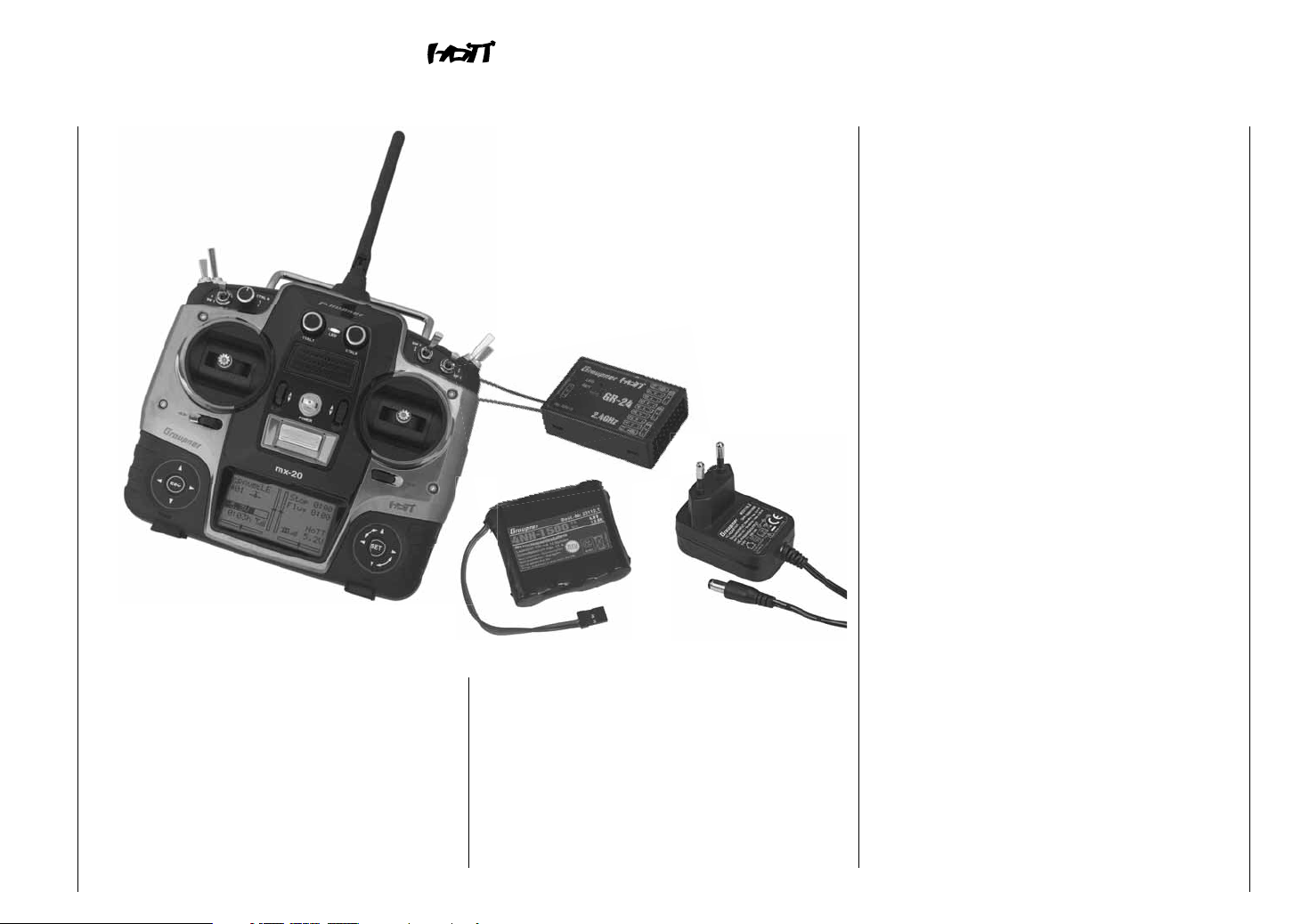
The Order No. 33124 set includes
Microcomputer transmitter mx-20 HoTT with built-
in NiMH transmitter battery 4NH-2000 RX RTU fl at
(change reserved), plug-in charger and Graupner
bidirectional receiver GR-24 HoTT.
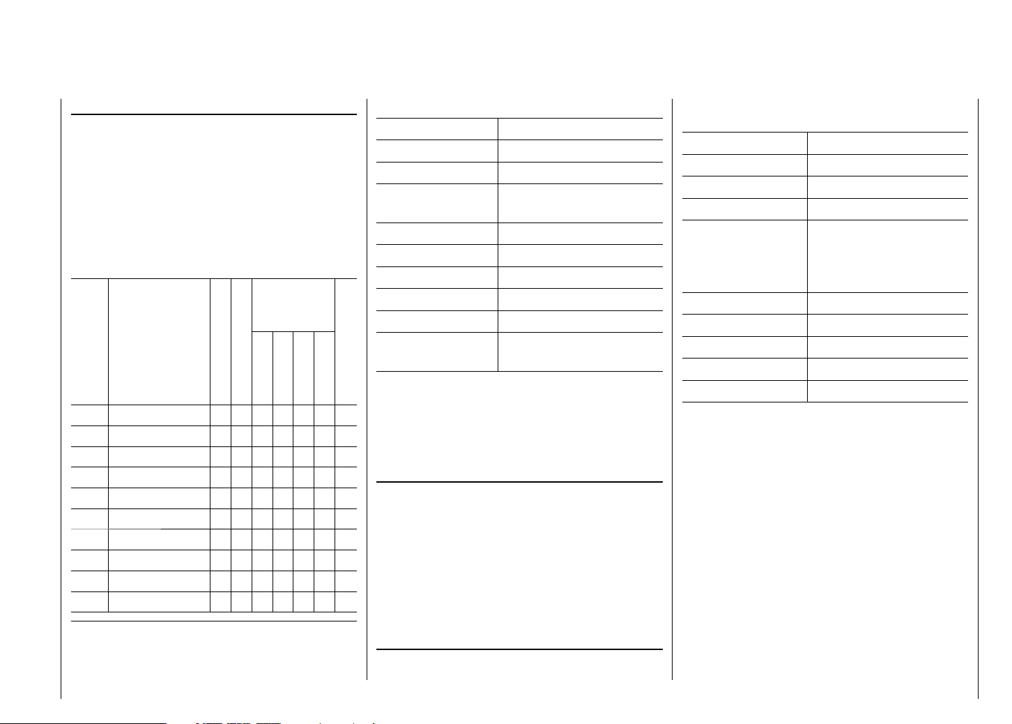
Recommended charger units (accessories)
appropriate for
the following
batteries
Order
No. Designation
Input voltage 220 V
Input voltage 12 V
NiCd
NiMH
LiPo
lead battery
6411 Ultramat 8 x x x x x
6463 Ultramat 12 plus x x x x x x
6424 Ultramat 14 plus x x x x x x x
6466 Ultra Trio plus 14 x x x x x x x
6468 Ultramat 16S x x x x x x x
6469 Ultra Trio Plus 16 x x x x x x
6470 Ultramat 18 x x x x x x x
6475 Ultra Duo Plus 45 x x x x x x x
6478 Ultra Duo Plus 60 x x x x x x x
6480 Ultra Duo Plus 80 x x x x x x x
Transmitter charger cable, order no. 3022 and receiver charger cable,
order no. 3021 are also needed to charge batteries.
Other charger units and details about the listed chargers can be found
in the Graupner RC main catalog or in Internet at www.graupner.de.
mx-20 HoTT technical data
Frequency band 2.4 … 2.4835 GHz
Modulation FHSS
Transmit power see country setting, page 227
Control functions 12 functions, 4 of these can
be trimmed
Temperature range -10 … +55 °C
Antennae collapsible
Operating voltage 3.4 … 6 V
Current draw about 180 mA
Dimensions about 190 x 195 x 90 mm
Weight about 770 g with transmitter
battery
integr. balancer
Accessories
Order No. Description
1121 Neck strap, 20 mm wide
70 Neck strap, 30 mm wide
3097 Hand transmitter wind protection
Teacher/pupil cable for mx-20 HoTT
see page 201
Replacement parts
Order No. Description
2498.4FBEC 4NH-2000 RX RTU fl at
33800 HoTT transmitter antenna
Technical data, receiver GR-24 HoTT
Order No. 33512
Operating voltage 3.6 … 8.4 V*
Current draw about 70 mA
Frequency band 2.4 … 2.4835 GHz
Modulation FHSS
Antenna Diversity antennas,
2 x about 145 mm long,
about 115 mm encapsulated
and about 30 mm active
Plug-in servos 12
Plug-in sensors 1
Temperature range about -10 … +55 °C
Dimensions about 46 x 31 x 14 mm
Weight about 16 g
* The specifi cation for permissible operating voltage range applies
only to the receiver. Please note in this context that receiver input
voltage is applied without regulation to connected servos but the
voltage range for most connectible servos (speed controls, gyros,
etc.) is only 4.8 to 6 V.
Other accessories are listed in the appendix or can
be found in Internet at www.graupner.de. Feel free
to contact your dealer too. He will be glad to provide
advice.
Introduction - Remote control set
13
Page 14
Operating notices
Transmitter power supply
The mx-20 HoTT transmitter has a highly capacitive,
rechargeable NiMH battery, 4NH-2000 RX RTU (Order
no. 2498.4FBEC), as standard equipment. (changes
reserved) However, the standard built-in battery is
not charged upon delivery of the transmitter.
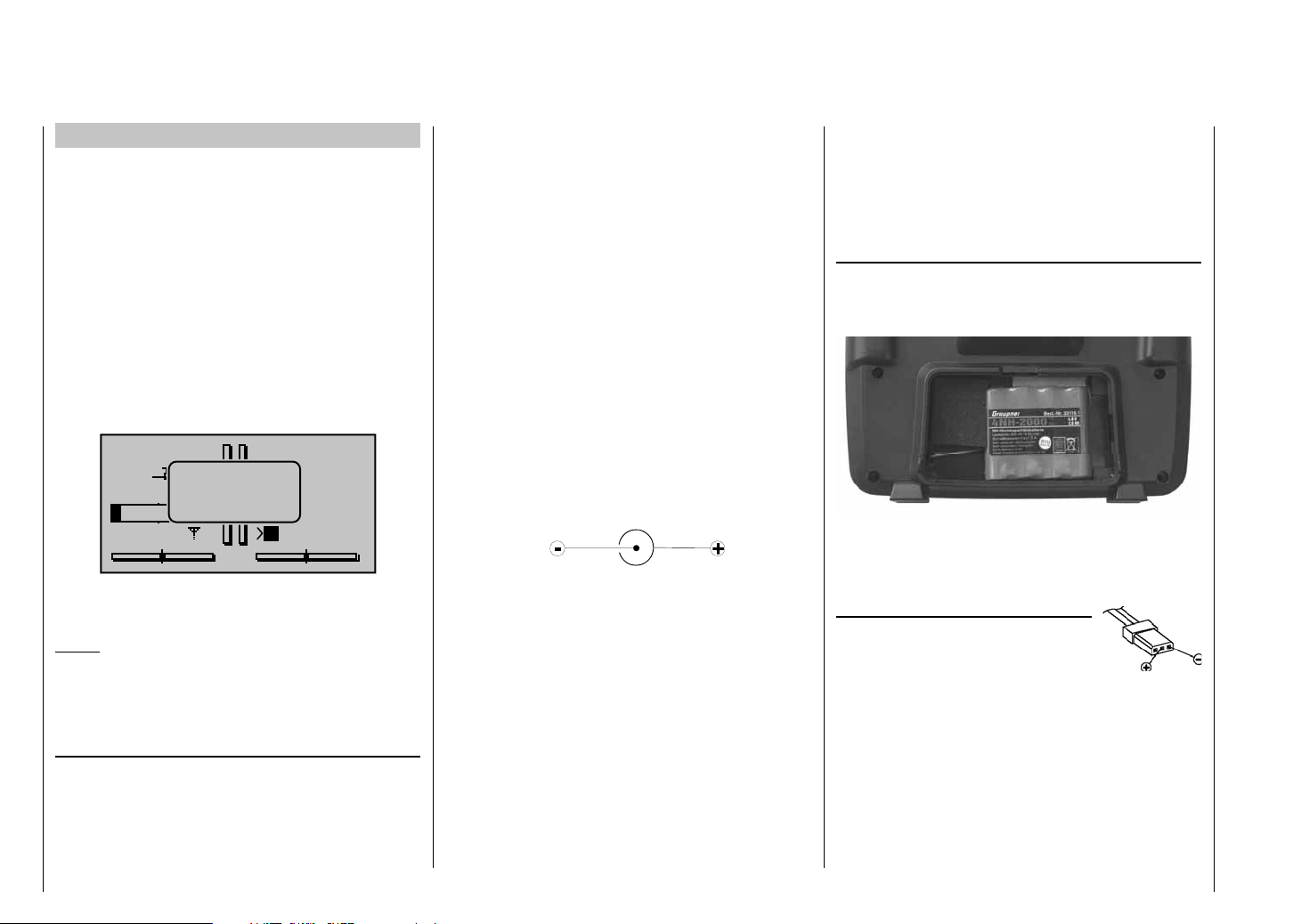
When the transmitter is used, its battery voltage
should be monitored by way of the indicators provided
in the LCD display. If battery voltage drops below
the adjustable voltage setting (set via item "Batterie
warning" in the "Basic Settings" menu, page 226,),
default value 4.7 V, an audible warning signal will sound
and the message window shown below will appear in
the screen
GRAUBELE
#01
0:22h
No later than now, operation must be terminated so the
battery can be charged again.
Notice:
Be sure that the correct battery type is set in the "Basic
Settings" menu, page 224! NiMH must be set as
standard.
Charging the transmitter's battery
The transmitter's rechargeable NiMH battery can be
recharged by connecting the charging jack located,
on the right side of the transmitter, with the included
charger (order no. 33116.2).
As a rule of thumb for charging time, an completely
Operating notices
14
4.6V
battery
needs
charging
10%
x
Stop
Flug
«normal »
K78
Mx
0:00
0:00
HoTT
0.0V
discharged battery will require 12 hours to recharge at a
current rate equal to one tenth of its specifi ed capacity.
For the standard transmitter battery and included
charger, this is a current rate of 200 mA. However,
you must yourself ensure that the charging process is
terminated when it should be …
The transmitter must be switched "OFF" during
the entire charging procedure. Never switch on the
transmitter when it is connected to the charger. Even
a brief interruption to charging can cause charging
voltage to rise to a level that will immediately damage
the transmitter with over-voltage. Also for this reason, be
sure all connectors are always plugged in securely and
have good contact.
mx-20 HoTT charging jack polarity
The charger cables on the market from other
manufacturers often have different polarities. Therefore use
only an original Graupner charger cable, order no. 3022.
Charging with automatic chargers
The transmitter's charger jack does come standard
with reverse polarity protection but nevertheless it can
be used with suitable chargers for quick charging the
transmitter's battery.
Set the quick charger unit, according to its manual, for
a delta peak voltage difference of 5 mV … 20 mV or
equivalent such that it is adapted for quick charging
NiMH cells
First connect the charger cable's banana plugs to
the charger and only then connect the cable's other
end into the charging jack on the transmitter. Never
allow the bare ends of the banana plugs to come
into contact with one another when the other end of
the cable is plugged into the transmitter. In order to
prevent damage to the transmitter, charging current
should never exceed 1 A. If necessary, limit the
current at the charger.
Removing the transmitter's battery
To remove the transmitter's battery, fi rst unlatch the
cover of the battery compartment on the rear side of the
transmitter housing then remove the cover.
Take out the transmitter's battery then disconnect the
transmitter battery's connector by carefully pulling on the
supply line cable.
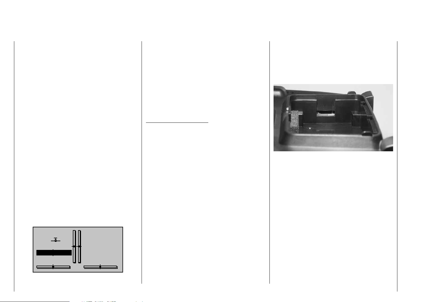
Inserting the transmitter's battery
Hold the transmitter battery connector
such that the black or brown cable is
oriented toward the antenna side and
the empty jack of the battery connector
is oriented toward the fl oor side then push the battery
connector in the direction of the board onto the three pins
sticking out out of the board inside the transmitter. (The
battery connector is protected against a reverse polarity
connection by two slanted edges, see illustration.)
Place the battery into its compartment and close the
cover.
Transmitter
connector polarity
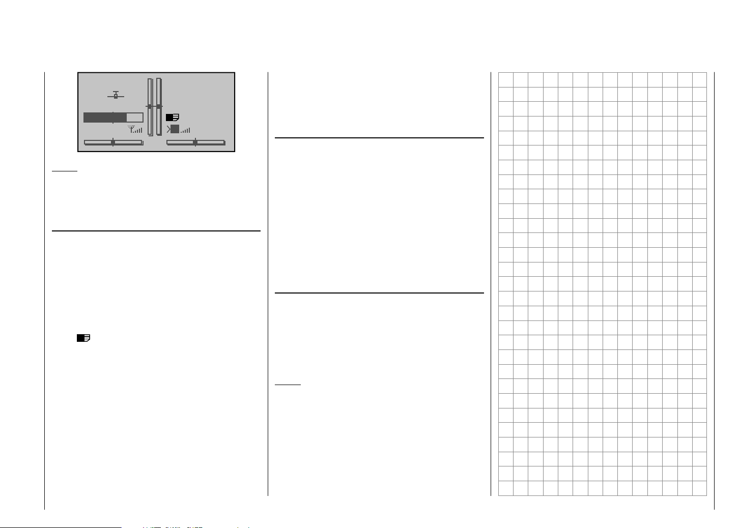
Page 15
Battery operation timer at the bottom left of the
screen
This timer shows the transmitter's cumulative operating
time since the transmitter's battery was last charged.
This timer is automatically reset to "0:00" when the
transmitter is switched on and its battery voltage is
signifi cantly higher than when the transmitter was last
used, e. g. because the battery was charged.
GRAUBELE
#01
5.9V
0:00h
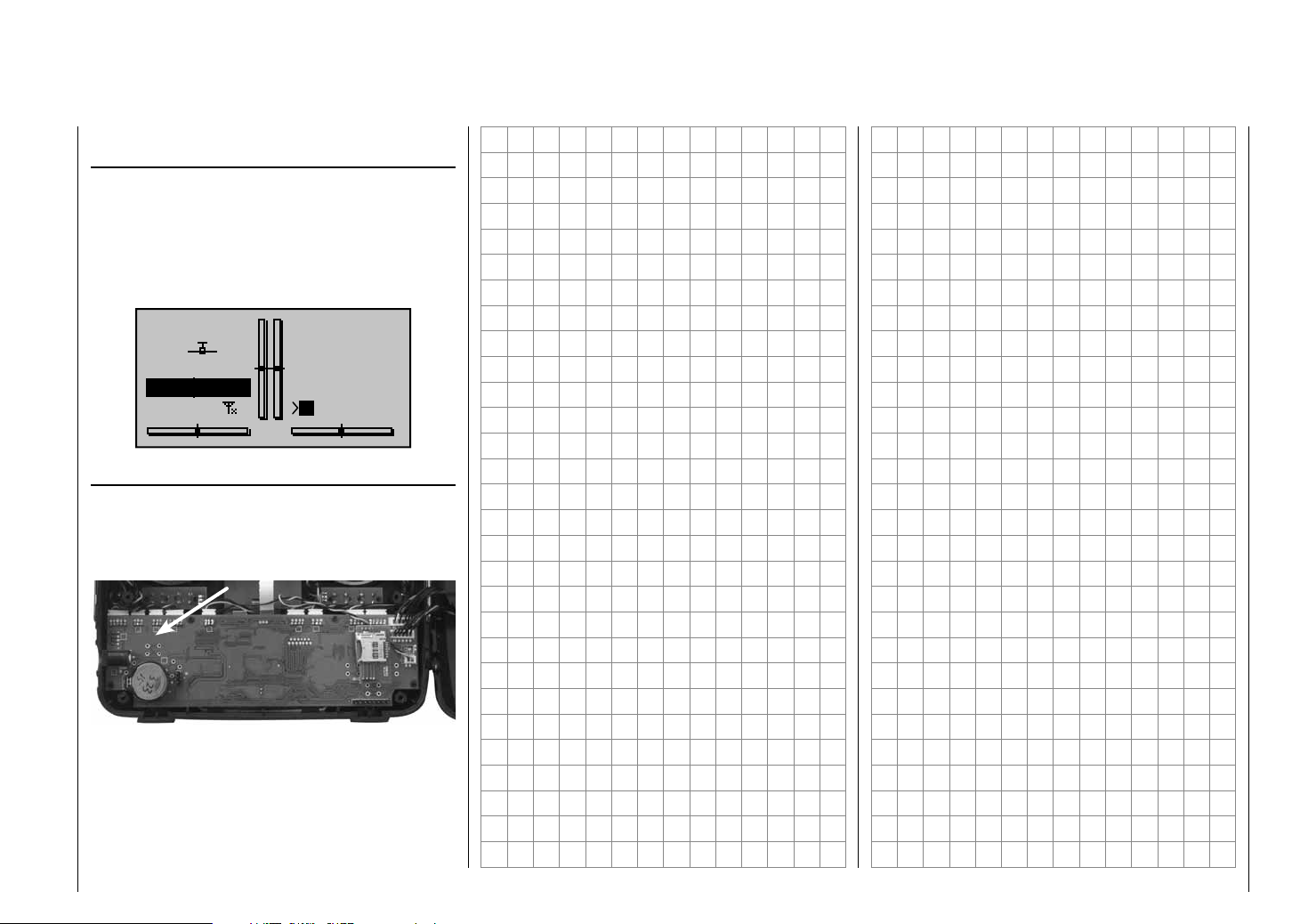
Lithium battery, CR 2032
At the left side of the transmitter board there is a fi xture
for a lithium battery. The user can replace this battery
when necessary with another lithium battery of type
CR 2032:
This battery maintains the date and time settings during
a transmitter power supply outage, for example when
the transmitter's main battery is being replaced.
Stop
Flt
«normal »
K78
Mx
0:00
0:00
HoTT
0.0V
Operating notices
15
Page 16
Operating notices
Receiver power supply
A selection of 4 and 5 cell NiMH battery packs having
different capacities are available to power the receiver. If
digital servos are in use, we recommend a 5 cell battery
pack (6 V) to afford adequate battery capacity. If analog
and digital servos are used in mixed operation, be sure
to pay attention to the given maximum permissible
operating voltage. A stabilized, adjustable power
supply for the receiver with 1 or 2 receiver batteries
can be provided, e. g. the PRX-unit, order no. 4136, see
appendix.
For reasons of safety, do not use battery boxes or dry
cell batteries.
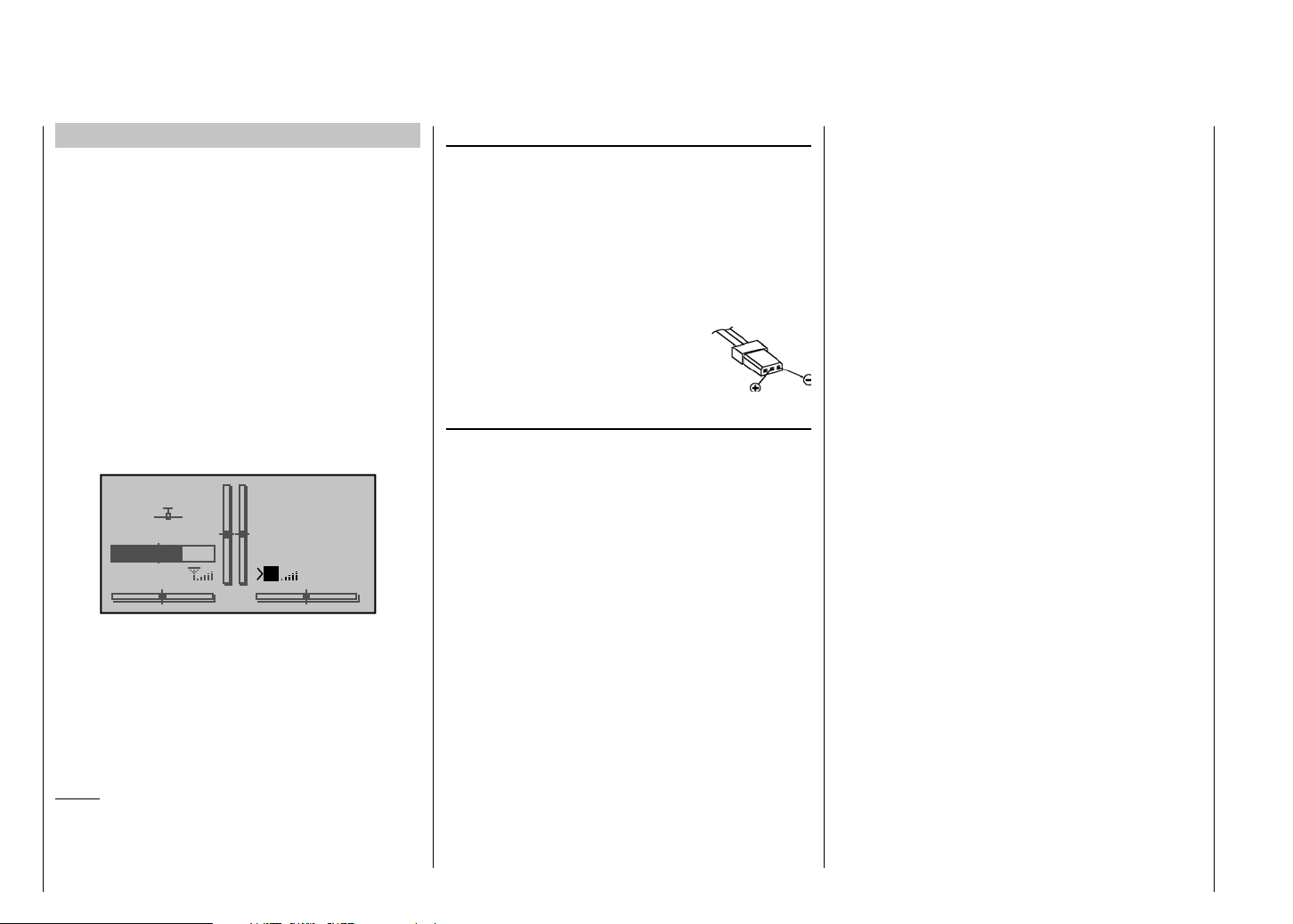
The voltage of the on-board power supply will be
displayed at the bottom right of the transmitter's screen
while the model is in operation.
GRAUBELE
#01
5.2V
2:22h
If the adjustable warning threshold (default value 3.8 V)
set in the Telemetry menu, see page 217, is underrun,
an optical and acoustic under-voltage warning will be
issued.
Despite this feature, be sure to check the condition
of the battery at regular intervals. Do not wait for the
warning to be issued before recharging the battery.
Notice:
An overview of available batteries, chargers and current
source test instruments can be found in the Graupner
RC main catalog or in Internet at www.graupner.de.
Operating notices
16
Stop
Flt
«normal »
K78
M
0:00
0:00
HoTT
5.5V
Charging the receiver battery
Charger cable, order no. 3021, can be plugged directly
onto the receiver's battery for charging. If the battery in
the model is connected by way of an order no. 3046,
3934, 3934.1 or 3934.3 power supply cable, then
charging can be accomplished via the charging jack or
special charging connector integrated into the switch.
The switch in the power supply cable must be in its
"OFF" position for charging.
Receiver battery connection polarity
General charging notices
The charging instructions for the charger as well as •
for the battery from its manufacturer to be observed.
Pay attention to the maximum permissible charging •
current specifi ed by the battery's manufacturer. In
order to prevent damage to the transmitter, charging
current should never exceed 1 A. If necessary, limit
the current at the charger.
If the transmitter battery is nevertheless to be •
charged at a current rate in excess of 1 A, then
it is imperative that this is done outside the
transmitter. Otherwise there is a risk of damage to
the transmitter's board due to overloading its printed
circuit paths and/or overheating of the battery.
If an automatic charger is to be used for charging, •
perform several test charging procedures to ensure
the fl awless functionality of its automatic shut-off.
This applies particularly if you want to charge the
standard installed NiMH battery with an automatic
charger unit intended for NiCd batteries Monitor the
charger's shut-off behavior if it has that option.
Do not execute a battery discharge or battery •
maintenance program through the charger jack. The
charger jack is not suitable for this purpose.
Alway connect the charger cable to the charger fi rst •
and then to the receiver or transmitter battery. This
avoids the possibility of shorting the bare banana
plug ends together.
If the battery heats up signifi cantly, check the •
battery's condition, replace the battery or reduce the
charging current.
Never leave a charging battery unattended.•
Follow the safety notices and handling •
instructions provided on page 8.
Page 17
Joystick length adjustment
The length of both joysticks can be continuously
adjusted to adapt these transmitter controls to the pilot's
preference.
Hold the lower half of the knurled grip in place then turn
the upper section to release its counter-locked threads.
Now pull up or push down on the joystick's end to the
desired length. When the length is suitable, tighten the
counter-locked threads of the upper and lower sections
again.
Opening the transmitter housing
Carefully read the notices below before opening the
transmitter housing. It may be better if unexperienced
users ask a Graupner Service location to take care of
the procedures described below.
The transmitter should only be opened in the following
situations:
to convert a neutralized joystick to a non-neutralized •
joystick or a non-neutralized joystick to a neutralized
joystick.
to adjust joystick return tension.•
Switch off the transmitter before opening its cover
(power switch to "OFF").
Open the battery compartment as described on the
previous double-page, remove the battery and if a micro
SD card is inserted be sure to remove it too.
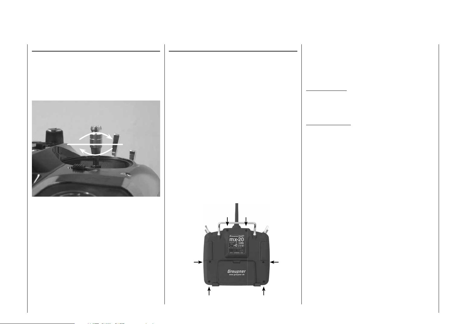
Once the battery and any micro SD card have been
removed, loosen the six countersunk screws on the rear
of the transmitter with a Phillips, size PH1, screwdriver,
see illustration.
Housing screw locations
Hold the two housing sections together by hand then
turn the transmitter upright over a suitable surface so
these 6 screws can fall out without getting lost. Now lift
up on the backplate carefully and turn it open to the right
like you would open a book.
A T T E N T I O N:
Two multi-conductor cables connect the backplate
with the transmitter electronics in the upper section.
These connections must not be damaged.
Important notices:
Make no modifi cations of any kind to the circuitry •
as this will void the guarantee as well as the
unit's offi cial permit.
Be sure not to touch the circuit boards with any •
metallic objects. Do not touch contacts with your
fi ngers.
Never switch the transmitter on when its housing •
is open.
When you close the transmitter again, be sure
that …
… no cables are caught between housing edges •
when the backplate is put into position.
… both housing parts are properly seated with one •
another before screwing them together. Never force
the housing sections together.
Turn the screws down into the existing housing •
threads without stripping them out.
… reconnect the battery.•
Operating notices
17
Page 18
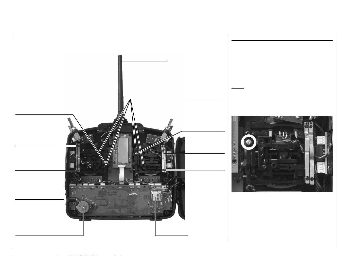
Operating notices
Do not touch the
circuit board!
Do not touch t
he circuit board!
left
joystick aggregate
right
joystick aggregate
neutralization screw
brake springs
collapsible antenna
adjustment screw for joystick restoration force
Do not touch t
he circuit board!
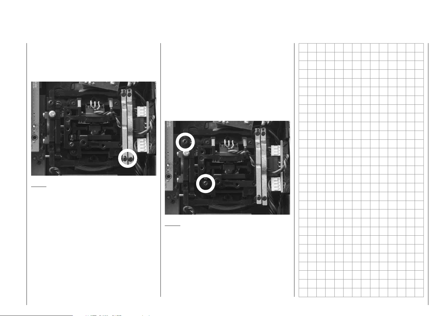
Converting joysticks
Neutralization
Both the left and the right joystick can be confi gured
for neutralized or non-neutralized operation as desired.
Open the transmitter housing as previously described.
To change the joystick's factory setting, locate the screw
shown in the fi gure below enclosed in a white circle.
Notice:
The aggregate for the right joystick is a mirror image of
the left joystick so the corresponding screw for the right
joystick is on the right side just below the middle.
neutralization screw
brake springs
adjustment screws
Charger jack
user-replaceable
CR2032 lithium battery to buffer the
integrated realtime clock
Operating notices
18
right
joystick aggregate
Do not touch the
circuit board!
left
joystick aggregate
Slot for
memory cards
adjustment screws
Now turn this screw down until the respective joystick
is free to move from limit to limit - or turn the screw out
until the joystick again completely self-restoring.
Page 19
horizontal
vertical
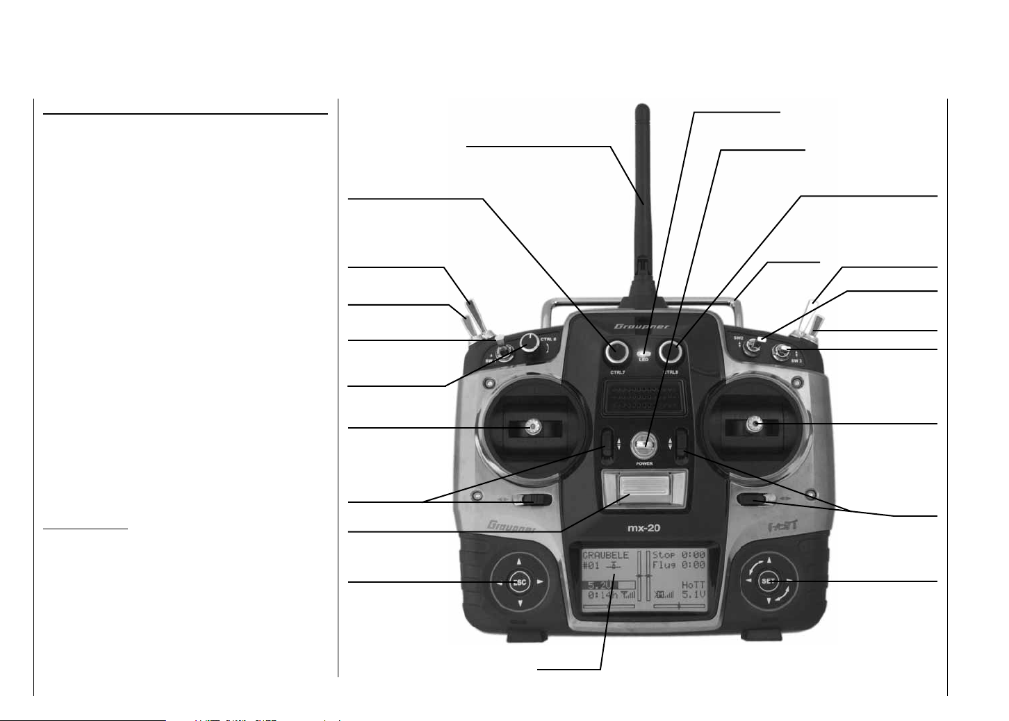
Brake spring and ratchet
The outboard screw of the two marked in the next fi gure
adjusts the braking force and the inboard screw adjusts
the strength of the ratchet for the respective joystick.
Notice:
The aggregate for the right joystick is a mirror image of
the left joystick so corresponding screws for the right
joystick are located at the top left.
Joystick restoring force
The joystick's restoring force can also be adjusted to the
pilot's preference. The adjustment is located next to the
return springs, see markings in the fi gure below.
Spring force for the given direction of motion can be
adjusted by turning the respective screw with a Phillips
screwdriver.
Right turn (clockwise) = return harder,•
Left turn (counter clockwise) = return softer.•
vertical
horizontal
Notice:
The aggregate for the right joystick is a mirror image of
the left joystick so corresponding screws for the right
joystick are located to the right of the middle.
Operating notices
19
Page 20
Transmitter description
Transmitter operating elements
Attaching the transmitter's neck strap
There is an eyelet on the top side of the mx-20 HoTT
transmitter (see fi gure at the right) to which a neck strap
can be attached. This anchor point has been chosen
because the transmitter is optimally balanced here when
it hangs from the strap.
Order No. 1121 Neck strap, 20 mm wide
Order No. 70 Neck strap, 30 mm wide
Important notice:
In its delivered confi guration, the transmitter can only
operate any servos attached to the receiver by way
of the two joysticks. For reasons of fl exibility, all other
operating elements (CTRL 6 … 8, SW 1 … 9) are
designated as "free" by the software. These other
operating elements can be freely assigned to actuators
as described in the text for the "Control adjust" menu
on page 96 (winged aircraft models) or page 100
(helicopter models).
Transmitter description
20
antenna with kink and twist joint
proportional speed control CTRL 7
2 position switch SW 8
3 position switch
SW 4/5 or CTRL 9
2 position momentary
contact switch SW 1
proportional speed
control CTRL 6
left joystick
trimmer
ON/OFF switch
left touch pad
LC display
main status LED
eyelet for neck strap
proportional speed control CTRL 8
carrying handle
2 position momentary
contact switch SW 9
2 position switch SW 2
3 position switch
SW 6/7 or CTRL 10
2 position switch SW 3
right joystick
trimmer
right touch pad
Page 21
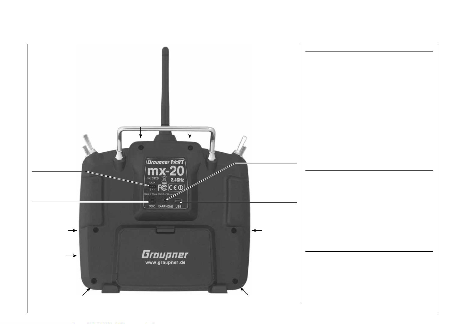
Transmitter rear side
Data jack for connecting
the Smart-Box, Order
No. 33700
DSC jack for connecting
fl ight simulators and for
teacher/pupil mode
housing screw
housing screw
housing screw
earplugs or
headset connector
fi ve-pole mini USB
socket for connecting
the transmitter to a PC
housing screw
Headset connector
The jack centered in the lower portion of the type
plate on the back of the transmitter is for connecting
conventional earplugs or a headset by way of a 3.5 mm
audio plug. (not included in the set)
The transmitter's acoustic signals as well as those
signals associated with the telemetry menu are output
via this connection. These announcements are made in
German language by default. More details about "Voice
output" can be found in the section "HIDDEN MODE"
beginning on page 28 and "Telemetry" beginning on
page 208.
The headset connector's volume control can be adjusted
in the "Voice volume" line of the "Basic Settings" menu,
see page 227.
Mini-USB connector
This connector socket is used to establish a connection
between the transmitter and a PC running a Windows
operating system (XP, Vista or Windows 7). The PC
software required, such as a suitable USB driver, can be
found on the download page for the given product on the
Graupner website at www.graupner.de.
Once the necessary software is installed on the PC, this
USB connection can be used to update the transmitter
or even just to set the date and time in the transmitter.
Charger jack for
transmitter battery
housing screw
battery compartment cover
housing screw
Data jack
For connecting the optionally available Smart-Box,
Order No. 33700.
Details about the Smart-Box can be found with the given
product in the Graupner RC main catalog or in Internet
at www.graupner.de.
Transmitter description
21
Page 22
DSC
Direct Servo Control
The acronym "DSC" is a carryover which stands for the
original "Direct Servo Control" function. However, in
HoTT systems the "direct servo control" function is no
longer available via a diagnose cable due to technical
reasons.
The standard two-pole DSC jack in the mx-20 HoTT
transmitter is used as the teacher or pupil jack as well
as an interface to fl ight simulators.
To ensure a proper DSC connection, please observe:
Make any necessary menu changes.
Refer to the section beginning on page 198 to
adapt the mx-20 HoTT transmitter to a teacher/pupil
system.
When operating a fl ight simulator or when operating 1.
the mx-20 HoTT transmitter as a pupil transmitter,
ALWAYS leave the transmitter's ON/OFF switch
in the "OFF" position as only in this position does
the transmitter's RF module remain inactive after
the DSC cable is inserted. This also reduces the
transmitter's power consumption somewhat.
The main status LED should now constantly
illuminate red and the transmitter's basic setup
screen should show the string "DSC pupil" on the
right just below the middle timer. At the same time,
the display of telemetry indicators will be suppressed.
PUPIL
#11
5.9V
0:01h
Stop
Flt
DSC
«normal »
0:00
0:00
HoTT
0.0V
Thus the transmitter is ready for operation.
To the contrary, teacher mode for the mx-20 HoTT
transmitter requires that the transmitter be switched
on prior to plugging in the respective cable.
Connect the other end of the cable to the desired unit 2.
in compliance with the given operating instructions
for that unit.
Important:
Be sure that all connectors are seated fi rmly in
their respective sockets.
Notice about fl ight simulators:
Because of the myriad of fl ight simulators available on
the market, it may be necessary to have the contact
layout of the audio plug or DSC module appropriately
modifi ed by Graupner Service.
Data storage
Card slot
micro SD and micro SDHC
With the mx-20 HoTT transmitter switched off,
removing the battery compartment cover and the
transmitter's battery will make the card slot accessible
(located in the right sidewall of the battery compartment).
This card slot is intended for micro SD and micro SDHC
type memory cards.
All conventional micro SD memory cards up to 2 GB and
micro SDHC cards up to 32 GB storage capacity can
be used. However, as a manufacturer we recommend
the use of memory cards no larger than 4 GB as this is
completely adequate for all normal situations.
The type of memory card referred to here became
known in conjunction with digital cameras and cell
phones. It is to be pushed into the slot with its contacts
upward, front facing the rear wall and latched in position
there. After re-installing the battery and closing the
battery compartment, the transmitter can be switched on
again. The stylized image of a memory card will appear
in the basic setup screen to indicate the presence of the
inserted memory card.
Transmitter description
22
Page 23
GRAUBELE
#01
5.2V
3:33h
Notice:
If a micro SD card is inserted, be sure to remove
it BEFORE taking off the transmitter's backplate.
Otherwise there is a risk of damaging the memory card.
Data acquisition / storage
The storage of data on the SD card is coupled to the
fl ight timer. If this timer is started – when a suitable
memory card is inserted in the card slot and a telemetry
link to the receiver exists – both the timer and data
acquisition will stop when the fl ight timer is stopped. The
fl ight timer is started and stopped as described in the
section "Timers (general)" on page 138.
While data acquisition is ongoing, the on-screen card
image will blink continuously at a slow rate.
The amount of data written on the memory card is
presented as a black bar graph which grows from left to
right as data fi lls the memory card.
After a data acquisition session is fi nished, there will
be an (empty) folder "Models" and a "LogData" folder
on the memory card. Within the "LogData" folder there
will be log fi les in sub-folders that are designated with
names in the format 0001_year-month-day.bin, 0002_
year-month-day.bin, etc. If a model memory folder is still
"unnamed" when the memory card is removed from the
transmitter and inserted into the card slot of a PC or
laptop, the respective log fi les can be found in a sub-
Stop
Flt
«normal »
K78
M
0:00
0:00
HoTT
5.5V
folder designated "NoName". There is a PC program
available on the transmitter's download web page at
www.graupner.de with which the stored data can be
evaluated on a compatible PC.
Importing voice fi les
As already mentioned in the section "Headsets" on
page 21, this connection can also be used to output
the transmitter's acoustic signals as well as those
signals and announcements associated with telemetry
menu settings. These announcements are made in
German language by default. These announcements
are summarized in a voice packet which is stored in a
transmitter-internal memory but they can be replaced
by a voice packet of a different language at any time.
More information about this can be found in the section
"HIDDEN MODE" beginning on page 28.
Importing/exporting model memories
Any model memory can be stored to an inserted memory
card or from an inserted card into the transmitter. This
feature is intended to support data exchange between
identical transmitters or even use as data backup.
More information about this can be found in the section
"Copying/deleting" beginning on page 64.
Notice:
Some special symbols that can be used in model names
are subject to specifi c restrictions associated with the
FAT or FAT32 fi le system used by the memory cards and
these special symbols will be replaced during the copy
process with a tilde (~).
Transmitter description
23
Page 24
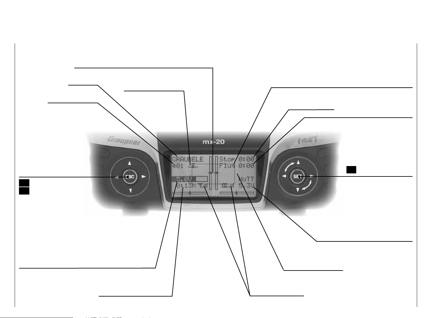
Display and keypad
optical indication of trim lever positions or, during activation
of speed controls CTRL 7 + 8, an alternative display of the
current positions of these controls
Model name
Memory location 1 … 24
left touch pad
paging
simultaneously pressed:
Change to the servo
display menu
ESC = cancel/return
ESC touched for about 1 s:
Change to the Telemetry menu
and return to basic display
Battery voltage and charge state bars
(if the preset threshold voltage is underrun, a warning will
appear – see "Warnings" on page 36 –, and an acoustic
warning tone will sound)
Model type indicator
(winged aircraft / helicopter)
Stopwatch in min:s
(upward/downward)
Receiver power supply voltage
Flight phase name
switchover between
fl ight phases by switch
possible warnings, see page 36
Flight timer in min:s
(upward/downward)
right touch pad:
Paging / changing values
SET select / confi rm
simultaneous pressing of
or = CLEAR
Battery time since last
re-charge in h:min
Transmitter description - Display and keypad
24
Signal strength indicator
Page 25
Operating the "data terminal"
Entry keys ESC and SET
Display symbols
Displayed telemetry symbols
the active model memory has not yet "bonded"
with a HoTT receiver. More about the "Binding"
process, see page 69 or 75.
non-blinking: Switched off on RF transmitter side
blinking antenna symbol:
The last receiver bound to the active model is
inactive or out of range
>M x no telemetry signal to receive
>M signal strength indicator
>P indicator for pupil signal strength on the teacher
transmitter display
Keys left of the display
ESC• key
brief repeated pressing the ESC key will cause a
stepwise return to the function selection screen or
even further to the base screen. Any changes made
to settings remain.
Momentarily touching the ESC key for about 1 s
while in the base screen will open and close the
Telemetry menu.
arrow keys •
Momentarily pressing one of these keys will cause 1.
analogous paging in the given arrow direction
through lists, e. g. through the model selection list
or the multi-function list or within menus though
the menu's lines.
Simultaneous pressing on 2. will change the
transmitter's base screen and almost any menu
position to the "Servo display" menu.
Keys to the right of the display
SET• button
After switching the transmitter on, briefl y pressing 1.
the
SET key will cause a jump from the displayed
base screen to the Multi-function menu. In the
same manner a selected menu can now be called
up with the SET key.
Momentarily pressing the 2. SET key from within
the Basic Settings menu will activate / deactivate
(confi rm) the given setting fi elds.
arrow keys •
1. "Paging" through the Multi-function menu and
the menu lines within the Basic Settings menu
analogous to the arrow keys of the left touch pad.
2. Select or set parameters in setting fi elds after they
have been activated by briefl y touching the SET
key, whereby the keys and are used for
the same corresponding functions. In this case it
is completely irrelevant which of these two keys
are used.
By briefl y pressing the 3. keys simultaneously
or an altered parameter value for the active
entry fi eld will again be restored to its default
value (CLEAR).
Notice:
Touching the given touch pad does not itself initiate •
the given action but rather the end of the touch.
In the event the touch pads do not exhibit any •
functionality immediately after switching the
transmitter off and then on again right away, this is
not a fault. Just switch the transmitter off again then
wait for several seconds before switching it on again.
Transmitter description - Display and keypad
25
Page 26
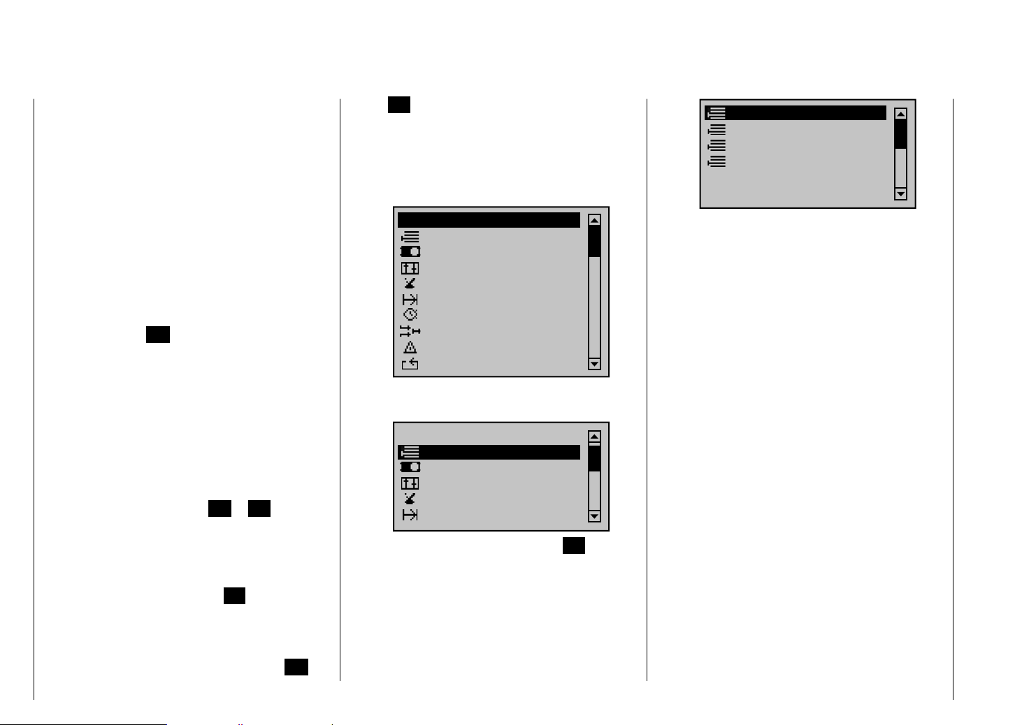
Shortcuts
The following key combinations can be used to directly
call up certain menus and options:
CLEAR•
Brief simultaneous activation of the keys or
on the right touch pad will restore the active
entry fi eld's changed parameter value back to its
default value.
"• Servo screen"
Brief simultaneous activation of the keys of the
left touch pad will cause a jump from the transmitter's
base screen or from almost any menu position to the
"Servo" menu, see page 230.
"• Telemetry" menu
Press the center
about 1 s to call up the "Telemetry" menu from the
transmitter's base screen, see text beginning on
page 208, or to return to the base screen again.
Graphic display of telemetry data•
Briefl y touching one of the arrow keys of the left
or right touch pad will cause a jump from the base
screen directly to the transmitter's graphic display
of telemetry data or will allow paging back and forth
between individual graphic displays.
Briefl y touching the centered ESC or SET key will
cause a return back to the base screen.
"• HIDDEN MODE"
(language selection and contrast)
Press and hold arrow keys of the left touch
pad then momentarily touch the SET key of the right
touch pad, see next double-page.
Entry lockout•
Entry lockout is activated and deactivated from the
base screen by simultaneously pressing the ESC
ESC key in the left touch pad for
and SET keys for a little longer (about 2 s).
Quick-Select•
From the multi-function list, a jump can be made to a
"Structure overview" by a brief, simultaneous touch
on the or keys of the right touch pad.
Menus are arranged in clear groups in this overview.
All menus
Memory
Servo settings
Transm. controls
Switches
Flight phases
Timers
Mixers
Special funct.
Global functions
Now the desired group can be selected with the
arrow keys of the left or right touch pad …
All menus
Memory
Servo settings
Transm. controls
Switches
Flight phases
… and then briefl y touching the center SET key in
the right touch pad. As soon as the key is released,
only the respective generic term for the given menu
will remain listed. For example:
Model select
Copy / Erase
Suppress menus
Suppress models
Transmitter description - Shortcuts
26
Page 27
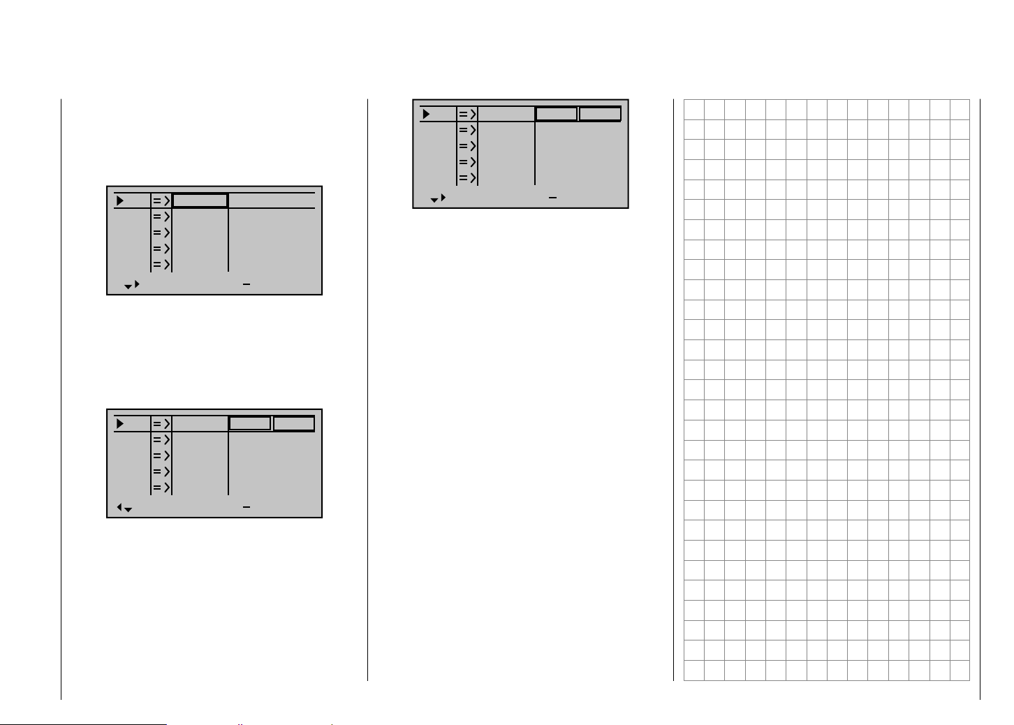
Concealed menu columns
Some menus have concealed columns to improve
legibility. Menus with concealed columns can be
recognized by virtue of a triangle pointing to the right in
the bottom left corner of the screen. For example, in the
menu "Servo settings":
S1
S2
S3
S4
S5
Rev cent
In this menu, e. g. the column "lim" +" (servo travel limit)
to the right of column "- travel +" is "concealed".
To reach this column, use the pointing triangle at the
bottom left of the screen to push the frame marker with
the arrow key of the left or right touch pad to just
beyond the column for "- travel +":
S1
S2
S3
S4
S5
Rev cent
0%
0%
0%
0%
0%
0%
0%
0%
0%
0%
100%
100%
100%
100%
100%
150%
150%
150%
150%
150%
100%
100%
100%
100%
100%
trv
150%
150%
150%
150%
150%
lim
+
+
S1
S2
S3
S4
S5
Rev cent
This procedure is analogous for the other menus.
0%
0%
0%
0%
0%
100%
100%
100%
100%
100%
100%
100%
100%
100%
100%
trv
+
To again return to the now-concealed column "- travel
+" or even further to the left, push the frame marker with
arrow key of the left or right touch pad appropriately
to the left:
Transmitter description - Concealed menu columns
27
Page 28
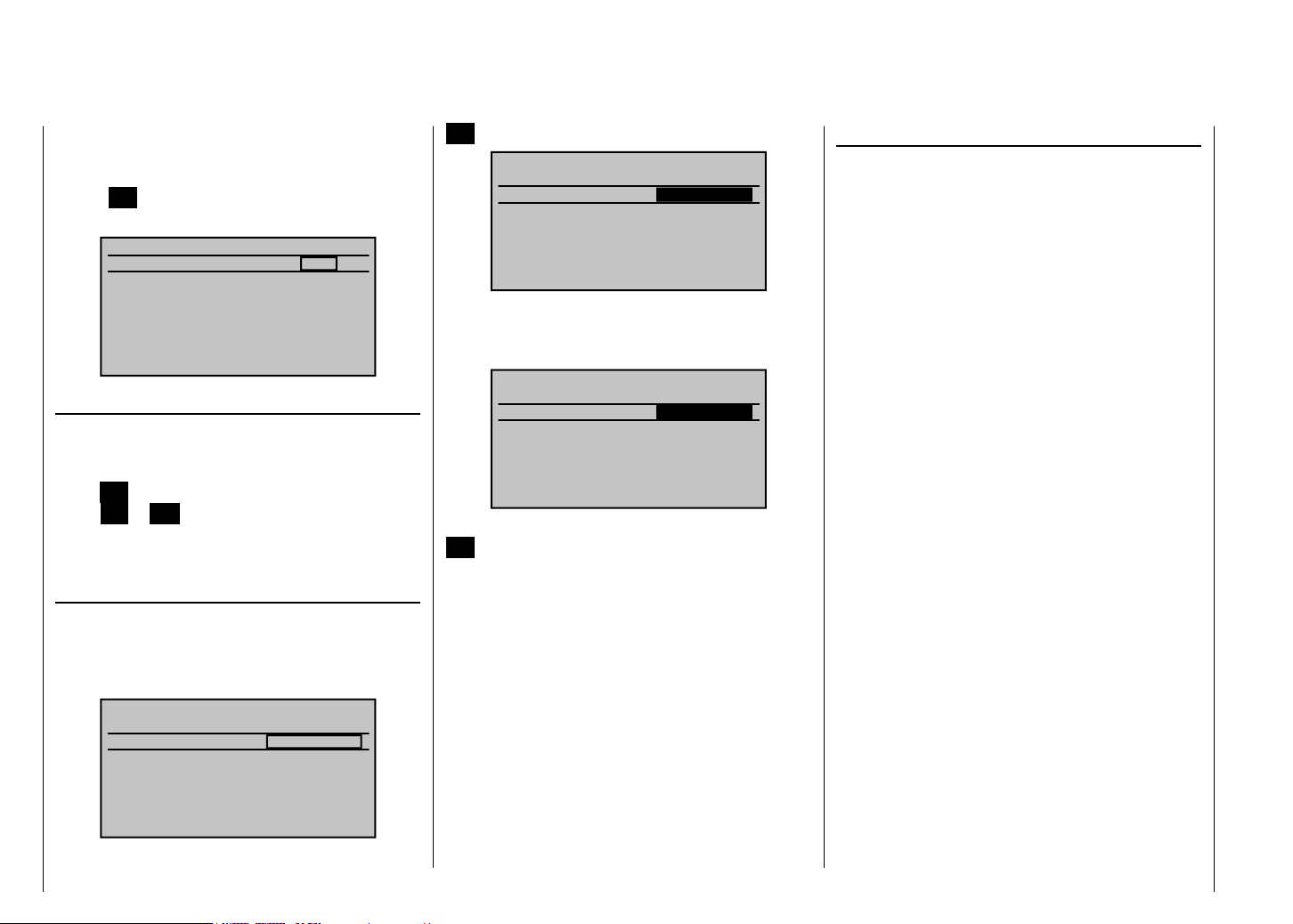
HIDDEN MODE
Language selection and display contrast
The mx-20 HoTT transmitter's "HIDDEN MODE" can
be reached from almost any menu position by pressing
and holding the arrow keys of the left touch pad
SET key of the right touch pad for about one
and the
second until the screen shown below is displayed.
HIDDEN MODE
CONTRAST
LANGUAGE
VOICE
STICK CALI.
CONTRAST
The screen's contrast characteristic can be adapted as
needed in this screen's "CONTRAST" line, as described
in more detail on pages 226/226, by tapping on the
center SET key of the right touch pad. Tapping again
on the SET or ESC keys will cause a return to line
selection.
The line …
LANGUAGE
… can be reached by tapping arrow key in the left
or right touch pad. One of the transmitter's available
languages can then be selected from the screen which
appears.
HIDDEN MODE
CONTRAST
LANGUAGE
VOICE
STICK CALI.
Activate language selection by pressing on the center
Transmitter description - Hidden mode
28
0
DEUTSCH
DEUTSCH
0
DEUTSCH
DEUTSCH
SET key in the right touch pad.
HIDDEN MODE
CONTRAST
LANGUAGE
VOICE
STICK CALI.
0
DEUTSCH
DEUTSCH
Now the default language "GERMAN" can be replaced
with the desired language by making a selection with the
arrow keys of the right touch pad. For example:
HIDDEN MODE
CONTRAST
LANGUAGE
VOICE
STICK CALI.
0
ENGLISH
DEUTSCH
Confi rm the selection by tapping again on the center
SET key in the right touch pad. All settings stored in the
transmitter remain intact after a change of language has
been made.
The following languages are available for selection at
the time this handbook was printed:
German•
English•
French•
The Italian and Spanish languages are planned for
inclusion at a later point in time. These will then be
made available by way of an update download from the
transmitter's web page at the Graupner website
www.graupner.de.
VOICE TRIGGER
As mentioned in section "Headsets" on page 21, the
transmitter's acoustic signals as well as those signals
and announcements associated with the telemetry
menu can be output by way of the headset connector.
These announcements are made in German language
by default. These announcements are summarized in
a voice packet which is stored in a transmitter-internal
memory but they can be replaced by a voice packet of a
different language at any time.
The following languages are available for selection at
the time this handbook was printed:
German•
English•
French•
The Italian and Spanish languages are planned for
inclusion at a later point in time. These will then be made
available on the transmitter's download web page at the
Graupner website www.graupner.de.
The given active language packet can then be swapped
out either with the PC program (also available as a
download from the transmitter's web page at
www.graupner.de) or per SD card as described below.
Preparation
If not already done, insert the SD card or SDHC card
into the transmitter as described on page 22. Now
when the transmitter is switched on it will perform
some operations which will include the creation of a
"VoiceFile" on the memory card.
Take this memory card, which has now been prepared
by the transmitter, out of the transmitter and insert it
into a suitable card reader. If necessary, attach the card
reader to your PC or laptop. Now copy the language
Page 29
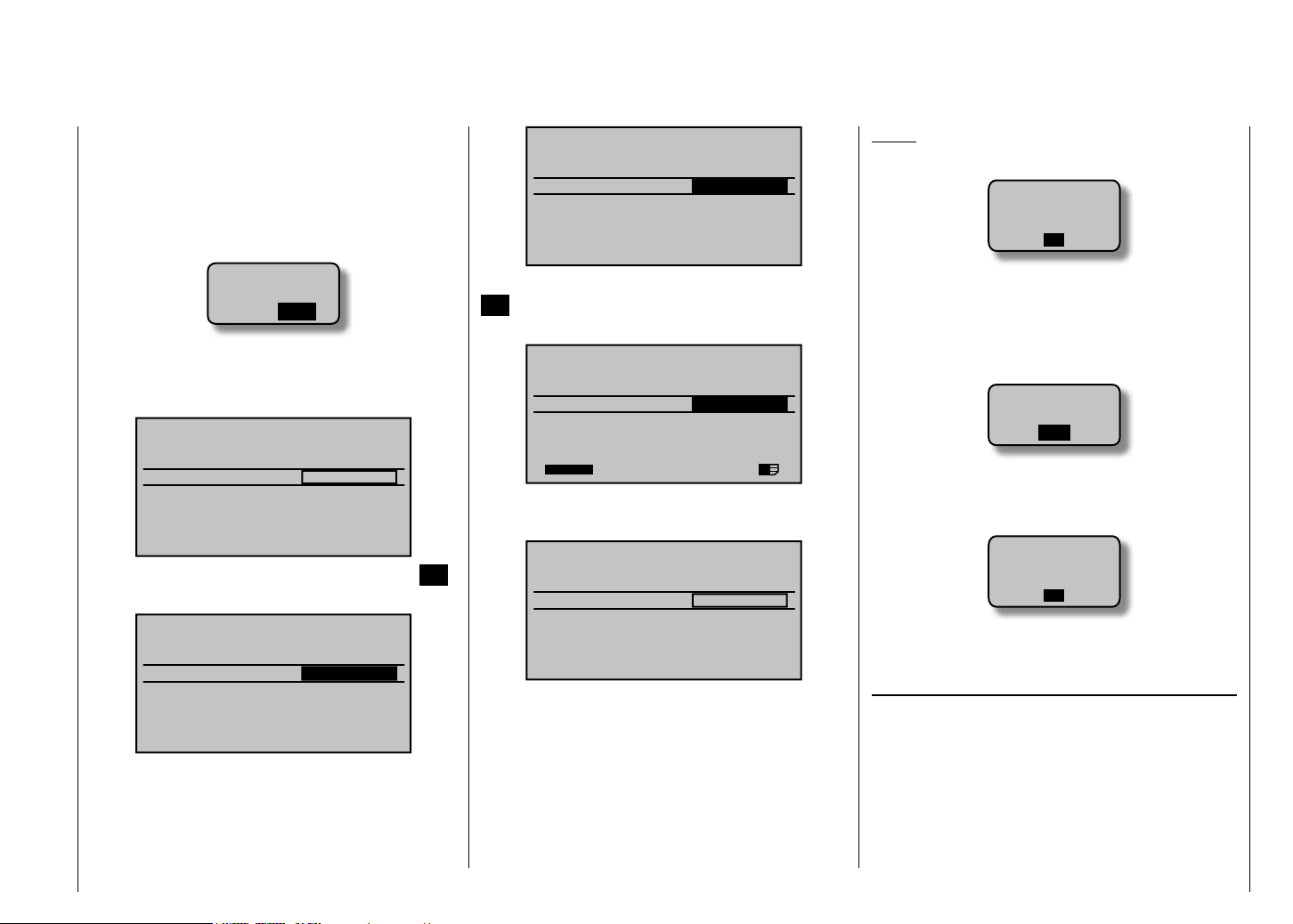
packet downloaded from the transmitter's web page (e.g.
"voice_gb.vdf") into the folder created by the transmitter.
Now take the memory card out of the card reader and
re-insert it into the transmitter. Once the memory card is
inserted in the transmitter, switch the transmitter on with
RF switched off.
HIDDEN MODE
CONTRAST
LANGUAGE
VOICE
STICK CALI.
0
ENGLISH
ENGLISH
Notice:
If the warning …•
RF
MUST BE
OFF
OK
Please select
RF on/off?
ON
OFF
Language change
Use the left or right arrow touch key to select the line
"VOICE".
HIDDEN MODE
CONTRAST
LANGUAGE
VOICE
STICK CALI.
0
ENGLISH
DEUTSCH
Activate language selection by pressing the center SET
key in the right touch pad.
HIDDEN MODE
CONTRAST
LANGUAGE
VOICE
STICK CALI.
0
ENGLISH
DEUTSCH
Now use the right touch pad arrow keys to replace the
default language "DEUTSCH" with the language you
want. For example:
Confi rm your selection with another tap on the center
SET key in the right touch pad. The selected language
packet will be loaded into the transmitter's memory.
HIDDEN MODE
CONTRAST
LANGUAGE
VOICE
STICK CALI.
22/100%
0
ENGLISH
ENGLISH
I
The loading process is fi nished as soon as the progress
bar at the lower edge of the display disappears.
HIDDEN MODE
CONTRAST
LANGUAGE
VOICE
STICK CALI.
0
ENGLISH
ENGLISH
When this process is fi nished, switch off the transmitter.
All settings stored in the transmitter remain intact after a
change of language has been made.
… appears, then the transmitter's RF radiation is still
active. Jump to the "Basic settings" menu, select
the "RF transmit" line, select its "OFF" option and
then repeat the procedure
If the warning …•
SD-CARD
INSERT
OK
… appears then the transmitter does not detect a memory
card in its card slot or the card found cannot be read.
If the warning …•
MISSING
IMPORT
DATA
OK
… appears then the transmitter could not fi nd an
appropriate fi le on the inserted memory card.
JOYSTICK CALIBRATION
If you feel the neutral position of your self-calibrating
joysticks (controls 1 … 4) are not exactly 0 % of
their control travel, then this can be checked and, if
necessary, corrected as follows.
Jump to the "Model select" menu and initialize a free
model memory as described on page 60. Whether the
model to be initialized is a winged aircraft or a helicopter
is irrelevant.
Transmitter description - Hidden mode
29
Page 30
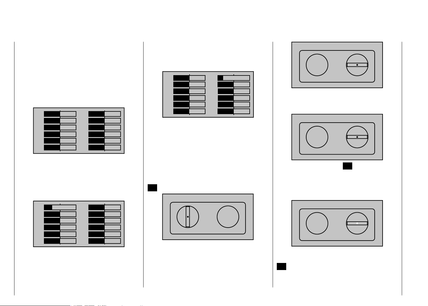
Wait for the notices which typically appear in the base
screen following a model change then jump to the
"Servo display" menu, for example by simultaneously
touching the keys of the left touch pad (WITHOUT
any interim change to trim settings or other program
settings).
If all four of your transmitter's joystick functions are still
self-neutralizing, this display should ideally look like the
one shown below.
11
1
3
5
7
9
–100 %
+
0%
0%
0%
0%
0%
2
4
6
8
12
0%
0%
0%
0%
0%10
0%
+
Otherwise the graph bars show current setting
percentages for joystick control functions which are not
self-neutralizing – typically for the "K1", throttle/brake or
throttle/pitch, control stick. For example, if the throttle/
brake control stick is in its "quarter-throttle" position, the
display would appear as shown below.
11
–50%
1
3
5
7
9
0%
0%
0%
0%
0%
+
2
4
6
8
12
0%
0%
0%
0%
0%10
0%
+
One after the other, put both joysticks into each of their
four possible limit positions without exerting force at
the limit position. In each of these eight possible limit
positions, the – side dependent – indication for exactly
-100 % or +100 % should be displayed. For example,
if Control 2 is at its left limit and the other three joystick
functions are in their respective middle positions then
your transmitter's display should look like the one shown
below.
11
1
3
5
7
9
0%
0%
0%
0%
0%
0%
+
12
2
4
6
8
–100 %
+
0%
0%
0%
0%10
0%
Regardless of the number of self-neutralizing joystick
functions available on your transmitter, if these checks
produce four 0 % results and eight 100 % results then
your transmitter's joysticks are optimally calibrated. You
can terminate this process then, if appropriate, delete
the model memory just created.
Otherwise jump (as described at the outset of the
previous double page) to the "Stick cali." line in the
"HIDDEN MODE" menu then briefl y touch the center
SET key in the right touch pad.
STICK CALIBRATION
CONTRAST
LANGUAGE
VOICE
STICK CALI.
0%
0
ENGLISH
DEUTSCH
The arrow keys of the right touch pad will now
allow you to cyclically select the four calibrated joystick
planes, e.g. the left/right plane of the right joystick.
STICK CALIBRATION
CONTRAST
LANGUAGE
VOICE
STICK CALI.
0%
0
ENGLISH
DEUTSCH
Now position the right joystick – without exerting extra
force – to its left limit corresponding with the on-screen
blinking arrow pointing to the left.
STICK CALIBRATION
CONTRAST
LANGUAGE
VOICE
STICK CALI.
+100%
0
ENGLISH
DEUTSCH
… and briefl y touch the center SET key in the right
touch pad. This concludes this example calibration of the
right joystick's left limit. The circle in the middle of the
stylized joystick plane will now blink as confi rmation of
the calibration.
STICK CALIBRATION
CONTRAST
LANGUAGE
VOICE
STICK CALI.
+100%
0
ENGLISH
DEUTSCH
Now release the self-neutralizing joystick so it can return
to its center position and then tap again on the center
SET key to calibrate the joystick's centered position. The
right arrow marker will begin to blink.
Transmitter description - Hidden mode
30
Page 31

STICK CALIBRATION
CONTRAST
LANGUAGE
VOICE
STICK CALI.
0%
0
ENGLISH
DEUTSCH
Repeat the calibration process for the right limit of the
right joystick. The other joystick planes are calibrated
analogously.
Notice:
Correct any bad calibrations by repeating the •
respective process.
Within a given joystick plane, each of the three •
calibration positions can be selected directly with the
arrow keys of the left or right touch pad.
Briefl y touching the center ESC key of the left touch pad
will terminate the process and return to the sub-menu
"Stick cali.".
Transmitter description - Hidden mode
31
Page 32

Telemetry data display
As described on page 220 in the context of sub-menu
"SENSOR SELECT" for the "Telemetry" menu …
Model select
Copy / Erase
Suppress models
Base setup model
Model type
Suppress: TOG
… the output of sensors attached to the receiver can be
processed and activated for graphic presentation on the
screen. This data is then appropriately displayed by the
graphic indicators described below.
These graphic elements can be reached from the
transmitter's base screen by briefl y touching the or
keys of the left or right touch pad. Page back and forth
between individual graphic elements with the same keys
and return to the base screen again with the ESC key.
Notice:
The sequence of the following element descriptions
corresponds to their selection sequence when touching
the key.
More details about the following named modules can be
found in the appendix and in Internet at www.graupner.
de in the web page for the given product.
RECEIVER
RX–S QUA: 100%
RX–S STR: 100%
RX–dBm: 33dBm
TX–dBm: 33dBm
L–PACK: 10ms
RX–VOLT:4.8 TMP
CH OUTPUT TYPE:ONCE
R–LOW V:4.6 +22°C
This screen presents the "RX DATAVIEW" of the
Telemetry menu's "SETTING & DATA VIEW", see page
209, with data processed and displayed graphically.
The displayed items are as follows:
Value Explanation
RX-S QUA signal quality in %
RX-S ST signal strength in %
RX-dBm reception power in dBm
TX-dBm transmit power in dBm
V PACK Indicates the longest time span in ms
in which data packages are lost in the
transmission from the transmitter to the
receiver.
RX-VOLT current operating voltage of the
receiver's power supply in volts
M-RX V lowest receiver operating voltage since
last startup, in volts
TMP the thermometer depicts the receiver's
current operating temperature
AKKU 1 (GENERAL + ELECTRIC modules)
0.0V
0.0A
0mAh
This display depicts current voltage, current current
draw and, if attached, the expended capacity of "Batt 1"
connected to the General-Engine (Order No. 33610),
General-Air (Order No. 33611) or Electric-Air module
(Order No. 33620).
SENSOR 1 (GENERAL + ELECTRIC module)
SENSOR 1
0.0V
0°C
If attached, this display depicts currenly measured voltage
and temperature from a "T(EMP)1" temperature/voltage
sensor, Order No. 33612 or 33613 for General-Engine
(Order No. 33610), General-Air (Order No. 33611) or
Electric-Air module (Order No. 33620).
Transmitter description - Telemetry data display
32
Page 33

SENSOR 2 (GENERAL + ELECTRIC modules)
Vario
GPS
SENSOR 2
0.0V
0°C
If attached, this display depicts currently measured
voltage and temperature from a "T(EMP)2" temperature/
voltage sensor, Order No. 33612 or 33613 for GeneralEngine (Order No. 33610), General-Air (Order No. 33611)
or Electric-Air module (Order No. 33620).
Rotary speed sensor
0
0
U/min
If attached, this display depicts the speed measured
by a speed sensor, Order No. 33615 or 33616, for a
General-Engine (Order No. 33610), General-Air (Order
No. 33611) or Electric-Air module (Order No. 33620).
Notice:
The appropriate blade count must fi rst be set in the
module's telemetry menu before the correct speed can
be displayed.
0
0
m
m
km/h
DIS
m
m/s
ALT
m
s
0.0
If attached, this display will depict altitude relative to
location or starting location (in m) as well as the current
ascent/decent rate (in m/s) from data provided by a
GPS-/Vario module (Order No. 33600) or Vario module
(Order No. 33601) connected to the receiver's telemetry
connection.
GPS
N
0
W
Kmh
If attached to the receiver, this display will depict the
data from a GPS module with integrated Vario, Order
No. 33600.
The displayed items are as follows:
Value Explanation
km/h Speed
DIS horizontal distance in m
m/s ascent/decent rate in m/s
ALT altitude relative to starting location in m
E
S
0
0
0.0
0
N
W
If attached to the receiver, this display will depict the
data from a GPS module with integrated Vario, Order
No. 33600.
Aside from the model's current position and speed, the
center section of this screen will also display current
altitude with respect to the starting location as well as
the model's current ascent/decent rate in m/1 s, m/3 s
and m/10 s, current reception quality and the model's
distance from its starting location.
The displayed items are as follows:
Value Explanation
W / N / E / S west / north / east / south
Kmh speed
RXSQ return channel signal strength
DIS distance
ALT current altitude with respect to starting
m/1 s m/1 s ascent/decent rate
m/3 s m/3 s ascent/decent rate
m/10 s m/10 s ascent/decent rate
0
Kmh
S
RXSQ 0
DIS 0m
ALT 0m
E
0.0m/1s
N 0°00.0000
E 0°00.0000
0m/3s
0m/10s
Transmitter description - Telemetry data display
33
Page 34

VARIO
m/1s
0.0
m/3s
0.0
m/10s
0.0
H
ALT
0
L
RXSQ
0
MAX
0m
MIN
0m
If attached to the receiver, this screen will display the
data acquired by a Vario module, Order No. 33601.
The displayed items are as follows:
Value Explanation
ALT current altitude
RXSQ Signal strength of the signal received
by the receiver in %, see page 209.
MAX the preset maximum altitude limit
relative to starting location at which,
when exceeded, will cause an audible
warning to be sounded
MIN the preset minimum altitude limit
relative to the starting location at
which, when underrun, will cause an
audible warning to be sounded
m/1 s m/1 s ascent/decent rate
m/3 s m/3 s ascent/decent rate
m/10 s m/10 s ascent/decent rate
Transmitter description - Telemetry data display
34
ELECTRIC AIR MODULE
0.0V 0A
ALT 0m
BAT1 0m/1s
0.0V 0m/3s
T1 0°C
BAT2
0.0V T2 0°C
0.0V 0A
ALT 0m
BAT1 0m/1s
0.0V 0m/3s
T1 0°C
BAT2
0.0V T2 0°C
1L0.00
2L0.00
3L0.00
4L0.00
5L0.00
6L0.00
7L0.00
1H0.00
2H0.00
3H0.00
4H0.00
5H0.00
6H0.00
7H0.00
0
0
If attached to the receiver, this screen will display
the data acquired by an Electric-Air module, Order
No. 33620. More details about this module can be found
in the appendix or in Internet at www.graupner.de in the
web page for the given product.
Depending on how this module is equipped with
sensors, this screen can permanently display the data
shown in the adjacent table.
The current voltage of up to two batteries (BAT1 and
BAT2), up to two temperature measurements (T1 and
T2), current altitude with respect to the starting location,
the model's ascent/decent rate in m/1 s and m/3 s and,
in the middle of the screen, the current draw currently
being taken from a power source.
Along the right edge of the screen is a table of
alternating values for cell voltages at balancer
connections (L) or voltages for up to 7 attached battery
cell packs (H).
The displayed items are as follows:
Value Explanation
V current voltage
A current current
BAT1 / BAT2 battery 1 or 2
ALT current altitude
m/1 s m/1 s ascent/decent rate
m/3 s m/3 s ascent/decent rate
T1 / T2 temperature of sensor 1 or 2
L or H cell voltage of cells 1 … 14 (14 max)
L = balancer connection 1
H = balancer connection 2
GENERAL MODULE
CELL V
BAT1
BAT2
BAT1
BAT2
E FUEL F
0.0V
T1 0°C
0.0V T2 0°C
E FUEL F
0.0V
T1 0°C
0.0V T2 0°C
1:0.00
2:0.00
3:0.00
4:0.00
5:0.00
6:0.00
0
ALT
0m
0m1
0m3
POWER
0.0V
0.0A
0
If attached to the receiver, this screen will display the
data acquired by a General-Engine module, Order
No. 33601, or a General-Air module, Order No. 33611.
More details about these modules can be found in the
Page 35

appendix or in Internet at www.graupner.de in the web
page for the given product.
Depending on how this module is equipped with
sensors, this screen can permanently display the data
shown in the table below.
The current voltage of up to two batteries (BAT1
and BAT2), the measurement results of up to two
temperature sensors (T1 and T2) and a fi ll level gage for
the fuel tank.
An alternating display along the screen's right edge will
display a list of current cell voltages for a LiPo battery
with up to six cells or operational data (current altitude
with respect to the starting location, ascent/decent m/1 s
and m/3 s, current current being drawn in amperes and
current voltage of the battery connected to the sensor).
The displayed items are as follows:
Value Explanation
BAT1 / BAT2 battery 1 or 2
FUEL fuel level / tank gage
E / F empty / full
T1 / T2 temperature of sensor 1 or 2
CELL V voltage of cells 1 … 6 (6 max)
ALT current altitude
0m1 m/1 s ascent/decent rate
0m3 m/3 s ascent/decent rate
A current draw i amperes
V battery voltage
Transmitter description - Telemetry data display
35
Page 36

Warning notices
Warning notices
BIND N/A
OK
Please select
RF on/off?
ON
OFF
battery
needs
charging
Fail Safe
setup
t.b.d.
MISSING
IMPORT
DATA
OK
Throttle
too
high !
"Bind not available"
A receiver has not yet been
bound to the currently active
model memory. Briefl y touching
SET key will cause a direct
the
jump to the appropriate option.
Please select RF transmission
"ON" or "OFF".
Operating voltage is too low
Failsafe has not yet been
activated
A suitable language fi le
cannot be found on the
memory card
Helicopter throttle joystick or
limiter too high
CAN‘T
RECEIVE
DATA
OK
No
pupil
signal
SD-CARD
INSERT
OK
No bound receiver in range
Connection between teacher
and pupil is interrupted
No SD or SDHC memory card
in the card slot or card is not
legible
Is the "wireless teacher/pupil connection" that was •
active when the transmitter was last used to be
continued, CONT or switched off OFF?
TRAINER
Wireless Link
ACT INH
After being switched on, the transmitter has not •
been used within the time limit preset in the "Poweron beep" line of the "Basic Settings" menu, see
page 227. The message …
Power on waning
is active!
not possible now
voltage too low
RF
MUST BE
OFF
OK
Transmitter description - Warning notices
36
Prompt to switch off RF
transmission
(language fi le can only be
loaded when RF is switched off)
… will appear in the screen, the center LED will
alternately blink red and blue and an acoustic
warning tone will sound.
If the transmitter continues unused it will
autonomously switch itself off after one minute.
When battery voltage is too low, a model change is •
blocked for reasons of safety. The screen will show
an appropriate message.
Page 37

Function fi elds in the display
SEL, STO, SYM, ASY, ,
Depending on the given menu, certain function fi elds will
appear on the bottom display line.
CLR SEL STO SYM ASY
A marked function is activated by tapping on the SET
key.
Function fi elds
CLR• (clear) delete
SEL• (select): selection
STO• (store): store (e. g. control position)
SYM• set values symmetrically
ASY• set values asymmetrically
• switch symbol fi eld
(assignment of all types of switches)
• within a menu, change to the
second page (menu continuation)
Position indicator
Proportional controls, CTRL 7 and 8
As soon as one of the proportional controls (CTRL 7 & 8)
in the middle console is turned, a small symbol will appear
to the left of the two vertical position indicators.
At the same time, for the duration of the control's
operation, the position indicator for the two vertical bars
in the middle will change from displaying current trim
position to a display of the respective current position of
the proportional controls CTRL 7 & 8.
Logically, the left proportional control (CTRL 7) is
displayed by the left bar indicator and the right bar
indicator displays the position of the right proportional
control (CTRL 8). The two horizontal bars continue to
show current trim positions of respective joystick trim
controls.
GRAUBELE
#01
5.2V
3:33h
Stop
Flt
K78
M
0:00
0:00
HoTT
RX0.0V
Entry lockout
The touch keys can be locked out to prevent unintended
access and operation of settings. This lockout is
established (when the mx-20 HoTT transmitter is
displaying its base screen) by simultaneously pressing
and holding both the
seconds. This lockout condition is indicated by a key
symbol, located at the intersection point of the trim bars,
which is displayed in reverse video.
GRAUBELE
#01
3:33h
The lockout is effective immediately but controls remains
operationally ready.
The lockout can be removed by again touching and
holding the ESC and SET keys for about two seconds.
A lockout condition is also removed the next time the
transmitter is switched on.
ESC and SET keys for about two
Stop
Flt
«normal »
5.2V
K78
M
0:00
0:00
HoTT
5.5V
About 2 seconds after operating one of the proportional
controls has ended, the display will again revert to
display of current trim positions of the four trim controls
generated by the two joysticks.
Transmitter description - Function fi elds, position indicator and entry lockout
37
Page 38

Putting the transmitter into operation
Preliminary remarks about the mx-20 HoTT transmitter
Preliminary remarks
Graupner's HoTT system theoretically permits
simultaneous operation of more than 200 models.
However, because of the interspersed radio-frequency
utilization permitted by certifi cation for the 2.4 GHz
ISM band, this number is signifi cantly lower in practical
application. Nevertheless, in general more models
can be operated simultaneously in the 2.4 GHz band
than would be the case in conventional 35 or 40 MHz
frequency bands. The real limiting factor is – as often
before – is still likely to be the size of available
operating space (i.e. airspace for aircraft). Alone the fact
that it is no longer necessary to coordinate transmitting
frequencies with other pilots in the vicinity (which is
sometimes quite diffi cult in broken landscapes, such as
on hillside slopes) represents an enormous boost for
remote control operating security.
Battery charged?
Since the transmitter is delivered with an empty (not
charged) battery, the battery must fi rst be charged
according to the charging instructions on page 14.
Otherwise a warning tone will be sounded when the
low voltage threshold, preset in the "Batterie warning"
line of the "Basic Settings",
is underrun. This low voltage
threshold can be set, as
described on page 226. When
this threshold is underrun,
a warning tone will be sounded and an appropriate
message will be overlaid on the base screen.
Transmitter startup
After being switched on, the message shown below will
appear in the transmitter's screen for about two seconds.
battery
needs
charging
Please select
RF on/off?
ON
OFF
Within this brief period you may be able to switch off RF
transmission by using the or key of the right touch
pad to shift the query's response from "ON" to "OFF"
such that the ON option is displayed in normal video and
the OFF option is highlighted in reverse video.
Please select
RF on/off?
ON
OFF
Now switch the RF module off by tapping on the center
SET key in the right key pad.
The center LED, which in the meantime has been
illuminating in blue, will change its color to red again and
the transmitter's display will show the screen depicted
below.
GRAUBELE
#01
5.2V
0:33h
The symbol combination means that the currently
active model memory has already "bonded" with a
Graupner HoTT receiver in the past but there is no
connection to this receiver at the moment. (In this
example, RF transmission has been switched off.)
If the transmitter were to be switched on without
switching off RF transmission, the center LED would
illuminate in blue and the symbolic transmitter antenna
Stop
Flt
K78
M
0:00
0:00
HoTT
0.0V
in the screen would blink. At the same time, an acoustic
warning will sound until a connection is established with
the respective receiver. As soon as this connection is
established, the "x" at the base of the antenna symbol
will be replaced by a fi eld strength indicator, for example
, and the optical and acoustic warnings will stop.
If a telemetry connection has also been established for
the incoming signal, that is output by the receiver in the
model, then the right side of this same screen line will
display a similar indication of signal strength for this
reception of the receiver's transmitted signal (>M ) as
well as the current voltage of the receiver's power supply.
On the other hand, if the screen displays the symbol
combination and the center LED illuminates in red
continuously then the currently active model memory is
not "bonded" to any receiver.
Under-voltage warning
If transmitter voltage drops below the adjustable
threshold specifi ed in the "General Settings" menu,
see page 226 (default value, 4.7 V), an optical and an
acoustic under-voltage warning will be issued.
Important notices:
The transmitter in the set is already preset, as •
delivered, with default values which are correct
for operation in most European countries (except
France).
If the remote control system is to be operated in
France then the transmitter MUST be changed over
to "FRANCE" mode, see page 227. IN NO CASE may
the Universal/EUROPE mode be used IN FRANCE.
The receiver included in the set • with the mx-20
HoTT 2.4 transmitter (and already bound to the
transmitter by settings made in the factory) is
Putting the transmitter into operation
38
Page 39

Transmitter fi rmware updates
capable of operating up to 12 servos.
In order to achieve the greatest possible
fl exibility but still preclude unnecessary
inadvertent operator errors, control channels 5 …
12 have not been assigned to any controls. This
means that servos connected by way of these
channels will remain in their middle positions
until an operator element has been assigned.
Practically all mixers are initially inactive for
this same reason. More about this can be found
on page 96 (winged aircraft) or 100 (helicopter
models).
The fundamental procedure for initial •
programming of a new model memory location
can be found on page 60 and the programming
examples that begin on page 236.
When the remote control system is switched on, •
being bonded or when making settings, that the
transmitter's antenna is always far enough away
from the receiver's antennas. If the transmitter's
antenna is brought too close to the receiver's
antennas this will cause receiver over-modulation
and its red LED will illuminate. At the same
time the return channel will drop out and, as a
consequence, the fi eld strength indicator in the
transmitter's screen will be replaced by an "x" and
the receiver's current battery voltage display will
show 0.0 V. The remote control is then in Fail-Save
mode, see page 196, i. e. when signal reception
drops out all servos will remain in their current
positions until a valid signal is again received.
In such a case, increase the distance (between
the transmitter and the model containing the
receiver) until the indicators are again "normal".
Transmitter fi rmware updates are made at one's own
risk by connecting the fi ve-pole mini-USB connector on
the rear side of the transmitter to a PC running Windows
XP, Vista or Windows 7.
Current software and information is available in Internet
at www.graupner.de under the download link for the
given product.
Notice:
You will automatically be notifi ed of new updates per
email after registering your transmitter at
https://www.graupner.de/de/service/produktregistrierung.
The USB cable delivered with the USB interface option,
Order No.7168.6, is also needed to make an update.
This cable's connector is plugged directly into the 5-pole
mini-USB connector socket on the rear side of the
transmitter
Updating mx-20 HoTT software
Notice:
Be sure to check the charge status of your
transmitter's battery or charge its battery as a
precaution before every update. Also backup all
occupied model memories so they can be restored if
that should become necessary.
1. Installing drivers
Install the required driver software, included in the
"USB Drivers" folder of the program packet, onto
your PC or laptop so your computer can handle the
transmitter's integrated USB interface.
Start driver installation with a double-click on the
respective fi le and follow the on-screen instructions.
Once this software has been successfully installed,
the computer must be re-started. Drivers only need
to be installed once.
Installing the software up-loader2.
Unpack fi le "Radio_grStudio_Install_VerXX.zip"
and start the actual installation program "Radio_
grStudio_Install_VerXX.msi" with a double-click then
follow the instructions.
This program is installed by default under "Start\
Programs\Graupner\ Radio_grStudio\Radio_
grStudio_Ver-SX.X".
Establishing a transmitter-to-PC connection3.
With the transmitter switched off, connect the USB
cable by way of its 5-pole mini-USB socket to the rear
side of the transmitter.
Updating 4. mx-20 HoTT transmitter software
Start the "Radio_grStudio_Ver-SX.X" program from
the respective folder, by default at "Start\Programs\
Graupner\ Radio_grStudio\Radio_grStudio_VerSX.X".
Use the selection sequence "Menu", "Port Setup" or
open the "Controller Menu" and click on "Port select".
Putting the transmitter into operation
39
Page 40

Now in the "Port select" window, select the COM
port connected to the USB interface. The correct port
can be recognized by its designation "Silicon Labs
CP210x USB to UART Bridge" in the "Device Name"
column. In the above example this would be the
"COM 3" port.
Now call up menu option "Firmware Upgrade" from
"Menu" or open the "Controller Menu" and click on
"Firmware Upgrade".
the desired fi rmware update fi le with a ".bin" fi lename
extension from the "Open fi le" window.
Firmware fi les are product-specifi cally coded, i. e. if
you should accidentally select a fi le which does not
correspond to the product (e. g. receiver update fi le
instead of a transmitter update fi le), the "Product
code error" popup window will appear and the block
the update process from starting.
Now switch on the transmitter then start the
transmitter update by clicking on the "Download
Start" button.
After a brief period a warning will appear stating
that the transmitter's RF transmission will now be
interrupted and that, because of this, any receiver
system currently in operation should be switched off.
Switch off your receiver system if it is switched on
then click on "Yes".
Do not terminate the update process before the
progress bar has reached its right end and the
"Firmware Download Success" message appears.
Click on the button labeled "File Browse" and select
Putting the transmitter into operation
40
This will start the actual update process. A progress
bar will begin to operate above a sequence of
running text lines.
Click on "OK". Subsequently switch off the transmitter
and disconnect the USB cable between the
transmitter and the PC or Laptop.
If the progress bar hangs up without showing any
further progress, close the program and repeat
the update process. Be sure to watch for any error
messages that may appear.
Page 41

Your notes
41
Page 42

Receiver initialization
Preliminary remarks about the GR-24 receiver
Receiver system
The mx-20 HoTT remote control set includes a type
GR-24, 2.4 GHz bidirectional receiver for connecting up
to 12 servos.
After switching on this HoTT receiver, should "its"
transmitter not be within range or switched off, then the
receiver's red LED will illuminate continuously for about
1 s then begin to blink slowly. This indicates the receiver
has not (yet) established a link to a Graupner HoTT
transmitter. If a link has been established, the green
LED will illuminate continuously and the red LED will
extinguish.
In order to establish a link to the transmitter, the
Graupner HoTT receiver must fi rst be "bound" to
"its" particular model memory in "its" Graupner HoTT
transmitter. This procedure is known as "binding".
This "binding" linkage is only necessary once for each
receiver/model memory combination. Refer to pages
69 or 74. The "binding" procedure has been done at
the factory for model memory 1 of the units delivered
together as a set so this "binding" procedure will only
be necessary to link additional receivers or if a memory
location change becomes necessary (and – e. g. after a
change of transmitter – can be repeated anytime).
On-board voltage display
The current voltage of the receiver's power supply will
be shown in the right side of the transmitter's screen
if a telemetry link exists between the receiver and
transmitter.
Temperature warning
Should the receiver's temperature sink below an
adjustable threshold (default value -10 °C) or rise
above an adjustable threshold (default value +55 °C),
Putting the transmitter into operation
42
an acoustic warning will be issued by the transmitter in
the form of a uniform beep of about 1 s duration. The
aforementioned threshold limits are stored and adjusted
in the receiver.
Servo connections and polarity
Graupner HoTT receiver servo connections are
numbered. The connectors used are keyed against
polarity reversal. Pay attention to the small side profi les
when plugging in these connectors. Never use force.
The two outer connections, having designations "11+B-"
and "12+B-" are intended for the battery connections.
These two connections plus the servo's respective
connections can be combined into a single connector at
each end by way of a V or Y cable, Order No. 3936.11.
Do not reverse the polarity of this connection.
Reversed polarity could destroy the receiver and
devices attached to it.
The supply voltage is bussed across (i.e. common
for) all numbered connections. The function of every
individual channel is determined by the transmitter
used, not by the receiver. It is not only the throttle servo
connection which is different for every manufacturer and
model type. For example, in Graupner remote control
systems the throttle servo is on channel 1 for winged
aircraft and on channel 6 for helicopter models.
Concluding notices:
The signifi cantly greater servo resolution •
characteristic of the HoTT system produces a
noticeably fi rmer response behavior in comparison
to previous technology. Please take the time to
familiarize yourself with this sensitive behavior.
If you have a speed controller with integrated BEC* •
arranged in parallel with the receiver battery, its
positive pole (red cable) may to be removed from the
3-pole connector. Be sure to look for notices about
this in the instructions for the speed controller used.
Use a small screwdriver to carefully lift the
connector's middle latch slightly (1),
pull on the red wire to remove its connector pin
from the connector (2)
then put insulation tape
around the removed con-
red
1
2
3
nector pin to prevent possible short circuit conditions (3).
Follow the installation instructions on page 46 for the
receiver, the receiver antenna and for mounting the
servo.
Reset
To execute a reset of the receiver, press and hold the
SET button on the receiver's top-side while switching the
power supply on. Once power is on, release the button
again.
If a receiver reset is done while the transmitter is
switched off or on a receiver which is not bound, the
receiver's LED will slowly blink red for about 2 or
3 seconds and then a binding procedure can be started
right away on the transmitter.
If reset is done on a bound receiver and the
corresponding model memory is active in the powered
on transmitter, the LED will illuminate in green after
a brief period as an indication that your transmitter/
receiver system is again ready for operation.
* Battery Elimination Circuit
Page 43

Receiver fi rmware updates
Please note the following:
A receiver RESET will cause ALL receiver settings
- except for binding information - to return to their
factory settings.
Therefore if a RESET is triggered unintentionally,
any custom settings that had been present in the
receiver before the reset will have to be established
again by way of the Telemetry menu.
A deliberate RESET is recommended, especially if
a receiver is to be "transferred" into another model.
This is a rather simple method to eliminate settings
which are no longer applicable.
Receiver fi rmware updates are made by way of the
connector located on the side of the receiver and
the help of a PC running under Windows XP, Vista or
Windows 7. The optional USB interface cable needed
for this is Order No. 7168.6 along with adapter cable,
Order No. 7168.6A. The programs and fi les also needed
can be found in Internet on the Graupner website at
www.graupner.de under the downloads for the particular
product.
Notice:
After registering your receiver at https://www.graupner.
de/de/service/produktregistrierung, you will automatically
receive notifi cation of future updates per email.
Updating receiver fi rmware
Notice:
Before any update procedure, be sure to check the
charged status of the receiver's battery. If necessary,
charge the battery before beginning with an update.
Installing drivers1.
If not already done, install the required driver
software for the USB interface, Order No. 7168.6, as
described on page 39.
Establishing a receiver / PC connection2.
Connect the USB interface cable, Order No. 7168.6,
via the adapter cable, Order No. 7168.6A, with the
"- + T" connector on the receiver. These connectors
are protected against polarity reversal so pay
attention to the small profi les on the sides of
connectors. Do not use brute force, these connectors
should latch in rather easily.
Adapter lead
Order No. 7168.6A
If a central red wire is present,
cut through it.
Attention:
If the adapter cable is still has wires for all
three poles, cut the red insulated wire for the
middle connector pin of the adapter cable, Order
No. 7168.6A.
Afterward, make the USB interface connection to the
PC or laptop by way of the delivered USB interface
cable (PC USB/mini-USB). If the USB interface is
connect properly, a red LED on the interface board
should illuminate for a few seconds.
If not already off, now switch the receiver off.
Firmware update utility program3.
On the PC, start the "Graupner_Firmware_Update_
Utility_VerX.XX.exe" program with a double-click.
This program is located among the fi les in the
"Firmware-Updater" folder. (At the time of printing for
this manual, this program's current version is 1.18
and it can be started without fi rst being installed.)
Putting the transmitter into operation
43
Page 44

Typically this fi le can be found in the folder whose
name is prefi xed with the order number of the
receiver to be updated. This folder should contain
the ZIP fi le that was downloaded and unpacked.
Its fi lename should also be prefi xed with the order
number of the receiver to be updated. For the
standard GR-12 receiver included in this set, the
folder would be designated "33512_12CH_RX". The
fi lename will appear in the corresponding window.
In the "COM Port Setup" group box, select the COM
port to which the USB interface is connected. If you
are not sure which selection is correct, press the
"Search" control, choose the connection labeled
"Silicon Labs CP210x USB to UART Bridge" from the
popup window and then activate "OK". The "Baud
Rate" setting should be "19200".
Afterwards, click on the "Signal 2:Vcc3:Gnd" radio
button in the "Interface Type" group box.
Now click on the control labeled "Browse" that is
located at the top right corner of the window. From
the "Open fi le" window which appears, select the
appropriate fi rmware update fi le for your receiver.
Such fi les always have the ".bin" fi lename extension.
Putting the transmitter into operation
44
Firmware fi les are product-specifi cally coded, i. e. if
you should accidentally select a fi le which does not
correspond to the product (e. g. transmitter update
fi le instead of a receiver update fi le), the "Product
code error" popup window will appear and the block
the update process from starting.
Activate the control labeled "Program". Wait for the
progress bar to start. Depending on the speed of the
computer being used, this may take several seconds.
Now press and hold the receiver's SET button while
switching on the receiver's power supply. After a few
seconds the "Found target device …" message will
appear in the status display. Now you can release
the receiver's button. The actual fi rmware update
will begin autonomously after this message has
appeared.
However, if the receiver is not detected, the "Target
device ID not found" popup window will appear.
If this process terminates before reaching the 100 %
mark, switch off your receiver's power supply then try
to start the update process all over again. Do this by
performing the above steps again.
The status display and progress bar will show you
the progress of the fi rmware update. The update is
concluded when the text "Complete … 100 %" or
"Complete!!" appears in the bottom line of the status
display.
Page 45

Both LEDs on the receiver will illuminate during the
update process. Upon successful conclusion of the
update process, the green LED will extinguish and
the red LED will begin to blink.
Switch off the receiver, remove the interface cable
and repeat the process for any other receivers you
have which must be updated.
Receiver initialization4.
Following a successful update process you MUST
perform a receiver initialization procedure before
using the receiver again. This is necessary for
reasons of safety.
Do this by pressing and holding the receiver's SET
button then switching the receiver's power supply
on. Now release the SET button again. When you
subsequently switch the receiver on again, the
receiver's green LED will illuminate continuously for
about 2 or 3 seconds. Except for binding information,
all other settings that may have been programmed
into the receiver will now be reset to factory defaults
and will have to be re-entered again if they are
needed.
Putting the transmitter into operation
45
Page 46

Installation notices
Receiver installation
Regardless of which Graupner receiver system you use,
the procedure is always the same.
Please pay attention that the receiver's antennas must
be mounted at least 5 cm away from all large metal
parts or any wiring that is not directly routed out of
the receiver itself. In addition to steel parts, this also
includes carbon fi ber parts, servos, fuel pumps and all
kinds of cables etc. Optimally the receiver should be
placed at a readily accessible location that is well away
from all other equipment. Under no circumstances may
servo cables be wrapped around the antennas or routed
close to it.
Please note that cables are subject to the acceleration
forces which occur during fl ight and these forces may
cause such cables, to shift in position. Therefore be
sure the cables in the vicinity of the antennas are not
able to move. Such moving cables can cause reception
disturbances.
Tests have shown that vertical (upright) antennas
provide the best results during wide-range fl ights. In the
case of diversity antennas (two antennas), the second
antenna should be oriented at a 90° angle to the fi rst
antenna.
The GR-24 HoTT receiver connections designated
"11+B" and "12+B" are intended for battery connections.
If necessary, an addition battery connection for a
servo can be made if a V or Y cable is used, Order
No. 3936.11. The power supply is bussed across all
numbered connections so it can be attached at any
of these 12 connectors. However, due to additional
voltage losses associated with the traverse connectors,
connections 8, 9 and 10 should not be used for
connecting the receiver's battery.
The function of every individual channel is determined
by the transmitter used, not by the receiver. However,
channel assignments can be changed in the receiver
by programming done in the "Telemetry" menu.
Nevertheless, it is recommended this be done on the
transmitter side via the "Transmitter output" option, see
page 206.
Several notices and suggestions for installing
remote control components into a model are
provided below.
Wrap the receiver in a foam rubber pad that is at 1.
least 6 mm thick. Attach the foam rubber to the
receiver with rubber bands so it will be protected
against vibration and/or the jars of a hard landing.
All switches must be installed such that they are not 2.
affected by exhaust gasses or vibration. The switch
knob must be freely accessible over its entire range
of movement.
Mount servos on rubber bushes/spacers with hollow 3.
brass bearings to protect them from vibration. Do
not tighten the fastening screws down too tight as
this would negate the vibration protection to be
provided by the rubber bush/spacer. Only when servo
fastening screws are properly tightened will this
arrangement provide security and vibration protection
for your servos. The fi gure below shows how a servo
is mounted properly. The brass bearings are to be
pushed into the rubber bushes/spacers from below.
Servo mounting lug
Retaining screw
Rubber grommet
Tubular brass spacer
Servo arms must be free to move throughout their 4.
entire range of motion. Pay attention that there are no
objects which could hinder servo arm motion.
The sequence in which servos are connected to the
receiver depends on the type of model. Follow the
connection layouts provided for this on pages 57 and 59.
Also observe the safety notices provided on pages 4 … 9.
In order to prevent uncontrolled movements of servos
connected to the receiver during startup
always fi rst switch on the transmitter
and then the receiver
and when fi nished with operation
fi rst switch off the receiver
and then the transmitter.
When programming the transmitter, be sure that
electric motors cannot start running without control
or that a combustion motor equipped with automatic
starting cannot start up unintentionally. To be safe,
disconnect the receiver's drive battery or, in the case of
a combustion motor, disconnect the fuel supply.
Installation notices
46
Page 47
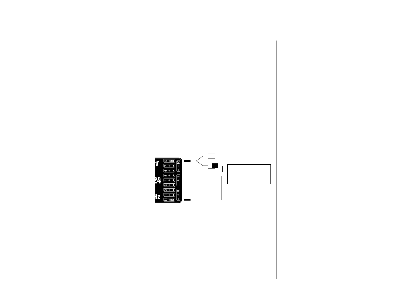
Receiver system power supply
Among other aspects, the safe operation of a model
depends on a reliable power supply. In the event that,
despite smooth operating rods, fully charged battery,
battery leads with adequate cross-section, minimum
contact resistances at connectors, etc., the transmitter
indicates repeated receiver voltage collapses or is
receiver voltage is generally too low; please give
attention to the following notices.
Give primary attention to fully charged batteries when
model operation is to be started. Be sure that the
contact surfaces of connectors and switches really are
low resistance. If necessary, measure the voltage drop
across installed switch cables when they are under
load because even new heavy-duty switches can cause
a voltage drop of up to 0.2 V. This value can increase
in contacts by factors as a consequence of aging and
oxidation. The constant vibrations and jarring also takes
its toll on contacts to produce a creeping increase of
contact resistance.
Servos present another possible problem source. Even
rather small servos like a Graupner/JR DS-281 can draw
up to 0.75 A of current when it is blocks under load. Just
four of these servos in a "foam" model can therefore load
down the on-board power supply by as much as 3 A …
Therefore you should choose a power supply which will
not break down under greater loads but rather always
deliver suffi cient voltage. To "calculate" necessary
battery capacity you should always fi gure on at least
350 mAh for every analog servo and at least 500 mAh
for every digital servo.
For example, from this point of view a battery with
1400 mAh would be the absolute minimum to power
a receiver system with a total of 4 analog servos. But
be sure to also consider the receiver itself into the
calculation because its bidirectional functionality will
draw about 70 mA of current too.
It is also a good practice to connect the receiver to
its power source with two cables rather than just one.
Cable "1" could be connected to the "12+B" receiver
connector as is usual and cable "2" could be connected
to the opposite end of the row at the connector labeled
"11+B". For example by using two power supply cables
to connect one switch or voltage regulator to the
receiver. Just use a V or Y cable, Order No. 3936.11
to accomplish this (see fi gure) if you should need one
or both of the receiver's connectors to attach a servo,
speed controller, etc. This double-connection technique
to switches and speed controllers not only reduces the
risk of a cable break but also ensures a more uniform
supply of power to the connected servo.
Aux. function
Y-lead
Order No. 3936.11
PRX stabilised
receiver power supply
Order No. 4136
NiMH 4-cell battery packs
In compliance with the aforementioned conditions, your
Graupner HoTT receiver system can be readily operated
with traditional 4-cell battery packs as long as the packs
have adequate capacity and voltage level.
NiMH 5-cell battery packs
Five-cell battery packs offer a greater voltage tolerance
than do 4-cell packs.
However, be aware that not every servo available on
the market is able to tolerate the voltage level output by
a 5-cell pack over the long term, this is particularly true
when the battery pack is freshly charged. Some of these
servos react to this with a noticeable "grinding" sound.
Therefore pay attention to the specifi cations of the
servos you use before making a choice for a 5-cell
battery pack..
LiFe 6.6 V batteries with 2 cells
From a contemporary perspective, these new cells are
the very best choice.
LiFe cells are also available in hard plastic casings to
protect them from mechanical damage. Like LiPo cells,
LiFe cells can be quick charged in suitable chargers and
they are comparatively robust.
This type of secondary cell battery is also rated for a
signifi cantly greater number of charge/discharge cycles
than, for example, LiPo batteries The nominal 6.6 V
output of a 2-cell LiFe battery pack does not present
a problem for either Graupner HoTT receivers nor for
those servos, speed controllers, gyros and other devices
which have been specifi cally approved for operation in
this – higher – voltage range. Please note however
that practically all servos, speed controllers, gyros
and other devices built in the past and most such
devices currently still offered on the market have
only a permissible voltage range of 4.8 to 6 V. Use
of these batteries in conjunction with these devices
demand use of a stabilized voltage regulator, e. g. the
PRX, Order No. 4136, see appendix. Otherwise there is
danger that attached devices will incur damage within a
short period of time.
LiPo 2-cell packs
For a given capacity, LiPo batteries are lighter than,
Installation notices
47
Page 48

for example, NiMH batteries. LiPo batteries are also
available in hard plastic casings to protect them from
mechanical damage.
The comparatively high nominal voltage, 7.4 V, for a
2-cell LiPo pack does not present a problem for either
Graupner HoTT receivers nor for those servos, speed
controllers, gyros and other devices which have been
specifi cally approved for operation in this – higher –
voltage range. Please note however that practically
all servos, speed controllers, gyros and other
devices built in the past and most such devices
currently still offered on the market have only a
permissible voltage range of 4.8 to 6 V. Use of these
batteries in conjunction with these devices demand use
of a stabilized voltage regulator, e. g. the PRX, Order
No. 4136, see appendix. Otherwise there is danger that
attached devices will incur damage within a short period
of time.
Installation notices
48
Page 49

Your notes
49
Page 50

Term defi nitions
Control function, control, function input, control channel, mixer, switch, control switch, fi xed switch
To make use of this mx-20 HoTT manual easier, a
number of the terms used repeatedly throughout this
manual have been defi ned below.
Control function
A "control function" is a signal intended to affect a
given control action – initially independent of its signal
course in the – . For example, this could be for throttle,
ruder or aileron in a winged aircraft or pitch, roll or
crow for a helicopter. A control function signal can
be applied directly over a single control channel or
also through a mixer and then applied over multiple
control channels. A typical example of multiple control
channels is separately operated aileron servos or the
use of two roll or crow servos in helicopters. The control
function explicitly includes the infl uence of the control's
mechanical travel on the respective servo.
Control
"Controls" include all operating elements on the
transmitter, which are directly activated by the pilot,
that impose an effect on servos, speed controllers etc.
connected to the receiver. This includes:
both joysticks (control functions 1 through 4), even •
though these four control functions can be freely
swapped around for both model types ("winged
aircraft" and "helicopters") by use of software "Mode"
settings, e. g. throttle left or right. The dual-axis
function for throttle/airbrake is often referred to as the
C1 control (channel 1).
the three • proportional rotary controls, which are
CTRL 6, 7 + 8,
the switches, SW 4/5 and 6/7, which are CTRL 9 and 10,•
switches SW 1 … 3 as well as 8 and 9, if assigned to •
a control channel via the "Transm. controls" menu.
Term defi nitions
50
The proportional operating elements produce a direct
effect on servos which is commensurate with the
control's position whereas switch modules can only
effect a two or three increment change.
Function input
This is an imaginary point in the signal path and must
not be considered the same as the point on the circuit
board where the transmitter control is connected.
The choice of "controls arrangement" and settings
in the "Transm. controls" menu have their effect
"downstream" of this imaginary point of connection.
Thus differences between the physical control's number
and the number of the downstream control channel can
indeed emerge.
Control channel
From the point at which a signal contains all control
information necessary for a particular servo – whether
directly from the physical control or indirectly by way of a
mixer – the term "control channel" is used. This signal is
only yet to be infl uenced by settings made in the "Servo
adjustment" menu and the "Transmitter output" menu
before it leaves the transmitter's RF module.
Once it arrives at the receiver, this signal may still
be modifi ed by settings made in the telemetry menu
before fi nally being applied as a control quantity for the
respective servo.
Mixers
The transmitter's software contains diverse mixer
functions. These can be used to apply one control
function to multiple servos or, conversely, to apply
multiple control functions to a single servo. Please look
over the numerous mixer functions in the text beginning
on page 145 of this manual.
Switches
The three standard 2-position switches, SW 2, 3 and
8, the two 3-position switches, SW 4/5 and 6/7, as well
as both pushbutton switches, SW 1 and 9, can also be
combined with control programming. However, these
switches are generally intended for switching program
options, e. g. to start and stop timers, to switch mixers
on and off, or as a teacher/pupil switchover, etc. Each
of these switches can be assigned any number of
functions.
Appropriate examples are detailed in the manual.
Control switches
Since it is very practical to have some functions
automatically switched on or off for a certain control's
position (e. g. switch on/off of a stopwatch for acquisition
of model run time, automatic extension of spoilers and
other possibilities), four control switches have been
integrated into mx-20 HoTT software.
These software switches, designated "G1 … G4", are
triggered by setting a switch-point along the physical
control's course of travel. This "trigger setting" is simply
defi ned with the press of a button. The switching
action can be correlated to the physical control's travel
direction by software.
Of course control switches can also be freely combined
with the aforementioned physical switches to solve even
more complex problems.
There is a series of instructive examples which make
this programming child's play. Learn about this by taking
advantage of the programming examples beginning on
page 226.
Page 51

Fixed switches FXI and FX
This type of switch turns a function permanently on,
e. b. timers (closed fi xed switch) or off (open fi xed
switch) or they can provide a fi xed input signal for a
control function, e. g. FXI = + 100 % and FX
For example, in fl ight phase programming, these fi xed
switches can be used to switch a servo or speed
controller between two settings.
= -100 %.
Term defi nitions
51
Page 52

Physical control, switch and control switch assignments
Principle procedure
The mx-20 Hott system exhibits maximum fl exibility
when it comes to assigning standard equipment
operating elements to specifi c functions.
Since the assignment of controls and switches is done
in the same way, even though different menus may be
involved, it is appropriate at this point to explain the
fundamental programming technique so that users can
concentrate on the particular contents when reading the
detailed menu descriptions.
Physical control and switch assignments
The "Control adjust" menu can be used to assign
transmitter inputs 5 … 12 to operate servos, both from
any given joystick direction (K1 … K4) as well as to
assign any other physical control designated "CTRL"
or switch designated "SW". After tapping on the center
SET key in the right key pad, the screen shown below
will appear.
Move desired switch
or control adj.
Now simply activate the desired control (joystick 1 … 4,
CTRL 6 … 10 or switch 1 … 3, 8 or 9).
Notice:
Rotary controls, CTRL 6 … 8, will not be recognized
until they "detent". Therefore these controls can be
turned back and forth until the correct assignment is
shown in the screen. If adjustment travel is insuffi cient,
activate the control in the other direction.
On the other hand, if you wish to assign a control in the
"Control switch" menu, page 119, the "activate desired
control" message will appear.
Physical control, switch and control switch assignments
52
push desired switch
into position ON
Important notice:
Controls to be assigned (particularly CON TROL 6 …
10) MUST be pre-assigned in the "Control adjust"
menu to one of the inputs 5 through 12!
Control assignment
Wherever programming permits a switch to be assigned,
a switch symbol will appear in the screen's bottom
display line.
Use the arrow keys in the left or right touch pad to select
the appropriate column.
How to assign a switch
Briefl y press the 1. SET-T key in the right touch pad.
The message shown below will appear in the screen.
Move desired switch
to ON position
(ext. switch: SET )
Now it is only necessary to put the selected switch 2.
into the desired "ON" position or, as described at the
right in "Assignment of external switches", to select
a switch from the list of "External switches". This
concludes the assignment. The switch symbol to the
right of the switch's number indicates the current
state of the particular switch.
Since CTRL 9 and 10 as well as the 3-position
switches, SW 4/5 and 6/7, are not only usable as
controls but also function as pure switches, there is a
total of 9 switches ("SW 1 … 9") available for use as
desired.
Changing switch action
If the activation of a switch is to result in the opposite
action, put the switch or joystick in the desired OFF
position, again activate the switch assignment and
reassign the switch again so it will respond with the
desired action.
Clear switch
A switch which has been assigned as described under
point 1 can be cleared by simultaneously pressing the
or key combination briefl y in the right key pad
(CLEAR).
Assignment from the "external switch" list
Those menus in which the message …
Move desired switch
to ON position
(ext. switch: SET )
… appears for switches designated with "SW" can be
used to assign so-called "external switches.
Do this by confi rming the message text with the SET
key. A new window will appear with a list of the four
control switches "C1 … C4", followed by two so-called
"FX" fi xed switches and the four inverted switches "C1i...
C4i".
Page 53

Control/fix sw
C1 C2 C3 C4 FX
FXi C1i C2i C3i C4i
Use the arrow keys in the left or right key pad to select
the desired switch then assign it with a brief tap on the
center SET key of the right touch pad.
Notices:
The two FX switches turn a function on "FXI" or off •
"FX " permanently.
All other switches mentioned can have multiple •
assignments. Pay attention that you do not
UNINTENTIONALLY assign reciprocally confl icting
functions to a single switch. If necessary, note down
the given switch functions.
Application examples:
Shut-off of an on-board glow plug heater upon •
underrun or overrun of an idle threshold point
programmed for the C1 joystick. In this case the glow
plug heater switch is controlled by a transmitter mixer.
Automatic switch on/off of the timer to measure pure •
"fl ight time" for a helicopter by way of a control switch
on the throttle limiter.
Automatic switch off of the "AI • Rud" when brake
fl aps are extended, for example to adapt the roll of
a model to the ground when making a landing on a
slope without inducing a change of fl ight direction
due to infl uence on the rudder.
Extending landing fl aps with elevator trim adjustment •
during a landing as soon as the throttle stick is
moved beyond its switch point.
Switch on/off of the timer for measuring the operating •
time of electric motors.
The control switches, freely programmable in the
"Control switch" menu, can be incorporated into
switch programming, i. e. assigned to a function instead
of a "normal" switch. At those program locations
where switches can be assigned you always have the
opportunity to assign one of the control switches, C1...
C4, instead of a physical switch by selecting one of
these out of the list of "external switches".
Physical control, switch and control switch assignments
53
Page 54
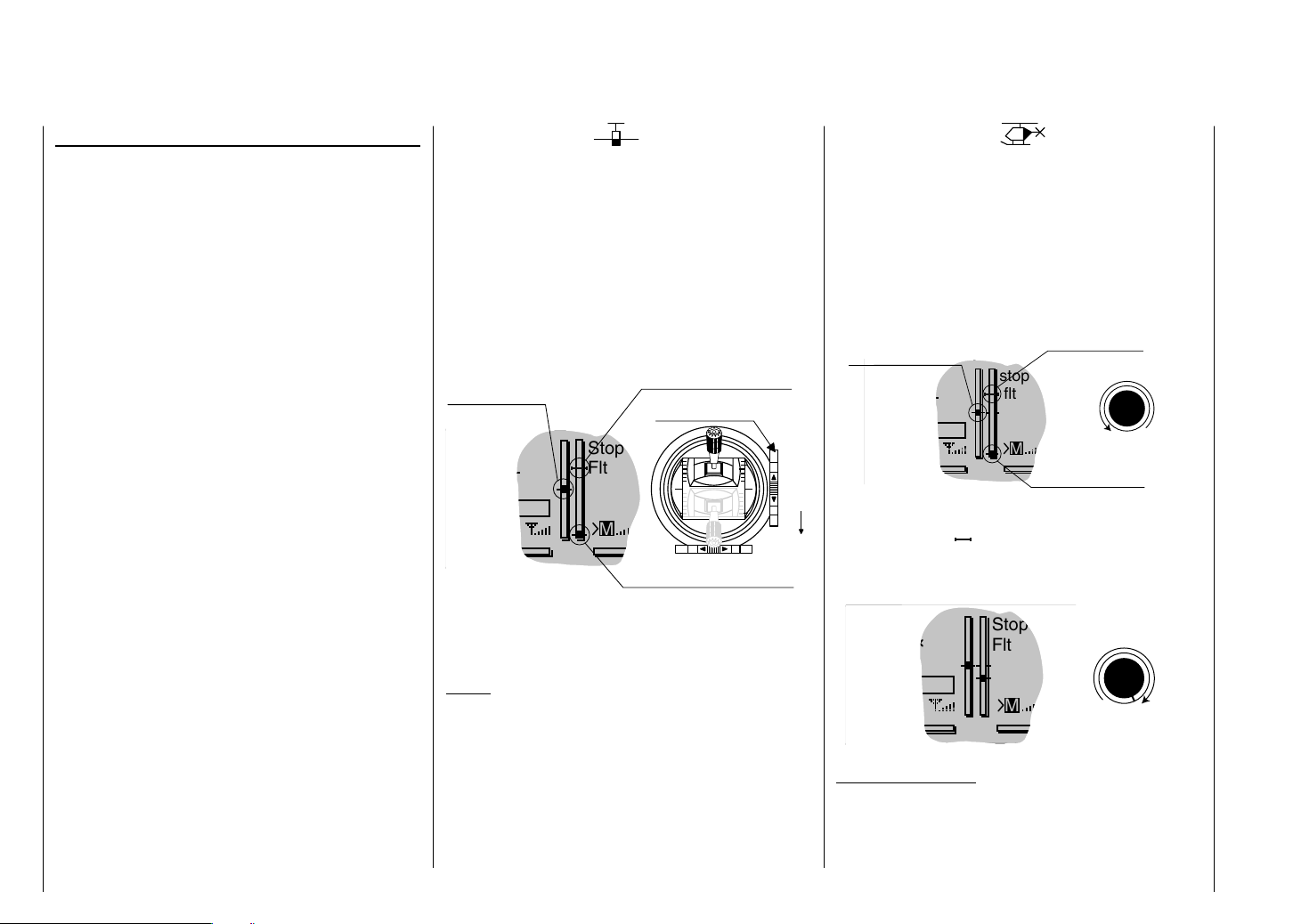
Digital trim
Functional description and description of C1 cut-off
Digital trim with visible and audible indicators
Both joysticks are equipped for digital trimming. When
you give the trim lever a brief push (one "click"), the
neutral position of the associated joystick channel
changes by one increment. If you hold the trim lever in
one direction, the trim value changes continuously in the
corresponding direction with increasing speed.
These changes can be made "audible" by way of different
frequency tones. This makes fi nding the mid-point during
fl ight easy, without looking at the screen. When the midpoint is overrun, a brief pause will be inserted.
Current trim values are automatically stored when a
model memory change is made. Furthermore, digital trim
exercises fl ight phase specifi c control within a memory
location (except for throttle/brake fl aps trim) – the socalled "C1" (channel 1) control function –.
This C1 trim includes yet another special function
for winged aircraft and helicopter models, it allows
the carburetor's idle setting to easily be found for a
combustion motor.
Since the trim functions described in these instructions
are only effective in the direction "Motor off", the
presentation in the screen of your transmitter may only
change with respect to individual throttle or Pitch-min
positioning of the C1 joystick in the "forward" or "back"
direction, such as throttle/pitch "left stick" or "right stick".
The illustrations in these instructions are always based
on "Throttle/Pitch right" for both types of models and
"Throttle back" for winged aircraft and helicopters.
Digital trim
54
1. Winged models
C1 trimming has a special cut-off trim function intended
especially for combustion motors. This cut-off trim
function is confi gured as follows. First put the motor into
a safe idle speed.
Now if you push C1 trim in a single motion toward its
"Motor cut-off" direction until it is in its furthest travel
position then an additional end-position marker will
remain in the display. When the motor is restarted you
can again immediately set the last idle speed with a
single movement in the direction of "more gas".
Current
trim position
GRAUBELE
#01
5.2V
3:33h
Stop
Flt
K78
M
Current trim position
Ch 1 trim lever
0:00
0:00
2.4
RX0.0V
Trim at motor OFF position
This cut-off trim will be deactivated when "None" is
entered on the "Motor at C1" line of the "Model Type"
menu, see page 82.
Notice:
Since this trim function is only effective in the "Motor
off" direction, the display illustrated above will change
appropriately if the C1 joystick's control direction for
minimum throttle is changed from "back" to "front" (on
which the above illustration is based) in the "Motor at
C1" line of the "Basic Settings" menu.
2. Helicopter models
In addition to the "Cut-off trim" function described
below in "Winged aircraft models", C1 trimming also
has another characteristic which is made possible by
combining it with a so-called "Throttle limit" function see
page 104. As long as the throttle limit control remains in
the "left" half of its travel path, i. e. in the startup range,
C1 trimming acts on the throttle servo as idle trim and the
indication for idle trim is visible in the screen's display.
Current trim position
GRAUBELE
#01
5.2V
3:33h
Idle direction
Last idle position
stop
flt
K78
RX0.0V
M
Trim at
motor OFF position
Throttle limit control
0:00
0:00
2.4
CTRL 6
However, in contrast to winged aircraft models, the
position indicator ( ) will be hidden and any preset idle
position will be deleted when the throttle limit control is
in the "right" half of its travel path.
GRAUBELE
#01
5.2V
3:33h
Stop
Flt
K78
M
0:00
Throttle limit control
0:00
RX0.0V
2.4
CTRL 6
Notice for helicopters:
C1 trimming affects only the throttle servo, not the pitch
servo. Notice also that the helicopter throttle servo must
be connected to receiver output 6, see receiver layout
on page 59.
Page 55

Your notes
55
Page 56

Winged models
Convenient support is provided for up to four aileron
servos and four fl ap servos on normal models or, for
V tail and fl ying wing/delta models, up to two aileron/
elevator servos plus four fl ap servos.
The majority of motorized and glider models belong to
the tail unit type "normal" and are equipped with one
servo each for elevator, rudder and ailerons in addition
to a motor throttle or electronic speed controller (or for
brake fl aps in the case of a glider model). Beyond this,
tail unit type "2HRSv3+8" permits the connection of two
elevator servos to receiver outputs 3 and 8.
If ailerons, and conditionally the fl aps, are each actuated
with two separate servos then settings can be made for
differentiated control of all aileron and fl ap pairs in the
"Wing mixers" menu, i.e. settings for downward ruder
throw independent of upward throw.
Finally, the position of fl aps can be controlled by a
control out of group CTRL 6 … 10. Alternatively, there
is a phase-dependent trim function available for fl aps,
ailerons and elevators in the "Phase trim" menu.
The "V tail unit" is to be selected from the "Model
type" menu if the model has a V tail unit instead of
a normal tail unit. This V tail unit selection provides
coupled elevator and ruder control functions for both
tail fl aps – each controlled by a separate servo – which
handles both elevator and ruder functionality.
For delta and fl ying wing aircraft models, aileron and
elevator functionality is affected by way of a common
rudder fl ap on the trailing edge of each side (right and
left) of the wing. The program contains appropriate mixer
functions for both servos.
Up to 7 fl ight phases can be programmed into each of
the 24 model memory locations.
Except for C1 trim, digital trim will be stored on a
fl ight-phase basis. C1 trim permits easy location of a
carburetor idle setting.
Two timers are always available for fl ight operation. The
transmitter operating time expired since the last battery
charge is also displayed.
All transmitter controls (CTRL) and switches (SW) can
be assigned in the "Control adjust" menu to inputs 5
… 12 with almost no restrictions.
The "Dual Rate" and "Exponential" functions for ailerons,
rudder and elevators are separately programmable and
each are convertible between the two variations on a
specifi c fl ight-phase basis.
In addition to 8 freely allocatable linear mixers, 4
curve mixers ("Free mixers" menu) and 4 dual mixers
("Dual mixer" menu), there are also fl ight-phase
dependent 6-point curves for control channel 1 (throttle/
brake), see "Channel 1 curve" menu).
Depending on the number of wing servos, fi xeddefi nition mix and coupling functions can be selected
from a list in the "Wing mixers" menu.
Multi-fl ap menu: control of fl aps as ailerons, the •
infl uence aileron trim on fl aps controlled as ailerons,
fl ap differentiation, fl ap function throw magnitude for
all aileron and fl ap pairs, ailerons controlled as fl aps,
elevator mixer fl aps
Brake settings: butterfl y, differential reduction, •
elevator curves
aileron • rudder mixer
fl aps • elevator mixer
i
A
r
o
t
a
v
e
l
E
l
E
Winged models
56
Airbrake-Function 1
AI
n
o
r
e
l
FL
p
a
l
F
r
o
t
a
v
e
FL
r
o
t
a
v
e
l
E
A
p
a
l
F
F
i
l
e
l
a
p
A
i
l
e
A
i
r
o
l
n
e
R
u
d
d
e
r
AI
r
o
n
p
F
a
l
r
o
n
r
e
d
d
u
R
n
o
r
e
l
i
A
t
o
r
a
v
e
l
E
F
l
a
p
r
o
p
t
a
a
l
v
F
e
l
E
F
l
a
n
p
o
r
e
l
i
A
left
right
Airbrake
Airbrake
Flap
Elevator
Rudder/Elevator
left
V-Tail
right
AI
AI2
A
I
FL
A
I
FL2
L
F
F
L
E
E
L
FL2
RU AI
FL
AI2
F
L
F
L
A
A
I
AI
I
L
F
L
F
L
EL AI
Brake AI, AI2
FL, FL2
Brake
Elevator
Brake
Page 57

Installation notices
t
Servos MUST be connected to the receiver in the
sequence illustrated here.
Outputs which are not needed are simply left empty.
Also be sure to follow the notices on the next pages.
Winged aircraft with and without motor, having up to
4 aileron servos and up to 4 fl ap servos …
… and tail plane type "normal" or "2 elevator
servos"
Free or right flap 2 or aux. function
Free or left flap 2 or aux. function
Free or 2nd elevator or aux. function
Free or right aileron 2 or aux. function
Receiver power supply
Right flap or free or aux. function
Flap or left flap
Right aileron or aux. function
Rudder
Elevator or 1st elevator
Aileron or left aileron
Airbrake or throttle servo
or speed controller (electric motor)
Receiver power supply
Free or left aileron 2 or aux. function
… and tail plane type "V tail unit"
Free or right flap 2 or aux. function
Free or left flap 2 or aux. function
Free or aux. function
Free or aux. function
Receiver power supply
Right flap or free or aux. function
Flap or left flap
Right aileron or aux. function
Right rudder / elevator
Left rudder / elevator
Aileron or left aileron
Airbrake or throttle servo
or speed controller (electric motor)
Receiver power supply
Free or aux. function
Delta/fl ying wing aircraft models with and without
motor having up to two aileron/elevator servos and
up to 2 fl ap/elevator servos
Free or aux. function or right flap 2 / eleva
Free or aux. function or left flap 2 / elevato
Free or aux. function
Free or aux. function
Receiver power supply
Free or right flap / elevator
Free or left flap / elevator
Free or aux. function
Free or rudder
Right elevon
Right elevon
Airbrake or throttle servo
or speed controller (electric motor)
Receiver power supply
Free or aux. function
Because of orientation differences for installed servos
and their rudder linkages, the actuating direction of
some servos may be initially backward. The table below
provides remedies.
Model
type
V tail Rudder and
Delta,
fl ying
wing
Servo actuation
direction
wrong
elevator reversed
Rudder correct,
elevators reversed
Elevators correct,
rudder reversed
Elevator and
aileron reversed
Elevator correct,
aileron reversed
Aileron correct,
elevators reversed
Remedy
Reverse the polarity of
servos 3 & 4 in the "Servo
adjustment" menu
Swap the connections
for servos 3 & 4 on the
receiver
Reverse the polarity of
servos 3 & 4 in the "Servo
adjustment" menu AND
on the receiver
Reverse the polarity of
servos 2 & 3 in the "Servo
adjustment" menu
Reverse the polarity of
servos 2 & 3 in the "Servo
adjustment" menu AND
on the receiver
Swap servos 2 & 3 at the
receiver
All "program descriptions" for menus relevant to a
winged aircraft model are marked with a winged aircraft
symbol …
… so only these menus need to be dealt with to program
a winged aircraft model.
Winged models
57
Page 58

Helicopter models
The advanced developments incorporated into the
transmitter as well as those now in helicopter models
and their components like gyros, speed regulators, rotor
blades, etc. make it possible to master a helicopter even
in 3D acrobatic fl ight. On the other hand, a beginner
needs only a few settings to get started with hovered
fl ight training and then can take advantage of mx-20
HoTT features, step-by-step, with increasing expertise.
The mx-20 HoTT program can operate all
conventional helicopters having 1 … 4 servos for pitch
control.
Six fl ight phases plus autorotation are available within
a model memory, see menus "Control adjust", "Phase
settings" and "Phase assignment".
As with winged aircraft, here too, in addition to the basic
screen's standard timers there are additional timers
as well as a lap counter with fl ight-phase-dependent
stopwatch functionality which are available for selection
(menus "Timers (general)" and "Fl. phase timers").
Except for pitch/throttle trimming, digital trimming can be
stored as "global" for all fl ight phases or as "fl ight phase
specifi c". C1 trim permits easy location of an idle setting.
The control assignments of inputs 5... 12 can be made
common to every fl ight phase or separate ("Control
adjust" menu).
A fl ight phase copy function is helpful during fl ight trials
("Copy / Erase" menu).
"Dual Rate" and "Exponential" functions can be coupled
for roll, nick and tail rotor and programmable in two
variations in every fl ight phase.
There are 8 freely assignable linear mixers. There are
also 4 curve mixers that can be programed and these
can also be switched on or off, depending on the fl ight
phase, in the "Mix active/Phase" menu. Beyond this,
Helicopter models
58
there are also 4 dual mixers available.
Available in the "Helicopter mixer" menu are fl ight-
phase-dependent 6-point curves for pitch, throttle and
tail rotor mixer non-linear characteristics as well as two
independent swashplate mixers each for roll and nick.
Independent of this, the control curve of the channel
1 joystick can be defi ned with up to 6 points in every
fl ight phase. The beginner will initially only adapt the
hover fl ight point to the control middle for the non-linear
characteristics.
Pre-programmed mixers in the "Helicopter mixer"
menu:
Pitch curve (6-point curve)1.
Channel 1 2. Throttle (6-point curve)
Channel 1 3. Tail rotor (6-point curve)
Tail rotor 4. Throttle
Roll 5. Throttle
Roll 6. Tail rotor
Collective
Pitch Curve
Swashplate
Rotation
Roll
Throttle
Pitch-Axis
Channel 1
Throttle
Throttle
Nick 7. Throttle
Nick 8. Tail rotor
Gyro suppress9.
Swash rotation10.
Swash limiter11.
The "Throttle limit" function (input 12 in the "Control
adjust" menu) allows the motor to be started in any
fl ight phase. Control 6 – the proportional rotation control,
CTRL 6 top left – is assigned to input 12 by default. This
"throttle limiter" establishes – depending on its given
position – the maximum possible carburetor position.
This makes it possible for the motor to be controlled in
the idle range, if necessary even by the proportional
regulator. The throttle curves become effective only
when the proportional regulator is pushed toward the full
throttle direction.
l
i
a
R
o
T
t
o
1
l
e
n
n
a
h
C
T
a
i
l
R
r
Roll
o
t
o
r
e
T
l
r
t
h
t
o
Tail Rotor
Pitch-Axis
Channel 1
Tail Rotor
Tail Rotor
Page 59

Notice for those transitioning from older Graupner
systems:
In comparison to previous receiver layouts, servo
connector 1 (pitch servo) and servo connector 6
(throttle servo) have exchanged places. Servos must
be connected to receiver outputs as illustrated at the
right in the bottom fi gure. Outputs which are not used
are simply left empty. More details about respective
swashplate types can be found on page 86 in the
"Basic settings" menu.
Installation notices
Servos MUST be connected to the receiver in the
sequence illustrated here.
Outputs which are not used are simply left empty.
Also be sure to follow the notices on the next pages.
Notice:
A speed regulator is also to be connected to receiver
output "6" in order to take full advantage of the throttle
limiter's convenience and safety features, see text
beginning on page 104. See page 169 about this.
Receiver layout for helicopter models …
… with 1 to 3 swashplate servos
Free or aux. function
Free or aux. function
Free or speed governor or aux. function
Free or aux. function
Receiver power supply
Gyro gain
Throttle servo or speed controller
Free or aux. function
Tail rotor servo (gyro system)
Pitch-axis 1 servo
Roll 1 servo
Collective pitch or roll 2 or
Pitch-axis 2 servo
Receiver power supply
Free or aux. function
… with 4 swashplate servos
Free or aux. function
Free or aux. function
Free or speed governor or aux. function
Free or aux. function
Receiver power supply
Gyro gain
Throttle servo or speed controller
Pitch-axis 2 servo
Tail rotor servo (gyro system)
Pitch-axis 1 servo
Roll 1 servo
Roll 2 servo
All menus relevant to helicopter models are marked
in the "program descriptions" section with a helicopter
symbol …
… so only these menus need to be dealt with to program
a helicopter model.
Receiver power supply
Free or aux. function
Helicopter models
59
Page 60

Detail program description
Loading a new memory location
Anyone who has worked through to this part of
the manual has certainly already tried out a bit of
programming. Nevertheless a detailed description of
every menu should not be left out.
This section begins with the loading of a "free" memory
location, a procedure which would be performed if a new
model was being "programmed".
GRAUBELE
#01
5.9V
0:00h
Stop
Flt
K78
M
0:00
0:00
HoTT
0.0V
From the base screen, a jump to the "Multi-function list"
is made by tapping on the center SET button of the right
touch pad. (The center ESC button of the left touch pad
will cause a jump back to the base screen.) By default,
when the multi-function list is called for the fi rst time
after switching on the transmitter, the "Model select"
menu item will be active and displayed in reverse video.
If this is not the case, use the arrow keys (, ) of
the left or right touch pad to select the "Model select"
menu item …
Model select
Copy / Erase
Suppress menus
Suppress models
Base setup model
Model type
… then (again) tap the center SET button of the right
key pad.
Detail program description - Loading a new memory location
60
01
02
03
04
05
06
free
free
free
free
free
R12
In the transmitter's delivered state, the fi rst model
memory is initialized to the "winged aircraft" model
type and the receiver in the delivery is bound to this
model memory location, recognizable by the displayed
receiver code at the right end of the line. In the above
example, R12 is a code for the GR-24 receiver included
in the set. In contrast, a "non-bound" model memory
would appear with the code placeholder "---".
The remaining memory locations, marked
"
free", are not occupied and thus also
"non-bound". If you wish to program a winged aircraft
model then, after leaving the "Model select" menu by
tapping on the center ESC button of the left touch pad,
programming of the model can begin right away … or
now use the or keys of the left or right touch pad
to select one of the free memory locations …
01
02
03
04
05
06
free
free
free
free
free
R12
… and then tap on the center SET key of the right touch
pad to confi rm the choice.
Afterward you will be prompted to select the basic model
type, i.e. either "winged model" or "helicopter model".
Select model type
Use the or of the left or right key pad to select
the basic model type then tap the center SET button
in the right key pad. This initializes the selected model
memory with the selected model type and the display
will return to the base screen. The memory location is
now accordingly occupied.
On the other hand, if you wish to begin with a helicopter
then use the or keys of the left or right key pad to
select a memory location labeled "free" and
tap briefl y on the center SET button in the right key pad
to confi rm your choice. You will be now be prompted to
select the basic model type, i.e. either "winged model" or
"helicopter model". Select the appropriate symbol with
the or keys of the left or right touch pad then tap
briefl y on the center SET button in the right touch pad to
confi rm your choice. This initializes the selected model
memory with the selected model type and you can now
program your model into this model memory.
Changing over to another model type is still possible if
you fi rst erase this memory location ("Copy / Erase"
menu, page 64).
Notice:
If, from the base screen, the currently active model •
memory is to be erased then immediately after the
erase action one of the two model types, "Winged"
or "Heli" must be defi ned. You cannot avoid this
selection even if you switch the transmitter off. When
Page 61
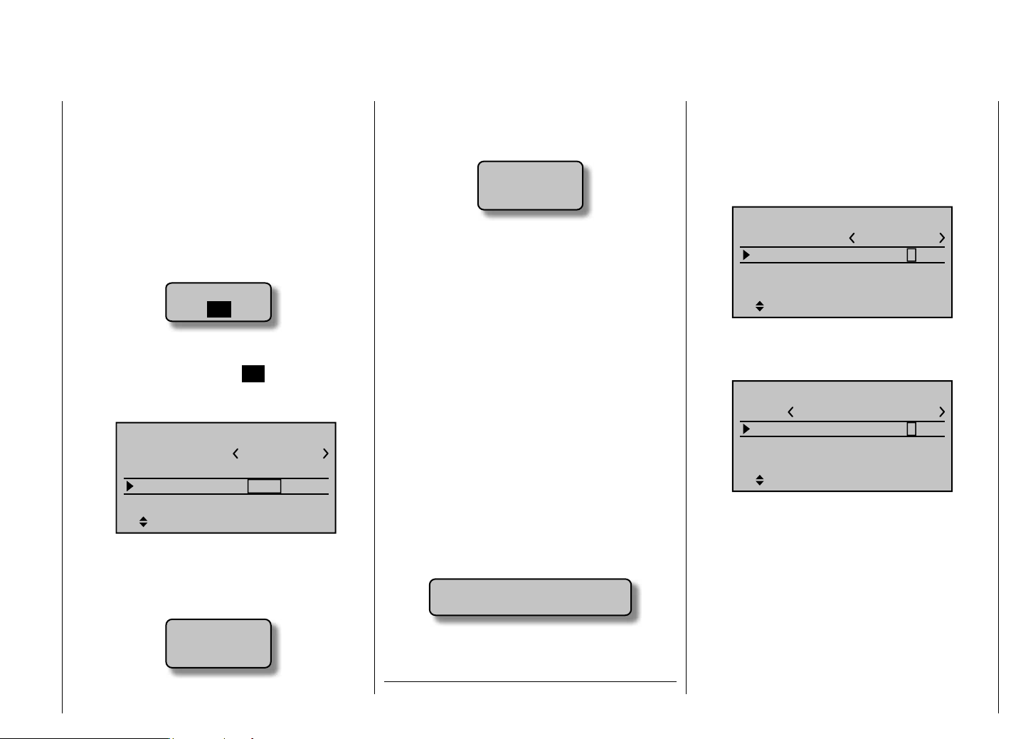
the transmitter is switched on again the undesired
occupation of the that model memory will have to be
erased from another memory location.
In contrast, if a non-active memory location is erased,
it will subsequently be marked as "
free" in
the "Model select" menu.
After the selected model memory is initialized with •
the desired model type, the display will switch to the
base screen of the freshly occupied model memory.
At this time the warning …
BIND N/A
OK
… will appear in the screen for a few seconds as
notifi cation that a "bond" to a receiver does not exist.
With a brief tap on the center SET button in the right
touch pad you can jump directly to the appropriate
option.
BASIC SETTINGS, MODEL
Mod.name
Stick mode
RF BIND
n/a
1
n/a
RF transmit OFF
BD1
BD2
Further details about binding a receiver can be found
on page 69 or 75.
After the aforementioned "BIND. N/A" warning •
message closes automatically, the warning …
Fail Safe
setup
t.b.d.
… will appear (also for just a few seconds) to serve
notice that no failsafe settings have yet been made.
More about this can be found on page 192.
If the screen should display the warning …•
as well as rolling, pitching, tail rotor and throttle/pitch
for helicopter models, to the two joysticks. Just which
of these methods is used depends on the preferences
of the individual model pilot. This function is set for the
Throttle
too
high !
… then move the throttle joystick, or the limiter for
a helicopter, into its idle position; by default this is
rotary control CTRL 6.
The appearance of this warning also depends on
the "Motor at C1" or "Pitch min" in the "Model type"
currently active model memory in the "Stick mode" line
of the "Basic settings, model" menu, page 68 or 74.
BASIC SETTINGS, MODEL
Mod.name
Stick mode
RF BIND
Rcv Ch Map n/a
menu, refer to page 80 or "Helicopter type" page 84
for the selected setting. For winged aircraft models,
select "None" to deactivate this message if you have
no motor to enter.
If the transmitter already has occupied model •
memories then submenus of the "Copy / Erase"
menu will display a pictogram of the selected model
type at the respective memory location followed by a
blank line or the model name which was entered in
A default value for this setting can be made for future
models in the generalized "Basic Settings" menu, page
216.
BASIC SETTINGS
Own
Stick mode
DSC Output
Pitch min
the "Basic settings " menu (see page 68 or 74) and
any bond that may exist between a receiver and this
model memory.
If battery voltage is too low, you cannot• switch
models for safety reasons. A corresponding message
will appear in the display:
not possible now
voltage too low
As a basic principle, there are four different ways to
assign the four control functions, aileron, elevator,
rudder and throttle or brake fl aps for winged models
* N.N. = Nomen Nominandum (the name to be stated)
It should be noted here once again that, in the interest
of greatest fl exibility in combination with the prevention
of unintentional operating errors, no controls are
preassigned to control channels 5 … 12 by default.
This means that, in the system's delivered state, only
servos attached to receiver outputs 1 … 4 can be
moved by the two joysticks and that any servos
attached to receiver connectors 5 … 12 (max)
will remain in their middle positions. When a new
helicopter model is initialized, servo 6 may perform a
movement – depending on the throttle limiter's position,
Detail program description - Loading a new memory location
bind
R12
1
n/a
SEL
1
PPM10
back
SEL
61
Page 62

CTRL 6 – . This condition changes for both model types
only after the respective assignments have been made
in the "Control adjust" menu.
On the other hand, if a newly initialized model memory
is to be put into operation then it MUST fi rst be
appropriately "connected" with one or more receivers
before the servos attached to the receiver/s can be
operated. More about this can be found in the section
"Binding" on page 69 or 75.
A fundamental description of programming steps for a
winged aircraft model can be found in the programming
examples section beginning on 226, or for helicopter
models beginning on page 270.
The menu descriptions below are arranged in the
sequence individual menus are listed in the multifunction list.
Detail program description - Loading a new memory location
62
Page 63

Model select
Call up model 1 … 24
The basic operation of the transmitters keys was
explained on pages 24 and 25 and, on the previous
double-page, explanations were provided for navigating
to the multifunction list and about how to occupy a new
model memory. At this point we now wish to begin with
the "normal" description of individual menu items in the
sequence they are arranged in the transmitter. Therefore
we will begin with the menu …
Model select
Model select
Copy / Erase
Suppress menus
Suppress models
Base setup model
Model type
As many as 24 complete model settings, including
digital trim values for trim levers, can be stored.
Trimming is stored automatically such that a switchover
from one model to another does not cause a loss of
current trim settings. To the right of the model number,
each occupied model memory line in this display shows
a pictograph of the model type as well as the model's
name entered for the model in its "Basic settings,
model" menu, page 68 or 74 and the code, if present,
for the receiver "bound" to the model memory location.
Select the "Model select" menu with the arrow keys of
the left or right touch pad then press briefl y on the SET
button in the right touch pad.
01
02
03
04
05
06
Now use the arrow keys of the left or right touch
pad to select the desired model memory from the list
and activate the selection by pressing the SET button.
Pressing the ESC button will cause a return to the
previous menu page without activating a model change.
Notice:
If a model change causes a "Throttle too high" •
warning to appear, the throttle/pitch joystick (C1) or
the throttle limiter is too far in the full throttle direction.
If a model change causes the message …•
… to appear then binding settings should be checked.
If a model change causes the message …•
… to appear then respective failsafe settings should
be checked.
If battery voltage is too low, the model switchover •
cannot be made due to reasons of safety. An
appropriate message will appear in the screen.
GRAUBELE
ULTIMATE
STARLET
BELL47G
free
free
OK
BIND N/A
Fail Safe
setup
t.b.d.
R12
R12
R12
–––
not possible now
voltage too low
Detail program description - Model select
63
Page 64

Copy / Erase
Erase or copy model model, copy from or to SD card, copy fl ight phases
Select the "Copy / Erase" menu with thearrow
keys of the left or right touch pad then briefl y press the
SET button.
Model select
Copy / Erase
Suppress menus
Suppress models
Base setup model
Model type
Erase model
Model select
Copy / Erase
Suppress models
Base setup model
Model type
Suppress: TOG
Select the "Erase model" sub-menu with the arrow
keys of the left or right touch pad then briefl y press the
SET button.
Use the arrow keys of the left or right touch pad to
select the model to be erased …
Model select
Copy / Erase
Suppress models
Base setup model
Model type
Suppress: TOG
… now the next time the SET button is pressed, it will
prompt the confi rmation request …
BASIC SETTINGS, MODEL
Mod.name
Stick mode
RF BIND
STARLET
n/a
1
n/a
RF transmit OFF
SEL
… to appear. A NO response will cause the process to be
canceled and a return to the previous screen. Selecting
the YES response with the
arrow keys of the left or
right touch pad followed by confi rmation of the selection
by briefl y pressing the SET button will erase the selected
model memory.
Attention:
This erase process cannot be undone. All data in the
selected model memory will be erased completely.
Notice:
If the currently active model memory is to be erased,
a model type "Winged" or "Heli" must be defi ned
immediately after the erase process. On the other hand,
if an inactive memory location is to be erased then it
will subsequently appear in the model select screen as
"free".
Copy model model
Select the "Copy model model" sub-menu with the
arrow keys of the left or right touch pad then press
SET button.
the
0s
0s
0s
SEL
–––
–––
–––
–––
–––
Timer1
Timer2
Timer3
0:00
0:00
0:00
Lap time/tim tab
Lap Display
SEL
Select the model to be copied with the arrow keys
of the left or right touch pad …
TELEMETRY
TEL.RCV
SETTING & DATA VIEW
SENSOR SELECT
RF STATUS VIEW
VOICE TRIGGER
BIND. 1
… whereby a second activation of the SET button in the
right touch pad will allow the "Copy to model" window
for the destination memory to be selected with the
arrow keys of the left or right touch pad and then
confi rmed with yet another press of the SET button or
canceled with the ESC button. A memory location which
is already occupied can be overwritten.
BASIC SETTINGS, MODEL
Mod.name
Stick mode
RF BIND
Rcv Ch Map n/a
GRAUBELE
1
bind
n/a
R12
BD1
BD2
Detail program description - Copy / Erase
64
Page 65

Once selection of the model memory has been
confi rmed by pressing the SET button, a confi rmation
request will appear.
modell really
01
03
ULTIMATE
frei
to be copied?
NO
YES
A NO response will cancel the process and return the
screen to the originating screen. If the YES response
is selected and confi rmed by activating the SET button
then the selected source model will be copied into the
selected model memory destination.
Notice:
In addition to model data, binding data is also copied by
this process. This means that a receiver system which
was/is bound to the original model memory can also be
operated by its copy without establishing the bond again.
Export to SD
Select the "Export to SD" sub-menu with the arrow
keys of the left or right touch pad and press the
SET
button.
Erase model
Copy model–>model
Export to SD
Import from SD
Copy flight phase
=>
=>
=>
=>
=>
=>
=>
Select the model to be exported with the arrow
keys of the left or right touch pad.
export to SD-CARD:
01
02
03
04
05
GRAUBELE
ULTIMATE
STARLET
BELL47G
frei
R12
R12
R12
–––
After confi rming the selected model memory by pressing
the SET button, a confi rmation request will appear.
modell
01
ULTIMATE
SD-Karte
export ?
NO
YES
A NO response will cancel the process and return the
screen to the originating screen. However, if the YES
response is selected then confi rmed by pressing the SET
button, the selected model will be copied to the SD card.
Notice:
Should the notice …•
SD-CARD
INSERT
OK
… appear instead of a screen for model selection,
there is no SD card in the transmitter's card slot, see
page 22.
In addition to model data, binding data is also copied •
by this process. This means that a receiver system
which was/is bound to the original model memory
can also be operated in the SAME transmitter by its
copy without establishing the bond again.
An exported winged aircraft model will be stored •
on the memory card in the \\Models\mx-20 folder
with a fi lename format of "aModellname.mdl"
and a helicopter model with a fi lename format
of "hModellname.mdl". On the other hand, if a
"nameless" model is exported, its data will be stored
on the memory card under "ahNoName.mdl" or
"hNoName.mdl", as appropriate.
Some special characters that can be used in model •
names are subject to specifi c restrictions associated
with the FAT or FAT32 fi le system used by the
memory cards and these special characters will be
replaced during the copy process with a tilde (~).
A model fi le already on the memory having the same •
name as the fi le to be copied will be overwritten
without warning.
Detail program description - Copy / Erase
65
Page 66

Import from SD
Select the "Import from SD" sub-menu with the
arrow keys of the left or right touch pad and press
the SET button.
Erase model
Copy model–>model
Export to SD
Import from SD
Copy flight phase
=>
=>
=>
=>
=>
=>
=>
Select the model to be imported from the SD memory
card with the arrow keys of the left or right touch
pad.
import from SD-CARD:
ALPINA
EXTRA
COBRA
BELL47G
05
frei
11/03/10
11/03/11
11/03/11
11/03/12
Notice:
The export date posted at the right end of each model
name line is represented in the format "year/month/day".
After again pressing the SET button in the right touch
pad, the "import to model" window will appear Now
the destination memory location can be selected with
the arrow keys of the left or right touch pad and
confi rmed by pressing the SET button or the process
can be canceled with the ESC button. A memory
location which is already occupied can be overwritten.
Detail program description - Copy / Erase
66
import to model:
01
02
03
04
05
GRAUBELE
ULTIMATE
STARLET
BELL47G
free
R12
R12
R12
–––
After confi rming the selected model memory by pressing
the SET button, a confi rmation request will appear.
modell
01
03
ULTIMATE
free
import ?
NO
YES
A NO response will cancel the process and return the
screen to the originating screen. However, if the YES
response is selected and confi rmed by pressing the SET
button then the selected source model will be imported
into the selected destination model memory.
Notice:
If the message …•
SD-CARD
INSERT
OK
… appears instead of a screen for model selection,
there is no SD card in the transmitter's card slot, see
page 22.
In addition to model data, binding data is also •
imported by this process. This means that a receiver
system which was/is bound to the original model
memory can also be operated in the SAME transmitter
by its copy without establishing the bond again.
Copy from phase
Select the "Copy from phase" sub-menu with the
arrow keys of the left or right touch pad then press the
SET button.
Erase model
Copy model–>model
Export to SD
Import from SD
Copy flight phase
=>
=>
=>
=>
=>
=>
=>
In the "Copy from phase" sub-menu …
Copy from phase:
1
3
5
7
2
4
6
=>
=>
… the fl ight phase to be copied (1 … 7 for winged
aircraft models or 1 … 6 for helicopter models) is
selected with the arrow keys of the left or right touch pad
then confi rmed by briefl y pressing the SET button in the
right touch pad. The next window to appear will be the
"Copy to phase" window. In that window the destination
is to be selected and then also confi rmed. As described
above, another confi rmation request will be issued.
Page 67
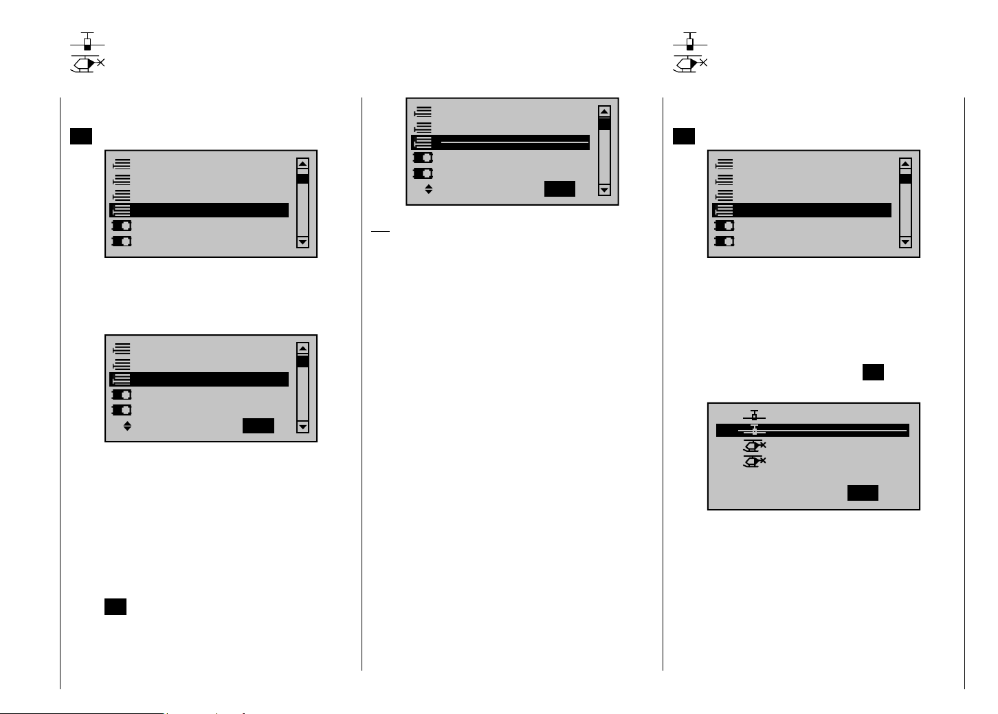
Suppress menus
Suppress models
Hide menus in the multifunction
Select the "Suppress menus" menu with the arrow
keys of the left or right touch pad then briefl y press the
SET button.
Model select
Copy / Erase
Suppress menus
Suppress models
Base setup model
Model type
In the menu which then appears, menu items which
are no longer needed or those which should not
be changed, can be blocked from appearing in th
multifunction list.
Model select
Copy / Erase
Suppress models
Base setup model
Model type
Suppress: TOG
This reduces the appearance of the multi-function list
considerably, in some cases to only a few menus,
thus substantially improving the clarity of the function
selection list. Functions are not deactivated because
they are hidden. They will simply no longer appear in the
list. This also blocks direct access to these functions.
The function to be hidden or displayed is to be selected
with the arrow keys of the left or right touch pad then
its (hide/display) status switched-over by means of the
center SET button in the right touch pad.
Model select
Copy / Erase
Suppress models
Base setup model
Model type
Suppress: TOG
Tip:
If you wish to forgo access-blockage to the multifunction list altogether, hide the "Code lock" menu
in the multi-function list by way of this menu as a
precautionary measure.
Hiding model memory locations
Select the "Suppress models" menu with the arrow
keys of the left or right touch pad then briefl y press the
SET button.
Model select
Copy / Erase
Suppress menus
Suppress models
Base setup model
Model type
Model memories which are rarely needed or to which
access is to be blocked for other reasons can be hidden
from the model selection list. This also clarifi es the
overview layout for model selection.
A model to be hidden/displayed is selected with the
arrow keys of the left or right touch pad then its status is
switched-over by means of the center SET button in the
right touch pad.
01
02
03
04
05
A model memory which is "stricken through" will no
longer appear in the "Model select" menu.
GRAUBELE
ULTIMATE
STARLET
BELL47G
free
Suppress:
E12
E12
E12
–––
TOG
Detail program description - Suppress menus and models
67
Page 68

Base setup model
Model-specifi c base settings for winged aircraft models
Before programming specifi c parameters, there are
some basic settings to be made which effect the
currently active model memory.
Select the "Base setup model" menu with the arrow
keys of the left or right touch pad then press the center
SET button in the right touch pad.
Suppress models
Base setup model
Model type
Servo adjustment
Stick mode
Control adjust
Model name
BASIC SETTINGS, MODEL
Mod.name
Stick mode
RF BIND
n/a
RF transmit OFF
BD1
Change to the next screen page by pressing the SET
button briefl y. This will open a screen of characters for
entry of the model's name. A maximum of 9 characters
can be used to specify a model name.
!"#$%&’()+,–./012
3456789:;
?@AB CDE
FGHIJKLMNOPQRSTUVWX
YZ[¥]^_`abcdefghijk
Mod Name
Detail program description - Base setup model
68
GRAUB
1
n/a
BD2
Select the desired characters with the arrow keys of the
left touch pad. Move to select the next character position
by pressing the arrow key of the right touch pad or its
SET button. Simultaneously pressing the or
center
of the right touch pad (CLEAR) will place a space
character at the position.
Positioning to any character position within the entry
fi eld can be done with the keys of the right touch
pad.
A return to the previous menu screen is accomplished
by pressing the center ESC button in the left touch pad.
After entering the model name it will appear in the base
screen of the "Model select" menu and in the sub-menu
for the "Copy /Erase" menu item.
Stick mode
"MODE 1" (throttle left)
Stick forward
Rudder left
Stick back
"MODE 3" (throttle right)
Stick forward
Aileron left
Stick back
Rudder right
Aileron right
Motor full throttle
Aileron left
Motor idle
Motor full throttle
Rudder left
Motor idle
"MODE 2" (throttle left)
Motor full throttle
Aileron right
Rudder left
Motor idle
"MODE 4" (throttle left)
Motor full throttle
Rudder right
Aileron left
Motor idle
Rudder right
Aileron right
Stick forward
Aileron left
Stick back
Stick forward
Rudder left
Stick back
Aileron right
Rudder right
There are four fundamental options for assigning the
four control functions (aileron, elevator, rudder and
throttle/brake fl ap) for a winged aircraft model to the two
joysticks. Just which of these options is chosen depends
on the individual preferences of the individual model
pilot.
Select the "Stick mode" line with the arrow keys
of the left or right touch pad. The option fi eld will be
enclosed in a frame.
BASIC SETTINGS, MODEL
Mod.name
Stick mode
RF BIND
GRAUBELE
n/a
n/a
1
RF transmit OFF
SEL
Press the SET button. The currently displayed stick
mode will be displayed in inverse video. Now use the
arrow keys of the right touch pad to select from among
options 1 through 4.
Pressing simultaneously on the or keys of the
right touch pad (CLEAR) will return the option selection
back to stick mode "1".
Pressing the SET button again will deactivate option
selection so that you can change to another line.
Bound receiver
Graupner HoTT receivers must be "instructed" to
communicate exclusively with one particular model
(memory) in a Graupner HoTT transmitter. This
procedure is known as "binding" and must only be done
once for every new receiver/model memory location
combination (and can be repeated anytime).
Important notice:
During the binding procedure be sure the
transmitter's antenna is always far enough away
from the receiver's antenna. To be on the safe side,
keep them at least one meter apart. Otherwise you
run the risk of a faulty connection to the return
channel and malfunctions will result.
Page 69

"Binding" multiple receivers per model
Multiple receivers per model can be bound if desired,
whereby respective mx-20 HoTT programs offer the
potential for managing a maximum of two receivers
directly and for dividing up the 12 control channels (max)
available on these two receivers as desired under menu
control. Refer to additional details further down in this
section. Binding two receivers is begun by fi rst binding
the individual receivers as described below.
In subsequent operation of the model only one of
these receivers will establish a telemetry bond to
the transmitter; the one which was activated in
the "Tel. RCV" line of the "Telemetry" menu. For
example:
TELEMETRY
TEL.RCV
SETTING & DATA VIEW
SENSOR SELECT
RF STATUS VIEW
VOICE TRIGGER
BIND. 1
Any telemetry sensors which may be built into the model
should therefore be connected to this receiver because
the transmitter only receives and evaluates data from
the return channel of the receiver activated on this line.
The second, and all other receivers, operate in parallel
but are fully independent in slave mode.
"RF bind " of transmitter and receiver
Use the arrow keys of the left or right touch pad
to move to the screen's "RF bind" line" then select the
desired binding channel. For an example like that shown
in the figure below, choose "BD2" because the binding
channel designated as "BD1" in the screen's bottom line
is already used by default for the receiver which was
delivered with the set.
BASIC SETTINGS, MODEL
Mod.name
Stick mode
RF BIND
Rcv Ch Map n/a
GRAUBELE
1
bind
n/a
R12
BD1
BD2
If not already off, now switch the receiver on. The red
LED on the receiver will blink.
Press and hold the SET button on the receiver while
the LED continues to blink red for about 3 seconds then
after about another 3 seconds begins to blink red/green.
You can now release the SET button As long as this
LED blinks red/green, the receiver is in bind mode.
Now, within this 3 second period, start the so-called
"receiver binding" process for the receiver to the
currently active model memory by briefl y pressing the
center SET button of the right touch pad. At this time the
screen's display will begin to indicate the duration of the
"bond".
BASIC SETTINGS, MODEL
Mod.name
Stick mode
RF BIND
Finding ...
Rcv Ch Map n/a
GRAUBELE
1
bind
n/a
R12
BD1
BD2
If the receiver's LED, again blinking red, changes within
about 10 seconds to continuous illumination in green,
the binding process has been successfully completed.
Your model-memory to receiver combination is now
operationally ready. At this time the screen will now
display "bind" (bound) instead of "n/a" (not attached).
For example:
BASIC SETTINGS, MODEL
Mod.name
Stick mode
RF BIND
Rcv Ch Map
GRAUBELE
1
bind
R12
BD1
bind
R08
BD2
On the other hand, should the LED on the receiver
blink red for longer than about 10 seconds, the binding
process has failed. In this case the screen will continue
to show the status as "n/a". If this should happen, try
changing the position of antennas then repeat the entire
procedure.
Binding other receivers
The binding channel you have chosen is already bound
(as indicated by the "bind" status). with another binding
channel. After initiating the RF bind process, instead
of displaying "BINDING", the message shown below
appears.
Detail program description - Base setup model
69
Page 70
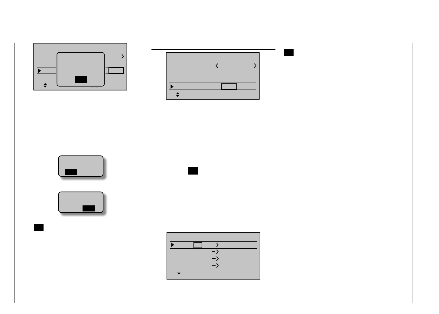
BASIC SETTINGS, MODEL
Mod.name
Stick mode
RF BIND
Rcv Ch Map
Drop down two lines in the screen and switch off the
RF module as described on the page in section "RF
module". Afterward, return again to the "RF BIND" line
and restart the process to dissolve bond as described
on the previous page.
Alternatively you can briefl y switch off the transmitter
then, after switching it back on again, respond to the
message window that appears …
… with "OFF" …
… then confi rm the selection by briefl y pressing the
center SET button in the right touch pad. From the base
screen jump again into the "RF BIND" line of the "Basic
settings, model" menu and restart the binding process.
Dissolving a bond
Proceed as described above to initiate the binding
process but WITHOUT fi rst putting a receiver in binding
readiness.
Detail program description - Base setup model
70
must be
Please select
RF on/off?
Please select
RF on/off?
ON
GRAUBELE
RF
bind
OFF
R12
OK
BD1
OFFON
OFF
1
bind
R08
BD2
Receiver change map
BASIC SETTINGS, MODEL
Mod.name
Stick mode
RF BIND
Rcv Ch Map
As mentioned in the introduction to the "Binding
receivers" section, the mx-20 HoTT offers both the
opportunity to freely divide up the transmitter's control
channels within a receiver and the opportunity to
distribute the transmitter's 12 control channels across
two receivers. This redistribution is subsequently
referred to as "mapping" or "channel mapping" (channel
correlation). Select the receiver to be "mapped" with
the arrow keys of the left or right touch pad then briefl y
press the center SET button in the right touch pad.
Channel mapping within a receiver
Analogous to the channel correlation function in the
"Telemetry" menu on page 212, described as "Channel
Mapping", it is very simple to use this menu item to
freely distribute the 12 control channels (inputs) to
the outputs (servo connections) of the bound receiver
specifi ed by column BD1.
RECEIVER CH – BIND1
In Ch 1
In Ch 2
In Ch 3
In Ch 4 Out Ch 4
After selection of the desired output with the arrow
keys of the left or right touch pad, the corresponding
GRAUBELE
1
bind
R12
BD1
Out Ch 1
Out Ch 2
Out Ch 3
bind
R08
BD2
input fi eld will be framed. Press briefl y on the center
SET button in the right touch pad. The current setting is
displayed in inverse video. Now select the desired input
channel (= transmitter output, see page 206) with the
arrow keys of the left or right touch pad.
Notice:
The number of lines available in the list (outputs)
corresponds to the maximum number of servos which
can be attached to the given receiver.
BUT CAUTION: If, for example, you have already
specifi ed "2AIL" in the "Aile/fl aps" line of the "Model
type" menu then the transmitter will have allocated
control function 2 (ailerons) for left and right ailerons to
control channels 2 & 5. The corresponding inputs (to the
receiver) in this case would be channels 2 & 5 and these
should be assigned accordingly, refer to the example
below.
Examples:
You would like to control each aileron of a large •
model with two or more servos.
Assign each of the appropriate outputs (servo
connections) to one and the same input (control
channel). In the aforementioned case, to the
giveninput of one of the two default aileron control
channels (2 & 5) appropriate for the left or right wing.
You would like to control the rudder of a large model •
with two or more servos.
Assign each of the appropriate outputs (servo
connections) to one and the same input (control
channel). In this case, the default rudder channel (4),
see fi gure bottom right.
Page 71

Important notice:
By using the mx-20 HoTT transmitter's "Tx. output
swap " option the transmitter's 12 control functions
can be freely swapped in a similar manner or multiple
outputs can be assigned to the same control function.
To avoid confusion, it is strongly recommended that only
one of these two options is used.
Channel assignment on the second receiver
As already mentioned, the "Receiver channel mapping"
option can be used to freely distribute the mx-20
HoTT transmitter's 12 control channels across two
receivers, whereby the numbering sequence of outputs
(servo connections) begun in the "BD1" column for
bound "receiver 1" will be continued. For example, if
"receiver 1" has enough connectors for 12 servos then
the numbering of outputs in the "BD2" column (for the
second bound receiver) will begin with 13.
RECEIVER CH – BIND2
In Ch12
In Ch12
In Ch12
In Ch12 Out Ch16
After selection of the desired output with the arrow
keys of the left and right touch pad, the corresponding
input fi eld will be framed. Press the center SET button
in the right touch pad The current setting is displayed
in inverse video. Now select the desired input channel
with the arrow keys of the right touch pad. For example,
suitable to the above rudder example.
Out Ch13
Out Ch14
Out Ch15
RECEIVER CH – BIND2
Input 4
Input 4
Input 4
Input 4
Notice:
The number of lines available (outputs) corresponds to
the maximum number of servos which can be connected
to receiver 2 and their numbering is dependent on the
maximum number of servos which can be connected to
receiver 1.
RF transmit
This menu line provides an option for manually
switching the transmitter's RF transmission on and off
to specifi c models while the transmitter is in operation.
For example, to save power while a model is being
programmed. If this line option was set to OFF, it
will be canceled (i.e. set to ON) the next time the
transmitter is switched on.
If necessary, use the arrow keys of the left or right
touch pad to reach the "RF transmit" line then activate
the option with by briefl y pressing the center SET button
in the right touch pad
BASIC SETTINGS, MODEL
Stick mode
RF BIND
Rcv Ch Map
RF transmit
Out Ch13
Out Ch14
Out Ch15
Out Ch16
bind
R12
bind
R08
OFF
SEL
1
between OFF and ON. Again pressing the center SET
button in the right touch pad will complete the entry.
Range test
The built-in range test reduces transmission power to an
extent that a function test can be carried out even within
a distance of up to about 50 m.
Perform the range test on the Graupner HoTT system
according to the following instructions. If necessary,
have someone assist you in carrying out the range test.
Preferably the receiver already bound to the 1.
transmitter should be installed into the model in its
intended position.
Switch remote control on and wait for the receiver's 2.
green LED to light up. Now servo movements can be
observed.
Place the model on a level surface (pavement, 3.
low-cut grass or bare ground) such that receiver
antennas are at least 15 cm above ground level. It
may be necessary to put something under the model
to raise it up enough for this.
Hold the transmitter at hip level and at some distance 4.
from one's body. Do not point the antenna directly at
the model but rather turn and/or kink the antenna's
end so that it is oriented vertically during the test.
If necessary, use the 5. arrow keys of the left or
right touch pad to reach the "RF Range Test"
the menu then start range test mode by pressing the
center SET button in the right touch pad.
line in
The right arrow keys can now be used to choose
Detail program description - Base setup model
71
Page 72

BASIC SETTINGS, MODEL
RF BIND
Rcv Ch Map
RF transmit
RF Range Test 99sec
When the range test is activated, the transmitter's
output power will be signifi cantly reduced and the
blue LED on the antenna's socket will begin to
blink. At the same time, the timer display in the
transmitter's screen will start counting down and
every 5 seconds a two-frequency tone will sound.
GRAUBELE
#01
TEST 76s
5.2V
2:22h
Five seconds prior to the end of the range test a
three-frequency tone will sound once every second.
After expiration of the range test's 99th second the
transmitter will again be switched to full output power
and the blue LED will again illuminate constantly.
Move away from the model while manipulating 6.
the joysticks during this timespan. If you notice an
interruption anytime while still within a distance of
about 50 m, try to reproduce this malfunction.
If there is a motor in the model, it may be necessary 7.
to switch it on to further check noise immunity.
Continue moving away from the model until perfect 8.
control is no longer possible.
Wait at this distance for the remainder of the test 9.
Detail program description - Base setup model
72
bind
R12
Stop
Flt
«normal »
K78
M
bind
R08
OFF
SEL
0:00
0:00
HoTT
5.5V
period with the still-operationally-ready model to
expire. After the range test is ended it should again
respond correctly to all RC controls. If this is not 100
% the case, do not use the system. Contact your
area's Graupner GmbH & Co. KG service partner.
Perform the range test before each fl ight and, in 10.
doing so, simulate all servo movements which also
take place during fl ight. The range must always be
at 50 m on the ground in order to assure safe model
operation.
Attention:
Never start the range test on the transmitter during
normal operation of the model.
DSC output
If necessary, use the arrow keys of the left or right
touch pad to reach the "DSC output"
then activate this menu item by briefl y pressing the
center SET button in the right touch pad.
BASIC SETTINGS, MODEL
Rcv Ch Map
RF transmit
RF Range Test
DSC output PPM10
Now you can use the right arrow keys to choose
between three types of modulation "PPM10", "PPM18"
and "PPM24". Pressing the center SET button in the
right touch pad again will complete the entry.
This choice primarily infl uences the maximum number
of control channels which can be attached to the DSC
(direct servo control) socket, and thus also available to
a fl ight simulator or teacher/pupil system. This maximum
line of the menu
R12
R08
OFF
99sec
SEL
is control channels 1 ... 5 if "PPM10" is selected, control
channels 1 ... 9 for "PPM18" and control channels 1 ...
12 for "PPM24".
Cut-off
Depending on the "idle forward or back" choice made
in the "Motor at C1" line of the "Model type" menu, this
motor "cut off" option can be coupled to a switch for
throttling down a speed controller or to move a servo on
the carburetor of a motor to the OFF (or idle) position.
The motor OFF position (or idle setting) will then
be preset by the left column directly over the "SEL"
fi eld. The appropriate value for this entry fi eld is to be
established through trial and error
A speed controller or throttle servo will only take on
this preset position when a certain servo position or
threshold is underrun and a switch is activated. This is
done by setting the desired servo position (threshold
value) into the middle column, directly over the "STO"
fi eld then selecting the appropriate ON/OFF switch
function in the right column.
If the percentage value specifi ed for the middle •
column is greater than the current servo position, i. e.
the current servo position lies below the threshold,
the switchover will occur as soon as the switch is put
into its ON position.
If the percentage value specifi ed for the middle •
column is less than the current servo position, i. e.
the current servo position is above the threshold, the
speed controller will initially reduce motor speed or
close the carburetor's throttle servo only to the extent
dictated by the value in the left column as soon as
the servo's position once underrunsthe threshold
(max. +150 %) after the switch is changed over to its
Page 73

ON position.
The speed controller or throttle servo will remain in
this cut-off position only until the selected switch is
again changed over followed by a one-time throttle
servo or speed controller movement beyond the preset
threshold with the throttle/brake joystick control.
The factory setting for the left column is -100 % for
the throttle servo "cut-off" position and a threshold of
+150 % servo position setting in the middle column.
speed controller, alone by the switch to be assigned in
the right column.
However, if you wish to set a lower threshold, by which
an underrun will cause the throttle servo or speed
controller with closed switch to switch into the cut-off
position, reduce the preset servo travel from +150 %
by placing the throttle servo or speed controller into
the desired position with the throttle/brake joystick then
press the center
SET button in the right touch pad.
BASIC SETTINGS, MODEL
99sec
PPM10
STO
99sec
PPM10
+150%
STO
OFF
–––
OFF
–––
RF transmit
RF Range Test
DSC Output
cut off +150%–100%
SEL
Programming
To change the preset "cut-off" position of the throttle
servo, press the center SET button in the right touch
pad. The current setting will be displayed in inverse
video. Now use the arrow keys of the left or right touch
pad to set a value at which the motor is reliably "off". If a
combustion motor is involved, be sure the throttle servo
does not perform mechanical runout, e. g. -125 %.
BASIC SETTINGS, MODEL
RF transmit
RF Range Test
DSC output
cut off
The – upper – preset value in the middle column
ensures the motor can be stopped, throughout the
maximum possible positioning range of the servo or
–125%
SEL
BASIC SETTINGS, MODEL
RF transmit
RF Range Test
DSC output
cut off
Finally, use the column at the right to specify a
switch with which you can cut off the motor directly
(emergency) or which will be activated by the threshold.
BASIC SETTINGS, MODEL
RF transmit
RF Range Test
DSC output
cut off
Notices:
Be sure the throttle servo does not run out •
mechanically when the cut-off function is activated.
A threshold over +100 % is reached by temporarily •
increasing the travel for servo 1 in the "Servo
adjustment" menu to over 100 % then, after storing
the threshold, change servo travel back to the
original value.
–125% +100%
SEL
–125% +100%
SEL
OFF
99sec
PPM10
–––
STO
OFF
99sec
PPM10
8
STO
Detail program description - Base setup model
73
Page 74

Base setup model
Model-specifi c base settings for helicopter models
Before programming specifi c parameters, there are
some basic settings to be made which effect the
currently active model memory. Select the "Base setup
model " menu with the arrow keys of the left or right
touch pad then press the center
touch pad.
Suppress models
Base setup model
Helicopter type
Servo adjustment
Stick mode.
Control adjust
Model name
BASIC SETTINGS, MODEL
Mod.name
Stick mode
RF BIND
RF transmit OFF
Change to the next screen page by briefl y pressing
the SET button in the right touch pad. This will open
a screen of characters for entry of the model's name.
A maximum of 9 characters can be used to specify a
model name.
!"#$%&’()+,–./012
3456789:;
FGHIJKL MNOPQRSTUVWX
YZ[¥]^_`abcdefghijk
Mod Name
Detail program description - Base setup model | Helicopter
74
SET button in the right
n/a
BD1
BD2
?@ABCDE
STARL
1
n/a
Select the desired characters with the arrow keys of the
left touch pad. Move to select the next character position
by pressing the arrow key of the right touch pad or its
SET button Simultaneously pressing on the
center
or keys of the right touch pad (CLEAR) will place a
space character at the position.
Positioning to any character position within the entry fi eld
can be done with the keys of the right touch pad.
A return to the previous menu screen is accomplished
by pressing the center ESC button in the left touch pad.
A model name entered in this manner will appear in the
base screen of the "Model select" menu and in the submenus of the "Copy / Erase" menu item.
Stick mode
"MODE 1" (throttle left)
TS-Nick
Tail
Nick
"MODE 3" (throttle right)
Nick
Roll
Nick
Motor/Pitch
Tail
Roll
Motor/Pitch Motor/Pitch
Motor/Pitch
Roll
Tail
Motor/Pitch
"MODE 2" (throttle left)
Motor/Pitch
Roll
Tail
"MODE 4" (throttle left)
Motor/Pitch
Tail
Roll
Motor/Pitch
Tail
Roll
Nick
Roll
Roll
Nick
Nick
Tail
Tail
Nick
Basically there are four different ways to assign the
four helicopter control functions, roll, nick, tail rotor and
throttle/pitch to the two joysticks. Just which of these
is used depends on the preferences of the individual
model pilot.
Use the arrow keys of the left or right touch pad
to select the "Stick mode" line. The option fi eld will be
framed.
BASIC SETTINGS, MODEL
Mod.name
Stick mode
RF BIND
STARLET
n/a
1
n/a
RF transmit OFF
SEL
Press the SET button. The currently displayed stick
mode will be displayed in inverse video. Now use the
arrow keys of the right touch pad to select from among
options 1 through 4.
Pressing simultaneously on the or keys of the
right touch pad (CLEAR) will return the option selection
back to stick mode "1".
Pressing the SET button again will deactivate option
selection so that you can change to another line.
Bound receiver
Graupner-HoTT receivers must be "instructed " to
communicate exclusively with one particular model
(memory) in a Graupner-HoTT transmitter. This
procedure is known as "binding" and must only be done
once for every new receiver/model memory location
combination (and can be repeated anytime).
Important notice:
During the binding procedure be sure the
transmitter's antenna is always far enough away
from the receiver's antenna. To be on the safe side,
keep them at least one meter apart. Otherwise you
run the risk of a faulty connection to the return
channel and malfunctions will result.
"Binding" multiple receivers per model
Multiple receivers per model can be bound if desired,
Page 75

whereby respective mx-20 HoTT programs offer the
potential for managing a maximum of two receivers
directly and for dividing up the 12 control channels (max)
available on these two receivers as desired under menu
control. Refer to additional details further down in this
section. Binding two receivers is begun by fi rst binding
the individual receivers as described below.
In subsequent operation of the model only one of
these receivers will establish a telemetry bond to
the transmitter; the one which was activated in
the "Tel. RCV" line of the "Telemetry" menu. For
example:
TELEMETRY
TEL.RCV
SETTING & DATA VIEW
SENSOR SELECT
RF STATUS VIEW
VOICE TRIGGER
BIND. 1
Any telemetry sensors which may be built into the model
should therefore be connected to this receiver because
the transmitter only receives and evaluates data from
the return channel of the receiver activated on this line.
The second, and all other receivers, operate in parallel
but are fully independent in slave mode.
"Binding" the transmitter and receiver
Use arrow keys of the left or right touch pad to
move to the screen's "RF bind" line then select the
desired binding channel. For an example like that shown
in the figure below, choose "BD2" because the binding
channel designated as "BD1" in the screen's bottom line
is already used by default for the receiver which was
delivered with the set.
BASIC SETTINGS, MODEL
Mod.name
Stick mode
RF BIND
Rcv Ch Map
STARLET
bind
R12
BD1
1
n/a
n/a
BD2
If not already off, now switch the receiver on. The red
LED on the receiver will blink.
Press and hold the SET button on the receiver while
the LED continues to blink red for about 3 seconds then
after about another 3 seconds begins to blink red/green.
You can now release the SET button As long as this
LED blinks red/green, the receiver is in bind mode.
Now, within this 3 second period, start the so-called
"receiver binding" process for the receiver to the
currently active model memory by briefl y pressing the
center SET button of the right touch pad. At this time the
screen's display will begin to indicate the duration of the
"bond".
BASIC SETTINGS, MODEL
Mod.name
Stick mode
RF BIND
Finding ...
Rcv Ch Map
STARLET
bind
R12
BD1
1
n/a
n/a
BD2
If the receiver's LED, again blinking red, changes within
about 10 seconds to continuous illumination in green,
the binding process has been successfully completed.
Your model-memory to receiver combination is now
operationally ready. At this time the screen will now
display "bind" (bound) instead of "n/a" (not attached).
For example:
BASIC SETTINGS, MODEL
Mod.name
Stick mode
RF BIND
Rcv Ch Map
STARLET
bind
R12
BD1
1
bind
R08
BD2
On the other hand, should the LED on the receiver
blink red for longer than about 10 seconds, the binding
process has failed. In this case the screen will continue
to show the status as "n/a". If this should happen, try
changing the position of antennas then repeat the entire
procedure.
Binding other receivers
The binding channel you have chosen is already bound
(as indicated by the "bind" status). with another binding
channel. If, after initiating the RF bind process, the
message shown below appears in the screen instead of
displaying "BINDING"
Detail program description - Base setup model | Helicopter
75
Page 76

BASIC SETTINGS, MODEL
Mod.name
Stick mode
RF BIND
Rcv Ch Map
Drop down two lines in the screen and switch off the
RF module as described on the page in section "RF
module". Afterward, return again to the "RF BIND" line
and restart the process to dissolve bond as described
on the previous page.
Alternatively you can briefl y switch off the transmitter
then, after switching it back on again, respond to the
message window that appears …
… with "OFF" …
… then confi rm the selection by briefl y pressing the
center SET button in the right touch pad. From the base
screen jump again into the "RF BIND" line of the "Basic
settings, model" menu and restart the binding process.
Dissolving a bond
Proceed as described above to initiate the binding
process but WITHOUT fi rst putting a receiver in binding
readiness.
Detail program description - Base setup model | Helicopter
76
must be
Please select
RF on/off?
ON
Please select
RF on/off?
ON
RF
OFF
OK
OFF
OFF
STARLET
bind
R12
BD1
1
bind
R08
BD2
Receiver change map
BASIC SETTINGS, MODEL
Mod.name
Stick mode
RF BIND
Rcv Ch Map
As mentioned in the introduction to the "Binding
receivers" section, the mx-20 HoTT offers both the
opportunity to freely divide up the transmitter's control
channels within a receiver as well as the opportunity to
distribute the transmitter's 12 control channels across
two receivers. This redistribution is subsequently
referred to as "mapping" or "channel mapping" (channel
correlation). Select the receiver to be "mapped" with
the arrow keys of the left or right touch pad then briefl y
press the center SET button in the right touch pad.
Channel mapping within a receiver
Analogous to the channel correlation function in the "
Telemetry " menu on page 212, described as "Channel
Mapping", it is very simple to use this menu item to
freely distribute the 12 control channels (inputs) to
the outputs (servo connections) of the bound receiver
specifi ed by column BD1.
RECEIVER CH – BIND1
In Ch 1
In Ch 2
In Ch 3
In Ch 4 Out Ch 4
After selection of the desired output with the arrow keys
of the left and right touch pad, the corresponding input
STARLET
bind
R12
BD1
Out Ch 1
Out Ch 2
Out Ch 3
bind
1
R08
BD2
fi eld will be framed. Press briefl y on the center SET
button in the right touch pad. The current setting will be
displayed in inverse video. Now select the desired input
channel (= transmitter output, see page 206) with the
arrow keys of the left or right touch pad.
Notice:
The number of lines available in the list (outputs)
corresponds to the maximum number of servos which
can be attached to the given receiver.
BUT CAUTION: If you wish to operate two servos with
one control function, for example such as transmitter
control function 2 (roll) which is divided up into
control channels 1 & 2 for left and right roll servos by
"3Sv(2Roll)" in the " in the "Heli Type" menu; then
"map" transmitter outputs 1 & 2 (= inputs to the receiver)
accordingly.
Important notice:
By using the mx-20 HoTT transmitter's "Tx. output
swap" option, the transmitter's 12 control functions
can be freely swapped in a similar manner or multiple
outputs can be assigned to the same control function.
To avoid confusion, it is strongly recommended that only
one of these two options is used.
Channel assignment on the second receiver
As already mentioned, the "Receiver channel mapping"
option can be used to freely distribute the mx-20
HoTT transmitter's 12 control channels across two
receivers, whereby the numbering sequence of outputs
(servo connections) begun in the "BD1" column for
bound "receiver 1" will be continued. For example, if
"receiver 1" has enough connectors for 12 servos then
the numbering of outputs in the "BD2" column (for the
Page 77

second bound receiver) will begin with 13.
RECEIVER CH – BIND2
In Ch12
In Ch12
In Ch12
In Ch12 Out Ch16
After selection of the desired output with the arrow keys
of the left and right touch pad, the corresponding input
fi eld will be framed. Press the center SET button in the
right touch pad The current setting will be displayed
in inverse video. Now select the desired input channel
with the arrow keys of the right touch pad. For example,
appropriate for the above example with roll servos:
RECEIVER CH – BIND1
In Ch 1
In Ch 2
In Ch12
In Ch12
Notice:
The number of lines available (outputs) corresponds to
the maximum number of servos which can be connected
to receiver 2 and their numbering is dependent on the
maximum number of servos which can be connected to
receiver 1.
RF transmit
This menu line provides an option for manually
switching the transmitter's RF transmission on and off
to specifi c models while the transmitter is in operation.
For example, to save power while a model is being
Out Ch13
Out Ch14
Out Ch15
Out Ch13
Out Ch14
Out Ch15
Out Ch16
programmed. If this line option was set to OFF, it
will be canceled (i.e. set to ON) the next time the
transmitter is switched on.
If necessary, use the arrow keys of the left or right
touch pad to reach the "RF transmit " line then activate
bind
R12
SET button in
1
bind
R08
OFF
SEL
the option by briefl y pressing the center
the right touch pad.
BASIC SETTINGS, MODEL
Stick mode
RF BIND
Rcv Ch Map
RF transmit
The right arrow keys can now be used to choose
between OFF and ON. Again pressing the center SET
button in the right touch pad will complete the entry.
Range test
The built-in range test reduces transmission power to an
extent that a function test can be carried out even within
a distance of up to about 50 m.
Perform the range test on the Graupner HoTT system
according to the following instructions. If necessary,
have someone assist you in carrying out the range test.
Preferably the receiver already bound to the 1.
transmitter should be installed into the model in its
intended position.
Switch remote control on and wait for the receiver's 2.
green LED to light up. Now servo movements can be
observed.
Place the model on a level surface (pavement, 3.
low-cut grass or bare ground) such that receiver
antennas are at least 15 cm above ground level. It
may be necessary to put something under the model
to raise it up enough for this.
Hold the transmitter at hip level and at some distance 4.
from one's body. Do not point the antenna directly at
the model but rather turn and/or kink the antenna's
end so that it is oriented vertically during the test.
If necessary, use the 5. arrow keys of the left or
right touch pad to reach the "RF Range Test" line in
the menu then start range test mode by pressing the
SET button in the right touch pad.
center
BASIC SETTINGS, MODEL
RF BIND
Rcv Ch Map
RF transmit
RF Range Test 99sec
When the range test is activated, the transmitter's
output power will be signifi cantly reduced and the
blue LED on the antenna's socket will begin to
blink. At the same time, the timer display in the
transmitter's screen will start counting down and
every 5 seconds a two-frequency tone will sound.
STARLET
#02
TEST 76s
5.2V
2:22h
Five seconds prior to the end of the range test a
three-frequency tone will sound once every second.
After expiration of the range test's 99th second the
transmitter will again be switched to full output power
bind
R12
Stop
Flt
«normal »
K78
M
bind
R08
OFF
SEL
0:00
0:00
HoTT
5.5V
Detail program description - Base setup model | Helicopter
77
Page 78

and the blue LED will again illuminate constantly.
Move away from the model while manipulating 6.
the joysticks during this timespan. If you notice an
interruption anytime while still within a distance of
about 50 m, try to reproduce this malfunction.
If there is a motor in the model, it may be necessary 7.
to switch it on to further check noise immunity.
Continue moving away from the model until perfect 8.
control is no longer possible.
Wait at this distance for the remainder of the test 9.
period with the still-operationally-ready model to
expire. After the range test is ended it should again
respond correctly to all RC controls. If this is not
100 % the case, do not use the system. Contact your
area's Graupner GmbH Co. KG service partner.
Perform the range test before each fl ight and, in 10.
doing so, simulate all servo movements which also
take place during fl ight. The range must always be
at 50 m on the ground in order to assure safe model
operation.
Attention:
Never start the range test on the transmitter during
normal operation of the model.
DSC output
If necessary, use the arrow keys of the left or right
touch pad to reach the "DSC output"
this menu item by pressing the center SET button of the
right touch pad.
line then activate
BASIC SETTINGS, MODEL
Rcv Ch Map
RF transmit
RF Range Test
DSC output PPM10
Now you can use the right arrow keys to choose
between three types of modulation "PPM10", "PPM18"
and "PPM24". Pressing the center SET button in the
right touch pad again will complete the entry.
This choice primarily infl uences the maximum number
of control channels which can be attached to the DSC
(direct servo control) socket, and thus also available to
a fl ight simulator or teacher/pupil system. This maximum
is control channels 1 ... 5 if "PPM10" is selected, control
channels 1 ... 9 for "PPM18" and control channels 1 ...
12 for "PPM24".
Autorotation
Autorotation is that state of descending fl ight in which
the pitch of main rotor blades are set such that the
rotor's speed matches the natural forces of air fl owing
through, like a windmill. This built-up energy can be
used for "recovery" lift to brake a descent by appropriate
blade pitch adjustment.
Autorotation is a means by which real and model
helicopters are able to land safely in emergency
situations, e. g. in the event of a motor failure. However,
the prerequisite for this is a well-trained pilot familiar
with the helicopter's characteristics. Quick reaction and
good perceptiveness are necessary because the rotor's
inertia can only be used once to generate recovery lift.
When this technique is evaluated during competitions,
R12
R08
OFF
99sec
SEL
the motor must be switched off for autorotation. For
training purposes it is better to keep the motor running
at idle during autorotation.
The Autorotation switch causes a switchover to the
autorotation fl ight phase in which control of "throttle" and
"pitch" are separate and all mixers which have an effect
on the throttle servo are switched off. Corresponding
parameter settings are made in the "Helicopter mixer"
menu (see page 178); refer also to the "Principle of the
Auto. C1 Pos." topic which follows.
The "Autorotation" name is permanently assigned to
phase 1 and it is included in the base screen of all
fl ight phase dependent menus. This name can NOT
be changed. It is only possible to assign a switch to
this option, as described on page 52. If a switch is
assigned, it will have absolute priority over all other
fl ight-phase switches.
C1
Thr
Curve
Input
Output
Point
Normal
More about fl ight-phase programming can be found
in the text beginning on page 164 in the "Helicopter
mixer" section.
Auto.C1 Pos. (Autorotation C1 position)
The autorotation fl ight-phase can alternatively be
activated by a threshold point for the C1 throttle/pitch
joystick. To set such a threshold, use the arrow
keys of the left or right key pad to reach the "Auto.C1
Pos." line.
off
?
–100%
0%
0%
Detail program description - Base setup model | Helicopter
78
Page 79

As soon as this line has been selected, the value fi eld
in its column directly above STO on the screen's bottom
line will be framed.
BASIC SETTINGS, MODEL
RF Range Test
DSC Output
Autorotation
Auto.C1 Pos. 0%
Move the C1 joystick into the desired threshold
switchover position then press the center SET button in
the right touch pad. The current value will be displayed,
e. g.:
BASIC SETTINGS, MODEL
RF Range Test
DSC Output
Autorotation
Auto.C1 Pos.
After this has been done, use the arrow keys to move
into the column above the switch symbol then assign a
switch to this fi eld, as described on page 52 in section
"Switches, controls and control switches". Preferably the
selection will be one of the two self-resetting switches,
SW 1 or 9.
BASIC SETTINGS, MODEL
RF Range Test
DSC Output
Autorotation
Auto.C1 Pos.
99sec
PPM10
STO
99sec
PPM10
-55%
STO
99sec
PPM10
-55%
STO
–––
–––
–––
–––
–––
9
Once this activation switch is closed, the fi rst occurrence
of a threshold underrun will cause the program to switch
over to "Autorotation" and then remain independent of
C1 position in this fl ight phase until the activating switch,
in this example SW 9, is again "OFF".
"Auto. C1 Pos." has precedence over all other fl ightphase switches.
Corresponding parameter settings for …
pitch servos•
throttle servo•
tail rotor servo•
swashplate rotation, if available•
gyro setting•
… are made in the "Helicopter mixer" menu, see
page 64.
Cut-off
Within the framework of autorotation settings for the
mx-20 HoTT transmitter's helicopter program, there
are parameters for an emergency "cut off" of the throttle
servo or motor actuator, refer to the programming
proposal on page 286. However, this option is not
available if an idle position is specifi ed in the "Thr
setting AR" line of the "Helicopter mixer" menu
instead of an (emergency) OFF position; for example,
to avoid restarting the motor after every landing during
autorotation practice. In this case it is better to use this
option as a "cut off" rather than as an emergency OFF
solution.
Depending on the "forw./back" choice made for the
"Pitch min" line of the "Heli Type" menu, this motor "cut
off" option can be coupled to a switch for throttling down
a carburetor servo to the cut-off (or idle) position.
This cut-off (or idle) position is specifi ed by the left
Detail program description - Base setup model | Helicopter
column over the "SEL" fi eld and its value is to be
established through trial and error.
A speed controller or throttle servo will only take on
this preset position when a certain servo position or
threshold is underrun and a switch is activated. This is
done by setting the desired servo position (threshold
value) into the middle column, directly over the "STO"
fi eld then selecting the appropriate ON/OFF switch
function in the right column.
If the percentage value specifi ed for the middle •
column is greater than the current servo position, i. e.
the current servo position lies below the threshold,
the switchover will occur as soon as the switch is put
into its ON position.
If the percentage value specifi ed for the middle •
column is less than the current servo position, i. e.
the current servo position is above the threshold, the
speed controller will initially reduce motor speed or
close the carburetor's throttle servo only to the extent
dictated by the value in the left column as soon as
the servo's position once underruns the threshold
(max. +150 %) after the switch is changed over to its
ON position.
The speed controller or throttle servo will remain in
this cut-off position only until the selected switch is
again changed over followed by a one-time throttle
servo or speed controller movement beyond the
preset threshold with the throttle/brake joystick
control.
The factory setting for the left column is -100 % for
the throttle servo "cut-off" position and a threshold of
+150 % servo position setting in the middle column.
79
Page 80

BASIC SETTINGS, MODEL
DSC Output
Autorotation
Auto.C1 Pos.
cut off +150%–100%
SEL
PPM10
-55%
STO
–––
9
–––
BASIC SETTINGS, MODEL
DSC Output
Autorotation
Auto.C1 Pos.
cut off
–125%
SEL
PPM10
-55%
+100%
STO
–––
9
–––
Programming
To change the preset "cut-off" position of the throttle
servo, press the center SET button in the right touch
pad. The current setting will be displayed in inverse
video. Now use the arrow keys of the left or right touch
pad to set a value at which the motor is reliably "off"
without a startup of the throttle servo. For example
-125 %:
BASIC SETTINGS, MODEL
DSC Output
Autorotation
Auto.C1 Pos.
–125%cut off
SEL
The – upper – preset value in the middle column
ensures the motor can be stopped, throughout the
maximum possible positioning range of the servo or
speed controller, alone by the switch to be assigned in
the right column.
However, if you wish to set a lower threshold, by
which an underrun will cause the throttle servo or
speed controller with closed switch to switch into the
cut-off position, reduce the preset servo travel and - if
applicable, the throttle limiter - by placing the throttle/
pitch joystick into the desired position then press the
center SET button in the right touch pad.
Detail program description - Base setup model | Helicopter
80
PPM10
-55%
+150%
STO
–––
9
–––
Finally, use the column at the right to specify a
switch with which you can cut off the motor directly
(emergency) or which will be activated by the threshold.
BASIC SETTINGS, MODEL
DSC Output
Autorotation
Auto.C1 Pos.
cut off
Notices:
Be sure the throttle servo does not run out •
mechanically when the cut-off function is activated.
A threshold over +100 % is reached by temporarily •
increasing the travel for servo 1 in the "Servo
adjustment" menu to over 100 % then, after storing
the threshold, change servo travel back to the
original value.
–125% 1
SEL
PPM10
-55%
+100%
STO
–––
9
Page 81

Your notes
81
Page 82

Model type
Establishing winged aircraft model type
This "Model type" menu is used to establish the
type of model to be programmed. This also activates
all characteristic mixers, coupling functions, etc.
in preparation for subsequent programming of the
specifi ed model type.
Suppress model
Base setup model
Model type
Servo adjustment
Stick mode.
Control adjust
Press briefl y on the center SET button in the right touch
pad.
Motor at C1
After selecting the "Motor at C1" line with the arrow
keys of the left and right touch pad, the corresponding
entry fi eld will be framed.
M O D E L T Y P E
Motor at C1
Tail type
Aile/flaps
Brake Off In 1+100%
Press briefl y on the center SET button in the right touch
pad. The current setting will be displayed in inverse
video. Now use the arrow keys of the right touch pad to
select from among the following four options:
"none" For operation of a model without a
propulsion.
The warning "Throttle too high", see
page 36, is deaktivated and the "Brake
None
Normal
1AIL
SEL
settings" sub-menu of the "Wing
mixers" menu (beginning page 146) is
available without any restrictions.
"back": The idle position for the throttle/brake
fl aps control stick (C1) is to the rear, i. e.
toward the pilot.
The warnings "Throttle too high", see
page 36, as well as the "cut off" option
in the "Basic settings, model" menu,
see page 72, are activated and the
"Brake settings" sub-menu of the "Wing
mixers", beginning page 146, will be
available if the entry in the "Motor"
column of the "Phase settings" menu,
page 128 for the currently active fl ight
phase contains "none".
"forw.": The idle position for the throttle/brake
fl aps control stick (C1) is at the front, i. e.
away from the pilot.
The warnings "Throttle too high", see
page 36, as well as the "cut off" option
in the "Basic settings, model", see
page 72, are activated and the "Brake
settings" sub-menu of the "Wing
mixers", beginning page 146, will be
available if the entry in the "Motor"
column of the "Phase settings" menu,
page 128 for the currently active fl ight
phase is "none".
Notice:
Be sure to pay attention during the programming •
procedures that motors do not start up
unintentionally. Disconnect the fuel supply or
battery terminals to motors before programming.
C1 trimming will operate according to your choice •
between "normal" or only "back" or "fwd.", that is,
either over the control's entire travel path or only in
the respective idle direction.
Pay attention to the "• cut off trim" function described
on page 54.
Tail type
After selecting the "Tail type" line with the arrow
keys of the left or right touch pad, the corresponding
entry fi eld will be framed.
M O D E L T Y P E
Motor at C1
Tail type
Aile/flaps
Brake Off In 1
Press briefl y on the center SET button in the right touch
pad. The current setting will be displayed in inverse
video. Now select the type applicable to your model with
the arrow keys of the right touch pad.
"normal": Elevators and rudder are each operated
by a single servo.
"V-tail": Elevator and rudder control is affected
by way of two separate, articulated,
V-shaped rudders. The coupling function
for rudder and elevator control will be
automatically taken over by the program.
The relationship of rudder-to-elevator
proportion is set in the "Dual Rate /
Expo" menu, page 108 and servo travel
in the "Servo adjust" menu, page 90.
If differentiated rudder throw is also
desired then the V-tail should be
+100%
None
Normal
1AIL
SEL
Detail program description - Model type
82
Page 83

controlled instead by way of the "Dual
mixer" menu, page 194. In this case
however, the tail type entry specifi ed here
must be "normal".
"Delta/fl ": Aileron and elevator control is operated
by one or two servos per wing half.
However, elevator trimming is also
affected by selecting the "QR 2WK"
option – see below – but only on servos 2
& 3.
"2HRSv3+8": This option is intended for models
with two elevator servos. The servo
connected to output 8 will operate in
parallel with servo 3 to actuate elevators.
Elevator trimming affects both servos.
Notice about the "2HRSv3+8" option:
One control, which assigns input 8 by
way of the "Control adjust" menu, is
then disconnected from servo "8" by
software for reasons of safety i. e. it is
made ineffective.
Aileron/Flaps
After selecting the "Aile/fl aps" line with the arrow
keys of the left or right touch pad, the corresponding
entry fi eld will be framed.
M O D E L T Y P E
Motor at C1
Tail type
Aile/flaps
Brake Off In 1
Press briefl y on the center SET button in the right touch
pad. The current setting will be displayed in inverse
+100%
None
Normal
1AIL
SEL
video. Now use the arrow keys of the right touch pad to
select the number of wing servos to be programmed for
the model.
Available Control channel used
1QR 2
1QR 1WK 2 | 6
2QR 2 + 5
2QR 1WK 2 + 5 | 6
2QR 2WK 2 + 5 | 6 + 7
2QR 4WK 2 + 5 | 6 + 7 / 9 + 10
4QR 2WK 2 + 5 / 11 + 12 | 6 + 7
4QR 4WK 2 + 5 / 11 + 12 | 6 + 7 / 9 + 10
Depending on the option selected here, the given mixers
needed and their settings will be activated in the "Wing
mixers", menu beginning page 146.
Tips:
Settings for all wing fl ap pairs (QR and QR2, WK and •
WK2) can be trimmed on a fl ight-phase basis in both
the "Phase trim" menu and in the "Wing mixers"
menu, page 146.
The functionality of all wing fl ap pairs (QR and QR2, •
WK and WK2) can also be operated by way of the
"Throttle/brake-fl ap stick" if this stick has not been
assigned to other use, e. g. for certain brake settings,
see "Wing mixers" menu, page 146. To confi gure
this it is only necessary to assign "Control 1" to input
6 in the "Control adjust" menu, page 96. (If you
would rather operate fl aps with switches, one of the
transmitter's two or three position switches are good
for this purpose.)
Brake offset
This function not only has potential for gliders and
electric models but also for models with combustion
motors and landing fl aps.
The mixers described in the "Brake settings" line of
the "Wing mixers" menu can be operated by the C1
control stick ("input 1") or another transmitter operating
element which has been assigned to input 7, 8 or 9 in
the "Control adjust" menu. In this latter case, retain
the "GL" default setting for the "Type" column in the
"Control adjust" menu so the selected control can
operate independent of fl ight phase.
In the majority of cases the default setting for "input 1"
will remain as it is and the brake will be operated by way
of the non-neutralizing C1 joystick.
However, use of input 7, 8 or 9 makes it possible to
operate the brake in an alternative manner, even by way
of a supplementary control, if the C1 stick is to be used
for something else.
The neutral point (offset) can be set to any desired
position. This is done by placing the control for input 1,
7, 8 o 9 into the position at which the landing fl aps are to
be in their neutral position then fi xing this "Offset" point
there with STO.
M O D E L T Y P E
Motor at C1
Tail type
Aile/flaps
Brake Off In 1
If the offset point is not set at the far end of control
element travel, the remainder of travel to the end point
will be "free travel", i. e. this "free travel" will no longer
Detail program description - Model type
+90%
None
Normal
1AIL
SELSTO
83
Page 84

infl uence any mixer available for "Brake settings" in
the "Wing mixers" menu. This free travel ensures that,
even if the brake fl ap control is not quite positioned to
its full end of travel, it will still stop all brake settings at
"neutral". At the same time, the effective control path is
automatically spread to 100 %.
Tip:
Preferably, the servo intended for operating any airbrake
fl aps that may be on the model should be connected to
the receiver output operated by the brake input channel,
e. g. connect airbrake servo onto (free) receiver output 8
if input 8 has been chosen for the "brake", etc. A second
airbrake servo is most conveniently operated by way of
a free mixer.
Detail program description - Model type
84
Page 85

Your notes
85
Page 86

Helicopter type
Establishing helicopter model type
This "Model type" menu is used to establish the
type of model to be programmed. This also activates
all characteristic mixers, coupling functions, etc.
in preparation for subsequent programming of the
specifi ed model type.
Suppress models
Base setup model
Helicopter type
Servo adjustment
Stick mode
Control adjust
Press briefl y on the center SET button in the right touch
pad.
Swashplate type
Control of the swashplate will require an appropriate
program variant which corresponds to the number of
servos operating pitch control.
After selecting the "Swashplate" line with the
arrow keys of the left or right touch pad, the
corresponding entry fi eld will be framed.
HELI TYPE
Swashplate
Linear. swashpl.
Rotor direct
Pitch min. back
Press briefl y on the center SET button in the right touch
pad. The current setting for number of pitch servos will
be displayed in inverse video. Now choose the variant
needed with the arrow keys of the right touch pad.
1 Servo
no
right
SEL
"1 Servo": The swashplate will be tipped with one
servo each for roll and nick. Pitch control
will be affected by a separate servo.
(Since helicopter models operated
with only 1 pitch servo will be operated
WITHOUT the transmitter's mixer
functions for pitch, nick and roll, the
"Swashplate mixer" menu item in the
Multifunction menu will be hidden.)
"2 Servos": Two roll servos will displace the
swashplate axially to affect pitch control;
nick control will be decoupled by a
mechanical compensation rocker.
"3Sv (2Roll)": Symmetrical three-point control of
the swashplate is affected at three
articulation points, each radially offset
from the others by 120°, which are
connected to one nick servo (at the
front orrear) and two roll servos (located
laterally at the left and right). All three
servos push the swashplate axially to
affect pitch control.
"3Sv (140)": Asymmetrical three-point control of
the swashplate is affected at three
articulation points connected to one nick
servo (rear) and two roll servos (front
left and right). All three servos push the
swashplate axially to affect pitch control.
"3Sv (2Nick)": Symmetrical three-point control as
described above but radially offset by
90°, one lateral roll servo and two nick
servos, front and rear.
"4Sv (90°)": Four-point swashplate control affected by
two roll servos and two nick servos.
Simultaneously pressing the or keys of the
right touch pad (CLEAR) will set the option back to
"1 Servo".
Swashplate type: 1 Servo
2
Swashplate type: 2 Servos
2
1
Swashplate type: 3 Servos (2 Roll)
2
1
3
Swashplate type: 3 Servos (140°)
2
3
Detail program description - Helicopter type
86
Page 87

Swashplate type: 3 Servos (2 Nick)
1
3
2
Swashplate type: 4 Servos (90°) 2 Nick / 2 Roll
2
5
3
1
Notice:
Except for the "1 Servo" choice, swashplate mixer
proportions must also be set in the "Swashplate mixer"
menu, page 196.
Swashplate linearizing
After selecting the "Linear. swashpl." line with the
arrow keys of the left or right touch pad, the
corresponding entry fi eld will be framed.
HELI TYPE
Swashplate
Linear. swashpl.
Rotor direct
3Sv(2rol)
no
right
Pitch min. back
SEL
The "yes" entry will prevent undesired side effects
such as pitch change due to a roll function or tension
between swashplate servo rods.
This type of tension can arise when effected servos
strain for different displacement positions due to travel
which deviates from one another.
Linearizing will require a bit of familiarization on
the part of the pilot because, in order to linearize
the entire rotation travel for the servo arm, servo
travel can be appropriately reduced for small control
movements – similar to a substantial Expo setting – .
Rotor rotation
After selecting the "Rotor direct" line (rotor direction)
with the arrow keys of the left or right touch pad,
the corresponding entry fi eld will be framed.
HELI TYPE
Swashplate
Linear. swashpl.
Rotor direct
3Sv(2rol)
no
right
Pitch min. back
SEL
Once the choice for main rotor rotation direction is made
with the arrow keys, it is set by pressing the center SET
button in the right touch pad.
"right": The main rotor turns clockwise when viewed
from above.
"left": The main rotor turns counter-clockwise when
viewed from above.
Simultaneously pressing the or keys of the
right touch pad (CLEAR) will set the option to "right".
right-hand
rotation
left-hand
rotation
This entry is necessary for correct operational
orientation of the torque and power compensation mixer
settings made in the "Helicopter mixer" menu:
Pitch,
C1 throttle,
C1 tail rotor,
Tail rotor throttle,
Roll throttle,
Roll tail rotor,
Pitch throttle,
Nick throttle,
Nick tail rotor.
Pitch min
After selecting the "Pitch min" (pitch minimum) line with
the arrow keys of the left or right touch pad, the
corresponding entry fi eld will be framed.
HELI TYPE
Swashplate
Linear. swashpl.
Rotor direct
3Sv(2rol)
no
right
Pitch min. back
SEL
Detail program description - Helicopter type
87
Page 88

The "Pitch min" line is used to adapt the direction of
operation for the throttle/pitch control stick to your
control preferences. All other helicopter program options
which involve throttle and pitch functions, e. g. throttle
curve, idle trimming, tail rotor mixer, etc., are dependent
on this setting.
Press the center
SET button in the right touch pad.
The operating direction of the throttle/pitch joystick will
be displayed in inverse video. Now choose the variant
needed with the arrow keys of the right touch pad.
Pitch
These mean:
"fwrd.": minimum pitch setting when the pitch joystick
(C1) is "forward", i.e. away from the pilot.
"back": minimum pitch setting when the pitch joystick
(C1) is "back", i.e. toward the pilot.
Simultaneously pressing the or keys of the
right touch pad (CLEAR) will set this option to "rear".
Notices:
C1 trimming affects only the throttle servo. •
The so-called "throttle limiter" is set by default, see text •
beginning page 104, such that the throttle limiter for full
throttle can be set independently of the pitch servo via
input "Th.L.12" in the "Control adjust" menu.
Detail program description - Helicopter type
88
Since your models will typically be operated with the •
same pitch-min direction, this specifi cation can be
conveniently preselected in the "transmitter-specifi c"
"Basic Settings" menu, page 224. This specifi cation
will be adopted automatically when a new model
memory is created in the "Helicopter type" menu but,
if desired, can be adapted on a model-specifi c basis
as described.
Expo throttle limit
After selecting the "Expo thro lim."line with the
arrow keys of the left or right touch pad, the
corresponding entry fi eld will be framed.
HELI TYPE
Linear. swashpl.
Rotor direct
no
right
Pitch min. back
Expo thro lim. 0%
SEL
The "Throttle limit" function, described in the text for the
"Control adjust" menu on page 104, can be assigned
an exponential characteristic curve.
A pitch progression rate value between -100 % and
+100 % can be set with the arrow keys.
For example, this is meaningful when the throttle limiter
is to be regulated in parallel with the idle setting. Further
details about the throttle limiter can be found in the text
for the "Control adjust" menu on page 100.
An example of two Expo throt-
tle limit curve characteristics
for 100 % servo travel.
continuous line:
negative expo values;
dashed line:
positive expo values
#
&
$
"
" $ &
Page 89

Your notes
89
Page 90

Servo adjustment
Servo direction, midpoint, travel and limit
This menu is used to set the direction, neutralization,
travel and limit parameters for a given selected servo
exclusively.
Suppress models
Base setup model
Model type
Servo adjustment
Stick mode
Control adjust
Briefl y press the center SET button in the right touch
pad.
S1
S2
S3
S4
S5
Rev cent
Begin setting servo parameters in the left column.
Basic procedure steps:
Select the desired servo, S1 ... S12, with the 1.
arrow keys of the left or right touch pad.
If necessary, use the 2. arrow keys of the left or
right touch pad to reach the desired column then,
if desired, move the respective control out of its
midpoint to make an asymmetric setting.
Briefl y press the center 3. SET button in the right touch
pad. The respective entry fi eld will be displayed in
inverse video.
Use the 4. arrow keys of the right touch pad to set the
desired value.
Briefl y press the center 5. SET button in the right touch
0%
0%
0%
0%
0%
100%
100%
100%
100%
100%
100%
100%
100%
100%
100%
trv
+
pad to complete the entry.
Simultaneously 6. pressing the or keys of
the right touch pad (CLEAR) will set any setting
which has been made back to the given default
value.
Important:
Servo designation numerals are based on the respective
receiver outputs to which they are connected, provided
that no swapping of transmitter and/or receiver outputs
has been specifi ed. This means that even a change of
stick mode will not effect the numbering of servos.
Column 2 "rev"
The direction in which a servo turns is adapted to the
practical reality of the given model so that the assembly
of control rods and joints do not need to accommodate
a specifi c servo rotation direction. Rotation direction is
symbolized by the "=>" and "<=" character combinations.
Servo rotation direction must be specifi ed before making
settings for the options which follow below.
Simultaneously pressing the or keys of the
right touch pad (CLEAR) will reset the rotation direction
to "=>".
normal
normal
reversed
reversed
Column 3 "midpoint"
The servo midpoint setting is intended for adapting a
non-standard servo (a servo whose midpoint position
does not correspond to a pulse length of 1.5 ms, i.e.
1500 µs), as well as for minor adjustments, e. g. for the
fi ne tuning of the neutral position of model rudders.
Independent of trim levers and any mixer settings, the
neutral point can be set in a range of -125 % to +125 %
within a maximum servo travel scope of ±150 %.
Independent of all other trim and mixer settings, this
setting is always based directly on the respective servo.
Note that extreme adjustments of the neutral point can
lead to one-sided restrictions of servo motion because
both the electronic and the mechanical aspects limit
total travel to ±150 %.
Simultaneously pressing the or keys in
the right touch pad (CLEAR) will reset the entry fi eld
displayed in inverse video back to its "0 %" value.
Column 4 "- Weg +"
This column is used to set servo travel symmetrically or
asymmetrically for each side. The setting range is 0 …
150 % of normal servo travel. The values set are based
on the settings that have been made for the "midpoint"
column.
To create a symmetric
travel path, i. e. controlside independent travel,
1
-
t
o
r
a
v
r
v
e
e
l
S
d
j
u
a
s
t
e
m
r
t
e
n
e
C
%
5
2
n
t
+
1
2
5
%
the respective control
(joystick, proportional
rotary control or switch) is
to be put into the position
which covers travel to
both sides of the marked
Detail program description - Servo adjustment
90
Page 91

frame.
Notice:
It may be necessary to fi rst assign a control to a servo
attached to one of the 5 ... 12 control channels. If
necessary, this is to be done in the "Control adjust"
menu, see page 96 or 100.
To create an asymmetric travel path, the respective
control (joystick, proportional rotary control or switch) is
to be moved to the side to be set such that it covers only
the marked frame.
The value setting is activated by briefl y pressing the
SET button in the right touch pad. The value
center
fi eld will be displayed in inverse video. Values can be
changed with the arrow keys of the right touch pad.
Pressing the center
SET button in the right touch pad
will complete the entry.
Simultaneously pressing the or keys in
the right touch pad (CLEAR) will reset the changed
parameter in the entry fi eld back to 100 %.
Important:
In contrast to settings made with the "Control adjust"
menu, all settings made in this menu affect exclusively
the respective servo, independent of how the control
signal for this servo is produced, i.e. directly by a control
stick or by way of any mixer functions.
Servo travel
The adjacent fi gure
shows and example of
a side-dependent servo
setting, -50 % and
+150 %.
Transmitter control travel
Column 5 "limit"
The "- lim +" column is reached by pushing the marked
frame with the arrow key of the left or right touch pad,
analogous to the pointers at the bottom of the screen, to
the right beyond the "- trv +" column.
S1
S2
S3
S4
S5
Rev cent
0%
0%
0%
0%
0%
150%
150%
150%
150%
150%
150%
150%
150%
150%
150%
lim
+
To create a symmetric, i. e. control-side independent
limit, the respective control (joystick, proportional rotary
control or switch) is to be put into the position in which
the marked frame covers both sides of the travel setting.
To set asymmetric travel, the respective control (joystick,
proportional rotary control or switch) is to be moved to
the side on which the marked frame only includes the
value to be changed.
Simultaneously pressing the or keys in
the right touch pad (CLEAR) will reset the entry fi eld
displayed in inverse video back to its "0 %" value.
Example:
A servo is controlled separately by two controls over a
mixer and but, for model-specifi c reasons, must only be
operated over a servo travel path of 100 % because, for
example, the rudder would mechanically collide with the
elevator if moved more than 100 %.
As long as only one control is used at a time, this is
no problem. But this does become a problem when
the signals of both controls (e. g. aileron and rudder)
combine to form an overall travel in excess of 100 %.
The linkage and servos could be strained excessively …
To prevent this, the travel should certainly be limited by
way of an individual travel limit. In the case of the rudder
used in the example, this would be a value slightly less
than 100 % – because it is assumed the rudder would
collide at 100 % – .
Detail program description - Servo adjustment
91
Page 92
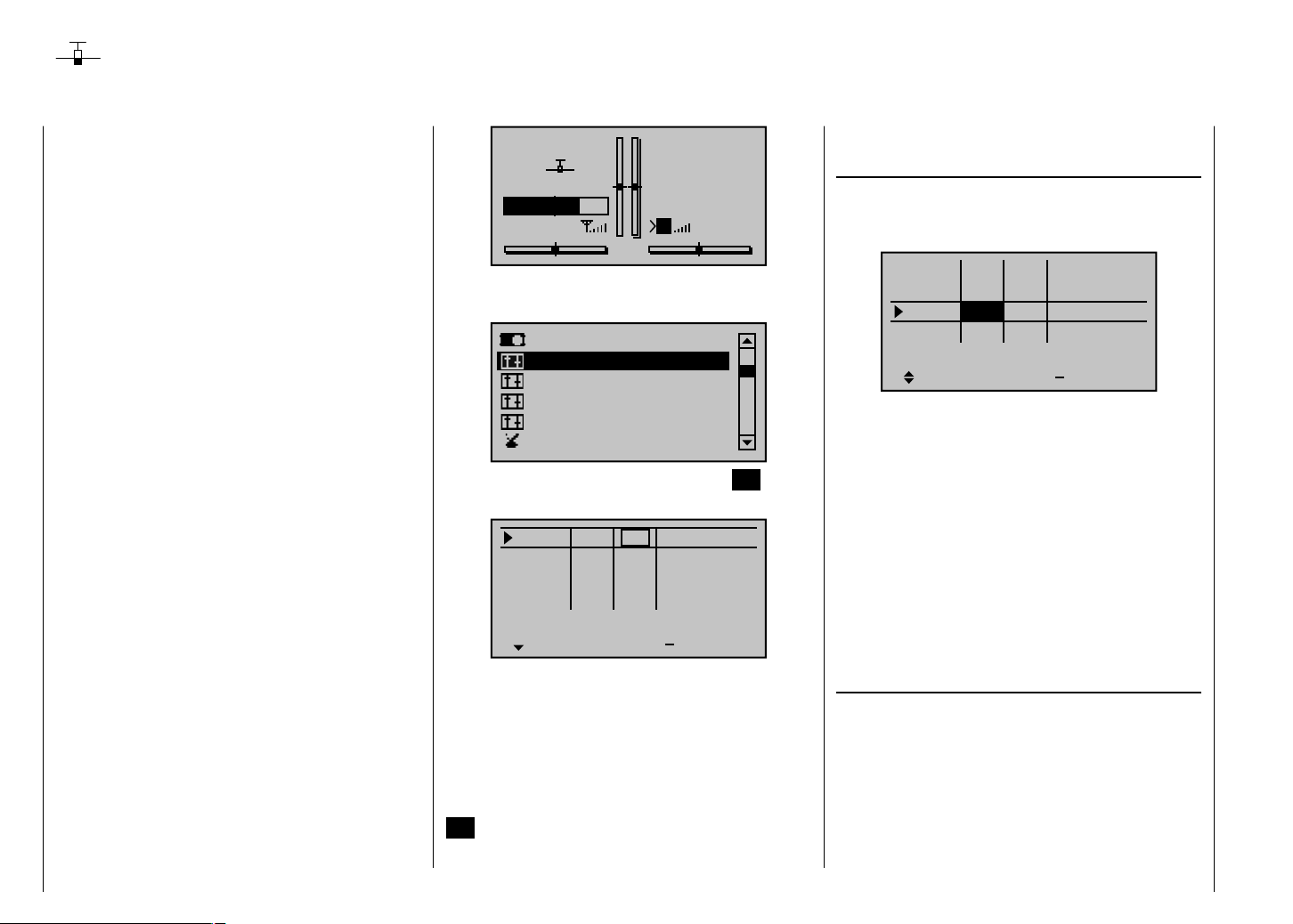
Joystick setting
Setting stick mode 1 through 4
Both joysticks are equipped for digital trimming. With
each brief push (one "click") on a joystick it will change
its neutral position by one increment. Holding the stick
longer will cause trimming to run in the corresponding
direction at increasing speed.
The current position is shown on the screen and
adjustment is also made "audible" by various high
frequency tones. This makes fi nding the mid-point during
fl ight easy, without looking at the screen. If the mid-point
is overrun, a brief motion pause will be inserted.
Current trim values are automatically stored when a
model memory change is made.
Furthermore – except for trimming the throttle/brake
joystick, commonly referred to as control function "C1"
(channel 1) – digital trimming is effective within a model
memory location selectively as either a global parameter
(i. e. consistent in all fl ight phases) or as a fl ight-phase
specifi c parameter. This specifi cation as "global"
or "phase" is made in the "Joystick setting" menu
described here, whereas C1 trimming is always made
"globally", i. e. independent of fl ight phases.
This setting is visualized in the base screen by a
"shadow" on trim bars:
shadow present = global,•
no shadow = fl ight phase dependent.•
The following fi gure shows elevator trim – in the right
column with standard Mode 1 – as being fl ight-phase
dependent.
Detail program description - Joystick setting
92
0.0s
0.0s
0.0s
0.0s
time
0:00
0:00
HoTT
5.5V
0.0s
0.0s
0.0s
0.0s
+
GRAUBELE
#01
«Normal »
5.2V
2:22h
Scroll with the arrow keys of the left or right touch pad to
the "Stick mode" menu item of the multifunction menu.
Servo adjustment
Stick mode
Control adjust
Dual Rate / Expo
Channel 1 curve
Switch display
Open this menu item by pressing the center SET button
in the right touch pad.
Ch.1
Aile
Elev
Rudd
This menu, adapted for winged models, permits the trim
effects of the four digital trim levers to be established
and control functions 1 through 4 to be selectively
"decelerated".
The desired line can be reached by using the arrow
keys of the left or right touch pad. Once the appropriate
function fi eld has been selected and then the center
SET button in the right touch pad is pressed briefl y, the
fi eld will appear in inverse video and the desired setting
GL
GL
GL
GL
Tr
Stop
Flt
K78
M
4
4
4
4
St
can be made with the arrow keys of the right touch pad.
Column "Tr" (trim)
Except for "channel 1", this column can be used to
switchover trim effect from "GL(obal)" to "PH(ase)" and
vice versa. For example:
Ch.1
Aile
Elev
Rudd
"GL": The position of the respective trim lever
is effective for the given model "globally",
i.e. across any fl ight phases which may be
programmed for it, page126.
"PH": The position of the respective trim lever is
effective on a phase-specifi c basis and will
be automatically stored upon change of fl ight
phase so that the setting is again available
following a return to this fl ight phase.
Simultaneously pressing the or keys of the
right touch pad (CLEAR) switches the entry back to
"GL".
Column "St" (trim steps)
The four digital trim levers push the neutral point of the
respective joystick by one increment for each press
("click"). This is where the increment size (step) can be
adjusted for a given direction, whereby maximum trim
travel, independent of the selected number of trim steps,
is always about ±30 % of control travel.
After selecting column "St" (Steps) and then the desired
trim control with the arrow keys of the left or right
GL
GL
PH
GL
Tr
St
4
4
4
4
0.0s
0.0s
0.0s
0.0s
time
0.0s
0.0s
0.0s
0.0s
+
Page 93

touch pad, the corresponding entry fi eld will be framed.
For example:
Ch.1
Aile
Elev
Rudd
Briefl y press the center SET button in the right touch
pad. The current setting will be displayed in inverse
video. Now select the desired value, between 1 and 10,
with the arrow keys of the right touch pad. For example:
GL
GL
GL
GL
Tr
St
4
4
4
4
0.0s
0.0s
0.0s
0.0s
time
0.0s
0.0s
0.0s
0.0s
+
sides or separate for each control direction. This setting
has a programmable range of 0 s to 9.9 s. In the case of
side-separate settings, the joystick is to be moved to the
respective side so that the inverse video fi eld will switch
between sides to the one for which the change is to be
made, – for example, even to ensure gentle rev-up of
the propulsion motor despite a (too) fast motion of the
C1 stick.
Ch.1
Aile
Elev
Rudd
GL
GL
GL
GL
4
4
4
4
0.0s
0.0s
0.0s
0.0s
1.1s
0.0s
0.0s
0.0s
Ch.1
Aile
Elev
Rudd
Simultaneously pressing the or arrow keys of
the right touch pad (CLEAR) will reset the change made
in the active fi eld back to "4".
Column "time"
The "time" column entries infl uence joystick acceleration
speed/s – if applicable, for each movement direction
for the four control sticks, 1 through 4, separately – .
This means that respective servos will then follow rapid
control position changes only at an accordingly delayed
rate. This time delay has a direct effect on the control
function and therefore also any servos controlled by this
function.
The time can be programmed symmetrically for both
GL
GL
GL
GL
Tr
St
4
4
8
4
0.0s
0.0s
0.0s
0.0s
time
0.0s
0.0s
0.0s
0.0s
+
St
Tr
On the other hand, for reasons of safety, the motor cutoff should always be "immediate".
Simultaneously pressing the or keys of the
right touch pad (CLEAR) will reset the change made to
the active fi eld back to "0.0 s".
time
+
Detail program description - Joystick setting
93
Page 94

Joystick setting
Setting stick mode 1 through 4
Both joysticks are equipped for digital trimming. With
each brief push (one "click") on a joystick it will change
its neutral position by one increment. Holding the stick
longer will cause trimming to run in the corresponding
direction at increasing speed.
The current position is shown on the screen and
adjustment is also made "audible" by various high
frequency tones. This makes fi nding the mid-point during
fl ight easy, without looking at the screen. If the mid-point
is overrun, a brief motion pause will be inserted.
Current trim values are automatically stored when a
model memory change is made.
Furthermore – except for trimming the throttle/brake
joystick – digital trimming is effective selectively either as
a global parameter, i. e. consistent in all fl ight phases, or
as a fl ight-phase specifi c parameter. This specifi cation
as "global" or "phase" is made in the "Joystick setting"
menu described here, whereas throttle trimming is
always made "global" by software, i. e. independent of
fl ight phases.
This setting is visualized in the base screen by a
"shadow" on trim bars:
shadow present = global,•
no shadow = fl ight phase dependent.•
In the following fi gure nick trimming is used as an
example of fl ight-phase dependence – presented in its
default Mode 1 at the left – .
STARLET
#02
«Normal »
5.2V
2:22h
Stop
Flt
K78
M
0:00
0:00
HoTT
5.5V
Scroll with the arrow keys of the left or right touch pad to
the " Stick mode " menu item of the multifunction menu.
Model select
Copy / Erase
Suppress menus
Suppress models
Base setup model
Model type
Open this menu item by pressing the center SET button
in the right touch pad.
Model select
Copy / Erase
Suppress models
Base setup model
Model type
Suppress: TOG
This menu, adapted for helicopter models, permits
the trim effects of the four digital trim levers to be
established and control functions 1 through 4 to be
selectively "decelerated".
The desired line can be reached by using the arrow
keys of the left or right touch pad. Once the appropriate
function fi eld has been selected and then the center
SET button in the right touch pad is pressed briefl y, the
fi eld will appear in inverse video and the desired setting
can be made with the arrow keys of the right touch pad.
Column "Tr" (trim)
These setting variations are confi gured to accommodate
the needs of helicopter models, which is why the following
alternative options are available for the "Thr." line:
Ch.1
Aile
Elev
Rudd
"TL": "throttle limit"
C1 trimming operates as idle trimming when
the "throttle limit" function regulates the motor
for starting, see "Control adjust" menu,
page 104.
"AR": "autorotation throttle"
C1 trim operates as idle trim exclusively in the
"Autorot" fl ight phase.
This makes it possible to assign a principle
(fi xed) preset AR throttle position in the
"Helicopter mixer" menu, page 164, e. g. for
use during autorotation practice, which can be
"varied" with the idle trim lever.
Simultaneously pressing the or
keys of the right touch pad (CLEAR) will
switch this option back to "TL".
On the other hand, the trim effects of respective digital
trimming controls for the lines "Roll", "Nick" and "Tail
rotor" can be switched over from "GL" to "PH" and vice
versa. Example:
Thr.
Roll
Nick
Tail
GL
GL
PH
GL
TL
GL
GL
PH
Tr
Tr
St
4
4
4
4
St
4
0.0s
4
0.0s
4
0.0s
0.0s
4
0.0s
0.0s
0.0s
0.0s
time
time
0.0s
0.0s
0.0s
0.0s
+
0.0s
0.0s
0.0s
0.0s
+
Detail program description - Joystick setting | Helicopter model
94
Page 95

"GL": The position of the respective trim lever
is effective for the given model "globally",
i.e. across any fl ight phases which may be
programmed for it, page 126.
"PH": The position of the respective trim lever is
effective on a phase-specifi c basis and will
be automatically stored upon change of fl ight
phase so that the setting is again available
following a return to this fl ight phase.
Simultaneously pressing the or keys of the
right touch pad (CLEAR) will switch the entry back to
"GL".
Column "St" (trim steps)
The four digital trim levers push the neutral point of the
respective joystick by one increment for each press
("click"). This is where the increment size (step) can be
adjusted for a given direction, whereby maximum trim
travel, independent of the selected number of trim steps,
is always about ±30 % of control travel.
After selecting column "St" (Steps) and then the desired
trim control with the arrow keys of the left or right
touch pad, the corresponding entry fi eld will be framed.
Example:
4
Thr.
Roll
Nick
Tail
Briefl y press the center SET button in the right touch
pad. The current setting will be displayed in inverse
video. Now select the desired value, between 1 and 10,
TL
GL
GL
PH
Tr
St
0.0s
0.0s
4
4
4
0.0s
0.0s
0.0s
time
0.0s
0.0s
0.0s
+
with the arrow keys of the right touch pad. For example:
Tr
St
4
4
8
4
0.0s
0.0s
0.0s
0.0s
time
0.0s
0.0s
0.0s
0.0s
+
Thr.
Roll
Nick
Tail
Simultaneously pressing the or keys of the
right touch pad (CLEAR) will reset any change made to
the active fi eld back to "4".
Column "time"
The "time" column entries infl uence joystick acceleration
speed/s – if applicable, for each movement direction
for the four control sticks, 1 through 4, separately – .
This means that respective servos will then follow rapid
control position changes only at an accordingly delayed
rate. This time delay has a direct effect on the control
signal and therefore also commensurately on any servos
controlled by the effected controls.
The time can be programmed symmetrically for both
sides or separate for each control direction. This setting
has a programmable range of 0 s to 9.9 s. In this latter
case, the given stick control is to be moved to the
respective side so that the inverse video fi eld will switch
between sides to the one for which the change is to be
made.
Example:
All three servos are to be actuated for swashplate
pitch control, e g. a "Pitch" control movement for a "3Sv
(2Roll)" swashplate. However, travel for the middle
servo is greater than that of the other two servos on the
shorter lever.
TL
GL
GL
PH
A rash "Pitch" control movement would not operate
the nick servo in the middle as quickly as it would the
two roll servos on the shorter lever. This would cause
a momentary control motion in the "nick" direction.
However, if response time for the "pitch" control function
were to be reduced by at least the positioning time for
the servo in the middle then all three servos would reach
their proper positions at the same time. The necessary
delay times typically amount to only a few tenths of a
second. For example:
Thr.
Roll
Nick
Tail
Simultaneously pressing the or keys of the
right touch pad (CLEAR) will reset any change made to
the active fi eld back to "0.0 s".
TA
GL
GL
PH
Tr
St
4
4
8
4
0.2s
0.0s
0.0s
0.0s
time
0.2s
0.0s
0.0s
0.0s
+
Detail program description - Joystick setting | Helicopter model
95
Page 96

Control adjust
Fundamental operating steps for control and switch assignments
Servo adjustment
Stick mode
Control adjust
Dual Rate / Expo
Channel 1 curve
Switch display
Briefl y press the center SET button in the right touch
pad.
Input 5
Input 6
Input 7
Input 8
normal
Aside from the two joysticks which operate control
functions 1 through 4, a standard mx-20 HoTT
transmitter is also equipped with other operating
elements:
two 3 position switches: SW 4/5 or CTRL 9 and SW •
6/7 or CTRL 10. These are assigned in this menu as
"Ct9" and "C10".
three proportional rotary controls: CTRL 6, 7 and 8. •
Respectively designated "Ct6", "Ct7" and "Ct8" in the
menu.
three 2 position switches: SW 2, 3 and 8. •
Respectively displayed in the menu as "2", "3" and
"8" in combination with a switch symbol indicating the
switching direction.
two pushbutton switches: SW 1 and SW 9. Analogous •
to the aforementioned switches; designated as "1"
and "9" and displayed in combination with a symbol
indicating switching direction.
GL
GL
GL
GL
typ
–––
–––
–––
–––
0%
0%
0%
0%
offset
In contrast to the two joysticks which, when initialized
for a new model memory as a "Winged aircraft" model
type will already be confi gured to operate the servos
connected to receiver outputs 1 … 4, these "other"
operating elements initially remain inactive.
Thus, at least in the system's delivered state, – as
already mentioned on page 20 – or even after the
initialization of a new model memory with the "Winged
aircraft" model type and its "binding" to the intended
receiver, only those servos connected to the two
joysticks by way of receiver outputs 1 … 4 are able to
be operated; any servos which may be connected to the
receiver's outputs 5 … 12 will initially remain inactive in
their middle positions.
Even though this may seem inconvenient at fi rst glance,
it is indeed just this state which offers full freedom to
select and assign these "other" operating elements as
desired and leaves any unused operating elements
harmlessly dormant without taking any action to
deactivate them. This has the advantage that:
An unused operating element will have no infl uence
on your model's operation even if inadvertently
operated; it will be inactive and therefore have no
assigned function.
These "other" operating elements can be freely
assigned to meet your needs and the features of your
model. They can be assigned to any function input in
the "Control adjust" menu, see page 50. But this also
means that each of these operating elements can also
be assigned to multiple functions at the same time.
For example, one and the same toggle switch, SW
X, assigned in this menu to an input, can at the same
time be assigned to a "timer" as an On/Off switch in the
"Timers (general)" menu...
Furthermore, all inputs can be selectively made global
or fl ight-phase specifi c (providing that fl ight phases have
been defi ned in the menus "Phase settings", page 128,
and "Phase assignment", page 134). The respective
names for the given fl ight phases will then appear in the
bottom screen line, e. g. "normal".
Basic procedure steps
Select the desired input, E5 ... 12 with the 1. arrow
keys of the left or right touch pad.
If necessary, use the 2. arrow keys of the left or
right touch pad to change to the desired column.
Briefl y 3. press the center
pad. The respective entry fi eld will be displayed in
inverse video.
Actuate the desired operating element or use the 4.
arrow keys of the right touch pad to set the desired
value.
Briefl y5. press the center SET button in the right touch
pad to complete the entry.
Simultaneously 6. pressing the or arrow
keys of the right touch pad (CLEAR) will reset any
setting change back to its default value.
SET button in the right touch
Detail program description - Control adjust
96
Page 97

Column 2 "typ"
Analogous to the "Stick mode" menu already described,
this column can be used to select whether other settings
are to be made for the given input, e. g. "GL(obal)" or
"PH(ase specifi c)" and vice versa.
Input 5
Input 6
Input 7
Input 8
normal
"GL": The given input's settings will be "globally"
effective for the respective model memory
across any fl ight phases which may be
programmed.
"PH": The settings for this input will be effective on
a fl ight-phase basis and must therefore be
explicitly set in each fl ight-phase where it is to
be effective.
Notice:
More about fl ight phases on page 126.
Column 3 "Control or switch assignment"
Use the arrow keys of the left or right touch pad to
select one of the inputs, 5 through 12.
Briefl y press the center SET button in the right touch
pad to activate the assignment.
GL
GL
GL
GL
typ
–––
–––
–––
–––
0%
0%
0%
0%
offset
Input 5
Eing. 6
Move desired switch
Eing. 7
or control adj.
Input 8
Normal
Now activate the desired control (CTRL 6 through 10)
or selected switch (SW 1 through 3, or 8 or 9) - whereby
a proportional rotary control will only be detected after
some "detenting" action has taken place and so may
have to be activated a bit longer. If adjustment travel is
insuffi cient, activate the control in the other direction.
Two position switches can only switch back and forth
between their fi xed end states, e. g. motor ON or OFF.
On the other hand, the 3 position switches, SW 4/5 or
6/7, that can be incorporated in this "Control adjust"
menu as "Ct9" or "C10", also offer a middle position.
Simultaneously pressing the or keys of the
right touch pad (CLEAR) for an active control or switch
assignment – see fi gure above – will reset the input back
to its "free" state.
Tips:
When assigning switches, pay attention to the •
desired switching direction and also that all unused
inputs remain "free" or are again reset to "free" (if
applicable, across all fl ight phases). This is necessary
to ensure that inadvertent actuations of these unused
controls cannot cause malfunctions.
The travel setting described below allows the •
appropriate end state to be established for an
assigned switch.
For example, the screen will now show either the
GL
GL
GL
GL
typ
–––
–––
–––
–––
0%
0%
0%
0%
offset
control's number or – in conjunction with a switch
symbol indicating the switching direction – the switch's
number .
Input 5
Input 6
Input 7
Input 8
Normal
Column 4 "offset"
The control midpoint for the given control, i. e. its zero
point, can be changed in this column. The adjustment
range lies between -125 % and +125 %.
Input 5
Input 6
Input 7
Input 8
Normal
Simultaneously pressing the or keys in
the right touch pad (CLEAR) will reset the entry fi eld
displayed in inverse video back to "0 %".
Column 5 "-travel+"
This column is used to set servo travel symmetrically or
asymmetrically for each side. The setting range is ±125 %
of normal servo travel.
Use the arrow keys of the left or right touch pad to
select one of the inputs, 5 through 12.
To set symmetric travel, i. e. control-side independent
travel, the respective operating element (proportional
rotary control or switch) is to be put into a position which
Detail program description - Control adjust
GL
GL
GL
GL
typ
GL
GL
GL
GL
typ
–––
3
Ct6
–––
–––
3
Ct6
–––
0%
0%
0%
0%
offset
0%
0%
0%
0%
offset
97
Page 98

covers travel to both sides of the marked frame.
Input 5
Input 6
Input 7
Input 8
Normal
To set asymmetric travel, the respective control
(proportional rotary control or switch) is to be moved to
the side on which the marked frame only includes the
value to be changed.
Input 5
Input 6
Input 7
Input 8
Normal
The value setting is activated by briefl y pressing the
center SET button in the right touch pad. The value
fi eld will be displayed in inverse video. Values can be
changed with the arrow keys of the right touch pad.
Input 5
Input 6
Input 7
Input 8
Normal
+100%
+100%
+100%
+100%
–travel+
+100%
+100%
+100%
+100%
–travel+
+100%
+100%
+100%
–travel+
+100%
+100%
+100%
+100%
+100%
+100%
+100%
+100%
+100%
+100%
+111%+111%
+100%
Input 5
Input 6
Input 7
Input 8
Normal
Another brief press of the center SET button in the right
touch pad will complete the entry.
Negative and positive parameter values are possible in
order to appropriately adapt the control's direction or
effect.
Simultaneously pressing the or keys in
the right touch pad (CLEAR) will reset the changes
parameter in the inverse video entry fi eld back to
+100 %.
Important:
In contrast to the servo travel setting, control travel
setting effects all derived mixer and coupling functions,
i. e. infl uences all servos which can be actuated by way
of the respective control.
Column 6 "time"
A symmetric or asymmetric time delay between 0 and
9.9 s can be applied to each of the 5 ... 12 function
inputs.
Use the arrow keys in the left or right touch pad to
push the marker frame to the right, beyond the "-travel+"
column.
To set a symmetric, (i. e. control-side independent) time
delay, the respective operating element (proportional
rotary control or switch) must be put into a position
which covers time to both sides of the marked frame.
+100%
+100%
+100%
–travel+
+100%
+100%
+88%+111%
+100%
Input 5
Input 6
Input 7
Input 8
Normal
To set an asymmetric time delay, the respective control
(proportional rotary control or switch) is to be moved to
the side on which the marked frame only includes the
value to be changed.
Input 5
Input 6
Input 7
Input 8
Normal
Notice:
Further suggestions for structuring timed fl ows can be
found in the section "Control of timed fl ows" on page 266.
0.0
0.0
0.0
0.0
– time +
0.0
0.0
0.0
0.0
– time +
0.0
0.0
0.0
0.0
0.0
0.0
0.0
0.0
Detail program description - Control adjust
98
Page 99

Detail program description - Control adjust
99
Page 100

Control adjust
Basic procedure for transmitter control and switch assignment
Servo adjustment
Stick mode
Control adjust
Dual Rate / Expo
Channel 1 curve
Switch display
Briefl y tap the center SET key on the right touch pad:
Input 5
Throt
Gyro
Input 8
Input 9
Input10
Input11
Th.L.12
In addition to the two dual axis sticks for control
functions 1 to 4, the mx-20 HoTT transmitter is
equipped with other controls as standard:
Two 3-stage switches: SW 4/5 and CTRL 9, plus SW •
6/7 and CTRL 10. On this menu, these are assigned
as "Ct9" and "Ct10".
Three proportional rotary controls: CTRL 6, 7 and 8. •
Named as "Ct6", "Ct7" and "Ct8" on this menu.
Three 2-stage switches: SW 2, 3 and 8. Labeled •
accordingly as "2", "3" and "8" on the menu. A switch
icon indicating the switch direction is also shown.
Two push-button switches: SW 1 and SW 9. •
Displayed as with the preceding switches, "1" and "9"
with a switch icon indicating the switch direction.
Even with a newly-initialized model memory for the
GL
–––
6
7
GL
GL
GL
GL
GL
GL
GL
typ
–––
–––
–––
–––
–––
–––
Ct6
0%
0%
0%
0%
0%
0%
0%
0%
offset
"Helicopter" model type, the two dual axis sticks will – in
the absence of further confi guration – infl uence only
those servos connected to receiver outputs 1 … 4 and
6. Unlike these, the "additional" transmitter controls
mentioned above are theoretically inactive at fi rst. (The
exception here is the CTRL 6 proportional rotary control
(throttle limiter), which also affects servo 6.)
One of the effects of this is that (as mentioned back
on page 20 ) with a factory-fresh unit, only the servos
connected to receiver outputs 1 … 4 and –depending on
the position of the throttle limiter– servo 6 can be moved
using the two joysticks. (This also applies following
the initialization of a new model memory with the
"Helicopter" model type and its "binding" to the receivers
to be installed in the model.) The servos connected
to slots 5, 7 and 8, on the other hand, will simply stay
"stuck" at their center points.
While this may appear more than a little awkward at
fi rst glance … this is the only way to ensure that you
can select any of the "additional" transmitter controls
as you wish and, in addition, do not need to waste time
"disabling" control elements you do not require. This is
because
the only way to ensure an unwanted control element
has no effect on your model, even if operated by
accident, is to make it inactive, i.e. unassigned to a
function.
You can therefore use this "Control adjust" menu
exactly as you wish, to assign the "additional" control
elements as you want to any required function input; for
further details, see page 50. Equally, this also means
that you can assign individual transmitter controls to
multiple functions at the same time, if required. As an
example: the exact same rocker switch SW X that you
assign to an input on this menu can simultaneously be
assigned to "Timers" on the "Timers (general)" menu
as an "On/Off" switch, etc.
Note:
As a rule, input 6 must kept "free" for a helicopter model.
On this, see "Throttle" on the next double page.
Furthermore, if fl ight phases have been defi ned on
the "Phase settings" menu (page 128) and "Phase
assignment" menu (page 134), then all inputs must be
set either as global or fl ight phase-specifi c. The names
assigned to each of these fl ight phases are then shown
in the bottom line of the screen display, e. g. "Normal".
Basic procedure
Using the arrow keys 1. on the left or right touch
pad, select the input you want: Input 5, Throt 6, Gyro
7, Input 8 … 11 or Th.L.12.
If necessary, use the arrow keys 2. on the left or
right touch pad to select the column you want.
Briefl y tap the center 3.
The corresponding input fi eld is shown highlighted.
Activate your chosen transmitter control or use 4. the
arrow keys on the right touch pad to set your chosen
value.
Briefl y tap the center 5. SET key on the right touch pad
to complete data entry.
If you 6. tap the or keys on the right touch
pad at the same time (CLEAR), this will reset any
settings made back to their respective default values.
Column 2, "typ"
Similarly to the "Stick mode" menu described
previously, this column can be used to defi ne whether
further settings for the input in question are to have a
SET key on the right touch pad.
Detail program description - Control adjust
100
 Loading...