

Page 1

1
Page 2

Contents
General Notes
Safety notes ................................................................... 3
Foreword ........................................................................6
Description of radio control system ...............................7
Power supply ............................................................... 10
Adjusting stick length ...................................................12
Opening the transmitter case ......................................12
Changing the stick mode ............................................. 13
Description of transmitter ............................................ 14
DSC (Direct Servo Control) .................................... 15
LCD screen ............................................................. 18
Operating buttons, function fi elds ...........................19
Channel selection, transmitter ..................................... 20
Adjusting screen contrast ............................................21
Channel selection, receiver .........................................22
Installation notes .......................................................... 23
Defi nition of terms ....................................................... 24
Assigning switches and transmitter controls ................ 25
Digital trims ..................................................................26
Position display, INC / DEC buttons .............................27
Servo display ............................................................... 27
Fixed-wing model aircraft ............................................28
Receiver socket assignment .............................. 29/30
Model helicopters ........................................................32
Receiver socket assignment ................................... 33
Program description
Reserving a new memory ............................................34
»Model memories« .................................................... 36
»Base settings« (model)
Fixed-wing model aircraft .......................................38
Model helicopter .....................................................42
»Servo settings« ........................................................ 48
»Control settings«
Fixed-wing model aircraft .......................................50
Model helicopter .....................................................52
Throttle limit function .........................................54
Contents
2
»Dual Rate / Expo«
Fixed-wing model aircraft .......................................56
Model helicopter .....................................................58
»Phase Trim« (fi xed-wing model aircraft) ....................60
What is a mixer? ..........................................................61
»Wing mixers« ........................................................... 61
»Heli mixer« ...............................................................66
Adjusting the throttle and collective pitch curve ...... 70
Autorotation settings ...............................................74
General notes regarding freely programmable mixers 76
»Free mixers« ............................................................77
Examples ................................................................80
»Swashplate mixers« ................................................ 81
»Fail-Safe« (SPCM modulation only) .......................... 82
Programming examples
Introduction .................................................................. 84
Fixed-wing model aircraft
First steps in programming a new model ................ 86
Including an electric power system ......................... 90
E-motor and butterfl y (crow) with the C1 stick ........ 92
Operating the timers ............................................... 94
Using fl ight phases .................................................95
Servos running in parallel ....................................... 96
Model deltas and fl ying wings ......................................97
F3A-models ............................................................... 100
Model helicopters ......................................................104
Trainer (teacher / pupil) systems ...............................110
Appendix
Trainer operations with the mx-16s ............................ 111
Approved frequencies ................................................ 113
Approval certifi cate / Conformity declaration .............114
Guarantee certifi cate ................................................. 115
The sole purpose of this manual is to provide information; it is subject to amendment without prior notifi cation.
The GRAUPNER company accepts no responsibility or
liability for errors or inaccuracies which may be found in
the information section of this manual.
Environmental protection
This symbol on the product, in the operating instructions or the packaging indicates that the product must
not be discarded via the normal household refuse at the
end of its useful life. Instead it must be taken to a collection point for the recycling of electrical and electronic apparatus.
The materials can be re-used according to their identifi cation code. You can make an important contribution to
the protection of our shared environment by recycling
old equipment and making use of its basic materials.
Dry and rechargeable batteries must be removed from
the device and taken to the appropriate collection point.
Please ask your local authority for the location of your nearest waste disposal site.
Page 3

Safety notes
Please read carefully!
We all want you to have many hours of pleasure in our
mutual hobby of modelling, and safety is an important
aspect of this. It is absolutely essential that you read
right through these instructions and take careful note of
all our safety recommendations.
If you are a beginner to the world of radio-controlled model aircraft, boats and cars, we strongly advise that you
seek out an experienced modeller in your fi eld and ask
him or her for help and advice.
If you ever dispose of this transmitter, these instructions
must be handed on to the new owner.
Application
This radio control system may only be used for the purpose for which the manufacturer intended it, i.e. for operating radio-controlled models which do not carry humans. No other type of use is approved or permissible.
Safety notes
SAFETY IS NO ACCIDENT
and …
RADIO-CONTROLLED MODELS ARE NOT
PLAYTHINGS
Even small models can cause serious personal injury and damage to property if they are handled incompetently.
Technical problems in electrical and mechanical systems can cause motors to rev up or burst into life unexpectedly, with the result that parts may fl y off at great
speed, causing considerable injury.
Short-circuits of all kinds must be avoided at all times.
Short-circuits can easily destroy parts of the radio control system, but even more dangerous is the acute risk of
fi re and explosion, depending on the circumstances and
the energy content of the batteries.
Aircraft and boat propellers, helicopter rotors, open gearboxes and all other rotating parts which are driven by
a motor or engine represent a constant injury hazard.
Do not touch these items with any object or part of your
body. Remember that a propeller spinning at high speed
can easily slice off a fi nger! Ensure that no other object
can make contact with the driven components.
Never stand in the primary danger zone, i.e. in the rotational plane of the propeller or other rotating parts, when
the motor is running or the drive battery is connected.
Please note that a glowplug engine or electric motor
could burst into life accidentally if the receiving system
is switched on when you are transmitting the transmitter.
To be on the safe side, disconnect the fueltank, or disconnect the fl ight battery.
Protect all electronic equipment from dust, dirt, damp,
and foreign bodies. Avoid subjecting the equipment to vibration and excessive heat or cold. Radio control equipment should only be used in “normal” ambient temperatures, i.e. within the range -15°C to +55°C.
Avoid subjecting the equipment to shock and pressure. Check the units at regular intervals for damage to cases and leads. Do not re-use any item which is damaged or has become wet, even after you have dried it out
thoroughly.
Use only those components and accessories which
we expressly recommend. Be sure to use only genuine
matching GRAUPNER connectors of the same design
with contacts of the same material. Use only genuine
GRAUPNER plug-in crystals on the appropriate frequency band – if your equipment still uses them.
Before you use the system, check that all connectors
are pushed home fi rmly. When disconnecting components, pull on the connectors themselves – not on the wires.
It is not permissible to carry out any modifi cations to
the RC system components. Avoid reverse polarity and
short-circuits of all kinds, as the equipment is not protec-
ted against such errors.
Installing the receiving system and deploying the receiver aerial
In a model aircraft the receiver must be packed in soft
foam and stowed behind a stout bulkhead, and in a model boat or car it should be protected effectively from
dust and spray.
The receiver must not make contact with the fuselage,
hull or chassis at any point, otherwise motor vibration
and landing shocks will be transmitted directly to it.
When installing the receiving system in a model with a
glowplug or petrol engine, be sure to install all the components in well-protected positions so that no exhaust
gas or oil residues can reach the units and get inside
them. This applies above all to the ON / OFF switch,
which is usually installed in the outer skin of the model.
Secure the receiver in such a way that the aerial, servo
leads and switch harness are not under any strain.
The receiver aerial is permanently attached to the receiver. It is about 100 cm long and must not be shortened
or extended. The aerial should be routed as far away as
possible from electric motors, servos, metal pushrods
and high-current cables. However, it is best not to deploy
the aerial in an exactly straight line, but to angle it: e.g.
run it straight to the tailplane, then leave the fi nal 10 - 15
cm trailing freely, as this avoids reception “blind spots”
when the model is in the air. If this is not possible, we recommend that you lay out part of the aerial wire in an Sshape inside the model, as close to the receiver if possible.
Installing the servos
Always install servos using the vibration-damping grommets supplied. The rubber grommets provide some degree of protection from mechanical shocks and severe vibration.
Safety notes
3
Page 4

Safety notes
Installing control linkages
The basic rule is that all linkages should be installed in
such a way that the pushrods move accurately, smoothly and freely. It is particularly important that all servo output arms can move to their full extent without fouling or
rubbing on anything, or being obstructed mechanically
at any point in their travel.
It is important that you should be able to stop your motor at any time. With a glow motor this is achieved by adjusting the throttle so that the barrel closes completely when you move the throttle stick and trim to their endpoints.
Ensure that no metal parts are able to rub against each
other, e.g. when controls are operated, when parts rotate, or when motor vibration affects the model. Metal-tometal contact causes electrical “noise” which can interfere with the correct working of the receiver.
Always extend the transmitter aerial fully before
operating your model.
Transmitter fi eld strength is at a minimum in an imaginary line extending straight out from the transmitter aerial. It is therefore fundamentally misguided to “point” the
transmitter aerial at the model with the intention of obtaining good reception.
When several radio control systems are in use on adjacent channels, the pilots should always stand together in
a loose group. Pilots who insist on standing away from
the group endanger their own models as well as those
of the other pilots.
Pre-fl ight checking
If there are several modellers at the site, check carefully
with all of them that you are the only one on “your” channel before you switch on your own transmitter. If two modellers switch on transmitters on the same channel, the
result is invariably interference to one or both models,
and the usual result is at least one wrecked model.
Safety notes
4
Before you switch on the receiver, ensure that the throttle stick is at the stop / idle end-point.
Always switch on the transmitter fi rst, and only then
the receiver.
Always switch off the receiver fi rst, and only then
the transmitter.
If you do not keep to this sequence, i.e. if the receiver
is at any time switched on when “its” transmitter is switched OFF, then the receiver is wide open to signals from
other transmitters and any interference, and may respond. The model could then carry out uncontrolled movements, which could easily result in personal injury or
damage to property. The servos may run to their endstops and damage the gearbox, linkage, control surface etc.
Please take particular care if your model is fi tted with a
mechanical gyro:
Before you switch your receiver off, disconnect the power supply to ensure that the motor cannot run up to
high speed accidentally.
As it runs down, the gyro can generate such a high
voltage that the receiver picks up apparently valid
throttle commands, and the motor could respond by
unexpectedly bursting into life.
Range checking
Before every session check that the system works properly in every respect, and has adequate range. This
means checking that all the control surfaces respond
correctly and in the appropriate direction to the transmitter commands at a suitable ground range. Repeat this
check with the motor running, while a friend holds the
model securely for you.
Operating your model aircraft, helicopter, boat or car
Never fl y directly over spectators or other pilots, and
take care at all times not to endanger people or animals.
Keep well clear of high-tension overhead cables. Never
operate your model boat close to locks and full-size vessels. Model cars should never be run on public streets or
motorways, footpaths, public squares etc..
Checking the transmitter and receiver batteries
It is essential to stop using the radio control system and
recharge the batteries well before they are completely
discharged. In the case of the transmitter this means –
at the very latest – when the message “Battery must be
charged” appears on the screen, and you hear an audible warning signal.
It is vital to check the state of the batteries at regular intervals – especially the receiver pack. When the battery is almost fl at you may notice the servos running more
slowly, but it is by no means safe to keep fl ying or running your model until this happens. Always replace or recharge the batteries in good time.
Keep to the battery manufacturer’s instructions and don’t
leave the batteries on charge for longer than stated. Do
not leave batteries on charge unsupervised.
Never attempt to recharge dry cells, as they may explode.
Rechargeable batteries should always be recharged before every session. When charging batteries it is important to avoid short-circuits. Do this by fi rst connecting the
banana plugs on the charge lead to the charger, taking
care to maintain correct polarity. Only then connect the
charge lead to the transmitter or receiver battery.
Disconnect all batteries and remove them from your model if you know you will not be using it in the near future.
Capacity and operating times
This rule applies to all forms of electrical power source:
battery capacity is reduced every time you charge the
pack. At low temperatures capacity is greatly reduced,
i.e. operating times are shorter in cold conditions.
Page 5

Frequent charging, and / or the use of maintenance programs, tends to cause a gradual reduction in battery capacity. We recommend that you check the capacity of all
your rechargeable batteries at least every six months,
and replace them if their performance has fallen off signifi cantly.
Use only genuine GRAUPNER rechargeable batteries!
Suppressing electric motors
All conventional electric motors produce sparks between
commutator and brushes to a greater or lesser extent,
depending on the motor type; the sparking generates
serious interference to the radio control system.
If an RC system is to work correctly, it is therefore important to suppress the electric motors, and in electricpowered models it is essential that every motor should
be effectively suppressed. Suppressor fi lters reliably eliminate such interference, and should always be fi tted
where possible.
Please read the notes and recommendations supplied
by the motor manufacturer.
Refer to the main GRAUPNER FS catalogue for more
information on suppressor fi lters.
Servo suppressor fi lter for extension leads
Order No. 1040
Servo suppressor fi lters are required if you are obliged
to use long servo extension leads, as they eliminate the
danger of de-tuning the receiver. The fi lter is connected
directly to the receiver input. In very diffi cult cases a second fi lter can be used, positioned close to the servo.
Using electronic speed controllers
The basic rule is that the electronic speed controller
must be chosen to suit the size of the electric motor it is
required to control.
There is always a danger of overloading and possibly
damaging the speed controller, but you can avoid this by
ensuring that the controller’s current-handling capacity is
at least half the motor’s maximum stall current.
Particular care is called for if you are using a “hot” (i.e.
upgrade) motor, as any low-turn motor (small number of
turns on the winding) can draw many times its nominal
current when stalled, and the high current will wreck the
speed controller.
Electrical ignition systems
Ignition systems for internal combustion engines can
also produce interference which has an adverse effect
on the working of the radio control system.
Electrical ignition systems should always be powered by
a separate battery – not the receiver battery.
Be sure to use effectively suppressed spark plugs and
plug caps, and shielded ignition leads.
Keep the receiving system an adequate distance away
from the ignition system.
Static charges
Lightning causes magnetic shock waves which can interfere with the operation of a radio control transmitter
even if the thunderstorm actually occurs several kilometres away.
Cease fl ying operations immediately if you notice an
electrical storm approaching. Static charges through
the transmitter aerial can be life-threatening!
Caution
Radio control systems may only be operated on the frequency bands and spot frequencies approved in each
EU country. You will fi nd information on frequencies in
the section entitled “Approved operating frequencies” on
page 113. It is prohibited to operate radio control systems on any other frequency, and such misuse will be
punished by the relevant authorities.
Care and maintenance
Don’t use cleaning agents, petrol, water or other solvents to clean this equipment. If the case, the aerial etc.
gets dirty, simply wipe the surfaces clean with a soft dry
cloth.
Components and accessories
As manufacturers, the company of GRAUPNER GmbH
& Co. KG recommends the exclusive use of components and accessories which have been tested by
GRAUPNER and approved for their capability, function
and safety. If you observe this rule, GRAUPNER accepts
responsibility for the product.
GRAUPNER cannot accept liability for non-approved
parts or accessories made by other manufacturers.
It is not possible for GRAUPNER to assess every in-
dividual item manufacture red by other producers,
so we are unable to state whether such parts can be
used without incurring a safety risk.
Liability exclusion / Compensation
We at GRAUPNER are unable to ensure that you ob-
serve the operating instructions, and are not in a position to infl uence the way you install, operate and maintain
the radio control system components. For this reason we
are obliged to refute all liability for loss, damage or costs
which are incurred due to the incompetent or incorrect
use and operation of our products, or which are connected with such operation in any way.
Unless otherwise prescribed by law, the obligation of the
GRAUPNER company to pay compensation is limited
to the invoice value of that quantity of GRAUPNER pro-
ducts which was immediately and directly involved in the
event in which the damage occurred. This does not apply if GRAUPNER is found to be subject to unlimited liability according to binding legal regulation on account of
deliberate or gross negligence.
Safety notes
5
Page 6

mx-16s – the latest generation of radio control technology
During the development phase of the mx-16s we retained and further refi ned the overall programming philosophy of the mc-24. This system was introduced in 1997
and is renowned throughout the world; many thousands
are already in use.
Although this radio control system has been specially
developed for the beginner, it is capable of controlling all
current types of model, from fi xed-wing model aeroplanes and helicopters to model boats and cars.
In the area of fi xed-wing models and helicopters it is often necessary to employ complex mixer functions for the
control surfaces or the swashplate control system. Computer technology enables you to activate a vast range of
functions to cope with special model requirements – just
by pressing a button. With the mx-16s all you do is select the appropriate model type, and the software then
presents you automatically with the appropriate mixer
and coupling functions. This means that the transmitter requires no additional modules in order to implement
complex coupled functions, and you can forget all about
old-fashioned mechanical mixers in the model. The mx16s provides an extremely high level of safety and reliability in use.
The software is carefully arranged in a logically structured menu system. Options which are inter-connected in
terms of function are clearly organised in terms of content.
• Model memories
• Base settings
• Servo settings
• Control settings
• Dual Rate/Expo
• Phase trim (fi xed-wing only)
• Wing mixers / Heli mixer
• Free mixers
Introduction
6
• Swashplate mixers (helicopter only)
• Fail Safe (SPCM transmission mode only)
The mx-16s provides 12 model memories, each of
which can store model settings for different fl ight phases. Individual phases can be called up in fl ight simply by operating a switch, so that you can try out various
settings quickly and without risk. This can be for test purposes or for varying parameters for different phases of
fl ight.
The large graphic screen makes operating the transmitter a simple, self-explanatory process. Mixers and other
functions can be displayed in graphic form, and this is
extraordinarily helpful.
The beginner soon becomes familiar with the wide range of functions available thanks to the clear, logically arranged program structure. Adjustments are made
using just two rocker buttons, together with the SELECT
and CLEAR buttons to either side of the high-contrast
screen, and in this way you very quickly learn how to
make full use of all the options you need, depending on
your experience in handling radio-controlled models.
When used with the new “smc…” receivers the mx-16s
can provide servo travel at extremely high resolution
with 1024 control “steps” using the SUPER-PCM digital
modulation mode, for ultra-fi ne control. Naturally we guarantee full compatibility with earlier PPM-FM and PCM
receiver systems.
This manual describes each menu in detail, and also
provides dozens of useful tips, notes and programming
examples to complement the basic information. More
general modelling terms, such as Transmitter controls,
Dual-Rates, Butterfl y (Crow) and many others, are all
explained in the manual.
The appendix contains comprehensive information on
the Trainer (teacher / pupil) system. The manual concludes with a table of the frequencies approved for
use in individual European countries, copies of the Approval Certifi cate, the Conformity Declaration and the
transmitter’s Guarantee Certifi cate.
Please read the safety notes and the technical information. We recommend that you read right through the instructions with great care, and check all the functions
as described in the text. This can be carried out simply
by connecting servos to the supplied receiver, and watching their response as you program the transmitter.
This is the quickest method of becoming familiar with the
essential procedures and functions of the mx-16s.
Always handle your radio-controlled model with a responsible attitude to avoid endangering yourself and
others.
All of us in the GRAUPNER team wish you every success and many years of pleasure with your mx-16s,
which is an excellent example of the latest generation of
radio control systems.
Kirchheim-Teck, november 2006
Page 7
mx
-16s Computer System
Eight-channel digital proportional radio control system
High-technology micro-computer radio control system with new high-speed single-chip micro-computer, fl ash memory and 10-bit A/D converter
A computer radio control system with twelve model memories, carefully optimised and incorporating
top-level technology.
Modern computer system for unbeatable reliability.
Simplifi ed, straightforward programming technique
using rocker buttons and momentary buttons.
The high-contrast graphic screen provides an effi cient means of monitoring set-up parameters, operating modes, timers and battery voltage.
• Modern hardware and integrated Synthesizer system
for channel selection, with security menu to guard
against setting the wrong frequency accidentally
• Methods of operation and programming based on the
proven concepts of the mc-19 to mc-24
• Eight control functions with extremely convenient,
simplifi ed method of assigning controls for auxiliary
functions such as switches and proportional controls
• Unrestricted assignment of all switches to switched
functions simply by operating the desired switch
• Twelve model memories for storing all model-specifi c
programming and set-up parameters
• The latest back-up system requiring no Lithium battery
• Four switches (of which one is a three-position
switch), one momentary button, one analogue control, two digital controls installed as standard; freely
programmable for extreme flexibility
• Function encoder with two rocker buttons and two
momentary buttons for simplified programming and
accurate set-up
• Convenient mode selector provides simple method
of switching the stick mode (modes 1 - 4, e.g. throttle
right / throttle left). When you change modes, all the
affected settings are switched at the same time
• Graphical servo display provides a straightforward
overview of the servo set-up and a fast method of
checking servo travels
• Receiver output swap
• Wing menu for: 1AIL, 2AIL, 2AIL + 2FLAP, V-tail, delta / fl ying wing and two elevator servos
Wing mixer: AIL diff, FL diff, AIL RUD, AIL FL,
Brake ELE, Brake FL, Brake AIL, ELE
FL, ELE AIL, FL ELE, FL AIL and Diff. reduction
Description of radio control system
7
Page 8

• Heli menu: 1-point, 2-point, 3-point and 4-point linkages (1 SV, 2 SV, 3 SV (2 roll), 3 SV (2 nick), 4 SV
(90°))
• Two selectable modulations:
SPCM – Super PCM modulation with high system re-
solution of 1024 steps per control function. For the
following receivers: smc-14, smc-19, smc-20, smc19DS, smc-20DS, smc-16SCAN, smc-20DSYN, smc20DSCAN, R 330 S
PPM – The most widespread standard transmission
method (FM and FMsss). For the following receivers:
C12, C16, C17, R16SCAN, C19, DS18, DS19, DS20,
plus the following miniature receivers: XP4, XP10,
XP12FM, XP14, XN12, XM16, RB14 SCAN, R16
SCAN, R200 FM 40, R600, R600 light, R700 and C6,
C8, SB6 SYN 40S, SR6SYN
• Servo travel adjustment +/-150% for all servo channels, variable for each end-point separately (Single
Side Servo Throw)
• Sub-trim for fine-tuning the neutral position of all servos
• Servo reverse, programmable for all servos
• DUAL RATE/EXPO system, separately variable, can
be switched in-fl ight
• Mixer functions:
Aileron differential mixer, butterfly mixer, flaperon mi-
xer and three freely programmable mixers
• Convenient swashplate programs for model helicopters
• Programmable Fail-Safe function with hold-mode and
preset function (SPCM only)
• Stopwatch / count-down timer with alarm function
• Model memory copy function
• Integral DSC socket for use with flight simulators and
Trainer systems
Description of radio control system
8
Page 9

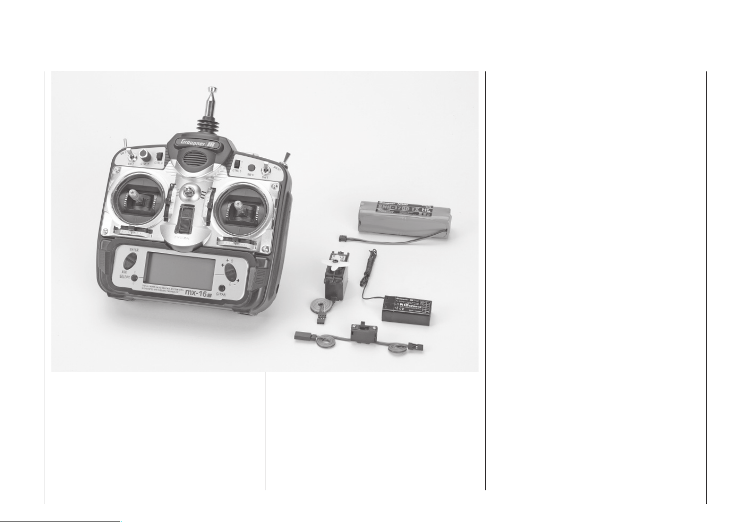
The sets contain:
mx-16s transmitter with Synthesizer transmitter module on the appropriate frequency band, integral 8NH-1700
mAh NiMH battery (type may differ), R16SCAN receiver
on the appropriate frequency, one C 577 servo, switch
harness.
Order No. 4701 35 MHz band (A- and B-band)
Order No. 4703 40/41 MHz band
Please refer to the table on page 113 for details of approved frequencies in individual EU countries.
Specifi cation of R16SCAN receiver
Operating voltage 4,8 ... 6 V
Current drain approx. 24 mA
Spot frequencies, 35 MHz 61 ... 282 / 182 ... 191*
Spot frequ., 40 / 41 MHz 50 ... 92 / 400 ... 420**
Channel spacing 10 kHz
Sensitivity approx. 10 µV
Modulation PPM
Servo functions 8
Temperature range -15° ... +55° C
Aerial length approx. 1000 mm
Dimensions approx. 46 x 25 x 15 mm
Weight approx. 17 g
* Channels 60, 281 and 282 not approved for use in Germany
** 41 MHz approved for use in France only
Specifi cation of mx-16s transmitter
Transmission system SPCM und PPM (FM / FMsss)
Synthesizer RF section 35 MHz A-band and B-band
40/41 MHz band
Please refer to the table on page 13 for details of approved frequencies in individual EU countries
Channel spacing, Synthesizer 10 kHz
Maximum control functions SPCM = 8, PPM = 8
Control functions 8 functions, 4 with trims
Channel pulse width 1,5 ms +/-0,5 ms
Temperature range -15 ... +55°C
Telescopic aerial 10-section, approx. 1150 mm long
Operating voltage 9,6 ... 12 V
Current drain approx. 225 mA (approx. 65 mA excl. RF)
Dimensions approx. 190 x 195 x 85 mm
Weight approx. 870 g incl. transmitter battery
Accessories
Order No. Description
1121 Neckstrap, 20 mm wide
70 Neckstrap, 30 mm wide
3097 Wind-shield for hand-held transmitter
See page 111 for mx-16s Trainer leads
Replacement part
Order No. Description
3100.6 Telescopic aerial for mx-16s transmitter
Description of radio control system
9
Page 10
Operating notes
Power supply
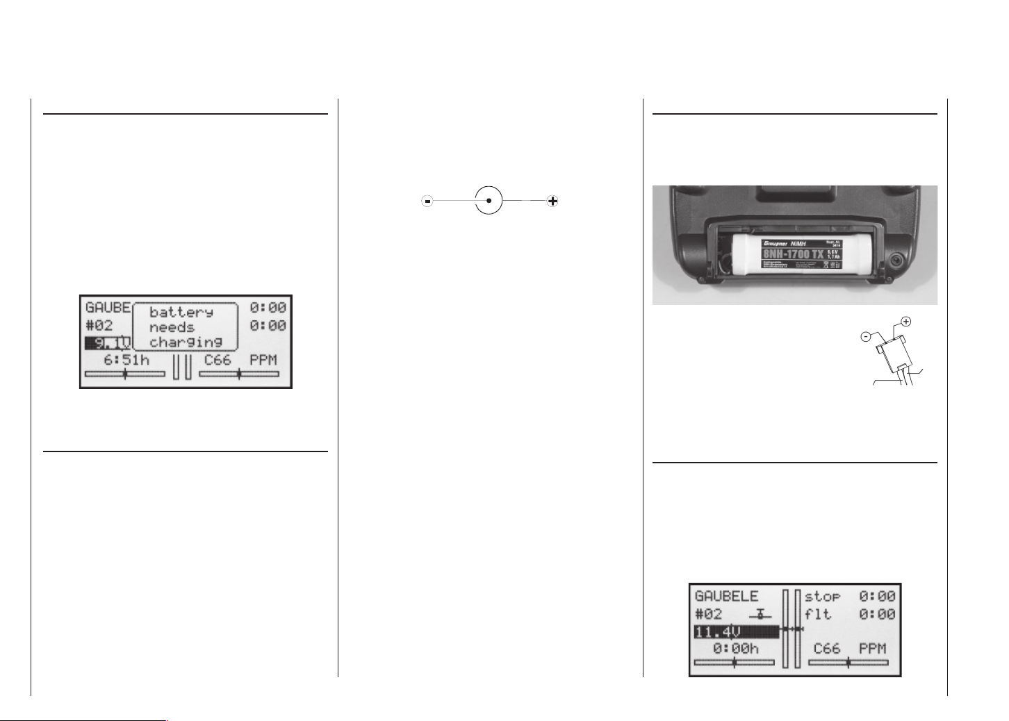
The battery compartment in the mx-16s transmitter is
designed to be fi tted with a high-capacity 8NH-1700 TX
9.6 V NiMH battery (Order No. 3414) (type may differ).
When delivered, the standard rechargeable battery
fi tted is not charged.
When you are using the transmitter you can monitor the
battery voltage on the LCD screen. If the voltage of the
transmitter battery falls below a certain point, you will
hear an audible warning signal. The screen then displays a message reminding you that the transmitter battery needs to be recharged.
When you see this message, cease operations immediately and recharge the transmitter battery.
Charging the transmitter battery
The rechargeable transmitter battery can be charged
via the charge socket fi tted to the right-hand side of the
case. Leave the battery inside the transmitter for charging, to avoid premature damage to the internal battery socket.
The transmitter must be switched “OFF” for the whole
period of the charge process. Never switch on the transmitter when it is still connected to the charger; even a
very brief interruption in the charge process can cause
the charge voltage to rise to the point where the transmitter is immediately damaged by the excess voltage.
For this reason check carefully that all connectors are
secure, and are making really good contact.
Polarity of the mx-16s charge socket
Commercially available battery charge leads produced
by other manufacturers are often made up with the opposite polarity. For this reason use genuine GRAUPNER
charge leads exclusively.
Charging the transmitter battery using an automatic
charger
The transmitter is designed as standard for use with automatic battery chargers. However, this requires care on
your part:
The transmitter charge socket is not protected
against short-circuit and / or reversed polarity. It
is therefore essential to use the correct procedure when connecting the charge lead: fi rst connect
the banana plugs on the charge lead to the charger,
and only then connect the other end of the lead to
the transmitter charge socket. When the charge lead
is connected to the transmitter, never allow the bare
ends of the plugs to touch!
Charging the transmitter battery using a standard
charger
It is also possible to charge the transmitter battery using
a charger with no automatic termination (cut-off) circuit.
The basic rule in this case is to charge the battery for
fourteen hours, assuming that it is initially fl at. The charge current should be one tenth of the capacity printed
on the battery. In the case of the standard transmitter
battery this means 170 mA. However, you are responsible for terminating the charge process manually if you
use a standard charger …
Removing the transmitter battery
The fi rst step in removing the transmitter battery is to
open the battery compartment cover in the back of the
case. This is accomplished by pushing it in the direction
of the arrow; it can then be lifted off:
Disconnect the plug at the end of
the transmitter battery lead by pulling carefully on the lead, or by engaging a fi nger nail behind the lug
on the top of the connector. However, don’t pull the plug down or up;
keep it as parallel as possible to the
surface of the transmitter.
brown or
black
Transmitter charge
plug polarity
Battery timer, bottom left corner of the screen
This timer displays the cumulative operating time of the
transmitter since the last time the transmitter battery
was charged.
This timer is automatically reset to “0:00” when the
transmitter detects that the voltage of the transmitter
battery is signifi cantly higher than the last time it was
switched on, e.g. as a result of a charge process.
red
Operating notes
10
Page 11

Receiver batteries
A wide variety of rechargeable 4.8 V NC and NiMH batteries is available. For safety reasons do not use a battery box, and never use dry cells.
There is no direct method of checking receiver battery
voltage when operating a model.
Make it a standard part of your routine to check the
state of your batteries at regular intervals. Don’t
wait until you notice the servos running more slowly
than usual before recharging the packs.
Note:
Please refer to the main GRAUPNER FS catalogue for
full details of batteries, chargers, measuring equipment
and monitor units for checking batteries.
Charging the receiver battery
The charge lead, Order No. 3021, can be connected directly to the NC receiver battery for charging. If the battery is installed in a model and you have installed one of
the following switch harnesses: Order No. 3046, 3934 or
3934.1 or 3934.3, the battery can be charged via the separate charge socket, or the charge socket which is built into the switch. The switch on the switch harness must
be left at the “OFF” position for charging.
General notes on battery charging
• Observe the recommendations provided by the charger manufacturer and the battery manufacturer at all
times. Observe the maximum permissible charge current stated by the battery manufacturer.
The maximum charge current for the transmitter bat-
tery is 1.5 A. Limit the charge current to this value on
the charger.
• Carry out a series of test charges to ensure that the
automatic charge termination circuit works correctly
with your battery.
This applies in particular if you are using an auto-
matic charger designed for NiCd batteries to recharge the standard NiMH battery.
You may need to adjust the Delta Peak trigger volta-
ge, if your charger provides this option.
• Do not discharge the battery or carry out a battery
maintenance program via the integral charge socket.
The charge socket is not suitable for this application.
• Always connect the charge lead to the charger fi rst,
and only then to the transmitter or receiver battery. Observing this rule eliminates the danger of accidental short-circuits between the bare contacts of the
charge lead plugs.
• Never leave batteries on charge unsupervised.
Standard chargers
Order No. 6422 Minilader 2
Order No. 6427 Multilader 3
Order No. 6426 Multilader 6E*
Order No. 6428 Turbomat 6 Plus*
Order No. 6429 Turbomat 7 Plus*
Automatic chargers with special NiMH charge programs
Order No. 6419 Ultramat 5* **
Order No. 6410 Ultramat 10*
Order No. 6412 Ultramat 12* **
Order No. 6414 Ultramat 14*
Order No. 6417 Ultramat 25* **
Order No. 6416 Ultra Duo Plus 30* **
* To recharge the mx-16s system you will also need the transmitter
charge lead, Order No. 3022, and the receiver battery charge lead,
Order No. 3021.
** 12 V power source required
Disposing of dry cells and rechargeable batteries
Never dispose of exhausted batteries in
the household rubbish. As end-user you
are legally required (by the “Battery Regulation”) to return old and exhausted
batteries. They should and must be taken to your local toxic waste collection
point so that the materials can be reused or re-cycled. They can also be returned to any retail outlet where batteries are sold.
Please contact your local authority if you are not sure
where your nearest battery recycling centre is located.
Operating notes
11
Page 12
Operating notes
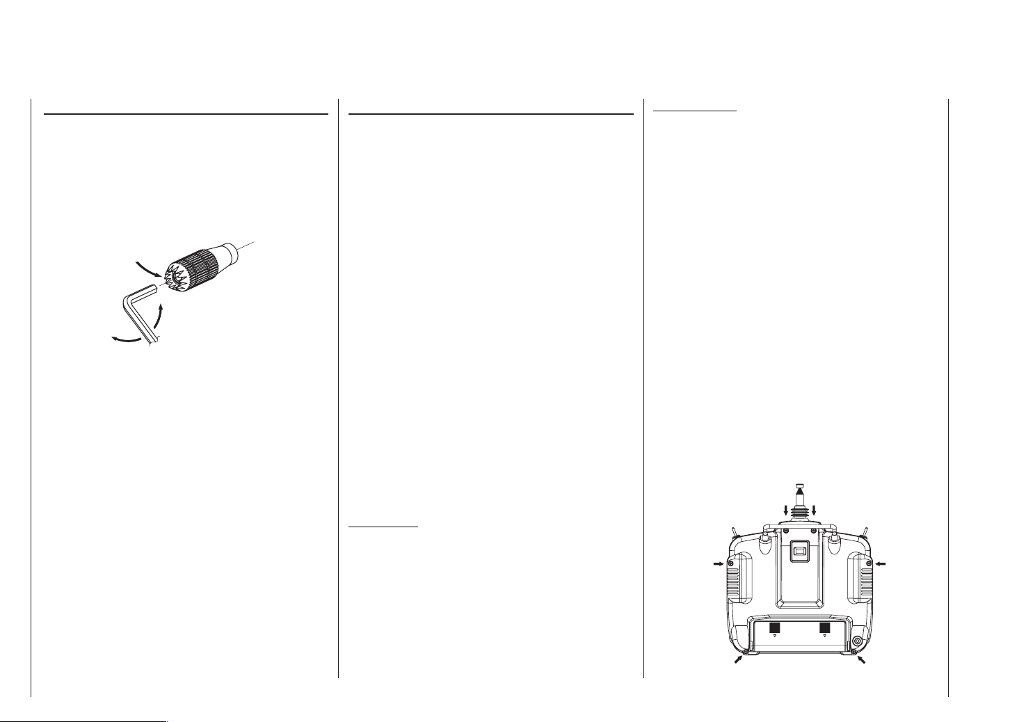
Adjusting stick length
Both sticks are infi nitely variable in length over a broad
range, enabling you to set them to suit your personal
preference to provide fi ne, accurate control.
Loosen the locking screw using a 2 mm allen key, then
screw the stick top in or out to shorten or extend it. Tighten the grubscrew again carefully to lock the set length.
Locking screw
Loosen
Tighten
Opening the transmitter case
Please read the following notes carefully before you
open the transmitter. If you have no experience in such
matters, we recommend that you ask your nearest
GRAUPNER Service Centre to carry out the work for
you.
The transmitter should only be opened in the following
cases:
• When a self-neutralising stick needs to be converted
to non-neutralising action, or a non-neutralising stick
to a self-neutralising action
• If you wish to adjust the stick centring spring tension
Before opening the transmitter check that it is switched
off (move Power switch to “OFF”).
There is no need to remove the transmitter battery. However, if you leave it in place be sure not to switch the
transmitter on (“ON” position). If you wish to remove the
transmitter battery, please read the section on page 10.
Locate the six recessed screws on the back on the
transmitter, and undo them using a PH1-size cross-point
screwdriver (see drawing right). Hold the two case sections together with your hand, and turn the unit over to
allow these six screws to fall out onto the table. Now carefully raise the case back and fold it open to the left, as
if you were opening a book.
C A U T I O N
A two-core lead connects the case back to the trans-
mitter electronics in the front section. Please take
great care not to damage this cable!
Important note:
• Do not modify the transmitter circuit in any way,
as this invalidates your guarantee and offi cial approval for the system.
• Do not touch any part of the circuit boards with
any metal object. Avoid touching the contacts
with your fi ngers.
• Never switch the transmitter on while the case is
open.
Please note the following points when closing the
transmitter:
• Make sure that no cables are jammed between the
transmitter case sections when you close the back.
• Ensure that the DSC socket engages in its mounting.
• Check that the two case sections fit together flush all
round before fitting the retaining screws. Never force
the two case components together.
• Fit the case screws in the existing threads, and tighten them gently. Over-tightening them will strip the
threads in the plastic.
Arrangement of the transmitter case screws
Operating notes
12
Page 13
Changing the stick mode
Either or both sticks can be converted from self-neutralising to non self-neutralising action: Start by opening the
transmitter as described on the previous page.
The procedure for changing the default stick mode setting is as follows:
1. Use a pair of tweezers to disconnect the spring from
the centring lever on the stick whose mode you wish
to change. If you are not sure, move the appropriate
stick to make it obvious. Raise the lever and disconnect it.
2. Locate the hexagonal bush supplied in the accessory pack, and
screw it into the hole. Now fi nd
the ratchet spring (also supplied)
and fi x it to the plastic pillar using
the black self-tapping screw
supplied. You can now set the
strength of the ratchet spring on
Brassbush
the side of the hexagonal bush by
screwing the M3 screw in or out.
3. Check that the stick works as you prefer, then close
the transmitter case once more.
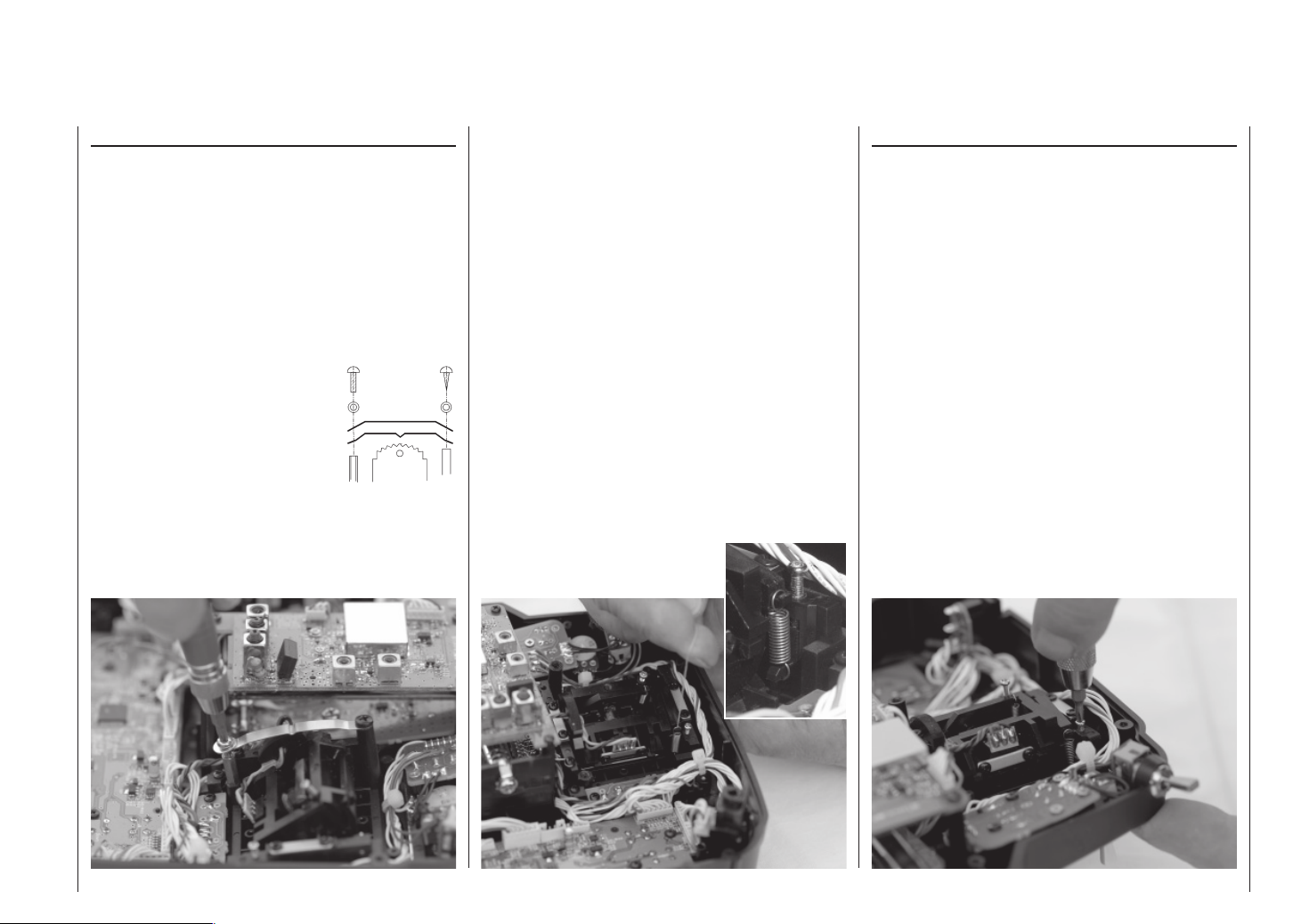
Resetting the spring to “self-neutralising” action
Open the transmitter as already described.
1. Disconnect and remove the ratchet spring: see picture left.
2. Now re-connect the (previously removed) centring spring to the side of the stick where the ratchet
spring was located.
3. First loosen the stick centring spring adjustor screw
slightly – see picture right – and then draw a length
of thin thread through the upper loop of the spring –
but don’t tie it. Now use a pair of tweezers to connect
the spring to the bottom loop of the adjustment system, and then engage the top end of the spring to the
centring lever using the thread. Once the spring is
correctly fi tted, the thread can be removed again.
4. The tension of the stick centring spring can be adjusted as described in the next section.
Stick centring spring tension
The stick centring force can be adjusted to suit the
pilot’s personal preference. The adjustment system is located adjacent to the stick centring spring. Rotate the
adjustor screw using a cross-point screwdriver until the
spring tension feels right to you:
• Turn to the right = harder spring tension;
• Turn to the left = softer spring tension.
Operating notes
13
Page 14
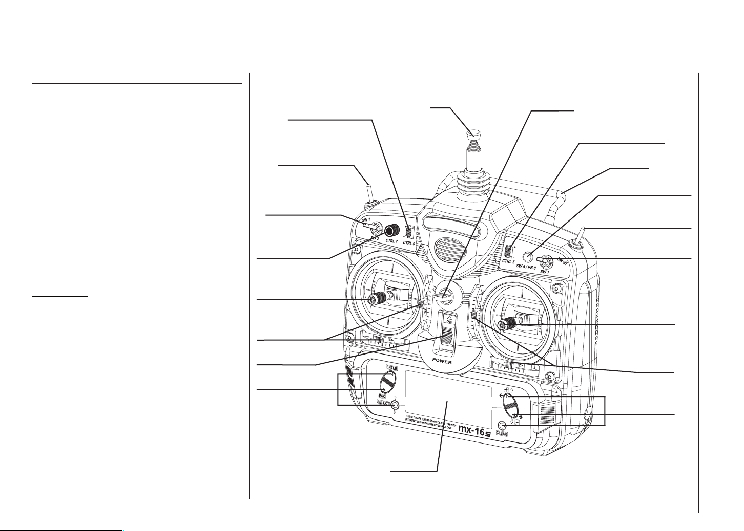
Description of transmitter
transmitter controls
Attaching the transmitter neckstrap
You will fi nd a strap lug mounted in the centre of the
front face of the mx-16s transmitter, as shown in the drawing on the right. This lug is positioned in such a way
that the transmitter is perfectly balanced even when suspended from a neckstrap.
1121 Neckstrap, 20 mm wide
70 Neckstrap, 30 mm wide
CTRL 6: INC / DEC buttons*
SW 3: two-position switch
SW 2: two-position switch
Aerial
Neckstrap lug
CTRL 5: INC / DEC buttons*
Carry handle
Button: SW 4 / PB 8
SW 6 / 7: three-position switch
Important note:
In the transmitter’s standard form any servos connected to the receiver can initially only be operated using
the dual-axis sticks. For maximum fl exibility, all the other
transmitter controls (CTRL 5 ... 7, SW 1 ... 7) are in software terms “free”, and can be assigned to any channels
you like, enabling you to set up the system to suit your
personal preference or the requirements of a particular model. This is carried out in the »Control settings«
menu, as described on pages 50 and 52.
* INC / DEC buttons (CTRL 5 and 6)
Each time you press the button the servo travel changes by 1% of
the set maximum; the system works as follows:
INC – in the positive direction;
DEC – in the negative direction.
Description of transmitter – transmitter controls
14
CTRL 7: rotary proportional control
Left-hand stick unit
Trims
ON / OFF switch
Input buttons
SW 1: two-position switch
Right-hand stick unit
Trims
Input buttons
LCD screen
Page 15
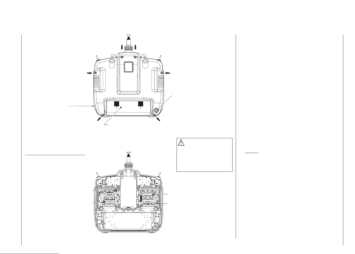
Transmitter case back
DSC
Direct Servo Control
Case screw
Transmitter battery charge socket
Case screw
Adjusting the centring spring force
Right vertical
Right horizontal
Case screw
Battery compartment cover
Case screw
mitter circuit board!
Do not touch the trans-
Do not touch the trans-
mitter circuit board!
Case screw
DSC socket for connection to fl ight simulators, Trainer lead and Diagnosis (closed
loop) lead (see right-hand column)
DSC = Direct Servo Control
Case screw
Caution
The battery lead is polarised,
i.e. it can only be plugged in
one way round. Don’t use force
when disconnecting the battery
connector!
Left horizontal
Left vertical
The original function of this socket was for “Direct Servo Control”, and that’s why the abbreviation is still in use.
However, it is now much more versatile than simply providing a means of controlling servos by cable. The DSC
socket is now also used as an interface for fl ight simulators, and for connecting a Pupil transmitter to a Teacher
transmitter to form a Trainer (buddy box) system.
For the DSC connection to work you must check the
following:
1. Carry out any adjustments required in the appropriate menus:
If you are connecting the transmitter to a fl ight simu-
lator (for example), these settings are found in the
»Modulation« line of the »Base settings« menu –
“PPM” is usually required.
If you are connecting a Diagnosis lead (Order No.
4178.1), the modulation must be selected to suit the
receiver – see below.
See page 110 for information on setting up the mx-
16s transmitter to work as part of a Trainer system.
2. Always leave the transmitter’s On / Off switch in the
“OFF” position, for only in this position is the RF section of the transmitter module switched off (no RF signal) even when the DSC lead is plugged in.
This is particularly important if you are using a Dia-
gnosis lead or a Trainer lead, otherwise you can still
cause interference to other pilots.
3. Connect the appropriate connecting lead to the DSC
socket on the back of the transmitter. This renders the
transmitter ready for use, circumventing the channel
section, and the LCD screen operates. At the same
time the letters “DSC” appear on the right-hand side
of the LCD screen, instead of the usual display of the
selected transmission channel.
4. Connect the other end of the connecting lead to the
desired apparatus, taking into account the operating
Description of transmitter – case back
15
Page 16

instructions supplied with that equipment.
If you wish to use the Diagnosis lead, Order No.
4178.1, do not connect it directly to the receiver. First
connect the lead to a receiver battery using a Y-lead,
and connect this to the receiver’s battery input socket
instead of the receiver battery. The end with the barrel plug can then be connected to the appropriate socket on the back of the transmitter.
Once the transmitter is connected to the receiver as
described above, you can check the control functions or make changes to settings even if another pilot is using “your” frequency. Since in this state (power = “OFF”) the transmitter does not broadcast a ra-
dio signal, you can, for example, prepare your model
ready to fl y without causing interference to other pilots. Another advantage is that the transmitter’s current drain is reduced to only about 65 mA, since the
transmitter’s RF section is not active in this mode of
operation. Diagnosis mode operations therefore extend the operating time of the transmitter battery considerably.
Important:
Ensure that all the cables are fi rmly plugged in.
Note regarding fl ight simulators:
The range of fl ight simulators available commercially
is now very wide, and you may fi nd that it is necessary
to swap over certain contacts at the battery plug or the
DSC module. Do not attempt this work yourself; it must
be carried out by a GRAUPNER Service Centre.
Caution:
Certain receivers – such as the R16SCAN – feature a
battery socket to which a servo can also be connected via a Y-lead. In this case it is not possible to use
a DSC lead.
Description of transmitter – case back
16
Page 17

17
Page 18
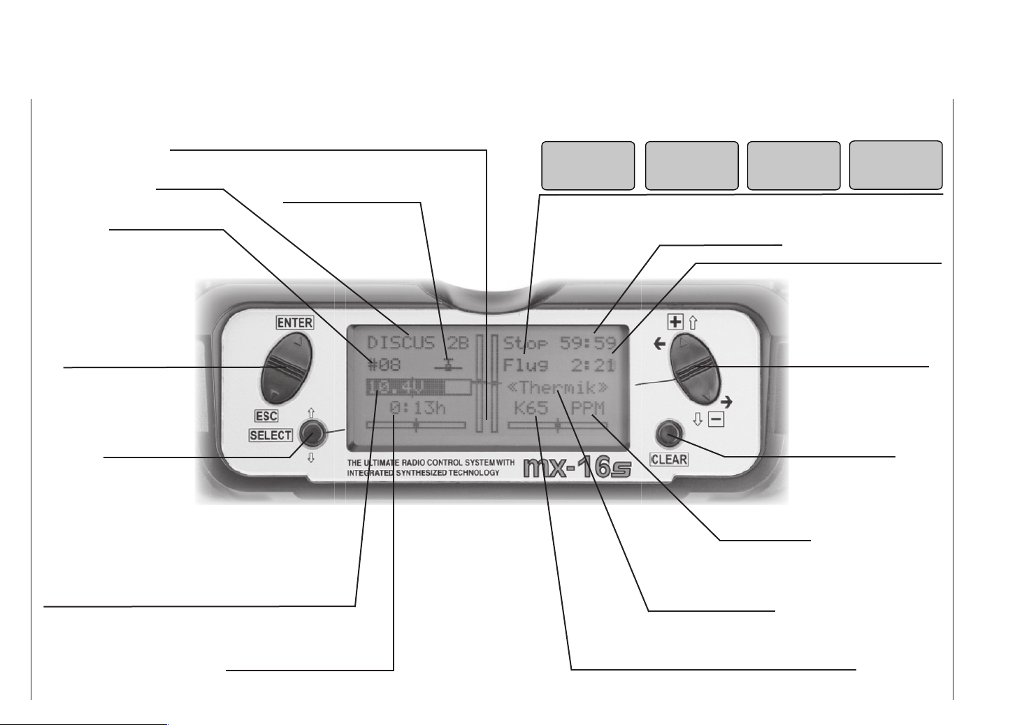
LCD screen and operating buttons
Model name
Memory 1 … 12
Left-hand rocker button
ENTER = confi rm
ESC = interrupt / back
SELECT button
Visual display of trim lever positions; alternatively – if the SELECT button is held pressed in – display of the current set-
tings of the two INC / DEC buttons (CTRL 5 + 6)
Model type display
(fi xed-wing / helicopter)
Error in Trainer mode Throttle stick dange-
no
student
signal
rously high
throttle
too
high !
Stopwatch in min : sec
(count-up / count-down)
Operating voltage in-
adequate
battery
needs
charging
Flight timer in min : sec
(count-up / count-down)
Right-hand rocker button
(value change)
CLEAR button
(erases, or resets
to default value)
SPCM mode only
adjust
fail
safe !
Battery voltage
(if voltage falls below a particular value a warning display
appears – see images at top right – and an audible warning
signal sounds)
Battery operating time since
last charge process, in hr : min
Description of transmitter – LCD screen and operating buttons
18
Modulation type
Flight phase name
transition between fl ight
phases using switch
Channel display
(fl ashes if RF section switched off; see pages 20 … 21)
Page 19
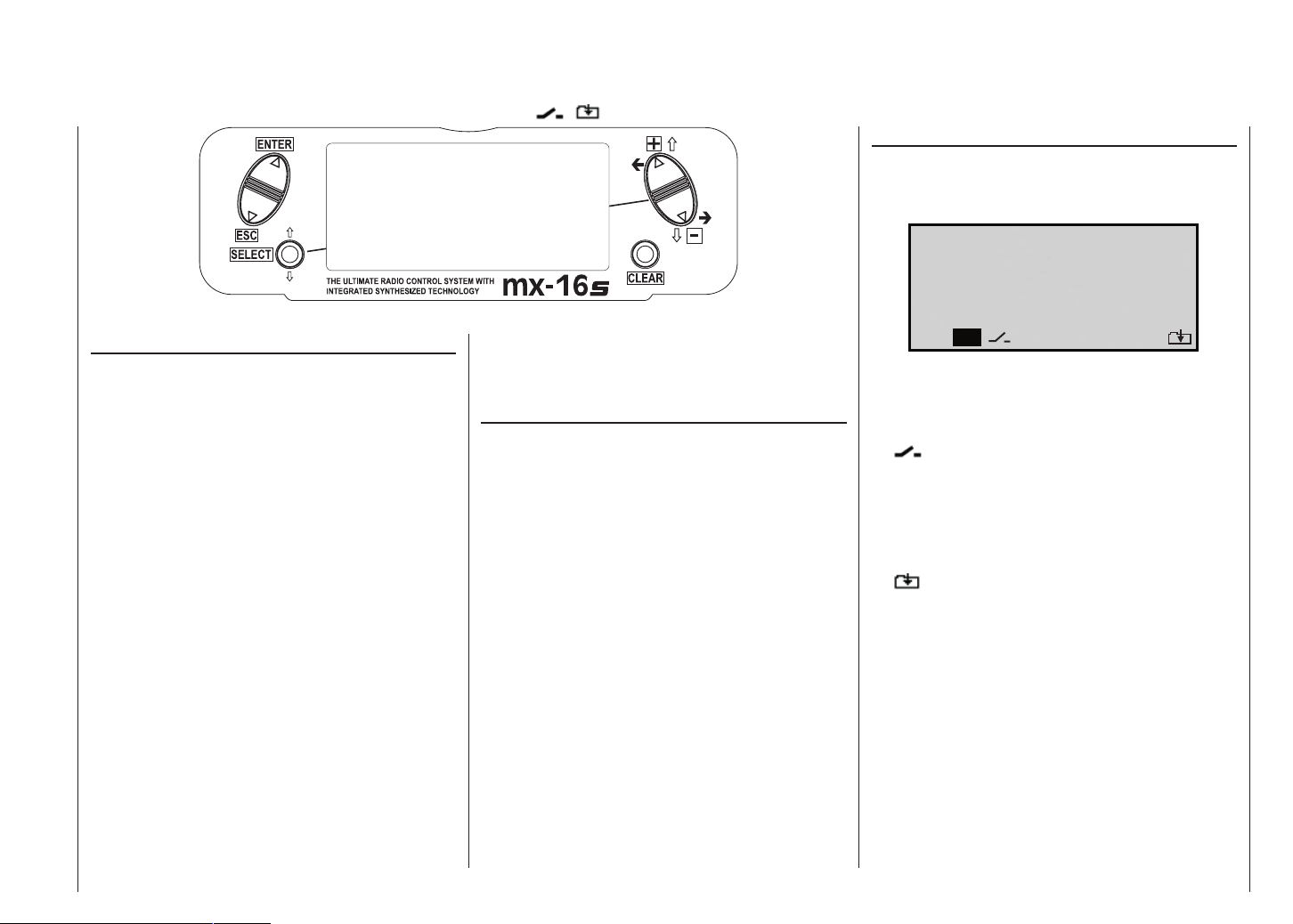
Controlling the “Data Terminal”
Input buttons and function fi elds
ENTER, ESC, SELECT, +, -, CLEAR ... SEL, STO, CLR, SYM, ASY, ,
ENTER button
(confi rm)
ESC button (interrupt / back)
Larger – up button
(+)
Smaller – down
button (-)
Function fi elds
Function fi elds appear in the bottom line of the screen
in certain menus; they can be selected using the righthand rocker button – .
SELECT button
Buttons to the left of the screen
• ENTER button, left-hand rocker button
Pressing ENTER takes you from Channel Select
(which appears when you switch the transmitter on)
to the basic display, and then on to the multi-function
menus. You can also call up a selected menu using
ENTER.
• ESC button, left-hand rocker button
Pressing the ESC button returns you step by step
within the function select system, taking you right
back to the basic display. If you make a change in the
meantime, the change is retained.
• SELECT
The SELECT button is used for several tasks:
1. A brief press switches from the basic transmitter
display to the »Servo display«; see page 27.
2. Hold the button pressed in to display the current
positions of the two INC / DEC buttons CTRL 5 +
6 in the basic display. The information is shown for
the duration of the button-press. See page 27.
3. Within the set-up menus press the SELECT button to activate the adjustment fi elds, and then
press SELECT again to return to the function
fi elds at the bottom edge of the screen.
4. If you hold the SELECT button pressed in, you
can “leaf through” the menu lines within the indi-
CLEAR
(reset to standard
value)
vidual set-up menus using the right-hand rocker
button – symbolised by above and below the
two buttons.
Buttons to the right of the screen
• “+” and “-“ buttons, right-hand rocker button
1. “Leaf through” the menu lines within the individual
menus when the SELECT button is held pressed
in – symbolised by above and below the two
buttons.
2. “Leaf through” lists, e.g. the model select or multi-
function list – symbolised by on both sides
of the right-hand rocker button.
3. Change between the function fi elds, most of
which are located at the bottom edge of the
screen; see right-hand column – symbolised by
on both sides of the right-hand rocker button.
4. Select and adjust parameters in the adjustment
fi elds, after activating them by pressing the SE-
LECT button – symbolised by + and – above and
below the right-hand rocker button.
• CLEAR
Resets a changed parameter value in the active input
fi eld to the default value.
S E L
S T O C L R
S Y M
A S Y
Press the SELECT button to activate a function fi eld.
Function fi elds
• SEL select
switch symbol fi eld
•
(assigning switches of all kinds)
• STO store (e.g. transmitter control position)
• CLR clear reset to default value
• SYM adjust values symmetrically
• ASY adjust values asymmetrically
• switch to second page (next menu) within a
menu
Description of transmitter – Operating buttons
19
Page 20
Using the system for the fi rst time
Channel selection
Preliminary notes
In its standard form the mx-16s is programmed to PPM
mode, and is therefore suitable for use with receivers of
the “FM-PPM” type. If you have purchased a standard
radio control set on the 35 or 40 / 41 MHz band, you can
immediately operate the supplied R16SCAN receiver in
this transmission mode.
The standard PPM mode of operation is supplemented by the SPCM mode, which is suitable for all
GRAUPNER/JR receivers of the “smc” type.
The ability of the mx-16s transmitter to switch transmission modes enables you to operate the unit with all
GRAUPNER receiving systems supplied with PPM-FM
and SPCM transmitters on the 35 and 40 / 41 MHz frequency bands.
For example, if you do not wish to use a “PPM” type receiver, the fi rst step is to change the modulation to suit
the type of receiver you wish to use. If you do not set
the transmitter correctly, the receiver simply will not
work with the transmitter. The transmission mode can be
changed in the »Base settings« menu (description: pa-
ges 38 and 42); the set mode only applies to the current
model memory.
Which crystals can you use?
The mx-16s requires no plug-in crystals. The transmission channel is selected by software: see later.
Battery charged?
When you take receipt of your transmitter, the battery
will be in the discharged state, so you must fi rst charge
it as described on pages 10 … 11. If you do not do this,
the battery will soon fall below the
pre-set threshold voltage, and you
will see and hear a warning signal
to remind you to recharge it.
battery
needs
charging
Aerial fi tted?
Never switch the transmitter on unless the aerial is screwed in. Even for prolonged testing you should always fi t
the aerial and extend it fully, otherwise the transmitter
may malfunction, with possible damage to the RF module.
When you wish to control a model it is fundamentally essential to screw the ten-section telescopic aerial into the
transmitter and extend it fully. Transmitter fi eld strength
is at a minimum in an imaginary line extending straight
out from the transmitter aerial. It is therefore fundamentally misguided to “point” the transmitter aerial at the model with the intention of obtaining good reception.
Switching the transmitter on / selecting a channel
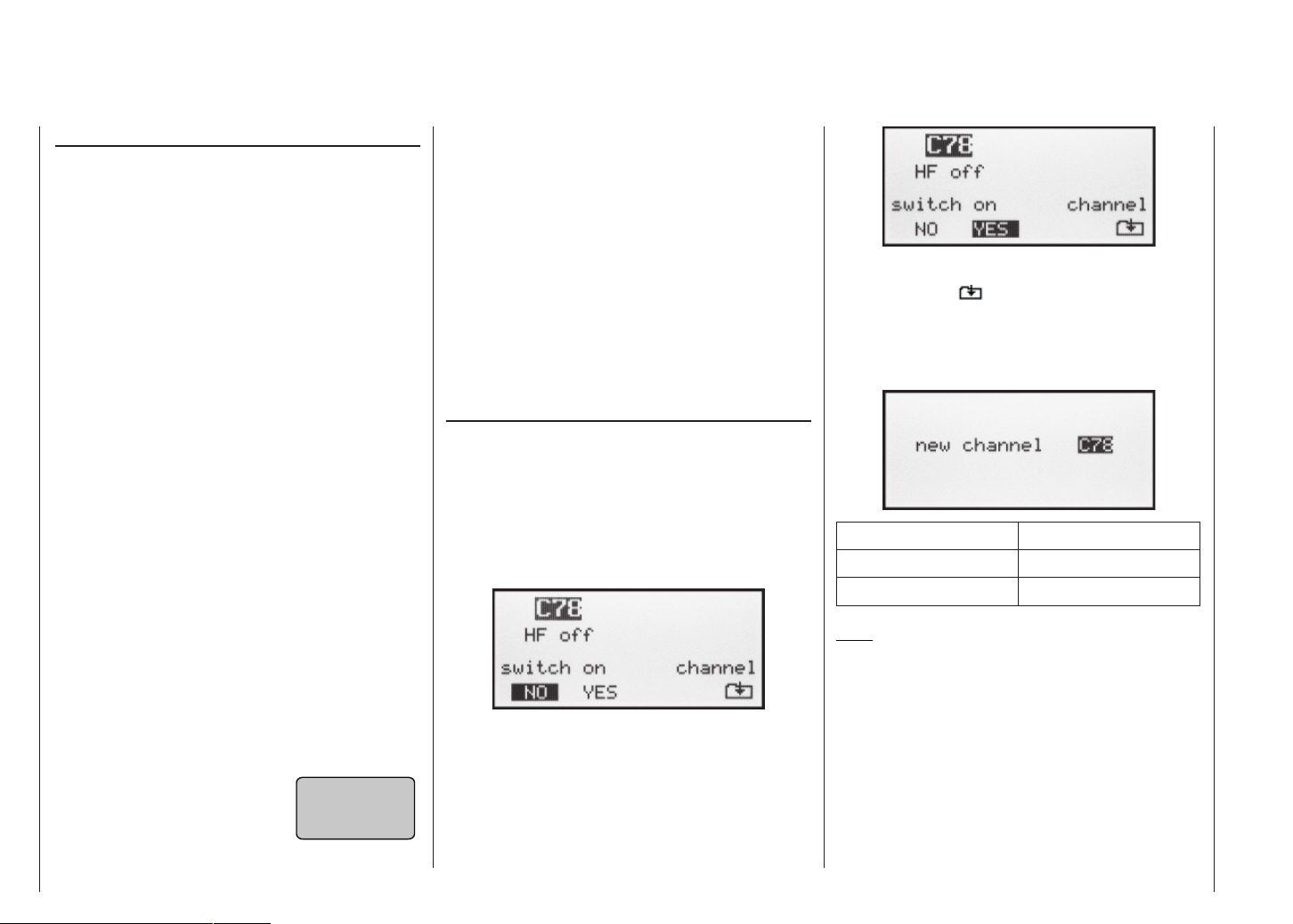
Every time you switch the transmitter on you must fi rst
confi rm to the integral synthesizer system that you wish
to use the set frequency. This takes the form of a security query, intended to prevent you switching the system
on accidentally whilst set to the wrong channel. The software asks you: “RF off / on”. The last set channel is initially highlighted (inverse video – black background) and
fl ashes:
If you wish to activate this channel, use the right-hand
rocker button to move the highlighted square to the
“Yes ” response in the function bar …
… and press the ENTER or SELECT button.
If not, move to the symbol at bottom right of the
screen. Press the ENTER or SELECT button to take
you to the Channel Select screen. The channels available at that point vary according to the RF module currently fi tted:
Frequency band Channels
35/35B MHz band 61 … 282, 182 … 191
40/41 MHz band 50 … 95, 400 ... 420
Note:
Channels 281 and 282 in the 35 MHz band, and all
channels in the 41 MHz band, are not approved for
use in Germany. Please refer to the frequency table on page 113, which lists the channels valid in the
European continent at time of going to press (information not guaranteed).
Use the right-hand rocker button to select the channel
you wish to use. However, please check before you do
this that no other model fl yer is operating a radio control
system on the channel you intend to use.
Description of transmitter – Using the system for the fi rst time
20
20
Page 21
Note:
You can switch directly to the channel with the lowest
number by pressing the CLEAR button.
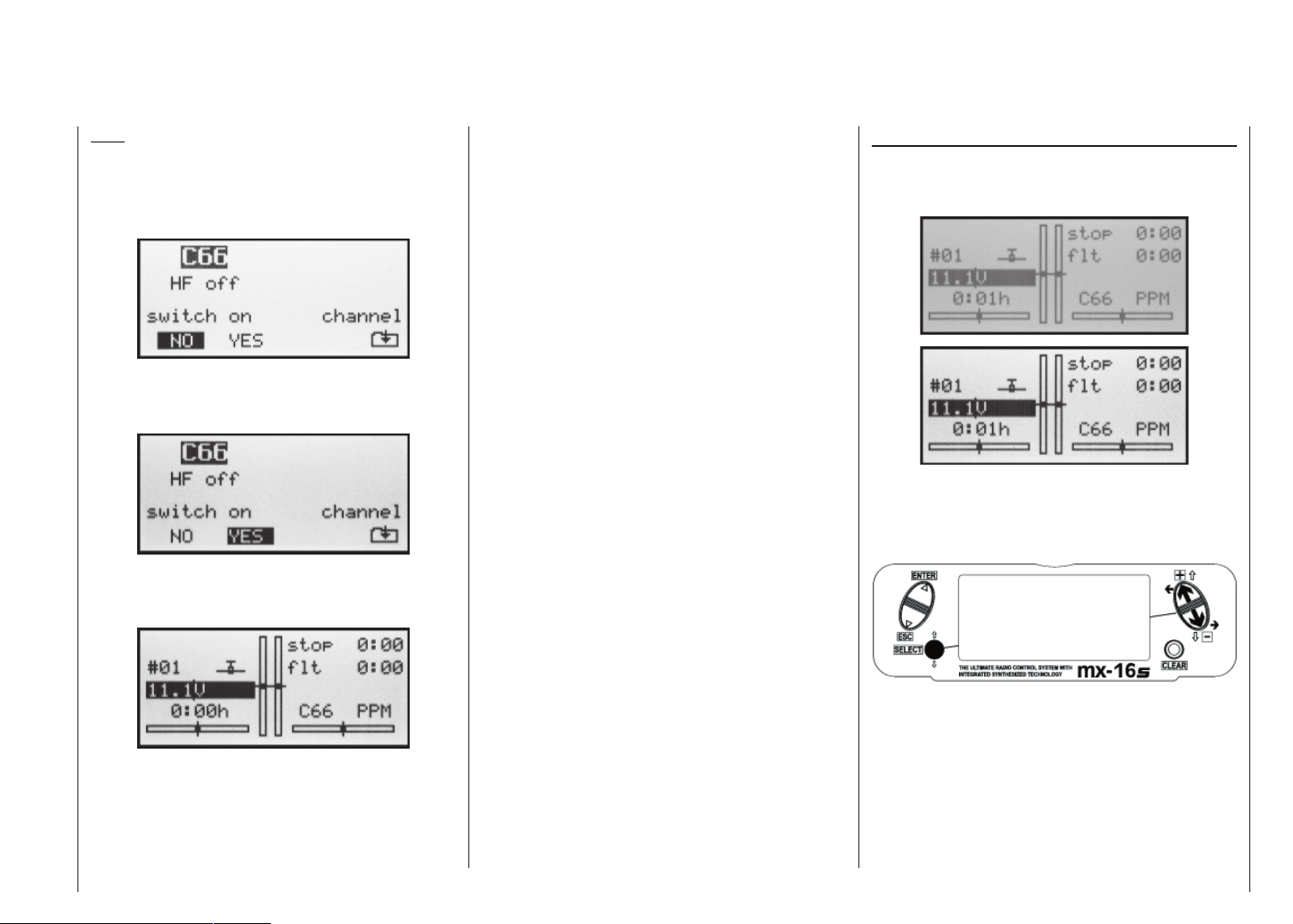
Press ENTER or ESC to confi rm your choice, and the
screen changes back to the previous screen page:
Now switch on the RF module as previously described, by moving the highlighted square to “Yes” using the
right-hand rocker button …
... and press the ENTER or SELECT button. The selected channel number now appears (no longer fl ashing) in
the basic display:
The transmitter is now ready for use.
If you wish to change the channel again, the transmitter
must fi rst be switched off, then on again.
You will fi nd a description of the basic procedure when
initially programming a new model memory on page 34;
helpful programming examples are in the section starting on page 86.
W A R N I N G
Never switch off the transmitter when you are fl ying
a model! If you do, you run a serious risk of losing
the model, as you will be highly unlikely to be able
to re-activate the RF signal quickly enough, since
the transmitter always responds with the security
query “RF signal on YES / NO” when switched on.
IMPORTANT NOTE
In the interest of maximum possible fl exibility, con-
trol channels 5 … 8 are not assigned to transmitter
controls by default; this also helps to eliminate the
danger of inadvertently using them incorrectly. For
the same reason virtually all the mixers are inactive
by default.
This means that in its standard form the transmitter can only control servos connected to receiver
output sockets 1 … 4 using the primary dual-axis
sticks. In contrast, any servos connected to receiver
sockets 5 … 8 remain fi xed at their centre position.
This situation only changes when you have carried
out the appropriate settings.
Description of transmitter – Using the system for the fi rst time
Adjusting screen contrast
The contrast of the LCD screen on the mx-16s transmitter is variable, to allow you to read the information clearly in all weathers and at all temperatures.
Hold the “SELECT” button pressed in when the transmitter screen is showing the basic display, then press
the “+” button for higher contrast, or the “-” button for lower contrast:
21
21
Page 22
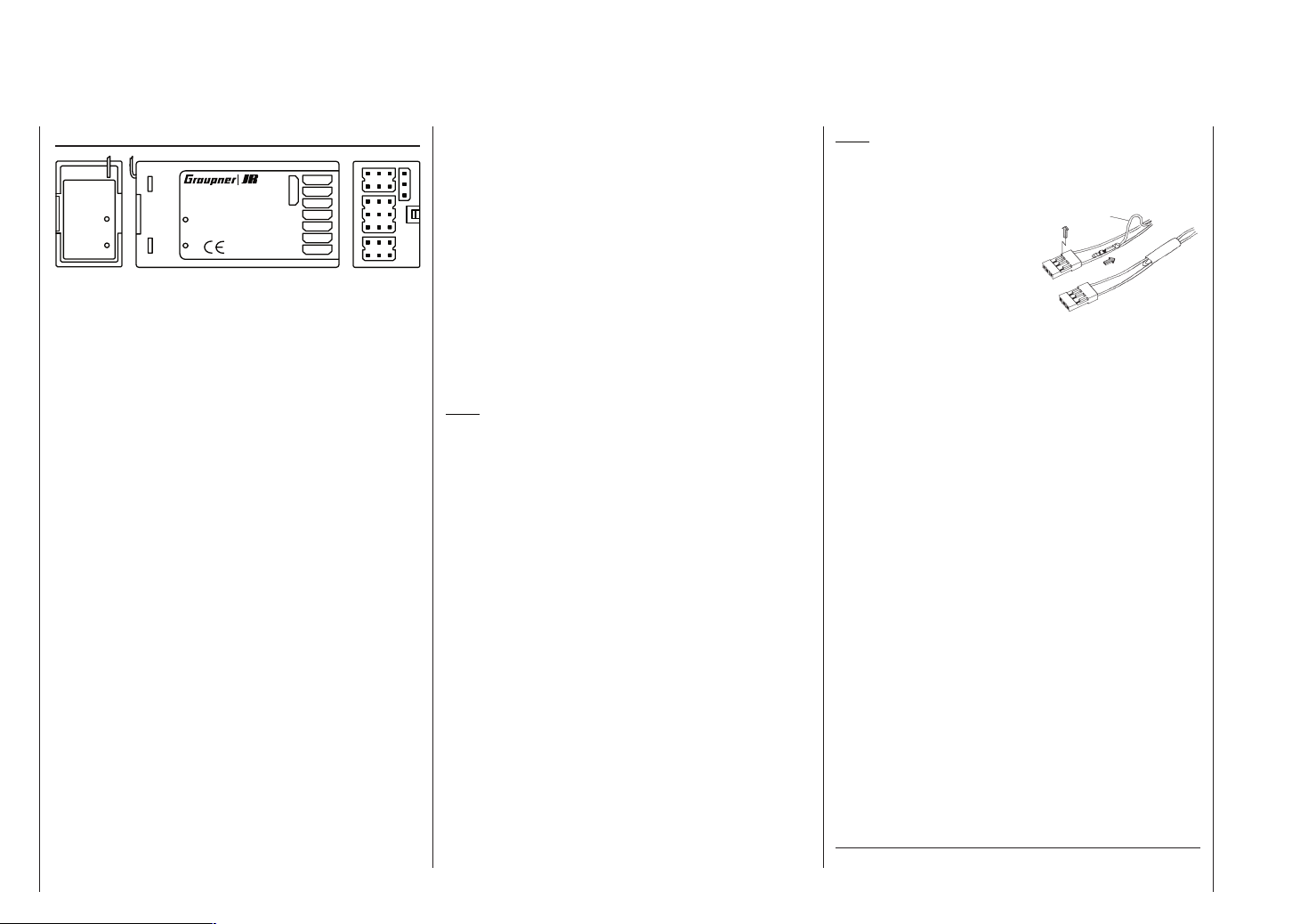
Using the receiving system for the fi rst time
Channel selection
Receiving system
Antenne
LED SCAN
PLL-Synthesizer-MICRO-SUPERHET
R 1 6
für das 35MHz/35MHz-B-Band
SCAN LED
Best.-Nr.
7052
Kanal 60-282/182-191
S C A N
Made in Malaysia
7
6
8/Batt.
5
4
FM
! #
3
2
1
The mx-16s radio control set is supplied complete with
a PLL-SCAN narrow-band FM superhet receiver on the
35 / 35B MHz band or the 40 / 41 MHz band. The following section describes how to set the receiver channel
to match the transmitter’s channel. The approved channels at the time of going to press are listed in the table
on page 113.
If you are using the standard receiver, you need to set
the transmitter to PPM transmission mode. You must not
activate the channel on the transmitter until you have
checked carefully that no other pilot is fl ying his model
on your chosen frequency. When you are sure, switch
the receiver on. You will see a blue LED light up on the
receiver, indicating that the unit is (basically) ready for
use.
Setting the receiver to match the transmitter channel
1. Prepare the transmitter ready for use, with the aerial
fi tted and extended, and place it in the immediate vicinity of the receiver. The scan program which is run
next binds the receiver to the most powerful transmitter signal, so you must ensure that no other radio
control transmitter is located very close to your receiver.
2. Locate the push-button marked “SCAN” on the receiver, and use a tool such as a ball-point pen to hold
the button pressed in until the LED goes out; this
takes about three seconds.
Using the receiving system for the fi rst time
22
3. Press the SCAN button again immediately when the
LED goes out: the LED now fl ashes at a high rate.
This indicates that the “Scan” process is under way.
As soon as the receiver “fi nds” the transmitter frequency, the LED will glow again constantly. The receiver stores this channel, so that you do not need to
repeat the process each time you switch the receiver
on; you only need to do this if you change channels.
4. If the LED fl ashes slowly after a few seconds, it is unable to lock onto the transmitter frequency. Check the
transmitter, then repeat steps 1 to 3.
Always carry out a range check with the model on the
ground before every fl ight.
Note:
If you wish to connect a servo in parallel with the receiver battery, i.e. to the socket on the R16SCAN receiver marked “8/Batt”, you need to use a Y-lead, Order No.
3936.11 or 3936.32. As the socket is now in use for two
purposes, Diagnosis mode operations (see pages 15 …
16) are not possible with this receiver.
Please read the information on installing the receiver
and receiver aerial on pages 3 to 5 of these instructions.
If you wish to use a different GRAUPNER receiver, ple-
ase note that you must set the appropriate transmission
mode (PPM or SPCM) on the transmitter; the frequency band and channel number of the receiver must also
match those of the transmitter.
The receiver is fi tted with polarised connector sockets,
so that the servos and battery can only be connected
the right way round. Genuine GRAUPNER plugs feature
a slight chamfer on one side to match the sockets. Connect the receiver battery to the receiver socket marked
“8/Batt” via an ON / OFF switch harness.
Note:
If you wish to use a receiver battery and a speed controller with integral BEC* system, the positive (red) wire
must normally be disconnected from the 3-pin plug, although this does vary according to the type of controller. Please be sure to read
the instructions supplied with
red
1
2
3
your speed controller before
you do this.
Using a small screwdriver, carefully raise the centre lug
of the plug (1), withdraw the red wire (2) and insulate the
exposed contact with insulating tape to prevent possible
short-circuits (3).
* Battery Elimination Circuit
Page 23
Installation notes
Your receiving system must be installed correctly in the
model. The following are a few suggestions when using
GRAUPNER equipment:
1. Wrap the receiver in (anti-static) foam rubber at least
6 mm thick. Fix the foam round the receiver using
rubber bands, to protect it from vibration, hard landings and crash damage.
2. The receiver aerial must be secured in the model, so
that there is no chance of it becoming tangled in the
propeller or control surfaces. However, it is best not
to deploy the aerial in an exactly straight line, but to
angle it: e.g. run it straight to the tailplane, then leave the fi nal 10 - 15 cm trailing freely, as this avoids
reception “blind spots” when the model is in the air. If
this is not possible, we recommend that you lay out
part of the aerial wire in an S-shape inside the model, as close to the receiver as possible.
3. All switches must be installed in a position where
they will not be affected by exhaust gases or vibration. The switch toggle must be free to move over its
full range of travel.
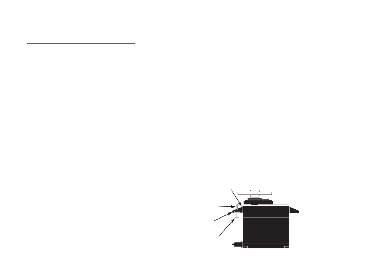
4. Always install servos using the vibration-damping
grommets and tubular metal spacers supplied. The
rubber grommets provide some degree of protection
from mechanical shocks and severe vibration. Don’t
over-tighten the servo retaining screws, as this will
compress the grommets and thereby reduce the vibration protection they afford. The system offers good
security and vibration protection for your servos, but
only if the servo retaining screws are fi tted and tightened properly. The picture on the right shows how to
install a servo correctly. The brass spacers should be
pushed into the rubber grommets from the underside.
5. The servo output arms must be free to move over
their full arc of travel. Ensure that no parts of the mechanical linkage can obstruct the servo in its move-
ment.
The sequence in which the servos are connected to the
receiver is dictated by the model type. Please see the
socket assignments listed on pages 29 / 30 and 33.
Be sure to read the safety notes on pages 3 … 5.
If the receiver is ever switched on when the transmit-
ter is off, the servos may carry out uncontrolled movements. You can avoid this by switching the system on in
this order:
Always switch the transmitter on fi rst,
then the receiver.
When switching the system off:
Always switch the receiver off fi rst,
then the transmitter.
When programming the transmitter you must always
ensure that any electric motors in the system cannot
possibly burst into life accidentally, and that an I.C. engine fi tted with an automatic starter cannot start unintentionally. In the interests of safety it is always best to dis-
Servo mounting lug
Retaining screw
Rubber grommet
Brass tubular spacer
connect the fl ight battery, or cut off the fuel supply.
Range checking:
Before every session you should always check that each
working system is functioning correctly, and carry out a
range check with the model on the ground. The transmitter aerial should be fi tted but collapsed completely, and
should be taken a suitable distance away from the model. All the functions should work smoothly and correctly during this test. If your model is powered, repeat the
check with the motor running to ensure that it does not
cause interference.
Using the receiving system for the fi rst time
23
Page 24

Defi nition of terms
Control functions, transmitter controls, function inputs, control channels, mixers, switches, control switches
To make it easier for you to understand the mx-16s manual, the following two pages contain defi nitions of many
terms which crop up again and again in the remainder of
the text, together with a basic fl ow diagram showing the
course of the signal from the transmitter control to the
point at which it is radiated from the transmitter aerial.
Control function
The term “control function” can be thought of as the signal generated for a particular function which needs to be
controlled – initially independent of its subsequent progress through the transmitter. In the case of fi xed-wing
model aircraft the control functions include throttle, rudder and aileron, whereas collective pitch, roll-axis and
pitch-axis are typical of those used for helicopters. The
signal of a control function may be assigned directly, or
to several control channels simultaneously via mixers.
A typical example of the latter is separate aileron servos, or pairs of roll-axis or pitch-axis servos in a model
helicopter. The essential feature of a control function is
its infl uence on the mechanical travel of the corresponding servo.
Transmitter control
The term “transmitter control” is used for the mechanical elements on the transmitter which are operated directly by the pilot. Their movements in turn generate corresponding movements in the servos, speed controllers
etc. at the receiver end. The transmitter controls include
the following:
• The two dual-axis stick units for the control functions
1 to 4; these four functions can be interchanged in
any way you like through software, e.g. throttle left
or right, without having to re-connect the servos; this
applies to both fi xed-wing model aircraft and helicopters. The dual-axis stick function for throttle (or airbrakes) is often referred to as the C1 (Channel 1) cont-
Description of transmitter – Defi nition of terms
24
rol.
• The rotary proportional control fi tted at top left (CTRL
7)
• The INC / DEC buttons (CTRL 5 + 6) located on eit-
her side of the aerial base.
• Switches SW 1 … .8, if they have been assigned to a
control channel in the “Control settings” menu.
When a proportional transmitter control is operated, the
servo or servos follow the position of the control directly, whereas a switched channel provides just the two or
three set servo positions.
Function input
This is an imaginary point in the signal path, and must
not be considered the same as the point on the circuit
board where the transmitter control is connected! The
two menus »Stick mode« and »Control settings« affect the course of the signal “after” these points, and it
is possible (and likely) that there will be differences between the number of the transmitter control (as stated
above) and the number of the subsequent control channel.
Control channel
There is a point in the signal path where the signal contains all the control information required for a particular
servo – this may be directly generated by a transmitter
control or indirectly via a mixer – and from this point on
we call the signal a control channel. This signal is specifi c to an individual servo, and is only affected by any adjustments carried out in the “Servo settings” menu before leaving the transmitter via the RF module in order to
actuate the corresponding servo in the model.
Mixer
In the signal fl ow diagram you will see a wide range of
mixer functions. Their purpose is to enable a control
function to affect multiple servos at the branching point
of the mixer input; the range of mixer programs is extremely wide-ranging. For more information please refer to
the numerous mixer functions as described in the section starting on page 61 of the manual.
Switch
The three standard switches SW 1 … 3, the three-position switch SW 6/7 and the momentary buttons SW 4 /
PB 8 can also be incorporated into the programming of
the transmitter controls. However, all these switches are
also capable of controlling various program options, e.g.
starting and stopping timers, switching mixers on and
off, transferring control in Trainer mode etc. Each physical switch function can be assigned to as many functions as you wish.
Numerous examples are described in the manual.
Transmitter control switch
It is often desirable to switch a function on or off automatically at a particular position of another transmitter
control, e.g. at a defi ned position of one of the dual-axis
sticks. Typical examples are switching a stopwatch on
and off to allow you to record the motor run time, extending spoilers automatically (and many others). The program of the mx-16s includes a total of two (or three – for
helicopters) “control switches” of this type.
Two transmitter control switches are available for the C1
stick in each model memory, both for fi xed-wing model
aircraft and helicopters. For helicopters a third is present
in the form of the throttle limiter; see pages 25 and 54.
This manual includes a range of instructive examples
which make programming as simple as child’s play. Please refer to the programming examples in the section
starting on page 84.
Page 25

Assigning switches and control switches
The basic procedure
At many points in the program there is the option of
using a switch (SW 1 … 4, SW 6/7, PB 8) or a control switch (G1 … 3; see below) to operate a function, or
to switch between settings, such as the DUAL RATE /
EXPO function, fl ight phase programming, mixers and
more. The mx-16s allows you to assign several functions
to a single switch.
The process of assigning switches is exactly the same in
all the relevant menus, and we will explain the basic programming procedure at this point so that you can concentrate on the special features when reading the detailed menu descriptions.
A switch symbol appears in the bottom line of the screen
at all programming points where switches can be assigned:
If you move to this fi eld using the right-hand rocker button, the switch symbol fi eld is highlighted (inverse video
– black background):
The procedure for assigning a switch
1. Press the SELECT button.
The following message appears in the display:
2. Now simply move the switch you wish to use to the
“ON” position, press the push-button, or move the
C1 stick from the “OFF” position in the direction of
“ON”. Please note: the so-called control switches assigned to this transmitter control (see right) carry out
the task of an ON / OFF switch in software; the same
applies to the throttle limiter (see page 54) which is
available in the “Helicopter” model type. This comple-
tes the assignment process.
3. Changing the direction of switching:
If the switch turns out to work in the wrong direction,
you can correct it as follows: move the switch to the
desired OFF position, select the switch symbol once
more and assign the switch again, this time with the
switch direction you prefer.
4. Erasing a switch:
Activate the switch symbol as described under Point
2, then press the CLEAR button.
Special feature: SW 4 / PB 8
This “push-button” can be assigned in two ways:
• A brief press as On / Off switch “4”, i.e. the switched
state (“on” or “off”) changes every time you press the
button.
• A longer press as momentary button “8”, i.e. the
switch is only ON as long as the button is held
pressed in.
Note:
Every time you switch the transmitter on, switch 4 always defaults to the “OFF” position.
Transmitter control switches
Many functions are best controlled automatically by
a particular (freely programmable) position of the C1
transmitter stick (or the throttle limiter in the case of helicopters), rather than by a conventional physical switch.
Typical applications:
• Automatically switching an on-board glowplug energizer on and off according to the throttle position of the
C1 stick (“G1” or “G2”). In this case the switch for the
plug energizer is controlled by a mixer at the transmitter.
• Automatically switching a stopwatch on and off to re-
cord the pure “fl ight time” of a model helicopter; this
is accomplished using the “G3” switch of the throttle
limiter.
• Automatically switching the “AIL RUD” mixer off
when the airbrakes are extended, in order to keep the
wings parallel with the ground when landing on a slope face, without the (usually coupled) rudder affecting the model’s heading.
• Automatically extending landing fl aps with coupled
elevator trim adjustment on the landing approach,
as soon as the throttle stick is reduced below the set
threshold point.
• Automatically switching a stopwatch on and off in order to time the run of an electric motor.
For both model types the mx-16s transmitter’s software caters for these purposes with two “control switches”
of this type; they can be assigned to the C1 stick: “G1”
is switched on at around -80% of full travel, while “G2”
is switched on at around +80%. The Helicopter program
also includes an extra control switch “G3” on the throttle
limiter close to the 100% point; see page 54.
All these control switches can be included without restriction in the free programming of the switches, i.e.
they can be assigned to a function instead of a physical switch. This means that you are able to assign one of
the control switches G1 … G2 (or G1 … G3) instead of
a physical switch at any point in the software where switches are assigned. All you have to do is move the C1
stick or the throttle limiter control (by default the rotary
proportional control CTRL 7) from the desired “OFF” position in the direction of “ON”.
Description of transmitter – switch assignment
25
Page 26
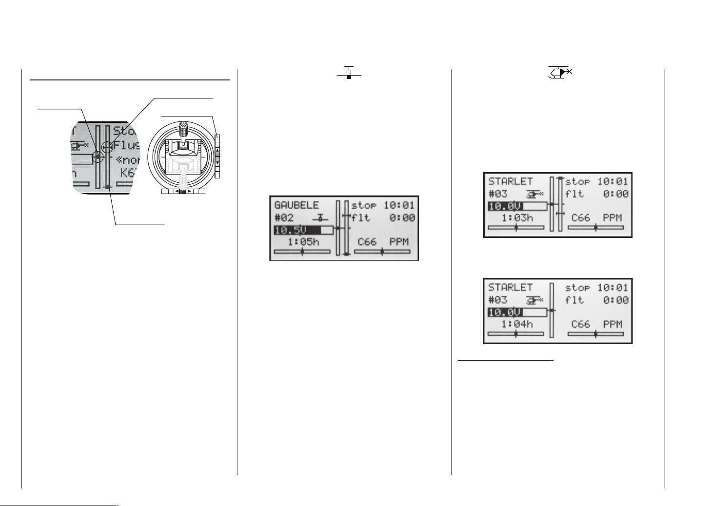
Digital trims
Description of function, and C1 cut-off trim
Digital trims with visual and audible indicators
Current trim
position
Trim at motor
OFF position
Both the dual-axis stick units are fi tted with digital trim
systems. When you give the trim lever a brief push (one
“click”), the neutral position of the stick channel changes
by one increment. If you hold the trim lever in one direction, the trim value changes continuously in the corresponding direction with increasing speed.
The degree of trim offset is also “audible”, as the pitch
of the tone changes to refl ect the setting. When you are
fl ying a model, you can fi nd the trim centre position easily without having to look at the screen: if you over-run
the centre setting, the trim stays in the centre position
for a moment.
The current trim values are automatically stored when
you switch from one model memory to another. The digital trims are also stored separately for each fl ight phase within a model memory, with the exception of the “C1”
(Channel 1) trim, which is the throttle / airbrake trim on a
fi xed-wing model.
The C1 trim includes another special function which
makes it easy to re-locate the idle throttle setting of a
glowplug motor.
Last idle position
C1 trim lever
1. Fixed-wing models
The C1 trim features a special cut-off trim which is designed for glowplug motors:
You initially use the trim lever in the usual way to select
a reliable idle setting for the motor. If you now move the
C1 trim lever to its end-point in the direction of “motor
cut-off”, pushing the lever in a single movement, a marker appears on the screen in the last position. You can
now return to the idle setting for starting the motor simply by pushing the stick one click in the direction of “open
throttle”.
The cut-off trim feature is disabled if you enter “none” in
the motor line within the »Base settings« menu (page
38).
2. Model helicopters
In helicopter mode the C1 trim has another feature in
addition to “cut-off trim”, as described under “Fixedwing models” on the left; this time in conjunction with the
“Throttle limit function” (see page 54): while the throttle limit slider is in the bottom half of its travel, i.e. in the
“start-up range”, the C1 trim lever acts as idle trim on
the throttle limit, and the idle trim is displayed on the
screen:
In contrast to a fi xed-wing model aircraft, this display is
suppressed if the throttle limit control is moved to the
“upper” half of its travel.
Note regarding helicopters:
The C1 trim only affects the throttle servo and not the
collective pitch servos; it also works evenly over the full
stick travel. Please note that the helicopter throttle servo must be connected to receiver output 6 (see Receiver
socket assignment, page 33).
Description of transmitter – Digital trims
26
Page 27
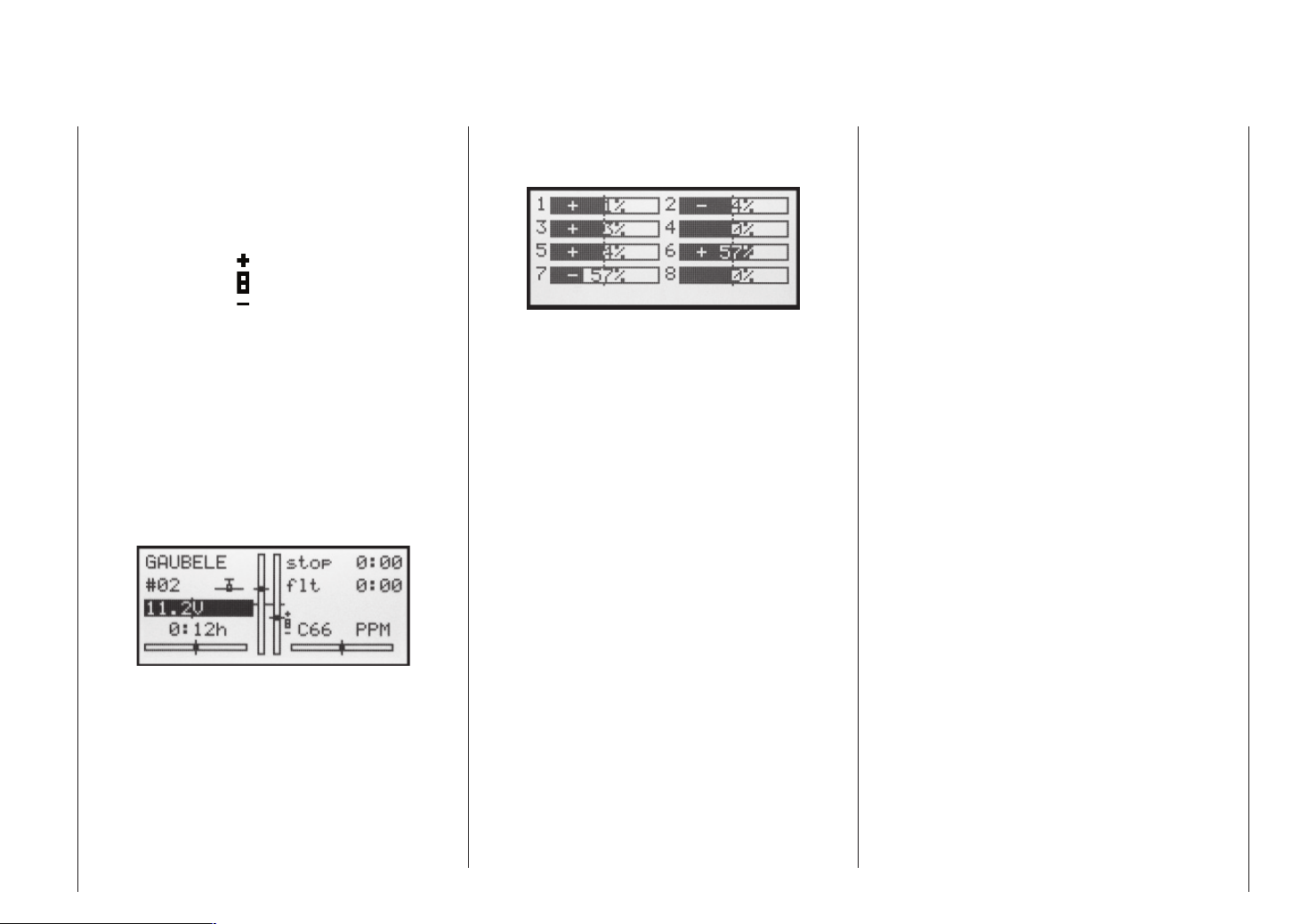
Position display
INC / DEC button, CTRL 5 + 6
Servo display
Holding the SELECT button held in while you are at the
transmitter’s basic display calls up a visual display of the
current positions of the two INC / DEC buttons (CTRL
5 + 6). This display disappears again when you release
the SELECT button. At the same time a small symbol
appears on the left, adjacent to the channel display:
When you hold the SELECT button pressed in, the position display on the basic transmitter display, consisting
of the two central vertical bars, also changes: it switches
from a display of the current trim position to the current
position of the INC / DEC buttons, CTRL 5 + 6.
As you would expect, the left-hand bar represents the
position of the INC / DEC button CTRL 6, located to the
left of the aerial base, and the right-hand bar shows the
position of CTRL 5 (however, both horizontal bars continue to show the current position of the corresponding
transmitter stick trim levers):
As soon as you release the SELECT button, the screen
reverts to a display of the current trim position of the
four trim levers of the two dual-axis stick units; see picture left.
Pressing the SELECT button at the transmitter’s basic
display calls up a visual representation of the current
servo positions on the transmitter screen.
This display shows the current position of every servo in the form of a bar diagram, taking into account the
transmitter control and servo settings, the Dual Rate /
Expo functions, the inter-action of all active mixers etc.
The display is accurate, and covers the range -150% to
+150% of normal travel. 0% means the exact centre position. This allows you to check your settings quickly without even having to switch the receiver on. However,
this does not mean that you don’t need to bother checking all the programming steps on the model; you must
do this carefully before operating it for the fi rst time, as
this is the only reliable method of picking up and correcting errors.
For fi xed-wing model aircraft the display shows the
information arranged in the following way:
Bar 1 = Throttle / brake servo
Bar 2 = Aileron or left aileron
Bar 3 = Elevator
Bar 4 = Rudder
Bar 5 = Right aileron
Bar 6 = Left camber-changing fl ap / free channel
Bar 7 = Right camber-changing fl ap / free channel
Bar 8 = Free channel
… and for model helicopters:
Bar 1 = Collective pitch or roll (2) or nick (2)
servo
Bar 2 = Roll (1) servo
Bar 3 = Nick (1) servo
Bar 4 = Tail rotor servo (gyro)
Bar 5 = Nick (2) servo / free channel
Bar 6 = Throttle servo or speed controller
Bar 7 = Gyro gain / free channel
Bar 8 = Speed controller / free channel
Description of transmitter – Servo display
27
Page 28
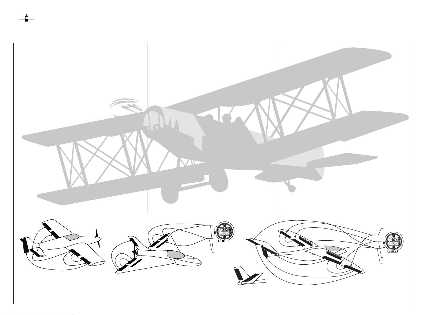
Fixed-wing model aircraft
This program provides convenient support for models
with up to two aileron servos and two fl ap servos (conventional aircraft), V-tail models, fl ying wings and deltas
with two elevon (aileron / elevator) servos and two fl ap
servos.
The majority of power models and gliders belong to the
“normal” tail type with one servo each for elevator, rudder, ailerons and throttle or electronic speed controller
(airbrakes on a glider). There is also the special model
type “2 EL Sv” which provides a means of connecting
two elevator servos in parallel to channels 3 and 8.
If your model features two separate aileron servos (and
also in some cases two fl ap servos), the aileron travel
of both pairs of control surfaces can be set up with differential movement in the »Wing mixers« menu, i.e. the
down-travel can be set independently of the up-travel.
Finally the program caters for camber-changing fl aps,
which can be operated by any of the transmitter controls “CTRL 5 … 7”. Alternatively a phase-specifi c trim is
available for fl aps, ailerons and elevator in the »Phase
trim« menu.
n
o
r
e
l
i
A
Õ
r
p
a
l
o
F
t
Õ
r
a
o
v
t
e
a
l
v
E
e
l
E
r
o
t
a
v
e
l
E
A
Õ
p
a
l
F
F
i
l
e
l
a
r
o
p
n
Õ
Õ
p
F
a
l
A
i
l
e
r
A
i
l
o
n
Õ
e
r
o
R
n
u
d
d
e
r
r
e
d
d
u
R
Õ
n
o
r
e
l
i
A
t
o
r
a
v
e
l
E
F
l
a
p
Õ
Õ
r
o
p
t
a
a
l
v
F
e
l
E
If the model features a V-tail instead of a conventional
tail, you need to select the tail type “V-tail” in the »Base
settings« menu, as this automatically superimposes the
elevator and rudder control functions in such a way that
each tail panel can be actuated by a separate servo.
For deltas and fl ying wings it is easy to set up mixed elevons, i.e. the aileron and elevator functions can be carried out via common control surfaces at the trailing edge
of the right and left wing. As standard the program contains the appropriate mixer functions for the two servos.
Up to three fl ight phases can be programmed in each of
the 12 model memories.
The digital trim positions are stored separately for each
fl ight phase, with the exception of the C1 trim. The C1
trim provides a simple means of re-locating the correct
idle throttle setting.
Two timers are available at all times when fl ying. The
screen also displays the transmitter operating time since
the battery was last charged.
The switches SW 1 … 8 and the transmitter controls
CTRL 5 … 7 can be assigned to any of the inputs 5 … 8
in the »Control settings« menu.
Airbrake-Function 1
F
Õ
l
a
n
p
o
r
e
l
i
A
left
right
Airbrake Õ Flap
Airbrake
Õ
Elevator
Rudder/Elevator
left
V-Tail
right
“Dual Rate” and “Exponential” can be programmed separately for aileron, rudder and elevator, giving two modes of control.
Depending on the model type you have selected, the
»Wing mixers« menu presents you with up to 12 additional pre-defi ned mixers and coupling functions which
you can simply select and set up when necessary, in addition to three free mixers:
1. Aileron differential
2. Flap differential
3. Aileron rudder (switchable)
4. Aileron fl ap (switchable)
5. Airbrake elevator (switchable)
6. Airbrake fl ap (switchable)
7. Airbrake aileron (switchable)
8. Elevator fl ap (switchable)
9. Elevator Aileron (switchable)
10. Flap elevator (switchable)
11. Flap aileron (switchable)
12. Differential reduction
Airbrake
F
l
A
a
i
p
l
e
Õ
r
o
n
o
A
r
e
i
l
n
Õ
F
l
a
p
E
l
e
v
a
t
o
r
p
a
l
F
Õ
F
Õ
l
a
p
e
l
E
A
i
l
e
r
o
Õ
n
R
E
l
e
v
Õ
a
t
o
r
A
A
i
l
F
e
l
r
r
o
t
a
v
u
d
d
e
r
n
o
r
e
l
i
a
o
p
n
Õ
Õ
n
o
r
e
l
A
i
F
l
a
p
Airbrake Õ Flap
Airbrake
Õ
Aileron
Õ
Elevator
Fixed-wing model aircraft
28
Page 29
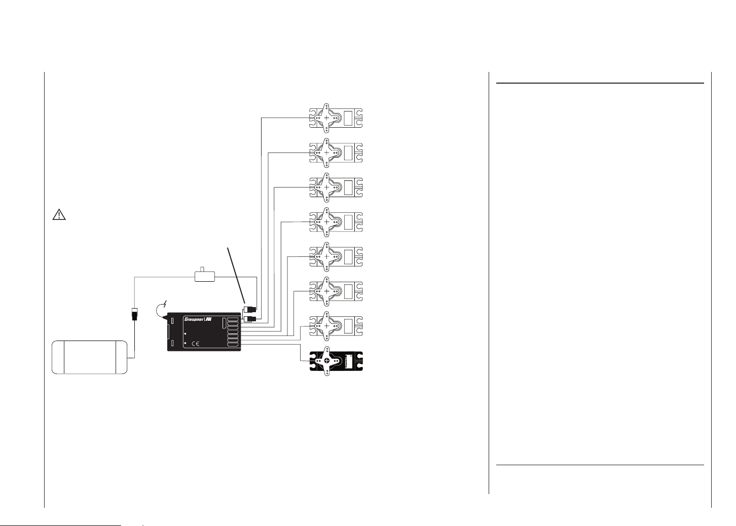
Receiver socket assignment for models with up to two ailerons and two fl aps, plus “normal” tail type, V-tail,
and two elevator servos (3 + 8)
8 = 2nd elevator / auxiliary func.
7 = Right fl ap / reserve
6 = Left fl ap / reserve
WARNING
Do not shorten the aerial!
Receiver
battery
Switch harness
Receiver aerial
Y-lead, Order No.
3936.11 or 3936.32
Best.-Nr.
7
7052
S C A N
Made in Malaysia
6
8/Batt.
5
4
FM
! #
3
2
1
PLL-Synthesizer-MICRO-SUPERHET
Kanal 60-282/182-191
R 1 6
für das 35MHz/35MHz-B-Band
SCAN LED
5 = Right aileron / reserve
4 = Rudder / right V-tail
3 = Elevator / left V-tail
2 = Aileron / left aileron
4,8 V
1 = Throttle / brake
C 577
Servo
Best.-Nr. 4101
Installation notes
The servos must be connected to the receiver outputs in the following order:
Outputs not required are simply left vacant. Please note
the following points in particular:
• If you are using only one aileron servo, receiver output 5 (right aileron) is left unused; it can also be used
for another purpose if you select “1 AIL” in the »Base
settings« menu.
• If you are using only one fl ap servo, receiver output 7 (right fl ap) must be left unused, assuming that
you have selected “... 2 FL” in the »Base settings«
menu.
If you are using a Graupner transmitter to control a model fi tted with a PPM-FM receiving system made by another manufacturer*, which was formerly fl own using a
different make of transmitter, e.g. when using the mx16s for Trainer mode operations, it may be necessary to
re-arrange the servo sequence at the receiver outputs
as shown in the diagram on the left. However, an alternative method is to use the »Receiver output« submenu of the »Base settings« menu; see page 41. Dif-
ferent methods of installing servos and control linkages
may make it necessary to reverse the direction of rotation of some servos when programming. In both cases
this is carried out in the »Servo settings« menu; see
page 48.
Please also read the information on the following
pages.
*
GRAUPNER does not guarantee that GRAUPNER radio control sys-
tems will work correctly in conjunction with receiving systems and
radio control equipment made by other manufacturers.
Fixed-wing models – Installation and connection
29
Page 30
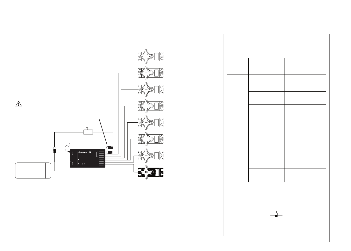
Receiver socket assignment for models of the “Delta / Flying wing” type, with up to two fl aps
8 = Auxiliary function
7 = Right fl ap / reserve
6 = Left fl ap / reserve
WARNING
Do not shorten the aerial!
Receiver
battery
Y-lead, Order No.
3936.11 or 3936.32
Switch harness
Receiver aerial
Best.-Nr.
PLL-Synthesizer-MICRO-SUPERHET
Kanal 60-282/182-191
R 1 6
S C A N
für das 35MHz/35MHz-B-Band
Made in Malaysia
SCAN LED
7
7052
6
8/Batt.
5
4
FM
! #
3
2
1
5 = Reserve
4 = Rudder
3 = Right elevon
2 = Left elevon
4,8 V
1 = Throttle / brake
C 577
Servo
Best.-Nr. 4101
As there are several possible combinations of servo orientation and control surface linkage, you may fi nd that
the direction of rotation of one or more servos is incorrect. Use the following table to solve the problem.
Model
type
Servo rotating
in wrong
Remedy
direction
V-tail
Delta,
fl ying wing
Rudder and elevator
reversed
Rudder correct,
elevator reversed
Elevator correct
rudder reversed
Elevator and ailerons
reversed
Elevator correct,
ailerons reversed
Ailerons correct,
elevator reversed
Reverse servos 3 + 4 in
the »Servo settings«
menu
Swap over servos 3 + 4
at the receiver
Reverse servos 3 + 4 in
the »Servo settings«
menu, and swap over at
the receiver
Reverse servos 2 + 3 in
the »Servo settings«
menu
Reverse servos 2 + 3 in
the »Servo settings«
menu, and swap over at
the receiver
Swap over servos 2 + 3
at the receiver
Fixed-wing models – Installation and connections
30
All menus which are relevant to fi xed-wing models are
marked with an “aeroplane” symbol in the “Program descriptions”:
This means that you can easily skip irrelevant menus
when programming a fi xed-wing model aircraft.
Page 31

Fixed-wing models – Installation and connections
31
Page 32
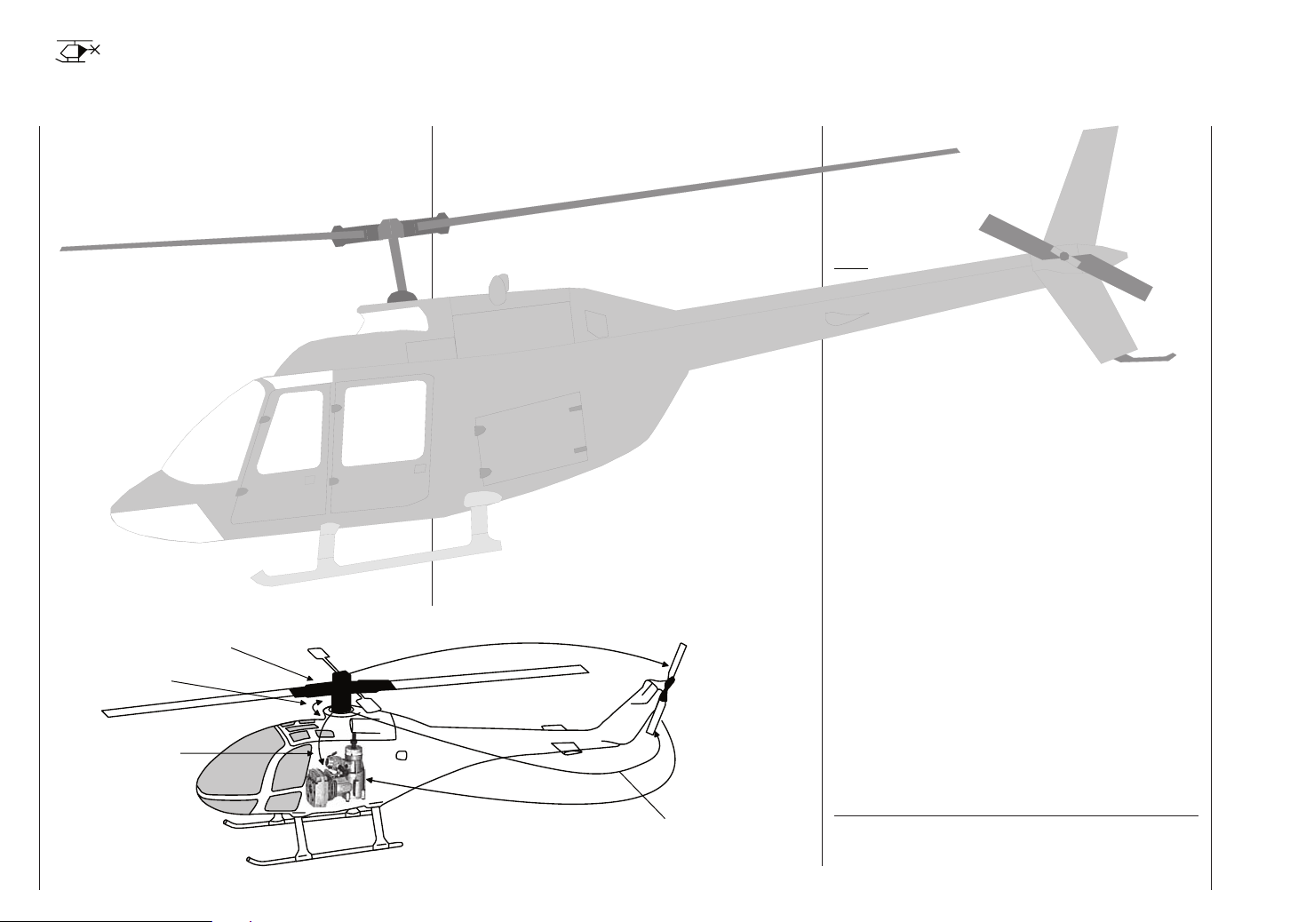
Model helicopters
The continued development of model helicopters and
helicopter components, such as gyros, speed governors, rotor blades etc., has led to the current position
where helicopters are capable of sophisticated 3-D aerobatics. In contrast, the beginner to helicopter fl ying
needs a simple set-up so that he can quickly get started
on the initial stages of hovering practice, and then gradually work up to more complex models which exploit all
the options provided by the mx-16s.
The helicopter program of the mx-16s can cope with all
current model helicopters equipped with 1...4 servos for
collective pitch control.
Each model memory can include two fl ight phases plus
autorotation.
Three timers are constantly included in the basic screen
display.
You can return to the correct idle position for the digital
C1 trim simply by pressing a button.
“Dual Rate” and “Exponential” are available for roll,
pitch-axis and tail rotor; they can be coupled together,
and programmed to provide two settings.
All the transmitter controls (CTRL) and switches (SW)
can be assigned to inputs 5 … 8 in virtually any order.
Collective
Pitch Curve
Swashplate
Rotation
Roll Õ Throttle
Pitch-Axis Õ Throttle
Channel 1 Õ Throttle
This is carried out in the »Control settings« menu.
The »Heli mixer« menu provides fi ve-point curves for
the collective pitch, throttle and tail rotor mixers, variable separately for each fl ight phase; these provide non-linear mixer characteristics. Such advanced features are
not needed by the beginner, who will initially simply set
the hover point to coincide with the centre point of stick
travel. The mixer inputs for collective pitch, roll and pitchaxis can then be adjusted in the »Swashplate mixers«
menu.
In addition to three linear mixers, which can be assigned
in any way you wish and can also be assigned a switch,
the »Heli mixer« menu also provides the following pre-
programmed mixers:
1. Collective pitch (with 5-point curve)
2. Ch1 throttle (with 5-point curve)
3. Ch1 tail rotor (with 5-point curve)
4. Gyro
The throttle limit function in the »Control settings«
menu provides an effective means of starting the motor in any fl ight phase. By default the proportional rotary
control CTRL 7 is assigned to this input, and this control function determines the maximum throttle servo posi-
R
ail
o
T
t
o
1
Õ
l
e
n
n
a
h
C
r
tion, i.e. the rotary knob controls the motor over the idle
range. If the rotary knob is turned in the direction of fullthrottle, the programmed throttle curves then take effect.
If you have set up the two timers, they also start recording the fl ight time automatically. See page 54 for more
information on this.
Note:
If you are fl ying a model helicopter fi tted with a PPM-FM
receiver made by another manufacturer*, which was previously fl own using another make of transmitter, e.g. for
Trainer mode operations, it may be necessary to re-arrange the receiver servo outputs as described on the
next page. However, an alternative method is to use the
»Receiver output« sub-menu of the »Base settings«
menu; see page 46. Different methods of installing servos and control linkages may make it necessary to reverse the direction of rotation of some servos when programming. In both cases this is carried out in the »Ser-
vo settings« menu; see page 48.
Note for modellers upgrading from earlier
GRAUPNER systems:
Compared with the previous receiver channel sequence,
servo socket 1 (collective pitch servo) and servo socket
6 (throttle servo) have been interchanged.
The servos must be connected to the receiver output sockets in the order shown on the next page.
Outputs not required are simply left vacant.
For more information on the different types of swashpla-
te, please refer to the »Base settings« menu described
on page 43.
Model helicopters
32
T
a
i
l
R
Õ
o
t
o
r
e
T
l
h
t
t
r
o
Roll Õ Tail Rotor
Pitch-Axis Õ Tail Rotor
Channel 1 Õ Tail Rotor
*
GRAUPNER does not guarantee that GRAUPNER radio control sys-
tems will work correctly in conjunction with receiving systems and
radio control equipment made by other manufacturers.
Page 33
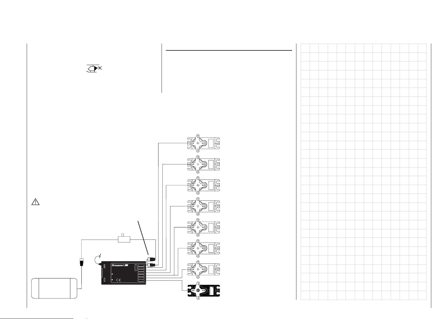
All menus which are relevant to model helicopters are
marked with a “helicopter” symbol in the “Program descriptions”:
This means that you can easily skip irrelevant menus
when programming a model helicopter.
Receiver socket assignment for model helicopters
Installation notes
The servos must be connected to the receiver outputs in the order shown on this page:
Outputs not required are simply left vacant.
Please note the additional information on the following pages.
8 = (Speed governor)
7 = (Gyro gain)
6 = Throttle servo (speed cont.)
WARNING
Do not shorten the aerial!
Receiver
battery
Switch harness
Receiver aerial
Y-lead, Order No.
3936.11 or 3936.32
Best.-Nr.
7
7052
S C A N
Made in Malaysia
6
8/Batt.
5
4
FM
! #
3
2
1
PLL-Synthesizer-MICRO-SUPERHET
Kanal 60-282/182-191
Antenne
R 1 6
für das 35MHz/35MHz-B-Band
SCAN LED
5 = Free, or pitch-axis (2) servo
4 = Tail rotor servo (gyro)
3 = Nick-axis (1) servo
2 = Roll-axis (1) servo
4,8 V
1 = Collective pitch or roll-axis
C 577
Servo
Best.-Nr. 4101
(2) or nick-axis (2) servo
Model helicopters – Installation and connections
33
Page 34
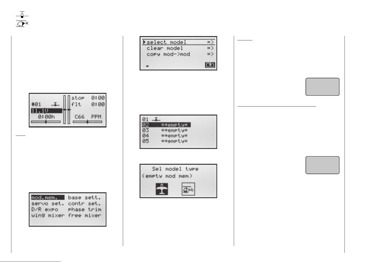
Detailed description of programming
Reserving a new memory
If you have already read through the manual to this point
you will undoubtedly have made your fi rst attempt at
programming the system already. Even so, it is important to describe each menu here in detail, to ensure that
you have comprehensive instructions for each application you are likely to encounter. On page 20 we have already explained how you move to the basic transmitter
display via Channel Select. In this section we start with
setting up a “empty” model memory prior to “programming” a new model:
Note:
You can adjust the screen contrast at any time by pressing the “+” or “-” button (right-hand rocker button) whilst
holding the SELECT button held in.
From the basic display press ENTER (left-hand rocker
button) to move to the “Multi-function list”. You can return
to the basic screen at any time by pressing ESC.
If necessary, select the »Model memory« menu from
the list using the right-hand rocker button, then press
ENTER or SELECT.
The model memories marked “empty” are not yet
in use. Memories which are already occupied appear
with the model name at the appropriate point, as entered in the »Base settings« menu (pages 38 and 42).
Use the right-hand rocker button to select one of the
empty model memories 1 to 12, then press ENTER or
SELECT.
You are now invited to select the basic model type, i.e.
either “Fixed-wing” or “Helicopter”.
Caution:
All the transmitter’s functions are barred, and the transmitter does not broadcast a signal, until you confi rm the
model type you have selected. If you switch off the transmitter before you set the model type, the screen will automatically switch to the Model Type Select display when
turned on again. You must always defi ne a model type!
• If the warning “Throttle too
high” appears on the screen,
move the throttle stick back in
the direction of idle.
Note for fi xed-wing models and helicopters:
This warning only appears in accordance with the settings you have entered in the “Motor” or “Collective pitch
min.” section of the »Base settings« menu, as described on pages 39 and 44. If you are setting up a non-powered fi xed-wing model, enter “none” at this point; this
disables the throttle warning message, and makes available the “Brake NN” mixers in the »Wing mixers»
menu, which would otherwise be suppressed.
• If the message “Set Fail-Safe”
appears on the screen, please
read the section describing the
»Fail-safe» menu on page 82..
throttle
too
high !
adjust
fail
safe !
Now press ENTER or SELECT again to move on to the
»Call up model« sub-menu.
Program description – Reserving a new memory
34
Use the right-hand rocker button to select the appropriate model type, then press ENTER or SELECT to confi rm
your choice. The screen switches back to the basic display: the model memory is now reserved.
It is now only possible to change this model memory to
a different model type if you fi rst erase the model memory (»Model memory« menu, page 36).
Page 35

Program description – Reserving a new memory
35
Page 36
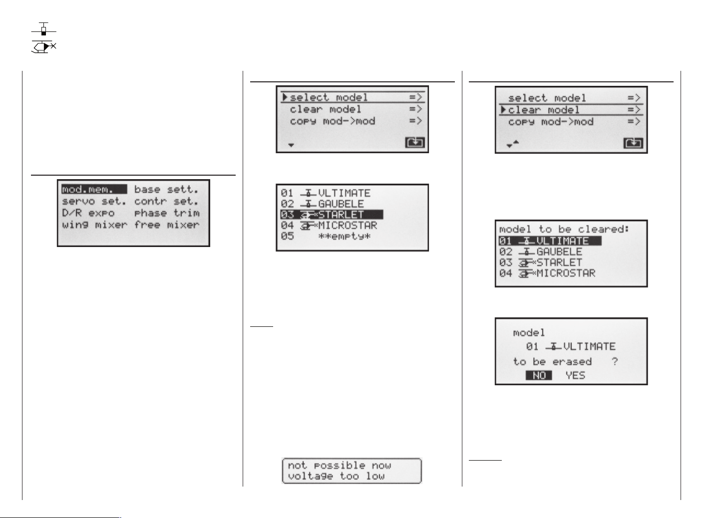
Model memories
Calling up a model, erasing a model, copying model model
The section on pages 18 and 19 explains the basic method of using the buttons, while the previous double page explains how to move to the Multi-function list
and reserve a new model memory. At this point we now
wish to start with the “normal” description of the individual menu points in the sequence in which they occur
on the transmitter itself. For this reason we start with the
menu …
Model memory
The transmitter can store up to 12 complete sets of model data, including the digital trim values set by the four
trim levers. The trims are automatically stored, which
means that the settings you have carefully established
through test-fl ying are not lost when you swap models. If
you have entered a model name in the »Base settings«
menu (pages 38 and 42), the name appears after the
model number.
Use the right-hand rocker button to select the »Model
memory« menu, and press ENTER or SELECT.
Select model
If you now press the ENTER or SELECT button again,
you move to the »Call up model« sub-menu:
Use the right-hand rocker button to select from the list
the model you wish to use, and confi rm your selection
by pressing ENTER or SELECT. Pressing ESC takes
you back to the previous menu page without switching
models.
Notes:
• If the warning message “Throttle too high” appears
when you switch models, the throttle stick (C1) is set
towards full throttle and should be moved back to
idle.
• If the message “Set Fail-Safe” appears when you
switch models, you should check your Fail-Safe settings. This only applies if the transmitter is set to
SPCM transmission mode.
• If the battery voltage is too low, it may not be possible
to switch model memories for safety reasons. In this
case the screen displays the following message:
Erasing a model
Hold the SELECT button pressed in, use the right-hand
rocker button to select the »clear model« sub-menu,
then press ENTER or SELECT.
Use the right-hand rocker button to select from the list
the model you wish to erase …
… then press SELECT or ENTER. The program responds with the security query: “model … to be erased?”
If you answer NO, the process is interrupted, and you
are returned to the previous screen page. If you answer
YES with the right-hand rocker button and confi rm your
choice with ENTER or SELECT, then the selected model memory is erased.
Caution:
The erasure process is irrevocable. All model memory data is reset to the factory default settings.
Program description – Model memories
36
Page 37
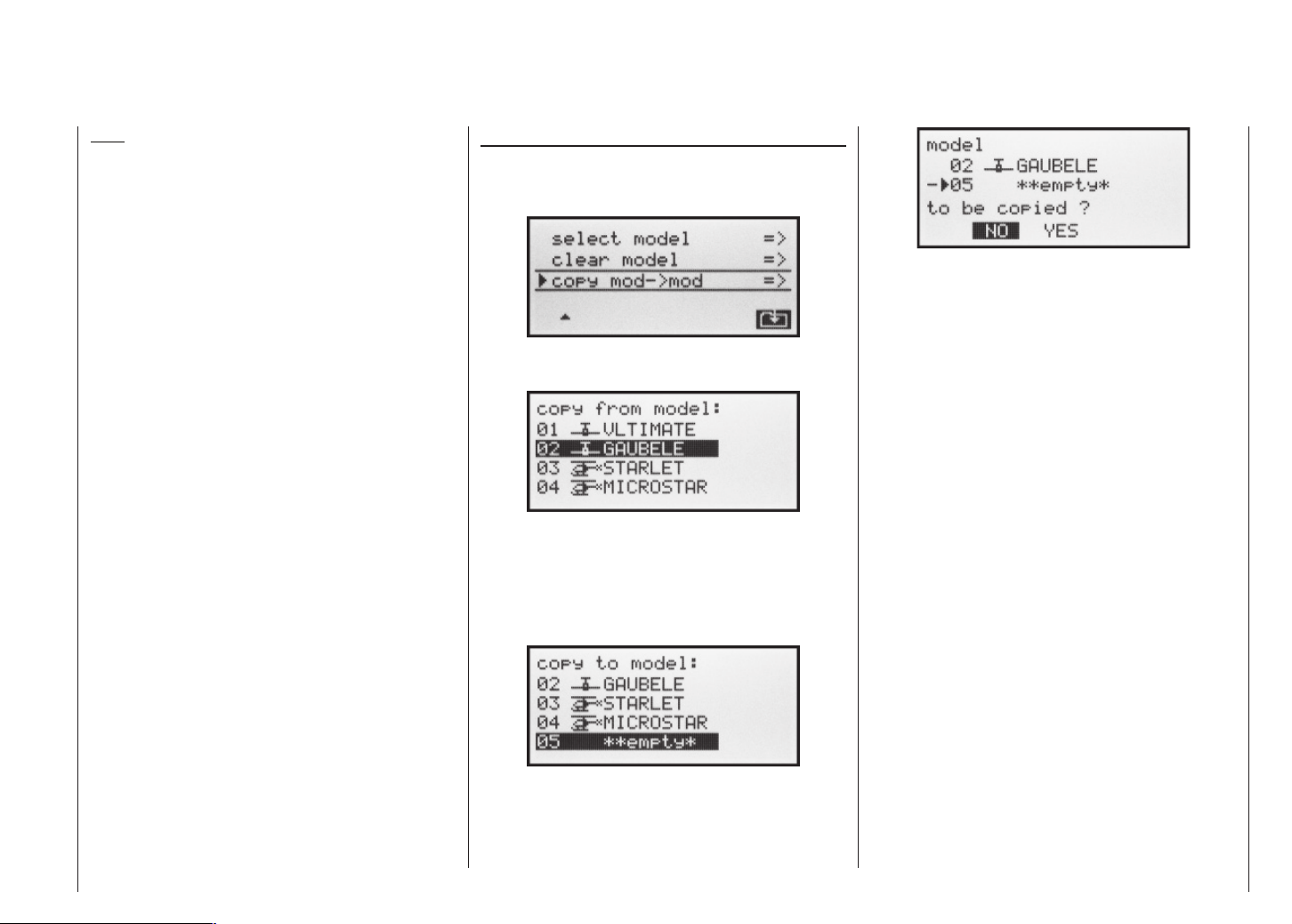
Note:
If you wish to erase the currently active model memory in the basic display, you will be required to defi ne the
model type “Heli” or “Fixed-wing” immediately. However,
if you erase a non-active model memory, then the message “**empty*” appears in the Model select menu.
Copy model model
Whilst holding the SELECT button pressed in, use the
right-hand rocker button to select the »Copy model
model« sub-menu, and press ENTER or SELECT:
Select the model to be copied using the right-hand rocker button …
... then press ENTER or SELECT again. In the »Copy
to model« window you can now select the target memory and confi rm your choice with ENTER or SELECT. Alternatively you can interrupt the process with ESC. It is
possible to overwrite a model memory which already
contains model data.
Selecting NO interrupts the process, and returns you
to the previous page. If you select YES with the righthand rocker button and confi rm your choice with ENTER
or SELECT, then the selected model is copied into the
chosen target model memory.
When you confi rm the selected model memory by pressing the ENTER or SELECT button, the security query
appears: ““model … … to be copied?”
Program description – Model memories
37
Page 38

Base settings
Basic model-specifi c settings for fi xed-wing model aircraft
Before you start programming specifi c parameters,
some basic settings must be entered which apply only
to the currently active model memory. Select the »Base
settings« menu with the right-hand rocker button, and
press ENTER or SELECT.
Model name
Press ENTER or SELECT to move to the next screen
page ( ), where you can select characters to assemble the model name. You can enter up to 9 characters to defi ne a model name.
Use the right-hand rocker button to select the fi rst character in the symbol fi eld. A short press on SELECT
moves to the next position in the name, at which point
you can again select a character. Pressing CLEAR inserts a space at that point.
You can move to any character position within the in-
put fi eld using the right-hand rocker button with the SE-
LECT button pressed in. The next space is indicated by
a double arrow <--> below the input fi eld while the SE-
LECT button is held pressed in.
The model name entered in this way appears in the
basic display, and also in the sub-menus of the »Model
memory« menu.
Stick mode
Basically there are four possible ways of arranging the
principal control functions of a fi xed-wing model on the
two dual-axis sticks: the primary functions are aileron,
elevator, rudder and throttle (or airbrakes) for a fi xedwing model. Which of these options you select depends
on your individual preferences and fl ying style.
»MODE 1« (Throttle at right stick)
elev. down
left rudder
elev. up
»MODE 3« (Throttle at right stick)
elev. down
left aileron
elev. up
right rudder
left aileron
right aileron
left rudder
full throttle
idle
Motor Vollgas
idle
»MODE 2« (Throttle at left stick)
full throttle
right aileron
left rudder
idle
»MODE 4« (Throttle at left stick)
full throttle
right rudder
left aileron
idle
right rudder
right aileron
elev. down
left aileron
elev. down
left rudder
right aileron
elev. up
right rudder
elev. up
When you select »stick mode« you will see SEL at the
bottom edge of the screen.
Press the SELECT button, and the current stick mode
is highlighted (inverse video – black background). Now
use the right-hand rocker button to select one of the options 1 to 4.
Pressing CLEAR resets the function to stick mode “1”.
Modulation
When you select »modulation« you will see SEL at the
bottom edge of the screen.
The mx-16s transmitter differentiates between two different types of modulation:
„SPCM“: Super PCM modulation with high system re-
solution of 1024 steps per control function,
for “smc” type receivers and up to 8 servos.
„PPM“: The most commonly used standard trans-
mission mode (FM or FMsss) for all other types of GRAUPNER PPM-FM receivers and
up to 8 servos.
Press the SELECT button. The current modulation is
highlighted (inverse video). Now use the right-hand rocker button to switch between the two possible modulations. The selected modulation is immediately active, i.e.
you can immediately test the signal transmission to the
receiver.
Pressing CLEAR switches to the “PPM” type of modulation.
Base settings – Fixed-wing model
38
Page 39
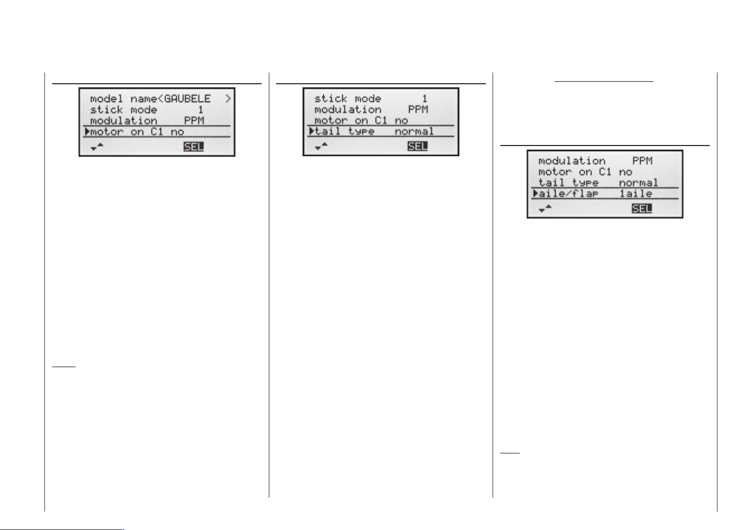
Motor at C1
Tail type
Note regarding “2 elev Sv”:
In this mode a transmitter control which
is assigned to input 8 in the »Control
settings« menu is de-coupled from servo
“8”; this is for safety reasons.
Ailerons / Camber-changing fl aps
When you select »motor at C1« you will see SEL at the
bottom edge of the screen. Press the SELECT button.
The current setting is highlighted. Now use the righthand rocker button to switch between the three possible options:
„no“: The throttle warning message
“Throttle too high” is disabled
(see page 18 or 34). In the »Wing
mixer« menu the “Brake NN”
mixers are activated.
„Idle re.“: The idle position of the throttle / air-
brake stick (C1) is rear, i.e. towards
the pilot.
„Idle fr.“: The idle position of the throttle / air-
brake stick (C1) is in front, i.e. away
from the pilot.
Notes:
• Note that the “Brake NN” mixers in the »Wing mi-
xer« menu are suppressed if you select “Idle front” or
“Idle rear”.
• Depending on your choice in this menu, the C1 trim
acts “normally” (over the full control travel), or just
at the idle end of the range, i.e. only at the “rear” or
“front” end of the stick travel.
• “Cut-off trim”: this special function is described on
page 26.
When you select »tail type« you will see SEL at the bottom edge of the screen. Press the SELECT button. The
current setting is highlighted. Now use the right-hand rocker button to select the option which matches your model:
„normal“: This setting caters for all models in which
each of the functions elevator and rudder
is operated by one servo.
„V-tail“: The elevator and rudder controls are
operated by two control surfaces set in a
V-shape, each controlled by a separate
servo. The two-way coupling function for
the rudder and elevator control systems is
automatically carried out by the program.
If necessary, the ratio of rudder travel
to elevator travel can be adjusted in the
»Dual Rate« menu (page 56).
„Delt/FlW“: The mixed elevon (aileron and elevator)
control system requires two or four separate servos, one or two in each wing.
However, the elevator trim only affects
servos 2 + 3, even if you select “2AIL 2FL”
– see right-hand column.
„2 elev sv“: This option is designed for model aircraft
with two elevator servos. When the elevator stick is moved, the servo connected
to receiver output 8 moves in parallel with
servo 3. The elevator trim lever affects
both servos.
When you select the »Aileron / Flap« line you will see
SEL at the bottom edge of the screen. Press the SELECT button, and the current setting is highlighted. Now
use the right-hand rocker button to select one of the
three options:
„1aile“ Both ailerons are actuated by a single
servo.
„2aile“ Each aileron is actuated by a separate
servo.
„2ail2fl “ Each aileron is actuated by a separate
servo; there are also one or two camberchanging fl ap servos.
The mixers and associated adjustment facilities which
appear in the »Wing mixers« menu (see section star-
ting on page 61) vary according to the data you enter
here. The software provides a maximum of 12 readymade mixers for up to two aileron servos and two camber-changing fl ap servos.
Note:
If your model is equipped with only one fl ap servo, you
should still select “2ail 2fl ”, but leave the “AIL FL” mixer in the »Wing mixer« menu (see page 61) at 0%. In
Base settings – Fixed-wing model
39
Page 40
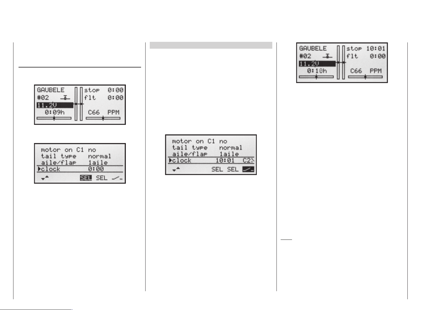
contrast, all the other wing mixers can be used in the
usual way.
Clocks
Two timers are shown in the basic display: one stopwatch and one fl ight timer.
You can assign a physical switch or a control switch to
these two timers in the »clock« line …
… using the switch symbol on the right-hand side. The
assigned switch starts both timers, and also halts the
stopwatch.
The method of assigning a physical switch or a control
switch is described on page 25.
The fl ight timer always starts simultaneously with the
stopwatch, but continues to run even when the stopwatch is halted (switched off). It can only be stopped by
pressing ESC with the stopwatch halted.
Once stopped, both timers can be reset to the initial value using CLEAR.
Switching between “count-up” and “count-down”
Count-up timer (stopwatch function)
If you assign a switch and start the stopwatch with the
initial value of “0:00”, the timer runs up until the maximum of 999 minutes and 59 seconds, then re-starts at
0:00.
Count-down timer (timer function)
You can use the left-hand SEL fi eld to select a starting
time within the range 0 to 180 minutes; using the righthand SEL fi eld the range is 0 to 59 seconds. Any combination of times can also be selected.
( CLEAR = „0“ or „00“.)
Procedure
1. Select the SEL fi eld with the right-hand rocker button.
2. Press SELECT.
3. Select the required time in the highlighted minutes
and seconds fi elds using the right-hand rocker button.
4. Press SELECT to conclude the input process.
Once you have entered the settings described above,
the set value is shown in the basic display (see picture in right-hand column), e.g. as 10:01 in min : sec. If the
display in the “Stop” line of the basic display does not
agree with your settings, press the CLEAR button.
When you operate the assigned switch, the stopwatch
now starts from the set initial value, counting down (“Timer function”). When the set time has elapsed, the timer does not stop, but continues to run to allow you to
read off the time elapsed after reaching zero. To make
this clear, the over-run time is shown highlighted (inverse video).
Sequence of sounds
30 sec. before zero: triple beep
single beep every two seconds
20 sec. before zero: double beep
single beep every two seconds
10 sec. before zero: single beep
single beep every second
5 sec. before zero: single beep every second at
higher rate
zero: longer beep; display switches to
inverse video
The “alarm timer” is reset by pressing the CLEAR button
after you have halted the timer.
Note:
A count-down timer is indicated in the basic display by a
fl ashing colon (:) between the minutes fi eld and the seconds fi eld.
Base settings – Fixed-wing model
40
Page 41
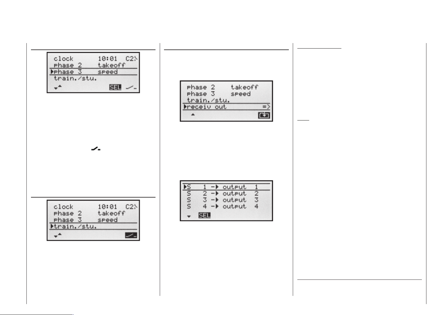
Phase 2 / Phase 3
When you select »Phase 2« or »Phase 3«, you will see
SEL at the bottom edge of the screen. Press the SELECT button, and the current setting is shown highligh-
ted. If you do not wish to use the default names, use
the right-hand rocker button to select a suitable name
from the pre-sets. Press SELECT to return to the function line.
Move to the switch symbol using the right-hand rocker button, then press SELECT again. A switch can be
assigned to the fl ight phase as described on page 25.
For more information on fl ight phase programming please refer to page 60, in the section entitled »Phase
trim«.
Trainer / Student
Receiver output
For maximum fl exibility in terms of receiver socket assignment, the mx-16s program provides the means to
swap over the servo outputs 1 to max. 8; this is carried
out on the second page of the »Receiv out.« sub-menu.
Press the SELECT or ENTER button to move to the
next page of the display. Here you can assign the “control channels” for servos 1 … 8 to any receiver output you wish to use. However, please note that the display in »Servo display« – which you can reach by pressing SELECT from the basic display – refers exclusively
to the “control channels”, i.e. the outputs are not swapped over.
Typical applications:
• If you wish to use a smaller receiver with six or even
just four servo sockets, it may be necessary to swap
over the receiver sockets in order to be able to operate a second camber-changing fl ap, a second aileron
servo or a speed controller.
• It may also prove necessary to swap servos for Trainer mode operations, if you are using a model set up
for another make * of equipment, to avoid having to
re-connect the servos at the receiver.
Note:
Please note that the Fail-safe “hold-mode” and “position”
programming in SPCM mode always affect the “outputs”,
i.e. the receiver socket numbers; this still applies if you
swap the receiver outputs.
In this menu line you can assign a “transfer switch” for
Trainer (teacher / pupil) mode operations, after pressing
SELECT or ENTER, as described on page 25.
For more information on Trainer systems please refer to
page 110.
With the SELECT button held pressed in, use the righthand rocker button to select the servo / output combination you wish to change, then press ENTER or SELECT.
Now you can assign the desired servo(s) to the selected
output using the right-hand rocker button … or alternatively press CLEAR to revert to the default sequence.
Please note that any changes to servo settings, such
as servo travel, Dual Rate / Expo, mixers etc., must be
carried out according to the original (default) receiver socket sequence.
*
GRAUPNER does not guarantee that GRAUPNER radio control sys-
tems will work correctly in conjunction with receiving systems and
radio control equipment made by other manufacturers.
Base settings – Fixed-wing model
41
Page 42

Base settings
Basic model-specifi c settings for fi xed-wing model aircraft
Before you start programming specifi c parameters,
some basic settings must be entered which apply only
to the currently active model memory. Select the »Base
settings« menu with the right-hand rocker button, and
press ENTER or SELECT.
Model name
Press ENTER or SELECT to move to the next screen
page ( ), where you can select characters to assemble the model name. You can enter up to 9 characters to defi ne a model name.
Use the right-hand rocker button to select the fi rst character in the symbol fi eld. A short press on SELECT
moves to the next position in the name, at which point
you can again select a character. Pressing CLEAR inserts a space at that point.
You can move to any character position within the in-
Base settings – Model helicopter
42
put fi eld using the right-hand rocker button with the SE-
LECT button pressed in. The next space is indicated by
a double arrow <--> below the input fi eld while the SE-
LECT button is held pressed in.
The model name entered in this way appears in the
basic display, and also in the sub-menus of the »Model
memory« menu point.
Stick mode
Basically there are four possible ways of arranging the
principal control functions of a model helicopter on the
two dual-axis sticks: the primary functions are roll, pitchaxis, tail rotor and throttle / collective pitch. Which of these options you select depends on your individual preferences and fl ying style.
»MODE 1« (Throttle at right stick)
pitch axis
tail rotor
pitch axis
»MODE 3« (Throttle at right stick)
pitch axis
roll
pitch axis
throttle
tail rotor
roll
throttle throttle
Motor/Pitch
roll
tail rotor
throttle
»MODE 2« (Throttle at left stick)
throttle
tail rotor
throttle
roll
throttle
tail rotor
roll
roll
»MODE 4« (Throttle at left stick)
tail rotor
pitch axis
roll
pitch axis
pitch axis
tail rotor
pitch axis
roll
tail rotor
When you select »stick mode« you will see SEL at the
bottom edge of the screen.
Press the SELECT button, and the current stick mode
is highlighted (inverse video – black background). Now
use the right-hand rocker button to select one of the options 1 to 4.
Pressing CLEAR resets the function to stick mode “1”.
Modulation
When you select »modulation« you will see SEL at the
bottom edge of the screen.
The mx-16s transmitter differentiates between two different types of modulation:
„SPCM“: Super PCM modulation with high system re-
solution of 1024 steps per control function,
for “smc” type receivers and up to 8 servos.
„PPM“: The most commonly used standard trans-
mission mode (FM or FMsss) for all other types of GRAUPNER PPM-FM receivers and
up to 8 servos.
Press the SELECT button. The current modulation is
highlighted (inverse video). Now use the right-hand rocker button to switch between the two possible modulations. The selected modulation is immediately active, i.e.
you can immediately test the signal transmission to the
receiver.
Pressing CLEAR switches to the “PPM” type of modulation.
Page 43
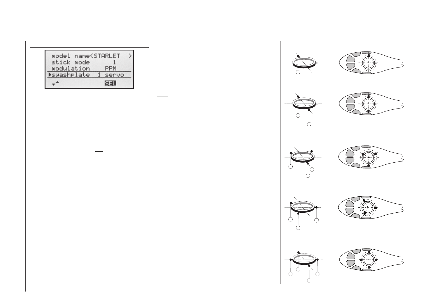
Swashplate type
You will require a particular program variant to suit the
number of servos which operate the collective pitch
function. Press the SELECT button.
The current number of collective pitch servos is highlighted on the screen. You can now determine the required
variant using the right-hand rocker button:
„1 servo“: The swashplate is tilted by one roll servo
and one pitch-axis servo. Collective pitch
is controlled by one separate servo.
(The »Swashplate mixer« menu point
is suppressed in the multi-function menu
if you select “1 servo” as the swashplate
type. This is because model helicopters
with only one collective pitch servo are
controlled without transmitter mixers for
the swashplate functions collective pitch,
pitch-axis and roll.)
„2 servo“: The swashplate is moved axially by two
roll servos for collective pitch control;
pitch-axis control is de-coupled by a mechanical compensating rocker (HEIM
mechanics).
„3sv (2roll)“: A symmetrical three-point swashplate lin-
kage using three linkage points arranged
equally at 120°, actuated by one pitchaxis servo (front or rear) and two roll servos (left and right). For collective pitch
control all three servos move the swashplate axially.
„3Sv (2nick)“: A symmetrical three-point linkage as
above, but rotated through 90°, i.e. one
roll servo on one side, and two pitch-axis
servos front and rear.
„4Sv (90°)“: Four-point swashplate linkage using two
roll and two pitch-axis servos.
CLEAR resets the swashplate type to “1 servo”.
Note:
The swashplate mixer ratios are set in the »Swashpla-
te mixers« menu.
Swashplate type: 1 servo
2
Swashplate type: 2 servos
2
1
Swashplate type: 3 servos (2 nick)
1
3
2
Swashplate type: 3 servos (2 roll)
2
1
3
Swashplate type: 4 servos (90°) 2 nick / 2 roll
2
5
3
1
Base settings – Model helicopter
43
Page 44

(Main-) Rotor direction
In the »rotor direction« line you enter the direction of rotation of the main rotor using the right-hand rocker button, after pressing SELECT:
„right“: the main rotor rotates clockwise as viewed
from above.
„links“: the main rotor rotates anti-clockwise as view-
ed from above.
CLEAR switches to “left”.
Collective pitch min.
At this point you can set up the direction of operation of
the throttle / collective pitch stick to suit your preference:
Press SELECT, then use the right-hand rocker button to
select the appropriate setting. This setting is crucial to
the correct operation of all the other options in the helicopter program which affect the throttle and collective pitch function, i.e. the throttle curve, idle trim, tail rotor mixer etc..
Collective pitch
Note:
• The C1 trim always affects the throttle servo only.
• By default what is known as the “throttle limiter” is set
(see page 54); this limits the travel of the throttle servo in the direction of maximum throttle, acting separately from the collective pitch servos. This point can
be programmed using the “Lim” input in the »Control
settings« menu.
Clocks
Two timers are shown in the basic display: one stopwatch and one fl ight timer.
A physical switch or a control switch can be assigned to
these two timers in the “Timers” line …
right-hand
rotation
left-hand
rotation
The program requires this information in order to set up
the mixers to work in the correct “sense”; this applies to
the mixers which compensate for rotor torque and motor
power. You will fi nd these in the »Heli mixer« menu:
Collective pitch
Channel 1 throttle
Channel 1 tail rotor
Base settings – model helicopter
44
The meaning is as follows:
“front”: minimum collective pitch when the collective
pitch stick (C1) is in “front” (away from you);
“rear”: minimum collective pitch when the collective
pitch stick (C1) is “back” (towards you).
Pressing CLEAR sets the collective pitch min. position
to “front”.
… using the switch symbol on the right-hand side. The
assigned switch starts both timers, and also halts the
stopwatch.
The method of assigning a physical switch or a control
switch is described on page 25.
The fl ight timer always starts simultaneously with the
stopwatch, but continues to run even when the stopwatch is halted (switched off). It can only be stopped by
pressing ESC with the stopwatch halted.
Page 45

Once stopped, both timers can be reset to the initial value using CLEAR.
Switching between “count-up” and “count-down”
Count-up timer (stopwatch function)
If you assign a switch and start the stopwatch with the
initial value of “0:00”, the timer runs up until the maximum of 999 minutes and 59 seconds, then re-starts at
0:00.
Count-down timer (timer function)
You can use the left-hand SEL fi eld to select a starting
time within the range 0 to 180 minutes; using the righthand SEL fi eld the range is 0 to 59 seconds. Any combination of times can also be selected.
( CLEAR = „0“ or „00“.)
Procedure
1. Select the SEL fi eld with the right-hand rocker button.
2. Press SELECT.
3. Select the required time in the highlighted minutes
and seconds fi elds using the right-hand rocker button.
4. Press SELECT to conclude the input process.
Once you have entered the settings described above,
the set value is shown in the basic display (see picture in right-hand column), e.g. as 10:01 in min : sec. If the
display in the “Stop” line of the basic display does not
agree with your settings, press the CLEAR button.
When you operate the assigned switch, the stopwatch
now starts from the set initial value, counting down (“Timer function”). When the set time has elapsed, the timer does not stop, but continues to run to allow you to
read off the time elapsed after reaching zero. To make
this clear, the over-run time is shown highlighted (inverse video).
Sequence of sounds
30 sec. before zero: triple beep
single beep every two seconds
20 sec. before zero: double beep
single beep every two seconds
10 sec. before zero: single beep
single beep every second
5 sec. before zero: single beep every second at
higher rate
zero: longer beep; display switches to
inverse video
The “alarm timer” is reset by pressing the CLEAR button
after you have halted the timer.
Note:
A count-down timer is indicated in the basic display by a
fl ashing colon (:) between the minutes fi eld and the seconds fi eld.
Phase 2
In the »phase 2« line you use the SEL fi eld to select
a suitable name from the six default names provided,
using the right-hand rocker button. You can also assign a
switch using the switch symbol at bottom right.
Autorotation
The name “autorotat.” is permanently assigned to Phase 3, and cannot be altered. The only available option is
to assign a switch to it using the switch symbol at bottom
right of the screen.
For more information on programming the fl ight phases please refer to the »Heli mixer« section starting on
page 66.
Note:
The “autorotation” fl ight phase ALWAYS has precedence
over all other fl ight phases.
Base settings – Model helicoptert
45
Page 46

Trainer / student
In this menu line you can assign a “transfer switch” for
trainer (trainer / student) mode operations, after pressing SELECT or ENTER, as described on page 25.
For more information on Trainer systems please refer to
page 110.
Receiver output
For maximum fl exibility in terms of receiver socket assignment, the mx-16s program provides the means to
swap over the servo outputs 1 to max. 8; this is carried
out on the second page of the »receiver output« submenu.
Press the SELECT or ENTER button to move to the
next page of the display. Here you can assign the “control channels” for servos 1 … 8 to any receiver output you wish to use. However, please note that the display in »Servo display« – which you can reach by pressing SELECT from the basic display – refers exclusively
to the “control channels”, i.e. the outputs are not swapped over.
With the SELECT button held pressed in, use the righthand rocker button to select the servo / output combina-
Base settings – Model helicopter
46
tion you wish to change, then press ENTER or SELECT.
Now you can assign the desired servo(s) to the selected
output using the right-hand rocker button … or alterna-
tively press CLEAR to revert to the default sequence.
Please note that any changes to servo settings, such
as servo travel, Dual Rate / Expo, mixers etc., must be
carried out according to the original (default) receiver socket sequence.
Typical applications:
• In the helicopter program of the mx-16s the outputs
for one collective pitch servo and the throttle servo have been interchanged compared to all earlier
GRAUPNER/JR mc-systems. The throttle servo is
now assigned to receiver output “6” and the collective pitch servo to output “1”. You may therefore wish to
retain the earlier confi guration.
• It may also prove necessary to swap servos for Trainer mode operations, if you are using a model set up
for another make * of equipment, to avoid having to
re-connect the servos at the receiver.
*
GRAUPNER does not guarantee that GRAUPNER radio control sys-
tems will work correctly in conjunction with receiving systems and
radio control equipment made by other manufacturers.
Note:
Please note that the Fail-safe “hold-mode” and “position”
programming in SPCM mode always affect the “outputs”,
i.e. the receiver socket numbers; this still applies if you
swap the receiver outputs.
Page 47

Base settings – Model helicopter
47
Page 48
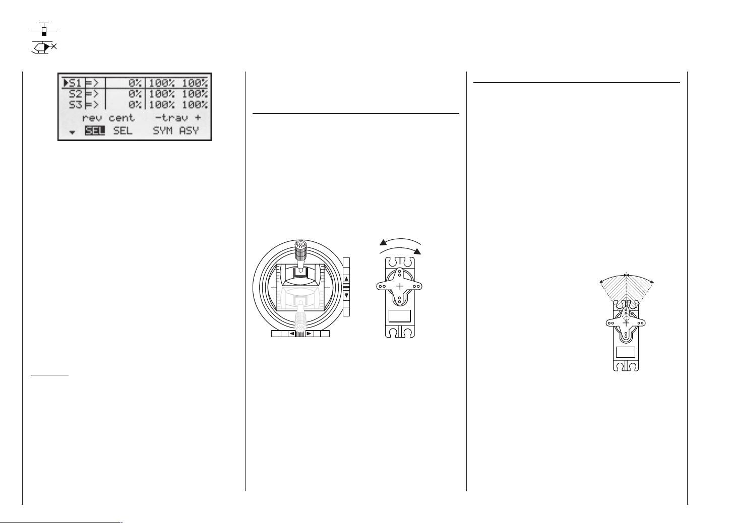
Servo settings
Servo direction, centre, travel
In this menu you can adjust parameters which only affect the servo connected to a particular receiver output,
namely the direction of servo rotation, neutral point and
servo travel. Always start with the servo setting in the
left-hand column.
Basic procedure:
1. Hold the SELECT button pressed in and select the
relevant servo (1 to 8) using the right-hand rocker
button.
2. Use the right-hand rocker button to select SEL, SYM
or ASY in the bottom line, prior to making the adjustments required.
3. Press the SELECT button: the corresponding input
fi eld is highlighted (inverse video).
4. Set the appropriate value using the right-hand rocker
button.
5. Finally press the SELECT button again to conclude
the input process.
Important:
The numbers in the servo designations refer to the receiver output socket to which a particular servo(s) is
connected. These numbers do not necessarily coincide
with the numbering of the transmitter control function inputs, and indeed any coincidence would be purely accidental. The sophisticated programs of the mx-16s mean
that the numbers are unlikely to be the same in any
case. For example, changing the stick mode does not
affect the numbering (i.e. receiver socket sequence) of
the servos. The same applies to any changes you make
in the servo sequence in the »Receiver output« menu
(see pages 41 and 46).
Column 2 “reverse”
The direction of servo rotation can be adjusted to suit
the actual installation in your model. This means that
you don’t need to concern yourself with servo directions
when installing the mechanical linkages in the model, as
you can reverse them as and when necessary. The direction of rotation is indicated by the symbols “=>” and
“<=”. Be sure to set the direction of servo rotation before
you make adjustments to the remaining options!
Pressing CLEAR resets the direction of rotation to “=>”.
normal
normal
reversed
reversed
Column 3 “centre”
The facility to offset the servo travel centre is intended
for adjusting servos whose centre setting is not standard
(servo centre point at 1.5 ms), and also for minor adjustments, e.g. when fi ne-tuning the neutral position of the
model’s control surfaces.
The neutral position can be shifted within the range
-125% to +125% of normal servo travel, regardless of
the trim lever position and any mixers you have set up.
The centre setting affects the associated servo directly,
independently of all other trim and mixer settings. However, please note that an extreme shift of the servo’s neutral point may result in servo travel to one side of neutral
only, as total servo travel is limited to +/-150% for both
electronic and mechanical reasons.
Pressing CLEAR resets the value to “0%”.
0 0
-125% +125%
Servo travel
centre adjustment
Servo settings
48
Page 49

Column 4 “- travel +”
In this column you can adjust servo travel symmetrically or asymmetrically (different each side of neutral). The
adjustment range is 0 ... +150% of normal servo travel.
The reference point for the set values is the setting in
the “Centre” column.
To set a “symmetrical” travel, i.e. to adjust travel equally
on both sides of neutral, select SYM; select ASY to set
asymmetrical travel. In the latter case move the associated transmitter control (stick, proportional rotary knob or
switch) to the appropriate end-point; when you press the
SELECT button the highlighted servo travel fi eld switches between the left fi eld (negative direction) and the
right fi eld (positive direction).
Pressing CLEAR resets the changed parameter to
100%.
Important:
In contrast to the »Control settings« menu this setting
affects the servo directly, regardless of how the control
signal for this servo is generated, i.e. either directly by a
stick channel, or by means of any type of mixer function.
1 5 0
%
1 0 0
8 0
Servo travel
6 0
4 0
2 0
0
The graph alongside
shows an example of
asymmetrical servo
travel, with a setting of
-50% and +150%.
0 2 0 4 0 6 0 8 0 1 0 0 %
Transmitter control travel
Servo settings
49
Page 50
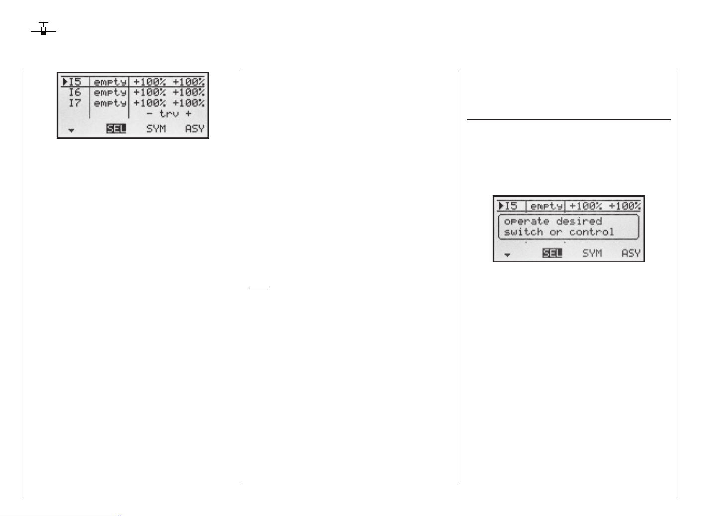
Control settings
Basic procedures for assigning transmitter controls and switches
In addition to the two dual-axis stick units for the control
functions 1 to 4, the mx-16s is fi tted as standard with a
range of supplementary controls:
• Two INC / DEC buttons: CTRL 5 and 6 (“transmitter
controls 5 … 6”)
• One three-position switch: SW 6/7 (assigned to “Control 8” in this menu)
• One rotary proportional knob: CTRL 7 (“transmitter
control 7”)
• One push-button: SW 4 / PB 8 (“SW 4” or “SW 8”)
• Three two-position switches: SW 1 to SW 3 (“SW1 …
3”)
The two dual-axis stick units directly affect the servos
connected to receiver outputs 1 … 4 (assuming that you
have set up a newly initialised model memory with the
model type “Fixed-wing model”). In contrast, the “supplementary” transmitter controls listed above are inactive
when the transmitter is in its default state (as delivered).
As already mentioned on page 14, this means that the
transmitter in its basic form only controls servos connected to receiver outputs 1 … 4 using the primary sticks
– even when you have initialised a new model memory with the model type “fi xed-wing model”. Any servos
connected to receiver sockets 5 … 8 simply stay at their
centre point when you operate the associated transmitter controls.
This may seem rather inconvenient at fi rst sight, but it
is the only way to ensure that you can select any of the
“supplementary” transmitter controls for any task you
like, and that you are not required deliberately to “program away” the transmitter controls which are not required for a particular model.
Unless it is inactive, any superfl uous transmitter
control will have an effect on your model if you operate it by mistake, i.e. unless you have assigned no
function to it.
That is why you can select these “supplementary” transmitter controls with complete freedom in the “Control
settings” menu and assign them to any function input
(see page 24) you like, as this method means that the
transmitter meets your own requirements exactly. This
also means that each of these transmitter controls can
be set to operate several function inputs simultaneously. For example, the same toggle switch SW X which you
assign to an input in this menu, can also be assigned
as the On / OFF switch controlling the “Timers” in the
»Base settings« menu.
Note:
If you switch models, the current positions of the INC /
DEC buttons (CTRL 5 + 6) assigned to inputs 5 … 8 are
stored separately for each memory, i.e. the settings are
not lost.
Basic procedure
1. Hold the SELECT button pressed in, and select the
appropriate input E5 … E8 using the right-hand rocker button.
2. Use the right-hand rocker button to select SEL, SYM
or ASY so that you can carry out the adjustments
you wish to make.
3. Press the SELECT button: the input fi eld you wish to
modify is highlighted.
4. Operate the transmitter control you wish to use, and
set the desired value using the right-hand rocker button.
5. Press the SELECT button to conclude the input pro-
cess and return to the function fi eld.
Column 2 “Assigning transmitter controls and switches”
Hold the SELECT button pressed in, and select one of
the function inputs 5 to 8 using the right-hand rocker
button.
Use the right-hand rocker button to select SEL, or (if
SEL is already highlighted) press the SELECT button to
move to the assignment facility …
… and move the appropriate transmitter control (CTRL
5 to 7), or operate the selected switch (SW 1 to 4, 6/7,
8). Note that the transmitter emits a “beep” when it detects the two INC / DEC buttons (CTRL 5 and 6) and the
rotary proportional control, i.e. they need to be operated
for longer than the other controls. If the travel is not suffi cient for the transmitter to detect it, move the control in
the opposite direction.
If you assign one of the two-position switches, then this
control channel works like an On / Off switch. It is then
possible to switch to and fro between two end-point values using this simple switch, e.g. motor ON / OFF. The
three-position switch SW 6/7, which you will fi nd in the
»Control settings« menu as “Control 8”, also provides
a centre position.
Pressing the CLEAR button with the switch assignment
activated – see illustration above – resets the input to
“free”.
Control settings – Fixed-wing model
50
Page 51

Tips:
When assigning the switches please take care to set
them to the appropriate direction of travel, and ensure that all inputs not required are left at or set to “free”,
to eliminate the possibility of errors if unused transmitter
controls are operated accidentally.
You can alter the effective end-points of an assigned
switch by adjusting servo travel as described in the next
section.
After you have assigned an external switch, the screen
displays either the transmitter control number or the
switch number, followed by a switch symbol which indicates the direction of operation, e.g.:
Column 3 “-Travel+”
Hold the SELECT button pressed in, and use the righthand rocker button to select one of the inputs 5 to 8.
Use the right-hand rocker button to select SYM or ASY
in the “-Travel+” column, and press the SELECT button
to activate travel adjustment:
You can now use the right-hand rocker button to set the
control travel within the range -125% to +125%, either
symmetrically (SYM) to both sides, or asymmetrically
(ASY). At the same time you can use the software to reverse the direction of effect of the transmitter control. If
you wish to make asymmetrical adjustments, you must
move the transmitter control or switch in the appropriate direction before altering the setting. When the fi eld is
highlighted, you can change the setting.
Pressing CLEAR resets the control travel in the highlighted fi eld to 100%.
Important:
In contrast to servo travel adjustments, changing the
transmitter travel setting affects all mixer and coupling
inputs, i.e. all servos which are affected by that transmitter control.
Control settings – Fixed-wing model
51
Page 52
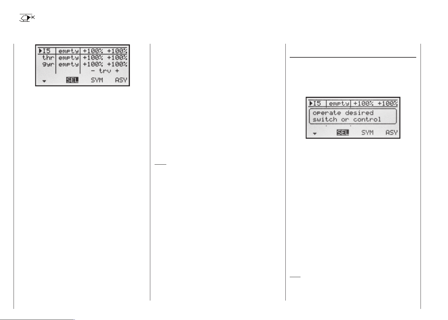
Control settings
Basic procedures for assigning transmitter controls and switches
In addition to the two dual-axis stick units for the control
functions 1 to 4, the mx-16s is fi tted as standard with a
range of supplementary controls:
• Two INC / DEC buttons: CTRL 5 and 6 (“transmitter
controls 5 … 6”)
• One three-position switch: SW 6/7 (assigned to “Control 8” in this menu)
• One rotary proportional knob: CTRL 7 (“transmitter
control 7”)
• One push-button: SW 4 / PB 8 (“SW 4” or “SW 8”)
• Three two-position switches: SW 1 to SW 3 (“SW1 …
3”)
The two dual-axis stick units directly affect servos connected to receiver outputs 1 … 4 (assuming that you
have set up a newly initialised model memory with the
model type “Helicopter”). In contrast, the “supplementary” transmitter controls listed above are inactive when
the transmitter is in its default state (as delivered).
As already mentioned on page 14, this means that the
transmitter in its basic form only controls servos connected to receiver outputs 1 … 4 using the primary sticks.
Any servos connected to receiver sockets 5 … 8 simply
stay at their centre point when you operate the associated transmitter controls.
This may seem rather inconvenient at fi rst sight, but it
is the only way to ensure that you can select any of the
“supplementary” transmitter controls for any task you
like, and that you are not required deliberately to “program away” the transmitter controls which are not re-
quired for a particular model.
Unless it is inactive, any superfl uous transmitter
control will have an effect on your model if you operate it by mistake, i.e. unless you have assigned no
function to it.
That is why you can select these “supplementary” transmitter controls with complete freedom in the “Control
settings” menu and assign them to any function input
(see page 24) you like, as this method means that the
transmitter meets your own requirements exactly. This
also means that each of these transmitter controls can
be set to operate several function inputs simultaneously. For example, the same toggle switch SW X which you
assign to an input in this menu, can also be assigned
as the On / OFF switch controlling the “Timers” in the
»Base settings« menu.
Note:
If you switch models, the current positions of the INC /
DEC buttons (CTRL 5 + 6) assigned to inputs 5 … 8 are
stored separately for each memory, i.e. the settings are
not lost.
Basic procedure
1. Hold the SELECT button pressed in, and select the
appropriate input E5 … E8 using the right-hand rocker button.
2. Use the right-hand rocker button to select SEL, SYM
or ASY so that you can carry out the adjustments
you wish to make.
3. Press the SELECT button: the input fi eld you wish to
modify is highlighted.
4. Operate the transmitter control you wish to use, and
set the desired value using the right-hand rocker button.
5. Press the SELECT button to conclude the input pro-
cess and return to the function fi eld.
Column 2 “Assigning transmitter controls and switches”
Hold the SELECT button pressed in, and select one of
the inputs using the right-hand rocker button.
Use the right-hand rocker button to select SEL, or (if
SEL is already highlighted) press the SELECT button to
move to the assignment facility …
… and move the appropriate transmitter control (CTRL
5 to 7), or operate the selected switch (SW 1 to 4, 6/7,
8). Note that the transmitter emits a “beep” when it detects the two INC / DEC buttons (CTRL 5 and 6) and the
rotary proportional control, i.e. they need to be operated
for longer than the other controls. If the travel is not suffi cient for the transmitter to detect it, move the control in
the opposite direction.
If you assign one of the two-position switches, then this
control channel works like an On / Off switch. It is then
possible to switch to and fro between two end-point values using this simple switch, e.g. searchlight ON / OFF.
The three-position switch SW 6/7, which you will fi nd in
the »Control settings« menu as “Control 8”, also provides a centre position.
Pressing the CLEAR button with the switch assignment
activated – see illustration above – resets the input to
“free”.
Tips:
When assigning the switches please take care to set
them to the appropriate direction of travel, and ensure that all inputs not required are left at or set to “free”,
Control settings – Model helicopter
52
Page 53

to eliminate the possibility of errors if unused transmitter
controls are operated accidentally.
You can alter the effective end-points of an assigned
switch by adjusting servo travel as described in the next
section.
After you have assigned an external switch, the screen
displays either the transmitter control number or the
switch number, followed by a switch symbol which indicates the direction of operation, e.g.:
Column 3 “-Travel+”
Hold the SELECT button pressed in, and use the righthand rocker button to select one of the inputs E5, Gyr,
E8 or Lim.
Use the right-hand rocker button to select SYM or ASY
in the “-Travel+” column, and press the SELECT button
to activate travel adjustment:
You can now use the right-hand rocker button to set the
control travel within the range -125% to +125%, either
symmetrically (SYM) to both sides, or asymmetrically
(ASY). At the same time you can use the software to reverse the direction of effect of the transmitter control. If
you wish to make asymmetrical adjustments, you must
move the transmitter control or switch in the appropriate direction before altering the setting. When the fi eld is
highlighted, you can change the setting.
Pressing CLEAR resets the control travel in the highlighted fi eld to 100%.
Important:
In contrast to servo travel adjustments, changing the
transmitter travel setting affects all mixer and coupling
inputs, i.e. all servos which are affected by that transmitter control.
“Throttle”
In principle all transmitter controls (rotary proportional knob, INC / DEC buttons) and switches present on
the transmitter can be assigned to the individual inputs
within the Helicopter program.
However, please note that some inputs available in the
»Control settings« menu are already pre-defi ned for
helicopter-specifi c functions, and for this reason cannot
be used without restriction.
For example, the receiver sequence printed on page 33
shows that the throttle servo (or the speed controller of
an electric-powered model helicopter) must be connected to receiver output “6”, i.e. control channel “6” is reserved for motor speed control.
However, in contrast to a fi xed-wing aircraft, the throttle servo or speed controller is not directly controlled
by the throttle stick or any other transmitter control, but
via a complex mixer system – see »Heli mixer« menu,
starting on page 66. The “throttle limit function” (described on the next page) also has an infl uence on this mixer system.
Assigning a transmitter control or switch in the “Throttle” line, or its supplementary control signal, would only
unnecessarily “confuse” this complex mixer system. For
this reason the “Throttle” input MUST always be left
“free” when you are programming a model helicopter.
Control settings – Model helicopter
53
Page 54
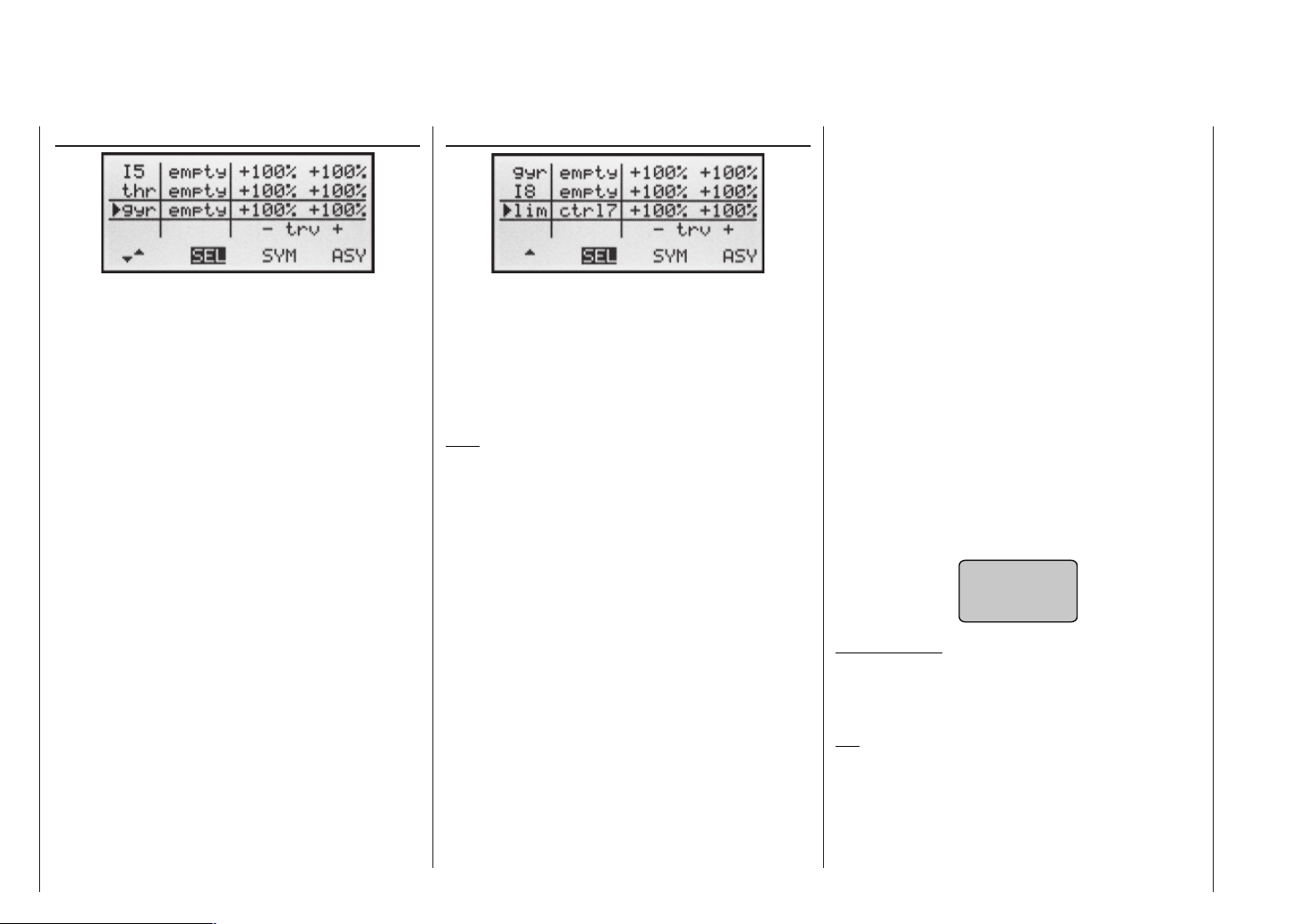
Throttle limit function
„Lim“ input
„Gyro“
If the gyro you are using features infi nitely variable gain
control, then you can pre-set the gyro effect within the
range +/-125%, separately for each fl ight phase, in the
“Gyro” line of the »Heli mixer« menu – see the section
starting on page 66.
Once you have entered these pre-defi ned gain settings
(set separately for each fl ight phase in the »Heli mixer«
menu), you can use a transmitter control such as one of
the two INC / DEC buttons (CTRL 5 or 6) to vary gyro
gain; all you have to do is assign that transmitter control in the “Gyro” line of this menu: in the centre position
of the transmitter control this corresponds to the setting
selected in the »Heli mixer« menu (see page 66). If the
transmitter control is moved from this centre point in the
direction of full travel, gyro gain is increased; towards
the opposite end-point it is reduced. This is a fast, simple method of fi ne-tuning gyro gain when the model is in
fl ight – perhaps to suit varying weather conditions – or
alternatively to fi nd the optimum setting.
In software terms you can also limit the gain range to
both sides by restricting the transmitter control travel.
Meaning and application of “throttle limit”
In contrast to fi xed-wing models, the power output of
the engine or motor of a model helicopter is not controlled directly using the throttle (C1) stick. Instead it is
controlled indirectly by the throttle curve settings which
you set up in the »Heli mixer« menu. It is even possible
to set different throttle curves to suit different stages of
fl ight using fl ight phase programming.
Note:
If your helicopter is fi tted with a speed governor, this
controls the power output.
However, this certainly means that a helicopter’s motor
never gets anywhere near its idle speed during “normal”
fl ying, so it is impossible to start or stop the motor easily unless some other means is used. This applies whether a speed governor or a conventional throttle control
system is in use.
That is the reason why the “Lim” (limit) input is reserved in the Helicopter program for the “Throttle limit” function. A separate transmitter control – as standard this is
the rotary proportional control CTRL 7 at top left of the
transmitter – is employed to limit the setting of the throttle servo to any speed you like, which means that you
can throttle right back to the idle position for starting the
motor. The throttle servo can only follow the throttle curve, and therefore reach its full-throttle setting, if you release full servo travel using the throttle limit control.
For this reason the right-hand positive value in the “Travel” column must be large enough to ensure that it does
not limit the full-throttle setting available via the C1 stick
when the control is at its maximum position. Usually this
means a value in the range 100% to 125%. The lefthand negative value of the input should be set in such a
way that the throttle is closed completely when the digital C1 trim is used, so that you can reliably stop the motor. For the same reason you should leave the bottom
value of the throttle limit slider at +100%.
This variable “limiting” of throttle travel provides a convenient means of starting and stopping the motor. However, it also forms an effective method of recording fl ight
times via the control switch G3, if the latter is set close to the full-throttle point. The throttle limiter function
also provides an additional level of safety if, for example, you have to carry your helicopter to the fl ight line with
the motor running: you simply move the control to its minimum position, and this prevents any accidental movement of the C1 stick affecting the throttle servo.
If the carburettor is too far open when you switch the
transmitter on, you will hear an audible warning, and the
screen displays the message:
throttle
too
high !
Important note:
Setting the “Lim” function input to “free” does not
switch off the Throttle limit function; it just switches
the limiter to “half-throttle”.
Tip:
You can call up the »Servo display« menu to check the
infl uence of the throttle limit slider. Move to this menu by
pressing the SELECT button from the basic transmitter display. Bear in mind that servo output 6 controls the
throttle servo on the mx-16s.
Control settings – Model helicopter
54
Page 55
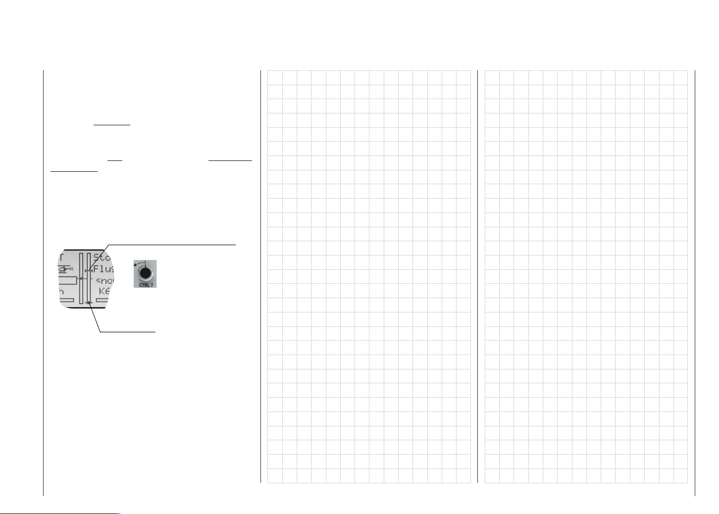
Throttle limit in conjunction with the digital trim
When used with the throttle limit control, the C1 trim
places a marker at the set idle position of the motor; at
this point the motor can be stopped using the trim. If the
trim is in its end-range (see picture below), then a single click immediately takes you back to the marker, i.e. to
the pre-set idle position (see also page 26).
The cut-off trim only acts as idle trim on the throttle limit
in the bottom half of the travel of the throttle limit control, i.e. the marker is only set and stored within this range. For this reason the C1 trim display is also completely
suppressed as soon as the throttle limit control is moved
to the right of the centre position.
Marker line indicates last C1 trim position
(Idle setting)
Centre
Rotary throttle limit
control (CTRL 7)
Trim position at
which motor stops
Marker line displayed
only if rotary throttle
limit control is below
centre. The C1 trim bar
is suppressed above
“Centre”
Control settings – Model helicopter
55
Page 56
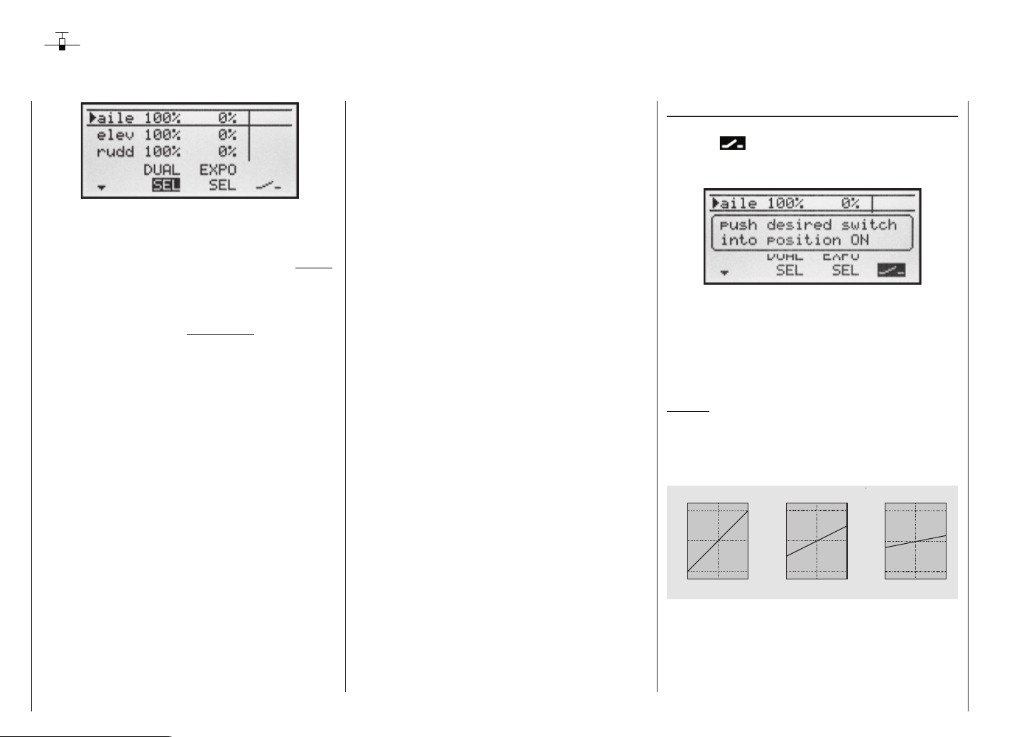
Dual Rate / Expo
Switchable control characteristics for aileron, elevator and rudder
The Dual Rate / Expo function provides a means of switching to reduced control travels, and of infl uencing the
travel characteristics, for aileron, elevator and rudder
(control functions 2 ... 4). This can be carried out in fl ight
by means of external switches.
Dual Rate works in a similar way to transmitter control
travel adjustment in the »Control settings« menu, i.e.
it affects the corresponding stick function, regardless of
whether that function controls a single servo or multiple servos via any number of complex mixer and coupling functions.
For each switch position the servo travels can be set to
any value within the range 0 to 125% of full travel.
Expo works in a different way. If you set a value greater
than 0%, exponential provides fi ne control of the model
around the centre position of the primary control functions (aileron, elevator and rudder), without forfeiting full
travel at the end-points of stick movement. If you set a
value lower than 0%, travel is increased around the neutral position, and reduces towards the extremes of travel. The degree of “progression” can therefore be set to
any value within the range -100% to +100%, where 0%
equates to normal, linear control characteristics.
Another application for exponential is to improve the linearity of rotary-output servos, which are the standard
nowadays. With a rotary servo the movement of the control surface is inevitably non-linear, as the linear movement of the output disc or lever reduces progressively as
the angular movement increases, i.e. the rate of travel of
the control surface reduces steadily towards the extre-
Dual Rate / Expo – Fixed-wing model
56
mes, dependent upon the position of the linkage point
on the output disc or lever. You can compensate for this
effect by setting an Expo value greater than 0%, with the
result that the angular travel of the output device increases disproportionately as stick travel increases.
Like Dual Rates, the Expo setting applies directly to the
corresponding stick function, regardless of whether that
function controls a single servo or multiple servos via
any number of complex mixer and coupling functions.
The Dual Rate and Expo functions can also be switched
on and off together if you assign a switch to the function. The result of this is that Dual Rates and Expo can
be controlled simultaneously using a single switch, and
this can be advantageous – especially with high-speed
models.
Basic set-up procedure
1. Hold the SELECT button pressed in, then use the
right-hand rocker button to select the desired line:
“AIL”, “ELE” or “RUD”.
2. Use the right-hand rocker button to select SEL under
the DUAL or EXPO column, so that you can make
adjustments at that point.
3. Press the SELECT button. The appropriate input fi eld
is now highlighted.
4. Set the desired value using the right-hand rocker button.
5. Press SELECT to conclude the input process and re-
turn to the function fi eld.
Dual Rate function
If you wish to switch between two possible D/R settings,
select the
symbol and assign a physical switch as
described in the section “Assigning switches and control
switches” on page 25.
Select the left-hand SEL fi eld to change the Dual Rate
value, and use the right-hand rocker button in the highlighted fi eld to set the values for each of the two switch
positions separately.
Pressing CLEAR in the highlighted fi eld resets an altered value to 100%.
Caution:
The Dual Rate value should always be at least 20% of
total control travel, otherwise you could lose all control of
that function.
Examples of different Dual Rate values:
D u a l R a t e = 1 0 0 %
1 2 5
®
1 0 0
%
S e r v o T r a v e l
0
- 1 0 0
- 1 2 5
- 1 0 0 % 0
S t i c k D e f l e c t i o n
+ 1 0 0 %
®
D u a l R a t e = 5 0 % D u a l R a t e = 2 0 %
1 2 5
®
1 0 0
%
S e r v o T r a v e l
0
- 1 0 0
- 1 2 5
0
- 1 0 0 %
S t i c k D e f l e c t i o n
+ 1 0 0 %
1 2 5
®
1 0 0
%
0
S e r v o T r a v e l
- 1 0 0
- 1 2 5
- 1 0 0 % 0
®
S t i c k D e f l e c t i o n
+ 1 0 0 %
®
Page 57

Exponential function
If you wish to switch between two settings, select the
fi eld and assign a physical switch as described on
page 25. The assigned switch appears in the screen display together with a switch symbol which indicates the
direction of operation when you move the switch.
Combined Dual Rate and Expo
If you have entered values for Dual Rates and Expo, the
two functions are superimposed as follows:
E x p o = + 1 0 0 % , D / R = 1 2 5 %
1 2 5
®
1 0 0
%
0
S e r v o T r a v e l
E x p o = + 1 0 0 % , D / R = 5 0 % E x p o = - 1 0 0 % , D / R = 5 0 %
1 2 5
®
1 0 0
%
0
S e r v o T r a v e l
1 2 5
®
1 0 0
%
0
S e r v o T r a v e l
For example, the system enables you to fl y with a linear curve characteristic in the one switch position, and to
pre-set a value other than 0% in the other switch position.
To change the Expo value, fi rst select the SEL fi eld,
then use the right-hand rocker button in the highlighted
fi eld to set separate values for each of the two switch
positions:
Pressing CLEAR in the highlighted fi eld resets an altered value to 0%.
Examples of different Expo values:
E x p o = + 1 0 0 % E x p o = + 5 0 % E x p o = - 1 0 0 %
1 2 5
®
1 0 0
%
0
S e r v o T r a v e l
- 1 0 0
- 1 2 5
- 1 0 0 %
0
S t i c k D e f l e c t i o n
+ 1 0 0 %
®
®
S e r v o T r a v e l
- 1 0 0
- 1 2 5
1 2 5
1 0 0
%
- 1 0 0 %
0
0
0
S t i c k D e f l e c t i o n
+ 1 0 0 %
1 2 5
®
1 0 0
%
0
0
S e r v o T r a v e l
- 1 0 0
- 1 2 5
0
- 1 0 0 %
®
S t i c k D e f l e c t i o n
+ 1 0 0 %
®
In these examples the Dual Rate value is 100% in each
case.
- 1 0 0
- 1 2 5
- 1 0 0 %
0
S t i c k D e f l e c t i o n
+ 1 0 0 %
- 1 0 0
- 1 2 5
- 1 0 0 % 0
®
S t i c k D e f l e c t i o n
e.g. “switch back”:
and after moving switch “2” “front”:
+ 1 0 0 %
- 1 0 0
- 1 2 5
- 1 0 0 % 0
®
S t i c k D e f l e c t i o n
+ 1 0 0 %
®
Dual Rate / Expo – Fixed-wing model
57
Page 58

Dual Rate / Expo
Switchable control characteristics for roll, pitch-axis and tail rotor
The Dual Rate / Expo function provides a means of switching to reduced control travels, and infl uencing the travel characteristics, for the roll, pitch-axis and tail rotor
servos (control functions 2 ... 4). This can be carried out
in fl ight by means of an external switch. A separate curve for control function 1 (motor / collective pitch) can be
set separately for throttle, collective pitch and tail rotor in
the »Heli mixer« menu. These curves feature up to fi ve
separately programmable points; see the section starting on page 66 and also page 106.
Dual Rate works in a similar way to transmitter control
travel adjustment in the »Control settings« menu, i.e.
it affects the corresponding stick function, regardless of
whether that function controls a single servo or multiple servos via any number of complex mixer and coupling functions.
For each switch position the servo travels can be set to
any value within the range 0 to 125% of full travel.
Expo works in a different way. If you set a value greater
than 0%, exponential provides fi ne control of the model
around the centre position of the primary control functions (roll, pitch-axis and tail rotor), without forfeiting full
travel at the end-points of stick movement. If you set a
value lower than 0%, travel is increased around the neutral position, and reduces towards the extremes of travel.
The degree of “progression” can be set within the range -100% to +100%, where 0% equates to normal, linear control characteristics.
Another application for exponential is to improve the linearity of rotary-output servos, which are the standard
Dual Rate / Expo – Model helicopter
58
nowadays. With a rotary servo the movement of the control surface is inevitably non-linear, as the linear movement of the output disc or lever reduces progressively as
the angular movement increases, i.e. the rate of travel of
the control surface reduces steadily towards the extremes, dependent upon the position of the linkage point
on the output disc or lever. You can compensate for this
effect by setting an Expo value greater than 0%, with the
result that the angular travel of the output device increases disproportionately as stick travel increases.
Like Dual Rates, the Expo setting applies directly to the
corresponding stick function, regardless of whether that
function controls a single servo or multiple servos via
any number of complex mixer and coupling functions.
The Expo function can also be switched on and off in
fl ight if you assign a switch to it.
The Dual Rate and Expo functions can also be switched
on and off together if you assign a switch to the function. The result of this is that Dual Rates and Expo can
be controlled simultaneously using a single switch, and
this can be advantageous – especially with high-speed
models.
Basic set-up procedure
1. Hold the SELECT button pressed in, then use the
right-hand rocker button to select the desired line:
“Roll”, “Pitch-axis” or “Tail rotor”.
2. Use the right-hand rocker button to select SEL under
the DUAL or EXPO column, so that you can make
adjustments at that point.
3. Press the SELECT button. The appropriate input fi eld
is now highlighted.
4. Set the desired value using the right-hand rocker button.
5. Press SELECT to conclude the input process and re-
turn to the function fi eld.
Dual Rate function
If you wish to switch between two possible D/R settings,
select the
symbol and assign a physical switch as
described in the section “Assigning switches and control
switches” on page 25.
Select the left-hand SEL fi eld to change the Dual Rate
value, and use the right-hand rocker button in the highlighted fi eld to set the values for each of the two switch
positions separately.
Pressing CLEAR in the highlighted fi eld resets an altered value to 100%.
Caution:
The Dual Rate value should always be at least 20% of
total control travel, otherwise you could lose all control of
that function.
Examples of different Dual Rate values:
D u a l R a t e = 1 0 0 %
1 2 5
®
1 0 0
%
S e r v o T r a v e l
0
- 1 0 0
- 1 2 5
- 1 0 0 % 0
S t i c k D e f l e c t i o n
+ 1 0 0 %
®
D u a l R a t e = 5 0 % D u a l R a t e = 2 0 %
1 2 5
®
1 0 0
%
S e r v o T r a v e l
0
- 1 0 0
- 1 2 5
0
- 1 0 0 %
S t i c k D e f l e c t i o n
+ 1 0 0 %
1 2 5
®
1 0 0
%
0
S e r v o T r a v e l
- 1 0 0
- 1 2 5
- 1 0 0 % 0
®
S t i c k D e f l e c t i o n
+ 1 0 0 %
®
Page 59
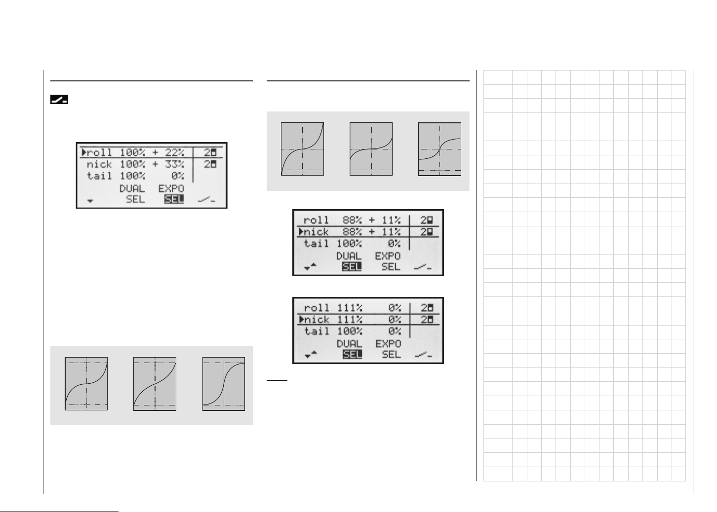
Exponential function
If you wish to switch between two settings, select the
fi eld and assign a physical switch as described on
page 25. The assigned switch appears in the screen display together with a switch symbol which indicates the
direction of operation when you move the switch.
Combined Dual Rate and Expo
If you have entered values for Dual Rates and Expo, the
two functions are superimposed as follows:
E x p o = + 1 0 0 % , D / R = 1 2 5 %
1 2 5
®
1 0 0
%
0
S e r v o T r a v e l
E x p o = + 1 0 0 % , D / R = 5 0 % E x p o = - 1 0 0 % , D / R = 5 0 %
1 2 5
®
1 0 0
%
0
S e r v o T r a v e l
1 2 5
®
1 0 0
%
0
S e r v o T r a v e l
For example, the system enables you to fl y with a linear curve characteristic in the one switch position, and to
pre-set a value other than 0% in the other switch position.
To change the Expo value, fi rst select the right-hand
SEL fi eld, then use the right-hand rocker button in the
highlighted fi eld to set separate values for each of the
two switch positions:
Pressing CLEAR in the highlighted fi eld resets an altered value to 0%.
Examples of different Expo values:
E x p o = + 1 0 0 % E x p o = + 5 0 % E x p o = - 1 0 0 %
1 2 5
®
1 0 0
%
0
S e r v o T r a v e l
- 1 0 0
- 1 2 5
- 1 0 0 %
0
S t i c k D e f l e c t i o n
+ 1 0 0 %
®
®
S e r v o T r a v e l
- 1 0 0
- 1 2 5
1 2 5
1 0 0
%
- 1 0 0 %
0
0
0
S t i c k D e f l e c t i o n
+ 1 0 0 %
1 2 5
®
1 0 0
%
0
0
S e r v o T r a v e l
- 1 0 0
- 1 2 5
0
- 1 0 0 %
®
S t i c k D e f l e c t i o n
+ 1 0 0 %
®
In these examples the Dual Rate value is 100% in each
case.
- 1 0 0
- 1 2 5
- 1 0 0 %
0
S t i c k D e f l e c t i o n
+ 1 0 0 %
- 1 0 0
- 1 2 5
- 1 0 0 % 0
®
S t i c k D e f l e c t i o n
+ 1 0 0 %
- 1 0 0
- 1 2 5
- 1 0 0 % 0
®
S t i c k D e f l e c t i o n
+ 1 0 0 %
®
e.g. “switch back”:
and after moving switch “2” “front”:
Note:
In software terms it would be possible to assign one
of the two control switches G1 or G2 which are available at the C1 stick, but since these are triggered at
+80% and -80% of the transmitter control travel, this
is not a very practical alternative.
Dual Rate / Expo – Model helicopter
59
Page 60

Phase trim
Flight phase-specifi c trims for fl aps, ailerons and elevator
If you have not assigned a switch to “Phase 2” and / or
“Phase 3” in the “Base settings” menu, i.e. you have not
assigned names and switches to these alternative phases, you automatically remain in fl ight phase 1 «normal».
The number and name of this fl ight phase are permanently assigned, and cannot be altered. For this reason the “normal” phase is not stated as Phase 1 in the
»Base settings« menu; it is simply hidden.
If you select the »Phase trim« menu with this basic arrangement, i.e. without setting up fl ight phases, you will
fi nd just the «normal» line on the screen, whose pre-set
values of 0% are not usually changed.
If you wish to enter values other than “0”, e.g. to have
more lift at launch, or to be able to fl y more slowly when
thermalling, or faster when fl ying speed tasks, but
WITHOUT having to change the base settings each
time, then you need to use alternative fl ight phases. This
is done by activating “Phase 2” and, if necessary, “Phase 3” in the »Base settings« menu.
To do this you move to the »Base settings« menu and
assign a relevant name and switch to “Phase 2” and (if
required) “Phase 3”. If you decide to use the three-po-
sition switch SW 6/7, then it is advisable to assign it to
“Phase 2” and “Phase 3” at the extremes, with «normal»
at the centre position.
(At the centre position of SW 6/7 the switch symbols on
the screen should look as in the picture below.)
Once the switches are set, you should assign names
to the switch positions, e.g.: switch “up” from centre =
“Launch”; switch “back” from centre = “Speed”, etc..
You can select from the following names:
• takeoff
• thermal
• dist(ance)
• speed
• aerobat(ic)
• landing
• air-tow
• test
Once assigned, these names will appear in the
transmitter’s basic display, and in the »Phase trim«
menu.
Setting up fl ight phase trims
In the »Phase trim« menu you can adjust the trims for
the previously selected fl ight phases.
The fi rst step is to switch to the phase which you wish to
adjust (the * at far left indicates the currently active phase).
Select the desired control function using the right-hand
rocker button, then hold the SELECT button pressed in
and set the required trim values using the right-hand rocker button.
You can activate the different phases by operating the
assigned phase select switch or switches. Note that the
servos do not change from one setting to another abruptly; they move smoothly with a transition time of
around one second.
Values can be set within the range -125% to +125%.
However, typical values are normally in single fi gures or
low double fi gures.
Note:
When setting up “Phase trim”, only “ELE”, “AIL” and
“ELE” will be available on the screen, or – as shown
above – “FLAP”, “AIL” and “ELE”; this depends on the information you have entered in the “Aileron / fl ap” line of
the »Base settings« menu.
Phase trim – Fixed-wing model
60
Page 61

What is a mixer?
The basic function
Wing mixers
In many models it is often desirable to use a mixer to
couple various control systems, e.g. to link the ailerons
and rudder, or to inter-connect a pair of servos where
two control surfaces are actuated by separate servos. In
all these cases the signal which fl ows directly from the
“output” of a transmitter stick to the associated servo is
“bled off” at a particular point, and the derived signal is
then processed in such a way that it affects the “input” of
another control channel, and therefore eventually another receiver output.
Example:
Controlling two elevator servos using the elevator stick.
Control function
output
3 3
Control channel
Transmitter
control
Note: 0% ... +125% = same course and -125% ... 0% = against course
(receiver output)
Mixer
menus
Mixer
8
4,8 V
Servo
C 577
Best.-Nr. 4101
Servo 1
4,8 V
C 577
Servo
Best.-Nr. 4101
Servo 2
The mx-16s transmitter software contains a large number of pre-programmed coupling functions as standard,
which are designed to mix together two (or more) control
channels. The mixer required in this example is supplied
“ready-made”, and just has to be activated in the software in the “tail” line of the »Base settings« menu in the
form of “2 EL Sv”.
The software also includes three freely programmable linear mixers in the fi xed-wing and helicopter programs,
all of which can be used in each model memory.
For more information please refer to the general notes
on “Free mixers” in the section of this manual starting on
page 76.
(The display varies according to the information you
have entered in the “Motor at C1” and “Ail / Flap” lines in
the »Base settings« menu.)
The mx-16s transmitter’s program contains a series of
pre-programmed coupling functions, and all you have
to do is set the mixer ratios and (optionally) assign a
switch. The number of pre-programmed mixer functions
in the mixer list will vary according to the pre-set “model type” (tail type, number of wing servos, with or without motor – see the section starting on page 38). For
example, if your model is not fi tted with camber-changing fl aps, and you have not entered any fl ap servos
in the »Base settings« menu, all the fl ap mixers in the
program are automatically suppressed, as are the “Brake NN” mixers if you enter “Idle front” or “Idle rear”
in the “Motor at C1” line. This makes the menus clearer
and easier to understand, and also avoids potential programming errors.
Notes:
The position of the camber-changing fl aps in the individual fl ight phases is primarily determined in the »Pha-
se trim« menu; see left page. However, if you wish to be
able to adjust these settings in fl ight, or in general terms
control the fl aps manually, any transmitter control assigned to input “E6” (in the »Control settings« menu – see
page 52) can be used.
This transmitter control then operates the two fl ap servos connected to receiver outputs 6 and 7, provided that
fl ap servos have already been set up in the “Ail / Fl” line
of the »Base settings« menu.
Note:
If a transmitter control is assigned to input “E7”, it will be
de-coupled by the software if two camber-changing fl aps
are defi ned; this is intentional, as it eliminates the danger of errors when a fl ap command is given.
Basic programming procedure
1. Hold the SELECT button pressed in, then use the
right-hand rocker button to select the desired mixer.
Dependent from the mixer, only SEL or additional
is shown in the lower display line.
2. Use the right-hand rocker button to select one of these two fi elds.
3. Press the SELECT button. The appropriate input fi eld
is now highlighted.
4. Set the desired value using the right-hand rocker button, and assign a switch if required.
Negative and positive parameter values are possible;
this may be necessary to obtain the correct direction
of servo rotation (control surface defl ection).
CLEAR sets a changed value in the inverse fi eld
back to thedefault value.
5. Press SELECT to conclude the input process.
Wing mixers – Fixed-wing model
61
Page 62
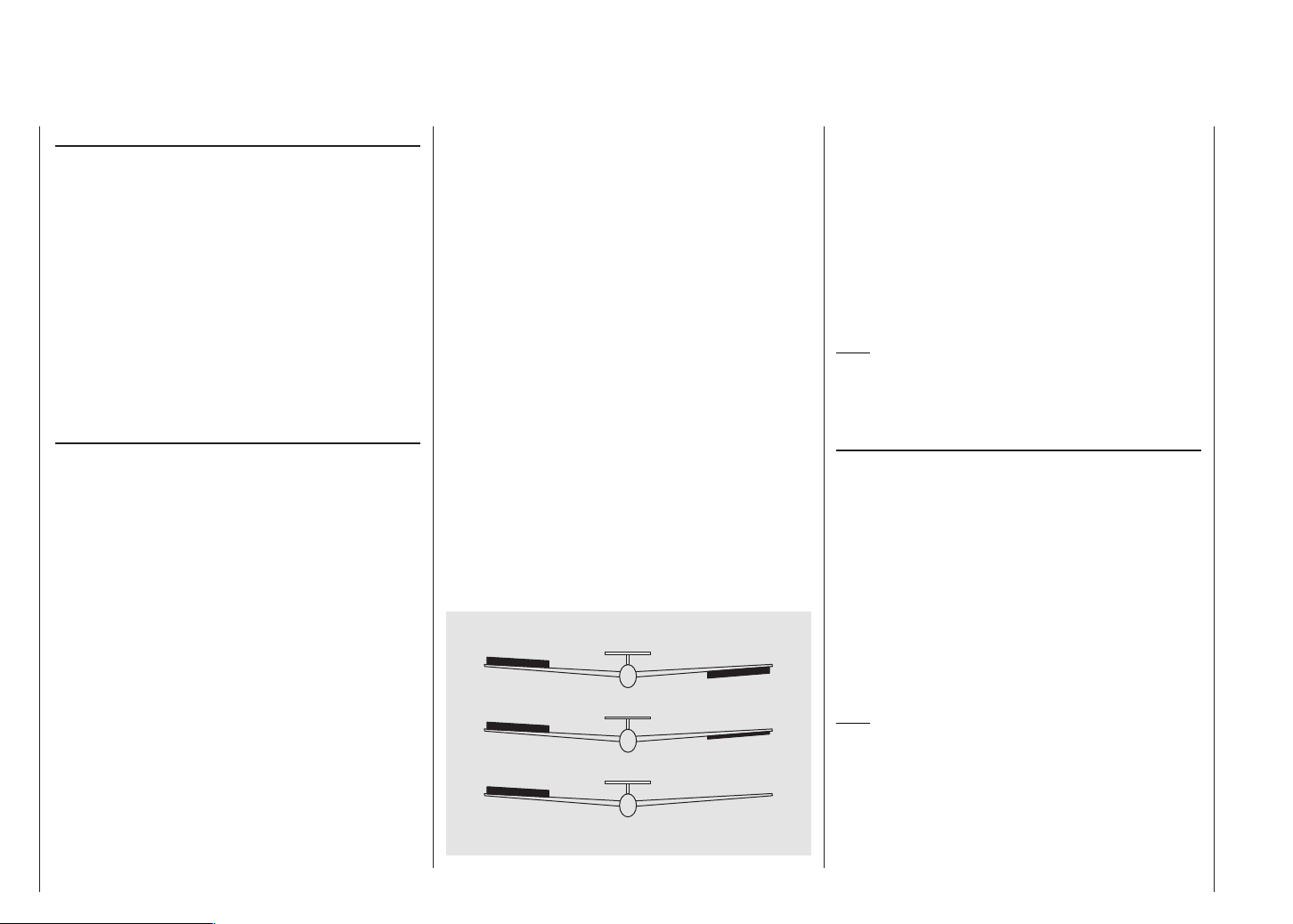
Mixer neutral point (offset)
The neutral point of the mixers
Aileron NN
Elevator NN
Flap NN
is by default the zero point of the transmitter control, i.e.
that is the point at which they have no effect. At the endpoint of the transmitter control the full mixer value is applied.
The default neutral point (“offset”) of the mixers
Airbrake NN
is the front position of the C1 stick (throttle / airbrakes),
at which the airbrakes are always retracted.
diff aile. (differential aileron travel)
Aileron differential compensates for an unwanted sideeffect which occurs when ailerons are defl ected: the problem known as “adverse yaw”. When the ailerons are
defl ected, the drag generated by the down-going aileron
is greater than that produced by the up-going aileron.
The differential drag causes a yawing motion around the
vertical axis in the opposite direction to the desired turn.
This effect is much more pronounced in model gliders
with high aspect ratio wings than in power models with
their much shorter moment arms, and usually has to be
countered by giving a simultaneous rudder defl ection in
the opposite direction to the yaw. However, this in turns
causes additional drag and lowers the aircraft’s effi ciency even further.
Electronic aileron differential is one answer, but it can
only be used if a separate servo is employed for each
aileron. Aileron differential reduces the angular travel
of the down-going aileron relative to the up-going aileron, and this reduces the drag and therefore the adverse yaw. However, this method can only be applied if
each aileron is actuated by its own servo, usually moun-
Wing mixers – Fixed-wing model
62
ted in the wings themselves. The shorter pushrods also
result in virtually slop-free aileron linkages with reliable centring.
Mechanical solutions are also possible, but they usually
have to be “designed in” when the model is built, and the
degree of differential cannot be altered subsequently. In
any case signifi cant mechanical differential tends to cause additional slop in the control system. Electronic differential offers the following important advantages:
It is easily possible to vary the degree of differential without affecting the travel of the up-going aileron. In one
extreme it is possible to suppress the down-aileron defl ection completely, i.e. only the up-going aileron moves
at all, and this arrangement is sometimes called the
“split” setting. Split ailerons not only tend to suppress
adverse yaw, but can even generate positive yaw, which
means that the model yaws in the direction of the turn
when an aileron command is given. In the case of large
model gliders, smooth turns can then be fl own using ailerons alone, which with most models of this type is usually by no means the case.
The adjustment range of -100% to +100% makes it possible to set the correct direction of differential regardless of the direction of rotation of the aileron servos.
0% (normal)
50% (differential)
100% (split)
“0%” corresponds to a normal linkage, i.e. no differential,
while “-100%” or “+100%” represents the “split” function.
For aerobatic fl ying it is necessary to set low absolute
differential values, to ensure that the model rotates exactly along its longitudinal axis when an aileron command is given. Moderate values around -50% or +50%
are typical for making thermal turns easier to fl y. The
split setting (-100%, +100%) is popular with slope fl yers, when ailerons alone are often used for turning the
model.
Note:
Although it is possible to enter negative values in order
to reverse the direction of servo rotation, this is not usually necessary if the correct channels are used.
diff. fl aps (Camber-changing fl ap differential)
The aileron / fl ap mixer (see below) is designed to superimpose an aileron function on the fl aps. Flap differential works like aileron differential, and produces a reduced fl ap movement in the down-direction when they are
used as supplementary ailerons.
The adjustment range of -100% to +100% makes it possible to set the correct direction of differential regardless of the direction of rotation of the servo. “0%” corresponds to a normal linkage, i.e. the servo travel is the
same up and down. A setting of “-100%” or “+100%”
means that the down-travel of the fl aps is reduced to
zero when an aileron command is given (“split” setting).
Note:
Negative values are not usually necessary if the correct
channels are used.
Page 63

ail rudd (Aileron rudder)
In this case the rudder automatically “follows” when an
aileron command is given, and the mixer ratio (degree
of following) can be set by the user. Coupled aileron /
rudder (sometimes abbreviated to CAR; also known as
“combi-switch”) is especially useful for suppressing adverse yaw in conjunction with aileron differential, and
this combination usually makes smooth turns very easy
to fl y. Naturally, the rudder can still be controlled separately by means of its dedicated stick. If an (optional)
switch (SW 1 … 4) is assigned to this function, the mixer
can be switched on and off in fl ight, so that you can control the ailerons and rudder separately if and when you
so desire.
ail fl aps (Aileron fl ap)
rally less than 100%. The adjustment range of -150%
to +150% allows the user to set up the fl ap direction to
match that of the ailerons.
Note:
If your model is equipped with only one fl ap servo, you
should still select “... 2FL” in the “aile/fl ap” line of the
»Base settings« menu (see page 39) but leave the “Ail
Flap” mixer at 0%. In contrast, all the other wing mixers can be used in the usual way.
brak elev (Brake elevator)
Extending any form of airbrakes usually generates an
unwanted change in pitch trim (nose up or nose down);
this is especially marked when a butterfl y (crow) braking
system is deployed (see next page).
This mixer feeds a corrective signal to the elevator to
compensate for this unwanted moment. The adjustment
range is -150% to +150%, but “usual” values are generally in the low double fi gures.
brak fl ap (Brake fl ap)
When you operate the brake function (C1 stick) both fl ap
servos move together for the landing approach; the mixer ratio can be set to any value in the range -150% to
+150%. Down-fl ap is usually selected.
brak aile (Brake aileron)
When you operate the brake function, both aileron servos move together for the landing approach; the mixer ratio can be set to any value in the range -150% to
+150%. It can also be useful to defl ect both ailerons up
slightly when the airbrakes are extended.
This mixer feeds a variable amount of the aileron signal into the fl ap channel. When an aileron command
is given, the fl aps “follow” the ailerons, although usually through a smaller angle, i.e. the mixer ratio is gene-
Wing mixers – Fixed-wing model
63
Page 64
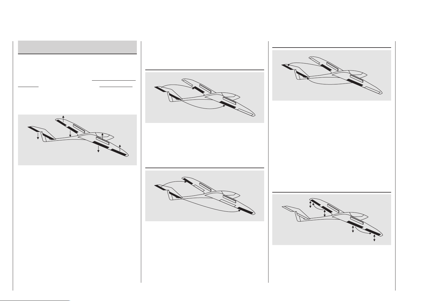
Combination of the “Brake NN” mixers:
“Crow” or “Butterfl y” setting
If you have set up all three airbrake mixers for your model, it is then possible to program a special confi guration
known as the “crow” or “butterfl y” arrangement for glide
path control. In the butterfl y setting both ailerons are defl ected up by a moderate amount, and both fl aps down
by the maximum possible amount. The third mixer provides elevator trim to counteract any unwanted pitch trim
change and maintain the model’s airspeed at a safe level.
This inter-action between the fl aps, ailerons and elevator is used to control the glide angle on the landing approach. Optionally the butterfl y setting can also be used
without the airbrakes or spoilers; nowadays this is very
commonly used for sports and competition aircraft.
If your model features full-span (strip) ailerons which
also double as camber-changing fl aps, the two mixers
“Brake ailerons” and “Brake elevator” can be combined for glide path control. In this case up-fl ap is applied, but the fl aps can still be controlled as ailerons.
Elevator pitch trim compensation is generally required.
If you have programmed aileron differential, the response of the ailerons will inevitably be adversely affected by the extreme “up” defl ection of the ailerons in the
butterfl y setting, because the differential travel reduces
or entirely suppresses the down-aileron defl ection. However, the “up” travel of the ailerons is also greatly rest-
ricted because they are already at or close to their “up”
end-point. The remedy here is to apply “differential reduction”, which is explained in its own section later.
elev fl ap (Elevator fl ap)
The fl aps can be used to enhance the effect of the elevator in tight turns and aerobatics, and this mixer feeds
part of the elevator signal to the fl ap servos. The mixer
direction must be set so that the fl aps move down when
up-elevator is applied, and vice versa.
elev aile (Elevator aileron)
This mixer allows the ailerons to reinforce the elevator
response in the same way as the previous mixer.
fl ap elev (Flap elevator)
When the camber-changing fl aps are lowered, either
using »Phase trim« or by means of a transmitter control
assigned to input “E6”, a pitch trim change (up or down)
may occur. Alternatively it may be desirable for slight
down-elevator to be applied automatically when the
fl aps are raised slightly, in order to increase the model’s
basic airspeed. This mixer can be used to achieve both
purposes.
When the fl aps are deployed, this mixer causes the elevator setting to be corrected automatically according to
the fl ap defl ection. The end-effect is therefore dependent
only upon the magnitude of the corrective value you set.
fl ap aile (Flap aileron)
This mixer causes a variable proportion of the fl ap signal to be mixed in with the aileron channels 2 and 5 so
that the ailerons follow the movement of the fl aps, albeit
normally with a smaller defl ection. The net result is more
even lift distribution over the full wingspan.
Wing mixers – Fixed-wing model
64
Page 65

diff-red (Differential reduction)
The problem of reduced aileron response in the butterfl y
confi guration has been mentioned earlier: if aileron differential is employed, the aileron response on the landing
approach may be adversely affected through the extreme “up” defl ection of the ailerons, permitting virtually no
further up-movement; on the other hand the “down” travel has already been reduced by the programmed differential setting. The overall result is signifi cantly reduced
aileron response compared to the normal setting of the
control surfaces.
In this case you really should use “differential reduction”
it at all possible. This reduces the degree of aileron differential when you invoke the butterfl y setting using the
airbrake stick. Differential is reduced progressively, or
even eliminated altogether, as the airbrake stick is moved towards its end-point.
A value of 0% means that the full programmed aileron
differential is retained. A value of 100% means that the
aileron differential is completely eliminated at the maximum butterfl y setting, i.e. when the airbrakes and other
glide path control surfaces are fully extended. If you set
a value above 100%, the aileron differential is eliminated
even before full travel of the airbrake stick is reached.
Wing mixers – Fixed-wing model
65
Page 66
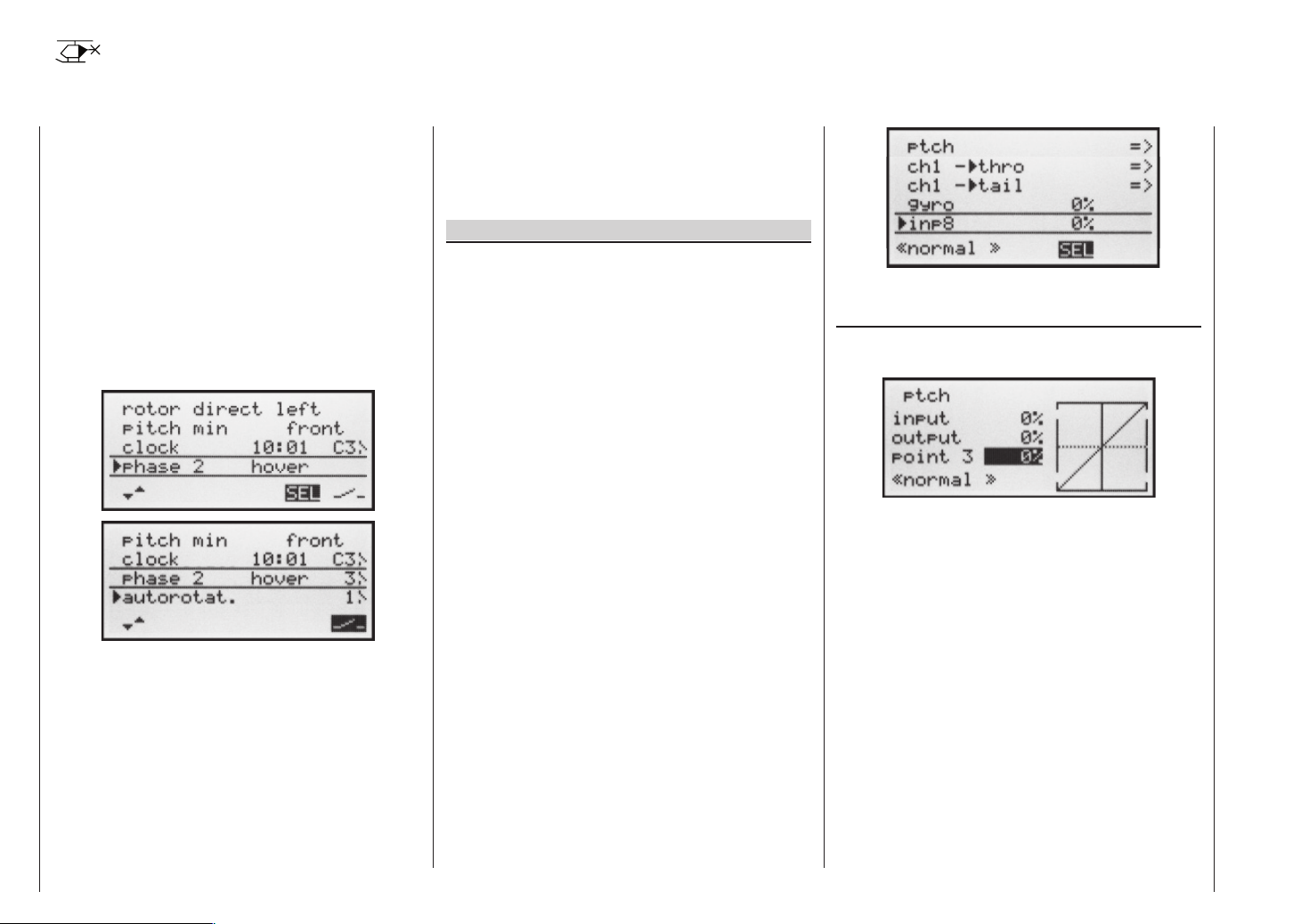
Heli mixer
Flight phase-specifi c mixers for collective pitch, throttle and tail rotor
In the »Base settings« menu a method of switching
fl ight phases can be activated by assigning the appropriate switches to “Phase 2” and “Autorotation”. You can
then switch between the phases “normal” and a second
phase – which you can name yourself – using one of the
switches SW 1 … 4. The third phase – Autorotation –
has precedence over the other two phases. Please note
that switching to autorotation always has priority
over the other two phases.
If you have not yet assigned switches for the fl ight phases, you should do so now. Use the right-hand rocker
button to move to the switch symbol at bottom right, then
press the SELECT button.
Phase 1 always bears the designation «normal». Both
the number and name of this phase are permanently assigned, and cannot be altered. For this reason the “normal” phase is not stated as Phase 1 in the »Base set-
tings« menu; it is simply hidden.
“Phase 2” is assigned the default name «Hover», but
you can change this if you prefer. Hold the SELECT button pressed in, and use the right-hand rocker button to
select one of the following names:
• hover
• aerobat
• aero 3D
• Speed
• Test
Description of the heli mixer
Five-point curves are available for setting up the control characteristics of “collective pitch”, “Ch1 throttle”
and “Ch1 tail rotor”. Using these curves it is possib-
le to program non-linear mixer ratios along the travel of
the transmitter stick for these mixers. Move to the display
page for setting 5-point curves by pressing the SELECT
or ENTER button (see below).
In contrast, the mixers “Ch1 throttle” and “Ch1 tail
rotor” are not required for the “Autorotation” fl ight phase
(described in the section starting on page 74); instead
they are automatically switched to a (variable) pre-defi ned value.
A value must be entered in the “Gyro” and “Input 8” lines: press the SELECT button, then change the value in
the highlighted fi eld using the right-hand rocker button.
Pressing the CLEAR button resets this parameter value
to 0%. All these set-up options are required for the basic
process of setting up a model helicopter.
The name of the currently selected fl ight phase is displayed in the »Heli mixer« menu as well as in the
transmitter’s basic display; this is designed to ensure
that any changes you make actually apply to the correct
fl ight phase. Note that the servos do not change from
one setting to another abruptly; they move smoothly with
a transition time of around one second. This does not
apply to autorotation: when you switch TO autorotation,
the change takes place immediately.
If you operate the switch selected for a particular fl ight
phase, the associated fl ight phase is superimposed at
the bottom edge of the screen, e.g. «normal».
Now you can program the settings for this fl ight phase.
Ptch (Pitch curve (Ch1 collective pitch))
Select the “Collective pitch” line and press ENTER or
SELECT:
The control curve can be based on a maximum of
fi ve nodes, known as “reference points”, which can be
placed along the length of the control travel; separate
curves can be programmed for each fl ight phase.
However, in most cases it is suffi cient to use a smaller
number of reference points when defi ning the collective pitch curve. As a basic rule we recommend that you
start with the three default reference points offered by
the software. These three points, i.e. the two end-points
“Point 1” (collective pitch minimum), “Point 5” (collective pitch maximum) and “Point 3”, exactly in the centre
of the travel, initially describe a linear characteristic for
the collective pitch curve; this is represented in the picture above.
The programming procedure in detail
Start by switching to the desired fl ight phase, e.g. «normal».
Heli mixer – Model helicopter
66
Page 67
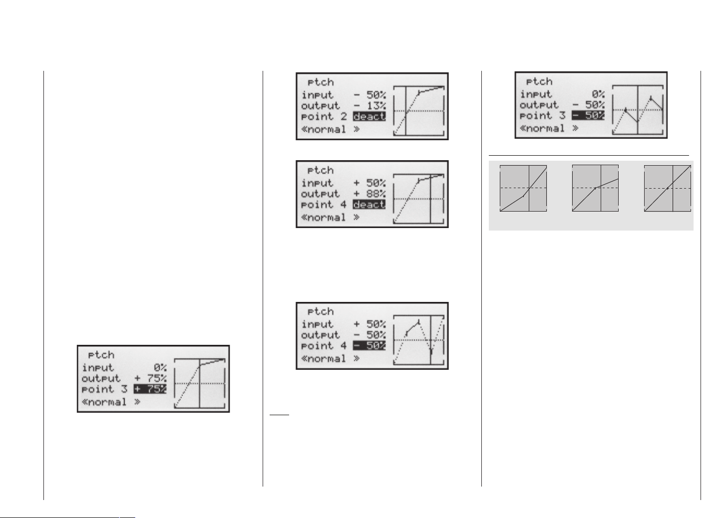
The throttle / collective pitch stick can now be used to
move the vertical line in the graph between the two endpoints “Point 1” and “Point 5”, and parallel to this the momentary position of the stick is displayed in numeric
form in the “Input” line (-100% to +100%).
The point where the vertical line crosses the curve is
termed the “Output”, and this point can be varied within
the range -125% and +125% at a maximum of fi ve reference points. This control signal, modifi ed in this way, affects the collective pitch servos only. In the picture on
the left the stick is exactly at the 0% position at “Point 3”,
and also generates an output signal of 0% due to the linear characteristic of the graph.
By default only points “1” (collective pitch minimum at
-100%), “3” (hover point at 0%) and “5” (collective pitch
maximum at +100% travel) are active.
To set a point you use the associated stick to move the
vertical line to the point you wish to change. The number and current curve value of this point are displayed
in the bottom line in the left-hand half of the screen. The
right-hand rocker button can now be used to change the
current curve value in the highlighted fi eld to any value
within the range -125% to +125%, without affecting the
adjacent points.
… and point “4” to +50% …
This is accomplished using the stick to move the vertical line to the appropriate area. As soon as the message
“inactive” appears in the highlighted value fi eld, you can
activate the associated point by pressing the right-hand
rocker button; it can then be adjusted in the same manner as the other points …
Typical collective pitch curves for different fl ight phases:
+ 1 0 0 %
O u t p u t
- 1 0 0 %
1 2 3 4 5
C o n t r o l T r a v e l
H o v e r
+ 1 0 0 %
O u t p u t
- 1 0 0 %
1 2 3 4 5
C o n t r
o l T r a v e l
A e r o b a t i c s 3 D - F l y i n g
+ 1 0 0 %
- 1 0 0 %
O u t p u t
1 2 3 4 5
C o n t r o l T r a v e l
In this example we have moved reference point “3” to
+75%.
However, points “2” and “4” can optionally be activated,
even though they are disabled by default. In the next example we move point “2” to -50% …
… or reset to “inactive” by pressing the CLEAR button.
Points “1” and “5”, however, cannot be disabled.
Note:
The following illustration, and all the other pictures on
this page, show a control curve we prepared for illustration purposes only. Please note that the curve characteristics by no means represent real collective pitch curves!
Heli mixer – Model helicopter
67
Page 68
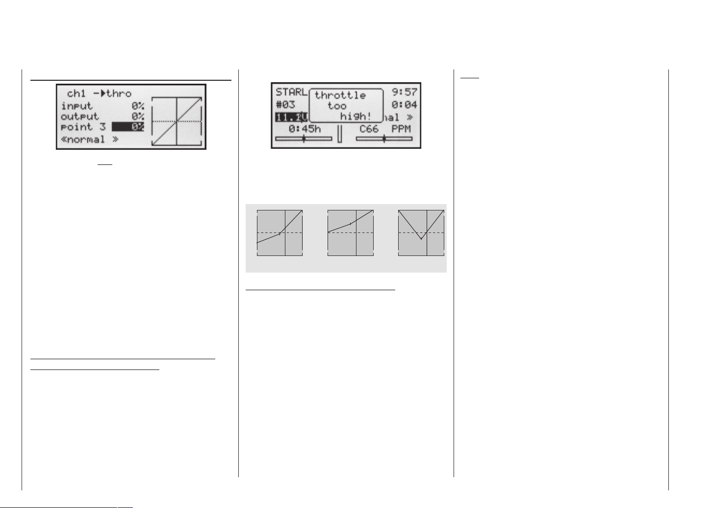
ch1 throttle (throttle curve)
This display refers only to the control curve of the throttle servo.
The throttle curve can also be defi ned using up to
fi ve points, in a similar way to the collective pitch
curve (see previous page).
• In all cases the throttle must be fully open at the endpoint of the throttle / collective pitch stick (exception:
autorotation – see page 74).
• The hover point is normally located at the centre of
the stick travel, and the throttle setting should be adjusted relative to the collective pitch curve in such a
way that the correct system rotational speed is obtained at this point.
• At the minimum position of the throttle / collective
pitch stick the throttle curve should be set up so that
the motor runs at a distinctly higher speed compared
to the idle setting, with the clutch reliably engaged.
In all fl ight phases the motor is started and stopped
using the throttle limiter (see below).
If you are used to a different radio control system which
uses two separate fl ight phases for this – “with idle-up”
and “without idle-up” – please note that the throttle limiter renders this complication superfl uous.
Ensure that the throttle limiter is closed before you start
the motor, i.e. the throttle can only be adjusted within its
idle range using the idle trim. Be sure to read the safety notes on page 72 which refer to this. If the idle is set
too high when you switch the transmitter on, you will see
and hear a clear warning!
The following three diagrams show typical 3-point throttle curves for different fl ight phases, such as hover, aerobatics and 3-D fl ying.
Typical throttle curves for different fl ight phases:
+ 1 0 0 %
O u t p u t
- 1 0 0 %
1 2 3 4 5
C o n t r o l T r a v e l
H o v e r A e r o b a t i c s 3 D - F l y i n g
+ 1 0 0 %
O u t p u t
- 1 0 0 %
1 2 3 4 5
C o n t r
o l T r a v e l
+ 1 0 0 %
O u t p u t
- 1 0 0 %
1 2 3 4 5
C o n t r o l T r a v e l
Notes on using the “Throttle limit” function:
We strongly recommend that you make use of the throttle limit function (»Control settings« menu, page 54).
When you use this function the throttle servo is completely disconnected from the throttle / collective pitch
stick when the rotary proportional control (CTRL 7) is at
its bottom end-point; the motor runs at idle and only responds to the Ch1 trim. This feature enables you to start
the motor from within any fl ight phase. Once the motor
is running, turn the rotary control to the opposite endpoint, so that full control of the throttle servo is returned
to the throttle / collective pitch stick. It is important that
the throttle limiter should not restrict the throttle servo at
its top end-point; you can avoid this by setting the control travel to 125% in the “Lim” line of the »Control set-
tings« menu.
Note:
Releasing the full throttle range, and imposing the throttle limiter again, trips the switching threshold of the control switch “G3” (i.e. in either direction); this switch can
be used for automatically starting and stopping the stopwatch to record the fl ight time, or some similar purpose;
see page 54.
When you select autorotation, the mixer automatically switches the value to a variable pre-set value;
see page 74.
Heli mixer – Model helicopter
68
Page 69
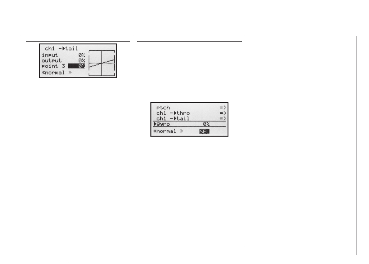
ch1 tail rotor (static torque compensation)
The purpose of this mixer is to provide static compensation for main rotor torque. First ensure in the »Base set-
tings« menu that the direction of main rotor rotation has
been entered correctly.
The tail rotor control curve can also be defi ned
using up to fi ve points, in a similar way to the collective pitch curve (see previous page).
This mixer should be set up in such a way that the helicopter does not rotate around the vertical (yaw) axis (i.e.
does not deviate from the hover heading) during a long
vertical climb or descent, due to the change in torque of
the main rotor. At the hover the yaw trim should be set
using the digital tail rotor trim lever only.
For a reliable torque compensation setting it is essential that the collective pitch and throttle curves have been
set up correctly, i.e. that main rotor speed remains constant over the full range of collective pitch.
By default the software includes a tail rotor curve with a
linear mixer ratio of 30%. You can modify the mixer, and
set asymmetrical mixer ratios above and below the hover point, using the method described above.
When you select autorotation, the mixer automatically switches the value to a variable pre-set value;
see page 74.
Gyro (adjusting gyro gain)
Most modern gyro systems feature proportional, infi nitely variable adjustment of gyro gain.
If the gyro you wish to use also features this option, the
fl ight phase-specifi c static gyro gain adjustment facility enables you to fl y normal, slow fl ights with maximum
gyro stabilisation, but to reduce the gyro effect for highspeed circuits and aerobatics. We recommend that you
set up switchable fl ight phases for this, and set different
gain settings for each phase in the “Gyro” line; values
between -125% and +125% are possible.
Based on the end-points determined for each fl ight phase, gyro gain can be varied proportionally between minimum and maximum by means of a transmitter control assigned in the “Gyro” line in the »Control settings«
menu (see page 52). This could be transmitter control
5 (CTRL 5), which would provide infi nitely variable gyro
gain control:
• At the centre position of this transmitter control the
gyro effect always corresponds to the settings selected here.
• If you press the INC / DEC button in the direction of
full travel (away from centre), the gyro gain increases
accordingly …
• … and reduces again if you press it in the direction of
the opposite end-point.
Adjusting the gyro sensor
If you wish to set up a gyro to achieve maximum possible stabilisation of the helicopter around the vertical axis,
please note the following points:
• The mechanical control system should be as freemoving and accurate (slop-free) as possible.
• There should be no “spring” or “give” in the tail rotor
linkage.
• You must use a powerful and – above all – fast servo
for the tail rotor.
When the gyro sensor detects a deviation in yaw, the
faster it adjusts the thrust of the tail rotor, the further
the gyro gain adjustor can be advanced without the
tail of the model starting to oscillate, and the better the
machine’s stability around the vertical axis. If the corrective system is not fast enough, there is a danger that the
model’s tail will start to oscillate even at low gyro gain
settings, and you then have to reduce gyro gain further
using the INC / DEC button to eliminate the oscillation.
If the model is fl ying forward at high speed, or hovering
in a powerful headwind, the net result of the stabilising
effect of the vertical fi n combined with the gyro’s stabilising effect may be an over-reaction which manifests itself as tail oscillation. In order to obtain optimum stabilisation from a gyro in all fl ight situations, you should
make use of the facility to adjust gyro gain from the
transmitter via the INC / DEC button (CTRL 5).
Heli mixer – Model helicopter
69
Page 70
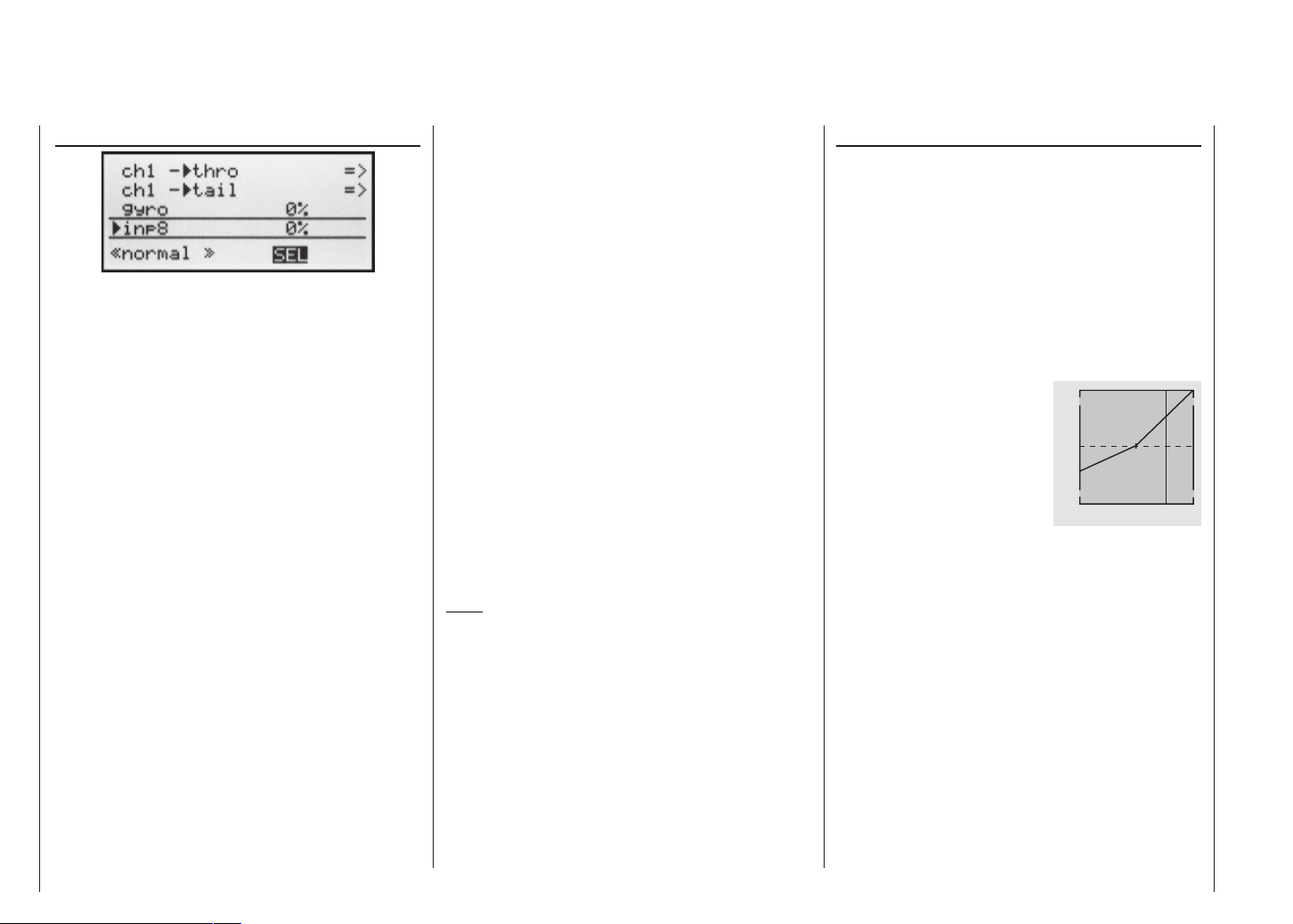
Adjusting the throttle and collective pitch curves
Practical procedure
In 8 (Input 8)
The adjustment facilities in this line of the menu are only
relevant if your model helicopter is fi tted with a speed
governor (regulator) which maintains a constant system
rotational speed. The settings should then be carried out
in accordance with the instructions supplied with the governor you intend to use.
Although the throttle and collective pitch control systems
are based on separate servos, they are always operated
in parallel by the throttle / collective pitch stick (except
when autorotation is invoked). The Helicopter program
automatically couples the functions in the required way.
In the mx-16s program the trim lever of control function
1 only affects the throttle servo, i.e. it acts as idle trim
(see “Digital trims” on page 26).
The process of adjusting throttle and collective pitch correctly, i.e. setting the motor’s power curve to match the
collective pitch setting of the main rotor blades, is the
most important aspect of setting up any model helicopter. The program of the mx-16s provides independent
adjustment facilities for the throttle, collective pitch and
torque compensation curves.
These curves can be defi ned using a maximum of fi ve
reference points. To defi ne the control curves all you
have to do is set individual values for these fi ve points
on the travel of the throttle / collective pitch stick.
However, before you set up the throttle / collective pitch
function it is important to adjust the mechanical linkages
to all the servos accurately, in accordance with the setup notes provided by the helicopter manufacturer.
Note:
The hover point should always be set to the centre
position of the throttle / collective pitch stick.
Idle setting and throttle curve
The idle setting is adjusted solely with the throttle limiter closed, using the trim lever of the C1 function. Reference point “1” of the throttle curve defi nes the throttle setting when the helicopter is in a descent, but without
affecting the hover setting.
This is a case where you can exploit fl ight phase programming to use different throttle curves. An increased
system rotational speed below the hover point proves to
be useful in certain circumstances, for example for fast,
steep landing approaches with greatly reduced collective pitch, and for aerobatics.
+ 1 0 0 %
The diagram shows a curve with
a slightly altered throttle setting
below the hover point at the centre
of stick travel.
O u t p u t
- 1 0 0 %
1 2 3 4 5
C o n t r o l T r a v e l
Different throttle curves are programmed for each fl ight
phase, so that you can use the optimum set-up both for
hovering and aerobatics:
• Low system rotational speed with smooth, gentle
control response and low noise at the hover.
• Higher speed for aerobatics with motor power settings close to maximum. In this case the throttle curve also has to be adjusted in the hover range.
Heli mixer – Model helicopter
70
Page 71

The basic set-up procedure
Although the mx-16s transmitter provides a broad range of adjustment for the collective pitch and throttle curves, it is essential that you fi rst adjust all the mechanical linkages in the model according to the information
supplied by the helicopter manufacturer, i.e. all the system linkages should already be approximately correct in
mechanical terms. If you are not sure of this, an experienced helicopter pilot will be glad to help you with this
basic set-up.
The throttle linkage must be adjusted in such a way that
the throttle is just at the “fully open” position at the fullthrottle setting. When the throttle limiter is at the idle position, the C1 trim lever should just be able to close the
throttle completely, without the servo striking its mechanical end-stop (quick throttle adjustment using the “digital trim”: see page 26).
Take your time, and carry out these adjustments very
carefully by adjusting the mechanical linkage and / or
changing the linkage point on the servo output arm or
the throttle lever. Only when you are confi dent that all
is well should you start optimising and fi ne-tuning the
throttle servo using the transmitter’s electronic facilities.
Caution:
Read all you can about motors and helicopters, so
that you are aware of the inherent dangers and the
cautionary measures required before you attempt to
start the motor for the fi rst time!
With the basic set-up completed, it should be possible to start the motor in accordance with the operating instructions supplied with it, and adjust the idle setting using the trim lever of the throttle / collective pitch
stick. The idle position which you set is indicated in the
transmitter’s basic screen display by a horizontal bar
in the display of the C1 trim lever’s position. Refer to
page 26 of this manual for a full explanation of the digi-
tal trims.
Approximately at the mid-point of the collective pitch
stick the model should lift off the ground and hover at
the rotational speed you wish to use. If this is not the
case, correct the settings as follows:
1. The model does not lift off until the collective
pitch stick is above the centre point.
a) Rotational speed too low
Remedy: increase the value
for the throttle servo parameter
at Point 3 of the stick travel in
the “Ch1 throttle” mixer, as
shown in the graph.
b) Rotational speed too high
Remedy: increase the blade
pitch angle for collective pitch
at Point 3 of the stick travel in
the “Ch1 collective pitch
curve” menu, as shown in the
graph.
+ 1 0 0 %
H o v e r
P o i n t
O u t p u t
- 1 0 0 %
1 2 3 4 5
C o n t r o l T r a v e l
+ 1 0 0 %
H o v e r
P o i n t
O u t p u t
- 1 0 0 %
1 2 3 4 5
C o n t r o l T r a v e l
2. The model lifts off below the centre point.
a) Rotational speed too high
Remedy: reduce the throttle
opening in the “Ch1 thrott-
le” mixer at Point 3 of the stick
travel, as shown in the graph..
+ 1 0 0 %
O u t p u t
- 1 0 0 %
1 2 3 4 5
C o n t r o l T r a v e l
H o v e r
P o i n t
b) Rotational speed too low
+ 1 0 0 %
Remedy: reduce the blade
pitch angle for collective pitch
at Point 3 of the stick travel in
the “Ch1 collective pitch
H o v e r
P o i n t
O u t p u t
curve”, as shown in the graph.
- 1 0 0 %
1 2 3 4 5
C o n t r o l T r a v e l
Important:
You should persevere with this adjustment procedure
until the model hovers at the correct rotational speed at
the centre point of the throttle / collective pitch stick. All
the other model settings depend upon the correct setting
of these parameters!
The standard set-up
The remainder of the standard adjustment procedure is completed on the basis of the fundamental set-up
which you have just carried out, i.e. we now assume that
the model hovers in normal fl ight at the centre point of
the throttle / collective pitch stick, with the correct rotor
speed. This means that your model helicopter is capable of hovering and also fl ying circuits in all phases whilst
maintaining a constant system rotational speed.
The climb setting
The combination of throttle hover setting, collective pitch
setting for the hover and the maximum collective pitch
setting (Point 5) now provides you with a simple method
of achieving constant system rotational speed from the
hover right to maximum climb.
Start by placing the model in an extended vertical climb,
holding the collective pitch stick at its end-point: motor
speed should not alter compared with the hover setting.
If motor speed falls off in the climb, when the throttle is
already fully open and no further power increase is possible (this assumes that the motor is correctly adjusted),
then you should reduce maximum blade pitch angle at
Heli mixer – Model helicopter
71
Page 72
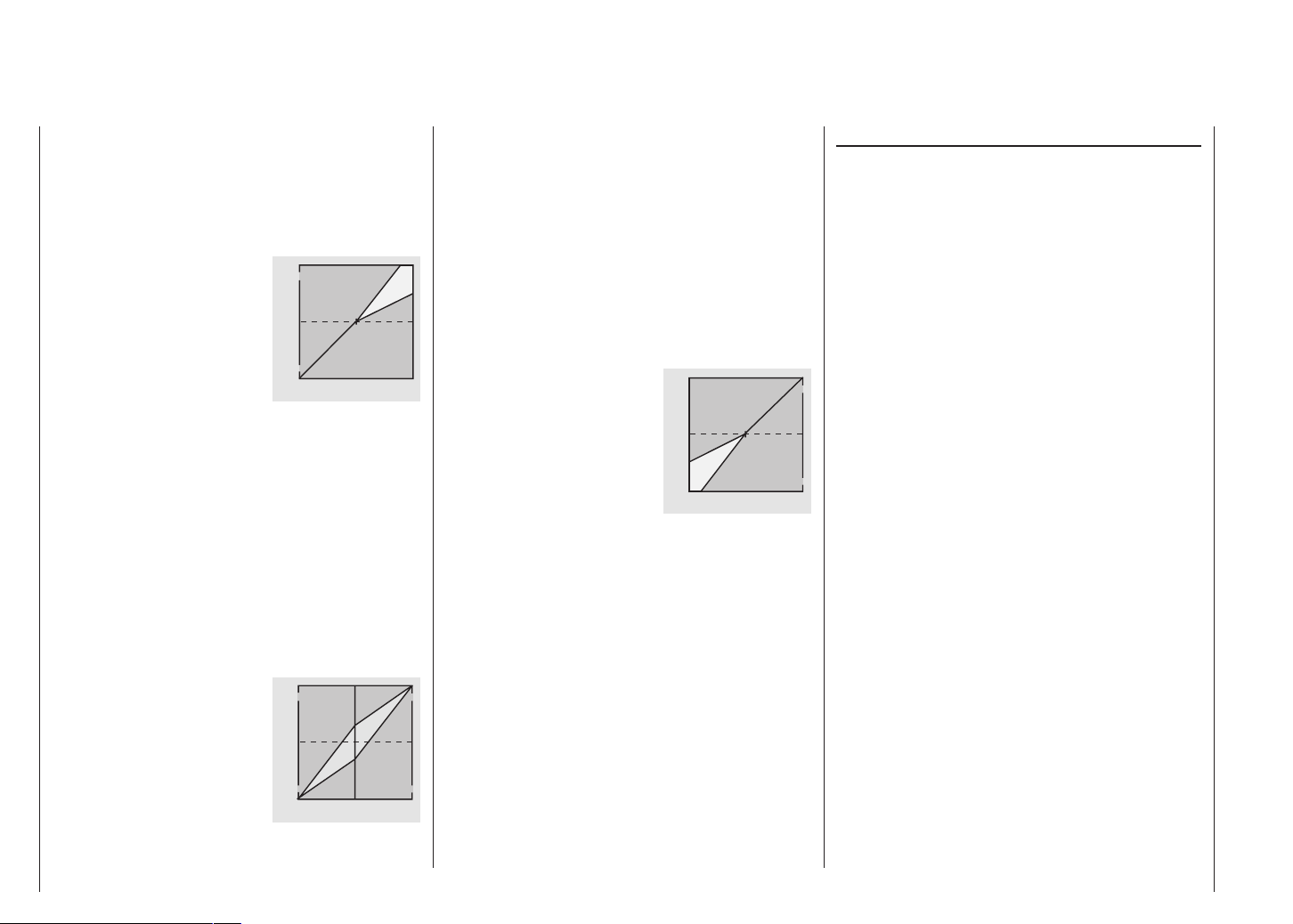
full defl ection of the collective pitch stick, i.e. the value at
Point 5. Conversely, if motor speed rises during the vertical climb, you should increase the pitch angle. This is
done by moving the vertical line to Point 5 using the collective pitch stick, and changing its value accordingly
using the right-hand rocker button.
+ 1 0 0 %
H o v e r
P o i n t
O u t p u t
This diagram only shows the
changes to the collective pitch
maximum value.
- 1 0 0 %
1 2 3 4 5
C o n t r o l T r a v e l
Now bring the model back to the hover, which again
should coincide with the mid-point of the C1 stick. If you
fi nd that the collective pitch stick now has to be moved from the mid-point in the direction of “higher”, then
you should correct this deviation by slightly increasing
the collective pitch angle at the hover – i.e. Point 3 – until the model again hovers at the stick centre point. Conversely, if the model hovers below the mid-point, correct
this by reducing the pitch angle again.
You may fi nd that it is also necessary to correct the
throttle opening at the hover point (Point 3) in the “Ch1
throttle” menu.
+ 1 0 0 %
This diagram only shows the
change in the hover point, i.e.
collective pitch minimum and
maximum have been left at -100%
and +100% respectively.
O u t p u t
- 1 0 0 %
1 2 3 4 5
C o n t r o l T r a v e l
Continue adjusting these settings until you really do
achieve constant main rotor speed over the full control
range between hover and climb.
The descent adjustment should now be carried out from
a safe height by fully reducing collective pitch to place
the model in a descent from forward fl ight; adjust the
collective pitch minimum value (Point 1) so that the model descends at an angle of 60 … 80°. This is done by
selecting the graph for “Collective pitch”, moving the vertical line to Point 1 using the collective pitch stick, and
adjusting the value accordingly using the right-hand rocker button.
+ 1 0 0 %
H o v e r
P o i n t
O u t p u t
As an example, this diagram
shows only the changes in the
collective pitch minimum value.
- 1 0 0 %
1 2 3 4 5
C o n t r o l T r a v e l
Once the model descends reliably as described, adjust
the value for “Throttle minimum” – the value of Point 1
on the graph of the “Ch1 throttle” mixer – so that system rotational speed neither increases nor declines. This
completes the set-up procedure for throttle and collective pitch.
Important fi nal notes
Before you start the motor, check carefully that the
throttle limiter is completely closed, so that the throttle
can be controlled by the trim lever alone. If the throttle is
too far open when you switch on the transmitter, you will
see and hear a warning. If you ignore this and start the
motor with the throttle too far advanced, there is a danger that the motor will immediately run up to speed after starting, and the centrifugal clutch will immediately engage.
For this reason you should:
always grasp the rotor head fi rmly
when starting the motor.
However, if you accidentally start the motor with the
throttle open, the rule is this:
Don’t panic!
Hang on to the rotor head regardless!
Don’t let go!
Immediately close the throttle, even though there may
be a risk of damaging the helicopter’s drive train, because:
it is vital that YOU ensure
that the helicopter cannot possibly
move off by itself in an uncontrolled manner.
The cost of repairing a clutch or even the motor itself is
negligible compared to the damage which a model helicopter can cause if its spinning rotor blades are allowed
to wreak havoc.
Make sure that nobody else is standing
in the primary hazard zone around the helicopter.
You must never switch abruptly from idle to the fl ight setting by suddenly increasing system rotational speed.
This causes the rotor to accelerate quickly, resulting in
premature wear of the clutch and gear train. The main
rotor blades are generally free to swivel, and they may
Heli mixer – Model helicopter
72
Page 73

be unable to keep pace with such swift acceleration, in
which case they might respond by swinging far out of
their normal position, perhaps resulting in a boom strike.
Once the motor is running you should slowly increase
system rotational speed using the throttle limiter.
Heli mixer – Model helicopter
73
Page 74

Heli mixer
Autorotation settings
Autorotation allows full-size and model helicopters to
land safely in a crisis, i.e. if the power plant should fail.
It can also be used if the tail rotor should fail, in which
case cutting the motor and carrying out an autorotation landing is the only possible way of avoiding a highspeed uncontrollable rotation around the vertical axis,
invariably terminating in a catastrophic crash. And that is
the reason why switching INTO autorotation occurs without any delay.
When you switch to the autorotation phase the heli mixer change as shown in this screen shot:
During an autorotation descent the main rotor is not driven by the motor; it is kept spinning only by the airfl ow
through the rotor plane caused by the speed of the descent. The rotational energy stored in the still spinning rotor can be exploited to allow the machine to fl are out, but
this can only be done once. For this reason “autos” are
only likely to be successful if the pilot has plenty of experience in handling model helicopters, and has also set
up the appropriate functions with great care.
Once you have suffi cient experience you should practise autorotation landings at regular intervals, not only so
that you can demonstrate your all-round fl ying skill by
fl ying the manoeuvre in competitions, but also so that
you are in a position to land the helicopter undamaged
from a great height if the motor should fail. For this purpose the program provides a range of adjustment facilities which are designed to help you fl y your helicopter in
its unpowered state. Please note that the rotation setting
Heli mixer / Autorotation – Model helicopter
74
takes the form of a complete third fl ight phase, for which
all the adjustment facilities are available which can be
varied separately for all fl ight phases, especially trims,
collective pitch curve settings etc..
Ptch (Collective pitch curve (Ch1 collective pitch))
In powered fl ight the maximum blade pitch angle is limited by the motor power which is available; however, in autorotation the angle is only limited by the point
at which the airfl ow over the main rotor blades breaks
away. Nevertheless, to provide suffi cient upthrust even
when rotational speed is falling off, it is necessary to
set a greater maximum collective pitch value. Press SE-
LECT or ENTER to select the graph page of “Collective pitch”, and then move the vertical line to Point 5 using
the transmitter stick. Start by setting a value which is
about 10 to 20% higher than the normal collective pitch
maximum; any more than this, and the helicopter may
balloon up again during the fl are following the autorotation descent. If this happens, the rotational speed of
the main rotor will quickly decline to the point where it
collapses, and the helicopter ends up crashing to the
ground from a considerable height.
Under certain circumstances the collective pitch minimum setting may also differ from the normal fl ight setting; this depends on your piloting style for normal fl ying.
In any case you must set a suffi ciently generous collective pitch minimum value at Point 1 to ensure that your
model can be brought from forward fl ight at moderate
speed into a descent of around 60 ... 70° when collective
pitch is reduced to minimum.
Most helicopter pilots already use such a setting for normal fl ying, and if this applies to you, you can simply adopt the same value.
If the angle is too shallow, increase the value.
Approach Angle
in strong
wind
in moderate
wind
no wind
Approach angle
under varying wind
conditions.
75°
60°
45°
For autorotation the collective pitch stick itself may not
be positioned right at the bottom of its travel; typically it
is between the hover position and the bottom end-point,
giving the pilot scope for correction if necessary, i.e. the
chance to adjust the model’s pitch inclination using the
pitch-axis control.
You can shorten the approach by pulling back on the
pitch-axis stick and gently reducing collective pitch, or
alternatively extend the approach by pushing forward on
the pitch-axis stick and gently increasing collective pitch.
Throttle (throttle curve)
In a competition the pilot is expected to cut the motor completely, but for practice purposes this is certainly not advisable. Instead set the throttle so that the motor runs at a reliable idle during autorotation, so that you
can open the throttle immediately to recover from an
emergency.
Tail rotor (static torque compensation)
For normal fl ying the tail rotor is set up in such a way
that it compensates for motor torque when the helicopter
is hovering. This means that it already generates a certain amount of thrust even in its neutral position. The level of thrust is then varied by the tail rotor control system, and also by the various mixers which provide all
manner of torque compensation, while the tail rotor trim
is also used to compensate for varying weather conditi-
Page 75

ons, fl uctuations in system rotational speed and other infl uences.
However, in an autorotation descent the main rotor is not
driven by the motor, and therefore there is no torque effect for which compensation is required, i.e. which the
tail rotor would have to correct. For this reason all the
appropriate mixers are automatically switched off in autorotation mode.
However, the basic tail rotor setting has to be different
for autorotation, as the compensatory thrust described
above is no longer required.
Stop the motor and place the helicopter horizontal. With
the transmitter and receiving system switched on, select
the »Autorotation« fl ight phase. Fold both tail rotor bla-
des down and change the blade pitch angle to zero degrees using the “Tail rotor” menu. Viewed from the rear,
the tail rotor blades should now be parallel to each other.
Depending on the friction and running resistance of the
gearbox, you may fi nd that the fuselage still yaws slightly in an autorotation descent. If necessary, the relatively
slight torque which causes this effect must then be corrected by adjusting the tail rotor blade pitch angle. This
value will always be a small fi gure between zero degrees and a pitch angle opposed to the direction of tail
rotor pitch required for normal fl ight.
Heli mixer / Autorotation – Model helicopter
75
Page 76

General notes regarding freely programmable mixers
The two menus »Wing mixers« and »Heli mixer«, as
described on the preceding pages, contain a wide range
of ready-programmed coupling functions. The basic meaning of mixers has already been explained on page 61,
together with the principle on which they work. In the following section you will fi nd more general information relating to “free mixers”:
In addition to the pre-programmed mixers mentioned
above, the mx-16s offers three freely programmable mixers which can be used in every model memory; their inputs and outputs can be selected to suit your exact requirements.
Any control function (transmitter control 1 to 8) can be
assigned as the input signal of a “free mixer”. Alternatively any switch can be assigned as the input signal
using what is termed the “switch channel” (see below).
The control function itself consists of the transmitter control signal and any control characteristics as defi ned, for
example, in the »Dual Rate / Expo« and »Control set-
tings« menus.
The mixer output acts upon a freely selectable control
channel (1 to max. 8 – depending on receiver type). Before the signal is passed to the associated servo, the
only infl uences which can act upon it are those defi ned
in the »Servo settings« menu, i.e. the servo reverse,
neutral point offset and travel functions.
One control function can be set up to affect several mixer inputs simultaneously, if, for example, several mixers
are to be arranged to work in parallel.
Conversely it is possible for several mixer outputs to affect one and the same control channel.
The following description of the free mixers includes examples of such arrangements.
In software terms the default setting for any freely programmable mixer is that it is constantly switched on, but
it is also possible to assign an optional ON / OFF switch
Free mixers
76
to it. However, since there are so many functions to
which switches can potentially be assigned, you should
take care not to assign a confusing number of functions
to any particular switch.
The two important mixer parameters are as follows:
• … the mixer ratio, which defi nes the extent to which
the input signal acts on the output of the control
channel which is programmed as the mixer output.
• … the neutral point, which is also termed the “off-
set”. The offset is that point on the travel of a transmitter control (stick, rotary proportional knob CTRL 7
or INC / DEC buttons CTRL 5 / 6) at which the mixer
has no infl uence on the control channel which is defi ned as its output. Normally this is the centre point of
the transmitter control, but the offset can be placed at
any point on the control’s travel.
Switch channel “S” as mixer input
In some cases a constant control signal is all that is required as the mixer input; a typical application would be
for slight up-elevator trim when an aero-tow coupling is
closed – independent of the normal elevator trim. If you
then assign a switch, you can switch to and fro between
the two mixer end-points, and adjust the supplementary
elevator trim defl ection by altering the mixer input.
To identify this special arrangement, this mixer input
control function in the program is designated “S” for
“switch channel”. If you do not want the mixer output to
be affected by the standard transmitter control, the control can be de-coupled from the function input of the “receiving” control channel by entering “free” in the »Cont-
rol settings« menu; see pages 50 and 52. The following
menu description includes an example which will make
this function clear.
Page 77

Free mixers
Linear mixers
For each model memory (1 to 12) three linear mixers
are available, with the additional possibility of non-linear
characteristic curves.
In this fi rst section we will concentrate on the programming procedure for the fi rst screen page. We will then
move on to the method of programming mixer ratios, as
found on the second screen page of this menu.
Basic programming procedure
1. Hold the SELECT button pressed in, and select mi-
xer 1 ... 3 using the right-hand rocker button.
2. Press SELECT. The input fi eld “from” is highlighted
(inverse video).
3. Defi ne the mixer input “from” using the right-hand rocker button.
4. Press SELECT, move to SEL under the “to” column
using the right-hand rocker button, and press SE-
LECT once more.
The input fi eld „to“ is shown inverse.
5. Defi ne the mixer input “to” using the right-hand rocker
button.
6. Optionally: press SELECT, move to SEL under the
“type” column using the right-hand rocker button; you
can now include the Ch1 … Ch 4 trim lever for the
mixer input signal (“Tr” for trim).
...and/or switch to the switch symbol; press SELECT
again and select a switch if necessary.
7. Press SELECT, move to
rocker button, and press SELECT or ENTER.
8. Defi ne the mixer ratios on the second screen page.
9. Press ESC to switch back to the fi rst page.
using the right-hand
“from” column
Press the SELECT button, then use the right-hand rocker button to select one of the control functions 1 … 8
or S in the highlighted fi eld of the selected mixer line.
In the interests of clarity, the control functions 1 ... 4 are
abbreviated as follows when dealing with the Wing mixers:
c1 Throttle / airbrake stick
ar Aileron stick
el Elevator stick
rd Rudder stick
… and in the Heli program:
1 Throttle / collective pitch stick
2 Roll stick
3 Nick stick
4 Tail rotor stick
Note:
Don’t forget to assign a transmitter control to the selected control function 5 ... 8 in the »Control settings«
menu.
“S” for switch channel
The letter “S” (switch channel) in the “from” column has
the effect of passing a constant input signal to the mixer input, e.g. in order to apply a little extra up-elevator trim when an aero-tow coupling is closed, as mentioned earlier.
Once you have assigned a control function or the letter
“S”, an additional SEL fi eld appears in the …
“to” column
At this point you can defi ne the control channel as the
mixer destination, i.e. the mixer output. At the same time
additional fi elds appear in the bottom line of the screen:
In this example three mixers have already been defi ned.
The second mixer (“Brake elevator”) is already familiar to us from the »Wing mixers« menu. As a general
rule you should always use these pre-programmed mixers fi rst if possible.
However, if you need asymmetrical mixer ratios on both
sides of centre, or wish to program a non-linear curve,
or have to offset the mixer neutral point, then you should
set or leave the pre-set mixers at “0”, and program one
of the free mixers instead.
Erasing mixers
If you need to erase a mixer that you have already defi ned, simply press the CLEAR button in the highlighted
fi eld of the “from” column.
Mixer switches
In our example above, a physical switch “1” and the control switch “G1” have been assigned to the two linear mixers 1 and 2, and switch 3 to mixer 3.
The switch symbol to the right of the switch number
shows the current status of that switch.
Any mixer to which no switch has been assigned in
the column is permanently switched on.
Free mixers
77
Page 78
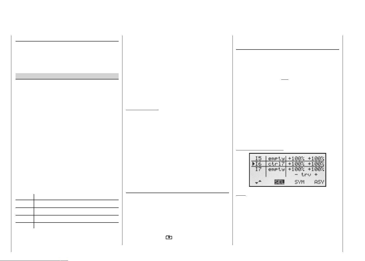
“Type” column (including the trim)
If you wish, and if you are using one of the primary control functions 1 ... 4 (sticks), you can set the trim value
of the digital trim lever to affect the mixer input. Use the
right-hand rocker button to select “tr” in the highlighted
fi eld for the mixer you are programming.
Additional special features of free mixers
If you set up a mixer whose input is the same as its output, e.g. C1 C1, exotic results can be obtained in
conjunction with the option of switching a free mixer on
and off. You will fi nd one typical example of this on pages 92 … 93.
Before we come to setting mixer ratios, and conclude
with a few examples, we have to consider what happens
if a mixer input is allowed to act on the pre-set coupling
of aileron servos, fl ap servos or collective pitch servos:
• Fixed-wing models:
Depending on the number of wing servos set in the
“Aileron / Flap” line of the »Base settings« menu,
outputs 2 and 5 at the receiver are reserved for the
aileron servos, and outputs 6 and 7 for the two fl ap
servos, as special mixers are assigned to these functions.
If mixer outputs are programmed to this type of cou-
pled function, you have to consider their effect, depending on the control channel:
Mixer Effect
NN 2 Aileron effect
NN 5 Ailerons have fl ap function
NN 6 Flap effect
NN 7 Flaps have aileron function
• Model helicopters:
Depending on the type of helicopter, up to four ser-
Free mixers
78
vos may be employed for collective pitch control; these will be connected to receiver outputs 1, 2, 3 and 5.
The mx-16s software links them together to provide
the functions collective pitch, roll and pitch-axis.
It is not advisable to mix one of the transmitter cont-
rols into these occupied channels using the free mixers available outside the »Heli mixers« menu, as
you may inadvertently generate some extremely
complex and unwanted inter-actions. One of the few
exceptions to this rule is “Collective pitch trim via a
separate transmitter control”; see example 2 on page
80.
Important notes:
• It is essential to remember when dealing with serial
links that the travels of the individual mixers are cumulative when multiple stick commands are made simultaneously, and there is then a danger that the servo concerned may strike its mechanical end-stops. If
you encounter this sort of problem, simply reduce the
servo travel in the »Servo settings« menu, and / or
reduce the mixer values.
• When an SPCM transmission link is in use, you may
encounter delay effects when a single transmitter
control operates a mixer combination which involve
multiple servos running in parallel. This does not constitute a malfunction of the radio control system.
Mixer ratios and mixer neutral point
Now that we have explained the wide-ranging nature of
the mixer functions, we can move on to the method of
programming linear and non-linear mixer curves. The following section describes the procedure:
For each of the three available mixers the mixer curves are programmed on a second page of the screen
display. Select the number of the mixer you wish to adjust, and move to the symbol at bottom right of the
screen using the right-hand rocker button. A brief press
on SELECT now takes you to the graph page.
Setting up linear mixers
In the next section we will describe a typical practical
application, by defi ning a linear mixer curve intended to
solve the following problem:
We have a powered model with two fl ap servos connected to receiver outputs 6 and 7, which were programmed in the »Base settings« menu. These control surfaces are to be employed as landing fl aps, i.e. when the
associated transmitter control is operated, they defl ect
down only. However, this fl ap movement requires an elevator trim correction to counteract the resultant pitch trim
change.
In the »Control settings« menu, assign the rotary proportional control CTRL 7 to input 6. The control assigned
to input 6 now controls the two servos connected to receiver outputs 6 and 7 in the standard way, operating as
simple wing fl aps.
»Control settings« menu
Note:
If you assign a transmitter control to input 7 and select
two fl ap servos, input 7 is automatically blocked to avoid
possible malfunctions.
Rotate the rotary knob to its left-hand end-point, and adjust the landing fl ap linkages so that they are in the neutral position at this slider setting. If you now turn the
knob to the right, the fl aps should defl ect down; if they
move up, you must reverse the direction of servo rota-
Page 79

tion.
Now we turn to the fi rst mixer on the screen on page 77,
which provides elevator trim correction. This is the mixer
6 ELE, to which switch 1 has been assigned:
Use the right-hand rocker button to move to the
symbol at bottom right of the screen. Pressing the SE-
LECT button now switches to the second screen page:
If this display does not appear, you have not activated
the mixer by operating the assigned external switch – in
this case “1”. To correct this, operate the switch:
The solid vertical line in the graph represents the current
position of the transmitter control assigned to input 6.
(In the above graph this is located at the left-hand edge
because CTRL 7 is at its left-hand end-point, as already mentioned.) The solid horizontal line shows the mixer
ratio, which currently has the value zero over the whole
stick travel; this means that the elevator will not “follow”
when the fl aps are operated.
The fi rst step is to defi ne the offset (mixer neutral point):
The dotted vertical line indicates the position of the mi-
xer neutral point (“offset”), i.e. that point along the control travel at which the mixer has no infl uence on the
channel connected to its output. By default this point is
set to the centre position.
However, in our example the neutral (retracted) position of the fl aps is located at the left-hand stop of the rotary proportional control, and in this position the elevator
must not be affected. We therefore have to shift the mixer neutral point exactly to that position. Turn the control
to the left-hand end-stop – if you have not already done
so, select STO using the right-hand rocker button, and
press SELECT. The dotted vertical line now moves to
this point – the new mixer neutral point – which always
retains the “OUTPUT” value of zero in accordance with
the mixer defi nition.
As it happens, this setting is diffi cult to show in a
screen shot, so we will change the “offset” value to
just -75%.
Note:
If you wish, you can move the mixer neutral point back to
centre by selecting CLR using the right-hand rocker button, and pressing SELECT.
Symmetrical mixer ratios
The next step is to defi ne the mixer values above and
below the mixer neutral point, starting from the current
position of the mixer neutral point. Select the SYM fi eld,
so that you can set the mixer value symmetrically relative to the offset point you have just programmed. Press
the SELECT button, then set the values in the two highlighted left-hand fi elds within the range -150% to +150%.
Remember that the set mixer value always refers to the
control signal! Setting a negative mixer value reverses
the direction of the mixer.
Pressing the CLEAR button erases the mixer ratio in the
highlighted fi eld.
The “optimum” value for our purposes will inevitably
need to be established through a fl ight testing programme.
Since we previously set the mixer neutral point to -75%
of control travel, the elevator (“ELE”) will already exhibit
a (slight) down-elevator effect at the neutral point of the
landing fl aps, and this, of course, is not wanted. To correct this we shift the mixer neutral point back to -100%
control travel, as described earlier.
Free mixers
79
Page 80
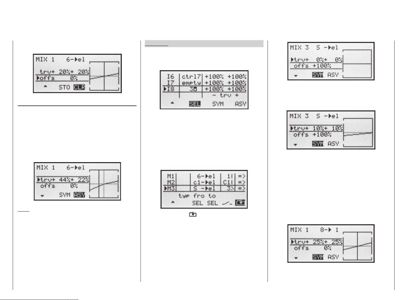
If you were now to reset the offset from -75% to, say, 0%
control travel, the screen would look like this:
Asymmetrical mixer ratios
For many applications it is necessary to set up different
mixer values on either side of the mixer neutral point.
If you set the offset of the mixer used in our example (“6
ELE”) back to 0%, as shown in the picture above,
then select the ASY fi eld and turn the rotary control in
the appropriate direction, the mixer ratio for each direction of control can be set separately, i.e. to left and right
of the selected offset point.
Note:
If you are setting up a switch channel mixer of the “S
NN” type, you must operate the assigned switch to
achieve this effect. The vertical line then jumps between
the left and right sides.
Examples:
1. To open and close the aero-tow release the switch
SW3 has already been assigned to control channel 8
in the »Control settings« menu.
In the meantime you have carried out a few aero-tow
fl ights, which showed that you always needed to hold
in slight up-elevator during the tow. You now wish to
set the elevator servo (connected to receiver output
3) to slight “up” trim when the tow release is closed.
In the screen familiar from page 77 we have set up
the third linear mixer to accomplish this, using the
switch channel “S” as the mixer input. Now move the
selected switch to the mixer OFF position …
… and select the symbol to move to the second
page. Hold the SELECT button pressed in, and use
the right-hand rocker button to select the “Offs” line.
Now press the SELECT button again – and the offset
value jumps to +100% or -100%, depending on the
selected switch position.
Now hold the SELECT button pressed in and use the
right-hand rocker button again to move to the “Travel”
line, where you set the required mixer input – after
moving the selected switch to the mixer ON position.
2. The following example applies to model helicopters:
In the Helicopter program you may wish to assign the
two INC / DEC buttons (CTRL 5 or 6) to the collective pitch trim function. This is the procedure: in the
»Control settings« menu assign one of these two
transmitter controls to input “E8”. Now simply defi ne
a free mixer 8 1 with a symmetrical mixer ratio of,
say, 25%. Due to the internal coupling, this transmitter control now acts equally on all the collective pitch
servos you are using, without affecting the throttle
servo.
80
Free mixers
Page 81
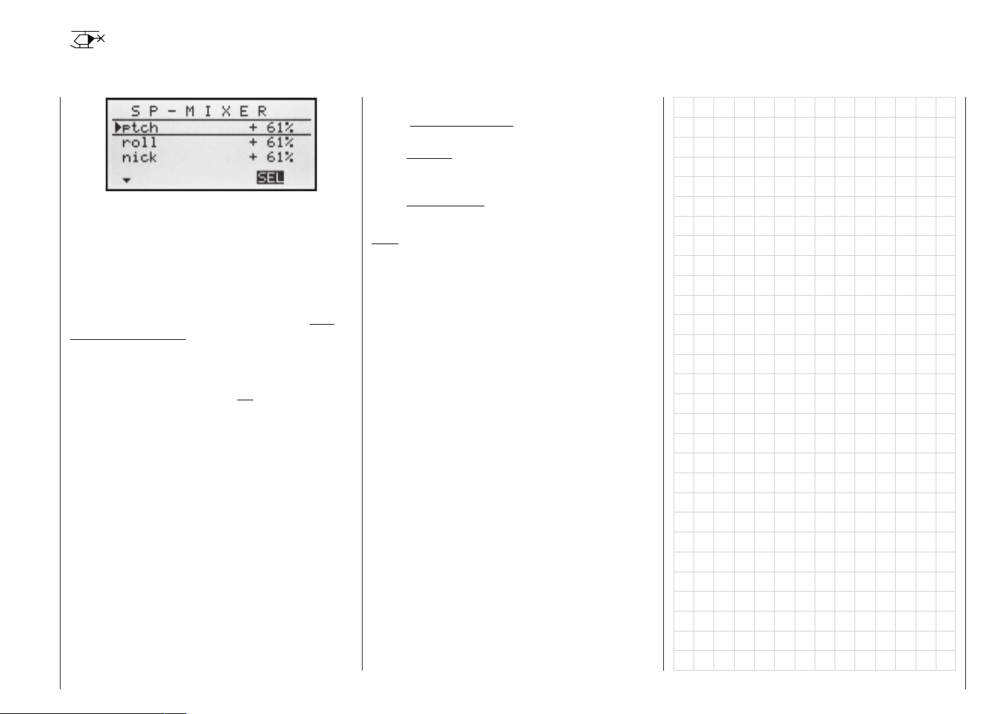
Swashplate mixers
Collective pitch, roll and pitch-axis mixers
In the “Swashplate” line of the »Base settings« menu
you have already defi ned the number of servos which
are installed in your helicopter to provide collective pitch
control; see page 43. With this information the mx-16s
program automatically superimposes the functions for
roll, pitch-axis and collective pitch as required, i.e. you
do not need to defi ne any additional mixers yourself.
If you have a model helicopter which only has a single collective pitch servo, the “Swashplate mixer” menu
point is – of course – superfl uous, since the three
swashplate servos for collective pitch, pitch-axis and roll
are controlled independently of each other. In this case
the swashplate mixer menu does not appear in the multi-function list. With all other swashplate linkages employing 2 ... 4 collective pitch servos, the mixer ratios and
directions are set up by default, as can be seen in the
screen shot above. The pre-set value is +61% in each
case, but the value can be varied within the range
-100% to +100% using the right-hand rocker button, after pressing the SELECT button.
Pressing the CLEAR button resets the mixer input in the
highlighted fi eld to the default value of +61%.
If the swashplate control system (collective pitch, roll
and pitch-axis) does not follow the transmitter sticks in
the proper manner, then the fi rst step is to change the
mixer directions (+ or -), before you attempt to correct
the directions of servo rotation.
HEIM mechanics with two collective pitch servos:
• The collective pitch mixer acts on the two collective
pitch servos connected to receiver sockets 1 + 2;
• the roll mixer also acts on the two collective pitch servos, but the direction of rotation of one servo is reversed, and
• the pitch-axis mixer acts on the pitch-axis servo alone.
Note:
Ensure that the servos do not strike their mechanical
end-stops if you change the servo mixer values.
Swashplate mixers – Model helicopter
81
Page 82

Fail-Safe settings
Fail-safe in the “SPCM” transmission mode
This menu appears in the multi-function list only if you
have selected the SPCM transmission mode. This mode
of operation must be pre-set in the memory-specifi c
»Base settings« menu.
The SPCM transmission mode can be used with all receivers with “smc” in the type designation (smc-19, smc20, smc 19 DS, smc-20 DS etc.).
The operational security of Super Pulse Code Modulation (PCM) is inherently higher than that of simple Pulse Position Modulation (PPM), since the receiver incorporates an integral micro-processor which is capable of
processing received signals even when they are “noisy”.
Only if the received signal is incorrect or garbled due to
outside interference does the receiver automatically replace the invalid signal with the last received correct signal, which is stored in the receiver. This procedure suppresses brief interference caused by local drops in fi eld
strength and similar momentary problems, which otherwise result in the familiar “glitches”.
Caution:
If you are using the SPCM transmission mode, we
strongly recommend that you make use of its safety potential by programming the fail-safe throttle position of a glow-powered model to idle, or the throttle position of an electric-powered model to “motor
stopped”. In this way you ensure that the model is
much less likely to cause havoc if subjected to interference; if this should occur on the ground, the model could otherwise cause serious personal injury or
damage to property.
Fail-safe
82
If you select SPCM transmission mode but have not
yet carried out the fail-safe programming, you will see
a warning message on the screen when you switch the
transmitter on. The message remains on-screen in the
basic display for a few seconds:
Programming
The “Fail-safe” function determines the behaviour of
the receiver when a problem occurs in the link between
the transmitter and the receiver. In SPCM transmission
mode the receiver outputs 1 … 8 can optionally …
1. maintain their current position (“hold mode”):
if interference occurs, all servos programmed to
“hold” remain continuously at the position corresponding to the last valid signal, until the receiver picks up
another signal which it recognises as valid.
2. move to a freely selectable position (“Pos”) if interference occurs.
Use the right-hand rocker button to select the desired
channel 1 to 8 (
der to switch between “hold” ( ) and “position” ( ) mode.
Select the STO fi eld on the screen at bottom right using
the right-hand rocker button, and then simultaneously
move the servos which you wish to set to position mode
) and press the SELECT button in or-
to the desired positions, using the appropriate transmitter controls.
Press the SELECT button to store these positions as
the Fail-safe settings. They will now be transmitted to the
receiver’s memory at regular intervals, so that the receiver can immediately call them up if interference should
strike.
The screen confi rms briefl y that the information has
been stored:
W A R N I N G
You may be tempted to switch the transmitter off
when you are fl ying a model in order to test your
fail-safe settings. Don’t do it! If you do, you run a serious risk of losing the model, as you will be highly unlikely to be able to re-activate the RF signal in
time, since the transmitter always responds with the
security query “RF signal on YES / NO” when switched on.
Page 83

Fail-safe
83
Page 84
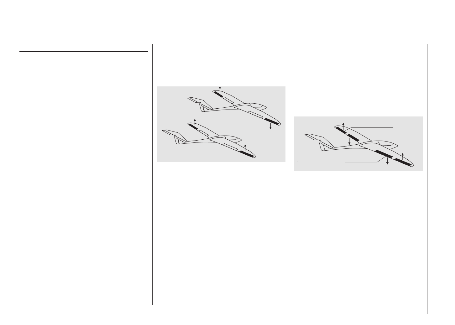
mx-16s programming techniques
Preparation, using a fi xed-wing model aircraft as an example
Programming model data into an mx-16s ...
... is easier than it may appear at fi rst sight.
There is one basic rule which applies equally to all programmable radio control transmitters: if the programming is to go smoothly and the systems work as expected, the receiving system components must fi rst be installed correctly in the model, i.e. the mechanical systems must be fi rst-rate. This means: ensure that each
servo is at its correct neutral position when you fi t the
output lever or disc and connect the linkage to it. If you
fi nd this is not the case, correct it! Remove the output
arm, rotate it by one or more splines and secure it again.
If you use a servo tester, e.g. the Digital Servo Analyzer,
Order No. 763, to centre the servos, you will fi nd it very
easy to fi nd the “correct” position.
Virtually all modern transmitters offer facilities for offsetting the neutral position of servos, but this is no substitute for a correct mechanical installation; this function
is only intended for fi ne tuning. Any substantial deviation from the “0” position may result in additional asymmetry when the signal undergoes further processing in
the transmitter. Think of it this way: if the chassis of a car
is distorted, you may be able to force the vehicle to run
straight by holding the steering wheel away from centre,
but it does not make the chassis any less bent, and the
basic problem remains. Another important point is to set
up the correct control travels wherever possible by using
the appropriate linkage points in the mechanical system;
this is much more effi cient than making major changes
to the travel settings at the transmitter. The same rule
applies: electronic travel adjustment facilities are designed primarily to compensate for minor manufacturing tolerances in the servos and for fi ne adjustment, and not
to compensate for poor-quality construction and defective installation methods.
If two separate aileron servos are installed in a fi xedwing model aircraft, the ailerons can also be employ-
Programming examples: Fixed-wing model
84
ed as fl aps by defl ecting both of them down, and as airbrakes by defl ecting both of them up – simply by setting up a suitable mixer (see the section starting on the
next double page). Such systems are generally more often used in gliders and electric gliders than in power models.
In such cases the servo output arms should be offset
forward by one spline relative to the neutral point, i.e. towards the leading edge of the wing, and fi tted on the
servo output shaft in that position.
The mechanical differential achieved by this asymmetrical installation takes into account the fact that the braking effect of the up-going ailerons increases with their
angle of defl ection, and this means that much less travel is usually required in the down-direction than the updirection.
Similar reasoning applies to the installation of the fl ap
linkage when separately linked fl ap servos are installed,
designed to be used in a butterfl y (crow) system. Here
again an asymmetrical linkage point is useful. The braking effect of the crow system is provided primarily by
the down-movement of the fl aps rather than the up-movement of the ailerons, so in this case the servo output
arms should be angled aft, i.e. offset towards the trailing
edge of the wing, as this makes greater travel available
for the down-movement. When this combination of lowered fl aps and raised ailerons is used, the ailerons should
only be raised to a moderate extent, as their primary
purpose in this confi guration is to stabilise and control
the model rather than act as brakes.
You can “see” the difference in terms of braking effect by
deploying the crow system, then looking over and under the wing from the front: the larger the projected area
of the defl ected control surfaces, the greater the braking effect.
Outboard Ailerons
Inboard Camber-Changing Flaps
This type of asymmetrical installation of the servo output
arms can also make sense when you are setting up split
fl aps or landing fl aps on a power model.
Once you have completed your model and set up the
mechanical systems accurately in this way, you are ready to start programming the transmitter. The instructions
in this section are intended to refl ect standard practice
by describing the basic general settings fi rst, and then
refi ning and specialising them to complete the set-up.
After the initial test-fl ight, and in the course of continued test-fl ying, you may need to adjust one or other of the
model’s settings. As your piloting skills improve and you
gain experience, you might feel the need to try out different control systems and other refi nements, and to cater for these requirements you may fi nd that the text deviates from the obvious order of options, or that one or
other of the options is mentioned more than once.
At this point, just before you start programming the mo-
Page 85

del data, it is worthwhile thinking carefully about a sensible layout of the transmitter controls.
If the model in question is one with the emphasis on “power” – whether the power of an electric motor or internal combustion engine – you will probably encounter few
problems in this matter, because the two stick units are
primarily employed to control the four basic functions
“power control (= throttle)”, “rudder”, “elevator” and “aileron”. Nevertheless, you still have to call up the ...
»Base settings« menu (page 38 … 41)
… and defi ne your preferred throttle direction, i.e. throttle minimum forward (“Idle front”) or back (“Idle rear”), because the program’s default setting is “no” (i.e. no motor)
when you fi rst set up a model memory.
The basic difference between “none” and “throttle min.
front / rear” is the effect of the C1 trim. The trim is effective over the full stick travel if “none” is entered, but it
only affects the idle range if you enter “throttle min. front
or rear”. However, it also affects the “direction of effect”
of the C1 stick, i.e. if you switch from “front” to “rear” or
vice versa, you do not also have to reverse the direction
of the throttle servo. For safety reasons you will also see
a warning message if you switch the transmitter on with
the throttle stick positioned towards “full-throttle” – but
only if you have already set “throttle min. front or rear”.
Your choice of “none” (no motor) or “throttle min. front
or rear” also affects the range of mixers available in the
»Wing mixers« menu. The mixers “Brake NN” are
only present if you choose “none” (no motor), otherwise
they are suppressed.
In addition to these basic matters you will certainly need
to consider carefully how best to control any “auxiliary
functions” featured on your model.
In contrast, if your model is a glider or electric glider the
whole situation may be rather different. The immediate
question is: what is the best way of operating the motor
and braking system? Now, some solutions have proved
to be practical, and others less so.
For example, it is not a good idea to be forced to let go
of one of the primary sticks in order to extend the airbrakes or deploy the crow braking system when your glider
is on the landing approach. It surely makes more sense
to set up switchable functions for the C1 stick (see example 4 on page 92), or to assign the braking system
to the throttle stick, and shift the motor control to a slider – or even a switch. With this type of model the electric motor is often little more than a “self-launching system”, and is used either to drag the model into the sky at
full power, or to pull it from one area of lift to the next at,
say half-power, and for such models a throttle switch is
usually quite adequate. If the switch is positioned where you can easily reach it, then you can switch the motor
on and off without having to let go of the sticks – even
on the landing approach.
Incidentally, similar thinking can be applied to fl ap cont-
rol systems, regardless of whether they are “just” the ailerons, or full-span (combination) control surfaces which
are raised and lowered in parallel.
Once you are satisfi ed that all these preparations have
been completed successfully, programming can begin.
Programming examples: Fixed-wing model
85
Page 86
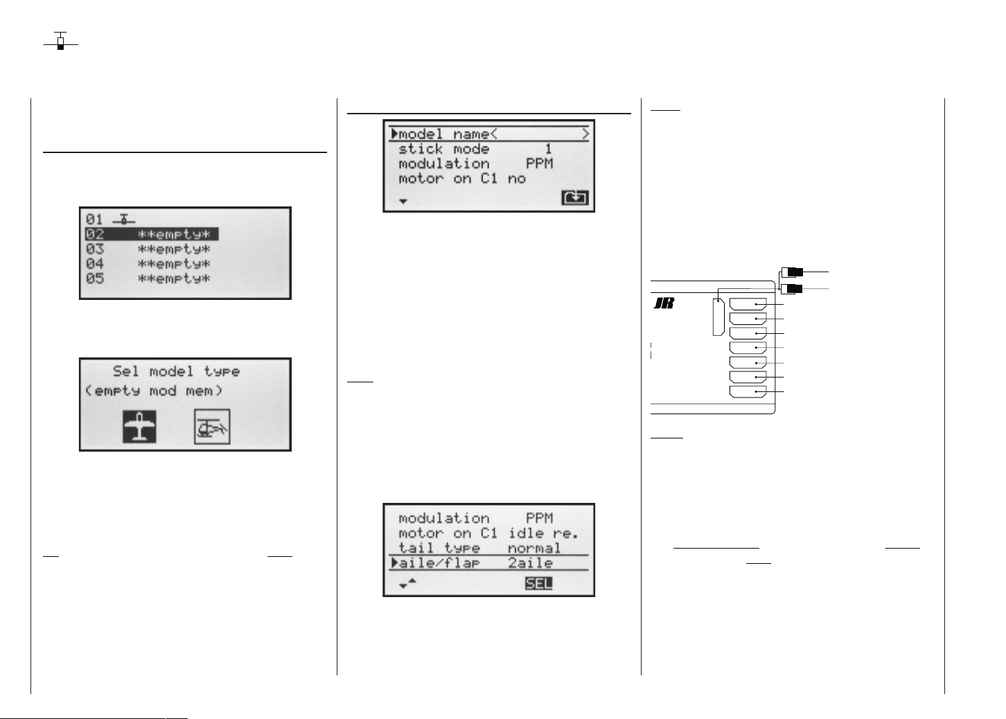
First steps in programming a new model
Example: non-powered fi xed-wing model aircraft
When programming a new model you should start with
the ...
„Select model“ sub-menu (page 36)
... in the »Model memory« menu, where you select a
vacant memory and confi rm your choice by pressing the
ENTER or SELECT button.
Once you have selected a empty model memory, you
are requested to select the type of model to be programmed.
Since in this example we are programming a fi xed-wing
model, we select the fi xed-wing model symbol using the
right-hand rocker button, and confi rm with ENTER or
SELECT. The screen now reverts to the basic display.
Once you have called up the “Model select” option it is
not possible to interrupt the process, i.e. you must choose one or other model type. However, if you make a mistake you can always correct it simply by erasing the model memory.
Now that you have overcome this fi rst hurdle, you can
start programming the actual transmitter settings to suit
the model in the ...
»Base settings« (page 38 … 41)
At this point you can enter the “Model name”, check the
settings for “Stick mode”, “Modulation”, and “Motor at
C1” and change them if necessary:
• “none”: trim works independently of the stick position.
• “Throttle min. front or rear”: C1 trim works on idle range (forward or back) only. If the throttle stick is in the
“full-throttle” direction when you switch the transmitter on, you will be warned of this with the message
“Throttle too high”.
Note:
Selecting “motor” or “no motor” also affects the range of
mixers available in the »Wing mixers« menu. For this
reason we shall fi rst consider “none” (no motor) in the
following programming example.
In the next two lines you select the basic arrangement
of the servos in the model, and inform the transmitter of
your choice:
Tail type: “Normal”, “V-tail”, “Delta / fl ying wing”
or “2 elev sv”
Ailerons / fl aps: 1 or 2 aileron servos and 0 or 2 fl ap
servos
Note:
If your model is fi tted with only one camber-changing
fl ap servo, you should still select “2FL”. Later, in the
»Wing mixers« menu (see page 61), you should select the “Ail fl ap” mixer and set it to 0%. You can still
exploit all the other mixers available at that point in the
usual way.
At this juncture – if not before – you should check that
the servos are connected to the receiver in the standard
Graupner sequence:
Y-lead, Order No. 3936.11 or 3936.32
Best.-Nr.
7052
RO-SUPERHET
0-282/182-191
S C A N
Hz/35MHz-B-Band
Made in Malaysia
FM
! #
8/Batt.
7
6
5
4
3
2
1
Right fl ap servo
Flap servo or left fl ap servo
Right aileron servo
Rudder servo or V-tail
Elevator servo or V-tail
Aileron servo or left aileron servo
Airbrakes or throttle / speed controller
Battery
Auxiliary function
Notes:
If you set up a V-tail, but the “up / down” and / or “left /
right” functions work the wrong way round, please refer to the table in the right-hand column on page 30. The
same procedure can be used if you set up fl aperons
(superimposed ailerons and fl aps), and they work the
wrong way round.
The following settings apply to a model with a “normal”
tail and no motor (“none”); if your model has a V-tail the
settings can be adopted virtually unchanged. However,
if the model is a delta or fl ying wing, the situation is not
quite so straightforward. A special programming example covering this model type will be found in the section
starting on page 97.
Programming examples: Fixed-wing model
86
Page 87

»Servo settings« (page 48)
In this menu you can set various parameters relating to
the servos, i.e. “direction of rotation”, “neutral setting”
and “servo travel”, to suit the requirements of the mo-
del.
By “requirements” we mean adjustments to servo centre and servo travel which are needed to compensate
for minor tolerances in servos and slight inaccuracies on
the model.
Note:
The facilities provided in this menu for setting asymmetrical servo travels are not intended for differential travel
on ailerons and / or camber-changing fl aps. There are
functions designed specifi cally for this in the »Wing mi-
xers« menu.
Once you have completed the settings described so far,
a fi xed-wing or powered model aircraft (the latter if you
state the idle direction of the throttle stick in the “Motor
at Ch1” line of the »Base settings« menu) will, in principle, fl y.
However, there are no “refi nements” in this set-up, and
it is the refi nements which will give you more long-term
fun in your fl ying. Assuming that you are already capable of controlling your model safely, it’s time to get a taste of these extra facilities; to this end we now move on
to the ...
»Wing mixers« (page 61 ... 65)
Note:
This menu will show a varying range of options depending on the information you have entered in the »Base
settings« menu.
Of particular interest at the moment are “Aileron differential” and the “Aileron rudder” mixer, in some ca-
ses the combi-switch (coupled aileron and rudder) and
perhaps the mixers “Brake aileron” and “Brake
fl ap”.
As already described in detail on page 62, the purpose
of “aileron differential” is to eliminate adverse yaw.
When a model aircraft turns, the down-going aileron produces more drag than the up-going one if both move through the same angle, and this causes the model to yaw
in the opposite direction to the turn. This can be eliminated by setting differential servo travel. A value between
20% and 40% is usually a good starting point, but the
“perfect” setting nearly always has to be established by
practical testing.
The same applies to the “Flap differential” option if your
model also features two camber-changing fl ap servos,
assuming that the fl aps are also to be used as ailerons,
e.g. using the “Ail fl ap” mixer.
The “Aileron rudder” mixer serves a similar pur-
pose, but also makes many models generally easier to
handle when turning. A value of around 50% is usually a practical starting point. However, it is advisable to
be able to switch this function off, particularly if you have
ambitions as an aerobatic pilot; this is done by assigning
a physical switch to the mixer.
Setting up a “Brake elevator” mixer is usually only
necessary if your model suffers a marked pitch trim
change (model balloons up or dives) when you deploy
any form of braking system. This problem usually only
arises if ailerons are set to defl ect “up” for braking, or
are used in combination with a butterfl y (crow) system.
If you set up such a mixer it is important to test the setting at a safe height, and adjust the trim compensation if
necessary.
If you have selected “2AIL” or “2AIL 2FL” in the “Aileron /
Flap” line of the »Base settings« menu …
… and if you wish to be able to defl ect both ailerons up
using the throttle / brake stick (C1), then a suitable value
should be entered in the “Brake aileron” line.
Programming examples: Fixed-wing model
87
Page 88

In principle the same applies to the “Brake fl ap” line
if you have selected “2AIL 2FL”, although the set value
should ensure that the fl aps defl ect as far as possible in
the downward direction when the brake stick is operated. It is important to ensure that the servos do not strike
their mechanical end-stops.
If the ailerons are set up to act as simple brakes, or as
part of the braking arrangement in a butterfl y (crow) system, then you should always enter a value for “differen-
tial reduction” (see page 65) – setting 100% is the safe
option here!
Differential reduction means that aileron differential is
suppressed proportionally when you operate the airbrake stick. The purpose of this is to increase the down-going aileron travel on the landing approach, with the aim
of improving aileron response.
If the wing is equipped with two camber-changing fl ap
servos in addition to two separately actuated ailerons, then the “Aileron fl ap” mixer transfers the ai-
leron movements to the fl aps; we suggest that the fl aps
should not follow the movement of the ailerons to a greater extent than about 50%.
Note:
If you have only installed one fl ap servo, then leave this
mixer at 0%.
The “Flap aileron” mixer works in the opposite direc-
tion; depending on the layout of the model we suggest
values between about 50% and 100% for this option.
The fl aps are controlled using the switch assigned to the
Programming examples: Fixed-wing model
88
input “E6”, or the INC / DEC buttons (CTRL 5 and 6).
Note:
We strongly recommend that you reduce the travel of
the fl aps in the »Control settings« menu, as this gives fi ner control of the fl ap positions using the selected
transmitter control.
The remaining options in the »Wing mixers« menu are
designed to provide further fi ne-tuning of multi-fl ap wing
systems, and are largely self-explanatory.
When you have completed the model-specifi c settings
up to this point, you are probably ready to consider the
model’s fi rst fl ight. At this juncture you should certainly take the time to carry out a series of “dry runs”, i.e.
check all the settings thoroughly while the model is still
on the ground. Remember that a serious programming
error may damage more than just the model. If you are
not sure of any point, ask an experienced model pilot for
advice.
If during the test phase you realise that one or other of
the settings needs to be changed in order to tailor the
model’s control response to your preferences – perhaps
the servo travels are too great or too small overall – then
we suggest that you turn to the following menu ...
»Dual Rate / Exponential« (page 56)
... in order to adjust the overall set-up to suit your requirements and fl ying style.
Dual Rates are used to adjust the magnitude of the
stick’s effect (see page 56). However, if it is only the
model’s control response around neutral which is too powerful for comfortable fl ying, i.e. the maximum travels
are acceptable, then “Exponential” can be employed, either instead of Dual Rates or in addition to them. If a physical switch is assigned to this function, you can switch
between two Dual Rate / Expo settings while the model
is fl ying.
Page 89

Programming examples: Fixed-wing model
89
Page 90
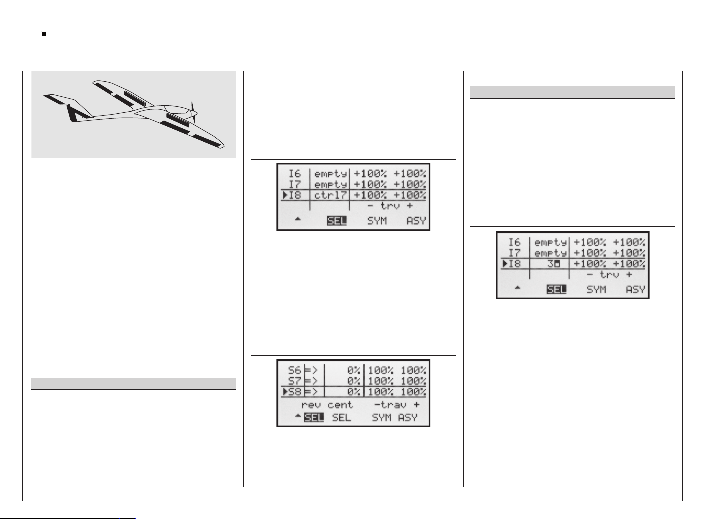
Expanded programming: including an electric power system
An electric power system can be controlled in various
ways. The simplest method of including such a power
plant in a model program is to use the throttle / brake
stick (C1). However, in the preceding programming instructions we have already reserved the C1 transmitter
control for the airbrakes, which means that we have to
explore other possibilities for controlling the motor: one
is to use the switchable solution described in the section
starting on page 92, and another is to use an alternative transmitter control. A suitable option is the three-position switch “SW 6/7”, and another is the rotary proportional control “CTRL 7”, located at top left of the transmitter. (The two INC / DEC buttons – CTRL 5 and 6 – are
less suitable, as you would fi nd it diffi cult to cut the motor quickly enough in an emergency.) However, another
alternative would be one of the two-position switches.
The main reason for your choice ought to be that the
switch is within easy reach of your fi ngers, as this makes
it much easier to hand-launch your model.
Example 1
Using the rotary proportional control CTRL 7
If this transmitter control is used, the set-up is extremely easy. All you have to do is connect the speed controller to any of the receiver servo sockets 5 … 8 which is
vacant.
However, please bear in mind that outputs 2 + 5 and 6 +
7 may already be linked together, depending on the mo-
Programming examples: Fixed-wing model
90
del type you have selected and the number of aileron
and fl ap servos in your model.
Connect your speed controller to the next vacant input,
and assign the rotary proportional control (CTRL 7) to
the selected input – for example, “E8”. This is accomplished in the menu …
»Control settings« (page 50)
Hold the SELECT button pressed in, and use the righthand rocker button to select the desired line. A further
press on SELECT activates “Switch / transmitter control
assignment”. Now turn the knob of the rotary proportional control. After a brief delay the entry “Transmitter control 7” will appear in the highlighted fi eld.
In the third column you can adjust servo travel to suit the
speed controller you are using; alternatively you could
use the “Servo travel” column in the …
»Servo settings« (page 48)
The last stage is to check the settings, so move to the
basic display and then on to »Servo display«. In the
“OFF” position of the rotary control CTRL 7 the control channel you have selected – in our example this is
channel “8” – should be at -100%, and at the “full-thrott-
le” setting at +100%.
Example 2
Using a two-position switch, SW 1 … 4
This variant implements a pure ON / OFF function,
and results in an “abrupt “ motor start-up … unless the
speed controller you are using features what is known
as a “soft start” function.
At the receiving end you need either a simple electronic
switch or – if you want a smoother motor start – a suitable speed controller.
The settings for this arrangement are entered in the …
»Control settings« (page 50)
First check which receiver socket (5 or higher) is available for you to connect your speed controller. If you
have assigned two aileron servos in the »Base set-
tings« menu, and if you have not connected any other
auxiliary function, then this would be channel 6; if your
model features two aileron servos and two fl ap servos,
then channel 8 would be available for connecting the
speed controller; the latter option is the one we will use
in this example.
Hold the SELECT button pressed in, and use the righthand rocker button to select the desired line in the
menu. Press SELECT again to activate “Switch or transmitter control assignment”. Now move the selected
switch from the “OFF” position to the “ON” position. The
highlighted fi eld now shows the switch number together
with a symbol which shows the direction of switching.
Page 91
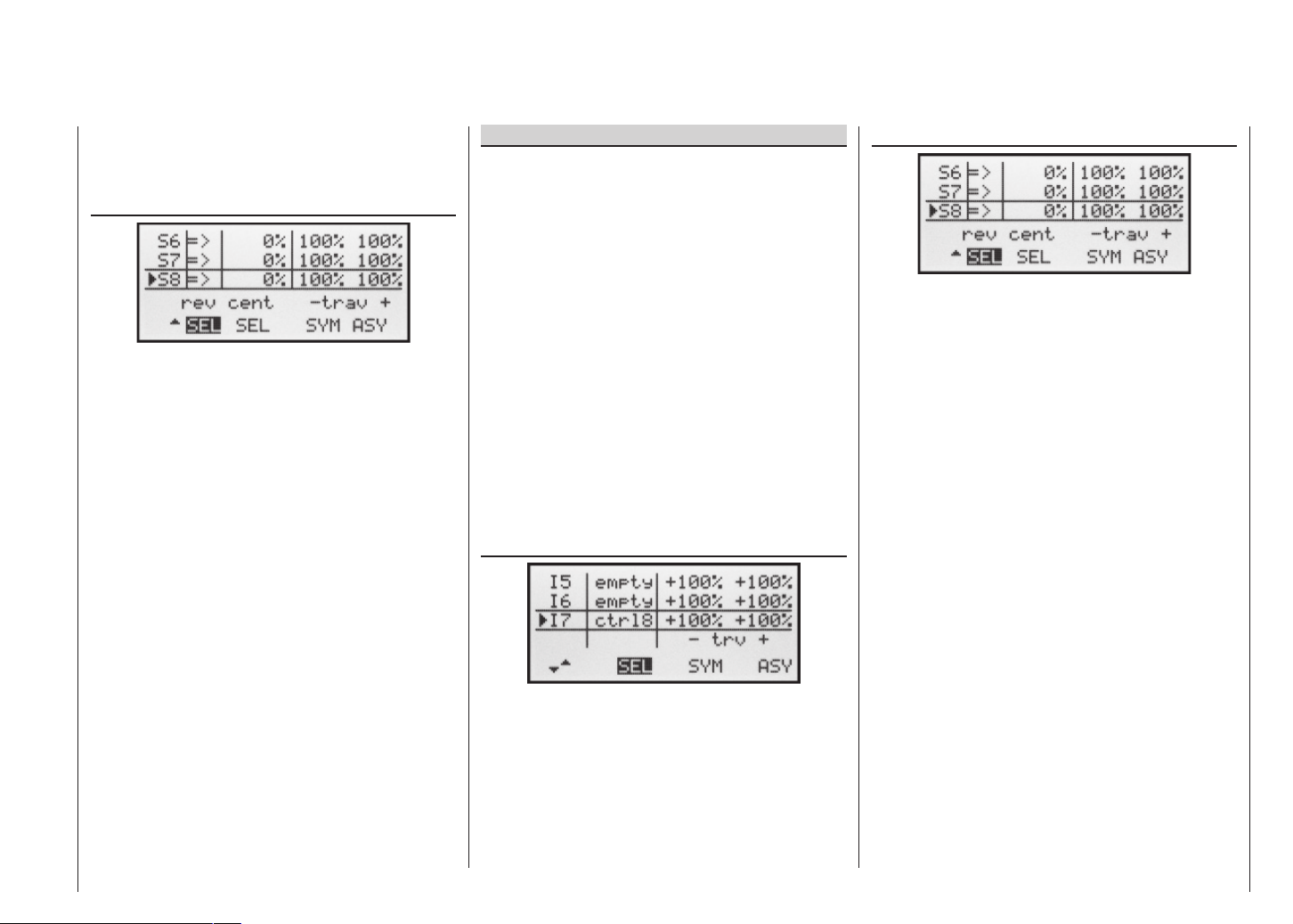
In the third column you can adjust servo travel to suit the
speed controller you are using; alternatively you could
use the “Servo travel” column in the menu …
»Servo settings« (page 48)
The last stage is to check the settings, so move to the
basic display and then on to »Servo display«. In the
“OFF” position of the switch, the control channel you
have selected – in our example this is channel “8” –
should be at -100%, and at the “full-throttle” setting at
+100%.
Example 3
Using the three-position switch SW 6/7
This variant implements a three-stage solution for switching an electric motor on and off, and results in an “abrupt “ motor start-up … unless the speed controller you
are using features what is known as a “soft start” function.
At the receiving end you need a suitable speed controller.
First check which receiver socket (5 or higher) is available for you to connect your speed controller. If you
have assigned two aileron servos in the »Base set-
tings« menu, and if you have not connected any other
auxiliary function, then this would be channel 6; if your
model features two aileron servos and two fl ap servos,
then channel 8 would be available for connecting the
speed controller; the latter option is the one we will use
in this example.
Move to the menu …
»Control settings« (page 50)
»Servo settings« (page 48)
The last stage is to check the settings, so move to the
basic display and then on to »Servo display«. In the
(upper) “OFF” position of the three-position switch the
control channel you have selected – in our example this
is channel “8” – should be at -100%. If you now move
the switch to the centre position, the bar should be in the
middle, and at the (lower) “full-throttle” setting it should
be at +100%.
Hold the SELECT button pressed in, and use the righthand rocker button to select the desired input. Press SE-
LECT again to activate “Switch / transmitter control assignment”. Now move the switch SW 6/7. The highlighted
fi eld now shows “Transmitter control 8”.
In the third column you can adjust servo travel to suit the
speed controller you are using; alternatively you could
use the “Servo travel” column in the menu …
Programming examples: Fixed-wing model
91
Page 92

Controlling the electric motor and butterfl y (crow) system using the C1 stick
(Butterfl y / crow system as landing aid: ailerons up, fl aps down)
Example 4
Before we start the programming of this fourth example,
and turn our attention to expanding the basic programming we have already discussed, we need to consider
briefl y the position of the throttle / brake stick at “motor
OFF” or “brake OFF”. Usually the C1 stick is moved forward to open the throttle, and back to extend the brakes.
However, if you adopt this “classic” confi guration, and
switch, say, from “motor OFF” (stick “back”) to the braking system, “full brake” would immediately be applied,
and vice versa: if you switch from “brakes retracted” to
power, this would instantly switch to “full power”.
These inter-connected effects are defi nitely not desirable, and to avoid them we recommend that you position the “zero point” of both systems so that they coincide. With the mx-16s system the offset point of the fi xedwing mixer “Brake NN” (this mixer is also required),
is fi xed at “stick forward”, so the following programming
example shows how to position “motor OFF” and “brake
OFF” together, at “front”.
In the menu …
»Base settings« (page 38 ... 41)
leave the “motor at C1” line at “none”, or change to
this setting if necessary. This is essential, otherwise the
“Brake 1 NN” mixers which we need will be suppressed in the »Wing mixers« menu.
Important note:
As it is essential to set the motor to “none”, this also
automatically disables the “Throttle too high” poweron warning! For this reason please take great care
to set the C1 stick to the correct position before you
switch on the receiving system.
The next step is to ensure that the motor is switched off
“forward”, and is switched on when the C1 stick is moved “back”, i.e. towards the pilot’s body.
To achieve this you may have to move to the menu …
»Servo settings« (page 48)
and reverse the direction of servo 1.
For safety’s sake you should check this setting now, before you continue with the programming procedure.
Take the transmitter and model to a location where it
is safe to run the motor. Switch the transmitter on, and
move the C1 stick fully forward. Hold your model fi rmly,
or ask a friend to hold it for you. Check that the propeller is free to rotate without causing havoc, then prepare
your model for use.
If the motor does not run in the “stick forward” position,
everything is in order. However, check the system anyway by gradually moving the stick back towards you until
the motor begins to run. Stop the motor, then switch off
the receiving system in the model and fi nally switch off
the transmitter.
Note:
If the motor does not start, or spins in the wrong direc-
tion, there are other problems which you must correct
before you resume programming. For example, check
the wiring of your motor, and refer to the operating instructions supplied with your speed controller.
Once you are confi dent that the direction of the C1 stick
is “correct” as far as the motor is concerned, the next
step is to ensure that its effect on the motor can be switched on and off, so that you can also control the braking
system. This is carried out in the menu …
»Free mixers« (page 77 ... 80)
… where you need to program a free mixer “C1 C1”.
When you have done this, move to the (switch) column and assign your selected “change-over switch” to
this mixer; for example SW 1. This is done by activating
the switch assignment with a brief press on SELECT,
and moving the switch from “forward” to “back”, i.e. towards you.
With the mixer switched on, move to the second screen
page, and there set a starting point of -100% for the
SYMmetrical mixer value.
Now hold the SELECT button pressed in, and use the
right-hand rocker button to move to the “Offs” line. The
Programming examples: Fixed-wing model
92
Page 93

SYM and ASY fi elds are now replaced by STO and
CLR. With the STO button highlighted, move the C1
stick to the “front” end-point and press the SELECT button: the value to the right of “Offs” now changes from
0% to approx. +100% and the graphic display of the mixer characteristic line displayed on the right also changes accordingly:
Return to the basic display by pressing ESC, then press
SELECT to move to the menu …
»Servo display« (page 27)
… where you can immediately check the effect of the
settings you have entered so far: with the mixer switched
off, the bar display for Channel 1 follows the movement
of the C1 stick. With the mixer switched on it stops – as
shown – at around -100%.
Note:
If you carry out this test with the receiving system
and power system switched on, please take great
care that you operate the change-over switch only
in the “motor OFF” position! If you ignore this, there is a danger that the power system will be severely overloaded by being switched on abruptly, and
it could even suffer damage. For the same reason
you should be careful only to use the change-over
switch at the “motor OFF” setting.
To conclude the programming procedure, move the selected “change-over switch” back to the “motor ON” position, i.e. “forward”; move back to the multi-function menu
and from there to the menu …
»Wing mixers« (page 61 ... 65)
… where you can – assuming that you have not already done this in your general model programming – select the “Brake aileron” line and set the desired aileron travel when the C1 stick is operated in the up direction (“Brake”). In the column press SELECT, then
assign your selected “change-over switch” by moving the
switch from “front” to “rear”.
If your model also features camber-changing fl aps,
and you have therefore selected “2AIL 2FL” in the “Ai-
leron / fl ap” line of the »Base settings« menu, locate
the “change-over switch” you have just operated (in this
case switch 1), move it “forward” again and switch to the
“Brake fl ap” line using the right-hand rocker button,
whilst holding the SELECT button pressed in. You can
now set the desired down-defl ection of the fl aps when
the C1 stick is moved (this fl ap position is termed “crow”
or “butterfl y”; see also page 64), and assign the external
switch which also acts as the change-over switch, as already described.
If you now switch back to the »Servo display« menu
and move just the C1 stick, you will see that the bar
display for Channel 1 either remains at around -100%
while the displays for channels 2 + 5 (and also the fl aps
6 + 7, if set up) follow the stick movement, or the other
way round: when the switch is operated, the latter stay
at around the middle, and only the Channel 1 display
moves.
Programming examples: Fixed-wing model
93
Page 94
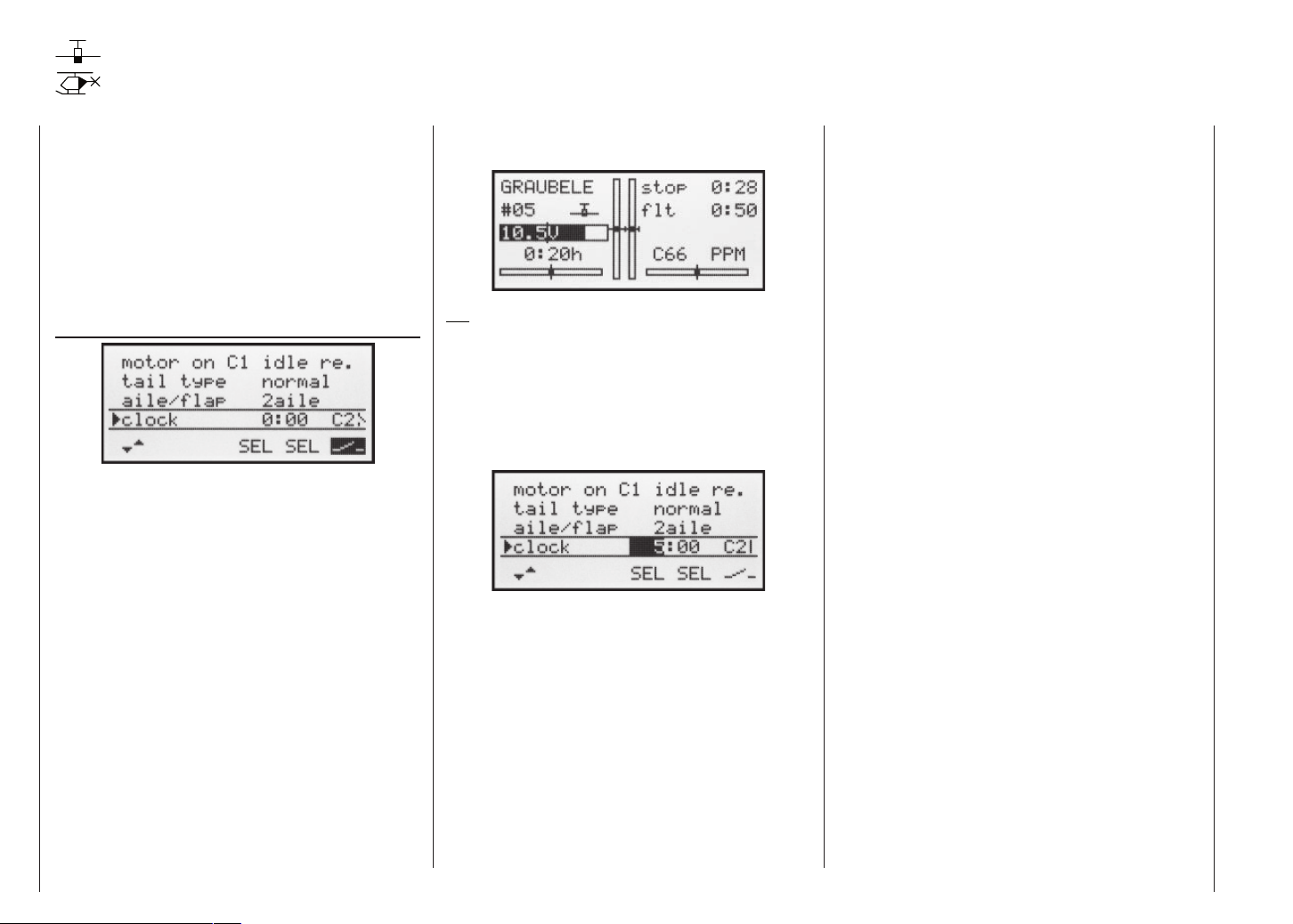
Operating the timers using the C1 stick or a switch SW 1 … 7
If, following on from the model programming described
on the preceding pages, you have decided on Examp-
le 4, or you are using the C1 stick (throttle / brake stick)
to control motor power – independently of this programming example – then you can use the associated control
switch to turn the stopwatch on and off automatically.
To assign this control switch, move the C1 stick to the
Idle position, and then move to the “Timers” line in the
menu …
»Base settings« (page 38 ... 41)
Press the SELECT button to activate the switch assignment, then select the switch symbol and move the
throttle / brake stick from its idle position in the direction of “full throttle”. After a short period the switch “G1l”
or “G2l” will appear on the screen as a switch at a particular position of the C1 stick. If you now move the stick
back towards idle, you will see that the switch symbol
changes again at around 80% of stick travel: between
the “idle position” and the switching point the switch
symbol is “open”, beyond this it is “closed” (“Control switches”: see pages 24 and 25.)
If you now return to the transmitter’s basic display to
check the system, you will see that the stopwatch and
fl ight timer start running when you move the stick past
the switching point in the direction of full-throttle, and
that the stopwatch halts again when you move the stick
back to the idle position.
When the stopwatch is halted, you can stop the fl ight timer by pressing ESC, and then reset both timers to their
starting value by pressing CLEAR … or re-start them by
moving the stick beyond the switching point again.
Tip:
When using an electric motor the motor run is usually limited by the capacity of the battery, and in this case you
would normally set the stopwatch to “count down”. Simply enter the maximum permitted motor run in the “Timer”
column, e.g. “5 min.”. As described on pages 40 and 45,
the piezo buzzer starts to emit warning tones “30 sec”
before “zero”.
With the stopwatch halted, press the CLEAR button in
the basic display, so that the stopwatch switches to the
“Timer” function. The timer can now be started and stopped using the throttle control.
Alternatively, if you control your motor with one of the
switches SW 1 … 4 or 6/7, as described in Examples 2
and 3, you do not need any of the previously described
control switches. All you need to do is locate the switch
which you use to turn your motor on and off, and assign
the same switch to the “Timers”, with the same switching
direction, so that they start running at the same moment
as you switch on the motor.
In contrast, if you have decided on the solution described in Example 1, then unfortunately there is no alternative but to operate the motor and timers separately.
Programming examples: Fixed-wing model
94
Page 95

Using fl ight phases
Within any of the twelve model memories you can program up to three different fl ight phases (states of fl ight),
each incorporating settings which can be entirely different to the others.
Each fl ight phase can be called up by means of a switch.
Flight phases represent the simplest and most convenient method of switching between different model settings in fl ight, programmed for different stages of a typical fl ight, such as normal, thermal, speed, distance etc.
We assume that you have already programmed the model in the transmitter’s model memory, set it up carefully, test-fl own it and trimmed it out properly. First move to
the menu …
»Base settings« (page 38 ... 41)
… and then to the line “Phase 2” and / or “Phase 3”,
where you can either accept the default name or assign a specifi c name to each fl ight phase. The purpose
of this name is just to help you differentiate between the
fl ight phases. It will later appear in the transmitter’s basic
screen display, and also in the »Phase trim« menu.
A physical switch must be assigned so that you can select the different fl ight phases. The ideal unit for switching up to three fl ight phases is the three-position
switch SW 6/7, located at front right on the transmitter;
this is perfect for switching between the three possible
fl ight phases.
Each of the two end-points of this switch should be assigned to one fl ight phase, starting from the centre position. We recommend that the switch direction should
match the phase numbering: as shown in the left-hand
illustration, for example, “Phase 2” is “back” from the
centre position, while “Phase 3” is “forward”.
Select the appropriate line, name, and switch assignment in the “usual” way, i.e. by pressing SELECT and
using the right-hand rocker button.
Note:
The names you assign to the various phases are of no
signifi cance in programming terms – with the exception of Phase 1, which is always assigned the name «normal». As such it is always active even if you disable the
fl ight phases.
For general model fl ying three fl ight phases are usually
quite suffi cient:
• “Launch” or “Thermal” for launch and “staying up”,
• “Normal” for normal conditions, and
• “Speed” for fl ying in “top gear”.
At this point all three phases have been set up and assigned names; however … if you operate the phase switch
you will soon notice that nothing has changed, i.e. all the
settings for the control surfaces, and especially the wing
fl aps, are the same.
To change these settings, call up the menu ...
»Phase trim« (page 60)
… move the phase switch (or switches) to the appropriate position, and enter the desired values in the standard
way using the input buttons.
If you now switch the receiving system on (or move
to »Servo display«) and select the different phases
in turn, you will see a difference in control surface response, or in the bar display for the servos.
Note:
Depending on the information you have entered in the
“Ail / Flap” line of the »Base settings« menu, the “ELEv”
column alone, the “AILe” and “ELEV” columns, or – as
shown above – “FLAP”, “AILE” and “ELEV” may appear
on the screen.
Programming examples: Fixed-wing model
95
Page 96
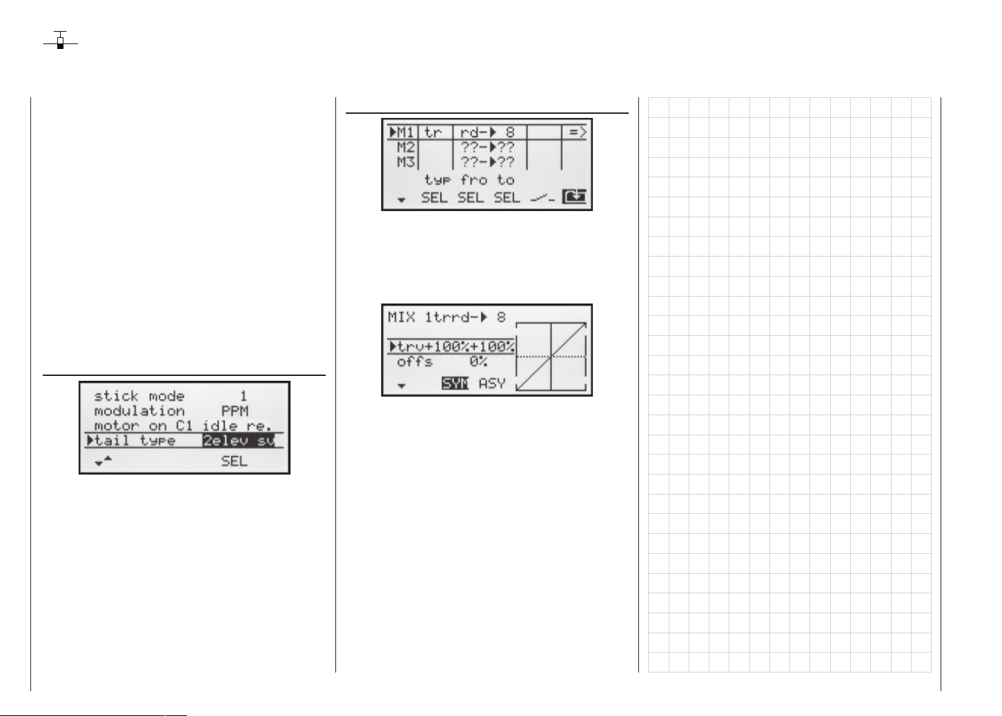
Programming example: servos running in parallel
In some cases a second servo is required to run in parallel with an existing servo; for example, if a second elevator or rudder is to be actuated by a separate servo, or
where a second servo is needed to cope with very high
control forces, or where two servos are required for a
large control surface due to the high torsional forces involved.
This task could be solved simply by connecting both servos together in the model using a conventional Y-lead.
However, this has the drawback that the linked servos
cannot be adjusted individually from the transmitter, i.e.
you forfeit the basic advantage of the computer radio
control system: freely variable servo settings.
For this reason the simplest method of operating two
elevators in parallel (servos 3 + 8) is to use the “Tail”
menu. First move to the menu …
»Base settings« (page 38 ... 41)
… and set “2 elev sv” in the “Tail type” line.
The following example makes use of the »Free mixers«
menu, which offers the advantage of asymmetrical and /
or non-linear curves.
In this example we will connect two rudders “in parallel”.
The second rudder could be connected to receiver output 8, which is not already in use.
The fi rst step is to move to the menu …
»Free mixers« (page 77 ... 80)
… and set up a mixer “Tr rd 8”. In the “Type” column
select the “Tr” setting, so that the rudder trim affects both
rudder servos.
Finally switch to the graphics page and set a SYMmetrical mixer input of +100%:
Here again, for safety reasons it is really essential that
you set input 8 to “free” in the »Control settings« menu.
As an added refi nement, you may want both rudders to
defl ect outwards as part of a braking system controlled
by the C1 stick. This can be accomplished by setting up
two additional mixers “c1 4” and “c1 second rud-
der channel”, with suitable servo travel settings. An offset of +100% is then selected for both mixers, as the
C1 stick is (usually) at its top end-point when the airbrakes are retracted, and the winglet rudders are only required to defl ect outward proportionally when the brakes
are extended.
Programming examples: Fixed-wing model
96
Page 97

Programming examples: Delta and fl ying wing
On page 84, where the section on fi xed-wing model programming starts, you will fi nd general notes regarding
installing and setting up the RC system in a model, and
– of course – this applies equally to deltas and fl ying
wings. The information on test-fl ying and refi ning the settings is also relevant, including the section on programming fl ight phases.
left
right
In their characteristic shape and geometry, deltas and
fl ying wings differ very clearly from “normal” models
even at fi rst sight, but the differences in the requisite
servo arrangement are rather more subtle. The “classic”
model delta or fl ying wing generally has only two control
surfaces, which act both as ailerons (in opposite directions) and as elevators (in the same direction), in a similar way to the superimposed rudder / elevator functions
of a V-tail. More modern designs tend to be more complex; one (or two) inboard control surfaces may be used
purely as elevators, while the outboard ailerons also act
as elevators, but to a reduced extent. If a fl ying wing has
four or even six wing control surfaces, it is certainly feasible nowadays to set them up with camber-changing
fl ap functions and / or even a butterfl y (crow) system.
However, most of these models still rank as “classic” deltas and fl ying wings, and for them the servos should be
connected to the receiver as follows (see also page 30):
Y-lead, Order No. 3936.11 or 3936.32
Best.-Nr.
7052
RO-SUPERHET
0-282/182-191
S C A N
Hz/35MHz-B-Band
Made in Malaysia
FM
! #
8/Batt.
7
6
5
4
3
2
1
Right fl ap servo
Left fl ap servo
Auxiliary function
Rudder (if present)
Right elevon (aileron / elevator) servo
Left elevon (aileron / elevator) servo
Airbrakes or throttle or speed controller
Battery
Auxiliary function
If your delta or fl ying wing is of more “modern” confi guration, the “normal” servo sequence has proved useful;
this arrangement can also be used for canards:
Y-lead, Order No. 3936.11 or 3936.32
Best.-Nr.
7052
RO-SUPERHET
0-282/182-191
S C A N
Hz/35MHz-B-Band
Made in Malaysia
FM
! #
8/Batt.
7
6
5
4
3
2
1
Right fl ap / elevator
Left fl ap / elevator
Right elevon (aileron / elevator)
Rudder (if present)
Elevator
Left elevon (aileron / elevator)
Airbrakes or throttle or speed controller
Battery
Auxiliary function
Regardless of the receiver servo sequence you select,
you should fi rst move to the menu ...
»Base settings« (page 38 ... 41)
… and select the following options in each line:
„Motor in C1“: “No” (no motor): C1 trim acts equally
along the whole travel, or “throttle min.
front / rear”: trim acts only at idle range.
„Tail type“: “Delta / fl ying wing” or “Normal” type
„Aileron / fl ap“: Two ailerons “2AIL” and – if present –
two fl aps “2FL”.
The primary function of these settings is to defi ne the
range of wing mixers which the software will make available. If you select the “Delta / fl ying wing” tail type, the
software automatically superimposes the elevator and
aileron functions. In this case the mixer ratios can be adjusted by varying the Dual Rate settings in the »Dual
Rate / exponential« menu (see page 56).
If you select “Delta / fl ying wing”, all settings of the “NN
elevator” wing mixers in the ...
»Wing mixers« (page 61 ... 65)
… affect the elevator (up / down) function of the two elevon (combined aileron / elevator) servos, as well as the
fl ap / elevator servos.
The fl ap mixer and fl ap differential only appear in the list
if you have entered “2FL” in the “Aileron / fl ap” line of the
”Delta / fl ying wing” model type.
Note:
Even if you have selected “2AIL / 2FL”, the (digital) elevator and aileron trims only affect aileron / elevator (servos 2 + 3). If you wish to circumvent this it is simpler to
program your model as described in the following section.
Programming examples: Delta and fl ying wing
97
Page 98
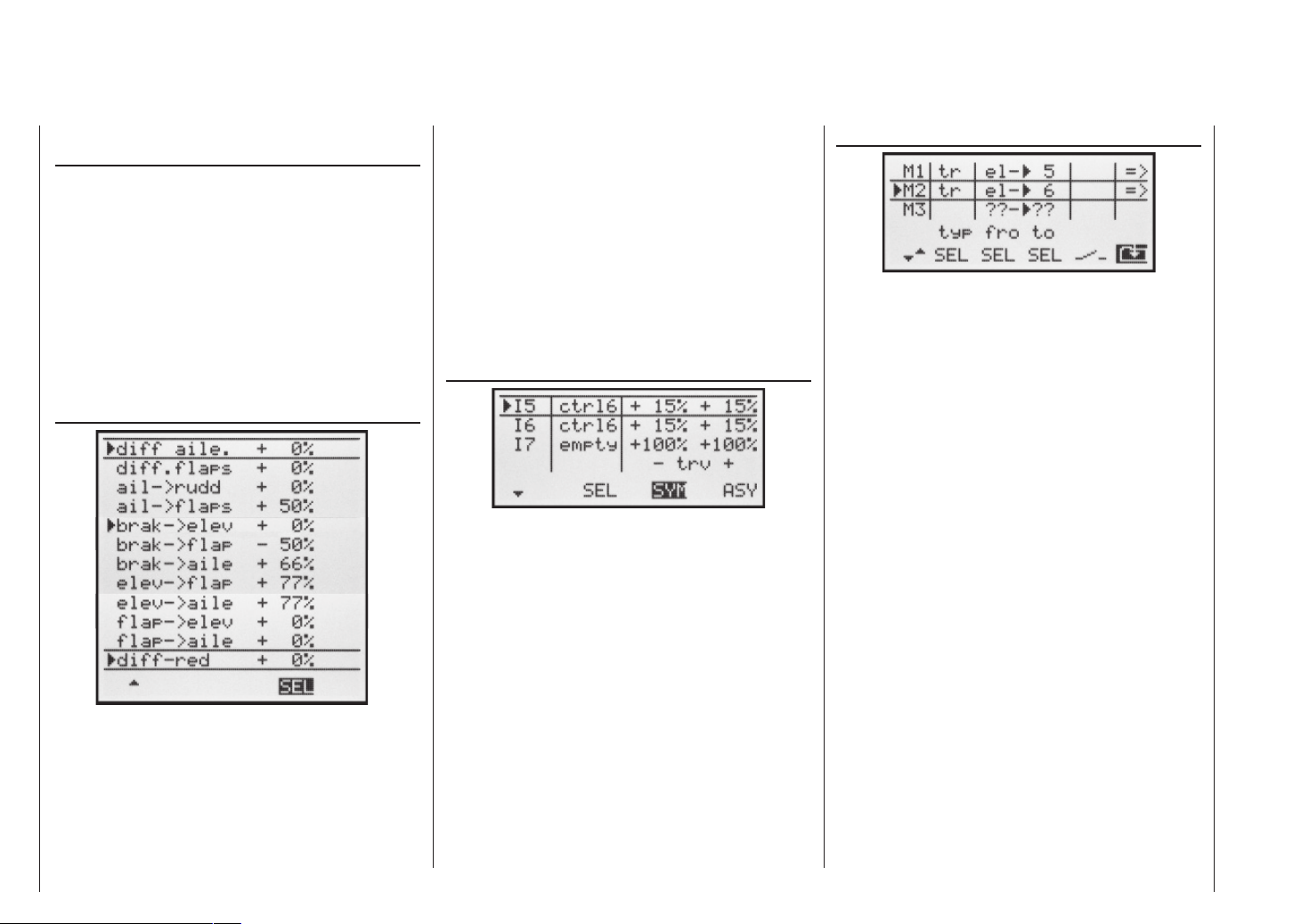
Programming a model delta using the “normal” tail
setting
Alternatively, if you select the “normal” tail type in the
»Base settings« menu, and connect the servos to the
receiver as shown in the lower of the two receiver socket
sequence diagrams on the previous page, then the aileron function of the two elevon servos will work correctly,
but not the elevator function.
In the “normal” tail type you have to force the two aileron servos and the two fl ap servos to move in the same
direction and provide an elevator effect when an elevator command is given. The procedure starts by selecting
the menu ...
»Wing mixers« (page 61 ... 65)
… where you set values other than zero for the Wing mixers “Elevator NN”.
(The following settings are model-specifi c, and you
must check carefully that they work correctly on
your model before accepting them.)
With this set-up the tailless model is considered to be a
“normal” four-fl ap wing (two ailerons and two fl aps), and
Programming examples: Delta and fl ying wing
98
therefore has all the options associated with this wing
type. The method involves the “Elevator NN” mixers,
which were originally intended only for pitch trim compensation and non-standard applications. In this case
they are “abused” by setting higher values than normal,
in order to transfer the elevator signal to the control surfaces of the tailless model.
However, none of the Wing mixers include the digital
trim of the elevator stick – so an alternative has to be
found.
Start by switching to the menu …
»Control settings« (page 50)
… and assign the same transmitter control to the inputs
5 and (if required) 6, e.g. the INC / DEC buttons, CTRL
6. Now move to the “Travel” column and reduce the tra-
vel of the transmitter control for these two inputs symmetrically to around 50%, or even less, because: the lower this value, the fi ner the trim control.
However, if you prefer to use the normal elevator trim lever, set the “Elevator NN” mixers to 0%, and instead
set up free linear mixers to do the job.
This is done by calling up the menu ...
»Free mixers« (page 77 ... 80)
… and setting up one linear mixer “Tr el 5” (for the
simplest case), and possibly “tr el 6”. Move to the
graphics page of this menu to set the required mixer ratios. Check the settings, and above all the direction of effect, in the »Servo display«, or on the model itself, and
change the prefi xes if necessary.
If you carry out the programming as described above,
the ailerons will move in the same direction, like fl aps,
when you move the elevator stick. The effect of the “Tr”
option is that the elevator trim lever also affects the associated mixer when you operate the elevator stick.
Move to the graphics page of this menu to set the required mixer ratios: to obtain the same direction of movement as the wing mixers, you will have to program a
symmetrical value of approximately “-50%”, for MIX 1,
and approximately “+70%” for MIX 2; compare the wing
mixer settings above.
Since another transmitter control is no longer required
for this arrangement, you should disable input 5 and (if
used) input 6 in the second column of the »Control set-
tings« menu; simply set these inputs to “free”.
Many years ago the author operated a model delta with
the mc-20, programmed exactly in this way, with the following additional refi nements: fl ap settings used as trim,
and butterfl y (crow) as landing aid – the latter exploiting
the “Brake aileron” and “Brake fl ap” wing mixers
to provide complete compensation for pitch trim changes. In this case the term “ailerons” means the outboard
wing control surfaces, and “fl ap” the inboard pair of con-
Page 99

trol surfaces.
A modern sweptback fl ying wing can be operated in a si-
milar fashion. These models also feature inboard and
outboard control surfaces: the former forward of the
Centre of Gravity, the latter aft of it. Defl ecting the inboard control surface(s) down increases lift and produces an up-elevator effect. Defl ecting them up creates the opposite effect. In contrast, the outboard ailerons
have the reverse effect: a down-defl ection produces a
down-elevator effect, and vice versa. In this case there
are really no limits to what you can achieve with careful
thought and the sophisticated mixers of the mx-16s.
However, please note that you should be extremely careful when setting differential travel with such a confi guration, regardless of the type of servo arrangement you
are using. This is because differential travels tend to produce an asymmetrical elevator effect on a tailless model, rather than the desired adverse yaw reduction. For
this reason it is advisable to start with a differential setting of 0%, at least for the fi rst few fl ights. When you are
familiar with the model and feel the need to experiment,
it may then be feasible under certain circumstances to
try differential settings deviating from zero.
For larger models it may be advisable to install winglets fi tted with rudders, i.e. small vertical surfaces at the
wingtips. If these are actuated by two separate servos,
they can be controlled as described in the example on
page 96 dealing with “Servos running in parallel”.
You may also want both rudders to defl ect outwards
when a braking system is operated using the C1 stick,
and this can be achieved as follows: if you have selected the “normal” tail type, set up two further mixers “c1
4” and “c1 control channel of the second rudder” with suitable travel settings. The offset should be
+100%, as the C1 stick is usually at the front end-point
when the airbrakes are retracted, and the winglet rudders are required to defl ect outwards proportionally
when the brakes are extended.
Programming examples: Delta and fl ying wing
99
Page 100
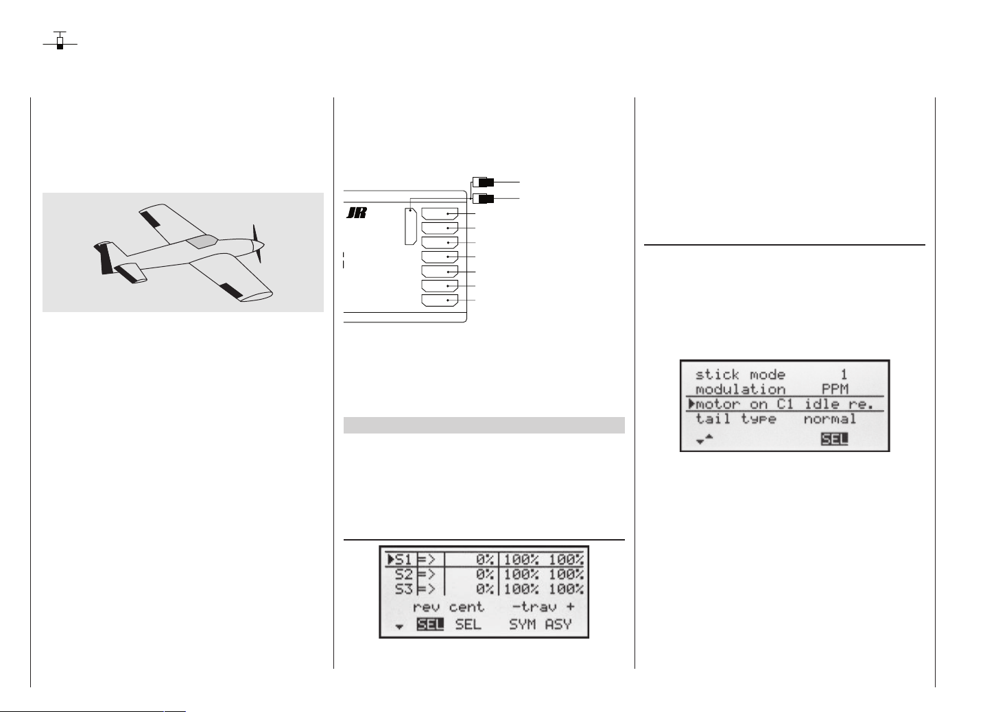
Programming example: F3A model aircraft
F3A models belong to the category of powered fi xedwing model aircraft designed for competition fl ying. They
may be powered by an internal combustion engine or an
electric motor. Electric-powered models are eligible to fl y
in the international F3A “pattern” class, and also in the
F5A electric aerobatic class.
On page 84, where the section on fi xed-wing model programming starts, you will fi nd general notes on installing and setting up the RC system in a model, and – of
course – this applies equally to F3A models, and therefore does not need to be repeated at this point.
If an F3A model is accurately built, it usually exhibits
fl ying characteristics which are almost completely neutral. The perfect aerobatic model has a very smooth but
precise control response, and any movement around
any one of its fl ight axes should not affect the other
axes.
F3A models are fl own using aileron, elevator and rudder
controls. The use of separate servos for each aileron is
almost universal. The fl ying controls are supplemented
by control of motor power (throttle function) and in many
cases a retractable undercarriage. As a result the servo assignment for channels 1 to 5 is no different to the
fi xed-wing models we have already described.
The auxiliary function “Retracts” is usually assigned
to one of the auxiliary channels 6 to 8. Ideally the retracts are operated using a switch without a centre detent, or the momentary button SW 4. An optional “extra”
Programming examples: F3A model
100
– used only if necessary – is mixture adjustment control
for the carburettor. This is generally operated by one of
the two INC / DEC buttons (CTRL 5 or 6) on the transmitter, connected to one of the auxiliary channels not already in use.
Y-lead, Order No. 3936.11 or 3936.32
Best.-Nr.
7052
RO-SUPERHET
0-282/182-191
S C A N
Hz/35MHz-B-Band
Made in Malaysia
FM
! #
8/Batt.
7
6
5
4
3
2
1
Mixture adjustment
Retracts
Right aileron servo
Rudder servo
Elevator servo
Aileron servo or left aileron servo
Throttle or speed controller
Battery
Auxiliary function
When assigning functions to the auxiliary channels at
the transmitter, it is advisable to ensure that the controls
required are within easy reach, since the advanced aerobatic pilot has very little time to think about letting go
of the sticks – especially when fl ying in a competition.
Programming
The basic programming of the transmitter has already
been described in detail in the section starting on page
86, so this section concentrates on tips specifi c to F3A
models.
In the menu ...
»Servo settings« (page 48)
… you can adjust the servo settings to suit your model.
It has proved advisable to use at least 100% servo travel, as precision of control can be perceptibly better if
relatively large servo travels are employed. This should
be borne in mind when building the model and designing the control surface linkages. Any minor corrections
required can be made in the 3rd column during the initial test fl ights.
The next step is to select the menu ...
»Base settings« (page 38 ... 41)
… and activate the idle trim for Channel 1 (normally
“Idle back”; i.e. full-throttle forward). The digital trim now
works at the idle end of stick travel. The “cut-off trim” enables you to switch immediately from the “motor stopped” position to the idle position you have previously
set just by applying a single “click” on the trim lever (see
page 26).
The remaining settings should be adjusted if required to
suit your personal preferences.
You may fi nd it necessary to assign transmitter controls
to particular inputs to operate the retractable undercarriage and carburettor mixture adjustment. This is carried
out in the menu ...
 Loading...