

Page 1

Page 2

Servoweg Anpassung (Travel Adjust)........................... 27
Taumelscheiben Mischer (CCPM-TS).......................... 28
„Motor AUS“ (Throttle Cut)........................................... 29
Autorotation (Throttle Hold).......................................... 29
Gaskurven (Throttle Curve).......................................... 30
Pitchkurven (Pitch Curve)............................................. 31
Statischer Drehmomentausgleich DMA....................... 33
Programmierbare Mischer (1~2).................................. 33
Fail Safe....................................................................... 34
Servoweg Anzeige....................................................... 35
Systemmodus
Systemmodus
Modell-Auswahl (Model Select)....................................36
Eingabe des Modellnamens......................................... 36
Modelltyp Auswahl (Model Type).................................. 37
Modell kopieren (Model Copy)..................................... 37
Modulation.................................................................... 38
Steueranordnung (Stick Mode).....................................38
Taumelscheiben Auswahl (Swash Type)....................... 44
Anhang
Allgemeine Hinweise
Allgemeine Hinweise
Tasteneingaben und Anzeige....................................... 14
Warnungs- und Fehleranzeige......................................14
Hinweise zum Umweltschutz
Das Symbol auf dem Produkt, der Gebrauchsanleitung
oder der Verpackung weist darauf hin, dass dieses
Produkt am Ende seiner Lebensdauer nicht über den
normalen Haushaltsabfall entsorgt werden darf. Es
muss an einem Sammelpunkt für das Recycling von
elektrischen und elektronischen Geräten abgegeben
werden.
Die Werkstoffe sind gemäß ihrer Kennzeichnung wiederverwertbar. Mit der Wiederverwendung, der stofflichen Verwertung oder anderen Formen der Verwertung
von Altgeräten leisten Sie einen wichtigen Beitrag zum
Umweltschutz.
Batterien und Akkus müssen aus dem Gerät entfernt
werden und bei einer entsprechenden Sammelstelle
getrennt entsorgt werden.
Bitte erkundigen Sie sich bei der Gemeindeverwaltung die zuständige Entsorgungsstelle.
Page 3

3
Wenn Sie Anfänger im Bereich ferngesteuerter Modell-
flugzeuge, -schiffe oder -autos sind, sollten Sie unbe-
Anwendungsbereich
vom Hersteller vorgesehenen Zweck, für den Betrieb in
werden. Eine anderweitige Verwendung ist verboten.
Technische Defekte elektrischer oder mechanischer Art
verletzen können!
Alle durch einen Motor angetriebenen Teile wie Luft- und
tigkeit und anderen Fremdteilen. Setzen Sie diese
wenn sie wieder trocken sind, nicht mehr verwenden!
terungen oder Landestöße direkt auf ihn übertragen
werden. Beim Einbau der Empfangsanlage in ein Modell
Anschlusskabel zu den Servos und zum Stromversor-
verlegen.
Page 4

Vibrationsschlägen einigermaßen geschützt.
wichtig ist, dass alle Ruderhebel ihre vollen Ausschläge
werden.
Vergaserküken ganz geschlossen wird, wenn Steuer-
Achten Sie darauf, dass keine Metallteile, z. B. durch
falsch, mit der Antenne des Senders auf das Modell zu
flussen. Bei gleichzeitigem Betrieb von Fernlenkanlagen
wissern Sie sich vorher davon, dass Sie als Einziger auf
Immer zuerst den Sender einschalten und dann erst
den Empfänger.
Immer zuerst den Empfänger ausschalten und dann
erst den Sender.
Wenn diese Reihenfolge nicht eingehalten wird, also der
jedoch auf „AUS“ steht, kann der Empfänger durch an-
werden. Das Modell kann sich in der Folge unkontrolliert
Der auslaufende Kreisel erzeugt oftmals so viel Span-
nung, dass der Empfänger gültige Gas-Signale erkennt.
Daraufhin kann der Motor unbeabsichtigt anlaufen!
Vor jedem Einsatz korrekte Funktion und Reichweite
während ein Helfer das Modell festhält.
Autobahnen, Wegen und Plätzen etc..
terien aufzuladen (Explosionsgefahr).
Alle Akkus müssen vor jedem Betrieb geladen werden.
Trennen Sie immer alle Stromquellen von ihrem Modell,
wenn Sie es längere Zeit nicht mehr benützen wollen.
Page 5

5
weniger stören. In Modellen mit Elektroantrieb muss
jeder Motor daher sorgfältig entstört werden.
Weitere Details zu den Entstörfiltern siehe GRAUPNER
Auch Zündungen von Verbrennungsmotoren erzeugen
Achtung:
jeweiligen Ländern zugelassenen Frequenzen /
jeweiligen Behörden entsprechend geahndet.
wenden, die von GRAUPNER auf Tauglichkeit, Funktion
werden kann.
Verpflichtung der Fa. GRAUPNER zur Leistung von
Vorschriften wegen Vorsatzes oder grober Fahrlässigkeit
Page 6
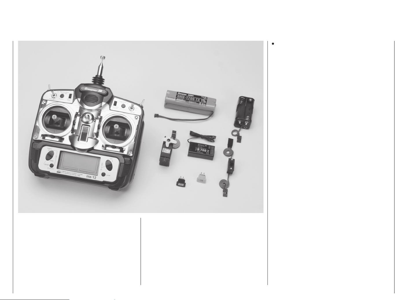
Durch Spitzentechnologie optimiertes Computer-
Universell einsetzbares Fernlenksystem voll ausge-
baut
F3E-, Delta- und V-Leitwerk-Modelle. Auf 6 Steuer-
funktionen, 4 proportional, trimmbar, 2 schaltbar, voll
ausgebaut
des Betriebs-MODES 1-4 (Gas rechts/links).
Alle Mixer-, Einstell- und Reverse- Speicherdaten
werden automatisch mit umgestellt.
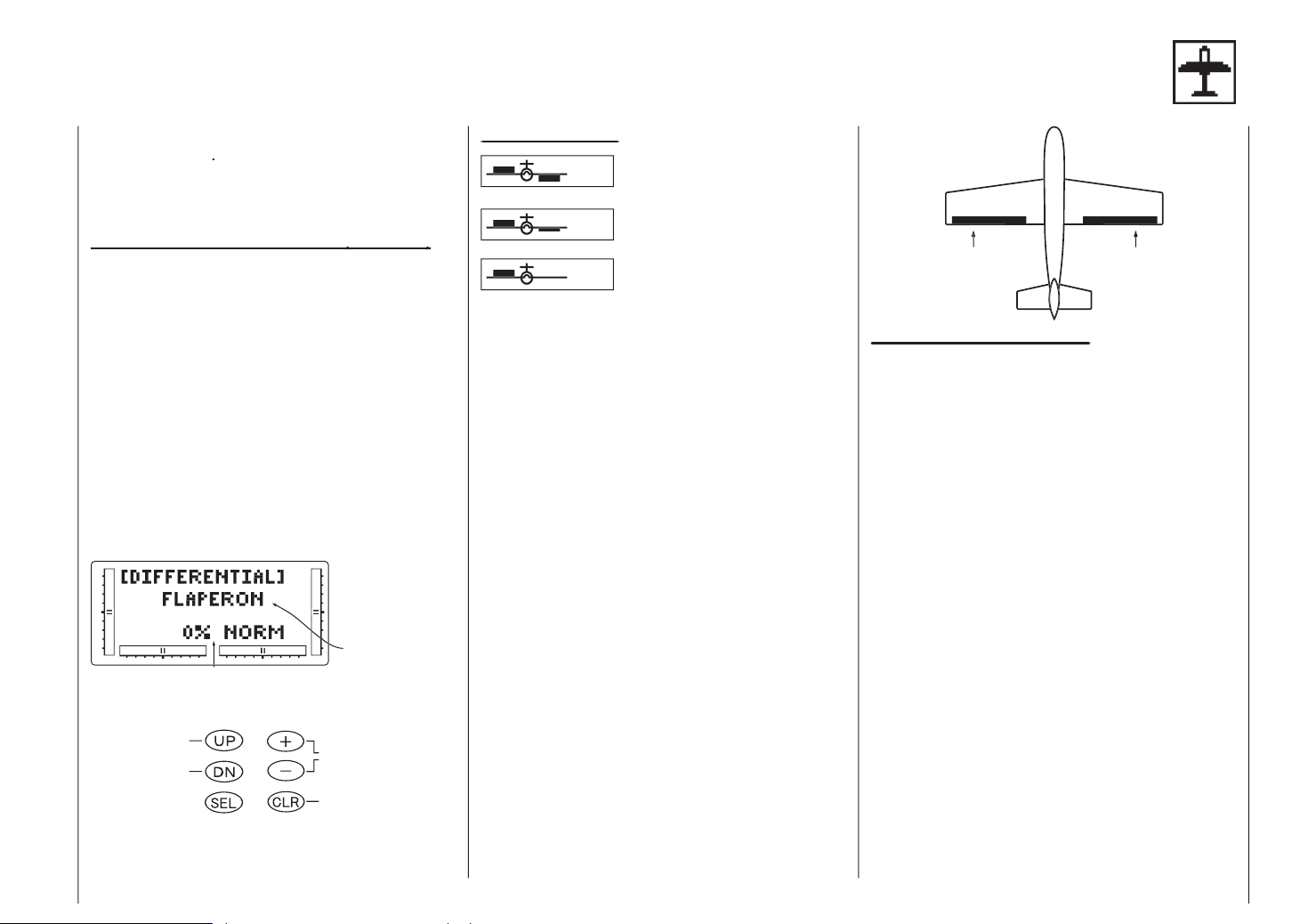
DIFFERENTIAL-FLAPERON
(Querruder-Differential-Mix)
ELEVON (Delta, Querruder-Höhe-Mix),
V-TAIL (V-Leitwerk, Höhe-Seite-Mix)
SWASHPLATE TYPE (Taumelscheibe 1 Servo, 2
Servos 180°, 3 Servos 120°, 3 Servos 90°
Programm- und Einstellparameter
SPCM-Empfangsanlagen
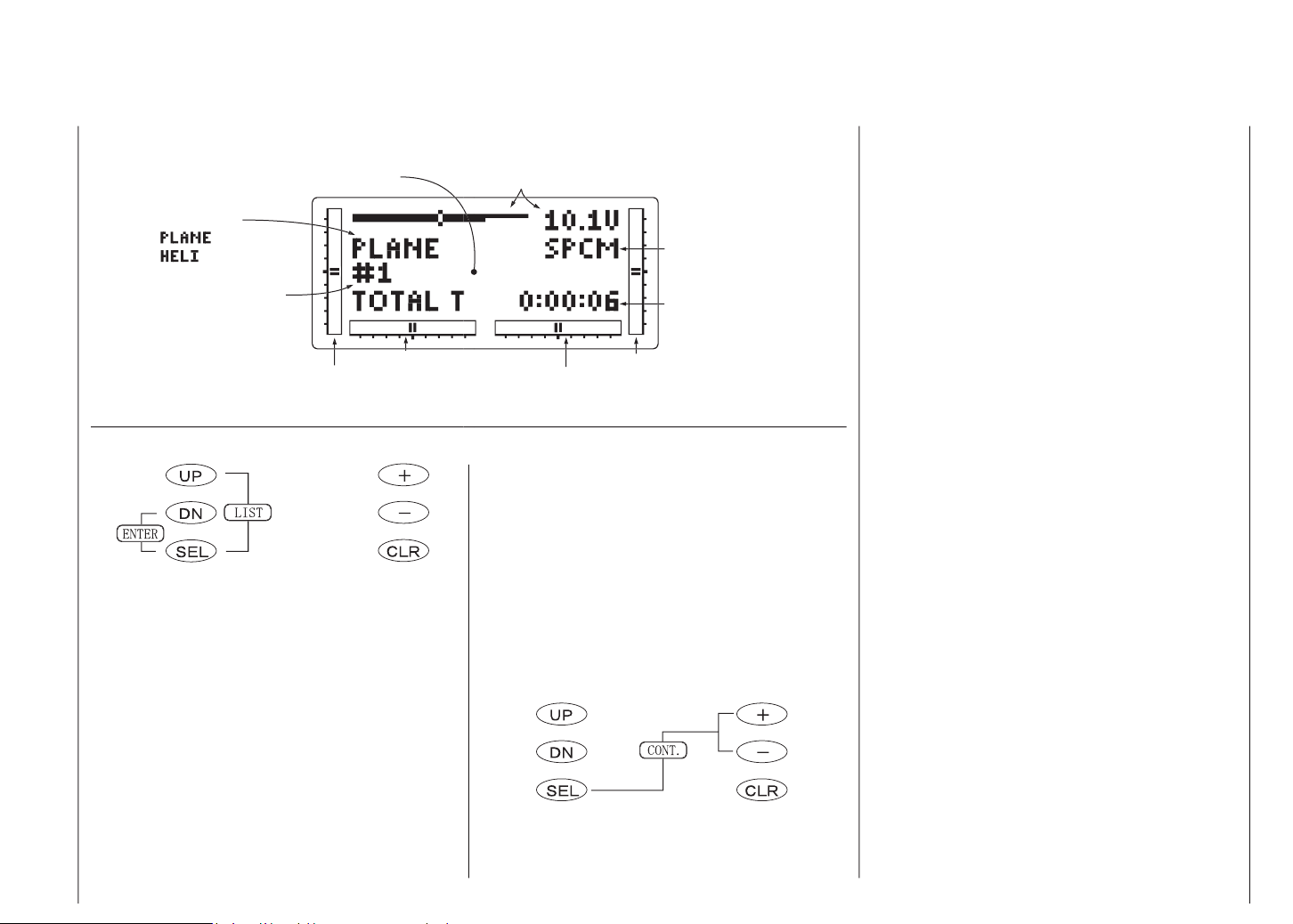
eine präzise Kontrolle, auch bei grellem Sonnenlicht,
der im Senderdisplay angezeigten Funktionen, z.B.
Eingabedaten von Mixer-Funktionen, Einstellwerten,
Drehrichtungen, Trimmwerten, Programminformation
bei Multi-Funktionsprogrammen sowie der Betriebs-
spannung des Senderakkus.
Vorhandene Mixsysteme sowie exakt einstellbare
End- und Mittenpositionen ermöglichen die Verwen-
dung des Systems für den anspruchsvollen Anwen-
der im Flug-, Schiffs -und Car-Modell-Bereich.
Fernsteuersystem mit 10 Modellspeichern.
Hohe Funktionssicherheit durch modernes Computersystem. Problemlose Programmierung durch
vereinfachte Rotary-Programmiertechnik.
Ein kontrastreiches Grafik-Display ermöglicht die
präzise Anzeige von Batteriespannung des Senderakkus, Modulationsart, Modelltyp, Modellnamen,
Modellspeicher-Nummer, Einstelldaten, Drossel- und
Pitch-Kurven sowie Modellbetriebszeit.
Page 7
grammierbar
und 125% für 3 Servofunktionen programmier- und
schaltbar
ruder- Mix)
ler Servos und Anpassung älterer Fabrikate oder
Servos mit ungenormter Mitte
TRAVEL ADJUST getrennte Weg-Verstellung für
beide Endausschläge aller Servos. Verstellbereich
von 0 - 150%. Mit der neuartigen Einstellung ist
es möglich, symmetrische und asymmetrische
Servowege zu programmieren, z.B. bei Verzug einer
Tragfläche o.ä. Anwendungsfällen.
für Sender- und Back-Up-Lithium-Batterie
Akku 8 NH-1700 TX, Empfänger R 700 der entspre-
*Nur für Export!
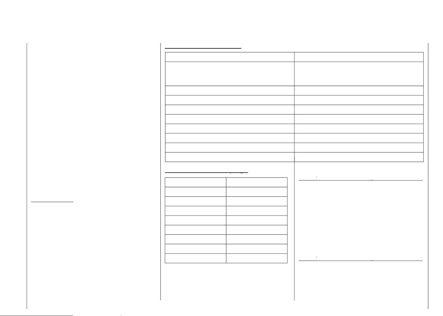
Antenne
Teleskopantenne, zehngliedrig, ca. 1150 mm lang
Abmessungen ca.
Umhängeriemen, 20mm breit
Umhängeriemen, 30mm breit
Lehrer/Schüler Kabel für mx-12
Für die Kombination von Graupner
Handsendern mit DSC-Buchse
Lehrer/Schüler Kabel für mx-12
Für die Kombination von Graupner
mc-... Sendern mit Lehrerbuchse
Teleskopantenne für Sender mx-12
Ansteckbare Servos
Temperaturbereich ca.
Antennenlänge ca.
Abmessungen ca.
Page 8

Laden des Senderakkus
Die wiederaufladbare Senderbatterie kann über die
seitlich am Sender angebrachte Ladebuchse geladen werden.
Der Sender muss während des ganzen Ladevorgangs
auf „OFF“ (AUS) geschaltet sein. Niemals den Sender
einschalten, solange er mit dem Ladegerät verbunden ist! Eine auch nur kurzzeitige Unterbrechung des
Ladevorgangs kann die Ladespannung derart ansteigen
lassen, dass der Sender durch Überspannung sofort
beschädigt oder ein erneuter Ladestart ausgelöst und
der Akku u. U. total überladen wird.
Achten Sie deshalb auch immer auf einen sicheren
und guten Kontakt aller Steckverbindungen. Eine,
wenn auch nur kurze Unterbrechung aufgrund eines
Wackelkontakts führt unweigerlich zu Fehlfunktionen am Ladegerät.
Polarität der mx-12 Ladebuchse
Die auf dem Markt befindlichen Ladekabel anderer Hersteller weisen oft abweichende Polaritäten auf. Verwenden Sie deshalb nur original GRAUPNER-Ladekabel.
Ladestrom
Um Schäden am Sender zu verhindern, darf der Ladestrom ohne Ladekreissicherung max. 500 mA (0,5 A)
und mit Ladekreissicherung max. 1,5 A betragen.
• Vergewissern Sie sich durch einige Probeladungen
von der einwandfreien Funktion der Abschaltauto matik bei Automatik-Ladegeräten.
Dies gilt insbesondere, wenn Sie den serienmäßig
eingebauten NiMH-Akku mit einem Automatik-Lade gerät für NiCd-Akkus aufladen wollen.
Passen Sie ggf. die Delta-Peak Abschaltspannung
an, sofern das verwendete Ladegerät diese Option
erlaubt.
• Der Ladestrom muss mit der manuellen Ladestrom wahl des Ladegerätes eingestellt werden, um sicher
zu stellen, dass der max. Ladestrom niemals 1,5 A
übersteigen kann!
Niemals dem Ladegerät die automatische Lade stromwahl überlassen!
• Führen Sie keine Akku-Entladungen oder Akku pflegeprogramme über die Ladebuchse durch!
Die Ladebuchse ist für diese Verwendung nicht
geeignet!
• Soll der Senderakku mit mehr als 1,5 A geladen
werden, muss dieser unbedingt aus dem Sender inneren entnommen werden, um mögliche Schä den durch Überhitzung im Sender zu vermeiden.
Standard-Ladegeräte
Best.-Nr.
6422 Minilader 2
Best.-Nr. 6427 Multilader 3
Best.-Nr. 6426 Multilader 6E*
Best.-Nr. 6428 Turbomat 6 Plus*
Best.-Nr. 6429 Turbomat 7 Plus*
Best.-Nr.
6412 Ultramat 12*, **
Best.-Nr. 6417 Ultramat 25*, **
Best.-Nr. 6416 Ultra Duo Plus 30*, **
* Für die Aufladung ist zusätzlich für den Sender das Ladekabel Best.-Nr. 3022, für
Empfängerakku Best.-Nr. 3021 erforderlich.
** 12-V-Ladestromquelle erforderlich
Hinweise zur Aufladung des Senderakkus mit einem
Automatik-Ladegerät
• Es sind stets die Ladeanweisungen des Ladegeräte
sowie des Akkuherstellers einzuhalten.
Automatik-Ladegeräte mit speziellen NiMH-Ladeprogrammen
Best.-Nr. 6419 Ultramat 5*, **
Best.-Nr. 6410 Ultramat 10*
Page 9
9
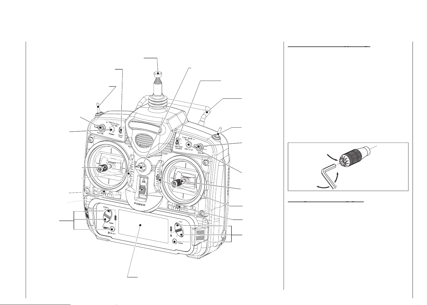
Antenne
Autorotations-Schalter (für Heli)
Trainer Schalter
Trimmung
Trimmung
Trimmung
Trimmung
für Tragegriff
Trimm-Schalter
wieder fest.
An der Oberseite des mx-12-Senders finden Sie eine
Page 10
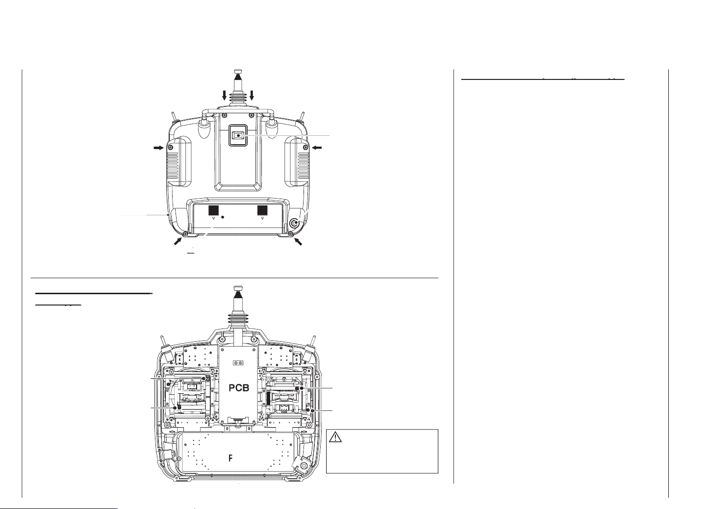
Trainerbetrieb
Akku sowie 6 Schrauben an der Unterseite des
werden. Jede Schraube auf gewünschte Spannung ein-
für schwächeren Druck).
Achten Sie beim Einstellen der Rasterspannung darauf,
vorgangs die PC-Grundplatine berührt.
führung. Wenn Ihnen diese Einstellung nicht zusagt,
abziehen, dazu die Laschen nach innen drücken.
und abnehmen, Batterie entnehmen.
drehen, ebenso die beiden Schrauben des
Antennensockels.
trennen, ausgehend von der Unterseite.
Kabelstecker abziehen.
ein schwarzer Kunststoffhebel mit Feder zur Knüp-
pelrückstellung - im Zweifelsfall durch Bewegen des
Knüppels lokalisieren und die Feder mit der Zange
aushängen.
Vorsicht
Page 11
wegen) und von seinem Lager abheben.
rechten Knüppeleinheit einbauen (das Lager befindet
sich dann oben an der rechten Knüppeleinheit).
sich ein Metallstreifen, der die Rasterfunktion be-
wirkt. Dieser ist mit 2 Schrauben fixiert. Schrauben
lösen und Metallstreifen an linker Knüppeleinheit
anbringen.
Vor dem Zusammenbauen (in umgekehrter Rei-
henfolge) die Gängigkeit der Knüppel prüfen.
Beide mehrpoligen Kabelstecker wieder einstecken.
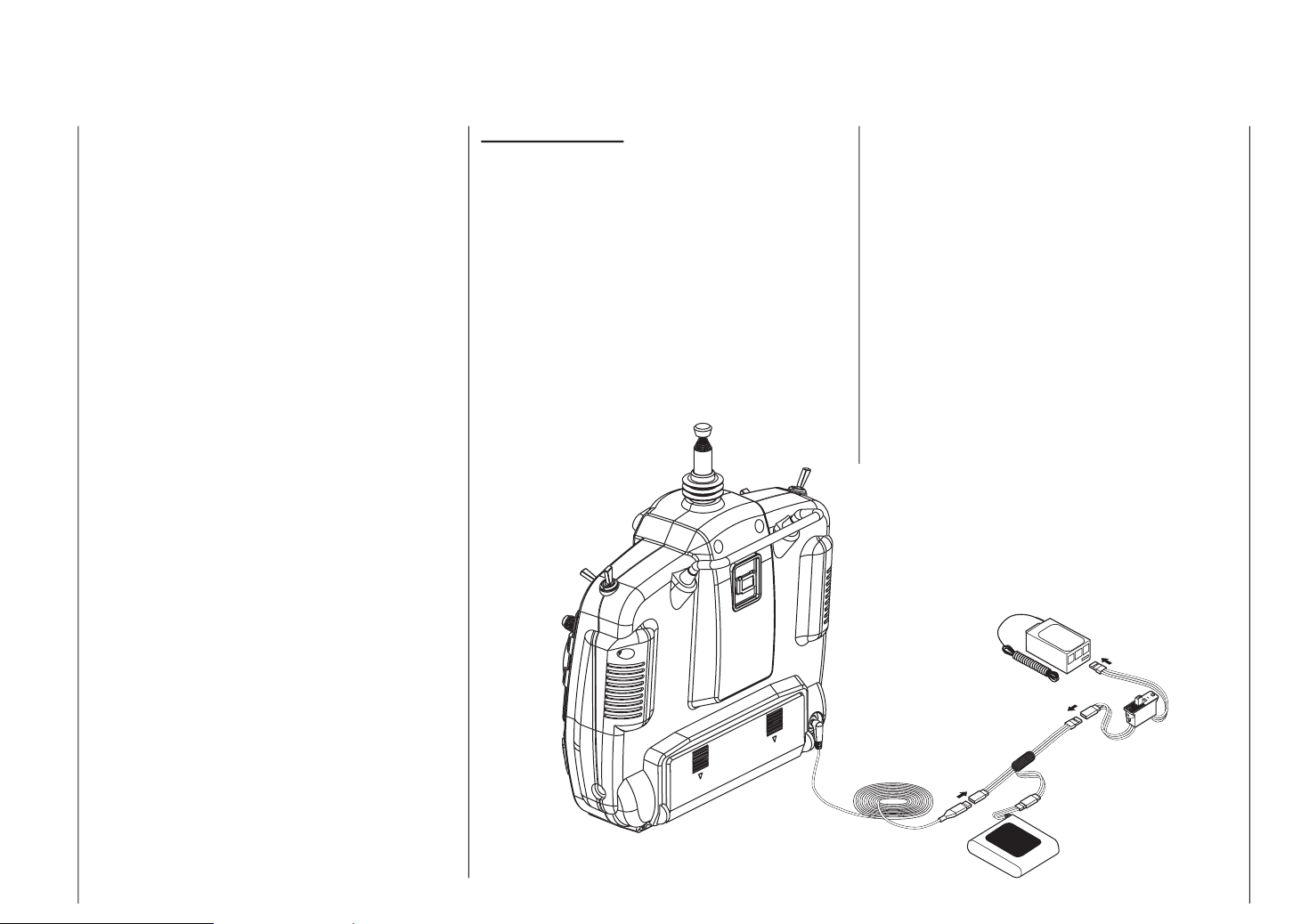
AUS; in dieser Stellung erfolgt keine HF-Abstrahlung
vom Sendermodul.
der Rückseite des Senders ein.
Display leuchtet.
V-Kabel in das Schalterkabel und stellen Sie den
Schalter auf EIN.
Achten Sie darauf, dass Schalterkabel, V-Ka-
bel und DSC-Kabel fest verbunden sind.
mente überprüfen, ohne das Sender-Akkupack
mit den vollen 200mAh Betriebsleistung des Senders
zu belasten. Über die DSC-Funktion verbrauchen
Sie dagegen nur etwa 70mAh, da das Sendermodul
nicht aktiv ist.
am Modell vornehmen, ohne Fernsteuersignale
abzustrahlen. Damit können Sie Ihr Modell auch
dann startfertig machen, wenn ein anderer Pilot auf
Ihrer Frequenz fliegt, ohne sein Modell zu stören.
Mit dieser Funktion sollten Sie Ihr Modell nur
prüfen, wenn es auf einen Montageständer
gesetzt ist!
V-Kabel
AKKU
Page 12
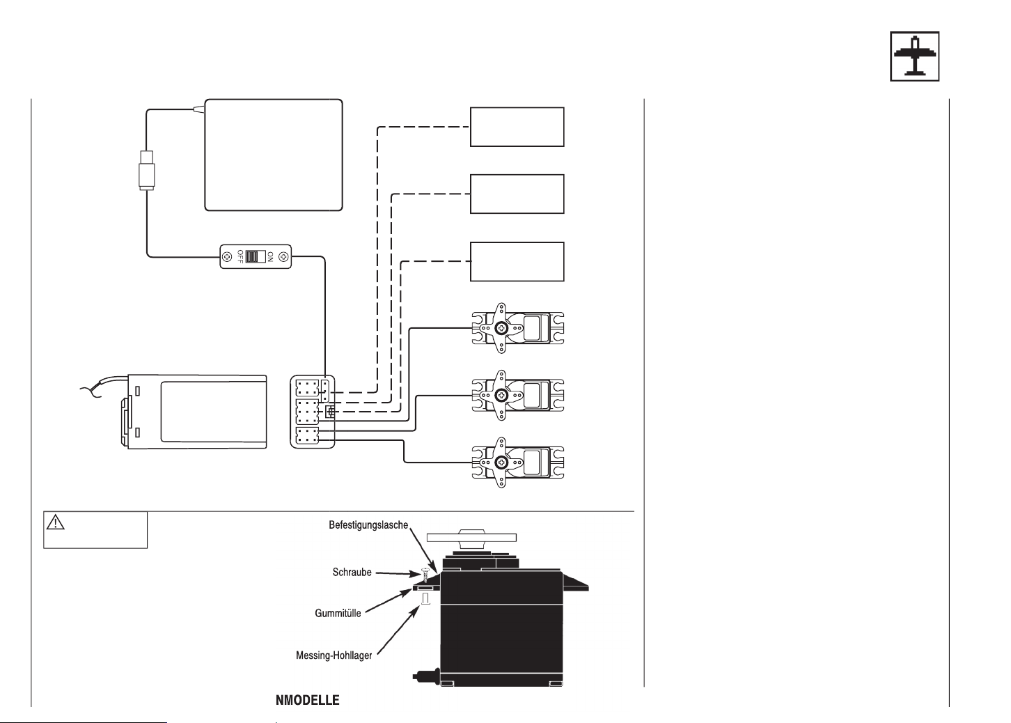
AKKU
THRO
ANTENNE
Voraussetzungen für die Installation
mindestens 6mm Dicke. Fixieren Sie den Schaum
gummi mit Gummibändern am Empfänger, um ihn
bei einem Crash oder einer harten Landung zu
schützen.
Messing-Hohllagern, um sie vor Vibration zu schüt-
zen. Ziehen Sie die Befestigungsschrauben nicht
zu fest an, sonst wird der Vibrationsschutz durch die
Gummitüllen hinfällig. Im Bild links unten sehen Sie,
wie ein Servo richtig montiert wird. Die Messinglager
werden von unten in die Gummitüllen eingeschoben.
Wenn die Servo-Befestigungsschrauben richtig an-
gezogen sind, bieten sie Sicherheit sowie einen
Vibrationsschutz für Ihr Servo.
reich frei beweglich sein. Achten Sie darauf, daß
keine Gestängeteile den freien Servoausschlag
behindern können.
oder Vibrationen eingebaut sein. Der Schalterknopf
muß über seinen gesamten Arbeitsbereich frei zu-
gänglich sein.
eingebaut sein, damit sie sich nicht um Propeller
oder Steuerflächen wickeln kann.
Antenne nicht kürzen!
Page 13
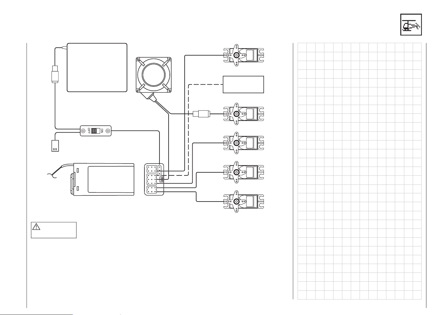
AKKU
Antenne nicht kürzen!
ANTENNE
AUX1
AILE
THRO
LADEBUCHSE
13
Page 14
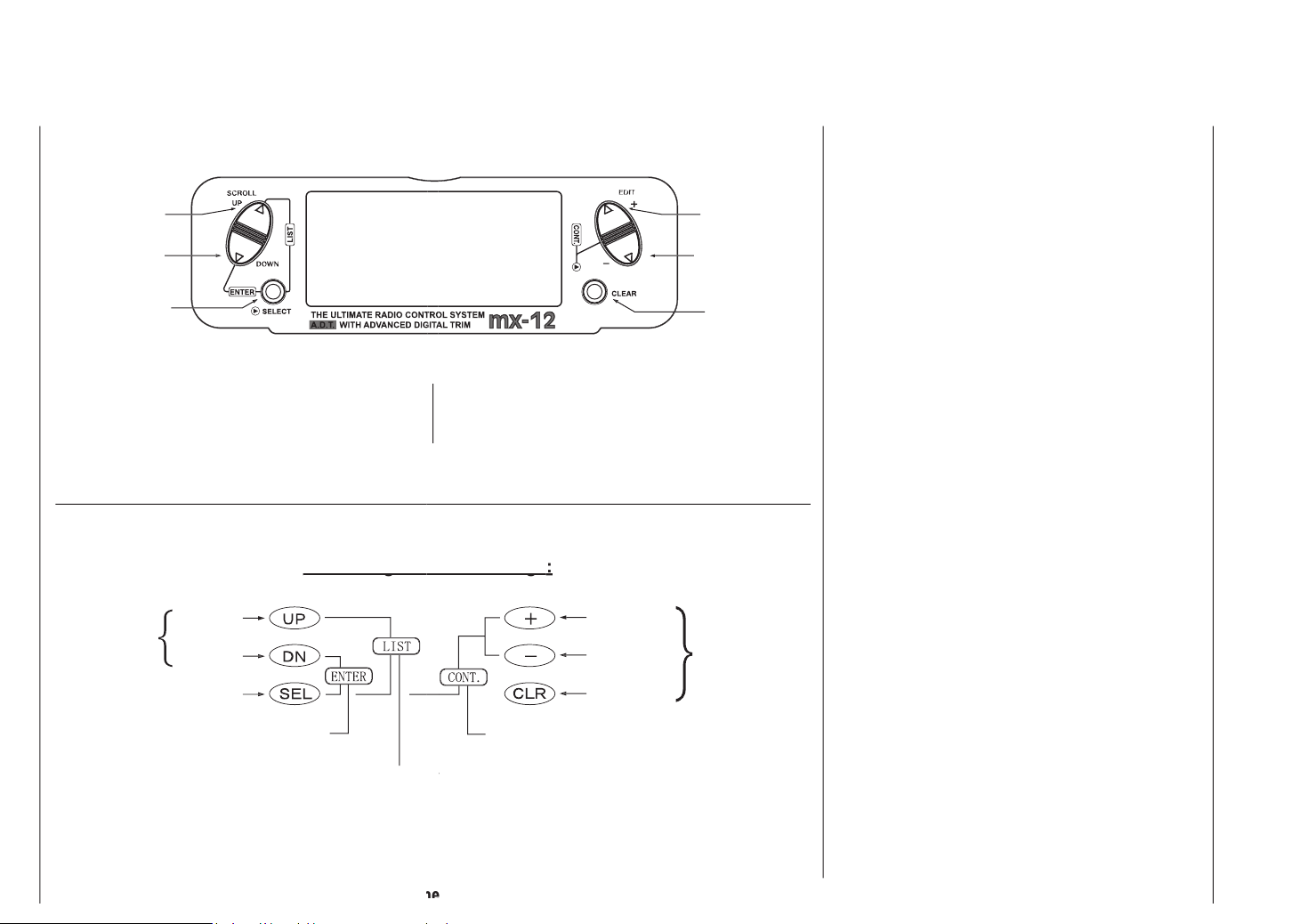
Auswahltaste
wählen Sie die gewünschte Funktion an.
.
Tasten
für Änderungen
ten Funktionen.
Tasteneingaben und Anzeige
Tasteneingaben und Anzeige
Tasteneingaben und Anzeige
AUF-Taste
AB-Taste
Taste
Verringern-Taste
Akkuwarnung und Anzeige
Warnung ertönt.
Alle vorprogrammierten Daten werden durch eine
Jahre lang haltbar. Sollte die Lithium-Batterie nachlas-
wenden Sie sich dazu an Ihren Händler oder an eine
Vorgehen ernster Datenverlust oder Schaden eintreten
Page 15
Anzeigekontrast der mx-12 einstellen, um in jedem
Wetter und bei jeder Temperatur die optimale Ablesbar-
Trimmstellung graphisch angezeigt.
werden können, etwa beim Transport.
Wenn Sie ein neues Modell auswählen bzw. den Spei-
triebszeit auf den Wert „0:00:00“ zurückgesetzt.
Page 16
Anwahl des Funktionsmodus
len.
drücken.
das Menü scrollen und die gewünschte Funktion
anwählen.
Klappen)
AIL
Seitenruder)
ttle
ferenzierung, nur in Wing Type)
X
ttle
X
Page 17
Anwahl des Systemmodus
len.
das Menü scrollen und die gewünschte Funktion
anwählen.
WING TYPE
)
(TS)
Page 18
Page 19
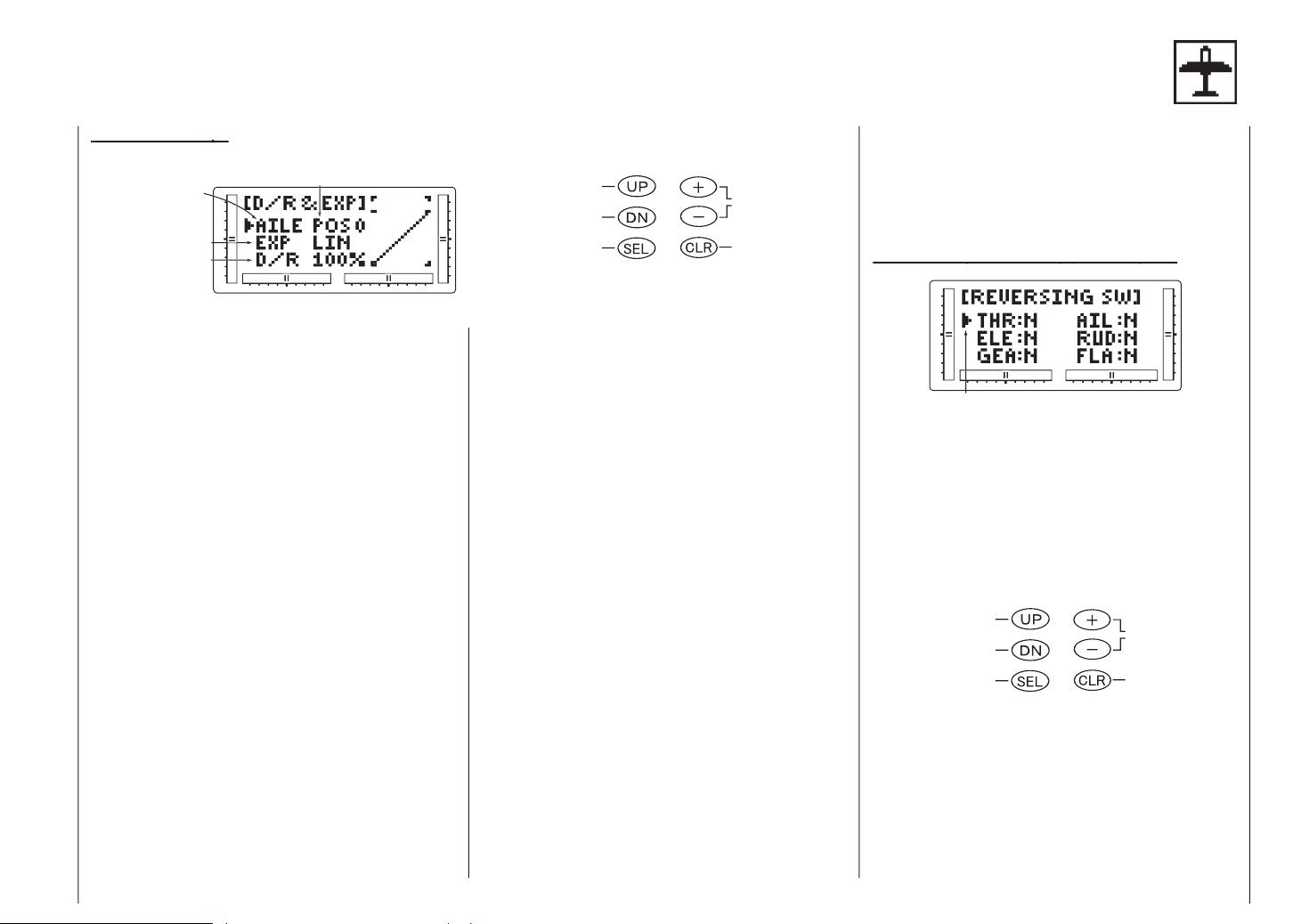
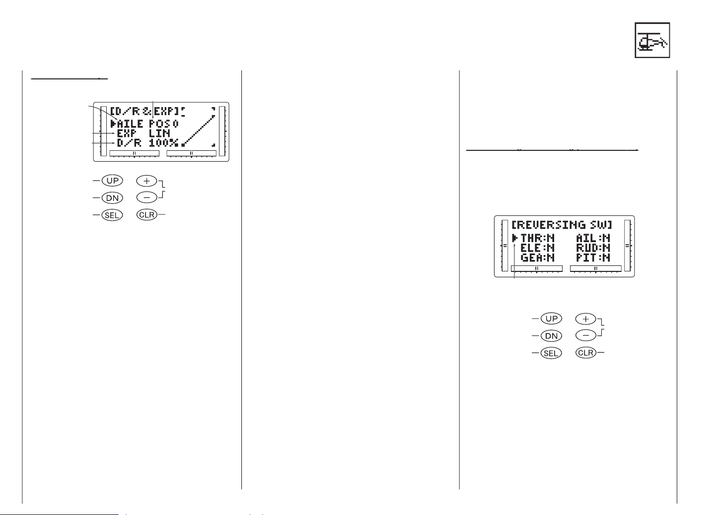
AILE: Querruder
Wert
Ausschlag, desto empfindlicher spricht die Steuerung
Ausschläge am Rand des Knüppelbereichs. Am End-
weniger Servobewegung erfolgt bei Steuerbewegungen
es Drücken von DOWN und SELECT an.
„
(Quer- , Seiten- oder Höhenruder) erscheint.
Wert einstellen wollen. Die Zahl rechts über dem
aktuellen Wert zeigt die aktuelle Stellung des Dual
Rate - Schalters für den gewählten Kanal. Sie sehen
eine 0 oder eine 1, je nach Schalterstellung. Um die
entgegengesetzte Schalterstellung zu wählen, legen
Sie den entsprechenden Dual Rate - Schalter in die
andere Stellung um. Die Zahl über dem aktuellen
Dual Rate - Wert zeigt die Änderung an.
gehörenden Wert ein. Bringen Sie den Cursor mit
der SELECT-Taste auf die Position D/R und drücken
Sie die (-)-Taste, um den Servoausschlag zu verrin-
gern, zum Erhöhen drücken Sie auf (+). Wie schon
oben erwähnt, ist der Wert von 0-125% pro Schal-
terstellung und Kanal einstellbar.
)
ins Bild
SELECT-Tasten verlassen Sie den
EXPO-Modus.
AIL 2: QUERRUDER
ELE 3: HÖHENRUDER
RUD 4: SEITENRUDER
GEA 5: FAHRWERK
FLA 6: KLAPPEN
Weg den Ausschlag eines Servos (Kanals) um. Diese
was das Einrichten der Servos beim Einbau in das
es Drücken von DOWN und SELECT an.
Display
mit Hilfe der Steuerknüppel, Schalter und Potentio-
Page 20
meter.
Notieren Sie dabei die Ausschlagrichtung jeder
Steuerfläche.
schlag-Umkehrfunktion haben wollen, und wählen
diesen mit der SELECT-Taste an.
schlagrichtung des Servos ändern. CLEAR stellt die
Einstellung auf „Normal“ zurück.
schlagrichtung durch Betätigen der entsprechenden
Steuerungs-Geber überprüfen.
- Funktion erreichen Sie durch
Drücken der DOWN-Taste.
- Funktion erreichen Sie durch Drü-
cken der UP-Taste.
Funktion
durch gleichzeitiges Drücken von UP und SELECT
verlassen.
Trim Funktion hilft Ihnen, den Servoarm präzise auf
Verdrehen in die gewünschte Position bringen läßt.
Wert Ändern
Auswahl auf 0
SELECT in den Funktionsmodus wechseln.
scheint.
Servo-Mitte nach Wunsch einstellen.
ACHTUNG
Setzen Sie die Funktion
nur
zur Feinjustierung ein, sonst besteht die
Gefahr, daß der maximale zulässige Wert
überschritten wird. Sub Trim ist nur eine
Hilfsfunktion. Sie dient nicht dazu, sau-
bere mechanische Feinarbeit an Servo
und Gestänge zu ersetzen.
(Servo Reverse) gelangen Sie
durch Drücken der DOWN-Taste.
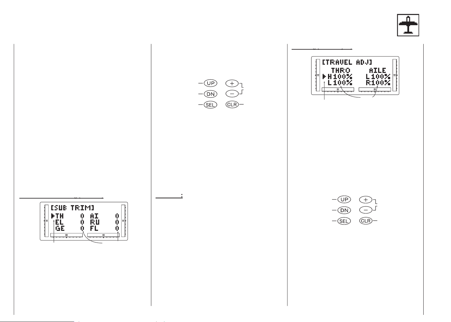
THRO 1: GAS
AIL 2: QUERRUDER
THRO 1: GAS
AIL 2: QUERRUDER
Travel Adjust dient dazu, den Ausschlag einer Steuer-
fläche nach jeder Steuerrichtung präzise festzulegen.
vom Neutralpunkt (Mitte); er kann unabhängig für jede
Ausschlagrichtung eingestellt werden. Die Werkseinstel-
trimmung
Anzupassenden
Wert ändern
Wert auf 100% (Nor-
SELECT in den Funktionsmodus wechseln.
ADJ
kiert ist.
Schalter, etc.) aus der Mittelstellung in die Richtung,
durch erneutes Drücken der DOWN-Taste.
durch gleich-
zeitiges Drücken von DOWN und SELECT verlas-
sen.
Page 21
die Sie einstellen wollen. Ein Pfeil links vom Travel
Adjust - Wert zeigt die derzeit eingestellte Richtung
an.
in die zu bearbeitende Richtung und drücken Sie
auf (+) or (-), bis der richtige Betrag für den Servo-
ausschlag auf dem Display angezeigt ist. Mit (+)
erhöhen Sie den Betrag, mit (-) verringern Sie ihn.
Kanäle.
(Servo-Mitteneinstellung).
SELECT verlassen Sie die Funktion
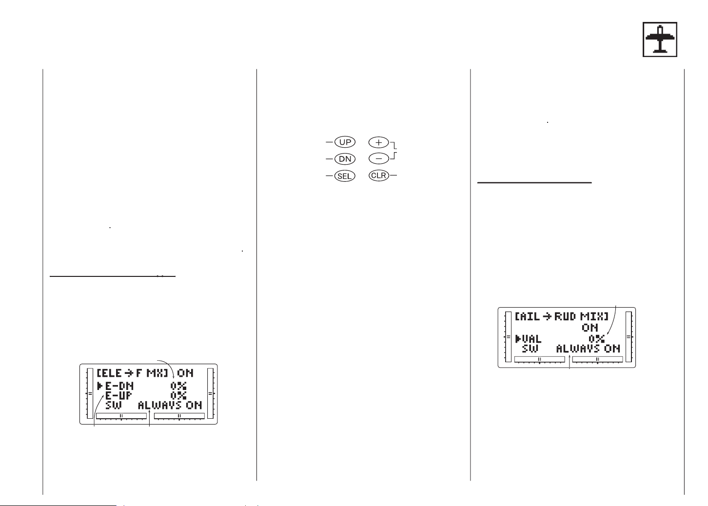
Wenn dieses System aktiviert und ein Wert für die
Abstellen des Mixers zuweisen.
Wahl des Mischerschalters
ALWAYS ON: Immer AN
AN
AILE D/R: AILE D/R-Schalter auf Position 1
Travel Adjust
Auswahl ändern
Wert ändern/Schalter
wählen
Auswahl zurückset-
AN)
ges Drücken von DOWN und SELECT an.
in der die Klappen zugemischt werden sollen.
In der Stellungsanzeige ist nun der UP- oder
der DOWN-Richtungspfeil markiert.
gen Wert für die Klappenstellung festlegen. Wenn
Sie den Klappenausschlag umkehren wollen, drü-
cken Sie auf CLEAR, wodurch der Mischwert auf
den Grundwert (0%) gesetzt wird, und erhöhen oder
verringern Sie den Wert mit derjenigen der (+) oder
(-) Tasten, die der ursprünglich benützten Taste
entgegengesetzt ist.
festgelegt haben, drücken Sie den Höhenruderge-
ber in die andere Richtung und wiederholen die in
(5) oben genannten Schritte für den 2. Höhenruder-
Mischwert.
lung der Schalterstellung. Wählen Sie mit den (+)
oder (-) -Tasten einen der sechs Schalter oder
„Immer AN“ aus.
AIL
zeitiges Drücken von DOWN und den Kanaltasten
verlassen.
wird, kann nach dem untenstehenden Schema gewählt
werden. Der Grundwert (Werkseinstellung) ist 0%.
Wahl des Mixerschalters Schalteranzeige:
ALWAYS ON: Mixer immer AN
AN
AILE D/R: AILE D/R Schalter Position 1
AN
Page 22
Auswahl ändern
Wert ändern/Schalter
wählen
Auswahl zurücksetzen
SELECT in den Funktionsmodus wechseln. Die UP-
oder DOWN-Taste drücken, bis
oberen Teil des Displays erscheint.
Sie den Seitenruderausschlag, der dem Querruder
zugemischt werden soll. Zur Umkehrung der Misch-
richtung drücken Sie auf CLEAR. Dadurch bringen
Sie den Mischwert auf die Werkseinstellung (0%),
und erhöhen oder verringern den Wert mit derjeni-
gen der (+) oder (-) - Tasten, die der ursprünglich
benützten Taste entgegengesetzt ist.
Funktion Schalterzuweisung.
ter oder die Funktion, mit der der Quer- auf Seitenru-
dermixer aktiviert werden soll.
Funktion.
verlassen,
indem Sie gleichzeitig auf DOWN und SELECT
Wert ändern
SELECT in den Funktionsmodus wechseln. Die UP-
oder DOWN-Taste drücken, bis
oberen Teil des Displays erscheint.
Tasten (+) und (-).
Durch Drücken der CLEAR-Taste wird die
Leerlauf-Funktion beendet und bis zur Reakti-
vierung gesperrt.
Mischerfunktion
AIL > RUD MIX.
Sie gleichzeitig auf DOWN und SELECT drücken.
y
y
Ausschlag (DN 200~0~UP 200)
Wert ändern
Auswahl auf Anfangs-
tion
Auswahl ändern
SELECT in den Funktionsmodus wechseln.
TEM im oberen Teil des Displays erscheint
stellenden Kanäle an.
ten Stellungen der Klappen fest.
Page 23
Funktion
verlassen,
indem Sie DOWN und SELECT gleichzeitig drücken.
Wenn Sie die Funktionen differenzierte Querruder,
vorhanden sein (1 pro Ruderfläche). Wählen Sie im
Aileron Mixing zu gelangen.
Achtung:
im Funktionsmodus nur angezeigt, wenn
vorher im Systemmodus entweder Flaperon
oder Delta Wing gewählt wurde.
Wert der Differenzierung
für den Master-Kanal auch die des Slave-Kanals verän-
Jeder Kanal dieser Fernsteuerung wird mit einer Kurz-
drückt und schalten den Sender ein, sodass Sie in
den Systemmodus gelangen. (siehe Seite 41)
Menü
an. (siehe Seite 41)
anwählen und mit den +/- -Tasten z.B. FLAPERON
auf ON umschalten (2 Querruder)
(Querruder rechts = Empfängerausgang 2)
(Querruder links = Empfängerausgang 6)
zweimal die DOWN- und SELECT-Taste gleichzeitig
drücken.
Menü
an, um die
gewünschte Einstellung für die Querruder-Differen-
zierung mit den +/- - Tasten vorzunehmen.
(0% = NORM bis 100% = SPLIT)
gleichzeitig, kehren Sie zur Grundanzeige zurück.
verbinden
Page 24

SELECT in den Funktionsmodus wechseln.
oberen Teil des Displays erscheint.
Master- und Slave-Kanal auswählen:
tion zu bringen.
weiterhin die aktuellen Mixerkanäle oben im Display
an, aber jetzt weist ein Pfeil auf die gerade einzustel-
lende Knüppelposition (Master).
Mischwerte festlegen:
Misch-Richtung und erhöhen oder verringern Sie
mit (+) oder (-) den Mischwert für den Slave-Kanal.
Der jetzt im Display angezeigte Wert ist der gewähl
te aktuelle Mischwert. Drücken Sie dann den Knüp-
pel auf die andere Seite, um den Mischwert für diese
Richtung einzustellen.
Aktivierung des Mischerschalters einstellen:
Anzeige mit “ALWAYS ON“ zeigt, daß der Schalter,
dem der Mischer gerade zugeordnet ist, immer aktiv
(ON) sein soll.
Mischer-Bedienung und Schalter:
Jedes Mischerprogramm kann mit einem Hebel oder
werden können, sind rechts aufgeführt; ihre Abkürzun-
play zeigt die aktuellen Mischerkanäle oben im
Display an, in der Mitte steht dabei das Wort „OFF-
SET“. Der Wert auf der rechten Seite ist der Neutral-
punkt für den Mischer-Offset, hier 0.
wählt werden. Dieser Wert ist der neue Neutralpunkt
für den Slave-Kanal. (Er zeigt an, daß der Mischer
aktiviert ist). Durch Drücken auf CLEAR setzen Sie
den Wert auf 0 zurück.
um die Funktion Programmierbare Mischer zu ver
lassen. Nach einiger Übungszeit werden Sie die
programmierbaren Mischer besser verstehen. Die
Mischmöglichkeiten sind praktisch grenzenlos.
Die Funktion Fail Safe/Halten ist nur verfügbar, wenn Sie
den mx-12 Sender in der PCM-Modulationsart betrei-
ben
verlust am Empfänger der Schaden an Ihrem Modell
Wie schon oben gesagt, ist die Fail-Safe/Hold - Funktion
tung und mit dem Wert, der im Mixer vorgegeben ist.
Jeder programmierbare Mischer hat einen “Offset“. Der
Auswahl Mixerschalter
ALWAYS ON: Mixer immer AN
AN
AN
AN
AILE D/R: AILE D/R-Schalter Pos. 1
AN
Auswahl auf Normal
Page 25

Anzeige der Fail Safe Seite
TH Gas RU Seitenruder
AI Querruder GE Fahrwerk
Anzeige des Hold-Setup
weg
Wechseln von Servo
Auswahl (F.S.
SELECT in den Funktionsmodus wechseln. Die UP-
oder DOWN-Taste drücken, bis FAIL SAFE im obe-
ren Teil des Displays erscheint.
der SELECT- Taste.
Halten und Servoposition Einstellen.
den, drücken Sie den entsprechenden Knüppel
in die Stellung, die das Servo beim Eintreten des
Fail Safe - Falles halten soll. Durch Drücken von
CLEAR speichert der Sender alle Knüppelstellungen
ab.
tionen durch.
Funktion
durchgleichzei-
tiges Drücken von DOWN und SELECT verlassen.
SELECT in den Funktionsmodus wechseln.
Die UP- oder DOWN-Taste drücken, bis
TRAVEL
im oberen Teil des Displays erscheint.
entsprechen folgendem Schema:
Anzeige 1: Gas
Anzeige 2: Querruder
Anzeige 3: Höhenruder
Anzeige 4: Seitenruder
Anzeige 5: Fahrwerk
Anzeige 6: Klappen
Anzeige.
-
Anzeige verlassen, indem Sie gleichzeitig DOWN
und SELECT drücken.
Page 26
AILE: Roll
Anzeige
Auswahl auf Anfangs-
wert setzen
Ausschlagweg einer Funktion über einen Schalter zu
verändern. Da der Ausschlag entlang des Wegs variiert,
volle Ausschläge am Rand des Knüppelbereichs. Am
verändert. Diese Veränderbarkeit läßt sich von 0-100%.
weg, 100% ist der volle Expowert. Je höher der
tion:
ges Drücken von DOWN und SELECT an.
oben links im Display erscheint.
(Roll, Heck oder Nick) erscheint.
Wert einstellen wollen. Die Zahl rechts über dem
aktuellen Wert zeigt die aktuelle Stellung des Dual
Rate - Schalters für den gewählten Kanal. Sie sehen
eine 0 oder eine 1, je nach Schalterstellung. Um die
entgegengesetzte Schalterstellung zu wählen, legen
Sie den entsprechenden Dual Rate - Schalter in die
andere Stellung um. Die Zahl über dem aktuellen
Dual Rate - Wert zeigt die Änderung an.
gehörenden Wert ein. Bringen Sie den Cursor mit
der SELECT-Taste auf die Position D/R und drücken
Sie die (-)-Taste, um den Servoausschlag zu verrin-
gern, zum Erhöhen drücken Sie auf (+). Wie schon
oben gesagt, ist der Wert von 0-125% pro Schalter-
stellung und Kanal einstellbar.
)
zum Bild
SELECT verlassen Sie den
EXPO-Modus.
Wege die Richtung eines Servos (Kanals) um. Diese
was das Einrichten der Servos beim Einbau in das
ges Drücken von DOWN und SELECT an.
Display
rung mit Hilfe der Steuerknüppel, Schalter und
Potentiometer. Notieren Sie dabei die Ausschlagrich-
tung jeder Funktion.
THR 1: Gas
AIL 2: Roll
Trim
wählen
Ausschlagrichtung auf
Page 27

schlag-Umkehrfunktion haben wollen,und wählen
Sie diesen mit der SELECT-Taste an.
schlagrichtung des Servos ändern. CLEAR stellt die
Einstellung auf „Normal“ zurück.
schlagrichtung durch Betätigen der entsprechenden
Steuerungs-Geber überprüfen.
- Funktion erreichen Sie durch
Drücken der DOWN-Taste.
- Funktion erreichen Sie durch Drü-
cken der UP-Taste.
Funktion
durch gleichzeitiges Drücken von UP und SELECT
verlassen.
(Sub Trim)
(Sub Trim)
Alle 6 Kanäle lassen sich in einem Bereich von +/-
Verdrehen in die gewünschte Position bringen läßt...
TH 1: Gas
AI 2: Roll oder Roll/Pitch
Wert der Feintrim-
weg-Einstellung
Wert ändern
Auswahl auf Normal
SELECT in den Funktionsmodus wechseln.
scheint.
Servo-Mitte nach Wunsch einstellen.
ACHTUNG
zur Feinjustierung ein, sonst besteht die
Gefahr, daß der maximal zulässige Wert
überschritten wird. Sub Trim ist nur eine
Hilfsfunktion.
Sie dient nicht dazu, saubere mechanische
Feinarbeit an Servo und Gestänge zu
ersetzen.
durch Drücken der DOWN-Taste.
durch erneutes Drücken der DOWN-Taste.
durch gleichzeitiges Drücken von DOWN und SE-
LECT verlassen.
werden. Die Werkseinstellung liegt bei 100% in jeder
Ausschlagrichtung.
Ausschlag-Wert
TH 1: Gas
AI 2: Roll oder Roll/Pitch
Wert ändern
Wert auf Normal
SELECT in den Funktionsmodus wechseln.
ADJ
kiert ist.
Schalter, etc.) aus der Mittelstellung in die Richtung,
die Sie einstellen wollen. Ein Pfeil links vom Travel
Adjust - Wert zeigt die derzeit eingestellte Richtung
an.
Page 28
in die zu bearbeitende Richtung und drücken Sie
auf (+) or (-), bis der richtige Wert für den Servoaus-
schlag auf dem Display angezeigt ist. Mit (+) erhö-
hen Sie den Betrag, mit (-) verringern Sie ihn.
Kanäle.
(Servo-Mitteneinstellung).
SELECT verlassen Sie die Funktion
Auswahlfenster im Systemmodus ausgewählt werden.
Wenn kein TS-Typ gewählt ist, wird diese Option
Achtung:
angezeigt, wenn die TS-Typen 2Serv, 3Serv
CCPM in der TS-Typ-Auswahl im System-
modus gewählt sind.
ges Drücken von DOWN und SELECT an.
90° CCPM, 120° CCPM oder 180° CCPM links in
der Mitte auf dem Display erscheint.
Das Auswahlfenster „Wahl des TS-Typs“
erscheint im Systemmodus (Seite 43).
on markiert ist.
einzelnen Mischanteile.
Kanäle aus.
Funktion
Funktion
verlassen,
indem Sie gleichzeitig auf DOWN und SELECT
drücken.
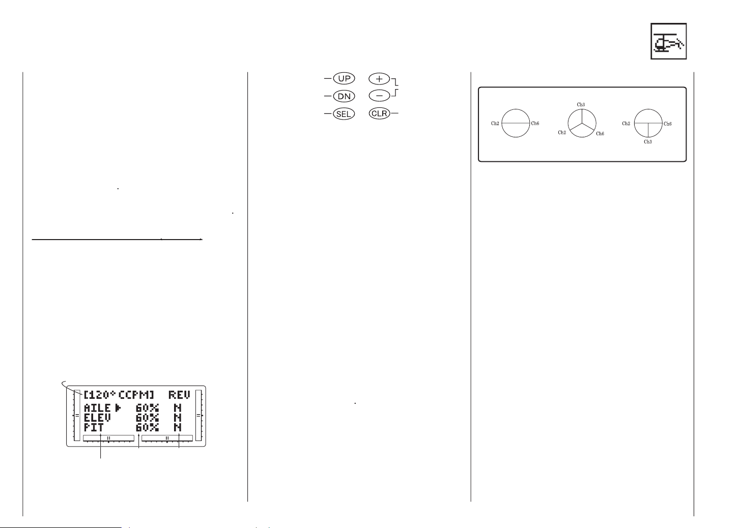
Taumelscheibe des Hubschraubers verbunden sind.
AILE 1: Roll
Wert erhöhen/
verringern oder
Bei diesem Typ wird jeweils 1 Servo zur Steuerung
von Pitch, Rollen und Nicken verwendet.
Wenn dieser Typ im Systemmodus gewählt wurde
(Werkseinstellung), wird die Funktion TS-Mischer
nicht im Display angezeigt.
Die TS wird über 2 Servos axial verschoben, die sich
um 180°gegenüber liegen. Die Nickfunktion wird
mechanisch eingemischt.
Die TS wird über 3 Servos bewegt, die um 120°
versetzt sind. Diese CCPM-Form ist die verbreiteste,
sie ist bei Graupner und bei anderen Herstellern zu
finden.
Die TS wird über 3 Servos bewegt, die um 90°
versetzt sind.
2 Servos (180°)
Ch3 = Nickservo
Ch2 = Vorderes- oder hinteres TS-Servo
Page 29
Ch6 = Linkes TS-Servo
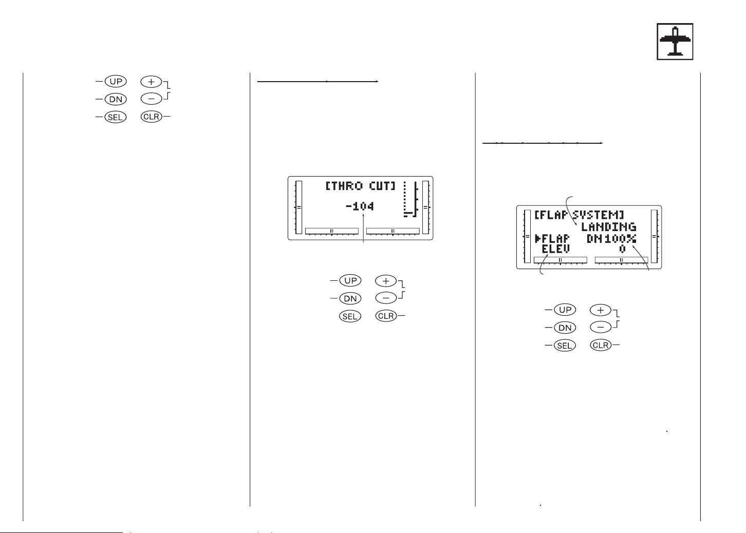
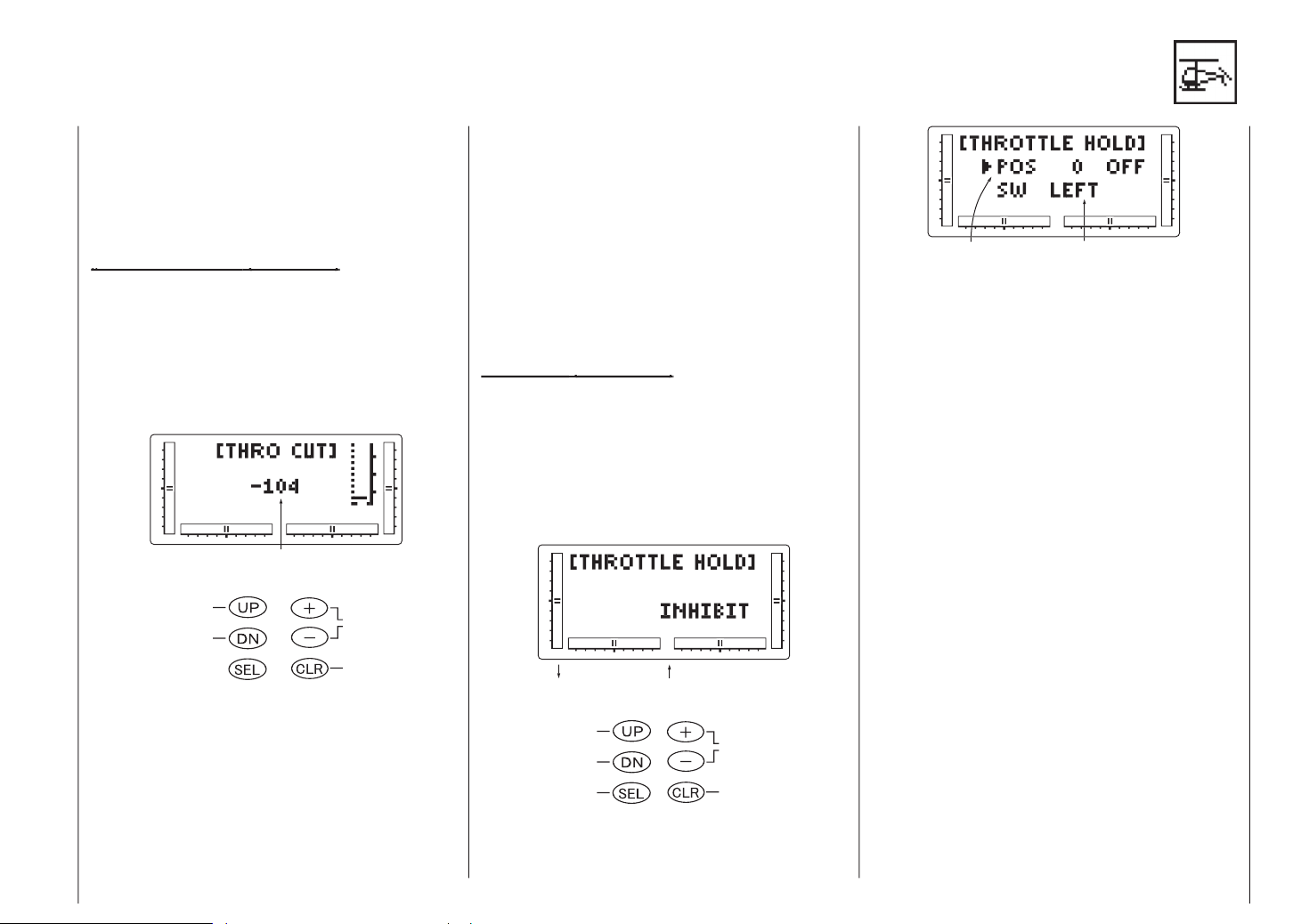
(Throttle Cut)
(Throttle Cut)
vorübergehend auf die unterste Stellung gebracht
wird, solange der Knopf gedrückt ist. Damit läßt sich
weg
Wert ändern
DOWN und SELECT in den Funktionsmodus.
Drücken Sie die UP- oder DOWN-Taste, bis
CUT
im oberen Teil des Displays erscheint.
sition für „Motor AUS“ ein.
Achtung:
AUS-Funktion gesperrt und bis zur Reaktivie-
rung abgestellt.
tion
.
(Autorotation).
(Motor AUS)
durch gleichzeitiges Drücken der DOWN und der
SELECT - Taste verlassen.
Autorotation
( ()
)
Autorotation auf einer definierten Position zu halten.
Taste+/- drücken
Während der Schalterwahl
Wert oder Schalter-
wahl ändern
Autorotation (-20~50)
Autorotations
AN
AILE D/R : AILE D/R-Schalter Position 1
AN
AN
DOWN und SELECT in den Funktionsmodus.
Durch Drücken von (+) oder (-) wird Autorotation
aktiviert und der aktuelle Wert wird angezeigt.
(-) -Tasten so ein, daß die richtige Leerlaufdrehzahl
für Ihren Heli anliegt. Der Einstellbereich geht von
-20% bis + 50%. Sie können den Leerlaufwert,den
Sie für Ihren Motor eingestellt haben, auch für die
Funktion Autorotation verwenden. Soll der Motor bei
Autorotation abgestellt werden, geben Sie einen
negativen oder einen Nullwert ein.
Wenn Autorotation aktiviert ist und der Schal-
ter auf EIN steht, wechselt die Anzeige von
AUS zu EIN. Zusätzlich wird die Gastrim-
mungs-Anzeige verborgen.
CURVE
(Gaskurve).
Page 30
verlas-
sen, indem Sie DOWN und SELECT gleichzeitig
drücken.
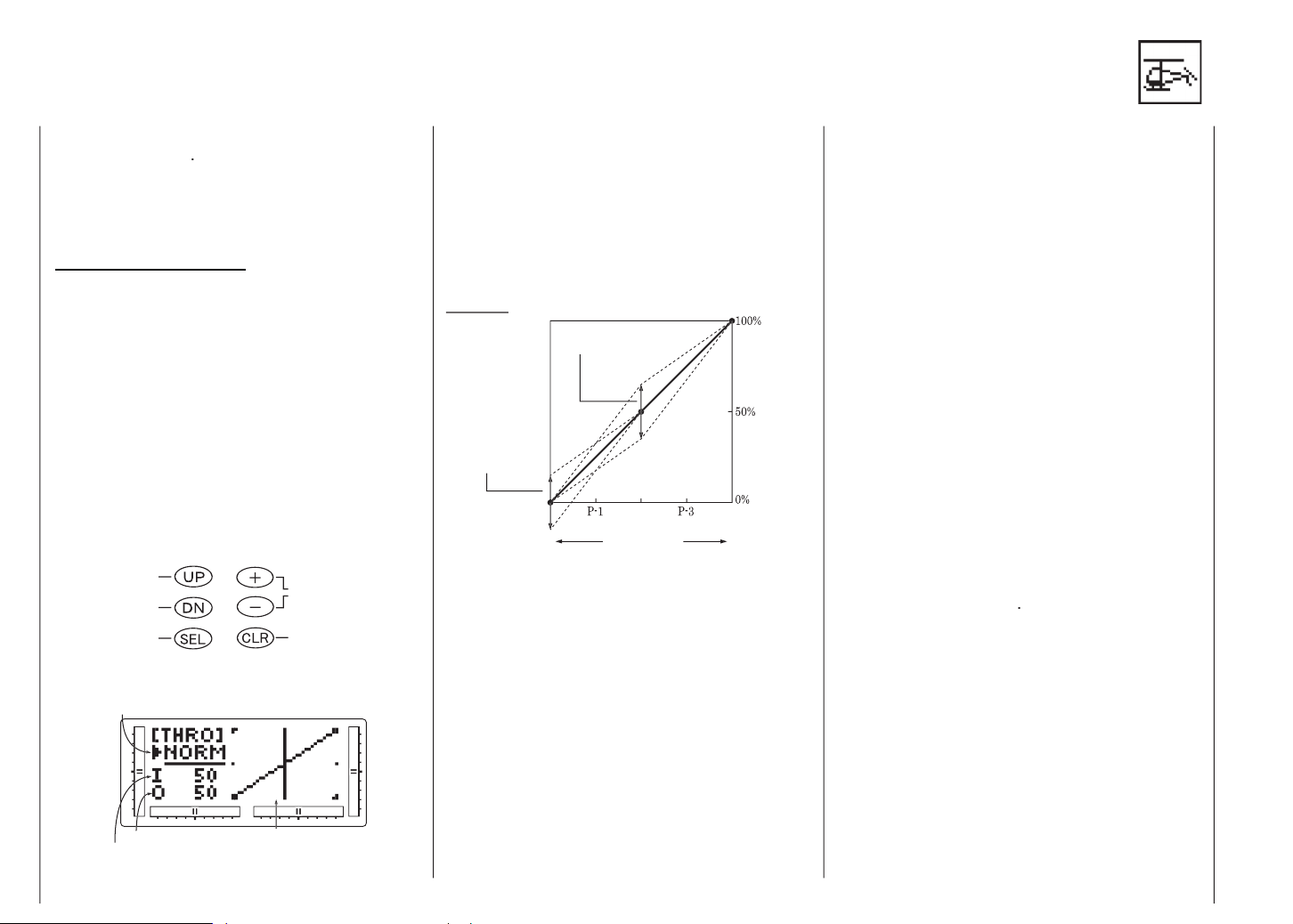
Gaskurven (Throttle Curve)
Der
für die Schwebe-Gaskurve benutzt werden, die Stellung
Jeder der 5 Punkte auf der Gaskurve kann einzeln
von 0-100% eingestellt werden. Diese 5 Punkte ent-
Wert ändern/Schal-
ter wählen
Wert auf 0 setzen
sich im Normal-
wie
Arbeitsbereich für
Arbeitsbereich für
Ausgangswert
ges Drücken von DOWN und SELECT an.
Display
Wählen Sie NORM für Schwebeflug-Kurven
und STUNT für Kunstflug. In diesem Beispiel
werden wir uns speziell mit der Schwebeflug-
kurve befassen.
Drücken der SELECT-Taste aus.
Wert des gewählten Kurvenpunkts. Der Wertebe-
reich für jeden Punkt geht von 0-100% in 0,5%
Achtung:
die Punkte 1 und 3, also bei 25% und 75%,
der Wert „INH“ (versteckt) eingetragen, so-
lange keine anderen Punkte verändert wer-
den
haben, nehmen auch diese Punkte neue
Werte an, bis eine gleichmäßige Kurve
vorliegt. Wenn Sie dies verhindern wollen,
drücken Sie auf SELECT, bis P-1 oder P-3
im rechten oberen Teil des Displays ange-
zeigt wird. Drücken Sie auf (+) oder (-),
um die Punkte 1 (25%) oder 3 (75%) zu
aktivieren. Anschließend können die Werte
einer jeden Kurve durch erneutes Drücken
von (+) oder (-) angepasst werden.
drücken Sie zuerst SELECT, um die Funktion NORM
zu markieren, und dann auf (+) oder (-), um die
Funktion STUNT anzuwählen. Führen Sie die Schrit-
te 4 und 5 so oft aus, bis der Vorgang abgeschlos-
sen ist.
Funktion
Funktion
verlassen, indem Sie gleichzeitig auf DOWN und
SELECT drücken.
Die mx-12 stellt zwei getrennte Gaskurven mit jeweils 5
einstellbaren Punkten zur Verfügung.Damit können zwei
individuelle Abstimmungen von Gas- und Pitchkurve
voreingestellt werden. Wenn die Kurven einmal
eingerichtet sind, können sie im Flug einzeln mit dem
Umschalter für Flugphasen abgerufen werden.
Page 31

Änderungen am Gas-Trimmhebel wirken sich
nicht auf die Eingabewerte für einen der
Punkte auf der Gaskurve aus. Sie bewirken
nur Anpassungen der Stellung für die Leer-
laufdrehzahl.
führt also nicht zu einer Änderung des ursprünglichen
Das Schwebegas hat keinen Einfluß auf die
Flugphasen-Schalterstellung 1.
Arbeitsbereich (Parallel)
Arbeitsbereich
Achtung:
kann nur dann gesetzt werden, wenn dies im
System aktiviert ist.
Wert ändern/Schalter-
und SELECT in den Funktionsmodus.
Wählen Sie NORM für Schwebeflug-Kurven
und STUNT für Kunstflug. In diesem Beispiel
werden wir uns speziell mit der Schwebeflug-
kurve befassen..
Drücken der SELECT-Taste aus.
des gewählten Kurvenpunkts. Der Wertebereich für
jeden Punkt geht von 0-100% in 0,5% - Schritten.
Achtung:
Punkte 1 und 3, also bei 25% und 75%, der
Wert „INH“ (versteckt) eingetragen, solange
keine anderen Punkte verändert werden.
nehmen auch diese Punkte neue Werte an,
bis eine gleichmäßige Kurve vorliegt. Wenn
Sie dies verhindern wollen, drücken Sie auf
SELECT, bis P-1 oder P-3 im rechten oberen
Teil des Displays angezeigt wird. Drücken Sie
auf (+) od. (-), um die Punkte 1 (25%) oder 3
(75%) zu aktivieren. Anschließend können
die Werte einer jeden Kurve durch erneutes
Drücken von (+) od. (-) angepasst werden.
Page 32

drücken Sie zuerst SELECT, um die Funktion NORM
zu markieren, und dann auf (+) od. (-), um die Funk-
tion STUNT anzuwählen. Führen Sie die Schritte 4
und 5 so oft aus, bis der Vorgang abgeschlossen ist.
zustellen, drücken Sie noch einmal auf AUF, bis „H“
angezeigt ist, und wiederholen Sie Schritte 4 und 5.
Funktion
Funktion
verlassen,
indem Sie gleichzeitig auf DOWN und SELECT
drücken.
* Position d. Punktes ist fest
Auto-
ve für Kunstflug sehen Sie weiter unten in Form einer
Page 33

jeweils für Flugphasen Normal und Kunstflug.
Wert ändern/
Auswahl zurück auf
Anfangswert
DOWN und SELECT in den Funktionsmodus.
Auf- oder Abwärtsmischen oder die Flugmodus-
schalter-Stellung. Wenn der Flugmodusschalter und
der Gasknüppel jeweils in der angezeigten Stellung
stehen, ist der Flugmodus unterstrichen.
oder die Flugphasenschalter-Stellung. Wenn der
Flugmodusschalter und der Gasknüppel jeweils in
der angezeigten Stellung stehen, ist die Flugphase
unterstrichen.
der Heckkompensation, mit der (-) -Taste den links-
seitigen Wert. CLEAR setzt den Wert auf 0% zu
rück..
die Flugmodusschalter-Stellungen Normal oder für
Kunstflug (Stunt) einstellen. Die Stellung Stunt
sollten Sie für Vorwärts- und/oder Umkehrkompen-
sation verwenden.
Funktion
verlassen, indem
Sie gleichzeitig auf DOWN und SELECT drücken.
Trimmen Sie den Heckrotor so, dass der Heli nach
flug ein. Der Rumpf des Heli wird sich nun entgegen
tung wie der Hauptrotor drehen. Erhöhen Sie den Wert
von DN (Sinkflug), bis der Heli ohne Drehtendenz sinkt.
für den Master-Kanal auch die des Slave-Kanals verän-
Jeder Kanal dieser Fernsteuerung wird mit einer Kurz-
tung, und mit dem Wert, der im Mixer vorgegeben ist.
Jeder programmierbare Mischer hat einen “Offset“.
Page 34

ALWAYS ON: Mischer immer EIN
AILE D/R: AILE D/R in Position 1
ges Drücken von DOWN und SELECT an.
Display
Die Master- und Slave-Mischer-Kanäle wählen:
Kanal festlegen.
Kanal.
Display werden weiterhin die aktuellen Mischerka-
näle angezeigt, aber jetzt zeigt ein Pfeil auf diejenige
aktuelle Knüppelposition, die angepaßt werden muß.
Einstellen der Mischwerte:
der Sie mischen wollen, drücken Sie dann die (+)
oder (-) -Taste, um den Mischwert für den Slave-Ka-
nal höher oder niedriger anzusetzen. Die Wertanzei-
ge im Display ändert sich und zeigt den jetzt ge-
wählten Mischwert an. Als nächstes drücken Sie den
Masterknüppel in die andere Richtung und stellen
den Mischer dazu passend ein.
Einstellen der Mischerschalter-Aktivierung:
zeige
„Immer EIN“
wählte Schalter immer eingeschaltet ist.
Mischerbetätigung und Schalter:
Jedes Mischerprogramm kann mit einem Schalter oder
Abkürzungen, die im Display auftauchen, und den
Einstellen des Offset für den Mischerkanal:
markiert ist. Dann zeigt das Display oben die
aktuellen Mischerkanäle an, wobei das Wort “OFF-
SET“ in der Mitte der Anzeige steht. Der Wert rechts
ist der Neutralpunkt des Mischeroffset, also momen-
tan 0.
(+) oder (-) gewählt werden. Dies ist dann der neue
Wert für den Neutralpunkt des Slave-Kanals (den
Punkt, an dem der Mischer aktiviert wird). Drücken
Sie auf CLEAR, um den Wert auf 0 zurückzusetzen.
indem Sie gleichzeitig auf DOWN und SELECT
drücken. Mit ein bißchen Übung läßt sich das
TH : Gas RU : Heck
AI : Roll GE : Fahrwerk
Auswahl zurück-
wählen
Mischen leichter verstehen. Seine Einsatzmöglich
keiten werden nur durch Ihre Phantasie begrenzt.
verlust am Empfänger der Schaden an Ihrem Modell
Wie schon oben gesagt, ist die Fail-Safe/Hold - Funktion
Achtung:
aus Sicherheitsgründen auf die Leerlaufstel-
lung festgelegt.
Page 35

Achtung:
Funktionsbezogen.
Vorsicht bei gemischten Taumelscheibenanlenkungen!
ges Drücken von DOWN und SELECT an.
Drücken Sie dann die UP oder DOWN-Taste, bis
oben im Display
tion, die Sie einstellen wollen.
Halten und Servoposition Einstellen.
scheiden, drücken Sie den entsprechenden Knüppel
in die Stellung, die das Servo beim Eintreten des
Fail Safe - Falles halten soll. Durch Drücken von
CLEAR speichert der Sender alle Knüppelstellungen
ab.
tionen durch.
Funktion
Funktion
verlassen,
indem Sie gleichzeitig auf DOWN und SELECT
drücken.
SELECT in den Funktionsmodus wechseln.
Die UP- oder DOWN-Taste drücken, bis
TRAVEL
entsprechen folgendem Schema:
Anzeige 1: Gas
Anzeige 2: Querruder
Anzeige 3: Höhenruder
Anzeige 4: Seitenruder
Anzeige 5: Fahrwerk
Anzeige 6: Pitch
Anzeige.
SAFE
- Anzei-
ge verlassen, indem Sie gleichzeitig auf DOWN und
SELECT drücken.
Page 36

Auswahl (Model Select)
Auswahl (Model Select)
Art einzurichten. Dies ist beim Multi-tasking - Einsatz
wünschenswert.
Typ
Timer umschalten
Timer löschen
drückt und stellen Sie dabei den Ein/Aus-Schalter
auf EIN.
wird jetzt im oberen linken Teil des
Displays angezeigt, andernfalls drücken Sie auf
DOWN oder UP, bis
erscheint.
verfügbaren Modelle an. Dabei wird sein Name im
Display angezeigt.
angezeigt wird,können Sie durch gleichzeitiges
Drücken von DOWN und SELECT die Funktion
Model Select verlassen, damit wird das angezeigte
Modell zum aktiven Modell.
wählen Sie die
Funktion an, und mit CLEAR löschen Sie den Ge-
samtzeitzähler.
Funktion
Funktion
verlassen,
indem Sie gleichzeitig auf DOWN und
drücken.
Typ
und stellen Sie dabei den Ein/Aus-Schalter auf EIN.
NAME
angezeigt wird.
erste Zeichen für den Namen Ihres Modells aus.
das nächste Zeichen zu setzen.
festgelegt sind.
Funktion
Funktion Wahl des Modelltyps -
verlassen,
indem Sie gleichzeitig auf DOWN und
drücken.
Page 37

(Model Type)
(Model Type)
Wahl d. Modelltyps
drückt und stellen Sie dabei den Ein/Aus-Schalter
auf EIN.
Modelltyp ändern.
setzen Sie den Cursor
auf die Position Data Reset.
setzen Sie den Speicher
auf die Werkseinstellung zurück.
Funktion
Funktion
verlassen,
indem Sie gleichzeitig auf DOWN und
drücken.
wenn Sie
ein
Modell mit
Einstellungen
fliegen wollen oder wenn Sie eine alternative Einstellung
und stellen Sie dabei den Ein/Aus-Schalter auf EIN.
linken oberen Teil des Displays angezeigt wird.
aktuelle Modellnummer.
Dies ist wichtig zu wissen, da nur das aktuelle Mo-
dell kopiert werden kann. Drücken Sie auf (+) oder
(-), um den gewünschte Platz (niedrigere Zahl) zu
wählen, auf den das aktuelle Modell kopiert werden
soll.
Modell wird dann auf das gewählte Modell kopiert.
Achtung:
Achten Sie immer darauf, daß das Zielmodell
entweder frei von Einträgen ist, oder ein
Modell ist, das Sie nicht mehr im Senderspei-
cher halten wollen. Wenn der Kopiervorgang
einmal abgeschlossen ist, sind alle Informati-
onen des Zielmodells verloren, und das ak-
tuelle Modell ist mit seinen Daten neu einge-
tragen.
Funktion
Funktion
verlassen,
indem Sie gleichzeitig auf DOWN und
drücken.
Type
Page 38

wahl (Modulation)
wahl (Modulation)
wählen zwischen S-PCM (Pulse Code Modulation) und
Typ
drückt und stellen Sie dabei den Ein/Aus-Schalter
auf EIN, um in den Systemmodus zu kommen.
oben im Display angezeigt wird.
onstyp zu ändern.
drücken, wird die Modulati
ons-Wahl auf die Werksvorgabe S-PCM zurückge-
setzt.
Funktion
verlassen,
indem Sie gleichzeitig auf DOWN und
drücken.
Trainer-Modus
In der Normalanzeige wird die gewählte
Modulationsart oben rechts angezeigt.
teueranordnung (Stick Mode)
teueranordnung (Stick Mode)
ten, die vier Steuerfunktionen Querruder, Höhenruder,
Typ
Auswahl zwischen
Auswahl Steuermo-
drückt und stellen Sie dabei den Ein/Aus-Schalter
auf EIN, um in den Systemmodus zu kommen.
oben im Display angezeigt wird.
dus zu ändern.
drücken, wird die Steueran
ordnung auf die Werkseinstellung (Mode 1) zurück-
gesetzt.
Funktion
verlassen,
indem Sie gleichzeitig auf DOWN und
drücken.
MODUS 1 (Gas rechts)
Tiefenruder
Seitenr. rechts
Motor Vollgas
MODUS 2 (Gas links)
Motor Vollgas
Querr. rechts
Seitenr. rechts
Tiefenruder
Querr. rechts
Seitenr. links
Höhenruder
MODUS 3 (Gas rechts)
Tiefenruder
Querr. links
Höhenruder
MODUS 1 (Gas rechts)
TS-Nick
Heck
TS-Nick
MODUS 3 (Gas rechts)
TS-Nick
TS-Roll
TS-Nick
Querr. links
Motor Leerlauf
Motor Vollgas
Querr. rechts
Seitenr. links
Motor Leerlauf
Motor/Pitch
Heck
TS-Roll
Motor/Pitch Motor/Pitch
Motor/Pitch
TS-Roll
Heck
Motor/Pitch
Seitenr. links
Motor Leerlauf
MODUS 4 (Gas links)
Seitenr. rechts
Motor Vollgas
Querr. links
Motor Leerlauf
MODUS 2 (Gas links)
Motor/Pitch
TS-Roll
Heck
MODUS 4 (Gas links)
Motor/Pitch
Heck
TS-Roll
Motor/Pitch
Querr. rechts
Heck
TS-Roll
Querr. links
Höhenruder
Tiefenruder
Seitenr. links
Höhenruder
TS-Nick
TS-Roll
TS-Nick
TS-Nick
Heck
TS-Nick
Seitenr. rechts
TS-Roll
Heck
Page 39

Trainer Modus wählen
Trainer-Modus
drückt und stellen Sie dabei den Ein/Aus-Schalter
auf EIN, um in den Systemmodus zu kommen.
oben im Display angezeigt wird.
pus zu ändern.
drücken, wird die Funktion
TRAINER auf NORMAL zurückgesetzt.
Funktion
verlassen,
indem Sie gleichzeitig auf DOWN und
drücken.
Achtung:
Der Slave-Sender muß immer in der Modula-
tionsart PPM betrieben werden. Beim Aktivie-
ren von Pilot Link + Slave wird automatisch
die Modulationsart PPM eingestellt.
(Trainer)
(Trainer)
- In dieser Betriebsart arbeitet der
- Wenn der Pilot Link - Modus auf dem
- Dieser Modus wird nur verwendet,
wenn die mx-12 als Slave-Sender verwendet wird und
Lehrer/Schüler Kabel für mx-12
Für die Kombination von Graupner
Handsendern mit DSC-Buchse
Lehrer/Schüler Kabel für mx-12
Für die Kombination von Graupner
mc-... Sendern mit Lehrerbuchse
Page 40

werks-) Schalter bedient.
Klappenkanal
werks-) Schalter bedient.
Dual Rate
Voreinstellung
Voreinstellung
)
)
werte unabhängig voneinander mit den Schaltern ELEV
Achtung:
immer in der 0-Stellung und sie ist nicht
wählbar. Dies ist die Voreinstellung.
Dual Rate
werte unabhängig voneinander mit den Schaltern ELEV
Achtung:
immer in der 0-Stellung und sie ist nicht
wählbar. Dies ist die Voreinstellung.
Fahrwerkskanal
AILE D/R
AILE D/R
Auswahl zurücksetzen
Wenn andere Sendermodelle benutzt werden,
ist es nötig, daß der Slave-Sender im PPM-
Modus arbeitet, damit er mit der mx-12 zusam-
menarbeiten kann.
ter ausgewählt werden, oder Sie können die Quer-,
thoden praktisch ist. Dazu kann der Klappenkanal (bei
Page 41

Fahrwerkskanal
Voreinstellung
Voreinstellung
)
)
werks-) Schalter bedient.
AILE D
/R
/R
Flugmodus
Voreinstellung
Voreinstellung
)
)
) Schalter gewählt.
AILE D/R
AILE D/R
Anzeige V-Leitwerk
wahl
Normal
Wird für Flugmodelle benützt, bei denen ein Servo beide
Flaperon
Wird benützt, wenn die Querruder durch zwei Servos
verbinden
drückt und stellen Sie dabei den Ein/Aus-Schalter
auf EIN, um in den Systemmodus zu kommen.
oben im Display angezeigt wird.
wählen; wählen Sie den, der am besten zu Ihrem Modell
Verfügung und werden im folgenden besprochen.
Elevon
Wird für bestimmte Delta-Modelle benützt, bei denen die
bestimmte Funktionen aktiviert sind. Wenn
Flaperon aktiviert ist, ist Elevon gesperrt.
Wenn Elevon aktiviert ist, sind sowohl Flape-
ron als auch V-Leitwerk gesperrt. Schließlich
ist Elevon ausgeschlossen, wenn V-Leitwerk
aktiviert ist.
Page 42

drückt und stellen Sie dabei den Ein/Aus-Schalter
auf EIN.
WING
werkstyp Elevon auswählen.
wählen Sie die Elevon-
Funktionen an.
Achtung:
Querruderfläche ein eigenes Flächenservo.
Querruderanschluß (AILE) und das rechte Servo
mit dem Höhenruderanschluß (ELEV) Ihres
GRAUPNER-Empfängers.
ausschlagen. Bei Eingaben am Höhensteuerknüppel
müssen sie sich gleichsinnig bewegen, um das
Auf/Ab- Kommando auszuführen. Wenn sich die
Servos nicht so wie gerade beschrieben verhalten,
benützen Sie die Funktion Servoweg-Umkehrung,
um die Ausschlagrichtung umzudrehen.
Dual-Rate. Sie können auch den Neutralpunkt
jedes Querruder-Servos über die Funktion
Sub Trim (Feintrimmung) einstellen. Sie finden
weitere Informationen dazu im
Abschnitt Sub Trim dieses Handbuchs.
Sender steuert die Querruder, wenn sie als Klappen
benutzt werden. Um die Klappenfunktion abzustel-
len, wählen Sie die Funktion
(s.S. 39)
an und reduzieren Sie den Klappenausschlag auf
0%.
Ausschlagdifferenzierung. Sie finden weitere
Informationen dazu im Abschnitt Differential
dieses Handbuchs.
Funktion
Funktion
verlassen,
indem Sie gleichzeitig auf DOWN und
drücken.
Als weiteren Leitwerstyp für die mx-12 gibt es den
Anstellwinkel des Modells zu verändern. Wenn dagegen
Flaperon (FLPR) anzuwählen.
Achtung:
für jede Querruder-Steuerfläche benutzt
werden.
(AUX1) und das rechte Querruder-Servo mit dem
Querruder-Anschluß (AILE) Ihres Empfängers.
richtige Richtung ausschlagen. Für eine Rechtskurve
muß das rechte Querruder nach oben und gleich
zeitig das linke Querruder nach unten ausschla-
gen, für eine Linkskurve umgekehrt: das linke Quer-
ruder geht nach oben und das rechte nach unten.
Sollten die Querruder sich nicht so wie beschrieben
bewegen,benützen Sie die Servo-Umkehrfunktion,
um die Ausschlagrichtung der falsch arbeitenden
Ruder zu korrigieren. Lesen Sie im Abschnitt Servo
Reversing nach, wie die Ausschlagrichtung um
gedreht wird.
jeweils einzeln mit der Funktion Servo Rever-
sing festgelegt.
Sobald die Ausschlagrichtung der Servos
stimmt, sollten Sie Servoweg, Dual Rate,
Feintrimmung und Querruderdifferenzierung
einrichten.
links/rechts erfolgt für den jeweiligen Kanal
durch Anwahl der Funktion Travel Adjust.
Sie finden weitere Informationen dazu
im Abschnitt Travel Adjust dieses Handbuchs.
Die Feineinstellung der Querruder-Steuerung
sollte über die Funktion Dual Rate erfolgen;
Sie finden weitere Informationen im Abschnitt
Page 43

drückt und stellen Sie dabei den Ein/Aus-Schalter
auf EIN.
WING
TYPE
wählen Sie die Funkti-
on
V-Tail
an.
werkstyp
V-Tail
che steuert, mit dem Höhenruderkanal und das
Servo für die rechte Leitwerksfläche mit dem Seiten-
ruderkanal des Empfängers.
Einstellen, Dual Rate, Feintrimmung usw
können für jedes Servo separat eingestellt
werden.
Richtung ausschlagen. Beim Bewegen des Höhen-
steuer-Knüppels müssen sich beide Steuerflächen
gleichsinnig nach oben/unten bewegen, damit der
vos läßt sich über die Funktion Servo-Um-
kehrung einstellen. Sie finden weitere Infor-
mationen dazu im Abschnitt Servo Reversing
dieses Handbuchs.
Servoweg, Dual Rate, Feintrimmung und Querruder-
differenzierung ein.
rechts/links, auf und ab auf den jeweiligen Ka-
nälen einzeln vornehmen. Sie finden weitere
Informationen dazu im Abschnitt Travel Adjust
dieses Handbuchs.
Servoweg eines jeden Servos automatisch auf 75%
des Arbeitsbereichs begrenzt wird. Damit soll sicher-
gestellt werden, dass das Servo nicht über seine Be-
triebsgrenzen hinaus belastet wird. Wenn Sie hier
nicht äußerst vorsichtig vorgehen, kann es an den
Servos zu Schäden durch Übersteuerung kommen.
der Dual Rate-Funktion erfolgen. Sie finden
weitere Informationen dazu im Abschnitt Dua-l
Rate dieses Handbuchs.Sie können auch den
Neutralpunkt jedes einzelnen Servos mit der
Funktion Sub Trim einstellen, wie im Abschnitt
Sub Trim dieses Handbuchs erklärt wird. Auch
Querruderdifferenzierung kann mit der mx-12
angewandt werden. Sie finden weitere Infor-
mationen dazu im Abschnitt Mischer für die
Querruderdifferenzierung dieses Handbuchs.
Funktion
Funktion
verlassen,
indem Sie gleichzeitig auf DOWN und
drücken.
richtige Auf/Ab-Steuerbefehl ausgeführt wird. Sollten
die Ruder sich nicht korrekt bewegen, benützen Sie
die Servo-Umkehrfunktion zur Korrektur.
vos läßt sich über die Funktion Servo-Umkeh-
rung einstellen.
Sie finden weitere Informationen dazu im
Abschnitt Servo Reversing dieses Handbuchs.
Servoweg, Dual Rate, Feintrimmung und Querruder-
differenzierung ein.
links/rechts erfolgt für den jeweiligen Kanal
durch Anwahl der Funktion Travel Adjust.
Sie finden weitere Informationen dazu im
Abschnitt Travel Adjust dieses Handbuchs.
Servoweg eines jeden Servos automatisch auf 75%
des Arbeitsbereichs begrenzt wird. Damit soll sicher-
gestellt werden, daß das Servo nicht über seine Be-
triebsgrenzen hinaus belastet wird. Wenn Sie hier
nicht äußerst vorsichtig vorgehen, kann es an den
Servos zu Schäden durch Übersteuerung kommen.
mittels der Dual Rate-Funktion erfolgen. Sie
finden weitere Informationen im Abschnitt
Dual Rate dieses Handbuchs. Sie können
auch den Neutralpunkt jedes einzelnen V-Tail-
Servos mit der Funktion Sub Trim einstellen,
wie im Abschnitt Sub Trim dieses Handbuchs
erklärt wird.
Funktion
Funktion
Page 44

3 Servos/90° CCPM
Typ
TS-Typ auf Stellung Normal zurück.
Funktion
Funktion
verlassen,
indem Sie gleichzeitig auf DOWN und
drücken.
Anfangs-Eintellung
Taumelscheiben (TS)-Anzeige
breitet )
drückt und stellen Sie dabei den Ein/Aus-Schalter
auf EIN, um in den Systemmodus zu kommen.
WING TYPE
verlassen,
indem Sie gleichzeitig auf DOWN und
drücken.
vielen verschiedenen TS-Steuersystemen arbeiten,
Page 45

CH CY CZ DK E F GB G
R
I
IRL
IS
Frequenz-
band
Kanal
Nr
.
Frequenz
MHz
D A B L LT N NL P S SK
SLO
1 26,965
F C B F C B
2 26,975
F C B F C B F C B
3 26,985
F C B F C B
4 26,995
F C B F C B F C B F C B F C B F C B F C B F C B F C B C B F C B F C B F C B F C B F C B F C B F C B F C B F C B F C B F C B
5 27,005
F C B F C B F C B F C B F C B F C B F C B
6 27,015
F C B F C B F C B F C B F C B F C B F C B
7 27,025
F C B F C B F C B F C B F C B F C B F C B F C B
8 27,035
F C B F C B F C B F C B F C B F C B F C B
9 27,045
F C B F C B F C B F C B F C B F C B C B F C B F C B F C B F C B F C B F C B F C B F C B F C B F C B F C B
10 27,055
F C B F C B F C B F C B F C B F C B F C B
11 27,065
F C B F C B F C B F C B F C B F C B F C B
12 27,075
F C B F C B F C B F C B F C B F C B F C B F C B
13 27,085
F C B F C B F C B F C B F C B F C B F C B
14 27,095
F C B F C B F C B F C B F C B F C B F C B F C B F C B C B F C B F C B F C B F C B F C B F C B F C B F C B F C B F C B F C B
15 27,105
F C B F C B F C B F C B F C B F C B F C B
16 27,115
F C B F C B F C B F C B F C B F C B F C B
17 27,125
F C B F C B F C B F C B F C B F C B F C B
18 27,135
F C B F C B F C B F C B F C B F C B F C B
19 27,145
F C B F C B F C B F C B F C B F C B F C B C B F C B F C B F C B F C B F C B F C B F C B F C B
20 27,155
F C B F C B
21 27,165
F C B F C B
22 27,175
F C B F C B
23 27,185
F C B F C B
24 27,195
F C B F C B F C B F C B F C B F C B F C B F C B C B F C B F C B F C B F C B F C B F C B F C B F C B F C B
25 27,205
F C B F C B
26 27,215
F C B F C B
27 27,225
F C B F C B F C B
28 27,235
F C B F C B
29 27,245
F C B F C B
30 27,255
F C B F C B F C B F C B F C B F C B F C B F C B F C B F C B F C B F C B
31 27,265
F C B F C B
2
7
MHz-Band
32 27,275
F C B F C B
60 35,000
F F F F F F F F F F
61 35,010
F F F F F F F F F F F F F F F F F F F F
62 35,020
F F F F F F F F F F F F F F F F F F F F
63 35,030
F F F F F F F F F F F F F F F F F F F F F
64 35,040
F F F F F F F F F F F F F F F F F F F F F
65 35,050
F F F F F F F F F F F F F F F F F F F F F
66 35,060
F F F F F F F F F F F F F F F F F F F F F
67 35,070
F F F F F F F F F F F F F F F F F F F F F
68 35,080
F F F F F F F F F F F F F F F F F F F F F
69 35,090
F F F F F F F F F F F F F F F F F F F F F
70 35,100
F F F F F F F F F F F F F F F F F F F F F
71 35,110
F F F F F F F F F F F F F F F F F F F F F
72 35,120
F F F F F F F F F F F F F F F F F F F F
73 35,130
F F F F F F F F F F F F F F F F F F F F
74 35,140
F F F F F F F F F F F F F F F F F F F F
75 35,150
F F F F F F F F F F F F F F F F F F F F
76 35,160
F F F F F F F F F F F F F F F F F F F F
77 35,170
F F F F F F F F F F F F F F F F F F F F
78 35,180
F F F F F F F F F F F F F F F F F F F F
79 35,190
F F F F F F F F F F F F F F F F F F F F
80 35,200
F F F F F F F F F F F F F F F F F F F F
281 35,210
F F F F F F F F F F
3
5
MHz-A
-
Band
282 35,220
F F F F F F F F F F
182 35,820
F F F F F F
183 35,830
F F F F F F
184 35,840
F F F F F F
185 35,850
F F F F F F
186 35,860
F F F F F F
197 35,870
F F F F F F
188 35,880
F F F F F F
189 35,890
F F F F F F
190 35,900
F F F F F F
3
5
MHz-B
-
Band
191 35,910
F F F F F F
50 40,665
F C B F C B F C B F C B F C B F C B F C B F C B C B C B F C B F C B F C B F C B F C B F C B F C B F C B F C B F C B F C B
51 40,675
F C B F C B F C B F C B F C B F C B F C B F C B C B C B F C B F C B F C B F C B F C B F C B F C B F C B F C B F C B F C B
42 40,685
F C B F C B F C B F C B F C B F C B F C B F C B C B C B F C B F C B F C B F C B F C B F C B F C B F C B F C B F C B F C B
53 40,695
F C B F C B F C B F C B F C B F C B F C B F C B C B C B F C B F C B F C B F C B F C B F C B F C B F C B F C B F C B F C B
54 40,715
C B C B C B F C B F C B C B C B F C B F C B F C B F C B C B F C B F C B F C B F C B
55 40,725
C B C B C B F C B F C B C B C B F C B F C B F C B C B F C B F C B F C B
56 40,735
C B C B C B F C B F C B C B C B F C B F C B F C B C B F C B F C B F C B
57 40,765
C B C B C B F C B F C B C B C B F C B F C B F C B C B F C B F C B F C B
58 40,775
C B C B C B F C B F C B C B C B F C B F C B F C B C B F C B F C B F C B
59 40,785
C B C B C B F C B F C B C B C B F C B F C B F C B C B F C B F C B F C B
81 40,815
C B C B C B F C B F C B C B C B F C B F C B F C B F C B F C B F C B
82 40,825
C B C B C B F C B F C B C B C B F C B F C B F C B F C B F C B F C B
83 40,835
C B C B C B F C B F C B C B C B F C B F C B F C B F C B F C B F C B
84 40,865
C B C B C B F C B F C B C B C B F C B F C B F C B F C B F C B F C B
85 40,875
C B C B C B F C B F C B C B C B F C B F C B F C B F C B F C B
86 40,885
C B C B C B F C B F C B C B C B F C B F C B F C B F C B F C B
87 40,915
C B C B C B F C B F C B C B C B F C B F C B F C B F C B F C B
88 40,925
C B C B C B F C B F C B C B C B F C B F C B F C B F C B F C B
89 40,935
C B C B C B F C B F C B C B C B F C B F C B F C B F C B F C B
90 40,965
C B C B C B F C B F C B C B C B F C B F C B F C B F C B F C B
91 40,975
C B C B C B F C B F C B C B C B F C B F C B F C B F C B F C B
4
0
MHz-Band
92 40,985
C B C B C B C B C B F C B C B C B F C B F C B F C B F C B
400 41,000F401 41,010F402 41,020F403 41,030F404 41,040F405 41,050F406 41,060F407 41,070F408 41,080F409 41,090F410 41,100F411 41,110
F C B
412 41,120
F C B
413 41,130
F C B
414 41,140
F C B
415 41,150
F C B
416 41,160
F C B
417 41,170
F C B
418 41,180
F C B
419 41,190
F C B
4
1
MHz-Band
420 41,200
F C B
Id.-Nr. 43963 / S1 /PN.JH-01
Keine Haftung für Druckfehler! Änderungen vorbehalten! Liability for printing errors excluded! We reserve the right to introduce modifications! Nous ne sommes pas responsables d’éventuelles erreurs d’impression! Sous réserve de modifications!
Der Betrieb der Fernsteueranlage ist nur für das jeweilige EU-Land national zugelassenen Frequenzen/Kanälen zulässig.
Bitte beachten Sie die jeweilige Gesetzeslage. Das Benutzen der Fernsteueranlage auf davon abweichenden Frequenzen/Kanälen ist verboten
Legende: F C B = Alle Modelle F = Nur Flugmodelle C B = Nur Auto- und Schiffsmodelle
Key to symbols: F C B = All models F = Airplanes only C B = Model cars and boats only
Légende: F C B = Tous les modèles F = Seulement pour modèles volants C B = Seulement pour autos et bateaux
Page 46

Page 47

Garantieurkunde
(+34) 93 87 34 23 4
(+39) 3 0 25 22 73 2
(+41) 43 26 66 58 3
(+44) 16 36 61 05 39
Jan van Mouwerik
(+31)10 59 13 59 4
(+49)(01805) 472876
(+46) 31 70 73 00 0
(+35) 23 12 23 2
(+42) 2 33 31 30 95
Wir gewähren auf dieses Erzeugnis eine Garantie von
This product is warrantied for
Sur ce produit nous accordons une garantie de
24
Monaten
months
mois
Servicestellen / Service / Service après-vente
Die Fa. Graupner GmbH & Co. KG, Henriettenstraße 9496, 73230 Kirchheim/Teck gewährt ab dem Kaufdatum
auf dieses Produkt eine Garantie von 24 Monaten. Die
Garantie gilt nur für die bereits beim Kauf des Produktes
vorhandenen Material- oder Funktionsmängel. Schäden,
die auf Abnützung, Überlastung, falsches Zubehör oder
unsachgemäße Behandlung zurückzuführen sind, sind von
der Garantie ausgeschlossen. Die gesetzlichen Rechte
und Gewährleistunsansprüche des Verbrauchers werden
durch diese Garantie nicht berührt. Bitte überprüfen Sie
vor einer Reklamation oder Rücksendung das Produkt
genau auf Mängel, da wir Ihnen bei Mängelfreiheit die
entstandenen Unkosten in Rechnung stellen müssen.
Graupner GmbH & Co. KG, Henriettenstraße 94-96. 73230
Kirchheim/Teck, Germany guarantees this product for a
period of 24 months from date of purchase. The guarantee
applies only to such material or operational defects witch
are present at the time of purchase of the product. Damage
due to wear, overloading, incompetent handling or the use
of incorrect accessories is not covered by the guarantee.
The user´s legal rights and claims under garantee are
not affected by this guarantee. Please check the product
carefully for defects before you are make a claim or send
the item to us, since we are obliged to make a charge for
our cost if the product is found to be free of faults.
La société Graupner GmbH & Co. KG, Henriettenstraße
94-96, 73230 Kirchheim/Teck, Allemagne, accorde sur
ce produit une garantie de 24 mois à partir de la date
d´achat. La garantie prend effet uniquement sur les vices
de fonction-nement et de matériel du produit acheté. Les
dommages dûs à de l´usure, à de la surcharge, à de
mauvais accessoires ou à d´une application inadaptée,
sont exclus de la garantie.
Cette garantie ne remet pas en cause les droits et
prétentions légaux du consommateur. Avant toute réclamation et tout retour du prouit, veuillez s.v.p. cotrôler et
noter exactement les défauts ou vices.
Garantie-Urkunde
Warranty certificate / Certificate de garantie
mx-12
4722 mx-12 35-MHz
4722.B mx-12 35-MHz-B
4723 mx-12 40-MHz
4723.41 mx-12 41-MHz
Übergabedatum:
Date of purchase/delivery:
Name des Käufers:
Owner´s name:
Nom de I`achateur:
Straße, Wohnort:
Complete adress:
Domicie et rue:
Firmenstempel und Unterschrift
des Einzelhändlers:
Stamp and signature of dealer:
Cachet de la fi rme et signature
du detailant :
Page 48

Page 49

Page 50

Contents
General Notes
Safety Notes................................................................... 2
Introduction.................................................................... 3
Description of radio control system................................ 7
Charging the transmitter battery..................................... 8
Transmitter description................................................... 9
Direct servo control.......................................................11
Connections and installations
-> For Airplane.............................................................. 12
-> For Helicopter............................................................13
Key input and display.................................................... 14
Alarm and error display................................................. 14
Input mode and function............................................... 15
Program
Function mode.............................................................. 16
System mode................................................................17
List mode...................................................................... 18
Function mode AIRPLANE
Dual Rates and Exponential......................................... 19
Servo Reversing........................................................... 19
Sub Trim....................................................................... 20
Travel Adjust................................................................. 20
Elevator to flap mixing.................................................. 21
Aileron to rudder mixing............................................... 21
Throttle Cut switch........................................................ 22
Flap System................................................................. 22
Differential aileron mixing............................................. 23
Programmable Mixing (1~4)......................................... 23
Fail Safe....................................................................... 24
Servo Travel Screen..................................................... 25
Function mode HELICOPTER
Dual Rates and Exponential.........................................26
Servo Reversing........................................................... 26
Sub Trim....................................................................... 27
2 Contents
Travel Adjust................................................................. 27
CCPM Swashplate Mixing............................................ 28
Throttle Cut Switch....................................................... 29
Throttle Hold................................................................. 29
Throttle Curves............................................................. 30
Pitch Curves................................................................. 31
Revolution Mixing (Non-heading lock Gyro only)......... 33
Programmable Mixing (1~2)......................................... 33
Fail Safe....................................................................... 34
Servo Travel Screen..................................................... 35
System Mode
Model Selection............................................................ 36
Model Name Entry........................................................ 36
Model Type Selection................................................... 37
Model Copy Function.................................................... 37
Modulation Selection.................................................... 38
Stick Mode.................................................................... 38
Trainer Function............................................................ 39
Switch Select................................................................ 40
Wing Type Selection..................................................... 41
Swashplate Selection................................................... 44
Appendix
Approved operating frequencies.................................. 45
Approval Certificate / Conformity.................................. 46
Guarantee certificate.................................................... 47
The sole purpose of this manual is to provide information. It is subject to modification at any time, and must
not be considered as any form of obligation on the part
of the GRAUPNER company. GRAUPNER accepts no
responsibility or liability for errors or inaccuracies which
may be found in the information section of this manual.
Environ mental Protection Notes
When this product comes to the end of its useful life,
you must not dispose of it in the ordinary domestic waste. The correct method of disposal is to take it to your
local collection point for recycling electrical and electronic equipment. The symbol shown here, which may be
found on the product itself, in the operating instructions
or on the packaging, indicates that this is the case.
Individual markings indicate which materials can be
recycled and re-used. You can make an important contribution to the protection of our common environment
by re-using the product, recycling the basic materials or
recycling redundant equipment in other ways.
Remove batteries from your device and dispose of them
at your local collection point for batteries.
If you don’t know the location of your nearest
disposal centre, please enquire at your local
council office.
Page 51

Safety notes
Please read carefully!
We all want you to have many hours of pleasure in our
mutual hobby of modelling, and safety is an important
aspect of this. It is absolutely essential that you read
right through these instructions and take careful note of
all our safety recommendations. If you are a beginner to
the world of radio-controlled model aircraft, boats and
cars, we strongly advise that you seek out an experienced modeller in your field and ask him for help and
advice. These instructions must be handed on to the
new owner if you ever sell the transmitter.
Application
This radio control system may only be used for the
purpose for which the manufacturer designed it, i.e. for
operating radio-controlled models which do not carry humans. No other type of use is approved or permissible.
Safety notes
SAFETY IS NO ACCIDENT
and …
RADIO-CONTROLLED MODELS ARE NOT
PLAYTHINGS
Even small models can cause serious personal injury
and damage to property if they are handled incompetently.
Technical problems in electrical and mechanical systems
can cause motors to rev up or burst into life unexpectedly, with the result that parts may fly off at great speed,
causing considerable injury.
Short-circuits of all kinds must be avoided at all times.
Short-circuits can easily destroy parts of the radio control system, but even more dangerous is the acute risk of
fire and explosion, depending on the circumstances and
the energy content of the batteries.
The circumstances and the energy content of the
batteries.
Aircraft and boat propellers, helicopter rotors, open
gearboxes and all other rotating parts which are driven
by a motor or engine represent a constant injury hazard.
Do not touch these items with any object or part of your
body. Remember that a propeller spinning at high
speed can easily slice off a finger! Ensure that no
other object can make contact with the driven components.
Protect all electronic equipment from dust, dirt, damp,
and foreign bodies. Avoid subjecting the equipment
to vibration and excessive heat or cold. Radio control
equipment should only be used in „normal“ ambient temperatures, i.e. within the range -15°C to +55°C. Avoid
subjecting the equipment to shock and pressure.
Check the units at regular intervals for damage to cases
and leads. Do not re-use any item which is damaged
or has become wet, even after you have dried it out
thoroughly. Use only those components and accessories
which we expressly recommend. Be sure to use only
genuine matching GRAUPNER connectors of the same
design with contacts of the same material. Use only
genuine GRAUPNER plug-in crystals on the appropriate frequency band. When deploying cables note
that they must not be under tension, and should never
be bent tightly or kinked, otherwise they may fracture.
Avoid sharp edges which could wear through the cable
insulation.
Check that all connectors are pushed home firmly
before using the system. When disconnecting components, pull on the connectors themselves - not on the
wires.
It is not permissible to carry out any modifications to
the RC system components. Avoid reverse polarity
and short-circuits of all kinds, as the equipment is not
protected against such errors.
Installing the receiving system and deploying the
receiver aerial
In a model aircraft the receiver must be packed in soft
foam and stowed behind a stout bulkhead, and in a
model boat or car should be protected effectively from
dust and spray.
The receiver must not make contact with the fuselage,
hull or chassis at any point, otherwise motor vibration
and landing shocks will be transmitted directly to it.
When installing the receiving system in a model with a
glowplug or petrol engine, be sure to install all the components in well protected positions so that no exhaust
gas or oil residues can reach the units and get inside
them. This applies above all to the ON / OFF switch,
which is usually installed in the outer skin of the model.
Secure the receiver in such a way that the aerial, servo
leads and switch harness are not under any strain.
The receiver aerial is permanently attached to the receiver. It is about 100 cm long and must not be shortened
or extended. The aerial should be routed as far away
as possible from electric motors, servos, metal pushrods and high-current cables. However, it is best not to
deploy the aerial in an exactly straight line, but to angle
it: e.g. run it straight to the tailplane, then leave the final
10 - 15 cm trailing down, as this avoids reception „blind
spots“ when the model is in the air. If this is not possible
we recommend that you lay out part of the aerial wire
in an S-shape inside the model, close to the receiver if
possible.
Safety notes 3
Page 52

Safety notes
Installing the servos
Always install servos using the vibration-damping
grommets supplied. The rubber grommets provide
some degree of protection from mechanical shocks and
severe vibration.
Installing control linkages
The basic rule is that all linkages should be installed in
such a way that the pushrods move accurately, smoothly and freely. It is particularly important that all servo
output arms can move to their full extent without fouling
or rubbing on anything, or being obstructed mechanically at any point in their travel.It is important that you
should be able to stop your motor at any time. With a
glow motor this is achieved by adjusting the throttle so
that the barrel closes completely when you move the
throttle stick and trim to their end-points.Ensure that no
metal parts are able to rub against each other, e.g. when
controls are operated, when parts rotate, or when motor
vibration affects the model. Metal-to-metal contact causes electrical „noise“ which can interfere with the correct
working of the receiver.
Always extend the transmitter aerial fully before
operating your model.
Transmitter field strength is at a minimum in an imaginary line extending straight out from the transmitter aerial.
It is therefore fundamentally misguided to „point“ the
transmitter aerial at the model with the idea of obtaining
good reception.
When several radio control systems are in use on adjacent channels, the pilots should always stand together
in a loose group. Pilots who insist on standing away
from the group endanger their own models as well as
those of the other pilots.
Pre-flight checking
If there are several modellers at the site, check carefully
with all of them that you are the only one on „your“
channel before you switch on your own transmitter.If two
modellers switch on transmitters on the same channel,
the result is interference to one or both models, and the
usual result is at least one wrecked model.
Before you switch on the receiver, ensure that the throttle stick is at the stop / idle end-point.
Always switch on the transmitter first, and only then
the receiver.
Always switch off the receiver first, and only then
the transmitter.
If you do not keep to this sequence, i.e. if the receiver
is at any time switched on when „its“ transmitter is
switched off, then the receiver is wide open to signals
from other transmitters and any interference, and may
respond. The model could then carry out uncontrolled
movements, which could easily result in personal injury
or damage to property. The servos may run to their
end-stops and damage the gearbox, linkage, control
surface etc. Please take particular care if your model
is fitted with a mechanical gyro: Before you switch your
receiver off, disconnect the power supply to ensure that
the motor cannot run up to high speed accidentally. The
gyro can generate such a high voltage as it runs down
that the receiver picks up apparently valid throttle commands, and the motor could respond by unexpectedly
bursting into life.
Range checking
Before every session check that the system works
properly in every respect, and has adequate range. This
means checking that all the control surfaces respond
correctly and in the appropriate direction to the transmitter commands at a suitable ground range.
Repeat this check with the motor running, while a friend
holds the model securely for you.
Operating your model aircraft, helicopter, boat or car
Never fly directly over spectators or other pilots, and
take care at all times not to endanger people or animals.
Keep well clear of high-tension overhead cables. Never
operate your model boat close to locks and full-size vessels. Model cars should never be run on public streets
or motorways, footpaths, public squares etc.
Checking the transmitter and receiver batteries
It is essential to stop using the radio control system and
recharge the batteries well before they are completely
discharged. In the case of the transmitter this means
- at the very latest - when the message „Battery must
be charged“ appears on the screen, and you hear an
audible warning signal. It is vital to check the state of the
receiver battery at regular intervals. When the battery
is almost flat you may notice the servos running more
slowly, but it is by no means safe to keep flying or running your model until this happens. Always replace or
recharge the batteries in good time. Keep to the battery
manufacturer’s instructions and don’t leave the batteries
on charge for longer than stated. Do not leave batteries
on charge unsupervised. Never attempt to recharge dry
cells, as they may explode.
Rechargeable batteries should always be recharged
before every session. When charging batteries it is important to avoid short-circuits. Do this by first connecting
the charge lead banana plugs to the charger, taking
care to maintain correct polarity. Only then connect the
charge lead to the transmitter or receiver battery.
4 Safety notes
Page 53

Safety notes
Disconnect all batteries and remove them from your model if you know you will not be using it in the near future.
Capacity and operating times
This rule applies to all forms of electrical power source:
battery capacity is reduced every time you charge it.
At low temperatures capacity is greatly reduced, i.e.
operating times are shorter in cold conditions.
Frequent charging, and / or the use of maintenance
programs, tends to cause a gradual reduction in battery
capacity. We recommend that you check the capacity of
all your rechargeable batteries at least every six months,
and replace them if their performance has fallen off
significantly.
Use only genuine GRAUPNER rechargeable batteries!
Suppressing electric motors
All conventional electric motors produce sparks between
commutator and brushes to a greater or lesser extent
depending on the motor type; the sparking generates
serious interference to the radio control system. In
electric-powered models every motor must therefore be
effectively suppressed.
Suppressor filters effectively eliminate such interference,
and should always be fitted. Please read the notes and
recommendations supplied by the motor manufacturer.
Refer to the main GRAUPNER FS catalogue for more
information on suppressor filters.
Servo suppressor filter for extension leads
Order No. 1040
Servo suppressor filters are required if you are obliged
to use long servo extension leads, as they eliminate the
danger of de-tuning the receiver. The filter is connected
directly to the receiver input.
In very difficult cases a second filter can be used, positioned close to the servo.
Using electronic speed controllers
Electronic speed controllers must be chosen to suit the
size of electric motor which they will control. There is
always a danger of overloading and possibly damaging
the speed controller, but you can avoid this by ensuring
that the controller’s current-handling capacity is at least
half the motor’s maximum stall current.
Particular care is called for if you are using a „hot“ (i.e.
upgrade) motor, as any low-turn motor (small number of
turns on the winding) can draw many times its nominal
current when stalled, and the high current will wreck the
speed controller.
Electrical ignition systems
Ignition systems for internal combustion engines can
also produce interference which has an adverse effect
on the working of the radio control system.
Electrical ignition systems should always be powered by
a separate battery - not the receiver battery.
Be sure to use effectively suppressed spark plugs and
plug caps, and shielded ignition leads.
Keep the receiving system an adequate distance away
from the ignition system.
Caution:
Radio control systems may only be operated on the
frequency bands and spot frequencies approved in each
EU country. You will find information on frequencies in
the section entitled „Approved operating frequencies“.
It is prohibited to operate radio control systems on any
other frequency, and such misuse will be punished by
the relevant authorities.
Static charges
Lightning causes magnetic shock waves which can
interfere with the operation of a radio control transmitter even if the thunderstorm actually occurs several
kilometres away. For this reason cease flying operations immediately when you notice an electrical storm
approaching.
Static charges through the transmitter aerial can be
life-threatening!
Care and maintenance
Don’t use cleaning agents, petrol, water or other
solvents to clean this equipment. If the case, the aerial
etc. gets dirty, simply wipe the surfaces clean with a soft
dry cloth.
Liability exclusion / Compensation
As manufacturers, we at GRAUPNER are not in a position to influence the way you install, operate and maintain
the radio control system components. For this reason
we are obliged to refute all liability for loss, damage
or costs which are incurred due to the incompetent or
incorrect use and operation of our products, or which
are connected with such operation in any way.
Unless otherwise prescribed by law, the obligation of the
GRAUPNER company to pay compensation is limited
to the invoice value of that quantity of GRAUPNER
products which was immediately and directly involved in
the event in which the damage occurred. This does not
apply if GRAUPNER is found to be subject to unlimited
liability according to binding legal regulation on account
of deliberate or gross negligence.
Safety notes 5
Page 54

Computer system mx-12
6 channel digital proportional radio control system
Computer radio control system with 10 model
memories, incorporating high-level technology. Modern computer system for excellent reliability and
security. Simplified rotary programming technology
for straightforward programming.
High-contrast graphic screen provides an accurate
display of the transmitter battery voltage, modulation, model type, model name, model memory
number, set-up data, throttle and collective pitch
curves and model operating time.
• All-purpose radio control system, fully expanded as
standard
• High-quality radio control system for F3A, F3B, F3C,
F3D, F3E model aircraft, deltas and V-tail models.
Fully expanded, offering 6 channels: 4 proportional
channels with trims, 2 switched channels
• Convenient mode selector for simple switching
between stick MODES 1 - 4 (throttle right / left).
All mixer, set-up and reverse memory data are
automatically converted if you switch modes
• Convenient wing mixer programs:
DIFFERENTIAL FLAPERON (aileron differential
mixer), ELEVON (deltas: aileron-elevator mixer),
V-TAIL (V-tail models: elevator - rudder mixer)
• Convenient swashplate programs:
SWASHPLATE TYPE (swashplate: 1 servo, 2 ser vos 180°, 3 servos 120°, 3 servos 90°)
• 10 model memories, with transfer of all essential
programming and set-up parameters
• Compatibility with FM and FMsss (PPM) receivers
as well as SPCM receiving systems
• High-contrast Multi-Data-Display LCD screen provi des accurate monitoring even in bright sunlight;
screen displays information such as mixer input
data, set-up values, directions of rotation, trim
values, programming information in multi-function
programs, and transmitter battery operating voltage
• Wide range of mixer system, plus precisely vari able end point and centre positions, making the
system suitable for the demanding operator of model
aircraft, boats and cars.
• REVERSE function, programmable for six servos
• MONIT: servo travel monitor for six servos
• MODEL NAME and model number programmable
separately
6 Introduction
Page 55

• MODULATION: switchable PPM / SPCM
• DUAL RATE / EXPO switchable to two positions and
programmable for three servo functions, available
range 5 to 125%.
• DIFFERENTIAL FLAPERON (differential aileron
mixer)
• SUB-trim memory system for offsetting all servo
centres; also for adjusting older servo types and
servos with no standard centre
• TRAVEL ADJUST: separate travel adjustment for
both end-points of all servos adjustment range 0 to
150%. New type of adjustment enables program ming of symmetrical and asymmetrical servi travels,
e.g. to compensate for one warped wing or special
applications.
• DSC socket for connection to flight simulator
• Integral visual and audible alarm system for trans-
mitter battery and Lithium back-up battery
Set contents
mx-12 micro-computer transmitter with integral NiMH 8
NH-1700 TX battery, R 700 receiver on the appropriate
frequency, pair of crystals on the same frequency,
C 577 servo, switch harness, battery holder for receiving
system
Six-channel micro-computer radio control system,
fully expanded. Switchable PPM / SPCM modulation
(4 proportional functions with trims, 2 switched
functions)
Specification mx-12 transmitter
Transmission system FM / FMsss (PPM) and SPCM
FMsss crystals 35 MHz band; Order No. 3864.61 - .80
40 MHz band; Order No. 4064.50 - .92
41 MHz band; Order No. 4164.400 - .420
Channel spacing 10 kHz
Control functions max. 6
Channel pulse width 1,5ms +/- 0,5 mx, incl. trim
Aerial 9,6 ... 12 V
Current drain approx. 175 mA
Dimensions approx. 190 x 195 x 85 mm
Weight approx. 870 g incl. transmitter battery
Specification R 700 micro receiver
Accessoires
Order No. Description
Aerial 4,8 ... 6 V
Current drain approx. 13 mA
Channel spacing 10 kHz
Sensitivity approx. 10 µV
Servo functions 7
Temperature range -15° ... + 55° C
Aerial length approx. 950mm
Dimensions approx. 47 x 25 x16 mm
Weight approx. 16 g
1121 Neckstrap, 20mm wide
70 Neckstrap, 30mm wide
4179.1 Trainer lead for mx-12
For use with Graupner hand-held
transmitters with DSC sockets
3290.8 Trainer lead for mx-12
For use with Graupner mc-… trans mitters with trainer sockets
Spare Parts
Order No. Description
3100.6 Antenna for mx-12
Order No. 4722 35 MHz band
Order No. 4722.B 35 MHz-B-Band
Order No. 4723 40 MHz band
Order No. 4723.41* 41 MHz band
*For export only
Description of radio control system 7
Page 56

Charging the transmitter battery
Charging the transmitter battery
The rechargeable transmitter battery can be charged
via the charge socket fitted to the side of the case.
The transmitter must be switched „OFF“ for the whole
period of the charge process. Never switch on the
transmitter when it is still connected to the charger;
even a very brief interruption in the charge process
can cause the charge voltage to rise to the point where
the transmitter is immediately damaged by the excess
voltage. Alternatively the interruption may trigger a new
charge cycle, which means that the battery will possibly
be severely overcharged.
For this reason check carefully that all connectors
are secure, and making really good contact. Interruptions due to an intermittent contact, no matter
how brief, inevitably cause the charger to malfunction.
Polarity of the mx-12 charge socket
Commercially available battery charge leads produced
by other manufacturers are often made up with the opposite polarity. For this reason use genuine GRAUPNER
charge leads exclusively.
Notes on recharging transmitter batteries using an
automatic charger
· Observe the recommendations provided by the
charger manufacturer and the battery manufactu rer at all times.
· Carry out a series of test charges to ensure that
the automatic charge termination circuit works
correctly with your battery. This applies in parti cular if you are using an automatic charger desig ned for NiCd batteries to recharge the standard
NiMH battery. You may need to adjust the Delta Peak trigger voltage, if your charger provides this
option.
· The charge current must be set using the
charger’s „manual charge current select“ facility,
to ensure that the maximum charge current never
exceeds 1.5 A. Never allow the charger to set the
charge current automatically.
· Do not discharge the battery or carry out a
battery maintenance program via the integral
charge socket. The charge socket is not suitable
for this application.
· If you intend to charge the transmitter battery at
a current higher than 1.5 A, the battery must be
removed beforehand, otherwise the transmitter
could be damaged through overheating.
Automatic chargers with special NiMH charge
programs
Order-No. 6419 Ultramat 5*, **
Order-No. 6410 Ultramat 10*
Order-No. 6412 Ultramat 12*, **
Order-No. 6417 Ultramat 25*, **
Order-No. 6416 Ultra Duo Plus 30*, **
* To recharge the mx-12 system you will also need the transmitter
charge lead, Order No. 3022, and the receiver battery charge lead,
Order No. 3021.
** 12 V power source required.
Charge current
To avoid damage to the transmitter the maximum charge
current should not exceed 500 mA (0.5 A) with the charge circuit fuse out of circuit (not fitted); with the charge
circuit fuse in place: max. 1.5 A.
8 Charging the transmitter battery
Standard chargers
Order-No. 6422 Minilader 2
Order-No. 6427 Multilader 3
Order-No. 6426 Multilader 6E*
Order-No. 6428 Turbomat 6 Plus*
Order-No. 6429 Turbomat 7 Plus*
Page 57

Transmitter description
Transmitter callouts
Antenna
Hovering Pitch Trim (For HELI)
Flap Trim (For AIRPLANE)
Throttle Hold SW (For HELI)
Flap Mixing SW (For AIRPLANE)
Elevator D/R SW
Trainer SW
Neck Strap
Eyelet
Hovering Throttle Trim
(for HELI)
Rocker SW
(for AIRPLANE)
Carrying Bar
Flight Mode SW
(for HELI)
Gear SW (for
HELI+AIRPLANE
Aileron D/R SW
Control stick length adjustment
To adjust the stick lenght, use the 2mm Allen wrench
(supplied with your mx-12 transmitter) to unlock the set
screw. Turn the wrench counterclockwise to loosen the
screw. Then turn the stick clockwise to shorten or counterclockwise to lenghten. After the control stick lenght
has been adjusted to suit your flying style, tighten the
2mm set screw. If you desire longer sticks, GRAUPNER
offers a stick that is approximately one inch longer than
standard. This stick, crafted from bar stock aluminum, is
available at your local GRAUPNER dealer.
SET SCREW
LOOSEN
Elevator Rudder Stick
Elevator Trim
Rudder Trim
On/Off SW
Entry Key
LCD Display
Throttle Cut SW
Throttle (Pitch)
-Aileron Stick
Throttle Trim
Aileron Trim
Entry Key
TIGHTEN
Neck strap attachment
An eyelet is provided on the face of the mx-12 transmitter that allows you to connect a Neck Strap. This hook
has been positioned so that your transmitter has the
best possible balance when you use the neck strap.
Transmitter description 9
Page 58

Transmitter description
Transmitter Rear
Transmitter Crystal
Control Stick tension adjustment
Remove the battery and six transmitter back screws as
shown on the previous page. Remove the transmitter
back, being careful not to cause damage to any components. Adjust each screw for desired tension (counterclockwise to loosen stick feel; clockwise to tighten stick
feel.) When adjusting the throttle ratched tension, make
sure that the adjusting screw does not touch the PC
board after adjustment is complete.
Charging Jack
for transmitter batteries
(Graupner 8NH-1700 TX
Order No. 3414 included)
Control Stick tension adjustment
For Throttle
For Aileron
Battery Cover
PCB
Do not touch
PCB
DSC/Trainer Jack
For Rudder
For Elevator
CAUTION
The battery connector is keyed so
that you can only be plugged in one
direction. Do not force!
Throttle Stick
The initial setting for the throttle stick is ratched type.
If you don`t like this feeling, please follow the following
instruction to change it. You will be required a posidrive
screwdriver and a pair of tweezers;
1. Remove the model from back of the transmitter, by
squeezing the lugs and pulling it out.
2. Remove the battery cover by pushing it inwards and
downwards. Remove the battery.
3. Remove 4 screws from the rear 4 corners. Remove 2
screws, 1 from either side of the rear antenna base.
4. Carefully separate the 2 halves of the transmitter,
starting at the base.
5. Unplug the 2 multi pin connectors for ease of access.
6. The left side of left stick unit has a black plastic lever
and spring, which provide the centring action - move
the stick if you are in doubt. Using the tweezers,
remove the spring.
7. Slide the lever towards the center of the transmitter
in order to remove ir from its pivot (move the stick to
clear it if necessary).
8. Reverse the above process to fit the lever and spring
to the right-hand assembly (note; the pivot is at the
top of the right-hand stick assembly).
10 Transmitter description
Page 59

Direct servo control (DSC)
9. The left side of the right-hand assembly has a metal
strip which provides the ratched friction action. This
is held in place by two screws. Undo the screws and
transfer the metal strip to the left-hand assembly.
10. The mechanical conversion is now completed; check
the stick actions are as required and reassemble the
transmitter by reversing the above process, not for getting to plug in the multipin connectors.
Frequency notes
The mx-12 can transmit in either Pulse Code Modulation
(PCM) or Pulse Position Modulation (PPM, commonly
referred to as FM):
Be certain to observe the following guidelines:
Do not operate your transmitter when another transmitter is using the dame frequency, regardless of whether
the second transmitter is PCM, PPM (FM) or AM. You
can never operate two transmitters on the same frequency simultaneously without causinf interference.
For proper DSC hook-up and operation:
1. Leave the transmitter power switch in the OFF posi tion. The transmitter will not transmit any radio fre quency (RF) in this position.
2. Plug the (supplied) DSC cord into the DSC port in
the rear of the transmitter.
3. The encoder section of the transmitter will now be
operational and the LCD display will be lit.
4. Plug the other end of the DSC Cord into the receiver
charge receptacle. Turn the switch harness to the ON
position.
Note: When you install the charging jack, be sure to
hook the charging jack receptable securely into
the switch harness charge cord.
Why you should use the DSC function:
1. The DSC enables you to check the control surfaces
of your aircraft without drawing the fully operational
200mAh from your transmitter battery pack. Instead,
you will only draw approximately 70mAh when using
the DSC function.
2. The DSC function allows you to make final adjust ments to your airplane without transmitting any radio
signals. Therefore, if another pilot is flying on your
frequency, you can still adjust your aircraft and not
interfere with the other pilot`s aircraft.
Note: This function is for bench-checking your airplane
only.
TO BATT TERMINAL
DSC-CORD
Best.-Nr. 4178.1
V-CORD
Best.-Nr. 3936.11
BATTERY
BATTERY
SW HARNESS G
(OPTION)
Direct servo control 11
Page 60

Connections and installations
For Airplane
WARNING
Do not cut or fold the antenna!
ANTENNA
BATTERY
SWITCH HARNESS
RECEIVER
R700 RECEIVER
Servo Mounting Tab
Screw
FLAP
CHANNEL
GEAR
CHANNEL
RUDDER
CHANNEL
ELEVATOR SERVO
AILERON SERVO
THROTTLE SERVO
FLAP
(AUX1)
GEAR
RUDD
ELEV
AILE
THRO
Installation requirements
It is extremely important that your radio system be correctly installed in your model. Here a few suggestions
installing your GRAUPNER equipment:
1. Wrap the receiver in protective foam rubber that
is no less than 3/8 inch thick. Secure the foam to
the receiver with #64 rubber bands. This protects
the receiver in the event of a crash or a very hard
landing.
2. The servos should be mounted using rubber grom mets and brass eyelets to isolate them from vibrati on. Do not over-tighten the mounting screws; this will
negate the vibration absorption effect of the rubber
grommets. The following diagram will assist you in
properly mounting your servo. The brass eyelet are
pushed from the bottom up in the rubber grommets.
When the servo screw is tightened securely, it provi des the proper security as well as the proper vibrati on isolation for your servo.
3. The servos must be able to move freely over their
entire range of travel. Make sure that the control
linkages do not bind or impede the movement of any
of the servos.
4. Mount all switches away from the engine exhaust
and away from any high vibration areas. Make sure
the switch operates freely and is able to operate over
its full travel.
5. Mount the receiver antenna firmly to the airplane
to ensure that it will not become entangled on the
propeller or control surfaces.
12 Connections and installations
Rubber Grommet
Brass Eyelet
Page 61

Connections and installations
For Helicopter
AUX1
SWITCH HARNESS
CHARGING JACK
ANTENNA
WARNING
Do not cut or fold the antenna!
BATTERY
RECEIVER
R700 RECEIVER
GYRO
PITCH SERVO
GEAR
CHANNEL
RUDDER SERVO
ELEVATOR SERVO
AILERON SERVO
THROTTLE SERVO
GEAR
RUDD
ELEV
AILE
THRO
Connections and installations 13
Page 62

Key input and display; Alarm and error display
Up Key
Down Key
Select Key
The Function keys are used to move up and down through the functions. The Select key is used to advance
the channel or function selected. The increase and
The Key displays in this case
Decrease keys are used to make changes in the
selected functions.
Increase Key
Decrease Key
Clear/Store Key
Battery alarm and display
When the transmitter voltage drops below 9.0 volts DC,
the display flashes “BATT LOW“ and an alarm sounds.
If you are flying when this occurs, land immediately.
Backup error display
All preprogrammed data is protected by a five-year lithium battery that guards against main transmitter battery
failure. Should de lithium battery fail, the display will
indicate BACK ERROR. If this occurs it will be necessary to replace the lithium back-up battery, contact your
local dealer. Due to the possibility of extensive damage
caused by improper removal or replacement, only your
local dealeris authorized to make this change.
Up Key
Function Keys
Down Key
Select Key
Press both keys
to enter or exit
the function mode
Press both keys
to enter or exit
the list mode
14 Key input and display, Alarm and error display
Increase Key
Decrease Key
Clear Key
Press both keys
to control the brightness
Make changes
in the selected
functions.
Page 63

Input mode and function
Normal mode
Model Name
(If there is)
Model Type
: Airplane
: Helicopter
Model number
Rudder Trim Value
To Function mode
(press simultaneously)
To enter and exit the System
mode, press simultaneously
( )
then turn on the power switch
Elevator Trim Value
To List mode
(press simultaneously)
Transmitter voltage
Modulation Type
Transmitter “On Time“
Throttle Trim Value
Aileron Trim Value
Screen contrast adjustment
The screen conrast adjustment feature of the mx-12
allows the user to select the proper tint of the screen for
improved clarity and visibility in all weather conditions
and temperatures.
To increase the contrast (darken the screen), simply turn
the power switch ON and press the SEL and DATA +
keys simultaneously. To decrease the contrast (lighten
the screen), press the SEL and DATA - keys simultaneously.
Advanced Digital Trim (A.D.T.)
The mx-12 digital trims feature the Direct Access display
function. While at the Normal display screen, if a trim
lever is moved, the screen will automatically change to
display the graphic position for the trim being adjusted.
The mx-12 Aileron, Elevator, Throttle and Rudder trim
levers feature an audible center trim beep. This is
helpful in determining the trim levers center position
during flight. Please also note that unlike conventional
mechanical trim levers, when the mx-12 transmitter is
in the off position, no changes can be made to the trim
values during transportation.
Model operating time
The standard display shows the total model operating
time for the selected memory.
Selecting a new model, or erasing the memory and
saving new data in it, resets the model operating time to
the value “0:00:00”.
Screen brightness control
(press simultaneously)
Input mode and function 15
Page 64

Function mode
To enter the Function mode, switch the transmitter
power switch to the On position. Press the Down and
Select keys simultaneously, and the display will show
the last active program. Pressing either the Up or Down
key then scrolls through the functions one by one,
according to the Function Mode Flowchart shown below.
Once the appropriate function is displayed, changes can
be made by pressing the (+) or (-) keys. To select another channel of a particular function, press the Select
key. The Function mode is the most often used system
to input data.
Function Mode Flowchart
Information pertaining to each function is explained on
the page listed next to the function name. Functions will
appear in the same order they are shown on this chart.
Accessing the Mode Function
1. Move the power switch to the ON position.
2. Press the Down and Select keys simultaneously.
3. Use either the Up or Down to scroll through the
menu and access the applicable function.
AIRPLANE
1. Dual Rate & EXPonential
2. REVERSING SW
3. SUB TRIM
4. TRAVEL ADJust
5. ELEv Flap MIXing
6. AILe RUDd MIXing
7. THROttle CUT
8. FLAP SYSTEM
9. DIFFERENTIAL
(Only in Wing type)
10. Program MiXing 1
HELICOPTER
13. Dual Rate & EXPonential
14. REVERSING SW
15. SUB TRIM
16. TRAVEL ADJust
17. Swash Mixing
(Over 2 servos in Swashplate type
18. THROttle CUT
19. THROTTLE HOLD
20. THRO Curve
21. PITCH Curve
22. REVOlusion MiXing
16 Function mode
10. Program MiXing 2
10. Program MiXing 3
10. Program MiXing 4
11. FAIL SAFE
(Only in SPCM)
12. Servo Travel Screen
23. Program MiXing 1
23. Program MiXing 2
24. FAIL SAFE
(Only in SPCM)
25. Servo Travel Screen
Page 65

System mode
To enter the System mode, press the Down and
Select keys simultaneously, then turn the power switch
to the ON position. The display will show the last active
program. Pressing either the Up or Down key then
scrolls through the functions one by one, according to
the system mode flowchart is shown to the right. Once
the appropriate function is displayed, changes can be
made by pressing the (+) or (-) keys.
System Mode Flowchart
Information pertaining to each function is explained on
the page listed next to the function name. Functions will
appear in the same order they are shown on this chart.
Accessing the System Mode
1. Press the Down and Select keys simultaneously.
2. Move the power switch to the ON (upper) position.
3. Use either the Up or Down key to scroll through
the menu and access the applicable function.
AIRPLANE HELICOPTER
26. MODEL SELect
27. MODEL NAME
28. MODEL TYPE
& Data reset
29. MODEL COPY
30. MODULATION
31. STICK MODE
26. MODEL SELect
27. MODEL NAME
28. MODEL TYPE
& Data reset
29. MODEL COPY
30. MODULATION
31. STICK MODE
32. TRAINER
33. SWITCH SELect
34. WING TYPE
32. TRAINER
33. SWITCH SELect
34. SWASH TYPE
System mode 17
Page 66

List mode
To enter the Function List mode from the Function mode,
switch the transmitter power switch to the ON position.
Press the Up und Select keys simultaneously. To scroll
the functions, first press the Down and Select keys.
FUNCTION LIST 1
FUNCTION LIST 2
SYSTEM LIST 1
HELICOPTER
FUNCTION LIST 1
FUNCTION LIST 2
SYSTEM LIST 1
SYSTEM LIST 2
18 List mode
SYSTEM LIST 2
Page 67

Function mode AIRPLANE
Dual Rates and Exponential; Servo Reversing
Dual Rates and Exponential
Channel
AILE: AILERON
ELEV: ELEVATOR
RUDD: RUDDER
Exponential Value
Dual Rate Value
D/R POSITION
Dual rates are available for the aileron, elevator and
rudder channels of yor R/C aircraft. The combined Dual
Rate Function is discussed at page XX. Dual rates may
be defined as the ability to vary the travel or throw rate
of a servo from a switch. Due to the differing travel rates, you will find that the sensitivity of the control either
increases or decreases accordingly. A higher rate, or
travel, yields a higher overall sensitivity. You may find it
easier to think of the Dual-Rate function as double-rates
or half-rates.
The amount of travel is adjustable from 0-125% in 1%
increments. The factory setting, or default value, for
both the 0 and 1 switch positions is 100%.
Exponential reduces the sensitivity in the middle portion
of stick movement, while still allowing full travel at the
end of the stick movement. The end result (travel)
remains the same, although exponential changes the
rate at which it achieves this travel. The adjustable
range is from 0-100%. Zero percent (0%) is linear stick
control, meaning the response rate is equal throughout
the stick control. 100% is full exponential. The larger the
exponential value, the less servo action or sensitivity
you will notice around the neutral setting.
Either switch position may be selected as the low or
high rate by placing the switch in the desired position
and adjusting the value accordingly.
Go to Reversing
SW menu
Go to Servo
Travel Screen
Select channel
EXP or D/R
Change channel
or value
Clear
(Lin or 100%)
Accessing the Dual-Rate and Exponential Function
1. Place the transmitter power switchin the ON positi on.
2. Access the Function mode by pressing the Down
and Select keys simultaneously.
3. Press either the Up or Down key until D/R EXP
appears in the upper left corner of the LCD.
4. Press the (+) ir (-) key until the desired channel
(aileron, elevator or rudder) appears.
5. Select the switch position for which you want to
adjust the rate. The number to the upper right of
the current rate value on the display indicates the
current position of the Dual-Rate switch for the
channel that you have selected. Either a 0 or a 1 will
be shown, corresponding to the position of the
switch. To select the opposite switch positio, move
the appropriate Dual Rate switch to the opposite
position. The number that appears above the current
rate value reflects the change.
6. Adjust the rate for the channel and the switch positi on just selected. To decrease the throw rate, move
the cursor to the D/R position using the Select key,
then press the (-) key. To increase the throw rate,
press the (+) key. As stated previously, the adjustab-
le rate is from 0-125% for each switch position and
channel.
7. Press the Up arrow key to access the REVERSING
SW menu.
8. Press the Down arrow key to access the SERVO
TRAVEL SCREEN.
9. Press the Down arrow and Select keys simultane ously to exit the DUAL RATE AND EXPONENTIAL
mode.
Servo Reversing
Channel being programmed THR 1: THROTTLE
AIL 2: AILERON
ELE 3: ELEVATOR
RUD 4: RUDDER
GEA 5: GEAR
FLA 6: FLAP
The Reverse Switch function is an electronic means of
reversing the throw of a given channel (servo). All six
channels of the mx-12 offer reversible servo direction.
This will ease setup during the servo installation into
your aircraft.
Go to Sub Trim menu
Go to D/R & Exp menu
Select channel to reverse
Change servo direction
(NR)
Reset direction to
normal (Adjust to N)
Accessing the Travel Adjust Function
1. Place the transmitter power switch in the ON positi on.
2. Access the Function mode by pressing the Down
and Select keys simultaneously.
Function mode AIRPLANE 19
Page 68

Function mode AIRPLANE
Sub Trim; Travel Adjust
3. Press either the Up or Down key until TRAVEL
ADJ appears in the upper portion of the LCD.
4. Using your transmitter`s control sticks, switches and
potentiometers, move the control surfaces of your
aircraft. Note the travel direction of each of the
corresponding control surfaces.
5. After you have determined which channel(s) need to
have the throw directions reversed, use the Select
key to call up the appropriate channel.
6. Press either the (+) or (-) keys to change the travel
directions of the servo. Pressing the Clear key re turns the travel direction to Normal.
7. You can observe the change in the travel direction
by moving the appropriate control at this time.
8. Access the D/R & EXP function by pressing the
Down key.
9. Access the SUB TRIM function by pressing the Up
key.
10. Exit the SERVO REVERSING function by pressing
the Down and Select keys simultaneously.
Sub Trim
Channel being programmed
THRO 1: THROTTLE
AIL 2: AILERON
ELE 3: ELEVATOR
RUD 4: RUDDER
GEA 5: GEAR
FLA 6: FLAP
Travel Value
(0~150%)
The Sub Trim Adjustment function allows you to electronically fine-tune the centering of your servos. Individual-
20 Function mode AIRPLANE
ly adjustable for all six channels with a range of +/125% (+/- 30 degrees servo travel).
The sub trim function provides precise servo arm neutral
positioning if rotating the servo arm will not allow the
desired servo arm position.
Go to Travel Adjust
menu
Go to reversing SW
menu
Select channel
Change value
Reset selection to
default (Adjust to 0)
Accessing the Sub Trim Function
1. Place the transmitter power switch in the ON positi on.
2. To Access the Function mode, press the Down and
Select keys simultaneously.
3. Press either the Up or Down key until SUB TRIM
appears in the upper middle portion of the LCD.
4. Press the Select key until the desired channel
appears.
5. Press the (+) or (-) key to establish the desired
amount and direction of Sub Trim.
Caution: Do not use excessive Sub Trim adjustments
since it is possible to overrun your servo`s
maximum Sub Trim. Remember that it is a trim
convenience function.
It is not intended to take the place of the
proper mechanical trim adjustments that are
necessary on any RC model.
6. Access the REVERSING SW function by pressing
the Down key.
7. Access the TRAVEL ADJ function by pressing the
Down key.
8. Exit the SUB TRIM function by pressing the Down
and Select keys simultaneously.
Travel Adjust
Channel being programmed
THRO 1: THROTTLE
AIL 2: AILERON
ELE 3: ELEVATOR
RUD 4: RUDDER
GEA 5: GEAR
FLA 6: FLAP
Travel Value
(0~150%)
The purpose of Travel Adjust is to offer you precise
servo control deflection in either direction of servo
operation. The mx-12 offers travel adjust for all six
channels. The Travel Adjust range is from 0-150% (0 degrees to 60 degrees) from neutral, or center, and it can
be adjusted for each direction inividually. The factory
default (Data Reset) value is 100% for each direction of
servo travel.
Go to Ele F MX menu
Go to Sub Trim menu
Select channel to
Adjust
Change value
Reset value to
Normal (Adjust to
100%)
Accessing the Travel Adjust Function
1. Place the transmitter power switch in the ON positi on.
2. Access the Function mode by pressing the Down
and Select keys simultaneously.
3. Press either the Up or Down key until TRAVEL
ADJ appears in the upper portion of the LCD.
4. Press the Select key until the desired channel is
Page 69

Function mode AIRPLANE
Elevator to flap mixing; Aileron to rudder mixing
highlighted.
5. Move the appropriate control stick (lever, switch,
etc.) to the right or left of center to the direction of
travel you want to adjust. An arrow to the left of the
travel adjust value will reflect the current position to
be adjusted.
6. After the control stick or switch is placed in the
direction of travel to be adjusted, press the (+) or
(-) key until the proper amount of servo travel is
shown on the LCD. Press the (+) key to increase the
amount of servo travel. Press the (-) key to decrease
the amount of servo travel.
7. Follow the same procedure for the remaining chan nels.
8. Access the SUB TRIM function by pressing the
Down key.
9. Access the ELE F MX function by pressing the
Up key.
10. Exit the TRAVEL ADJ function by pressing the
Down and Select keys simultaneously.
Elevator to flap mixing
When this system is active and a value of flaps is input,
the flaps will be deflected each time the elevator stick is
used. The actual flap movement is adjustable for both
up and down elevator. A switch can be assigned to turn
the elevator to flap mixing on or off.
MIXING VALUE (+/- 125%)
Elevator Operating Direction
E-DN: Down side
E-UP: Up side
Mixing SW Selection
SW Display
ALWAYS ON: Always Mixing In
RIGHT FWD: Gear SW Forward
side On
RIGHT REA: Gear SW Rear
sideOn
LEFT FWD: FLAP SW Forward sideOn
LEFT REA: FLAP SW Rear sideOn
AILE D/R: AILE D/R SW Position 1On
ELEV D/R: ELEV D/R SW Position 1On
Go to Ail
Rud Mix menu
Go to Travel
Adjust menu
Change selection
Change value/Select
switch
Reset selection to
Default (adjust to 0%
or ALWAYS ON)
Accessing the Elevator to Flap Function
1. Place the transmitter power switch on the ON positi on.
2. Access the Function mode. To do so, press the
Down and Select keys simultaneously.
3. Move the elevator stick in the direction you want to
mix with flaps.
Note: The position indicator will reflect this change by
highlighting the up or down arrow.
4. Press the (+) or (-) key to increase or decrease the
amount of flaps to be mixed. If you want to reverse
the flap travel, press the Clear key, bringing the
mixing value to the factory default (0%), and increa se the value using the opposite key (+) or (-) from
the key originally selected.
5. Once you have adjusted the first mixing position (up
or down), place the elevator stick in the opposite
direction and follow Step 5 above to adjust the
second elevator mixing value.
6. Access the switch position by pressing the Select
key. Use the (+) or (-) keys to select from the one of
six switches, or from always on.
7. Access the TRAVEL ADJ function by pressing the
Up key.
8. Access the AIL RUD MIX Mixing function by pres sing the Up key.
9. Exit the ELE F MX function by pressing the
Down
and Channel keys simultaneously.
Aileron to rudder mixing
This form of mixing is designed so that when input to the
aileron stick is given, the rudder servo will also move,
eliminating the need to coordinate these controls manually. When adjusting, if an opposite mixing direction of
the rudder servo is required, simply press the (+) or (-)
keys to change the mixing value from a (+) or (-). This
will reverse the mixing direction of the rudder from its
original direction. The switch used to activate this mix
can also be selected as explained below. The factory
default is a value of 0%
MIXING VALUE (+/- 125%)
Mixing SW Selection
SW Display
ALWAYS ON: Always Mixing In
RIGHT FWD: Gear SW Forward side On
RIGHT REA: Gear SW Rear sideOn
LEFT FWD: FLAP SW Rear sideOn
LEFT REA: FLAP SW Rear sideOn
AILE D/R: AILE D/R SW Position 1On
ELEV D/R: ELEV D/R SW Position 1On
Function mode AIRPLANE 21
Page 70

Function mode AIRPLANE
Throttle Cut switch; Flap System
Go to Throttle cut
menu
Go to Ele Flp
Mx menu
Change selection
Change value/Select
switch
Reset selection to
Default (Adjust to
0% or ALWAYS ON)
Accessing the Aileron to Rudder Mixing Function
1. Place the transmitter power switch in the ON positi on.
2. Access the Function mode. To do so, press the
Down and Select keys simultaneously. Press
either the Up or Down key until AILRUD MIX
appears in the center portion of your LCD.
3. Press the (+) or (-) key to increase or decrease the
amount of rudder to be mixed with aileron. If you
want to reverse the Rudder Mix direction, press the
Clear key, bringing the mixing value to the factory
default (0%), and increase the value using the oppo site key (+) ir (-) from the key originally selected.
4. Press the Select key to access the switch assign ment function.
5. Press the (+) or (-) key to select the desired switch/
function to activate the Aileron-to-Rudder Mixing
function.
6. Access the ELEFLP MX mixing function by pres sing the Down key.
7. Access the THRO CUT function by pressing the Up
key.
8. Exit the AILRUD MIX function by pressing the
Down and Select keys simultaneously.
22 Function mode AIRPLANE
Throttle Cut switch
This function assigns the Throttle Cut switch to the push
button located on upper right front of the transmitter.
The Throttle Cut function is designed to return the
throttle trim to the lowest position instantly and keep this
position while the button is pressed. This feature is used
to “cut“ or stop the engine without changing the position
of digital throttle trim.
Throttle cut operating position
(-32~-128)
Go to Flap System
menu
Go to AilRud
Mix menu
Change value
Set function to
Inhibit
Accessing the Throttle Cut Function
1. Place the transmitter power switch on the ON positi on.
2. Access the Function mode. To do so, press the
Down and Select keys simultaneously. Press
either the Up or Down key, until THRO CUT
appears in the upper portion of the LCD screen.
3. Use the (+) and (-) keys to change the value of the
Throttle cut function.
Note: Pressing the Clear key will Inhibit the Throttle
Cut, turning it off until it has been reactivated.
4. Access the FLAP SYSTEM mixing function by pres sing the Down key.
5. Access the AILRUD MIX function by pressing the
Up key.
6. Exit the THRO CUT function by pressing the Down
and Select keys simultaneously.
Flap System
The Flap System function provides elevator compensation to counteract any pitch tendencies when flaps are
deployed.
SW Position
LANDING: (Flap SW forward side)
Elevator Offset value
Travel value (DN200~0~UP200)
Go to Differential
Go to Throttle Cut
Change selection
Flap operating value Travel value
(DN125%~0%~UP125%)
Change value
Reset to selection
to Default
Accessing the Flap System Function
1. Place the transmitter switch in the ON position.
2. Press the Down and Select keys simultanously to
enter the Function mode.
3. Press either the Up or Down key until FLAP SYS-
TEM appears in the top of the LCD.
4. Press the Select key to select the desired channels
to be adjusted.
5. Use the (+) or (-) keys to set the desired landing
mode surface positions.
6. Access the THRO CUT mixing function by pressing
Page 71

Function mode AIRPLANE
Differential aileron mixing; Programmable Mixing (1~4)
the Down key.
7. Access the MIX 1 function by pressing the Up key.
8. Exit the FLAP SYSTEM function by pressing the
Down and Select keys simultaneously.
Differential aileron mixing
In order to use the Differential Function, flaperon or elevon (Delta), wing mixing must be selected in the Model
Set-Up Mode and two servos must be used to operate
the ailerons (one on each). In the Function Mode, use
the UP or DN key to select Differential Aileron Mixing
and access by pressing the UP and DN keys simultanously.
Note: The Differential Aileron Mixing Function will
only be shown in the Function Model if either
Flaperon or Delta wing types have been pre viously selected in the System Mode.
Indicate present wing
type “FLAPERON“
DIFFERENTIAL VALUE
(NORM 0% - 100%)
To Program Mixing
To flap system
or “ELEVON“
Differential Value Increases or Decrease
Press to reset Differential
Value to factory preset. (NORM 100%)
Differential Value
NORM
(DIFF)
SPLIT
0%
50%
100%
Programmable Mixing (1~4)
The mx-12 offers four programmable mixes to be used
for any number of different purposes. This function allows mixing any one channel to any other channel. This
mix can remain on at all times or be switched on and off
in flight using a number of different switches.
Mix numbers 1-3 are of the standard variety, in that the
digital trim for the master channel only affect the master
channel, and not the slave channel. Mix number 4 is
of the “Trim Include“ variety. This mix is used any time
the mix requires the slave channels trim position to be
varied when the master channels digital trim position is
varied. An example for this type of mix would be when
dual elevator or dual aileron servos are used and connected to two separate channels of the system, rather
than using a single channel with a Y-harness.
Each channel of this radio is identified by an abbreviated name. The chart below indicates the channel
and its corresponding abbreviation. The channel name
apperaing first is known as the “master channel“ or the
channel to which you want to mix. The second number
is known as the “slave channel“ or the channel that is
being mixed into the master channel. For example,
AILRUD would indicate aileron-to-rudder mixing.
Each time the aileron stick is moved, the aileron will
deflect, and the rudder will automatically move in the
direction and to the value input. Mixing is proportional,
so small inputs of the master channel will produce small
outputs of the slave channel. Each programmable mix
has a mixing “offset“. The purpose of the mixing offset is
to re-define the neutral position of the slave channel.
Accessing the Programmable Mixing Function
Slave Channel
Offset Value
(+/- 125)
Change selected value
Reset selection to
default
Mixing percentages
(+/- 125)
Go to Fail Safe menu
Go to Differential
Change highlighted
selection
Master Channel
Mixing switch selection
SWITCH
ALWAYS ON: Always Mixing On
RIGHT FWD: Gear SW Forward sideOn
RIGHT REA: Gear SW Rear sideOn
LEFT FWD: FLAP SW Forward sideOn
LEFT REA: FLAP SW Rear sideOn
AILE D/R: AILE D/R SW Position 1On
ELEV D/R: ELEV D/R SW Position 1On
Function mode AIRPLANE 23
Page 72

Function mode AIRPLANE
Fail Safe
Accessing the Programmable Mixing Function
1. Place the transmitter switch in the ON position.
2. Press the Down and Select keys simultaneously
to enter the Function mode.
3. Press either the Up or Down key until MIX 1
appears in the LCD.
Selecting the Master and Slave Mixing Channels
4. Press the (+) or (-) keys to select the master chan nel.
5. Press the Select key to move the cursor to the
slave channel position.
6. Press the (+) or (-) keys to select the slave channel.
7. Press the Select key once. The display will conti nue to show the current mixing channels at the
top of the LCD, but now an arrow will indicate the
current stick position (master) to be adjusted.
Setting the Mixing Values
8. While holding the master stick in the direction you
want to mix, press the (+) or (-) keys to increase or
decrease the mixing value for the slave channel. The
value in the LCD will change to display the current
mix value selected. Next, hold the master stick to the
other side to adjust the mix for the other direction.
Setting the Mixing Switch Activation
9. Press the Select key until the SW is highlighted.
The LCD with “ALWAYS ON“ indicates the current
switch that this mix is currently selected to always be
active (ON).
Mixing Operation and Switches
Each mixing program can be turned on and off by a
lever or switch. The levers and switches that can be
selected for program mixing are tabulated at the right
with their abbreviations appearing on the displayand
their corresponding positions.
Setting the Mixing Channel Offset
1. Press the Select key until offset is highlighted. The
display will show the current mixing channels at the
top of the LCD, with the word “OFFSET“ in the
center of the LCD. The value to the right is the
mixing Offset neutral point, currently 0.
2. A new value for the offset can be selected using the
(+) or (-) keys. This is the new neutral point for the
slave channel (Point that the mix is activated). Press
the Clear key to reset the value back to 0.
3. Press the Down and Select keys simultaneously
to exit the Programmable Mix function.
With a little practice, programmable mixing will become
easier to understand. Mixing is inly limited by your
imagination.
Fail Safe
The Fail Safe/Hold function is available only when you
use the mx-12 transmitter in PCM modulations. This
function is designed to help minimize damage to your
aircraft during a loss of signal to the receiver. The servos either assume the fail-safe presets or hold their last
good signal position.
As noted earlier, if you are in the PPM modulation, the
Fail-Safe/Hold function is not applicable. Therefore,
the Fail-Safe/Hold function will not appear on your LCD
screen menu while in the PPM mode. Refer to the Modulation Selection section for more information pertaining to the broadcast signal of your mx-12 transmitter.
Note: The throttle fail safe position is defaulted to the
idle position for added safety.
Fail Safe Side Display
Channel being programmed
TH Throttle RU Rudder
AI Aileron GE Gear
EL Elevator FL Flap
Go to Servo Travel
Screen
Go to Programable Mixing menu
Change highlighted
selection
Hold Side Setup Display
Change from servo
hold to stick selection
(F.S.HOLD)
Invoke stick selection
Accessing the Fail Safe Function
1. Place the transmitter power switch in the ON positi on.
2. Access the Function mode. To do so, press the
Down and Select keys simultaneously. Press
either the Up or Down key until FAIL SAFE ap pears in the upper portion of the LCD screen.
3. Use the Select key to highlight the servo function to
set.
4. Use the (+) or (-) keys to toggle between servo hold
or setting the servo position.
5. When using the servo setting position, move the
corresponding control stick to the position where you
want the servo if the radio enters into the fail safe
mode. Press the Clear key to have the transmitter
memorize all stick position.
6. Repeat steps 4 and 5 intil all six controls have been
set.
7. Access the SERVO TRAVEL screen by pressing the
24 Function mode AIRPLANE
Page 73

Function mode AIRPLANE
Servo Travel Screen
Up key.
8. Access the MIXING FUNCTIONS function by pres sing the Up key.
9. Exit the FAIL SAFE function by pressing the Down
and Select keys simultaneously.
Servo Travel Screen
The Servo Travel Screen is used to verify the stick movements of the transmitter. It can also be used to verify
the mixing functions have been performed correctly
without the need to turn on the aircraft.
100%
50%
Neutral
Change D/R &
Exp menu
Go to Fail Safe menu
Accessing the Servo Travel Screen
1. Place the transmitter power switch in the ON positi on.
2. Access the Function mode. To do so, press the
Down and Select keys simultaneously. Press
either the Up or Down key until the SERVO
TRAVEL screen appears.
3. Move the sticks. The indicators correspond to the
following:
Indicator 1: Throttle
Indicator 2: Aileron
Indicator 3: Elevator
Indicator 4: Rudder
Indicator 5: Gear
Indicator 6: Flap
4. Access the D/R & EXP screen by pressing the Up
key.
5. Access the FAIL SAFE function by pressing the Up
key.
6. Exit the SERVO TRAVEL screen function by pres sing the Down and Select keys simultaneously.
Function mode AIRPLANE 25
Page 74

Function mode HELICOPTER
Dual Rate and Exponential; Servo Reversing
Dual Rates and Exponential
Channel
AILE: Aileron
ELEV: Elevator
RUDD: Rudder
Exponential value
Dual Rate value
Go to Reversing
SW menu
Go to Servo Travel
Screen
Select channel,
EXP or D/R
D/R POSITION
Change channel
or Value
Reset selection to
default
Dual rates are availabe for the aileron, elevator and
rudder channels of your RC aircraft.
Dual rates may be defined as the ability to vary the
travel or throw rate of a servo from a switch. Due to the
differing travel rates, you will find that the sensitivity of
the control either increases or decreases accordingly. A
higher rate, or travel, yields a higher overall sensitivity.
You may find it easier to think of the Dual-Rate function
as double-rates or half-rates.
The amount of travel is adjustable from 0-125% in 1%
increments. The factory setting, or default value, for
both the 0 and 1 switch positions is 100%.
Exponential reduces the sensitivity in the middle portion
of stick movement, while still allowing full travel at the
end of the stick movement. The end result (travel) remains the same, although exponential changes the rate
at which it achieves this travel. The adjustable range is
from 0-100%. Zero percent (0%) is linear stick control,
meaning the response rate is equal throughout the stick
control. 100% is full exponential. The larger the expon-
ential value, the less servo action or sensitivity you will
notice around the neutral setting.
Either switch position may be selected as the low or
high rate by placing the switch in the desired position
and adjusting the value accordingly.
Accessing the Dual Rate and Exponential Function
1. Place the transmitter power switch in the ON positi on.
2. Access the Function mode by pressing the Down
and Select keys simultaneously.
3. Press either the Up or Down key intil D/R & EXP
appears in the upper left corner of the LCD.
4. Press the (+) or (-) key until the desired channel
(aileron) elevator or rudder) appears.
5. Select the switch position for which you want to
adjust the rate. The number to the upper right of
the current rate value on the display indicates the
current position of the Dual-Rate switch for the
channel that you have selected. Either a 0 or a 1 will
be shown, corresponding to the position of the
switch. To select the opposite switch Rate switch to
the opposite position. The number that appears
above the current rate value reflects the change.
6. Adjust the rate for the channel and the switch positi on just selected. To decrease the throw rate, move
the cursor to the D/R position using the Select key,
then press the (-) key. To increase the throw rate,
press the (+) key. As stated previously, the adjustab le rate is from 0-125% for each switch position and
channel.
7. Press the Up arrow key to access the REVERSING
SW menu.
8. Press the Down arrow key to access the SERVO
TRAVEL SCREEN.
8. Press the Down arrow key to access the SERVO
TRAVEL SCREEN.
9. Press the Down arrow and Select keys simultane ously to exit the DUAL RATE AND EXPONENTIAL
mode.
Servo Reversing
The Reverse Switch function is an electronic means of
reversing the throw of a given channel (servo). All six
channels of the mx-12 offer reversible servo direction.
This will ease setup during the servo installation into
your helicopter.
Channel beeing programmed
Go to Sub Trim menu
Go to D/R & Exp
menu
Select channel,
to reverse
THR 1: Throttle
AIL 2: Aileron
ELE 3: Elevator
RUD 4: Rudder
GEA 5: Gear
PIT 6: Pitch
Change servo
direction
Reset direction to
normal
Accessing the Servo Reverse Function
1. Place the transmitter switch in the ON position.
2. Access the Function mode by pressing the Down
and Select keys simultaneously.
3. Press either the Up or Down key until the REVER-
SING SW appears in the upper portion of the LCD.
4. Using your transmitter`s control sticks, switches and
potentiometers, move the control surfaces on your
aircraft. Note the travel direction of each of the
26 Function mode HELICOPTER
Page 75

Function mode HELICOPTER
Sub Trim; Travel Adjust
corresponding control surfaces.
5. After determining which channel(s) need to have the
throw directions reversed, use the Select key to call
up the appropriate channel.
6. Press either the (+) or (-) keys to change the travel
direction of the servo. Pressing the Clear key returns
the travel direction to Normal.
7. You can observe the change in the travel direction
by moving the appropriate control at this time.
8. Access the D/R & EXP function by pressing the
Down key.
9. Access the SUB TRIM function by pressing the Up
key.
10. Exit the SERVO REVERSING function by pressing
the Down and Select keys simultaneously.
Sub Trim
The Sub Trim Adjustment function allows you to electronically fine-tune the centering of your servos. Individually adjustable for all six channels with a range of +/-125%
(+/- 30 degrees servo travel).
The sub trim functions provide precise servo arm neutral
positioning if rotating the servo arm will not allow the
desired servo arm position.
Channel beeing programmed
TH 1: Throttle
AI 2: Aileron
EL 3: Elevator
RU 4: Rudder
GE 5: Gear
PI 6: Pitch
Sub Trim Value
(0~+/-125)
Go to travel Adj
menu
Go to Reversing
SW menu
Select channel
Change value
Reset selection to
default
Accessing the Sub Trim Function
1. Place the transmitter power switch in the ON positi on.
2. To Access the Function mode, press the Down and
Select keys simultaneously.
3. Press either the Up or Down key until SUB TRIM
appears in the upper middle portion of the LCD.
4. Press the Select key until the desired channel
appears.
5. Press the (+) or (-) key to establish the desired
amount and direction of Sub-Trim.
Caution: Do not use excessive sub-trim adjustments
since it is possible to overrun your servo`s
maximum Sub Trim. Remember that it is a
trim convenience function. It is not intended
to take the place of the proper mechanical
trim adjustments that are necessary on any
RC model.
6. Access the REVERSING SW function by pressing
the Down key.
7. Access the TRAVEL ADJ function by pressing the
Up key.
8. Exit the SUB TRIM function by pressing the Down
and Select keys simultaneously.
Travel Adjust
The purpose of Travel Adjust is to offer you precise servo control deflection in either direction of servo operation. The mx-12 offers travel adjust for all six channels.
The Travel Adjust range is from 0-150% (0 degrees to
60 degrees) from neutral, or center, and it can be adjusted for each direction individually. The factory default
(Data Reset) value is 100% for each direction of servo
travel.
Channel beeing programmed
TH 1: Throttle
AI 2: Aileron
EL 3: Elevator
RU 4: Rudder
GE 5: Gear
PI 6: Pitch
Go to Swash Mixing
or Throttle cut menu
Go to Sub Trim
menu
Select channel to
adjust
Travel value
(0~150%)
Change value
Reset value to normal
Accessing the Travel Adjust Function
1. Place the transmitter power switch in the ON positi on
2. Access the Function mode by pressing the Down
and Select keys simultaneously.
3. Press either the Up or Down key until TRAVEL
ADJ appears in the upper portion of the LCD.
4. Press the Select key until the desired channel is
highlighted.
5. Move the appropriate control stick (lever, switch,
etc.) to right or left of the center to the direction of
travel you want to adjust value will reflect the current
position to be adjusted
6. After the control stick or switch is placed in the dir-
Function mode HELICOPTER 27
Page 76

Function mode HELICOPTER
CCPM Swashplate Mixing
ection of travel to be adjusted, press the (+) or (-)
key until the proper amount of servo travel is shown
on the LCD. Press the (+) key to increase the
amount of servo travel. Press the (-) key to decrease
the amount of servo travel.
7. Follow the same procedure for the remaining chan nels.
8. Access the SUB TRIM function by pressing the
Down key.
9. Access the THROTTLE CUT function by pressing
the Up key.
10. Exit the TRAVEL ADJ function by pressing the
Down and Select keys simultaneously.
CCPM Swashplate Mixing
The CCPM Swashplate Mixing Function (Cyclic
Collective Pitch Mixing) of the mx-12 is designed to be
used in model helicopters that utilize 2-servo (180°), 3servo (120°) and 3-servo (90°) type swashplate control
system.
The desired swashplate mixing type must first be selected at the Swash Type Selection in System Mode.
If the Swashplate Type option has not been selected,
proceed to Throttle Cut section.
Indicates the CCPM type selected
Channel
AILE 1: Aileron
ELEV 2: Elevator
PIT 3: Pitch
Mixing value
(-125%~+125%)
Indicates servo
reversing
Go to the Throttle Cut
menu
Go to the Travel Adjustment menu
Return highlighted
value to default
Increase/decrease
value or change
reversing value
Return highlited
value to default
Note: The CCPM Swashplate Mixing screen is only
displayed when Swashplate types 2Serv,
3Serv, or 4Serv CCPM are selected in the
Swashplate type Selection in System Mode.
Accessing the Swashplate Type
1. Place the transmitter power switch in the ON positi on.
2. Access the Function Mode by pressing the Down
and Select keys simultaneously.
3. Press either the Up or Down key until 90° CCPM,
120° CCPM or 180° CCPM appears in the middle
left portion of the LCD.
Note: The swashplate type selection is selected in the
System mode on Page XX.
4. Press the Select key until the desired function is
highlighted.
5. Press the (+) or (-) Keys to Increase or Decrease the
CCPM Values.
6. Follow the same procedure for the remaining chan nels.
7. Access the TRAVEL ADJ function by pressing the
Down key.
8. Access the THROTTLE CUT function by pressing
the Up key.
9. Exit the CCPM SETUP screen by pressing the
Down and Select keys simultaneously.
CCPM is a type of pitch mixing where the two or three
servos are connected directly to the swashplate of the
helicopter and physically move together and independently for all changes in pitch/cyclic. Please refer to the
diagram below.
CCPM Servo Variations
2 Servo/180° CCPM 3 Servo/120° CCPM
(Graupner style, most popular)
3 Servo/90° CCPM
1.) One servo (Standard Mechanical Miying)
The most common form of Swashplate Mixing.
This type uses each of the three servo to move the
swashplate individually for pitch, Aileron and Eleva tor changes. If one servo (NORM) is selected in the
System Mode (Factory Default), the Swashplate
Type Function will not appear on the LCD screen in
this section.
2.) Two servo (180-degrees)
Two servos are used to move the swashplate, and
are spaced at 180 degrees apart. This is not a very
common control system configuration.
3.) Three servo (120-degrees)
Three servos are used to move the swashplate , and
are spaced at 120 degrees apart. This is the most
common form of CCPM, and is found in Graupner
and other brands of Helicopters.
4.) Three servo (90-degrees)
Three servos are used to move the swashplate, and
are spaced at 90 degrees apart. This is also not a
very common control system configuration.
CCPM Servo Connection/Channel Numbers
2 servo (180°)
Ch2 = Aileron
Ch2 = Elevator
28 Function mode HELICOPTER
Page 77

Function mode HELICOPTER
Throttle Cut Switch; Throttle Hold
Ch6 = Pitch
3 servo (120°)
Ch2 = Aileron
Ch2 = Elevator
Ch6 = Pitch
Throttle Cut Switch
This function assigns the Throttle Cut switch to the push
button located on upper right front of the transmitter.
The Throttle Cut function is designed to return the
throttle trim to the lowest position instantly and keep this
position while the button is pressed. This feature is used
to “cut“ or stop the engine without changing the position
of digital throttle trim.
Throttle Cut Operating position
(-32~-128)
Go to Throttle Hold
menu
Go to Travel adjust
menu
Change value
Set function to Inhibit
Accessing the Throttle Cut Function
1. Place the transmitter power switch in the ON positi on.
2. Access the Function mode. To do so, press the
Down ans Select keys simultaneously. Press
either the Up or Down key until THRO CUT ap pears in the upper portion of the LCD screen.
3. Us the (+) and (-) keys to change the value of the
Throttle cut function.
Note: Pressing the Clear key will Inhibit the Throttle
Cut, turning it off until it has been reactivated.
4. Access the TRAVEL ADJ mixing function by pres sing the Down key.
5. Access the THROTTLE HOLD function by pressing
the Up key.
6. Exit the THRO CUT function by pressing the Down
and Select keys simultaneously.
Throttle Hold
The Throttle Hold function is designed to hold the throttle servo in a specific position during an autorotation.
This is very useful for practicing autorotation landings.
The throttle hold switch can be programmed to one of
the four toggle switches. Throttle hold will always be
“On“ in the forward switch position and “Off“ in the rear
position.
Press +/- key Press CLR key during selecting
Go to Throttle Curve
menu
Go to Throttle Cut
menu
Select function to
change
SW
Change value/SW
selection
Reset POS value to 0
or Inhibit function
Throttle Hold Position
(-20~50)
Switch
LEFT : THRO HOLD SW Forward SideOn
AILE D/R : AILE D/R: AILE D/R SW Position 1On
ELEV D/R : ELEV D/R Position 1On
RIGHT : FLIGHT MODE SW Forward SideOn
Hold SW Select
Accessing the Throttle Hold Function
1. Place the transmitter power switch in the ON positi on.
2. Press the Down and Select keys simultaneously
to enter the Function mode.
3. Press either the Up or Down key until THROTTLE
HOLD appears across the top of the LCD.
4. The factory setting for the throttle hold is inhibit.
Pressing either the (+) or (-) key will activate Throttle
Hold and display the current throttle hold value.
5. Using the (+) or (-) key, adjust the throttle hold
value to deliver the proper engine idle rpm for your
helicopter. The adjustable range is (-20% -/+ 50%).
Once you establish the proper idle value for your
engine, you can use this value for throttle hold as
well. To shut the engine off for autorotation, a negati ve or zero value should be input.
Note: When the throttle hold is activated, and the
switch is on, the indicator on the LCD will
change from Off to On. In addition, the throttle
trim indicator will be inhibited.
6. Access the THROTTLE CURVE function by pres sing the Up key.
Function mode HELICOPTER 29
Page 78

Function mode HELICOPTER
Throttle Curves
7. Access the THROTTLE CUT function by pressing
the Down key.
8. To exit the THROTTLE HOLD function, press the
Down and Select keys simultaneously.
Throttle Curves
The mx-12 offers two (2) separate throttle curves with
five adjustable points per curve. This function allows you
to customize the throttle curve and pitch curve together
to maximize engine performance at a particular pitch
setting. Once the throttle curves are established, each
can be activated in flight using the two (2) position flight
mode switch.
The flight mode switch offers two selectable ranges:
Normal and Stunt. The Normal position should be used
as the hover throttle curve. The Stunt position should be
used for aerobatic maneuvers and forward flight.
Note: The throttle trim and hovering throttle levers are
only operable when the flight mode switch is in
the normal position. Thus, in normal function it
will have no effect. Also, adjusting the hovering
throttle lever and throttle trim has no effect on
the input values of the throttle curve.
Each of the five points of the throttle curve are independently adjustable from 0-100%. These five points correspond to the position of the throttle stick. The illustration
below shows the normal throttle curve setting for the
dead slow position with throttle trim at default.
Flight mode SW position
Output value
Stick position
Throttle curve graph
30 Function mode HELICOPTER
Go to Pitch Curve
menu
Go to Throttle Hold
menu
Press to access the
P-LOW, P-1, P-MID,
P-3 and P-HIGH
curve points
Change value/Switch
selection
Rest value to 0 or
Set function to inhibit
The transmitter is factory preset to the throttle curve as
indicated by the solid line in the figure at right. Individual
middle points can be increased or decreased to suit
your specific needs.
The throttle trim lever position will affect the low-point
position as shown when in the Normal mode Throttle
Curve.
Hovering Throttle
Operating Range
Throttle Trim
Operating Range
Throttle Stick
Output Value
P-HIGHP-MIDP-LOW
Accessing the Throttle Curve Function
1. Place the transmitter power switch in the ON positi on.
2. Press the Down and Select keys simultaneously
to enter the Function mode.
3. Press either the Up or Down key until THRO ap pears in the upper portion of LCD.
Note: Use NORM for hover curves and STUNT for
aerobatics. We will concentrate on the hovering
curve during this example.
4. Press the Select key to select the point of the curve
you want to change.
5. Press either the (+) or (-) key to change the value of
the current curve point. The range of each point is
0-100% in 0,5% intervals.
Note: In each curve, the factory setting indicates INH
for points 1 and 3. These values are 25% and
75% respectively if no value changes are made
to any other points. If any of the other points
have been changed while these points were
inhibited, the inhibited points will also change
to plot a smooth curve. If you want to keep this
from happening, press the Select key until the
display indicates P-1 or P-3 at the upper right
portion of the LCD. Press either the (+) or (-)
key to activate the points 1 (25%) or 3 (75%).
The values for each of these curves can then
be fully adjusted by pressing either the (+) or (-)
key.
6. To set curves for STUNT mode, press the Select to
highlight the NORM function, then press the (+) or (-)
key to select the STUNT function. Repeat Steps 4
and 5 to complete the procedure.
7. Access the PITCH CURVE function by pressing the
Up key.
8. Access the THROTTLE HOLD function by pressing
the Down key.
9. Exit the THROTTLE CURVE function by pressing
the Down and Select keys simultaneously.
Throttle Time Settings
The throttle trim lever is only active when the flight mode
switch is in the normal position. The throttle trim is used
to increase or decrease the engine power when the
flight mode switch is in the Normal mode. The throttle
Page 79

Function mode HELICOPTER
Pitch Curves
trim lever has no effect on positions 1 or throttle hold.
Note: Making changes to the throttle trim lever does
not change the input values for any of the points
on the throttle curve; it merely makes adjust ments to the engine idle speed postition.
Output value
P-LOW : Full Slow position P-3 : Stick 3/4 position
P-1 : Stick 1/4 position P-HIGH : Full High position
P-MID : Stick Center position * Point position is fixed
POINT
Graphic display
Hovering Throttle Lever Settings
The Hovering Throttle lever increases or decrease the
engine output power for the middle three points set for
the middle three points set for the throttle curve. As
shown in the figure below, use of the hovering throttle
lever shifts the curve upward or downward parallel with
the original curve. Therefore, operation of the hovering
throttle knob does not cause any change to the original
settings of the throttle curve.
The throttle trim range will affect the throttle curve as
shown.
The adjustable range of output using the hovering throttle lever is approximately +/- 9%.
Note: The Hovering Throttle has no effect on flight
mode switch position 1.
Hovering Throttle Knob
Operating Range (Parallel)
Throttle Trim
Operating Range
Throttle Stick
Output Value
P-HIGHP-MIDP-LOW
Pitch Curves
Adjustment of the pitch curve is very similar to the throttle curve adjustment described in the preceding section.
A thorough understanding of the Throttle Curve Section
will make pitch curve adjustment easier to understand.
There are three independent types of pitch curves
available: Normal, Stunt, and Hold. Each pitch curve
contains five adjustable points: LOW 1, MID 3, and
HIGH.
Note: The pitch curve for the Throttle Hold function
can only be set if this system is activated.
Flight Mode SW position
Output position
Stick position
Graphic display
Go to Revolution
Mixing menu
Go to Throttle Curve
menu
Select function to
change
Change Value/Switch
selection
Reset POS value to
0 or Inhibit function
Accessing the Pitch Curve Function
1. Place the transmitter power switch in the ON positi on.
2. Press the Down and Select keys simultaneously
to enter the Function mode.
3. Press either the Up and Down key until PITCH
appears in the top of the LCD.
Note: Use NORMAL for hover curses and STUNT for
stunt curves. We will concentrate on the ho vering curve during this example.
4. Press the Select key to select the point of the curve
you want to change.
5. Press either the (+) or (-) key to change the value of
the current curve point. The range of each point is
0-100% in 0.5% intervals.
Note: In each curve, the factory setting INH indicates
Inhibited for points 1 and 3. These values are
25% and 75% respectively, if no value changes
are made to any other points. If any of the other
points have been changed while these points
were inhibited, the inhibited points will change
to plot a smooth curve. If you want to keep
this from happening, press the Select key to
display the positions 1 and 3, then press the (+)
or (-) key to activate each point.
6. To set curves for STUNT mode, press the Select to
highlight the NORM function, then press the (+) or
(-) key to select the STUNT function, Repeat Steps 4
and 5 to complete the procedure.
7. To set the curves for the Throttle Hold mode “H“,
Function mode HELICOPTER 31
Page 80

Function mode HELICOPTER
press the Up key once again until “H“ is displayed,
and repeat steps 4 and 5.
8. Access the REVO MX function by pressing the Up
key.
9. Access the THROTTLE CURVE function by pres sing the Down key.
10. Exit the PITCH CURVE function by pressing the
Down and Select keys simultaneously.
Output position
Point
P-LOW : Full Slow position
P-1 : Stick 1/4 position
P-MID : Stick Center position
P-3 : Stick 3/4 position
P-HIGH : Full High position
* Point position is fixed
Graphic display
Hovering Pitch Lever
The Hovering Pitch lever operates in the same manner
as the Hovering Throttle lever. It is only operable while
the flight mode switch is in the NORMAL position, and
its function is to shift the middle portion of the curve
upward or downward.
Throttle
Normal
Hover
LOW MID HIGH LOW MID HIGH
Throttle
Stunt 1
Aerobatics
LOW MID HIGH
Pitch
Pitch
LOW MID HIGH
Pitch
Example of Throttle Curve and Pitch Curve Settings
An example of throttle curve and pitch curve settings for
aerobatic specifications is shown below in the form of
graphs. Details of the curves will differ depending on the
helicopter specifications. In these examples, the throttle
open-close stroke and autorotation pitch stroke are set 0
to 100 to ease your understanding of other curves.
32 Function mode HELICOPTER
Throttle
Hold
LOW MID HIGH
(INH)
(INH)
Page 81

Function mode HELICOPTER
Revolution Mixing (Non-heading lock Gyros only), Programmable Mixing (1~2)
Revolution Mixing (Non-heading lock Gyros only)
The Revolution Mixing function mixes tail rotor with the
Throttle and Pitch Curve functions to counteract torque
from the main rotor blades. When set up correctly, the
helicopter should climb and descend without a tendency
to yaw in either direction. Because torque reaction varies with different power settings, it is necessary to vary
the tail rotor pitch at the same time. The mx-12 offers
two separate revolution mixing programs, with independent up and down mixing for each - one for Flight mode
position Normal and the other for Stunt. The up mixing
adjusts the tail rotor compensation for the mid to high
throttle setting and the down mixing adjusts the tail rotor
compensation for the mid to low throttle setting.
Mixing Value (L125%~0~R125%)
Mixing Program
NORMAL STUNT
UP: Up side UP: Up side
DN: Down side DN: Down side
Go to Programmable
Mixing menu
Go to Pitch curve
menu
Highlight function to
change
Change value/
Switch selection
Reset selection to
default
Accessing the Revolution Mixing Function
1. Place the transmitter power switch in the ON positi on.
2. Press the Down and Select keys simultaneously
to enter the Function Mode.
3. Press the Up or Down keys until REVO MX ap-
pears at the top of the LCD.
4. Pressing the Select key will highlight either the Up
mix, Down mix, or the flight mode switch position.
When the flight mode switch is in the displayed
position and the throttle stick is in the displayed
position, the flight mode will be underlined.
5. Press the (+) key to increase the right tail compen sation or press the (-) key to increase the left com pensation. Press the Clear to reset to 0%.
6. This setup procedure can be used for revolution
mixing for either flight mode switch position Normal
or Stunt. The Stunt position should be used for
forward and/or inverted compensation.
7. Access the PITCH CURVE function by pressing the
Down key.
8. Access the MX1 function by pressing the Up key.
9. Exit the REVO MX function by pressing the Down
and Select keys simultaneously.
Setting Up Revolution Mixing (non-heading lock,
gyros only)
Set up the helicopter so that it will hover with the tail
rotor trim entered. Establish the helicopter into a stable
hover, then steadily increase the throttle to initiate a
steady climb. The body of the helicopter will move in the
opposite direction to the main rotor rotation. Increase
the U, Up, setting until the helicopter climbs with no
tendency to turn. At a safe altitude, close the throttle;
the helicopter will same direction as the main rotor rotation. Increase the D, or Down, mix until the helicopter
descends with no tendency to turn. Throttle stick movements should be slow, and the initial accerlation and
deceleration swings should be ignored. The Accerlation
Mixing function is provided to compensate for the main
rotor accerlation (and decerlation) torque.
Programmable Mixing (1~2)
The mx-12 offers two programmable mixes to be used
for any number of different purposes. This function allows mixing any one channel to any other channel. This
mix can remain on at all times or be switched on and off
in flight using a number or different switches.
Mix number 1 is of the standard variety, in that the digital
trim for the master channel only affect the master channel, and not the slave channel. Mix number 2 is of the
“Trim include“ variety. This mix is used any time the mix
requires the slave channels trim position to be varied
when the master channels digital trim position is varied.
Each channel of this radio is identified by an abbreviated
name. The chart below indicates the channel ant its corresponding abbreviation. The channel name appearing
first is known as the “master channel“ or the channel to
which you want to mix. The second number is known
as the “slave channel“ or the channel that is beeing
mixed into the master-channel. For example, AILRUD
would indicate aileron-to-rudder mixing. Each time the
aileron stick is moved, the aileron will deflect, and the
rudder will automatically move in the direction and to
the value input. Mixing is proportional, so small inputs
of the master channel will produce small outputs of the
slave channel. Each programmable mix has a mixing
“offset“. The purpose of the mixing offset is to redefine
the neutral position of the slave channel.
Slave Channel
Master Channel
Offset value
Mix percentages
(+/- 125%)
Mix SW selection
(+/- 125)
Function mode HELICOPTER 33
Page 82

Function mode HELICOPTER
Fail Safe
SW display
ALWAYS ON: Always Mixing On
RIGHT FWD: Gear SW Forward sideOn
RIGHT REA: Gear SW Rear sideOn
LEFT FWD: FLAP SW Forward sideOn
LEFT REA: FLAP SW Rear sideOn
AILE D/R: AILE D/R SW Position 1On
ELEV D/R: ELEV D/R SW Position 1On
Accessing the Programmable Mixing Function
1. Place the transmitter power switch in the ON positi on.
2. Press the Down and Select keys simultaneously
to enter the Function mode.
3. Press either the Up or Down key until MIX 1 ap pears in the LCD.
Selection the Master and Slave Mixing Channels
4. Press the (+) or (-) keys to select the master chan nel.
5. Press the Select key to move the cursor to the
slave channel.
6. Press the (+) or (-) keys to select the slave channel.
7. Press the Select key once. The display will conti nue to show the current mixing channels at the
top of the LCD, but now an arrow will indicate the
current stick position (master) to be adjusted.
Setting the Mixing Values
8. While holding the master stick in the direction you
want to mix, press the (+) or (-) keys to increase or
decrease the mixing value for the slave channel. The
value in the LCD will change to display the current
mix value selected. Next, hold the master stick to the
other side to adjust the mix for the other direction.
Setting the Mixing Switch Activation
9. Press the Select key until the SW is highlighted.
The LCD with “ALWAYS ON“ indicates the current
switch that this mix currently selected to always be
active (ON).
Mixing Operation and Switches
Each mixing program can be turned on and off by a
lever or switch. The lever and switches that can be
selected for program mixing are tabulated at the right
with their abbreviations appearing on the display and
their corresponding positions.
Setting the Mixing Channel Offset
1. Press the Select key until offset is highlighted. The
display will show the current mixing channels at the
top of the LCD, with the word “OFFSET“ in the
center of the LCD. The value to the right is the
mixing Offset neutral point, currently 0.
2. A new value for the offset can be selected using the
(+) or (-) keys. This is the new neutral point for the
slave channel (Point that the mix is activated). Press
the Clear key to reset the value back to 0.
3. Press the Down and Select keys simultaneously
to exit the Programmable Mix function.
With a little practice, programmable mixing will become
easier to understand. Mixing is only limited by your
imagination.
Fail Safe
The Fail Safe Function is available only when you use
the mx-12 transmitter in PCM modulations. This function
is designed to help minimize damage to your aircraft
during a loss of signal to the receiver. The servos either
assume the Fail Safe presets or hold their last good
signal position.
As noted earlier, if you are in the PPM modulation, the
Fail Safe Function is not applicable. Therefore, the Fail
Safe Function will not appear on your LCD screen menu
while in the PPM mode. Refer to the Modulation Selection section for more information pertaining to the
broadcast signal of you mx-12 transmitter.
Note: The throttle Fail Safe position is defaulted to the
idle position for added safety.
Channel beeing programmed
TH : Throttle
AI : Aileron
EL : Elevator
RU : Rudder
GE : Gear
PI : Pitch
Go to Fail Safe menu
Go to Revolution
Mixing menu
Change highlighted
selection
Change selected
value
Reset selection to
default
Accessing the Fail Safe Function
1. Place the transmitter power switch in the ON positi on.
2. Access the Function mode. To do so, press the
Down and Select keys simultaneously. Press
either the Up or Down key until FAIL SAFE ap pears in the upper portion of the LCD screen.
3. Use the Select key to highlight the servo function to
set.
4. Use the (+) or (-) keys to toggle between servo hold
or setting the servo position.
5. When using the servo setting position, move the
corresponding control stick to the position where you
want the servo if the radio enters into the fail safe
mode. Press the Clear key to have the transmitter
memorize the stick position.
34 Function mode HELICOPTER
Page 83

Function mode HELICOPTER
Servo Travel Screen
6. Repeat steps 4 and 5 until all six controls have been
set.
7. Access the SERVO TRAVEL screen by pressing the
Up key.
8. Access the MIXING FUNCTIONS function by pres sing the Up key.
9. Exit the FAIL SAFE function by pressing the Down
and Select keys simultaneously.
Servo Travel Screen
The Servo Travel Screen is used to verify the stick
movements of the transmitter.
It can also be used to verify the mixing functions have
been performed correctly without the need to turn on the
aircraft.
100%
50%
Neutral
Go to D/R & Exp menu
3. Move the sticks. The indicators correspond to the
following:
Indicator 1: Throttle
Indicator 2: Aileron
Indicator 3: Elevator
Indicator 4: Rudder
Indicator 5: Gear
Indicator 6: Pitch
4. Access the D/R & EXP screen by pressing the Up
key.
5. Access the FAIL SAFE function by pressing the Up
key.
6. Exit the SERVO TRAVEL screen function by pres sing the Down and Select keys simultaneously.
Go to Fail Safe menu
Accessing the Servo Travel Screen
1. Place the transmitter power switch in the ON positi on.
2. Access the Function mode. To do so, press the
Down and Select keys simultaneously. Press
either the Up or Down key until the SERVO TRA-
VEL screen appears.
Function mode HELICOPTER 35
Page 84

System Mode
Model Selection; Model Name Entry
Model Selection
The mx-12 system offers memory for ten completely
separate models. Therefore, it is possible to have a
mixture of helicopter and airplane setups retained in
memory. It is also recommended that the Model Name
Entry function be used in conjunction with each model
setup. Another very useful function of the Model Selection function is the ability to set one aircraft up several
different ways. This is helpful when multi-task performance is desired.
Model Number (1~20)
Go to model name
menu
Go to Wing Type or
Swash Plate menu
Toggle between
Model and Timer
Type
Model Name (If programmed)
Modulation
Change selected
character
Clear Timer
(when selected)
Accessing the Model Select Function
1. While pressing the Down and Select keys, switch the
transmitter to the ON position to enter the Model
select mode.
2. Model Select will be displayed on the upper left
portion of the LCD. If not, press the Up or Down
key until MODEL SEL is displayed.
3. Pressing the (+) or (-) key will select among each of
the ten models available. Notice that as each model
is selected, its name appears in the LCD.
4. Once the desired model is displayed on the left,
pressing the Down and Channel keys simultane ously will exit the Model Selection function and
establish the model displayed as the new current
model.
5. Press the Select key to select the timer function to
clear the Total Timer. Press the Clear key to clear
the Total timer.
6. Press the Down key to access the WING TYPE
function.
7. Press the Up key to access the MODEL NAME
function.
8. Press the Down and Select keys simultaneously
to exit the MODEL SEL function.
Model Name Entry
The mx-12 allows on 8-digit name to be input for each
of the ten models available. The current model will be
displayed in the Normal display.
Model number Type
Go to Model
Type menu
Go to Model
Select menu
Select
character
Modulation
Model name beeing programmed
Change selected
character
Reset selected
character to blank
space
Accessing the Model Select Function
1. While pressing the Down and Select keys, switch the
transmitter to the ON position to enter the Model
select mode.
2. Press the Up or Down key until MODEL NAME is
displayed.
3. Press either the Up or Down key to select the first
character for the model name.
4. Press the Select key to advance the character
selection to the next character.
5. Repeat this procedure until all eight characters have
been selected.
6. Press the Down key to access the MODEL SEL
function.
7. Press the Up key to access the MODEL TYPE
Selection function.
8. Press the Down and Select keys simultaneously to
exit the MODEL NAME function.
Selectable character:
36 System Mode
Page 85

System Mode
Model Type Selection; Model Copy Function
Model Type Selection
The mx-12 is capable of performing as a helicopter or
airplane radio with full functions for each.
Modulation
Model Name (if programmed)
Model Number
Go to Model Copy
menu
Go to Model Name
menu
Toggle between
Model Type and
Data Reset
(No display when Model name
displayed)
Model Type Function
Change model type
selection
Reset Date (when
selected)
Accessing the Type Selection Function
1. While pressing the Down and Select keys, switch
the transmitter to the ON position to enter the Model
Setup mode.
2. Press either the Up or Down keys until MODEL
TYPE is displayed in the left portion of the LCD.
3. Pressing either the (+) or (-) key will change the type
of model.
4. Press the Select key to move the cursor to the
Data Reset position.
5. Press the Clear key to reset the memory to the
factory defaults.
6. Press the Down key to access the MODEL NAME
function.
7. Press the Up key to access the MODEL COPY
function.
8. Press the Down and Select keys simultaneously
to exit the MODEL TYPE function.
Model Copy Function
The Copy Selection function enables you to copy all of
the settings of the current model to another model within
the same transmitter. This is very useful when setting
up one aircraft several different ways or when trying an
alternative setup of your current model.
Model Number being programmed
Model number to be copied to
Go to Model Copy
menu
Go to Model Type
menu
Model Type Function
Change model to
copy to
Perform copy
function
Accessing the Model Copy Function
1. While pressing the Down and Select keys, move
the transmitter`s power switch to the On position.
2. Press either the Up or Down key until MODEL
COPY appears on the top left of the LCD.
3. The upper number that appears is the current model.
This is important to note as only the current model
will the copied. Press the (+) or (-) keys to select the
desired program (lower number) to copy the current
model to.
4. Next, press the Clear key. The current model will
then be copied to the selected model.
Note: Always make sure that the accepting model is
either free of input or one which you no lon
ger want to retain in your transmitter`s me
mory. Once the copying process has been
completed,the information of the accepting
model is lost and the current model is input as
the new data.
5. Press the Up key to access the MODULATION
function.
6. Press the Down key to access the MODEL TYPE
function.
7. Press the Down and Select keys simultaneously
to exit the MODEL COPY function.
System Mode 37
Page 86

System Mode
Modulation Selection, Stick Mode
Modulation Selection
The Modulation Selection function enables your mx-12
to transmit to a variety of GRAUPNER receivers. You
can select from either S-PCM (Pulse Code Modulation)
or from PPM (Pulse Position Modulation [=FM]).
Model Number Type
Modulation
Go to Switch Select
menu
Go to Modulation
menu
Model Name
Change trainer mode
Return to Normal
mode
Accessing the Modulation Function
1. Move the power switch to the ON position while
pressing the Down and Select key to access the
System mode.
2. Press either the Up or Down key until MODULATI ON appears at the top of the LCD.
3. Press either (+) or (-) keys to change the modulation
type.
4. Pressing the Clear key will also reset the modulati on selection to the factory preset S-PCM.
5. Press the Down key to access the MODEL COPY
function.
6. Press the Up key to access the TRAINER function.
7. To exit the MODULATION function, press the Down
and Select keys simultaneously.
Note: In the normal display, the selected modulation
type will appear in the upper right of the LCD.
38 System Mode
Stick Mode
The four primary control functions are: aileron, elevator,
rudder and throttle / airbrake for fixed-wing models; roll,
pitch-axis, tail rotor and throttle / collective pitch for helicopters, and there are basically four different options for
assigning them to the sticks. The choice of stick mode is
a matter of the individual model flyer’s preference.
Model No.
Stick mode
To Trainer menu
To Modulation menu
Select stick mode /
direction of control
Type
Direction of control
Select stick mode /
direction of control
Return to Normal
mode
This is the procedure for changing stick mode:
1. Hold DOWN and SELECT pressed in simultane
ously while you move the On/Off switch to ON; this
takes you to System mode.
2. Press UP or DOWN until the screen displays
STICK MODE at the top.
3. Press (+) or (-) to change the stick mode.
4. Pressing Clear resets the stick mode to the factory
default (Mode 1).
5. Press the DOWN button to move to the MODULA TION function.
6. Press UP to move on to the TRAINER function.
7. You can leave the STICK MODE function by pres-
sing DOWN and Select simultaneously.
Fixed-wing stick mode:
MODE 1 (Throttle at right stick)
elev. down
left rudder
elev. up
MODE 3 (Throttle at right stick) MODE 4 (Throttle at left stick)
elev. down
left aileron
elev. up
right rudder
left aileron
right aileron
left rudder
full throttle
idle
full throttle
idle
MODE 2 (Throttle at left stick)
full throttle
right aileron
right rudder
left rudder
idle
full throttle
left aileron
idle
right rudder
right aileron
elev. down
left aileron
elev. up
elev. down
left rudder
elev. up
Helicopter stick mode:
MODE 1 (Throttle at right stick)
pitch axis
tail rotor
pitch axis
MODE 3 (Throttle at right stick) MODE 4 (Throttle at left stick)
pitch axis
roll
pitch axis
tail rotor
roll
throttle
roll
throttle
throttle
tail rotor
throttle
MODE 2 (Throttle at left stick)
throttle
tail rotor
throttle
throttle
roll
throttle
tail rotor
roll
roll
tail rotor
pitch axis
roll
pitch axis
pitch axis
tail rotor
pitch axis
right aileron
right rudder
roll
tail rotor
Page 87

System Mode
Trainer Function
Trainer Function
The mx-12 offers a programmable trainer function with
three trainer options:
Normal mode: - In this mode the transmitter acts as a
conventional buddy-box system. The transmitter can be
used as a slave or as a master: however in this mode,
the reversing switches and trims must be adjusted so
the slave transmitter matches the master transmitter. In
normal mode, when the trainer switch is activated, the
student has control of all functions and switches.
Pilot Link: - When Pilot Link mode is used with the
master transmitte, it allows the slave transmitter to be
adjusted to factory defaults. The slave transmitter can
simply be programmed in a model memory not being
used and reset to factory defaults, thus preventing the
need to synchronize the trims and reversing switches on
the slave transmitter. Also when Pilot Link is used, the
student only has control of the 4 basic channels (throttle, aileron, elevator, rudder) while the trainer (master)
retains control of all other functions like gear, dual rate,
programmed mixes, etc. This allows a pilot to have a
test flight on a more complex airplane without having to
remember complex switch positions.
Pilot Link + Slave: - This mode is used only wehen the
mx-12 is being used as a slave transmitter and the other
Master transmitter has a Pilot Link program active. By
selecting Pilot Link + Slave the transmitter is automatically in the correct programming mode to work as a
slave in conjunction with another Pilot Link equipped
transmitter.
Trainer mode selected
Go to Switch Select
menu
Go to Modulation
menu
Change trainer mode
Return to Normal
mode
Accessing the Trainer Function
1. Move the power switch to the ON position while
pressing the Down and Select keys to access the
System mode.
2. Press either the Up or Down key until TRAINER
appears at the too of the LCD.
3. Press either the (+) or (-) keys to change the Trainer
Type type.
4. Pressing the Clear key will return the trainer function
to the “normal“ setting.
5. Press the Down key to access the MODULATION
function.
6. Press the Up key to access the SWITCH SEL func tion.
7. To exit the TRAINER function, press the Down and
Select keys simultaneously.
Note: The slave transmitter must always be in PPM
modulation to operate.
Pilot Link + Slave automatically selects PPM modulation
when activated.
When using other models of transmitters it will be
necessary for the slave transmitter to be in PPM mode
for the mx-12.
For Trainer operations you require one of the following accessory leads:
4179.1 Trainer lead for mx-12
For use with Graupner hand-held
transmitters with DSC sockets
3290.8 Trainer lead for mx-12
For use with Graupner mc-… trans-
mitters with trainer sockets
System Mode 39
Page 88

System Mode
Switch Select
Switch Select
The mx-12 allows the several options to be programmed
for the dual rate, gear and flap switches (flight mode
switches for heli).
Aileron and Elevator dual rates can be programmed to
be individually selected via its own switch (individ) or the
aileron, elevator and rudder functions can be combined
to operate from one of four switches.
The gear channel can be programmed to operate on
one of four switched or rockers or it can be inhibited,
helpful for some types of mixing. Plus the flap channel
(flight mode channel for heli) can be programmed to
operate from switches or levers.
Dual Rate indicator
Gear Indicator
Go to Wing Type menu for
Airplane (to Swashplate type
menu for Heli)
Go to Trainer menu
Select function
Flap indicator (Flight mode indicator for heli)
Switch selection
Reset selection to Default
Accessing the Modulation Function (For Airplane)
Dual Rates
D/R INDIVID (default)
In this mode the aileron and elevator rates are independently selected using the ELEV D/R and AILE D/R
switches.
Note: In this mode the rudder D/R is always in the 0
position and is not selectable. This is the default
setting.
COM AILE
In this mode the aileron, elevator and rudder dual rates
are combined on the AILE D/R switch.
COM ELEV
In this mode the aileron, elevator and rudder dual rates
are combined on the ELEV D/R switch.
COM R-SW
In this mode the aileron, elevator and rudder dual rates
are combined on the upper right (flap) switch.
COM L-SW
In this mode the aileron, elevator and rudder dual rates
are combined on the upper left (gear) switch.
Gear Channel
LEFT SW (default)
The gear channel operates from the left upper (gear)
switch.
AILE D/R
The gear channel operates from the aileron dual rate
switch
ROCKER
The gear channel operates from the right rocker switch
and offers three positions.
INHIBIT
The gear channel is inhibited and is centered making it
useful as a slave channel for mixing.
RIGHT SW
The gear channel operates from the right upper (flap)
switch.
Flap Channel
RIGHT SW (default)
The flap channel operates from the right upper (flap)
switch.
LEFT SW
The flap channel operates from the left upper (gear)
switch.
ELEV D/R
The flap channel operates from the elevator dual rate
switch.
FLAP LVR
The flap channel operates from the left flap lever and is
proportional.
Accessing the Modulation Function (For Helicopter)
Dual Rates
D/R INDIVID (default)
In this mode the aileron and elevator rates are independently selected using the ELEV D/R and AILE D/R
switches.
Note: In this mode the rudder D/R is always in the 0
position and is not selectable. This is the default
setting.
COM AILE
In this mode the aileron, elevator and rudder dual rates
are combined on the AILE D/R switch.
COM ELEV
In this mode the aileron, elevator and rudder dual rates
are combined on the ELEV D/R switch.
COM R-SW
In this mode the aileron, elevator and rudder dual rates
are combined on the upper right (flap) switch.
COM L-SW
In this mode the aileron, elevator and rudder dual rates
are combined on the upper left (gear) switch.
Gear Channel
LEFT SW (default)
The gear channel operates from the left upper (gear)
switch.
AILE D/R
The gear channel operates from the aileron dual rate
switch.
40 System Mode
Page 89

System Mode
Wing Type Selection
ELEV D/R
The gear channel operates from the elevator dual rate
switch.
INHIBIT
The gear channel is inhibited and is centered making it
useful as a slave channel for mixing.
RIGHT SW
The gear channel operates from the right upper (flap)
switch.
Flight Mode
LEFT SW (default)
The flight mode operates from the left upper (gear)
switch.
AILE D/R
The flight mode operates from the aileron dual rate
switch
ELEV D/R
The flight mode operates from the elevator dual rate
switch.
RIGHT SW
The flight mode channel operates from the right upper
switch.
Wing Type Selection
There are three different wing types to choose from; select the one that will best suit your RC aircraft. Flaperon,
Elevon and V-Tail are available selections for Wing Type
and will be covered in the following pages.
Wing Type
V-Tail indicator
Go to Model Select
menu
Go to Switch Select
menu
Turn selected type
on or off
Return to Default
mode
Definition of Wing Types
Normal
This is used with aircraft with one servo operating both
ailerons. This mode is the default setting and is active
when the Flapneron, Elevon and V-Tail modes are off.
Flaperon
This mode is used when two servos are used to
operated the ailerons. Flaperons allow each aileron
to be independently adjusted. In addition, they can be
programmed to move in the same direction for use as
flaps or spoilers.
Elevon
This mode is used for some types of delta wing aircraft
where the control surfaces function as both ailerons and
elevators.
V-Tail
Used for V-tailed airplanes
Note: Some function will be unavailable when certain
functions are active. With Flaperon active,
Elevon will be unavailable. With Elevon active,
both Flaperon and V-Tail will be unavailable.
Finally, with V-Tail active, Elevon will be unavai lable.
Flaperon Wing Type Selection
Flaperons allow you to use the existing ailerons as
flaps. The ailerons can be raised or lowered in unisonas
flaps, yet still remain fully operational as the ailerons of
your RC airplane.
Connect this servo to the
AUX 1 port of the receiver
Connect this servo to the
aileron port of the receiver
Accessing and Utilizing the Flaperon Wing Type
Selection
1. While the Down and Select buttons are pressed,
move the power switch to the ON position to access
the System mode.
2. Press either the Up or Down keys until WING
TYPE appears in the upper area of the LCD.
3. Press either the (+) or (-) key to turnon the Flaperon
(FLPR) Wing Type Selection.
Note: For Flaperon, one servo must be used for each
aileron control surface.
4. Plug the left wing aileron servo into the Auxiliary
1 (AUX1) port of your JR receiver. Connect the right
aileron servo into the aileron port (AILE) of your
receiver.
5. Check to make sure that the wing servos move in
the proper direction. For a right turn, the right aileron
should raise while the left aileron lowers simultane ously. For a left turn, the opposite is true; the left
aileron should rise while the right aileron drops.
If your servos are not moving in the direction just
described, use the Servo Reversing function to
reverse the the travel direction of the servo(s) that
are moving improperly. Refer to the Servo Reversing
section for information on how to reverse the travel
System Mode 41
Page 90

System Mode
direction.
Note: Each servo‘s travel direction is adjusted indivi dually through the Servo Reversing function.
Once the servos achieve their proper travel direction,
adjust their travel amount, dual rates, sub-trim and
aileron differential.
Note: The applicable channel‘s left or right travel
adjustment may be made individually by acces sing the Travel Adjust function. Refer to the
Travel Adjust section of this manual for more
information. The fine adjustments of your aileron
controls should be made in the Dual-Rate func tion. Refer to the Dual-Rate section for informa tion on how to do so. You can also adjust the
neutral point of your aileron servos individually
through the use of the Sub-Trim function. Refer
to the Sub-Trim section of this manual for more
information.
6. The flap lever located on the left face of the transmit ter controls the aileron movements as flaps. To turn
off flaps go to the Flap System function on page 39
and reduce the flap value to 0%.
Note: Differential is offered for the Flaperon function of
your mx-12. For more information, please refer
to the Differential section of this manual.
7. Press the Down key to access the SWITCH SEL
function.
8. Press the Up key to access the MODEL SEL func tion.
9. Exit the WING TYPE function by pressing the
Down and Select keys imultaneously.
Elevon Type Selection
Elevon Wing Mixing is available as an option with your
mx-12. This style of aircraft also employs two wing
servos. However, there is not an elevator present.
Instead, an elevator stick input causes the two wing
servos to function in conjunction with one another to
change the pitch movement of the aircraft. Also, when
an aileron control is given the two wing servos move in
opposition to one another to function as ailerons.
Connect left servo to the
aileron port of the receiver
Connect right servo to the
elevator port of the receiver
Accessing and Ultilizing the Elevon Type Selection
1. While the Down and Select keys are pressed,
move the power switch to the ON position to access
the System mode.
2. Press either the Up or Down key until WING TYPE
appears on the LCD.
3. Press the Select key to select the Elevon functions.
4. Press either the (+) or (-) key to turn on the Elevon
Wing Type function.
Note: The Elevon function requires one servo for each
elevon, i.e. a separate servo for each wing half.
5. Plug the left elevon servo to the aileron (AILE) of
your GRAUPNER receiver. Connect the right elevon
servo into the elevator (ELEV) port of your receiver.
6. Check to make sure the servos move in the proper
direction. When an input is given from the elevator
stick, they should move in unison to achieve the
proper up/down elevator command. If your servos do
not move as described above, use the Servo Rever-
sing function to reverse the travel direction.
Note: Each servo‘s direction is adjusted individually
through the Servo Reversing function. For more
information, refer to the Servo Reversing sec tion in this manual.
7. Once the servos direction has been set, adjust their
travel direction, travel volume, dual-rates, sub-trim
and aileron differential.
Note: The applicable channel‘s left or right, up or
down travel adjustments can be made individu ally. Refer to the Travel Adjust section in this
manual for more information.
8. Relative to the note above, each servo‘s travel
volume is automatically reduced to 75% of the
operating range. This is to ensure that the servo
does not operate beyond its capabilities. Failure to
observe extreme caution when adjusting the value
for the elevon servos may result in damage to the
servos by over traveling.
Note: Fine adjustments of the elevons should be
made in the Dual-Rate function. For more infor mation, refer to the Dual-Rate section in this
manual. You can also adjust the neutral point of
your elevon servos individually using the Sub Trim function as described in the Sub-Trim
section of this manual. Differential is offered for
the elevon function of your mx-12. For more
information, refer to the Differential Aileron
Mixing section of this manual.
9. Press the Down key to access the SWITCH SEL
function.
10. Press the Up key to access the MODEL SEL func tion.
11. To exit the WING TYPE function, press the Down
and Select keys simultaneously.
42 System Mode
Page 91

System Mode
V-Tail Type Selection
V-tail mixing is available as an option with your mx-12.
V-tail equipped aircraft require two servos.
Connect left servo to the
aileron port of the receiver
Connect right servo to the
elevator port of the receiver
Accessing and Utilizing the V-Tail Type Selection
1. While the Down and Select keys are pressed,
move the power switch to the ON position to access
the System mode.
2. Press either the Up or Down key until WING TYPE
appears on the LCD.
3. Press the Select key to select the V-Tail function.
4. Press either the (+) or (-) key to turn on the V-Tail
Wing Type function.
5. Connect the servo that controls the left tail control
surface to the elevator (#3) channel in the receiver
and the servo that controls the right control surface
to the rudder (#4) channel in the receiver.
Note: Individual functions like reversing, travel adjust,
dual rates, sub trims etc. are available for each
servo independently.
6. Check to make sure the servos move in the proper
direction. When an input is given from the elevator
stick, they should move in unison to achieve the
proper up/down elevator command. If your servos
do not move in the correct direction, use the Servo
Reversing function to reverse the travel direction.
Note: Each servo‘s direction is adjusted individually
through the Servo Reversing function. For more
information, refer to the Servo Reversing section
in this manual.
7. Once the servos direction has been set, adjust their
travel direction, travel adjust, dual rates, sub-trim.
Note: The applicable channel‘s left or right, up or
down travel adjustments can be made individu ally. Refer to the Travel Adjust section in this
manual for more information.
8. Relative to the note above, each servo‘s travel
volume is automatically reduced to 50% of the
operating range. This is to ensure that the servo
does not operate beyond its capabilities. Failure to
observe extreme caution when adjusting the value
for the elevon servos may result in damage to the
servos by over traveling.
Note: Fine adjustments of the V-Tail should be made
in the Dual-Rate function. For more information,
refer to the Dual-Rate section in this manual.
You can also adjust the neutral point of your
V-Tail servos individually using the Sub-Trim
function as described in the Sub-Trim section of
this manual.
9. Press the Down key to access the SWITCH SEL
function.
10. Press the Up key to access the MODEL SEL func
tion.
11. To exit the WING TYPE function, press the Down
and Select keys simultaneously.
System Mode 41
Page 92

System Mode
Swashplate Type Selection
Swashplate Type Selection
The Swashplate Mixing function enables the mx-12
system to operate many different types of swashplate
control systems, including 3 versions of CCPM.
Initial Setting
1 Servo (Normal)
Swashplate Indicator
Go to Model Select
menu
Go to Switch Select
menu
Turn selected type on
or off
Return to Default
mode
The Swashplate options are:
1 Servo: Non-CCPM, standard mixing type helicopter
2 Servo/180° CCPM
3 Servo/120° CCPM (
GRAUPNER
style, most popular)
4 Servo/90° CCPM
Definition of Swashplate Types
1. While pressing the Down and Select keys, switch
the transmitter to the ON position to enter the sys tem mode.
2. Press either the Up or Down key until SWASH
TYPE is displayed in the upper center portion of the
LCD.
3. Press the (+) or (-) keys to change the Swashplate
type.
4. Pressing the Clear key will reset the Swashplate
Type to the Normal position. 7. To access the AUX2
Switch function, press the Down key.
5. Press the Up key to access the MODEL SELECT
function.
6. Press the Down key to access the SWITCH
SELECT function.
7. Exit the SWASH TYPE function by pressing the
Down and Select keys simultaneously.
CCPM Servo Variations
2 Servo/180° CCPM
3 Servo/120° CCPM
(Graupner style, most popular)
3 Servo/90° CCPM
44 System Mode
Page 93

Approved operating frequencies, available crystals, frequency pennants
Thi
situation in your own country. It is prohibited to operate a radio control system on any frequency and channel other than those listed.
Approved operating frequencies 45
Page 94

Konformitätserklärung gemäß dem Gesetz über Funkanlagen und
Act (FTEG) and Directive 1999/5/EG (R&TTE)
EN 60950
EN 301 489-1/-3
EN 300 220-1/-3
Gesundheit und Sicherheit gemäß § 3 (1) 1. (Artikel 3 (1) a))
Health and safety requirements pursuant to § 3 (1) 1. (Article 3 (1) a))
Schutzanforderungen in Bezug auf die elektromagnetische
Verträglichkeit § 3 (1) 2, Artikel 3 (1) b))
Protection requirement concernig electromagnetic compatibility
§ 3 (1) 2, Artikel 3 (1) b))
Maßnahmen zur effizienten Nutzung des Frequenzspektrums
§ 3 (2) (Artikel 3 (2))
Measures for the efficient use of the radio frequency spectrum
§ 3 (2) (Article 3 (2))
Hans Graupner, Geschäftsführer
Hans Graupner, Managing Director
mx-12
Approval certificate Conformity
Approval certificate
46 Approval/Conformity
Conformity certificate EU conformity declaration
Page 95

Garantieurkunde
Wir gewähren auf dieses Erzeugnis eine Garantie von
This product is warrantied for
Sur ce produit nous accordons une garantie de
24
Monaten
months
mois
Servicestellen / Service / Service après-vente
Graupner-Zentralservice
Graupner GmbH & Co. KG
Postfach 1242
D-73220 Kirchheim
Espana
FA - Sol S.A.
C. Avinyo 4
E 8240 Maneresa
(+34) 93 87 34 23 4
Italia
GiMax
Via Manzoni, no. 8
I 25064 Gussago
(+39) 3 0 25 22 73 2
Schweiz
Graupner Service
Postfach 92
CH 8423 Embrach-Embraport
(+41) 43 26 66 58 3
UK
GLIDERS
Brunel Drive
Newark, Nottinghamshire
NG24 2EG
(+44) 16 36 61 05 39
Belgie/Nederland
Jan van Mouwerik
Slot de Houvelaan 30
NL 3155 Maasland VT
(+31)10 59 13 59 4
Servicehotline
(+49)(01805) 472876
Montag - Freitag
930 -1130 und 1300 -1500 Uhr
France
Graupner France
Gérard Altmayer
86, rue ST. Antoine
F 57601 Forbach-Oeting
(+33) 3 87 85 62 12
Sverige
Baltechno Electronics
Box 5307
S 40227 Göteborg
(+46) 31 70 73 00 0
Luxembourg
Kit Flammang
129, route d’Arlon
8009 Strassen
(+35) 23 12 23 2
Ceská Republika/Slovenská
Republika
RC Service Z. Hnizdil
Letecka 666/22
CZ-16100 Praha 6 - Ruzyne
(+42) 2 33 31 30 95
Die Fa. Graupner GmbH & Co. KG, Henriettenstraße 9496, 73230 Kirchheim/Teck gewährt ab dem Kaufdatum
auf dieses Produkt eine Garantie von 24 Monaten. Die
Garantie gilt nur für die bereits beim Kauf des Produktes
vorhandenen Material- oder Funktionsmängel. Schäden,
die auf Abnützung, Überlastung, falsches Zubehör oder
unsachgemäße Behandlung zurückzuführen sind, sind von
der Garantie ausgeschlossen. Die gesetzlichen Rechte
und Gewährleistunsansprüche des Verbrauchers werden
durch diese Garantie nicht berührt. Bitte überprüfen Sie
vor einer Reklamation oder Rücksendung das Produkt
genau auf Mängel, da wir Ihnen bei Mängelfreiheit die
entstandenen Unkosten in Rechnung stellen müssen.
Graupner GmbH & Co. KG, Henriettenstraße 94-96. 73230
Kirchheim/Teck, Germany guarantees this product for a
period of 24 months from date of purchase. The guarantee
applies only to such material or operational defects witch
are present at the time of purchase of the product. Damage
due to wear, overloading, incompetent handling or the use
of incorrect accessories is not covered by the guarantee.
The user´s legal rights and claims under garantee are
not affected by this guarantee. Please check the product
carefully for defects before you are make a claim or send
the item to us, since we are obliged to make a charge for
our cost if the product is found to be free of faults.
La société Graupner GmbH & Co. KG, Henriettenstraße
94-96, 73230 Kirchheim/Teck, Allemagne, accorde sur
ce produit une garantie de 24 mois à partir de la date
d´achat. La garantie prend effet uniquement sur les vices
de fonction-nement et de matériel du produit acheté. Les
dommages dûs à de l´usure, à de la surcharge, à de
mauvais accessoires ou à d´une application inadaptée,
sont exclus de la garantie.
Cette garantie ne remet pas en cause les droits et
prétentions légaux du consommateur. Avant toute réclamation et tout retour du prouit, veuillez s.v.p. cotrôler et
noter exactement les défauts ou vices.
Garantie-Urkunde
Warranty certificate / Certificate de garantie
mx-12
4722 mx-12 35-MHz
4722.B mx-12 35-MHz-B
4723 mx-12 40-MHz
4723.41 mx-12 41-MHz
Übergabedatum:
Date of purchase/delivery:
Date de remise:
Name des Käufers:
Owner´s name:
Nom de I`achateur:
Straße, Wohnort:
Complete adress:
Domicie et rue:
Firmenstempel und Unterschrift
des Einzelhändlers:
Stamp and signature of dealer:
Cachet de la firme et signature
du detailant :
Warranty 47
Page 96

Page 97

Page 98

Index
Informations Générales
Sécurité.......................................................................... 2
Introduction.................................................................... 6
Description de l’ensemble RC........................................ 7
Charge de l’accu d’émission...........................................8
Description de l’émetteur................................................ 9
Direct Servo Control......................................................11
Description et câblages
-> pour les avions..........................................................12
-> pour les hélicoptères................................................ 13
Touches de fonctions et affichage................................ 14
Alarmes et affichage des erreurs..................................14
Mode entrée des données et fonctions........................ 15
Programme
Module des fonctions................................................... 16
Module Système...........................................................17
Module des fonctions (Liste)........................................ 18
Fonctions mode AVION
Dual Rate et Expo........................................................ 19
Sens de rotation des servos (Servo Reverse).............. 19
Ajustement du neutre des Servos (Sub Trim)............... 20
Course des Servos (Travel Adjust)............................... 20
Mixage profondeur -> Volets........................................ 21
Mixage ailerons -> Profondeur...................................... 21
Interrupteur de coupure (Throttle Cut).......................... 22
Système des volets...................................................... 22
Mixage différentiel des ailerons.................................... 23
Mixages programmables (1 ~4)................................... 23
Fail Safe....................................................................... 24
Affichage du sens de rotation des servos.................... 25
Fonctions mode HÉLICOPÉRE
Dual Rate et Exponentiel.............................................. 26
Sens de rotation des servos (Servo Reverse).............. 26
Ajustement du neutre des Servos (Sub Trim)............... 27
2 Index
Course des Servos (Travel Adjust)............................... 27
Mixage plateau cyclique (CCPM-TS)........................... 28
Interrupteur autorotation (Throttle Cut)....................... 29
Maintien des gaz (Throttle Hold).................................. 29
Courbe des gaz (Throttle Curve).................................. 30
Courbe du Pitch (Pitch Curve)...................................... 31
Mixage rotor / anticoupler............................................ 33
Mixages programmables (1 ~2).................................... 33
Fail Safe....................................................................... 34
Affichage du sens de rotation des servos.................... 35
Mode Système
Choix du modèle (Model Select)...................................36
Définition du nom du modèle........................................ 36
Choix du type de modèle (Model Type)........................ 37
Copie du modèle (Model Copy).................................... 37
Modulation.................................................................... 38
Affectation des manches (Stick Mode)......................... 38
Fonctions mode élève / Moniteur (Trainer)................... 39
Choix des interrupteurs (Switch Select)....................... 40
Choix du type de commande (Wing Type).................... 41
Choix du type de plateau cyclique (Swash Type)......... 44
Annexes
Bande de fréquences autorisées.................................. 45
Agrément et certificats de conformité........................... 46
Garantie........................................................................ 47
Ce manuel sert qu’à titre d‘Informations. Son contenu
ne peut être changé sans préavis. La SOCIETE
GRAUPNER ne peut être tenue responsable d’erreurs
ou des inexactitudes qui peuvent se trouver dans la
partie d‘information de ce manuel.
Informations quant à la protection de
l’environnement
Le symbole sur le produit, sur le mode d’emploi ou sur
l’emballage, vous informe que ce matériel ne peut être
simplement jeté. Il doit être confié à un centre de tri
pour le recyclage des différents éléments électroniques.
La majorité des matériaux utilisés à sa fabrication sont
réutilisables pour d’autres applications Par cette action,
vous participez activement à la protection de notre envirronement. Les piles et les accus doivent faire l’objet
d’unrecyclage spécifique auprès de centres agrées.
Renseignez-vous auprès de votre mairie
pour avoir accès aux différents centres de
recyclage.
Page 99

Instructions de sécurité
Attentions particulières!
Afin de profiter pleinement et longtemps de votre
passion, lisez absolument le mode d’emploi, et tenez
compte de tous les avertissements liés à la sécurité
d’utilisation. Si vous êtes débutants dans le domaine du
modélisme radiocommandé, avion, hélicoptère, bateau
ou auto, faites vous absolument assister par un pilote
modéliste expérimenté. Ce mode d’emploi est absolument à remettre au nouvel acquéreur en cas de cession
du matériel.
Domaine d’application
L’ utilisation de cet ensemble de radiocommande est
uniquement destiné à l’usage décrit par le fabricant
dans ce manuel, c‘est-à-dire au contrôle de modèles réduits ne véhiculant aucun passager humain. Toute autre
utilisation pour d’autres applications est interdite,
Instructions de sécurité
LA SECURITE N’EST PAS LIEE AU HASARD
et …
LES MODELES RADIO-COMMANDES NE SONT PAS
DES JOUETS
… car même de très petits modèles peuvent s’avérer
être particulièrement dangereux par une mauvaise utilisation pour les personnes autour pouvant causer des
blessures physiques graves et occasionner des dégâts
matériels aux infrastructures à proximité. L’ allumage
intempestif des moteurs lié à un défaut de manipulation
mécanique ou électrique peut grièvement vous blesser!
Tout court-circuit de quelque nature est absolument à
proscrire, d’autant plus qu’il ne peut qu’endommager
votre matériel, ainsi que vos accus qui risquent de
prendre feu, voire même d’exploser.
Toute motorisation entrainant des hélices d’avion ou
de bateau, de rotor d’hélicoptère, présentent à chaque
instant un danger réel, et ne doivent en aucun cas être
touchés pendant leur rotation! Une hélice en mouvement peut facilement vous sectionner un doigt. Portez
une attention toute particulière à tout objet à proximité
de la rotation de l’hélice qui pourrait être happé. Une
fois que l’accu de propulsion est branché, ou que
le moteur tourne, ne vous tenez jamais à proximité
de tout élément en mouvement. La programmation
de l’émetteur ne peut de ce fait que se faire lorsque
l’ensemble de réception embarqué est coupé. Protégez tout appareillage de la poussière, de la saleté, de
l’humidité et de tout élément étranger. Ne soumettez
jamais l’appareillage aux vibrations, chaleur ou froid
excessifs. L’ ensemble télécommandé ne doit être
utilisé que par des températures dites „normale“, c’est
à dire dans une plage de - 15° C à + 55°C. Evitez les
coups, et les pressions diverses. Vérifiez régulièrement
l’état général de votre ensemble, et de sa connectique.
Les éléments endommagés ou mouillés ne sont plus
à utiliser même s’ils sont redevenus secs ! Seuls les
éléments endommagés peuvent être remplacés par nos
propres soins. Au cas où vous décidiez de modifier ou
de réparer un élément défectueux, n’utilisez que des
produits originaux GRAUPNER. Il en va de même dans
la compatibilité des différents quartz GRAUPNER à
l’émission et à la réception. Avec l’utilisation de câbles
quelconque, prêtez une attention toute particulière à
ce qu’ils ne subissent en aucun cas des tensions, des
déchirures ou des torsions. Tout élément contendant
présente également un risque de détérioration de
l’isolation du câblage. Faites attention à ce que toutes
les connections soient solides. En débranchant une
connexion, ne jamais tirer sur le câble.
Aucune modification sur l’appareillage ne doit être effectuée. Evitez tout court-circuit et inversion de polarité, le
matériel n’est pas pourvu de protection pour ce genre
d’erreurs.
Implantation de l’ensemble de réception, et positionnement de l’antenne de réception
Le récepteur doit être protégé à l’intérieur du modèle
contre les chocs par un revêtement à base de mousse,
et fixé à l’aide d’élastiques, particulièrement contre les
projections de poussière et d’eau pour les modèles
de voiture ou de bateau. Le récepteur de doit jamais
être directement fixé sur le fuselage ou le châssis de
la voiture à cause des vibrations liées à la marche
du moteur ou en cas d’atterrissage violent. Lors du
placement de l’ensemble de réception dans un modèle
à moteur thermique, protéger toujours votre récepteur
des gaz d’échappement et de toute projection d’huile.
Ceci est particulièrement valable pour les modèles
dont l’interrupteur ON/OFF est situé à l’extérieur du
modèle. Toujours positionner le récepteur de façon à ce
l’antenne et les différents câblage vers les servos ne
soient soumis à aucune tension. L’antenne de réception
est directement raccordée au récepteur, sa longueur
est d’environ 100 cm et ne doit en aucun cas être
raccourcie ou rallongée. L’ antenne devrait toujours être
placée le plus loin possible de tout moteur électrique,
servos, gaines de commande métalliques, sources de
courant etc. etc. Ne positionnez jamais l’antenne de
façon rectiligne, mais faites la par exemple prendre la
forme de L au niveau du volet de profondeur (environ
10-15cm) afin d’éviter les perturbations de transmission d’ondes. Si cette solution ne peut être envisagée,
formez un S avec l’antenne au plus près du récepteur.
Instructions de sécurité 3
Page 100

Instructions de sécurité
Mise en place des servos de commande
Toujours les fixer avec les caoutchoucs antivibration,
seule cette solution permettra de leur éviter toute
vibration.
Mise en place des gaines de commande
Ces commandes doivent toujours être positionnées et
ajustées pour que leur mouvement soit souple et sans
point dur. Il est particulièrement important que tous les
palonniers des servos puissent se mouvoir dans toutes
les directions sans contrainte physique. Pour maintenir
le ralenti du moteur, il faut que la commande soit installée de telle sorte que le carburateur soit complètement
fermé quand le manche des gaz est au minimum ainsi
que son trim. Veillez particulièrement à ce qu’aucune
gaine de commande métallique ne frotte à une autre
partie métallique, vous risqueriez des „top radio“ particulièrement intempestifs et dangereux pour votre modèle.
Pour diriger votre modèle, TOUJOURS étirer au
maximum l’antenne de votre émetteur
Une antenne déployée dans les sens de l’émetteur
n’offre qu’un champ réduit de réception. Il est donc
déconseillé de faire poindre le bout de son antenne vers
le modèle en évolution pour augmenter les capacités
de réception. Lors de l’utilisation de votre ensemble
RC avec d’autres partenaires utilisant des fréquences
proches de la vôtre, restez proches les uns des autres.
Plus la distance entre chaque pilote est importante, plus
vous risquez votre vie et celle des modèles en évolution.
Tests avant le vol
Si plusieurs pilotes se retrouvent en même temps que
vous sur le terrain, assurez vous auprès d’eux que vous
êtes le seul utilisateur de la fréquence d’émission avant
de mettre en marche votre propre émetteur.
L’ émission des signaux électroniques sur une même
fréquence occasionne de grandes interférences et peut
amener le modèle de votre collègue à s’écraser.
Avant que vous ne mettiez votre récepteur en
service, assurez vous que votre commande des gaz
soit au minimum ou en roue libre.
Toujours allumer votre émetteur et ensuite
votre récepteur.
Toujours éteindre votre récepteur, et ensuite
votre émetteur.
Si cette procédure n’est pas respectée, càd récepteur
sur ON et émetteur sur OFF, d’autres émetteurs utilisant
la même fréquence peuvent prendre le contrôle de votre
modèle et le rendre incontrôlable pouvant occasionner
des dégâts matériels ainsi que blesser les personnes
se trouvant à proximité. Des dégradations sur le modèle
lui-même peuvent être occasionnés: gaines de commande, partie mobiles, servos etc. Cas particulier pour
les modèles équipés d’un gyroscope mécanique: Avant
de couper votre récepteur, assurez-vous que le moteur
ne puisse se mettre en marche involontairement. L’ extinction de l’ensemble de réception peut être considéré
par votre électronique comme un signal sur la fonction
des gaz, et donc mettre en marche involontairement
votre moteur.
Test de portée
Avant tout vol, vérifier toujours le sens de débattement
de vos gouvernes, et procédez à un test de portée, afin
de vérifier la fiabilité de votre matériel et des réglages
effectués. Ces vérifications doivent toujours être effectuées avec le moteur en marche, pendant qu’un aide tient
fermement votre modèle.
Utilisation pour les avions, hélicoptères, voitures,
bateaux
Ne survolez jamais le public et les autres pilotes. Ne
mettez jamais en danger les gens ou les animaux à
proximité. Ne volez jamais à proximité des lignes à
haute tension. Ne faites pas naviguer votre bateau à
proximité des écluses ou sur les canaux réservés au
trafic fluvial réel. Eviter de faire évoluer votre voiture sur
des routes, autoroutes, chemins ouverts à la circulation
des véhicules
Contrôle des batteries d’émission et de réception
Quand la tension de la batterie de l’émetteur faiblie et
qu’une alerte visuelle sur l’écran apparaît accompagné
d’une signal d’alarme sonore, il est impératif d’arrêter
immédiatement l’utilisation de l’émetteur et de procéder
à la recharge de la batterie. Contrôler régulièrement
l’état de votre batterie de réception. N’attendez pas
de ne la recharger que lorsque vous remarquerez la
lenteur de déplacement des palonniers de vos servos.
N’hésitez pas à remplacer vos accus de réception
dès lors que vous avez un doute quant à leur fiabilité.
Respectez toujours les temps de charges ainsi que les
valeurs de tension de charge indiqués par le fabricant.
Ne chargez jamais un accu sans surveillance. N’essayer
jamais de charger des piles, il y a danger d’explosion.
Chaque accu doit être rechargé à chaque fois avant
toute nouvelle utilisation. Afin d’éviter les courts-circuits,
branchez en premier les fiches à votre chargeur en
respectant le sens de polarité, puis seulement le cordon
de charge sur l’émetteur et l’accu de réception. Enlevez
systématiquement tout accu de votre modèle en cas
d’une inutilisation prolongée.
4 Instructions de sécurité
 Loading...