

Page 1

Order No. 4495
Micro Star
4496
400 v2
Miniature electric helicopter
for indoor and outdoor flying
Order No. 4495 Factory-assembled model incl. motor,
(
belt-driven
Order No. 4496 Factory-assembled model incl. motor,
(
shaft-driven
The contents of this kit can be assembled to produce a working helicopter, but the model
is by no means a harmless plaything. If assembled incorrectly or handled incompetently
or carelessly it can cause serious injury to persons and damage to property.
You alone are responsible for completing the model correctly and operating it safely.
Please be sure to read the information sheets - SHW 3 and SHW 7 - included in the kit.
They are an essential part of these instructions.
tail rotor)
tail rotor)
Warning!
GRAUPNER GmbH & Co. KG D-73230 KIRCHHEIM/TECK GERMANY
Modifications, errors and printing errors reserved. ID# 56503 12/05
Page 2

Micro Star 400 v2
Foreword
The MICRO STAR 400 v2 is a miniature electric-powered helicopter which boasts all the per-
formance and flight handling characteristics of much larger models. It is controlled using collec-
tive pitch and a Bell / Hiller main rotor mixer linkage, i.e. we have not adopted any compromises
which would have an adverse effect on flight control. The result is that the MICRO STAR 400 v2
can be flown without problem even in quite strong winds, in spite of its diminutive size.
The potential flight time per battery charge naturally varies according to the model’s set-up and
the pilot’s flying style; our experience shows that around 15 minutes duration is possible under
normal conditions if the recommended LiPo battery is used.
The control functions roll, pitch-axis and collective pitch are mixed mechanically, which means
that the model can be flown using a simple four-function radio control system; motor speed con-
trol and collective pitch are coupled together using a Y-lead. Nevertheless, a transmitter with
special helicopter options (mc-12 … mc-24) obviously offers certain advantages.
The model’s strong, lightweight chassis consists of nylon components, while the tail boom and
skids are made of eloxided aluminium; the boom braces are of carbon fibre.
The motor drives the main rotor by means of a single-stage gearbox with an integral auto-rota-
tion freewheel - by no means a standard feature in a model of this size.
The model is available in two versions which differ only in the tail rotor drive system: the tail
rotor is either driven directly by the motor via a ballraced carbon fibre shaft, or by a toothed belt.
Note: the version with belt-driven tail rotor is not suitable for installation in enclosed fuselages
such as the "A119 KOALA", Order No. 4461.
The MICRO STAR 400 v2 is supplied in a carry-case with handle; the case can be used subse-
quently to store and transport the model in ready-to-fly form (with the main rotor blades re-
moved).
Specification
Length excl. rotor approx. 580 mm
Height approx. 205 mm
Width excl. rotor approx. 90 mm
Main rotor Ø 630 mm
Tail rotor Ø 140 mm
All-up weight min. approx. 520 g
Main rotor reduction ratio 13.2:1
Tail rotor reduction ratio 4:1
2
Page 3

Micro Star 400 v2
Warning notes
The contents of this kit can be assembled to produce a working helicopter, but the
•
•
• •
model is by no means a harmless plaything. If assembled incorrectly or handled in-
competently or carelessly it can cause serious injury to persons and damage to prop-
erty.
When the model helicopter’s motor is running, the two rotors are spinning at high
•
•
• •
speed and contain an enormous quantity of rotational energy. Anything and every-
thing that gets into the rotational plane of the rotors is either destroyed or seriously
damaged - and that includes parts of your body. Please take extreme care at all times
with this machine.
If any object impedes the rotational plane of the revolving rotors, severe damage will
•
•
• •
probably be caused to the rotor blades as well as the object. Broken parts may fly off
and cause enormous imbalance; the whole helicopter then falls into sympathetic vi-
bration, you lose control and have no way of predicting what the model will do next.
You may also lose control if a problem arises in the radio control system, perhaps as
•
•
• •
a result of outside interference, component failure or flat or faulty batteries, but in any
case the result is the same: the model helicopter’s response is entirely unpredictable.
Without prior warning it may move off in any direction.
Helicopters have many parts which are naturally subject to wear, including gearbox
•
•
• •
components, motor, ball-links etc., and as a result it is absolutely essential to check
and maintain the model regularly. It is standard practice with full-size aircraft to give
the machine a thorough "pre-flight check" before every flight, and this is equally im-
portant with your model helicopter. Constant checking gives you the opportunity to
detect and correct any faults which may develop before they are serious enough to
cause a crash.
The kit also includes two additional information sheets - SHW 3 and SHW 7 - which in-
•
•
• •
clude safety notes and warnings. Please be sure to read them and keep to our recom-
mendations; they are an essential part of these instructions.
This helicopter is designed to be constructed and operated by adults, although young
•
•
• •
people of 16 years or more may do so under the instruction and supervision of com-
petent adults.
The model features sharp points and edges which are capable of causing injury.
•
•
• •
The flying of model aircraft is subject to certain legal restrictions, and these must be
•
•
• •
observed at all times. For example, it is essential to take out third party insurance, you
must obtain permission to use the flying site, and you may have to obtain a licence to
use your radio control system (regulations vary from country to country).
It is important to transport your model helicopter (e.g. to the flying site) in such a way
•
•
• •
that there is no danger of damaging the machine. Particularly vulnerable areas are the
rotor head linkages and the tail rotor generally.
3
Page 4

Micro Star 400 v2
Controlling a model helicopter successfully is not easy; you will need persistence and
•
•
• •
determination to learn the skills, and good hand - eye co-ordination is a basic re-
quirement.
Before you attempt to fly the model you should study the subject of helicopters in
•
•
• •
depth, so that you have a basic understanding of how the machines work. Read every-
thing you can on the theory of helicopters, and spend as much time as you can
watching other model helicopter pilots flying. Talk to chopper pilots, ask their advice,
and enrol at a specialist model flying school if you need to. Many model shops will
also be prepared to help you.
Please be sure to read right through these instructions before you start work on the
•
•
• •
model. It is important that you clearly understand each individual stage of assembly
and the correct sequence of events before you begin building.
Don’t make modifications to the model’s construction by using parts other than those
•
•
• •
specifically recommended, unless you are certain of the quality and suitability of
these other parts for the task.
We have made every effort to point out to you the dangers inherent in operating this
•
•
• •
model helicopter. Since neither we, the manufacturer, nor the model shop that sold
you the kit have any means of ensuring that you build and operate your model cor-
rectly and competently, we are obliged to disclaim any liability in connection with it.
Liability exclusion / Compensation
As manufacturers, we at GRAUPNER are not in a position to influence the way you build
and set up the model, nor how you install, operate and maintain the radio control system
components. For this reason we are obliged to deny all liability for loss, damage or costs
which are incurred due to the incompetent or incorrect use and operation of our pro-
ducts, or which are connected with such operation in any way.
Unless otherwise prescribed by binding law, the obligation of the GRAUPNER company
to pay compensation, regardless of the legal argument employed, is limited to the
invoice value of that quantity of GRAUPNER products which was immediately and
directly involved in the event which caused the damage. This does not apply if
GRAUPNER is found to be subject to unlimited liability according to binding legal
regulation on account of deliberate or gross negligence.
4
Page 5

Contents
Micro Star 400 v2
Foreword
•
Warnings
•
Accessories, extra items required
•
1. Assembling the model, installing the RC system
•
2. Setting up
•
3. Final checks before the first flight
•
4. Adjustments during the first flight, blade tracking
•
5. Maintenance, assembling the model from components
•
6. General safety measures
•
7. Basic helicopter terminology
•
.........................................
.........................................
.......................
.......................................
......................
............................
..........................
...........
..........
......
P.2
P.3
P.6
P.7
P.11
P.13
P.14
P.15
P.23
P.23
Notes on the instructions
We have invested considerable effort in producing these instructions, with the aim of ensuring
that your model helicopter will fly reliably and safely. Please take the trouble to follow the
instructions step by step, exactly as described, as this guarantees a successful outcome. This
applies to you whether you are a relative beginner or an experienced expert.
The comprehensive illustrations show how the model is constructed; be sure to read the
•
instructions which accompany the drawings.
All gears, bearings and moving joints must be greased or oiled carefully.
•
You will find a list of replacement parts at the end of these instructions.
•
5
Page 6

Micro Star 400 v2
Accessories
Recommended items for the Micro Star 400 v2
Radio control system: see the main Graupner catalogue
We recommend a radio control system equipped with special helicopter options, or a microcomputer radio control system such as the mc-12, mc-15, mc-19, mc / mx-22 or mc-24.
Servos:
C 121 micro-servo
Order No. 5106
Gyro system:
PIEZO NT-312G pico gyro system
Order No. 5951
Speed controller:
PICO SC 20
Order No. 7160
or
PICO 25
Order No. 7172
Flight battery:
LiPo 1500
Order No. 7635.3BEC
6
Page 7
Micro Star 400 v2
1. Assembling the model
The main mechanical system of the Micro Star 400 consists primarily of glass fibre reinforced
nylon, a material which offers important advantages for use in model helicopters over alternatives such as aluminium, including high mass constancy combined with low weight, freedom
from fatigue effects, low-noise operation, and the ability to absorb vibration in the power train.
Since the model is supplied completely factory-assembled, completing it ready to fly simply involves installing the radio control system components and the flight battery.
However, please note that you should check that all the parts have been assembled correctly by
comparing them with the instructions; the final adjustment of the gearbox and linkages must
also be carried out by the modeller himself.
Important:
Before you carry out any other work on the model, it is essential to check that the power system
operates smoothly and freely.
Shaft drive:
Loosen the screws which clamp the tail rotor housing to the tail boom and adjust the position of
the tail rotor unit until there is barely detectable meshing clearance between the bevel gears on
the drive shaft and the tail rotor shaft. Re-tighten the clamping screws and ensure that the tail
rotor shaft is exactly horizontal.
Now loosen the clamping screws which fix the front of the tail boom to the chassis. Adjust the
position of the tail boom until there is just perceptible meshing clearance between the crown
gear of the tail rotor drive gear and the motor pinion, then re-tighten the clamping screws.
Finally, loosen the motor retaining screws and tighten them again, so that the motor takes up
the optimum position between the main gear and the tail rotor drive system.
Belt drive:
Check that the toothed belt is under tension, but still works smoothly and easily.
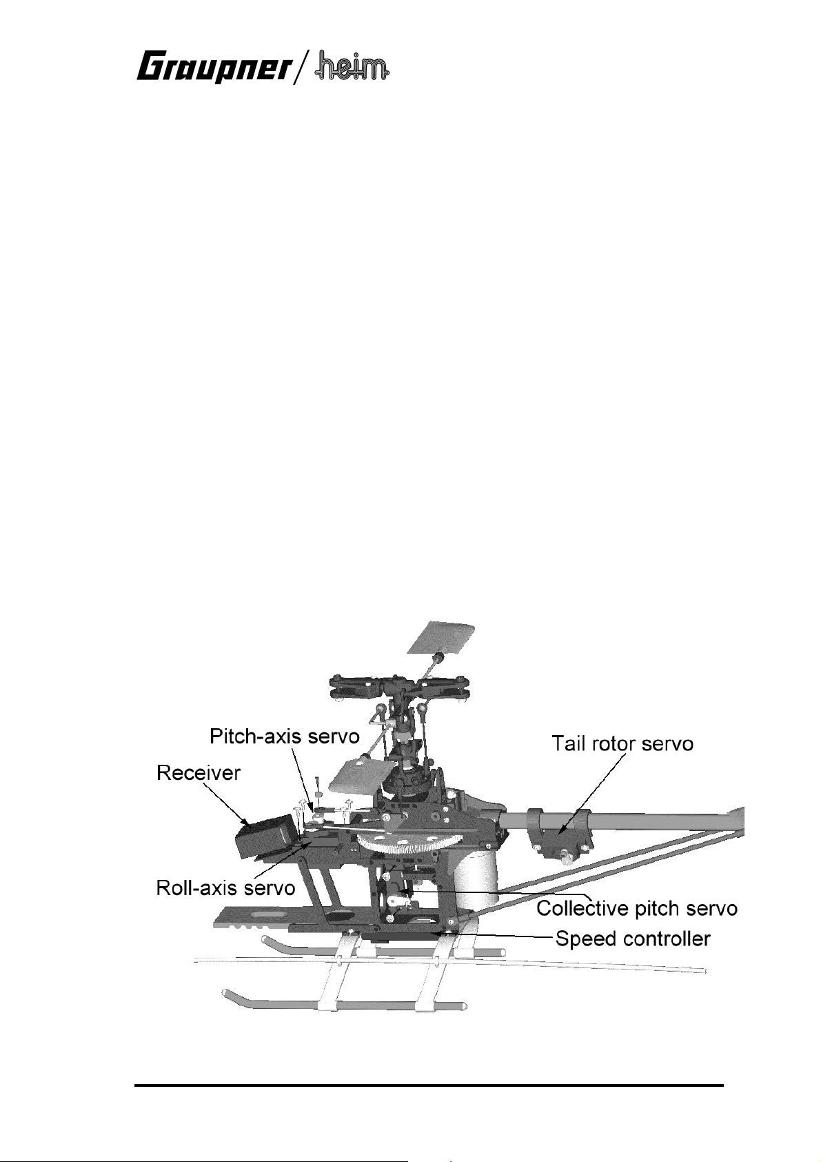
1.1 Installing the radio control system components
The arrangement of the radio control system components is shown in the illustration: The
servos are fixed to the chassis as shown in the drawing, using the screws supplied with them.
7
Page 8
Micro Star 400 v2
Connect the pushrods to the output arms of the swashplate, collective pitch and tail rotor
servos.
Important:
The servos must be set to centre (neutral) before fitting the output arms.
This is done by connecting the receiving system components including a receiver battery, then
switching on the transmitter and receiver. Check that all sticks and trims are at centre.
The basic collective pitch setting is established by adjusting the pushrod which runs up through
the main rotor shaft. Loosen the control rocker clamping screw to adjust this setting. Adjust the
pushrod so that the pitch angle of the blades is 0 … 3° when the servo is at centre and the
rocker is horizontal.
8
Page 9
Micro Star 400 v2
Adjust the position of the tail rotor servo until the tail rotor control lever is exactly at right-angles
to the tail boom when the servo is at neutral.
9
Page 10

Micro Star 400 v2
Connect the speed controller to the motor as described in the instructions supplied with it. Keep
the cables as short as possible, and ensure that there is no short-circuit between the pins of the
suppressor capacitors (soldered to the motor terminals) and the motor case.
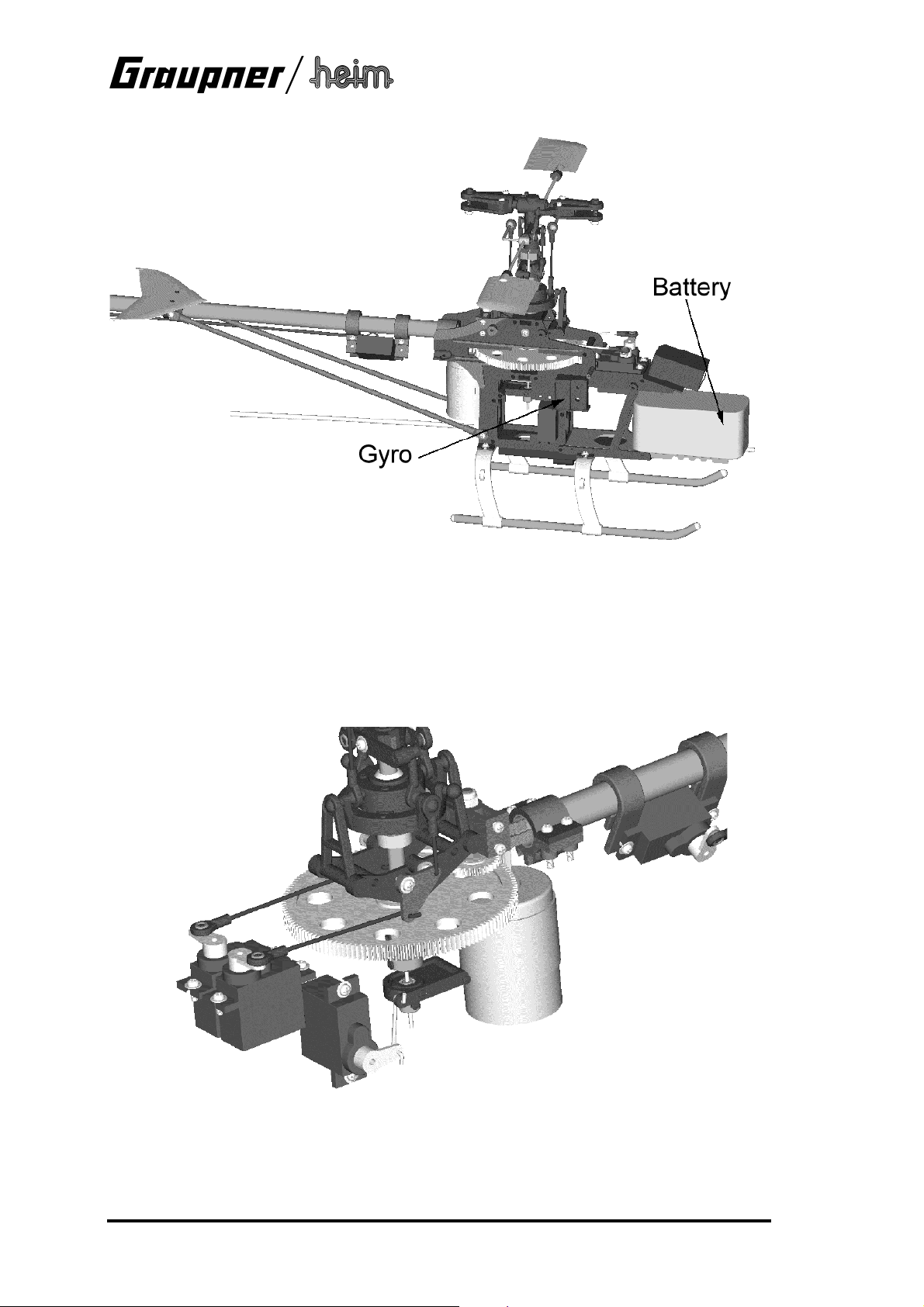
The flight battery, which also provides power to the receiving system via the BEC circuit
incorporated in the speed controller, is connected to the system by a plug and socket. This
connection should be positioned for easy access even when the cabin is in place, because the
plug and socket serve as the ON / OFF switch for the receiving system, as well as the flight
battery charge socket.
The flight battery is installed at the bottom of the chassis at the front, as shown in the drawing;
ensure that it is pushed fully into place; this will ensure that the Centre of Gravity (directly below
the main rotor shaft) is correct when the cabin is fitted. When you are satisfied, group the cables
together so that the cabin can be fitted without fouling anything.
10
Page 11

Micro Star 400 v2
2. Setting up
2.1 Setting up the cyclic control system
The basic settings for the roll-axis and pitch-axis control systems should already be correct if
you have installed the linkages exactly as described in the instructions. Since the lever lengths
are pre-defined, the final setting up is carried out using the electronic facilities provided by your
transmitter.
2.2 Main rotor pitch settings
The main rotor pitch is measured using the pitch gauge included in the kit. The following table
shows the recommended basic settings, but the optimum values may well vary slightly
according to your particular model and the rotor blades you are using.
Minimum Hover Maximum
Hovering and practice -1° 3°...4° 7°
Aerobatics -7° 0° 7°
Auto-rotation -1° 3° 8°
The best way of setting the correct blade pitch on the transmitter is as follows:
1. Measure the hovering pitch and set it to the correct value
2. Measure collective pitch maximum and minimum and adjust the values according to the
following diagrams, using your transmitter's collective pitch curve facility
11
Page 12

Micro Star 400 v2
2.3 Setting up the motor control system
The following diagrams show two alternative motor control curves:
The "normal" power curve is suitable for hovering and circuits.
•
The "aerobatic" power curve is set up in such a way that the motor does not stop at any
•
position of the collective pitch stick. This means that this curve must only ever be selected
when the model is already flying.
The values stated above can only be a guideline as they vary greatly according to the motor
•
in use. There is no alternative but to fine-tune them during the test-flying programme.
2.4 Further adjustments
If you have made up all the linkages exactly as described in the previous sections, no changes
to the mechanical arrangements will be necessary. The following adjustments can all be carried
out at the transmitter:
1. Servo direction
Set the "sense" (direction of rotation) of all servos as stated in the instructions. Check the
speed controller in particular!
2. Dual Rates
You can set switchable travels for roll-axis, pitch-axis and tail rotor. As a starting point we
recommend 100% and 75% as the two Dual Rate settings
3. Exponential
For the basic set-up you should leave all control systems set to "linear".
4. Servo travel centre offset
Do not make any adjustments to this point. At a later stage you may wish to make minor
corrections here.
5. Adjusting servo travel
This is where you can adjust the maximum servo travel. Note that the travels should always
be the same on both sides of neutral, otherwise you will end up with unwanted differential
effects:
12
Page 13

Micro Star 400 v2
The collective pitch servo should produce a range of blade pitch angles covering -8° to +9°,
with symmetrical travels; you may find it necessary to remove the servo output arm, move it
round by one spline and fit the retaining screw again. When the collective stick is at centre
(hover point), collective pitch should be about 3°, and the speed controller should be at the
"half-throttle" position.
Note:
The collective pitch and power curves can be adjusted later to meet your exact personal requirements. However, if you have already set differential travels in the basic set-up procedure, as shown in diagram "B" above, any fine adjustments required subsequently will be
more difficult!
6. Collective pitch and power curves
These adjustments are of fundamental importance to the flight performance of any model
helicopter. The aim of the procedure is to maintain a constant rotor speed when the model is
climbing and descending, i.e. regardless of load. This then represents a stable basis for further fine-tuning, e.g. of the torque compensation system etc. (see also "Collective pitch and
throttle curves").
7. Static torque compensation
The tail rotor servo is coupled to the collective pitch function via a mixer in the transmitter in
order to compensate for changes in torque when you operate the collective pitch control. On
most transmitters the mixer input can be set separately for climb and descent. Recommended values for the basic settings are: climb: 35%, descent: 15%.
8. Gyro adjustment
Gyro systems damp out unwanted rotational movements around the vertical (yaw) axis of the
model helicopter. They do this by detecting the unwanted motion and injecting a compensatory signal into the tail rotor control system, and in order to achieve this effect the gyro electronics are connected between the tail rotor servo and the receiver.
The gyro systems recommended for the Micro Star 400 v2 either feature a gain adjustor,
which should initially be set to 50% gain, or alternatively the gyro gain can be adjusted from
the transmitter using a supplementary channel (see gyro system instructions).
Check that the direction of the gyro’s compensatory action is correct, i.e. that it responds to a
movement of the tail boom with a tail rotor movement in the opposite direction. If this is not
the case, any yaw movement of the model would be amplified by the gyro! If it works the
wrong way round, the solution is to operate the reverse switch on the gyro, or mount the gyro
inverted.
One factor which is common to all gyro systems is that flight testing is necessary in order to
establish the optimum settings, as so many different factors influence them.
The aim of the gyro adjustment process is to achieve as high a level of stabilisation as possible without the gyro causing the tail boom to oscillate.
3. Final checks before the first flight
When you have completed the model, please run through the final checks listed below before
the first flight:
Study the manual again and ensure that all the stages of assembly have been completed
•
correctly.
Check that all the screws in the ball-links and brackets are tightened fully after you have
•
adjusted gear meshing clearance.
Can all the servos move freely, without mechanical obstruction at any point? Do they all
•
rotate in the correct direction relative to the stick movements? Are the servo output arm
retaining screws in place and tight?
Check the direction of effect of the gyro system.
•
Ensure that the transmitter and flight batteries are fully charged.
•
Don’t attempt to fly the helicopter until you have successfully checked everything as described
above.
13
Page 14

Micro Star 400 v2
4. Adjustments during the first flight
Blade tracking
The term "blade tracking" refers to the height of the two rotor blades when they are spinning.
The adjustment procedure aims at fine-tuning the pitch of the main rotor blades to exactly the
same value, so that the blades rotate at the same level.
Incorrectly set blade tracking, with the blades revolving at different heights, will cause
the helicopter to develop serious vibration in flight.
When you are adjusting the blade tracking, please keep at least 5 metres away from the
model in the interests of safety.
You can only check blade tracking if you are able to see clearly which blade is higher and which
is lower. The best method is to mark the blades with coloured tape as follows:
There are two alternative methods: figure "A" shows the use of different colours on the blade
tips; fig. "B" shows the use of the same colour, but applied at different distances from the tip.
Procedure for adjusting blade tracking:
1. Set the helicopter to the point where it is almost lifting off, then sight directly along the rotor
plane.
2. If you can see that the rotor blades are running in the same plane, no adjustment is required;
however, if one blade is running higher than the other, the settings must be corrected.
3. Locate the pushrods between the blade holders and the mixer levers; the adjustment is
made at the ball-links on both ends of these pushrods: unscrew the links to raise the blade,
screw them in to lower it.
14
Page 15

Micro Star 400 v2
5. Maintenance
Helicopters, whether large or small, place considerable demands on maintenance. Whenever
you notice vibration in your model, take immediate steps to reduce or eliminate it. Rotating
parts, important screwed joints, control linkages and linkage junctions should be checked before
every flight. If repairs become necessary, be sure to use original replacement parts exclusively.
Never attempt to repair damaged rotor blades; replace them with new ones.
Since the model is supplied factory-assembled, you will not have acquired any particular knowledge about its construction.
The following section therefore describes the procedure for assembling the model from its component parts; this may be important for subsequent maintenance and repair work.
5.1 Assembling the model from components
The main rotor shaft is supported in two ballraces, and the first step is to fit them in the chassis
side frames. Fix the two chassis frames together permanently using the appropriate self-tapping
screws.
Install the battery holder 4441.326 and screw it to the chassis. Attach the tail boom holder at the
same time: fit the top and bottom sections for the toothed-belt version; the shaft-drive version
only requires the top section.
Press the freewheel bearing into the main gear 4441.23 (check the correct direction!), then slide
the freewheel sleeve into place as shown. Install this assembly in the chassis.
15
Page 16

Micro Star 400 v2
Install the pitch-axis rocker, the roll lever and the collective pitch lever, and secure them as
shown; check that everything works smoothly and freely; if not, loosen the screws "M" by half a
turn.
Belt-drive version only:
Press the two bearings into the toothed belt drive bracket 4441.329, then fit the front belt pulley
4441.333 as shown, and secure it with the self-locking nut. Slide this assembly into the guide
rails in the chassis and fit the retaining screws.
16
Page 17

Micro Star 400 v2
Assemble the main rotor head and rocker (4441.65), together with the remaining parts such as
the blade holders 4441.61, the feathering spindle 4441.66, the driver 4441.368, the washout
unit 4441.332 and the main rotor shaft 4441.22, as shown in the illustration. Check all levers
and links for freedom of movement. Loosen the screws "N" by half a turn if necessary.
Position the collective pitch control slider "P" with the hole at the bottom, then slide it into the
washout unit and the slot in the main rotor shaft. Slide the collective pitch pushrod 4441.334 into
the main rotor shaft, threaded end first, and screw it into the slider "P" by about seven full turns.
Check for freedom of movement; if necessary, rotate the driver 4441.368 slightly to correct any
stiffness.
Assemble and install the flybar with the control levers 4441.62, the paddle adaptors 4441.364
and the Hiller paddles 4441.63. Set the flybar exactly central in the rotor head.
Fit the swashplate 4441.31 on the main rotor shaft, then set the pushrods 4441.391 to the
lengths stated in the drawing, and connect them as shown.
17
Page 18

Micro Star 400 v2
Slide one of the two collets on the main rotor shaft, and fit the whole assembly through the ballraces in the chassis from above, and through the main gear. Fit the second collet on the bottom
end, position it flush with the bottom end of the main rotor shaft, and tighten the retaining screw.
Pull the shaft up as far as it will go, slide the top collet down until it rests on the upper ballrace,
then tighten the retaining screw in the top collet.
Fit the collective pitch pushrod into the clamp of the collective pitch lever, and tighten the
clamping screw. Ensure that full symmetrical control travel is available on both sides of the centre position of the lever. Connect the swashplate linkages to the swashplate to complete this
section.
Install the motor 4441.21 in the chassis from the underside, and secure it with the retaining
screws. Assemble the skid landing gear from parts 4441.305 and 4441.306, and fix it to the
chassis using the self-tapping screws supplied. Align the skid tubes 4441.306 carefully, then fix
them to the skid bars 4441.305 using small self-tapping screws or cyano.
18
Page 19

Micro Star 400 v2
Press the ballraces 4441.46 into the shells of the tail rotor housing 4441.347, fit the tail rotor
shaft 4441.344 and engage the toothed belt 4441.317, then screw the two housing shells
together. Install the bellcrank 4441.343 and the control bridge 4441.42.
Each tail rotor blade 4441.41 is secured using an M2 screw with a ballrace fitted on it. Fit the
screws in the hub 4441.45 and at the same time fix them to the tail rotor shaft by tightening
them over two opposed flats in the hex-section shaft. Tighten the screws fully.
19
Page 20

Micro Star 400 v2
Fit the two clamps 4441.311 and the servo mounts 4441.308 on the tail boom 4441.310, then
screw the vertical and horizontal stabilizers 4441.04 to the clamps. Draw the toothed belt
through the boom (taking care not to twist it), and push the tail rotor onto the end of the boom.
Install the tail rotor blades 4441.02 in the blade holders as shown in the drawing; check that
they swivel freely.
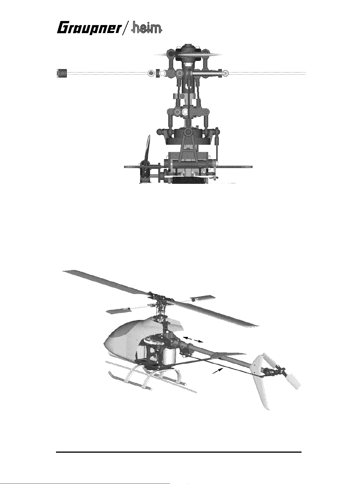
The tail boom is installed as shown in the illustration below:
Undo the four retaining screws from the chassis, and remove the bracket and front belt pulley.
Loosen the top section of the tail boom support to the point where the tail boom can be slid into
place (1).
Rotate the toothed belt through 90° in the direction shown (2).
Engage the belt pulley in the toothed belt, and re-fit the tail rotor drive assembly in the chassis
(3).
Pull the tail boom back to place the toothed belt under tension, then tighten the screws in the tail
boom support (4).
20
Page 21

Micro Star 400 v2
Install the two tail boom braces 4441.307 as shown in the picture. Fit the aerial guide sleeve
through the holes in the skid bars.
The rotor blades and canopy are fitted after the receiving system components have been installed; this procedure has already been described.
Option: CFRP shaft-driven tail rotor:
Locate the plain ballrace (no flange) from the ballrace set 4441.316 and slide it into position approximately half-way along the tail boom 4441.310. It should be fixed in place either by lightly
centre-punching the outside of the tail boom on both sides of the bearing, or gluing it in the
boom.
Fit the rear flanged ballrace on the drive shaft 4441.312, with the flange facing the bevel gear
and resting against it. Glue the inner ring of the bearing to the shaft. When the glue has cured,
slide the shaft into the tail boom and through the centre bearing until the flange of the rear
bearing rests against the end of the boom, then carefully push the front bearing in as far as it
will go. Fit the crown gear 4441.314 on the front end of the shaft, press it against the front
bearing and tighten the grubscrew to secure it.
21
Page 22

Micro Star 400 v2
Only the bottom section of the tail boom support is used to fix the tail boom to the chassis in this
version; it is fitted on top of the boom, while the bottom of the boom rests directly on the chassis; this places the drive shaft in the correct position relative to the motor pinion.
Note:
The tail boom is located lower in the chassis than with the toothed-belt version, with the result
that the crown gear only engages with the top of the motor pinion:
Fit the shaft 4441.444 (with bevel gear) in the tail rotor gearbox instead of the shaft 4441.344
(with toothed belt pulley).
22
Page 23

Micro Star 400 v2
6. General safety measures
Take out adequate third-party insurance cover.
•
Wherever possible join the local model flying club.
•
At the flying site:
Never fly your model above spectators.
•
Do not fly models close to buildings or vehicles.
•
Avoid flying over agricultural workers in neighbouring fields.
•
Do not fly your model in the vicinity of railway lines, major roads or overhead cables.
•
Pre-flight checks, flying safety:
Before you switch on the transmitter, check carefully that no other model flyer is using the
•
same frequency.
Carry out a range check with your RC system.
•
Check that the transmitter and flight batteries are fully charged.
•
Do not let the model fly out of safe visual range.
•
Post-flight checks
Clean the model and check that all screws etc. are still tight.
•
Examine the helicopter carefully for wear and damage, and replace worn parts in good time.
•
Ensure that the electronic components such as battery, receiver, gyro etc. are still securely
•
fixed. Remember that rubber bands deteriorate with age and may fail.
Check the receiver aerial. Conductor fractures inside the insulation are often not visible from
•
the outside.
If the main rotor should touch the ground when spinning, be sure to replace the blades.
•
Internal blade damage may not be visible from the outside!
Never carry the model by the tail boom: too firm a grip will easily deform the tail rotor
•
pushrod.
7. Some basic terms used in model helicopter flying
The term "rotary wing machine" indicates that the helicopter’s lift is derived from rotating "wings"
which take the form of rotor blades. As a result, a helicopter does not require a minimum forward speed in order to fly, i.e. it can hover.
Cyclic pitch
Cyclic pitch variation is used to steer the machine around the roll and pitch axes. Changing cyclic pitch has the effect of altering blade pitch depending on its position in the circle. The effect
is caused by tilting the swashplate, which then effectively tilts the helicopter in the required direction.
Collective pitch
Collective pitch provides control over vertical movement, i.e. for climb and descent. The pitch of
both rotor blades is altered simultaneously.
Torque compensation
The spinning rotor produces a moment which tends to turn the whole helicopter in the opposite
direction. This effect must be accurately neutralised, and this is the task of the tail rotor. Tail
rotor blade pitch is altered to vary torque compensation. The tail rotor is also used to control the
model around the vertical (yaw) axis.
Hovering
This is the state in which the helicopter flies in a fixed position in the air, without moving in any
direction.
23
Page 24

Micro Star 400 v2
Ground effect
This occurs only when the machine is close to the ground, and it falls off as altitude rises. At an
altitude of about 1 - 1½ times the rotor diameter ground effect is completely absent. Normally
the revolving airflow from the main rotor is able to flow away freely, but in ground effect the air
strikes an obstacle (the ground) and forms an "air cushion". In ground effect a helicopter can lift
a greater weight, but its positional stability is reduced, with the result that it tends to "break
away" in an unpredictable direction.
Climb
Any excess power above that required for hovering can be exploited to make the helicopter
climb. Note that a vertical climb requires more energy than an angled climb which includes
forward motion. For this reason a model with a given amount of motor power will climb more
rapidly at an angle than vertically.
Level flight
A helicopter absorbs least power when flying straight and level at about half-throttle. If you have
trimmed the machine carefully for a steady hover, it will tend to turn to one side when flown forward. The reason for this phenomenon is that the rotor blade which is moving forward encounters an increased airflow caused by the wind, and this increases its upthrust compared to the
blade which is moving downwind, where the same airflow has to be subtracted. The net result is
a lateral inclination of the helicopter.
Descent
If the helicopter’s rotor speed is relatively low and you place the helicopter in a fast vertical descent, the result can be that insufficient air flows through the rotor. This can cause what is
known as a "turbulent ring stage", when the airflow over the blade airfoil breaks away. The helicopter is then uncontrollable and will usually crash. A high-speed descent is therefore only possible if the helicopter is moving forward, or if the rotor is spinning at high speed. For the same
reason care should be exercised when turning the model helicopter downwind after flying into
wind.
Flapping motion of the rotor blades
As we have already seen, the forward-moving blade produces greater upthrust than the trailing
blade. This effect can be minimised by allowing the leading blade to rise and the trailing blade to
fall. The rotor head is fitted with what is known as a flapping hinge to allow this movement, and
this prevents the rotor plane tilting excessively in forward flight. In model helicopters a single
hinge shared by both blades has proved an effective solution to the problem.
Auto-rotation
This term refers to a helicopter flying without motor power. The rotational speed of the main rotor can be kept high by setting both blades to negative pitch, and the airflow through the rotor as
it descends then keeps the blades turning. The rotational energy stored in the rotor by this
means can be converted into upthrust if the pilot applies positive collective pitch when the helicopter is close to the ground. Of course, this can only be done once, and it has to be done at
the correct moment. Auto-rotation allows a model helicopter to land safely when the motor fails,
just like a full-size machine.
However, auto-rotation places considerable demands on the pilot’s judgement and reflexes; you
can only halt the machine’s descent once, and you must not "flare" too early or too late. Plenty
of practice is required to get it right.
24
Page 25

Order No. 4495
4496
Micro Star
400 v2
Summary of
replacement parts
Date of issue 12/2005
GRAUPNER GmbH & Co. KG D-73230 KIRCHHEIM/TECK GERMANY
Modifications, errors and printing errors reserved. ID# 56503 12/05
Page 26

Replacement parts
Micro Star 400 v2
Graupner
Order No.
4441.01 Main rotor blade, plastic 2
4441.02 Tail rotor blade, plastic 2
4441.303 Cabin and glazing 1
4441.04 Horizontal / vertical stabilizers 1 each
4441.305 Skid bar 2
4441.306 Skid tube, black aluminium 2
4441.307 Tail boom strut, CFRP 2
4441.308 Tail rotor servo mount, plastic 2
4441.310 Tail boom, black aluminium 1
4441.311 Tail boom bracket, plastic, 10 mm 2
4441.312 Tail rotor drive shaft with bevel pinion, CFRP 1
4441.314 Crown pinion C, plastic 2
4441.15 Motor pinion, brass, 10-tooth 1
4441.316 Ballrace set, tail rotor drive shaft (3 bearings) 1
4441.317 Toothed belt for tail rotor drive system 1
4441.320 Mechanics chassis, V2 1
95168 Ballrace for main rotor shaft, 5 x 10 x 4 1
4441.21 Drive motor and pinion 1
4441.22 Main rotor shaft, aluminium 1
4441.23 Main gear 1
4441.24 Hub and freewheel 1
4441.325 Bellcrank set, pitch-axis 1
4441.326 Battery holder, aluminium 1
4441.329 Tail rotor drive bracket (toothed belt), w/ bearings 1
4441.30 Roll-axis / collective pitch bellcrank set 1
4441.31 Swashplate 1
4441.332 Washout unit 1
4441.333 Tail rotor drive system (toothed belt) 1
4441.334 Collective pitch pushrod 2
Description Dimensions
[mm]
No. off
Reqd./Pack
4441.41 Tail rotor blade holder 2
4441.42 Control bridge, complete 1
4441.343 Bellcrank 1
4441.344 Tail rotor shaft and toothed belt pulley 1
4441.444 Tail rotor shaft and bevel pinion (V2) 1
4441.45 Tail rotor hub 1
4441.46 Ballrace 2
4441.347 Tail rotor housing (10 mm) 1
4441.61 Main rotor blade holder 2
4441.62 Flybar with control levers 1
4441.63 Hiller paddle 2
4441.364 Paddle adaptor 2
4441.65 Rotor head centre piece and rocker 1
4441.66 Feathering spindle 1
4441.67 Ballrace 1
4441.368 Washout unit driver, aluminium 1
4441.90 Screw set 1
4441.391 Pushrod and ball-link set 1
2
Page 27

Optional upgrade components
Micro Star 400 v2
Graupner
Order No.
4441.101 Main rotor blade, CFRP 2
4441.201 Main rotor blade, GRP 2
4441.102 Tail rotor blade, CFRP 2
4441.105 Trainer landing gear 1
4441.410 Tail boom (10 mm), CFRP 1
4441.420 Mechanics chassis, CFRP / aluminium 1
4441.122 Main rotor shaft, steel 1
4441.125 Pitch-axis bellcrank set, aluminium 1
4441.130 Roll bellcrank set, aluminium 1
4441.131 Swashplate, aluminium 1
4441.132 Washout unit, aluminium 1
4441.160 Main rotor head centre piece and rocker,
aluminium
4441.161 Main rotor blade holder, aluminium, with bushes 2
4441.163 Hiller paddle, CFRP 2
Description Dimensions
[mm]
No. off
Reqd./Pack
1
3
Page 28

Notes
Micro Star 400 v2
4
 Loading...