

Page 1
Micro Star
Order No. 4487
1000
Electric Model Helicopter
Order No. 4487 Kit-form model including
brushless electric motor
Warning!
The contents of this kit can be assembled to produce a working helicopter, but the model
is by no means a harmless plaything. If assembled incorrectly or handled incompetently
or carelessly it can cause serious injury to persons and damage to property.
You alone are responsible for completing the model correctly and operating it safely.
Please be sure to read any information sheets containing safety notes included in the kit,
as they are an essential part of these instructions
GRAUPNER GmbH & Co. KG D-73230 KIRCHHEIM/TECK GERMANY
Modifications, errors and printing errors reserved ID# 61792 06/10
Page 2

Micro Star 1000
Foreword
The “Micro Star 1000” is a fully aerobatic electric-powered model helicopter with a high excess
of performance. It is suitable for beginners, more advanced pilots and experts alike, and offers
the following outstanding features:
• Partly pre-assembled
• Powered by brushless electric motor
• Motor included
• Right-hand rotation main rotor
• Toothed belt tail rotor drive system
• Auto-rotation freewheel
• Designed for three-cell LiPo flight battery
The potential flight time per battery charge naturally varies according to the model’s set-up and
the pilot’s flying style; our experience shows that a duration of around eleven minutes is possible
under normal conditions if the recommended LiPo battery is used.
The control functions roll, pitch (elevator) and collective pitch are mixed electronically, which
means that the model can only be flown with a suitably featured radio control system which has
special helicopter options.
The model’s strong, lightweight chassis consists of a combination of carbon fibre sheet parts,
machined aluminium components and some plastic items. The motor drives the main rotor by
means of a single-stage gearbox, which also features an integral auto-rotation freewheel as
standard.
Specification
Length excl. rotor approx. 880 mm
Height approx. 295 mm
Width excl. rotor approx. 150 mm
Main rotor Ø 960 mm
All-up weight min. approx. 1700 g
Main rotor reduction ratio 6.1 : 1
2
Page 3

Micro Star 1000
Warning notes
• The contents of this kit can be assembled to produce a working helicopter, but the
model is by no means a harmless plaything. If assembled incorrectly or handled in-
competently or carelessly it can cause serious personal injury and property damage.
• When the model helicopter’s motor is running, the two rotors spin at high speed and
contain an enormous quantity of rotational energy. Anything that gets into the rota-
tional plane of the rotors is either destroyed or seriously damaged - and that includes
parts of your body. Please take extreme care at all times with this machine.
• If any object impedes the rotational plane of the revolving rotors, severe damage will
probably be caused to the rotor blades as well as to the object. Broken parts may fly
off and cause enormous imbalance; the whole helicopter then falls into sympathetic
vibration, you lose control and have no way of predicting what the model will do next.
• You may also lose control if a problem arises in the radio control system, perhaps as a
result of outside interference, component failure or flat or faulty batteries, but in any
case the result is the same: the model helicopter’s response is entirely unpredictable.
Without prior warning it may move off in any direction.
• Helicopters contain many parts which are by their nature subject to wear, including
the gearbox, motor, ball-links etc., and as a result it is essential to check and maintain
the model regularly. It is standard practice with full-size aircraft to give the machine a
thorough “pre-flight check” before every flight, and this is equally important with your
model helicopter. Constant checking gives you the opportunity to detect and correct
any faults which may develop before they become serious enough to cause a crash.
• The kit may also include additional information sheets which contain safety notes and
warnings. Please be sure to read them and keep to our recommendations; these
sheets are an essential part of the instructions.
• This helicopter is designed to be assembled and operated by adults, although young
people of sixteen years and over may do so under the instruction and supervision of a
competent adult.
• The model features sharp points and edges which are capable of causing injury.
• The flying of model aircraft is subject to certain legal restrictions, and these must be
observed at all times. For example, it is essential to obtain permission to use your
chosen flying site, and you may have to obtain a licence to use your radio control
system (regulations vary from country to country). It is now a legal requirement to take
out third party insurance to cover the risks inherent in model flying.
• It is important to transport your model helicopter (e.g. to the flying site) in such a way
that there is no danger of damaging the machine. Particularly vulnerable areas are the
rotor head linkages and the tail rotor generally.
• Controlling a model helicopter successfully is not a simple skill; you will need persis-
tence to learn the art, and good hand - eye co-ordination is a basic requirement.
3
Page 4

• Before you attempt to fly the model we recommend that you study the subject of heli-
copters in depth, so that you have a basic understanding of how the machines work.
Read everything you can on the theory of rotary-wing aircraft, and spend as much
time as possible watching other model helicopter pilots flying. Talk to chopper pilots,
ask their advice, and enrol at a specialist model flying school if you need to. Many
model shops will also be prepared to help you.
• Please be sure to read right through these instructions before you start work on the
model. It is important that you clearly understand each individual stage of assembly
and the correct sequence of events before you begin building.
• Don’t make modifications to the model’s construction by using parts other than those
specifically recommended, unless you are certain of the quality and suitability of these
alternative parts for the task.
• We have made every effort to point out the dangers inherent in operating this model
helicopter. Since neither we, the manufacturer, nor the model shop that sold you the
kit have any means of ensuring that you build and operate your model correctly and
Micro Star 1000
competently, we are obliged to disclaim any liability in connection with it.
Liability exclusion / Compensation
As manufacturers, we at GRAUPNER are not in a position to influence the way you build
and set up the model, nor how you install, operate and maintain the radio control system
components. For this reason we are obliged to deny all liability for loss, damage or costs
which are incurred due to the incompetent or incorrect use and operation of our prod-
ucts, or which are connected with such operation in any way.
Unless otherwise prescribed by binding law, the obligation of the GRAUPNER company
to pay compensation, regardless of the legal argument employed, is limited to the invoice
value of that quantity of GRAUPNER products which was immediately and directly in-
volved in the event in which the damage occurred. This does not apply if GRAUPNER is
deemed to be subject to unlimited liability according to binding legal regulation on ac-
count of deliberate or gross negligence.
4
Page 5

Micro Star 1000
Instructions and warnings relating to the use of LiPo batteries
General information
Lithium-Polymer batteries (generally abbreviated to ‘LiPo batteries’) must be handled with particular care and
attention. This applies both to charging / discharging, and to storage and handling generally. It is important to
observe the following points at all times:
Mishandling these batteries incurs a risk of explosion, fire, smoke and poisoning. Ignoring or neglecting the instructions
and warning information can also cause loss of performance and other forms of defect.
The capacity of all LiPo batteries diminishes with every charge / discharge cycle. If they are stored at excessively high
or low temperatures they may also suffer a gradual loss of capacity. In modelling applications the batteries are subjected to motor induction currents as well as high discharge rates, with the result that you can expect their performance
to decline to around 50% to 80% of the capacity of a new pack after fifty charge / discharge cycles even if you observe
all the instructions regarding charge and discharge procedures.
Except in exceptional circumstances, LiPo packs must not be wired in series or parallel, as the packs may have different cell capacities and be at different states of charge. For this reason battery packs supplied by us are carefully selected before sale.
Please store these instructions in a safe place, and pass them on to the new owner if you ever sell the product
Special notes regarding the charging of Graupner LiPo batteries
Since we at Graupner GmbH & Co. KG are not in a position to ensure that you charge and discharge the cells correctly,
we cannot provide any guarantee on the cells if you fail to charge or discharge them using the proper procedures.
When charging LiPo batteries it is essential to use approved battery chargers and the associated charge leads. Any
modification to the charger or charge leads may result in serious damage to the battery or the charger.
The maximum charge capacity must be limited to 1.05 times the battery capacity.
Example: 700 mAh battery = 735 mAh max. charge capacity
LiPo batteries must never be charged or discharged using equipment other than Graupner chargers / dischargers designed specifically for the purpose. These include the LiPo Charger 4, Order No. 6437, LiPomat 4
Plus, Order No. 6438, Ultramat 10, Order No. 6410, Ultramat 12, Order No. 6412, ULTRA DUO PLUS 30, Order
No. 6416 (in LiIon, LiMn or LiPo mode (late versions only)), or GMVIS-Commander, Order No. 94401 - software
version V2003 or later.
You may need an adapter lead (available separately) for connecting the pack to the charger.
Ensure that the number of cells, the final charge voltage and the final discharge voltage are set correctly on the
charger. If you are unsure of this, refer to the operating instructions supplied with your charger / discharger.
The intended purpose of the white multi-pin plug (cell-count + 1 terminal) attached to each LiPo pack is for
connecting the battery to the battery charger, Order No. 6438, or the LiPo Balancer, Order No. 6491; it can also
be useful for charging individual cells manually in order to balance a pack. Once again it may be necessary to
obtain an adapter lead (available separately) to connect the battery.
Supplementary notes on battery handling
The pack to be charged must be placed on a heat-resistant, non-flammable, non-conductive surface for charging. Remove inflammable or volatile materials from the area around the charging station. LiPo batteries must
always be supervised when charging is in progress.
As a basic rule LiPo batteries consisting of series-wired cells may only be charged if the voltage of the individual cells
does not differ by more than 0.05 V. If the voltage of individual cells varies by more than 0.05 V, it will be necessary to
charge or discharge individual cells in order to balance the cell voltages as accurately as possible.
Provided that these conditions are satisfied, Graupner LiPo batteries can be charged at a maximum rate of 2C (the
value of 1C corresponds to the cell capacity). Once the cells reach a maximum voltage of 4.2 V, the charge process
must continue at a constant voltage of 4.2 V per cell until the charge current falls below 0.1 to 0.2 A.
It is essential at all times to avoid cell voltages of more than 4.25 V, otherwise the cells concerned will be permanently damaged, and may even burst into flames. To avoid overcharging individual cells in the pack we recommend that you set the cut-off voltage on the charger at 4.1 V to 4.15 V per cell, as this ensures a longer useful life for the batteries.
After each charge process it is important to check whether any individual cell in the pack exhibits a voltage of more
than 4.2 V. All the cells in the battery must be at the same voltage. If the voltage of the individual cells varies by more
than 0.05 V, the cell voltage must be matched by charging or discharging individual cells. We recommend that you
charge cells individually at regular intervals in order to avoid overcharging them after protracted use in pack form.
Never charge battery cells with reversed polarity. If you connect and charge a LiPo pack with reversed polarity, abnormal chemical reactions take place which will render the battery unusable; at the same time it may burst or split, develop
smoke and even go up in flames. The permissible temperature range when charging and storing LiPo batteries is 0°C
to 50°C.
: LiPo cells should be stored with a residual charged-in capacity of 10 to 20%. If the voltage of the cells falls
Storage
below 3 V during storage, it is absolutely essential to top them up again to the 10 - 20% point. Deep-discharging LiPo
batteries, and storing them in the discharged state (cell voltage < 3 V), invariably renders them unusable.
5
Page 6

Special notes regarding the discharging of Graupner LiPo batteries:
A continuous current of around 6C represents no major problem for any Graupner LiPo battery. If you wish to use
higher discharge currents, please refer to the specifications printed in the catalogue.
Discharging LiPo packs to a point below 2.5 V per cell causes permanent damage to the cells, and must therefore be avoided at all costs. This means that you must switch the motor off the moment you detect a significant
decline in motor power. If the individual cells are at different voltages when discharged, the speed controller’s
low-voltage cut-off could be triggered too late, with the result that individual cells might be discharged to an
excessively low level.
Short-circuits must always be avoided. Permanent short-circuits will inevitably wreck the battery, and may also
cause high temperatures and a fire.
The temperature of the battery during the discharge process must never exceed 70°C. If you find that the pack
gets too hot in use, it is imperative that you improve the battery cooling measures, or reduce the rate of discharge. The pack’s temperature can easily be checked using the Infra-Red Thermometer, Order No. 1963.
Supplementary handling notes
Avoid short-circuits:
Never short-out a LiPo battery. ‘Shorts’ allow very high currents to flow, which in turn cause the cells to heat up. This
will lead to loss of electrolyte, gassing or possibly even an explosion. When handling Graupner LiPo batteries you can
avoid the risk of short-circuits by keeping the packs well away from any conductive surface or component.
Mechanical strength of the foil casing:
The laminated aluminium foil enclosing each cell can easily be damaged by any sharp object, such as a needle, pin,
knife, nail, motor terminal or similar object. Foil damage renders the battery unusable. For this reason the battery must
be installed in the model in such a way that the pack cannot be distorted or damaged even if the model crashes. Remember that the battery could burst into flames if short-circuited.
The foil casing can also be damaged by temperatures above 70°C, causing the cell to leak. This may result in loss of
electrolyte, rendering the battery unusable. If this should occur, be sure to dispose of the battery in the proper manner.
Mechanical shock:
In mechanical terms LiPo batteries are not as robust as batteries consisting of metal-cased cells. Always avoid subjecting these packs to mechanical shock such as dropping, striking, bending, cutting, tearing, deforming or drilling into the
laminated film foil. Never bend or twist a LiPo battery, and do not exert pressure on the battery or its connections.
Handling the cell terminals:
Please note that the battery terminals are not as robust as those of other battery types. This applies in particular to the
aluminium tags, which can easily break off. Never solder directly to the contact tags, as the conducted heat may damage the cells.
Cell connections:
It is not permissible to solder directly to the battery cells.
Direct soldering may cause heat-induced damage to the battery components such as the separator or isolator.
The only approved method of making connections to the battery terminals is industrial spot-welding. If a wire is missing
or torn off, a professional repair by the manufacturer or distributor of the cells is the only possible recourse.
Replacing individual battery cells:
Individual LiPo cells may only be replaced by the manufacturer or distributor. This intervention must not be attempted
by the user.
Do not re-use damaged cells:
Damaged cells must not be re-used under any circumstances.
Typical signs of damaged cells are: damage to the foil case, cell distortion, a smell of electrolyte or actual escaping
electrolyte. If you detect any of these indications, you must not re-use the battery.
Damaged or otherwise unusable cells constitute toxic waste. It is essential to dispose of them in the proper manner
General warnings
These batteries must not come into contact with fire or ashes. The cells must not be allowed to contact fluids such as
fresh water, salt water or drinks. Avoid contact with liquids of all types. Individual cells and batteries are by no means
toys, and must never be allowed to get into the hands of youngsters. Store cells and batteries well out of the reach of
children. Batteries must not be left within reach or in the vicinity of babies or toddlers. If a child should swallow a battery, call for a doctor or emergency medical assistance without delay. Batteries must not be placed in a microwave
oven, nor subjected to pressure: the results may be smoke and fire or worse.
Never attempt to dismantle Li-Po cells. Taking a battery apart can cause internal short-circuits, which could result in
gassing, fire, explosion and other problems.
The electrolyte and electrolytic fumes are injurious to health. Avoid direct contact with the electrolyte at all costs. If the
material gets in your eyes, on your skin or other part of your body, it is essential to wash the affected area immediately
with copious amounts of clean water. Consult a doctor as soon as possible thereafter.
Batteries installed in a device should always be removed from the apparatus if it is not to be used again in the immediate future. Always switch off such devices after use to avoid discharging the cells to a dangerous level. Recharge the
batteries in good time. Store batteries on a non-flammable, heat-resistant and non-conductive surface. If you allow a LiPo battery to become deep-discharged, it will inevitably be ruined, and must not be used again.
Micro Star 1000
6
Page 7

Micro Star 1000
Contents
• Foreword........................................... P.2
• Warnings ........... ................................ P.3
• Accessories, additional items required...................... P.8
• 1. Assembling the model................................ P.9
• 2. The set-up procedure................................. P.23
• 3. Final checks before the first flight........................ P.25
• 4. Adjustments during the first flight, blade tracking............. P.25
• 5. Maintenance....................................... P.26
• 6. General safety measures ............................. P.26
• 7. Basic helicopter terminology ........................... P.27
Notes on the instructions
We have invested considerable effort in producing these instructions, with the aim of ensuring
that your model helicopter will fly reliably and safely. Please take the trouble to follow the instructions step by step, exactly as described, as this guarantees a successful outcome. This applies
to you whether you are a relative beginner or an experienced expert.
• The comprehensive illustrations show how the model is assembled; be sure to read the in-
structions which accompany the drawings.
• All gears, bearings and moving joints must be greased or oiled carefully.
• You will find a list of replacement parts at the end of these instructions.
7
Page 8

Accessories
Recommended items for the Micro Star 1000
Radio control system: see the main Graupner catalogue
You will need a radio control system equipped with special helicopter options, or a microcomputer radio control system.
Servos: four digital servos
Gyro system: preferably a gyro system with heading-lock function
Speed controller: brushless controller, 40 ... 80 A
Flight battery: LiPo 3/2100 ... LiPo 3/3200 (25 C)
Set contents:
Micro Star 1000
Bag A: Main rotor head, collective pitch compensator, swash-
plate, main rotor shaft, screw set
Bag B: (unmarked) chassis side frames, carbon stabiliser pan-
els and carbon speed controller mount
Bag C: Chassis components, main gear, toothed belt pulley
Bag D: Servo installation components
Bag E: Tail boom with toothed belt and tail rotor gearbox
Bag F: Tail rotor head, tail rotor blades, pushrod guide
Bag G: Flybar, tail boom braces, tail rotor pushrod, small items
Bag H: Landing gear
Bag I: Pushrods
Bag K: Main rotor blades
(packed separately): Z-Power Z20A 1230 kV electric motor
Rotor blade support
8
Page 9
Micro Star 1000
1. Assembling the model
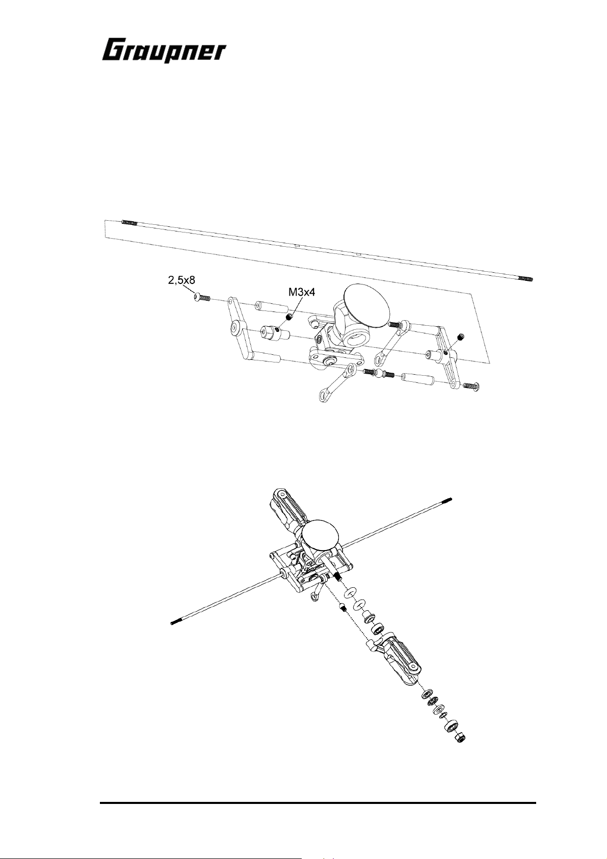
Remove the factory-assembled rotor head from bag “A”, together with the control bridge, which
consists of two halves; open the bag of screws at the same time.
Remove the flybar from bag “G”; it is 2 mm in diameter and around 29 cm long.
Insert the flybar through the halves of the control bridge and the rotor head rocker, as shown in
Fig. 1.
Connect the halves of the control bridge to each other using the two 2.5 x 8 mm self-tapping
screws, then position the flybar so that the two machined flats coincide with the threaded holes
in the annular clamps of the control bridge; tighten the two M3 x 4 grubscrews in this position,
checking that the grubscrews engage squarely on the flats.
Fig. 1 Installing the control bridge and flybar
Fix the rotor brake dish to the rotor head hub using the M3 x 12 round-head allen-head screw.
Fig. 2 shows how the blade holders are fitted, in case a repair ever becomes necessary; when
initially building the model you will find that these parts are factory-assembled:
Fig. 2 Main rotor blade holder and bearing assembly
9
Page 10
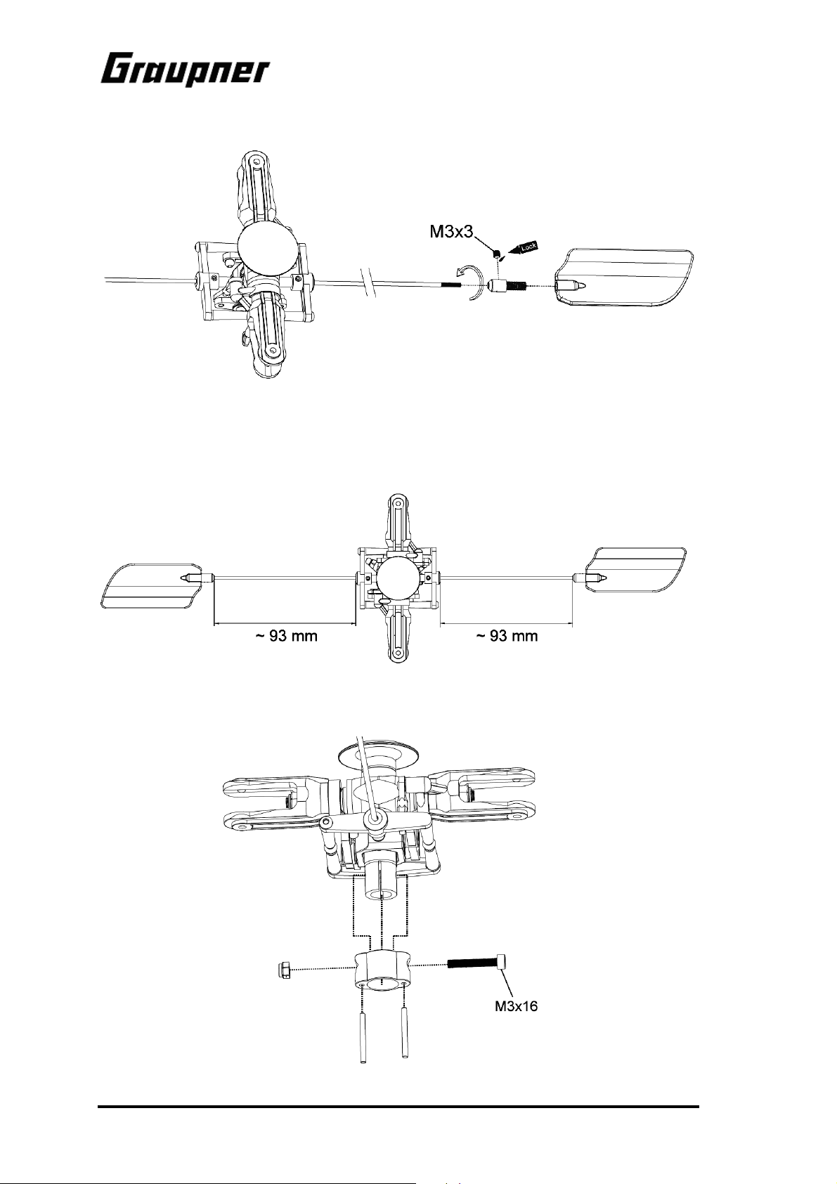
Screw the two Hiller paddles onto the ends of the flybar as far as they will go. Check that both
paddles are exactly the same distance from the centre of the rotor head.
Micro Star 1000
Fig. 3 Securing the flybar paddles
Align the flybar paddles parallel with each other and with the control bridge, as shown in the
drawing (right-hand main rotor rotation, i.e. clockwise), then tighten the two M3 x 3 grubscrews
to prevent the paddles rotating on the flybar.
Fig. 4 Centring the auxiliary rotor
Temporarily attach the factory-assembled swashplate driver to the main rotor head using an M3
x 15 socket-head cap screw and self-locking nut, as shown in Fig. 5.
Fig. 5 Attaching the main rotor head and swashplate driver
10
Page 11
Micro Star 1000
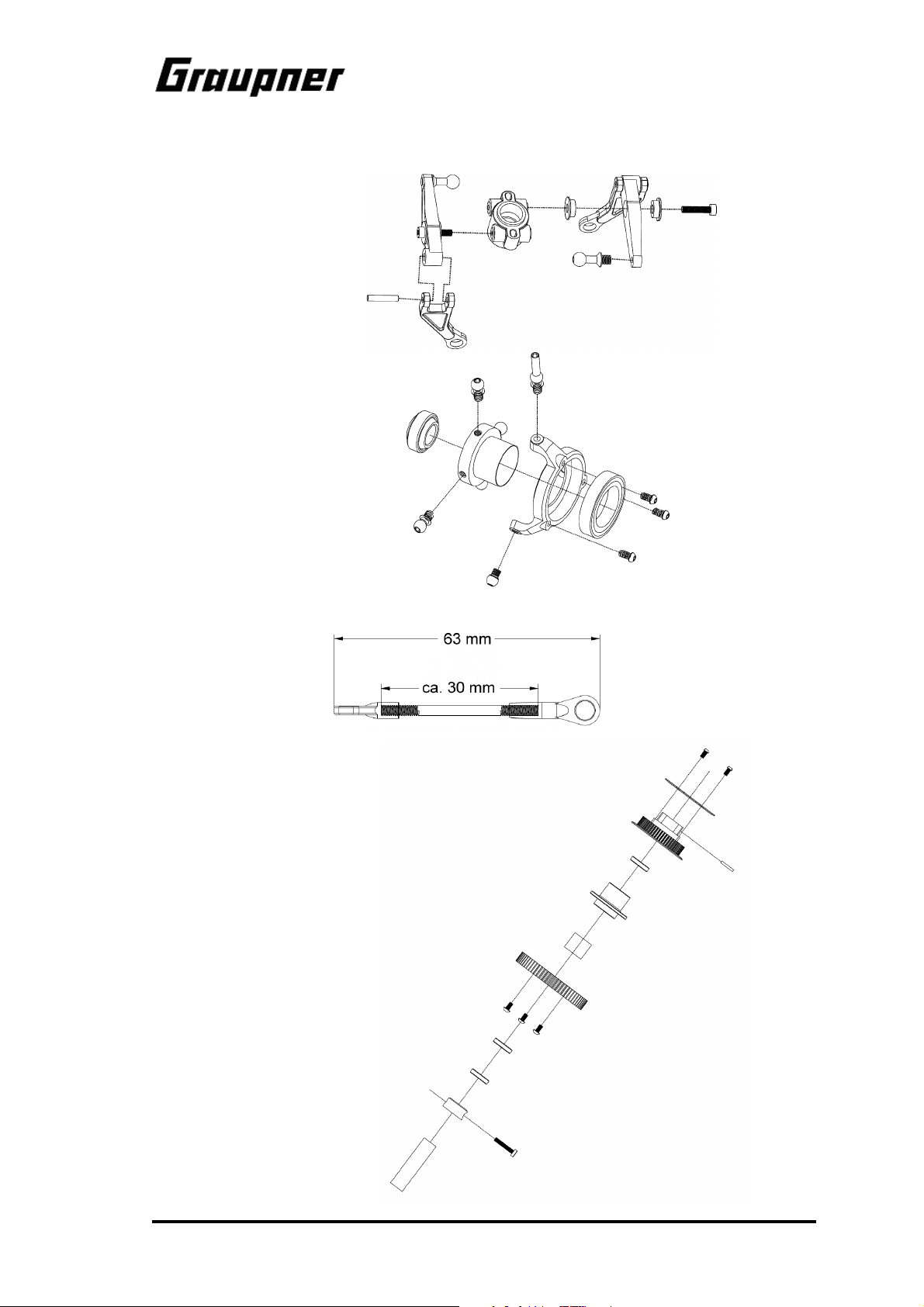
In the kit, the sub-assemblies shown below are supplied in pre-assembled form; the exploded
drawings are only required for repair and maintenance purposes:
Fig. 6: Collective pitch compensator
Fig. 7: Swashplate
Fig. 8: Swashplate -> rotor head pushrod
Fig. 9: Main gear with freewheel and toothed belt pulley
11
Page 12

As shown in Fig. 10, the sub-assemblies prepared thus far can now be fitted on the main rotor
shaft, which is found in bag “A”:
Micro Star 1000
Fig. 10: Main rotor and shaft (excl. rotor blades)
The lower collet with the two M3 x 4 grubscrews is supplied in bag “C”.
Please ensure that the main rotor shaft is fitted the right way round: the end with one transverse
hole is the top end, that with two transverse holes the bottom end. Check also that the rotor
head retaining screw actually passes through the upper transverse hole, and not above it.
The main rotor assembly, prepared to this stage, can now be placed to one side temporarily, as
can the main gear and the toothed belt pulley.
12
Page 13

Micro Star 1000
The next step is to assemble the main chassis from the parts in bags “C” and “D”, and also the
separately packed side frames from bag “B”; the procedure is shown in the drawings below.
When fitting the main rotor shaft bearing brackets please note that the bearings in the upper
bearing bracket face up, and those in the lower bearing bracket face down. One of the bearing
brackets features a through-hole on one side for the threaded rod; this is the upper bracket.
When installing the tail boom holder (two plastic brackets with semi-circular cut-outs) ensure that
the moulded-in locating lugs for the tail boom are located at the front (toward the nose).
.
Figs. 11, 12: Assembling the chassis and skids
13
Page 14

The bellcranks for the swashplate control system and the cabin supports should now be attached to the prepared chassis. The bellcranks are supplied with linkage balls and ballraces already fitted, and not separately as shown in the drawing:
Micro Star 1000
Fig. 13: Installing the bellcranks
Fig. 14 shows the method of mounting the tail rotor gearbox on the tail boom, and fitting the
toothed drive belt. The drawing is provided for the purpose of repair and maintenance; the kit
contains the factory-built sub-assembly in bag “E”.
Fig. 14: Tail boom and tail rotor gearbox
14
Page 15

Micro Star 1000
The individual sub-assemblies can now be brought together as shown in Fig. 15; please note the
following points: the tail rotor is on the right-hand side, as seen from the tail looking forward. The
tail rotor drive belt has to twist through 90° to the right (clockwise), as seen from the front (take
care not to turn it more than once !!!). Slide the tail boom into the holder in the chassis in such a
way that the two U-shaped cut-outs on either side of the tail boom engage in the locating lugs
moulded into the tail boom support; when you are satisfied that this is so, push the tail boom
forward as far as it will go, then tighten the four screws against the self-locking nuts in the
holder.
Now place the main gear and belt pulley in the chassis, wrapping the toothed belt round the pulley at the same time (don’t twist it - see above); guide it between the two tensioner pulleys.
Place the brass spacer ring between the main gear and the lower main rotor shaft bearing. Fit
the main rotor assembly through the upper rotor shaft bearing, the belt pulley, the main gear and
the spacer ring from above, and into the bottom rotor shaft bearing. Push the cross-pin through
the hole in the main rotor shaft, provided that the hole is still accessible above the belt pulley,
then press the shaft into the belt pulley to the point where the cross-pin engages full-depth in the
moulded-in channel in the belt pulley.
Fig. 15: Joining the main chassis, main rotor and tail boom sub-assemblies
Fit the freewheel sleeve onto the bottom end of the main rotor shaft (the end with the two crossholes is at the bottom), and slide it through the lower rotor shaft bearing into the freewheel of the
main gear to the point where the two cross-holes line up with the cross-holes in the rotor shaft.
Ensure that the lower rotor shaft bearing is pressed fully upward into the bearing bracket; the
grubscrews in the upper collet (below the swashplate) also have to be loosened to allow the rotor shaft to be pushed down far enough.
When the freewheel sleeve is correctly positioned on the rotor shaft, slide the lower collet into
place (with the shoulder at the top). Apply thread-lock fluid to the M3 x 14 socket-head cap
screw, fit it through the upper cross-holes, and tighten it firmly.
Now hold the chassis securely and pull the rotor head up as far as possible, pulling hard; in this
position press the upper collet firmly against the upper rotor shaft bearing. Tighten the two grubscrews securely in this position.
15
Page 16

Set the three pushrods to the stated lengths, and use them to connect the swashplate to the
bellcranks.
Fit the prepared tail rotor head on the tail rotor shaft, as shown in Fig. 16. Please note the following points:
The M3 x 3 grubscrew must engage in the depression in the tail rotor shaft; tighten it fully in this
position. The blade holder linkage point is at the leading edge of each rotor blade; bear this in
mind when assembling the blades and the control bridge.
Micro Star 1000
Fig. 16: Assembling the tail rotor head
Checking the installation:
If you rotate the main rotor clockwise as seen from above, the tail rotor should turn anticlockwise when viewed from the right-hand side; the lower tail rotor blade should move forward
(toward the nose), the upper blade should move aft. This tail rotor arrangement is known as
“lower blade advancing”.
16
Page 17

Micro Star 1000
The swashplate and tail rotor servos are installed using the fittings supplied in bag “D”, as shown
in drawings 17 and 18. Please note that the two pushrods for each push-pull linkage must be
exactly the same length. The lever length of the servo output arms must also be 12 mm, so that
the hole spacing is exactly the same as that of the bellcranks.
Figs. 17, 18: Installing the swashplate servos
The stated pushrod lengths are only a starting point, and you may need to adjust them slightly to
suit the servos you have installed. The absolute length is not very important; the crucial point is
that both pushrods must be exactly the same length.
17
Page 18

Micro Star 1000
Fig. 19: Installing the tail rotor servo
The drive motor is attached to the motor mount as shown in Fig. 20, which must first be removed from the chassis for this purpose. The moulding features slots for mounting the motor,
designed to enable the builder to set the requisite very slight meshing clearance between the
motor pinion and the main gear. Fix the pinion on the motor shaft with its top edge flush with the
top edge of the main gear; the grubscrew must engage squarely on the ground flat in the shaft.
When you are satisfied that all is well, tighten the motor retaining screws firmly.
Fig. 20: Installing the motor
18
Page 19

Micro Star 1000
The carbon fibre stabiliser panels should be fixed to the tail boom using the fittings included in
bag “F”, as shown in Fig. 21. The horizontal stabiliser is installed using the two-part clamp; initially fit just the two M2 x 16 screws and the two M2 nuts on the underside; don’t fit the two M2 x
14 screws at this point, as they are used later to retain the tail boom braces.
Fig. 21: Installing the stabiliser panels
You will find the tail rotor pushrod in bag “G”. Slip the pushrod through the pushrod guide on the
horizontal stabiliser clamp, as shown in Fig. 22. Screw ball-links on both ends, then connect
them to the tail rotor servo and the tail rotor bellcrank. Adjust the length of the pushrod so that
the tail rotor blades are either at neutral, or exhibit a very small pitch angle to the right, when the
servo is at centre (servo output arm at right-angles to the pushrod).
Fig. 22: Tail rotor pushrod
19
Page 20

The tail boom braces - also in bag “G” - are fitted with a ball-link at one end; the M2 x 14 screws
which secure the horizontal stabiliser pass through these ball-links and into the clamp, as shown
in Fig. 23. At the front the braces are secured with M3 x 15 screws; these are first fitted through
the hole in the brace, then through the plastic spacer sleeve and the chassis; tighten the screw
against a self-locking nut on the inside.
Micro Star 1000
Fig. 23: Installing the tail boom braces
The main rotor blades (bag “K”) can now also be fitted, as shown in Fig. 24.
Fig. 24: Installing the main rotor blades
20
Page 21

Micro Star 1000
The cabin is supplied in the kit almost completely finished, with decals already applied; even the
fixing holes are already drilled. Press the four rubber grommets into these holes, so that the
cabin can be fitted over the support pillars on the chassis. Cut out the glazing area along the inner moulded-in line; the glazing itself should be cut to final size along the marked line, so that it
can be fixed to the recessed flange of the cabin using the small 2.2 x 4 mm self-tapping screws.
The carbon fibre frame supplied can be fixed to the right-hand chassis side frame, opposite the
tail rotor servo, using two M2.5 x 12 countersunk screws, plastic spacer sleeves and self-locking
nuts; its purpose is to support the speed controller, unless the unit is installed elsewhere.
Install the receiver in the chassis at a suitable position, bearing in mind the recommendations in
the radio control system instructions; possible locations are the front lower chassis floor or the
area at the front below the battery holder. If necessary for your particular receiver, another option
is to mount it on the small platform above the tail boom holder instead of the gyro system; in this
case the gyro can be installed on the lower platform in the chassis.
The swashplate linkage takes the form of a symmetrical three-point arrangement with two roll /
collective pitch servos at the sides, and one pitch axis / collective pitch servo at the rear. The
swashplate mixer in the transmitter must therefore be set up or selected accordingly: “3 servos
(2 roll)”.
For current Graupner radio control systems the servos, gyro system and speed controller should
be connected as detailed in the following list:
Channel 1: right swashplate servo roll / pitch-axis / collective pitch
Channel 2: left swashplate servo roll / pitch-axis / collective pitch
Channel 3: rear swashplate servo pitch-axis / collective pitch
Channel 4: gyro system (tail rotor input) tail rotor control
Channel 5: (free) Channel 6: speed controller / power supply motor power and BEC
Channel 7: gyro system (gain / mode) gyro gain / mode setting
Please note that you may need to reverse individual directions of servo rotation. It may also be
necessary to reverse the collective pitch function in the swashplate mixer; this is accomplished
by setting a value of -61%.
If the receiving system draws energy from the flight battery via the BEC system, the flight pack
must be connected to the speed controller in order to check the radio control system
When you do this, please take the greatest care to avoid the motor bursting into life unexpectedly, as this involves a considerable risk of property damage or injury.
21
Page 22

For this reason if you are using a Graupner radio control system we recommend that you start
by programming the “throttle limiter” function at the transmitter. If you then close the throttle limiter, the motor cannot start running even if you advance the throttle stick accidentally.
Before you connect the flight battery for the first time please ensure that you are holding the
model firmly in a position where the main and tail rotors are free to rotate, so that no damage
can occur even if the motor should start running.
First switch the transmitter on, set the throttle control to “motor stopped”, then connect the flight
pack: the next step must be to program the speed controller in accordance with the instructions
supplied with the unit.
When you have completed this procedure, and are confident that the motor will reliably remain
switched off, the next step is to set up the swashplate and tail rotor control systems correctly.
With the throttle limiter closed, move the collective pitch stick to centre: the swashplate should
now be exactly horizontal when viewed from all sides, and should be close to the centre of its
vertical range of travel. If necessary, adjust the links connecting the servos to the swashplate by
screwing the ball-links in or out on the threaded pushrod ends. The servo output arms should be
exactly horizontal at this point.
Checking the control system:
The main rotor plane, and with it the entire model, tilts in the same direction as the swashplate.
Move the stick forward (forward cyclic / down-elevator), and the swashplate should respond by
tilting forward. Pulling the stick back (back cyclic / up-elevator) should cause the swashplate to
tilt in the opposite direction. The same applies to the roll control system: the swashplate must tilt
in the direction corresponding to the movement of the cyclic roll control stick on the transmitter
(normally the right primary stick).
The collective pitch control system behaves in exactly the opposite manner: if the swashplate is
moved axially downward, the model climbs; if it is moved up, the helicopter descends. This action, which is carried out by all three swashplate servos working together and in the same direction, is controlled by the throttle / collective pitch stick on the transmitter (normally the left-hand
primary stick), which is generally fitted with a ratchet for this purpose.
This collective pitch control system (collective rotor blade pitch control) should now be adjusted
in such a way that the main rotor blades exhibit a positive pitch angle of 0°, i.e. they should be
exactly horizontal when the stick is at centre. This setting is altered by adjusting the short pushrods which run upward from the rotor blades to the mixer levers; at the same time the flybar
must be kept exactly horizontal, i.e. at right-angles to the main rotor shaft.
Once these basic mechanical settings have been established, the collective pitch range can be
set up at the transmitter for normal flying: set the collective pitch curve in the helicopter mixer in
such a way that the rotor blades exhibit a positive pitch angle of about 3° ... 5° when the collective pitch / throttle stick is at centre; at “full-throttle / full collective” the angle should be 7° ... 10°,
and at the bottom end-point of stick travel 0° ... -3°. The easy method of setting these values accurately is to use a rotor blade pitch set-up gauge; however, in most cases it is adequate to estimate the values, as they have to be fine-tuned in flight in any case.
The final stage of the initial set-up procedure is to check that the tail rotor control system operates in the correct “sense” (direction of response): if you look at the pitch angle of the tail rotor
blades from above, it is easy to see the direction in which the tail is pulled when the tail rotor is
spinning, and therefore the direction in which the model rotates around its vertical (yaw) axis. If
you move the tail rotor stick to the right, the model (i.e. the helicopter’s nose) must rotate clockwise when viewed from above; move the stick to the left, and the helicopter should turn anticlockwise; if this is not the case, correct it using your transmitter’s servo reverse facility for
channel 4.
The flight battery, which in some cases also provides power to the receiving system via the
speed controller’s integral BEC circuit, is connected to the controller by a plug and socket. This
connection should be positioned for easy access, because it serves as the ON / OFF switch for
the receiving system, as well as acting as the flight battery charge socket.
The flight battery is installed at the top of the chassis at the front, where it is secured using the
Velcro (hook-and-loop) straps supplied; its position should be adjusted so that the Centre of
Gravity (directly below the main rotor shaft) is correct when the canopy fairing is fitted.
Micro Star 1000
22
Page 23

Micro Star 1000
2. Set-up procedure
2.1 Setting up the cyclic control system
The basic settings for the roll-axis and pitch-axis control systems should already be correct if
you have set up the linkages as described earlier in these instructions. Since the lever lengths
are pre-defined, the final set-up should be carried out using the electronic facilities provided by
your transmitter.
2.2 Main rotor pitch settings
The main rotor pitch is best measured using a blade pitch gauge (not included in the kit). The
following table shows the recommended basic settings, but the optimum values may well vary
slightly according to your particular model and the rotor blades you are using.
Minimum Hover Maximum
Hovering and practice -3 ... 0° 3 ... 5° 7 ... 10°
Aerobatics -10 ... -7° 0° 7 ... 10°
Auto-rotation -3° 6° 11°
The best way of setting the correct blade pitch values on the transmitter is as follows:
1. Measure the hovering pitch and set it to the correct value.
2. Measure collective pitch maximum and minimum and adjust the values according to the fol-
lowing diagrams, using your transmitter's collective pitch curve facility
2.3 Setting up the motor control system
The main rotor speed should be around 1600 rpm for hovering. For aerobatics the ideal speed is
between 2100 and 2200 rpm.
The following diagrams show two alternative motor control curves:
23
Page 24

• The “normal” power curve is suitable for hovering and circuits.
• The “aerobatic” power curve prevents the motor stopping at any position of the collective
pitch stick. This means that you must only select this curve when the model is already flying.
• The values stated above can only be a guideline as they vary greatly with the motor in use.
For this reason there is no alternative but to fine-tune them during the test-flying programme.
Micro Star 1000
2.4 Further adjustments
If you have made up all the linkages exactly as described in the previous sections, no changes
to the mechanical arrangements will be necessary. The following adjustments can all be carried
out at the transmitter:
1. Dual Rates
You can set switchable travels for roll-axis, pitch-axis and tail rotor if you wish. As a starting
point we recommend 100% and 75% as the two Dual Rate settings.
2. Exponential
For the basic set-up you should leave all control systems set to a “linear” curve.
3. Servo travel centre offset
Do not make any adjustments to this point. At a later stage you may wish to make minor cor-
rections here.
4. Servo travel adjustment
This is where you can adjust the maximum servo travel. The travels should always be the
same on both sides of neutral, otherwise you will end up with unwanted differential effects:
The collective pitch servo should produce a range of blade pitch angles covering -10° to
+10°, with symmetrical travels; you may find it necessary to remove the servo output arm,
move it round by one spline and fit the retaining screw again. When the collective stick is at
centre (hover point), collective pitch should be about 5°, and the speed controller should be
at the “half-throttle” position.
Note:
The collective pitch and power curves can be adjusted later to meet your personal requirements. However, if you have already set differential travels in the basic set-up procedure, as
shown in diagram “B” above, any fine adjustments required later will be more difficult!
5. Collective pitch and power curves
These adjustments are of fundamental importance to the flight performance of any model
helicopter. The aim of the procedure is to maintain a constant rotor speed when the model is
climbing and descending, i.e. regardless of load. This then represents a stable basis for further fine-tuning, e.g. of the torque compensation system etc. (see also “Collective pitch and
throttle curves”).
6. Static torque compensation (not if the gyro system is set to heading-lock mode)
The tail rotor servo is coupled to the collective pitch function via a mixer in the transmitter in
order to compensate for changes in torque when you alter the collective pitch setting. On
most transmitters the mixer input can be set separately for climb and descent. Recommended values for the basic settings are: climb: 35%, descent: 15%.
24
Page 25

Micro Star 1000
7. Gyro adjustment
Gyro systems damp out unwanted rotational movements around the vertical (yaw) axis of the
model helicopter. They do this by detecting the unwanted motion and injecting a compensatory signal into the tail rotor control system. In order to achieve this effect the gyro electronics are connected between the tail rotor servo and the receiver.
It is important to check that the direction of the gyro’s compensatory action is correct, i.e. that
it responds to a movement of the tail boom with a tail rotor deflection in the opposite direction.
If this is not the case, any yaw movement of the model would be amplified by the gyro! If it
works the wrong way round, the solution is to mount the gyro inverted.
One factor which is common to all gyro systems is that flight testing is necessary in order to
establish the optimum settings, as they are influenced by so many different factors.
The aim of the gyro adjustment process is to achieve as high a level of stabilisation as pos-
sible without the gyro causing the tail boom to oscillate.
3. Final pre-flight checks
When you have completed the model, please run through the final checks listed below before
the first flight:
• Study the manual again and ensure that all the stages of assembly have been completed
correctly.
• Check that all the screws in the ball-links and brackets are tightened fully after you have ad-
justed gear meshing clearance.
• Can all the servos move freely, without mechanical obstruction at any point? Do they all ro-
tate in the correct direction relative to the stick movements? Are the servo output arm retaining screws in place and tight?
• Check the direction of effect of the gyro system.
• Ensure that the transmitter and flight batteries are fully charged.
Don’t attempt to fly the helicopter until you have successfully checked everything as described
above.
4. Adjustments during the first flight; blade tracking
The term “blade tracking” refers to the height of the two rotor blades when they are spinning.
The adjustment procedure aims at fine-tuning the pitch of the main rotor blades to exactly the
same value, so that the blades rotate at precisely the same level.
Incorrectly set blade tracking, with the blades revolving at different heights, will cause
the helicopter to develop serious vibration in flight.
When you are adjusting the blade tracking, please keep at least five metres away from the
model in the interests of safety.
You can only check blade tracking if you are able to see clearly which blade is higher and which
is lower. The best method is to mark the blades with coloured tape as shown below.
25
Page 26

Micro Star 1000
There are two alternative methods: figure “A” shows different colours on the blade tips; fig. “B”
shows the use of the same colour, but applied at different distances from the blade tip.
Procedure for adjusting blade tracking
1. Set the helicopter almost to the lift-off point, then sight directly along the rotor plane.
2. If you can see that the rotor blades are running in the same plane, no adjustment is required; however, if one blade runs higher than the other, the settings must be corrected.
3. Locate the pushrods between the swashplate and the mixer levers; the adjustment is made
at the ball-links on both ends of these pushrods: unscrew the links to lower the blade, screw
them in to raise it.
5. Maintenance
Helicopters, whether large or small, place considerable demands on maintenance. Whenever
you notice vibration in your model, take immediate steps to reduce or eliminate it. Rotating parts,
important screwed joints, control linkages and linkage junctions should be checked before every
flight. If repairs become necessary, be sure to use original replacement parts exclusively. Never
attempt to repair damaged rotor blades; always replace them with new ones.
6. General safety measures
• Take out adequate third-party insurance cover.
• Wherever possible join the local model flying club.
At the flying site:
• Never fly your model above spectators.
• Do not fly models close to buildings or vehicles.
• Avoid flying over agricultural workers in neighbouring fields.
• Do not fly your model in the vicinity of railway lines, major roads or overhead cables
Pre-flight checks, flying safety:
• Before you switch on the transmitter, check carefully that no other model flyer is using the
same frequency.
• Carry out a range check with your RC system.
• Check that the transmitter and flight batteries are fully charged.
• Do not let the model fly out of safe visual range.
Post-flight checks
• Clean the model and check that all screws etc. are still tight.
• Examine the helicopter carefully for wear and damage, and replace worn parts in good time.
• Ensure that the electronic components such as battery, receiver, gyro etc. are still securely
fixed.
• Check the receiver aerial. Conductor fractures inside the insulation are often not directly visi-
ble from the outside.
• If the main rotor should touch the ground when spinning, be sure to replace the blades. Inter-
nal blade damage may not be visible from the outside.
• Never carry the model by the tail boom: too firm a grip will easily deform the tail rotor pushrod
26
Page 27

Micro Star 1000
7. Some basic terms used in model helicopter flying
The term “rotary wing machine” indicates that the helicopter’s lift is derived from rotating “wings”
which take the form of rotor blades. As a result, a helicopter does not require a minimum forward
speed in order to fly, i.e. it can hover.
Cyclic pitch
Cyclic pitch variation is used to steer the machine around the roll and pitch axes. Changing cyclic pitch has the effect of altering blade pitch depending on its position in the circle. The effect is
caused by tilting the swashplate, and in the case of this model this inclination effectively tilts the
helicopter in the required direction.
Collective pitch
Collective pitch provides control over vertical movement, i.e. for climb and descent. The pitch of
both rotor blades is altered simultaneously and by the same amount
Torque compensation
The spinning rotor produces a moment which tends to turn the whole helicopter in the opposite
direction. This effect must be accurately neutralised, and this is the task of the tail rotor. Tail rotor blade pitch is altered to vary torque compensation. The tail rotor is also used to control the
model around the vertical (yaw) axis.
Hovering
This is the state in which the helicopter flies in a fixed position in the air, without moving in any
direction.
Ground effect
This occurs only when the machine is close to the ground, and it falls off as altitude rises. At an
altitude of about 1 - 1½ times the rotor diameter ground effect is completely absent. Normally the
revolving airflow from the main rotor is able to flow away freely, but in ground effect the air
strikes an obstacle (the ground) and forms an “air cushion”. In ground effect a helicopter can lift
a greater weight, but its positional stability is reduced, with the result that it tends to “drift off” in
an unpredictable direction.
Climb
Any excess power above that required for hovering can be exploited to make the helicopter
climb. Note that a vertical climb requires more energy than an angled climb which includes forward motion. For this reason a model with a given amount of motor power will climb more rapidly
at an angle than vertically.
Level flight
A helicopter absorbs least power when flying straight and level at about half-throttle. If you have
trimmed the machine carefully for a steady hover, it will tend to turn to one side when flown forward. The reason for this phenomenon is that the rotor blade which is moving forward encounters an increased airflow caused by the wind, and this increases its upthrust compared to the
blade which is moving downwind, where the same airflow has to be subtracted. The net result is
a lateral inclination of the helicopter.
Descent
If the helicopter’s rotor speed is relatively low and you place the helicopter in a fast vertical descent, the result can be that insufficient air flows through the rotor. This can cause what is
known as the “turbulent ring” phenomenon, when the airflow over the blade airfoil breaks away.
The helicopter is then uncontrollable and will usually crash. A high-speed descent is therefore
only possible if the helicopter is moving forward, or if the rotor is spinning at high speed. For the
same reason care should be exercised when turning the model helicopter downwind after flying
into wind.
Flapping motion of the rotor blades
As we have already seen, the forward-moving blade produces greater upthrust than the trailing
blade. This effect can be minimised by allowing the leading blade to rise and the trailing blade to
fall. The rotor head is fitted with what is known as a flapping hinge to allow this movement, and
27
Page 28

this prevents the rotor plane tilting excessively in forward flight. In model helicopters a single
hinge shared by both blades has proved an effective solution to the problem.
Auto-rotation
This term refers to a helicopter flying without motor power. The rotational speed of the main rotor
can be kept high by setting both blades to negative pitch; the airflow through the rotor then
keeps the blades turning at high speed as the machine descends. The rotational energy stored
in the rotor by this means can be converted into upthrust if the pilot applies positive collective
pitch when the helicopter is close to the ground. Of course, this can only be carried out once,
and it has to be done at the correct moment. Auto-rotation allows a model helicopter to land
safely when the motor fails, just like a full-size machine.
However, auto-rotation places considerable demands on the pilot’s judgement and reflexes; you
can only halt the machine’s descent once, and you must not “flare” too early or too late. Plenty of
practice is required to get it right.
Micro Star 1000
28
Page 29

Micro Star
Order No. 4487
1000
Replacement
parts summary
Date of issue: 4/2010
GRAUPNER GmbH & Co. KG D-73230 KIRCHHEIM/TECK GERMANY
Modifications, errors and printing errors reserved ID# 61792 06/10
Page 30

Replacement parts
Micro Star 1000
2
Page 31

Micro Star 1000
Graupner
Order No.
4487.01 Rotor head hub 1
02 Blade pivot shaft 1
03 Rubber damper set 1
04 Radial bearing 10 / 5 x 4
05 Thrust bearing 10 / 5 x 4 2
06 Main rotor blade holder 2
07 Main rotor blades 2
08 Mixer lever 2
09 Flanged radial bearing 6 / 3 x 2.5
10
11 Rocker 1
12 Flanged radial bearing 6 / 3 x 2.5
13 Control bridge 1
14 Flybar 1
15 Hiller paddle 2
16 Driver 1
17 Collective pitch compensator base 1
18 Collective pitch compensator arm 2
19 Flanged radial bearing 6 / 2 x 3 2
20 Swashplate 1
21 Main rotor shaft 1
22 Upper collet 1
23 Front toothed belt pulley 1
24 Main gear, 67-tooth 1
Description Dimensions
[mm]
11 / 5 x 4
5 / 3 x 2.5 2 2
Double ball-link (set
)
1
6 / 2 x 2.5 2 2
No. off
2
2
3
Page 32

Micro Star 1000
4
Page 33

Micro Star 1000
Graupner
Order No.
4487.25 Freewheel, with flange 1
26 Freewheel sleeve 1
27 Lower collet 1
28 Chassis side frame 2
29 Main rotor shaft bearing bracket 1 set
30 Radial bearing (main rotor shaft) 16 / 8 x 5
31 Cabin support pillar 1 set
32 Swashplate bellcrank, R.H. / L.H. 1 set
33 Rear swashplate bellcrank 1 set
34 Radial bearing 7 / 3 x 3 6
35 Battery support 1
36 Swashplate guide 2
37 Toothed belt guide pulley 1
38 Toothed belt guide pulley holder 1
39 Motor mount 1
40 Motor pinion, 11-tooth 1
41 Chassis brace 1
42 Skid bar 2
43 Skid tube 2
44 Tail boom support, R.H. / L.H. 1 each
45 Toothed belt 1
46 Tail boom 1
47 CFRP horizontal stabiliser 1
48 Tail rotor housing 1
Description Dimensions
[mm]
19 / 10 x 5
No. off
1
1
5
Page 34

Micro Star 1000
6
Page 35

Micro Star 1000
Graupner
Order No.
4487.49 CFRP vertical stabiliser 1
50 Radial bearing, tail rotor shaft 8 / 4 x 3 2
51 Tail rotor shaft 1
52 Rear toothed belt pulley 1
53 Tail rotor bellcrank 1
54 Radial bearing 6 / 2 x 2.5 2
55 Control bridge 1
56 Radial bearing 10 / 6 x 3 2
57 Tail rotor hub 1
58 Tail rotor blade holder 2
59 Thrust bearing, tail rotor 9 / 4 x 4 2
60 Tail rotor blade 2
61 Tail rotor linkage 1
62 Tail boom brace 2
63 Ball-link set, excl. balls 1
64 Pushrod set 1
65 Linkage ball set 1
66 Cabin 1
67 Servo mounts 1 set
68 Speed controller mounting plate 1 set
Description Dimensions
[mm]
No. off
7
Page 36

Micro Star 1000
Environmental Protection Notes
The presence of this symbol on a product, in the user instructions or
the packaging, means that you must not dispose of that item in the
ordinary domestic waste when the product comes to the end of its
useful life. The correct method of disposal is to take it to your local
collection point for recycling electrical and electronic equipment.
Individual markings indicate which materials can be recycled and re-used. You can make an important contribution to the protection of our shared environment by re-using the product, recycling the basic materials or re-processing redundant equipment in other ways.
Dry cells and rechargeable batteries must be removed from the device and taken separately to
the appropriate battery disposal centre.
If you don’t know the location of your nearest disposal centre, please enquire at your local council office.
Important information regarding the disposal of dry and rechargeable batteries:
In Germany the Battery Regulation places a legal requirement on all consumers to return all
used and exhausted dry and rechargeable batteries.
It is prohibited to discard these items through the domestic refuse system. Old dry and rechargeable batteries can be handed in at no charge at your local community collection point, at
our dealers, and at any other retail outlet where dry and rechargeable batteries of the same type
are sold.
An alternative method of disposal for any exhausted battery which we originally supplied is to
send it to us, with pre-paid postage, at the following address.
Graupner GmbH & Co. KG
Service: Used Batteries
Henriettenstr. 94-96
D-73230 Kirchheim unter Teck
Germany
You can make an important contribution to the protection of our shared environment in this way.
Dry and rechargeable batteries which contain harmful materials are marked with the following
symbols, in order to draw attention to the fact that they must not be discarded through the
household refuse system.
Under each symbol is stated the chemical symbol for the toxic heavy metal concerned
Cd Hg Pb
Battery contains: 1) Cd: cadmium 2) Hg: mercury 3) Pb: lead
8
 Loading...