

Page 1
Programming manual
mc-26 / mc-28 / mc-28 4D
16 channel HoTT 2,4 GHz transmitter
No. S1036 / 33028 / S1033
EN
esc
MC-28
MC-28
MC-28
MC-28
set
Part 2
Page 2

Page 3

Index
Introduction ............................................................................. 7
Service Centre ................................................................................7
Use and menu functions ......................................................... 8
Short-Cuts ......................................................................................8
Definition of terms .................................................................. 9
Receiver configuration .......................................................... 10
Fixed-wing models .......................................................................10
Helicopter models .......................................................................11
Vehicles, boats .............................................................................11
Copter ..........................................................................................12
Receiver power supply .................................................................12
Symbols explication .............................................................. 13
Menus description ................................................................ 13
Meaning of the warnings ...................................................... 13
Model selection ..................................................................... 14
Copy/Delete ........................................................................... 15
Export to SD card .........................................................................16
Import from SD ............................................................................16
Suppress menus .................................................................... 18
Suppress models ................................................................... 18
Model basic settings ............................................................. 18
Control mode ...............................................................................19
Binding type .................................................................................19
Module .........................................................................................20
Receiver binding ..........................................................................21
Receiver output ...........................................................................22
RF module ....................................................................................22
Range test ....................................................................................22
33028_mc_28_Teil2_jh
DSC port .......................................................................................23
Throttle Cut ..................................................................................23
Switch-on warning .......................................................................24
Auto trim ......................................................................................24
Timer auto reset ..........................................................................24
3 / 80
Page 4

Model type ............................................................................ 25
Motor on CH1 ..............................................................................26
Tail ................................................................................................26
Ailerons/Flaps ..............................................................................27
Brake offset ..................................................................................27
Servo adjustment .................................................................. 27
Sticks setting .......................................................................... 29
Controls setting ..................................................................... 29
Dual Rate / Expo .................................................................... 31
Throttle curve ........................................................................ 32
Switch display ........................................................................ 34
Control switch ........................................................................ 34
Logical switch......................................................................... 35
Announce ............................................................................... 35
Phase setting ......................................................................... 36
Motor ...........................................................................37
Phase assignation
.................................................................. 38
Phase trim .............................................................................. 38
Channels without delay ........................................................ 39
Timers (general) .................................................................... 39
Phase timer ............................................................................ 41
Wing Mix ................................................................................ 42
Programming of the wing type ....................................................43
Model type: "1AIL" ......................................................................43
Model type: "1AIL 1FLAP"............................................................43
Model type: "2AIL" ......................................................................44
Model types with "2/4AIL 1/2/4FLAP" ........................................45
Model type: "2AIL 1FLAP"............................................................45
Model type: "2AIL 2FLAP"............................................................45
4 / 80
Model type: "2AIL 4FLAP"............................................................46
Model type: "4AIL 2FLAP"............................................................46
Model type: "4AIL 4FLAP"............................................................47
Multiflaps menu ...........................................................................48
Brake setting ................................................................................50
AIL -> RUD (aileron -> rudder) .......................................................52
33028_mc_28_Teil2_jh
Page 5

FLAP -> ELE (flaps -> elevator) .......................................................52
Free mixers ............................................................................ 53
MIX act. / Phase .................................................................... 56
Only mix channel ................................................................... 56
Dual mixer .............................................................................. 57
Fail Safe .................................................................................. 57
Trainer .................................................................................... 58
Transmitter output ................................................................ 58
Profitrim ................................................................................. 59
Trim memory ......................................................................... 60
Telemetry ............................................................................... 60
Channel sequencer ................................................................ 61
Multichannel ......................................................................... 62
MP-3 Player ........................................................................... 64
Basic settings ......................................................................... 64
Loudspeaker (LS) Voice / Vario / Buttons ....................................64
Owner ..........................................................................................64
Control mode (preset) .................................................................65
Stick-type (only by mc-26) ...........................................................66
Module .........................................................................................66
DSC port .......................................................................................66
Pitch min ......................................................................................66
Contrast (upper/lower display) ....................................................66
Display light ..................................................................................66
Switch-on melody ........................................................................67
Battery alarm threshold ...............................................................67
Switch-on warning .......................................................................67
Touch sensitivity ...........................................................................67
DATA sel. .......................................................................................67
33028_mc_28_Teil2_jh
Ph. Name 1 … 10 ..........................................................................67
BT headset and following lines ....................................................67
Vibration ................................................................................ 68
Servo display .......................................................................... 68
Servo test ............................................................................... 68
Key lock .................................................................................. 68
5 / 80
Page 6

Info display ............................................................................ 69
Digital trim / Throttle switch-off trim (function) ................ 69
Heli programming .................................................................. 70
Throttle curve (Heli) .............................................................. 73
Sticks setting (Heli) ................................................................ 73
Control adjust (Heli) .............................................................. 73
Ring limit ................................................................................ 75
Firmware update ................................................................... 76
Update through memory card .....................................................76
Update through USB port ............................................................77
Problems during firmware update ..............................................77
Declaration of conformity ..................................................... 77
Notes on environmental protection..................................... 78
Care and maintenance .......................................................... 78
Warranty ................................................................................ 78
6 / 80
33028_mc_28_Teil2_jh
Page 7

Introduction
Service Centre
Thank you very much for purchasing the Graupner mc-28 HoTT.
The transmitter manual is composed by two parts. Part 1, the short
manual, is included in the packaging. Part 2, the programming manual, can be found in its last version on www.graupner.de by the
related page of the transmitter.
Read this manual carefully to achieve the best results with your
transmitter and first of all to safely control your models. If you experience any trouble during operation, take the instructions to help or
ask your dealer or Graupner Service Centre.
Due to technical changes, the information may be changed in this
manual without prior notice. Keep updated by regularly checking
our own website,
www.graupner.de to be always updated with
the products and firmware.
Graupner Central Service
Graupner/SJ GmbH
Henriettenstraße 96
D-73230 Kirchheim/Teck
Servicehotline
(+49) (0)7021/722-130
Monday - Thursday:
9:15 am - 4:00 pm
Friday:
9:15 am - 1:00 pm
service@graupner.de
Graupner USA
3941 Park Dr Suite 20-571
El Dorado Hills, CA 95762
Website: www.graupnerusa.com
Phone: +1 855-572-4746
Email:service@graupnerusa.com
Graupner in Internet For the service centers outside Germany please refer to our web site
www.graupner.de
33028_mc_28_Teil2_jh
7 / 80
Page 8

Use and menu functions
Short-Cuts
The following key combinations can be used to directly call up certain menus and options:
CLEAR
Brief simultaneous touch of the
keys or on the right touch pad
will restore the active entry fi eld's changed parameter value back to
its default value.
"Servo screen"
Brief simultaneous activation of the
keys of the left touch pad will
cause a jump from the transmitter's base screen or from almost any
menu position to the "Servo" menu.
"Telemetry" menu
Press the center ESC key in the left touch pad for about 1 s to call up
the "Telemetry" menu from the transmitter's base screen.
To come back to the base screen it is enough a "normal" touch on
the ESC key.
Graphic display of telemetry data
Briefly touching one of the selection keys
of the left or right touch
pad will cause a jump from the base screen directly to the transmitter's graphic display of telemetry data or will allow paging back and
forth between individual graphic displays.
Briefly touching the ESC or SET key will cause a return back to the
base screen.
"HIDDEN MODE"
Press and hold arrow keys
of the left touch pad then momentarily
touch the SET key of the right touch pad.
Key lock
Entry lockout is activated and deactivated from the base screen by
simultaneously pressing the ESC and SET keys for about two seconds.
The key lock function is displayed by a key symbol:
The controls remain operational.
Press the ESC and ENT buttons at the same time again for about two
second to release the lock.
Quick-Select
From the multi-function list, a jump can be made to a "Structure
overview" by a brief, simultaneous touch on the
or keys of the
right touch pad.
8 / 80
33028_mc_28_Teil2_jh
Page 9

Definition of terms
Control function
A control function is understood as the signal for a specific control
function. The signal of a control function can be transmitted directly
into one control channel or through a mixer to several control channels. The control function includes the influence of the mechanical
control path on the corresponding servo. This can be spread or concentrated and modified from linear to highly exponential.
Controls
As "control" are meant the function elements that the pilot can actuate directly in the transmitter. Through the controls the connected
servos, ESC etc. will be controlled by the receiver.
Control channel
If a signal contains all control information necessary for a particular
servo, whether directly from the control or indirectly via a mixer,
then the term control channel is used.
Mixer
The transmitter software contains a variety of mixing functions.
These allow a control function to influence several control channels
and several servos. It is also possible to let several control function
influence control channel (one servo).
Switch
The series of toggle switches can be included in the control programming. The switches are however generally also intended to switch
program options such as to start and stop the timers, turn mixers on
and off, as trainer switches etc. Each of the switches can be assigned
any number of functions.
Control switch
In these software switches, labelled with "G1 ... G8", the switching
point within the control travel can be set by simply pushing a button.
Logical switch
Through this option two switches, controls and logical switches or
the favorite combination of them, can be interconnected in an "AND"
or "OR" switch. A total amount of 8 logical switches "L1 … L8" can be
programmed.
Fix switch FXI and FX
This kind of switch switches a function always on or off. You can also
assign to a control function a fix input signal, e.g. FX = +100 % and
FXi = -100 %.
33028_mc_28_Teil2_jh
9 / 80
Page 10
Receiver configuration
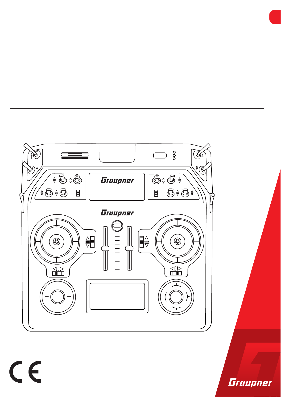
Fixed-wing models
The servos must be connected to the receiver in the indicated
sequence. Not assigned outputs remain free. It is possible to change
the settings in the line "Receiver outputs" in the "Model basic setting" menu.
Fixed-wing models with and without a motor with up to 4 ailerons
and up to 4 flaps and tail type "normal" or "2 elevator servos"
free or FLAP2 right or special function
free or FLAP2 left or special function
free or 2nd elevator or special function
free or AILERON2 right or special function
receiver power supply
FLAP right or free or special function
FLAP of FLAP left
AILERON right or special function
rudder
elevator or elevator1
AILERON or AILERON left
Airbrake or engine servo or electric drive controller
receiver power supply
free or AILERON2 left or special function
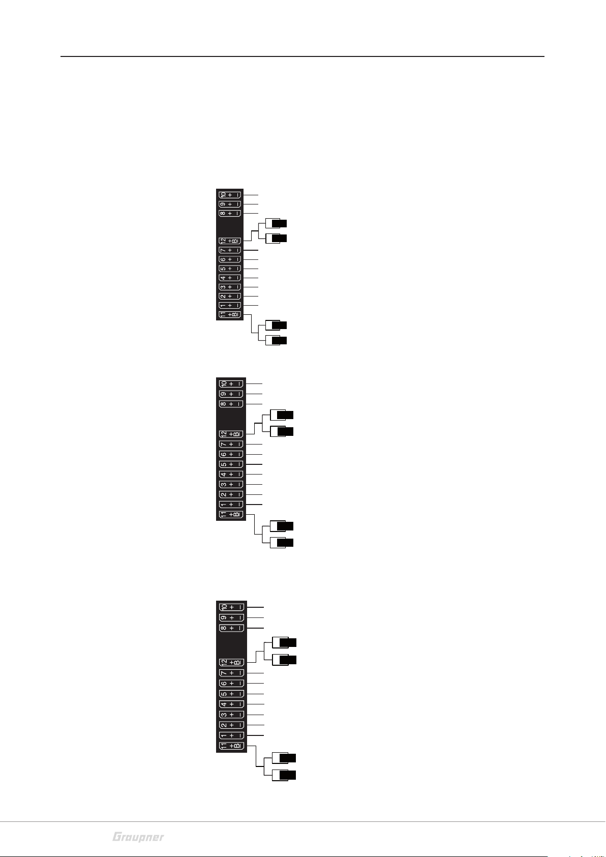
Tail type "V tail
free or FLAP2 right or special function
free or FLAP2 left or special function
free or special fucntion
free or AILE2 right or special function
receiver power supply
flap right or free or special function
flap or flap left
aileron right or special function
elevator/rudder right
elevator/rudder left
aileron or aileron left
airbrake or engine servo or drive controller
receiver power supply
free or AILE2 left or special function
Delta/flying wing models with and without a motor with up to 4
ailerons/elevators and 4 flap/elevator servos
free or special function or flap 2 / elev right
free or special function or flap 2 / elev left
free or special function
free or special function
receiver power supply
free or flap / elev right
fre or flap / elev left
free or special function
free or rudder
aile/elev right
aile/elev left
Airbrake or motor servo
or ESC for electric models
receiver power supply
10 / 80
free or special function
33028_mc_28_Teil2_jh
Page 11
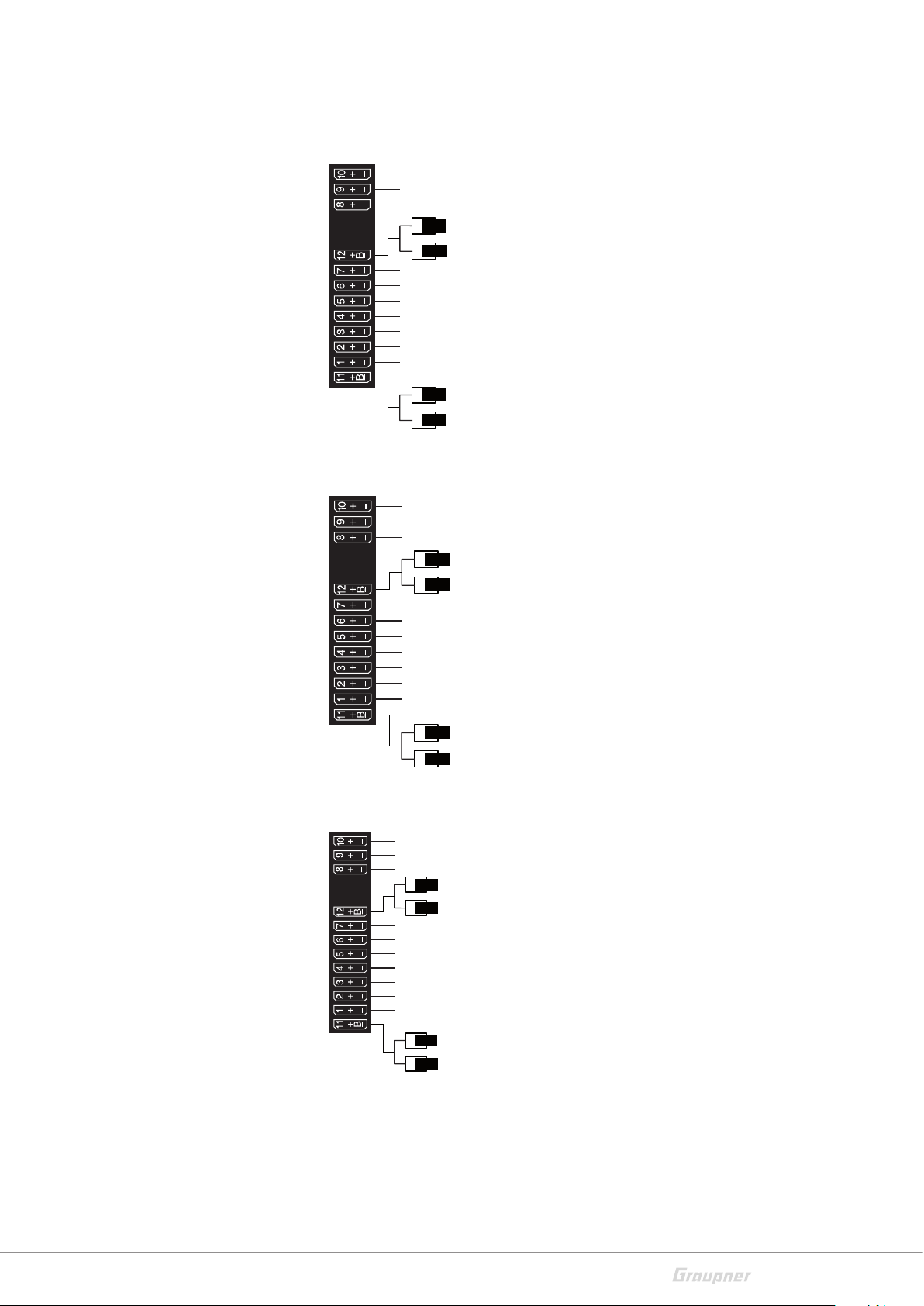
Helicopter models
engine servo or speed controller (forward/backward)
Receiver assignment for helicopter models with 1 to 3 swashplate
servos
free or special function
free or special function
free or governor or special function
free or special function
receiver power supply
gyro suppression
throttle servo or motor controller
free or special function
tail servo (gyro-system)
Nick-1-servo
Roll-1-servo
Pitch- or Roll-2 or Nick-2-servo
receiver power supply
free or special function
Receiver assignment for helicopter models with 4 swashplate servos
free or special function
free or special function
free or governor or special function
free or special function
receiver power supply
gyro suppression
throttle servo or motor controller
Nick-2-servo
Tail-servo (gyro-system)
Nick-1-servo
Roll-1-servo
Roll-2-servo
Vehicles, boats
receiver power supply
free or special function
free or special function
free or special function
free or special function
free or special function
receiver power supply
free or special function
free or special function
free or special function
free or special function
free or special function
steering (left/right function)
receiver power supply
free or special function
33028_mc_28_Teil2_jh
11 / 80
Page 12
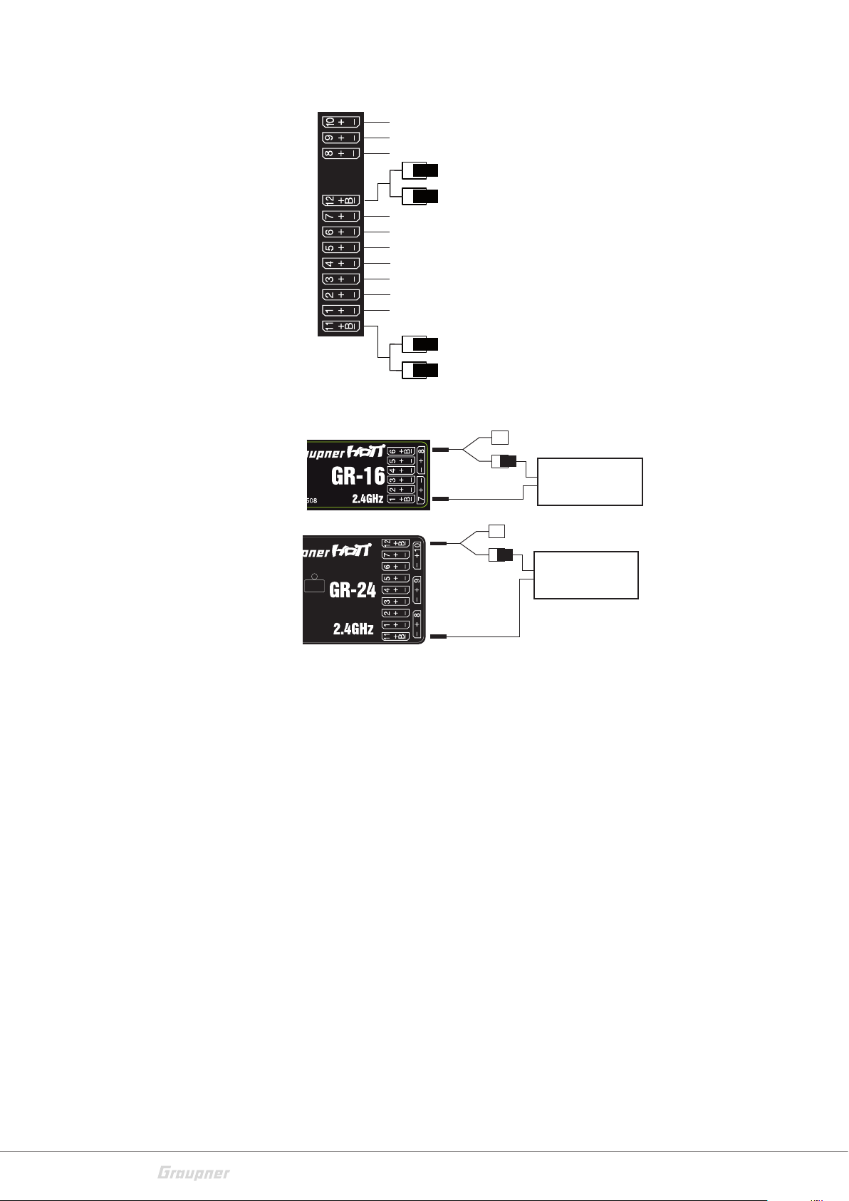
Copter
free or special function
Receiver power supply
free or special function
free or special function
free or special function
free or special function
receiver power supply
free or special function
free or special function
free or special function
Yaw
Nick
Roll
Motor/Pitch (up/down)
receiver power supply
special function
V-cable
No. 3936.11
V-cable
No. 3936.11
PRX stabilized
receiver power
supply No. 4136
special function
PRX stabilized
receiver power supply
No. 4136
12 / 80
33028_mc_28_Teil2_jh
Page 13
Symbols explication
!
Menus description
Always observe the information indicated by this warning sign. Par-
ticularly those which are additionally marked with the
WARNING. The signal word WARNING indicates the poten-
or
tial for serious injury, the signal word
ity of lighter injuries.
The signal word
Note indicates potential malfunctions.
CAUTION indicates possibil-
CAUTION
Attention indicates potential damages to objects.
The menus are described in the same sequence as they appear in
the lower display. Tap on the SET button in the base display to switch
in the multifunction menu.
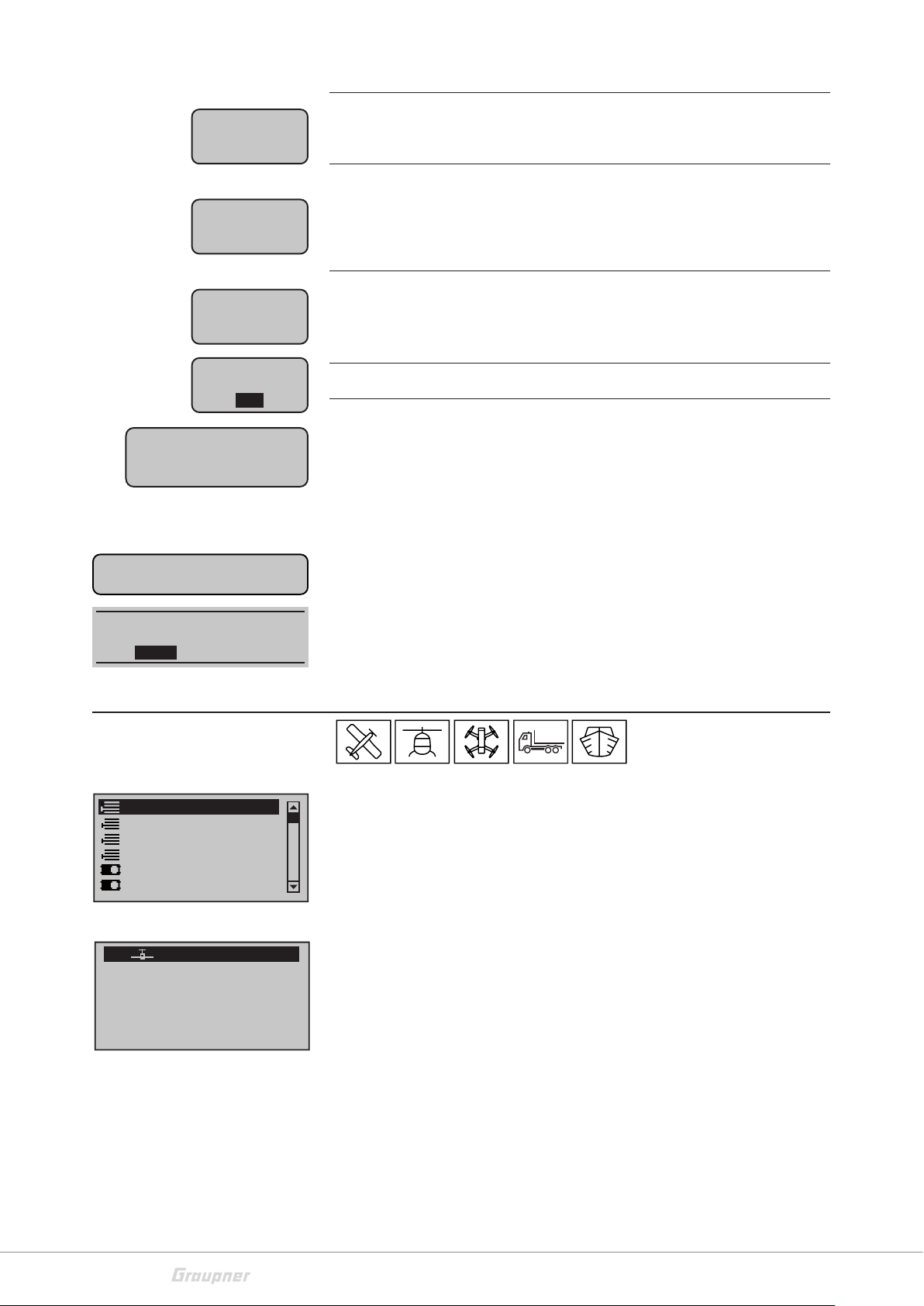
The chapters of the manual are marked with model type symbols.
The symbols are exactly the same used in the transmitter. It shows
you which paragraph is related to your model type. Thus makes it
easier to find which paragraph is required for each model programming.
Meaning of the warnings
Battery
needs
charging !!
BIND?
OK
Warning!
Switch OFF the receiver
first!
CAN‘T
RECEIVE
DATA
OK
Please select
RF on/off?
ON
OFF
Transmitter input voltage too low
"Bind?"
No receiver is bound to the actually active model memory. By
shortly tapping the SET button you can accede the related option.
You want to perform a model change in the "
but the receiver of the actually active model is however still
switched on.
No bound receiver in range.
Should the RF transmission be switched "ON" or "OFF"?
It appears only after switching the transmitter on with already
bound receiver in active model memory.
Model select" menu
33028_mc_28_Teil2_jh
Switch
RF module
OFF
OK
Request to switch the RF transmission off
13 / 80
Page 14
Fail-Safe
setup
t.b.d.
Fail Safe setting not performed yet
Thr
too
high!
No
pupil
signal
insert
SD card
OK
Power-on warning
is active!!!
actually not possible
voltage too low
Please select
Trainer connection?
ON OFF
Throttle or pitch control stick position or throttle limit for helicopters too high
Connection between teacher and pupil transmitter disturbed
No SD or SDHC memory card in the card slot or card not readable.
Within the time set in the line "Switch-on warning" of the "general
settings"
menu the transmitter has not been used. In the display it
appears the warning and the WARNING LED on the right side
of the On/Off switch blinks and an acoustic warning alarm is emitted.
If the transmitter is still not being used it will autonomously switch
off after about three minutes.
In case of too low battery voltage a model change is not possible for
safety reasons. In the display appears a related message:
Should the "Wireless Teacher/pupil connection" used before the last
switch off of the transmitter be continued (CONTINUE) or interrupted (INTERRUPT)?
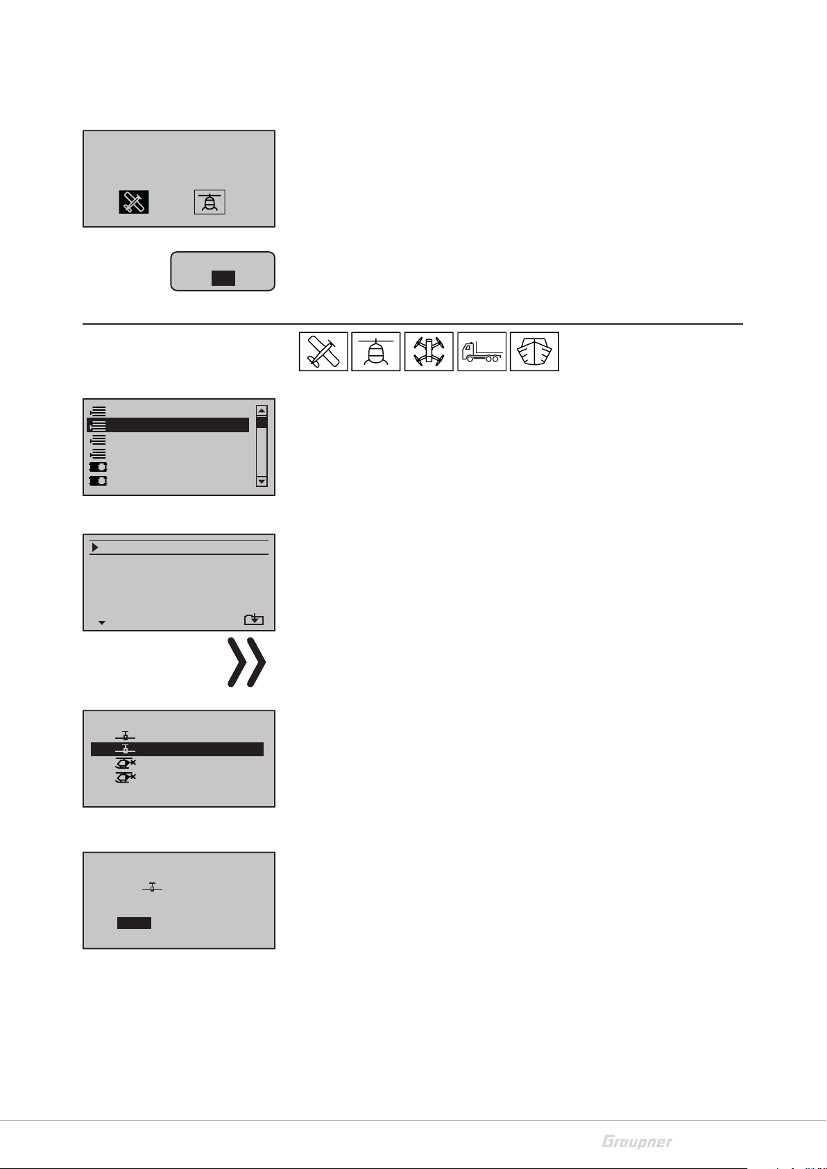
Model selection
Model select
Copy / Erase
Suppress menus
Suppress models
Base setup model
Model type
01
02
03
04
05
06
free
free
free
free
free
Tap on the SET button to access the menu. Now you can see the list
of the available model memories. Selection of the desired model
memory through the or buttons of the left or right touch-pad.
Then tap on the SET button.
Create a new model memory, select an empty model memory:
You will be requested to select the desired model type among the
M
R12
five available model types.
Select through the or buttons the related symbol and then tap
on the SET button. In this way the selected model memory will be
installed with the selected model type.
14 / 80
33028_mc_28_Teil2_jh
Page 15
With this selection model specific settings will be available in the
menus. Now you can program your model in this model memory.
Select model type
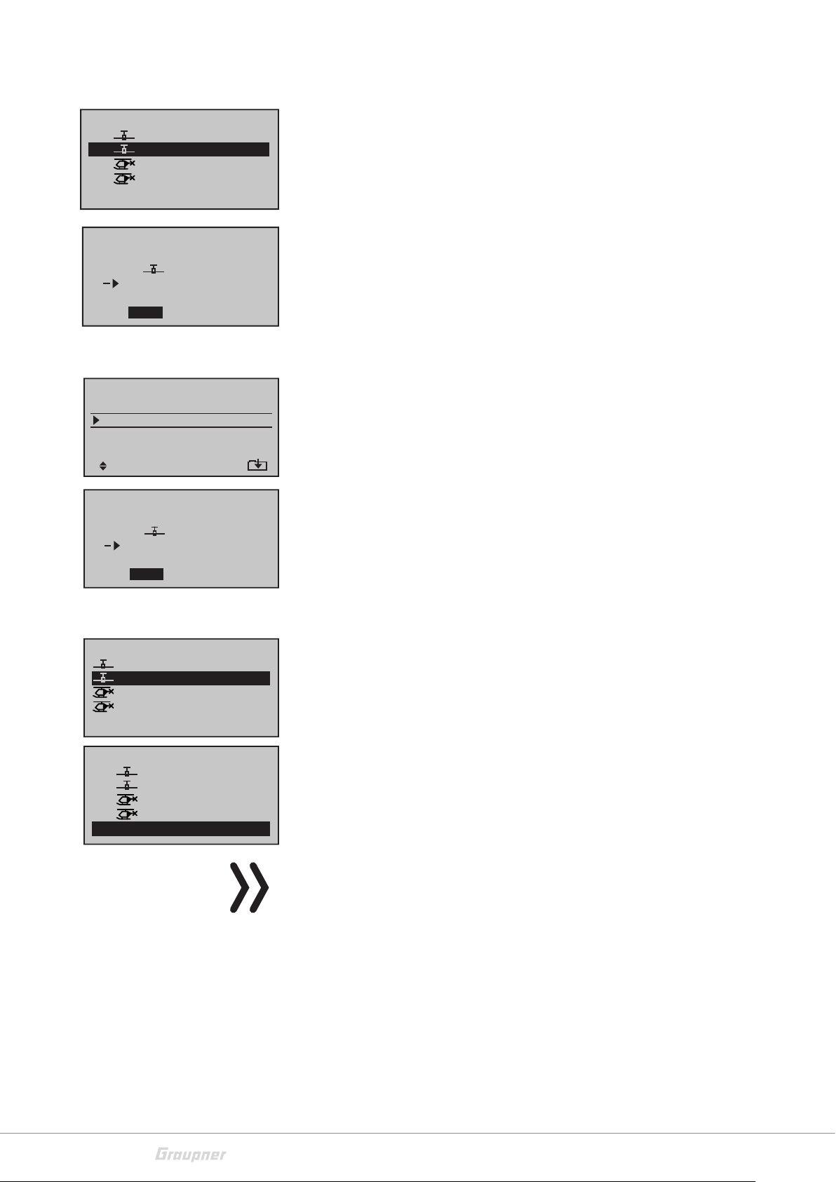
Copy/Delete
Model select
Copy / Erase
Suppress menus
Suppress models
Base setup model
Model type
Erase model
Copy model–>model
Export to SD
Import from SD
Copy phase
BIND?
OK
=>
=>
=>
=>
=>
=>
=>
After the initialization of the selected model memory with the
desired model type the display changes to the base display of the
new assigned model memory. At the same time it will appear for
some seconds the warning message that there is no connection with
a receiver. Tapping on the SET button you will directly enter the "Base
menu". Here you are directly in the line for binding. For the binding
process, please read the description in the "Model base setting"
menu. Tap on the ESC button to procede without binding.
Tap on the SET button to access the menu. Now you can see the list
of the available functions. On the right side of the display there is a
scrollbar. That indicates you that there are other menu points other
than the actually visible ones. Scroll with the selection buttons up or
down.
Delete model
Select the "delete model" point an confirm through the SET button.
On the lower left side you can see an arrow facing down. That indicates you that there are other menu points other than the actually
visible ones. Scroll with the selection buttons up or down.
Model to be erased:
01
02
03
04
05
GRAUBELE
ULTIMATE
STARLET
BELL47G
frei
Model really
01
to be erased ?
NO
GRAUBELE
YES
Note
This deletion cannot be restored. All of the data in the selected
model memory are completely deleted.
If the actually active model memory is deleted, soon after the dele-
M
R12
G
R12
R12
M
M
–––
tion process it must be defined a favorite model type. If an inactive
model memory is deleted, soon after the model selection appears
"àààfreeààà".
Use the selection buttons of the left or right touch-pad to select
the model to delete.
It appears a safety query. The deletion process will be performed
only if you move to YES and tap on the SET button. Selecting NO and
tapping on SET button interrupts the deletion process.
33028_mc_28_Teil2_jh
15 / 80
Page 16
Copy from model:
01
02
03
04
05
GRAUBELE
ULTIMATE
STARLET
BELL47G
frei
Copy Mod¢Mod
Select the point "Copy Mod¢Mod" and confirm through the SET
R12
M
R12
G
R12
M
–––
M
button.
Through the ESC button you can always interrupt the process.
• Select the model to copy and confirm the selection through the
SET button.
Model
01
SD-CARD
export ?
NO
ULTIMATE
YES
Export to SD card
Erase model
Copy model–>model
Export to SD
Import from SD
Copy phase
Model
01
SD-CARD
export ?
NO
ULTIMATE
YES
Import from SD
Import from SD-CARD:
ALPINA
EXTRA
COBRA
BELL47G
05
Import to model:
01
02
03
04
05
frei
GRAUBELE
ULTIMATE
STARLET
BELL47G
free
16/08/10
16/08/11
16/08/12
16/08/13
• Select the target memory and confirm through the SET button.
It appears a safety query. If you change to YES and press the SET button, the copy process will be performed. The copy process is interrupted if you select NO.
=>
=>
=>
=>
=>
=>
=>
Select the "Export to SD" point an confirm through the SET button.
Through the ESC button you can always interrupt the process.
Select the model to export and confirm the selection through the
SET button.
It appears a safety query. If you change to YES and press the SET button, the export process will be performed. The process is interrupted
if you select NO.
Select the "Import from SD" point an confirm through the SET button.
Through the ESC button you can always interrupt the process.
• Select the model to export from the SD card and confirm through
the SET button.
R12
M
G
R12
R12
M
–––
M
• Select the target memory and confirm through the SET button.
It appears a safety query. If you change to YES and press the SET button, the import process will be performed. The import process is
interrupted if you select NO.
16 / 80
Note
If the imported model memory has been created in the transmitter
and is imported to the same model memory then the receiver connection remains. If the model memory is imported in another transmitter, then the receiver must be bound again.
33028_mc_28_Teil2_jh
Page 17
Erase model
Copy model–>model
Export to SD
Import from SD
Copy phase
=>
=>
=>
=>
=>
=>
=>
Copy phase
Select the "Copy phase" point an confirm through the SET button.
Through the ESC button you can always interrupt the process.
• Select the phase to copy and confirm the selection through the
SET button.
Copy from phase:
1
3
5
7
Copy to phase:
1
3
5
7
Export to SD
Import from SD
Copy phase
Store changes
undo changes
Export to SD
Import from SD
Copy phase
Store changes
undo changes
2
4
6
2
4
6
=>
=>
=>
=>
=>
=>
=>
=>
=>
=>
=>
=>
=>
=>
=>
=>
=>
=>
• Select the target phase and confirm the selection through the
SET button.
A safety query appears. If you change to YES and press the SET button, the copy process will be performed. The copy process is interrupted if you select NO.
Permanently save changes / undo changes
If you perform a model change or if you switch the transmitter off
the last stand of the programming of the model is saved in the model
memory. With the "Permanently save changes / undo changes"
function the change will be manually edited during the use.
Through the "Permanently save changes / undo changes" menu
point you can immediately save permanently the edited programming in the model memory.
Through the "Permanently save changes / undo changes" menu
point you can undo programming performed during the use. In this
way you can restore the last performed programming. You can
choose since when the undo action should start, between the last
switch-off or the last manual saving.
It appears a safety query. If you change to YES and press the SET button, the related process will be performed. The process is interrupted if you select NO.
33028_mc_28_Teil2_jh
17 / 80
Page 18
Suppress menus
Model select
Copy / Erase
Suppress menus
Suppress models
Base setup model
Model type
Model select
Copy / Erase
Suppress models
Base setup model
Model type
Suppress : SET
Suppress models
Model select
Copy / Erase
Suppress menus
Suppress models
Base setup model
Model type
In this menu you can hide menu points from the menu function list.
The hiding is related to the model memory.
Select the menu point to hide or to show and switch the status
through the SET button. The crossed-out menu points are then no
longer displayed in the multifunction list.
The menu points are not deactivated, programmed functions in the
hidden menus remain active.
In this menu you can hide model memories from the model selection list.
Select the model memory to hide or to display, tap on the SET button to switch the status. The crossed-out model memories are then
no longer displayed in the model selection list.
R12
SET
M
G
R12
M
R12
–––
M
01
02
03
04
05
Suppress :
GRAUBELE
ULTIMATE
STARLET
BELL47G
free
Model basic settings
Suppress models
Base setup model
Model type
Servo adjustment
Stick mode
Control adjust
Base setup model
Mod. Name
Stick mode
HoTT
Module
Rcv Ch Map n/a
!"#$%&’()�+,–./0123
456789:;
FGHIJKLMNOPQRSTUVWX
YZ[¥]^_`abcdefghijk
bind
R08
BD1
?@ AB CDE
BD2
1
n/a
The model memories will not be deactivated, the programmed
options will be retained.
In this menu you will set the base setting for the actual model memory.
Model name
You can insert a maximum of nine characters for a model name of
the active model memory.
Through the left and right selection buttons you can move up or
down to the next place. Through the SET button you confirm the
selection and move to the next place. You can insert an empty space
if you tap at the same time on the up and dow or left and right buttons.
Through the ESC button you can leave the menu.
Mod Name
18 / 80
GRAUB
33028_mc_28_Teil2_jh
Page 19
Control mode
Base setup model
Mod. Name
Stick mode
Module
Rcv Ch Map n/a
GRAUBELE
HoTT
bind
R08
SEL
1
n/a
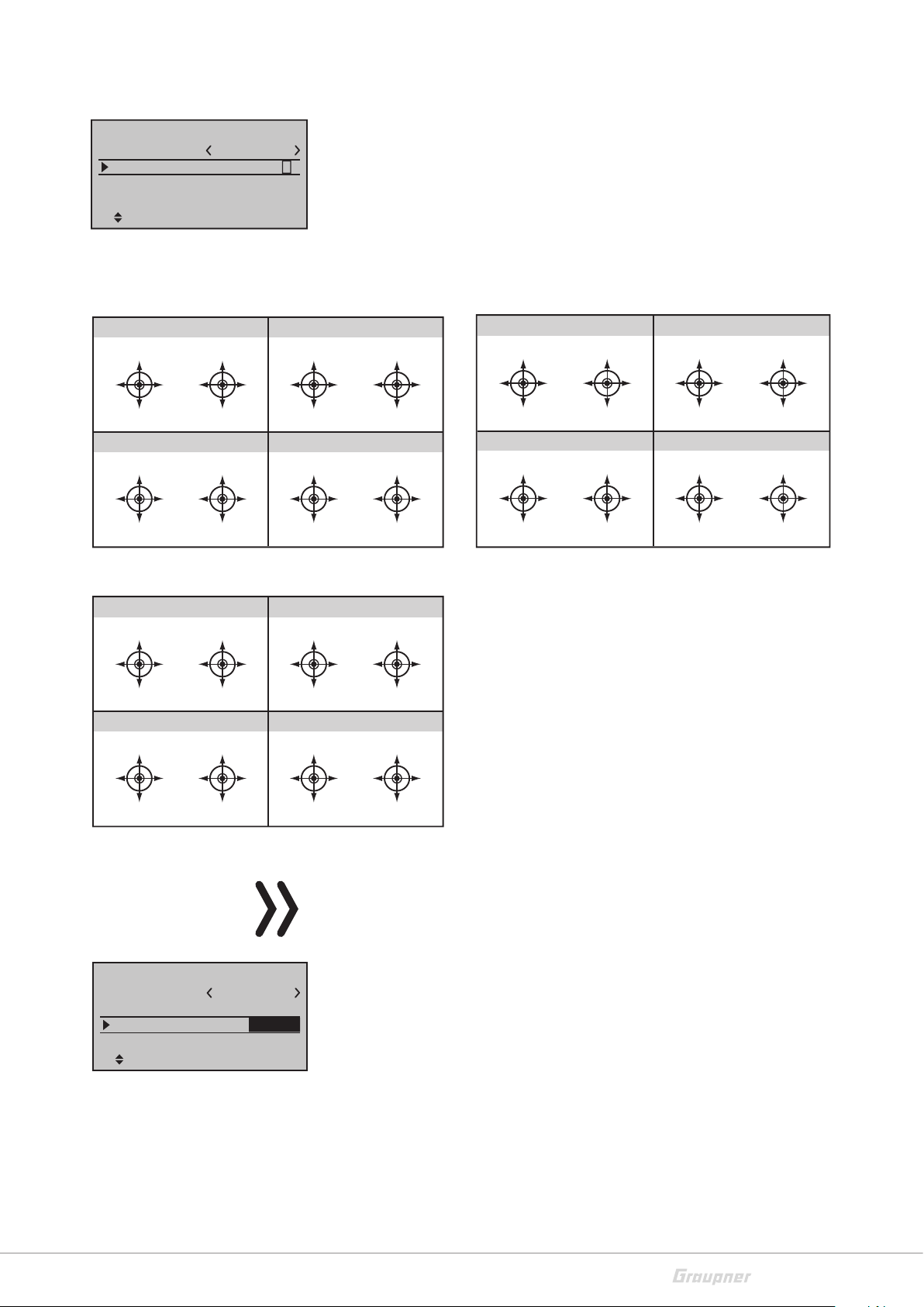
In this function you can choose a control mode which will be used
for this model memory. In this way it will be determined which control movement of the related control stick will we associated to
which channel. Tap n the SET button, set the desired mode through
the selection buttons. In the "receiver assignation" section you can
see where each servo should be connected.
Fixed-wing model
MODE 1 (Throttle right)
Elevator
Rudder
Elevator
Full throttle
Rudder
Querruder
Motor idle
MODE 3 (Throttle right)
Elevator
Aileron
Elevator
Full throttle
Aileron
Rudder
Motor idle
Car / boat
MODE 1 (for/backward right)
forward/backward
left
MODE 3 (for/backward right)
right
forward/backward
forward/backward
left
MODE 2 (Throttle left)
Full throttle
Querruder
Rudder
Motor idle
Rudder
MODE 4 (Throttle left)
Full throttle
Rudder
Aileron
Motor idle
Aileron
MODE 2 (for/backward left)
forward/backward
left
forward/backward
right
MODE 4 (for/backward left)
forward/backward
right
Elevator
Aileron
Elevator
Elevator
Rudder
Elevator
left
Aileron
Rudder
right
Helicopter model / Copter model
MODE 1 (Throttle right)
Nick
Tail rotor
Nick
Tail rotor
Motor / Pitch
Roll
Motor / Pitch
MODE 3 (Throttle right)
Nick
Roll
Nick
Motor / Pitch
Roll
Tail rotor
Motor / Pitch
Roll
Tail rotor
MODE 2 (Throttle left)
Motor / Pitch
Tail rotor
Motor / Pitch
MODE 4 (Throttle left)
Motor / Pitch
Roll
Motor / Pitch
Tail rotor
Roll
Nick
Roll
Nick
Nick
Tail rotor
Nick
Roll
Tail rotor
Binding type
Base setup model
Mod. Name
Control mode
Binding type
Module
HoTT
forward/backward
GRAUBELE
n/a
forward/backward
1
Model
n/a
SEL
Note
This menu line is only visible until no receiver is bound to the active
model memory.
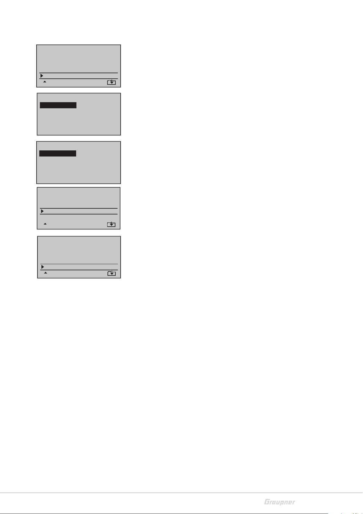
This option must be selected before the binding of a receiver. You
can select between "Global" and "Model", which means:
"Global": All bound receivers react to the signals of each model
memory of the transmitter. For safety reasons it is then only possible
to change model memory only after having switched the receiver off.
"Model": Bound receivers react only to the signals of the assigned
model memory. An accidental use thorough a non specifically
assigned model memory is not possible.
33028_mc_28_Teil2_jh
19 / 80
Page 20
01
02
03
04
05
06
GRAUBELE
ULTIMATE
STARLET
BELL47G
free
free
Module
Base setup model
Mod. name
Stick mode
Module
Rcv Ch Map R12
HoTT
M
R12
G
R12
R12
M
M
bind
BD1
–––
n/a
n/a
BD2
GRAUBELE
The binding type is indicated in the model memory list near the
model memory name:
"G" means global binding
"M" means model memory specific binding
Through the left and right selection buttons you can select the fields
in the lines. In the first "HoTT" field you have the following selection
1
possibilities:
HoTT - the integrated HoTT module will be used for the signal trans-
mission.
The following settings (EXT. and SP.) are included for eventual external RF modules of other manufacturers and they do not work with
HoTT receivers.
Base setup model
Mod. name
Stick mode
Module
EXT.PPM sig. normal
Base setup model
Mod. name
Stick mode
Module
SP channel 6
GRAUBELE
EXT.
SEL
GRAUBELE
S P.
Mod
PPM10
BIND1
BD
EXT. - the signal transmission is emitted through the DSC port to an
optional external RF module. Here is set the value PPM 10 (max. 10
1
control channels). The "Range test" and "Receiver outputs" functions are not available. Underneath appears a new line. Here you can
set if the PPM signal has to be emitted normally or inverted.
SP. - The signal transmission will be emitted as a special digital signal
through the DATA port. The binding will be performed through the
1
"BIND" field. Two new lines will appear underneath. In the first line
the number of the emitted channels
(6 or 8) will be set. In the second line you can set if the signal has to
be emitted normally or inverted. The "Range test" and "Receiver
outputs" functions are not available.
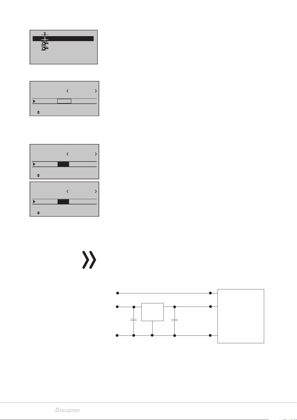
If the external RF module has to be powered with the current coming from the DATA port, then pay attention to what follows:
Note
The output tension of the DATA port of about 5 V must be reduced
through a stabilized step-down module to 3 / 3,3 V.
Pay attention to the switch scheme:
20 / 80
DATA S
Vcc IN = 5 V
DATA +
22µF/6.3 V
DATA -
Low Drop
Voltage
Regulator
GND
Vcc OUT = 3 ... 3.3 V
22µF/6.3 V
125000 baud signal
Vcc
SP.-MODULE
with
digital input signal
GND
33028_mc_28_Teil2_jh
Page 21
Receiver binding
Base setup model
Mod. name
Stick mode
Module
Rcv Ch Map
HoTT
GRAUBELE
n/a
n/a
n/a
n/a
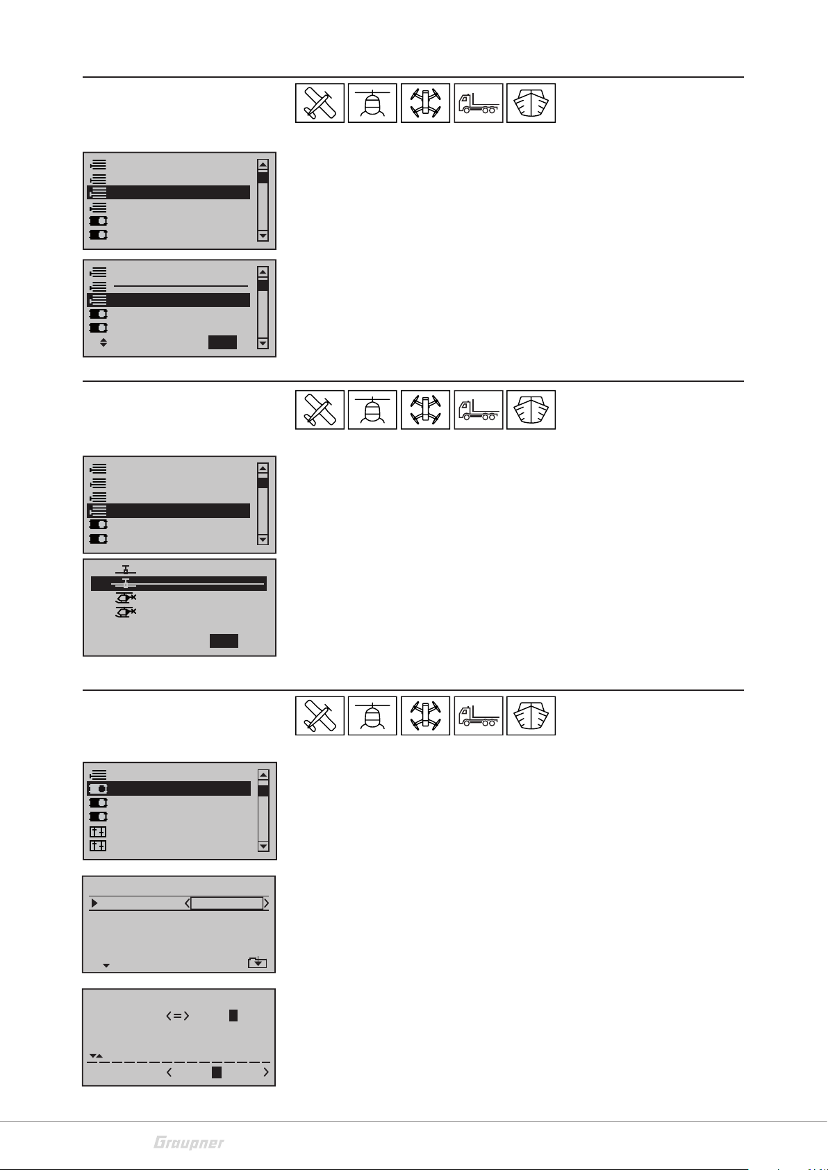
You can bind two receivers to the transmitter. The two bound receivers can be also managed in this option. You can split the control
channels of the receivers in the "Receiver output" as you prefer.
Binding process
Move to the "n/v" field near the "HoTT" field through the selection
buttons. Set your HoTT receivers in the binding mode. The binding
1
method is different for the different types of receiver, see the following table.
1. Set the receiver in the binding mode
Base setup model
Mod. name
Stick mode
Module
Rcv Ch Map R12
GRAUBELE
HoTT
bind
BD1
1
n/a
n/a
BD2
1st binding
Push and hold the binding button
method
Receiver type GR-12
green LED on
= bound
2nd binding
method
Push and hold the button until the LED blinks
red/green
GR-12L
red LED off =
bound
GR-18/24
green LED on
= bound
Receiver type GR-16 / 24 / 32 - green LED on = bound
3rd binding
method
No binding button, the receiver enters automatically the binding mode after switching on
Receiver type Gr-10C, GR-12 SC / SH
red LED off = bound
2. Tap now on the SET button, a "BIND" info window will appear.
If the binding process has been successful in the left field it appears
now "bound". In the line "Receiver output" appears now under the
"bound" field the identification of the receiver (e.g. E12 = GR-24). It
also appears BD1 and BD2 in the lowest line of the display. The meaning of the message will be cleared in the "Telemetry menu" section.
Note
33028_mc_28_Teil2_jh
If the binding process was not successful, verify the following conditions:
Is the distance between transmitter and receiver at least 50 cm?
Is the power source of the receiver OK?
Is the polarity of the power supply correct?
Was the binding button correctly pushed?
If you want to bind a second receiver, then proceed as described
before. Move therefore first to the right "n/v" field.
21 / 80
Page 22
Receiver output
Base setup model
Mod. name
Stick mode
Module
Rcv Ch Map R12
HoTT
GRAUBELE
bind
bind
R08
SET
SET
This function (Channel Mapping) is available as soon as in the line
"Module" is bound at least one receiver. Here you can split the con-
1
trol channels of the transmitter to the bound receivers. You can also
select freely the channel order within the receiver. In this way the
control channels coming from the transmitter will be assigned to a
free selectable output of the receiver.
Receiver CH – BIND1
In Ch 1
In Ch 2
In Ch 3
In Ch 4 Out Ch 4
Out Ch 1
Out Ch 2
Out Ch 3
RF module
Base setup model
Stick mode
Module
Rcv Ch Map
RF transmit
HoTT
bind
R12
Range test
Base setup model
Module
Rcv Ch Map
RF transmit ON
RF Range Test 99sec
HoTT
bind
R12
1
bind
R08
ON
SEL
bind
R08
SEL
Use the selection buttons to move to the receiver field that you want
to edit. Select the input that you want to assign to another output.
Tap on the SET button. Set the desired channel. Confirm the selection by pushing the SET button.
In this menu line the RF module of the transmitter is switched manually on and off. This line is only available if a receiver is bound.
The integrated range test reduces the transmitter output so that you
can perform a function test at a limited distance.
Perform the range test before each operation and simulate all servo
movements which are part of the operation. In order to guarantee a
safe model operation, the range must always be at least 50 m on the
ground.
Place the model on a flat surface (cement, mowed lawn or ground)
so that the receiver antennas are at least 15 cm above the ground.
If necessary, place a support underneath the model during the test.
Hold the transmitter at hip level at a slight distance from your body.
Keep the surface of the patch antenna of the transmitter in direction
of the model.
Start the range test by pushing the SET button. The time display "99
sec" will start the countdown. You will hear two acoustic signals each
two seconds, in the last five seconds the acoustic signals will be 3
each second.
During this time, move away from the model, and also move
the transmitter's control sticks. Let the control movements be
observed by a second person.
If within a distance of about 50 m there is no interference in the control movements of the model, then the range test can be considered
as successful. After the end of the 99 seconds
the transmitter switches again to full transmission power and the
green LED on the right of the main switch lights again permanently.
If the range test has not been successful, verify the following conditions:
22 / 80
33028_mc_28_Teil2_jh
Page 23
DSC port
Base setup model
Rcv Ch Map R12
RF transmit ON
RF Tange Test 99sec
DSC Output PPM10
R08
SEL
Is the power supply of the receiver OK?
Is the position of the receiver antennas correct?
Are there any interference from electronic component in the
model?
If you have verified these conditions and against it you coul not perform a successful range test, then please contact ou Customer Service (see section "Service Center").
This selection influences the number of control channels available at
the DSC port. The selection means:
PPM10 = Channel 1 - 5
PPM16 = Channel 1 - 8
PPM18 = Channel 1 - 9
PPM24 = Channel 1 - 12
Throttle Cut
Base setup model
RF transmit ON
RF Range Test 99sec
DSC Output PPM10
cut off +150%–100%
SEL
Move desired switch
to ON position
(ext. switch: SET)
STO
–––
This function is only available if in the "Model type" menu you have
set "forward" or "backward" in the Motor to CH1 option.
With this function the throttle channel (CH1) can be switched and
hold in a specific position (-100%) through a switch. In this position
it is then not possible that the motor starts accidentally, no matters
in which position the throttle stick is.
In the left column you can set the position in which the throttle channel (CH1) will be switched. In the third column you can set the switch
threshold. To do that you have to move the stick to the desired position and tap on the SET button. In this way the switch range will be
set.
In the right column you can assign the desired switch. Proceed as follows:
Tap on the SET button in the "Thr.cut" line.
Move the desired switch to the position in which the motor will
be switched off. Combinations with logical switches are also possible.
33028_mc_28_Teil2_jh
23 / 80
Page 24
Switch-on warning
Base setup model
RF transmit ON
RF Range Test
DSC Output PPM10
Power on warning
99sec
–––
With this option it is possible to program the query for the position
of a switch or control so that when the transmitter is switched on in
the base display a warning will appear.
To do that you have to assign in this line a switch, a control switch or
a logical switch.
Activate a warning:
Move desired switch
to ON position
(ext. switch: SET)
GRAUBELE
01
! Warning !
4.1V
0:01h
S
L
«normal »
K78
M
Auto trim
Base setup model
RF Range Test
DSC Output PPM10
Power on warning
Auto Trim
0:00.0
0:00.0
HoTT
4.8V
99sec
–––
8
Tap on the SET button in the "Switch-on warning" line.
Move the desired switch to the position that has to be verified.
Combinations with logical switches are also possible.
If the warning is active the blue LED
WARNING in the transmit-
ter blinks while the transmitter is switched on and the RF module
remains switched off. To deactivate the warning move the programmed switch in another position.
Deactivate the warning:
Tap on the SET button in the "Switch-on warning" line.
Tap on the Up and Down buttons of the right selection field.
In the selection field will be displayed three lines. No switch is
assigned any more.
With this function you can save the actually controlled position of a
model in the trim memory. The function acts on channel 2, 3 and 4
only. This function will be activated through a switch. Select the line
"Auto trim" and tap on the SET button. Move a switch in the desired
position. We recommend to select a momentary switch.
Timer auto reset
Base setup model
RF Range Test
DSC Output PPM10
Power on warning
Auto timer reset
99sec
–––
yes
Save the position in the trim memory step-by-step:
3. Move the model to the desired position through the control
sticks.
4. Actuate the assigned switch and move the control sticks back
to the neutral position.
5. After 1 sec. the position will be saved in the trim ( ± 30%).
Note
If the auto trim function is not required any more, then we suggest
to deactivate the switch assigned to the "Auto trim function".
Thereby you avoid an accidental error function.
In this line you can select:
"Yes" - all timers, excluded model timer and transmitter operating
timer, will be set back to zero when you switch the transmitter on.
"No" - all timers hold the stand from the last use of the transmitter.
The timer will however be reset when the transmitter is switched on.
24 / 80
33028_mc_28_Teil2_jh
Page 25

Model type
Suppress models
Base setup model
Model type
Servo adjustment
Stick mode.
Control adjust
In this menu you can adjust the settings for the actual model type.
Here you can select for example the tail and wing type or whether
the model has motor or not.
Model type
Motor at C1
Leitwerk
Querr./Wölb
Bremsoffs. Ein1+100%
None
normal
1QR
SEL
If in the model selection you have chosen copter, car or boat in this
menu will appear only the line "Motor at CH1". Here you have the
following selection possibilities:
"None"
You are using a model without drive. The warning "Throttle too
high!" is deactivated and the sub-menu "Brake settings" of the "Wing
mix" menu is available.
"Backward"
The idle position of the Throttle/Airbrakes control stick (CH1) is in
the backward position, in the pilot direction. The warning "Throttle
too high!" so as the "Throttle cut" option of the "Model base settings" menu are active.
"Forward"
The idle position of the Throttle/Airbrakes control stick (CH1) is in
the forward position, in the opposite direction of the pilot. The warning "Throttle too high!" and the "Throttle cut" option of the "Model
base settings" menu are active.
Note
The CH1 trim acts accordingly to your selection "normally" or only
"backward" or "forward", then through the entire control travel or
only in the related idle direction.
Please pay attention to the "Switch-off trim" function described in
the "Digital trim" section.
33028_mc_28_Teil2_jh
25 / 80
Page 26

Motor on CH1
Model type
Motor at C1
Tail type
Aile/flaps
Brake Off In1+100%
Tail
Model type
Motor at C1
Tail type
Aile/flaps
Brake Off In1+100%
None
Normal
1AIL
SEL
None
normal
1AIL
SEL
If you have selected airplane in the model selection, it will also
appear the line "Motor at CH1". The setting are also here as previously described.
Here you can select the tail type of your model to obtain the related
control signals at the receiver outputs (see "Receiver assignation"
menu).
"Normal"
The elevator and rudder are controlled each by only one servo.
"V tail"
The elevator and rudder are controlled by two separately-articulated
rudders arranged in a V-shape. The coupling function for the rudder
and elevator control is automatically transferred from the program.
The influence of the rudder on the elevator component can be set
in the "Dual Rate / Expo" menu. The servo travels can be adjusted
one to the other in the "Servo setting" menu. If the rudder travel has
to be differentiated, then you have to select here the tail type "normal" and the V tail has to be set alternatively in the "Cross mixer"
menu.
"Delta"
This option must be selected for delta wing models. In case of selection of "2 AILE" in the line "Ailerons/Flaps", see following, the aileron
and elevator control is actuated respectively by one servo each halfwing. In case of selection of "2/4AILE 2/4FLAP" the aileron and elevator control depends on the settings in the "Multi-flap menu" submenu of the "Wing mix" menu.
"2 ELE Sv 3+8"
This option is indicated for models with two elevator servos. When
the elevator control is actuated, the servo connected to the output
8 works in parallel with servo 3. The elevator trim acts on both servos.
Note
In case of "2ELE Sv 3+8", for safety reasons, there is no selection possibility for the input 8 in the "Control setting" menu. An already programmed control would be useless.
26 / 80
33028_mc_28_Teil2_jh
Page 27

Ailerons/Flaps
Model type
Motor at C1
Tail type
Aile/flaps
Brake Off In1+100%
None
normal
1AIL
SEL
In this line you can select the number of servos installed in the wings.
The following table shows the control channels to which the servos
must be connected.
Control surfaces
Occupied control channel
count
1AILE 2
1AILE 1FLAP 2 | 6
2AILE 2 + 5
2AILE 1FLAP 2 + 5 | 6
2AILE 2FLAP 2 + 5 | 6 + 7
2AILE 4FLAP 2 + 5 | 6 + 7 / 9 + 10
4AILE 2FLAP 2 + 5 / 11 + 12 | 6 + 7
4AILE 4FLAP 2 + 5 / 11 + 12 | 6 + 7 / 9 +
10
According to this scheme the related required mixers and their setting possibilities are activated in the "Wing mix" menu.
Brake offset
Model type
Motor at C1
Tail type
Aile/flaps
Brake Off In1+90%
Servo adjustment
None
normal
1AIL
SELSTO
In this line is set the offset point in which the control surfaces (AILE/
FLAP) are completely retracted or closed.
The function will be assigned to the related input in the right column.
Offset_point assignation:
Move the control element of the input CH1-control stick input 1,7,8
or 9 in the position where the control surfaces have to be retracted
or closed. Tap on the SET button to save the "Offset" point.
The flaps are extended for brake offset values with a "+" when
the corresponding control element is moved from front to rear
toward the pilot.
The flaps are extended for brake offset values with a "-" when the corresponding control element is moved from back to front away from
the pilot.
Suppress models
Base setup model
Model type
Servo adjustment
Stick mo de
Control adjust
33028_mc_28_Teil2_jh
In this menu the servo parameters are set for each servo: servo
direction, neutral point, servo travel and limits. Start the servo setting basically in the left column.
27 / 80
Page 28

Column 1
S
e
r
v
o
t
r
a
v
e
l
S1
S2
S3
S4
S5
Rev cent
0%
0%
0%
0%
0%
100%
100%
100%
100%
100%
100%
100%
100%
100%
100%
trv
+
In the first column are listed the control outputs.
The numbers for the servos refer to the servos connected to the corresponding receiver outputs providing that the transmitter and
receiver outputs have not been switched. A change in the control
mode therefore does not influence the numbering of the servos.
Column 2 "Rev"
With this option it is possible to adapt the servo direction to the specifics of each model.
Selection through the SET button and t u: "=>" normal, "<="
reverse
j
u
d
s
a
t
m
e
r
t
n
e
C
e
n
t
Column 3 "Cent"
You can slip the servo centre in a ±125 % area within the servo travel
of max. ±150 %. The servo is always adjusted directly independent
of all other trim and mix settings.
Column 4 "– Trv +"
In this column you can set the servo travel for both sides, together
or separated for each side. The setting range is 0 … 150% of the normal travel. The set values always refer to the settings in the column
"Centre".
Symmetrical travel setting:
Move the related control element (control stick, proportional control or switch) into a position in which both sides of the travel adjustment are surrounded by the marking frame.
Asymmetrical travel setting:
Move the related control element (control stick, proportional control or switch) into a position in which the single side of the travel
adjustment is surrounded by the marking frame.
Column 5 "Lim"
S1
S2
S3
S4
S5
Rev cent
0%
0%
0%
0%
0%
150%
150%
150%
150%
150%
150%
150%
150%
150%
150%
lim
+
In this column you can limit the servo travel. You can reach the column "- lim +", if you move the marking frame to the right over the
column "- Trv +" through the selection button .
Symmetrical or asymmetrical setting of the limit as explained in the
"– Trv +".
point
28 / 80
33028_mc_28_Teil2_jh
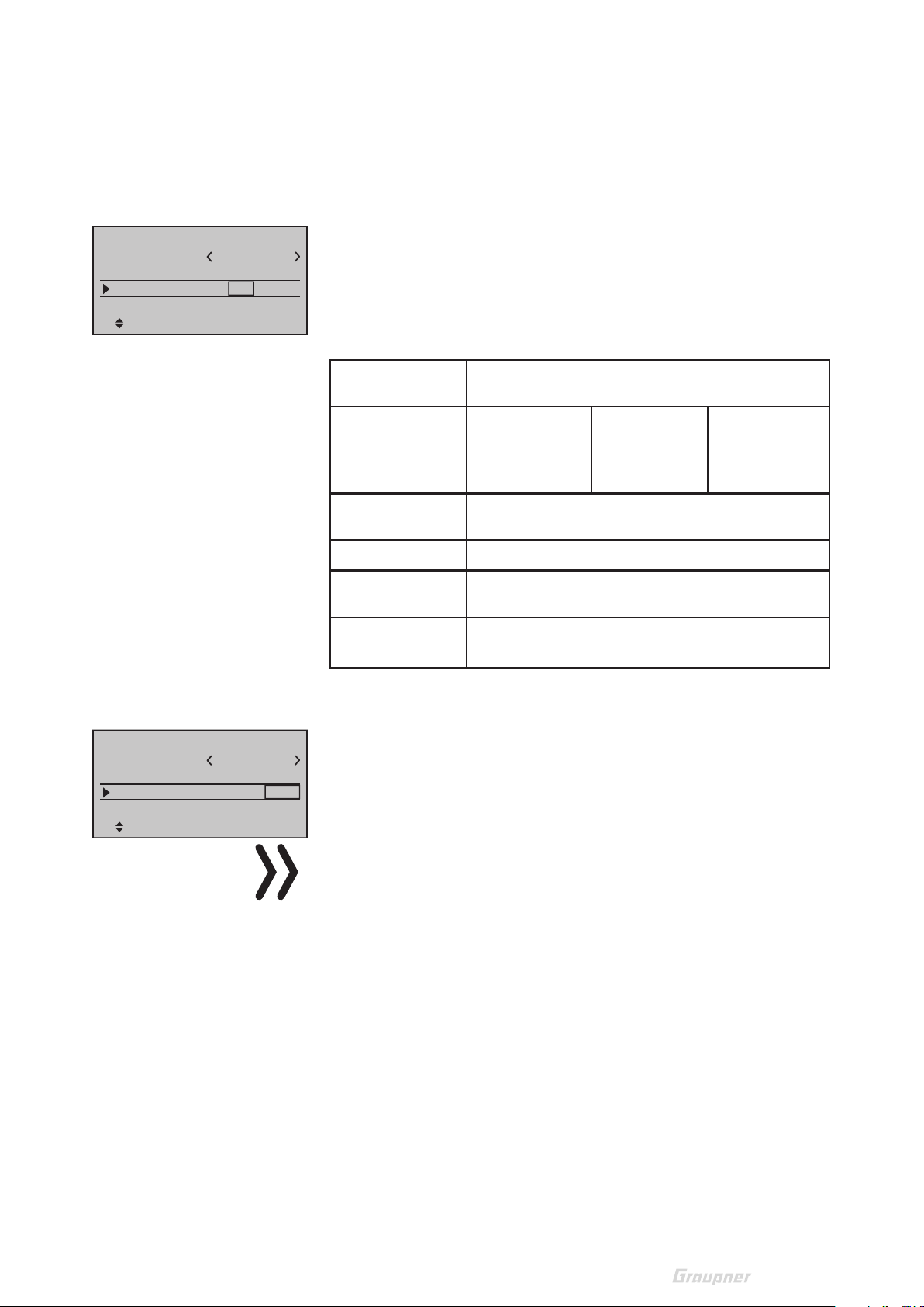
Page 29

Sticks setting
Servo adjustment
Stick mode
Control adjust
Dual Rate / Expo
Channel 1 curve
Switch display
Ch.1
Aile
Elev
Rudd
GL
PH
PH
PH
Tr
St
In this menu you can set the step value of the trim and the control
speed. This settings are valid for the channels one to four. The channels are listed with their function in the first column, according to
the chosen model type.
Column "Tr"
4
4
4
4
0.0s
0.0s
0.0s
0.0s
time
0.0s
0.0s
0.0s
0.0s
+
In this column you can choose if the function has to act globally (GL)
or according to the phase (PH). (Not for "CH1"). In the main display
the related setting will be displayed through a shadow on the trim
columns.
Shadow = global
No shadow = according to the phase
Column "St"
Here you can set the step "width" of the trim (0 to 10)
The setting acts always globally, max ±30% of the servo travel.
Column "- time +"
In this column "Time" it is possible to set the movement speed for
each movement direction of the control sticks 1 to 4 individually. The
setting acts always globally.
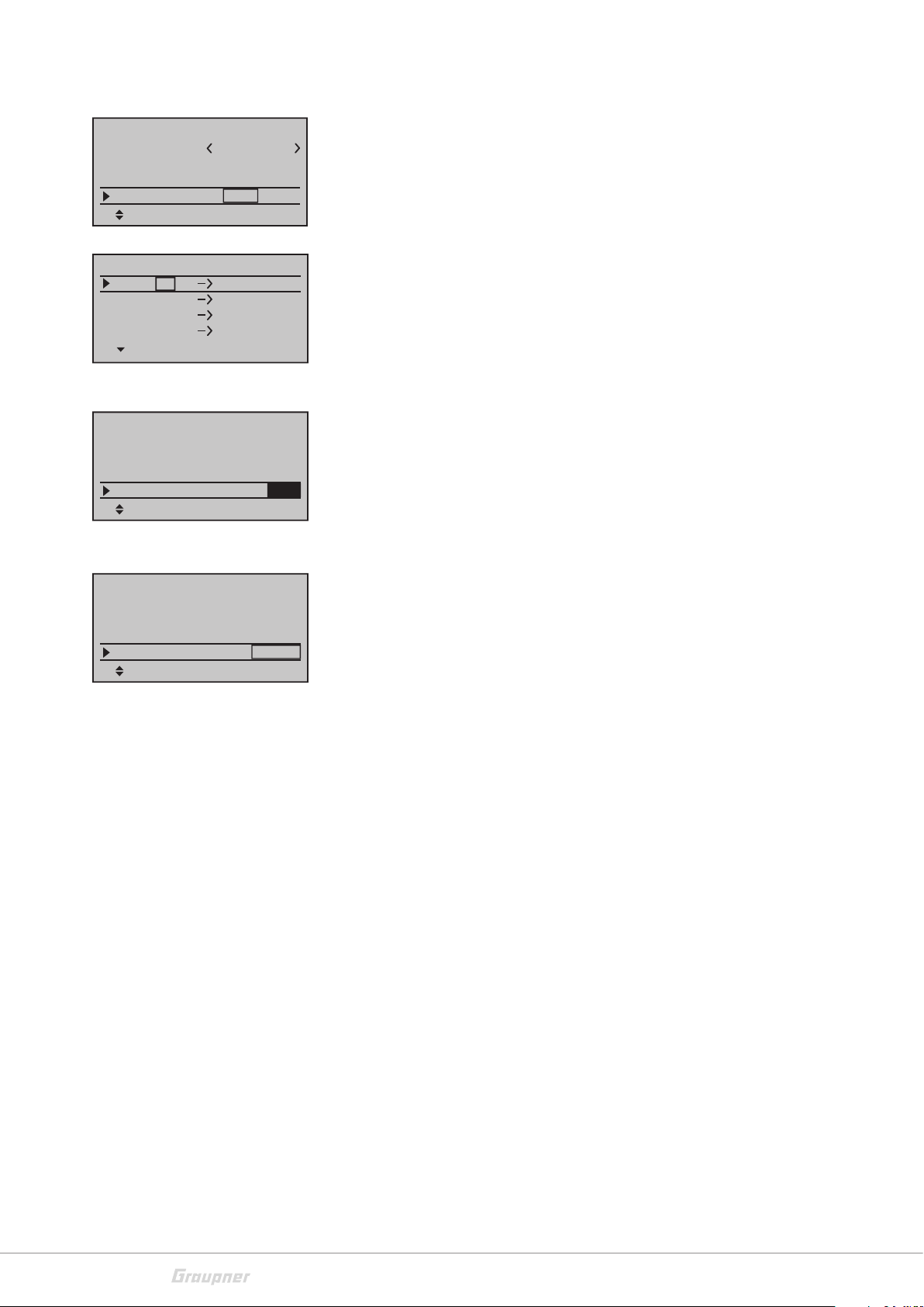
Controls setting
Servo adjustment
Stick mode
Control adjust
Dual Rate / Expo
Channel 1 curve
Switch display
GL
GL
GL
GL
typ
fr
fr
fr
fr
SEL
–––
–––
–––
–––
In5
In6
In7
In8
normal
0%
0%
0%
0%
offset
Symmetrical setting of time:
Move the related control stick into a position in which both sides of
the time adjustment are surrounded by the marking frame.
Asymmetrical setting of time:
Move the related control stick into a position in which each single
side of the time adjustment is surrounded by the marking frame.
In this menu it is possible to assign the control elements (controls)
of the transmitter to the channels. It is only possible for channels 5
to 16, because the channels one to four are preassigned to the control sticks.
The other channels will be visible if you scroll down with the selection buttons.
The transmitter is supplied with switches, buttons and rotary encoders that act separately on the channels.
If you scroll to the right with the selection buttons, other columns
will be visible.
33028_mc_28_Teil2_jh
29 / 80
Page 30

In5
In6
In7
In8
Normal
In5
In6
In7
In8
Normal
In5
E6
Move desired switch
E7
to ON position
E8
(ext. switch: SET)
Normal
fr
fr
fr
fr
SEL
fr
fr
fr
fr
SEL
fr
SD2
fr
fr
SEL
–––
–––
–––
–––
–––
–––
–––
–––
–––
–––
–––
–––
GL
GL
GL
GL
typ
GL
GL
Move desired
GL
control adj.
GL
typ
GL
GL
GL
GL
typ
0%
0%
0%
0%
offset
0%
0%
0%
0%
offset
0%
0%
0%
0%
offset
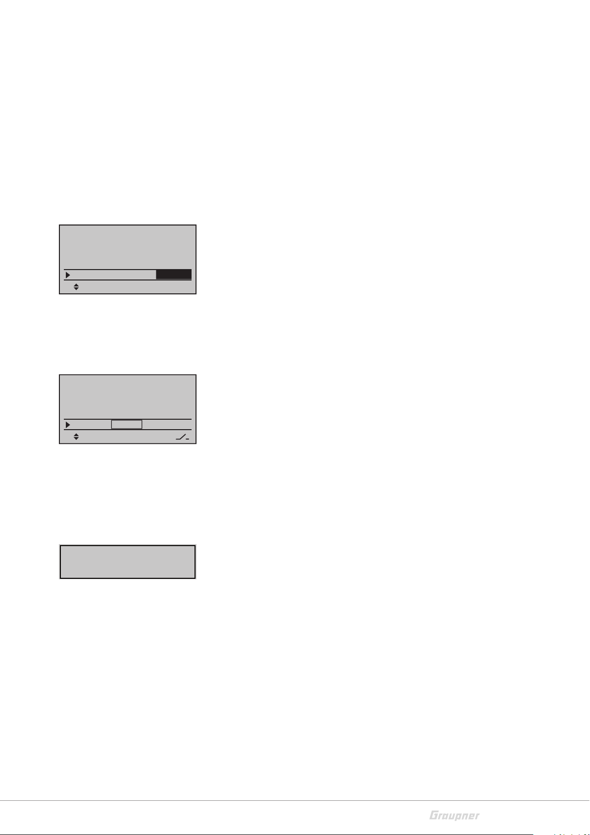
"Type"
In this column you can select if the control setting for this channel
has to act globally "G" or according to the phase "PH". If the control
has to be assigned specifically to the phase, the related phase must
be active. In the second line from the bottom of the display will be
shown the phase name.
"fr"
Here you can assign the desired proportional control. If no control is
assigned, it will be displayed "fr" (free). Here you can assign proportional controls only, no switch. Assign a control by pushing the SET
button and actuate the desired control. It will appear the abbreviation of the selected control.
"SEL "
Here you can assign the desired switch. If a proportional control is
already assigned, it will be deactivated and you will be able to assign
a second switch in the column. Ta again on SET, you can also assign
logical switches or normal switches.
Assign a switch by pushing the SET button and actuate the desired
switch. It will appear the abbreviation of the selected switch.
In5
In6
In7
In8
Normal
GL
GL
GL
GL
typ
Delete proportional control or switch:
• Use the SET button to select the desired field
• Tap on the selection buttons
t u or at the same time
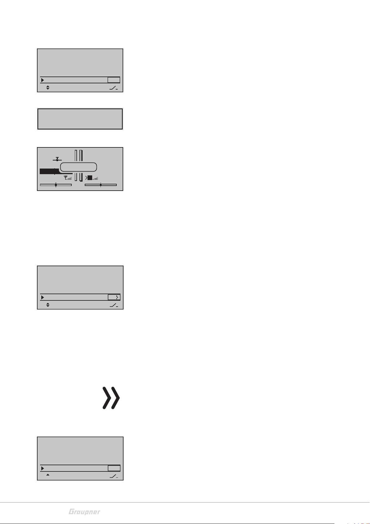
"Offset"
Here, move the center of the channel in a possible range from -125%
fr
–––
3
2
fr
–––
fr
–––
0%
0%
0%
0%
offset
to + 125%.
Symmetrical travel setting:
Move the related control element (control stick, proportional control or switch) into a position in which both sides of the travel adjustment are surrounded by the marking frame. Set with the SET button
and the selection buttons.
Asymmetrical travel setting:
Move the related control element (control stick, proportional control or switch) into a position in which the single side of the travel
adjustment is surrounded by the marking frame. Set with the SET
button and the selection buttons.
30 / 80
33028_mc_28_Teil2_jh
Page 31

In5
Servo travel
Servo travel
Control travel
Control travel
Dual Rate = 50%
Dual Rate = 20%
Servo travel
Control travel
Dual Rate = 20%
In6
In7
In8
Normal
In5
In6
In7
In8
Normal
+100%
+100%
+100%
+100%
– trv +
0.0s
0.0s
0.0s
0.0s
– time +
Dual Rate / Expo
+100%
+100%
+100%
+100%
0.0s
0.0s
0.0s
0.0s
"- Trv +"
You can reach the column by moving the marking frame with the
selection buttons over the "Offset" column to the right side.
In this column you can set the control travel for both sides, together
or separated for each side. The setting range is 0 … 150% of the normal control travel. The set values always refer to the settings in the
column "Centre". Perform a symmetrical or asymmetrical setting as
described in the "Offset" section.
"– Time +"
You can reach the column by moving the marking frame with the
selection buttons over the "Trv" column to the right side.
In this column, a time delay is set for the respective channel. The set
seconds indicate the time that elapses between the switching states.
If the encoder or switch is actuated, the switching process then runs
in the set time. Perform a symmetrical or asymmetrical setting as
described in the "Offset" section.
Servo adjustment
Stick mode
Control adjust
Dual Rate / Expo
Channel 1 curve
Switch display
–––
–––
–––
DUAL
Dual Rate = 100%
Servo travel
Control travel
Dual Rate = 50%
100%
100%
100%
SEL
Ail
Ele
Rud
In this menu you can set the options Dual Rate and Expo.
Dual Rate
With this option you can reduce the travel of each control function.
This reduction is activated through a switch or, if no switch is assigned,
it will be always active. The graphical representation to the right
shows the control path profile for the selected control function.
Setting the Dual Rate step-by-step:
• Select the line of the desired control function
• Assign the switch in the column
section "Control settings")
• Input the reduction value in the column SEL
Now you can use the selected switch to pass from reduced control
travel to full control travel.
If the function has to be assigned specifically to the phase, the
related phase must be active. In the second line from the bottom of
the display will be shown the phase name.
(process as described in the
Servo travel
33028_mc_28_Teil2_jh
Control travel
31 / 80
Page 32

Ail
Servoweg
Servoweg
Servoweg
Geberweg
Geberweg
Geberweg
Expo = +100%
Expo = +50%
Expo = –100%
Servoweg
Geberweg
Expo = –100%
Ele
Rud
Normal
3
–––
–––
EXPO
+33%
0%
0%
SEL
Expo
You can reach the column by moving the marking frame with the
selection buttons over the "SEL" column to the right side. It will
be shown "EXPO" instead of "DUAL".
With this function you can influence the travel of each control function. You can set an exponential curve. The graphical representation
to the right shows the control path profile for the selected control
function.
This function can also be activated through an assignable switch.
Setting the Expo step-by-step:
• Select the line of the desired control function
Expo = +50%
Servoweg
Geberweg
Throttle curve
• Assign the switch in the column
(process as described in the
section "Control settings")
• Input the Expo curve value in the column SEL
Now you can use the selected switch to pass from linear control
travel to exponential control travel.
Combining Dual Rate and Expo
If you have set Dual Rate and Expo so that they act at the same time,
the travels will overlap. You get a reduced, exponential course of the
control travel.
Asymmetrical setting of Dual Rate and/or Expo
If you wish to set an asymmetrical travel of the control function, you
can also assign a control switch (see the "Transmitter switch" menu).
As a result, the Dual Rate or Expo functions only affect one side of
the control travel.
32 / 80
Servo adjustment
Stick mode
Control adjust
Dual Rate / Expo
Channel 1 curve
Switch display
curve
Ch1
Curve
Input
Output
Point
Normal
off
?
0%
0%
0%
This menu allows you to change the control characteristics of the
control function 1. The control function acts directly on the servo
connected to control channel 1 or via several mixers to several servos. Settings in this menu affect the throttle / brake control function
for an airplane model and the throttle / pitch function for a helicopter model.
If the function has to be assigned specifically to the phase, the
related phase must be active. In the last line of the display will be
shown the phase name.
33028_mc_28_Teil2_jh
Page 33

Kurve
K1
Kurve
Eingang
Ausgang
Punkt
Normal
1
aus
+50%
+50%
+50%
The control curve is defined by up to 6 points (points of intersection)
along the entire control stick path. The graphical representation
shows how the support points are set and adjusted.
In the first line, the effect of the curve function is switched "on" or
"off".
The "Input" and "Output" lines are only displays. The values indicate
the current position of the control stick "Input" and the position of
the control signal (output).
In the line "Point", the changeable points are set on the curve line.
The number (1 - 4) or the letter (L = low or H = high) after "Point"
indicates which point is currently selected. The percentage of the
current point is displayed in the field nearby.
curve
Ch1
Ch1
Ch1
off
2
curve
?
curve
1
Curve
Input
Output
Point
Normal
Trim X axis
Input
Output
Point
Normal
Trim offset
Input
Output
Point
Normal
+50%
–75%
–75%
0%
–33%
0%
0%
+50%
+50%
Setting the support point step-by-step:
• Select the line "Point"
• Move the throttle stick or the other control element for CH1 into
the desired position
• Pressing the SET button generates a point (maximum 4 possible)
Support points moving step by step:
• Select the line "Point", activate the field with the SET button
• Through the buttons
control element select the point, it appears "Trim point" in the
second line of the display
• Through the buttons
the point into the desired direction
Trim offset
With this function the entire curve will be moved vertically (max.
±25%). Therefore tap on the buttons of the left touch-pad, in
the second lines appears "Trim offset"
If the function is set to "on" in the line "curve", the curve is rounded
automatically.
t u of the left touch-pad or through the
t u or of the right touch-pad move
curve
Ch1
Curve
Input
Output
Point
Normal
33028_mc_28_Teil2_jh
on
1
–50%
0%
0%
33 / 80
Page 34

Switch display
Channel 1 curve
Switch display
Control switch
Logical switch
Announce
Phase settings
Schalter
7 8 9 10
6
12 13 14 1511
C1
C5
C2
C6
Control switch
4
C3 C4
C7 C8
The switch display is a mere display, it is a check function of the
switches and control switch in the transmitter.
Active switches are highlighted. On the right near the switch number
the switch position is displayed with a switch-symbol.
51 2 3
Channel 1 curve
Switch display
Control switch
Logical switch
Announce
Phase settings
Control switch
Gb1
C1
Gb1
C2
C3
C4
STO
SEL
Control switch
Gb1
Gb1
–75%
+75%
STO
G1
Move desired
G2
control adj.
C3
C4
SEL
0%
0%
0%
0%
0%
0%
SEL
SEL
–––
–––
–––
–––
–––
–––
–––
–––
In this menu a switch function is paired to the control travel of a proportional control.
Assigning the control switch:
• Select the line of the desired control switch
• Activate the column "SEL" through the SET button
• Actuate the desired control, the abbreviation of the control will
appear
Deleting the control switch:
• Use the SET button to select the desired field
• Tap on the selection buttons "left/right" or "up/down" at the
same time
Setting the switching point
• Select the STO column,
• move the control to the desired position
C1
C2
C3
C4
34 / 80
Control switch
SD2 +85%
0%
0%
0%
STO
SEL
SEL
10
–––
–––
–––
• Save the position through the SET button
Setting the switch direction:
• Select the column SEL, change the switch direction through the
SET button
Combining the control switch
A control switch can be controlled by another switch, so that in specific situations the function to be switched can be switched, independently from the control position and from the control switch
position. Therefore assign a switch in the column "
combine 2 control switches. Therefore select a control switch in the
column “
“
". You can also
33028_mc_28_Teil2_jh
Page 35

Logical switch
Channel 1 curve
Switch display
Control switch
Logical switch
Announce
Phase settings
Logical switch
–––
–––
–––
–––
AND
AND
AND
AND
SEL
L1
L2
L3
L4
–––
–––
–––
–––
L1
L2
L3
L4
Through this function two switches, controls and/or logical switches
or the favorite combination of them, can be interconnected. It is
realized through a "AND" or "OR" switch. You can program a total of
eight logical switches ("L1 ... L8") in each model memory. The result
of such a logical switch function can be used as alternative switch
function.
In the column “
“ you can assign both switches that have to be
connected. In the column SEL you can select the connection "AND"
or "OR". In the column on the right side is represented the state of
the logical switch.
Function of the connection
Function "AND": A logical switch is then "closed", when both switches
are "closed".
Function "OR": A logical switch is "closed" when one of both assigned
switches is closed.
Programming the logical switch step-by-step:
• Select the line of the desired logical switch
Move desired switch
to ON position
(ext. switch: SET)
Control/Logic/fix sw
C3i
C4i C5i C6i C7i
C8i L1i L2i L4i
L3i
Announce
Channel 1 curve
Switch display
Control switch
Logical switch
Announce
Phase settings
• Assigning the switch
• Select the connection type ("AND", "OR")
• Select the second switch
If you assign a programmed logical switch, you have the possibility
to select the switch in the normal (L1 - L8) or inverted (L1i - L8i) switch
function. Push then again the SET button and scroll down through
the selection keys to the input window.
Through this function you can assign 20 announces to a switch. A
selection of those announces is included in the transmitter memory.
You can also save your own announces as .wav or .mp3 files. Therefore you need the Firmware_Upgrade_grStudio
If the function has to be assigned specifically to the phase, the
related phase must be active. In the second line from the bottom of
the display will be shown the phase name.
33028_mc_28_Teil2_jh
35 / 80
Page 36

Announce
–––
–––
–––
–––
GL
GL
GL
GL
Ty p
1
2
3
4
Phase setting
Assigning the switch / Selecting the announce
• In the column “ “ assign a switch, for each switch position it is
possible to assign an announce
• In the column "Type" you can decide if the announces have to
act globally (GL) or according to the phase (PH)
• In the right column you can select the announces available in the
memory
Announce
Phase settings
Phase assignment
Phase trim
Non-delayed chan
Timers (general)
Pha1
Pha2
Pha3
Pha4
Pha5
Pha1
Pha2
Pha3
Pha4
Pha5
Pha1
Pha2
Pha3
Pha4
Pha5
GRAUBELE
#01
«Speed »
2:22h
3.9V
normal
–
Strecke
–
–
–
Name ph.Tim.
Normal
Start
+
Tr ack
+
–
–
Name Sw.time
normal
Start
–
Strecke
–
–
–
0.1s
0.1s
0.1s
0.1s
0.1s
Announce
0:00.0
T
P
0:00.0
Time1
0:00.0
K78
M
00
5.5V
In this menu you can set up to seven different phases for the actual
model memory. Here you can assign a name to the phases. These
phase names are generated in the "General settings" menu. All the
settings depending on the phase that you have changed in the other
menus will act in the selected phase. In the second column is displayed the state of the phase:
Character Description
– No switch assigned
+ Phase recallable through switch
Creating a phase
Select the line of the desired phase
Select the phase name
Select an optional phase timer
Set a switching timer
Set an announce
Timer 1, Timer 2, Timer 3, Lap, Time1, Time2
Near the standard timer there are other timers available in the main
display of the transmitter. These timers can be set up in the "Phase
timer" menu. The phase timers "Timer 1 ... 3" so as the "Time1" and
"Time2" are active only in the phase assigned in this menu. In other
phases they will be hold and not displayed. The assigned start/stop
switch has no function. The lap timer still works even in case of phase
change once activated. The lap timer can be stopped in each phase
through the central ESC button.
Indicates the actually active phase
36 / 80
With the "Lap" timer you can measure the lap time through a switch.
33028_mc_28_Teil2_jh
Page 37

Time1
Only the times whose switch or control switch, assigned in the line
"Lap time/Time tab." of the "Phase timer" menu, is "closed" are
measured. The frequency of the switch actuation is displayed in the
basic display. This counter will be highlighted as soon as the switch
for the "Time1" timer is "open", the timer is hold (stopped).
In the stopped state, the recorded switching times can be successively read out with the selection keys.
Time2
"Time2" stores both the "Off" and "On" times of the associated
switch. Each time the switch is operated, the counting of the time
starts again and the counter is incremented by "1". The timer can be
stopped at any time via the central ESC key on the left touch panel
without actuating the switch. Actuating the switch while the stopped
timer is stopped increases the counter by 1 and restarts the "Time2"
timer.
In the stopped state, the recorded data of the "Time2" timer can be
successively read out with the selection keys.
Pha1
Pha2
+
+
Pha3
–
Pha4
–
Pha5
Brake settings
Normal
normal
Pha1
Pha2
+
+
Pha3
–
Pha4
–
Pha5
Normal
Start
Track
Name Motor
Off
Normal
Start
Tr ack
Name Sw.time
yes
yes
yes
yes
yes
0.1s
0.1s
0.1s
0.1s
0.1s
Motor
This column is only available if in the line "Motor to CH1" of the
"Model type" menu you have set "forward" or "backward".
If you select "yes", the channel 1 on the receiver is controlled by the
CH1 control stick. The brake system in the "Wing mixer" menu is
switched off.
If you select "no", the channel 1 on the receiver is not controlled by
the CH1 control stick. The setting of the throttle position "Off" in
"Throttle min front/rear" is held. The brake system in the "Wing
mixer" menu is active and is actuated by the CH1 control stick.
Sw.time
You can reach the column by moving the marking frame with the
selection buttons over the "Ph.timer" column to the right side.
Here you can set the switchover time to the respective phase. All
functions in the phase are switched over within the selected time.
The longer the time, the softer the switching.
Note
If individual servos are switched without delay, it is possible to set
the channels in the "Delayed channels" menu accordingly.
33028_mc_28_Teil2_jh
37 / 80
Page 38

Pha1
Pha2
Pha3
Pha4
Pha5
normal
Start
–
Strecke
–
–
–
Announce
Phase assignation
Announce
Here you can select an announce for each phase. The announce can
be selected from the supplied voice pack or from a user voice pack.
When you switch to the corresponding phase, the announcement is
reproduced.
Announce
Phase settings
Phase assignment
Phase trim
Non-delayed chan
Timers (general)
Phase assignment
prio r
A B
Phase assignment
prio r
A B
2
Phase assignment
prio r
A B
2
comb i
C D E F
1 Normal
combi
C D E F
6
5
1 Normal
combi
C D E F
6
5
In this menu, you can assign a switch or switch combination to the
phases.
Priorities
As long as you have not assigned any phase switches, you are in
phase "1". When you start programming phases, this phase must be
designed with the phase name "Normal" in the "Phase settings"
menu described above. The phase switch "A" has priority over all
subsequent switch positions "B" to "F" and the phase switch "B" has
priority over all subsequent switch positions "C" to "F".
Assigning the switch
• Use the selection keys to select the desired position, then press
the SET button
• Actuate the desired switch
Assigning the phase and the switch position
• Use the selection keys to highlight the field at the bottom right
and tap the SET button
• Actuate the desired switch or switch combination
Phase trim
Announce
Phase settings
Phase assignment
Phase trim
Non-delayed chan
Timers (general)
Normal
Start
Thermal
Tr ack
Start
2 Start
0%
0%
0%
0%
ELEV
AI
0%
0%
0%
0%
• Select the desired phase name
In this menu, you can enter phase-dependent trim settings for the
wing controls. The available flaps appear depending on the setting
in the "Model type" menu. (ELE, AILE, AILE2, FLAP, FLAP2)
Setting the trim values:
• Select the desired phase
• Select the desired control surfaces (additional control surfaces
on the right are available if a triangle is shown at the bottom left)
• Tap on the SET button, input the trim value
The values of these four columns are identical to those of the line
"FLAP Pos" (flap position) in the "Multi-flap menu" of the "Wing
mixer" menu. Changes act therefore always directly on the other
side of the other menus.
38 / 80
33028_mc_28_Teil2_jh
Page 39

Channels without delay
Annnounce
Phase settings
Phase assignment
Phase trim
Non-delayed chan
Timers (general)
Note
The trim of "Elevator", "Aileron" and "Rudder" is factory-set to
"Global". This setting can, however, always be changed to "phase-specific" at any time in the "Sticks setting" menu.
In this menu item, you can switch off the switching delay set in the
"Phase setting" menu for individual control channels depending on
the phase.
Non-delayed channels
non-delay
normal
7 8 91011
Normal
Timers (general)
Non-delayed chan
Timers (general)
Phase timers
Wing mixers
Free mixers
MIX active/phase
Model time
Batt. time
Top:
Stop
Centr:
Log t.
1:23h
Timer
–––12:34h
0:00
0:00
• Switch to the corresponding phase (this is shown in the lower left
corner of the display).
• Set the desired channel through the selection keys.
12
• Use the SET button to change the channel (normal / reverse)
The model timer, battery timer, Timer up and Timer middle are set
here.
Model time
This timer shows the currently recorded access time to the active
model memory. If the time recording is to be switched manually, you
must assign a switch in the right column.
Through the buttons
t u or of the right touch-pad you can
reset the timer to "0:00h".
Batt time
33028_mc_28_Teil2_jh
This timer shows the use time of the battery. The timer will be reset
as soon as the battery is fully charged. The time is added at each use
of the transmitter.
Through the buttons
t u or of the right touch-pad you can
reset the timer to "0:00h".
Timer up and middle
These two timers are located in the upper right half of the basic display and a different name can be assigned. The function and use
mode depend on the name. Regardless of the name, the "up" and
"middle" timer can be programmed backwards or forwards as a
"timer".
Stop/motor
These two timers will start and stop with a switch, in the column "
". You can reach the column by moving the marking frame with
39 / 80
Page 40

the selection key over the "Timer" column to the right side.
The timer defined as "stopwatch" or "motor runtime" adds the
switch-on time. If you do not enter a value in the "Timer" column,
the timer counts up. If you set a value, the timer counts backward
from this value.
Model time
Batt. time
Top:
Stop
Centr:Log t.
SEL
12:34h
1:23h
0s
0s
Alarm
–––
C1
C1
Through the buttons
t u or of the right touch-pad you can
reset the timer in the basic display to "0:00h".
In the "Alarm" column, you can specify a time at which an audible
alarm is emitted. You can reach the column by moving the marking
frame with the selection key over the "Timer" column to the right
side.
When the set time has elapsed, the announcement will sound "zero"
and the timer will be highlighted in the basic display. This function is
only available when the timer is backwards.
Log-time (Log-time - Total flight time)
When you set this timer, the telemetry data is logged on the SD card.
All other functions are like the "Stop / Motor" timers.
Use example
Default: "Stopwatch" and "Log timer" should be started simultaneously via the CH1 stick (throttle stick) as soon as a defined switching
point is exceeded.
Solution: For this purpose, a "G1" switch is first defined in the "Control switch" menu.
Change in the "Control switch" menu. In line G1, press the SET button and then move your throttle stick to the desired switch point
position.
Select the column STO, tap on the SET button and the position will
be stored.
The control switch "G1" is then assigned in teh "Timer" (general)
menu. To do this, in the "Log-timer" and "Stop" lines on the far right
of the "
" column assign the "G1" switch (tap 3x the SET button).
The stopwatch is now stopped below the switching point and continues above the switching point. The log timer can only be stopped
by pressing the ESC key when the stopwatch is stopped.
40 / 80
33028_mc_28_Teil2_jh
Page 41

Phase timer
Reset to the initial value by tapping at the same time the t u
or buttons of the right touch-pad.
Chassis
This timer is started by an assigned switch. If you want to stop the
timer, you must switch the assigned switch to the "Off" position and
press the ESC key. Reset to the initial value by tapping at the same
time the
t u or buttons of the right touch-pad.
Non-delayed chan
Timers (general)
Phase timers
Wing mixers
Free mixers
MIX active/phase
Timer1
Timer2
Timer3
Lap time/Tim teb
Lap display
GRAUBELE
#01
«Speed »
3.9V
2:22h
01:23.4
01
02
02:34.5
03
03:45.6
04:56.7
04
05
05:67.8
06
06:78.9
0:00
0:00
0:00
SEL
SEL
T
P
Lap
K78
M
07
08
09
10
11
12
0s
0s
0s
SEL
0:00.0
0:00.0
2:33.4
00:00.0
00:00.0
00:00.0
00:00.0
00:00.0
00:00.0
SEL
–––
–––
–––
–––
–––
11
0:00.0
5.5V
In this menu you can set the timers assigned in the "Phase setting"
menu.
Timer 1 - 3
The timers are started and stopped via a switch or control switch.
Assign the switch in the column "
".
If you do not enter a value in the left column "SEL", the timer counts
up. If you set a value, the timer counts backward from this value.
In the right "SEL" column, you can specify a time at which an audible
alarm is emitted.
Lap time/Time tab
If you assign a switch or control switch here, you can stop the lap
timer with this switch. The lap time is then taken in the time table.
The basic display shows the lap counter and the lap time.
The lap counter timer can only be stopped by tapping the ESC key.
Lap display
If you assign a switch or control switch here, you can use this switch
to display the time table in the basic display.
33028_mc_28_Teil2_jh
41 / 80
Page 42

Good to know:
Wing Mix
What is a mixer?
Each model memory has eight freely programmable linear mixers,
four freely programmable curve mixers and four cross-mixers. These
mixers basically allow a control signal from one control to be mixed
with another channel. Depending on the type of mixer, this can be
adjusted linearly, in the form of a curve or crosswise.
In addition, there are pre-programmed mixers in the "Wing mix"
menu.
Phase timers
Wing mixers
Free mixers
MIX active/phase
MIX-only channel
Dual mixer
Wing mixers
Brake settings
Aile.diff.
AI
RU
FL EL 0%0%
Normal
AI
AI-tr.
Diff.
fl.pos
Normal
0%
0%
0% (normal)
50% (differential)
100% (Split)
0%
0%
0%
0%
AILE
–––
–––
The mixers appear in this menu depending on the setting in the
"Model type" menu. The individual options of the "Wing mix" menu
are described separately according to 1-, 2- and multi-flap models.
Principle differentiation of ailerons and flaps
Aile.diff. /Diff.
The aileron differentiation is used to compensate for the negative
winding torque occurring with the aileron extension. In this case, the
path of the aileron, which moves downwards, is correspondingly
reduced. The aileron differentiation should always be used with all
gliders, but it also fulfills its purpose, depending on the airfoil profile,
in motor models. The adjustment range of ±100% allows you to
adjust different deflection on the right side independent of the direction of rotation of the aileron servos. 0% corresponds to normal
deflection (no differentiation), and -100% or +100% corresponds to
the split function.
Diff.
In the top line "AILE" of the multi-flap menu described later, you
can set from which percentage of the flaps the ailerons have to be
affected from the aileron control stick. The two-line underneath, in
the line "Diff." adjusting the flap differentiation causes analogously
to the aileron differentiation, so that the respective way downwards
can be reduced with the aileron deflection of the flaps. The adjustment range of ±100% allows a correct adjustment of the differentiation independent of the direction of rotation of the servos. A value
of 0% corresponds to the normal turning, the servo travel downwards is equal to the servo travel upwards. -100% or +100% means
that the path downwards is reduced to zero ("split" operation) in the
aileron control of the flaps.
42 / 80
33028_mc_28_Teil2_jh
Page 43

Programming of the wing type
Model type: "1AIL"
Wing mixers
Brake settings
AI
Normal
Brake
Curve
Input
Output
Point
normal
Normal
RU
off
?
Ele
–100%
0%
0%
0%
–––
If you have entered "1AIL" in the "Aile/Flap" line of the "Model type"
menu, the "Mixer menu" of your transmitter corresponds to the figure on the left. Regardless of the selected combination of ailerons
and flaps, all available parameters can be changed depending on the
phase.
Brake setting
The "Brake settings" menu is not shown if in the "Model type" menu
"Motor on CH1 front / rear" and in the column "Motor" of the "Phase
setting" menu for the currently active phase it has been entered
"yes". With one aileron servo in the model neither Butterfly nor a
differentiation reduction can be realized, there are no further setting
options here besides the "Travel" in the submenu "Elevator curve".
For detailed information on how to set a curve mixer, see the "Throttle curve" menu item.
Aile -> Dir
The rudder also moves to an adjustable degree when the aileron is
actuated. This can compensate for the negative torque in conjunction with aileron differentiation which smoothes flight in curves. The
rudder remains separately controllable. The setting range of ±150 %
makes it possible to appropriately adapt the direction of deflection.
This mixer can optionally be turned on and off by one of the positioning switches or controls so that the model can be controlled
exclusively using the aileron or rudder.
Model type: "1AIL 1FLAP"
Wing mixers
Brake settings
0%
0%
0%
0%
–––
–––
–––
AI
RU
EL FL
FL EL
Normal
Brake settings
Butt.
Ele curve
Normal
Brake
Curve
Input
Output
Point
normal
Normal
off
?
0%
0%
FL
Ele
–100%
0%
0%
If you have entered "1AIL 1FLAP" in the "Aile/Flap" line of the "Model
type" menu, the "Mixer menu" of your transmitter corresponds to
the figure on the left. Regardless of the selected combination of ailerons and flaps, all available parameters can be changed depending
on the phase.
Brake setting
The "Brake settings" menu is not shown if in the "Model type" menu
"Motor on CH1 front / rear" and in the column "Motor" of the "Phase
setting" menu for the currently active phase it has been entered
"yes".
You can lower the flap when you enter a suitable value in the "Butterfly" line. This function is realized by the brake control (Throttle
control stick). Move the brake control to the stop in the brake position, then, after briefly pressing the SET button, use the selection
keys to set a suitable value. If you want to achieve sufficient braking,
the flap must be lowered as far as mechanically possible.
Elevator CURVE
Apply a correspondingly automatic effective admixture to the elevator. This prevents you from having to intervene with the elevator
adjustment when extending the flaps and/or the speed-brakes.
33028_mc_28_Teil2_jh
43 / 80
Page 44

Wing mixers
Brake settings
AI
RU
EL FL
FL EL
Normal
0%
0%
Model type: "2AIL"
Wing mixers
Brake settings
Aile diff.
AI
RU
EL AI 0%0%
Normal
Brake settings
Butt.
D.red0%0%
EL curve
Normal
AI
WK WK2
0%
0%
0%
0%
0%
0%
0%
–––
–––
–––
–––
–––
0%
0%
Aile -> Dir
The aileron is mixed up with the rudder. In conjunction with the differentiation of the ailerons the negative torque is compensated. This
allows a "clean" curve flight. The rudder remains separately controllable. The deflection direction can be adjusted in the range of ±150%.
If you want to control the aileron or the rudder without the mixer, a
switch must be programmed. This switch allows you to switch the
mixer on and off. The setting is symmetrical.
If you have entered "2AIL" in the "Aile/Flap" line of the "Model type"
menu, the "Mixer menu" of your transmitter corresponds to the figure on the left. Regardless of the selected combination of ailerons
and flaps, all available parameters can be changed depending on the
phase.
Brake setting
The "Brake settings" menu is not shown if in the "Model type" menu
"Motor on CH1 front / rear" and in the column "Motor" of the "Phase
setting" menu for the currently active phase it has been entered
"yes".
The "Butterfly" and "Diff.red." functions are available in the "Brake
adjustment" menu.
Butt.
Move the "brake" control (Throttle control stick) into the brake position as far as it will go. Then, change to the "Butt." (Butterfly) line and
tap the SET button. If you want to decelerate the model, set a value
which will raise the aileron completely. Use the speed-brakes as
main brake, the ailerons should raise lightly.
D.red.
With the "D.red" function (differentiation reduction), you can switch
off the set aileron differentiation during braking. This means that you
still have a sufficient aileron effect, even when the ailerons are raised.
Aile.diff. / AILE -> DIR / ELE -> AILE
The menus are explained in the previous sections.
44 / 80
33028_mc_28_Teil2_jh
Page 45

Model types with "2/4AIL 1/2/4FLAP"
Regardless of the selected combination of ailerons and flaps, all
Wing mixers
Multi-flap menu
Brake settings
Aile diff.
AI
RU
FL EL 0%0%
Normal
Wing mixers
Multi-flap menu
Brake settings
AI
RU
FL EL 0%0%
Normal
0%
0%
0%
–––
–––
–––
–––
available parameters can be changed depending on the phase.
If you have entered "2AIL 1FLAP" in the "Aile/Flap" line of the "Model
type" menu, the "Mixer menu" of your transmitter corresponds to
the figure on the left.
If you have entered "2/4AIL 2/4FLAP" in the "Aile/Flap" line of the
"Model type" menu, the "Wing mix" menu of your transmitter corresponds to the figure on the left.
Model type: "2AIL 1FLAP"
If the servos are connected to the receiver as described in the section "Receiver assignment" and if you have selected in the "Model
type" menu, the abbreviations "AILE" and "FLAP" refer to the following flaps.
FL Pos.
FL
EL FL 0%0%
EL FL Off.
Normal
+100%
0%
+100%
–––
0%
FL
Model type: "2AIL 2FLAP"
Aile
left
Flap Flap Aile
right
The options available in the Wing mix menu and its submenus
depend on the number of ailerons and flaps servos specified in the
"Model type" menu. Only the necessary setting options are available
at all times.
With this default setting, only one change to the right is possible by
one column to the right, to the "FLAP" column.
The line "Ail.diff." (Aileron differentiation) is not arranged as in
"2/4AIL 2/4FLAP" in the "multi-flap menu", but one level higher in
the "Wing mix" menu.
If the servos are connected to the receiver as described in the section "Receiver assignment" and if you have selected in the "Model
type" menu, the abbreviations "AILE" and "FLAP" refer to the following flaps.
33028_mc_28_Teil2_jh
Aile
left
Flap
left
Flap
right
Aile
right
45 / 80
Page 46

AI
AI-Tr.
Diff.
AI Pos.
FL
EL FL 0%0%
EL FL Off.
Normal
+100%
+100%
0%
0%
0%
0%
AI
0%
–––
Model type: "2AIL 4FLAP"
The options available in the Wing mix menu and its submenus
depend on the number of ailerons and flaps servos specified in the
"Model type" menu. Only the necessary setting options are available
at all times.
With this setting, all options for the pair of ailerons and, after a "step"
to the right, the options of the pair of flaps are displayed. However,
it is not possible to switch to another column to the right, but to the
"FLAP2" column.
If the servos are connected to the receiver as described in the section "Receiver assignment" and if you have selected in the "Model
type" menu, the abbreviations "AILE", "FLAP" and "FLAP2" refer to
the following flaps.
AI
AI Tr.
Diff.
FL Pos.
FL
EL FL 0%0%
EL FL Off.
Normal
+100%
0%
0%
0%
0%
+100%
–––
0%
FL2
Model type: "4AIL 2FLAP"
AI
left
FL
left
FL2
left
FL2
right
FL
right
AI
right
With this setting, all options for the pair of ailerons and, after a "step"
to the right, the options of the pair of flaps are displayed. However,
it is possible to switch to the "FLAP2" column on the right.
If the servos are connected to the receiver as described in the section "Receiver assignment" and if you have selected in the "Model
type" menu, the abbreviations "AILE", "AILE2" and "FLAP" refer to
the following flaps.
left
AI
AI2
left
left
FL
FL
right
AI2
right
AI
right
46 / 80
With this setting, all options for the pair of ailerons and, after a "step"
to the right, the options of the second pair of ailerons are displayed.
However, it is possible to switch to the "FLAP" column on the right.
33028_mc_28_Teil2_jh
Page 47

Model type: "4AIL 4FLAP"
If the servos are connected to the receiver as described in the section "Receiver assignment" and if you have selected in the "Model
type" menu, the abbreviations "AILE", "AILE2", "FLAP" and "FLAP2"
refer to the following flaps.
AI
AI Tr.
Diff.
FL pos.
FL
EL FL 0%0%
Normal
+100%
+100%
0%
0%
0%
AI
0%
left
AI
AI2
leftFLleft
FL2
left
FL2
rightFLright
AI2
right
AI
right
With this setting, all options for the pair of ailerons and, after a "step"
to the right, the options of the second pair of ailerons are displayed.
However, it is possible to switch to the "FLAP" and "FLAP2" column
on the right.
Model types Delta-wing/Flying-wing with more than 2 rudders
If you have selected the control type "Delta-wing/Flying-wing" and
the number of control surfaces in the line "Aileron/Flaps" of the
"Model type" menu, the two ailerons normally move, by actuating
the elevator control stick, as little as the inner flaps (FLAP) and FLAP2.
The reason for this is the mixer "ELE -> FLAP" with its standard mixing
ratio set to 0% when more than 2 wing servos are selected in the
"multi-flap menu".
The desired elevator effect must be defined in the line "ELE -> FLAP".
Be sure to use the correct operation of up/down.
The submenu "Brake settings" is also suitable for setting a butterfly
function for delta-wing/Flying-wing models. The adjustment of the
deflections of the actually used flap pairs AILE, AILE2, FLAP and
FLAP2 must be adjusted in such a way that the moments eventually
generated by the arising of one flap pair are compensated by the
respective other flap pair. Thus, for example, a "low" effect of the
lowered flaps is opposed to compensate the "high" effect of the
raised aileron.
33028_mc_28_Teil2_jh
47 / 80
Page 48

Multiflaps menu
Wing mixers
Multi-flap menu
Brake settings
Aile diff.
AI
RU
FL EL 0%0%
Normal
AI
AI Tr.
Diff.
FL pos.
Normal
0%
0%
+100%
+100%
0%
0%
AI
–––
–––
This menu is only displayed if at least two ailerons and one flap or
more are selected in the "Model type" menu. The "AILE2" column
and the "FLAP" and "FLAP2" columns are available in this menu to
the right of the "AILE" column, depending on the number of pairs of
control surface specified in the »Model type« menu.
AILE (Aileron -> Flap)
In this line, you determine the phase-dependent control percentage
of actuation of "AILE", "AILE2", "FLAP" and "FLAP2". The setting
range of ±150 % makes it possible to appropriately adapt the deflection completely independently from the direction of the servos.
AI
AI Tr.
Diff.
FL pos.
Normal
AI
AI Tr.
Diff.
FL pos.
Normal
+100%
+100%
0%
0%
AI
0% (normal)
50% (differential)
100% (Split)
+100%
+100%
0%
0%
AI
AILE Tr. (Aileron trim)
This line is dimmed when "2AILE 1FLAP" is selected in the "Model
Type" menu. In this line, you determine the phase-dependent trim
percentage of "AILE", "AILE2", "FLAP" and "FLAP2". The adjustment
range is ±150% related to the adjustment range of the trim controls.
Diff. (Differentiation of the aileron function)
When selecting "2AILE 1FLAP" in the "Model Type" menu, this line is
one level higher in the "Wing Mix" menu. In this line you set the aileron differentiation and the differentiation of the FLAP and FLAP2, if
the flaps are operated as ailerons. The adjustment range of ± 100%
makes it possible to set the correct differentiation direction completely independent of the rotational directions of the ailerons and
flaps servos.
FLAP Pos. (FLAP position)
Here, you can set the phase-specific flap positions for all the flaps on
the respective model. The adjustment range of ± 100% makes it possible to move the flaps to the desired position, regardless of the
direction of rotation of the ailerons and flaps servos.
Changes in the menu "Phase trim" and changes in the line "FLAP
Pos" therefore always have a direct effect on each other.
AI Tr.
Diff.
FL pos.
Normal
48 / 80
FL
+100%
0%
0%
0%
AI
0%
FLAP (Effect of the Flap control)
In this line, you can specify the percentage of the input 6 settings in
the "Control settings" menu, also depending on the phase, that has
to act to the control surfaces positions of the ailerons and flaps. A
symmetrical or an asymmetrical effect can be defined for each flap
pair. Set the related control in the middle or the related side.
33028_mc_28_Teil2_jh
Page 49

Diff.
FL pos.
FL
EL FL 0%0%
Normal
0%
0%
0%
AI
0%
ELE -> FLAP (ELEVATOR -> FLAP)
In order to support the elevator, the flap function can be influenced
by the elevator control in a phase-specific manner through this
mixer. Select the mixing direction so that the flaps move downward
when the elevator is pulled ("up"), and conversely upward when the
elevator is pushed ("down"), that is, in an opposite direction. A symmetrical or an asymmetrical effect can be defined for each flap pair.
Set the related control in the middle or the related side. Values of
±150% are possible. With a switch assigned in the next line "ELE ->
FLAP Offset", the entrainment of the flaps from the elevator and the
range of the "entrainment" can be switched off and on and also set.
FL pos.
FL
EL FL 0%0%
EL FL Off.
Normal
0%
0%
0%
STO
0%
–––
ELE -> FLAP Offset (symmetrical elevator Offset)
In the previously described line "ELE -> FLAP", you have entered a
value to support the elevator. In this line "HR -> WK Offset", you
determine the "application point" of the proportionate entrainment
of the flaps from the elevator through the offset value. With an offset value of 0%, the flaps are entrained from the elevator from the
neutral position of the elevator control stick with the percentage set
in the line "ELE -> FLAP".
With an offset value not equal to 0%, the flaps are only entrained
from the specified offset point in the direction "low" as well as in the
direction "high" during a movement of the elevator control stick.
To adjust the offset point, bring the elevator control stick to the
desired position in one of the two possible directions. You can store
this position regardless of the current position of the elevator trim
by tapping the SET button. Pushing the SET button in the center position of the elevator control sets the offset value back to 0%, regardless of the current position of the elevator trim.
With a switch assigned in the "Switch" column, the entrainment of
the flaps from the elevator can be switched off and on. The assignation of a switch is described in the section "Control and switch assignment".
33028_mc_28_Teil2_jh
49 / 80
Page 50

Brake setting
Wing mixers
Multi-flap menu
Brake settings
Aile diff.
AI
RU
FL EL 0%0%
Normal
Brake settings
Butt.
D.red0%0%
EL curve
Normal
AI
0%
–––
0%
–––
0%
0%
0%
0%
FL FL2
The "Brake settings" menu is not shown if in the "Model type" menu
"Motor on CH1 front / rear" and in the column "Motor" of the "Phase
setting" menu for the currently active phase it has been entered
"yes". The "Brake mixers" can be adjusted according to the phase.
Butt. (Butterfly)
The mixer function "Butterfly" is actuated through the control functions 1, 7, 8 or 9. Depending on the input you have assigned to the
line "Brake offs" in the "Model type" menu.
In the »Model Type« menu, set the offset, which means the direction of operation. Set the offset to approx. ± 90% of the control
travel. The remaining stick travel of approx. 10% is then ineffective.
The control travel is automatically stretched back to 100%.
Use the selection fields of the "AILE", "AILE2", "FLAP" and "FLAP2"
columns to determine the proportion and direction of the corresponding flap pairs when the brake control is activated (control function 1, 7, 8 or 9).
AI
FL
FL2
FL2
FL
AI
When the model is decelerated in the landing approach, the two
ailerons should not swing upwards more than half of their possible
travel, so that there will still be enough travel to control the model
around the longitudinal axis (aileron function).
Column AILE and AILE2
AI
FL
FL2
FL2
FL
AI
FL
2
FL
FL
2
AI
FL
AI
Column FLAP and FLAP2
When the model is decelerated in the landing approach, both pairs
of flaps can be extended individually.
Combination of AILE and FLAP to "Butterfly"
If the previously described brake flaps mixers have been set, a special control surfaces constellation can be set. This setting is also
called "crow" or "butterfly". In this braking position, both ailerons
AI
FL
FL
2
FL
2
FL
AI
are moved slightly upward and the flaps move downward as far as
possible. By means of an additional mixer (see the "elevator curve"
mixer), the elevator is trimmed so that the flight speed does not
change significantly in comparison to the normal flight position. Otherwise, there is a danger that the model will slow down too much
and, after the brake system is retracted (for example to lengthen a
landing approach that is too short), will crash or fall.
50 / 80
33028_mc_28_Teil2_jh
Page 51

Brake settings
Butt
D.red0%0%
AI curve
Normal
AI
0%
0%
FL FL2
0%
0%
D.red (Differentiation reduction)
If you use the aileron differentiation, the aileron effect is more or less
strongly affected by the arise of the ailerons. Justification: a further
excursion of the one aileron is no longer possible (almost) and the
control surface moving downward does not reach the "normal" position.
In order to restore this reduced aileron effect as far as possible, the
"differentiation reduction" reduces the degree of the aileron differentiation.
A 0% value means that the "aileron differentiation" programmed in
the transmitter is held. A value equal to the set percentage of the
aileron differentiation means that this, in maximum butterfly function (with flaps completely out) is completely removed. In case of a
reduction value bigger than the set aileron differentiation this will be
removed completely before the full deflection of the flap control
stick.
Brake settings
Butt
D.red0%0%
AI curve
Normal
Brake
Curve
Input
Output
Point
normal
Normal
Brake
Curve
Input
Output
Point
Normal
Ele
off
–100%
?
Ele
on
1
0%
0%
–19%
–6%
–7%
0%
0%
0%
0%
Elevator curve (Brake -> Elevator)
If the flaps are extended through the brake control as described previously in the "Brake settings" menu, the speed of a model is often
adversely affected. This usually produces a tail or nose moment, the
model will react gaining or loosing altitude.
With this mixer, this effect can be compensated by a correction value
mixed on the elevator. When you push the SET button, then you will
change to the manu page of the 6-point curve mixer "Brake -> ELE".
Programming
The offset you set in the line "Brake offset" of the menu "Model
type" has an effect on this mixer:
The green, vertical bar in the graphic display which indicates the
position of the brake control moves away from the edge of the graph
when the set offset value is exceeded. The brake flap control travel
automatically respreads to 100%, as described in the "Model type"
menu. The neutral point of the mixer always lies at the left edge of
the graph independent of the set offset.
Now adjust the Elevator curve in the direction of the opposite end
end points. Set this 6-point curve mixer according to the same principle as described for the curve mixer in the "Throttle curve" menu.
33028_mc_28_Teil2_jh
51 / 80
Page 52

AIL -> RUD (aileron -> rudder)
Wing mixers
Multi-flap menu
Brake settings
AI
RU
FL EL 0%0%
Normal
0%
–––
–––
FLAP -> ELE (flaps -> elevator)
Wing mixers
Multi-flap menu
Brake settings
AI
RU
FL EL 0%0%
Normal
0%
–––
–––
In this mixer, the aileron is entrained by the aileron control. In conjunction with the differentiation of the ailerons the negative torque
is compensated. This allows a "clean" curve flight. The rudder
remains separately controllable.
The adjustment is only symmetrical to the neutral point of the aile-
ron control stick. The setting range of ±150 % makes it possible to
appropriately adapt the deflection completely independently from
the direction of the rudder servos. If the model is to be controlled
through the ailerons only, then this mixer can be activated through
a switch or control switch. Therefore assign a switch in the right column.
This mixer causes an elevator correction when the flaps are actuated. If the flaps are set, the flight speed can be influenced or the
flap torques can be compensated.
The position of the elevator is automatically adjusted through this
mixer as a function of the set value when the flaps are set. The setting can be symmetrical or asymmetrical to the neutral point of the
flap control.
This mixer can be optionally activated through a switch or control
switch. Therefore assign a switch in the right column.
52 / 80
33028_mc_28_Teil2_jh
Page 53

Free mixers
Phase timers
Wing mixers
Free mixers
MIX active/phase
MIX-only channel
Dual mixer
M1
M2
M3
M4
M5
Ty p
M8
C9
C10
C11
C12
Ty p
??
??
??
??
??
fr
??
??
??
??
??
fr
zu
zu
??
??
??
??
??
??
??
??
??
??
In this menu you can find free programmable linear and curve mixers.
Regardless of the type of model chosen, in each model memory are
available eight linear mixers with the designation M1 to M8 as well
as four curve mixers with the designation C9 to C12.
Mixer programming step by step:
1. Select the desired mixer
2. Tap the SER button, the field will be highlighted
3. Set the mixer input "From" though the selection keys
4. Tap the SET button, then change to the column "To" using the
selection keys
5. Tap the SER button, the field will be highlighted
6. Select the mixer output "To" with the selection keys.
7. Set the mixer type in the second "Type" column
• Tr = Trim
• P = Phase (only for model type "Heli")
• -> Series switch
L.Mix1
Mix input
0%
Offset
0%
SYM
ASY
0%
3
1
8. Assign a switch or a control switch in the column "
9. In the column "
" define the mixer component and the mixer
"
offset in the following display page. If a switch has been assigned,
the display page will be shown only if the switch is actuated.
Possible settings in the columns
"Type"
Tr : This function can be selected only in the channels one to four.
here you can select if the mixer input trim also has to act on the
mixer output.
Tr -> : The trim acts also to the series switch
-> : Series switch of the mixers, example:
Without series switch With series switch
6 6
MIX 1
7
MIX 2
4,8 V
C 577
Best.-Nr. 4101
Servo
7
8
4,8 V
C 577
Best.-Nr. 4101
Servo
4,8 V
C 577
Servo
Best.-Nr. 4101
6 6
MIX 1
7
MIX 2
7
8
4,8 V
C 577
Best.-Nr. 4101
Servo
4,8 V
C 577
Best.-Nr. 4101
Servo
4,8 V
C 577
Servo
Best.-Nr. 4101
33028_mc_28_Teil2_jh
53 / 80
Page 54

In a series switch of mixers, the direct control signal of the channel
is not used as the input of the mixer but the already mixed signal of
the channel from the upstream mixer.
P : This option also includes the trim values from the "Phase trim"
menu of the input channel as a function of the phase.
Notice
In the case of series switch, note that the mixing travel of the individual mixers add together with simultaneous stick movement. As a
result, the servo or the servos may mechanically collide. In order to
prevent this, the "servo travel" must be reduced or a corresponding
"travel limit" in the "Servo adjustment" menu should be set and / or
the mixing value should be reduced.
"From"
Channels 1 to 16, in case of model type "Airplane" the channels 1 to
4 are marked Thr (throttle), AILE (ailerons), ELE (elevator), RUDD
(rudder)
„S“ = Switch channel - to the mixer input is assigned a constant input
signal with the assigned switch. The value of the signal is set in the
display page of the column "
".
L.Mix1
Mix input
0%
Offset
0%
SYM
ASY
0%
"To"
In the input field of this column you can input the target of the mixer,
which means the mixer output, to one of the control channels.
“ “
In this column you can assign a switch or control switch. Through this
switch you can activate or deactivate the mixer.
Setting the linear mixers M1 … M8
3
1
Open the display page in the column "
". When you move the
control of the mixer input, you move a vertical line in the graphic
to the right of the display. This line shows the actual position of the
control. In the line under "Mix input" set the travel of the mixer
output. If "SYM" is selected in the bottom line, the two values
change symmetrically (simultaneously). If you select "ASY" (asymmetric), you can change the values separately. Each time the values
are changed, the position of the horizontal line changes. This line
shows the travel of the mixer output.
54 / 80
33028_mc_28_Teil2_jh
Page 55

Offset (mixer neutral point)
The dotted vertical line in the middle of the graphic indicates the
position of the mixer neutral point ("offset"). This is the point on the
control travel where the mixer does not affect the control channel.
By default this point is in the control center.
If you select the line under "Offset", the bottom line will show "STO"
and "SET".
With the selection of "STO" you define the position for the offset
with the control. When "SET" is selected, the value is entered using
the selection keys.
Setting the curve mixer C9 - C12
Open the display page in the column "
". Mixer guide lines can be
defined for the four curve mixers. These guide lines can be defined
by up to four freely adjustable points between the two endpoints "L"
(low = -100% control travel) and "H" (high = +100% control travel). In
the default settings of the program, 2 support points are already
defined, the endpoints "L" and "H".
C.Mix 9
Curve
Input
Output
Point
normal
Curve
Input
Output
Point
normal
Kurve
Trim point
Input
Output
Point
normal
off
?
C.Mix 9
off
2
C.Mix 9
aus
2
–45%
0%
0%
+35%
–55%
–55%
–35%
+55%
–55%
8 10
8 10
8 10
Setting support points
When you move the control of the mixer input, you obtain a vertical line in the graphic to the right of the display. This line shows the
actual position of the control. Move the line to the point where
you want to set the support point. Tap the SET button, a 1 and a
percent display appear in the "Point" line. If necessary, add the
further three points.
Support points moving
Move the vertical line with the control of the mixer input to the support point "L, 1 to 4 or H" which has to be changed. The number and
the current curve value of this point are displayed.
Activate the value field of the line Point. Then use the selection keys
to change the value between -125% and +125%.
Trim point function
Alternatively, if the value field is active, you can select already set
points ascending or descending with the selection keys. The selected
point is marked in the graphic with a triangle. The selected support
point can then be changed with the selection keys. Tap the ESC button to exit this trimming function.
C.Mix 9
Kurve
Trim offset
Input
Output
Point
normal
33028_mc_28_Teil2_jh
aus
2
+35%
–80%
–80%
8 10
Trim offset function
If the value field is active, you can not only select and change already
set vertices with the selection keys ascending or descending, but
also move an existing curve vertically through the keys in the
range of ± 25%.
Tap the ESC button to exit this trim offset function.
55 / 80
Page 56

C.Mix 9
Kurve
Trim X axis
Input
Output
Point
normal
aus
2
+35%
–37%
–55%
8 10
Trim X-axis function
This function can be activated by tapping the left-hand t or the right
u selection button of the right-hand touch panel while the value
field is active. You can then move the active point horizontally or vertically using the selection buttons.
Deleting support points
Place the marker frame in the "Point" line and briefly tap the SET button. The value field is displayed highlighted: Then set the vertical line
through the control of the mixer input to the support point to be
deleted. The support point number and the corresponding support
point value are displayed in the "Point" line. Now tap simultaneously
on the selection buttons
t u or of the right-hand touch
pad. The selected support point is deleted and the numbering of the
remaining support points is updated. The support points "L" and "H"
cannot be deleted.
C.Mix 9
Curve
Input
Output
Point
normal
on
0%
–12%
?
0%
MIX act. / Phase
Mix act. in phase
LinearM1
LinearM2
LinearM3
LinearM4
normal
6
C1
3
S
Only mix channel
8 10
EL
EL
8
EL
yes
yes
yes
yes
SEL
Rounding off the curve
The angled curve profile can be automatically rounded off simply by
pressing a button. Set the curve value from "off" to "on" (or vice
versa) and close this process by pressing the SET button or the ESC
button.
In this menu you can deactivate and activate the "free mixers" of the
previously described "free mixers" menu phase-specifically. Switch
to the desired phase and page in this menu with the selection keys.
The mixers of the "free mixers" menu are displayed line by line. If, in
the right column, the respective mixer is set with the selection keys
"--", it is deactivated in the phase displayed in the lower part of the
display. At the same time it is dimmed in the menu "free mixer".
MIX-only channel
only
normal
1 2 3
56 / 80
In this menu, the direct control/servo connection can be separated
5
4
6
depending on the phase. If a channel is set to "only mix", this channel can only be used for one mixer. The channel can no longer be
used for the output. This applies only to the phase that is currently
active. In the "normal" position, the control signal of the channel
acts on the mixer and on the output.
33028_mc_28_Teil2_jh
Page 57

Dual mixer
Mixer1
Mixer2
Mixer3
Mixer4
Ty p
Dual mixer
??
??
??
??
??
??
??
??
zu
0%
0%
0%
0%
Diff.
In this menu, you can link two control functions with four freely programmable dual mixers.
Example (V-tail mixer):
Elevator control stick
3
Elevator
inputs
Control functions
Rudder
4
Rudder control stick
V-Tail
mixer
Seite
Elevator
Rudder
Elevator
3
outputs)
(receiver
Control channels
4
Rudder / Elevator left
Rudder / Elevator right
4,8 V
C 577
Servo
Best.-Nr. 4101
4,8 V
C 577
Servo
Best.-Nr. 4101
In the case of a dual mixer, the control signals are output from the
two controls to both outputs of the mixers.
Fail Safe
Fail-safe adjust
Pos.
hold
1 2 3
DELAY: 0.25s STO
Fail-safe adjust
Pos.
Position stored
hold
13 14 15
DELAY: 0.25s STO
4
16
5
6
In the right column, you can set the differentiation value between
the two outputs.
In this menu you can set the positions of all the servos, which are
approached in the event of a fault in the radio connection. This also
applies to the period when the receiver is switched on until the radio
connection to the transmitter is reached.
You have the following possibilities (switch the receiver on:
"Hold" - In the event of a missing radio connection, the servo is held
at the last position before the radio connection failed. When the
radio connection is restored, the servo reacts normally again.
"Pos." - In the event of a missing radio connection, the servo is moved
to a certain position after the set delay time.
Position setting:
• Set the "Pos." Function of the desired channel
• Delay setting
• Move the servo in the desired position
33028_mc_28_Teil2_jh
• Select STO, tap the SET button
• The position is confirmed by "Position stored"
57 / 80
Page 58

Trainer
T/P:Pupil
Pupil
Teacher
In this menu you can set the functions for the teacher / pupil operation. The operation can be wireless or wired with HoTT transmitters. Please also observe the instructions of the pupil transmitter.
1
2 3
BIND:SW: –––
6
5
4
n/a
Connection through cable (DSC port):
Teacher function
Pupil transmitter: start a new model memory without program-
ming, select the mode setting.
Teacher transmitter: Select the channels which have to be handed
over to the pupil transmitter. If the model has 2 aileron servos, then
only channel 2 may be transferred since channel 5 is already mixed
through the model type 2 AILE.
Select "NEXT" at the bottom left of the display and assign a switch to
transfer to the student.
Establish the cable connection through the DSC socket, observe the
instructions of the pupil's transmitter.
In flight mode the control can now be transferred to the pupil through
the assigned switch.
T/P:Pupil
Pupil
Teacher
7
8 91011
ON
8 91011
ON
Pupil
Teacher
BIND:SW: –––
T/P:Teacher
7
BIND:SW:
8
Transmitter output
Tx. output swap
Tx Ch
Tx Ch
Tx Ch
Tx Ch
1
2
3
4
SEL
Output
Output
Output
Output
12
12
Wireless connection (HoTT system):
Teacher function
Pupil transmitter: start a new model memory without program-
ming, select the mode setting.
Teacher transmitter: Select the channels which have to be handed
over to the pupil transmitter. If the model has 2 aileron servos, then
only channel 2 may be transferred since channel 5 is already mixed
through the model type 2 AILE.
Select "NEXT" at the bottom left of the display and assign a switch to
transfer to the student.
Binding the Pupil transmitter to the Teacher transmitter:
Select "BIND" in the student display at the bottom right, immediately
select "BIND" in the teacher display at the bottom right
In this menu you can freely split the 16 control channels of the trans-
1
mitter to the outputs.
2
Select the desired channel and assign it to the output.
3
4
A control channel can also be assigned to multiple outputs.
58 / 80
33028_mc_28_Teil2_jh
Page 59

Profitrim
Profi trim
AI
AI
OFF OFF OFF OFF
TR
–––
CTL
ON/OFF
–––
–––
SET SET SET SET
FL
–––
FL
–––
Function for fast, direct trimming of the aileron and flap positions.
The trim range of the controls is about ±25 %.
In the line "TR" it is determined which of the two control surfaces
pairs "AILE" and "FLAP" and which of the two possible flap functions
should be able to be trimmed.
In the line "Ctrl", you define the proportional control to be used for
trimming. Then define a switch in the "ON / OFF" line, which is used
to globally switch this Profitrim function on and off.
Trim of the Aileron function of the aileron ("AILE")
Trim of the Flap function of the aileron ("AILE")
Trim of the Aileron function of the flaps ("FLAP")
Trim of the Flap function of the flaps ("FLAP")
33028_mc_28_Teil2_jh
59 / 80
Page 60

Trim memory
Trim memory
CH1 0% 0%
AILE
ELEV
RUDD
0% 0%
0%
0%
POS SET
Telemetry
Telemetry
TEL.RCV
SETTING & DATA VIEW
SENSOR
RF STATUS VIEW
VOICE TRIGGER
RX DATA ON
ALARM SETTING
RX–S QUA: 100%
RX–S ST.: 100%
RX–dBm: –33dBm
TX–dBm: – 33dBm
V–PACK: 10ms
RX–SPG.:4.8V TMP
CH OUTPUT TYPE:ONCE
M–RX V :4.6V +22°C
RX–S QUA: 100%
RX–S ST : 100%
RECEIVER
GENERAL MODULE
RX–dBm: 33dBm
ELECTRIC AIR.MOD
TX–dBm: 33dBm
VARIO MODULE
V–PACK: 10ms
RX–SPG.:4.8 TMP
CH OUTPUT TYPE:ONCE
R100%
S 90%
T –40
E 10
R –51
4.8Vc
4.8Vm 0123456789ABCDE
VOICE TRIGGER
REPEAT 10SEC
TRIG
VARIO AUTO
TRANSMITTER
RECEIVER
BIND. 1
GPS
ESC
0%
0%
7
–––
–––
Storage of the actual trim position
In the left column (POS) is shown the actual value of the trim. If you
tap now the SET button, the trim value is transferred to the memory.
The trim value is now displayed in the "SET" column on the right side.
The bar display in the main display shows again the center position.
If you want to delete the stored trim value, tap the selection keys
u
or on the selected line.
t
Through the telemetry menu, you can perform receiver settings in
real time. Displays and settings of optionally connected telemetry
sensors can be retrieved and programmed. The connection to the
receiver is maintained by the feedback channel of the HoTT receiver.
TEL.RECEI. - Here you can set from which receiver the telemetry
data are to be processed and which settings in the following menu
item are possible.
SETTINGS & DATAVIEW - If you select this item, you will open the
menus for settings of the receiver or the sensors connected. Select
the desired sensor or module through the selection keys . (See
the manual of the sensor or of the module)
SENSOR: List of the sensors connected and detected (only display,
no manual selection possible)
DISPLAY RF STATUS - Top row: Level of channels 1 … 75 coming
from the receiver of the 2.4 GHz band in dBm to the transmitter. Bottom row: Level of channels 1 … 75 coming from the transmitter of
the 2.4 GHz band in dBm to the receiver.
SELECT ANNOUNCE - In the first line, you can assign a switch and
set the repetition time to start the voice output. In the next line
"NEXT ANNOUNCE" you can assign a switch to switch the announcements through. In the "VARIO" line, you can assign a separate switch
for the vario signals and select whether the sounds are to come
automatically (AUTO) or from a specific sensor (GPS, EAM, GAM).
Tap the SET button in the "TRANSMITTER, RECEIVER" line. In the list
that is now displayed, set which messages should be active by the
transmitter or receiver.
60 / 80
RX DATA - Here you can set how the transmitter responds to the
receiver's back channel (telemetry transmission). Use this function
if the back channel of the receiver is influenced by the back channel
of another receiver.
In the "ON" position the telemetry signals are processed continuously. In the "1" position, the telemetry signals are processed with a
slight delay; the telemetry signals are processed in a very delayed
manner in position "10".
33028_mc_28_Teil2_jh
Page 61

Telemetry
TEL.RCV
SETTING & DATA VIEW
SENSOR
RF STATUS VIEW
VOICE TRIGGER
RX DATA ON
ALARM SETTING
3 :435_USER_Voice_MU
4 :436_USER_Voice_MU
5 :437_USER_Voice_MU
6 :438_USER_Voice_MU
7 :439_USER_Voice_MU
8 :440_USER_Voice_MU
9 :441_USER_Voice_MU
10:442_USER_Voice_MU
BIND. 1
ALARM SETTING - Tapping the SET button will display a list.
In the first line, select "OFF" to disable the function of this menu. If
you select "Vario" here, the standard output of vario sound is interrupted or supplemented by program-defined announcements. If
you select "USER", the standard output of vario sound is interrupted
or supplemented by the user voice files defined in this menu. The 10
positions of this list can be selected and an announcement of your
choice can be set. In the case of the user-voice files, the warning
tones 27-36 (see following list) can be assigned to user language
files. As a standard, these have the following meaning:
User Voice
file
1 27 Abruptly sinking
2 28 Fast sinking
3 29 Normal sinking
4 30 Slow sinking
5 31 Very slow sinking
6 32 Very slow climb
7 33 Slow climb
Warning tone Original meaning.
Channel sequencer
Channel sequencer
INACT
10
11
9
INACT
INACT
SET
Channel
Channel
Channel
channel
8 34 Normal climb
9 35 Fast climb
10 36 Abrupt climb
In this menu "Channel sequencer", you can select a sequence in a
maximum of 9 coordinated steps of three servos, within a time of
max. 30 seconds.
The sequence is triggered by a common switch and starts from an
arbitrarily adjustable starting position.
Programming a sequence step-by-step:
1. Select the desired channels
2. Activate the channel
3. In the "=>" column change to the graphical display page
33028_mc_28_Teil2_jh
61 / 80
Page 62

10
11
12
0
0.1s
TIME
0% –––
POSST
4. In the left column, select the channel to be edited first, then
proceed with the other channels the same way
5. Sequence 0
u: Set the initial position in the value field through
"POS".
6. In the value field of the "Time" column, use the selection keys
t u (left) to set the duration of the first sequence.
7. Sequence 1 … max. 9 - The next sequence is selectable
when a time has been set. Select the next frequency and repeat the
steps described above for each additional sequence until you reach
the target positions of your servos.
10
11
12
0.0s
8
TIME
Multichannel
Multichannel
OFF
OFF
SET
C6
C6
SEL
MC1
MC2
0%
POSST
MUL4C
MUL4C
SEL
8. Switch assignation - Finally assign to the just completed
sequence an activation switch through which you can switch between
the output and the target positions of the servos. As soon as the
switch is closed, the movement of the servos can be traced in the
2
graph. The control curves are highlighted according to the given time
windows. All the movements will move reversed when the switch is
"opened" again.
In this menu you can use two control channels for four or eight special functions.
For this you need optional accessories for the receiver:
NAUTIC Expert switch module No. 4159 or 3972
This NAUTIC Expert switch module extends a servo function to 16
switch functions.
NAUTIC Multi-prop Mini Decoder No. 3973
The 1/4 K-NAUTIC multi-prop mini decoder extends a proportional
function to four proportional functions.
Light module No. 2381
Module for realistic switching of light signals for ships, trucks and airplanes.
Sound switch for surface models No. 2382.F
Start, stop and additional noises as well as vehicle-type signals
Sound switch for ship models No. 2382.S
Start, stop and additional noises as well as ship-type signals
You can find further information on www.graupner.de.
Alternatively, contact your dealer or Graupner Service Center.
62 / 80
33028_mc_28_Teil2_jh
Page 63

Multichannel 1
Input1
Input2
Input3
Input4
SEL Offset
fr
fr
fr
fr
–––
0%
––– 0%
––– 0%
––– 0%
Required receiver settings:
In the "SETTINGS & DATAVIEW" menu set "20 ms".
In the "SETTINGS & DATAVIEW" menu set "SAME".
The control channel in use should not be used either as an input or
as an output channel of a mixer.
In the "Multi- channel" menu of the transmitter set:
Activate the "SET" column of the multichannel
Assign the channel in the column "SEL"
Select the type of the multichannel (4CH or 8CH) in the "SEL" column
Assign a control or a switch in the column "=>" of the following display
Multichannel 2
Input1
Input2
Input3
Input4
Input5 ––– 0%
Input6
Input7
Input8
fr
fr
fr
fr
fr
fr
fr
fr
–––
––– 0%
––– 0%
––– 0%
––– 0%
––– 0%
––– 0%
0%
SEL Offset
In the multichannel selection display
Select a switch in the "STO" column
Assigning the switch in the column "
Set the offset value in the "Offset" column
With the selection keys to the right beyond "Offset" appears "- Travel
+", here you can limit the travel of the channel
Multichannel 1
Input1
Input2
Input3
Input4
Before starting to use the NAUTIC modules, make the settings described above.
7 (Selection: 5 ... 8)
Light module
No. 2381
8 (Selection: 5 ... 8)
Soundswitch
No. 2382
The figure shows the connection possibilities of the modules "2-16 C
NAUTIC-Expert Switch Module", "1/4 C-NAUTIC Multi-Prop Mini Decoder",
"Light Module" and "Soundswitch". Two of these modules can be operated
in parallel through the »Multi- channel« menu.
+100%
+100%
+100%
+100%
+100%
+100%
+100%
+100%
– Trv +
Multichannel use example
(Receiver battery to the ports
marked with „B + -“ )
Receiver
Batt. 3...30V
No. 4159
2 - 16 C
NAUTIC - Expert
Switch module
1- H -2
1- G -2
1- F -2
1- E -2
1- D -2
1- C -2
Max. 8 x 0,7 A
1- B -2
1- A -2
other servos, governor,
winch, ... also possible
in this side
5 (Selection 5 ... 8)
M
"
6 (Selection: 5 ... 8)
NAUTIC
- +
brown
orange
RX
S 4
S 3
S 2
S 1
module
Device
max. 0,7 A
Device
red
max. 0,7 A
Best.-Nr. 4142.N
1/4K
Multi-PropMini-Decoder
external power
supply 3 ... 30 V
+
-
Other modules such as, e.g. ...
Switch module Heavy-duty SXH No. 3970
Switch module Multi function SXM No. 3971
Wiring for direct connection of two loads to one output
Three-wire cable with flat connector No. 3941.6
Switch
module
Switch module Heavy-duty
SXH
SXH No. 3970
Switch
Switch module Multi-function
SXM
SXM No. 3971
Power consumption of directly connected
devices (but not electric motors)
each max. 0,7 A (a total of max. 8 x 0,7 A).
33028_mc_28_Teil2_jh
63 / 80
Page 64

MP-3 Player
File not found
A
Vol:15
–––
A00/00 T00/00
If the message "no files" appears, the transmitter will not find any
fr
–––
suitable MP3 files on the inserted SD card or there is no SD card in
the transmitter. Insert a suitable card or check the contents of the
"MP3" directory on the SD card on a PC or laptop. Copy appropriate
MP3 files to this directory. Make sure there are two specific font files
in the MP3 directory. These files are necessary to display the titles
correctly.
These two files can be found in the HoTT_Software_Vx package. The
package can be found on our homepage in the download area, as
described in the manual, Part 1.
The player is controlled by the left touch buttons, as shown on the
left in the display. The volume can be preset or adjusted through a
slide control or a switch.
A switch for playback can be assigned in the bottom line on the left.
The display "A 00/00" and "T 00/00" can be used to directly select
an album or title.
Basic settings
Basic settings
Voice Vol –––7
Vario Vol
Beeps Vol
Own
Stick mode 1
Stick type Potentio.
Module HoTT
DSC Output
Pitch min back
Top LCD Contrast
Bottom LCD Contr.
Display light
Power-on beep
Battery warning
Power on warn.
Touch Sense
DATA sel.
Ph. Name 1
Ph. name 10
BT Headset
ID PAIR
BT Volume
SEL
fr
fr
fr
Telemetry
SEL
–––7
–––7
PPM10
unlim.
yes
3.60V
unlim.
2
OFF
0/0
OFF
8
Please note that for technical reasons no data representation is possible during the reproduction of MP3 data.
Transmitter basic settings
Loudspeaker (LS) Voice / Vario / Buttons
In these three lines, you can individually adjust the volume of the
acoustic signals and announcements of the transmitter combined
into three groups.
0
You have the choice between a total of three variants.
0
1. Fixed value setting - If you enter a number in the first column, this
value is a fixed volume setting.
2. Volume Control through proportional control - Assign a proportional control in the second column.
3. Volume control through momentary switch - In the third column,
assign a switch with which you can regulate the volume step by
step.
Owner
64 / 80
If you press the SET key in this column, a text input field appears.
Enter the owner name here.
33028_mc_28_Teil2_jh
Page 65

Control mode (preset)
Here you can select the control mode that is preset when setting up
a new model memory. This determines which control functions are
assigned to the control sticks. In the "Receiver assignment" menu,
you can see which control function is output on which channels.
Changing the control mode in an existing model memory is only possible in the "Basic setting model" menu.
The arrangement depends on the model type:
Control mode airplane models
MODE 1 (Throttle right)
Elevator
Full throttle
Rudder
Querruder
MODE 2 (Throttle left)
Full throttle
Elevator
Rudder
Aileron
Rudder
Elevator
Querruder
Motor idle
MODE 3 (Throttle right)
Elevator
Aileron
Elevator
Full throttle
Aileron
Rudder
Motor idle
Rudder
Rudder
Motor idle
MODE 4 (Throttle left)
Full throttle
Aileron
Aileron
Motor idle
Control mode heli/copter models
MODE 1 (Throttle right)
Nick
Tail rotor
Nick
Tail rotor
Motor / Pitch
Roll
Roll
Motor / Pitch
MODE 3 (Throttle right)
Nick
Roll
Nick
Roll
Motor / Pitch
Tail rotor
Motor / Pitch
Tail rotor
Control mode car/boat
MODE 2 (Throttle left)
Motor / Pitch
Tail rotor
Motor / Pitch
Tail rotor
MODE 4 (Throttle left)
Motor / Pitch
Roll
Motor / Pitch
Roll
Aileron
Elevator
Elevator
Rudder
Elevator
Roll
Tail rotor
Nick
Nick
Nick
Nick
Rudder
Roll
Tail rotor
33028_mc_28_Teil2_jh
MODE 1 (for/backward right)
forward/backward
right
left
forward/backward
MODE 3 (for/backward right)
forward/backward
left
forward/backward
MODE 2 (for/backward left)
forward/backward
right
left
forward/backward
MODE 4 (for/backward left)
forward/backward
right
forward/backward
left
right
65 / 80
Page 66

Stick-type (only by mc-26)
Module
DSC port
Potentio. - Setting when standard gimbal sticks with potentiometers
are used.
4D-stick - Setting when optional 4D-stick gimbal sticks with potentiometers are used.
The transmitter is equipped with a HoTT RF module as standard.
External RF modules from other manufacturers can be connected to
the DSC and DATA sockets. The selection of "HoTT", "EXT." or "SP."
can be switched specifically for the model memory.
Here you can specify the modulation type of the signal on the DSC
socket.
PPM 10 - Output of channels from 1 to 5
PPM 16 - Output of channels from 1 to 8
PPM 18 - Output of channels from 1 to 9
Pitch min
Contrast (upper/lower display)
Display light
PPM 24 - Output of channels from 1 to 12
In this line, you can specify the direction of operation of the throttle
/ pitch control stick. From this setting depend the functions of all
other options of the helicopter program which involve the gas and
pitch function. (Throttle curve, idle trim, channel 1 => throttle, tail
rotor mixer)
"Front" - minimum pitch setting at the front, the throttle / pitch control stick (CH1) points away from the pilot.
"Rear" - minimum pitch setting at the rear, the throttle / pitch control
stick (CH1) points to the pilot.
Here you can set the contrast value of the two displays.
Adjustment range -20 to +20. Simultaneously tapping the selection
t u or of the right touch pad resets to "0".
keys
here you can set the duration of the display background lighting. Settings possibilities:
66 / 80
• "Unlimited" - The background lighting always stays on
• 30, 60, 120 s - The backlight remains on for the selected time
when no touch panel button is pressed.
• "Off" - The background lighting is always off.
33028_mc_28_Teil2_jh
Page 67

Switch-on melody
Battery alarm threshold
Switch-on warning
Touch sensitivity
In this line, you can turn on and off the switch-on and the switch-off
sounds.
In this line you can preset the warning threshold of the display in
0,01V steps between 3.50 and 4.50 V depending on the type of battery used. Make sure that the set value is not too low to give you sufficient time to land your model after a battery warning.
Here you can select the period until the switch-on warning becomes
active ("unlimited" = off). If you do not operate an operating element
within the set time, an optical and acoustic warning is issued. If no
operating element is actuated, the transmitter switches off after
approximately three minutes.
In this line you can set the touch sensitivity of the touch buttons in
the range from 1 to 10. The lower the number, the faster the reaction.
DATA sel.
Ph. Name 1 … 10
BT headset and following lines
Basic settings
BT Headset
ID PAIR ON
BT Volume 8
OK
A2DP
1/3BTH002
SEL
A Smart Box, an external RF module or the external Bluetooth module of the mz transmitters (No. 8351) can be operated on the data
socket. Following settings are possible:
"Telemetry"
Data protocol for an external RF module and for data output on the
Smart Box in the "EXTERNAL MONITOR" menu.
"BLUETOOTH"
Data log for the external Bluetooth module (No. 8351) and for transmitting telemetry data and voice output on smartphones and tablets
with "Graupner HoTT Viewer App for Android".
Here you can input your own phase names. These names are displayed when you activate the phase.
You can assign up to seven characters per phase name.
Here you can find and pair Bluetooth devices. You can also select the
transfer method and deselect all connections to BT devices. When a
connection is established, the next line shows the number of paired
devices. In the next line you can start and stop an existing connection. In the last line you can adjust the volume of the Bluetooth
device.
33028_mc_28_Teil2_jh
67 / 80
Page 68

Vibration
Vibration alarm
Power on
Voltage
Range
Telemetry
normalTimer
Servo display
–100%
1
3
5
7
9
11
13
15
0%
0%
0%
+100%
0%
0%
0%
Here you can assign a vibration alarm to the listed warnings. There
OFF
OFF
ON
V03
OFF
are 10 different variants (V01-V10) or "OFF" of the vibration alarm.
Power On warning - Alarm when "Power On" is activated
Voltage - Alarm for the "warning threshold" battery of the transmitter
Range - Alarm for range warning
Telemetry - Alarm for all warnings from telemetry
Timer - Alarm for stopwatch function
+
0%
0%
+100%
0%
0%
0%
0%
0%
Display only, no input possible. Visual display of the current positions
of the control channels. The display allows you to check the outputs
during programming.
2
4
6
8
10
12
14
16
Servo test
Servo test
act
off
1 2 3
4
Key lock
Code lock
Desired (new)
secret number
321 3 4
5
7 8
6
0.5s
(_ )
SET
The "Servotest" function controls the activated channels automatically. The test begins at neutral between -100% and +100% during
the set time. All servos connected to the receiver move within the
specified servo travel and servo limits. Simultaneously tapping the
selection keys
t u or of the right touch pad activates and
deactivates the servo test.
The access to the multifunctional menu can be blocked against unauthorized use by a 4-digit secret number, formed from the numbers 1
to 4. An activated key lock is only activated after the transmitter is
switched on again. The control is then ready for operation, only
access to the menu is disabled. The secret number is set with the
left-hand input keys as shown in the display. If you want to delete the
secret number, tap the SET key twice.
68 / 80
The transmitter can only be unlocked with the correct secret number or by the service department of Graupner.
33028_mc_28_Teil2_jh
Page 69

Info display
actual
last idle position
Idle direction
Motor-OFF position
last idle position
Motor-OFF position
actual
Throttle limiter in start position
Throttle limiter in release position
RFID
firmware ver.
date
time
SD-CARD
available
ABCDEF12
1.234
2016/09/17(Sa )
18:19:20s
3896MB
3623MB
92%
This menu shows information about the transmitter and the SD card.
The date and time can be set here.
RFID - Identity number of the transmitter
Firmware version - shows the version of the transmitter firmware
Dat. - Date (also used for log files)
Time - Time (also used for log files)
SD card - shows the capacity of the inserted SD card
Available - shows the free space on the SD card
Percentage display - used space as % of the SD card
Digital trim / Throttle switch-off trim (function)
A special function is integrated in the digital throttle trim, which
makes it easier to adjust the idle speed of an engine. This "switch-off
trim" is effective only in the range of -1 to -100% and only if the
"Model type" menu in the "Motor type CH1" line is entered front or
rear.
trim position
GRAUBELE
#01
5.2V
3:33h
trim position
GRAUBELE
#01
5.2V
3:33h
GRAUBELE
#01
5.2V
3:33h
S
L
S
L
S
L
K78
M
K78
M
K78
M
C1 trim lever
RX0.0V
Trimming in
0:00
0:00
2.4
RX0.0V
Trimming in
0:00
0:00
RX0.0V
2.4
0:00
0:00
2.4
The throttle trim has a special "cut-off trim", which is intended for
engines. First set the motor to safe idle with the trim.
If the throttle trim is moved from this position to the end of the trim
travel in the "motor stop" direction, then a further marking remains
at the end position in the display.
Then simply push the trim once more in the "higher throttle" direction to reset the trim to the last idle setting.
With the model type "Heli", the throttle trim in combination with the
"throttle limit function" has a further property. As long as the throttle limit control is in the range -1 to -100%, the throttle trim acts as
an idle trim on the throttle servo and the indication of the idle trim
is visible in the display.
The position indicator
( ) and also a predefined idle position are
dimmed when the throttle limit control is in the range 0 to + 100%.
The throttle trim works only on the throttle, not on the pitch servos.
Note also that the heli throttle servo must be connected to the output 6 of the receiver.
33028_mc_28_Teil2_jh
69 / 80
Page 70

Heli programming
Select model type
Suppress models
Base setup model
Helicopter type
Servo adjustment
Stick mode
Control adjust
Base setup model
RF Range test
DSC Output PPM10
Autorotation
Auto.C1 Pos. -55%
STO
Suppress models
Base setup model
Helicopter type
Servo adjustment
Stick mode
Control adjust
Helicopter type
Swashplate
Linear. swashpl.
Rotor direct
Pitch min. back
1 Servo
99sec
–––
–––
no
right
SEL
Select a free model memory from the "Model selection" menu and
define the model type with the "Heli" icon. This means that specific
functions for the heli programming are displayed in the following
menus. (Please also refer to the previous descriptions of the individual menus)
Programming step-by-step:
1. In the "Model basic settings" menu:
• Input the model name
• Select the desired control mode
• Assign the autorotation switch (autorotation)
• If necessary activate the autorotation throttle position
• M-stop switch as required for gas/glow engines
2. In the "Helicopter type" menu:
• Select the swash plate type. In flybarless systems, e.g. GR-18 and
GR-24 PRO basically 1 servo. For paddle head systems, select the
appropriate swash plate of the helicopter. Possible settings:
1Servo
2
2 Servo
2
3Sv(140°)
2
1
4Sv(90°)
2
5
3Sv(120°)
2
1
1
3
3Sv(2Nick)
3
3
1
1
3
2
70 / 80
33028_mc_28_Teil2_jh
Page 71

Helicopter type
Pitch
Swashplate
Linear. swashpl.
Rotor direct
Pitch min. back
rechts-
drehend
3Sv(2rol)
right
SEL
linksdrehend
no
• Swashplate linearization:
For Flybarless systems, select "no" here. In the case of paddle
head systems, the setting "yes" can prevent unwanted side
effects, such as pitch change when the roll function is activated
or tensions between the linkage of the swash plate servos.
• Rotor direction:
Here you can set the direction of the rotor direction, seen from
above the helicopter (see figure). This information is required so
that the mixers can work properly for torque and power compensation.
• Pitch min.:
Pitch min. Rear = pitch minimum is at the rear of the stick
Pitch min. Front = pitch minimum is at the front of the stick
From this setting depend the functions of all other options of the
helicopter program which involve the gas and pitch function.
Thus, for example, the throttle curve, idle trim, tail rotor, etc.
Helicopter type
Rotor direct.
Pitch min. back
Expo thro lim. 0%
Thr.lim warning –70%
right
SEL
Thr
too
high!
Announce
Phase settings
Phase assignment
Non-delayed chan
Timers (general)
Phase timers
• Expo throttle limit:
An exponential curve characteristic can also be attributed to the
function "Throttle limit", which is described in the "Control settings" menu. (see figure)
• Throttle limit warning:
Through the function "Throttle limit warning" you can set the
critical position of the throttle servo variable between 0 % and
-100 % above which this warning should be emitted. The pitch
minimum position of the stick, which is specified in this menu, is
the reference point of -70%.
3. Setting up a flybarless system:
• If you are using a Flybarless system, set it up now. Therefore
please refer to the instructions for the Flybarless system.
4. Phase setting menu (Phase setting):
• Phase 1 - Normal
• Phase 2 - Acro 3D
(Please also refer to the previous descriptions of the "Phase setting"
menu)
33028_mc_28_Teil2_jh
71 / 80
Page 72

Announce
Phase settings
Phase assignment
Non-delayed chan
Timer (general)
Phase timers
Phase assignment
prio r
A B
2
combi
C D E F
6
5
1 Normal
5. Phase assignation menu:
• Switching off the autorotation switch
• Select the switch for the normal flight phase and switch it off in
the correct position.
• Select combination C and press the SET key
• Actuate the selected flight phase switch.
• Switch to test whether the switch between the flight phase Normal and Acro 3D is correct.
Phase timers
Helicopter mixer
Free mixers
MIX active/phase
MIX-only channel
Swashplate mixer
Pitch
C1
C1
Tail
Roll 0%
Roll
Nick
Nick
Gyro suppress
Gyro gain
Swash rotation
Swash limiter
Curve
Input
Output
Point
Normal
Curve
Input
Output
Point
Normal
Throttle
Tail
Throttle
Throttle
Tail
Throttle
Tail
Normal
Pitch
off
?
C1
off
?
0%
0%
0%
0%
0%
0%
0°
OFF
SEL
0%
0%
0%
Throttle
+50%
+50%
+50%
6. Helicopter mixer menu:
• Activate the autorotation switch
• Throttle position AR -100% for electric motor, -90% for IC engine.
• Deactivate the autorotation switch.
• Select CH1->Throttle
• Pre-programmed diagonal throttle curve can be used for combustion engines and electric motors with controllers without
Govenor mode. Pitch stick = Throttle stick
• For speed controllers with Govenor mode a horizontal gas line
must be programmed as follows:
Here, in the "lower" normal flight phase, a lower throttle / speed
is selected than in the second Acro 3D flight phase, e.g. 40%. To
do so, move the pitch stick to min. and tap the SET button. With
the arrow up, the beginning of the curve can now be set to e.g.
40%. Then deselect this point of the curve with the SET key and
set the pitch stick to max. Tap the SET button again and lower the
rear point to 40% to create a horizontal throttle line. Then deselect with the SET button.
• Now use the flight phase switch to switch to Acro 3D. Here, as
described above, a higher throttle line / speed can be programmed, e.g. 65% throttle.
• Afterwards you have now programmed 3 speeds / flight phases
for the Govenor:
• Autorotation for motor off
• Normal flight phase with 40% throttle
72 / 80
• Acro 3D flight phase with 65% throttle
• If a flybarless system is used in which the control travel needs to
be calibrated, it is advantageous to set up this flybarless system
before setting the throttle curves. Thus, the preprogrammed
diagonal throttle curve of channel 6 can be calibrated more easily.
33028_mc_28_Teil2_jh
Page 73

Throttle curve (Heli)
K1 Heckrotor
Servo adjustment
Stick mode
Control adjust
Dual Rate / Expo
Channel 1 curve
Switch display
Sticks setting (Heli)
Servo adjustment
Stick mode
Control adjust
Dual Rate / Expo
Channel 1 curve
Switch display
Thr.
Roll
Nick
Tail
TL
PH
PH
PH
4
0.0s
4
0.0s
4
0.0s
0.0s
4
0.0s
0.0s
0.0s
0.0s
The setting of the curve is explained in the previous description of
the menu "Throttle curve". Note that the curve characteristic set
here acts as an input signal on mixers of the "Helicopter mix" menu.
»Heli-Mischer«
Pitch-
Knüppel
K-1-
Kurve
Pitch
K1
Gas
The setting of the column is explained in the previous description of
the menu "Stick settings". The setting variants are tailored to the
needs of helicopter models, so in the line "Throttle", after activating
the selection field with the selection buttons, you can switch
between:
"TH"(Throttle limit)
The Throttle trim functions as an idle trim when the "Throttle limit"
function is used to control the motor for starting, see the menu
"Control setting".
St
Tr
time
Control adjust (Heli)
GL
GL
GL
GL
typ
fr
fr
fr
fr
SEL
–––
–––
–––
–––
Offset
In5
Thro
Gyro
In8
Normal
+
0%
0%
0%
0%
"AR"(Throttle-autorotation)
The throttle trim functions acts as an idle trim exclusively in the
"Autorot" phase. This means that the AR throttle position, which is
fixed in the "Helicopter mix" menu, can be "varied" with the idle
trim, for example during autorotation exercises.
In this menu, three additional settings are possible for the model
selection "Heli".
Channel 6 - Throttle
In contrast to a fixed-wing aircraft, the throttle servo or the speed
controller of a helicopter is not directly controlled by the stick or
another control but through a complex mixing system, see menu
"Heli mix". In addition, the "Throttle limiter function
" also has an
influence on this mixing system.
33028_mc_28_Teil2_jh
73 / 80
Page 74

Channel 7 - Gyro
In5
Thro
Gyro
In8
Normal
In13
In14
In15
Lim.
Normal
GL
GL
GL
GL
typ
GL
GL
GL
GL
typ
fr
fr
fr
fr
SEL
fr
fr
fr
fr
SEL
–––
–––
–––
–––
–––
–––
–––
–––
0%
0%
0%
0%
Offset
0%
0%
0%
0%
Offset
Current gyro systems can be adjusted for a smooth, proportional
effect; you can also choose between two different modes of action
by the transmitter.
If the Gyro you are using has this option, you can specify "Normal"
Gyro action and "Heading Lock operation" in the "Offset" column in
the range of ± 125%. You can fly with maximum stabilization in normal, slow fights within this selected mode, and reducing the gyro
gain in fast roundtrips and aerobatics are performed.
You should take advantage of switching phases to enter different settings in the "gyro" line.
Please read the instructions of the related gyro system.
Channel 16 - Limit
After the initialization of a new model memory with the model type
"helicopter" the input "Lim." is "free" as standard from factory.
By assigning a control, for example, the right-hand proportional slide
control SD2, the option "throttle limit" can be activated and set
again.
The "throttle limit" function acts limiting the position of the throttle
servo or the speed controller of a motor control unit.
74 / 80
33028_mc_28_Teil2_jh
Page 75

Ring limit
4
4
4
X
Input
R.lim.1
CH 4
100%
0%
max-X
Ring limiter
3
4
10
3
12
3
Y Y
CH 3
100%
11
X
Output
0%
This function is used to control up to three of the so-called
OFF
3
9
OFF
OFF
SET
Voith-Schneider drives of ship models. The function only appears in
the multi-function menu when the model type "Boat" has been
selected.
In the "Input" column, select the two channels which are to be used
for controlling the drive unit. You can also use channel 5 - 16. A control must then be assigned on the selected channel.
In the "Output" column you can define the output channels, which
then control the servos of the drive unit.
Activating the ring limiter in the "SET" column.
Change to the setting side of the ring limiter in the "=>" column.
In the setting page of the respective "ring limiter" the maximum
travel is set between 25 and 125% in the first line and the measure
of the limitation of the total deflection is set in the second line
between:
0 % Circular limiter ()
100 % without limiter () - The limit is the mechanical limit stop of
the respective control stick.
In the two upper "max-X" and "max-Y" value fields you can set the
required (servo travel) limit in the range of 25 - 125%, separately for
both control functions "left / right" and "forward / backward" . The
adjustment must be done in such a way that the servos in the model
are no longer running.
R. lim.1
CH 4
100%
0%
-X
CH 3
100%
0%
In the line underneath, labeled "<=>-X" and "<=>-Y" in the
lower-left side, you can influence the shape of the limiter between
"circular" and "square" with setting values between 0 and maximum
125 %. The setting value can never be greater than the value in the
field above.
33028_mc_28_Teil2_jh
75 / 80
Page 76

Firmware update
The programs and files which are also required for updating the
transmitter combined into one software package can be downloaded from
Download this software package from the Internet, and unpack it on
your computer. All other information can be found in internet in the
same page where the software package is available.
Firmware updates of the transmitter can be performed in two ways.
Update through memory card
Update through USB port
Note
Please note that compatible firmware is required for reli-
www.graupner.de.
able communication between the HoTT components. The
programs and files that are required to update are therefore combined into a single file.
The current firmware version can be found on the Inter-
net at www.graupner.de.
Update through memory card
Only operate your transmitter using the current software
version. these information can also be found at: www.
graupner.de => Service & Support => Update and revision
history for GRAUPNER HoTT components.
Before each update, check the transmitter battery charge
or charge it as a precaution, and save all model memories
so that they can be restored if necessary.
Do not disconnect the link to the computer during an
update! Make sure that the link between the transmitter
and computer is operational.
After each update, check to make sure that the models
function correctly.
Download the actual software package from the Internet, and
unpack it on your computer. Insert the supplied mini SD Card in the
card slot of your PC and copy the required firmware file from the
unpacked software package into the directory "Firmware“ on the
memory card. Then, remove the memory card from the PC and
insert it in the card slot of the transmitter.
and the RF module off.
Switch on the transmitter
76 / 80
Go to the submenu "FIRMWARE UPDATE" in the menu "Hidden
mode" and proceed as described in the "Hidden mode" section.
(Manual part 1)
33028_mc_28_Teil2_jh
Page 77

Update through USB port
Download the actual software package from the Internet, and
unpack it on your computer. Connect your switched off transmitter
with your PC, by using the included USB cable, which is supplied with
the package content, plug USB cable directly to the micro USB port
of the transmitter and the other end to a free port in your computer.
All other information can be found in the instructions that come in
the software package.
Problems during firmware update
Problem: POWER switch without function
If a firmware update for the transmitter is unsuccessful or the transmitter program freezes and the transmitter cannot be turned off
using the "POWER" switch, then remove the transmitter's battery
after setting the switch to "POWER = OFF" position, or pull the plug
from the transmitter battery, reconnect it after few seconds and
leave the transmitter switched OFF.
Download the actual update file from internet and save it in the
"RECOVERY" folder in your SD card. The change the file name in
"R280.bin".
Declaration of conformity
Insert the SD card in the transmitter.
Push and hold the Ctl 5 and Ctl 6 buttons at the same time to the top
and push the POWER button.
Now push and hold to the lower side within 2 - 3 seconds the Ctl 5
and Ctl 6 for about 10 seconds.
Wait then at least 30 seconds. In the display will be shown no image.
During the update the transmitter cannot be switched on.
After 30 seconds the transmitter switches on.
S1033 / S1036 / 33028 - mc-26 / mc-28 / mc-28 4D
Graupner/SJ declares that the product is conform to EU norms.
EMV 2004/108/EC:
EN 301 489-1 V1.9.2
EN 301 489-17 V2.1.1
EN 62479:2010
LVD 2006/95/EC:
33028_mc_28_Teil2_jh
EN 60950-1 + A11 + A1 + A12 + A2:2013
R&TTE 1999/5/EC:
EN 300 328 V1.8.1
EN 62311:2008
77 / 80
Page 78

Notes on environmental protection
P
Disposal notes
This symbol on the product, user manual or packaging indicates that
this product must not be disposed of with other household waste at
the end of its life. It must be handed over to the applicable collection
point for the recycling of electrical and electronic equipment.
The materials are recyclable as marked. By recycling, material reusing or other forms of scrap usage you are making an important contribution to environmental protection.
Batteries and accumulators must be removed from the device and
disposed of at an appropriate collection point. Please inquire if necessary from the local authority for the appropriate disposal site.
Care and maintenance
Notes on care
The product does not need any maintenance, it works so as it is without any special care. In your own interests protect it from dust, dirt
and moisture.
Warranty
The Graupner, Henriettenstrassee 96, 73230 Kirchheim/Teck grants
from the date of purchase of this product for a period of 24 months.
The warranty applies only to the material or operational defects
already existing when you purchased the item. Damage due to misuse, wear, overloading, incorrect accessories or improper handling
are excluded from the guarantee. The legal rights and claims are not
affected by this guarantee. Please check exactly defects before a
claim or send the product, because we have to ask you to pay shipping costs if the item is free from defects.
The present construction or user manual is for informational purposes only and may be changed without prior notice. The current
version can be found on the Internet at www.graupner.de on the
relevant product page. In addition, the company
responsibility or liability for any errors or inaccuracies that may
appear in construction or operation manuals.
No liability can be accepted for printing errors.
Graupner has no
78 / 80
33028_mc_28_Teil2_jh
Page 79

33028_mc_28_Teil2_jh
79 / 80
Page 80

 Loading...