

Page 1
1
mc
-22s.GB
mc
-22s
3D-Rotary
Programming
System
Programming manual
Page 2
2
Contents
General notes
Safety notes ............................................................... 3
Foreword ....................................................................6
mc-22s Computer-System ......................................... 7
Operating notes ....................................................... 10
Description of transmitter ......................................... 18
Using the transmitter for the fi rst time ...................... 21
Selecting a channel ................................................. 22
Using the receiver for the fi rst time .......................... 23
Installation notes ...................................................... 24
Defi nition of terms ................................................... 26
3D rotary control functions / screen contrast ........... 28
Using the “Data Terminal” ........................................ 29
Assigning external switches and control switches ... 30
Digital trims / cut-off trim .......................................... 32
Fixed-wing model aircraft
(receiver socket sequence) ......................................34
Model helicopters (receiver socket sequence) ........ 36
Programming – a brief introduction
Brief programming instructions ................................ 38
Program descriptions
Reserving a new model memory ............................. 46
Program descriptions in detail
Page Page
Model memories
Model select 47 47
Copy / erase 47 47
Suppress codes 49 49
Basic settings, transmitter, model and servos
Base setup model 50 50
Model type 52
Helicopter type 53
Servo adjustment 56 56
Contents
Page
Page
Transmitter controls
Control adjust 58 60
Control adjust:
throttle limit 62
Dual Rate / Expo 64 66
Channel 1 curve 68 70
Switches
Switch display 72 72
Control switch 72 72
Auxiliary switch 75
Flight phases
Meaning of fl ight phase programming 76 76
Phase setting
78 79
Phase assignment
80 80
Undelayed channels
81 81
Timers
Timers (general) 82 82
Mixers
Basic mixer functions 84 84
Wing mixers 84
Helicopter mixers 90
Setting up the throttle and coll-
ective pitch curves 96
Helicopter mixer - auto-rotation 99
General notes on freely programmable mixers 101 101
Free mixers 102 102
MIX active phase 108 108
MIX-only channel 108 108
Dual mixers 110 110
Swashplate mixer 111
Page
Page
Special functions
Fail-safe adjust, PCM 20 112 112
Fail-safe adjust, SPCM 20 114 114
Teacher/pupil 115 115
Global functions
Basic settings 117 117
Servo display 118 118
Code lock 119 119
Programming examples
Fixed-wing models (general) ................................. 120
Non-powered fi xed-wing models ........................... 122
Including an electric power system ........................ 126
Operating electric motor and butterfl y system with
Ch1 stick ................................................................ 129
Operating timers using a stick function or switch ...132
Servos operating in parallel ................................... 133
Using fl ight phases ................................................ 134
Controlling timed sequences ................................. 136
Delta / fl ying wing model aircraft ............................ 138
Six-fl ap wing .......................................................... 142
F3A models ...........................................................146
Model helicopters ..................................................150
NAUTIC
Multi-proportional functions ...................................157
Expert switched functions ...................................... 158
Comb. of NAUTIC Multi-Prop a. Expert modules ... 159
NAUTIC accessories ............................................. 160
NAUTIC – typical wiring diagram ........................... 161
Appendix
Trainer system .......................................................162
Transmitter accessories ......................................... 163
Approved operating frequencies ............................ 168
Approval certifi cates, conformity ............................ 169
Index ...................................................................... 170
Guarantee certifi cate ............................................. 179
Page 3

3
We all want you to have many hours of pleasure in
our mutual hobby of modelling, and safety is an important aspect of this. It is absolutely essential that
you read right through these instructions and take careful note of all our safety recommendations.
If you are a beginner to the world of radio-controlled
model aircraft, boats and cars, we strongly advise
that you seek out an experienced modeller in your
fi eld and ask him for help and advice.
These instructions must be passed to the new owner
if you ever sell the equipment.
Application
This radio control system may only be used for the
purpose for which the manufacturer designed it, i.e.
for operating radio-controlled models which do not
carry humans. No other type of use is approved or
permissible.
Safety notes
SAFETY IS NO ACCIDENT
and …
RADIO-CONTROLLED MODELS ARE NOT
PLAYTHINGS
… because even small models can cause serious
personal injury and damage to property if they are
handled incompetently.
Technical problems in electrical and mechanical systems can cause motors to rev up or burst into life unexpectedly, with the result that parts may fl y off at great speed, causing considerable injury.
Please take every possible care to avoid short-circuits
of all types. “Shorts” can easily destroy parts of the
radio control system, but the stored energy in the battery constitutes an even more serious danger: in unfavourable circumstances there is a serious risk of fi re
and even explosion.
Propellers, helicopter rotors and all other rotating
parts which are driven by a motor or engine represent
a permanent injury hazard. Do not touch these items
with any object or part of your body. Remember that
a propeller spinning at high speed can easily slice off
a fi nger. Never stand in the primary danger zone, i.e.
in the rotational plane of the propeller or other rotating parts.
When an electric fl ight or drive battery is connected
to the power system, never touch or even come close
to the propeller or propellers!
When you are programming the transmitter it is important to avoid the risk of an electric motor or I.C. engine bursting into life unexpectedly. The best course is
to disconnect the fuel supply or the fl ight / drive battery before carrying out any work.
Protect all electronic equipment from dust, dirt, damp,
vibration and foreign bodies. Avoid subjecting the
equipment to excessive heat or cold. Radio control
equipment should only be used in “normal” ambient
temperatures, i.e. within the range -15°C to +55°C.
Avoid subjecting the radio control system to shock
and pressure. Check the units at regular intervals for
damage to cases and leads. Do not re-use any item
which is damaged or has become wet, even after you
have dried it out thoroughly.
Use only those components and accessories which
we expressly recommend. Be sure to use only genuine matching GRAUPNER connectors of the same design with contacts of the same material. Insofar as
they are still required, use only genuine GRAUPNER
plug-in crystals on the appropriate frequency band.
When deploying cables, note that they must not be
under tension, and should never be bent tightly or kinked, otherwise they may fracture. Avoid sharp edges
which could wear through the cable insulation.
Check that all connectors are pushed home fi rmly before using the system. When disconnecting components, pull on the connectors themselves – not on the
wires.
It is not permissible to carry out any modifi cations
to the RC system components. Avoid reverse polarity and short-circuits of all kinds involving the connec-
ting leads, as the equipment is not protected against
such errors.
Installing the receiving system and deploying the
receiver aerial
In a model aircraft the receiver must be packed in soft
foam and stowed behind a stout bulkhead, and in a
model boat or car should be protected effectively from
dust and spray.
The receiver must not make contact with the fuselage, hull or chassis at any point, otherwise motor vibration and landing shocks will be transmitted directly to it.
When installing the receiving system in a model with
a glowplug or petrol engine, be sure to install all the
components in well protected positions so that no exhaust gas or oil residues can reach the units and get
inside them. This applies above all to the ON / OFF
switch, which is usually installed in the outer skin of
the model.
Secure the receiver in such a way that the aerial, servo leads and switch harness are not under any strain.
The receiver aerial is permanently attached to the receiver. It is about 100 cm long and must not be shortened or extended. The aerial should be routed as far
away as possible from electric motors, servos, metal
pushrods and high-current cables. However, it is best
not to deploy the aerial in an exactly straight line, but
to angle it: e.g. run it straight to the tailplane, then leave the fi nal 10 - 15 cm trailing loosely, as this helps
to avoid reception “blind spots” when the model is in
the air. If this is not feasible, we recommend that you
lay out part of the aerial wire in an S-shape inside the
model, close to the receiver if possible.
Installing the servos
Always install servos using the vibration-damping
grommets supplied. The rubber grommets provide
some degree of protection from mechanical shocks
and severe vibration.
Safety notes
Safety notes
Page 4

4
Installing control linkages
The basic rule is that all linkages should be installed
in such a way that the pushrods move accurately,
smoothly and freely. It is particularly important that all
servo output arms can move to their full extent without fouling or rubbing on anything, or being obstructed mechanically at any point in their travel.
It is important that you can stop your motor at any
time. With a glow motor this is achieved by adjusting the throttle so that the barrel closes completely
when you move the throttle stick and trim to their endpoints.
Ensure that no metal parts are able to rub against
each other, e.g. when controls are operated, when
parts rotate, or when motor vibration affects the model. Metal-to-metal contact causes electrical “noise”
which can interfere with the correct working of the receiver.
Always extend the transmitter aerial fully before
operating your model
Transmitter fi eld strength is at a minimum in an imaginary line extending straight out from the transmitter aerial. It is therefore fundamentally misguided to
“point” the transmitter aerial at the model with the
idea of obtaining good reception.
When several radio control systems are in use on adjacent channels, the pilots should always stand together in a loose group. Pilots who insist on standing
away from the group endanger their own models as
well as those of the other pilots.
Pre-fl ight checking
If there are several modellers at the site, check carefully with all of them that you are the only one on
“your” channel before you switch on your own transmitter. If two modellers switch on transmitters on the
same channel, the result is interference to one or
both models, and the usual result is at least one wrecked model.
Before you switch on the receiver, ensure that the
throttle stick is at the stop / idle end-point.
Always switch on the transmitter fi rst, and only
then the receiver.
Always switch off the receiver fi rst, and only then
the transmitter.
If you do not keep to this sequence, i.e. if the receiver
is at any time switched on when its transmitter switch
is set to “OFF”, then the receiver is wide open to signals from other transmitters and any interference, and
may respond. The model could then carry out uncontrolled movements, which could easily result in personal injury or damage to property. The servos may run
to their end-stops and damage the gearbox, linkage,
control surface etc..
Please take particular care if your model is fi tted with
a mechanical gyro:
Before you switch your receiver off, disconnect the
power supply to ensure that the motor cannot run up
to high speed accidentally.
The gyro can generate such a high voltage as it
runs down that the receiver picks up apparently
valid throttle commands, and the motor could respond by accelerating unexpectedly.
Range checking
Before every session check that the system works
properly in every respect, and has adequate range.
This means checking that all the control surfaces respond correctly and in the appropriate direction to the
transmitter commands, at a suitable ground range.
Repeat this check with the motor running, while a friend holds the model securely for you.
Operating your model aircraft, helicopter, boat or
car
Never fl y directly over spectators or other pilots, and
take care at all times not to endanger people or animals. Keep well clear of high-tension overhead cables. Never run your model boat close to docks and
full-size boats. Model cars should never be run on public streets or motorways, footpaths, public squares
etc..
Checking the transmitter and receiver batteries
It is essential to stop using the radio control system
and recharge the batteries well before they are completely discharged. In the case of the transmitter this
means – at the very latest – when the message “Bat-
tery must be charged” appears on the screen, and
you hear an audible warning signal.
It is vital to check the state of the receiver battery at
regular intervals. When the battery is almost fl at you
may notice the servos running more slowly, but it is
by no means safe to keep fl ying or running your model until this happens. Always replace worn-out batteries in good time.
Keep to the battery manufacturer’s instructions, and
don’t charge the batteries for longer than stated. Do
not leave batteries on charge unsupervised.
Never attempt to recharge dry cells, as they may explode.
Rechargeable batteries should always be recharged
before every session. When charging batteries it is
important to avoid short-circuits. Do this by fi rst connecting the charge lead banana plugs to the charger,
taking care to maintain correct polarity. Only then connect the charge lead to the transmitter or receiver battery.
Disconnect all batteries and remove them from your
model if you know you will not be using it in the near
future.
Capacity and operating times
This rule applies to all forms of electrical power source: effective capacity diminishes with every charge
cycle. At low temperatures capacity is also greatly reduced, i.e. operating times are shorter in cold conditions.
Please note that frequent charging can also result in
a gradual loss of capacity, as can the use of battery maintenance (cycling) programs. It is important to
monitor your batteries regularly – at least every six
Safety notes
Safety notes
Page 5

5
months – and check that they still have adequate capacity for their purpose.
Use only genuine GRAUPNER rechargeable batteries!
Suppressing electric motors
All conventional electric motors produce sparks between commutator and brushes, to a greater or lesser
extent depending on the motor type; the sparking generates serious interference to the radio control system.
In electric-powered models every motor must therefore be effectively suppressed. Suppressor fi lters reliably eliminate such interference, and should always
be fi tted.
Read the information in the Operating Instructions
and Installation Instructions supplied with your electric motors for more information on this subject.
Refer to the main GRAUPNER FS catalogue for details of suppressor fi lters.
Servo suppressor fi lters for extension leads
Order No. 1040
Servo suppressor fi lters are required if you are obli-
ged to use long servo extension leads, as they eliminate the danger of de-tuning the receiver. The fi lter is
connected directly to the receiver input. In very diffi cult cases a second fi lter can be used, positioned close to the servo.
Using electronic speed controllers
Electronic speed controllers must be chosen to suit
the size of electric motor which they are required to
control.
There is always a danger of overloading and possibly damaging the speed controller, but you can avoid this by ensuring that the controller’s current-handling capacity is at least half of the motor’s maximum
stall current.
Particular care is called for if you are using a “hot” (i.e.
upgrade) motor, as any low-turn motor (small number
of turns on the winding) can draw many times its nominal current when stalled, and the high current will
then wreck the speed controller.
Electrical ignition systems
Ignition systems for internal combustion engines can
also produce interference which has an adverse effect on the working of the radio control system.
Electrical ignition systems should always be powered
by a separate battery – not the receiver battery.
Be sure to use effectively suppressed spark plugs
and plug caps, and shielded ignition leads.
Keep the receiving system an adequate distance
away from the ignition system.
Static charges
Lightning causes magnetic shock waves which can
interfere with the operation of a radio control transmitter even if the thunderstorm actually occurs several
kilometres away. For this reason ...
... always cease fl ying operations immediately if
you notice an electrical storm approaching. Static
charges through the transmitter aerial can be lifethreatening!
Caution:
Radio control systems may only be operated on the
frequency bands and spot frequencies approved in
each EU country. You will fi nd information on frequencies in the section “Approved operating frequencies”
on page 168. It is prohibited to operate radio control
systems on any other frequency, and the authorities
are entitled to take appropriate legal action in such
cases.
Care and maintenance
Don’t use cleaning agents, petrol, water or other solvents to clean this equipment. If the case, the whip
aerial etc. gets dirty, wipe them clean with a soft dry
cloth.
Components and accessories
As manufacturers, the company of GRAUPNER
GmbH & Co. KG recommends the exclusive use of
components and accessories which have been tested by GRAUPNER and approved for their capability,
function and safety. If you observe this rule, GRAUP-
NER accepts responsibility for the product.
GRAUPNER cannot accept liability for non-approved parts or accessories made by other manufacturers. It is not possible for GRAUPNER to assess
every individual item manufactured by other producers, so we are unable to state whether such
parts can be used without incurring a safety risk.
Liability exclusion / Compensation
We at GRAUPNER are unable to ensure that you observe the operating instructions, and are not in a position to infl uence the way you install, operate and
maintain the radio control system components. For
this reason we are obliged to refute all liability for
loss, damage or costs which are incurred due to the
incompetent or incorrect use and operation of our
products, or which are connected with such operation in any way.
Unless otherwise prescribed by law, the obligation of
the GRAUPNER company to pay compensation is limited to the invoice value of that quantity of GRAUPNER products which was immediately and directly involved in the event in which the damage occurred.
This does not apply if GRAUPNER is found to be subject to unlimited liability according to binding legal regulation on account of deliberate or gross negligence.
Safety notes
Page 6

6
The proven mc-22s is now being produced in a new
version under the designation mc-22s, featuring a
PLL Synthesizer RF module as standard. The hardware has also been modifi ed in several respects. For
example, “non-volatile memory” is now used to store
model data, eliminating the need for a Lithium backup battery if the main battery should be discharged.
The software has also been expanded by the introduction of a language select facility: the entire menu
system can now be switched at any time to German,
English, French or Italian at will, without requiring any
changes to the programming.
An optional DSC module is now available under Order No. 3290.24. When fi tted with this module the mc22s transmitter is ideally equipped for use as the control unit with fl ight simulators; it can also be connected directly to a receiver using a DSC lead (see Appendix). The direct connection is useful for set-up and
testing, as servo signals are transferred to the receiver without the transmission of an RF signal.
The many advantages of the previous mc-22 have
made the system extremely popular, with many thousands of sets already in use, and – as you would expect – these outstanding features are retained in full
in the new version.
In conjunction with the “DS 24 FM S” mini dualconversion receiver, the transmitter can control up
to twelve servos individually. This means that it is
straightforward to use two or more servos on the rudder or elevators for the more extreme models.
Fitting the well-known NAUTIC modules provides additional expanded functions, which means that fans of
scale model boats and multi-function ships can also
exploit the advantages of the mc-22s.
If used with the new “smc”-series receivers, the mc22s can provide servo travel at extremely high resolution with 1024 control increments, ensuring superfi ne control using the SUPER-PCM digital modulation
mode. Naturally we guarantee full compatibility with
earlier PPM / FM receiver systems.
The mc-22s and its software are designed to handle the widely varying requirements of the modern modeller, as well as the more demanding programming
required by the advanced and competition fl yer. The
hardware incorporates all the latest developments,
and is laid out in such a way that it can easily exploit
future software development, which continues all the
time.
Operating the transmitter’s software could hardly be
simpler: a digital rotary control and just four “softkeys”
make model programming speedy and direct.
The beginner in particular will certainly appreciate the
carefully designed lay-out of the menus and screen,
conceived with clarity in mind. However, if you encounter a problem and the manual is not immediately
to hand, a quick button-press calls up the integral “online help” which will quickly get you back up to speed.
It is important for the beginner’s fi rst attempts at programming the transmitter to be as painless as possible, and with this in mind our developers decided to restrict the menus available initially to just the basic programming essentials. Of course, you can activate all
the facilities of the suppressed menus at any time if
you wish; alternatively you can set the mc-22s transmitter to work in “Expert” (unrestricted) mode from the
outset.
The software is carefully arranged in a neatly structured menu system. Options which are inter-connected
in terms of function are clearly organised by content,
and are symbolised by the following pictograms:
Memory
Basic settings: transmitter, servos, model
Transmitter control settings
Switches
Flight phases
Timers
mc-22s – a new generation of radio control technology
Introduction
Mixers
Special functions
Global functions
The mc-22s provides thirty model memories, each
of which can store model settings for up to four fl ight
phases. Flight phases can be called up in fl ight simply
by operating a switch, so that you can try out different
settings quickly and without risk.
The large graphic screen provides a clear display of
all functions, making the transmitter very easy to use.
The settings of the various mixers, Dual-Rate / Exponential and the Channel 1 curve can all be displayed in graphic form, and this is extraordinarily helpful
when setting up non-linear curve characteristics.
This manual describes each menu in detail, and also
provides dozens of useful tips, notes and programming examples to complement the basic information. More general modelling terms, such as transmitter controls, Dual Rates, butterfl y and many others,
are all explained in the manual, which also includes a
comprehensive index at the end. You will fi nd a quickaccess tabular summary of the essential operating
procedures on pages 38 to 44.
Please read the Safety Notes and the technical information. We recommend that you start by checking all
the functions as described in the instructions. When
you have programmed a model, it is important to
check all the programmed settings on the ground before committing the model to the air. Always handle
your radio-controlled model with a responsible attitude to avoid endangering yourself and others.
We in the GRAUPNER team offer our grateful thanks
to all the many modellers who have helped us develop this system by passing on constructive suggestions, valuable tips and programming examples, and in
so doing have helped us design and produce this version of the system and its operating manual.
Kirchheim-Teck, January 2007
Page 7
7
Description of radio control system
mc
-22s
Expandable radio control system for up to 10 control functions (PPM24: 12 functions)
• World’s fi rst: four-language dialogue menu (German, English, French, Italian)
• The latest hardware and integral Synthesizer system for channel selection, with security menu to
prevent switching the transmitter on accidentally
• Up to twelve control functions (PPM24)
• Simplifi ed assignment of transmitter controls such
as control sticks, external switches, proportional
controls, trim levers as transmitter controls
• 30 model memories
• 3D rotary encoder in conjunction with four programming buttons for accurate adjustment and excellent programming convenience
• MULTI-DATA high-resolution GRAPHIC LCD
screen provides superb monitoring facilities, accurate graphical representation of multi-point curves for throttle, collective pitch, tail rotor etc., plus
EXPO / DUAL RATE functions and mixer curves
• CONVENIENT MODE SELECTOR allows easy
switching between stick modes 1 to 4 (e.g. throttle
right / throttle left)
• Real Time Processing (RTP). All selected settings
and changes take immediate effect at the receiver
output, virtually in real time
• ADT Advanced Digital Trim system for all four stick
trim functions, with easily variable throttle / idle
trim and variable trim increment
• Four switchable types of modulation:
PPM 18
The most widely used standard transmission pro-
cess (FM and FMsss).
For C 6, C 8, C 12, C 16, C 17, C 19, DS 18, DS
19, DS 20 receivers, and XP 4, XP 8, XP 10, XP
12, XN 12, XM 16, R16SCAN, R 600 light, R 600,
R 700, C 6 FM, SB6 SYN 40 S, SR6SYN miniature receivers
Professional high-technology micro-computer radio control system. Ultra-speed low-power singlechip micro-computer with 256 kByte (2 Mbit) fl ash
memory, with 16 kByte (128 kbit) RAM, 73 ns command cycle!
With integral high-speed precision A/D converter
and proven, highly practical dual-function rotary
encoder and 3D rotary select programming technology.
Page 8

8
Description of radio control system
PPM24
PPM multi-servo transmission mode for simultane-
ous operation of up to twelve servos. For the DS
24 FM S receiver
PCM 20
PCM with system resolution of 512 steps per con-
trol function. For mc-12, mc-20, DS 20 mc receivers.
SPCM 20
Super PCM modulation with high system resoluti-
on of 1024 steps per control function.
For smc-14 S, smc-16 SCAN, smc-19, SMC-19
DS, smc-20, smc-20 DS, smc-20 DSYN, smc-20
DSCAN receivers
• Six freely programmable mixers for fi xed-wing models and helicopters, of which two in each case
are fi ve-point curve mixers, freely variable in 1%
increments. An ingenious polynomial approximation process is applied, generating an ideally rounded curve based on your selected mixer reference
points.
• The fi ve-point throttle and collective pitch curves available in the helicopter menu also feature a
multi-point curve system (MPC). An ingenious polynomial approximation process is applied, generating an ideally rounded curve based on your selected mixer reference points.
• Two-stage Expo / Dual Rate system, individually
variable, switchable in fl ight, separately variable for
each model
• Helicopter swashplate mixers for 1, 2, 3 and 4point linkages
• Integral fl ight phase menus, sub-trim for neutral
point adjustment of all servos, aileron differential
mixer, butterfl y (crow) mixer, fl aperon mixer
• Graphical servo display provides a fast, straightforward overview for checking servo settings
• Servo travel limiting for all servo channels, variable separately for each end-point (single-side servo
throw)
• Programmable fail-safe function with variable time
hold or pre-set function (PCM and SPCM only)
• Stop-watch / count-down timers with alarm function
• Operating hours timer, available separately for
each model
• HELP button provides valuable hints on programming and the currently selected programming
menu
• Model copy function for all model memories
• Prepared for an interface module for copying between two mc-22s transmitters, mc-22 / mc-22s, or
between mc-22s and PC
• Two NAUTIC modules and decoders can be connected for function expansion: each NAUTIC module expands one receiver output to form eight
switched channels or four proportional functions.
• Prepared for use as Pupil or Teacher transmitter in
a Trainer system
• Non-volatile memory for data back-up even with
transmitter battery removed or completely discharged
mc
-22s
Expandable radio control system for up to 10 control functions (PPM24: 12 functions)
Page 9

9
Description of radio control system
mc-22s
Micro-computer Radio Control System
Radio control sets:
Order No. 4737 35 / 35B MHz band
Order No. 4738 40 / 41* MHz band
Transmitters alone:
Order No. 4737.77 35 / 35B MHz band
Order No. 4738.77 40 / 41* MHz band
* 41 MHz approved for use in France only
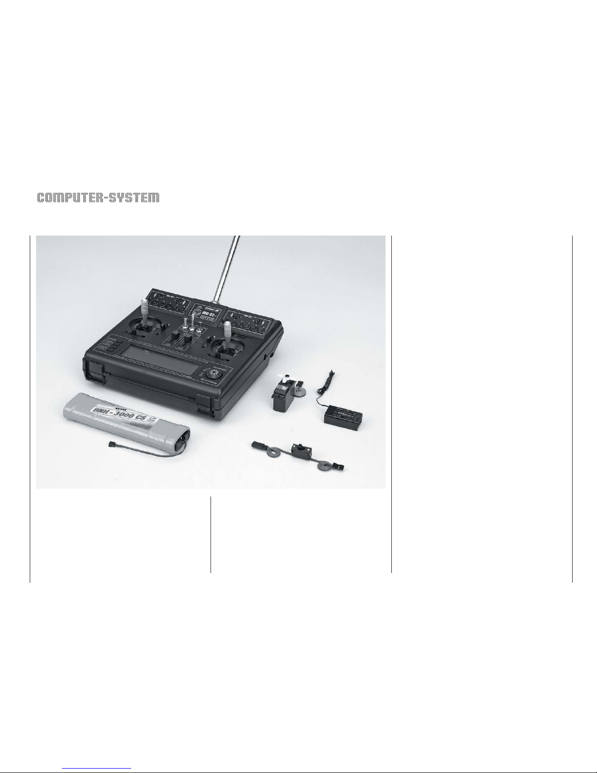
Set contents:
mc-22s micro-computer transmitter with factory-fi tted
NiMH transmitter battery, can be expanded from six
to max. ten proportional control functions.
Synthesizer RF module on the appropriate frequency.
R16
SCAN PLL Synthesizer FM receiver on the same
frequency (max. eight servo functions), C 577 servo,
Switch harness,
4.8 V NC receiver batteries: see main GRAUPNER
FS catalogue.
Specifi cation - mc-22s computer system
Transmission system SPCM 20, PCM 20, PPM 18, PPM 24 -
switchable
Radio Frequency
section
Integral (10 kHz spacing), 35, 35B, 40 or
41 MHz band
Spot frequencies 35 MHz band: chan. 61 - 80, 281*, 282*
35 MHz B-band: channels 182 - 191
40 MHz band: 50 - 59 and 81 - 92
41 MHz band: 400 - 420*
Channel spacing 10 kHz
Max. control func-
tions
SPCM = 10, PCM = 10, PPM = 12
Control functions,
basic version
4 functions, with digital trims plus
2 proportional functions
Optional extra chan-
nel functions
4 proportional or switched
Channel pulse width 1,5 ms ± 0,5 ms
Control resolution SPCM 20: 10 Bit (1024 Steps),
PCM 20: 9 Bit (512 Steps)
Aerial Telescopic aerial, ten sections, approx.
1470 mm long
Operating voltage 9,6 ... 12 V
Current drain approx. 55 mA (excl. active RF module)
Dimensions approx. 225 x 215 x 70 mm
Weight approx. 980 g incl. transmitter battery
* To recharge the mc-22s system you will also need the transmit-
ter charge lead, Order No. 3022, and the receiver battery charge lead, Order No. 3021.
** 12 V power source required.
Please refer to the main GRAUPNER FS catalogue
for details of other chargers.
Recommended battery chargers (optional)
Order No. 6422 Minilader 2
Order No. 6427 Multilader 3
Order No. 6426 Multilader 6E*
Order No. 6428 Turbomat 6 Plus*
Order No. 6429 Turbomat 7 Plus*
Automatic battery chargers with special NiMH charge
programs:
Order No. 6419 Ultramat 5*, **
Order No. 6410 Ultramat 10*,
Order No. 6412 Ultramat 12*, **
Order No. 6414 Ultramat 14*,
Order No. 6417 Ultramat 25*, **
Order No. 6416 Ultra Duo Plus 30*, **
Specifi cation - R16SCAN receiver
Type PLL-SCAN narrow-band
FM SUPERHET synthesizer receiver
35 / 35B MHz band
40 / 41 MHz band
Order No. 7052
Order No. 7054
Spot frequencies:
35 MHz
40/41 MHz
61 …282*/182 …191
50 … 92 /400 … 420*
Operating voltage 4,8 ... 6 V **
Current drain approx. 24 mA
Channel spacing 10 kHz
Sensitivity approx. 10 µV
Modulation PPM 18
Servo sockets 8 Stück***
Temperature range
approx. -15° ... +55 °C
Aerial length approx. 1000 mm
Dimensions approx. 46 x 25 x 15 mm
Weight approx. 17 g
* Channels 281, 282 and channels on the 41 MHz frequency
band are not approved for use in Germany. See page 168 for
frequency table.
** 4 NC / NiMH cells or 4 dr y cells
*** Servo 8 is connected to the socket marked “8 / Batt.” using a Y-
lead Order No. 3936.11 or 3936.32, in parallel with the receiver
battery.
Replacement part
Order No. 4300.6 Telescopic transmitter aerial
Stainless steel telescopic aerial
Order No. 4300.60
10-section telescopic aerial, ultra-robust construction.
Can be used instead of the standard telescopic aerial.
Please refer to the Appendix and the main GRAUP-
NER FS catalogue for details of additional accessories for the mc-22s radio control set.
Page 10
10
Operating notes
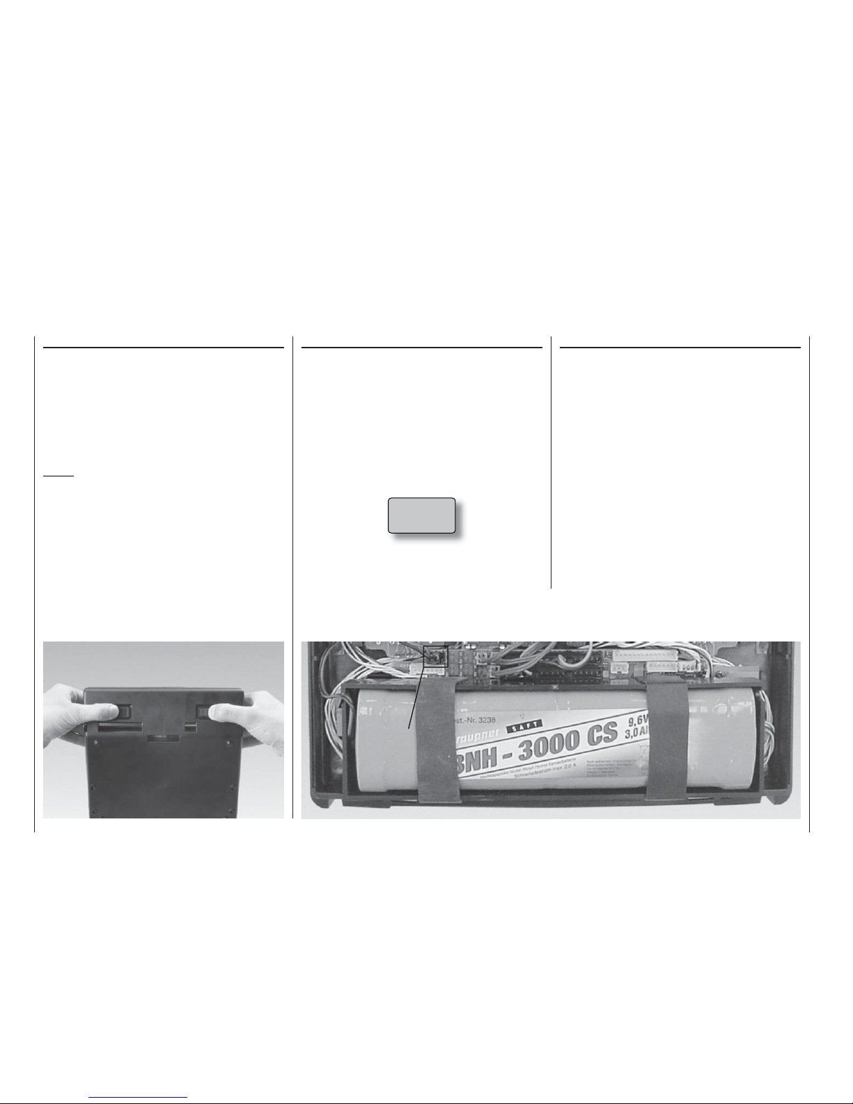
Opening the transmitter case
Before opening the transmitter, please check that it is
switched off (move Power switch to “OFF”). Slide both
latches inwards as far as they will go, in the opposite direction to the arrows, until the case back can be
folded open and disengaged. To close the transmitter,
engage the bottom edge of the case back, fold the
panel up again and slide both latches outwards in the
direction of the arrows. Take care that no wires get
caught when you close the back.
Notes:
• Do not modify the transmitter circuit in any
way, as this invalidates your guarantee and also
invalidates offi cial approval for the system.
• Never touch the circuit boards with any metallic
object. Don’t touch any electrical contacts with
your fi ngers.
• Whenever you wish to work on the transmitter,
start by disconnecting the transmitter battery
from the transmitter circuit board to avoid the
possibility of short-circuits (see column at far
right).
Power supply
The battery compartment is fi tted as standard with a
high-capacity 9.6 V NiMH battery (8NH-3000 CS, Order No. 3238 – specifi cation may change). However,
this battery is not charged when the transmitter is delivered.
When you are using the transmitter you can monitor
the battery voltage on the LCD screen. If the voltage
of the transmitter battery falls below a certain point,
you will hear an audible warning signal. The screen
then displays a message reminding you that the
transmitter battery needs to be recharged:
Charging the transmitter battery
The rechargeable transmitter battery can be charged
via the charge socket fi tted to the side of the case.
The transmitter must be switched off and left at
“OFF” for the whole period of the charge process.
Never switch on the transmitter when it is still
connected to the charger; even a very brief interruption in the charge process can cause the charge voltage to rise to the point where the transmitter is immediately damaged by the excess voltage. Alternatively the interruption may trigger a
new charge cycle, which means that the battery
will inevitably be totally overcharged.
For this reason check carefully that all connectors are
secure and are making really good contact. Interruptions due to an intermittent contact, no matter how
brief, will inevitably cause the charger to malfunction.
Operating notes
Socket for transmitter battery
Socket for transmitter battery
Batt must
be recharged!!
Page 11
11
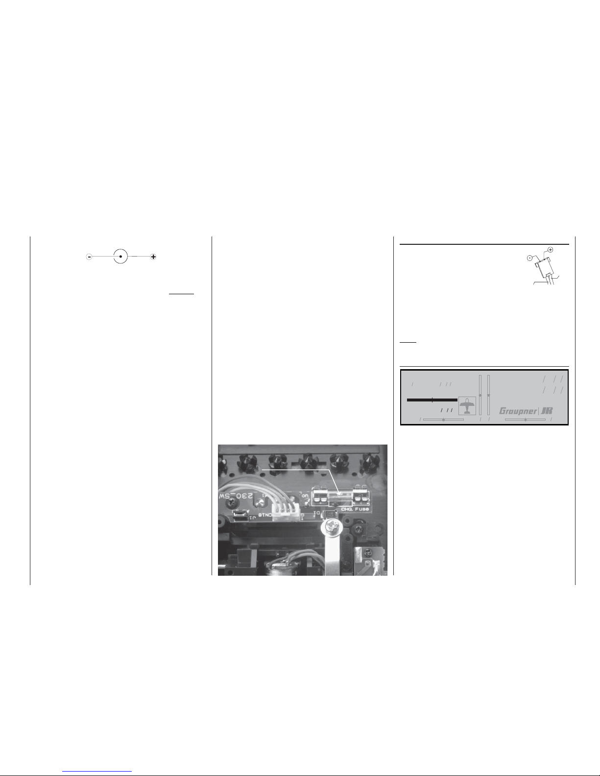
Polarity of the mc-22s charge socket
Commercially available battery charge leads produced by other manufacturers are often made up
with reversed polarity. For this reason use genuine
GRAUPNER charge leads exclusively.
Charging the transmitter battery using a standard
charger
The integral transmitter charge socket is fi tted with a
safety circuit which prevents reverse current fl ow. This
is designed to prevent damage to the transmitter if
the charge lead is connected with reverse polarity, or
if the bare ends of the lead short out.
This protective measure makes it impossible to recharge the transmitter battery using an automatic
charger, as the charger is unable to check and monitor the battery voltage properly. Automatic chargers
usually respond to this by terminating the charge process prematurely, throwing up error messages or refusing completely to charge the pack.
The basic rule for charging a fl at battery with a standard charger (without automatic cut-off) is: charge
for fourteen hours at a current corresponding to one
tenth of the capacity printed on the pack. This is 300
mA for the transmitter battery fi tted as standard. It is
up to the user to terminate the charge at the correct
time …
Charging the transmitter battery with an automatic charger
By-passing the reverse fl ow safety circuit
If you wish to use an automatic charger to recharge
the transmitter battery, the reverse fl ow safety circuit
(protective diode) mentioned in the previous column
must be by-passed. This is done by fi tting a 20 mm
cartridge fuse (5 Amp, fast-acting) in the fuse holder.
If you by-pass the reverse fl ow safety circuit, there is a constant danger of short-circuit between
the charge lead plugs. If a short-circuit or reverse
polarity occurs, the transmitter’s charge circuit fuse
will immediately blow.
A blown fuse must always be replaced by a new
20 mm glass cartridge fuse (5A, fast-acting). Never
attempt to repair the fuse by by-passing it. Replacement fuses are available in any electronics supply
shop.
Maximum charge current
To avoid damage to the transmitter the maximum
charge current should not exceed 500 mA (0.5 A)
with the charge circuit fuse out of circuit (not fi tted);
with the charge circuit fuse in place: max. 1.5 A.
Removing the transmitter battery
To remove the transmitter battery,
carefully disconnect the plug from
the transmitter circuit board, pulling
the connector upwards by the cable.
Locate the rubber bands at the battery compartment and push them
to the side slightly. The battery can
then be slid out of the compartment
sideways.
Check the state of the batteries at regular intervals.
Don’t wait to recharge the batteries until you notice
the servos working more slowly than usual.
On-screen battery operating hours display
#01 0:00h C73
H-J Sandbrunner
11.3V
0:00h
0 0 0 0
St watch
Flighttm
0 00
0 00
:
:
This timer shows the cumulative operating time of the
transmitter battery since the last time the battery was
recharged.
This timer is automatically reset to the value “0:00” as
soon as the transmitter circuit detects that the voltage
of the transmitter battery is signifi cantly higher than
last time, i.e. the pack has been recharged in the meantime.
Transmitter charge
plug polarity
brown or
black
red
Operating notes
Fuse, 5A, fast-acting
Fuse, 5A, fast-acting
Page 12

12
Operating notes
Operating notes
Charging the receiver battery
A wide variety of rechargeable 4.8 V NC and NiMH
batteries is available, varying in capacity. For safety
reasons always use ready-made battery packs from
the GRAUPNER range; never use dry cells.
There is no direct method of checking receiver battery voltage when operating a model.
For this reason it is important to make it a standard part of your routine to check the state of
your batteries at regular intervals. Don’t wait until
you notice the servos running more slowly than
usual before recharging the packs.
The charge lead, Order No. 3021, can be connected directly to the NC receiver battery for charging.
If the battery is installed in a model and you have installed one of the following switch harnesses: Order
No. 3046, 3934, 3934.1 or 3934.3, the battery can be
charged via the separate charge socket, or the charge socket which is built into the switch. The switch on
the switch harness must be left at the “OFF” position
for charging.
Standard chargers
Order No. 6422 Minilader 2
Order No. 6427 Multilader 3
Order No. 6426 Multilader 6E*
Order No. 6428 Turbomat 6 Plus*
Order No. 6429 Turbomat 7 Plus*
Automatic chargers with special NiMH charge
programs
Order No. 6419 Ultramat 5*, **
Order No. 6410 Ultramat 10*, **
Order No. 6412 Ultramat 12*, **
Order No. 6414 Ultramat 14*, **
Order No. 6417 Ultramat 25*, **
Order No. 6416 Ultra Duo Plus 30*, **
* To recharge the mc-22s system you will also need the transmit-
ter charge lead, Order No. 3022, and the receiver battery charge lead, Order No. 3021.
** 12 V power source required.
Please refer to the main GRAUPNER FS catalogue
for an overview of batteries, battery chargers and
measuring equipment.
General notes on battery charging
• Keep to the recommendations provided by the manufacturers of the charger and the battery at all times.
Observe the maximum permissible charge current
stated by the battery manufacturer. To avoid damage to the transmitter circuitry, the maximum charge current for the transmitter battery is 1.5 A; limit
the charge current to this value on the charger.
If you wish to charge the transmitter battery at a
current higher than 1.5 A, it is absolutely essential to remove the pack from the transmitter for
charging. If you ignore this, you risk damaging the
transmitter circuit board by overloading the tracks
and / or overheating the battery.
• If you are using an automatic battery charger, carry out a series of test charges to ensure that the
automatic charge termination circuit works correctly with your battery.
This applies in particular if you are recharging the
standard NiMH battery using an automatic charger
designed for NiCd batteries.
You may need to adjust the Delta Peak trigger vol-
tage, if your charger provides this option.
• Do not discharge the battery or carry out a battery
maintenance program via the integral charge socket. The charge socket is not suitable for this application.
• Always connect the charge lead to the charger
fi rst, and only then to the transmitter or receiver
battery. Observing this rule eliminates the danger
of accidental short-circuits between the bare contacts of the charge lead plugs.
• Never leave batteries on charge unsupervised.
Polarity of receiver battery
Page 13
13
Operating notes
Adjusting stick length
Both sticks are infi nitely variable in length over a
broad range, enabling you to set them to suit your
personal preference to provide fi ne, accurate control.
Loosen the retaining screw using a 2 mm allen key,
then screw the stick top in or out to shorten or extend
it. Tighten the grubscrew again carefully to lock the
set length.
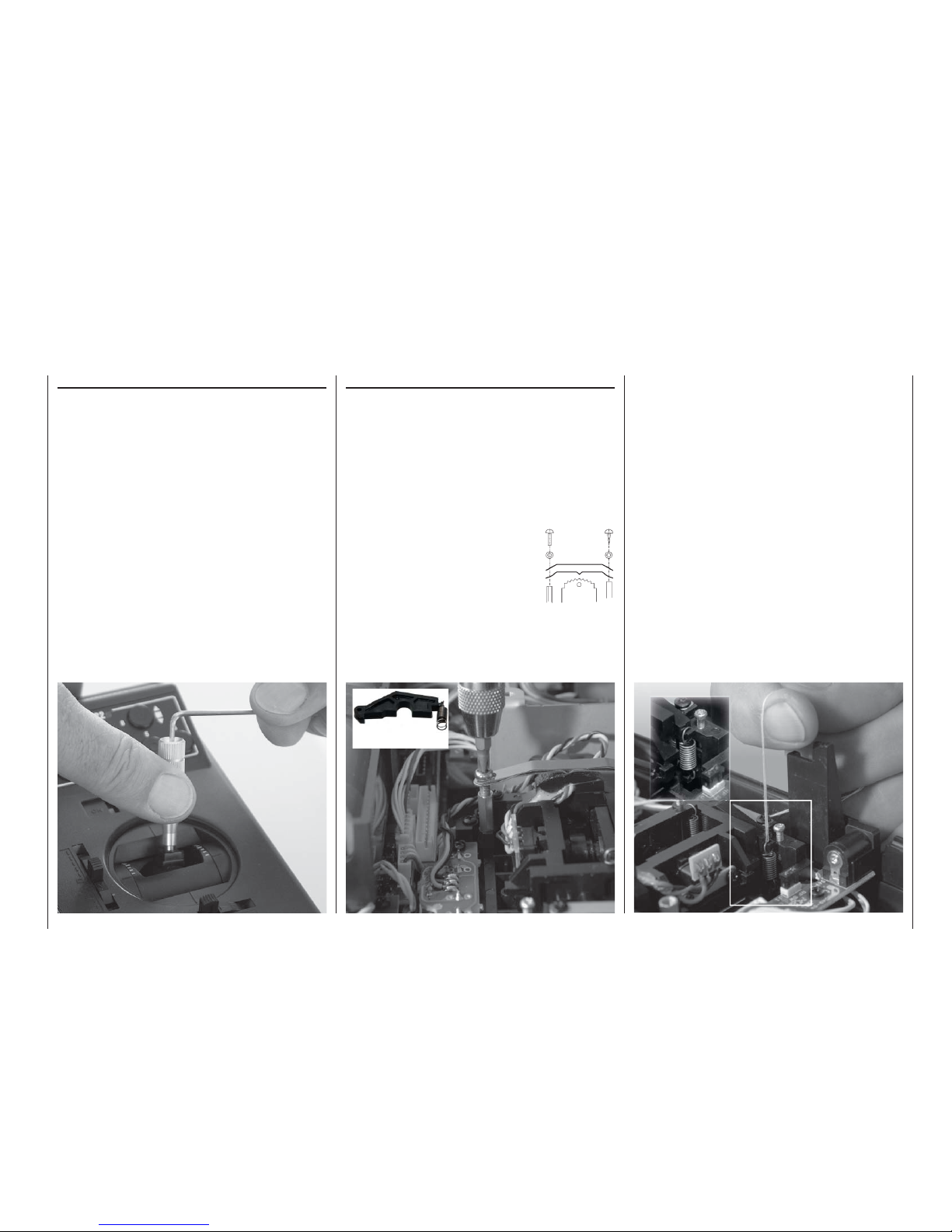
Changing the stick mode
Either or both sticks can be converted from self-neutralising to non self-neutralising (ratchet) action: open
the transmitter as already described.
If you wish to change the standard setting, use this
procedure:
1. Disconnect the centring spring from the appropriate neutralising arm using a pair of tweezers. If you
are not sure, move the stick to check. Raise the
neutralisation return arm and disconnect it.
2. Fix the ratchet spring (supplied)
to the plastic pillar using the black
self-tapping screw, then screw the
M3 screw in or out to set the desired spring force on the side of the
hexagon sleeve.
3. Check that the stick functions
work correctly, then close the
transmitter case again.
Brass
pillar
Changing back to “self-neutralising” action
Open the transmitter as already described.
1. Remove the ratchet spring, as shown in the illustration on the left.
2. Now re-connect the neutralising lever on the side
of the stick unit where the ratchet spring was located.
3. First loosen the stick force adjustment screw
slightly – see the illustration on the next page –
and then draw a length of thin thread through the
top loop in the spring, but without tying it. Connect
the spring to the bottom loop of the adjustment
system using a pair of tweezers, then pull the top
end of the spring up using the thread, and connect
it to the neutralising lever. Once the spring is positioned correctly, withdraw the thread again.
4. Adjust the stick centring spring force as described
in the next section.
Neutralising lever
Page 14
14
Operating notes
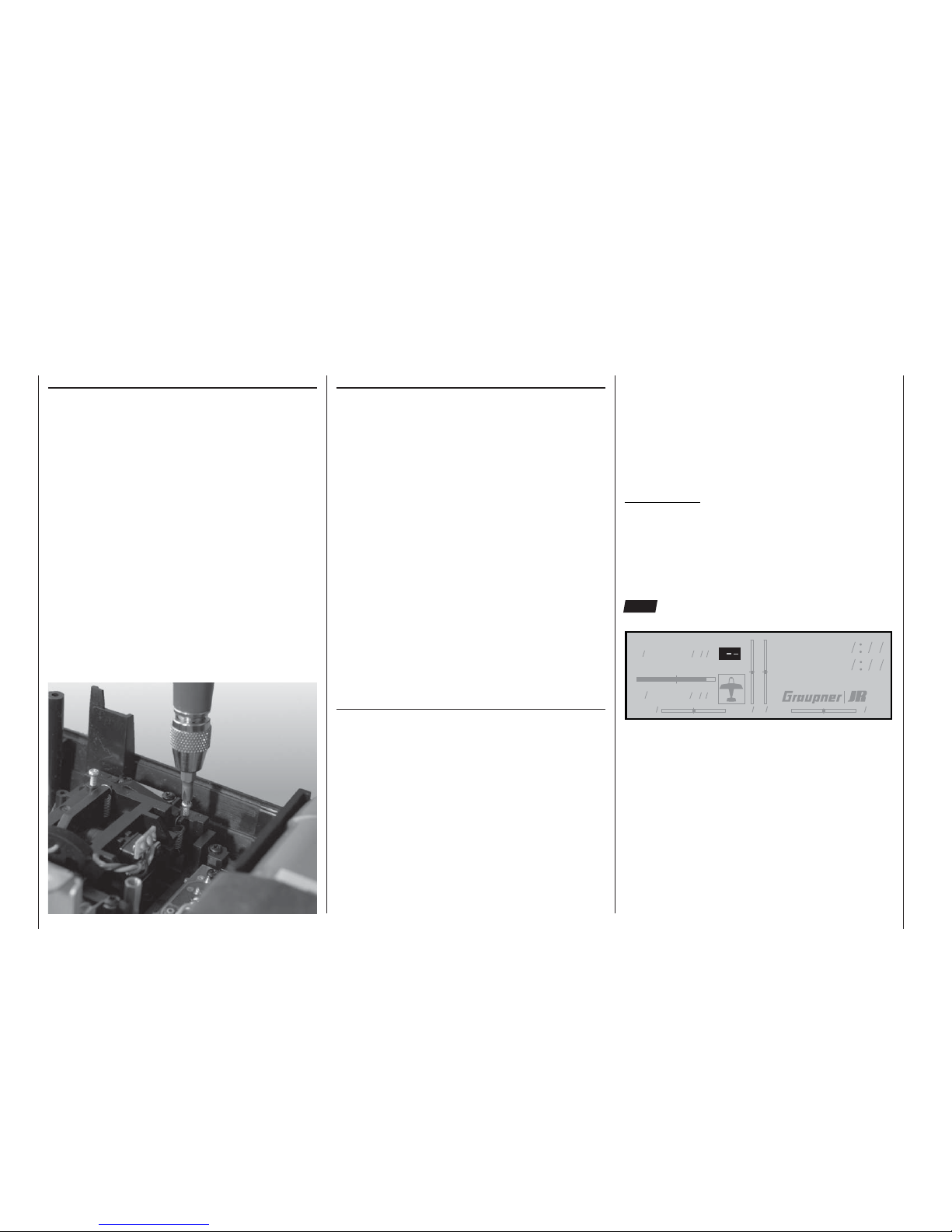
Stick centring force
The tension of the stick unit centring springs can be
adjusted to suit your personal preference: the adjustment system is located adjacent to the centring
spring. Rotate the adjustor screw with a cross-point
screwdriver to set your preferred spring force:
• Turn to the right (clockwise) = spring force harder;
• Turn to the left (anti-clockwise) = spring force softer.
Operating notes
Changing frequency bands and channels
The mc-22s transmitter is equipped as standard with
a PLL Synthesizer RF module. The channel you wish
to use is selected using the rotary control; plug-in
crystals are not required for the transmitter.
A detailed description of the procedure for using the
Synthesizer module and setting the appropriate channel is found in the section entitled “Using the transmitter for the fi rst time – selecting channels” on page 22.
The set channel is displayed on the screen. A security
system prevents an RF signal being generated when
the transmitter is switched on. The RF module must
fi rst be activated in the software, which provides an
additional margin of safety.
Two sets / two transmitters are available for the 35 /
35B MHz band and the 40 / 41 MHz band:
Radio control sets:
Order No. 4737 35 / 35B MHz band
Order No. 4738 40 / 41* MHz band
Transmitters alone:
Order No. 4737.77 35 / 35B MHz band
Order No. 4738.77 40 / 41* MHz band
* Channels 281 and 282 in the 35 MHz band, and all channels in
the 41 MHz band, are not approved for use in Germany. Please
refer to the frequency table on page 168, The table also lists the
channels which may legally be used for the various model types, i.e. model aircraft, model boats and model cars.
Please refer to the frequency table on page 168 for
a list of the channels which are valid in the European
continent at time of going to press.
The receiver must be operated on the same channel
and on the same frequency band as the transmitter.
You can use any GRAUPNER PLL Synthesizer receiver with the transmitter, together with all earlier
crystal-controlled GRAUPNER receivers, provided
that they are compatible with the transmission modes PCM20, SPCM, PPM18 and PPM24 (see pages
7 and 8 and the main GRAUPNER FS catalogue for
more information on this subject).
If you wish to use earlier crystal-controlled GRAUP-
NER receivers, it is essential to use genuine GRAUPNER FMsss plug-in crystals exclusively (see page
168). The receiver crystal is marked “R” (Receiver),
and should be pushed fi rmly into the socket in the receiver.
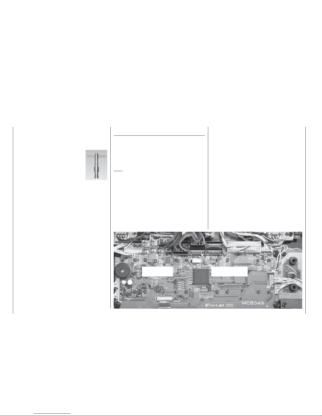
Important note:
The RF-Synthesizer module is connected to the
transmitter circuit board by means of two cables. If the
cables are not plugged in correctly, or if the 4-pin plug
is withdrawn in order to install a Pupil module (see
page 163), the transmitter switches directly to the
basic display when switched on. Instead of a channel
number, the screen now displays the fl ashing symbol
“C––” ; in order to indicate that the RF module is not
ready for use:
-ODELNAME
H#
(*3ANDBRUNNER
6
H
3TWATCH
&LIGHTTM
Changing frequency bands:
For reasons of safety a switch of RF module from the
35 / 35B MHz to the 40 / 41 MHz band (or vice versa) can only be carried out by a GRAUPNER Service
centre.
Page 15
15
Operating notes
Re-positioning the telescopic aerial
Screw the ten-section telescopic aerial into the balland-socket base. The angle of inclination of the aerial
can be adjusted mechanically as follows: loosen the
cross-point screw to the side of the socket, swivel the
aerial to your preferred angle, then carefully tighten
the screw again.
Notes:
• When you switch on the transmitter, do not activate the RF module without the aerial screwed into its
socket. The telescopic aerial should always be extended to its full length for controlling a model “in
earnest”, and even for protracted testing.
• The fi eld strength radiated by the transmitter is at
its lowest in an imaginary line extending straight
out from the tip of the transmitter aerial. Never
point your aerial straight at the model in an attempt
to obtain good reception; the opposite is true.
Installing the transmitter support bars
The transmitter can be fi tted with the optional transmitter support system, Order No. 1127. This is the
procedure: open the transmitter and remove the case
back, which is prepared to accept the support system
bars. Locate the four holes in the case back which
are designed to accept the support bars, and push a
cross-point screwdriver through them from the rear to
clear the openings, twisting it gently to act as a drill.
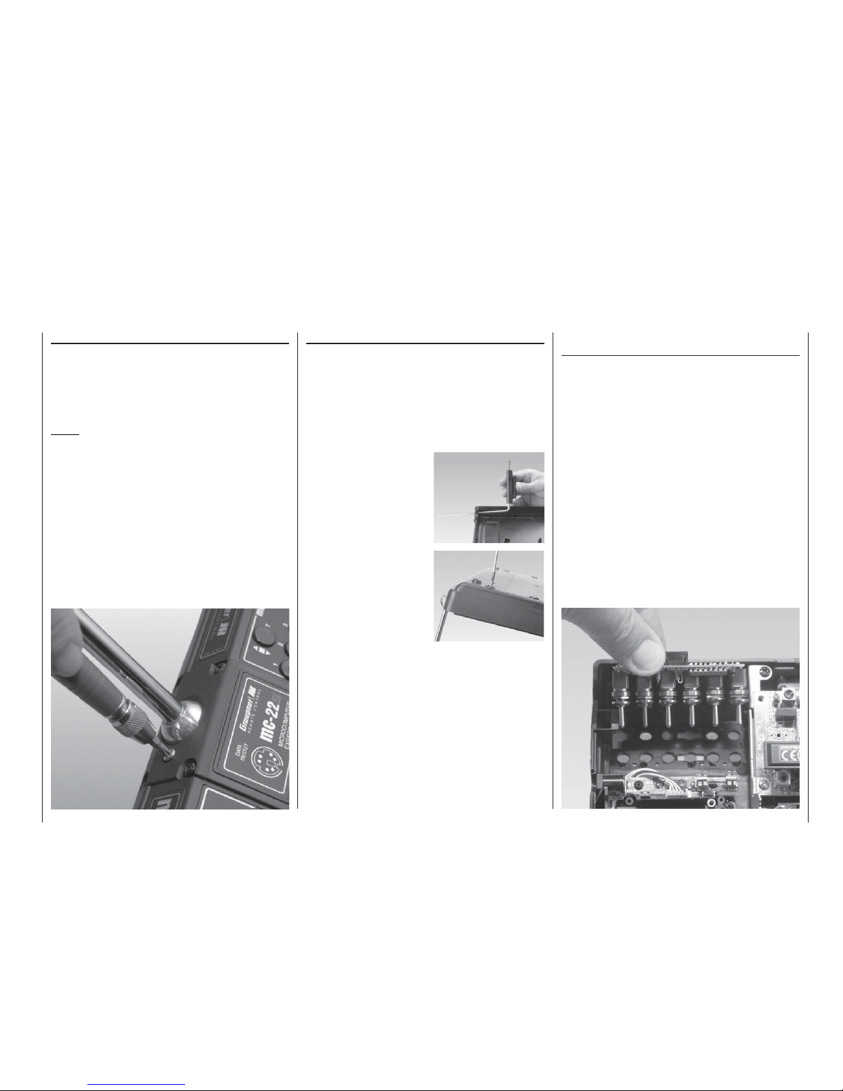
Installing NAUTIC modules, external switches,
switch modules and rotary modules
The transmitter case is supplied with all the holes for
the installation of optional modules already present.
Start by disconnecting the transmitter battery to avoid short-circuits.
The holes are sealed by blind grommets which can
easily be pushed out from the inside.
Using a suitable blunt instrument, press out the module covers on the front face of the transmitter from
the inside by pushing through the existing holes.
Place the new bezel in position, and check that it fi ts
correctly. Remove the backing paper from the adhesive surface of the bezel, position it carefully, then
press it down fi rmly. Peel the protective fi lm from the
printed front surface of the bezel. The module can
now be fi tted in the prepared module well from the inside, ensuring that the row of sockets on the module
faces the centre of the transmitter.
The support bars are held in place under strong tension by a long spring. If you fi nd the spring tension uncomfortably high, shorten the spring accordingly.
Slide the plastic retainer bracket for the metal
bars between the lugs in
the back panel, and fi t two
screws from the underside
into each bracket.
Now push the metal bars
of the support system
through the holes in the
back panel, working from
the inside.
Page 16
16
Operating notes
Operating notes
Secure the module using the nuts and rotary knobs
which you previously removed from the potentiometers and switches. Screw the nuts onto the shafts on
the outside of the transmitter and tighten them carefully using a suitable box spanner.
Socket assignment on the transmitter circuit
board
You will fi nd on a sketch of the transmitter circuit
board on page 19.
Additional transmitter controls can be connected to
function sockets CH5 ... CH10 on the transmitter circuit board; these include rotary controls, sliders and
switch modules (see Appendix).
Note:
Two additional inputs can be assigned to controls
such as external switches by software, so that up to
twelve separate control functions are available at the
transmitter when using the DS 24 FM S receiver.
In its standard form the transmitter features two 2channel sliders installed in the centre console; these controls are connected to sockets CH6 and CH7
as standard. If you wish, you can reverse the direction
of operation of the transmitter control “mechanically” by turning the connector through 180° at the transmitter circuit board. However, a more elegant method
is to use the »Control adjust« menu, where you can
reverse and adjust the transmitter controls using the
system software.
The external switch sockets can be assigned in any
arrangement you wish, as you defi ne the external
switch for software assignment simply by operating it,
which means that the number of the socket is irrelevant.
However, in the interests of clarity and comprehensibility we do recommend that you assign the sockets
in numerical order, and install the corresponding switches in the proper sequence – from 0 to max. 7 – in
the transmitter case, insofar as that is possible.
The NAUTIC module (Order No. 4141 or 4108) or the
Teacher module (Order No. 3290.2 or 3289) can be
connected directly to the 14-pin connector using the
mc-22(s) / mc-24 adaptor (Order No. 4184.1). If you
install the mc-22(s) interface distributor, Order No.
4182.3, you can connect both modules to the transmitter in parallel. A full description of the individual modules is included at the appropriate point in this
manual.
The last step is to fi t the rotary knobs on the potentiometer shafts, line them up with the graduated scale,
and tighten the grubscrews.
External switches, rotary modules and switch modules are installed in a similar way.
Take great care not to touch the solder pads on the
transmitter circuit board with any metallic object.
We recommend the use of the special box
spanner, Order No. 5733, for tightening the
decorative nuts which retain the external switches.
External switch
sockets 0 ... 7
Function sockets
CH5 ... CH10
Page 17
17
Operating notes
The original function of this socket was for “Direct
Servo Control”, and that’s why the abbreviation is still
in use. However, it is now much more versatile than
simply providing a means of controlling servos by cable. The DSC socket can now be used as an alternative to the Teacher socket (see pages 115 and 162),
also as an interface for fl ight simulators.
For the DSC connection to work you must check
the following:
1. Carry out any adjustments required in the approp-
riate menus:
If you are connecting the transmitter to a fl ight si-
mulator (for example), these settings are found in
the »Modulation« line of the »Base setup mo-
del« menu – “PPM” is usually required.
If you are connecting a Diagnosis lead (Order No.
4178.1), the modulation must be selected to suit
the receiver – see below.
2. Always leave the transmitter’s On / Off switch in
the “OFF” position, for only at this setting is the RF
section of the transmitter module switched off (no
RF signal) even when the DSC lead is plugged in.
This is particularly important if you are using a Diagnosis lead, otherwise you could still cause interference to other pilots.
3. Connect the appropriate connecting lead to the
optional DSC socket on the back of the transmitter. This renders the transmitter ready for use, circumventing the channel select process, and the
LCD screen operates. At the same time the letters “DSC” appear on the LCD screen, instead of
the usual display of the transmission channel you
have selected.
4. Connect the other end of the connecting lead to
the desired piece of equipment, after referring to
the operating instructions supplied with it. If you
wish to use the Diagnosis lead, Order No. 4178.1,
do not connect it directly to the receiver. First con-
DSC socket
Direct Servo Control
Environmental
protection notes
nect the lead to a receiver battery using a Y-lead
(Order No. 3936.11 or 3936.32), and connect this
to the receiver’s battery input socket instead of the
receiver battery. The end with the barrel plug can
then be connected to the appropriate socket on
the back of the transmitter. Once the transmitter
is connected to the receiver as described above,
you can check the control functions or make changes to settings even if another pilot is using “your”
frequency. Since (power = “OFF”) the transmitter does not broadcast a radio signal in this state,
you can, for example, prepare your model ready
to fl y without causing interference to other pilots.
Another advantage is that the transmitter’s current
drain is reduced to only about 70 mA, since the
transmitter’s RF section is not active in this mode
of operation. Diagnosis mode operations therefore
extend the operating time of the transmitter battery
considerably.
Important:
Ensure that all the cables are fi rmly plugged in.
Note regarding fl ight simulators:
The range of fl ight simulators available commercially
is now very wide, and you may fi nd that it is necessary to swap over certain contacts at the battery plug or
the DSC module. Do not attempt this work yourself; it
must be carried out by a GRAUPNER Service Centre.
Caution:
Certain receivers – such as the R16
SCAN – feature
a battery socket to which a servo can also be connected via a Y-lead. In this case it is not possible
to use a DSC lead.
Notes regarding environmental protection
Do not discard exhausted dry or rechargeable batteries in the ordinary domestic refuse. As end-user you
are legally required (by the “Battery Regulation”) to
return old and exhausted dry cells and rechargeable accumulators. For example, you can take them to
your local community recycling centre, or to any retail
outlet where batteries of the same type are sold.
The presence of this symbol on a product, in the user instructions or the packaging, means that you must not dispose of that item, or the electronic components contained within it, in the ordinary
domestic waste when the product comes
to the end of its useful life. The correct method of disposal is to take it to your local collection point for recycling electrical and electronic equipment. Dry cells
and rechargeable batteries must be removed from the
device and taken separately to a suitable battery disposal centre.
Individual markings indicate which materials can be
recycled and re-used. You can make an important
contribution to the protection of our shared environment by re-using the product, recycling the basic materials or re-processing redundant equipment in other
ways.
If you don’t know the location of your nearest disposal
centre, please enquire at your local council offi ce.
Page 18
18
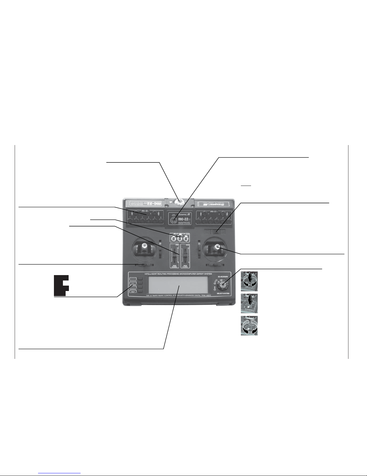
Description of transmitter
Ball / socket aerial base
Storage well on back panel
Option well for PC interface, Order No. 4182
Option wells
Locations for external switches, switch modules,
rotary modules, NAUTIC modules; see Appendix.
Switches and function modules
• 3 external switches as standard
• 2 sliders as standard
Digital trims
For fi ne adjustment of servo (neutral) position. A
brief push produces a single increment of offset
(increment size variable in »Base setup model«
menu). The screen shows the trim position.
Operating buttons:
ENTER Input button
ESC Return button
CLEAR Erase button
HELP Help button
LCD screen
See page 20 for a full description.
Contrast adjustment: press rotary control and rotate simultaneously.
Warning signals:
• If battery voltage falls below set threshold
• If Trainer system malfunctions
• If Channel 1 stick is at full-throttle when transmitter is switched on
• If Fail-Safe settings are not correct
ON / OFF switch
Note:
Always switch the transmitter on fi rst, then the
receiver. After a fl ight: switch the receiver off
fi rst, then the transmitter.
Stick units
Two dual-axis stick units providing four independent
control functions. Variable-length sticks. The primary control functions (i.e. stick mode) can be assigned
within the »Base setup model« menu, e.g. throttle
left or right. The throttle stick can also be set to selfneutralising or ratchet action; see page 13.
Rotary control, provides two-level control
(normal and pressed-in)
Switches between individual lines within a menu when
held pressed-in.
Changes the input fi eld, or confi rms your input, when
pressed briefl y.
A brief press on the rotary control at the basic display
switches to »Servo display«.
If rotated in its normal (non-pressed) state, the rotary control selects the desired Code from the list in the
multi-function menu. If you call up a menu point, the
rotary control also changes the entered value in an inverse-video fi eld which appears at the bottom edge of
the screen in (light characters on dark background).
Set values take effect immediately, and are also stored
immediately.
Description of transmitter
Page 19
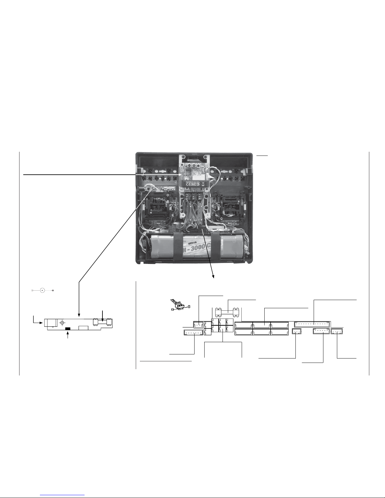
19
Description of transmitter
Note:
Whenever you intend to work on the interior
of the transmitter, remember to disconnect the
transmitter battery from the power socket.
Take great care not to touch soldered joints with
any metallic object, as this could cause a shortcircuit.
It does not matter which way round you connect the
external switches.
Reversing the orientation of the control connector
simply reverses its direction of effect.
Synthesizer RF module:
The channel is selected in the software when you
switch the transmitter; see page 22.
For safety reasons the RF module can only be switched from the 35 / 35B MHz to the 40 / 41 MHz band
(or vice versa) by an authorised GRAUPNER Service
centre.
RF module
socket
(4-pin)
Socket for
connection
to RF Syn-
thesizer
module
Service socket (for
use by GRAUPNER
Service Centres only)
Sockets 0 ... 7 for
external switches
(see Appendix)
DSC module*
socket
* DSC = Direct Servo Control.
see page 17 and Appendix
Battery socket
Battery plug
polarity
Transmitter fuse,
0.5A, fast-acting
Function sockets CH5 ...
CH10 for transmitter controls (rotary knobs, switch
module, slider module;
see Appendix)
Interface distributor socket
Transmitter circuit board
0
2
4
6
7
1
35
CH5 CH7 CH9
CH6
CH8 CH10
Charge socket
Battery charge circuit fuse
(5A, fast-acting) for use
with automatic chargers;
see page 11.
Jumper for service use:
do not touch!
Polarity of charge socket
Page 20
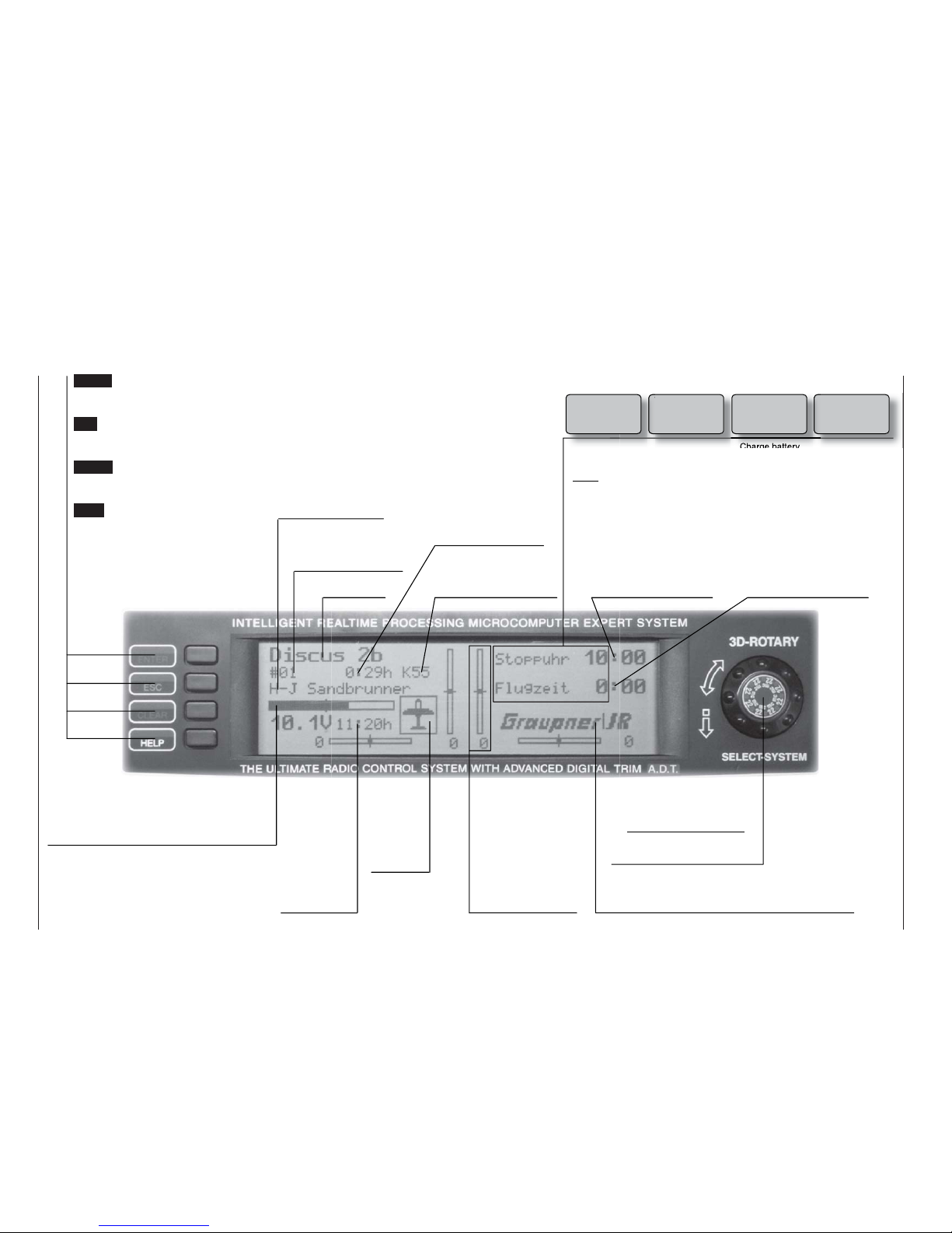
20
Description of LCD screen
ENTER (Input button):
Switch to multi-function list, call
up a menu
ESC (Escape button)
Return step by step from any
menu to the basic display
CLEAR (Erase button)
Resets altered values to default
settings
HELP (Help button)
Provides a brief help message relating to any menu
Model name
Model memory
1 ... 30
User’s name
(max. 15 characters)
Number of the selected
transmission channel
Model operating time
Superimposed warning messages*:
Notes:
* If the transmitter battery voltage is too low, the message “Not currently pos-
sible; battery voltage too low” appears in the »Model Select« and »Copy /
Erase« menus.
** For safety reasons this warning can only be disabled by selecting an unpowe-
red fi xed-wing model: this is done by selecting “none” in the “Motor” line of the
»Model Type« menu; see page 52.
Stopwatch in minutes
(count-up / count-down)
Flight time in minutes
(count-up / count-down)
Battery voltage with dynamic bar display.
If voltage falls below the pre-set level a
warning message appears and a buzzer
sounds.
Transmit-
ter operating
time. This va-
lue is auto-
matically re-
set to zero
when the bat-
tery is re-
charged.
Model type
display:
fi xed-wing
aircraft or
helicopter
Display diagram for
all four digital trim
levers with numeric and directional
display: „“ or „“.
Special cut-off trim
for Ch. 1 (see page
32).
Dual-level rotary control
Adjusts screen contrast in
basic transmitter display
with control pressed in.
GRAUPNER logo; alternatively fl ight phase name,
Flight phases are selected using a physical switch
Description of LCD screen
Fail Safe
setup
Thr
too
high!
None
student signal
Trainer mode
problem
Throttle stick at
full-throttle**
Charge battery Only in PCM20
and SPCM20
mode
Batt must
be recharged!!
Page 21
21
Using the system for the fi rst time
Using the system for the fi rst time
Preliminary notes, selecting the menu language
Preliminary notes
In its default state the mc-22s transmitter is programmed to the PPM18 transmission mode, which suits
“FM-PPM” type receivers. If you have purchased
a standard radio control set on the 35 or 40 MHz
bands, you can immediately operate the supplied
R16
SCAN receiver using this transmission mode.
In addition to PPM18 the following transmission modes can be selected:
• PCM20 mode for all GRAUPNER/JR “mc” and “DS
mc” type receivers.
• SPCM20 mode for GRAUPNER/JR “smc” type re-
ceivers.
• PPM24 mode for the GRAUPNER/JR DS 24 FM S
receiver.
This mode switching facility enables the mc-22s
transmitter to operate all GRAUPNER receiving systems supplied to date, i.e. all receivers supplied with
PPM-FM and PCM transmitters (with the exception of
the FM6014 / PCM 18).
If you do not own a “PPM18” type receiver, this
means that you fi rst need to change the type of modulation to suit the receiver you wish to use. If you neglect to do this, the transmitter will not operate the receiver correctly.
The transmission mode can be set in the »Base se-
tup model« menu (description: page 50) for the current model, or pre-set in the »Basic settings« menu
(description: page 117) for all future model memories.
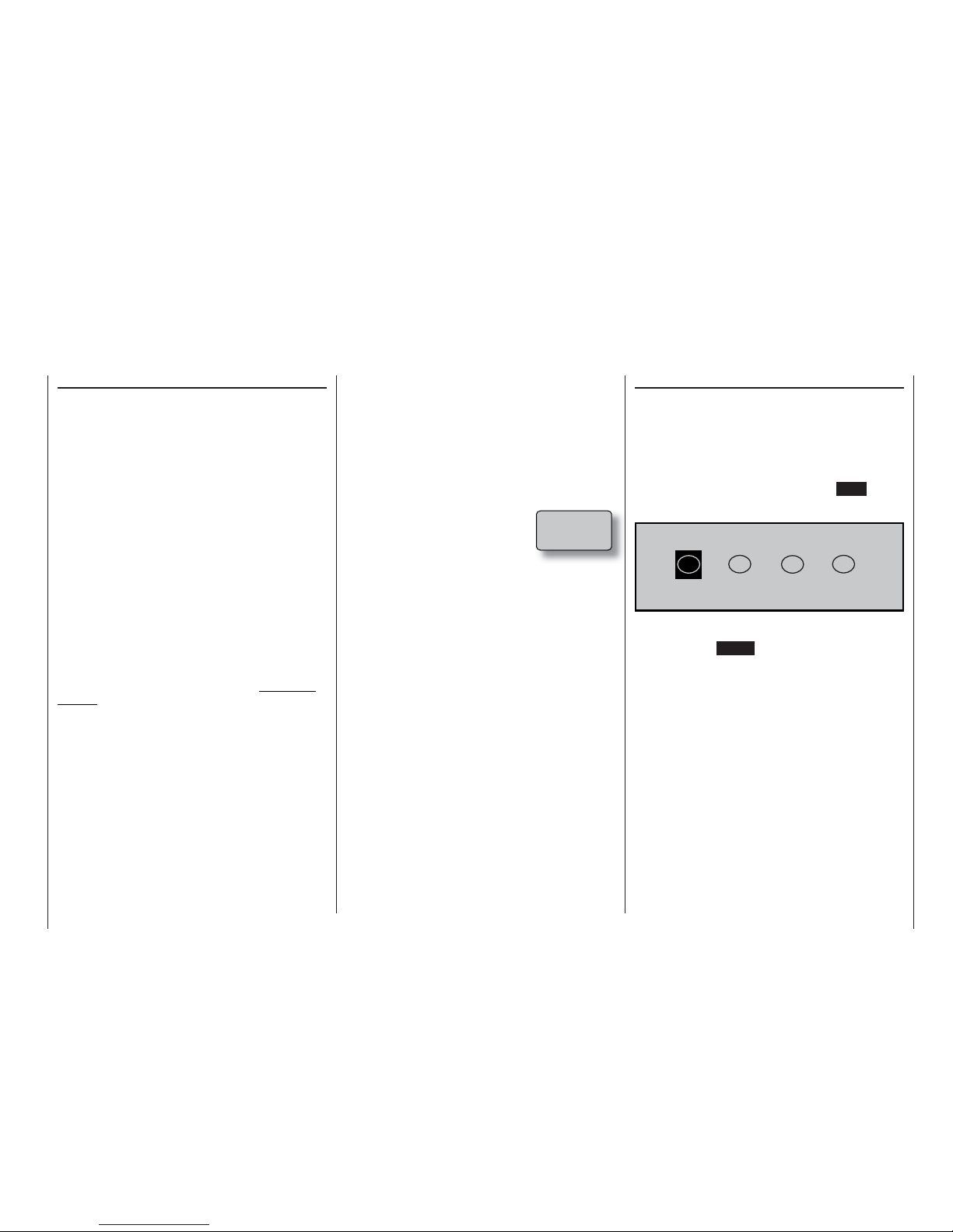
As standard, the two proportional sliders in the
transmitter’s centre console are connected to sockets
CH6 and CH7 on the transmitter circuit board. For the
purposes of further programming it does not matter
which socket numbers are assigned to the three switches on the “Multi Switch Board”.
Which crystals can be used?
The mc-22s requires no plug-in crystals. The transmission channel is selected by software: see the next
page.
Battery charged?
When you fi rst take delivery of your transmitter, the
battery will be in the discharged state, so you must
fi rst charge it as described on pages 10 … 12. If you
do not do this, the battery will soon
fall below the pre-set threshold voltage (approx. 9.3 V), and you will
see and hear a warning signal to
remind you to recharge it.
Aerial fi tted?
Never switch the transmitter on unless the aeri-
al is screwed in. Even for prolonged testing you
should always fi t the aerial and extend it fully,
otherwise the transmitter may malfunction, with possible damage to the RF module.
When you wish to control a model it is fundamen-
tally essential to screw the ten-section telescopic aerial into the transmitter and extend it fully.
Transmitter fi eld strength is at a minimum in an imaginary line extending straight out from the transmitter aerial. It is therefore fundamentally misguided to
“point” the transmitter aerial at the model with the intention of obtaining good reception.
Selecting the language
The mc-22s transmitter offers the facility to select any
of four languages:
• German
• English
• French
• Italian
To change the menu language, hold the HELP button
pressed in when you switch the transmitter on; you
will then see this display:
, / * . 1
You can now select the desired language by turning
the rotary control. A brief press on the rotary control
(or pressing the ENTER button) confi rms your choice.
All settings stored in the transmitter are retained
in full when you switch languages.
Batt must
be recharged!!
Page 22
22
Using the transmitter for the fi rst time
Selecting a channel
Switching the transmitter on / selecting a channel
Every time you switch the transmitter on you must
fi rst confi rm to the integral Synthesizer system that
you wish to use the set frequency. This takes the form
of a security query, intended to prevent you switching
the system on accidentally while the transmitter is set
to the wrong channel. The software asks you to confi rm: “HF off / on”. The last set channel is initially highlighted (inverse video – black background) and fl ashes:
C61
HF off
switch on Channel
N O
Y E S
è
If you wish to activate this channel, use the rotary
control to move to “YES”, and press ENTER, or press
the rotary control briefl y; this switches the RF module
on with the set channel. If not, move to the arrow „“
symbol. Press the rotary control or the ENTER button
to take you to the Channel Select list. The channels
available at that point vary according to the RF module currently fi tted:
Frequency band Channels
35 / 35 B MHz band 61 … 80/281, 282 and
182 … 191
40/41 MHz band 50… 92/400 … 420
K61 K62 K63 K64 K65 K66
K67 K68 K69 K70 K71 K72
K73 K74 K75 K76 K77 K78
K79 K80 K281 K282 K182 K183
K184 K185 K186 K187 K188 K189
K190 K191
Note:
Channels 281 and 282 in the 35 MHz band, and all
channels in the 41 MHz band, are not approved for
use in Germany. Please refer to the frequency table
on page 168, which lists the channels valid in the European continent at the time of going to press (information not guaranteed).
Use the rotary control to select the channel you wish
to use. However, please check before you do this that
no other model fl yer is operating a radio control system on the channel you intend to use. Press the rotary control, ENTER or ESC to confi rm your choice,
and the screen reverts to the previous screen page:
C73
HF off
switch on Channel
N O
Y E S
è
Now switch the RF module on as previously described, by moving the highlighted square to “YES”. The
selected channel number now appears (no longer
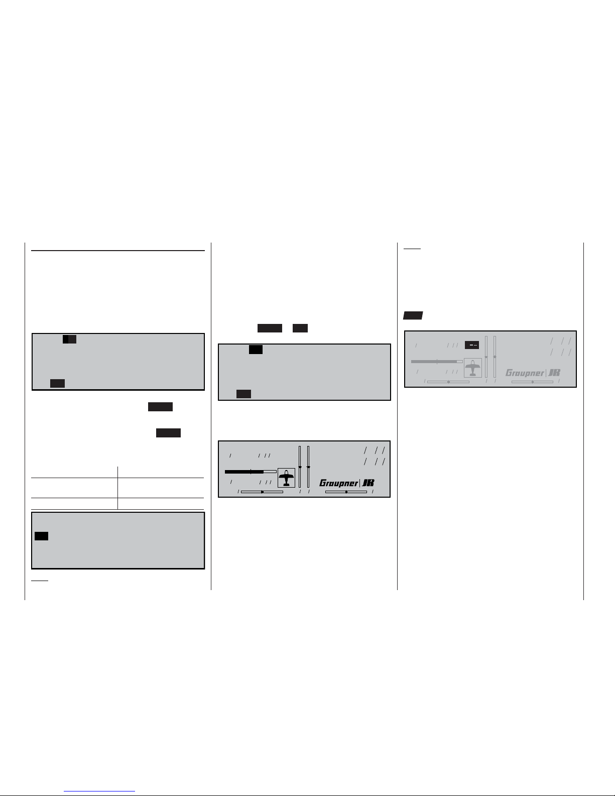
fl ashing) in the basic display:
#01 0:00h C73
10.3V
0:00h
0 0 0 0
St watch
Flighttm
0 00
0 00
:
:
The transmitter is now ready for use.
If you wish to change the channel again, the transmit-
ter must fi rst be switched off, then on again.
On page 46 you will fi nd a description of the basic
procedure for initially programming a new model memory; helpful programming examples are in the section starting on page 120.
Note:
The RF-Synthesizer module is connected to the
transmitter circuit board by means of two cables. If the
cables are not plugged in correctly, or if the 4-pin plug
is withdrawn in order to install a Pupil module (see
page 163), the transmitter switches directly to the
basic display when switched on. Instead of a channel
number, the screen now displays the fl ashing symbol
“C––”; in order to indicate that the RF module is not
ready for use:
#01 0:00h C
10.8V
0:00h
0 0 0 0
St watch
Flighttm
0 00
0 00
:
:
W A R N I N G
Never, ever, switch off the transmitter when you
are fl ying a model! If you do, you run a serious
risk of losing the model, as you will be highly unlikely to be able to re-activate the RF signal quickly enough, since the transmitter always responds
with the security query “RF signal on YES / NO”
when switched on.
Using the system for the fi rst time
Page 23
23
Using the receiver for the fi rst time
Using the system for the fi rst time
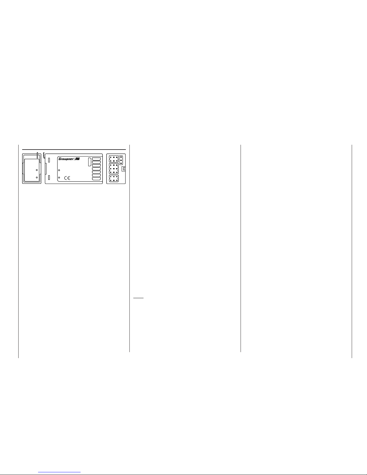
Receiving system
The mc-22s radio control set is supplied complete
with a PLL-SCAN narrow-band FM superhet receiver
on the 35 / 35B MHz band or the 40 / 41 MHz band.
The following section describes how to set the receiver channel to match the transmitter’s channel. The
approved channels at the time of going to press are
listed in the table on page 168.
As mentioned on page 21, the mc-22s transmitter is
pre-programmed to what is known as PPM18 mode,
which suits receivers of the “FM-PPM” type. If you
have purchased a standard radio control set on the
35 or 40 MHz bands, you can immediately operate
the supplied R16
SCAN receiver using this transmissi-
on mode.
If in the meantime you have changed the transmissi-
on mode, and you wish to use the receiver supplied
in the set, your fi rst task is to set the transmitter back
to PPM transmission. Next you should select the desired channel on the transmitter, as described on the
preceding page. However, you must not activate the
channel on the transmitter until you have checked carefully that no other pilot is fl ying his model on your
chosen frequency. When you are confi dent of this,
switch the receiver on. You will see a blue LED light
up on the receiver, indicating that the unit is (basically) ready for use.
7
6
5
4
3
2
1
8/Batt.
PLL-Synthesizer-MICRO-SUPERHET
R 1 6
FM
Best.-Nr.
7052
Kanal 60-282/182-19 1
für das 35MHz/35MHz-B-Band
SCAN LED
Made in Malaysia
S C A N
! #
LED SCAN
Antenne
Setting the receiver to match the transmitter
channel
1. Prepare the transmitter ready for use, with the aerial fi tted and extended, and place it in the immediate vicinity of the receiver. The scan program
which is run next binds the receiver to the most
powerful transmitter signal, so you must ensure that no other radio control transmitter is located
very close to your receiver.
2. Locate the push-button marked “SCAN” on the receiver, and use a tool such as a ball-point pen to
hold the button pressed in until the LED goes out;
this takes about three seconds.
3. When the LED is extinguished, press the SCAN
button again immediately: the LED now fl ashes at
a high rate. This indicates that the “Scan” process
is under way. As soon as the receiver “fi nds” the
transmitter frequency, the LED will light up again
constantly. The receiver stores this channel, so
that you do not need to repeat the process each
time you switch the receiver on; you only need to
do this if you change channels.
4. If the LED fl ashes slowly after a few seconds, it
is unable to lock onto the transmitter frequency.
Check the transmitter, then repeat steps 1 to 3.
Always carry out a range check with the model on
the ground before every fl ight.
Note:
If you wish to connect a servo in parallel with the receiver battery, i.e. to the socket on the R16
SCAN re-
ceiver marked “8 / Batt”, you need to use a Y-lead, Order No. 3936.11 or 3936.32.
Please read the information on installing the receiver
and receiver aerial on pages 3 to 5 of these instructions.
If you wish to use a different GRAUPNER recei-
ver (Synthesizer or crystal-controlled), please note
that you must set the appropriate transmission mode
(PPM18, PPM24, PCM20 or SPCM20) on the transmitter; the frequency band and channel number of the
receiver must also match those of the transmitter. Please refer to the main GRAUPNER FS catalogue for
details of the full range of receivers.
The R16SCAN receiver is fi tted with polarised connector sockets, so that the servos and battery can only
be connected the right way round. Genuine GRAUP-
NER plugs feature a slight chamfer on one side to
match the sockets. Connect the receiver battery to
the receiver socket marked “Batt” via an ON / OFF
switch harness.
Page 24
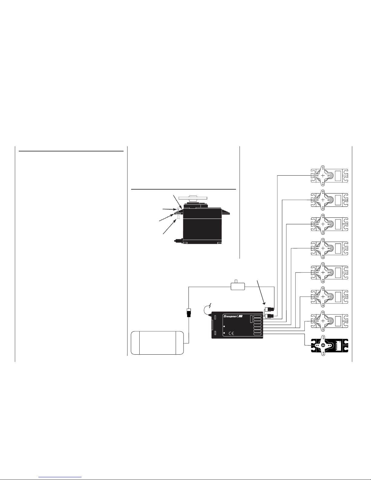
24
Using the system for the fi rst time
Installation notes
Installation notes
Your receiving system must be installed correctly in
the model. The following are a few suggestions when
using GRAUPNER equipment:
1. Wrap the receiver in (anti-static) foam rubber at
least 6 mm thick. Fix the foam round the receiver using rubber bands to protect it from vibration,
hard landings and crash damage.
2. The receiver aerial must be secured in the model,
so that there is no chance of it becoming tangled
in the propeller or control surfaces. However, it is
best not to deploy the aerial in an exactly straight
line, but to angle it: e.g. run it straight to the tailplane, then leave the fi nal 10 - 15 cm trailing freely,
as this avoids reception “blind spots” when the model is in the air. If this is not possible, we recommend that you lay out part of the aerial wire in an
S-shape inside the model, as close to the receiver
as possible.
3. All switches must be installed in a position where
they will not be affected by exhaust gases or vibration. The switch toggle must be free to move over
its full range of travel.
4. Always install servos using the vibration-damping
grommets and tubular metal spacers supplied. The
rubber grommets provide some degree of protection from mechanical shocks and severe vibration.
Don’t over-tighten the servo retaining screws, as
this will compress the grommets and thereby reduce the vibration protection they afford. The system
offers good security and vibration protection for
your servos, but only if the servo retaining screws
are fi tted and tightened properly. The picture on
the right shows how to install a servo correctly.
The brass spacers should be pushed into the rubber grommets from the underside.
5. The servo output arms must be free to move over
their full arc of travel. Ensure that no parts of the
mechanical linkage can obstruct the servo in its
movement.
The sequence in which the servos are connected to
the receiver is dictated by the model type. Please see
the socket assignments listed on pages 35 and 37.
Be sure to read the safety notes on pages 3 … 5.
Servo
4,8 V
C 577
Best.-Nr. 4101
7
6
5
4
3
2
1
8/Batt.
PLL-Synthesizer-MICRO-SUPERHET
Best.-Nr.
7052
Kanal 60-282/182-19 1
für das 35MHz/35MHz-B-Band
SCAN LED
Made in Malaysia
R 1 6
FM
S C A N
! #
Receiver battery
Receiver aerial
Switch harness
Y-lead, Order No.
3936.11 or 3936.32
If you are using the R16SCAN receiver, servo 8 is connected to the socket marked “8 / Batt.”, using a Y-lead Order No.
3936.11 or 3936.32, in parallel with the receiver battery.
Servo mounting
Servo mounting lug
Retaining screw
Rubber grommet
Brass tubular spacer
Page 25
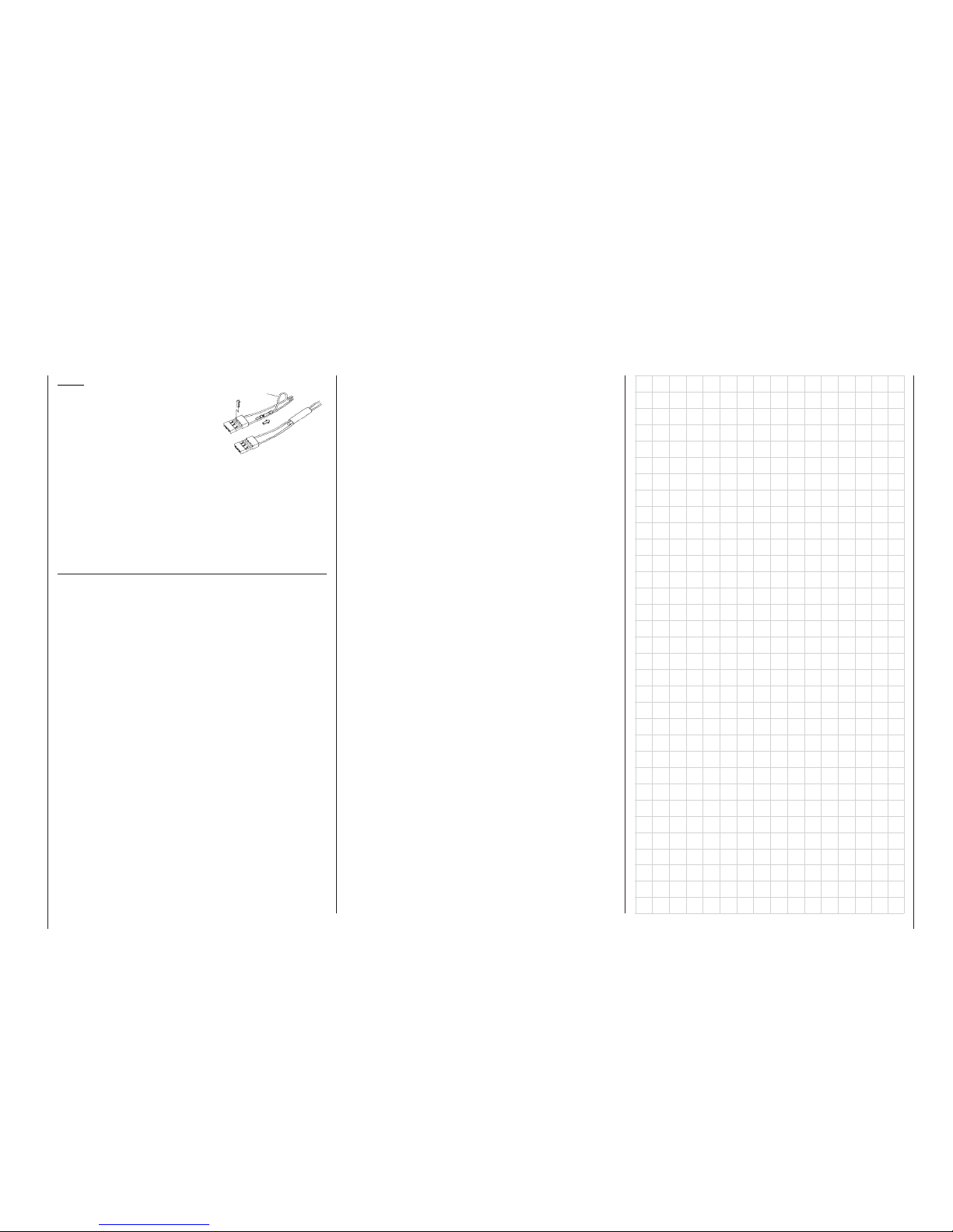
25
Using the system for the fi rst time
Note:
If you wish to use a receiver
battery and a speed controller
with integral BEC* system, the
positive (red) wire must normally be disconnected from
the 3-pin plug, although this
does vary according to the type of controller. Please
be sure to read the instructions supplied with your
speed controller before you do this.
Using a small screwdriver, carefully raise the centre
lug of the plug (1), withdraw the red wire (2) and insulate the exposed contact with insulating tape to prevent possible short-circuits (3).
* Battery Elimination Circuit
1
2
3
red
If the receiver is ever switched on when the transmitter is off, the servos may carry out uncontrolled movements. You can avoid this by switching the system on
in this order:
Always switch the transmitter on fi rst,
then the receiver.
When switching the system off:
Always switch the receiver off fi rst,
then the transmitter.
When programming the transmitter you must always
ensure that any electric motors in the system cannot
possibly start running accidentally, and that an I.C.
engine fi tted with an automatic starter cannot start
unintentionally. In the interests of safety it is always
best to disconnect the fl ight battery, or cut off the fuel
supply.
Range checking:
Before every session you should always check that
each working system is functioning correctly, and carry out a range check with the model on the ground.
The transmitter aerial should be fi tted but collapsed
completely. Walk away from the model holding the
transmitter. All the functions should work smoothly and correctly during this test, even at the limit of
ground-range. If your model is powered, repeat the
check with the motor running to ensure that it does
not cause interference.
Page 26

26
Defi nition of terms
Control functions, transmitter controls, function inputs, control channels, mixers, external
switches, control switches, fi xed switches
Defi nition of terms
To make it easier for you to understand the mc-22s
manual, the following two pages contain defi nitions
of many terms which crop up again and again in the
remainder of the text, together with a basic fl ow diagram showing the course of the signal from the transmitter control to the point at which it is radiated from
the transmitter aerial.
Control function
The term “control function” can be thought of as the
signal generated for a particular function which needs
to be controlled – initially regardless of its subsequent progress through the transmitter. In the case of
fi xed-wing model aircraft the control functions include
throttle, rudder and aileron, whereas collective pitch,
roll-axis and pitch-axis are typical of those used for
helicopters. The signal of a control function may be
assigned directly to one control channel, or to several control channels simultaneously via mixers. A typical example of the latter is separate aileron servos,
or paired roll-axis or pitch-axis servos in a model helicopter. In particular, a control function includes its infl uence on the mechanical travel of the corresponding
servo. This can be expanded or contracted by software, and the characteristic curve of its travel can also
be modifi ed from linear to extreme exponential.
Transmitter control
The term “transmitter control” refers to the mechanical elements on the transmitter which are operated
directly by the pilot. Their movements in turn generate
corresponding movements in the servos, speed controllers etc. at the receiver end. The transmitter controls include the following:
• The two dual-axis stick units for the control functions 1 to 4; these four functions can be interchanged in any way you like through software, e.g.
throttle left or right, without having to re-connect
the servos; this applies both to fi xed-wing model
aircraft and helicopters. The dual-axis stick func-
tion for throttle (or airbrakes) is often referred to as
the Ch1 (Channel 1) control.
• The two proportional sliders, which are connected to sockets CH6 and CH7 on the transmitter circuit board in the default confi guration. If an optional two-channel switch module (Order No. 4151.2
or 4151.3) is installed, it can be used to provide
three-position control of a servo, speed controller
or similar device (see Appendix, page 165).
Which transmitter control affects which of the ser-
vos 5 … max. 12 is entirely programmable, without
having to re-position connectors inside the transmitter, i.e. the default assignments can be changed at any time in the »Control adjust« menu
(pages 58 and 60). In the Heli menu the inputs 6,
7 and 12 are termed “Throttle”, “Gyro” and “Throttle limit” respectively, since helicopter-specifi c functions are operated using these inputs.
In the case of these six control functions the servos
follow the movement of the transmitter controls continuously and proportionally (in the case of the switch
module only three-position movement is possible, as
already mentioned).
For our purposes, and in physical terms, each transmitter control ends after the function input …
Function input
This is an imaginary point in the signal path, and
must not be considered the same as the point on
the circuit board where the transmitter control is connected! The two menus »Stick mode« and »Cont-
rol adjust« affect the course of the signal “after” these points, and it is possible (and likely) that there will
be differences between the number of the transmitter
control (as stated above) and the number of the subsequent control channel.
Control channel
There is a point in the signal path where the signal
contains all the control information required for a particular servo – this may be generated directly by a
transmitter control or indirectly via a mixer – and from
this point on we call the signal a control channel. This
signal is specifi c to an individual servo, and leaves
the transmitter via the RF module in order to actuate
the corresponding servo in the model.
Mixer
In the signal fl ow diagram you will see a wide range
of mixer functions. Their purpose is to enable a control function to affect multiple servos at the branching
point of the mixer input. The range of mixer programs
is extremely wide-ranging; for more information please refer to the numerous mixer functions as described in the section starting on page 84 of the manual.
External switch
The three standard two-position switches on the centre console, and other optional two-position and
three-position switches (see Appendix), can also be
incorporated into the programming of the transmitter controls, to provide two-position or three-position
control of a servo, speed controller or similar device.
A three-position switch operates in exactly the same
way as the two-channel switch module mentioned
above (see also the Appendix, page 165).
However, all these external switches are also capable of controlling various program options, e.g. starting and stopping timers, switching mixers on and off,
transferring control in Trainer mode etc.
Each external switch (a total of eight can be connected to the transmitter circuit board) can be assigned
to as many functions as you wish. Numerous examples are described in the manual.
Page 27
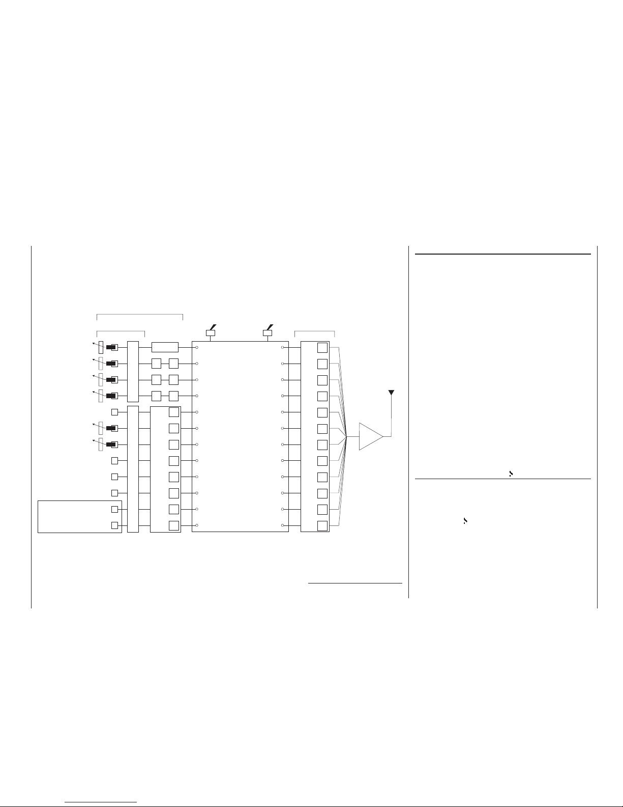
27
Transmitter control switch
It is often extremely desirable to switch a function on
or off automatically at a particular position of another
transmitter control, e.g. at a defi ned position of one of
the dual-axis sticks. Typical examples are switching a
stopwatch on and off to allow you to record the motor run time, lowering landing fl aps automatically, and
many others.
The program of the mc-22s includes a total of four
“switches” of this type. These software switches are
termed “G1 … G4”, and to use one all you have to do
is defi ne the trigger point along the travel of the transmitter control; this is done simply by pressing a button. There are also “inverted switches”, which have
the same function but the reversed direction of effect.
They are therefore termed “G1i … G4i”.
Of course, control switches can also be combined
in any way with the external switches described previously; in this way many more complex problems can
be solved.
This manual includes a range of instructive examples
which make programming as simple as child’s play.
Please refer to the programming examples in the section starting on page 72, 102 and 132.
Fixed switches: FXI and FX
This type of switch switches a function – such as a timer – on permanently (closed fi xed switch) or off permanently (open fi xed switch); alternatively it supplies
a fi xed input signal to a control function, e.g. FXI =
+100% and FX = -100%. For example, a fi xed switch
can be used in fl ight phase programming to switch a
servo or a speed controller between two settings. You
will fi nd another example on page 107.
Defi nition of terms
Control function
Control channel
Aerial
RF
»Servo adjustment«: reverse - centre - travel - limit
mc
-22s programs
For example:
Model type
Helicopter type
Control switch
Auxiliary switch
Phase setting
Phase assignment
Undelayed channel
Wing mixers
Helicopter mixer
Free mixers
MIX active/phase
MIX-only channel
Dual mixer
Two-position switch
or three-position
switch
For switching mixers, auto-
rotation, fl ight phases, …
Function input
Channel 1
curve
DR
DR
DR
EXPO
EXPO
EXPO
Dual-axis stick unit
Dual-axis stick unit
e.g. Optional *
transmitter control 5
Transmitter controls 6
(slider)
Transmitter controls 7
(slider)
e.g. Optional *
transmitter control 8
e.g. Optional *
transmitter control 9
e.g. Optional *
transmitter control 10
Unrestricted assignment
by software
Control assignment 1 … 4Unrestricted transmitter control assignment, inputs 5 … 12
»Control adjust«: offset - travel - time
Transmitter control
Some of the transmitter cont-
rol inputs 5 … 12 are pre-as-
signed in the basic software
programming.
Transmitter control inputs 1 …
4 can be interchanged in the
»Base setup model« menu.
The above transmitter cont-
rols can be assigned to inputs
5 … 12 in any order.
Mixer input
Mixer output
* Optional transmitter controls:
see Appendix, pages 164 - 166
1
2
3
4
5
6
7
8
9
10
11
12
5
6
7
8
9
10
11
12
Page 28
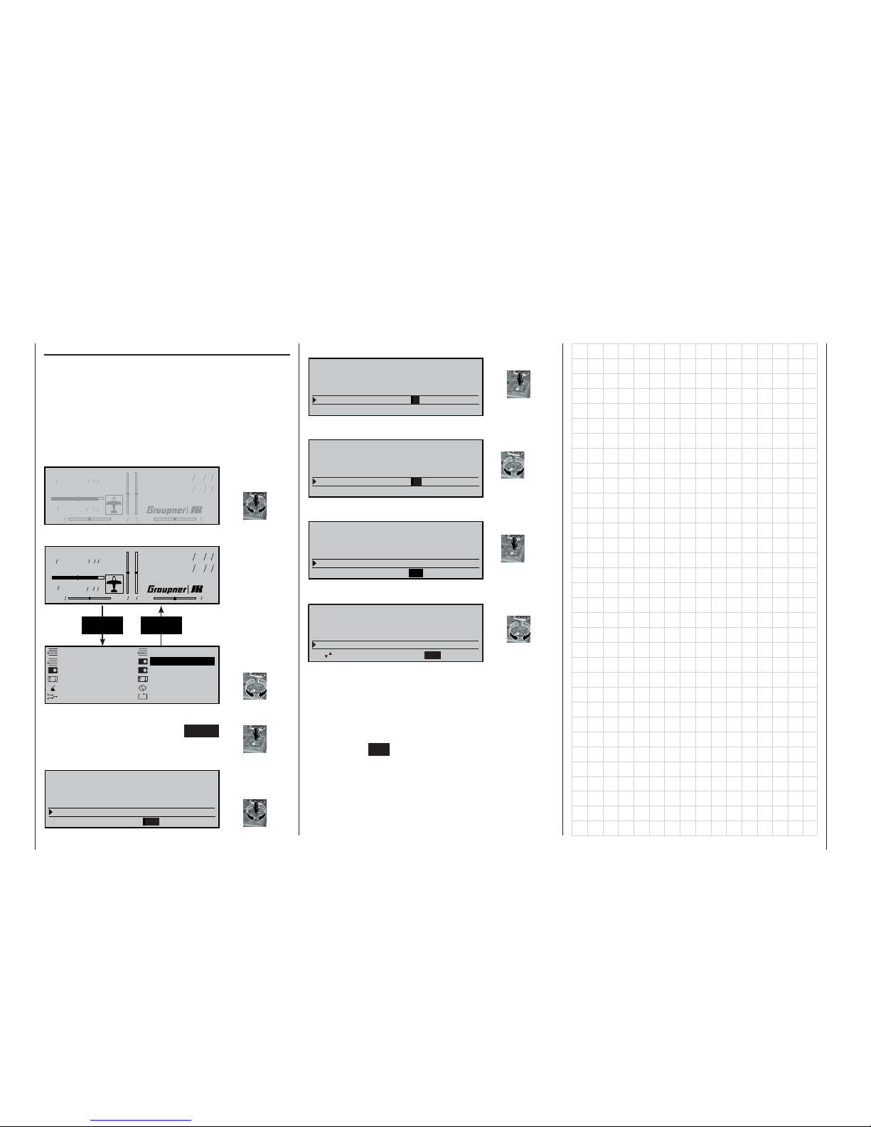
28
Basic operation of the “3-D rotary control”
Screen contrast adjustment, multi-function list, menu settings
Rotary control
Rotary control functions
The basic method of using the rotary control has already been described on page 18. Here we show an
example of using the rotary control in a practical application, to provide a better idea of its functionality.
First switch the transmitter on. Set the transmission
channel (see page 22), and you will move to the basic
screen display.
• Adjusting screen contrast
Press and rotate:
• Select multi-function list
Rotate: (select
menu)
• Menu settings
Press the rotary control (or ENTER)
briefl y to move to a menu.
Now select a line:
Press and rotate:
Call up an input fi eld:
Brief press:
Change a value:
Rotate:
Confi rm input and quit:
Brief press:
Call up next parameter fi eld:
Rotate:
Model name
#01 0:00h C73
H-J Sandbrunner
10.8V
0:00h
0 0 0 0
St wat ch
Flighttm
0 00
0 00
:
:
Model name
#01 0:00h C73
H-J Sandbrunner
10.8V
0:00h
0 0 0 0
St watch
Flighttm
0 00
0 00
:
:
ENTER ESC
Model select Copy / Erase
Suppress codes Base setup model
Model type Servo adjustment
Control adjust Dual Rate / Expo
Switch display Timers
Wing mixers Basic Settings
B A S I C S E T T I N G S , M O D E L
M o d e l n a m e < >
S t i c k m o d e 2
M o d u l a t i o n
P P M 1 8
T r i m s t e p s 4 4 4 4
C H 1 A I L E E L E V R U D D
t
s
B A S I C S E T T I N G S , M O D E L
M o d e l n a m e < >
S t i c k m o d e 2
M o d u l a t i o n
P P M 1 8
T r i m s t e p s
4 4 4 4
C H 1 A I L E E L E V R U D D
t
s
B A S I C S E T T I N G S , M O D E L
M o d e l n a m e < >
S t i c k m o d e 2
M o d u l a t i o n
P P M 1 8
T r i m s t e p s
1 0 4 4 4
C H 1 A I L E E L E V R U D D
t
s
B A S I C S E T T I N G S , M O D E L
M o d e l n a m e < >
S t i c k m o d e 2
M o d u l a t i o n
P P M 1 8
T r i m s t e p s 1 0 4 4 4
C H 1 A I L E E L E V R U D D
t
s
"!3)#3%44).'3-/$%,
-ODELNAME
3TICKMODE
-ODULATION 00-
4RIMSTEPS
#(
!),%%,%625$$
Turn the rotary control to change the rest of the parameter fi elds, in this case CH1, AILE, ELEV, RUDD
(in each case the element which can be changed appears in inverse video, i.e. with a black background),
and press it to move from the selected parameter
fi eld to the change fi eld, etc.
Finally press ESC to return to the multi-function list.
Page 29
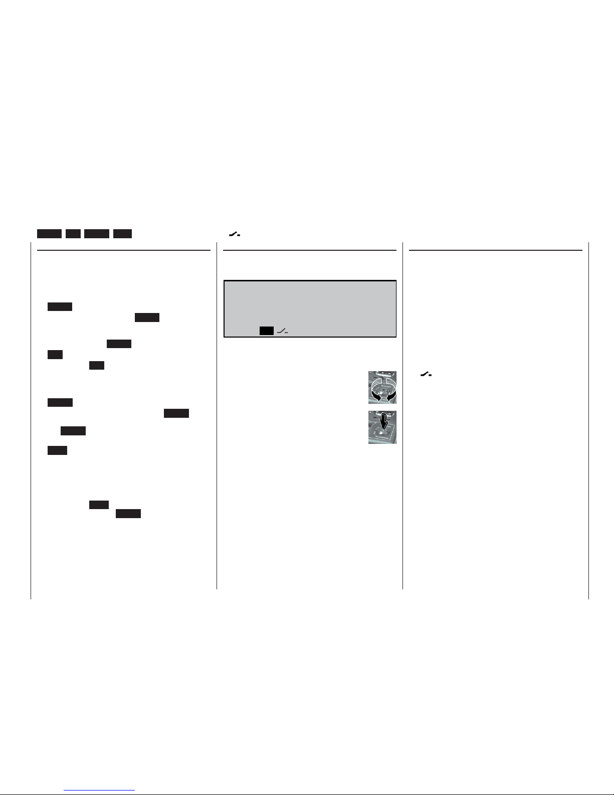
29
Operating buttons
Using the “Data Terminal” LCD screen
Input buttons and function fi elds
ENTER, ESC, CLEAR, HELP, SEL, STO, CLR, SYM, ASY, , E/A, , ENT
The basic method of operating the software
The transmitter is programmed using just four buttons
situated to the left of the screen, in conjunction with
the crucial element: the rotary control (“3D rotary control”).
Input buttons:
• ENTER
the fi rst time you press the ENTER button you
move from the basic screen display to the multi-function menus. You can also call up a selected
menu by pressing ENTER.
• ESC
pressing the ESC button takes you one step back
at the function select stage, and continues to return you through the system until you reach the
basic display.
• CLEAR
at the programming stage, pressing CLEAR re-
sets a changed parameter back to the default value. CLEAR is also used to leaf backwards through the pages within the Help function.
• HELP
at any point in the programming process you can
press this button to call up a concise help text
which informs you how to use the individual menu
in which you are currently located. Within the Help
text you can leaf through the screen pages by
pressing the HELP button again, and leaf through
backwards using the CLEAR button.
In the »Code lock« menu (see page 119) you can
enter a confi dential number which bars access to all
menus. In this case the four input buttons are used in
a different way to that outlined above.
Function fi elds:
In some menus the bottom line of the screen displays
function fi elds which can be called up using the rotary control:
E / A A S Y
S Y M
S E L
S T O C L R E N T
è
The function fi elds which appear on the screen vary
according to the menu you have called up.
Turn the rotary control to switch between
the function fi elds.
Press the rotary control to activate a function fi eld.
Function fi eld functions
• SEL (select):
select this point
• STO (store):
store (e.g. a transmitter control position)
• CLR (clear):
erase (e.g. an input or a reference point on a cur-
ve)
• SYM:
set a symmetrical mixer value
• ASY:
set asymmetrical mixer values
•
:
switch symbol fi eld (assignment of external, fi xed
and control switches)
• E/A:
switches menus on and off
•
:
shifts to second page within a menu (following
menu)
• ENT (enter):
only in the »Code lock« menu; see page 119.
Page 30
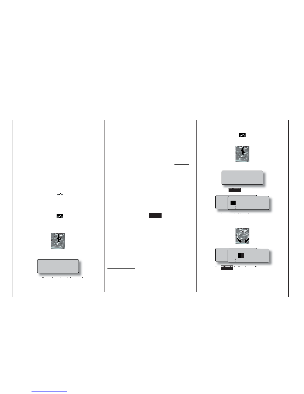
30
Assigning external switches and control switches
Basic procedure, meaning of the fi xed switch “FX”
At many points in the program there is the option of
assigning a switch to a particular function, using an
external switch or a control switch (see below), or
using a switch to select one of two settings, e.g. curve settings, the DUAL RATE / EXPO function, fl ight
phase programming, mixers etc.. In all situations the
mc-22s allows you to assign several functions to one
switch, if you wish.
The process of assigning switches is exactly the
same in all the menus concerned, and we will explain
the basic programming procedure at this point so that
you can concentrate on the special features when
reading the detailed menu descriptions.
A switch symbol appears in the bottom line of the
screen at all programming points where switches can
be assigned:
If you move to this fi eld using the rotary control, the
switch symbol fi eld changes to inverse video (black
background):
This is how you assign an external switch:
1. Brief press on the rotary control
2. The following fi eld appears on the screen:
Simply move the external switch you wish to
use to the “ON” position – regardless of the socket number 0 ... 7 to which the switch is connec-
ted. This completes the assignment process; the
switch concerned (external or control switch) now
appears in the appropriate menu. A switch symbol
adjacent to the switch number indicates the current state of the switch concerned.
Note:
The position to which you eventually move the
switch (in order to assign it) is accepted by the
transmitter as the ON position. For this reason you
should move the external switch to the preferred
OFF position before you activate the switch symbol.
3. Changing the direction of switching
If the switch turns out to work in the wrong direc-
tion, correct it as follows: move the switch to the
desired OFF position, select the switch symbol
once more and assign the switch again, this time
with the direction of switching you prefer.
4. Erasing a switch
Activate the switch symbol as described under
point 2, then press the CLEAR button to erase the
switch.
Using transmitter control switches
For some special functions it may be preferable to
trigger the switching action at a particular (selectable)
position of a stick, slider or rotary knob (termed the
control position), rather than manually using a normal
external switch.
Four switches of this type, termed control switches
G1 ... G4, are available for this purpose. Note that the
number is simply the number of the control switch; it
does not indicate the number of the transmitter control to which it is assigned, i.e. one of the control functions 1 ... 4.
This is how you assign a control switch:
Start by selecting the switch symbol fi eld (inverse video):
1. Brief press on the rotary control
2. The screen now displays the following fi eld:
Now press the ENTER button:
3. Use the rotary control to select the control switch
G1 ... G4 you wish to use, or a software “reversed” control switch G1i ... G4i (i - “inverted”):
4. Press the ENTER button to confi rm your selec-
tion, or press the rotary control briefl y.
Switch assignment
Move desired switch
to ON position
(ext. switch: ENTER)
M o v e d e s i r e d s w i t c h
o r c o n t r o l
( e x t . s w i t c h : E N T E R )
C n t r l / f i x e d s w i t c h
G 1
G 2 G 3 G 4 F X I
F X
G 1 i G 2 i G 3 i G 4 i
M o v e d e s i r e d s w i t c h
o r c o n t r o l
( e x t . s w i t c h : E N T E R )
C n t r l / f i x e d s w i t c h
G 1 G
2 G 3 G 4 F X I
F X
G 1 i G 2 i G 3 i G 4 i
Move desired switch
to ON position
(ext. switch: ENTER)
Page 31

31
Switch assignment
Meaning of the fi xed switch “FX”
The two FX switches which appear in the above list
are known as “fi xed switches”, which switch a function
on permanently …
FXI
or off permanently.
FX
Possible applications are included in example 2 on
page 107.
The two switches can also be used for the transmitter
control inputs in the »Control adjust« menu:
The closed fi xed switch “FXI” generates a fi xed travel
of +100%, the open fi xed switch “FX ” a value of
-100%. Other values can be obtained by changing the
servo travel.
Note:
All switches can also be assigned to multiple
functions. Please take care to avoid assigning several functions to one switch accidentally! We recommend that you take careful note of the switch
functions you have assigned.
5. To erase the control switch:
Press the CLEAR button at the following display:
The control switch must now be assigned to
the control (transmitter control) you wish to
use: 1 ... max. 10. You also have to defi ne the
switching point between ON and OFF or vice versa. Both points are carried out in the »Control
switch« menu; see page 72.
Move desired switch
to ON position
(ext. switch: ENTER)
Page 32

32
Digital trims
Description of function, and Ch1 cut-off trim
Digital trims with visual and audible indicators
Both the dual-axis stick units are fi tted with digital trim
systems. When you give the trim lever a brief push
(one “click”), the neutral position of the stick channel changes by one increment, the size of which you
can select. If you hold the trim lever in one direction,
the trim value changes continuously in the corresponding direction with increasing speed. In the »Base se-
tup model« menu (page 50) you can set the increment per click to any value in the range “1” to “10”.
The screen shows the current trim position and its numerical value.
The degree of trim offset is also “audible”, as the pitch
of the tone changes to refl ect the setting. With a model in fl ight you can fi nd the trim centre position easily without having to look at the screen: If you over-run
the centre position, the trim stays in the centre position for a moment.
The current trim values are automatically stored when
you switch from one model memory to another. The
digital trims are also stored separately for each fl ight
phase within a model memory, with the exception of
the “Ch1” function (Channel 1), which is the throttle /
airbrake trim on a fi xed-wing model.
The Ch1 trim includes another special function which
makes it easy to re-locate the idle throttle setting of
a glowplug motor – provided that you have previously entered “forward” or “back” in the motor line of the
»Model type« menu; see page 52.
1. Fixed-wing models
The Ch1 trim features a special cut-off trim which
is designed for glowplug motors:
You initially use the trim lever in the usual way to
select a reliable idle setting for the motor. If you
now move the Ch1 trim lever towards “motor cutoff” as far as its end-point (i.e. you hold the trim lever at its end-point continuously until the audible
signal ceases), pushing the lever in a single move-
ment, a marker appears on the screen in the last
position. You can now return to the idle setting for
starting the motor simply by pushing the idle lever
once in the direction of “more throttle”.
Notes:
The cut-off trim is disabled if you enter “none” in
the Motor line of the »Model type« menu (see
page 52).
Since this trim function is only effective in the direction of “motor off”, the illustration above will
look different if you reverse the control direction for
the throttle minimum position of the Ch1 stick from
“back” (as set in the picture above) to “forward” in
the “Motor” line of the »Model type« menu.
Of course, you can set the left-hand stick as the
Ch1 stick if you prefer; see the »Base setup mo-
del« menu.
2. Model helicopters
In helicopter mode the Ch1 trim has another fea-
ture in addition to “cut-off trim” as described under
“Fixed-wing models”; this time in conjunction with
the “Throttle limit function”:
While the throttle limit slider is in the bottom half of
its travel, i.e. in the “start-up range”, the Ch1 trim
lever acts as idle trim on the throttle limit.
For more information please read the section en-
titled “Throttle limit” on page 62.
Note:
The Ch1 trim only affects the throttle servo – not
the collective pitch servos – and it works equally
over the full stick travel. Please note that the throttle servo for a helicopter must be connected to receiver output 6 (see “Receiver assignments” on
page 37).
Digital trims
H+
ER
H
3TWATCH
&LIGHTTM
Marker line on screen only if throttle
limit slider is below centre
Marker line indicates last Ch1
trim position (idle setting)
Throttle limit slider
Trim position at which motor stops
E
LLNAME
H+
%IGENTàMER
6
H
3TWATCH
&LIGHTTM
Trim value
Direction indicator
Ch1 trim lever
Current trim position
Last Ch1 trim position
Idle direction
Page 33

33
Digital trims
Page 34

34
Fixed-wing model aircraft
Fixed-wing models
This program provides straightforward, carefully tailored support for conventional models with up to two aileron servos and two fl ap servos, models with V-tail,
fl ying wings and deltas with two elevon (aileron / elevator) servos and two fl ap servos. The vast majority of
power models and gliders belong to the “normal” tail
type with one servo each for elevator, rudder, ailerons
and throttle (or electronic speed controller, or airbrakes on a glider). There is also the special model type
“2Elev.Sv3+8” which provides a means of connecting
two elevator servos to channels 3 and 8.
If the model has a V-tail instead of a standard tail confi guration, you should select the “V-tail” type in the
»Model type« menu, as this mixes together the elevator and rudder functions in the required way, i.e.
each tail control surface is actuated by a separate
servo, and both assume superimposed elevator and
rudder functions.
If your model features two separate aileron servos,
the aileron travels can be set up with differential movement, i.e. the down-travel can be set independently of the up-travel. Finally the program caters for camber-changing fl aps which can be operated by the
transmitter control connected to socket “CH6”.
The “fl ap differential” function can be used to provide
differential travel when the fl aps are programmed to
follow the aileron function.
For deltas and fl ying wings it is easy to set up mixed
elevons, i.e. the aileron and elevator functions can be
carried out via single control surfaces at the trailing
edge of the right and left wing. The program contains
the appropriate mixer functions for the two servos as
standard.
Up to four fl ight phases can be programmed in each
of the thirty model memories (see »Phase settting«
and «Phase assignment« menus). A copy facility is
provided, making the setting of individual fl ight phases much easier (»Copy / Erase« menu).
Two timers are available at all times when fl ying. The
screen also displays the transmitter operating time
and the time which has elapsed for each model memory.
The digital trim positions are stored separately for
each fl ight phase with the exception of the Ch1 trim.
The Ch1 trim provides a simple means of re-locating
the correct idle throttle setting.
“Dual Rate” and “Exponential” can be programmed for
aileron, rudder and elevator, giving two modes of control in each fl ight phase.
As an option, a transmitter control (rotary knob, slider
or switch module) can be assigned to inputs 5 ... 8 separately for each fl ight phase (see »Control adjust«
menu).
In addition to four freely assignable linear mixers,
the program offers two curve mixers (»Free mixers«
menu), two dual mixers (»Dual mixers« menu) and
a fi ve-point curve (»Channel 1 curve«) for channel 1
(throttle / brake).
Depending on the model type you have selected, the
“Wing mixers” menu presents you with a list of predefi ned mixers and coupling functions from which you
can choose:
1. Aileron differential
2. Flap differential
3. Aileron rudder (switchable),
4. Aileron fl ap (switchable)
5. Airbrake elevator (switchable)
6. Airbrake fl ap (switchable)
7. Airbrake aileron (switchable)
8. Elevator fl ap (switchable)
9. Elevator aileron (switchable)
10. Flap elevator (switchable)
11. Flap aileron (switchable)
12. Differential reduction
E
l
e
v
a
t
o
r
Õ
F
l
a
p
F
l
a
p
Õ
E
l
e
v
a
t
o
r
F
l
a
p
Õ
A
i
l
e
r
o
n
A
i
l
e
r
o
n
Õ
F
l
a
p
A
i
l
e
r
o
n
Õ
R
u
d
d
e
r
E
l
e
v
a
t
o
r
Õ
A
i
l
e
r
o
n
left
right
E
l
e
v
a
t
o
r
Õ
F
l
a
p
F
l
a
p
Õ
E
l
e
v
a
t
o
r
A
i
l
e
r
o
n
Õ
R
u
d
d
e
r
A
i
l
e
r
o
n
Õ
F
l
a
p
Airbrake Õ Flap
Airbrake
Õ
Elevator
Airbrake-Function 1
left
right
Rudder/Elevator
V-Tail
E
l
e
v
a
t
o
r
Õ
A
i
l
e
r
o
n
A
i
l
e
r
o
n
Õ
R
u
d
d
e
r
F
l
a
p
Õ
E
l
e
v
a
t
o
r
E
l
e
v
a
t
o
r
Õ
F
l
a
p
A
i
l
e
r
o
n
Õ
F
l
a
p
F
l
a
p
Õ
A
i
l
e
r
o
n
F
l
a
p
Õ
A
i
l
e
r
o
n
A
i
l
e
r
o
n
Õ
F
l
a
p
Airbrake Õ Flap
Airbrake
Õ
Elevato
r
Airbrake Õ Aileron
Page 35
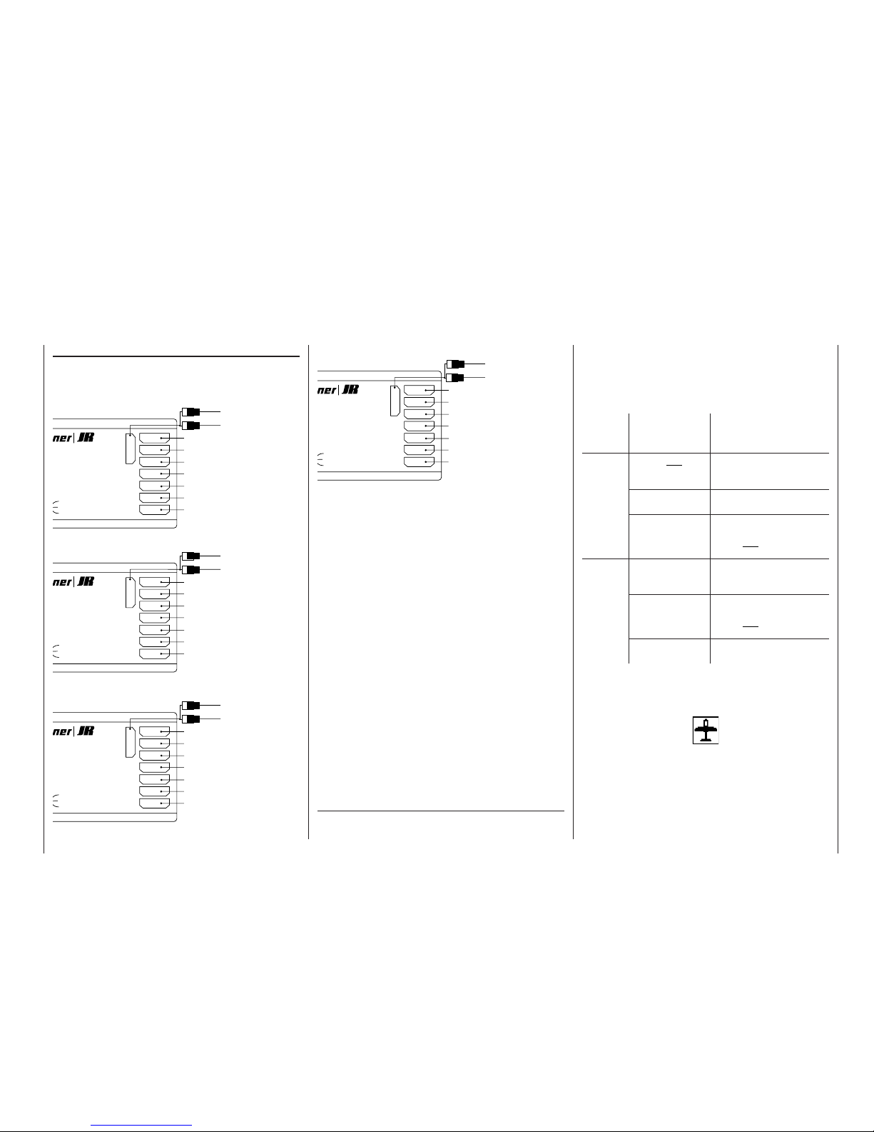
35
Fixed-wing models
Receiver socket sequence
The servos must be connected to the receiver outputs in the following order:
Models with “normal” tail type:
Models with “V-tail”:
Models with “Delta / Flying wing” tail type:
7
6
5
4
3
2
1
8/Batt.
izer-MICRO-SUPERHET
1 6
FM
Best.-Nr.
7052
anal 60-282/182-191
s 35MHz/35MHz-B-Band
Made in Malaysia
S C A N
! #
Receiver battery
Y-lead, Order No. 3936.11 or 3936.32
Auxiliary function
Right fl ap servo
Flap servo or left fl ap servo
Right aileron servo
Rudder servo
Elevator servo
Aileron servo or left aileron servo
Flaps or throttle or speed controller (electric power)
7
6
5
4
3
2
1
8/Batt.
izer-MICRO-SUPERHET
1 6
FM
Best.-Nr.
7052
anal 60-282/182-191
s 35MHz/35MHz-B-Band
Made in Malaysia
S C A N
! #
Receiver battery
Y-lead, Order No. 3936.11 or 3936.32
Auxiliary function
Right fl ap servo
Flap servo or left fl ap servo
Right aileron servo
Right V-tail servo
Left V-tail servo
Aileron servo or left aileron servo
Flaps or throttle or speed controller (electric power)
7
6
5
4
3
2
1
8/Batt.
izer-MICRO-SUPERHET
1 6
FM
Best.-Nr.
7052
anal 60-282/182-191
s 35MHz/35MHz-B-Band
Made in Malaysia
S C A N
! #
Receiver battery
Y-lead, Order No. 3936.11 or 3936.32
Auxiliary function
Right fl ap servo
Left fl ap servo
Auxiliary function
Rudder servo
Right elevon servo
Left elevon servo
Flaps or throttle or speed controller (electric power)
Models with “2 Elev.Sv3+8” tail type:
Outputs not required are simply left unused.
If you are using a GRAUPNER transmitter to control
a model fi tted with a PPM-FM receiving system made
by another manufacturer*, which was formerly fl own
using a different make of transmitter, e.g. when using
the mc-22s for Trainer mode operations, it may be necessary to re-arrange the servo sequence at the receiver outputs. However, an alternative method is to
use the “Receiver output” sub-menu of the »Base
setup model« menu; see page 51. Different methods
of installing servos and control linkages may make it
necessary to reverse the direction of rotation of some
servos when programming. In both cases this is carried out in the »Servo adjustment« menu; see page
56.
7
6
5
4
3
2
1
8/Batt.
izer-MICRO-SUPERHET
1 6
FM
Best.-Nr.
7052
anal 60-282/182-191
s 35MHz/35MHz-B-Band
Made in Malaysia
S C A N
! #
Receiver battery
Y-lead, Order No. 3936.11 or 3936.32
2nd elevator servo
Right fl ap servo
Flap servo or left fl ap servo
Right aileron servo
Rudder servo
Elevator servo
Aileron servo or left aileron servo
Flaps or throttle or speed controller (electric power)
* GRAUPNER does not guarantee that GRAUPNER radio cont-
rol systems will work correctly in conjunction with receiving systems and radio control equipment made by other manufacturers.
As there are several possible combinations of servo
orientation and control surface linkage, you may fi nd
that the direction of rotation of one or more servos is
incorrect.
Use the following table to solve the problem.
Model
type
Servo rota-
ting in wrong
direction
Remedy
V-tail Rudder and ele-
vator reversed
Reverse servos 3 + 4 in
the »Servo adjustment«
menu
Rudder correct,
elevator reversed
Swap over servos 3 + 4 at
the receiver
Elevator correct,
rudder reversed
Reverse servos 3 + 4 in
the »Servo adjustment«
menu, and swap over at
the receiver
Delta,
fl ying
wing
Elevator and ailerons reversed
Reverse servos 2 + 3 in
the »Servo adjustment«
menu
Elevator correct,
ailerons reversed
Reverse servos 2 + 3 in
the »Servo adjustment«
menu, and swap over at
the receiver
Ailerons correct,
elevator reversed
Swap over servos 2 + 3 at
the receiver
All menus which are relevant to fi xed-wing models are
marked with an “aeroplane” symbol in the “Program
descriptions”:
This means that you can easily skip irrelevant menus
when programming a fi xed-wing model aircraft.
Page 36

36
Model helicopters
Model helicopters
Collective
Pitch Curve
Swashplate
Rotation
Roll Õ Throttle
Pitch-Axis Õ Throttle
Channel 1 Õ Throttle
Roll Õ Tail Rotor
Pitch-Axis Õ Tail Rotor
Channel 1 Õ Tail Rotor
C
h
a
n
n
e
l
1
Õ
T
ail
R
o
t
o
r
T
a
i
l
R
o
t
o
r
Õ
T
h
r
o
t
t
l
e
The continued development of model helicopters and
helicopter components, such as gyros, speed governors, rotor blades etc., has led to the current position where helicopters are capable of sophisticated 3D aerobatics. In contrast, the beginner to helicopter
fl ying needs a simple set-up so that he can quickly
get started on the initial stages of hovering practice,
and then gradually work up to more complex models
which exploit all the options provided by the mc-22s.
The helicopter program of the mc-22s can cope with
all current model helicopters equipped with 1 ... 4 servos for collective pitch control.
Each model memory can include three fl ight phases
plus auto-rotation (see »Auxiliary switch«, »Phase
setting« and »Phase assignment« menus).
Four timers are constantly included in the basic
screen display.
The digital trim settings are stored separately for each
fl ight phase. You can return to the correct idle throttle
trim for Ch1 simply by pressing a button.
The transmitter control assignment for inputs 5 ...
8 can also be set separately for each fl ight phase
(»Control adjust« menu).
During the test-fl ying phase the “Copy fl ight phase”
function can be particularly helpful (»Copy / Erase«
menu).
“Dual Rate” and “Exponential” are available for roll,
pitch-axis and tail rotor, and they can be coupled together and programmed to provide two settings in
each fl ight phase.
You can set up four freely assignable linear mixers,
two curve mixers and two dual mixers, and they can
be switched on or off separately in each fl ight phase
in the »MIX active / phase« menu.
Five-point curves are provided for the collective pitch,
throttle and tail rotor mixers, variable separately for
each fl ight phase, giving non-linear mixer characteristics as often required for the roll and pitch-axis functions. Independently of this feature, the control curve
for the Channel 1 stick can also be defi ned using fi ve
points, separately for each fl ight phase; this feature
is not available for fi xed-wing models. These advanced features are not needed by the beginner, who will
usually start simply by setting the hover point to coincide with stick travel centre.
Pre-programmed mixers in the »Helicopter mixer«
menu:
1. Collective pitch curve (with fi ve-point curve)
2. Channel 1 throttle (with fi ve-point curve)
3. Channel 1 tail rotor (with fi ve-point curve
4. Tail rotor throttle (with fi ve-point curve)
5. Roll throttle
6. Roll tail rotor
7. Pitch-axis throttle
8. Pitch-axis tail rotor
9. Gyro suppression
10. Swashplate rotation
The “throttle limit” function (Input 12 in the »Control
adjust« menu) provides an effective means of starting the motor in any fl ight phase. By default the slider
connected to CH7 on the transmitter circuit board is
assigned to input 12, and this control function determines the maximum throttle servo position, i.e. the slider controls the motor over the idle range.
If the slider is moved in the direction of full-throttle,
the programmed throttle curves then take effect.
Page 37

37
Model helicopters
Receiver socket sequence
The servos must be connected to the receiver output
sockets in the following sequence:
Outputs not required are simply left unused.
For more details on the different types of swashplate
please refer to the »Helicopter type« menu described on page 53.
If you are fl ying a model helicopter fi tted with a PPMFM receiver made by another manufacturer*, which
was previously fl own using another make of transmitter, e.g. with the mc-22s for Trainer mode operations,
it may be necessary to re-arrange the receiver servo outputs. However, an alternative method is to use
the “Receiver output” sub-menu of the »Base setup
model« menu; see page 51. Different methods of installing servos and control linkages may make it necessary to reverse the direction of rotation of some
servos when programming. In both cases this is carried out in the »Servo settings« menu; see page 56.
Notes for modellers upgrading from the mc-20:
• Compared with the mc-20, the collective pitch and
throttle servo sockets are interchanged at the receiver; see the table in the left-hand column.
• A standard feature of the mc-20 is a slider for collective pitch trim, connected to the CH6 socket on
the transmitter circuit board. If you want to retain
the slider for collective pitch trim on the mc-22s you
7
6
5
4
3
2
1
8/Batt.
izer-MICRO-SUPERHET
1 6
FM
Best.-Nr.
7052
anal 60-282/182-191
s 35MHz/35MHz-B-Band
Made in Malaysia
S C A N
! #
Receiver battery
Y-lead, Order No. 3936.11 or 3936.32
(Speed governor)
(Gyro gain)
Throttle servo (speed controller: electric motor)
Unused or pitch-axis servo 2
Tail rotor servo (gyro system)
Pitch-axis servo 1
Roll servo 1
Collective pitch or roll servo 2 or pitch-axis
servo 2
will need to set up a suitable mixer in the »Free mixers« menu, e.g. a mixer 8 1, program a sym-
metrical mixer input of around 30%, and assign
transmitter control 6 or 7 to mixer input “8” in the
»Control adjust« menu – depending on the input
to which the slider is connected. This assumes that
the slider is not already in use for another purpose.
However, we also recommend that you de-couple transmitter control 6 or 7 from input 6 or 7 in the
»MIX-only channel« menu, so that control 6 or 7
cannot also operate the associated servo. See example 3 on page 107.
Different methods of installing servos and control linkages may make it necessary to reverse the direction
of rotation of some servos when programming. You
can correct such problems by using the servo reverse
facility located in the »Servo adjustment« menu on
page 56.
All Codes (menus) which are relevant to model helicopters are marked with a “helicopter” symbol in the
“Program descriptions”:
This means that you can easily skip irrelevant menus
when programming a model helicopter.
* GRAUPNER does not guarantee that GRAUPNER radio cont-
rol systems will work correctly in conjunction with receiving systems and radio control equipment made by other manufacturers.
Page 38

38
Brief programming instructions
for all fi xed-wing and helicopter programs
Brief programming instructions
Menu
Menu
Display
Display
Description of program expansions and operating notes
Description of program expansions and operating notes
Page
Page
Model memories
Model memories
• • Model select Selects a free or occupied model memory 1 ... 30 47
• • Copy / Erase Erase a model memory
Copy one model memory to another memory
Copy from / to mc-22s, to a PC, or between an mc-22s, an mc-22 and / or an mx-22
Copy individual fl ight phases within one model memory
Back-up all models to a PC
47
• • Suppress codes Suppress functions from the multi-function select list within a memory; used for settings which are not to be altered, or which are not required.
Note:
By default some menus are already suppressed. If necessary, move to the »Basic settings« menu and switch on
“Expert mode”, which activates all available menus, BEFORE you set up a new model.
49
Basic settings / Servos
Basic settings / Servos
• • Basic setup model Model name: max. 11 characters (letters, numbers, special symbols). Characters selected using rotary
control.
Stick modes, fi xed-wing model aircraft:
1: Elevator, rudder: left and throttle/brake, aileron: right
2: Throttle/brake, rudder: left and aileron, elevator: right
3: Aileron, elevator: left and throttle/brake, rudder: right
4: Throttle/brake, aileron: left and elevator, rudder: right
Stick modes, helicopter:
1: Pitch-axis, tail rotor: left and motor/coll. pitch, roll: right
2: Motor/coll. pitch, tail rot: left and pitch-axis, roll: right
3: Pitch-axis, roll: left and motor/coll. pitch, tail rotor: right
4: Motor/coll. pitch, roll: left and pitch-axis, tail rotor: right
Modulation: PCM20 for all “mc” or “DS mc” type PCM receivers (512 steps)
SPCM20 for all “smc” type SPCM receivers (1024 steps)
PPM18 for all PPM-FM receivers to date except DS 24 FM
PPM24 for “DS 24 FM” PPM FM receiver
Trim increment: Setting of increment size for all four digital trim levers, range 1 to 10
Receiver output: Interchange the receiver outputs. Swapping the outputs does not affect any other coupling
and mixer functions, servo settings etc., i.e. you do not have to adjust these settings if you
50
Page 39

39
Brief programming instructions
Menu
Menu
Display
Display
Description of program expansions and operating notes
Description of program expansions and operating notes
Page
Page
interchange the outputs.
Exception: Fail-Safe is always defi ned with reference to the receiver sockets.
• Model type Motor: Direction of effect of Ch1 function, throttle minimum “back”, “forward” or “none”. The Ch1
trim acts only “back”, “forward” or over the full range respectively.
Tail type Servo count
„normal“
“V-tail”
“Delta / fl ying wing”
„2 Elev. Sv 3+8“
Optionally up to two aileron servos and up to two fl ap servos
Optionally up to two aileron servos and two fl ap servos
Two elevon servos and up to two fl ap servos
Two elevator servos, plus optionally up to two aileron servos and two fl ap servos
Brake: The wing mixers “brake 5 aileron”, “brake 6 fl ap” and “brake 3 elevator” can opti-
onally be controlled by a transmitter control connected to “input” 1, 8 or 9. Variable mixer
neutral point (offset). If the neutral point is not set at the end of travel, the remaining travel
is a dead zone.
52
• Helicopter type Swashplate type: Select the number of servos (1 ... 4) for collective pitch
Rotor direction: “right” (clockwise) or “left” (anti-clockwise) as seen from above
Coll. pitch min.: Minimum collective pitch angle, channel 1 control “forward” or “back”, see also »Basic
settings« menu.
Expo throttle limit: “Throttle limit” can be set to exponential in »Control adjust« menu.
53
• • Servo adjustment Servo direction: Left or right
Neutral setting: Offset centre point within range -125% to +125%
Servo travel: Symmetrical or asymmetrical, range 0 to 150%
Servo travel limit: Symmetrical or asymmetrical, range 0 to 150%. Typical application: if servo travel is me-
chanically restricted.
56
Transmitter controls
Transmitter controls
• Control adjust Assignment and de-coupling (display = “free”) of transmitter controls (rotary control, sliders, switch modules) 5
to 10. Inputs 5 ... 8 are programmable separately for each fl ight phase. External switches, control switches or the
fi xed switch “FX” can also be assigned if required. Note: two external switches at one input correspond to the
function of the GRAUPNER 2-channel switch module, Order No. 4151 or 4151.1.
Travel: Variable control travel, symmetrical or asymmetrical between -125% and +125%; direction of control’s
effect can also be reversed.
Offset: The centre point of the transmitter control can be offset within the range -125% to +125%
Time: Symmetrical or asymmetrical reduction of transmitter control transit speed. Available range: 0 ... 9.9
sec., e.g. for scale processes, “soft” motor acceleration, etc..
58
Page 40

40
Brief programming instructions
Menu
Menu
Display
Display
Description of program expansions and operating notes
Description of program expansions and operating notes
Page
Page
• Control adjust Assignment and de-coupling (display = “free”) of transmitter controls (rotary control, sliders, switch modules) 5
to 10. Inputs 5 ... 8 are programmable separately for each fl ight phase. External switches, control switches or the
fi xed switch “FX” can also be assigned if required. Note: two external switches at one input correspond to the
function of the GRAUPNER 2-channel switch module, Order No. 4151 or 4151.1.
Note:
Input 12 is reserved for the “throttle limit” function. The assigned transmitter control only operates the throttle servo in addition to servo 12. For this reason servo 12 can only be accessed via a mixer using the »MIX-only chan-
nel« function. Application of “throttle limit”: see page 62. Transmitter control 7 (slider as standard) is assigned to
this in the software.
Travel: Variable control travel, symmetrical or asymmetrical between -125% and +125%; direction of control’s
effect can also be reversed.
Offset: The centre point of the transmitter control can be offset within the range -125% to +125%.
Time: Symmetrical or asymmetrical reduction of transmitter control transit speed. Available range: 0 ... 9.9
sec., e.g. for scale processes, “soft” motor acceleration, etc..
60
• • Dual Rate / Expo Affects control functions aileron, elevator and rudder, or roll, pitch-axis and tail rotor. DUAL RATE and EXPO are
programmable separately for each fl ight phase.
DUAL RATE: Altered control travel within the range 0 to 125% of normal control travel. Switch can be assigned,
enabling user to switch between two settings in fl ight.
EXPO: Sets an exponential control curve without changing total travel. Variable rate of progression within
the range -100% to +100%; optionally can be switched between two settings using external
switch or control switch.
Asymmetrical DUAL RATE or EXPO curves can be programmed if the control switch is set to the stick centre position in the »Control switch« menu, and the stick is moved in the corresponding direction.
64/66
• • Channel 1 curve Defi nes the characteristic curve of the throttle / airbrake function or motor / collective pitch stick:
The momentary stick position of the transmitter control for the input channel is indicated on the screen by a verti-
cal bar. (“Input” shows the associated % value. “Output” gives the corresponding value of the control output). Between the two extreme points “L” (low) and “H” (high) up to three additional curve reference points can be defi ned:
all three points can be positioned along the control travel when “Point ” appears on the screen. Set the desired
“point” value in the inverse-video fi eld using the rotary control, press rotary control to confi rm. The points are automatically numbered sequentially from 1 to 3. To re-position points L, 1, 2, 3 or H subsequently, move the associated transmitter control to select the appropriate reference point, then press the CLEAR button to erase points 1
... 3. Pressing the left-hand ENTER button switches a curve-rounding algorithm “on” and “off”. With model heli copters this function can be programmed separately for each fl ight phase.
68/70
Brief programming instructions
for all fi xed-wing and helicopter programs
Page 41

41
Menu
Menu
Display
Display
Description of program expansions and operating notes
Description of program expansions and operating notes
Page
Page
Switches
Switches
• • Switch display When an external switch or control switch is operated, this displays the associated switch number and switch position.
72
• • Control switch Assign the control switches 1 ... 4 to the transmitter controls 1 ... 10. Pressing STO (press the rotary control) in column 3 stores the current control position as the switching point. Reverse the switching direction in column 4, and
assign a switch to activate (and disable) a control switch in column 5. Column 6 displays the switch status.
72
• Auxiliary switch Auto-rotation: a switch assigned to this function activates the Auto-rotation fl ight phase. It has priority
over all other fl ight phase switches and the Auto-rotation Ch1 position switch.
Auto-rotation Ch1 Pos.: Alternative auto-rotation switch: defi nes a switching point on the Ch1 stick, can be activa-
ted using STO. External switch required! For more details see »Phase setting« menu.
75
Flight phases
Flight phases
• Phase setting Name: In the »Phase assignment« menu names from a list are assigned to up to four phases (normal,
launch, ...), according to the position of the fl ight phase switches. The names are shown in the
basic display and in all programs which are fl ight phase-specifi c.
Transition time: It is advisable to set a transition time at this point (0 ... 9.9 sec) to avoid abrupt changes between
different fl ight phases; this provides a “soft” transition.
Meaning of symbols in right-hand column:
Indicates the phase assigned to each switch position. Phase 1 by default if no other switches are
assigned, or if all phase switches are at the base position.
+
A switch position is provided for this phase in the »Phase setting« menu.
–
The phase is not in use.
78
• Phase setting In contrast to »Phase setting« for fi xed-wing models, the name of the auto-rotation phase cannot be changed.
This fl ight phase can be activated if a switch is defi ned in the »Auxiliary switch« menu. For more information see
the »Phase assignment« menu.
Transition time: It is advisable to set a transition time at this point (0 ... 9.9 sec) to avoid abrupt changes between
different fl ight phases; this provides a “soft” transition. If auto-rotation is selected, the switch
takes place without any delay; any set delay only takes effect when you quit auto-rotation.
Meaning of symbols in right-hand column: see »Phase setting« menu for fi xed-wing model
79
• • Phase assignment Each of the four (fi xed-wing model) or three (model helicopter) available fl ight phases can be assigned to any
combination of up to four switches; the phases can be assigned names in the »Phase setting« menu. In the
basic setting all switches always generate “Phase 1”; the same applies to non-assigned switch combinations.
Priority of the switch assigned under “A”:
The fl ight phase assigned to this switch has precedence over the fl ight phase switch positions “B”, “C” and “D”.
80
Brief programming instructions
Page 42

42
Menu
Menu
Display
Display
Description of program expansions and operating notes
Description of program expansions and operating notes
Page
Page
• • Undelayed channel The delay when a new fl ight phase is selected can be switched off for individual channels, separately for each
fl ight phase. Examples: motor OFF with electric models, activating and disabling heading lock with gyro systems.
81
Timers
Timers
• • Timers “Model time”: Reset with brief press on the rotary control when the CLR fi eld is active (timer switchable).
“Battery time”: Automatic reset when battery is recharged; can also be reset by pressing CLR.
“Stopwatch”: The stopwatch is switched on and off by means of the switch assigned on the right of the screen.
Pressing CLEAR in the basic display resets the stopwatch to zero, but only if the timing process
has already been halted.
“Flight timer“: The fl ight timer is switched on via the switch assigned on the right. Operate the same switch and
press ESC at the basic display to stop the timer; CLEAR resets it to zero.
“Timer” column: Preset 0:00 means count-up timer; time preset via rotary control (maximum 180 min 59 sec) ge-
nerates count-down timer (fl ashing colon (:) in the basic display).
“Alarm” column: Time and sequence of the warning sounds until the alarm timer passes through zero (max. 90
sec.).
82
Mixers
Mixers
• Wing mixers Number of available mixers varies according to »Model type« menu: aileron differential, fl ap differential, aileron 2
4 rudder, aileron 2 7 fl aps, brake 3 elevator, brake 6 fl ap, brake 5 aileron, elevator 3 6 fl aps, ele-
vator 3 5 aileron, fl aps 6 3 elevator, fl aps 6 5 aileron and differential reduction. All mixers: the mixer ra-
tio can be varied within the range -150% and +150%, separately for each fl ight phase. All wing mixers with fl ap or
elevator inputs can also be programmed separately for each side of neutral. The neutral point (offset) of the “aileron, elevator, fl ap NN” mixers is the zero point of the transmitter control; the neutral point (offset) of the “brake
NN” mixer can be programmed in the »Model type« menu.
All mixers are switchable.
84
• Helicopter mixer Programming separately for each fl ight phase:
a) Non-linear fi ve-point curves for: collective pitch, channel 1 throttle and channel 1 tail rotor; adjus-
ted as in »Channel 1 curve« menu, and
b) linear mixer ratios (0 ... 100%) for the following mixers: tail rotor throttle, roll throttle, roll tail ro-
tor, pitch-axis throttle and pitch-axis tail rotor.
Gyro suppression: Suppression of gyro effect through tail rotor defl ection (0 ... 199%), variable separate-
ly for each fl ight phase, dependent on tail rotor stick position. Programmed values above 100% produce full suppression before full tail rotor defl ection. Also available in the
auto-rotation phase.
Swashplate rotation: (Virtual) rotation of the swashplate in either direction (-90° ... +90°).
The following mixers are available in the auto-rotation phase:
90
Brief programming instructions
Brief programming instructions
for all fi xed-wing and helicopter programs
Page 43

43
Menu
Menu
Display
Display
Description of program expansions and operating notes
Description of program expansions and operating notes
Page
Page
non-linear fi ve-point collective pitch curve, AR throttle position (-125% ... +125%) and
tail rotor offset (AR), gyro suppression and swashplate rotation.
• • Free mixers Select linear mixer 1 ... 4 or curve mixer 5 or 6 with the rotary control pressed in. Defi ne mixer input (any control
function) in “from / to” column; select “from” and output “to” using associated SEL function and rotary control. If a
constant control function is required as input, e.g. motor ON / OFF, then select letter “S” in the “from” column (corresponds to DUMMY mixer in the mc-20), and assign mixer switch in column 4. Include preceding mixers (symbol
“”) and / or trim (“Tr”) of stick 1 ... 4, after setting mixer input in the “Type” column. Select corresponding symbol
“”, “Tr” or “Tr” using rotary control. An (optional) switch can be assigned to any mixer.
Setting mixer ratio and direction with linear mixers:
switch to “Setup” column on the screen page with brief press on rotary control. Select ASY or SYM and set mixer
ratio within the range 0 to +/-150% using the rotary control. To set asymmetrical values, select the side of neutral
using the input channel (vertical line on graph), or by operating the switch in the case of the switched channel “S”.
Setting non-linear mixer curves with curve mixers 5 and 6:
three additional reference points can be defi ned between the two end-points “L” (low) and “H” (high). Basic operating instructions: see »Channel 1 curve« menu on page 68 / 70.
Shifting the offset point (mixer neutral point):
use the transmitter control to move the bar in the graph to the appropriate position, select STO and press the ro-
tary control briefl y. Press the bottom CLR fi eld to move the offset point back to centre.
Notes:
DUAL RATE may limit the offset range of the vertical line!
Mixers may be suppressed in the »MIX active / phase« menu!
102
• • MIX active / phase The mixers 1 ... 6 can be disabled separately for each fl ight phase. In the »Free mixers« menu they are then sup-
pressed separately for each fl ight phase!
108
• • Mix-only channel This function separates the link between transmitter control 1 ... 10 and the associated servo, i.e. the control only
affects the relevant channel as a mixer input. In this case the de-coupled servo is only accessible via a mixer.
108
• • Dual mixer Two mixers designed for coupling two channels in such a way that they work in the same direction and in opposed
directions. Example: camber-changing fl aps (receiver outputs 8 and 9) with aileron function: defi ne dual mix „ 8
, 9 “. In the »Control adjust« menu assign a (free) transmitter control, e.g. control 7, to input 8 for the fl ap
function, and in the »Free mixers« menu defi ne the mixer „AIL 9“ to provide an aileron function. If necessa-
ry reverse the direction of rotation in the »Servo adjustment« menu, and set the required aileron differential (0 ...
100%) in the last column “Diff”. Also suitable for other applications, e.g. differential rudder defl ection with a V-tail.
In this case “EL” is defi ned as a same-direction mixer: EL , and “RU” as an opposed mixer:, RU “, Please note that in this case the tail type must be entered as “normal” in the »Model type« menu!
110
Brief programming instructions
Page 44

44
Menu
Menu
Display
Display
Description of program expansions and operating notes
Description of program expansions and operating notes
Page
Page
• Swashplate mixer Mixer ratios for collective pitch, roll and pitch-axis are separately variable (-100% ... +100%), with the exception of
helicopters with only one collective pitch servo. CLEAR resets changed values to 61%.
Important:
Ensure that servos are not mechanically obstructed if you set large values.
111
Auxiliary functions
Auxiliary functions
• • Fail-safe adjust In PCM20 mode:
„Time“: all servos to “hold” mode, or enter a delay time (1, 0.5 or 0.25 sec.) using rotary control, after
which servos 9 and 10 take up the neutral position, and servos 1 ... 8 take up a position defi nable
using STO.
“Battery F.S.”: three possible servo positions can be selected (-75%, 0%, +75%, plus “off”) for servo 1 in fi xed-
wing models and model helicopters.
112
In SPCM20 mode:
Servos 1 ... 8 can be programmed to hold-mode or position mode. Save selected position using STO. Servos 9
and 10 remain in hold mode.
114
• • Teacher/pupil After assigning a switch (preferably a momentary switch or kick-button), control functions 1 ... 8 can be transferred
to a Pupil transmitter. All model programming is carried out at the Teacher transmitter. The pupil transmitter’s control functions must affect the control channels, i.e. the receiver outputs, directly, without any mixers or other settings being involved. The modulation of the Pupil transmitter must be set to PPM! Only stick mode, throttle / collective pitch reverse and idle trim should be set up to suit the pupil’s preferences.
115
Global functions
Global functions
• • Basic settings Owner’s name: max. 15 characters (letters, numbers, special symbols). Use rotary control to select
characters from the symbol table on the second screen page.
Preset stick mode: the stick mode selected at this point is adopted as standard for all new model memo-
ries.
Preset modulation: PCM20 for all “mc” or “DS mc” type PCM receivers (512 steps)
SPCM20 for all “smc” type SPCM receivers (1024 steps)
PPM18 for all PPM-FM receivers to date except DS 24 FM
PPM24 for “DS 24 FM” PPM FM receiver
Expert mode: „no“: some menus are suppressed in the multi-function list when a new model is set up;
simplifi es programming for the beginner. Suppression of menus can be reversed in the
»Suppress Codes« menu if desired.
“yes” all mc-22s menus are accessible when a new model is set up.
Preset coll. pitch min.: Defi nes the collective pitch minimum position of the Ch1 stick – “forward” or “back”.
117
Brief programming instructions
Brief programming instructions
for all fi xed-wing and helicopter programs
Page 45

45
Menu
Menu
Display
Display
Description of program expansions and operating notes
Description of program expansions and operating notes
Page
Page
Note:
the presets for “stick mode”, “modulation” and “collective pitch min.” are automatically adopted when you call up a
model memory, but can then be changed separately for that memory in the »Base setup model« menu, if preferred.
• • Servo display The servo outputs can be checked on-screen, taking into account all coupling and mixer functions etc. when you
operate the corresponding transmitter control (useful aid when programming).
118
• • Code lock A four-character code number can be entered using the four side buttons, or erased with a short press of the rotary control (CLR) and subsequently corrected. Confi rm by pressing the ENTER button. When you switch the mc22s on again access to the multi-function menu remains barred until you enter the correct code.
119
Brief programming instructions
Page 46

46
Detailed description of programming
Reserving a new memory
If you have already read through to this point in the manual you will undoubtedly have already made your fi rst
attempt at programming the system. Even so, it is important to describe each menu here in detail, to ensure that you have comprehensive instructions for each application you are likely to encounter. In this section we
start with setting up a “free” model memory prior to “programming” a new model:
Program description
Basic transmitter display
The fi rst steps should be to select the menu language
and then select a transmission channel, as described
on pages 21 and 22. Adjust the screen contrast if necessary by pressing and turning the rotary control.
From the basic display press ENTER to shift to the
“Multi-function menu”. You can return to the basic
screen at any time by pressing ESC.
If necessary select the »Model select« menu from
the list using the rotary control.
Note:
If the expert mode has been set to “no” in the
»Basic settings« menu, you will only see a limited
selection of menus at this point. The »Fail-Safe«
menu only appears if the transmitter is set to
“PCM20” or “SPCM20” transmission mode.
Now press ENTER or the rotary control to shift to the
»Model select« menu.
The model memories marked „free“ are
not yet in use. Memories which are already occupied
appear with the model name at the appropriate point,
together with the type of modulation and the model
operating time. The model name is the one you have
entered in the »Base setup model« menu (page 50).
Use the rotary control to select one of the free model memories 1 to 30, then press ENTER or the rotary control.
You are now invited to defi ne the basic model type,
i.e. either “fi xed-wing” or “helicopter”.
Use the rotary control to select the appropriate type,
then press the rotary control or the ENTER button
to confi rm your choice. The screen switches back to
the basic display: the model memory is now reserved.
Changing to another model type for this model memory is now only possible if you fi rst erase the model
memory (»Copy / Erase« menu, page 47).
Caution:
• All the transmitter’s functions are barred, and the
transmitter does not broadcast a signal to the servos, until you confi rm the model type you have selected. If you switch off the transmitter before you
set the model type, the screen automatically reverts to the screen shown at the bottom when turned on again. You must always defi ne a model
type!
• If the warning ...
… appears on the screen, move the throttle stick
back in the direction of idle.
Note:
The appearance of this warning also depends on
the settings you have made in the “Motor” line of
the »Model type« menu (see page 52). Select
“none” if the motor is not powered. The warning is
then disabled.
• If the message ...
... appears on the screen, please read the section
on the »Fail-safe« menu on pages 112 / 114.
The following description of the menus follows the sequence of the multi-function menu list.
ENTER ESC
Model name
#01 0:00h C73
H-J Sandbrunner
10.8V
0:00h
0 0 0 0
St watch
Flighttm
0 00
0 00
:
:
Model select Copy / Erase
Suppress codes Base setup model
Model type Servo adjustment
Control adjust Dual Rate / Expo
Switch display Timers
Wing mixers Basic settings
0 1 C U M U L U S 9 7 S P C M 2 0 1 : 2 5 h
0 2 L a s e r P C M 2 0 2 : 4 5 h
0 3 D V 2 0 K A T A N A
P P M 1 8 5 : 2 6
h
0 4 M E G A S T A R
S P C M 2 0 8 : 3 1 h
0 5
V V V
f r e e
V V V
0 6
V V V
f r e e
V V V
S e l e c t m o d e l t y p e ( f r e e m o d e l m e m o r y )
ENTER ESC
ENTER
Thr
too
high!
Fail Safe
setup
Page 47

47
Model select
Model select 1 … 30
Copy / Erase
Model copy and fl ight phase copy function
0 1 C U M U L U S 9 7 S P C M 2 0 1 : 2 5 h
0 2 L a s e r P C M 2 0 2 : 4 5 h
0 3 D V 2 0 K A T A N A
P P M 1 8 5 : 2 6
h
0 4 M E G A S T A R
S P C M 2 0 8 : 3 1 h
0 5
V V V
f r e e
V V V
0 6
V V V
f r e e
V V V
The transmitter can store up to thirty complete sets
of model settings, including the digital trim values set
by the four trim levers. The trims are automatically
stored, which means that the settings you have carefully established through test-fl ying are not lost when
you swap models.
If you have entered a model name in the »Base se-
tup model« menu (page 50), the name appears after the model number, together with the model type
in pictogram form, the type of modulation and the
model’s operating time.
Use the rotary control to select from the list the model
you wish to use. Confi rm your selection by pressing
the rotary control, or press ENTER. Pressing ESC
takes you back without switching models.
Notes:
• If the warning message “Throttle too high” appears
when you switch models, the throttle stick “Ch1” is
set towards full throttle, and should be returned to
idle.
• If the message “Fail-Safe setup” appears when you
switch models, you should check your Fail-Safe
settings. This only applies if the transmitter is set to
PCM20 or SPCM20 transmission mode.
• If the battery voltage is too low, it may not be pos-
sible to switch model memories for safety reasons.
In this case the screen displays this message:
E r a s e m o d e l = >
C o p y m o d e l
®
m o d e l = >
C o p y M C 2 2
®
e x t e r n a l = >
C o p y e x t e r n a l
®
M C 2 2 = >
C o p y f l i g h t p h a s e = >
S e c u r e a l l m o d e l s
®
P C = >
t
s
This menu is used to:
• erase a model memory;
• copy internally from one model memory to another;
• copy a model memory from one mc-22s transmitter to another, from the mc-22s to the mc-22 or
mx-22, and from the mc-22s to an industry-standard PC;
• copy individual fl ight phases within one and the
same model memory.
• back up the data contained in all the model memories to a compatible PC.
To connect the transmitter to a PC you will need the
PC interface mc-22(s) / PC set, Order No. 4182. This
is an optional accessory which is connected to the
interface distributor (supplied in the set), in order to
transfer model data to the PC, to back up the data on
diskette or hard disc, and – if necessary – to load it
back into the transmitter (or another transmitter). Full
details are included in the set (the PC interface lead
and interface distributor are also available separately; see Appendix). To transfer data between two mc22s transmitters, both transmitters must be fi tted with
the mc-22(s) interface distributor, Order No. 4182.3.
You will also need the copy lead, Order No. 4179.2, to
make the actual transfer.
Caution – essential information:
Be sure to connect the PC or the second transmitter to your mc-22s using the interface or copy lead before you switch the mc-22s transmitter on. When the process is completed, switch the transmitter(s) off
before you disconnect the lead!
Program description: Model memories
Copy lead
Order No. 4179.2
mc-22(s) mc-22(s) or mx-22
mc-22(s) mx-22
OR
PC interface lead
Order No. 4182.9
(see notes on page 163/164)
Not currently possible
Battery voltage too low
Page 48

48
First select the desired option with the rotary control
pressed in, then call it up by pressing ENTER or the
rotary control:
“Erase model”
S e l e c t m o d e l t o b e e r a s e d :
0 1 C U M U L U S 9 7 S P C M 2 0 1 : 2 5 h
0 2 L a s e r P C M 2 0 2 : 4 5 h
0 3 D V 2 0 K A T A N A
P P M 1 8 5 : 2 6
h
0 4 M E G A S T A R
S P C M 2 0 8 : 3 1 h
0 5
V V V
f r e e
V V V
Select the model to be erased using the rotary control. Pressing ESC returns you to the previous screen
page. Press ENTER or the rotary control to shift to
the next screen page:
M o d e l r e a l l y
0 1 C U M U L U S 9 7
t o b e e r a s e d ?
N O Y E S
Select “NO” or “YES” using the rotary control and
confi rm your choice by pressing ENTER or the rotary control.
Caution:
All the data stored in the selected model memory
is erased. The erasure process is irrevocable.
If you erase the currently active model memory in the
basic display, you will be required to defi ne the model
type “Heli” or “fi xed-wing” immediately. However, if you
erase a non-active model memory, then the message
„free“ appears in the Model select menu.
Program description: Model memories
“Copy model model”
C o p y f r o m m o d e l :
0 1 C U M U L U S 9 7 S P C M 2 0 1 : 2 5 h
0 2 L a s e r P C M 2 0 2 : 4 5 h
0 3 D V 2 0 K A T A N A
P P M 1 8 5 : 2 6
h
0 4 M E G A S T A R
S P C M 2 0 8 : 3 1 h
0 5
V V V
f r e e
V V V
Select the model to be copied in the “Copy from model” window, and confi rm by pressing ENTER or the
rotary control. A further window “Copy to model” appears, where you have to enter the destination memory and confi rm your choice, or interrupt the process by pressing ESC. A model memory which is already occupied can be overwritten. In the interests
of safety you have to confi rm the copy process once
more.
M o d e l r e a l l y
0 3 D V 2 0 K A T A N A 0 6
V V V
f r e e
V V V
t o b e c o p i e d ?
N O Y E S
t
“Copy mc22 external”
Select the model memory in the “Copy from model”
window, then confi rm the copy process to a PC or a
compatible transmitter (mc-22, mc-22s, mx-22).
M o d e l r e a l l y
0 2 L a s e r
b e c o p i e d t o P C o r o t h e r t r a n s m i t t e r ?
N O Y E S
The progress of the copy process is indicated by a
horizontal bar.
“Copy external mc22s”
Select the destination memory in the “Copy to model”
window, and confi rm the input as already described.
Once again, you are required to confi rm the copy process from a PC or from another transmitter:
M o d e l r e a l l y
0 5 M E G A S T A R
b e l o a d e d f r o m P C o r o t h e r t r a n s m i t t e r ?
N O Y E S
The transfer process then has to be initiated from the
second transmitter or the PC.
Note:
If the transmitter is not connected to a PC or another
transmitter, you must interrupt the copy process by
switching off the receiving transmitter, then switching
it on again.
“Copy fl ight phase”
C o p y f r o m p h a s e :
1 N
o r m a l 2 L a u n c h
3 4
In the “Copy from phase” menu, use the rotary control
to select the fl ight phase 1 ... 4 (fi xed-wing model or
helicopter) to be copied, confi rm your choice by pressing ENTER or the rotary control, then select the destination in the new “Copy to phase” window and confi rm your choice. For safety’s sake you will be invited
to confi rm your choice once more.
Page 49

49
“Back-up all models PC”
m u s t a l l m o d e l s b e
s a v e d i n a f i l e o n P C ?
N O
Y E S
In this case all occupied model memories are automatically transferred to the PC in sequence for backing-up, in contrast to the “Copy mc22 external”
command.
Note:
If the transmitter battery voltage is too low, the transmitter blocks all copy and erase functions in the interests of safety. The following message then appears
on the screen:
E r a s e m o d e l = >
C o p y m o d e l
®
m o d e l = >
C o p y M X 2 2
®
e x t e r n a l = >
C o p y e x t e r n a l
®
M X 2 2 = >
C o p y f l i g h t p h a s e = >
S e c u r e a l l m o d e l s
®
P C = >
t
Not currently possible
Battery voltage too low
Suppress Codes
Suppressing Codes from the multi-function list
-ODELSELECT #OPY%RASE
"ASESETUPMODEL -ODELTYPE
3ERVOADJUSTMENT #ONTROLADJUST
$UAL2ATE%XPO #HANNELCURVE
3WITCHDISPLAY #ONTROLSWITCH
3UPPRESS
4/'
In this menu you can suppress any functions in the
multi-function list which are not required for the currently active model, or which must not be changed.
For example, if you are programming different fl ight
phases, it is advisable to suppress all global settings
such as modulation, stick mode, servo settings etc..
The multi-function list can then be restricted to just a
few menus, and the function select list becomes easier to read. Suppressing the menus does not disable
those functions; it just means that they can no longer
be accessed directly.
Select the function to be suppressed using the rotary control, then press the rotary control briefl y to suppress it, or re-activate it if already suppressed.
Tip:
If you do not wish to use a program block at all, we
recommend for safety’s sake that you remove the
»Code lock« menu from the multi-function list using
the »Suppress codes« menu, otherwise it would be
relatively easy for an unauthorised person to enter a
secret code number, which would block your access
to the multi-function list.
Caution:
In the transmitter’s default state the expert mode is
set to “no” in the »Basic settings« menu. This means
that some menu points are suppressed as standard.
If you wish to have all menu points available when
you call up a new model memory, you should fi rst set
this menu point to “yes”.
Exceptions: the »Fail-Safe« menu is only available when the transmitter is set to the “PCM20” or
“SPCM20” transmission mode; the »Swashplate mi-
xer« menu only appears if you set more than one
swashplate servo.
Program description: Model memories
Page 50

50
Base setup model
Basic model-specifi c settings
M o d e l n a m e < >
S t i c k m o d e 2
M o d u l a t i o n P P M 1 8
T r i m s t e
p s 4 4 4 4
r e c e i v e r o u t p u t
= >
t
B A S I C S E T T I N G S , M O D E L
Before you start programming fl ight-specifi c parameters, some basic settings must be entered which apply only to the currently active model memory. Select
the menu line in the usual way with the rotary control
pressed in.
Model name
You can enter up to 11 characters to defi ne a model
name. Switch to the next screen page () with the
rotary control pressed in; here you can enter the model name by selecting characters from a symbol list:
-ODELNAME$6+!
h |
!"#$%&'()*+,-./0123456789:;c=>?
{ ABCDEFGHIJKLMNOPQRSTUVWXYZ[]^
C
.
± à ПЙКЛМОРСТХФЦ¯²ЩЪЫЯбг½Г
Use the rotary control to select the fi rst character in
the symbol fi eld, which is displayed in inverse video
(black background). A brief press on the rotary control
(or turning it when pressed in) shifts to the next position in the name. Pressing CLEAR inserts a space at
that point.
Select each character with the rotary control pressed
in. The next space is indicated by a double arrow <–>
in the bottom line.
The model name appears in the basic display, and
also in the »Model select« and »Copy / Erase« menus.
Program description: Base setup model
Stick mode
Basically there are four possible ways of arranging
the principal control functions relative to the two dualaxis sticks: the primary functions are aileron, elevator,
rudder and throttle (or airbrakes) for a fi xed-wing model, and roll, pitch-axis, tail rotor and throttle / collective pitch on a model helicopter. Which of these possible options you select depends on your individual preferences and fl ying style.
At the bottom edge of the screen you will see [SEL].
Press the rotary control, and the current stick mode
appears with a black background. Now use the rotary
control to select one of the options 1 to 4. CLEAR resets the function to stick mode “1”.
Fixed-wing stick modes:
Helicopter stick modes:
Modulation
Select this line, then press and turn the rotary control
to select the required transmission mode (modulation type). The modulation you set takes effect at once,
i.e. you can immediately test the signal transmission
to the receiver.
CLEAR switches to “PCM20” modulation.
The mc-22s differentiates between four different types
of modulation:
PCM20: System resolution of 512 steps per chan-
nel, for “mc” and “DS mc” type PCM receivers, for up to ten servos.
SPCM20: Super PCM modulation with high system
resolution of 1024 steps per control function, for “smc” type receivers, for up to ten
servos.
PPM18: Most widely used transmission mode (FM
or FMsss) for all other GRAUPNER PPMFM receivers, for up to nine servos.
PPM24: PPM multi-servo transmission mode for
simultaneous operation of twelve servos;
for the “DS 24 FM S” receiver only.
»MODE 2« (Throttle at left stick)
»MODE 3« (Throttle at right stick)
»MODE 4« (Throttle at left stick)
»MODE 1« (Throttle at right stick)
elev. down
elev. up
left rudder
right rudder
full throttle
idle
left aileron
right aileron
full throttle
left rudder
right rudder
idle
elev. down
elev. up
left aileron
right aileron
elev. down
elev. up
left aileron
right aileron
Motor Vollgas
idle
left rudder
right rudder
full throttle
idle
left aileron
right aileron
elev. down
elev. up
left rudder
right rudder
»MODE 2« (Throttle at left stick)
»MODE 3« (Throttle at right stick)
»MODE 4« (Throttle at left stick)
»MODE 1« (Throttle at right stick)
pitch axis
tail rotor
pitch axis
tail rotor
throttle
roll
roll
throttle
tail rotor
tail rotor
throttle throttle
pitch axis
pitch axis
roll
roll
pitch axis
pitch axis
roll
roll
Motor/Pitch
throttle
tail rotor
tail rotor
throttle
throttle
roll
roll
pitch axis
pitch axis
tail rotor
tail rotor
Page 51

51
Note:
If you operate all your models using the same stick
mode and perhaps also with the same modulation,
you should select these preset values in the global
»Basic settings« menu (see page 117). These two
presets are automatically transferred when you open
a free model memory, but you can still change them
to suit a particular model if you wish.
Increment size
The four digital trim levers shift the neutral point of the
relevant stick function every time you push (“click”)
the trim lever in either direction by one increment; the
size of the increment can be varied in this menu:
B A S I C S E T T I N G S , M O D E L
M o d e l n a m e < >
S t i c k m o d e 2
M o d u l a t i o n
P P M 1 8
T r i m s t e p s 1 0 4 4 4
C H 1 A I L E E L E V R U D D
t
s
Use the rotary control to select “CH1”, “AILE” (aileron trim lever), “ELEV” (elevator trim lever) or “RUDD”
(rudder trim lever). Press the rotary control briefl y and
set a value within the range 1 to 10.
In the helicopter program you change the trim increments in the same way, this time for “THRO”, “ROLL”,
“NICK” and “TAIL”. In all cases the maximum trim range is around +/-30% of full servo travel.
Receiver output
For maximum fl exibility in terms of receiver socket assignment, the mc-22s program provides the means to
swap over the servo outputs 1 to max. 12; this is carried out on the second page of this sub-menu.
Press the rotary control briefl y to move to the next
page of the display. Here you can assign the “con trol
channels” for servos 1 … 12 to any receiver output
you wish to use. However, please note that the display in »Servo display« – which you can reach from
the basic display with a brief press on the rotary control – refers exclusively to the “control channels”, i.e.
the outputs are not swapped over.
R E C E I V E R O U T P U T
S e r v o 1 O u t p u t 1
S e r v o 2 O u t p u t 2
S e r v o 3 O u t p u t 3
S e r v o 4
O u t p u t 4
S E L
t
Hold the rotary control pressed in, and turn it to select
the servo / output combination you wish to change,
then give the rotary control a brief press to assign the
desired servo to the selected output … or alternatively press CLEAR to revert to the default sequence.
Please note that any changes to servo settings, such
as servo travel, Dual Rate / Expo, mixers etc., must
be carried out according to the original (default)
receiver socket sequence.
Typical applications:
• If you wish to use a smaller receiver with six or
even just four servo sockets, it may be necessary to swap over the receiver sockets in order to be
able to operate a second camber-changing fl ap, a
second aileron servo or a speed controller.
• It may also prove necessary to swap servos for
Trainer mode operations, if you are using a model
set up for another make * of equipment, to avoid
having to re-connect the servos at the receiver.
• In the helicopter program of the mc-22s the out-
puts for one collective pitch servo and the throttle
servo have been interchanged compared to earlier
GRAUPNER/JR mc systems:
The throttle servo is now assigned to receiver out-
put “6”, and the collective pitch servo to output “1”.
However, you may possibly wish to retain the previous confi guration. In this case you need to program outputs 1 and 6 as shown in the illustration
below:
Note:
Please note that the Fail-safe “hold-mode” and “position” programming in SPCM mode always affect the
“outputs”, i.e. the receiver socket numbers; this still
applies if you swap the receiver outputs.
* GRAUPNER does not guarantee that GRAUPNER radio cont-
rol systems will work correctly in conjunction with receiving systems and radio control equipment made by other manufacturers.
Program description: Base setup model
R E C E I V E R O U T P U T
S e r v o 6 O u t p u t 1
S e r v o 2 O u t p u t 2
S e r v o 3 O u t p u t 3
S e r v
o 4 O u t p u t 4
S e r v o 5 O u t p u t 5
S e r v o
1 O u t p u t 6
S E L
t
s
Page 52

52
Model type
Defi ning the fi xed-wing model type
Program description: Base setup model
M O D E L T Y P E
M o t o r N o n e
T a i l t y p e N o r m a l
A i l e r o n / c a m b e r
f l a p s 1 A I L
B r a k e O f f s e t + 1 0 0 % E n t e r 1
S E L
t
In this menu you defi ne all the functions which apply
to your model. Select the line, press the rotary control
briefl y, and select the required option:
Motor
„none“: The model is a glider, with no mo-
tor. Selecting this option disables the
“Throttle too high” warning; see pages 20 and 46.
„Thr. min rear“: The idle position of the throttle / air-
brake stick (Ch1) is back, i.e. towards the pilot.
„Thr. min front“: The idle position of the throttle / air-
brake stick (Ch1) is forward, i.e.
away from the pilot.
Notes:
• The Ch1 trim acts only at the idle end of the range,
i.e. only at the “back” or “forward” end of the stick
travel. You can check the setting in the »Servo dis-
play« menu.
• Cut-off trim: this special function is described on
page 32.
Tail
„Normal“: Most fi xed-wing model aircraft have
a “normal tail”. For example, this includes all powered models and gliders in which each of the functions elevator, rudder and throttle
(or speed controller or airbrakes) is
operated by one servo.
„V-tail“: The elevator and rudder controls
are operated by two control surfaces set in a V-shape, each controlled by a separate servo. The twoway coupling function for the rudder
and elevator control systems is automatically carried out by the system software. The program caters
for up to two aileron and fl ap servos. The ratio of rudder to elevator travel can be adjusted using the
»Dual Rate« menu (page 64). The
servo travels can be adjusted in the
»Servo adjustment« menu (page
56).
„Delt/fl .wing“: The mixed elevon (aileron and ele-
vator) control system requires two
separate aileron servos. Two additional wing fl aps can also be controlled.
„2Elev.Sv3+8“: This option is designed for model
aircraft with two elevator servos.
When the elevator stick is moved,
the servo connected to receiver
output 8 moves in tandem with the
standard elevator servo. The elevator trim lever affects both servos.
In this mode a transmitter control
which is assigned to input 8 in the
»Control adjust« menu is de-coupled from servo “8”; this is for safety
reasons.
Ailerons / camber-changing fl aps
You can defi ne the number of aileron and fl ap servos
at this point.
Note:
The only time that all the receiver outputs can control separate servos individually is when the “normal”
model type is selected, with no more than one aile-
ron servo and one fl ap servo. At all other times the receiver outputs are coupled together by software in various ways as standard. The software provides readymade mixers for up to two aileron servos and two fl ap
servos. The associated mixers and their set-up facilities are activated in the »Wing mixers« menu, regardless of the pre-set values entered in this menu
point.
Additional wing-mounted servos can be integrated
very simply by using the »Dual mixer« menu; see
page 110.
Brake
This function is likely to interest electric-powered model enthusiasts, and pilots of glow-powered models
fi tted with landing fl aps. The following mixers:
• Brake 3 elevator
• Brake 6 fl ap
• Brake 5 aileron
are described in the »Wing mixers« menu (see page
84), and can be operated by the Ch1 stick (“Input 1”)
or by an auxiliary proportional control or switch which
is assigned (already or subsequently) to input 8 or 9
(see »Control adjust« menu). This parameter is also
programmed using the rotary control in the usual way.
Once you have selected the input, and – if you are
using “Input 1” – have already entered the setting
in the “Motor” line, the mixer neutral point (“Offset”,
see page 101) can be shifted to any point you wish:
switch to the STO fi eld, move the transmitter control
for the selected input 1, 8 or 9 to the desired position
(landing fl aps in neutral position), and set the offset
point with a brief press on the rotary control. If the offset is not located right at the end of the control travel,
the remaining travel is a “dead zone”, i.e. it no longer
affects any of the mixers listed above.
Page 53

53
Program description: Base setup model
Helicopter type
Defi ning the helicopter model type
H E L I T Y P E
S w a s h p l a t e t y p e 1 S e r v o
R o t o r d i r e c t i o n
l e f t
P i t c h m i n . f o r w r d
E x p o t h r o t t l e l i m . 0 %
S E L
t
s
The mc-22s includes several programs for controlling the swashplate, differing in the number of servos which are used to provide collective pitch control.
Hold the rotary control pressed in initially to select the
“Swashplate type” line, then press the rotary control
briefl y to set the number of servos in the inverse fi eld.
The remainder of the parameters in lines 2 to 4 are
set in the same way (details below).
The servos must be connected to the receiver outputs
in the sequence described on page 37.
Swashplate type
„1 Servo“: The swashplate is tilted by one roll
/ pitch-axis servo. Collective pitch is
controlled by one separate servo.
„2 Servo“: The swashplate is moved axially by
two roll servos to provide collective
pitch control; pitch-axis control is decoupled by a mechanical compensating rocker (HEIM mechanics).
„3Sv (2roll)“: Symmetrical three-point swashplate
linkage using three linkage points arranged equally at 120°, actuated by
one pitch-axis servo (front or rear) and
two roll servos (left and right). For collective pitch control all three servos
move the swashplate axially.
„3Sv (2p.ax)“: Symmetrical three-point linkage as
above, but rotated through 90°, i.e. one
roll servo on one side, and two pitchaxis servos front and rear.
„4Sv (90°)“: Four-point swashplate linkage using
two roll and two pitch-axis servos.
Pressing CLEAR resets the swashplate type to “1
Servo”. The swashplate mixer ratios are set in the
»Helicopter mixers« menu, as is swashplate rotation.
Note:
If none of the swashplate mixers is correct for your
model, you can adjust one of them to suit your own
swashplate type in the »Helicopter mixer« menu under “Swashplate rotation”.
Swashplate type: 4 servos (90°)
2
5
1
3
Swashplate type: 3 servos (2 pitch-axis)
3
1
2
Swashplate type: 3 servos (2 roll)
3
2
1
Swashplate type: 2 servo
2
1
Swashplate type: 1 servo
2
Page 54

54
Direction of rotation of main rotor
In this line you enter the direction of rotation of the
main rotor:
„left“: viewed from above, the main rotor rotates
anti-clockwise.
„right“: viewed from above, the main rotor rotates
clockwise.
Pressing CLEAR switches to “left”.
The program requires this information in order to set
up the mixers to work in the correct “sense”; this applies to the following mixers which compensate for rotor torque and motor power:
»Helicopter mixer« menu:
Channel 1 tail rotor,
Tail rotor throttle,
Roll tail rotor,
Roll throttle,
Pitch-axis tail rotor,
Pitch-axis throttle.
right-hand rotation left-hand rotation
Collective pitch min.
At this point you can set up the direction of operation
of the throttle / collective pitch stick to suit your preference. This setting is crucial to the correct functioning of all the other options in the helicopter program
which affect the throttle and collective pitch function,
i.e. the throttle curve, idle trim, channel 1 tail rotor
mixer etc..
The meaning is as follows:
„forward“: Minimum collective pitch when the collec-
tive pitch stick (Ch1) is forward (away from
you);
„back“: Minimum collective pitch when the collecti-
ve pitch stick (Ch1) is back (towards you).
Pressing CLEAR sets it to “forward”.
Note:
The Ch1 trim always affects the throttle servo only.
If you need to trim the collective pitch servo use the
procedure described in Example 3 on page 107.
Notes:
• If you operate all your models using the same col-
lective pitch stick sense, you can select this preset
value in the global »Basic settings« menu (page
117). This preset is automatically adopted when
you open a free model memory with the “Heli” model type, but you can still change it to suit a particular model if you wish.
• As standard what is known as the “throttle limit-
er” is set (see page 62); this limits the travel of the
throttle servo in the direction of maximum throttle,
acting separately from the collective pitch servos.
This point can be programmed in the »Control ad-
just« menu for Input 12.
Expo throttle limit
The “Throttle limit” function is described in the »Con-
trol adjust« menu (see page 62); note that an ex-
ponential curve can be assigned to it by setting the
rate of progression within the range -100% to +100%
using the rotary control. This is sensible if, for example, the throttle limiter is required to regulate the idle
setting at the same time. For further details on the
throttle limiter see the »Control adjust« menu.
Program description:
Base setup model
Collective pitch
Example of two exponential curves for the throttle limit,
using 100% servo travel:
solid line:
negative expo values;
dotted line:
positive expo values
0
2 0
4 0
6 0
8 0
1 0 0
1 5 0
%
0 2 0 4 0 6 0 8 0 1 0 0 %
Transmitter control travel
Throttle limit travel
Page 55

55
Program description: Base setup model
Page 56

56
Column 3 “cent.”
The facility to offset the servo travel centre is intended
for adjusting servos whose centre setting is not standard (servo centre point at 1.5 ms), and also for minor
adjustments, e.g. for fi ne-tuning the neutral position of
the model’s control surfaces.
The neutral position can be shifted within the range
-125% to +125% of normal servo travel, regardless
of the trim lever position and any mixers you have set
up. The centre setting affects the associated servo directly, independently of all other trim and mixer settings.
Pressing CLEAR resets the value to “0%”.
Column 2 “Rev”
The direction of servo rotation can be adjusted to suit
the actual installation in your model. This means that
you don’t need to concern yourself with servo directions when installing the mechanical linkages in the
model, as you can reverse them if necessary. The direction of rotation is indicated by the symbols “=>”
and “<=”. Be sure to set the appropriate direction of
servo rotation before you start adjusting the remaining options!
Pressing CLEAR resets the direction of rotation to
“=>”.
normal
reversed
normal
reversed
Servo adjustment
Servo direction, centre, travel, limit
S e r v o 1 = > 0 % 1 0 0 % 1 0 0 % 1 5 0 % 1 5 0 %
S e r v o 2 = > 0 % 1 0 0 % 1 0 0 % 1 5 0 % 1 5 0 %
S e r v o 3 = > 0 % 1 0 0 % 1 0 0 % 1 5
0 % 1 5 0 %
S e r v o 4 = > 0 % 1 0 0 % 1 0 0 % 1 5 0 % 1 5 0 %
R e v c e n t . - t r a v e l + - l i m i
t +
S E L
S E L S Y M A S Y S Y M
A S Y
t
In this menu you can adjust parameters which only
affect the servo connected to a particular receiver
output, namely the direction of servo rotation, neutral
point, servo travel and (if required) a travel limit.
The basic procedure:
1. Hold the rotary control pressed in and select the
relevant servo (1 to 12).
2. Turn the rotary control to select SEL, SYM or ASY
in the bottom line, prior to making the adjustments
required.
3. Press the rotary control: the corresponding input
fi eld goes into inverse video (black background).
4. Set the appropriate value using the rotary control.
5. Finally press the rotary control again to end the input process.
Important:
The numbers in the servo designations refer to the
receiver output socket to which a particular servo is
connected. These numbers do not necessarily coincide with the numbering of the transmitter control function inputs, and indeed any coincidence would be purely accidental. The sophisticated programs of the
mc-22s mean that the numbers are unlikely to be the
same in any case. For example, changing the stick
mode does not affect the numbering (i.e. receiver socket sequence) of the servos.
As a basic rule, always start with the servo setting in
the left-hand column!
Program description:
Base setup model
-125% +125%
0 0
Servo centre adjustment
Page 57

57
Column 5 “limit”
The servo travels generated by superimposed mixers,
and by other parameters such as substantial centre offsets and increased travel, are cumulative, and
at the extremes these can exceed the normal limits.
All GRAUPNER/JR servos have a reserve of an additional 50% beyond normal travel, so the transmitter
normally limits servo travel to 150% to avoid damage
caused by the servos striking their end-stops.
In some cases it may be advisable to set the limiter to restrict servo travel to a lower value, for example, if there are mechanical restrictions in the linkage;
this should only be done if the control travels normally
required in fl ight will not be reduced unnecessarily by
decreasing servo travel in this way.
Example:
A servo may be controlled by two transmitter controls
through different mixers. For reasons specifi c to the
model, the maximum servo travel must be restricted
to 100%, because – for example – the rudder would
collide with the elevator at more than 100%. This presents no problems as long as only one of the two
transmitter controls is used. The problem arises when
both controls (e.g. aileron and rudder) are used simultaneously, with the result that the rudder signal is greater than 100%. Under these circumstances the linkages and the servos could be overloaded, and could
even fail.
To avoid this problem it is really essential to limit the
rudder’s travel by setting individual travel limiters. In
our example – the rudder – the value should be just
under 100%, as we know that the control surfaces
collide at 100%.
Select the SYM fi eld to set a symmetrical travel limit,
and select a value within the range 0 to 150% of normal travel. If you wish to set different limits for each
side of neutral, select the ASY fi eld. Now press the
rotary control briefl y, and set the travel limit values in
each inverse fi eld in turn using the rotary control. For
an asymmetrical setting move the associated transmitter control to each end-point in turn; the inverse
fi eld then switches between the negative and positive directions.
(CLEAR = 150%).
The graph shows the servo
travel limited to 90%, with a
travel setting of +150%.
Program description: Base setup model
Column 4 “travel”
In this column you can adjust servo travel symmetrically or asymmetrically (different each side of neutral).
The adjustment range is 0 ... +150% of normal servo travel. The reference point for the set values is the
setting in the “Centre” column.
To set a “symmetrical” travel, i.e. to adjust travel
equally on both sides of neutral, select SYM; select ASY to set asymmetrical travel. In the latter case
move the associated transmitter control (stick, slider,
rotary knob or switch module) to the appropriate endpoint; when you press the rotary control the inverse
servo travel fi eld switches between the left fi eld (negative direction) and the right fi eld (positive direction).
Pressing CLEAR resets the changed parameter to
100%.
Important:
In contrast to the »Control adjust« menu, this setting affects the servos directly, regardless of how the
control signal for the individual servo is generated, i.e.
either directly by a stick channel, or by means of any
type of mixer function.
0
2 0
4 0
6 0
8 0
1 0 0
1 5 0
%
0 2 0 4 0 6 0 8 0 1 0 0 %
Servo travel
Transmitter control travel
The graph alongside shows an
example of asymmetrical servo
travel, with a travel setting of
-50% and +150%.
0
2 0
4 0
6 0
8 0
1 0 0
1 5 0
%
0 2 0 4 0 6 0 8 0 1 0 0 %
Servo travel
Transmitter control travel
Page 58

58
Control adjust
Settings for transmitter control inputs 5 to 12
Program description: Transmitter controls
E n t e r 5 C n t r 5 0 % + 1 0 0 % + 1 0 0 % 0 . 0 0 . 0
E n t e r 6 C n t r 6 0 % + 1 0 0 % + 1 0 0 % 0 . 0 0 . 0
E n t e r 7 C n t r 7 0 %
+ 1 0 0 % + 1 0 0 % 0 . 0 0 . 0
E n t e r 8 C n t r 8 0 % + 1 0 0 % + 1 0 0 % 0 . 0 0 . 0
o f f s e t
- t r a v e l + - t i m e +
S Y M A S Y
A S Y
S Y M
S E L
t
S E L
In addition to the two dual-axis stick units for the control functions 1 to 4, supplementary transmitter controls (sliders, rotary knobs, switch modules) can be
connected to the sockets marked CH5 to CH10 on
the transmitter circuit board.
Inputs 11 and 12 are pure “software inputs” and can
only be occupied by controls CH5 ... CH10, or by external switches, fi xed switches (FXI or FX ) or control
switches (G1 ... G4 and G1i ... G4i).
In the standard confi guration the two controls in the
centre console of the mc-22s are connected to the
following inputs:
Control Transmitter socket Function input
Left slider CH6 6
Right slider CH7 7
These two sliders, and also any other transmitter controls connected to sockets CH5 to CH10, can now be
assigned freely to any function input you like (see pages 26 / 27), with absolutely no restriction. A side-effect of this arrangement is that one transmitter control
can also be set to operate several function inputs simultaneously, e.g. 11 and 12.
It is also possible to assign an external, fi xed or control switch to each input; see below for details.
Function inputs 5 to 8 can also be assigned differently
for each fl ight phase, provided that you have defi ned
fl ight phase programs in the »Phase setting« and
»Phase assignment« menus. In this case the names
assigned to each fl ight phase are displayed in the
bottom line of the screen, e.g. «Normal». Inputs 9 to
12 can only be assigned once in each model memory
(1 to 30). For this reason a transmitter control assigned to these inputs affects all fl ight phases equally.
The basic procedure:
1. Select the appropriate input (5 to 12) with the rotary control pressed in.
2. Use the rotary control to select SEL, the switch
symbol, SYM or ASY in the bottom line of the
screen, so that you can carry out the desired adjustments.
3. Press the rotary control: the input fi eld you wish to
modify now switches to inverse video (black background).
4. Carry out the adjustment using the rotary control.
5. Press the rotary control to conclude the input process.
Column 2 “Control or switch assignment”
Hold the rotary control pressed in, and turn it to select
one of the function inputs 5 to 12.
Use the rotary control to move to SEL, or – if SEL is
already selected – press the rotary control briefl y to
select the assignment facility:
a) Operation using transmitter control:
Select transmitter control 5 to 10 (if the appropria-
te socket on the transmitter circuit board is occupied), or switch it to “free” if you wish to de-couple the input from the transmitter control. In this
case (and also if you have assigned a non-existent
transmitter control) the servo associated with this
input stays at neutral, and can then only be controlled by a mixer or mixers.
Tip:
It is a good idea to switch all inputs not currently required to “free”, to eliminate the risk of
operating them accidentally using transmitter
controls which are not meant to be assigned.
b) Operation using external switch:
If you wish to operate the input like a switch mo-
dule, but there are no more actual switch modules
available, an alternative method is to assign an external switch to the input concerned. Using a simple switch (e.g. Order No. 4160, 4160.1 and others;
see Appendix) you can switch between the two
end-points, e.g. motor ON / OFF.
You can obtain the same effect as with a two-
channel switch module, Order No. 4151, using a
two-way momentary switch (Order No. 4160.44) or
differential switch (Order No. 4160.22); see Appendix.
The fi rst step is to select the switch symbol fi eld
and then press the rotary control:
Starting from the centre position of the two-way
switch, assign a switching direction; preferably this
should be the “second” one. For example, if you
wish to switch a function forward in two stages,
i.e. away from you, then start from the centre, moving the switch toggle away from you. The screen
will now display an additional switch button instead
of the left-hand SEL fi eld. Move the switch back
to the centre and select the new switch symbol.
Press the rotary control again briefl y, then assign
the other switch direction starting from the centre
position once more.
The screen now displays the switch number, with
a switch symbol which indicates the direction of
operation, e.g.:
Move desired switch
to ON position
(ext. switch: ENTER)
Page 59

59
(The switch number refers to that shown in the
»Switch display« menu; see page 72).
As mentioned on page 27, the transmitter control
itself can also be used as a switch, i.e. the input
can be toggled to and fro between the two endpoints at a position of the transmitter control which
you can defi ne in the »Control switch« menu.
Instead of moving a switch to the “ON position”,
press ENTER to move on to the “expanded switches”:
Use the rotary control to select the control switch
G1 ... G4 or one of the software “inverted” control
switches G1i ... G4i, and confi rm your choice with
a brief press on the rotary control.
The two fi xed switches pass a constant signal to
the input:
FXI = +100%, FX = -100%
(Other values can be selected by altering the de-
fault setting in the “Travel” column.)
To erase a switch, press the CLEAR button when
you see the message:
“Move desired switch in ON position”.
For further information on control switches please
refer to the »Control switches« menu on page
72. If you have assigned a control switch, it is es-
sential to assign a transmitter control to it in that
menu!
Column 3 “Offset”
The centre point of each transmitter control, i.e. its
zero point, can be changed in this column; the adjustment range is -125% to +125%. Pressing CLEAR resets the offset value to 0%. See pages 81 and 135 for
typical applications of this feature in conjunction with
fl ight phase programming.
Column 4 “–Travel+”
In this column you can set the travel of the transmitter control to any value within the range -125% to
+125%. At the same time you can use the software to
reverse the direction of effect of the transmitter control. In contrast to altering servo travel, changing the
transmitter control travel setting affects all mixer and
coupling inputs, i.e. all servos which are infl uenced by
that transmitter control.
Transmitter control travel can be adjusted symmetrically (SYM) to both sides, or asymmetrically (ASY). In
the latter case you must move the stick in the appropriate direction before altering the setting. When the
fi eld changes to inverse video (black background) you
can change the setting using the rotary control.
Pressing CLEAR resets the transmitter control travel
to 100%.
Note:
For technical reasons the control travel of the two sliders in the centre console may be limited to less than
+/-100%. If necessary, you can compensate for this
by increasing the control travel.
Tip:
You can call up the »Servo display« menu to check
the new settings directly.
Column 5 “Time”
A delay within the range 0 to 9.9 sec. can be programmed for all function inputs 5 ... 12, either symmetrically or asymmetrically. Use the rotary control to select SYM or ASY in the right-hand column, then press
the rotary control.
If you opt for an asymmetrical delay setting, you must
move the transmitter control in question to the appropriate end-point (or move the switch in the corresponding direction), so that the inverse video fi eld changes
from one side to the other. You can then set the delay separately for each side of neutral using the rotary control.
Application:
Retractable undercarriage with wheel doors (controlled by two servos):
• Extend: doors fast, wheels slow;
• Retract: wheels fast, doors slow.
Example:
Wheel doors: Servo 11
Wheels: Servo 12
%NTER#NTR
%NTER#NTR
%NTER
%NTER
OFFSETTRAVELTIME
!39
39-
!39
39-3%,
L
You can also adjust the travel characteristics of servos 11 and 12 using the “Offset” and “Travel” points
in the transmitter control menu. Use the »Servo dis-
play« menu to check the results of your actions.
Program description: Transmitter controls
M o v e d e s i r e d s w i t c h
o r c o n t r o l
( e x t . s w i t c h : E N T E R )
C n t r l / f i x e d s w i t c h
G 1
G 2 G 3 G 4 F X I
F X
G 1 i G 2 i G 3 i G 4 i
Page 60

60
Program description: Transmitter controls
Control adjust
Settings for transmitter control inputs 5 to 12
E n t e r 5
C n t r 5
0 % + 1 0 0 % + 1 0 0 % 0 . 0 0 . 0
T h r o t 6
f r e e 0 % + 1 0 0 % + 1 0 0 % 0 . 0 0 . 0
G y r o 7
f r e e
0 % + 1 0 0 % + 1 0 0 % 0 . 0 0 . 0
E n t e r 8
C n t r 8
0 % + 1 0 0 % + 1 0 0 % 0 . 0 0 . 0
o f f s e t - t r a v e l + - t i m e +
S Y M A S Y
A S Y
S Y M
S E L
t
S E L
As well as the two dual-axis stick units for control functions 1 to 4, supplementary transmitter controls (sliders, rotary knobs, switch modules) can also
be connected to the sockets CH5 to CH10 in the Heli
program.
Inputs 11 and 12 are pure “software inputs” and can
only be occupied by controls CH5 ... CH10, or by external switches, fi xed switches (FXI or FX ) or control
switches (G1 ... G4 and G1i ... G4i).
In the standard confi guration the two controls in the
centre console of the mc-22s are connected to the
following inputs:
Control Transmitter socket Function input
Left slider CH6 6
Right slider CH7 7
These two sliders, and also any other transmitter controls connected to sockets CH5 to CH10, can now be
assigned freely to any function input you like (see pages 26 / 27), with absolutely no restriction. A side-effect of this arrangement is that one transmitter control
can also be set to operate several function inputs simultaneously, e.g. 11 and 12.
It is also possible to assign an external, fi xed or control switch to each input; see below for details.
However, function input “6” is de-coupled in the software (“free” setting), i.e. it has no effect, as this control channel is reserved for the throttle channel in the
Helicopter menu.
Transmitter control 7 is used to control gyro suppression; see the »Helicopter mixer« menu on page 94.
Function input 12 is termed Throttle limit; its function
is explained on the next double page.
Function inputs 5 to 8 can also be assigned differently
for each fl ight phase, provided that you have defi ned
fl ight phases in the »Phase setting« and »Phase as-
signment« menus. In this case the names assigned
to each fl ight phase are displayed in the bottom line
of the screen, e.g. «Normal». Function inputs 9 to 12
can only be assigned once in each model memory (1
to 30). For this reason a transmitter control assigned
to these inputs affects all fl ight phases equally.
The basic procedure:
1. Select the appropriate input (5 to 12) with the rotary control pressed in.
2. Use the rotary control to select SEL, the switch
symbol, SYM or ASY in the bottom line of the
screen, so that you can carry out the desired adjustments.
3. Press the rotary control: the input fi eld you wish to
modify now switches to inverse video (black background).
4. Carry out the adjustment using the rotary control.
5. Press the rotary control to conclude the input process.
Column 2 “Control or switch assignment”
Hold the rotary control pressed in, and turn it to select
one of the function inputs 5 to 12.
Use the rotary control to move to SEL, or – if SEL is
already selected – press the rotary control briefl y to
select the assignment facility:
a) Operation using transmitter control:
Select transmitter control 5 to 10 (if the appropria-
te socket on the transmitter circuit board is occupied), or switch it to “free” if you wish to de-couple the input from the transmitter control. In this
case (and also if you have assigned a non-existent
transmitter control) the servo associated with this
input stays at neutral, and can then only be controlled by a mixer or mixers.
Tip:
It is a good idea to switch all inputs not currently required to “free”, to eliminate the risk of
operating them accidentally using transmitter
controls which are not meant to be assigned.
b) Operation using external switch:
If you wish to operate the input like a switch mo-
dule, but there are no more actual switch modules
available, an alternative method is to assign an external switch to the input concerned. Using a simple switch (e.g. Order No. 4160, 4160.1 and others;
see Appendix) you can switch between the two
end-points, e.g. motor ON / OFF.
You can obtain the same effect as with a two-
channel switch module, Order No. 4151, using a
two-way momentary switch (Order No. 4160.44) or
differential switch (Order No. 4160.22); see Appendix.
The fi rst step is to select the switch symbol fi eld
and then press the rotary control:
Starting from the centre position of the two-way
switch, assign a switching direction; preferably this
should be the “second” one. For example, if you
wish to switch a function forward in two stages,
i.e. away from you, then start from the centre, moving the switch toggle away from you. The screen
will now display an additional switch button instead
of the left-hand SEL fi eld. Move the switch back
E n t e r 5
C n t r 5
0 % + 1 0 0 % + 1 0 0 % 0 . 0 0 . 0
T h r o t 6
f r e e 0 % + 1 0 0 % + 1 0 0 % 0 . 0 0 . 0
G y r o 7
f r e e
0 % + 1 0 0 % + 1 0 0 % 0 . 0 0 . 0
E n t e r 8
C n t r 8
0 % + 1 0 0 % + 1 0 0 % 0 . 0 0 . 0
o f f s e t - t r a v e l + - t i m e +
S Y M A S Y
A S Y
S Y M
S E L
t
S E L
Move desired switch
to ON position
(ext. switch: ENTER)
Page 61

61
Program description:
Transmitter controls
to the centre and select the new switch symbol.
Press the rotary control again briefl y, then assign
the other switch direction starting from the centre
position once more.
The screen now displays the switch number, with
a switch symbol which indicates the direction of
operation, e.g.:
(The switch number refers to that shown in the
»Switch display« menu; see page 72).
As mentioned on page 27, the transmitter control
itself can also be used as a switch, i.e. the input
can be toggled to and fro between the two endpoints at a position of the transmitter control which
you can defi ne in the »Control switch« menu.
Instead of moving a switch to the “ON position”,
press ENTER to move on to the “expanded switches”.
Use the rotary control to select the control switch
G1 ... G4 or one of the software “inverted” control
switches G1i ... G4i, and confi rm your choice with
a brief press on the rotary control.
The two fi xed switches pass a constant signal to
the input:
FXI = 100%, FX
= - 100%
(Other values can be selected by altering the de-
fault setting in the “Travel” column.)
To erase a switch, press the CLEAR button when
you see the message:
“Move desired switch in ON position”.
Typical display of control switches:
For further information on control switches please
refer to the »Control switch« menu on page 72. If
you have assigned a control switch, it is essential
to assign a transmitter control to it in that menu!
Column 3 “Offset”
The centre point of each transmitter control, i.e. its
zero point, can be changed in this column; the adjustment range is -125% to +125%.
Pressing CLEAR resets the offset value to 0%.
Column 4 “–Travel+”
In this column you can set the travel of the transmitter control to any value within the range -125% to
+125%. At the same time you can use the software to
reverse the direction of effect of the transmitter control. In contrast to altering servo travel, changing the
transmitter control travel setting affects all mixer and
coupling inputs, i.e. all servos which are infl uenced by
that transmitter control.
Transmitter control travel can be adjusted symmetrically (SYM) to both sides, or asymmetrically (ASY). In
the latter case you must move the stick in the appropriate direction before altering the setting. When the
fi eld changes to inverse video (black background) you
can change the setting using the rotary control.
Pressing CLEAR resets the transmitter control travel
to 100%.
Note:
For technical reasons the control travel of the two sliders in the centre console may be limited to less than
+/-100%. If necessary, you can compensate for this
by increasing the control travel.
Tip:
You can call up the »Servo display« menu to check
the new settings directly.
Column 5 “Time”
A delay within the range 0 to 9.9 sec. can be programmed for all function inputs 5 ... 12, either symmetrically or asymmetrically. Use the rotary control to select SYM or ASY in the right-hand column, then press
the rotary control.
If you opt for an asymmetrical delay setting, you must
move the transmitter control in question to the appropriate end-point (or move the switch in the corresponding direction), so that the inverse video fi eld changes
from one side to the other. You can then set the delay separately for each side of neutral using the rotary control.
Application:
Retractable undercarriage with wheel doors (controlled by two servos):
• Extend: doors fast, wheels slow;
• Retract: wheels fast, doors slow.
Example:
Wheel doors: Servo 11
Wheels: Servo 12
(See page 59, right column, for the method of setting
up this example.)
You can also adjust the travel characteristics of servos 11 and 12 using the “Offset” and “Travel” points
in the transmitter control menu. Use the »Servo dis-
play« menu to check the results of your actions.
M o v e d e s i r e d s w i t c h
o r c o n t r o l
( e x t . s w i t c h : E N T E R )
C n t r l / f i x e d s w i t c h
G 1
G 2 G 3 G 4 F X I
F X
G 1 i G 2 i G 3 i G 4 i
E n t e r 5 8 7 0 % + 1 0 0 % + 1 0 0 % 0 . 0 0 . 0
T h r o t 6 f r e i 0 % + 1 0 0 % + 1 0 0 % 0 . 0 0 . 0
G y r o 7 f r
e i 0 % + 1 0 0 % + 1 0 0 % 0 . 0 0 . 0
E n t e r 8 C n t r 8 0 % + 1 0 0 % + 1 0 0 % 0 . 0 0 . 0
o
f f s e t - t r a v e l + - t i m e +
t
A S Y
S Y M A S Y
S Y M
S E L
E n t e r 5 G 1 0 % + 1 0 0 % + 1 0 0 % 0 . 0 0 . 0
T h r o t 6 f r e i 0 % + 1 0 0 % + 1 0 0 % 0 . 0 0 . 0
G y r o 7 f r e i
0 % + 1 0 0 % + 1 0 0 % 0 . 0 0 . 0
E n t e r 8 C n t r 8 0 % + 1 0 0 % + 1 0 0 % 0 . 0 0 . 0
o f f
s e t - t r a v e l + - t i m e +
t
A S Y
S Y M A S Y
S Y M
S E L
Page 62

62
Program description:
Transmitter controls
Control adjust
Throttle limit function
Throttle limit: input 12 (throttle limit and Ch1 trim, throttle limit and expo throttle limit)
The meaning and application of “throttle limit”
In contrast to fi xed-wing model aircraft, the power
of a model helicopter’s motor or engine is not controlled directly using the Ch1 stick, but indirectly via
the throttle curve, which is set up in the »Helicopter
mixer« menu. (For separate fl ight phases you can set
different throttle curves using fl ight phase programming; see pages 78 - 81).
Note:
If the model helicopter is fi tted with a speed governor
(regulator), this assumes control of motor output.
Generally speaking, the throttle servo does not move
anywhere near the idle position at any time during
“normal” fl ying – even if a governor is in use. This
means that the motor cannot be started, as the throttle is too far open; nor can it be stopped reliably.
This is where the “throttle limiter” comes into its
own. In the Heli program, the “Throttle limiter 12” input in the »Control adjust« menu is reserved for the
“Throttle limit” function. Using a separate transmitter
control – generally the right-hand slider – connected
to socket 7 on the transmitter circuit board, the position of the throttle servo (connected to receiver output
6) can be limited to any value. This means that the
“throttle” setting can be reduced right down to the idle
position. At the other extreme, the throttle servo can
only follow the throttle curve and reach the full-throttle position if the throttle limit control is moved to the
point where full servo travel is released.
The value in the (right) “+” side of the “Travel” column must therefore be set within the range 100% to
125%, to ensure that there is no chance that it will restrict the full-throttle setting available via the Ch1 stick
when the control is at its maximum position. The value on the left side of the “– Travel +” column should
be set in such a way that the throttle is closed completely when the digital Ch1 trim is also used, so that
you can reliably stop the motor. For this reason you
should leave the bottom value of the throttle limit slider at +100%.
%NTER#NTR
%NTERFREE
4H,#NTR
OFFSETTRAVELTIME
3%,
L
!39
39-
!39
39-
3%,
%NTER#NTR
However, this variable “limiting” of the throttle travel
does not only provide a convenient method of starting
and stopping the motor; it also offers a convenient
method of recording fl ight times. To achieve this, all
you have to do is program a transmitter control switch
close to the full-throttle point of the throttle limit slider,
and then assign this to the timer to act as the On / Off
switch.
At the same time this arrangement provides a signifi cant additional level of safety. Just imagine what
might happen if, for example, you are carrying the helicopter to the take-off point with the motor running,
and accidentally move the Ch1 stick …
To avoid this danger, you will hear an audible warning
if the throttle is too far open when you switch on the
transmitter; at the same time the following message
appears on the basic display:
CAUTION:
Setting the “Throttle limit 12” input to “free” does
not switch the throttle limit function off; it just
sets the limiter to “half-throttle”.
Tip:
You can call up the »Servo display« menu to check
the infl uence of the throttle limit slider. Bear in mind
that servo output 6 controls the throttle servo on the
mc-22s.
Note:
If you connect a servo to output 12, it can be used independently for other purposes by means of mixers.
All you have to do is separate this servo from the
transmitter control connected to function input 12 in
the »MIX-only channel« menu; see page 108.
Throttle limit in conjunction with the digital trim:
When used with a throttle limit slider, the Ch1 trim
places a marker at the set idle position of the motor.
At this point the motor can be stopped using the trim.
If a second marker is set in its end-range (see display), then a single click immediately takes you back
to the marker, i.e. to the pre-set idle position – see
page 32.
The cut-off trim only acts as idle trim on the throttle limit in the bottom half of the slider travel, i.e. the marker is only set and stored within this range.
Above the centre point the motor cut-off trim has no
effect; for this reason the corresponding display is
then suppressed.
For this reason: move the throttle limiter in the direction of motor idle before you start the motor. The
throttle servo now only responds to the position of the
Ch1 trim lever, and not to the throttle / collective pitch
stick. Once the motor is running you should check
that the motor can also be stopped reliably using the
Ch1 trim lever.
Thr
too
high!
H+
ER
H
3TWATCH
&LIGHTTM
Marker line on screen only if throttle
limit slider is below centre
Marker line indicates last Ch1
trim position (idle setting)
Throttle limit slider
Trim position at which motor stops
Page 63

63
Program description: Transmitter controls
Throttle limit in conjunction with “Expo throttle limit” in the “Helicopter type” menu, page 54
The sensitivity of the throttle limit slider can be changed by setting an exponential curve. For example, this
may be desirable if the throttle limiter is used to regulate the idle setting. The expo throttle limit curve is described in the »Helicopter type« menu; see page 54.
Time delay for the throttle limiter
The throttle limiter could cause an abrupt opening
of the throttle, and to avoid this it is advisable to assign an asymmetrical time delay to the throttle limiter (input 12) when the control is moved to its forward
end-point. This applies in particular if you wish to use
an external switch or a switch module to control the
throttle limiter.
Example:
The Ch1 stick is at the collective pitch minimum position, but the throttle servo is not at the motor idle setting, in accordance with the throttle curve set in the
»Helicopter mixer« menu. The throttle limiter control
(slider) has already been assigned.
In the “Travel” column, set the control travel in such a
way that the motor idle position is located at the bottom end-stop:
1. Use the rotary control to select the ASY or SYM
fi eld.
2. Press the rotary control.
3. If you have selected ASY, move the control in the
appropriate direction. Set the required maximum
and minimum values (normally +100% and +125%)
in the inverse video fi elds using the rotary control.
4. Press the rotary control to conclude the input process.
5. Select the ASY fi eld in the “–Time +” column.
6. Move the assigned control to the forward endpoint, so that the inverse video fi eld moves to the
right.
7. Use the rotary control to enter the desired time delay, e.g. 4.0 sec. The pre-set time should be selected to suit the throttle opening at the collective
pitch minimum position. You will need to carry out
practical testing to check that the set value suits
you.
8. Press the rotary control or the ESC button to complete the process.
The screen display might now look like this:
%NTER#NTR
%NTERFREE
4H,#NTR
OFFSETTRAVELTIME
3%,
L
!39
39-
!39
39-
3%,
%NTER#NTR
Note:
The throttle restriction set by the throttle limiter is
shown as a horizontal bar in the “Channel 1 throttle” curve of the »Helicopter mixer« menu; see pages
92 … 93:
C h a n n e l 1 T h r o t t l e
I n p u t - 6 0 %
C u r v e O u t p u t - 6 0 %
o f f P o i n t
?
®
O U T P U T
-
+
1
1 0 0
The output signal to the throttle servo set by the
Ch1 stick cannot be greater than the set position
of the horizontal bar.
In this example the throttle limit control is set to -60%,
and therefore restricts the effect of the Ch1 stick on
the throttle servo to around -60% of full travel.
Note:
Of course, an alternative method of setting the motor
to a low idle for starting would be to use a fl ight phase switch (see »Auxiliary switch«, »Phase setting«
and »Phase assignment« menus; pages 75 … 80),
either by switching to the auto-rotation phase (“AR”)
or another fl ight phase, and pre-selecting the AR
throttle servo setting using the »Helicopter mixer«
menu; see page 90. Set up the “Channel 1 throttle” mixer in such a way that the motor is at idle when
the collective pitch stick is at the minimum position.
However, these two alternative methods are seldom
used. We recommend instead that you should immediately start using the throttle limiter and get used to
the new system; see also page 92.
Throttle limiter position
Page 64

64
Program description: Transmitter controls
Dual Rate / Expo
Control characteristics for aileron, elevator and rudder
A i l e r o n 1 0 0 % 0 %
E l e v a t o r 1 0 0 % 0 %
R u d d e r 1 0 0 % 0 %
D U A L E X P 0
S E LS E L
t
The Dual Rate function provides a means of switching to reduced control travels for aileron, elevator
and rudder (control functions 2 ... 4) in fl ight via an external switch; the D/R values can be set separately for
different fl ight phases. A separate menu (»Channel 1
curve«) is provided for setting up a curve for control
function 1 (throttle / brake). This curve can feature up
to fi ve separately programmable points.
The control travels for each switch position can be set
to any point within the range 0 to 125%, separately
for each direction. Dual Rate works in a similar way to
servo travel adjustment in the »Servo adjustment«
menu, but the Dual Rate function does not affect
the servo directly; instead it affects the corresponding stick function, regardless of whether that function controls a single servo or multiple servos via any
number of complex mixer and coupling functions.
The exponential control characteristic works in a different way. If you set a value greater than 0%, exponential provides fi ne control of the model around the
centre position of the primary control functions (aileron, elevator and rudder), without forfeiting full travel
at the end-points of the stick arc. If you set a value lower than 0%, travel is increased around the neutral
position, and diminishes towards the extremes of travel. The degree of “progression” can be set within the
range -100% to +100%; 0% equates to normal, linear
control characteristics.
A further application for exponential is to improve the
linearity of rotary-output servos, which are the standard nowadays. The movement of the control surface
is inevitably non-linear with a rotary servo, as the li-
near movement of the output disc or lever diminishes
progressively as the angular movement increases,
i.e. the rate of travel of the control surface is reduced
steadily towards the extremes, dependent upon the
position of the linkage point on the output disc or lever. You can compensate for this effect by setting an
Expo value greater than 0%, with the result that the
angular travel of the output device increases disproportionately as stick travel increases.
Like Dual Rates, the Expo setting applies directly to
the corresponding stick function, regardless of whether that function controls a single servo or multiple
servos via any number of complex mixer and coupling
functions. The Expo function can also be programmed
asymmetrically, can be switched on and off in fl ight if
a switch is assigned to it, and can also be programmed separately for different fl ight phases.
Since switches can be assigned to the Dual Rate and
Expo functions with complete freedom, it is also possible to operate several functions using one and the
same switch. The result of this is that Dual Rates and
Expo can be controlled simultaneously using a single switch, and this can be advantageous – especially
with very high-speed models.
The graphic screen displays the curve characteristics
directly. When you select the appropriate menu line,
the central vertical line follows the movement of the
stick concerned, so that you can easily observe how
the curve value changes relative to movement of the
transmitter control.
Different Dual Rate and Expo settings in fl ight
phases:
If you wish to try out different fl ight phases in the
»Phase setting« and »Phase assignment« menus,
the assigned fl ight phase name – e.g. «Normal» – is
displayed at bottom left of the screen. Operate the appropriate switch to move between fl ight phases.
Dual Rate function
If you wish to switch between two possible D/R settings, select the
fi eld and assign an external
switch ...
A i l e r o n 1 0 0 % 0 %
E l e v a t o r 1 0 0 % 0 %
R u d d e r 1 0 0 % 0 %
D U A L E X P O
S E L
S E L
M o v e t h e d e s i r e d s w i t c h
t o O N p o s i t i o n
( e x t . s w i t c h : E N T E R )
t
... or one of the control switches G1 ... G4 (or one of
the inverted control switches G1i ... G4i), as described in the section entitled “Assigning external and
control switches” on page 30.
If you use one of the “G” switches, the stick position itself acts as the switch (see page 27). In this case it is
essential (!) to move to the »Control switch« menu
and assign the control switch to the stick you wish
to use. The switch you have assigned appears in the
screen display together with a switch symbol which
indicates the direction of operation when you move
the switch.
Select the SEL fi eld to change the Dual Rate value,
and use the rotary control in the inverse video fi eld to
set the values for each of the two switch positions separately, e.g. in the “normal” fl ight phase:
A i l e r o n 2 1 2 5 % 0 %
E l e v a t o r 1 0 0 % 0 %
R u d d e r 1 0 0 % 0 %
« N o r m a l » D U A L E X P O
S E LS E L
t
The Dual Rate curve is shown simultaneously in the
graph
(CLEAR = 100%).
Page 65

65
Program description: Transmitter controls
Examples of different Dual Rate values:
Caution:
The Dual Rate value should always be at least 20%
of total control travel, otherwise you could lose all
control of that function.
Exponential function
If you wish to switch between two possible settings,
select the
fi eld and assign an external switch or
one of the control switches, as described on page 30.
The assigned switch appears in the screen display together with a switch symbol which indicates the direction of operation when you move the switch.
For example, the system enables you to fl y with a linear curve characteristic in the one switch position,
and to operate with a pre-set value other than 0% in
the other switch position.
To change the Expo value, fi rst select the SEL fi eld,
then use the rotary control in the inverse video fi eld to
set separate values for each of the two switch positions, e.g. in the “normal” fl ight phase:
A i l e r o n 1 0 0 % 2 + 1 0 0 %
E l e v a t o r 1 0 0 % 0 %
R u d d e r 1 0 0 % 0 %
« N o r m a l » D U A L E X P O
S E L
S E L
t
The Expo curve is displayed simultaneously in the
graph.
(CLEAR = 0%.)
Examples of different Expo values:
In these examples the Dual Rate value is 100% in
each case.
Combination of Dual Rate and Expo
If you have assigned Dual Rates and Expo to the
same switch, both functions are switched simultaneously, e.g.:
Asymmetrical setting of Dual Rate and Expo
If you wish to set asymmetrical Dual Rate and / or
Expo values, i.e. varying according to the direction of
stick movement, you must defi ne one of the control
switches G1 ... G4 or G1i ... G4i when selecting switches.
In the »Control switch« menu you could assign,
say, “Control 3” (= elevator stick) to the control switch
“G1”, but leave the switching point at the neutral position of the stick. Now return to the Dual Rate / Expo
menu. Move the elevator stick to the appropriate endpoint, and enter the Dual Rate and / or Expo value for
each side of neutral, e.g. for:
“up-elevator”:
A i l e r o n 1 0 0 % 0 %
E l e v a t o r G 1 1 0 0 % G 1 + 3 0 %
R u d d e r 1 0 0 % 0 %
D U A L E X P O
S E LS E L
t
s
and “down-elevator”:
A i l e r o n 1 0 0 % 0 %
E l e v a t o r G 1 9 0 % G 1 + 0 %
R u d d e r 1 0 0 % 0 %
D U A L E X P O
S E LS E L
t
s
The dotted vertical line shows the current elevator
stick position.
0
1 0 0
1 2 5
%
+ 1 0 0 %
- 1 0 0 % 0
- 1 0 0
- 1 2 5
0
1 0 0
1 2 5
%
+ 1 0 0 %
- 1 0 0 %
0
- 1 0 0
- 1 2 5
+ 1 0 0 %
- 1 0 0 % 0
0
1 0 0
1 2 5
%
- 1 0 0
- 1 2 5
Dual Rate = 100%
Dual Rate = 50% Dual Rate = 20%
Servo travel
Servo travel
Servo travel
Stick defl ection
Stick defl ection Stick defl ection
Expo = +100%
Expo = +50% Expo = -100%
Servo travel
Servo travel
Servo travel
Stick defl ection
Stick defl ection Stick defl ection
+ 1 0 0 %
- 1 0 0 %
0
+ 1 0 0 %
- 1 0 0 % 0
+ 1 0 0 %
- 1 0 0 % 0
0
1 0 0
1 2 5
%
- 1 0 0
- 1 2 5
0
1 0 0
1 2 5
%
- 1 0 0
- 1 2 5
0
1 0 0
1 2 5
%
- 1 0 0
- 1 2 5
Expo = +100%, D/R = 125%
Expo = +50%, D/R = 50% Expo = -100%; D/R = 50%
Servo travel
Servo travel
Servo travel
Stick defl ection
Stick defl ection Stick defl ection
Page 66

66
Program description: Transmitter controls
Dual Rate / Expo
Control characteristics for roll, pitch-axis, tail rotor
R o l l 1 0 0 % 0 %
P i t c h a x . 1 0 0 % 0 %
T a i l r o t . 1 0 0 % 0 %
D U A L E X P 0
S E LS E L
t
The Dual Rate function provides a means of switching to reduced control travels for the roll, pitch-axis
and tail rotor servos (control functions 2 ... 4) in fl ight
via an external switch; the D/R values can be set separately for different fl ight phases. A separate curve
for control function 1 (motor / collective pitch) can be
set in the »Channel 1 curve« menu, or separately for
throttle and collective pitch in the »Helicopter mixer«
menu. These curves can feature up to fi ve separately
programmable points.
The control travels for each switch position can be set
to any point within the range 0 to 125%, separately
for each direction. Dual Rate works in a similar way to
servo travel adjustment in the »Servo adjustment«
menu, but the Dual Rate function does not affect the
servo directly; instead it affects the corresponding
stick function, regardless of whether this function controls a single servo or multiple servos via any number
of complex mixer and coupling functions.
The exponential control characteristic works in a different way. If you set values greater than 0%, exponential provides fi ne control of the model around the
centre position of the primary control functions (roll,
pitch-axis and tail rotor), without forfeiting full travel
at the end-points of stick travel. If you set values lower than 0%, travel is increased around the neutral
position, and diminishes towards the extremes of travel. The degree of “progression” can be set within the
range -100% to +100%; 0% equates to normal, linear
control characteristics.
A further application for exponential is to improve the
linearity of rotary-output servos, which are the stan-
dard nowadays. The movement of the control surface
is inevitably non-linear with a rotary servo, as the linear movement of the output disc or lever diminishes
progressively as the angular movement increases,
i.e. the rate of travel of the control surface is reduced
steadily towards the extremes, dependent upon the
position of the linkage point on the output disc or lever. You can compensate for this effect by setting an
Expo value greater than 0%, with the result that the
angular travel of the output device increases disproportionately as stick travel increases.
Like Dual Rates, the Expo setting applies directly to
the corresponding stick function, regardless of whether this controls a single servo or multiple servos via
any number of complex mixer and coupling functions.
The Expo function can also be programmed asymmetrically, can be switched on and off in fl ight if a switch
is assigned to it, and can also be programmed separately for different fl ight phases.
Since switches can be assigned to the Dual Rate and
Expo functions with complete freedom, it is also possible to operate several functions using one and the
same switch. The result of this is that Dual Rates and
Expo can be controlled simultaneously using a single
switch, and this can be advantageous, especially with
very high-speed models. See below for more details.
The graphic screen displays the curve characteristics
directly. When you select the appropriate menu line,
the central vertical line follows the movement of the
stick concerned, so that you can easily observe how
the curve value changes with control travel.
Different Dual Rate and Expo settings in fl ight
phases:
If you wish to try out different fl ight phases in the
»Auxiliary switch«, »Phase setting« and »Phase
assignment« menus, the assigned fl ight phase name
is displayed at bottom left of the screen, e.g. «Normal». Operate the appropriate switch to move bet-
ween fl ight phases.
Dual Rate function
If you wish to switch between two possible D/R settings, select the
fi eld and assign an external
switch ...
... or one of the control switches G1 ... G4 (or one of
the inverted control switches G1i ... G4i), as described on page 30.
If you use one of the “G” switches, the stick position itself acts as the switch. In this case it is essential (!) to
move to the »Control switch« menu and assign the
control switch to the stick you wish to use. The assigned switch appears in the screen display together
with a switch symbol which indicates the direction of
operation when you move the switch.
Select the SEL fi eld to change the Dual Rate value,
and use the rotary control in the inverse video fi eld to
set the values for each of the two switch positions separately, e.g. in the “normal” fl ight phase:
R o l l 2 1 2 5 % 0 %
P i t c h a x . 1 0 0 % 0 %
T a i l r o t . 1 0 0 % 0 %
« N o r m a l » D U A L E X P O
S E LS E L
t
The Dual Rate curve is shown simultaneously in the
graph.
(CLEAR = 100%.)
Page 67

67
Program description: Transmitter controls
Examples of different Dual Rate values:
Caution:
The Dual Rate value should always be at least 20%
of total control travel, otherwise you could lose all
control of that function.
Exponential function
If you wish to switch between two possible settings,
select the
fi eld and assign an external switch or
one of the control switches, as described on page 30.
The assigned switch appears in the screen display together with a switch symbol which indicates the direction of operation when you move the switch.
For example, the system enables you to fl y with a linear curve characteristic in the one switch position,
and to operate with a pre-set value other than 0% in
the other switch position.
To change the Expo value, fi rst select the SEL fi eld,
then use the rotary control in the inverse video fi eld to
set separate values for each of the two switch positions, e.g. in the “normal” fl ight phase:
R o l l 1 0 0 % 2 + 1 0 0 %
P i t c h a x . 1 0 0 % 0 %
T a i l r o t . 1 0 0 % 0 %
« N o r m a l » D U A L E X P O
S E L
S E L
t
The Expo curve is displayed simultaneously in the
graph.
(CLEAR = 0%.)
Examples of different Expo values:
In these examples the Dual Rate value is 100% in
each case.
Combination of Dual Rate and Expo
If you have assigned Dual Rates and Expo to the
same switch, both functions are switched simultaneously, e.g.:
Asymmetrical setting of Dual Rate and Expo
If you wish to set asymmetrical Dual Rate and / or
Expo values, i.e. varying according to the direction of
stick movement, you must defi ne one of the control
switches G1 ... G4 or G1i ... G4i when selecting switches. Select the relevant control function, e.g. “Pitchaxis”, and select a control switch, e.g. “G1”. In the
»Control switch« menu you could assign, say, “Control 3” (= pitch-axis stick) to this control switch, but leave the switching point at the neutral position of the
stick.
Now select the SEL fi eld in the “DUAL” or “EXPO” co-
lumn. Move the “pitch-axis” stick to the appropriate
end-point, and enter the Dual Rate and / or Expo value for each side of neutral in the inverse fi eld using
the rotary control, e.g. for:
“pitch-axis, back”:
R o l l 1 0 0 % 0 %
P i t c h a x . G 1 1 0 0 % G 1 + 3 0 %
T a i l r o t . 1 0 0 % 0 %
D U A L E X P O
S E LS E L
t
s
and “pitch-axis, forward”:
R o l l 1 0 0 % 0 %
P i t c h a x . G 1 9 0 % G 1
0 %
T a i l r o t . 1 0 0 % 0 %
D U A L E X P O
S E LS E L
t
s
The dotted vertical line shows the current pitch-axis
stick position.
0
1 0 0
1 2 5
%
+ 1 0 0 %
- 1 0 0 % 0
- 1 0 0
- 1 2 5
0
1 0 0
1 2 5
%
+ 1 0 0 %
- 1 0 0 %
0
- 1 0 0
- 1 2 5
+ 1 0 0 %
- 1 0 0 % 0
0
1 0 0
1 2 5
%
- 1 0 0
- 1 2 5
Dual Rate = 100%
Dual Rate = 50% Dual Rate = 20%
Servo travel
Servo travel
Servo travel
Stick defl ection Stick defl ection Stick defl ection
Expo = +100%
Expo = +50% Expo = -100%
Servo travel
Servo travel
Servo travel
Stick defl ection Stick defl ection Stick defl ection
+ 1 0 0 %
- 1 0 0 %
0
+ 1 0 0 %
- 1 0 0 % 0
+ 1 0 0 %
- 1 0 0 % 0
0
1 0 0
1 2 5
%
- 1 0 0
- 1 2 5
0
1 0 0
1 2 5
%
- 1 0 0
- 1 2 5
0
1 0 0
1 2 5
%
- 1 0 0
- 1 2 5
Expo = +100%, D/R = 125%
Expo = +50%, D/R = 50% Expo = -100%; D/R = 50%
Servo travel
Servo travel
Servo travel
Stick defl ection Stick defl ection Stick defl ection
Page 68

68
Program description: Transmitter controls
Channel 1 curve
Control characteristic for throttle / airbrakes
C h a n n e l 1 C U R V E
I n p u t - 6 0 %
C u r v e O u t p u t - 6 0 %
o f f P o i n t
?
®
O U T P U T
-
+
1
1 0 0
In the default state of the mc-22s transmitter this
menu is initially suppressed. To activate it, move to
the »Suppress codes« menu (see page 49). Alternatively, move to the »Basic settings« menu (see page
117) and select “yes” for the Expert mode; this must
be carried out before you set up a new model memory.
In most cases the throttle response or the effect of
the airbrakes or spoilers is not linear, and in this
menu you can set up a curve to compensate for the
non-linearity. The menu enables you to change the
control characteristic of the throttle / airbrake stick, regardless of whether the stick function controls a single servo or multiple servos via various mixers.
The control curve can be defi ned by up to fi ve points,
termed “reference points” in the following section,
which can be positioned at any point along the stick
travel.
The on-screen graph considerably simplifi es the process of setting and adjusting the reference points. In
the basic software set-up three reference points defi ne a linear “curve” as the base setting, namely the
two end-points at the bottom end of the stick travel “L”
(low = -100% travel) and the top end of the stick travel “H” (high = +100% travel), together with point “1”,
which is exactly in the centre of the stick travel.
Setting and erasing reference points
You will fi nd a vertical line in the graph, and you can
shift this between the two end-points “L” and “H” by
moving the relevant transmitter control (throttle / airbrake stick). The current stick position is also dis-
played in numeric form in the “Input” line (-100% to
+100%). The point at which this line crosses the curve is termed the “Output”, and can be varied at the reference points within the range -125% to +125%. This
control signal affects all subsequent mixer and coupling functions. In the example above the stick is at
-60% control travel, and also generates an output signal of -60%, since the curve is linear.
Between the two end-points “L” and “H” you can now
insert a maximum of three reference points. The minimum spacing between two adjacent reference points
is around 30% control travel.
If you now move the stick, the inverse video question mark
immediately appears, and you can place
a reference point at the corresponding stick position by pressing the rotary control. Up to two further
points can be placed between the extreme points “L”
and “H”; the order in which you place them is not signifi cant, as the reference points are automatically renumbered sequentially from left to right in any case.
Example:
C h a n n e l 1 C U R V E
I n p u t + 9 0 %
C u r v e O u t p u t + 9 0 %
o f f P o i n t H
+ 1 0 0 %
®
O U T P U T
-
+
2
1 0 0
1
3
Note:
In this example the stick is located in the immediate
vicinity of the right reference point “H”. That is why the
“point” value “+100%” is in inverse video (black back-
ground).
If you wish to erase one of the set reference points
1 to 3, move the stick close to the reference point in
question. The reference point number and the associated reference point value now appear in the “Point”
line. Press the CLEAR button to erase that point.
Example - erasing reference point 3:
C h a n n e l 1 C U R V E
I n p u t + 5 4 %
C u r v e O u t p u t + 5 4 %
o f f P o i n t 3
+ 5 4 %
®
O U T P U T
-
+
2
1 0 0
1
3
When the point has been erased, the inverse question mark re-appears after “Point”.
Changing the reference point values
Move the stick to the reference point “L (low), 1 ... 3
or H (high)” which you wish to change. The number
and the current curve value of this point are displayed on the screen. You can now use the rotary control
to change the momentary curve value in the inverse
fi eld within the range -125% to +125%, without affecting the adjacent reference points.
Example:
C h a n n e l 1 C U R V E
I n p u t + 0 %
C u r v e O u t p u t + 9 0 %
o f f P o i n t 2
+ 9 0 %
®
O U T P U T
-
+
2
1 0 0
1
3
As an example the reference point “2” has been set to
+90% in this screen shot.
Pressing the CLEAR button erases the reference
point.
Note:
If the stick is not set to the exact reference point, please note that the percentage value in the “Output” line
always refers to the momentary stick position.
Page 69

69
Program description: Transmitter controls
Rounding off the Channel 1 curve
In the following example the reference points have
been set as follows, as described in the last section:
Reference point value 1 to +50%,
Reference point value 2 to +90%, and
Reference point value 3 to +0%.
C h a n n e l 1 C U R V E
I n p u t + 0 %
C u r v e O u t p u t + 9 0 %
o f f P o i n t 2
+ 9 0 %
®
O U T P U T
-
+
2
1 0 0
1
3
This “jagged” curve profi le can be rounded off automatically simply by pressing a button. Press the EN-
TER button next to the “curve symbol” :
C h a n n e l 1 C U R V E
I n p u t + 0 %
C u r v e O u t p u t + 9 0 %
o n P o i n t 2
+ 9 0 %
®
O U T P U T
-
+
2
1 0 0
1
3
Note:
The curves shown here are only for demonstration
purposes, and by no means represent realistic throttle / airbrake curves.
“Real world” examples of this application can be
found in the programming examples on pages 125
and 147.
Example: reversing a transmitter control
To reverse the direction of a transmitter control, e.g.
to operate airbrakes, so that the airbrakes are retracted when the stick is “back” (towards you) and extended in the “forward” position, you simply need to produce the “mirror-image” of the Channel 1 curve. Raise
point “L” to +100% and lower point “H” to -100%. The
following example shows how to reverse a simple linear control curve:
C h a n n e l 1 C U R V E
I n p u t - 6 0 %
C u r v e O u t p u t - 6 0 %
o f f P o i n t
?
®
O U T P U T
-
+
1
1 0 0
Of course, the direction of the Ch1 control can also
be reversed in the »Model type« menu by pre-setting the “throttle minimum position”. In this case the
direction of effect of the Ch1 trim is also reversed; see
page 52.
normal
control reversed
C h a n n e l 1 C U R V E
I n p u t + 6 0 %
C u r v e O u t p u t + 6 0 %
o f f P o i n t
?
®
O U T P U T
-
+
1
1 0 0
Page 70

70
Program description: Transmitter controls
Channel 1 curve
Control characteristic for throttle / collective pitch curve
C h a n n e l 1 C U R V E
I n p u t - 6 0 %
C u r v e O u t p u t - 6 0 %
o f f P o i n t
?
®
O U T P U T
-
+
1
1 0 0
In the default state of the mc-22s transmitter this
menu is initially suppressed. To activate it, move to
the »Suppress codes« menu (see page 49). Alternatively, move to the »Basic settings« menu (see page
117) and select “yes” for the Expert mode; this must
be carried out before you set up a new model memory.
In most cases the throttle response or the collective
pitch response is not linear, and in this menu you can
set up a curve to compensate for the non-linearity.
The menu enables you to change the control charac-
teristic of the throttle / collective pitch stick, i.e. the
curve you program here affects the throttle servo and
the collective pitch servos equally.
In contrast to the «Channel 1 curve« menu for fi xedwing models, in the Heli menu system the curve can
be adjusted separately for each fl ight phase in a given
model memory, provided that you have already specifi ed fl ight phases in the »Auxiliary switch«, »Phase
setting« and »Phase assignment« menus (pages
75, 79, 80). The name of each fl ight phase is displayed on the screen (see above); in this case “Hover”.
The control curve can be defi ned by up to fi ve points,
termed “reference points” in the following section,
which can be positioned at any point along the stick
travel.
In this case please note that the curve set at this
point acts as input signal for the mixers in the »Heli-
copter mixer« menu, page 90:
In the basic software set-up, three reference points
defi ne a linear “curve” as the base setting, namely the
two end-points at the bottom end of the stick travel “L”
(low = -100% travel) and the top end of the stick travel “H” (high = +100% travel), together with point “1”,
which is exactly in the centre of the stick travel.
We recommend that you leave both end-points of the
“Channel 1 curve” at +/-100%, otherwise you may not
be able to exploit the full extent of the curve in the
subsequent curve mixers located in the »Helicopter
mixer« menu.
If you have not already done so, switch to the appropriate fl ight phase.
Setting and erasing reference points
You will fi nd a vertical line in the graph, and you can
shift this between the two end-points “L” and “H” by
moving the relevant transmitter control (throttle / collective pitch stick). The current stick position is also
displayed in numeric form in the “Input” line.
The point at which this line crosses the curve is termed the “Output”, and can be varied at the reference
points within the range -125% to +125%. This control signal affects the throttle and collective pitch servos, and all subsequent mixer and coupling functions.
In the example above, the stick is at -60% control travel and also generates an output signal of -60%, since the curve is linear.
Between the two end-points “L” and “H” you can now
insert a maximum of three reference points. The minimum spacing between two adjacent reference points
is around 30% travel of the transmitter control.
If you now move the stick, the inverse video questi-
on mark immediately appears, and you can place
a reference point at the corresponding stick position by pressing the rotary control. Up to two further
points can be placed between the extreme points “L”
and “H”; the order in which you place them is not signifi cant, as the reference points are automatically renumbered sequentially from left to right in any case.
Example:
C h a n n e l 1 C U R V E
I n p u t + 9 0 %
C u r v e O u t p u t + 9 0 %
o f f P o i n t H
+ 1 0 0 %
®
O U T P U T
-
+
2
1 0 0
1
3
« H o v e r »
Note:
In this example the stick is located in the immediate
vicinity of the right reference point “H”. That is why the
“point” value “+100%” is in inverse video (black back-
ground).
If you wish to erase one of the set reference points
1 to 3, move the stick close to the reference point in
question. The reference point number and the associated reference point value now appear in the “Point”
line. Press the CLEAR button to erase that point.
Example - erasing reference point 3:
C h a n n e l 1 C U R V E
I n p u t + 5 4 %
C u r v e O u t p u t + 5 4 %
o f f P o i n t 3
+ 5 4 %
®
O U T P U T
-
+
2
1 0 0
1
3
« H o v e r »
When the point has been erased, the inverse question mark re-appears after “Point”.
Collective
pitch stick
Channel 1
curve
Collective pitch
Ch1 throttle
Ch1 tail rotor
Menu »Helicopter mixer«
Page 71

71
Program description: Transmitter controls
Changing the reference point values
Move the stick to the reference point “L (low), 1 ... 3
or H (high)” which you wish to change. The number
and the current curve value of this point are displayed on the screen. You can now use the rotary control
to change the momentary curve value in the inverse
fi eld within the range -125% to +125%, without affecting the adjacent reference points.
Example:
C h a n n e l 1 C U R V E
I n p u t + 0 %
C u r v e O u t p u t + 9 0 %
o f f P o i n t 2
+ 9 0 %
®
O U T P U T
-
+
2
1 0 0
1
3
« H o v e r »
As an example, the reference point “2” has been set
to +90% in this screen shot.
Pressing the CLEAR button erases the reference
point.
Note:
If the stick is not set to the exact reference point, please note that the percentage value in the “Output” line
always refers to the momentary stick position.
Rounding off the Channel 1 curve:
In the following example the reference points have
been set as follows, as described in the last section:
Reference point value 1 to +50%,
Reference point value 2 to +90%, and
Reference point value 3 to +0%.
C h a n n e l 1 C U R V E
I n p u t + 0 %
C u r v e O u t p u t + 9 0 %
o f f P o i n t 2
+ 9 0 %
®
O U T P U T
-
+
2
1 0 0
1
3
« H o v e r »
This “jagged” curve profi le can be rounded off automatically simply by pressing a button.
Press the ENTER button next to the “curve symbol”
:
C h a n n e l 1 C U R V E
I n p u t + 0 %
C u r v e O u t p u t + 9 0 %
o n P o i n t 2
+ 9 0 %
®
O U T P U T
-
+
2
1 0 0
1
3
« H o v e r »
Note:
The curves shown here are only for demonstration
purposes, and by no means represent realistic throttle / collective pitch curves.
Page 72

72
Switch display
Switch settings
Control switch
Assigning control switches
S w i t c h 1 2 3 4 5 6 7 8
C o n t r l G 1 G 2 G 3 G 4
S w i t c h
This display enables you to check the various functions, and provides an overview of the external switches installed in your transmitter, together with the
programmable control switches.
When you operate an external switch, the number
of that switch becomes obvious on-screen because its normal OFF symbol changes to an ON symbol,
and vice versa. Closed (ON) switches are always displayed in inverse video, i.e. on a dark background, to
make them more readily noticeable.
The same applies to the control switches G1 ... G4:
when you operate the associated transmitter control
(i.e. the one assigned in the »Control switch« menu)
you can immediately see the number of the control
switch and the direction of switching.
Note:
The numbering 1 to 8 of the external switches shown
here equates to the numbers 0 to 7 on the transmitter
circuit board. However, the switch numbers are of no
importance for programming.
Program description: Switches
C O N T R O L S W I T C H
G 1 f r e e 0 % = > G 1
G 2 f r e e 0 % = > G 2
G 3 f r e e 0 %
= > G 3
G 4 f r e e 0 % = > G 4
S E L
t
In the default state of the mc-22s transmitter this
menu is initially suppressed. To activate it, move to
the »Suppress codes« menu (see page 49). Alternatively, move to the »Basic settings« menu (see page
117) and select “yes” for the Expert mode; this must
be carried out before you set up a new model memory.
Many auxiliary functions are best controlled automatically by a particular (freely programmable) position of
a transmitter control or stick, rather than by a conventional switch.
Typical applications:
• Switching an on-board glowplug energiser on
and off, according to the throttle position or motor
speed. In this case the switch for the plug energiser is controlled by a mixer at the transmitter.
• Switching a stopwatch on and off, to time the mo-
tor run of an electric motor.
• Switching a “combi-switch” mixer (coupled aileron
/ rudder) on and off automatically when airbrakes
are extended, for example, to allow you to match
the model’s angle of bank to the slope of the
ground when landing on a ridge, as the mixed rudder would affect the model’s heading at this time.
• Changing various settings on the landing ap-
proach when the throttle stick is reduced below a
pre-set switching point; the settings could be: extending landing fl aps, altering the elevator trim,
and / or triggering specifi c Dual Rate, Exponential and Differential settings. An external switch can
also be assigned separately in column 5, to overri-
de the control switch.
The mc-22s program features four of these control
switches, designated G1 to G4, and they can be included without restriction in the free programming of
the external switches, i.e. they can be assigned to a
function and reversed (inverted) if necessary.
This means that you have the opportunity to assign
switches at all points in the program where their use
makes sense. At these points you can select one of
up to eight external switches, one of the control switches G1 ... G4, or alternatively one of the inverted
control switches G1i ... G4i, all of them presented in
a list.
The inverted control switches can be used in combination with a separate external switch (see below) to
generate more complex switch combinations.
The basic procedure:
1. Initially only the SEL function fi eld features at the
left of the bottom line.
2. Hold the rotary control pressed in, and select the
control switch 1 to 4 you wish to use.
3. Press the rotary control briefl y.
4. Use the rotary control to select the associated
transmitter control.
5. Press the rotary control to end the select procedure.
6. You will now see additional fi elds (STO, SEL,
switch symbol) which you can select by turning
the rotary control.
7. Press the rotary control.
8. Select the setting using the rotary control.
9. Press the rotary control to end the input procedure.
10. Press the ESC button to leave the menu.
Page 73

73
Program description: Switches
Assigning a transmitter control to a control
switch
Select one of the control switches 1 to 4 and assign it
to one of the transmitter controls 1 to 10 using the rotary control. For example, you may wish to assign the
control switch “G1” to “Control 6”. (Pressing CLEAR
resets it to “free”). Additional fi elds now appear at the
bottom edge of the screen.
C O N T R O L S W I T C H
G 1 C n t r 6 0 % = > G 1
G 2 f r e e 0 % = > G 2
G 3 f r e e 0 % = >
G 3
G 4 f r e e 0 % = > G 4
S E L
t
S T O
S E L
Defi ning the switching point
Move the inverse fi eld to the STO column (STO =
store).
trol travel; it closes as soon as the trigger point is exceeded, i.e. at any point in the range +85% to the upper end-point.
Tip:
If you subsequently assign this programmed G1
switch to, say, the stopwatch in the »Timers« menu,
the timer starts running when you move the (throttle limit) slider to its upper end-point, and vice versa.
This can be a practical arrangement with glow-powered model helicopters.
Direction of operation of the control switch
In column 4 the direction of operation of the control
switch has been reversed by the rotary control; it is
shown in an inverse fi eld:
C O N T R O L S W I T C H
G 1 C n t r 6 + 8 5 %
< = G 1
G 2 f r e e 0 % = > G 2
G 3 f r e e 0 % = > G 3
G 4 f r e e 0 % = > G 4
S E L
t
S T O
S E L
You need to select the SEL fi eld before you reverse
the direction. Pressing CLEAR resets the direction of
switching to “=>”.
The current position of the control switch is indicated
by the switch symbol in the column at far right.
Notes:
• If the control switch, e.g. G1, operates more than
one function, it is important to check that the direction of switching applies to all G1 and G1i switches
that you have set.
• The switched state can also be reversed by turning
the connector through 180° at the transmitter circuit board, or by reversing the transmitter control in
the »Control adjust« menu.
Combining a control switch with an external
switch
You can set up a separate physical switch to disable
the control switch; this enables you to switch the function on only in particular fl ight situations, regardless of
the position of the transmitter control (and therefore of
the control switch).
To do this, move to the
fi eld in column 5. The
simplest method is to select one of the external switches (as described in the section entitled “Assigning
external switches and control switches” on page 30).
The number of this external switch, e.g. No. 1, appears on the screen in the penultimate column, together with a switch symbol which shows the current
status of the external switch.
C O N T R O L S W I T C H
G 1 C n t r 6 + 8 5 % < = 1 G 1
G 2 f r e e 0 % = > G 2
G 3 f r e e 0 % = > G 3
G 4 f r e e 0 % = > G 4
S E L
t
S T O
S E L
As long as this external switch is open, the control switch “G1” in the right-hand column is active,
i.e. it switches its associated function at the set switching point; if the external switch is closed, the control switch also stays permanently closed, regardless
of the position of the transmitter control and the programmed direction of operation.
Combining two control switches
Some more complex applications may require you
to override this control switch with a second control
switch.
Defi ne the switching
point:
move the transmitter
control to the appropriate position and
press the rotary control briefl y.
Move the selected transmitter control to the position at which the switching point, i.e. the ON / OFF
change-over, is to be located, and press the rotary
control once. The current position is displayed on the
screen: in our example “+85%”. The switching point
can be changed again at any time.
Note:
It is not a good idea to set the switching point right at
the end-point of a transmitter control’s travel, as this
would not guarantee a reliable switch-over.
In the example shown above the control switch “G1”
is open as long as transmitter control 6 (in our example, the throttle limiter) is below +85% of the con-
T R O L S W I T C H
+ 8 5 % = > G 1
0 % = > G 2
0 % = > G 3
0 % = > G 4
S T O
S E L
+5
PROP
CHANNEL
5
4152
O N T R O L S W I T C H
6 + 8 5 %
< = G 1
i 0 % = > G 2
i 0 % = > G 3
i 0 % = > G 4
L
S T O
S E L
+5
PR
O
P
CH
A
NN
EL
5
4152
+5
PR
O
P
CH
A
NN
EL
5
4152
„G1“
open
„G1“
closed
Page 74

74
Program description: Switches
Example:
The control switch “G1” has been assigned to cont-
rol function 1 (= transmitter control 1). The switching
point is located, say, at its centrepoint, i.e. at 0%. You
could now assign the transmitter control “G2” to a slider, which (for example) has been assigned to “Input
7” in the »Control adjust« menu, and the switching
point of this control might be at +50%. If the switch
directions are as stated in column 4 of the screen
shots, the control switch “G1” now remains closed as
long as the stick (Ch1) and / or “Control 7” is positioned beyond the switching point:
Transmitter control positions and control switch positions:
Note:
The direction of switching also varies according to the
orientation of the slider connector at the transmitter
circuit board, and according to the choice of “Throttle min. back / forward” or “Collective pitch min. back /
forward” as set in the »Model type« or »Helicopter
type« menus.
This comprehensive range of switching facilities offers
plenty of scope for special applications in the whole
fi eld of model fl ying.
Note:
If you wish to operate the control switch using a two-
position switch module (Order No. 4151, see Ap-
pendix) connected to one of the sockets CH5 …
CH10, you must fi rst program the switching point by
means of a proportional control, e.g. using one of the
integral sliders.
Start by assigning the “substitute” proportional control
in column 2, and set the switching point in such a way
that the switch position of the three-position switch
will reliably exceed that value, e.g. -10% or +10%. If
you neglect this, the switching function will not be reliable, as the control switch is only triggered when the
signal clearly exceeds or falls below the set value.
The fi nal stage is to reverse the control assignment,
and re-assign the three-position switch which you actually wish to use.
T R O L S W I T C H
0 % = > G 2 G 1
+ 5 0 % = > G 2
0 % = > G 3
0 % = > G 4
S T O
S E L
+5
PR
OP
CH
ANN
EL
5
4152
„G2“
closed
„G1“ always closed,
regardless of positi-
on of control 1
T R O L S W I T C H
0 % = > G 2 G 1
+ 5 0 % = > G 2
0 % = > G 3
0 % = > G 4
S T O
S E L
+5
PROP
CHANN
EL
5
4152
„G2“
open
„G1“ closed, if con-
trol is forward
Page 75

75
Program description: Switches
Auxiliary switch
Switches: Auto-rotation, Auto-rot. Ch1 position
A u t o r o t a t i o n
A u t o r o t a t i o n C 1 P o s . 0 %
t
Within a given model memory the mc-22s software enables you to program a total of four independent settings for each model helicopter, in order to
cope with the different stages of a fl ight; these include the auto-rotation fl ight phase which is covered by
this menu. The three other fl ight phase switches can
be defi ned in the »Phase setting« and »Phase assi-
gnment« menus. If you are a relative beginner to helicopter fl ying, please start by reading the “Helicopter”
programming example on page 150; and especially
the section entitled »Auxiliary switch« on page 152.
The meaning of Auto-rotation
The term auto-rotation describes a fl ight situation in
which the helicopter is descending under no power,
with the main rotor kept spinning at high speed by the
air fl owing through the blades, which are set at a pitch
angle designed to promote this; the principle is that of
the windmill. The energy stored in the spinning rotor
can then be converted into upthrust just before touchdown by changing the pitch angle, enabling the model
to fl are out and land safely.
Auto-rotation is used by full-size and model helicopters, and makes them capable of landing safely with
the engine stopped, e.g. if the motor should fail in
fl ight. However, an auto-rotation landing can only
be successful if the pilot is highly skilled and experienced, and is thoroughly familiar with his model helicopter. Fast reactions, a good “eye” and fi ne judgement are essential, as the rotational energy in the rotor can only be exploited once for the fl are.
In a competition fl ight the motor must be stopped if an
auto-rotation landing is called. For practice, however,
it is sensible to keep the motor running at idle when
practising “autos”, so that full throttle can be applied
immediately if a critical situation should develop.
Auto-rotation
Operating the auto-rotation switch invokes the autorotation fl ight phase, in which the controls for “throttle” and “collective pitch” are separated, and all mixers
which affect the throttle servo are switched off. This
fl ight phase is assigned the fi xed name «Autorot»,
which appears in the basic display and all menus
which can be set separately for different fl ight phases
(see page 76 for list).
Defi ning the auto-rotation switch
Press the rotary control and assign a switch to this
function as described on page 30. This switch has
absolute priority over all other fl ight phase switches.
Auto-rotation Ch1 position
Alternatively the auto-rotation fl ight phase can be invoked by means of a switching point on the throttle /
collective pitch stick Ch1. When you select this line on
the screen, the STO (store) fi eld appears.
Move the Ch1 stick to the switching position you wish
to use, and press the rotary control: the screen displays the current value. In the right-hand column you
can now assign an activation switch.
Approach angle under
varying wind conditions.
How the “Autorot Ch1 Pos.” works
Assuming that you have operated
the activation switch, the Heli program immediately switches to “auto-rotation” when
the Ch1 stick is moved below the set switching point,
and stays in that fl ight phase until you move the activation switch (in this example No. 2) back to the
“OFF” position. It does this regardless of the position
to which you move the Ch1 stick.
“Auto-rotation Ch1 Pos.” always has precedence over
the remaining three fl ight phase switches, as assigned in the »Phase setting« and »Phase assign-
ment« menus.
Auto-rotation parameter settings
The following parameters
• collective-pitch servos
• throttle servo
• tail rotor servo
• any swashplate rotation
• gyro setting
are programmed in the »Helicopter mixer« menu
(see page 99).
All the other menus which apply to auto-rotation are
listed in the table on page 76.
45°
60°
75°
Approach angle:
strong
wind
medium
wind
without
wind
1 P o s . - 8 5 % 2
S T O
Move Ch1 stick
to the desired
position.
Page 76

76
How do I program a fl ight phase?
The meaning of fl ight phase programming
Program description: Flight phases
General notes on fl ight phase programming
Often there are particular stages in a fl ight where you
always need to use particular settings: perhaps different fl ap settings for launch and landing with a fi xedwing aircraft, or different collective pitch and throttle
settings for hover and auto-rotation with a helicopter.
The mc-22s enables you to program these different
settings and call them up automatically using an external switch or even a control switch.
Another very useful application for fl ight phases is the
fl ight testing procedure with a new model. You can set
up different fl ight phases with alternative control surface settings, then switch between them in fl ight in order to establish the most effective set-up for the model in question.
The basic programming procedure is carried out
in three stages
1. First you have to set up the different fl ight phases,
i.e. you assign names to individual phases which
are then included in the basic screen display. It is
also possible to program a time frame for a “soft”
transition into the next phase, so that the model moves smoothly from one phase to the next,
rather than abruptly.
For fi xed-wing model aircraft these settings are
programmed in the »Phase setting« menu. In the
Heli program you start in the »Auxiliary switch«
menu if you wish to set up an auto-rotation facility,
otherwise you also start programming in the »Pha-
se setting« menu.
2. In the second stage you set up the required “phase switches” in the »Phase assignment« menu.
3. Once these preliminary steps have been completed, you can move to the specifi c phase menus
and start programming the settings for the individual fl ight phases, as shown in the tables below.
List of fi xed-wing menus which are variable separately for each fl ight phase:
Menu Page
»Control adjust« 58
»Dual Rate / Expo« 64
»Phase setting« 78
»Phase assignment« 80
»Undelayed channel« 81
»Wing mixers« 84
»MIX active/phase« 108
List of helicopter menus which are variable separately for each fl ight phase:
Menu Page
»Control adjust« 60
»Dual Rate / Expo« 66
»Channel 1 curve« 70
»Auxiliary switch« 75
»Phase setting« 79
»Phase assignment« 80
»Undelayed channel« 81
»Helicopter mixer« 90
»MIX active/phase« 108
All the other menus are model-specifi c, i.e. they cannot be programmed separately for different fl ight phases. All changes you make in the other menus apply equally to all fl ight phases. In some cases you may
wish to remove the non-specifi c menus from the multi-function list when programming fl ight phases; this
is carried out in the »Suppress Codes« menu (see
page 49). An example of fl ight phase programming
can be found on page 134.
Page 77

77
Program description: Flight phases
Page 78

78
Program description: Flight phases
Phase setting
Setting up fl ight phases
P h a s e 1
0 . 0 s
P h a s e 2 0 . 0 s P h a s e 3 0 . 0 s P h a s e 4
0 . 0 s -
N a m e S w i t c h t i m e s t a t u s
S E L
S E L
V
t
In the default state of the mc-22s transmitter this
menu is initially suppressed. To activate it, move to
the »Suppress codes« menu (see page 49), or set
this menu point to “yes” in the »Basic settings«
menu (see page 117) before you set up a new model
memory.
The mc-22s enables you to program up to four groups
of settings within any one model memory; the settings
typically differ from each other in order to cater for different stages of a fl ight; these grouped settings are
generally termed fl ight phases.
When setting up fl ight phases for fi xed-wing models
you start at this menu point, where individual phases
are assigned names, and a transition time can be set
to provide a smooth transition from one phase into
the next.
“Name” column
Press the rotary control and select the most suitable
phase name for Phases 1 to 4 from the on-screen list.
The phase name will be included in all phase-specifi c
menus (see list on page 76) and is also shown in the
basic display. Note that you do not necessarily have
to start with Phase 1 and continue in turn.
However, “Phase 1” is always the “normal phase”, i.e.
this phase is always active if:
• no phase switch has been programmed in the
»Phase assignment« menu, and
• no phase has been assigned to particular switch
combinations.
The phase name «Normal» would therefore be a sensible choice for “Phase 1”. The names themselves
have absolutely no technical signifi cance in terms of
programming; their only purpose is to help you identify them in the course of further programming, and
know which fl ight phase is switched on at any one
time.
“Switch time” column
When you switch between fl ight phases, it is advisable to program a “soft” transition into (!) the next phase;
this is carried out by entering a transition time in this
column; the range available is 0 to 9.9 sec. The mc22s also allows you to set different transition times
for switching from, say, Phase 1 to Phase 3, and from
Phase 3 to Phase 1 (CLEAR = 0.0 sec).
Example:
P h a s e 1 N o r m a l
4 . 0 s +
P h a s e 2 L a u n c h 2 . 0 s
P h a s e 3 L a n d i n g 5 . 0 s +
P h a s e 4
0 . 0 s
-
N a m e S w i t c h t i m e s t a t u s
S E L S E L
V
t
In this example the set transition time from any other
phase into Phase 1 “normal” is 4.0 seconds, but if you
switch from, say, Phase 1 to Phase 3 the transition
time is 5.0 seconds.
Unequal transition times as shown in our example
can be useful when switching between fl ight phases
which differ widely, such as between aerobatics and
normal fl ight.
Note:
The “switch time” set here also applies to the »Wing
mixers« menu; see page 84, to avoid abrupt changes
between phase-specifi c mixers.
The next stage is to select the »Phase assignment«
menu (see page 80) and defi ne the “phase switches”
you wish to use. Once these are set, you can get
started on programming the settings for the individual
fl ight phases in the phase-specifi c menus.
“Status” column
The phases 1 ... 4 which have already been assigned
to a switch are shown in the right-hand column of the
screen display:
Symbol Symbol
– No switch assigned
+ Phase can be called up by switch
Indicates the currently active phase
number
Note:
A useful aid when programming different fl ight phases is the “Copy fl ight phase” option which you will
fi nd in the »Copy / Erase« menu. The fi rst step is to
establish the parameters for a particular fl ight phase;
you then copy these settings into the next fl ight phase
where they can be modifi ed to meet the requirements
of the new stage of fl ight.
Page 79

79
Program description: Flight phases
Phase setting
Setting up fl ight phases
A u t o r o t
A u t o r o t 0 . 0 s P h a s e 1 0 . 0 s
P h a s e 2 0 . 0 s P h a s e 3
0 . 0 s -
N a m e S w i t c h t i m e s t a t u s
S E L
t
V
The mc-22s enables you to program a maximum of
three groups of settings within any one helicopter model memory in addition to the auto-rotation fl ight phase, which can be set up in the »Auxiliary switch«
menu; the settings typically differ from each other in
order to cater for different stages of a fl ight.
When setting up fl ight phases you start in this menu
point, where individual phases are assigned names,
and a transition time can be set to provide a smooth
transition from one phase into the next.
“Name” column
The fi rst line, i.e. the top fl ight phase, is reserved for
Auto-rotation; see »Auxiliary switch« menu. Conse-
quently the pre-set name cannot be altered.
Select Phases 1 to 3 in turn, then press the rotary
control and select the most suitable phase name for
them from the on-screen list. Press the rotary control
to confi rm your choice. Note that you do not necessarily have to start with Phase 1 and continue in turn.
However, “Phase 1” is always the “normal phase”, i.e.
this phase is always active if:
• no phase switch has been programmed in the
»Phase assignment« menu, and
• no phase has been assigned to particular switch
combinations.
The phase name «Normal» would therefore be a sensible choice for “Phase 1”. The names themselves
have absolutely no technical signifi cance in terms of
programming; their only purpose is to help you identify them in the course of further programming, and
know which fl ight phase is switched on at any one
time. The phase name is included in all phase-specifi c menus (see list on page 76) and is also shown in
the basic display.
“Switch time” column
When you switch between fl ight phases, it is advisable to program a “soft” transition into (!) the next phase; this is carried out by entering a transition time in
the inverse fi eld in this column; the range available is
0 to 9.9 sec. The mc-22s also allows you to set different transition times for switching from, say, Phase 1
to Phase 3, and from Phase 3 to Phase 1.
However, for reasons of safety there is never any delay when you switch into the auto-rotation fl ight phase. The arrow “” in the column “switch time” indica-
tes that a delay time can still be set out of (!) auto-rotation and into (!) any other phase.
(CLEAR = 0.0 sec)
Example:
A u t o r o t A u t o r o t
2 . 0 s +
P h a s e 1 N o r m a l 3 . 0 s
P h a s e 2 A k r o 1 . 0 s +
P h a s e 3
0 . 0 s
-
N a m e S w i t c h t i m e s t a t u s
S E L
V
t
„Autorot“: The transition time from this phase into
any other is 2.0 sec. Conversely, there is
always zero (0.0 sec) delay when switching into Auto-rotation.
„Phase 1“: The transition time into this phase from
phase 2 (and 3*) is set to 3.0 sec, giving
a smooth transition.
„Phase 2“: The transition time into this phase from
phase 1 (and 3*) is set to 1.0 sec.
* In our example Phase 3 is not in use.
Unequal transition times as shown in our example
can be useful when switching between fl ight phases
which differ widely, such as between aerobatics and
normal fl ight.
Note:
The “transition time” set here also applies to the »He-
licopter mixer« menu; see page 90, to avoid abrupt
changes between phase-specifi c mixers.
The fi nal stage is to select the »Phase assignment«
menu and defi ne the “phase switches” you wish to
use. Once these are set, you can get started on programming the settings for the individual fl ight phases.
“Status” column
The phases which have already been assigned to
a switch are shown in the right-hand column of the
screen display:
Symbol Note
– No switch assigned
+ Phase can be called up by switch
Indicates the currently active phase
number
Note:
A useful aid when programming different fl ight phases is the “Copy fl ight phase” option which you will
fi nd in the »Copy / Erase« menu. The fi rst step is to
establish the parameters for a particular fl ight phase;
you then copy these settings into the next fl ight phase
where they can be modifi ed to meet the requirements
of the new stage of fl ight. Note that the Auto-rotation
fl ight phase cannot be copied.
Page 80

80
Program description: Flight phases
Phase assignment
Setting up fl ight phases
P H A S E A S S I G N M E N T
p r i o r c o m b i
A B C D
< 1
>
S E L
In the default state of the mc-22s transmitter this
menu is initially suppressed. To activate it, move to
the »Suppress codes« menu (see page 49), or set
this menu point to “yes” in the »Basic settings«
menu (see page 117) before you set up a new model
memory.
In the previous menus – »Phase setting« for helicopters and fi xed-wing models – you have already defi ned names for the fl ight phases. In this menu you now
have to determine the switch or switch combinations by which you want to call up each phase. There is
one exception to this rule in the Heli menu: you must
set one of the two auto-rotation switches in the »Au-
xiliary switch« menu.
Please note the following priorities:
• The auto-rotation phase (Heli mode only) always
(!) has precedence, regardless of the switch settings of the other phases. As soon as the auto-rotation switch is operated, this display appears on
the screen:
P H A S E A S S I G N M E N T
p r i o r k o m b i
A B C D
< 1
>
S E L
Autorot
• Phase switch “A” has priority over all subsequent
switch settings “B” to “D”.
For this reason you should only use switch “A” if you
wish to change from any other fl ight phase – apart
from auto-rotation – directly into the phase which is
assigned to this switch.
Programming the fl ight phase switches
The external switches (or software control switches)
are assigned in the usual way. The sequence of assigning them is unimportant; you simply have to ensure
that you assign the “right” switches for your own purposes. In the Heli program it is therefore important
to check that you do not accidentally assign a switch
a second time which you have already assigned as
the auto-rotation switch in the »Phase assignment«
menu.
Example: fi xed-wing model with phase priority for
four phases
You require (typically) two simple ON / OFF switches,
e.g. Order No. 4160 or 4160.1.
P H A S E A S S I G N M E N T
p r i o r c o m b i
A B C D
1
2 3 < 1 n o r m a l >
S E L
Assign the switches using the rotary control, then
move to the SEL fi eld and assign a phase name to
each switch position or combination of switch positions; the phase names are selected from the »Pha-
se assignment« menu; for example «1 normal», «2
launch», «3 distance», «4 landing».
It makes sense to assign the closed (“I”) priority
switch “A” to the phase into which you wish to switch
directly, regardless of the positions of switch “B” and
“C”, e.g. the “Launch” phase, if the same switch is
used to switch an electric motor on, or into the “normal” phase … e.g. in an emergency. When switch “A”
is open (“ ”) you can select the remaining three phases for the switch positions “B” and “C” to suit your
own preference; see table below.
Example:
Phase switch & socket Phase number
&
phase name
ABCD
123
I or I or I «2 Launch»
«1 Normal»
I «3 Launch»
I «4 Landing»
II
not in use; i.e. by default: «1 Normal»
In this example the three external switches 1, 2 and 3
have been assigned (in accordance with the numbering in the »Switch display« menu); these switches
are fi tted as standard in the centre console.
You are now in a position to make the required adjustments in all the phase-specifi c menus.
Tips:
Instead of the two individual switches connected to
sockets 2 and 3 you could use the optional differential switch (three-position switch), Order No. 4160.22.
If you use fl ight phases regularly, we recommend this
option in preference to individual switches, as it is
then easier to distinguish the selected fl ight phase at
a glance.
It can also be particularly useful to exploit the travel offset adjustment facility in the »Control adjust«
menu:
For example, you may like to select different camberchanging fl ap settings for the fl ap servos (receiver
outputs 6 + 7) and for the aileron servos (receiver outputs 2 + 5) for each fl ight phase.
Select the “Offset” column and adjust the values for
the ailerons and fl aps where they vary from the “normal” fl ight phase. Please remember this rule:
Page 81

81
Program description: Flight phases
%NTERFREE
%NTERFREE
%NTER#NTR
%NTER#NTR
/FFSET7EG:EIT
39-!39!39
39-
M
L
i3PEEDw
3%,
• “Offset input 5” affects the fl ap setting of the aile-
rons;
• “Offset input 6” affects the corresponding setting of
the fl aps.
It is possible to program both positive and negative
changes to the set travel.
Elevator corrections are made using the digital trim
lever of the elevator stick. These trim settings are also
stored separately for each fl ight phase.
Important notes:
• If one fl ap position per fl ight phase is suffi cient for
your application, for safety’s sake it is best to set
inputs 5 + 6 to “free”.
• However, if you wish to be able to vary the fl ap po-
sition defi ned by the offset, then assign inputs 5 +
6 to the same transmitter control, and reduce the
travel to, say, 20%.
Please note the example “Using fl ight phases” on pages 134 … 135.
U N D E L A Y E D C H A N N E L S
u n d e l a y e d
n o r m a l
1 2
3 4
5 6
7 8 9 1 0
1 1 1 2
« N o r m a l »
In the default state of the mc-22s transmitter this
menu is initially suppressed. To activate it, move to
the »Suppress codes« menu (see page 49), or set
this menu point to “yes” in the »Basic settings«
menu (see page 117) before you set up a new model
memory.
In the »Phase setting« menu you may have set up
a transition time for the shift from one fl ight phase
to another. In this menu you can switch off the delay
again for particular channels for each fl ight phase separately, e.g. for the motor channel with electric models, heading lock mode for helicopter gyros etc..
Use the rotary control to move the „“ symbol to the
corresponding channel and press the rotary control.
The switch symbol changes from “normal” to “nondelayed” .
U N D E L A Y E D C H A N N E L S
u n d e l a y e d
n o r m a l
1 2
3 4
5 6
7 8 9 1 0
1 1 1 2
« N o r m a l »
Undelayed channels
Channel-specifi c fl ight phase delay
Page 82

82
Timers
Timers in the basic display
M o d e l t i m e 0 : 2 0 h
B a t t . t i m e 4 : 4 5 h
S t w a t c h 0 : 0 0 0 s
F l i g h t t m 0 : 0 0 0 s
T i m e r A l a r m
C L R
t
As standard the basic transmitter display contains
four timers. Hold the rotary control pressed in and
select the appropriate display line so that you can
change the settings for that timer.
“Model time”
This timer displays the total access time of the current model memory. If you wish, you can assign an
external switch or transmitter control on the right of
the screen, and this switch is then used to control the
“model timer”. With the CLR fi eld displayed in inverse
video (black background), give a short press on the
rotary control to reset the display to “0:00h”.
“Battery time”
As an aid to monitoring the transmitter battery, this
operating hours timer records the total time that the
transmitter is switched on. An external switch cannot
be assigned to this function.
This battery timer is automatically reset to “0:00”
when the transmitter detects that the voltage of the
transmitter battery is signifi cantly higher than the last
time it was switched on, e.g. as the result of a charge process, or the installation of a new, freshly charged pack.
With the CLR fi eld displayed in inverse video (black
background), give a short press on the rotary control
to reset the display to “0:00h”.
“Stopwatch” and “Flight timer”
These two timers, which can be set to count up or
down, are located in the right-hand half of the basic
screen display.
Program description:
Timers
Select the “Stopwatch” or “Flight timer” line with the
rotary control pressed in:
M o d e l t i m e 0 : 3 3 h
B a t t . t i m e 5 : 0 3 h
S t w a t c h
1 : 3 0
9 0 s
F l i g h t t m 0 : 0 0 0 s
T i m e r A l a r m
S E L S E L S E L
t
s
The stopwatch can be started and stopped using any
available switch. To set the switch, select the switch
symbol fi eld at the bottom edge of the screen. Switches are assigned as described on page 30.
If the timer has been stopped, pressing CLEAR in the
basic display resets it to the programmed start value;
see below (“Alarm” and “Timer” sections).
The fl ight timer can be started using a switch assigned to the function. Once the switch is opened again,
the timer can be stopped from the basic display by
pressing ESC, and, once stopped, can be reset to
the starting value by pressing CLEAR. For this reason it is advisable to use a momentary switch, Order
No. 4160.11, as the external switch for this application. If you select a control switch, please do not forget
to assign it to the appropriate transmitter control in
the »Control switch« menu, and to set the switching
point along the transmitter control’s travel. For example, the “timer start” signal usually coincides with the
point at which the electric motor is switched on.
Switching between “count-up” and “count-down”
Count-up timer:
If you assign a switch to any timer, and program it to
start running at the initial value “0:00”, it will count
“up” until max. 999 min. and 59 sec., at which point it
will start again at 0:00.
“Timer” (count-down timer)
Use the left-hand SEL fi eld in the “Timer” column to
set a start time within the range 0 to 180 min. and use
the right-hand SEL fi eld to set a start time between 0
and 59 sec.
(Pressing CLEAR = “0” or “00” respectively).
Procedure:
1. Select the SEL fi eld using the rotary control,
2. Brief press on the rotary control,
3. Set the pre-set time in the inverse minutes / seconds fi eld using the rotary control (not pressed
in),
4. A brief press on the rotary control concludes the
process.
Once you operate the assigned switch, the timers
start from this pre-set initial value and run backwards
(“timer function”). If necessary, reset the timer after it
has been stopped by pressing CLEAR in the basic
display. When the pre-set time has elapsed, the timer does not stop; instead it continues running so
that you can read off the over-run time, i.e. the time
elapsed after zero.
Count-down timers are identifi ed in the basic display
by a fl ashing colon (:) between the minutes and seconds fi elds.
Model n ame
#01 0:00h C73
H-J Sandbrunner
10.8V
0:00h
0 0 0 0
St watch
Flighttm
0 00
0 00
:
:
“Alarm” timer
In the “Alarm” column you can defi ne a time within the
range 5 to 90 seconds in 5-second increments. At the
set time before zero you will hear an audible signal,
eliminating the need for the pilot constantly to check
the screen.
(Pressing CLEAR = 0 sec.)
Page 83

83
Program description: Timers
Audible signal sequence:
90 sec. before zero: every 10 seconds
30 sec. before zero: triple tone
20 sec. before zero: double tone
10 sec. before zero: every second
5 sec. before zero: every second, at higher fre-
quency
Zero: long tone
Press CLEAR with the timer stopped to reset the “Ti-
mer”.
Note:
An example of “Operating the timer via the Ch1 stick”
can be found on page 132.
Page 84

84
What is a mixer?
The basic function
Wing mixers
Program description: Mixers
In many models it is often desirable to use a mixer to
couple various control systems, e.g. to link the ailerons and rudder, or to inter-connect two servos where
two control surfaces are actuated by separate servos.
In all these cases the signal at the “output” of the control function at the transmitter stick – i.e. at the control
function input (see sketch) – is “bled off”, and the derived signal is then allowed to affect the “input” of another control channel in a defi ned manner, so that it affects a particular receiver output.
Example: controlling two elevator servos from the
elevator stick
The software of the mc-22s transmitter contains a large number of pre-programmed coupling functions as
standard, which are designed to mix together two (or
more) control channels. The mixer required in this example is supplied “ready-made”, and just has to be
activated in the software by accessing the »Model
type« menu.
The software also includes four freely programmable
linear mixers, two curve mixers and two dual mixers
(see below) in each of the fi xed-wing and helicopter programs, all of which can be used in each model
memory.
For more information, please refer to the general notes on »Free mixers« in this manual, in the section
starting on page 102.
3 3
8
Servo
4,8 V
C 577
Best.-Nr. 4101
Servo
4,8 V
C 577
Best.-Nr. 4101
Transmitter
control
Control function
input
Control channel
(receiver output)
Mixer
menus
Mixer
Servo 1
Servo 2
(Display varies according to model type selected in the »Model
type« menu)
The mc-22s program contains a series of pre-programmed coupling functions, and all you have to do is
set the mixer ratios and (optionally) assign a switch to
the selected mixer.
The number of pre-programmed mixer functions in
the mixer list will vary according to the “model type”
you have already selected (tail type and number of
wing servos – see page 52). Moreover, all mixer functions can be programmed separately for any different
fl ight phases you have set.
If you have set up multiple fl ight phases in the »Pha-
se setting” and »Phase assignment« menus, the
name of the current fl ight phase will be displayed at
the bottom of the screen, e.g. «Normal».
The screen shot above lists the (maximum) possible mixer functions. For example, if your model is not
equipped with camber-changing fl ap servos, and you
have not entered any fl ap servos in the »Model type«
menu, all the fl ap mixers are automatically excluded
from the program. This makes the menu clearer and
easier to understand, and also helps to avoid programming errors.
Notes:
• The transmitter control for the airbrake mixers can
be re-programmed in the »Model type« menu from
channel 1 to channel 8 or 9.
• The position of the camber-changing fl aps in the
individual fl ight phases is defi ned primarily by the
Offset value you have set in the »Control ad-
just« menu; see right column on page 135. However, if you wish to be able to vary the fl ap settings in fl ight, or generally prefer manual fl ap control, any transmitter control assigned to “input 6”
can be used; see »Control adjust«, page 58. For
example, this might be one of the two sliders fi tted
as standard. This control operates the two fl ap servos connected to receiver output 6, or outputs 6
and 7, assuming that you have entered “... 1/2 FL”
in the “Ailerons / fl aps” line of the »Model type«
menu. However, we recommend that you reduce
the transmitter control travel to 25% or even less,
as this ensures that you have fi ne control of the
fl aps using the slider.
• Any transmitter control assigned to input 7 is de-
coupled by the software if your model has two fl ap
servos; this is intended to avoid malfunctions and
programming errors.
• The fl ap function of the ailerons can be adjusted
either in the »Control adjust« menu (see page
58), by programming input 5 in a similar way to input 6, or alternatively by programming the wing mixer Flap 6 5 aileron.
• If you wish to set up a “Butterfl y” (Crow) braking
system, i.e. raised ailerons and lowered fl aps, this
is carried out independently of the procedures
mentioned above; instead appropriate values are
set in the wing mixers Brake 5 Aileron and (if required) Brake 6 fl ap.
• If your model features a multi-fl ap wing and a
“Crow” or “Butterfl y” braking system (see below),
but without separate airbrakes, input 1 is not re-
A i l e r o n d i f f e r e n c e + 0 %
F l a p d i f f e r e n c e + 0 %
A i l e r o n s 2 > 4 R u d d e r + 0 %
A i l e r o n s 2 > 7 F l a p s +
0 %
B r a k e > 3 E l e v a t o r + 0 %
B r a k e > 6 F l a p s + 0 %
B r a k e > 5 A i l e r o n s + 0 %
E l e v a t o r 3 > 6 F l a
p s + 0 % + 0 %
E l e v a t o r 3 > 5 A i l e r o n + 0 % + 0 %
F l a p s 6 > 3 E l e v a t o r + 0 % + 0 %
F l a p s
6 > 5 A i l e r o n s + 0 % + 0 %
R e d u c t i o n o f d i f f . + 0 %
S Y M A S Y
t
s
Page 85

85
Program description: Mixers
quired. In the »MIX-only channel« menu (see
page 108) it can now be separated from control
function input 1 (throttle / brake stick), and used
for some other purpose with the help of a “free mixer” (see page 102). For instance, it could be used
to control an electric motor speed controller. The
same applies if the model features no braking system at all, or no motor control at all.
• You can use the option of setting transition times to
set up a “smooth” switch from one fl ight phase to
the next. This is carried out in the »Phase setting«
menu (see page 78).
Basic programming procedure:
1. Select the mixer with the rotary control pressed in.
Depending on the mixer, the bottom line of the
screen now displays SEL or SYM and ASY (for
setting mixer ratios separately for each side of
centre), and also
.
2. Select one of these fi elds using the rotary control.
3. Press the rotary control briefl y (inverse fi eld moves
to the selected line).
4. Use the rotary control to set the degree of differential or the mixer ratio, and assign the switch (if required).
Negative and positive parameter values can be
set; this allows you to reverse the direction of servo rotation if necessary, i.e. if one of the control
surfaces operates in the wrong “sense”.
(CLEAR = 0%).
5. Press the rotary control briefl y to leave the menu.
Assigning switches
With the exception of aileron differential, fl ap differential and the differential reduction function (see later),
all wing mixers can be assigned an (optional) external
switch or control switch so that they can be switched
on and off in fl ight. If you call up this line you will see
the (by now) familiar switch symbol .
Mixer neutral points (offset)
The neutral point of the mixers
• Aileron NN
• Elevator NN
• Flap NN
is by default the zero point of the transmitter control,
i.e. that is the point at which they have no effect. At
full travel of the transmitter control the mixer provides
the full mixer value.
The neutral point (“offset”) of the mixer:
• Brake NN
is by default the position of the transmitter control at
which the airbrakes are retracted.
The input (1, 8 or 9) and the offset are determined in
the “Brake” line of the »Model type« menu; see page
52. If you select “Input 1” please note that you should
enter your preferred “Throttle minimum” position (forward / back) before you set the offset point.
Note:
If the offset is not positioned right at the end of the
transmitter control travel, the remainder of the travel
is a “dead zone”, i.e. the transmitter control does not
affect any of the airbrake NN mixers from that point
on.
Mixer functions
The number of aileron and fl ap servos set in the »Mo-
del type« menu determines the extent of the mixer
list, but at least the “Brake 3 elevator” mixer will appear in addition to the “Aileron 2 4 rudder” mixer.
In the following section all the individual options of the
fi xed-wing menu will be discussed in turn.
Aileron differential
Aileron differential compensates for an unwanted
side-effect which occurs when ailerons are defl ected:
the problem known as “adverse yaw”. When the ailerons are defl ected, the drag generated by the downgoing aileron is greater than that produced by the upgoing aileron. The differential drag causes a yawing
motion around the vertical axis, in the opposite direction to the desired turn. This effect is much more pronounced in model gliders with high aspect ratio wings
and short tail moments than in power models, whose
moment arms are much shorter. The pilot usually has
to counter the adverse yaw by giving a simultaneous
rudder defl ection in the opposite direction to the yaw.
However, this in turn causes additional drag and lowers the aircraft’s effi ciency.
The alternative solution is to set up differential aileron travel, i.e. the angular travel of the down-going aileron is less than that of the up-going aileron, and this
reduces or even eliminates the (unwanted) adverse
yaw. This method can only be used if a separate servo is employed for each aileron. This solution usually
requires the aileron servos to be installed in the wing
panels themselves. An additional advantage of this
principle is that the shorter pushrods produce slopfree aileron actuation systems which always centre
accurately.
Mechanical solutions are also possible, but they usually have to be “designed in” when the model is built, and in any case signifi cant mechanical differential
tends to cause additional slop in the control system.
Electronic differential is the modern solution, as it offers the following important advantages:
The degree of differential can easily be varied without
affecting the travel of the up-going aileron. In the extreme case it is possible to suppress the down-aileron defl ection completely, i.e. only the up-going aileron moves at all, and this arrangement is sometimes
called the “split” setting. “Split” ailerons not only tend
Page 86

86
Program description: Mixers
to suppress adverse yaw, but can even generate positive yaw, which means that the model yaws in the direction of the turn when an aileron command is given.
In the case of large model gliders smooth turns can
then be fl own using ailerons alone, which otherwise is
usually by no means the case.
The adjustment range of -100% to +100% makes it
possible to set the correct direction of differential regardless of the direction of rotation of the aileron servos. “0%” corresponds to a normal linkage, i.e. no differential, while “-100%” or “+100%” represents the
“split” function.
For aerobatic fl ying low absolute values are required,
to ensure that the model rotates exactly around its
longitudinal axis when an aileron command is given.
Moderate values around -50% or +50% are typical for
making thermal turns easier to fl y. The split setting
(-100%, +100%) is popular with slope fl yers, as ailerons are often the only turning control fi tted to this
type of model.
Note:
Negative values are not usually necessary if the correct channels are used.
Camber-changing fl ap differential
The aileron / fl ap mixer (see below) is designed to superimpose an aileron function on the fl aps. Flap differential works like aileron differential, and produces
a reduced fl ap movement in the down-direction when
the fl aps are employed as ailerons.
The adjustment range of -100% to +100% makes
it possible to set the correct direction of differential.
“0%” corresponds to a normal linkage, i.e. the servo
travel is the same up and down. A setting of “-100%”
or “+100%” means that the down-travel of the fl aps is
reduced to zero when an aileron command is given.
Note:
Negative values are not usually necessary if the correct channels are used.
Aileron 2 4 rudder
In this case the rudder automatically “follows” when
an aileron command is given, and the mixer ratio (degree of following) can be set by the user. Coupled aileron / rudder (sometimes abbreviated to CAR) is especially useful for suppressing adverse yaw in conjunction with aileron differential, and this combination usually makes smooth turns very easy to fl y. Naturally, the rudder can still be controlled separately by
means of its dedicated stick. If an (optional) external
switch or control switch is assigned to this function,
the mixer can be switched on and off in fl ight, so that
you can control the ailerons and rudder separately if
and when you so desire.
A setting around 50% will seldom be far from the
mark.
(CLEAR = 0%.)
Aileron 2 7 fl ap
This mixer feeds a variable amount of the aileron signal into the fl ap channel. When an aileron command
is given, the fl aps “follow” the ailerons, although usually through a smaller angle, i.e. the mixer ratio is usually less than 100%. The adjustment range of -150%
to +150% allows the user to set up the aileron direction to match the direction of the ailerons, regardless
of the direction of rotation of the fl ap servos.
The camber-changing fl aps should not follow the ailerons to a greater extent than 50% of the (mechanical)
travel of the ailerons.
(CLEAR = 0%.)
The next three mixers “Brake NN” are operated
using the control function 1, 8 or 9, depending on
the input you have assigned to the “Brake” function in the »Model type« menu. The offset (mixer
neutral point) is also defi ned in that menu, with a
“dead zone” if you wish.
0% (normal)
50% (differential)
100% (split)
Page 87

87
Program description: Mixers
Brake 3 elevator
When any form of airbrakes is extended, there is usually an unwanted change in pitch trim (nose up or
nose down); this is especially the case when a “butterfl y” (crow) braking system is employed (see righthand column). Similar problems can also be encountered if a motor is installed with the incorrect downthrust angle, resulting in a pitch trim change when the
throttle is opened or closed. This mixer feeds a corrective signal to the elevator to damp out this unwanted moment (adjustment range: -150% to +150%).
The “usual” values for this mixer are quite small: single digits to low double digits. You should certainly always check the selected setting at a safe altitude, and
make adjustments as required.
(CLEAR = 0%.)
Brake 6 fl ap
When you operate the brake function (1, 8 or 9), both
fl ap servos move up or down together for the landing
approach; the mixer ratio can be set to any value in
the range -150% to +150%.
In this case the value should be selected so that the
fl aps defl ect down by the maximum amount when the
brake function (1, 8 or 9) is operated. However, do
check that none of the servos is mechanically stalled
at maximum travel.
(CLEAR = 0%.)
Brake 5 aileron
When you operate the brake function (1, 8 or 9), both
aileron servos move up or down together for the landing approach; the mixer ratio can be set to any value
in the range -150% to +150%. It is usual for the ailerons to defl ect up slightly when the airbrakes are extended.
In this case the value should be selected so that the
ailerons defl ect up when the brake function (1, 8 or 9)
is operated. However, do check that there is still suffi cient aileron travel for directional control, and that
none of the servos is mechanically stalled at maximum travel.
(CLEAR = 0%.)
Combination of the “brake NN” mixers
“Crow” or “Butterfl y” setting
If you have programmed all three airbrake mixers for
your model, it is then possible to program a special
confi guration known as the “crow” or “butterfl y” setting
to provide effective glide path control. In the butterfl y
setting both ailerons are defl ected up and both fl aps
down. The third mixer provides elevator trim to counteract any unwanted pitch trim change, and maintain
the model’s airspeed at a safe level.
This inter-action between the fl aps, ailerons and elevator is used to control the glide angle on the landing
approach. Optionally the butterfl y setting can also be
used without the airbrakes or spoilers.
If your model features full-span (strip) ailerons which
also operate as camber-changing fl aps, the two mixers “Brake 5 ailerons” and “Brake 3 elevator”
can be combined to provide glide path control. In this
case extreme up-fl ap is applied, but the fl aps can still
be controlled as ailerons. Elevator pitch trim compensation is usually called for.
If you have programmed aileron differential, the aileron response will inevitably be adversely affected by
the extreme “up” defl ection of the ailerons in the butterfl y setting, because the differential travel reduces
or entirely suppresses the down-aileron defl ection.
However, the “up” travel of the ailerons is also greatly
restricted because they are already at an extreme
“up” position. The remedy here is to apply “Differential
Page 88

88
Program description: Mixers
reduction”, which is explained in its own section later.
Elevator 3 6 fl ap
The fl aps can be used to enhance the effect of the
elevator in tight turns and aerobatics, and this mixer
feeds part of the elevator signal to the fl ap servos to
obtain this effect. The mixer direction must be set so
that the fl aps move down when up-elevator is applied,
and vice versa.
The “usual” settings for this mixer are in the low double-digit area.
(CLEAR = 0%.)
Elevator 3 5 aileron
This mixer allows the ailerons to reinforce the elevator
response in the same way as the previous mixer.
The “usual” settings for this mixer are in the low double-digit area.
(CLEAR = 0%.)
Flap 6 3 elevator
When camber-changing fl aps are deployed, whether
by an offset defi ned in the »Control adjust« or using
a transmitter control assigned to “Input 6”, a side-effect may be an unwanted nose-up or nose-down trim
change. An alternative scenario may be that you wish
the model to fl y slightly faster than usual when the
fl aps are raised by a small amount. This mixer can be
used to solve both problems.
If this mixer is invoked, a corrective elevator defl ection automatically results when the fl aps are deployed. Naturally the value is user-variable, i.e. the achieved effect varies only according to the magnitude of
the set corrective value.
The usual settings for this mixer are in the single-digit area.
(CLEAR = 0%.)
Flap 6 5 aileron
A variable proportion of the fl ap signal is mixed in
with the aileron channels 2 and 5 so that the ailerons
follow the movement of the fl aps, but normally with
a smaller defl ection. This provides more even lift distribution over the full wingspan. The ailerons move in
the same direction when the fl aps are raised or lowered; usually travelling through a smaller angle.
This mixer is usually set up in such a way that the fl ap
travel of the ailerons is slightly lower than that of the
camber-changing fl aps.
(CLEAR = 0%.)
Differential reduction
The problem of reduced aileron response in the butterfl y confi guration has been mentioned earlier: if aileron differential is employed, the aileron response may
be adversely affected through the extreme “up” defl ection of the ailerons, which means that greater “up”
travel is (almost) impossible, and on the other hand
the down-travel of the ailerons is more or less “obstructed” by the set differential. The net result is that aileron response is signifi cantly reduced compared to
the normal position of the control surfaces.
In this case “Differential reduction” is the answer, as it
reduces the degree of aileron differential when you invoke the Butterfl y setting. Differential is reduced progressively, or even eliminated altogether, as the airbrake stick is moved towards its end-point.
A value of 0% means that the full programmed “aileron differential” is retained. A value the same as the
set percentage of the aileron differential means that
differential is completely eliminated when the butterfl y function is at its maximum setting, i.e. fully deployed. If you set a value above 100% the aileron differential is eliminated even before full travel of the airbrake
stick is reached.
Page 89

89
Program description: Mixers
Page 90

90
Program description: Mixers
Helicopter mixers
Mixers variable separately in fl ight phases
This menu describes all the helicopter mixers which
can be varied separately in each fl ight phase, with the
exception of the mixers for the auto-rotation phase,
which are covered in detail in the section starting on
page 99. These mixers are used for the basic set-up
of a model helicopter.
For details of fl ight phase programming please refer
to the following menus:
• »Auxiliary switch«, page 75
• »Phase setting«, page 79
• »Phase assignment«, page 80
Whenever fl ight phases have been assigned, the active fl ight phase is displayed at the bottom edge of the
screen, e.g. «Normal».
General information on mixers (see also pages 84
and 101)
An arrow “” indicates a mixer. The mixer “bleeds
off” the signal fl ow of a control function at a particular point, and the derived signal is then allowed to affect the “input” of another control channel in a defi ned
manner, so that it affects a particular receiver output. For example, if you set up a “Pitch-axis tail rotor” mixer, the tail rotor servo will follow the movement
of the pitch-axis control system when you operate the
pitch-axis (elevator) stick. The movement is proportional, and the degree of “following” can be varied.
Five-point curves are available for the collective
pitch curve in all fl ight phases, and for the two mixers “Channel 1 throttle” and “Channel 1 tail ro-
tor”. This means that you can program a non-linear
response curve along the travel of the corresponding
stick; see also »Channel 1 curve« menu, page 70.
Switch to the screen page for setting a fi ve-point curve with a brief press on the rotary control or the EN-
TER button; see below. The curve is set in basically
the same way as the Channel 1 curve for helicopters,
but we will describe it here again in detail to save you
having to leaf through the manual again.
Basic programming procedure:
1. Select the mixer with the rotary control pressed in.
The bottom line of the screen now shows SEL or
the arrow button
(depending on the mixer); se-
lect the arrow to switch to the second screen page.
2. A short press on the rotary control with the SEL
fi eld in inverse video allows you to set the mixer
ratio directly: use the rotary control to set the appropriate mixer value.
(CLEAR = 0%.)
3. A second short press concludes the input process.
4. Press ESC to move back to the fi rst page.
Collective pitch
P i t c h
I n p u t - 6 0 %
C u r v e O u t p u t - 6 0 %
o f f P o i n t
?
®
O U T P U T
-
+
1
1 0 0
A short press on the rotary control or the ENTER button switches to the second screen page.
In contrast to the »Channel 1 curve« menu, this display refers only to the control curve of the collective
pitch servos, whereas the “Channel 1 curve” menu af-
fects all servos which are affected by the throttle / collective pitch stick.
Note:
The output signal of the »Channel 1 curve« acts
as the input signal for the collective pitch curve
which you program at this point: the vertical line
in the diagram, which moves in parallel with the
throttle / collective pitch stick, refl ects the actual
Channel 1 curve.
The control curve can be defi ned by up to fi ve points,
termed “reference points” in the following section.
These can be placed at any point along the stick travel, and the locations can be different for each fl ight
phase.
Initially the three standard reference points are all you
need to set up the collective pitch curve. These three
points, namely the two end-points at the bottom end
of the stick travel “L” (low = -100% travel) and the top
end of the stick travel “H” (high = +100% travel), together with point “1”, which is exactly in the centre of the
stick travel, initially defi ne a linear characteristic for
the collective pitch curve.
The programming procedure in detail:
If you have not already done so, switch to the fl ight
phase whose name appears on the screen, e.g.
«Normal».
Setting and erasing reference points
You will fi nd a vertical line in the graph, and you can
shift this between the two end-points “L” and “H” by
moving the associated transmitter control (throttle /
collective pitch stick). The current stick position is also
displayed in numeric form in the “Input” line. The value
lies in the range -100% to +100%.
The point at which this line crosses the curve is termed the “Output”, and can be varied at the reference
points within the range -125% to +125%. This control
signal affects only the collective pitch servos. In the
P i t c h = >
C h a n n e l 1 T h r o t t l e = >
C h a n n e l 1 T a i l r o t . = >
T a i l r o t . T h r o t t l e 0 %
R o l l T h r o t t l e 0 %
R o l l
T a i l r o t . 0 %
P i t c h a x . T h r o t t l e 0 %
P i t c h a x . T a i l r o t . 0 %
G y r o s u p p r e s s i o n 0 %
S w a s h p l a t e r o t a t i
o n 0 %
t
Page 91

91
Program description: Mixers
example above, the stick is at -60% control travel and
also generates an output signal of -60%, since the
curve is linear.
Between the two end-points “L” and “H” you can now
set a maximum of three reference points. The minimum spacing between two adjacent reference points
is around 30% of the control travel. If you now move
the stick, the inverse video question mark
immediately appears, and you can place a reference point at
the corresponding stick position by pressing the rotary control. Up to two further points can be placed between the extreme points “L” and “H”, but the order in
which you place them is not signifi cant, as the reference points are automatically re-numbered sequentially from left to right in any case.
Example:
P i t c h
I n p u t + 9 0 %
C u r v e O u t p u t + 9 0 %
o f f P o i n t H
+ 1 0 0 %
®
O U T P U T
-
+
2
1 0 0
1
3
« N o r m a l »
Note:
In this example the stick is located in the immediate
vicinity of the right reference point “H”. That is why the
“point” value “+100%” is in inverse video (black back-
ground).
If you wish to erase one of the set reference points
1 to 3, move the stick close to the reference point in
question. The reference point number and the associated reference point value now appear in the “Point”
line. Press the CLEAR button to erase that point.
Example – erasing reference point 3:
P i t c h
I n p u t + 5 4 %
C u r v e O u t p u t + 5 4 %
o f f P o i n t 3
+ 5 4 %
®
O U T P U T
-
+
2
1 0 0
1
3
« N o r m a l »
When the point has been erased, the inverse question mark
re-appears after “Point”.
Changing the reference point values
Move the stick to the reference point “L (low), 1 ... 3
or H (high)” which you wish to change. The number
and the current curve value of this point are displayed on the screen. You can now use the rotary control
to change the momentary curve value in the inverse
fi eld within the range -125% to +125%, without affecting the adjacent reference points.
Example:
P i t c h
I n p u t + 0 %
C u r v e O u t p u t + 9 0 %
o f f P o i n t 2
+ 9 0 %
®
O U T P U T
-
+
2
1 0 0
1
3
« N o r m a l »
As an example, the reference point “2” has been set
to +90% in this screen shot.
Pressing the CLEAR button erases the reference
point.
Note:
If the stick is not set to the exact reference point, please note that the percentage value in the “Output” line
always refers to the current stick position.
Rounding off the collective pitch curve
In the following example the reference points have
been set as follows, as described in the last section:
Reference point value 1 to +50% ,
Reference point value 2 to +90% and
Reference point value 3 to +0% .
P i t c h
I n p u t + 0 %
C u r v e O u t p u t + 9 0 %
o f f P o i n t 2
+ 9 0 %
®
O U T P U T
-
+
2
1 0 0
1
3
« N o r m a l »
This “jagged” curve profi le can be rounded off automatically simply by pressing a button. Press the EN-
TER button adjacent to the “curve symbol” :
P i t c h
I n p u t + 0 %
C u r v e O u t p u t + 9 0 %
o f f P o i n t 2
+ 9 0 %
®
O U T P U T
-
+
2
1 0 0
1
3
« N o r m a l »
Note:
The curves shown here are only for demonstration
purposes, and by no means represent realistic throttle / collective pitch curves.
Please refer to the programming examples on page
153 for a “real world” application.
The following three diagrams show typical three-point
collective pitch curves for different fl ight phases, such
as hover, aerobatics and 3-D fl ying.
The vertical bar refl ects the current stick position. Please note that trim values greater than +100% and
less than -100% cannot be displayed on the screen.
Page 92

92
Program description: Mixers
Typical collective pitch curves for different fl ight phases:
It can be very useful to adjust each individual reference point independently of the adjacent points
using the rotary control!
Once you have defi ned the collective pitch curve,
switch to the fi rst screen page by pressing ESC, and
then select the next line (if appropriate):
Channel 1 throttle
A brief press on the rotary control or the ENTER button switches to the second screen page.
C h a n n e l 1 T h r o t t l e
I n p u t - 6 0 %
C u r v e O u t p u t - 6 0 %
o f f P o i n t
?
®
O U T P U T
-
+
1
1 0 0
« N o r m a l »
In contrast to the »Channel 1 curve« menu this display refers only to the control curve of the throttle servo, whereas the “Channel 1 curve” applies to all the
servos which are affected by the throttle / collective
pitch stick. Note that the output signal of the “Channel
1 curve” acts as input signal for the throttle curve programmed at this point: the vertical line in the diagram,
which moves in parallel with the throttle / collective
pitch stick, follows the actual Channel 1 curve.
The throttle curve can also be defi ned using a maximum of fi ve points – termed “reference points” –
along the full stick travel; different curves can be set
for each fl ight phase.
The reference points are defi ned, adjusted and
erased in the usual way, as explained in the previous
section relating to the collective pitch curve. First defi ne the throttle curve with the three points which are
already set in the software, i.e. the two end-points “L”
and “H” and Point “1” in the centre of the control arc,
then adjust the motor power curve to match the collective pitch curve:
• The throttle must be fully open at the end-point of
the throttle / collective pitch stick (exception: autorotation; see below).
• The hover point is normally located at the centre
of the control travel, and the throttle setting must
be adjusted in such a way relative to the collective pitch curve that the correct system rotational
speed is obtained at this point.
• In the minimum position of the throttle / collective pitch stick, the throttle curve should be set up in
such a way that the motor runs at a distinctly higher speed compared to the idle setting, with the
clutch reliably engaged.
In all fl ight phases the motor is started and stop-
ped using the gas limiter (see below).
If you are used to a different radio control system
which uses two separate fl ight phases for this –
“with idle-up” and “without idle-up” – please note
that this complication is now superfl uous, and for
reasons of safety we strongly recommend that you
adopt the new system.
Note:
Increasing system rotational speed below the hover point is more fl exible and easier to control
using the mc-22s program than using “idle-up” as
employed in previous mc radio control systems.
Ensure that the gas limiter is closed before you start
the motor, i.e. the throttle can only be adjusted within
the idle range using the idle trim. Please be sure to
read the safety notes on page 98 which refer to this. If
the idle is set too high when you switch the transmitter on, you will see and hear a clear warning!
Model name
Mod. 02 1:30h
H-J Sandbrunner
10.2V
2:05h
0 0 0 0
Stoppuhr
Flugzeit
0 00
0 00
:
S t o p p u h r
F l u g z e i t
T h r
t o o
h i g h !
:
«Normal »
The following three diagrams show typical three-point
throttle curves for different fl ight phases, such as hover, aerobatics and 3-D fl ying.
Please note that trim values greater than +100% and
less than -100% cannot be displayed on the screen.
Typical throttle curves for different fl ight phases:
Notes on using the “Throttle limit” function:
We strongly recommend that you make use of the
throttle limit function (»Control adjust« menu, page
62). When you use this function, the throttle servo is
completely disconnected from the throttle / collective pitch stick when the throttle limit slider is at its bottom end-point; the motor idles and only responds to
the Ch1 trim. This feature enables you to start the
motor from within any fl ight phase. Once the motor is
running, slide the throttle limiter to the opposite endpoint, so that full control of the throttle servo is returned to the throttle / collective pitch stick. It is important that the throttle limiter should not restrict the
throttle servo at its top end-point; you can avoid this
®
O U T P U T
-
+
1
1 0 0
®
O U T P U T
-
+
1
1 0 0
®
O U T P U T
-
+
1
1 0 0
L H
L H L
H
Hover
Aerobatics
3D-Flying
®
O U T P U T
-
+
1
1 0 0
®
O U T P U T
-
+
1
1 0 0
®
O U T P U T
-
+
1
1 0 0
L H
L H L
H
Hover Aerobatics 3D-Flying
(curve rounded off)
Page 93

93
Program description: Mixers
by setting the control travel to 125% in the »Control
adjust« menu.
If you would like to obtain fi ner control of the throttle
limit slider, you can also use “Expo throttle limit” (page
54). This gives you the opportunity to locate the idle
setting exactly at the ratcheted centre position of the
slider, which you can easily fi nd at any time:
Set the throttle limiter to its centre detent, and adjust
the value for “EXPO throttle limit” until the motor idles
perfectly, i.e. without moving the slider from the ratcheted centre position. The motor can then be started without problem in this position. To cut the motor,
slide the throttle limit control to the bottom end-point,
i.e. without even touching the Ch1 cut-off trim.
The limiting action of the throttle limiter is shown by a
horizontal bar in the throttle curve graph:
C h a n n e l 1 T h r o t t l e
I n p u t - 7 0 %
C u r v e O u t p u t - 7 0 %
o f f P o i n t
?
®
O U T P U T
-
+
1
1 0 0
« N o r m a l »
The output signal to the throttle servo cannot be greater than the value dictated by the horizontal bar, in
this illustration max. approx. -70%.
Tip:
If you wish to time the fl ight of a (glow-powered) model helicopter, you can assign a control switch to the
throttle limit slider, and then use this to switch a timer
on and off; see page 72.
Channel 1 tail rotor
C h a n n e l 1 T a i l r o t .
I n p u t 0 %
C u r v e O u t p u t 0 %
o f f P o i n t 1
0 %
®
O U T P U T
-
+
1
1 0 0
« N o r m a l »
The purpose of this mixer is to provide static torque
compensation. The fi rst step is to ensure that the direction of main rotor rotation has been entered correctly in the »Helicopter type« menu, page 53.
This mixer should be set up in such a way that the helicopter does not rotate around the vertical (yaw) axis
(i.e. deviate from the hover heading) during a long
vertical climb or descent, due to the change in torque
of the main rotor. At the hover the yaw trim should be
set using the digital tail rotor trim lever only. For a reliable torque compensation setting it is essential that
the collective pitch and throttle curves are already set
up correctly, i.e. that main rotor speed remains constant over the full adjustment range of collective pitch.
This third fi ve-point curve applies only to the control
curve of the tail rotor servo when the throttle / collective pitch stick is moved, whereas the “Channel 1 curve” (see page 70) applies to all servos which are affected by the throttle / collective pitch stick. Note that
the output signal of the “Channel 1 curve” also acts
as the input signal for the tail rotor curve which is programmed at this point: the vertical line in the diagram,
which moves in parallel with the throttle / collective
pitch stick, follows the actual Channel 1 curve as set
in the »Channel 1 curve« menu.
As standard, the software includes a three-point tail
rotor curve with a linear mixer ratio of 30%. Using the
method described above, you can modify the mixer
by placing two further reference points on the curve,
and thereby set asymmetrical mixer ratios above and
below the hover point.
In the auto-rotation fl ight phase this mixer is automatically switched off.
Tail rotor throttle
The tail rotor normally compensates for the effect of
main rotor torque on the fuselage, but it is also the
primary method of controlling the helicopter around
the vertical (yaw) axis. However, if you increase tail
rotor thrust by giving a yaw command, motor power
must also be increased to avoid a fall-off in system rotational speed.
In this menu you set the degree to which the throttle follows the tail rotor. The throttle only follows the
tail rotor on one side, i.e. to the side where tail rotor thrust is increased, and the adjustment range is
therefore 0 to +100%. The direction of mixing varies according to the rotational sense of the main rotor
(left or right), and this must fi rst be set correctly in the
»Helicopter type” menu. For left-hand rotation systems, e.g. HEIM/GRAUPNER helicopters, the thrott-
le follows the tail rotor when the tail rotor stick is moved to the left. Right-hand rotation systems: when the
stick is moved to the right.
In the auto-rotation fl ight phase this mixer is automatically switched off.
Programming notes:
To set the mixer value accurately you should fi rst fl y
several high-speed pirouettes in the opposite direction to main rotor rotation (i.e. with a HEIM system
machine, pirouette to the left). Alternatively, hover the
helicopter in a cross-wind heading on a fairly breezy
day, holding in the required large tail rotor defl ection.
The mixer value should now be adjusted until the rotational speed does not fall off in this situation. For a
HEIM system machine this value needs to be around
30%.
Page 94

94
Program description: Mixers
Roll throttle and pitch-axis throttle
Increasing collective pitch requires a corresponding
adjustment to the throttle setting, and the same applies if a substantial cyclic command is given, i.e. if
the swashplate is tilted in any direction. In the software of the mc-22s you can adjust the degree of throttle
following for roll-axis and pitch-axis separately.
These mixers offer particular advantages in aerobatic fl ying, e.g. when fl ying a roll: collective pitch values are only moderate, and the throttle therefore
only about half-open, but the roll requires major cyclic commands, and these require a much higher power input.
The mixer values can be varied within the range 0 to
+100%. The program automatically sets the correct
direction of mixing.
In the auto-rotation fl ight phase this mixer is automatically switched off.
Roll tail rotor and pitch-axis tail rotor
Increasing collective pitch requires a corresponding
adjustment to the tail rotor setting, and the same applies if a major cyclic command is given i.e. if the
swashplate is tilted in any direction.
In the software of the mc-22s you can adjust the dehgree of tail rotor following for roll-axis and pitch-axis
separately.
This function can eliminate a problem which is encountered primarily in extreme aerobatics which involve very large control defl ections in the pitch-axis control system, e.g. the “Bo-turn” (vertical pull up followed
by tipping over around the pitch-axis) and tight loops.
If the torque changes are not corrected by a mixer,
the model tends to rotate to a greater or lesser extent
around its vertical axis, and this spoils the appearance of the manoeuvre.
These two mixers provide static torque compensation when the swashplate is tilted in any direction. The
mixers work by always increasing tail rotor thrust,
starting from the centre point of the roll and pitchaxis sticks, i.e. they always affect tail rotor pitch in
the same direction, regardless of the direction of the
command.
The mixer value can be varied within the range 0 to
+100%.
The mixer direction is automatically determined when
you defi ne the direction of main rotor rotation in the
»Helicopter type« menu, page 53.
In the auto-rotation fl ight phase this mixer is automatically switched off.
Gyro suppression
Right at the outset we should mention that this function should not and must not be used if your model
is fi tted with a modern gyro system. However, please read the operating instructions supplied with your
gyro. This menu has been retained so that the program can still cater for all requirements and all pilots’
preferences.
In this program segment the effect of the gyro sensor
(“gyro”) varies according to the tail rotor stick position;
this assumes the use of a gyro system whose gain
can be controlled from the transmitter via an auxiliary channel – this is channel 7 for GRAUPNER/JR mc
radio control systems. The gyro suppression function
reduces gyro gain in a linear progression as the tail
rotor stick defl ection increases, the rate of suppression varying according to the mixer value you have set.
Without gyro suppression, i.e. with a mixer value of
0%, the gyro effect is constant, regardless of the tail
rotor stick position.
However, gyro gain can also be varied proportionally between minimum and maximum by means of a slider assigned to the “Gyro 7” line in the »Control ad-
just« menu (see page 60). This could be transmitter control 7, which in the standard transmitter confi guration is connected to socket CH7 on the transmit-
ter circuit board. In this case gyro gain is maximum
at full defl ection of the slider, and zero at the opposite end-point. Of course, the software of the mc-22s allows you to limit the gain adjustment range by altering the setting for transmitter control travel to both sides of neutral.
At any position of the slider, gyro gain at full defl ection of the tail rotor stick is:
“current slider position minus
gyro suppression value”,
i.e. when the slider is at the neutral position, a gyro
suppression value of 100% will reduce gyro gain to
zero with increasing tail rotor defl ection, and a value
between 100% and the maximum 199% suppresses
the gyro completely well before full defl ection of the
tail rotor, depending on the slider position; see the diagram on next page.
If you are using the GRAUPNER/JR NEJ-120 BB
gyro, Order No. 3277, the bottom and top values are
adjusted using separate rotary potentiometers: adjustor 1 sets the minimum gyro gain in the bottom position of the slider; adjustor 2 sets the maximum gain at
the top end-point of the slider; the transition between
these two values occurs roughly in the middle of the
slider travel.
In contrast, the PIEZO 900, PIEZO 2000 and PIEZO
3000 gyro systems feature proportional, infi nitely variable adjustment of gyro gain; see below for typical diagrams.
An example of using fl ight phase-dependent (static)
gyro gain would be to exploit maximum stabilisation
for normal, slow fl ying, but to reduce gyro gain for fast
circuits and aerobatics.
1. Linear gyro suppression: 0% to 199%.
At the centre position of the tail rotor stick the gyro
gain is defi ned by the position of the slider control
“7”. It can be adjusted proportionally by moving the
slider 7 from zero (“min”) to maximum (“max”), un-
Page 95

95
Program description: Mixers
less you have set a reduction in control travel. Effective gyro gain at full tail rotor defl ection can be
defi ned as follows:
“current slider position minus gyro
suppression value”,
i.e. at 0% gyro suppression the gyro gain remains
constant when a tail rotor command is given; at
50% suppression gyro gain is reduced to half if slider 7 is moved to the +50% position (as shown
here); at >150% suppression, gain is reduced to
zero before full tail rotor defl ection in this slider position.
2. Linear gyro suppression with reduced control travel, e.g. -50% to +80% travel. Gyro gain can be varied proportionally within these control limits. Here
again, for demonstration purposes the illustration
shows gyro gain varying according to tail rotor defl ection for various values of the gyro suppression
parameter.
Adjusting the gyro sensor
To set up a gyro to achieve maximum possible stabilisation of the helicopter around the vertical axis, please note the following points:
• The control system must be as free-moving and
accurate (slop-free) as possible.
• There should be no “spring” or “give” in the tail rotor linkage.
• You must use a powerful and – above all – fast
servo.
When the gyro sensor detects a deviation in yaw, the
faster it adjusts the thrust of the tail rotor, the further
the slider “7” (or other gyro gain adjustor) can be advanced, without the tail of the model starting to oscillate, and the better is the machine’s stability around
the vertical axis. If the corrective system is not fast
enough, there is a danger that the helicopter’s tail will
start to oscillate even at low gyro gain settings, and
you then have to reduce gyro gain further using slider
“7” to eliminate the oscillation.
If the model is fl ying forward at high speed, or hovering in a powerful headwind, the net result of the
stabilising effect of the vertical fi n combined with the
gyro’s stabilising effect may also be an over-reaction
which manifests itself in tail oscillation. In order to obtain optimum stabilisation from a gyro in all fl ight situations, gyro gain has to be adjusted from the trans-
mitter via slider “7” in conjunction with gyro suppression and / or the two adjustors on the NEJ-120 BB
gyro.
Additional notes on gyros with multi-stage variable gyro gain (e.g. NEJ-120 BB)
Since you cannot pre-set gyro gain proportionally at
the transmitter using the slider, it makes sense to set
the lower level of gyro gain using adjustor 1 (e.g. for
aerobatics), and the higher level of gain using adjustor 2 (e.g. for hovering). In this case you can only
switch between these two set values, even if a proportional slider control is used for function 7, i.e. proportional adjustment is not available.
For this reason you should advance adjustor 2 to
the point where the model is on the brink of oscillating when hovering in calm conditions, and advance adjustor 1 to the point where the model’s tail does
not oscillate even when the helicopter is at maximum
speed and fl ying into a powerful headwind. Depending on the weather conditions and the type of fl ying
you wish to carry out, you can then switch gyro gain
to the appropriate setting from the transmitter, and – if
you wish – set gyro suppression to vary with tail rotor
control defl ection.
Swashplate rotation
Note:
If none of the types which can be selected in the
“Swashplate type” line of the »Helicopter type«
menu matches your model, then you can set up a unique system in this menu.
With some rotor head control systems it is necessary to incline the swashplate in a direction which is not
the same as the intentional inclination of the rotor plane when a cyclic control command is given. For example, if your model features the HEIM system and
is fi tted with a four-bladed main rotor, the control lin-
m i n
m a x
0 %
5 0 %
1 0 0 %
1 5 0 %
1 9 9 %
+ 5 0 %
- 1 0 0 %
Exemple:
+50%
Range of
transmitter
control 7
left centre right
Stick defl ection tail rotor
Gyro gain
m i n
m a x
1 3 0 %
1 9 9 %
5 0 %
1 9 9 %
+ 8 0 %
- 5 0 %
Exemple:
+80%
left centre right
Stick defl ection tail rotor
Gyro gain
Range of
transmitter
control 7
Page 96

96
Although the throttle and collective pitch control systems are based on separate servos, they are always
operated in parallel by the throttle / collective pitch
stick (except when auto-rotation is invoked). The Helicopter program automatically couples the functions in
the required way.
In the software of the mc-22s the trim lever of control
function 1 only affects the throttle servo, e.g. as idle
trim (see Motor cut-off trim, page 32).
The process of adjusting throttle and collective pitch
correctly, i.e. setting the power curve of the motor to
match the collective pitch setting of the main rotor
blades, is the most important aspect of setting up any
model helicopter. The program of the mc-22s provides independent adjustment facilities for the throttle,
collective pitch and tail rotor control curves in addition
to the Ch1 control curve (»Channel 1 curve« menu,
page 70), as already described.
It is certainly possible to set up fi ve-point curves for
these functions, but as a general rule fewer points are
suffi cient. We would always advise that you start with
three-point curves, as the program provides them as
standard on the second screen page in each case. All
you have to do to defi ne the control curves is adjust
the centre setting “1” and the two end-points (“low”
and “high”) for the throttle / collective pitch stick.
However, before you set up the throttle / collective
pitch function it is important to adjust the mechanical
linkages from all the servos accurately, in accordance
with the set-up notes provided by the helicopter manufacturer.
Note:
The hover point should normally be set to the
centre position of the throttle / collective pitch
stick. However, for some special cases, e.g. for
“3-D” fl ying, you might wish to program hover
points which deviate from this norm, for example,
one point for normal fl ying may be above the cen-
Program description:
Mixers
Setting up the throttle and collective pitch curves
A practical procedure
tre, and another point for inverted fl ight below the
centre.
Idle setting and throttle curve
The idle setting is adjusted exclusively with the throttle limiter closed, normally using the trim lever of the
Ch1 function, but in special cases using the throttle limiter (slider) itself. The bottom point “L” (low) setting
of the throttle curve defi nes the throttle setting when
the helicopter is in a descent, but without affecting the
hover setting.
This is a case where you can exploit fl ight phase programming to use different throttle curves – previously
termed “idle-up” in earlier mc systems. This increased
system rotational speed below the hover point proves
to be useful in certain circumstances, for example for
fast, steep landing approaches with greatly reduced
collective pitch, and for aerobatics.
Different throttle curves are programmed for each
fl ight phase, so that you can use the optimum set-up
both for hovering and aerobatics:
• Low system rotational speed with smooth, gentle
control response and low noise at the hover.
• Higher speed for aerobatics with motor power settings close to maximum. In this case the throttle
curve also has to be adjusted in the hover range.
The basic set-up procedure
Although the mc-22s transmitter provides a broad
range of adjustment for the collective pitch curve and
throttle curve, it is essential that you start by adjus-
The diagram shows a three-point curve with a slightly altered throttle setting
below the reference point “1”. The curve has also been rounded off, as described earlier.
kage needs to be rotated to the right through 45° by
the software, so that the pushrods from the swashplate to the rotor head can be set exactly vertical, ensuring that the blade control system works correctly, without unwanted differential effects. This menu point
provides for this arrangement, eliminating the need
to make mechanical changes to the control linkages.
Negative angles equate to a virtual rotation of the rotor head to the left; positive angles a virtual rotation to
the right.
Pressing CLEAR resets the input value to “0°”.
-
+
1 0 0
L H
1
OUTPUT
Stick travel
Page 97

97
Program description: Mixers
ting all the mechanical linkages in the model in accordance with the information supplied by the helicopter
manufacturer, i.e. all the system linkages should already be as close to absolutely correct as possible in
mechanical terms. If you are not sure how to achieve this, an experienced helicopter pilot will be glad to
help you with the basic mechanical set-up procedure.
The throttle linkage must be adjusted in such a way
that the carburettor is just at the “fully open” position
at the full-throttle setting. When the throttle limiter is at
the idle setting, the Ch1 trim lever should just be able
to close the carburettor barrel completely, without the
servo striking its mechanical end-stop (servo stalled).
Take your time, and carry out these adjustments very
carefully by altering the mechanical linkage and / or
changing the linkage point on the servo output arm or
the throttle lever. Only when you are confi dent that all
is well should you start optimising and fi ne-tuning the
throttle servo using the electronic facilities.
Caution:
Read all you can about motors and helicopters,
so that you are aware of the dangers inherent
in this activity, and the cautionary measures required before you attempt to start the motor for
the fi rst time!
With the basic set-up completed, it should be possible to start the motor in accordance with the operating
instructions supplied with it, and to adjust the idle setting using the trim lever of the throttle / collective pitch
stick. The idle position which you set is indicated in
the transmitter’s basic screen display by a horizontal
bar at the display of the Ch1 trim lever’s position. Refer to page 32 of this manual for a full explanation of
the digital trims.
The following procedure assumes that you wish to set
up your helicopter “normally”, i.e. with the hover point
exactly in the centre of the stick arc. Roughly at the
mid-point of the collective pitch stick the model should
lift off the ground and hover at the rotational speed
you wish to use. If this is not the case, the settings
can be corrected as follows:
1. The model does not lift off until the collective
pitch stick is above the centre point
2. The model lifts off below the centre point
Important:
you should persevere with this adjustment until the
model hovers at the correct rotational speed at the
centre point of the throttle / collective pitch stick’s travel. All the other model settings depend upon the correct setting of this parameter!
The standard set-up
The remainder of the standard adjustment procedure is completed on the basis of the fundamental setup which you have just carried out, i.e. the model hovers in normal fl ight at the centre point of the throttle
/ collective pitch stick at the correct rotational speed.
This means that your model helicopter is capable of
hovering and also fl ying circuits in all phases whilst
maintaining a constant system rotational speed.
The climb setting
The combination of throttle hover setting, collective
pitch setting for the hover and the maximum collective pitch setting (“Collective pitch high”) now provides
you with a simple method of achieving constant system rotational speed from the hover right to maximum
climb.
Start by placing the model in an extended vertical
climb, holding the collective pitch stick at its end-point:
motor speed should not alter compared with the hover setting. If motor speed falls off in the climb, when
the throttle is already fully open and no further power
increase is possible (this assumes that the motor is
correctly adjusted), then you should reduce the maximum blade pitch angle at full defl ection of the collective pitch stick, i.e. in the “collective pitch high” position. Conversely, if motor speed rises during a vertical climb, you should increase the blade pitch angle. This is carried out by selecting the point “H” (high)
and changing the reference point value using the rotary control.
-
+
1 0 0
L H
1
Stick travel
Hover
point
b) Rotational speed too high
Remedy: increase the bla-
de pitch value for collecti-
ve pitch at the stick centre
setting; this is carried out
in the “Collective pitch cur-
ve” menu.
-
+
1 0 0
L H
1
Stick travel
Hover
point
a) Rotational speed too high
Remedy: reduce the thrott-
le opening in the “Channel
1 throttle” mixer at the
stick centre point.
-
+
1 0 0
L H
1
Stick travel
Hover
point
-
+
1 0 0
L H
1
Stick travel
Hover
point
b) Rotational speed too low
Remedy: reduce the bla-
de pitch value for collecti-
ve pitch at the stick centre
setting; this is carried out
in the “Collective pitch cur-
ve” menu.
a) Rotational speed too low
Remedy: increase the va-
lue for the throttle servo
parameter at the centre
point of the stick travel in
the “Channel 1 throttle”
mixer.
OUTPUT OUTPUT OUTPUT OUTPUT
Page 98

98
Program description: Mixers
Once the model descends reliably as described, adjust the value for “Throttle low (L)” so that system rotational speed neither increases nor declines during
the descent. This completes the set-up procedure for
throttle and collective pitch.
Final important notes
Before you start the motor, check carefully that the
throttle limiter is completely closed, so that the throttle
can be controlled by the trim lever alone. If the throttle is too far open when you switch the transmitter on,
you will see and hear a warning. If you ignore this and
start the motor with the throttle too far advanced, there is a danger that the motor will immediately run up
to speed after starting, and the centrifugal clutch will
engage at once. For this reason you should
always grasp the rotor head
fi rmly when starting the motor.
However, if you accidentally start the motor with the
throttle open, the rule is this:
Don’t panic!
Hang on to the rotor head regardless!
Don’t let go!
Immediately close the throttle, even though there may
be a risk of damaging the helicopter’s drive train, because:
YOU must ensure that the helicopter
cannot possibly move off by itself
in an uncontrolled manner.
The cost of repairing a clutch or even the motor itself
is negligible compared to the damage which a model
helicopter can cause if its spinning rotor blades are
allowed to wreak havoc.
Make sure that nobody else
is standing in the primary hazard zone
around the helicopter.
It is important never to switch abruptly from idle to the
fl ight setting by suddenly increasing system rotational
speed. This would cause the rotor to accelerate quikkly, resulting in premature wear of the clutch and gear
train. The main rotor blades are generally free to swivel, and they often cannot keep pace with such swift
acceleration; they may respond by swinging far out
of their normal position, perhaps resulting in a boom
strike.
Once the motor is running you should slowly increase system rotational speed using the throttle limiter;
if you have assigned an external switch for the throttle limiter, we strongly recommend that you program a
time constant of about fi ve seconds for running up the
system rotational speed (opening the throttle limiter),
but zero time delay for closing the throttle limiter. These values are set in the »Control adjust« menu; see
page 62.
Now bring the model back to the hover, which again
should coincide with the mid-point of the Ch1 stick. If
you fi nd that the collective pitch stick now has to be
moved from the mid-point in the “higher” direction,
then you should correct this deviation by increasing
the collective pitch angle at the hover until the model
again remains stationary at stick centre. Conversely, if
the model hovers below the mid-point, correct this by
reducing pitch angle again. You may fi nd that it is also
necessary to correct the throttle opening at the hover
point.
Continue adjusting these settings until you really do
achieve a constant rotational speed over the full range between hover and climb.
The descent setting
The descent adjustment should now be carried out by
placing the model in a descent from forward fl ight at
a safe height by fully reducing collective pitch; adjust
the collective pitch minimum value (“Collective pitch
low”) so that the model descends at an angle of 60°
… 80°.
-
+
1
1 0 0
L H
Hover
point
Stick travel
OUTPUT
This diagram only shows the changes to
the collective pitch maximum value “H”.
-
+
1 0 0
L H
1
1
OUTPUT
Stick travel
This diagram only shows the change in
the hover point, i.e. collective pitch minimum and maximum have been left at
-100% and +100% respectively.
This diagram only shows the changes to
the collective pitch minimum value “L”.
-
+
1
1 0 0
L H
Hover
point
Stick travel
OUTPUT
Page 99

99
Program description: Mixers
P i t c h = >
T h r s e t t i n g A R
- 9 0 %
T a i l r o t o r o f f s e t A R 0 %
G y r o s u p p r e s s i o n 0 %
S w a s h p l a t e r o t a t i o n 0
°
« A u t o r o t »
t
The adjustment facilities listed in this screen shot are
displayed in the Heli mixers menu when you switch
to the “Auto-rotation” phase or “Auto-rotation Ch1
Pos.”, i.e. auto-rotation must be active (see »Auxilia-
ry switch«, page 75).
Auto-rotation allows full-size and model helicopters
to land safely in a crisis, i.e. if the motor should fail. It
can also be used if the tail rotor should fail, in which
case cutting the motor and carrying out an auto-rotation landing is the only possible way of avoiding an
uncontrollable high-speed rotation around the vertical
axis, invariably terminating in a catastrophic crash.
During an auto-rotation descent the main rotor is not
driven by the motor; it is kept spinning only by the airfl ow through the rotor plane caused by the fast descent.
The rotational energy stored in the still spinning rotor
can be exploited to allow the machine to fl are out, but
this can only be done once. For this reason “autos”
are only likely to be successful if the pilot has plenty
of experience in handling model helicopters, and has
also carefully set up the functions listed above.
Once you have suffi cient experience, you should
practise auto-rotation landings at regular intervals, not
only so that you can demonstrate your all-round fl ying
skill by fl ying the manoeuvre in competitions, but also
so that you are in a position to land the helicopter undamaged from a great height if the motor should fail.
For this purpose the program provides a range of adjustment facilities which are designed to help you fl y
your helicopter in its unpowered state.
Helicopter mixer
Auto-rotation settings
Please note that the auto-rotation setting takes the
form of a complete fourth flight phase, for which all
the adjustment facilities are available which can be
varied separately for all flight phases, i.e. transmitter
control settings, trims, collective pitch curve settings
etc.. Certain special features are also provided which
are not available in the powered flight phases. These
functions are:
• AR throttle position:
Disconnection of the throttle servo from the coll-
ective pitch control system. In this case the throttle servo takes up the “-90%” position shown in the
illustration. For further notes see the “Throttle set-
ting” section.
• Tail rotor offset:
Sets the tail rotor blade pitch to a value within the
range -125% to +125%.
(CLEAR = 0%.)
The Channel 1 tail rotor mixer is switched off for
auto-rotation. For notes on defi ning this value see
the “Tail rotor setting” section.
Collective pitch setting: “Pitch”
In powered fl ight the maximum blade pitch angle is limited by the motor power which is available; however,
in auto-rotation the angle is only limited by the point
at which the airfl ow over the main rotor blades breaks
away. Nevertheless, to provide suffi cient upthrust
even when rotational speed is falling off, it is necessary to set a greater maximum collective pitch value.
Start by setting a value which is about 10 to 20% higher than the normal collective pitch maximum, to prevent the helicopter ballooning up again during the fl are following the auto-rotation descent. If this happens,
the rotational speed of the main rotor will quickly decline to the point where it collapses, and the helicopter ends up crashing to the ground from a considerable height.
Under certain circumstances the collective pitch minimum setting may also differ from the normal fl ight
setting; this depends on your piloting style for normal fl ying. In any case you must set a suffi ciently generous collective pitch minimum value for auto-rotation to ensure that your model can be brought from
forward fl ight at moderate speed into a descent of
around 60° ... 70° when collective pitch is reduced to
minimum.
Most helicopter pilots already use such a setting for
normal fl ying, and if this applies to you, you can simply adopt the same value.
If the angle is too shallow, increase the value, and
vice versa.
For auto-rotation the collective pitch stick itself may
not be positioned right at the bottom of its travel; instead it is typically between the hover position and
the bottom end-point, giving the pilot scope for correction if necessary, i.e. the chance to adjust the
model’s pitch inclination using the pitch-axis control.
You can shorten the approach by pulling back on the
pitch-axis stick and gently reducing collective pitch, or
alternatively extend the approach by pushing forward
on the pitch-axis stick and gently increasing collective pitch.
Approach angle under
varying wind conditions.
45°
60°
75°
Approach angle:
strong
wind
medium
wind
without
wind
Page 100

100
Program description: Mixers
Throttle setting: “Thr setting AR”
In a competition the pilot is expected to cut the motor
completely, but for practice purposes this is certainly
not advisable. Instead set the throttle so that the motor runs at a reliable idle during auto-rotation, so that
you can open the throttle immediately to recover from
an emergency.
Tail rotor setting: “tail rotor offset AR”
For normal fl ying the tail rotor is set up in such a way
that it compensates for motor torque when the helicopter is hovering. This means that it already generates a certain amount of thrust even in its neutral position. The level of thrust is then varied by the tail rotor
control system, and also by the various mixers which
provide all manner of torque compensation, while the
tail rotor trim is also used to compensate for varying
weather conditions, fl uctuations in system rotational
speed and other infl uences.
However, in an auto-rotation descent the main rotor
is not driven by the motor, and therefore there is no
torque effect for which compensation is required, i.e.
which the tail rotor would have to correct. For this reason all the appropriate mixers are automatically switched off in auto-rotation mode.
However, the basic tail rotor setting must be different
for auto-rotation, as the corrective thrust described
above is no longer required.
Cut the motor and set the helicopter horizontal. With
the transmitter and receiving system switched on,
fold both tail rotor blades down and change the blade
pitch angle to zero degrees using the “Tail rotor offset” menu. Viewed from the tail, the tail rotor blades
should now be parallel to each other. Depending on
the friction and running resistance of the gearbox, you
may still fi nd that the fuselage has a slight yawing tendency in an auto-rotation descent. The relatively small
torque which causes this effect must then be corrected if necessary by adjusting the tail rotor blade pitch
angle. This value will always be a small fi gure between zero degrees and a pitch angle opposed to the
direction of tail rotor pitch required for normal fl ight.
 Loading...