

Page 1
33303 HF-Umschalter 35MHz/IFS/Weatronic-HoTT
33303 RF-Selector switch 35MHz/IFS/Weatronic-HoTT
33303 HF-Commutateur 35MHz/IFS/Weatronic-HoTT
Einbau- und Bedienungsanleitung
Seite 1 - 3
Installation and Usage Manual
Page 4 - 6
Installation et mode d’emploi
Page 7 - 9
GRAUPNER GmbH & Co. KG – Postfach 1242 – 73230 Kirchheim/Teck – www.graupner.de
Page 2
Anleitung HF-Umschalter
Best.-Nr. 33303
Diese Bedienungsanleitung ist Bestandteil dieses Produkts. Sie enthält wichtige Hinweise zum Betrieb und
Handling. Bewahren Sie die Bedienungsanleitung deshalb auf und geben sie bei Weitergabe des Produkts
an Dritte mit. Nichtbeachtung der Bedienungsanleitung und der Sicherheitshinweise führen zum Erlöschen
der Garantie.
Graupner arbeitet ständig an der Weiterentwicklung sämtlicher Produkte; Änderungen des Lieferumfangs in
Form, Technik und Ausstattung müssen wir uns deshalb vorbehalten.
Bitte haben Sie Verständnis dafür, dass aus Angaben und Abbildungen dieser Bedienungsanleitung keine
Ansprüche abgeleitet werden können.
Bewahren Sie deshalb diese Bedienungsanleitung zum Nachlesen auf!
SICHERHEITSHINWEIS:
BENUTZEN SIE DEN HF-UMSCHALTER AUSSCHLIESSLICH BEI AUSGESCHALTETEM SENDER! ANSONSTEN WIRD DIE ELEKTRONIK DES SENDERS BESCHÄDIGT.
1. EINFÜHRUNG
Mit dem HF-Umschalter können Sie zwischen zwei Sendermodulen wie z.B. 35MHz, Graupner HoTT 2.4,
Weatronic oder Graupner|iFs umschalten. Somit können Sie zusätzlich ein weiteres HF-Modul in Ihren
Sender integrieren und bei Bedarf einfach per Schalter wechseln.
Es wird sowohl die Betriebsspannung als auch das PPM-Signal mit dem Sicherheitsschalter umgeschaltet,
so dass nur ein Modul sendet und Strom verbraucht. Das aktive Modul wird durch eine grüne oder rote
LED angezeigt.
Folgende Kombinationen sind möglich:
HoTT - Weatronic
HoTT - iFS
HoTT - 35 MHz
iFS - Weatronic
iFS - 35 MHz
Weatronic - 35 MHz
2. EINBAU
Zur Nutzung des HF-Umschalters muss ein zweites HF-Modul in Ihrem Sender montiert sein. Vergewissern
Sie sich, nur geeignete Module zu verwenden! Lesen Sie dazu auch die Bedienungsanleitung der HF-
Module für den korrekten Einbau.
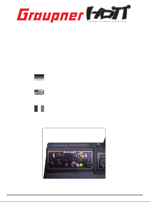
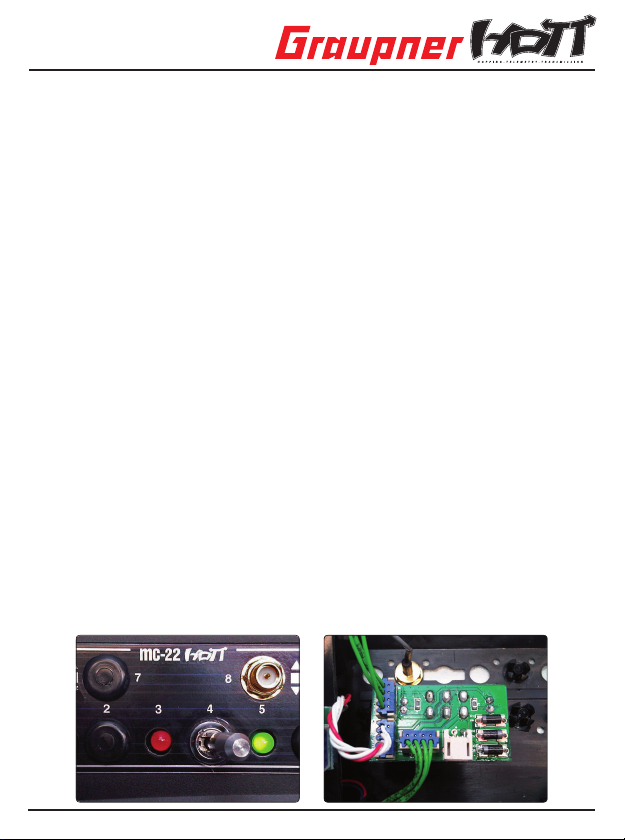
Öffnen Sie zuerst Ihren Sender und suchen nach einer geeigneten Stelle für den Umschalter. Im folgenden
wird der Einbau anhand des Pultsenders mc-22 HoTT beschrieben. Sehr gut geeignet sind die Optionsplätze oberhalb der Steuerknüppel. Entfernen Sie die Blindstopfen aus drei Optionsplätzen und befestigen den
HF-Umschalter mit der Ziermutter des Umschalters am Sender wie in der Abb. gezeigt.
01 Bedienungsanleitung HF-Umschalter 33303
Page 3
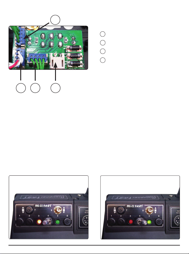
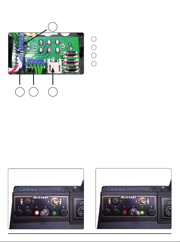
Der Umschalter hat auf der Rückseite vier Anschlussbuchsen.
2
1 HF-Stecker der Senderplatine (INPUT)
2 HF-Stecker Modul 1 (35 MHz - 2.4 GHz)
3 HF-Stecker Modul 2 (2.4 GHz)
4 HF-Stecker Weatronic Modul
3
1
Trennen Sie zuerst den von der Senderplatine kommenden HF-Stecker vom serienmäßigen Sendermodul
Ihrer Anlage. Dieser Stecker wird anschließend in Buchse 1 (INPUT) des Umschalters gesteckt.
Schließen Sie die Module mit den beiliegenden Verbindungskabeln wie in der Abb. gezeigt an. Die Stecker
sind verpolungssicher, achten Sie auf die seitlichen Nasen. Wenden Sie auf keinen Fall Gewalt an, der
Stecker sollte leicht einrasten.
35 MHz Module müssen an Buchse 2 angeschlossen werden, Buchse 3 ist für 2.4 GHz Module vorgesehen
(bzw. Buchse 4 für Weatronic-Module). Werden zwei 2.4 GHz Module verwendet, muss eines davon an
Buchse 2 angeschlossen werden.
BEACHTE:
die Buchsen 3 und 4 sind durchkontaktiert, bei Verwendung eines Weatronic Moduls muss deshalb Buchse
3 leer bleiben. Das zweite 2.4 GHz Modul wird dann an Buchse 2 angeschlossen. Ausserdem sollte das
Kabel des Weatronic Moduls im Gehäuse gesichert werden (z.B. durch einen Kabelbinder), damit sich der
Stecker nicht unbeabsichtigt lösen kann.
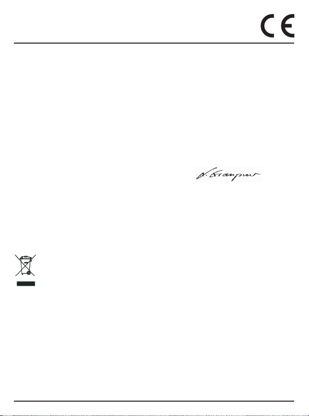
Der HF-Umschalter ist mit einem Sicherheitsumschalter versehen, d.h. Sie müssen am Hebel ziehen, um
ihn umlegen zu können. Ist Modul 1 aktiv (Anschluss 2), leuchtet die rote LED, bei aktivem Modul 2 (Anschluss 3 oder 4) die grüne LED.
Modul 1
aktiv
Bedienungsanleitung HF-Umschalter 33303 02
4
Modul 2
aktiv
Page 4
EG-KONFORMITÄTSERKLÄRUNG:
Für das nachfolgend bezeichnete Erzeugnis
HF-Umschalter 35MHz/IFS/Weatronic-HoTT Best.-Nr. 33303
wird hiermit bestätigt, dass es den wesentlichen Schutzanforderungen entspricht, die in der Richtlinie des
Rates zur Angleichung der Rechtsvorschriften der Mitgliedstaaten über die elektromagnetische Verträglichkeit 2004/108/EC
festgelegt sind.
Zur Beurteilung des Erzeugnisses wurden folgende Normen herangezogen:
EN 61000-6-1
EN 61000-6-3
Diese Erklärung wird verantwortlich für den Hersteller/Importeur
Graupner GmbH & Co. KG
Henriettenstr. 94-96
73230 Kirchheim/Teck
abgegeben durch den Geschäftsführer Stefan Graupner
73230 Kirchheim/Teck, den 30.03.2011 Unterschrift
Hinweise zum Umweltschutz
Das Symbol auf dem Produkt, der Gebrauchsanleitung oder der Verpackung weist darauf hin,
dass dieses Produkt am Ende seiner Lebensdauer nicht über den normalen Haushaltsabfall entsorgt werden darf. Es muss an einem Sammelpunkt für das Recycling von elektrischen und elektronischen Geräten abgegeben werden.
Die Werkstoffe sind gemäß ihrer Kennzeichnung wieder verwertbar. Mit der Wiederverwendung,
der stoffl ichen Verwertung oder anderen Formen der Verwertung von Altgeräten leisten Sie einen wichtigen
Beitrag zum Umweltschutz.
Batterien und Akkus müssen aus dem Gerät entfernt werden und bei einer entsprechenden Sammelstelle
getrennt entsorgt werden.
Bei RC-Modellen müssen Elektronikteile, wie z.B. Servos, Empfänger oder Fahrtenregler aus dem Produkt
ausgebaut und getrennt bei einer entsprechenden Sammelstelle als Elektro-Schrott entsorgt werden.
Bitte erkundigen Sie sich bei der Gemeindeverwaltung die zuständige Entsorgungsstelle.
03 Bedienungsanleitung HF-Umschalter 33303
Page 5

Manual RF-Selector Switch
Order No. 33303
These operating instructions are part of this product. They contains important notes to the operation and
handling. Please take this into consideration when you pass on the product to third parties. Neglect of the
operating instructions and the safety instructions lead to expiring the warranty.
Graupner constantly work on the advancement of all remote control systems; changes of the scope of delivery in form, technology and equipment we must reserve ourselves therefore.
Please have understanding for the fact that from data and illustrations of this operating instructions no
requirements can be derived.
Please keep these instructions for further reference!
SECURITY NOTE:
USE THE RF SWITCH ONLY WHEN THE TRANSMITTER IS TURNED OFF! OTHERWISE THE ELECTRONICS OF THE TRANSMITTER WILL BE DAMAGED.
1. INTRODUCTION
With the RF switch, you can choose between two transmitter modules, such as 35MHz, Graupner HoTT 2.4,
or Weatronic Graupner|IFS. So you can also integrate another RF module in the transmitter and if necessary, just switch between the modules.
Both the operating voltage and the PPM signal is switched with the safety switch so that only one module is
activated and consumes electricity. The active module is indicated by a green or red LED.
The following combinations are possible:
HoTT - Weatronic
HoTT - iFS
HoTT - 35 MHz
iFS - Weatronic
iFS - 35 MHz
Weatronic - 35 MHz
2. INSTALLATION
To use the RF switch a second RF module for your transmitter must be mounted. Make sure to use only
appropriate modules! Refer to the manual of the RF modules for proper installation.
First, open your transmitter and look for a suitable location for the switch. In the following, the installation
is described using the mc-22 HoTT transmitter. Very useful are the option wells above the control stick.
Remove the plugs from three option wells and fi x the RF switch with the ornamental mother of the switch on
the transmitter as shown in Fig.
Manual RF-Selector Switch 33303 04
Page 6

The switch has four connection sockets on the backside.
2
1 RF-plug of the transmitter circuit board
(INPUT)
2 RF-plug Module 1 (35 MHz - 2.4 GHz)
3 RF-plug Module 2 (2.4 GHz)
4 RF-plug Weatronic Module
3
1
First, unplug the RF connector coming from the transmitter circuit board from the standard transmitter module of your radio system. This connector is then plugged into connection socket 1 (INPUT) of the switch.
Connect the modules with the included cables as shown in the fi gure above. The sockets are also polarised;
note the small noses on the side. Never use force - the plugs should engage easily and fully. 35 MHz modules must be connected to socket 2, socket 3 is provided for 2.4 GHz modules (or socket 4 for Weatronic
modules). If two 2.4 GHz modules are used, one must be connected to socket 2.
NOTE:
the sockets 3 and 4 are contacted, when using a Weatronic module socket 3 must remain empty. The
second 2.4 GHz module is then connected to socket 2. In addition, the Weatronic cable should be secured in
the transmitter case (eg. by a cable tie), so that the plug can not be released accidentally.
The RF switch has a safety switch, ie you have to pull the lever to move the switch. The red LED lits when
module 1 (socket 2) is activated, the green LED lits when module 2 (socket 3 or 4) is active.
Module 1
activated
4
Module 2
activated
05 Manual RF-Selector Switch 33303
Page 7

EG DECLARATION OF CONFORMITY:
We hereby declare that the following product:
RF-Selector switch 35MHz/IFS/Weatronic-HoTT order.-no. 33303
confi rms with the essential protective requirements as laid down in the directive for harmonising the statua-
tory directives of the member states concerning electro-magnetic interference 2004/108/EC.
This product has been tested for electro-magnetic interference in accordance with the following norms:
EN 61000-6-1
EN 61000-6-3
This declaration was produced by
Graupner GmbH & Co. KG
Henriettenstr. 94-96
73230 Kirchheim/Teck
and is valid for the manufacturer / importer of the product
73230 Kirchheim/Teck, den 30.03.2011 Stefan Graupner
Managing Director
Environmental Protection Notes
When this product comes to the end of its useful life, you must not dispose of it in the ordinary domestic waste. The correct method of disposal is to take it to your local collection point for recycling
electrical and electronic equipment. The symbol shown here, which may be found on the product
itself, in the operating instructions or on the packaging, indicates that this is the case.
Individual markings indicate which materials can be recycled and re-used. You can make an
important contribution to the protection of our common environment by re-using the product, recycling the
basic materials or recycling redundant equipment in other ways.
Remove batteries from your device and dispose of them at your local collection point for batteries.
In case of R/C models, you have to remove electronic parts like servos, receiver or speed controller from the
product in question, and these parts must be disposed of with a corresponding collection point for electrical
scrap.
If you don’t know the location of your nearest disposal centre, please enquire at your local council offi ce.
Manual RF-Selector Switch 33303 06
Page 8

Mode d‘emploi HF-Commutateur
Réf N°. 33303
Cette notice d’utilisation fait partie intégrante du produit. Elle contient d’importantes consignes pour une
utilisation en toute sécurité du produit. Gardez-la précieuselment et transmettez-la, en cas de revente, au
nouvel acquéreur. Le non-respect de cette notice et des consignes de sécurité qui y fi gurent, conduisent à
une extinction du droit à la garantie.
Graupner travaille constamment à l’élaboration et à l’évolution de ses produits; c’est pourquoi nous sommes
contraints de nous réserver tous droits de modifi cations, que ce soit au niveau de la forme du produit, de sa
technologie ou de l’équipement des kits proposés.
Les indications et photos de cette notice ne peuvent faire l’objet d’aucune réclamation, nous vous remercions de votre compréhension.
C’est une des raisons pour lesquelles il faut toujours garder cette notice à portée de main, afi n de pouvoir
la consulter à tout moment!
CONSIGNE DE SECURITE:
N’UTILISEZ LE COMMUTATEUR HF QUE LORSQUE L’EMETTEUR EST COUPE! SINON, VOUS
ENDOMMAGEZ L’ELECTRONIQUE DE L’EMETTEUR.
1. INTRODUCTION
Avec ce commutateur HF, vous pouvez basculer entre deux modules émetteur, par exemple, 35MHz,
Graupner HoTT 2.4, Weatronic ou Graupner|iFs. Vous pouvez ainsi encore intégrer un autre module HF
supplémentaire dans votre émetteur, module que vous pourrez activer, en cas de besoin, simplement par
un interrupteur.
Avec l’interrupteur de sécurité, on ne bascule non seulement la tension d’utilisation, mais également le signal PPM, de manière à ce que seulement un seul module puisse émettre et consommer. Le module activé
est visualisé par une LED verte ou rouge.
Les combinaisons suivantes sont possibles:
HoTT - Weatronic
HoTT - iFS
HoTT - 35 MHz
iFS - Weatronic
iFS - 35 MHz
Weatronic - 35 MHz
2. MONTAGE
Pour pouvoir utiliser le commutateur HF, il faut qu’un deuxième module HF soit monté dans votre émetteur.
Assurez-vous de n’utiliser que des modules appropriés! Pour un montage correct, consultez également les
notices des modules.
Ouvrez d’abord votre émetteur et cherchez un endroit adéquat pour loger le commutateur. Dans
ce qui suit, nous décrivons le montage dans un émetteur sur pupitre mc-22 HoTT. Les emplacements
07 Mode d‘emploi HF-commutateur 33303
Page 9
au-dessus des manches de commande conviennent parfaitement. Retirez les bouchons obturateurs de trois
emplacements optionnels et fi xez le commutateur HF avec l’écrou moleté du commutateur sur l’émetteur,
selon la photo.
2
A l’arrière, le commutateur a quatre prises de branchement.
1 Prise HF de la platine émetteur (INPUT)
2 Prise HF Module 1 (35 MHz - 2.4 GHz)
3 Prise HF Module 2 (2.4 GHz)
4 Prise HF Module Weatronic
3
1
Débranchez d’abord la prise HF qui vient de la platine émetteur, du module d’émission d’origine. Cette prise
sera ensuite branchée dans la fi che 1 (INPUT) du commutateur.
Branchez les prises des cordons selon la photo. Les prises sont équipées de détrompeurs, attention aux petites pattes sur le coté de la prise. Ne forcez pas, la prise doit pouvoir se monter, s’enclencher facilement.
Les modules 35 MHz doivent être branchés dans la fi che 2, la fi che 3 est réservée aux modules en 2.4
GHz (la fi che 4 aux modules Weatronic). Si vous utilisez deux modules en 2.4 GHz, un des deux doit être
branché dans la fi che 2.
ATTENTION:
Les fi ches 3 et 4 sont passantes, si vous utilisez un module Weatronic, la fi che 3 doit restée libre. Le deu-
xième module en 2.4 GHz sera ensuite branché sur la fi che 2. Par ailleurs, le cordon du module Weatronic
doit être fi xé dans le boîtier, (par ex. avec un collier rilsan) pour que la prise ne puisse pas se débrancher
involontairement.
Le commutateur HF est équipé d’un interrupteur de sécurité, c’est-à-dire, il faut tirer sur le levier pour pouvoir
le basculer. Si le module 1 (fi che 2) est activé, c’est la LED rouge qui est allumée, si c’est le module 2 (fi che
3 ou 4), c’est la LED verte.
Module 1
activé
Mode d‘emploi HF-commutateur 33303 08
4
Module 2
activé
Page 10

DÉCLARATION DE CONFORMITÉ EG:
Pour le produit suivant:
HF-Commutateur 35MHz/IFS/Weatronic-HoTT Réf. N°: 33303
Nous confi rmons que la compatibilité électronique correspond aux directives 2004/108/EC.
Normes appliquées:
EN 61000-6-1
EN 61000-6-3
Cette déclaration est sous la responsabilité du Fabricant / Importeur
Graupner GmbH & Co. KG
Henriettenstr. 94-96
73230 Kirchheim/Teck
Fait à
73230 Kirchheim/Teck, den 30.03.2011
Stefan Graupner
Le director d‘Entreprise
Indications quand à la protection de l‘environnement
Ce produit à la fi n de sa durée de vie ne doit pas être mis à la poubelle, mais être remis à une
collecte pour le recycle ment d‘appareils électriques et électroniques. Le symbole inscrit sur le
produit, dans la notice d‘instructions et sur son emballage l‘indique.
Les matériaux selon leurs reconnaissances sont réutilisables. Avec le recyclage de matériaux et
autres formes d‘appareils, vous contribuez à la protection de l‘environnement.
Les batteries et accus doivent être retirés de l‘appareil et doivent être remis à un dépôt homologué pour ce
type de produits.
Pour les modèles radiocommandes, les pièces électroniques, comme par exemple les servos, récepteur
ou variateur de vitesse, doivent être démontés et retirés du produit et être remis à une collecte spécialisée
pour produits électroniques.
Veuillez s.v.p. demander auprès de votre mairie l‘adresse exacte de la collecte la plus proche de chez
vous.
09 Mode d‘emploi HF-commutateur 33303
Page 11

Wir gewähren auf dieses Erzeugnis eine /
Garantie von
warrantied for
garantie de
Die Fa. Graupner GmbH & Co. KG, Henriettenstraße 94-96,
73230 Kirchheim/Teck gewährt ab dem Kaufdatum auf
dieses Produkt eine Garantie von 24 Monaten. Die Garantie gilt nur für die bereits beim Kauf des Produktes vorhandenen Material- oder Funktionsmängel. Schäden, die auf
Abnützung, Überlastung, falsches Zubehör oder unsachgemäße Behandlung zurückzuführen sind, sind von der
Garantie ausgeschlossen. Die gesetzlichen Rechte und
Gewährleistunsansprüche des Verbrauchers werden durch
diese Garantie nicht berührt. Bitte überprüfen Sie vor einer Reklamation oder Rücksendung das Produkt genau
auf Mängel, da wir Ihnen bei Mängelfreiheit die entstandenen Unkosten in Rechnung stellen müssen.
Graupner GmbH & Co. KG, Henriettenstraße 94-96, 73230
Kirchheim/Teck, Germany guarantees this product for a period of 24 months from date of purchase. The guarantee
applies only to such material or operational defects witch
are present at the time of purchase of the product. Damage due to wear, overloading, incompetent handling or the
use of incorrect accessories is not covered by the guarantee. The user´s legal rights and claims under garantee are
not affected by this guarantee. Please check the product
carefully for defects before you are make a claim or send
the item to us, since we are obliged to make a charge for
our cost if the product is found to be free of faults.
La société Graupner GmbH & Co. KG, Henriettenstraße
94-96, 73230 Kirchheim/Teck, Allemagne, accorde sur ce
produit une garantie de 24 mois à partir de la date d´achat.
La garantie prend effet uniquement sur les vices de fonction-nement et de matériel du produit acheté. Les dommages dûs à de l´usure, à de la surcharge, à de mauvais
accessoires ou à d´une application inadaptée, sont exclus de la garantie. Cette garantie ne remet pas en cause les droits et prétentions légaux du consommateur.
Avant toute réclamation et tout retour du prouit, veuillez
s.v.p. cotrôler et noter exactement les défauts ou vices.
Garantie-Urkunde
Warranty certifi cate / Certifi cate de garantie
HF-Umschalter 35MHz/IFS/Weatronic-HoTT
RF-Selector switch 35MHz/IFS/Weatronic-HoTT
HF-Commutateur 35MHz/IFS/Weatronic-HoTT
Übergabedatum
Date of purchase/delivery
Date de remise
33303
This product is /
24
Sur ce produit nous accordons une
Monaten
months
mois
Servicestellen / Service / Service après-vente
Graupner-Zentralservice
Graupner GmbH & Co. KG
Henriettenstrasse 94-96
D-73230 Kirchheim / Teck
Belgie/Nederland
Jan van Mouwerik
Slot de Houvelaan 30
NL 3155 Maasland VT
(+31)10 59 13 59 4
Republika
RC Service Z. Hnizdil
Letecka 666/22
CZ-16100 Praha 6 - Ruzyne
(+42) 2 33 31 30 95
Anguera Hobbies
C/Terrassa 14
E 43206 Reus (Tarragona)
(+34) 97 77 55 32 0
France UK
Graupner Service France
Gérard Altmayer
86, rue St. Antoine
F 57601 Forbach-Oeting
(+33) 3 87 85 62 12
Italia
GiMax
Via Manzoni, no. 8
I 25064 Gussago
(+39) 30 25 22 73 2
Servicehotline
(+49) 01805 47 28 76
Montag - Freitag 7:30 -11:45
und 12:30 -16:00 Uhr
Luxembourg
Kit Flammang
129, route d’Arlon
L 8009 Strassen
(+35) 23 12 23 2
SchweizCeská Republika/Slovenská
Graupner Service Schweiz
CD-Electronics GmbH
Kirchweg 18
CH-5614 Sarmenstorf
(+41) 56 66 71 49 1
SverigeEspana
Baltechno Electronics
P.O. Box 5307
S 40227 Göteborg
(+46) 31 70 73 00 0
Graupner Service UK
Brunel Drive
GB, NEWARK, Nottinghamshire
NG242EG
(+44) 16 36 61 05 39
Name des Käufers
Owner´s name
Nom de I`achateur
Straße, Wohnort
Complete adress
Domicie et rue
Firmenstempel und Unterschrift
des Einzelhändlers
Stamp and signature of dealer
Cachet de la fi rme et signature
du detailant
10
Page 12

Graupner GmbH & Co. KG
Henriettenstraße 94 – 96
D-73230 Kirchheim/Teck
Germany
www.graupner.de
Änderungen sowie Liefermöglichkeiten vorbehalten. Lieferung durch den Fachhandel. Bezugsquellen werden nachgewiesen. Für Druckfehler kann keine Haftung übernommen werden.
Specifi cations and availability subject to change. Supplied through specialist model shops only. We will
gladly inform you of your nearest supplier. We accept no liability for printing errors.
Sous réserve de modifi cations et de possibilité de livraison. Livraison uniquement au travers de magasins
spécialisés en modélisme. Nous pourrons vous communiquer l’adresse de votre revendeur le plus proche.
Nous ne sommes pas responsables d’éventuelles erreurs d’impression.
Con riserva di variazione delle specifi che e disponibilità del prodotto. Fornitura attraverso rivenditori specia-
lizzati.Saremmo lieti di potervi indicare il punto vendita più vicino a voi. Si declina qualsiasi responsabilità
per errori di stampa.
März 2011 - DE-EN-FR V1.0
 Loading...