

Page 1
Manual
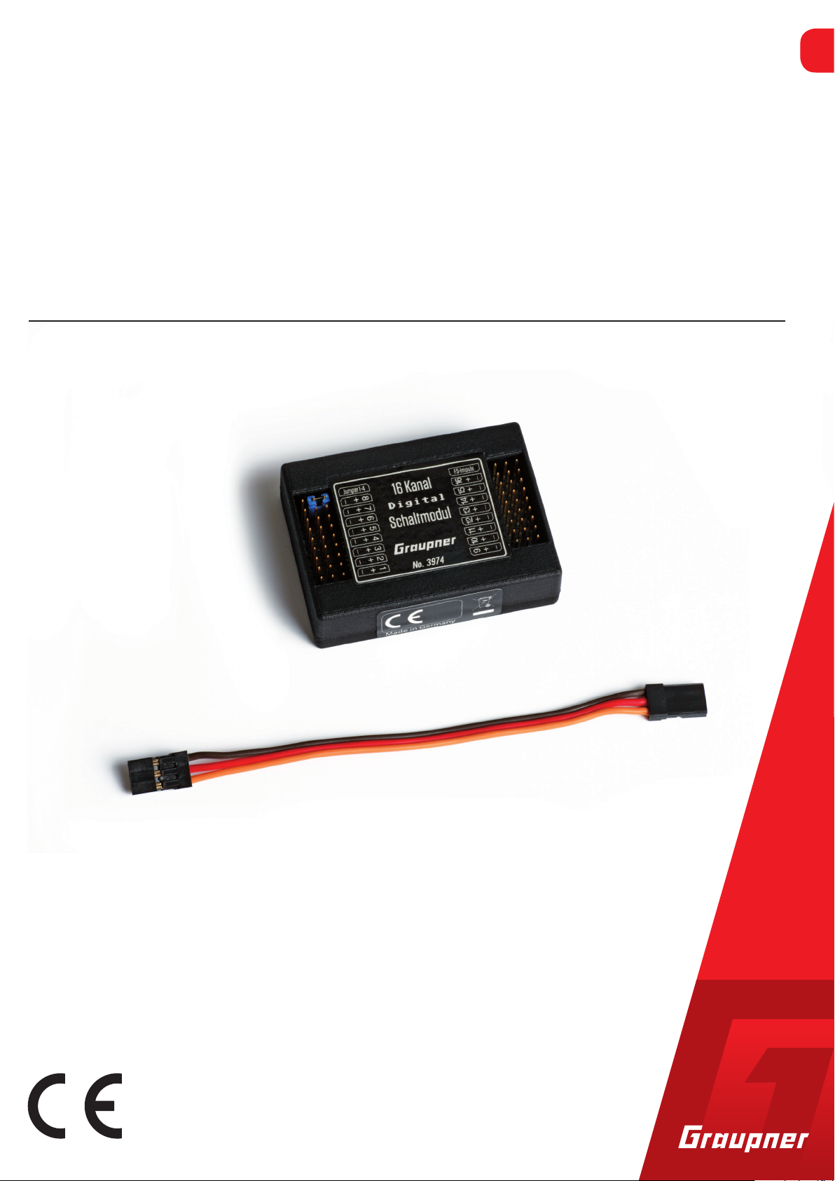
16 channel digital switch module
SumD V3 capable matching mz-16 / mz-32 / mc-16 Expert / mc-32 Expert
No. 3974
EN
Copyright © Graupner/SJ GmbH
Page 2

Page 3

Index
Personal notes ......................................................................................... 4
Introduction ............................................................................................ 5
Service centre .......................................................................................... 5
Intended use ........................................................................................... 6
Package content ...................................................................................... 6
Declaration of conformity ..................................................................... 6
Technical data ......................................................................................... 7
Description .............................................................................................. 7
Symbol description ................................................................................. 8
Safety notes .............................................................................................. 8
Installing the module ............................................................................. 9
Setting the electric connections .......................................................... 10
Connection diagram ............................................................................ 12
Note on use of switch relais ................................................................. 12
Programming of receiver and digital switches ................................. 13
Naming the Digital Switches ............................................................... 14
Mode of a digital switch ....................................................................... 14
Arranging the digital switches ............................................................ 15
Using multiple switch modules ......................................................... 16
Firmware update .................................................................................. 18
Notes on environmental protection ................................................... 19
Care and maintenance ......................................................................... 19
Warranty conditions ............................................................................ 19
3974_MP_V3
3 / 19
Page 4

Personal notes
Page 5
Introduction
Thank you very much for purchasing a Graupner 16 channel digital
switch module.
Read this manual carefully to achieve the best results with module
and first of all to safely control your models. If you experience any
trouble during operation, take the instructions to help or ask your
dealer or Graupner Service Centre.
Due to technical changes, the information may be changed in this
manual without prior notice. Be always updated by checking periodically on our website, www.graupner.de to be always updated with
the products and firmware.
This product complies with national and European legal requirements.
To maintain this condition and to ensure safe operation, you must
read and follow this user manual and the safety notes before using
the product!
NOTE
This manual is part of that product. It contains important information concerning operation and handling. Keep these instructions for
future reference and give it to third person in case you gave the product.
Service centre
Graupner Central Service
Graupner GmbH
Henriettenstraße 96
D-73230 Kirchheim / Teck
Graupner USA
3941 Park Dr Suite 20-571
El Dorado Hills, CA 95762
Graupner in Internet For the service centers outside Germany please refer to our web site
www.graupner.de
Servicehotline
(+49) (0)7021/722-130
Monday - Thursday:
9:15 am -4:00 pm
Friday:
9:15 am - 1:00 pm
service@graupner.de
Website: www.graupnerusa.com
Phone: +1 855-572-4746
Email:service@graupnerusa.com
3974_MP_V3
5 / 19
Page 6
Intended use
Package content
The module has to be controlled through a digital switch of your
transmitter and it is designed exclusively to be used in battery-powered, radio controlled models, any other use is not allowed. For any
improper use no guarantee or liability is assumed.
Read through this entire manual before you attempt to install or use
the module.
Graupner/SJ constantly works on the development of all products;
we reserve the right to change the item, its technology and equipment.
Target group
The item is not a toy. It is not suitable for children under 14. The
installation and operation must be performed by experienced modellers. If you do not have sufficient knowledge about dealing with
radio-controlled models, please contact an experienced modeller or
a model club.
Declaration of conformity
Switch module
1 patch cable 10 cm
Operating instructions
2 jumpers
No. 3974 16 channel digital switch module
Graupner/SJ hereby declares that the
16 channel digital switch module (No.3974) is conform to EU norms.
DIN EN 55014-1
6 / 19
3974_MP_V3
Page 7
Technical data
Description
16 channel digital switch module
Operating voltage 4,0 - 13,0 V
Operating current < 10mA at 6,0 V
Max. switch current pro chan-
nel
Max. switch voltage 18.0 V
Inpulse input voltage < 6,0 V
Weight approx. 16 g
Dimensions 57 x 42 x 15 mm
Operating temperature 0 - 40 °C
Required control channels 1 through SumD3
NOTE
The technical data of the optional receiver are available in the manual included in the receiver package content.
The Graupner transmitters mz-16, mz-32, mc-16 Expert and mc-32
Expert offer the possibility of controlling up to 16 different components on the receiver side via the sum signal. The module works
exclusively via the digital switches of the above mentioned transmitters.
3.0 A
The signals of the digital switches on the transmitter touch screen are
transmitted digitally, therefore the components are switched on and
off without delay and interference-free.
Through the suitable cabling of the connection cable the functions
can be powered by a single power source or separately by different
power sources.
(with a common ground, so not electrically isolated)
The compatible GR-12 / GR-16 / GR-24 / GR-32 receivers must be
up-to-date for SumD V3 software.
Go to:
www.graupner.de/UBlog/Empfaenger
3974_MP_V3
7 / 19
Page 8
Symbol description
!
!
Safety notes
Always observe the information indicated by this warning sign. Par-
ticularly those which are additionally marked with the words CAU
TION or WARNING. The signal word WARNING indicates the
potential for serious injury, the signal word CAUTION indicates
possibility of lighter injuries.
The signal word Note indicates potential malfunctions.
Attention indicates potential damages to objects.
General
These safety instructions are intended not only to protect your own
and other people’s safety, but also to protect the product. Therefore
please read this section very carefully before using the product!
Do not leave the packaging material lying around, this could be
a dangerous toy for children.
Persons, including children, with reduced physical, sensory or
mental capabilities, or lack of experience or knowledge, or not
capable to use safely the transmitter must not use the transmitter
without supervision or instruction by a responsible person.
Operation and use of radio-controlled models needs to be
learned! If you have never driven such a model, then start extra
carefully and make sure to be familiar with the reactions of the
model to the remote control commands. Proceed always responsibly. This also means that you have for your own protection liability insurance.
Protect all equipment from dust, dirt, moisture. All equipment
must be protected from vibration as well as excessive heat or cold.
The models may only be operated remotely in normal outside
temperatures such as from -10°C to +55°C.
8 / 19
Page 9

Installing the module
The 16 channel digital switch module has been developed for use in
RC models and it should only be used for the previewed scope.
Please note that the module should only be used within the indicated
limit values (see technical data).
Use and store the unit in a dry environment only.
Every mechanical or electric modification of the module or the trespassing of the indicated limit values brings immediately to loss of all
dispute rights against the producer, including the warranty service.
Any damage on the warranty seal on the back part of the module also
brings to an immediate loss of waranty.
Always proof the correct functions of the module before every use.
The best solution is to fix the module through some double-sided
adhesive tape or hook and loop tape in the model.
Never open the housing and always plug in and out the switched off
components. This will prevent damage to the module and the receiver.
3974_MP_V3
9 / 19
Page 10

Setting the electric connections
The module consumes so little power that you can connect it directly
to the summed signal output (see receiver instructions) with the
included patch cable.
You can connect functions with low power consumption directly to
the switch channel of the module, but only if the total power consumption of all the connected functions is lower than 1,0 A and only
if the receiver voltage is enough (see switch plan).
To allow an as universal as possible use of the module, the module
switches the ground (GND). This has the positive aspect that if necessary each function can be powered by a different source.
To allow this it is important that the minus pole of each power source,
e.g. batteries, is connected to the other ones.
The functions will then be connected securely with the plus pole to
the related battery and the minus pole of the function will be connected to the switch module.
In case of low currents the ground connection through the patch
cable of the receiver is enough, on the other hand if the current is
higher you should connect each ground separately (see switch plan).
Please note that inductive or capacitive functions ( as relais, motors
or capacitors, etc...) during the switch-on phase can require much
higher current than the one needed during the normal use. A trespassing of the limit values can damage the module.
10 / 19
3974_MP_V3
Page 11

Connection of a small component eg. to channel 9
Sum signal through channel 6
Receiver
GR-12
X1 A B C X2 C B A
0
X2 - 9B
Component
Connection of a big component to channel 9
Sum signal through channel 6
Receiver
GR-12
X1 A B C X2 C B A
X2 - 9C
+4...18 V
0
max. 3.0 A
X2 - 9A
Accessory ground
X2 - 9C
In case of currents higher than 1,0 A connect, as represented, an accessory ground (GND) line to the related
pin A of the channel (as shown in the illustration). Overloading of the tracks on the module is thus prevented.
3974_MP_V3
11 / 19
Page 12

Connection diagram
!
Jumper
depending on the number of switching modules (See page 17)
Transmitter pulse (sum signal)
Outputs: For GR-12 ch. 6 (from Software 7a..)
For GR-16 ch. 8 (from Software 7a..)
For GR-24 ch. 8 (from Software 7a..)
For GR-32 channel S (from Software 7a..)
1
X1 A B C
16 Kanal
Schaltmodul
No. 3974
Switch relais
Polarity inver-
sion module
0
X2 C B A
1
4
4
4
No. 4159.1
No. 4159.2
2
3
1
2
3
1
2
3
Note on use of switch relais
In case of use of the Graupner switch relais please pay attention
to the inverted polarity!
See connection scheme on the left.
In case of use of a No.4159.3 it is necessary to create a
connection cable because the polarity inversion is split to
two connectors.
e.g. No. S8189 and 33700.2 combined. Remove remaining
strands according to the scheme.
1
2
5
No. 4159.3
3
4
Occupation of the pin lines:
X1 X2
Pin A B C Pin C B A
9 Jumper Jumper Jumper 18 FS pulse V+ GND
8 GND V+ Ch 8 17 Ch 16 V+ GND
7 GND V+ Ch 7 16 Ch 15 V+ GND
6 GND V+ Ch 6 15 Ch 14 V+ GND
5 GND V+ Ch 5 14 Ch 13 V+ GND
4 GND V+ Ch 4 13 Ch 12 V+ GND
3 GND V+ Ch 3 12 Ch 11 V+ GND
2 GND V+ Ch 2 11 Ch 10 V+ GND
1 GND V+ Ch 1 10 Ch 9 V+ GND
12 / 19
3974_MP_V3
Page 13
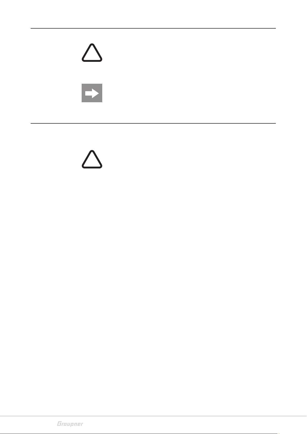
Programming of receiver and digital switches
For the transmitter to be able to transmit the data correctly, settings
must be made on the transmitter and receiver:
Enter the "Telemetry" menu of the transmitter, open the "Settings &
view" line and move through the touch pads to the "CH OUT TYPE"
line. Here please select the "SUMD3" mode.
This transmission mode is absolutely necessary for the use of the
module! To do this, the receiver must have the latest software version. (from V7a..)
Switch active
Switch inactive
To assign the digital switches, call up the menu in the transmitter:
Depending on the transmitter, 16-64 digital switches are available
here.
mz-16: 16 digital switches
mz-32 : 64 difital switches
mc-16 Expert: 16 digital switches
mc-32 Expert: 64 digital switches
3974_MP_V3
1. The switch is activated via menu item "Act". By tapping the plug
symbol is closed. Now it is active.
(As an example, the screenshot above renamed the first two switches.
This name will appear later on the display with the switch symbol.)
13 / 19
Page 14
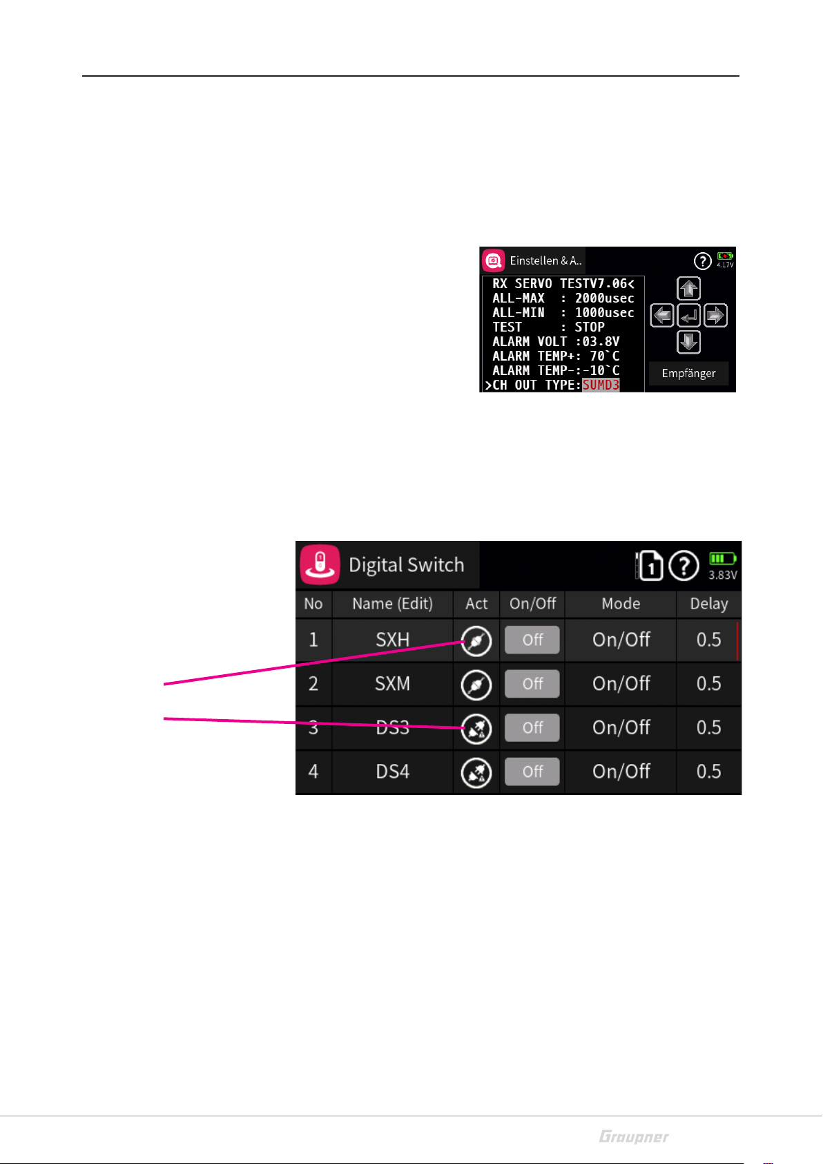
Naming the Digital Switches
1
2
1. First, tap the switch number.
2. Touch the edit pen
3. Input the name
4. Push Return
3
Mode of a digital switch
4
There are 3 modes available:
1. ON/OFF
14 / 19
2. Pulse
3. Flash
3974_MP_V3
Page 15
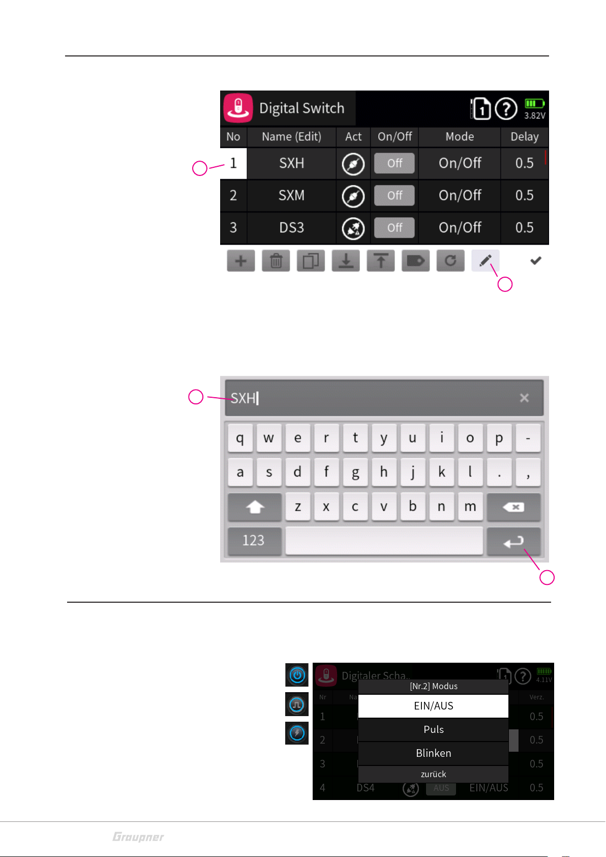
Arranging the digital switches
After naming the switches and selecting the mode, the switches can
now be linked on the start screen of the transmitter.
If you press the switch, it lights up permanently, flashes briefly or flashes
permanently.
3974_MP_V3
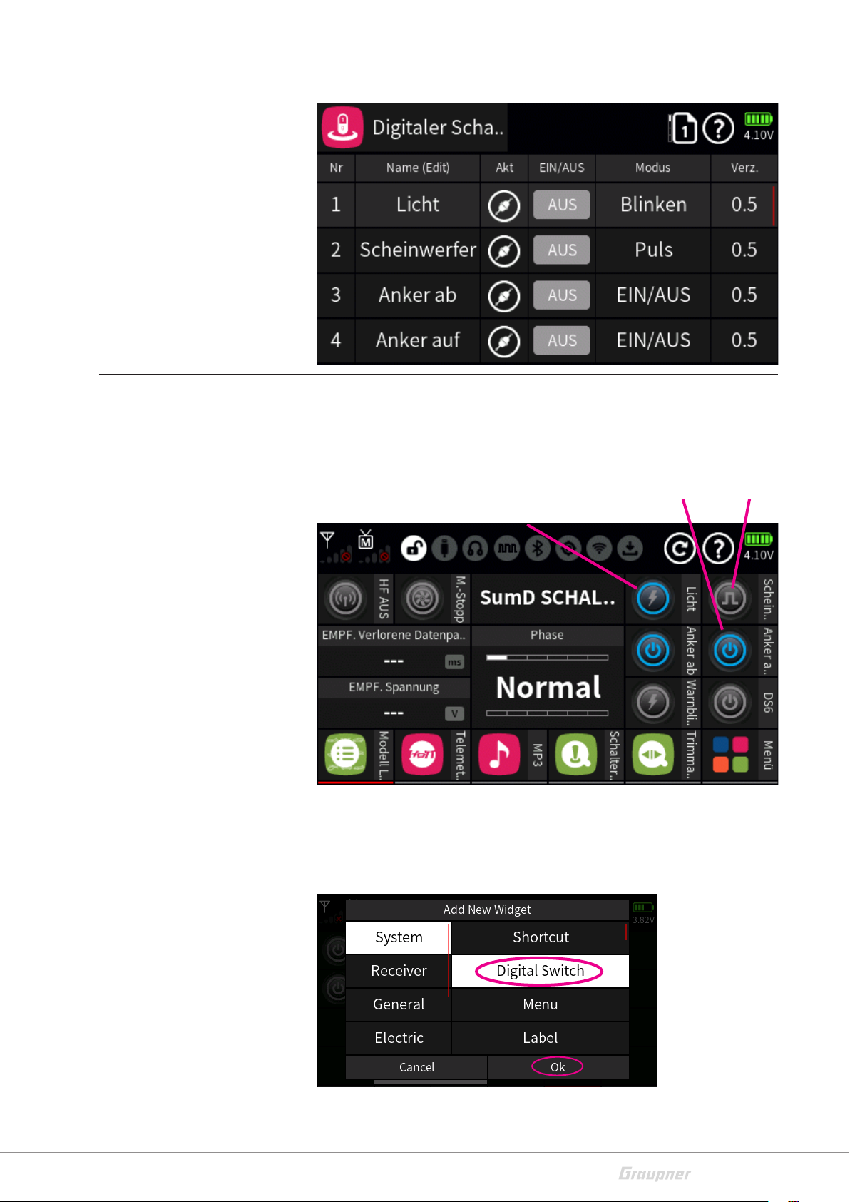
Procedure:
Touch an empty field on the touch screen for more than 2 seconds.
Select "Digital switch" and press OK.
15 / 19
Page 16

There are four
switch groups
Then a second window will appear, in which the group and then the
switch itself will be selected:
Select the appropriate switch and press OK.
After confirming with OK the respective switch appears directly on the touch screen.
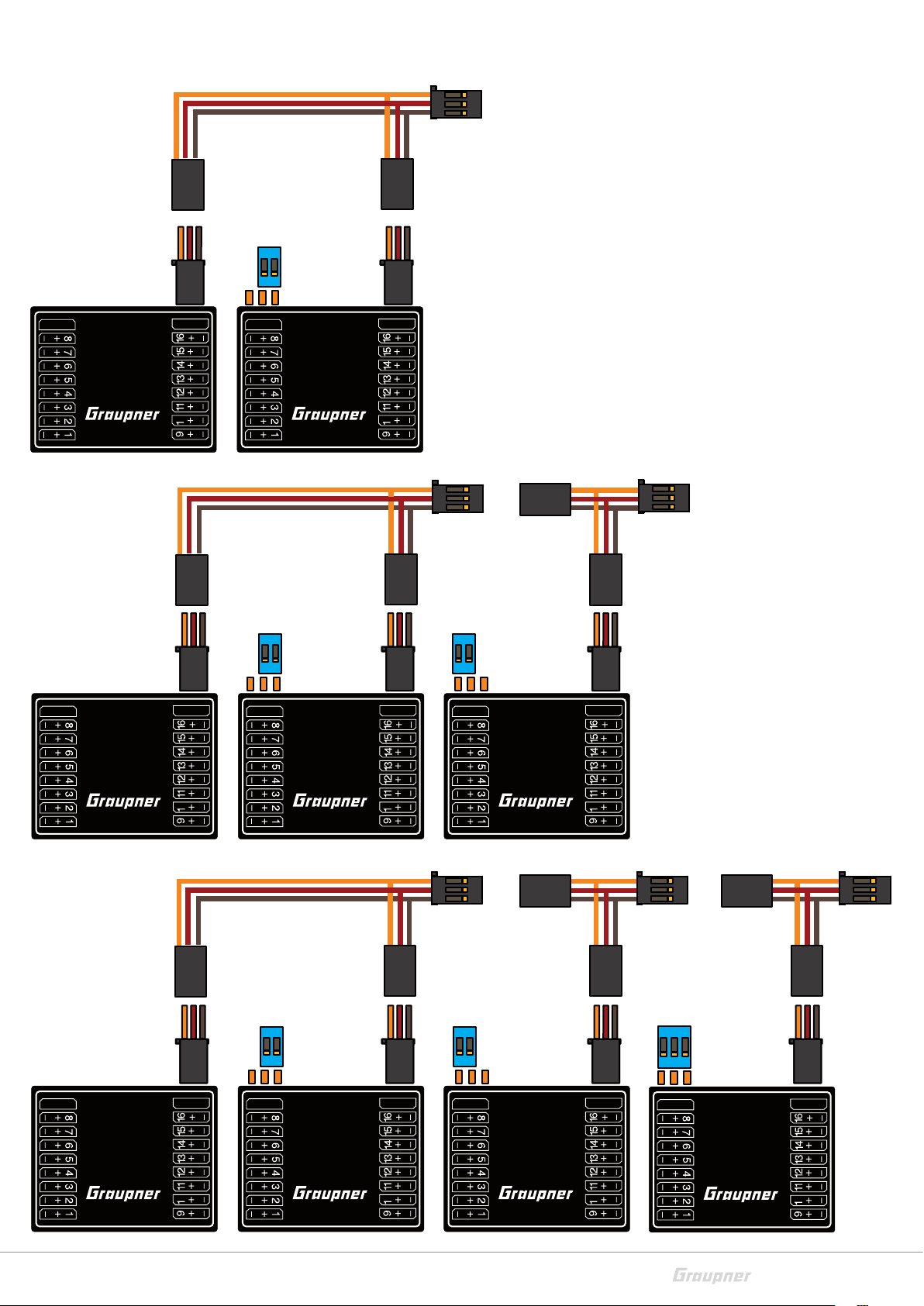
Using multiple switch modules
To operate all 64 digital switches, it is possible to connect up to 4
modules. Here the jumpers are used.
Using 1 Module: No Jumper 1. Module Channels 1-16
Using 2 Modules: + 2 poles Jumper right 2. Module Channels 17-32
Using 3 Modules: + 2 poles Jumper left 3. Module Channels 33-48
Using 4 Modules: + 3 poles Jumper 4. Module Channels 49-64
Also only 1 module can be used and this e.g. switches channels 17-32. Important here is only the plug
position of the jumpers.
Modules can also be connected in parallel, ie one in the cab, the other in the trailer or semi-trailer.
Both modules, for example, without jumpers for channels 1-16. So these are switched simultaneously.
As an example, the turn signals, hazard lights, headlights on the tractor and the semi-trailer.
16 / 19
3974_MP_V3
Page 17
Connection diagram several modules
Patch cable
+Y cable
(No.S8186)
9B + 9C
0
0
No. 3974 No. 3974
Patch cable
+Y cable
(No.S8186)
9B + 9C
0
0
Patch cable
+Y cable
(No.S8186)
9A + 9B
No. 3974 No. 3974 No. 3974
0
Patch cable
+Y cable
(No.S8186)
9B + 9C
0
0
Patch cable
+Y cable
(No.S8186)
9A + 9B
0
Patch cable
+Y cable
(No.S8186)
9A + 9B + 9c
No. 3974 No. 3974 No. 3974 No. 3974
3974_MP_V3
0
17 / 19
Page 18

Firmware update
The 16-channel digital switching module has been specially developed for the Graupner HOTT 2.4 GHz transmission system and
requires no further adaptation. If you have any question or problem
during the use, please contact us under Hotline service@graupner.
de or +49 (7021) 722-130.
18 / 19
3974_MP_V3
Page 19

Notes on environmental protection
P
Disposal notes
If this symbol is on the product, instructions for use or packaging, it
indicates that the product may not be disposed with normal household waste once it has reached the end of its service life. It must be
turned over to a recycling collection point for electric and electronic
apparatus.
Individual markings indicate which materials can be recycled. You
make an important contribution to protection of the environment by
utilizing facilities for reuse, material recycling or other means of
exploiting obsolete equipment.
Batteries must be removed from the unit and disposed of separately
at an appropriate collection point. Please inquire with local authorities about the responsible waste collection locations.
Care and maintenance
Notes on care
The product does not need any maintenance, it works so as it is with-
out any special care. In your own interest please protect the model
from dust, dirty and humidity!
Warranty conditions
Graupner, Henriettenstrassee 96, 73230 Kirchheim/Teck grants from
the date of purchase of this product for a period of 24 months. The
warranty applies only to the material or operational defects already
existing when you purchased the item. Damage due to misuse, wear,
overloading, incorrect accessories or improper handling are excluded
from the guarantee. The legal rights and claims are not affected by
this guarantee. Please check exactly defects before a claim or send the
product, because we have to ask you to pay shipping costs if the item
is free from defects.
The present construction or user manual is for informational purposes only and may be changed without prior notice. The current
version can be found on the Internet at www.graupner.de on the relevant product page. In addition, the company Graupner has no
responsibility or liability for any errors or inaccuracies that may
appear in construction or operation manuals.
Not liable for printing errors.
3974_MP_V3
19 / 19
 Loading...