

Page 1
mc-16 / mc- 2 0 HoTT.1.en
mc-16
mc-20
Programming Manual
Page 2

Table of contents
General notices
Table of contents .......................................................2
Environmental protection notices ..............................3
Safety notices ............................................................4
Safety notices and handling regulations for
Lithium-Ion (LiIo) and Lithium-Polymer (LiPo)
batteries .....................................................................8
Foreword ..................................................................10
Remote control set description ................................11
Technical data .......................................................... 15
General operating notices
Transmitter ..........................................................16
Transmitter power supply...............................16
Charging the transmitter battery ....................16
Charging with automatic chargers .................16
Recommended chargers (accessory) ...........16
Removing the transmitter’s battery ................17
Inserting the transmitter’s battery ..................17
Battery operation timer .................................17
General charging notices ..............................17
Opening the transmitter housing ...................18
Lithium battery CR 2032 ...............................18
Stick conversions ...........................................19
Stick length adjustment .................................20
Transmitter neckstrap support bars ............... 20
Transmitter description
Front side.......................................................21
Face-side connectors
Charger socket .........................................22
DSC jack ..................................................22
Data jack ..................................................23
Headset connector ...................................23
Card slot ...................................................24
Mini-USB connector .................................25
Bottom side transmitter interior .....................26
Display and keypad .......................................28
Operating the “data terminal“ ........................29
Shortcuts ....................................................... 30
Concealed menu columns .............................31
Table of contents
2
Function fields in the display .........................32
Position indicator ...........................................32
Entry lockout ..................................................32
Warning notices .............................................33
HIDDEN MODE .............................................34
Language selection
VOICE .................................................34
Change of display language ................35
Firmware update via SD card ...................35
STICK CALIBRATION .............................. 36
Bluetooth initialisation ..............................37
Telemetry data display ................................... 38
Commissioning the transmitter ................................46
Downloading a firmware packet .........................48
Transmitter firmware updates .............................50
Restoring the transmitter software .....................52
Receiver initialization ...............................................54
Receiver power supply .......................................56
Receiver system power supply ...........................57
Receiver firmware updates .................................58
Backing up receiver settings ...............................62
Installation notices ...................................................64
Definitions of terms ..................................................66
Physical control, switch and control switch assign-
ments .......................................................................68
Digital trim ...............................................................70
Winged models ........................................................72
Receiver layout ...................................................73
Servos in wrong direction ...................................73
Helicopter models ....................................................74
Receiver layout ...................................................75
Program descriptions
mc
16 20*
Loading a new memory location ..............................76
»Model select« .................................... 79
»Copy / Erase« .................................... 80
»Suppress codes« .............................. 84
»Suppress models« ............................ 85
»Base setup model«
Winged model ....................................................86
“Binding” transmitter and receiver .................87
Range test .....................................................91
Helicopter model ................................................94
“Binding” transmitter and receiver .................95
Range test .....................................................99
»Model type« ....................................... 104
»Helicopter type« ................................ 108
»Servo adjustment« ........................... 112
»Stick mode«
Winged model ..................................................114
Helicopter model ..............................................116
»Control adjust«
Winged model ..................................................118
Helicopter model ..............................................122
Throttle limit function ...................................127
Basic idle setting .........................................127
Throttle limit in combination with “AR” in the
»Stick mode« menu ...................................129
»Dual Rate / Expo«
Winged model ..................................................130
Helicopter model ..............................................134
»Channel 1 curve«
Winged model ..................................................138
Helicopter model ..............................................141
»Switch display« ................................. 144
»Control switches« ............................. 145
»logical switches« .............................. 148
How is a flight phase programmed? ......................150
»Phase settings«
Winged model ..................................................152
Helicopter model ..............................................156
»Phase assignment« .......................... 158
»Phase trim« (Winged model) ............. 160
»Non-delayed channels«.................... 161
»Timers (general)« .............................. 162
»Flight phase timers« ......................... 166
What is a mixer? ....................................................169
Page 3

»Wing mixers« .................................... 170
Model type: “1AIL” .............................................173
Model type: “1AIL 1FL” .....................................174
Model type: “2AIL” .............................................175
Model type: “2/4AIL 1/2/4FL” ............................177
(Max. 2 ailerons and 2 flaps with the
standard 8-channel
mc-16 transmitter)
»Helicopter mixer« ............................. 188
Fine-tuning the throttle and collective
pitch curve ........................................................198
Autorotation setting ...........................................202
General notes on freely programmable mixers ......204
»Free mixers« ..................................... 205
Linear mixers ....................................................208
Curve mixers ....................................................210
Examples ..........................................................213
»Mix active / phase« ........................... 215
»Mix-only channel« ............................ 216
»Dual mixer« ....................................... 218
»Swashplate mixer« ........................... 220
»Fail safe« ........................................... 220
»Teacher/Pupil«
Connecting with a trainer lead ..........................222
Connection schematic ......................................225
Wireless HoTT system .....................................226
»Tx. output swap« .............................. 230
»Profi trim«
Winged model ..................................................232
Helicopter model ..............................................234
»Trim memory«
Winged model ..................................................236
Helicopter model ..............................................238
»Telemetry« ......................................... 240
Important notices: .............................................240
SETTINGS & DATAVIEW..................................241
Satellite mode ..............................................250
Sensor(s) .....................................................251
SENSOR SELECT ...........................................252
RF ST ATUS VIEW ............................................253
VOICE TRIGGER .............................................254
»Channel Sequence« ......................... 256
»Multichannel« .................................... 258
»Ring limiter« ...................................... 262
»MP3 player« ....................................... 266
»Basic settings, transmitter«............. 268
»Servo display« .................................. 274
»Servo test« ........................................ 275
»Code lock« ........................................ 276
»Info Display« ..................................... 278
* Standard option
Option can be unlocked at extra cost
Programming examples
Introduction. ...........................................................280
Winged model
First steps .........................................................282
Incorporating an electric drive ..........................288
C1 joystick switchover between:
Electric motor and butterfly ....................291
Electric motor and airbrake ....................293
Timer confirmation with control or switch .........294
Parallel operating servos ..................................296
Using flight phases
Example 1 ...................................................298
Example 2 ...................................................302
Control of temporal processes .........................308
Delta and flying wing ........................................310
F3A model ........................................................314
Helicopter models ..................................................318
Appendix
FCC Information ....................................................329
Declaration of Conformity ......................................330
Warranty Certificate ...............................................331
Environmental protection notices
The symbol on this product, its operating instructions
or packaging gives notice that this product may not
be discarded as common household waste at the end
of its service life. It must be turned over to a recycling
collection point for electric and electronic apparatus.
The materials can be recycled according to their
markings. You make an important contribution to
protection of the environment by utilizing facilities for
reuse, material recycling or other means of exploiting
obsolete equipment.
Batteries must be removed from the
unit and disposed of separately at an
appropriate collection point.
Please inquire with local authorities
about the responsible waste collection
locations.
This manual serves only as a source of information
and can be changed without prior notification. Graup-
ner accepts no responsibility or liability for errors or
inaccuracies which may be contained in
the information section of this manual.
3Table of contents
Page 4

Safety notices
Be sure to pay attention!
In order to enjoy your modeling hobby for a long time,
please read these instructions thoroughly and give
particular attention to the safety notices. You should
also register right away at https://www.graupner.de/
en/service/product_registration.aspx since this is
the only way for you to automatically receive current
information about your product via email.
If you are a beginner with remote controlled model
aircraft, ships or cars, you should really ask an experienced model pilot for assistance.
If this remote control system changes ownership,
these instructions should surely be included with
remote control system.
Intended usage
This remote control system may only be used for the
purpose intended by the manufacturer, i.e. for the operation of unmanned remote controlled models. Any
other usage is not permissible.
Safety notices
SAFETY IS NO ACCIDENT
and
REMOTE CONTROLLED MODELS ARE NOT TOYS
… because even small models can cause substantial
property damage and/or personal injuries if they are
not handled properly - even if caused by third parties.
Technical defects of an electrical or mechanical nature can lead to unexpected startup of a motor and/or
parts being hurled through the air to pose a danger of
injury to you and to others.
Short circuit conditions are to be avoided absolutely!
A short circuit condition may not only destroy parts
of the remote control system but, depending on the
circumstances and the battery energy involved, may
also pose acute danger of incineration or even explosion.
All motor-driven parts, such as aircraft or ship propellers, helicopter rotors, open gearboxes etc. represent
a constant danger. Contact with these parts must be
avoided. A rapidly turning aircraft propeller can, for
example, sever a finger. Also pay attention that other
objects do not come into contact with driven parts.
When a drive battery is connected or a motor is
running: never get into the danger zone of driving
mechanisms.
Be sure to pay attention that motors do not start up
unintentionally while performing programming operations. Disconnect the fuel supply or battery terminals
to motors before programming.
Protect all units from dust, dirt, moisture and other
foreign parts. Never expose these units to vibrations
or excessive hot or cold temperatures. Remote control operation may only be performed under “normal”
outdoor temperatures, i.e. within a range of -10 °C to
+55 °C.
Avoid mechanical jarring and pressure stresses. Always check units for damage to housings and cables.
Do not use units which have been damaged or become wet, even after they are dry again.
Only those components and accessories which we
recommend may be used. Always use original Graup-
ner plug and jack connectors which are made for one
another out of the same materials.
When routing cables, pay attention that they are not
stressed, unduly kinked or broken. The sharp edges
of adjacent parts also represent a hazard for insulated conductors.
Be sure that all plug and jack connections are firmly
seated. Do not pull on the cable to disconnect a
plugged connector.
No modifications whatsoever may be made to units.
Modifications will void the operating permit and all
insurance protection. If necessary, send the device
concerned to your local Graupner Service Centre;
see page 331.
Installing the receiver
The receiver is to be installed with a cushion of foam
rubber to afford protection against jarring; in aircraft
models behind a strong rib, for a car or ship model
the location must be protected against dust and
spray water. However, do not enclose your receiver
completely, otherwise it may overheat in use.
The receiver may not be mounted in direct contact
with the hull or chassis as this would allow motor
vibrations and/or roadway jarring to be transferred
directly to the receiver. When a receiver system is
installed in a model with a combustion motor, all
receiver parts should always be protected against the
intrusion of exhaust gases and oil residue. Above all,
this applies to the model’s ON/OFF switch, which is
typically built into the model’s outer surface.
Position the receiver such that connecting cables to
the servos and the power supply are routed with a bit
of slack and that the receiver’s antennas are at least
5 cm away from any large metal parts or wiring except
for other receiver wires/cables. In addition to steel,
this also includes carbon fiber parts, servos, electric
motors, fuel pumps and all sorts of cables, etc.
Optimally the receiver should be placed at a readily
accessible location that is well away from all other
equipment. Under no circumstances may a servo
cable be wrapped around the antenna or routed close
to it.
Make sure that cables near the antenna cannot move
about during flight.
Routing the receiver’s antennas
The receiver and its antennas must be positioned
as far away as possible from drives of any kind. If
the model’s hull is made of carbon fiber material, the
ends of the antennas must extend outside of the hull.
If your model features a carbon fibre fuselage, the
aerial tips must always extend outside the fuselage
for a length of at least 35 mm. If this is not possi-
Safety notices
4
Page 5

ble, it is essential to substitute longer aerials for the
standard ones (approx. 145 mm long) fitted to HoTT
receiver(s).
The orientation of the aerial(s) is not critical, but it is
advantageous to install one receiver aerial in a vertical – upright – position in the model. If your receiver
is a Diversity type – two aerials – the active tip of the
second aerial should be positioned at 90 ° to the tip of
the first aerial, and ideally the distance between the
two tips should be greater than 125 mm.
Servo installation
Always mount servos with the provided rubber vibration-damper parts. Only in this manner can these
parts be protected against excessively hard vibrations.
Installing control rods
Control rods must be installed such that they operate
freely and smoothly. It is particularly important that
all rudder levers are able to move to their full limits,
i.e. not otherwise mechanically blocked.
In order to be able to stop a running motor at any
time, control rods must be adjusted such that the
carburetor tap is completely closed when the joystick
and trim lever are brought into their end idle position.
Pay attention that no metal parts, e. g. as a result of
rudder actuation, vibration, rotating parts, etc., rub
against one another. Metal-to-metal contact causes
electrical “noise” which can interfere with the correct
operation of the receiver.
Transmitter antenna orientation
Transmission field strength is minimal in an imaginary
line extending straight out from the end of the transmitter’s antenna. This means that “pointing” the transmitter’s antenna directly toward the model will not
produce good reception but rather degrade reception.
When multiple remote controls are operating simultaneously, pilots should position themselves in a loose
group. Pilots standing off to themselves not only endanger their own models but those of others as well.
However, when 2 or more pilots using 2.4 GHz remote
control systems are closer than 5 m to one another
this can lead to return channel overdrive which, in
turn, will trigger a range warning much too early.
Increase your distance between one another until the
range warning ceases.
Pre-start checks
Before switching the receiver on, be sure the throttle
control is at its Stop/Idle position.
Always switch the transmitter on first
and then the receiver.
Always switch the receiver off first
and then the transmitter.
If this sequence is not maintained, such that the
receiver is still switched on when the corresponding
transmitter is switched to “OFF”, then the receiver
may respond to other transmitters or general radio
frequency noise. This can cause the model to execute
uncontrolled operations that may cause personal
injuries and/or property damage.
In particular, for models equipped with a mechanical
gyro:
before switching off the receiver, disconnect the
model’s power supply to prevent the motor from revving up unintentionally.
The residual spin of a gyro often produces so
much voltage that the receiver may falsely interpret a throttle signal! This will then cause the
motor to start up unexpectedly.
Range test
Perform checks for proper operation and range before
every session. Secure the model adequately in place
and ensure that no one is in front of the model.
Perform a complete functional test on the ground and
execute a complete simulated flight to exclude the
possibility of system faults or problems with the model’s programming. When doing this, be sure to follow
the notices provided on pages 91 and 99.
Never operate the transmitter in Model mode, i.e.
for flying or driving, without an antenna. Be sure the
antenna is firmly seated in its socket.
Operating a winged aircraft, helicopter, ship or car
Never fly over spectators or other pilots. Never endanger humans or animals. Never fly in the vicinity of
high-voltage wires. Do not operate the model in the
vicinity of sluice locks or where real boats or ships are
operating. Do not operate a model on public streets or
highways, paths or plazas, etc.
Never switch the transmitter off whilst operating
a model! If this should happen accidentally, keep
your nerve and wait until the transmitter screen
is entirely blank, i. e. until the transmitter has
shut down completely; this takes at least three
seconds. Do not switch your transmitter on again
until this has occurred. If you neglect this, there is
a risk that the transmitter will “hang” immediately
after being switched on, and you will lose control
of the model. In this case your only recourse is to
switch the transmitter off again, allow it to shut
down completely, and then switch on once more
after the correct interval.
Aero-towing
When operating a powered tug, ensure that the
receiving systems in the two models are always at
least 50 cm apart. We recommend the use of satellite
receivers in such situations. If you neglect this, there
is a chance of interference from the downlink channel.
Monitoring transmitter and receiver batteries
You must stop running the model to recharge the
transmitter’s battery no later than when low transmitter battery voltage triggers the “Batt must be re-
charged!!” display and acoustic signal.
5Safety notices
Page 6

Safety notices
Check the charge in batteries routinely, particularly
the receiver’s battery. Do not wait until the movements
of controlled mechanisms are noticeably slower.
Replace expended batteries before they cause problems.
The battery manufacturer’s charging instructions are
always to be followed, this includes mandatory adherence to the length of charging time. Never leave
batteries being charged unattended.
Never attempt to charge primary batteries (non-rechargeable batteries) because they can explode.
All secondary batteries (rechargeable batteries) must
be charged before every session. To avoid short
circuit conditions, first connect the charger cable’s
banana plugs, polarity correct, into the charger and
thereafter connect the charger cable’s plugs to the
transmitter and receiver batteries.
Disconnect all power sources from the model when it
is not to be used for an extended period of time.
Never attempt to use defective batteries, damaged
batteries or mixed-type battery combinations as a single group. Do not use mixed combinations of old and
new batteries or batteries of different manufacture.
Capacity and operating time
The rule: “capacity is reduced with every successive
recharging”, applies to all batteries. Internal resistance increases at low temperatures to further reduce
capacity. As a consequence, the battery’s ability to
provide current and hold its voltage is reduced.
Frequent charging or the use of battery maintenance
programs can also result in gradual loss of battery
capacity. Therefore the capacity of batteries should
be checked at regular intervals, not in excess of every
six months, and replaced if performance is found to
be significantly deficient.
Purchase only genuine Graupner batteries!
Interference suppression for electric motors
All conventional electric motors produce sparks be-
Safety notices
6
tween their collector and brushes. Depending on the
type of motor involved, this may cause more or less
interference with the functionality of the remote control system.
The electric motors of a properly built system should
therefore have interference suppression features. For
electric drive models it is particularly important that
every one of its motors is provided with proper interference suppression. Interference filters extensively
suppress such disturbances and should always be
included.
Follow the respective recommendations included in
the motor’s operating and installation notices.
For further details about interference filters, refer to
the Graupner RC main catalog or in Internet at
www.graupner.de.
Servo interference filters for extension cables
Order no. 1040
The servo interference filter is necessary when an
extended-length servo cable is used. This filter is attached directly to the receiver output. In critical cases
a second filter can be attached to the servo.
Using electronic speed controllers
Choosing the right electronic controller is largely a
matter of matching controller performance to the motor to be controlled.
In order to prevent an overload or damage to the
speed controller, its current rating should be at least
half of the maximum locked-rotor current draw of the
motor to which it is connected.
Particular attention is appropriate for so-called “tuning
motors”. Because of their low-turns coils these motors
can draw a multiple of their rated current in a lockedrotor condition and this can lead to the destruction of
the speed controller.
Electric ignition systems
Combustion motor ignition systems also produce
interference that can negatively influence remote
control functionality.
Always supply power to an electric ignition system
from a separate, dedicated battery.
Use only interference-suppressed spark plugs, spark
caps and shielded ignition leads.
Mount the receiver sufficiently far away from ignition
system components.
Static charges
A remote control system will be destroyed by the
magnetic shock waves produced by a lightning
strike – even if the storm is miles away. Therefore …
… stop flying right away if a storm is approaching. Static charging via the antenna also represents a lethal hazard.
Attention
• In order to fulfill FCC HF emission requirements
for mobile transmitters, a distance of at least 20 cm
must be maintained between this system’s antenna and other persons when this system is operating. Operation of this system at a lesser distance
is therefore not recommended.
• To avoid disturbance caused by the electrical
characteristics and emissions of other transmitters, keep at least a 20 cm distance from other
transmitters.
• Operation of the remote control system requires a
correct program setting for the given country in the
transmitter unit. This is necessary for compliance
with diverse regulations like FCC, ETSI, CE etc.
Follow the respective instructions provided for this
with the transmitter and receiver.
• Prior to every flight, perform a complete functional
test, range test and execute a complete simulated
flight in order to exclude the possibility of system
faults or problems with the model’s programming.
• Never program the transmitter or receiver while
Page 7

the model is being operated.
Care and maintenance
Never clean the housing, antenna, etc. with cleaning
agents, gasoline, water or similar means. Use only a
dry, soft cloth.
Components and accessories
As manufacturer of this equipment Graupner GmbH &
Co. KG recommends only components and accessories which have been tested and approved by
Graupner for their suitability, functionality and safety.
If this recommendation is followed, Graupner accepts
responsibility for the product.
Graupner cannot accept any responsibility for
the parts or accessories of other manufacturers which have not been approved and Graupner
cannot evaluate every individual product made by
other companies to assess if they are safe to use.
Liability exclusion / damage compensation
This manual serves only as a source of information
and can be changed without prior notification. Graup-
ner accepts no responsibility or liability for errors or
inaccuracies which may be contained in this manual.
Graupner cannot monitor compliance with the assembly instructions, the operating instructions or the
conditions and methods under which remote control
components are installed, operated, utilized or maintained. Theref ore Graupner accepts no form of liability
for loss, damage or costs consequential to incorrect
usage or operation or which can be attributed to
same.
Unless otherwise prescribed by law, the obligation of
Graupner to provide damage compensation, regardless of legal grounds, is limited to the invoice value of
the quantity of Graupner goods contributing directly
to the damage-inducing event. This does not apply if
Graupner is found to be subject to unlimited liability
pursuant to binding legal stipulations with respect to
intent or gross negligence.
Furthermore we will only consider claims if a log file
is present; see page 24 under “Data recording”.
For the same reason the transmitter must always be
updated to the latest software status.
It is essential that you register at https://www.graupner.de/en/service/product_registration.aspx to ensure
that you are constantly informed of important software updates. This is the only means by which we
can automatically keep you aware of new updates by
e-mail.
7Safety notices
Page 8

Safety notices and handling regulations for Lithium-Ion (LiIo) and Lithium-Polymer (LiPo) batteries
As applicable for all highly technical products, observance of the following safety notices and handling instructions is essential for a long service life, fault-free
operation, and harmless utilization of lithium/polymer
batteries.
These instructions are to be safeguarded. If the unit is
transferred to another user, these instructions should
certainly be passed along to the new user.
General notices
LiIo-/LiPo batteries require particularly attentive handling. This applies to charging, discharging as well
as for storage and other handling. Adherence to the
following special specifications is necessary:
• Incorrect handling can lead to explosions, fire,
smoke and poisoning hazards. Furthermore,
disregard for instructions and warnings can lead to
performance losses and other defects.
• The battery’s capacity is reduced by every charge/
discharge cycle. Storing the battery at temperatures which are too high or too low can also lead
to a gradual reduction in capacity. In model operation, battery capacity drops to about 50 … 80 %
of new battery capacity after about 50 charge/discharge cycles – even though all charge/discharge
rules are followed. This is due in part to the high
discharge currents and inductive currents caused
by motors.
• Battery packs may only be connected in series or
parallel in exceptional cases as cell capacities and
charged state can differ too greatly. This is why the
battery packs we deliver are selected.
Special notices for charging LiIo-/LiPo batteries
from Graupner
• Since Graupner GmbH & Co. KG cannot supervise the correct charging and discharging of cells,
the entire guarantee is void in cases of improper
charging or discharging.
• Never leave batteries being charged unattended.
Safety notices
8
• Only approved chargers with appropriate charging
cables may be used for charging LiIo-/LiPo batteries. Any manipulation to the charger or charger
cables can lead to severe damage.
• The maximum charging capacity must be limited
to 1.05 times the battery’s capacity.
Example: 700 mAh battery = 735 mAh max. charging capacity
• Use only the outlet-charger included with the set
or a specially designed charger/discharger from
Graupner to charge and discharge LiIo-/LiPo batteries, refer to page 17 or www.graupner.de.
• Ensure the settings for the number of cells or for
final charging voltage and final discharge voltage are correct. Be sure to observe the operating
instructions for your charger/discharger.
Other handling notices
• The battery to be charged must be placed on a
non-combustible, heat resistant, non-conducting
surface during the charging process. Combustible
or readily ignited objects are to be kept away from
the charging configuration. Batteries may only be
charged under supervision.
• LiIo-/LiPo batteries connected in series within a
pack may only be charged as a group if the voltage of individual cells do not differ by more than
0.05 V. The LiIo battery included with the set is
equipped with a special safety circuit such that
“compensation” for voltage differences between
individual cells, by way of an otherwise typical
balancer plug connection, is not necessary.
• Under these conditions Graupner LiIo-/LiPo batteries can be charged with a maximum of 2 C (the
value 1 C corresponds to the cell capacity) charging current. At a voltage of maximum 4.2 V per cell
and above, charging must continue a constant
voltage of 4.2 V per cell until charging current
drops below 0.1 … 0.2 A.
• Charging voltage over 4.20 V per cell must be
avoided absolutely as the cell would otherwise be
permanently damage and could cause a fire. In order to prevent the over-charging of individual cells
in a pack, a cut-off voltage between 4.1 … 4.15 V
per cell should be set to increase service life.
• Never attempt to charge battery cells with the
wrong polarity. Abnormal chemical reactions take
place when batteries are charged with reversed
polarity and the battery will be useless. This can
cause breaks, smoke and flames.
• The permissible temperature range for charging
and storing LiIo-/LiPo batteries is 0 … +50 °C.
Storage
LiIo-/LiPo cells should have a 10 … 20 % charge
capacity when stored. If cell voltage drops below 3 V,
then LiIo-/LiPo cells must absolutely be recharged to
a capacity of 10 … 20 % of full capacity. Otherwise,
further deep-discharging of the battery will make it
useless during storage in a discharged state.
Special notices for discharging LiIo-/LiPo batteries from Graupner
• A continuous current rate of about 1 C does not
represent a major problem for Graupner LiIo-/LiPo
batteries. For larger currents, please follow the
catalog specifications. In any case, observe the
maximum current rating for the connector system,
see maximum discharge current on the battery.
• Discharging below 2.5 V per cell damages cells
permanently and is therefore to be avoided absolutely.
Short circuit conditions are to be avoided absolutely. Permanent short circuits lead to destruction of the battery, high temperatures and perhaps
even self-ignition may follow.
• During discharge, battery temperature must not
rise, in any case, to over +70 °C. Otherwise, better
cooling or a lower rate of discharge must be in-
Page 9

troduced. The temperature can easily be checked
with the infrared thermometer, order no. 1963. The
battery must never be discharged via the transmitter’s charging socket. This socket is not suitable for
this purpose.
Other handling notices
• Never short-circuit the battery. A short-circuit allows very high current to flow and this heats up
the cells. This will lead to loss of electrolyte, the
production of gases and perhaps even explosions.
In the vicinity of, or while handling, Graupner LiIo-/
LiPo batteries, avoid electrically conducting surfaces because of the danger of creating a shortcircuit condition.
• Handling connectors
These connectors are not as robust as for other
batteries. This applies particularly to the plus pole
connector. The connections can easily be broken
off. Due to thermal transfer, the connector tabs
may not be soldered directly.
• Cell connection
Direct soldering on battery cells is not permitted.
The heat of direct soldering can damage battery
components, such as separator or isolator.
Battery connections should only be made by in-
dustrial spot welding. A professional repair made
by the manufacturer or distributor is necessary to
replace missing or torn-off cables.
• Replacing individual battery cells
The replacement of battery cells may only be
made by the manufacturer or distributor and never
by the user himself.
• Damaged cell usage
Damaged cells may never be used or returned to
service.
Characteristics of damaged cells include: damaged housing packing, deformed battery cells,
electrolyte or leaking electrolyte. In these cases,
further use of the battery is not permissible.
Damaged or useless cells are hazardous waste
items and must be appropriately disposed.
General warning notices
• Batteries must never be put in fire or burned.
• Battery cells must not be submerged in liquids,
such as water, seawater or beverages. Any contact
with liquids, of whatever nature, is to be avoided.
• Individual battery cells and batteries are not toys
and must therefore not get into the hands of children. Batteries/cells must be kept out of the reach
of children.
• Batteries must not get into the vicinity of babies or
small children. If a battery is swallowed, immediately go to a doctor or emergency medical facility.
• Batteries must not be put in a microwave oven or
put under pressure. Smoke, fire and more can be
the consequences.
• Never dismantle a LiIo-/LiPo battery. Dismantling
a battery can cause internal short-circuits. Gas,
fire, explosions and other problems can result.
• The electrolyte and electrolytic vapors in LiIo-/LiPo
batteries are harmful. Absolutely avoid all direct
contact with electrolytes. If electrolytes come into
contact with skin, eyes or other body parts, immediately wash out or rinse out with generous
amounts of fresh water then be sure to consult
a doctor.
• Batteries built into equipment must always be
removed from that equipment when it is not currently in use. Always switch off equipment after it is
used to prevent deep discharging. Always charge
batteries before it is too late. Store batteries on a
non-combustible, heat resistant, non-conducting
surface! Deep-discharged LiIo-/LiPo batteries are
defective and may no longer be used!
Notice for remote control set mc-16 HoTT and
mc- 2 0 HoTT
Order no. 33016 / 33020
These radio control sets are fitted as standard with a
LiIo transmitter battery with integral protective circuit
(changes reserved). Once the factory preset voltage
limit of 3.60 V has been reached, a warning will appear in the display.
Disposal of used batteries
Some countries have laws requiring that all used
batteries be turned over to an authorized collection
center.
Disposing of batteries along with common household
garbage is forbidden. Old batteries can be turned into
communal collection centers for disposal at no charge
or they can be returned to one of our dealerships or
anywhere else where batteries of that given type are
sold. Used batteries we have delivered can also be
sent back to us, at your cost, through the mail. Use
the return address below:
Graupner GmbH & Co. KG
Service: Used batteries
Henriettenstr. 94-96
D-73230 Kirchheim unter Teck
This represents an essential contribution to environ-
mental protection.
Caution:
Damaged batteries require among other things,
special packaging, because they are very toxic!
9Safety notices
Page 10

mc-16 and mc-20
The Newest Generation of Remote Control Technology
The technical advances across the entire spectrum of
model building is an ever-present challenge to design
engineers. This is why the introduction of new transmission technology in the 2.4 GHz band represents a
new milestone.
The HoTT-System (Hopping Telemetry Transmission)
developed by Graupner is a synthesis of know-how,
engineering and testing done around the world by
professional pilots.
Established Graupner HoTT techniques theoretically
permit over 200 models to be operated at the same
time. However, because of the interspersed radiofrequency utilization permitted by certification for the
2.4 GHz ISM band, this number is significantly lower
in practical application. Nevertheless, in general
more models can be operated simultaneously in the
2.4 GHz band than would be the case in conventional
35 or 40 MHz frequency bands. The real limiting factor is – as often before – is still likely to be the size of
available operating space (i. e. airspace for aircraft).
Alone the fact that it is no longer necessary to coordinate transmitting frequencies with other pilots in the
vicinity (which is sometimes quite difficult in broken
landscapes, such as on hillside slopes) represents an
enormous boost for remote control operating security.
Bidirectional communication between transmitter
and receiver, by way of a return channel built into
the receiver, permits convenient access to data and
programming in the HoTT receiver. For example, this
makes it possible to s wap receiver outputs or to divide
up control functions among multiple servos (channel
mapping). Servo travel and servo rotation directions
in the receiver can also be matched to one another
with these facilities. Telemetry data, like VARIO and
GPS data, can be called up from optionally available
modules.
mc-16 HoTT and m c- 20 HoTT radio control
The
sets are based on the Graupner/JR mc-24 computer
radio control system, which was introduced back in
1997. The new equipment has been specially developed for the advanced RC pilot. The transmitters of
this series offer an unprecedented level of security
and reliability combined with outstanding operating
convenience and ease of use.
Both these HoTT systems can easily be used to operate all current model types, whether your preference
is for fixed-wing model aircraft or helicopters, model
cars or boats.
For example, every
HoTT transmitter is fully equipped in terms of software and hardware to allow the use of the renowned
NAUTIC modules. A further innovation is the “channel
sequencer” – available as standard only on the mc-
mc-16 HoTT and m c- 20
20 HoTT – which provides a means of automating
servo sequences involving up to three servos.
However, it is fixed-wing model aircraft and helicop-
ters in particular which call for complex mixed functions involving the control surfaces or swashplate
control system. In this respect the latest computer
technology makes it extremely simple to program the
system to cope with a vast range of model requirements: simply select the appropriate model type in
the program of your HoTT transmitter, and the software automatically sets up all the relevant mixing
and coupling functions. Separate modules for implementing complex coupling functions are no longer
required, and complicated mechanical mixers in the
model are completely superfluous.
Additional flight-phase-specific settings can be stored
in every model memory location. For example, such
settings can be made for various parameters that can
be called up to implement particular flight maneuvers
at the “press of a button”. Additional model memories can be stored on the SD card, which is included
standard with the set. Even telemetry data can be
recorded for subsequent evaluation on a PC.
Since the
plays, the lower display has been optimized for com-
mc- 2 0 HoTT is equipped with two dis-
prehensible, simple operation of the software. The
graphic representation of mixer functions is particularly helpful. The upper display allows telemetry data
to be called up from the receiver.
Functionally-related options are clearly arranged by
content in a simple organization. The clear, comprehensible program structure permits a beginner to
quickly become familiar with the various functions and
able to use all options pertinent to his level of expertise with remote control models.
This handbook describes every menu in detail. There
are tips, many notices and programming examples to
supplement the descriptions and also explanations for
model specific technical terms, like transmitter control, dual rate, butterfly, and so on.
Please observe the safety notices and technical
notices. Read through the instructions attentively.
Before usage, test all functions by simply attaching
servos to the receiver included in the set. While doing
this, observe respective notes on page 77. This will
help you learn the essential operating techniques and
functions of your HoTT transmitter.
Always handle your remote controlled model with a
sense of responsibility so that you do not endanger
yourself or others.
The Graupner team wishes you much pleasure and
success with your HoTT transmitter system, the newest generation of remote control systems.
Kirchheim-Teck, November 2012
10
Foreword
Page 11

mc-16 and mc-2 0 series computer systems
two remote control sets with 2,4-GHz-Graupner|SJ-HoTT technology
(Hopping Telemetry Transmission)
• Integrated Graupner|SJ HoTT 2.4 GHz transmission system
• The high-speed primary processor is used for data
transfer, ensuring ultra-fast response times.
• Maximum interference immunity made possible by
optimized frequency hopping through as many as
75 channels and wider channel spread
• Intelligent data transfer with correction function
• Over 200 systems can be used simultaneously
• The HoTT technique of bidirectional communication between sender and receiver, as well as the
fastest possible transmission rate (10 ms) assures
extremely short reaction times.
• Modulation can be switched by software: when
necessary, you can switch from “HoTT” to “EXT.” or
“SP.” by pressing a button.
• Case incorporates integral patch aerial
• Transmitter features integral slot for SD and SDHC
memory cards, formatted to FAT or FAT32, for
saving log files, model programming data and supplementary functions such as transmitter firmware
updates.
• Transmitter features alternative method of battery
charging via the USB socket.
• 6 different languages (Dutch, English, French,
German, Italian and Spanish) available per software update. For the availability of a given language, refer to the download area.
• Simplified arrangement of operating elements,
such as joysticks, external switches, proportional
controls and trim levers as control functions
• CONVENIENCE MODE SELECTOR to simplify
changeovers between operating modes 1 … 4
(e. g. throttle left/throttle right)
• Extremely wide receiver operating voltage range
of 3.6 V to 8.4 V (functional to 2.5 V)
• Fail-safe, free channel assignment (channel mapping), mixer functions and all servo settings are
Technology that enthralls.
The superior functional security of Graupner/SJ
HoTT technology accomplished with bidirectional
communications between transmitter and receiver with integrated telemetry, freely programmable
voice output via headset connector, and ultra-fast
response times.
Simplified programming using capacitive touchbuttons on the
buttons on the mc-16 HoTT.
mc- 2 0 HoTT and four-way push-
The illustration shows the contents of the mc- 20 HoTT transmitter set.
High-contrast eight-line graphic screen provides
a clear display of all set-up parameters. Switchable blue backlighting. The
an independent second screen for displaying telemetry data. Storage of telemetry data on a micro
SD memory card.
USB connection to read and write the model’s
memories as well as for making firmware updates.
mc- 2 0 HoTT features
11Remote control set description
Page 12

mc-16 and mc-2 0 series computer systems
two remote control sets with 2,4-GHz-Graupner|SJ-HoTT technology
(Hopping Telemetry Transmission)
simple to program
• Swashplate limiting: This function limits the
swashplate’s tilt angle to prevent the potential for
mechanical collision in helicopter 3D operation at
full-limit roll and pitch-axis
• Multi-channel function for operating Graupner
product line NAUTIC modules
• Digital trimming, effective per specific flight-phase
• C1 changeover, brake/elec. motor: This changeover can be implemented very easily via enhanced
flight phase programming. The pilot determines
the joystick positions (forward/rear) at which the
motor is to switched off or the airbrakes are to be
retracted.
• Twelf freely programmable mixers for fixed-wing
or helicopter models, each with freely selectable
input and output functions; four curve mixers with
innovative 6-point curve technology for easy to
set and adjust curve values at up to eight points
for throttle, pitch, tail or other nonlinear characteristics. The arithmetic unit in the CPU employs an
ingenious method of calculating polynomial approximations for truly-rounded, ideal MPC (multipoint curve) mixer curves.
• Curve mixer points can be offset in both axes using the four-way buttons.
• Up to seven flight-phase programs can be individually adapted for each model and given a name.
The switchover time is programmable separately.
• SUPER SERVO menu with a perfect overview of
all servo setting data and simple parameter correction at four “levels”: direction of rotation, midpoint setting, separate servo travel on both sides
and separate travel limiting on both sides for 8
mc-16 HoTT) respectively 12 servos (mc-20
(
HoTT) with a total of 48 respectively 72 setting
options.
• SUPER-DUAL-RATE, EXPO and EXPO/DUAL-
Remote control set description
12
RATE menu with 36 potential setting variants
for three servo functions and up to seven flight
phases
• Servo display hot-key: from virtually any menu,
pressing the and buttons of the left-hand
four-way button takes you directly to the servo
display
• Highly practical multi-function menus for fixed-wing
model aircraft and helicopters. Entering the number of aileron and flap servos, or collective pitch
servos, automatically sets up all the relevant mixer
functions in the appropriate multi-function menu.
• Helicopter swashplate mixer for 1, 2, 3, or 4 point
steering.
• Future-proof design: updatable, high-speed 32bit operating system with modern flash memory,
simple update capability via the USB port and the
micro-SD card.
• Transmitters feature sockets for PC USB interface,
earphone, SMART-BOX, DSC system as standard;
they are prepared for Trainer mode operations
• ESC button switches the screen from the Main
menu to the »Telemetry« menu and back.
• Comprehensive telemetry displays, programming
and analysis functions directly on the transmitter
screen
• Wired and wireless Trainer systems with total
transfer; all settings are entered at the Teacher
transmitter.
mc-16 HoTT
• 20 model memories with storage of all model-specific programming and set-up parameters
• Eight control functions as standard, can be expanded to twelve at extra cost
• MULTI-DATA GRAPHIC LCD monitor with blue
backlighting for greatly improved legibility in difficult lighting conditions.
• Function encoder with two four-way push-buttons
for simplified programming and accurate settings
• Key-Lock function guards against accidental operation
• Transmitter features two 3-position switches (SW
5/6 + SW 11/12), two side-mounted proportional
controls (Lv1 + 2) and two proportional sliders
(Sl1 + 2) as standard; controls can be assigned to
any function
• Certain menu points can be unlocked as an extracost option; see Contents on pages 2 and 3 and
the start of the relevant menu points
* Standard option
Option can be unlocked at extra cost
mc- 2 0 HoTT
• 24 model memories with storage of all model-specific programming and set-up parameters
• Maximum twelve control functions
• Two MULTI-DATA GRAPHIC LCD monitors with
blue backlighting for improved legibility in difficult
lighting conditions
• A function encoder with two touch-sensitive, fourway keys („CAP Touch“) permit simplified programming and precise settings
• Twelve toggle switches (three 3-position switches
(SW 2/3, 5/6 + 11/12), five 2-position switches
(SW 4, 7, 9, 13 + 15), two centre-biased 2-position switches (SW 8 + 14), two 2-position locking
switches (SW 1 + 10), two momentary switches
on the rear of the transmitter (SW 16 + 17 / 18 +
19), two INC/DEC buttons (CTL 5 + 6), two sidemounted proportional controls (Lv1 + 2) and two
proportional sliders (Sl1 + 2) installed as standard;
controls can be assigned to any function
• Key-Lock function guards against accidental operation
• Voice and, as applicable also MP3 file, output over
headset output or loudspeaker
Page 13

• Ring-limiter: functions similar to swashplate limitation but is used for control of up to three VoithSchneider drives in ship models.
• Channel sequencer for automating servo motion
sequences of up to three servos, e. g. to automate
the lowering of landing gear or to extend/retract
drives in self-launching gliders.
Model programs
• Model type icon: graphic model type indicator
(fixed-wing / helicopter)
• Transmitter operating hours timer
• Flight phase switch assignments: six switches, two
with a priority function. Every switch combination
can be named freely. This makes the number of
flight phases independent of the number of flight
phase switches.
• Tail type normal, V-tail, Delta/flying-wing and 2 HR
Sv 3+8 (which immediately makes two coupled
elevator servos available without using free mixers
or dual mixers)
• Flap count 4 AIL/4 FL: Full support of eight wing
servos, even without use of free mixers (standard
feature only on the twelve-channel
transmitter; can be unlocked at extra cost on the
mc- 2 0 HoTT
mc-16 HoTT)
• Expanded transmitter control menu: single-sided
centre offset facility. With the exception of the
trims, all transmitter control elements can be assigned as transmitter controls. Option of assigning
two switches to each input to act as a genuine
three-stage function.
• Wing mixers: New concept for the multi-flap menu
to simplify settings of one to eight wing servos on
a flight-phase specific basis in a comprehensible
manner without requiring the use of free mixers
• »Logical switches«: this function permits two
switches to be coupled as »and« or »or« logic
functions. The result can be employed as a virtual
switch. Typical application: The activation of certain
functions should only be possible in conjunction
with other functions, e. g. wheel brake can only be
activated when the landing gear is down. A number of functions which are normally independent
of one another, are to be put in their base settings
by way of an »Emergency switch«. This program
automation can be activated by multiple switches
that also select the appropriate program. (Standard only on the
mc- 2 0 HoTT, optional on the
mc-16 HoTT.)
• Flight phase switching cutoff delay: the delay time
can be switched off for individual channels on a
flight-phase basis (e. g. for motor off in electric
models or to activate/deactivate helicopter head
lock). (Standard only on the
tional on the mc-16 HoTT.)
• Expanded servo centre adjustment range: now
+/-125 %
• Number of flight phases: fixed-wing: 7, helicopter:
6 + AR
• Phase trim available on all axes of fixed-wing models
• Servo assignments can be swapped at the receiver output
• Additional functions planned; implementation via
software update.
General HoTT features
• Simple, extremely fast binding for each model
• Ultra-fast re-binding even at maximum range
• Any number of receivers can be bound to provide
additional channels (max. 32 channels)
• Range: test and warning function
• Low-voltage warning
• GR-16 and GR-24 receivers used in SAME mode
can simultaneously address a maximum of four
servos as a block, with a frame rate of 10 ms (digital servos only!)
mc- 2 0 HoTT, op-
• Thanks to cycle time reduced down to as little
as 10 ms, extremely short response times are
achieved.
• Real-time telemetry analysis on the transmitter
screen. As an option, telemetry data can also be
displayed on the SMART-BOX.
• Selectable cycle time: 10 ms or 20 ms/30 ms, depending on receiver and operating mode
• Channel mapping in the receiver allows free distribution of control functions.
The travel distance and rotation direction settings
integrated into the receiver make it possible, for
example, to match up mapped servos with one another.
• The programmable fail-safe functions »Hold«,
»Off« and »Move to preset positions« that are built
into the receiver for every individual servo channel
can be set separately.
13Remote control set description
Page 14

mc-16 and mc-2 0 series computer systems
two remote control sets with 2,4-GHz-Graupner|SJ-HoTT technology
(Hopping Telemetry Transmission)
The Order No. 33016 set includes
• Microcomputer transmitter
with built-in LiIo transmitter battery
1s4p/4000 mAh/3.7 V and two 3-position switches,
two proportional sliders on the centre console
and two side-mounted proportional rotary controls
(change reserved)
• plug-in charger (4.2 V, 500 mA)
• Short and long stick-tops
(Order No. 33000.2 and 33000.3)
• bidirectional receiver Graupner|SJ GR-16 HoTT
(order no. 33508) for connection of up to 8 servos
• USB adapter/interface (order no. 7186.6) including
suitable USB cable for connection to a PC and an
adapter cable for receiver updates
• Micro-SD card (4 GB) with an adapter for a card
reader
Replacement parts
Order No. Description
3080 Aluminum transmitter case, HoTT,
400 x 300 x 150 mm
33000.1 Transmitter battery, flat LiIo, single cell six-
pack/6000 mAh 3.7 V TX
33002.1
33012.2 Transmitter metal hanger for
Micro-SD card, 4 GB for HoTT transmitter
mc-16 HoTT
mc-16 and
mc- 2 0 HoTT
33012.3 Hand rests for the transmitters
and mc- 2 0 HoTT (2 piece)
Remote control set description
14
mc-16
The Order No. 33020 set includes
• Microcomputer transmitter
HoTT with built-in LiIo transmitter battery
1s6p/6000 mAh/3.7 V and twelve toggle switches
(three 3-position switches, five 2-position switches,
two centre-biased 2-position switches and two
2-position locking switches), two momentary
switches on the back of the transmitter, two INC/
DEC buttons (CTL 5 + 6) plus two side-mounted
proportional rotary controls and two proportional
sliders (specification reserved)
• plug-in charger (4.2 V, 500 mA)
• Short and long stick-tops
(Order No. 33000.2 and 33000.3)
• bidirectional receiver Graupner|SJ GR-24 HoTT
(order no. 33512) for connection of up to 12 servos
• USB adapter/interface (order no. 7186.6) including
suitable USB cable for connection to a PC and an
adapter cable for receiver updates
• Micro-SD card (4 GB) with an adapter for a card
reader
• Metal hanger for transmitter straps
• Transmitter strap
• Hand rests
• Aluminum transmitter case
mc- 2 0
Accessories
Order No. Description
71.26 Transmitter straps, Graupner|SJ HoTT
72.40 Transmitter straps, deluxe
Teacher/pupil cable for the transmitters
Other accessories in Internet at www.graupner.de.
Contact or visit your local dealer. He will be glad to
provide advice.
mc-16 HoTT and m c- 20 HoTT, see
page 225
Page 15

Technical data
mc-16 HoTT and m c- 20 HoTT transmitter
Frequency band 2.4 … 2.4835 GHz
Modulation FHSS
Region EURO or FRANCE,
see page 272
Control functions
mc-16 HoTT:
8 functions, 4 of these can be
trimmed, can be expanded to
12 functions at extra cost
mc- 2 0 HoTT:
12 functions, 4 of these can
be trimmed
Temperature range -10 … +55 °C
Antenna Integral patch aerial inside
case
Operating voltage 3.2 … 4.8 V
Current draw about 400 mA
Range up to about 4 000 m
Dimensions about 235 x 228 x 66 mm
(without hand rests)
Weight about 1200 g with transmitter
battery, without accessorys
GR-16 HoTT receiver
order no. 33508
Operating voltage 3.6 … 8.4 V*
Current draw about 70 mA
Frequency band 2.4 … 2.4835 GHz
Modulation FHSS
Antenna 2 diversity antennas, about
145 mm long, about 115 mm
of this length encapsulated
and about 30 mm active
Plug-in servos 8
Sensor sockets 1
Temperature range -10 … +55 °C
Dimensions about 46 x 21 x 14 mm
Weight about 12 g
GR-24 HoTT receiver
order no. 33512
Operating voltage 3.6 … 8.4 V*
Current draw about 70 mA
Frequency band 2.4 … 2.4835 GHz
Modulation FHSS
Antenna 2 diversity antennas, about
145 mm long, about 115 mm
of this length encapsulated
and about 30 mm active
Plug-in servos 12
Sensor sockets 1
Temperature range -10 … +55 °C
Dimensions about 46 x 31 x 14 mm
Weight about 16 g
* The specification for permissible operating voltage range applies
only to the receiver. Please note in this context that receiver input
voltage is applied without regulation to connected servos but
the voltage range for most connectible servos (speed controls,
gyros, etc.) is only 4.8 to 6 V
15Remote control set description
Page 16
General operating notices
mc-16 HoTT and mc-2 0 HoTT transmitters
Transmitter power supply
mc-16 HoTT and m c- 20 HoTT transmitters are
fitted as standard with rechargeable Lithium-Ion batteries differing in capacity. (Change reserved.)
However, the standard built-in battery is not
charged upon delivery of the transmitter.
When the transmitter is used, its battery voltage
should be monitored by way of the indicators provided
in the LCD display. If battery voltage drops below
the adjustable voltage setting (set via item “Batterie
warning” in the “Basic Settings” menu, page 272,),
default value 3,60 V, an audible warning signal will
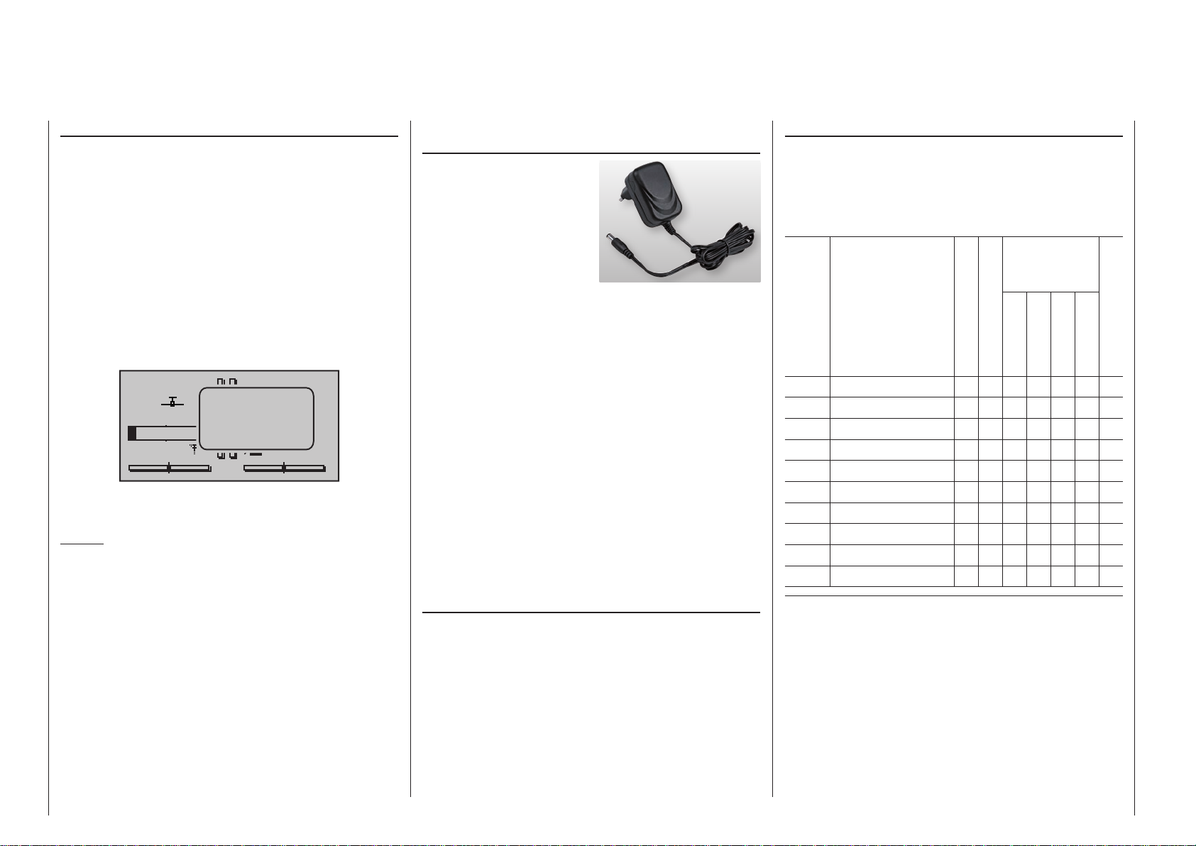
sound and the message window shown below will appear in the screen
Stp
#01
3.5V
0:22h
No later than now, operation must be terminated so
the battery can be charged again.
Notice:
Be sure that the correct battery type is set in the
“Basic Settings” menu, page 272! “Lith” must be
set as standard.
The transmitter’s rechargeable LiIo battery can be
charged by way of the charger socket located behind
a cover on the left, front side of the transmitter – as
viewed from the front – with the included plug-in
charger (order no. 32032.4), see page 22.
Batt. must
be re charged!!
x
0 00
0
T
0V
Charging the transmitter battery using the plugtype charger
With the plug-type charger
(4.2 V / 500 mA) included
in the set the charge time
for the transmitter battery is up to about fifteen
hours, depending on
the pack’s initial state of
charge.
Never use any other type or make of plug-type charger, nor a charger designed for other types of battery.
There is a risk of excessive output voltage and incorrect connector polarity (see below), either of which
can result in very serious damage. We recommend
that you label the standard charger to avoid confusion. Please read the Safety Notes on pages 8 …
9.
The transmitter must be switched “OFF” during the
entire charging procedure. Never switch on the transmitter when it is connected to the charger. Even a
brief interruption to charging can cause charging
voltage to rise to a level that will immediately damage
the transmitter with over-voltage. Also for this reason,
be sure all connectors are always plugged in securely
and have good contact.
Charging the transmitter battery via the USB socket
The transmitter is supplied fitted with a genuine
Graupner/SJ transmitter battery with integral protective circuit, Order No. 33000.1, which can also
be charged via the USB port of the
and mc- 2 0 HoTT transmitter at the usual current
available at USB ports; see “mini-USB socket” on
page 25.
C A U T I O N: charging a battery without integral
protective circuit via the USB socket incurs a serious
risk of fire!
mc-16 HoTT
Charging with automatic chargers
To achieve quicker recharging of the single cell LiIo
battery, Graupner automatic chargers can also be
used. The table below shows a selection of these
chargers.
Recommended chargers (accessory)
suitable for
battery types
Order
No. Designation
6411
6463
6464
6466
6468
6469
6470
6475
6478
6480
Charger cable, order no. 3022 is additionally needed for the transmitter and charger cable, order no. 3021 is additionally needed for
the receiver.
Other charger units and details about the listed chargers can be
found in the Graupner RC main catalog or in Internet at
www.graupner.de.
The charger socket is equipped standard with a diode
to protect against reversed polarity. Original Graupner
automatic chargers also detect battery voltage polarity.
Observe the configuration notices for the charger
used.
Ultramat 8 x x x x x
Ultramat 12 plus x x x x x x
Ultramat 14 plus x x x x x x x
Ultra Trio plus 14 x x x x x x x
Ultramat 16S x x x x x x x
Ultra Trio Plus 16 x x x x x x
Ultramat 18 x x x x x x x
Ultra Duo Plus 45 x x x x x x x
Ultra Duo Plus 60 x x x x x x x
Ultra Duo Plus 80 x x x x x x x
Input voltage 220 V
Input voltage 12 V
NiCd
NiMH
LiPo/LiIo
lead battery
integr. balancer
General operating notices
16
Page 17
First connect the charger cable’s banana plugs
to the charger and only then connect the cable’s
other end into the charging jack on the transmitter. Never allow the bare ends of the banana plugs
to come into contact with one another when the
other end of the cable is plugged into the transmitter.
Charging current may not exceed 1.5 A as otherwise the diode, and perhaps other components,
could be damaged. If necessary, limit the current
at the charger.
mc- charging jack polarity
The charger cables on the market from other manufacturers often have different polarities. Therefore use
only an original Graupner charger cable, order no.
3022.
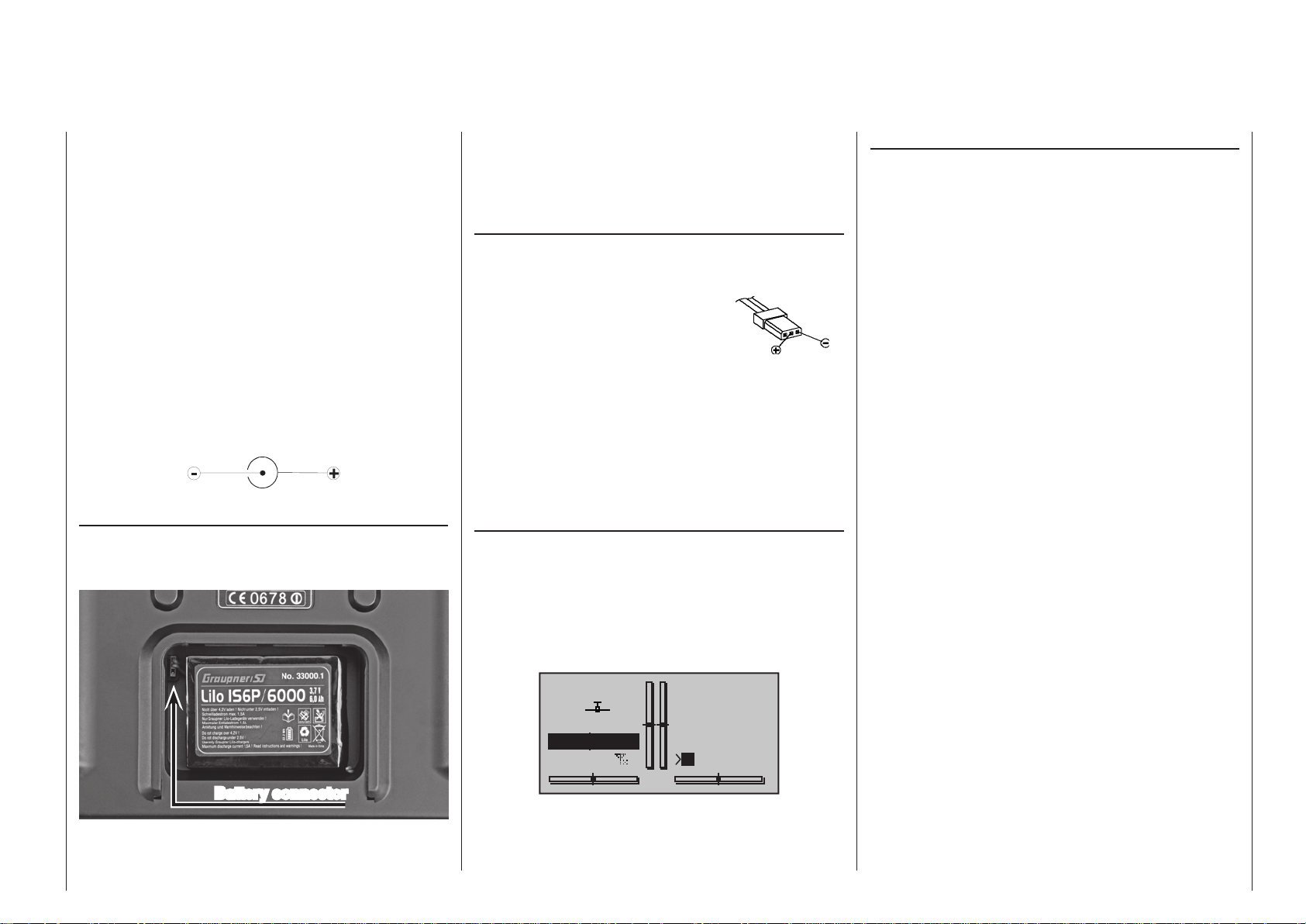
Removing the transmitter’s battery
To remove the transmitter battery locate the cover of
the battery compartment in the back of the transmitter
and slide it off in the direction of the arrow:
Battery connector
nect the transmitter battery’s connector by carefully
pulling on the supply line cable.
(The photo shows the battery of the
transmitter.)
Inserting the transmitter’s battery
The battery connector is protected against a reverse
polarity connection by two slanted edges, see illustration. When correctly plugged in, the
unconnected pin of the connector
is at the bottom, as shown in the
illustration. The plus pole (red lead)
is in the middle and the minus pole
(brown or black lead) is toward the
antenna side.
Never try to force the connector onto its circuit-board
socket.
Place the battery into its compartment and close the
transmitter’s cover.
Battery operation timer at the bottom left of the screen
This timer shows the transmitter’s cumulative operating time since the transmitter’s battery was last
charged.
This timer is automatically reset to “0:00” when the
transmitter is switched on and its battery voltage is
significantly higher than when the transmitter was last
used, e. g. because the battery was charged.
Stp
#01
4.1V
0:00h
Flt
mc- 2 0 HoTT
Transmitter
connector polarity
0:00
0:00
HoTT
Mx
0.0V
General charging notices
• The charging instructions for the charger as well
as for the battery from its manufacturer to be
observed.
• Pay attention to the maximum permissible charg-
ing current specified by the battery’s manufacturer.
In order to prevent damage to the transmitter,
charging current should never exceed 1 A. If necessary, limit the current at the charger.
• If the transmitter battery is nevertheless to be
charged at a current rate in excess of 1 A, then it is
imperative that this is done outside the transmitter.
Otherwise there is a risk of damage to the transmitter’s board due to overloading its printed circuit
paths and/or overheating of the battery.
• If an automatic charger is to be used for charg-
ing, perform several test charging procedures to
ensure the flawless functionality of its automatic
shut-off. This applies particularly if you want to
charge the standard installed Lithium battery with
an automatic charger unit. You may need to alter
the charger’s cut-off behaviour if the charger you
are using offers this option.
• Do not execute a battery discharge or battery
maintenance program through the charger jack.
The charger jack is not suitable for this purpose.
• Always connect the charger cable to the charger
first and then to the receiver or transmitter battery.
This avoids the possibility of shorting the bare
banana plug ends together.
• If the battery heats up significantly, check the bat-
tery’s condition, replace the battery or reduce the
charging current.
• Never leave a charging battery unattended.
• Follow the safety notices and handling instruc-
tions provided on page 8.
Lift one side of the battery and withdraw it from the
hook-and-loop tape without using force. Then discon-
17General operating notices
Page 18
Opening the transmitter housing
Carefully read the notices below before opening the
transmitter housing. It may be better if unexperienced
users ask a Graupner Service location to take care of
the procedures described below.
The transmitter should only be opened in the following situations:
• to convert a neutralized joystick to a non-neutralized joystick or a non-neutralized joystick to a
neutralized joystick.
• to adjust joystick return tension.
Switch off the transmitter before opening its cover.
Open the battery compartment as described on
the previous double-page. If the handrests are fitted, undo the three lower retaining screws of the six
screws in each handrest.
Now undo the five recessed screws in the back of
the transmitter and the battery well using a PH1-size
cross-point screwdriver; see illustration:
side.
Important notices:
• Ensure that the shorter screw – in the battery
well – does not fall inside the transmitter.
• Make no modifications of any kind to the circuitry as this will void the guarantee as well as
the unit‘s official permit.
This applies in particular to the switches installed on both sides of the front screen. If you
wish to change the arrangement, contact your
nearest Graupner Service Centre.
• Be sure not to touch the circuit boards with
any metallic objects. Do not touch contacts
with your fingers.
• Never switch the transmitter on when its housing is open.
When you close the transmitter again, be sure
that …
• … no cables are caught between housing edges
when the backplate is put into position.
• … both housing parts are properly seated with
one another before screwing them together. Never
force the housing sections together.
• Turn the screws down into the existing housing
threads without stripping them out.
• … fit the shorter of the five screws in the battery
compartment again.
• … reconnect the battery.
• … re-install the handrests if you wish.
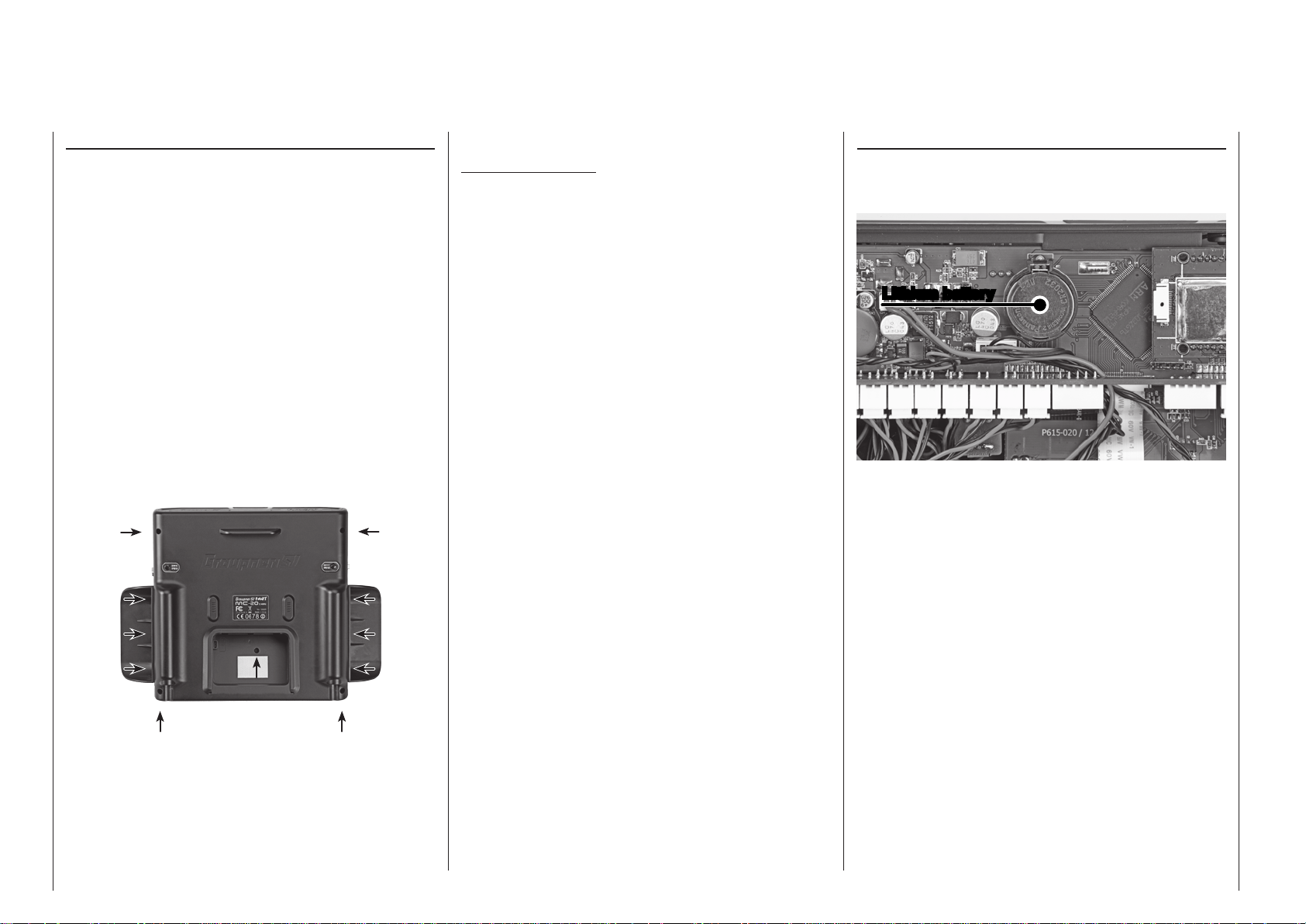
Lithium battery CR 2032
When you remove the transmitter back panel, you will
see the holder for a CR 2032 battery on the circuit
board below the aerial base, slightly left of centre:
Lithium battery
This battery maintains the date and time settings
during a transmitter power supply outage, for example
when the transmitter’s main battery is being replaced.
Note that the screw-holes are inclined slightly to the
rear, so the cross-point screwdriver should be applied
at the corresponding angle.
Hold the two housing sections together by hand then
turn the transmitter upright over a suitable surface so
these 5 screws can fall out without getting lost. Now
lift up on the backplate carefully and place it to one
General operating notices
18
Page 19
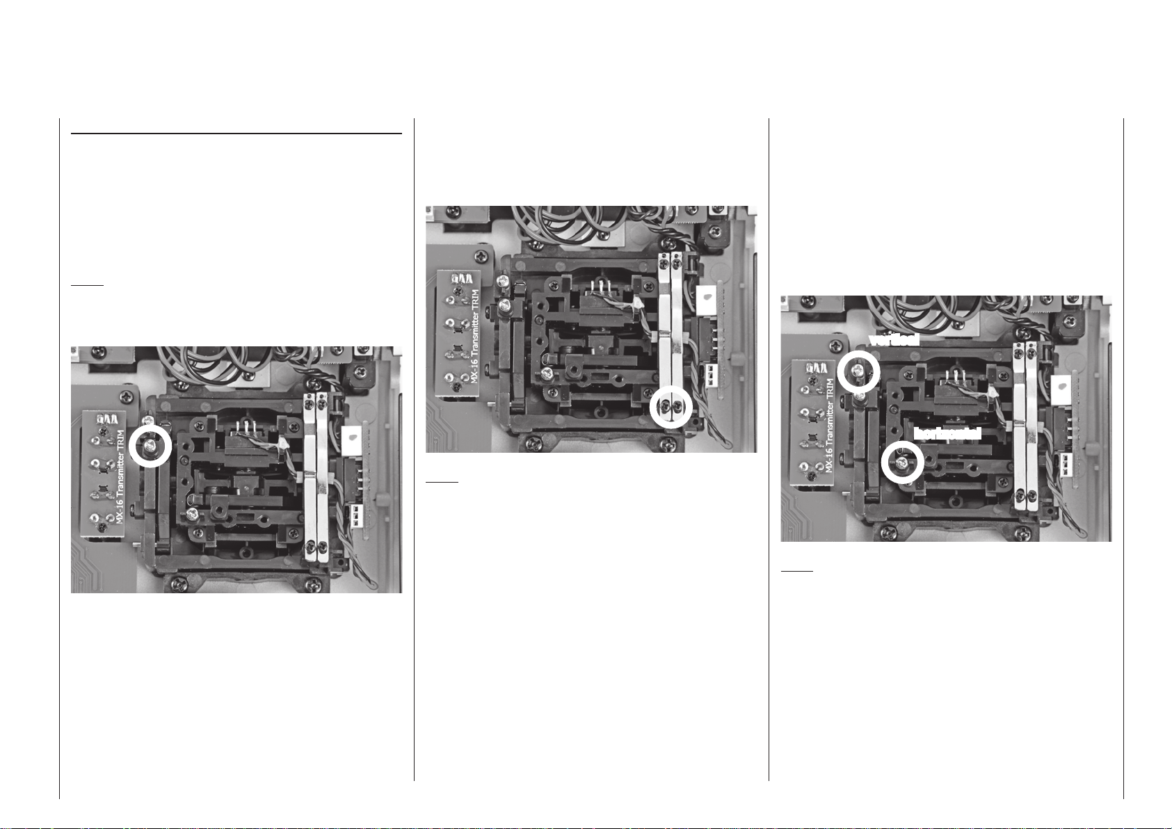
Stick conversions
Neutralization
Both the left and the right joystick can be configured
for neutralized or non-neutralized operation. Open the
transmitter.
To change the joystick’s factory setting, locate the
screw shown in the figure below enclosed in a white
circle.
Note:
The aggregate for the right joystick is a mirror image
of the left joystick so the corresponding screw for the
right joystick is on the right side just below the middle.
Brake spring and ratchet
The outboard screw of the two marked in the next
figure adjusts the braking force and the inboard screw
adjusts the strength of the ratchet for the respective
joystick:
Note:
The aggregate for the right joystick is a mirror image
of the left joystick so corresponding screws for the
right joystick are located at the top left.
Joystick restoring force
The joystick’s restoring force can also be adjusted to
the pilot’s preference. The adjustment is located next
to the return springs, see markings in the figure below.
Spring force for the given direction of motion can be
adjusted by turning the respective screw with a Phillips screwdriver.
• clockwise = stronger return,
• counter-clockwise = weaker return.
vertical
horizontal
Now turn this screw down until the respective joystick
is free to move from limit to limit – or turn the screw
out until the joystick again completely self-restoring.
Note:
The aggregate for the right joystick is a mirror image
of the left joystick so corresponding screws for the
right joystick are located to the right of the middle.
19General operating notices
Page 20

Stick length adjustment
The length of both joysticks can be continuously adjusted to adapt these transmitter controls to the pilot’s
preference.
Hold the lower half of the knurled grip in place then
turn the upper section to release its counter-locked
threads:
Now pull up or push down on the joystick’s end to the
desired length. When the length is suitable, tighten
the counter-locked threads of the upper and lower
sections again.
The procedure is the same if you wish to replace the
short stick-tops with the longer ones also supplied in
the set.
Transmitter neckstrap support bars
As standard the
mc- 2 0 HoTT transmitter set in-
cludes a strong support system for the attachment of
a neckstrap. The mc-16 HoTT transmitter can be
retro-fitted with the transmitter support system, Order
No. 33012.2, at any time.
The support bars are inserted in the sockets in the
transmitter case, and locked in place. After the transmitter has been used, they can be removed again in
similar fashion:
first press,
then turn
The support bars are installed as follows: push one
of the bars into the socket in the transmitter case,
angled towards the centre of the transmitter as shown
above. Now ensure that the retaining pin attached to
the bar is in line with the slot in the socket, and press
the bar against the spring in the direction of the transmitter for a distance of about one centimetre. At the
same time fold the bar outwards (do not use force) in
order to lock it in place. Install the second support bar
in the same manner.
To remove the support bars first unlock one of the
bars by lightly pressing it inwards, and then fold it
towards the centre of the transmitter. As soon as the
retaining pin is free, you can withdraw the support bar
from its guide. Repeat the procedure with the second
support bar.
The following straps are available as accessories:
Order no. Description
71.26 Transmitter straps, Graupner/SJ HoTT
72.40 Transmitter straps, deluxe
General operating notices
20
Page 21
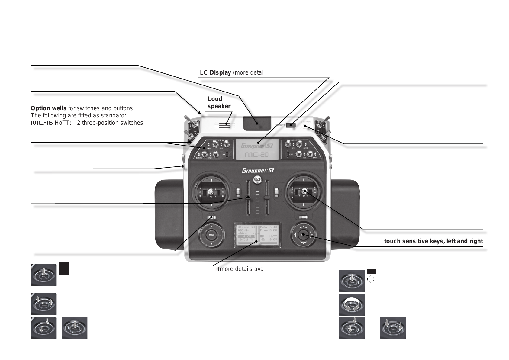
Transmitter description
Front side
(The illustration shows the mc- 20 HoTT transmitter.)
Integral aerial inside case
Connector sockets
on the face side, protected by a cover, see beginning
page 22
LC Display (more details available on page 28.)
ON/OFF switch (ON/OFF with LED display)
Hold the ON/OFF switch pressed in for about one
second to switch the transmitter on. Hold it pressed in
for about three seconds to switch off.
Option wells for switches and buttons:
The following are fitted as standard:
mc-16 HoTT: 2 three-position switches
mc- 2 0 HoTT: 12 switches of various type and 2
INC/DEC buttons
Function module
rotary control: left side “Lv1”,
right side “Lv2”
Function module
two sliders “Sl1” and “Sl2”
Digital trim
For the fine-tuning of servo positions (travel
neutralization). Each click produces an increment of adjustment (position indicator in
display). The trim increment can be selected
in the »Stick settings« menu.
left four-way button:
ESC = select/confirm
ESC touched for about 1 s: Changeover between
telemetry menu and basic display
= scroll in one of the four directions with every
tap (, , , )
simultaneous horizontal tap ()
= changeover between basic display and servo
display
simultaneous vertical tap of the left
+
() keys + "SET" of the right fourway button = changeover to the "secret
options", see page 34.
Loud
speaker
mc-2 0
LC Display (more details available on page 28.)
Contrast adjustment in the »General settings«
menu; see page 271.
Warning indicators:
• for underrun of preset battery voltage threshold
• for fault function of the teacher/pupil system
• C1 joystick too far toward full throttle when transmitter is switched on
• …
LED indicators
BATTERY: illuminates when voltage is sufficient
RF: illuminates during RF radiation
WARNING: blinks, for example, when "Throttle too
high", "no pupil signal", "Transmitter
battery voltage too low", …
Joystick
Two joysticks for a total of four independent
control functions. The length of the joysticks
can be adjusted. The correlation of control
functions 1 … 4 can be set on a model
type basis by way of the »Basic settings,
model« menu, e. g. throttle left or right. The
throttle joystick can be converted from neutralizing to non-neutralizing, see page 19.
touch sensitive keys, left and right
right four-way button:
SET = select/confirm
= scroll or change value with every touch of one
of the four direction
symbols (, , , )
Circle with the finger around the circumference
= scroll/change values. Alternative values selec-
tion with the left four-way button (, , , )
or
simultaneous tap on
or = CLEAR
Transmitter description - Front side
21
Page 22

Face-side connections
Charger socket
(The illustration shows the mc- 20 HoTT transmitter.)
The left-hand side flap provides access to the charge
socket of the
transmitter:
The transmitter’s rechargeable LiIo battery can be
charged by way of the charger socket located behind
a cover on the left, front side of the transmitter – as
viewed from the front – with the included plug-in
charger (order no. 32032.4).
Maximum permissible charging current with Graupner
automatic chargers: 1,5 A.
Never use plug-in chargers from other manufacturers
or chargers intended for other battery types. Charger
output voltage which is too high or possibly even
different plug polarity, see further below, can cause
immense damage.
More information about charging the transmitter’s
battery can be found on page 16. Observe the
safety notices beginning on page 8 when handling
lithium batteries.
Transmitter description - Face-side connections
22
mc-16 HoTT and m c- 20 HoTT
DSC jack
The acronym “DSC” is a carryover which stands for
the original “Direct Servo Control” function. However,
in HoTT systems the “direct servo control” function is
no longer available via a diagnose cable due to technical reasons.
Once the left-hand side flap has been moved away,
the DSC socket is accessible:
The two-pole DSC socket fitted as standard to mc-
16 HoTT and mc-2 0 HoTT transmitters serves
both as Trainer socket (Teacher and Pupil) and also
as interface for flight simulators and external RF
modules.
To ensure a proper DSC connection, please observe:
1. Make any necessary menu changes.
Refer to the section beginning on page 222 to
adapt the transmitter to a teacher/pupil system.
2. When operating a flight simulator or when operating the transmitter as a pupil transmitter, ALWAYS
switch OFF the transmitter as only in this position
does the transmitter‘s RF module remain inactive
after the DSC cable is inserted. This also reduces
the transmitter‘s power consumption somewhat.
Only the red “
constantly illuminated and the transmitter’s ba-
Battery
” LED should remain
sic display should show the character string “DSC”
below the operating time clock. At this time, the
display of telemetry data and symbols will be suppressed.
ELEVE
#11
4.1V
0:01h
The transmitter’s upper display will show the message “CANNOT RECEIVE DATA” during this time.
Thus the transmitter is ready for operation.
In contrast, the transmitter in teacher mode is to
be switched on prior to plugging in the respective cable.
3. Connect the other end of the cable to the desired
unit in compliance with the given operating instructions for that unit.
Important:
Pay attention that all plugs are inserted se-
curely into their respective sockets and use
only the prescribed 2-pole TRS connector
plugs on the DSC-side.
4. In the line „DSC Output“ in the »Basic settings,
model«, page 92 or 100, – depending on the
number of functions transferred – one of the following modes can be set: PPM10, PPM16, PPM18 or
PPM24. Default setting: PPM10.
Notice about flight simulators:
Because of the myriad of flight simulators available on
the market, it may be necessary to have the contact
layout of the audio plug or DSC module appropriately
modified by Graupner Service.
Stp
Flt
DSC
0:00
0:00
HoTT
Page 23
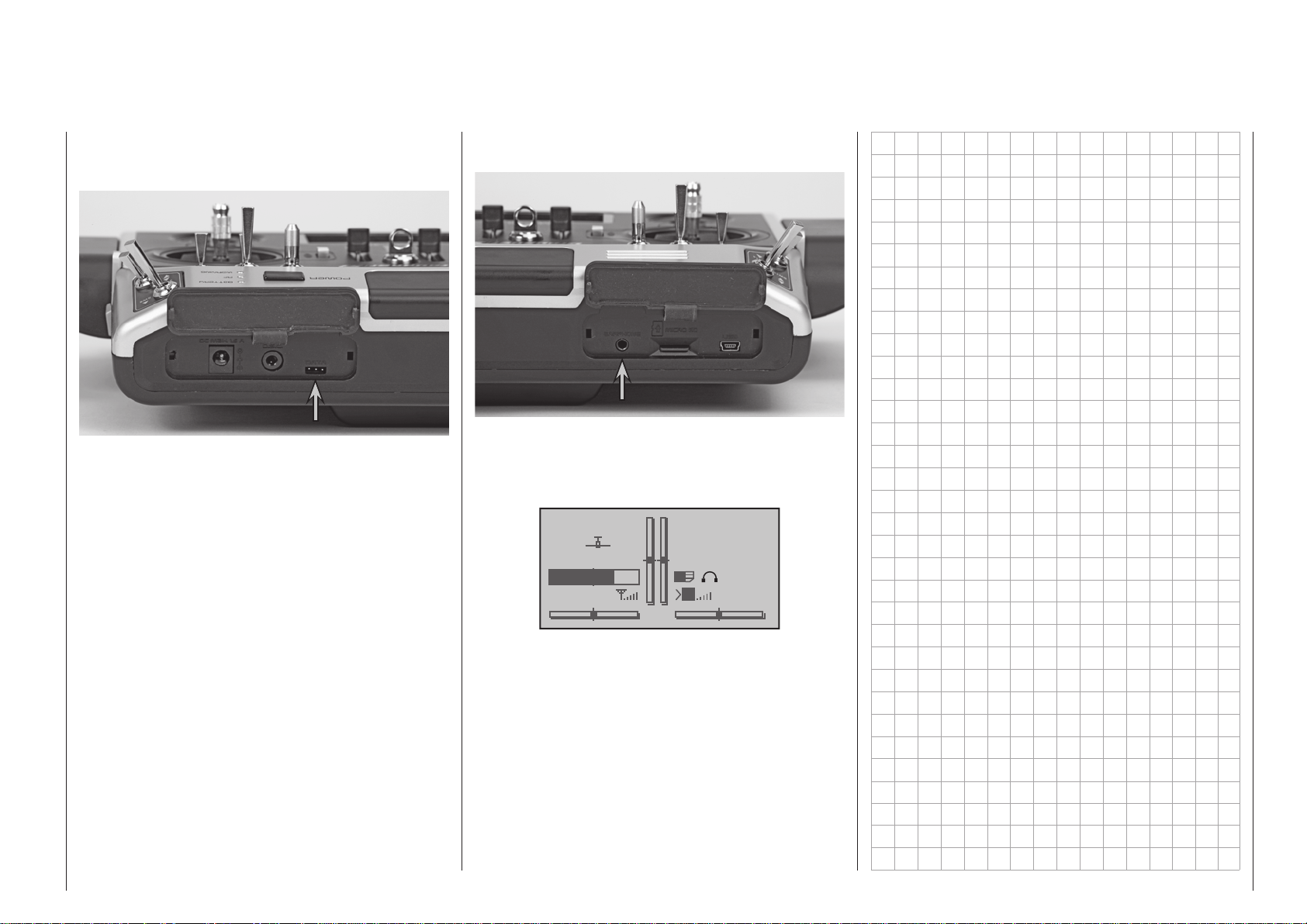
Data jack
Headset connector
The left-hand side flap provides access to the DATA
socket of the
transmitter:
This jack is intended for connection of the optional
Smart-Box, order no. 33700.
Details about the Smart-Box can be found with the
given product in the Graupner RC main catalog or in
Internet at www.graupner.de.
However, the Data socket can also be used to connect external RF modules made by other manufacturers; see “EXT.” and “SP.” in the “Module” section of
the “Basic model settings” menu on pages 88 and
96.
mc-16 HoTT and m c- 20 HoTT
Once the right face-side cover has been moved away,
the transmitter’s headset connector is accessible:
The jack is intended for connecting conventional earplugs or a headset by way of a 3.5 mm TRS plug. (not
included in the set) An appropriate symbol will appear
in the basic display when a headset is connected:
Stp
#01
3.9V
2:22h
The transmitter’s acoustic signals as well as those
signals associated with the telemetry menu are output via this connection. These announcements are
made in German language by default. More about
this can be found under “Voice output” in the section »SECRET MODE« beginning on page 34 and
»Telemetry« beginning on page 240.
The volume of signals and voice output sent to the
headset can be adjusted individually in the lines
“Voice volume”, “Vario volume”, and “Beeps volume”
of the »General basic settings« menu, page 268.
Flt
M
0:00
0:00
HoTT
5.5V
23Transmitter description - Face-side connections
Page 24
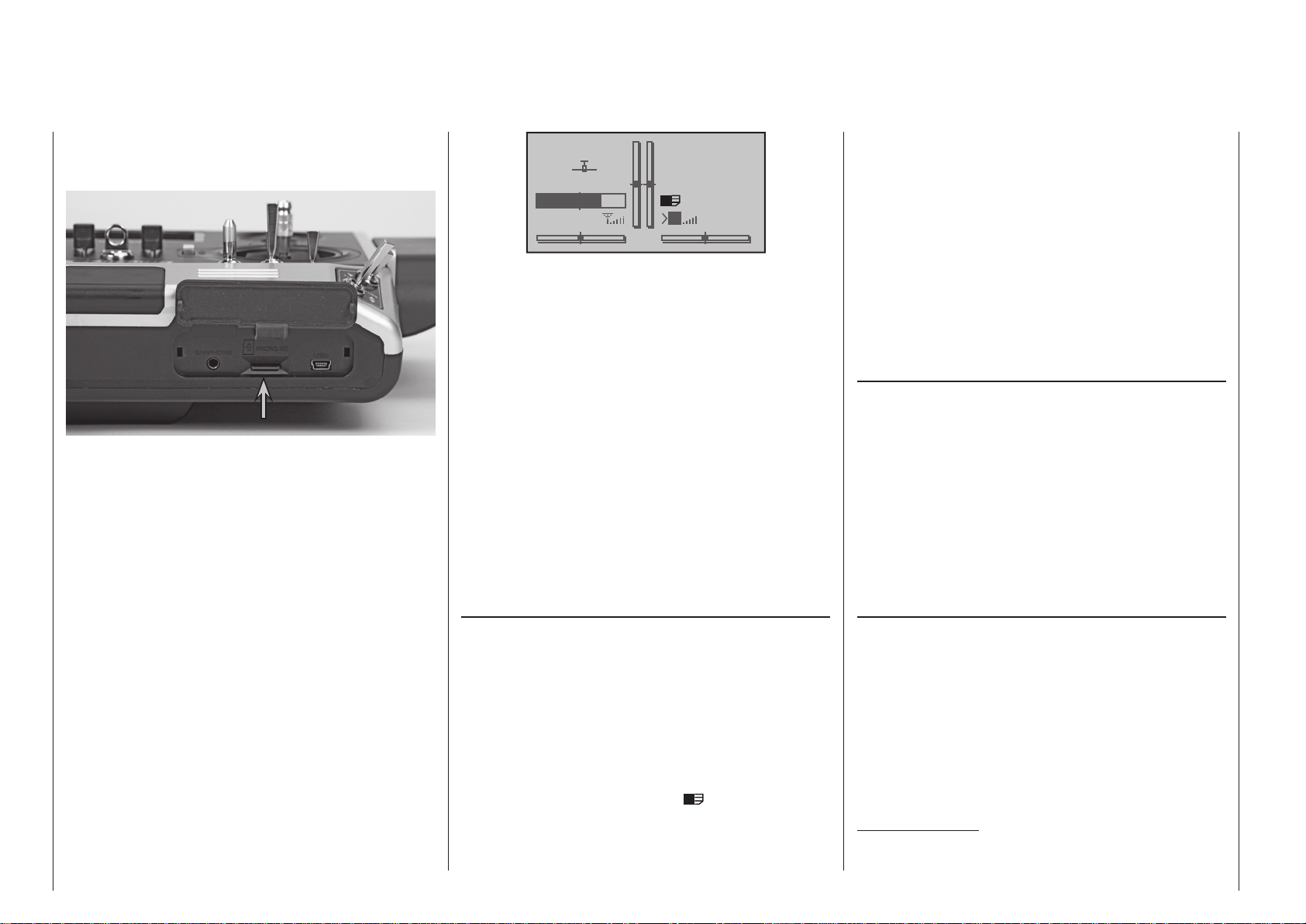
Card slot
micro SD and micro SDHC
The transmitter’s card slot for type micro-SD and
micro-SDHC memory cards becomes accessible
once the right face-side cover has been turned away.
Although a memory card is supplied as standard, the
slot also accepts any standard commercial micro-SD
memory cards of up to 2 GB capacity and microSDHC cards of up to 32 GB capacity. However, as
a manufacturer we recommend the use of memory
cards no larger than 4 GB as this is completely adequate for all normal situations.
The type of memory card to be used in the transmitter
is that known in conjunction with digital cameras and
cell phones. It is to be pushed into the slot, contacts
up, until it latches, see photos above. Once the memory card has been inserted, the transmitter’s cover
flap can be closed again.
If the standard memory card is inserted – or another
card which has already been inserted in the transmitter at least once – then the card is immediately ready
for use when the transmitter is switched on. When the
transmitter is switched on again after inserting such
a card, the stylised memory card icon appears in the
base display:
Transmitter description - Face-side connections
24
Stp
#01
3.9V
2:22h
If the card has not previously been inserted, the
transmitter first creates a number of folders on it;
this is indicated in the transmitter’s base display by
a card symbol which slowly fills from left to right. The
memory card is ready for use as soon as this animation ceases.
You can remove the prepared memory card from the
transmitter when required, and insert it in a suitable
card reader. Connect the reader to your PC or laptop,
and copy the files – previously downloaded from the
Download page for your transmitter – into the appropriate folder. Now remove the memory card from your
card reader and insert it in the transmitter once more.
Removing the memory card
Press the SD or SDHC card a bit further into the
card slot to release the slot’s latch then pull out the
memory card.
Data acquisition / storage
The storage of data on the SD card is coupled to the
flight timer. If this timer is started – when a suitable
memory card is inserted in the card slot and a telemetry link to the receiver exists – data acquisition is
also started. Data acquisition will stop again when the
flight timer is stopped. The flight timer is started and
stopped as described in the section »Timers (gen-
eral)” on page 162.
The amount of data written on the memory card is
presented as a black bar graph (
from left to right as data fills the memory card .
After a data acquisition session is finished, there will
be an (empty) folder “Models” and a “LogData” folder
Flt
M
0:00
0:00
HoTT
5.5V
) which grows
on the memory card. Within the “LogData” folder there
will be log files, that are designated with names in the
format 0001_year-month-day.bin, 0002_year-monthday.bin, etc., in sub-folders named “model name”. If
a model memory is still “unnamed” the respective log
files can be found in a sub-folder designated “NoName” when the memory card is removed from the
transmitter and inserted into the card slot of a PC or
laptop. There is a PC program available on the transmitter’s download web page at www.graupner.de with
which the stored data can be evaluated on a compatible PC.
Importing voice files
As mentioned in section “Headsets”, here at the right,
the transmitter’s acoustic signals as well as those
signals and announcements associated with the »Telemetry« menu can be output by way of the headset
connector. These announcements are made in German language by default. These announcements are
summarized in a voice packet which is stored in a
transmitter-internal memory but can be replaced by a
voice packet of a different language at any time. More
information about this can be found in the section
»SECRET MODE« beginning on page 34.
Transmitter firmware updates
The transmitter firmware can be updated and – if
necessary – replaced at this menu point, using the
procedure described in the previous section entitled
“Importing voice files”; the screen language can also
be changed here. For more details of this please refer
to the section entitled “SECRET MODE” which starts
on page 34.
Updates and more information can be found on the
product page for your specific HoTT transmitter; see
the Download section at www.graupner.de.
Important notes:
• No claim can be considered unless a log file is
present; see left under “Data recording / stor-
Page 25
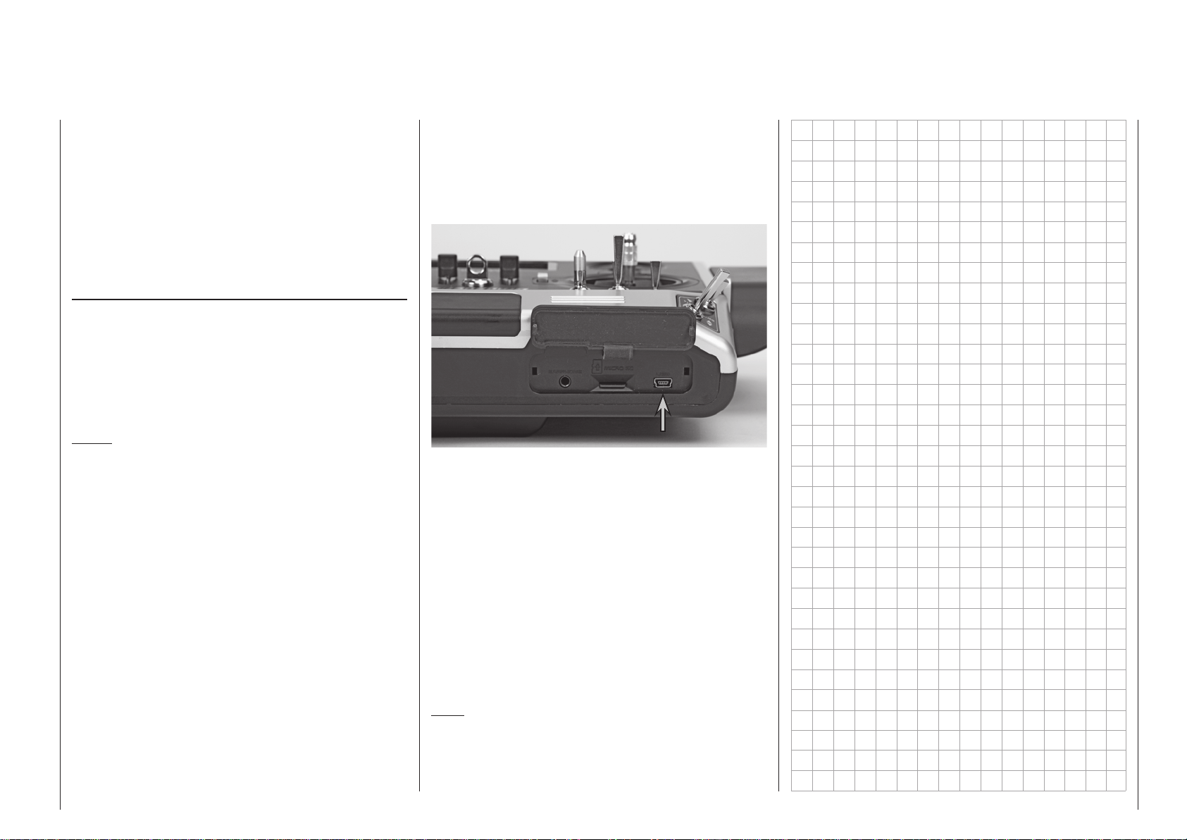
Mini-USB connector
ing”.
• For the same reason the transmitter must always be updated to the latest software status.
• It is essential that you register at https://www.
graupner.de/en/service/product_registration.
aspx to ensure that you are constantly informed of important software updates. This is
the only means by which we can automatically
keep you aware of new updates by e-mail.
Importing/exporting model memories
Any model memory can be stored to an inserted
memory card or from an inserted card into the transmitter. This feature is intended to support data exchange between identical transmitters or even use
as data backup. More information about this can be
found in the section »Copy / Erase« beginning on
page 80.
Notes:
• Some special symbols that can be used in model
names are subject to specific restrictions associated with the FAT or FAT32 file system used by the
memory cards and these special symbols will be
replaced during the copy process with a tilde (~).
• In principle the model memories of the mx-20 and
mc- 2 0 transmitters are compatible, BUT:
If you wish to carry out an “Import from SD card” in
the other transmitter you must first copy or move
the appropriate model memory to the appropriate
folder on a PC. For example: from \\Models\mc-20
to \\Models\mx-20, or vice versa.
See page 82 for more information on “Import
from SD card”.
C A U T I O N :
After you have carried out an “Import from SD
card” it is absolutely essential to check all the
model functions with great care. Note also that the
transmitter control and switch functions may need
to be adjusted to suit the new transmitter.
The right-hand side flap of mc-16 HoTT and mc-
20 HoTT transmitters provides access to the soft-
ware update socket, which is also used for altering
the date and time via a PC using the Windows XP,
Vista or 7 operating system; this socket is located on
the right-hand side under the flap:
The USB cable, order no. 32032, which is included
with the set is to be connected to this jack. The procedure for carrying out a software update via a PC is
described on page 50.
The PC software required, as well as the suitable
USB driver, can be found on the download page for
the given product on the Graupner website at
www.graupner.de.
Once the necessary driver and software is installed
on the PC, this USB connection can be used to update the transmitter or even just to set the transmitter’s date and time. To set the transmitter’s date and
time by way of this jack, refer to the »Info display«
menu, beginning page 278.
Note:
mc-16 HoTT and m c- 20 HoTT transmitters can
also be charged using this USB socket at the standard currents present at USB ports; see page 16.
25Transmitter description - Face-side connections
Page 26
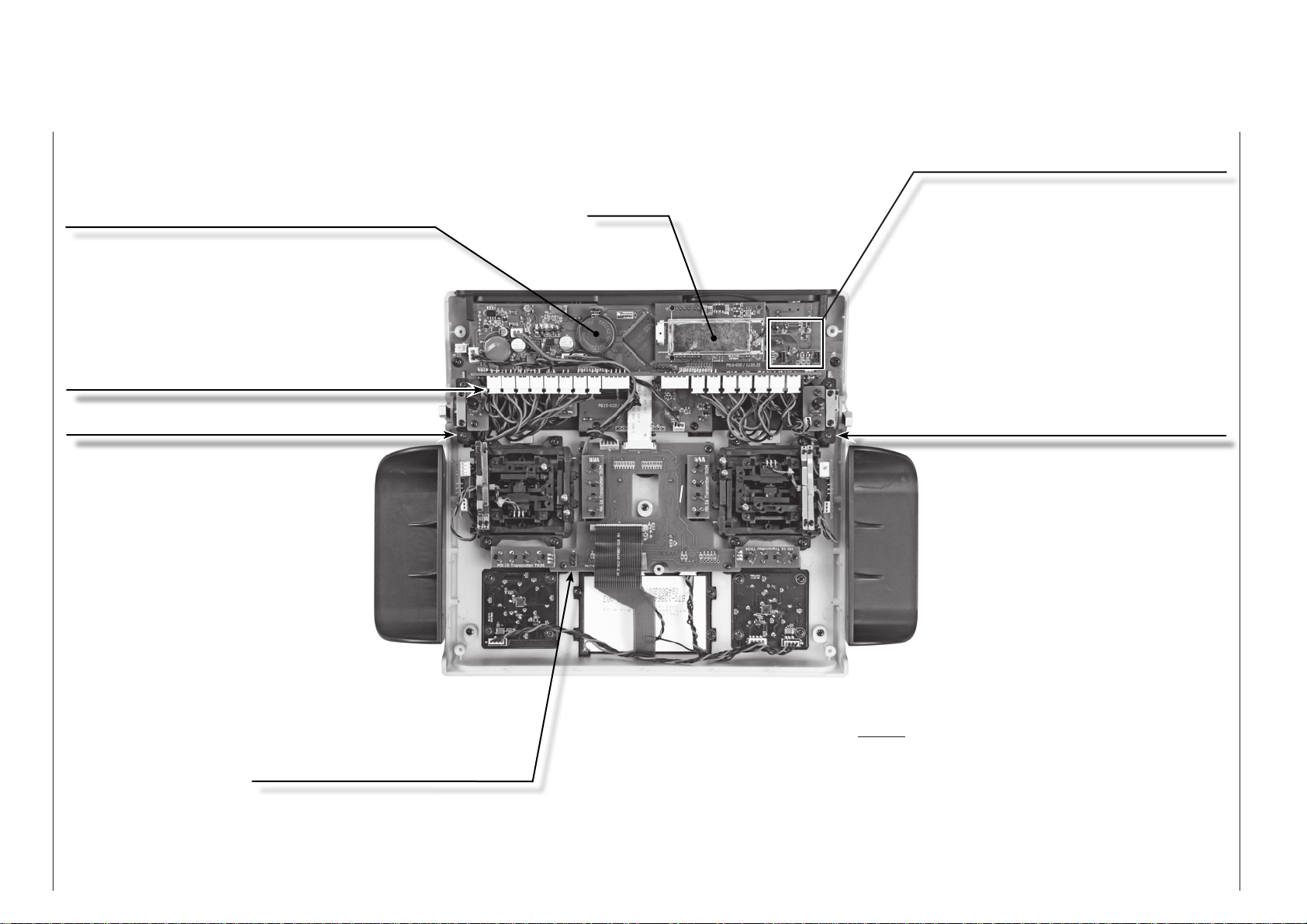
Bottom side transmitter interior
(The illustration shows the mc- 20 HoTT transmitter.)
Lithium battery CR2032 (not rechargeable)
Independent backup for the transmitter's date
and time settings, see »Info display« menu on
page 278.
Sockets for optional transmitter controls and
switches
(In principle you can connect the switches in any
order, but we strongly recommend that you maintain the same sequence as the case legends to
avoid confusion.)
Socket for optional Bluetooth module
Order No. 33002.5
RF modul
SW16/PB18 (when transmitter is closed),
see “Physical control, switch and control
switch assignments” on page 68
Transmitter battery plug
For charging the battery and a list
of suitable automatic chargers, see
page 16
Transmitter description - Bottom side transmitter interior
26
SW17/PB19 (when transmitter is closed),
see “Physical control, switch and control
switch assignments” on page 68
Notes:
Disconnect the transmitter battery at its connector when performing any type of work inside the
transmitter. Never allow solder points to come
into contact with objects as this can create short
circuit conditions.
All jacks and plugs not described are to be left
unconnected.
Page 27

27For your notes
Page 28
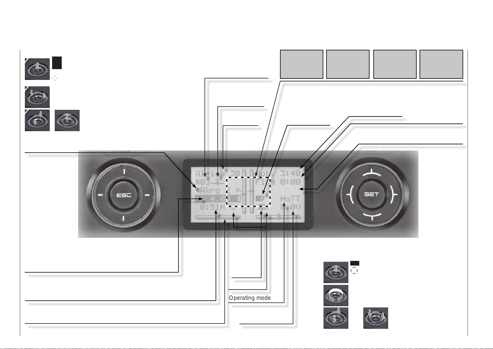
Display and keypad
(The illustration shows the control pad of the mc- 20 HoTT transmitter.)
left four-way button:
ESC = select/confirm
ESC touched for about 1 s: Changeover between
telemetry menu and basic display
= scroll in one of the four directions with every
tap (, , , )
simultaneous horizontal tap ()
= changeover between basic display and servo
display
simultaneous vertical tap of the left
+
() keys + "SET" of the right fourway button = changeover to the "secret
options", see page 34.
Flight phase name
see menu »Phase settings«, page 152 or 156
Model memory location
mc-16: 1 … 20
mc- 2 0 : 1 … 24
Model type indicator
winged model, helicopter
Model name
No
pupil
signal!
Throttle
too
high!
Batt. must
be re-
charged!!
Fail Safe
setup
A selection of potential warnings and notices. More about this on
page 33.
Stopwatch in min:s
micro-SD card
inserted
(upward/downward)
Flight timer in min:s
Flight phase timer display, if available;
see “Flight phase timers”, page 166.
t.b.d.
Transmitter battery voltage with dynamic bar indicator. If the
lithium battery voltage underruns the 3.60 V (adjustable)
threshold a warning message will appear and an acoustic
warning will sound. (Switchover for NiMH batteries.)
Transmitter operating time. This will automatically be reset to zero after a
charging process.
Display diagram for all four digital trim levers with numeric indicator and
direction indicator
Transmitter description - Display and keypad
28
M = Model
operation
P = Pupil
(pupil
transmitter)
Signal strength
Operating mode
Receiver battery
voltage RX-SPG
right four-way button:
SET = select/confirm
= scroll or change value with every touch of one
of the four direction
symbols (, , , )
Circle with the finger around the circumference
= scroll/change values. Alternative values selec-
tion with the left four-way button (, , , )
or
simultaneous tap on
or = CLEAR
Page 29
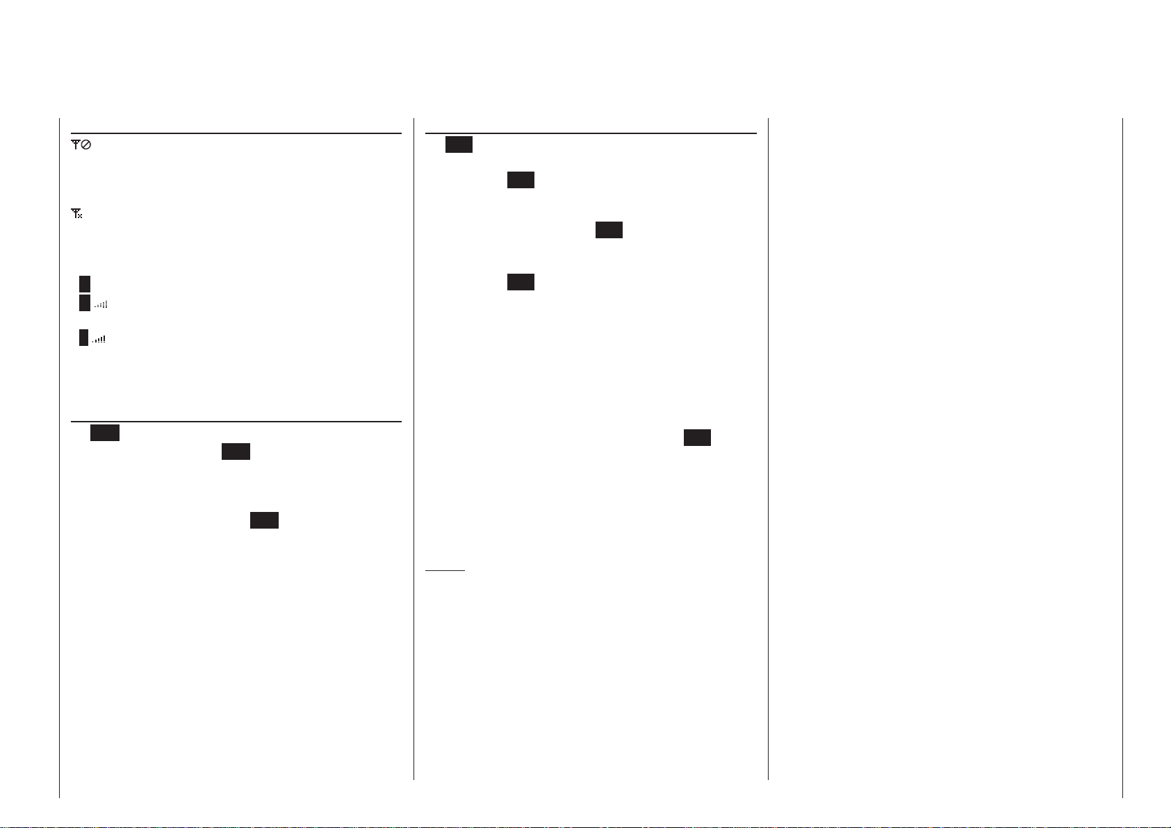
Operating the “data terminal“
Entry keys ESC and SET
Display symbols
Displayed telemetry symbols
the active model memory has not yet been
“bound” to a HoTT receiver. More about the
“Binding” process can be found on page 87
or 95.
Switched off on RF transmitter side
blinking antenna symbol:
The last receiver bound to the active model is
inactive or out of range
>M x no telemetry signal to receive
signal strength indicator of the connection to
>M
the model
signal strength indicator of the connection to
>P
the pupil transmitter in the display of the teacher transmitter for wireless teacher/pupil operation
Keys left of the display
• ESC key
each brief tap on the ESC key will cause a step-
wise return in function selection or even further to
the base screen. Any changes made to settings
remain.
Momentarily touching the ESC key for about 1 s
while in the base screen will open and close the
»Telemetry« menu.
• Selection keys
1. A tap on one of these keys will scroll, appropri-
ate for the given arrow direction, through lists,
such as through the model selection list or the
multi-function list or within menus though the
menu‘s lines.
2. A brief simultaneous tap on the keys will
cause a switch from the transmitters base
screen, as well as from almost any menu position, into the »Servo display« menu.
Keys to the right of the display
• SET key
1. After switching the transmitter on, a brief tap
2. Within menus having settings, activate / deacti-
• Selection keys
1. “Leafing through” the multi-function menu, and
2. Select or set parameters in setting fields af-
3. A brief simultaneous tap on the or
Notes:
• In contrast to the four-way buttons of the
HoTT transmitter, which are “pressed” in the same
way as micro-switches, the touch-sensitive CapTouch buttons of the mc-2 0 HoTT respond to
the lightest of touches.
• Touching the given four-way button does not itself
initiate the given action but rather the end of the
touch.
• In the event the four-way buttons do not exhibit any functionality immediately after switching the
transmitter off and then on again right away, this
is not a fault. Just switch the transmitter off again
on the SET key will cause a jump from the displayed base screen to the Multi-function menu.
In the same manner, a selected menu can now
be called up with the SET key.
vate (confirm) the given setting fields with a tap
on the SET key.
the menu lines within the set-up menus, in the
same manner as the Select buttons of the lefthand four-way button, or – on the
transmitter – in the same manner as “circling”
over the four Select buttons.
ter their activation with a tap on the SET key,
whereby the and keys will have the
same given function. In this case it is completely irrelevant which of these two keys are used.
keys will set a changed parameter value in the
entry field back to its default value (CLEAR).
mc- 2 0
mc-16
then wait for several seconds before switching it
on again.
29Transmitter description - Operating the “data terminal“
Page 30
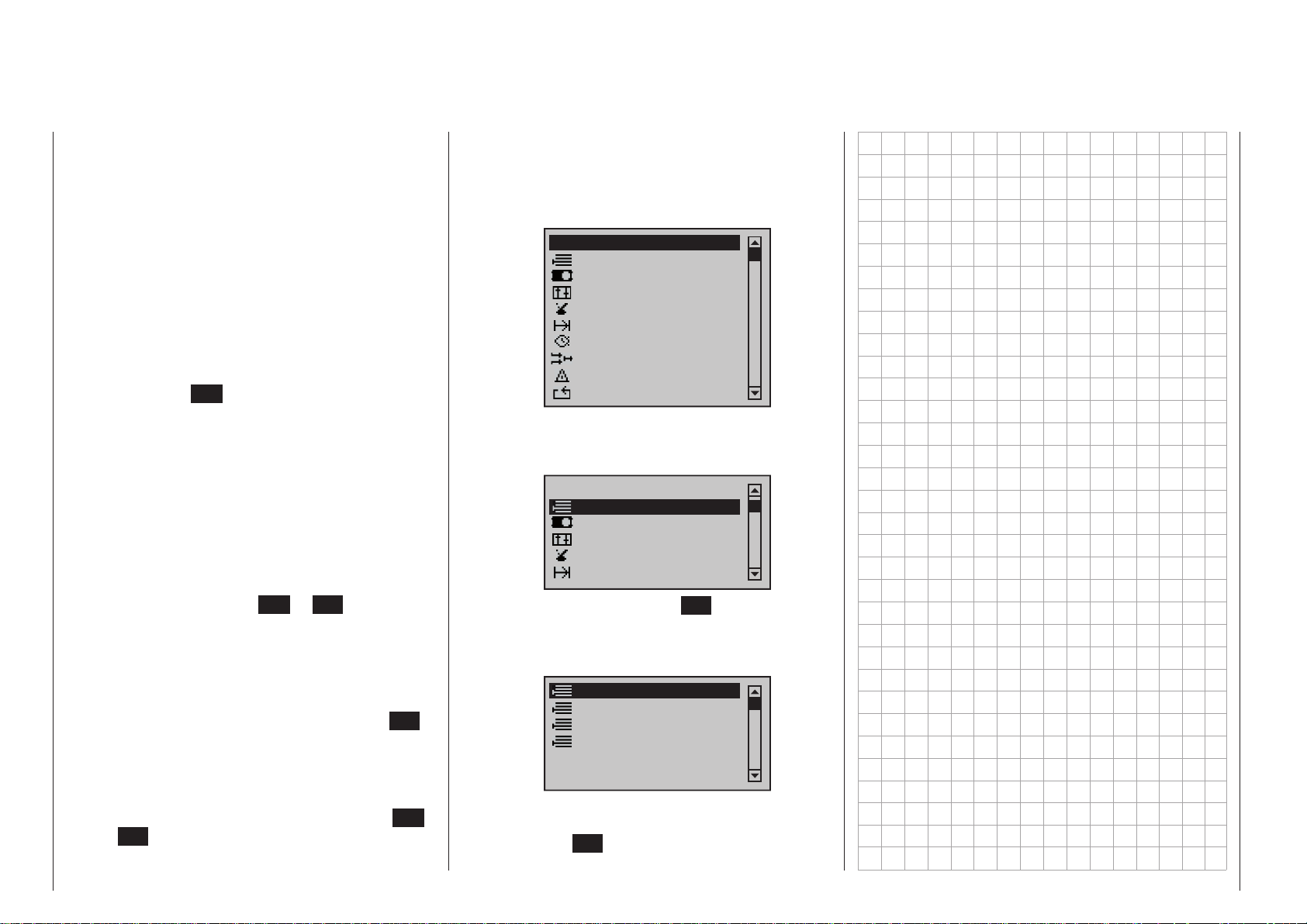
Shortcuts
The following key combinations can be used to directly call up certain menus and options:
• CLEAR
A brief simultaneous tap on the or keys
of the right four-way button will reset a changed
para meter value in the active entry field back to its
default value.
• »Servo display«
A brief simultaneous tap on the keys of the
left four-way button will change from the transmitter’s base screen or from almost any menu position to the »Servo display« menu, see page 274.
• »Telemetry« menu
Tap the center ESC key of the left four-way but-
ton for about 1 s to call up the »Telemetry« menu
from the transmitter’s base screen or return to the
base screen again, see text beginning on page
228.
• Graphic display of telemetry data
Briefly touching one of the selection keys of the
left or right four-way button will cause a jump from
the base screen directly to the transmitter’s graphic display of telemetry data or will allow paging
back and forth between individual graphic displays.
A brief tap on the center ESC or SET key will
cause a return back to the base screen.
• »SECRET MODE«
(Language selection, Firmware update, Stick
calibration etc.)
Touch and hold the selection keys of the left
four-way button then momentarily touch the SET
key of the right four-way button, see text beginning
on page 34.
• Entry lockout
Entry lockout is activated and deactivated from the
base screen by simultaneously touching the ESC
and SET keys for about 2 s.
• Quick-Select
Transmitter description - Shortcuts
30
From the multi-function list, a jump can be made
into a “Structure overview” by way of a brief, simultaneous tap on the or keys of the
right four-way button. Menus are arranged in clear
groups in this overview.
All menus
Memory
Servo setting
Transm. controls
Switches
Flight phases
Timers
Mixers
Special. funct.
Global functions
Now the desired group can be selected with the
selection keys of the left or right four-way button …
All menus
Memory
Servo setting
Transm. controls
Switches
Flight phases
… then finally tap the center SET key of the right
four-way button briefly. As soon as the key is released, only the respective generic term for the
given menu will remain listed. For example:
Model select
Copy / Erase
Suppress menus
Suppress models
Now you can select the desired menu point using the or buttons, and then call it up by
pressing the SET button of the right-hand four-way
button.
Page 31
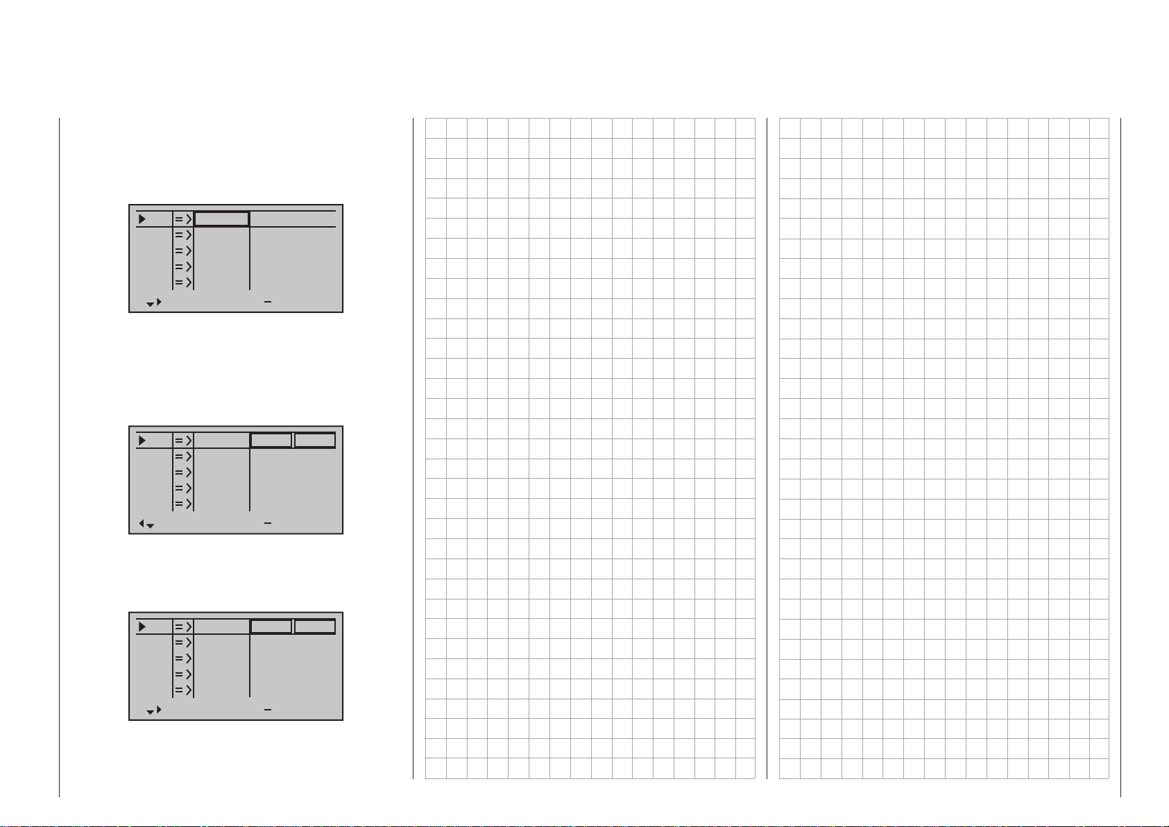
Concealed menu columns
Some menus have concealed columns to improve
legibility. Menus with concealed columns can be recognized by virtue of a triangle pointing to the right in
the bottom left corner of the screen. For example, in
the menu »Servo settings«:
S1
S2
S3
S4
S5
Rev cent
In this menu, e. g. the column “- lim +” (servo travel
limit) to the right of column “- travel +” is “concealed”.
To reach this column, use the pointing triangle at the
bottom left of the screen to push the frame marker
with the arrow key of the left or right four-way button to just beyond the column for “- travel +”:
S1
S2
S3
S4
S5
Rev cent
To again return to the now-concealed column “- travel +” or even further to the left, push the frame marker
with arrow key of the left or right four-way button
appropriately to the left:
0%
0%
0%
0%
0%
0%
0%
0%
0%
0%
100%
100%
100%
100%
100%
150%
150%
150%
150%
150%
100%
100%
100%
100%
100%
trv
150%
150%
150%
150%
150%
lim
+
+
S1
S2
S3
S4
S5
Rev cent
This procedure is analogous for the other menus.
0%
0%
0%
0%
0%
100%
100%
100%
100%
100%
100%
100%
100%
100%
100%
trv
+
31Transmitter description - Concealed menu columns
Page 32
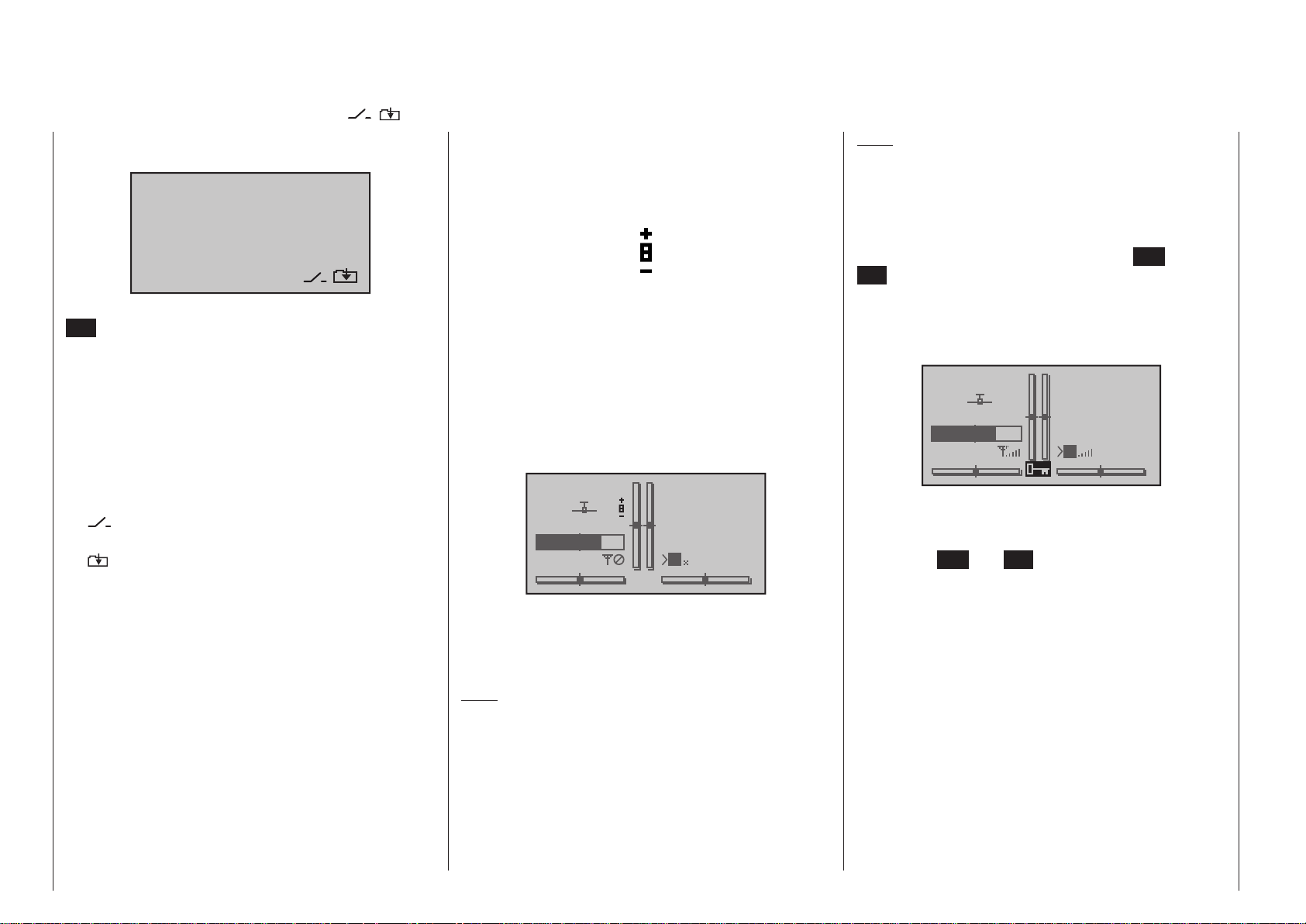
Function fields in the display
Position indicator
Entry lockout
CLR, SEL, STO, SET, SYM, ASY, POS, ,
Depending on the given menu, certain function fields
will appear on the bottom display line:
CLR SEL STO SYM ASY
A marked function is activated with a tap on the
SET key.
Function fields
• CLR (clear) erase
• SEL (select) selection
• SET (set) “set” or adjust a value
• STO (store) store (e. g. control position)
• SYM set values symmetrically
• ASY set values asymmetrically
• POS Only in »Trim memory« menu
switch field symbol (assignment of
•
all types of switches)
within a menu, change to the sec-
•
ond page, (menu continuation)
INC/DEC buttons CTL 5 and 6
When you operate one of the two INC/DEC buttons
CTL 5 + 6, which are fitted to the two switch boards of
the mc- 2 0 HoTT transmitter only, a small symbol
appears on the left of the screen adjacent to the two
vertical position indicators:
At the same time, for the duration of the control‘s operation, the position indicator for the two vertical bars
in the middle will change from displaying current trim
position to a display of the respective current position
of the controls CTL 5 & 6.
Logically, the left control (CTL 6) is displayed by the
left bar indicator and the right bar indicator displays
the position of the right control (CTL 5). The two horizontal bars continue to show current trim positions of
respective stick trim controls:
0:00
0:00
HoTT
#01
2:22h
Stp
Flt
3.9V
M
Note:
This option is only available as standard on the mc-
20 HoTT transmitter, but can be unlocked on the
mc-16 HoTT transmitter at extra cost.
A lockout for the touch keys, and thus protection
against inadvertent use of all setting options, can be
established by touching and holding the ESC and
SET keys simultaneously for about two seconds while
the transmitter is in its basic display. This lockout
condition is indicated by a key symbol, located at the
intersection point of the trim bars, which is displayed
in reverse video.
Stp
#01
3.9V
2:22h
The lockout is effective immediately but controls remains operationally ready.
This lockout can be removed by again touching and
holding the ESC and SET keys for about two seconds.
Flt
M
0:00
0:00
HoTT
5.5V
About 2 seconds after operating one of the controls
has ended, the display will again revert to display of
current trim positions of the four trim controls generated by the two sticks.
Note:
On the
buttons can be retro-fitted by your local Graupner
Service Centre at extra cost.
T ransmitter description - Function fields | P osition indicator | Entry lock out
32
mc-16 HoTT transmitter these two INC/DEC
Page 33
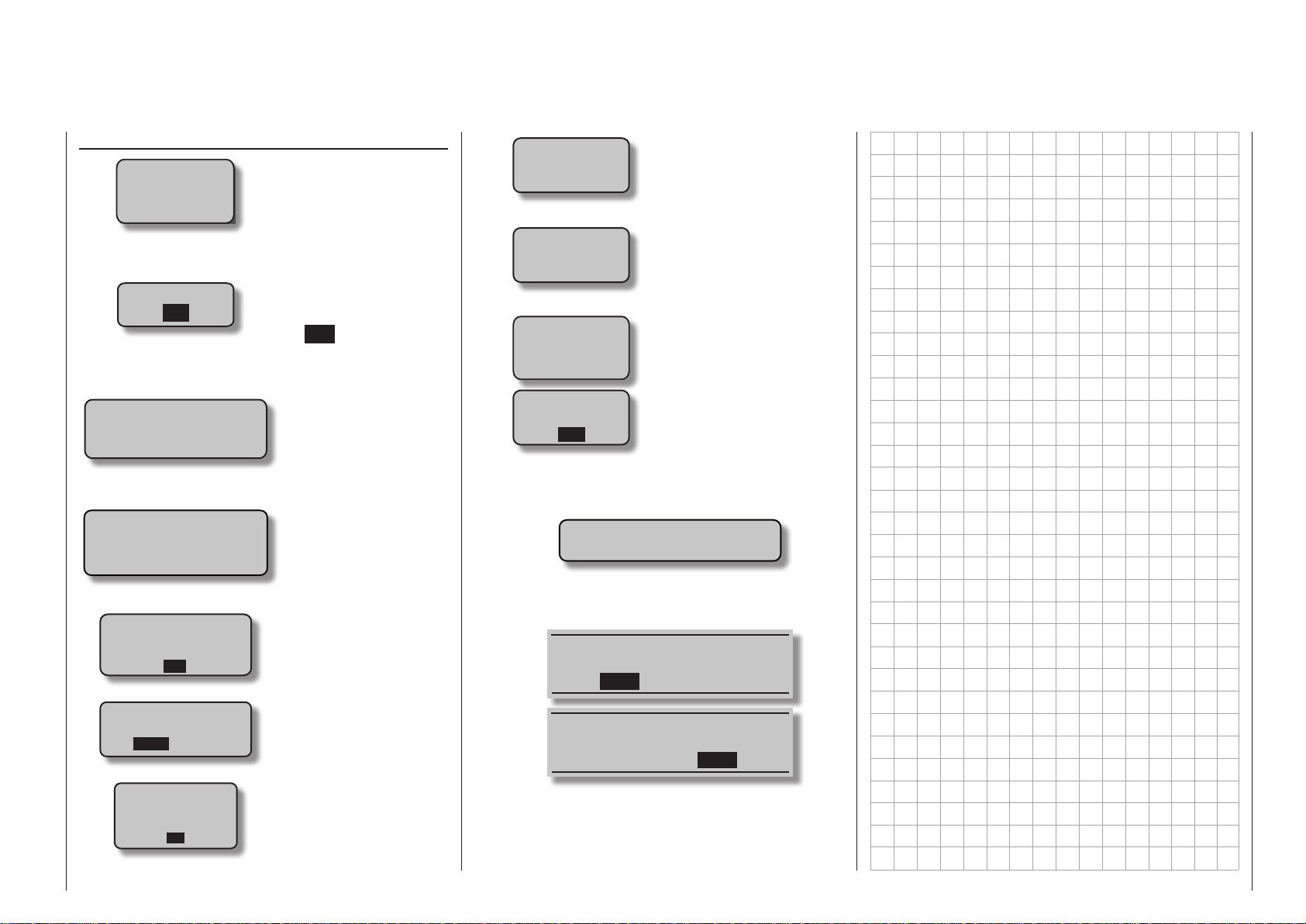
Warning notices
Warning notices
Batt. must
be re charged!!
BIND. N/A
OK
Power on warning
is active!
Attention!
Switch-OFF
the Receiver first!
CAN‘T
RECEIVE
DATA
OK
Please select
RF on/off?
ON OFF
RF
must be
OFF
OK
Operating voltage is
too low
„Bind not available“
A receiver has not yet
been bound to the
currently active model
memory. A brief tap on
the SET key will cause
a direct jump to the appropriate option.
If no controls are operated on the transmitter,
it switches itself off automatically after about
three minutes.
This warning appears
if you try to change
models in the »Model
select« menu with the
receiver of the previously active model still
switched on.
No bound receiver in
range
Only for a receiver
that has already been
bound:
Please select RF „on“
or „off“? RF
Request to switch off
the RF section.
Fail Safe
setup
t.b.d.
Failsafe has not yet
been activated
The throttle stick of a
Thr
too
high!
fixed-wing model, or
the throttle limiter of
a helicopter, is too far
in the direction of fullthrottle.
No
pupil
signal
SD-CARD
INSERT
OK
Connection between
teacher and pupil transmitter is interrupted
No SD or SDHC memory card in the card slot
or card is not legible
• If battery voltage is too low, a model switch is
blocked for reasons of safety. An appropriate message will appear in the screen:
not possible now
voltage too low
• Is the “wireless teacher/pupil connection” that was
active when the transmitter was last used to be
continued, ACT or switched off INH?
Please select
Trainer link?
ACT INH
Please select
Trainer link?
ACT INH
33Transmitter description - Warning notices
Page 34
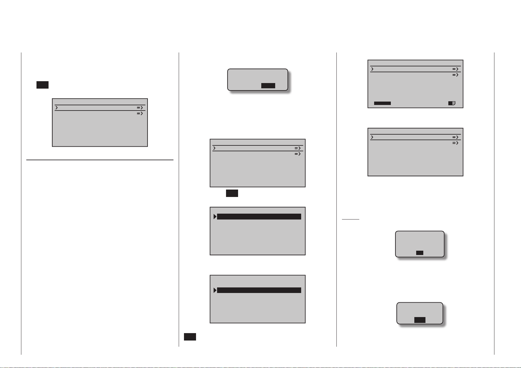
HIDDEN MODE
Language selection, Firmware update, Stick calibration etc.
The mc-16 HoTT and m c- 20 HoTT transmit-
ter’s »HIDDEN MODE« menu can be called up from
almost any menu position by touching and holding
the selection keys of the left four-way button and
the SET key of the right four-way button for at least 3
seconds. This will produce the display shown below.
HIDDEN MODE
VOICE
FIRMWARE UPDATE
STICK CALI.
BLUETOOTH INIT.
VOICE
As mentioned in section “Headsets” on page 23,
the transmitter’s acoustic signals as well as those
signals and announcements associated with the »Telemetry« menu can be output by way of the headset
connector. These announcements are made in German language by default. These announcements are
summarized in a voice packet which is stored in a
transmitter-internal memory but they can be replaced
by a voice packet of a different language at any time.
At the time of this manual’s revision, the standard
SD card delivered with the set includes the following
languages:
• Dutch
• English
• French
• German
• Italian
• Spanish
The given active language packet can be swapped
out either with the PC program available as a download from the transmitter’s web page at www.graupner.de or with the SD card, as described below. If not
already done, insert the SD card or SDHC card into
the transmitter as described on page 24. Once the
Transmitter description - Hidden mode
34
memory card is inserted in the transmitter, switch the
transmitter on with RF switched off.
Please select
RF on/off?
ON OFF
Now move to the »HIDDEN MDE« menu as described earlier in this section:
Language change
Use the selection keys of the left or right four-way button to select the line “VOICE” line:
HIDDEN MODE
VOICE
FIRMWARE UPDATE
STICK CALI.
BLUETOOTH INIT.
Use the center SET key of the right four-way button to
switch to the selection page for the “VOICE” line:
FILE LIST
VOICE2_DUTCH.VDF
VOICE2_ENGLISH.VDF
VOICE2_FRANCE.VDF
VOICE2_GERMAN.VDF
VOICE2_ITALIANO.VDF
VOICE2_SPAIN.VDF
Now use the keys of the left or right four-way button to choose the desired language, for example:
FILE LIST
VOICE2 DUTCH.VDF
VOICE2_ENGLISH.VDF
VOICE2_FRANCE.VDF
VOICE2_GERMAN.VDF
VOICE2_ITALIANO.VDF
VOICE2_SPAIN.VDF
Confirm the choice with another tap on the center
SET key of the right four-way button. The selected
language packet will be loaded into the transmitter’s
memory:
HIDDEN MODE
VOICE
FIRMWARE UPDATE
STICK CALI.
BLUETOOTH INIT.
22/100%
I
The loading process is finished as soon as the progress bar at the lower edge of the display disappears:
HIDDEN MODE
VOICE
FIRMWARE UPDATE
STICK CALI.
BLUETOOTH INIT.
When this process is finished, switch off the transmitter.
All settings stored in the transmitter remain intact
after a change of language has been made.
Notes:
• If the warning …
RF
must be
OFF
OK
… appears, then the transmitter’s RF radiation
is still active. Jump to the »Base setup mod-
el« menu, select the “RF transmit” line, select its
“OFF” option then repeat the procedure
• If the warning …
SD-CARD
INSERT
OK
… appears then the transmitter does not detect a
memory card in its card slot or the card found can-
Page 35
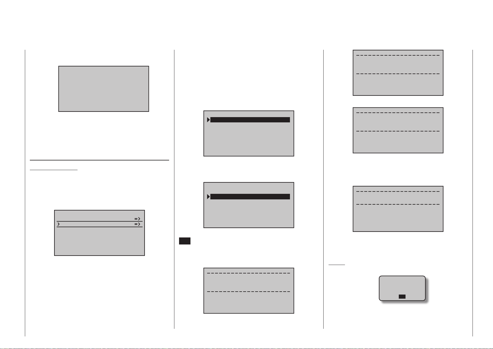
not be read.
• If the selection window is empty …
FILE LIST
… then the transmitter could not find an appropriate file on the inserted memory card. Check the
contents of the SD card’s “VoiceFile” directory on a
PC or laptop.
FIRMWARE UPDATE
Change display language
Important notice:
Be sure to check the charge status of your transmitter’s battery or charge its battery as a precaution before every update. Also backup all occupied model memories so they can be restored if
that should become necessary.
HIDDEN MODE
VOICE
FIRMWARE UPDATE
STICK CALI.
BLUETOOTH INIT.
In the same manner as described above in the section “VOICE”, this menu item can be used to update
or change the transmitter’s firmware, including its display language. At the time of this manual’s revision,
the standard SD card delivered with the set includes
the following languages:
• Dutch
• English
• French
• German
• Italian
• Spanish
Additional languages will follow at a later date.
Updates and additional information for your system
can be found on the product page for your specific
HoTT transmitter in the Download section at www.
graupner.de.
FILE LIST
MC-20_1V234_Dutch.bi
MC-20_1V234_English.
MC-20_1V234_France.b
MC-20_1V234_German.b
MC-20_1V234_Italiano
MC-20_1V234_Spain.bi
Now use the selection keys of the left or right
four-way button to choose the desired firmware version, for example:
FILE LIST
MC-20 1V234 Dutch.bi
MC-20_1V234_English.
MC-20_1V234_France.b
MC-20_1V234_German.b
MC-20_1V234_Italiano
MC-20_1V234_Spain.bi
Confirm the choice with another tap on the center
SET key of the right four-way button. The loading of
firmware into the transmitter’s memory will be started
and following two displays, visible only very briefly,
which only make reference to the firmware update …
Firmware Download
Prozess Start
Please Wait....
Boot Download
Success!!!
Please Wait....
…, the message:
Firmware
Downloading...
Progress 023/201
… will appear in the display. As soon as the counter
to the left of the “/” character reaches the value shown
on the right as the volume to be loaded, the message
…
Firmware Upgrade
success!!!
… will appear. After a few seconds this message
disappears, and the transmitter switches itself off. The
transmitter is now ready for use.
Notes:
• If the warning …
RF
must be
OFF
OK
…, then the RF section of the transmitter is still
active. Switch it off in the “RF module” line of the
»Basic settings« menu, and repeat the proce-
35Transmitter description - Hidden mode
Page 36
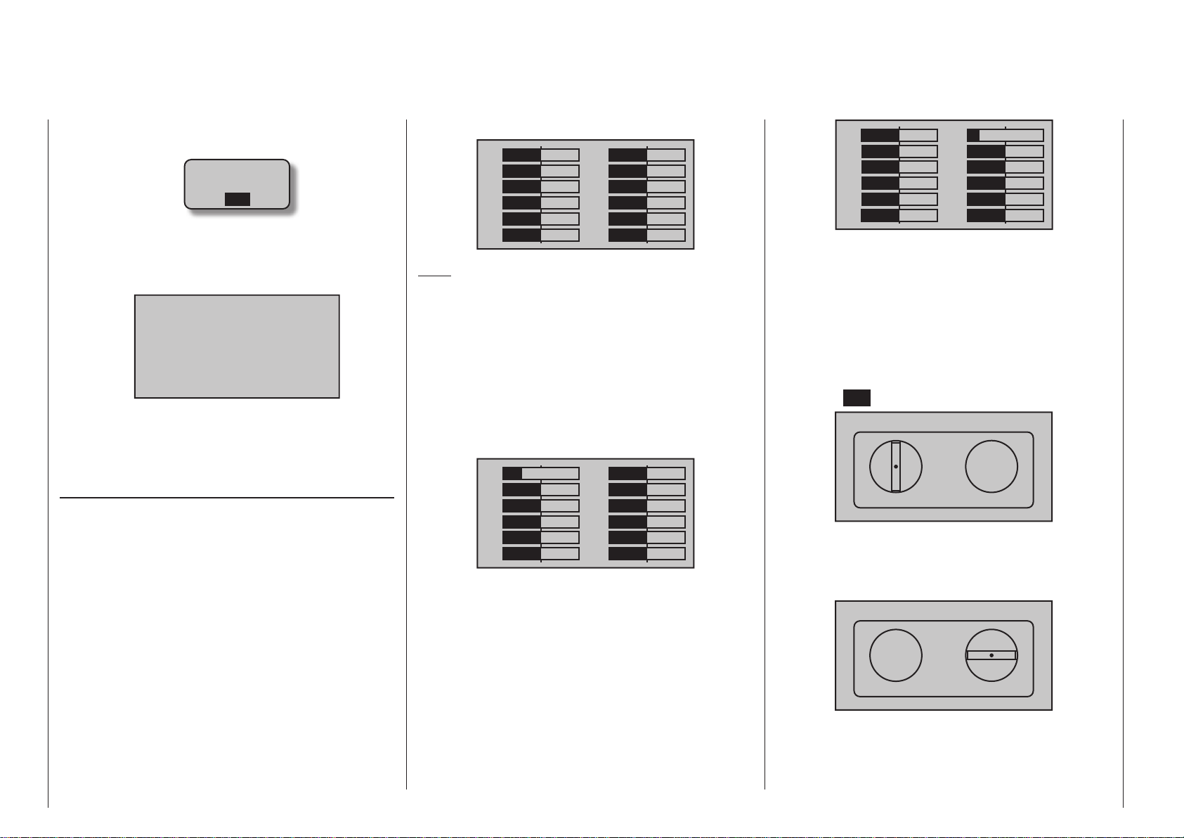
dure.
• If the warning …
SD-CARD
INSERT
OK
… appears then the transmitter does not detect a
memory card in its card slot or the card found cannot be read.
• If the selection window is empty …
FILE LIST
… then the transmitter could not find a suitable
firmware file on the inserted memory card. Check
the contents of the SD card’s “Firmware” directory
on a PC or laptop.
STICK CALIBRATION
If you feel the neutral position of your self-centering
sticks (controls 1 … 4) are not exactly 0 % of their
control travel, then this can be checked and, if necessary, corrected as follows:
Jump to the »Model select« menu and initialize a
free model memory as described on page 79.
Whether the model to be initialized is a winged aircraft or a helicopter is irrelevant.
Wait for the notices which typically appear in the
transmitter’s base screen following a model change
then jump to the »Servo display« menu, for example
by simultaneously touching the keys of the left
four-way button WITHOUT any interim changes to
trim settings or other program settings.
If all four of your transmitter’s stick functions are still
self-neutralizing, this display should ideally look like
the one shown below:
11
1
3
5
7
9
0%
0%
0%
0%
0%
0%
2
4
6
8
12
0%
0%
0%
0%
0%10
0%
Note:
The screen-shot above, and the two which follow,
show the screen of the mc- 2 0 HoTT transmitter.
The screen of the standard eight-channel mc-16
HoTT shows correspondingly fewer channels.
Otherwise the graph bars show current setting percentages for joystick control functions which are not
self-neutralizing – typically for the “C1” throttle/brake
or throttle/pitch stick. For example, if the throttle/brake
stick is in its “quarter-throttle” position, the display
would appear as shown below:
11
–50%
1
3
5
7
9
0%
0%
0%
0%
0%
2
4
6
8
12
0%
0%
0%
0%
0%10
0%
One after the other, put both sticks into each of their
four possible limit positions without exerting force at
the limit position. In each of these eight possible limit
positions, the – side dependent – indication for exactly
-100 % or +100 % should be displayed. For example,
if transmitter control 2 is at its right limit and the other
three stick functions are in their respective middle
positions then the transmitter’s display should look
like the one shown below:
11
1
3
5
7
9
0%
0%
0%
0%
0%
0%
12
2
4
6
8
–100%
0%
0%
0%
0%10
0%
Regardless of the number of self-neutralizing stick
functions available on your transmitter, if these checks
produce four 0 % results and eight 100 % results then
your transmitter’s sticks are optimally calibrated. You
can terminate this process then, if appropriate, delete
the model memory just created.
Otherwise jump (as described at the outset of the
previous double page) to the “STICK CALIBRATION”
line in the »SECRET MODE« menu then briefly touch
the center SET key of the right four-way button.
STICK CALIBRATION
0%
The selection keys of the right four-way button
will now allow you to cyclically select the four calibrated stick planes, e. g. the left/right plane of the right
stick:
STICK CALIBRATION
0%
Now position the right stick – without exerting extra
force – to its left limit corresponding with the on-screen
blinking arrow pointing to the left:
Transmitter description - Hidden mode
36
Page 37
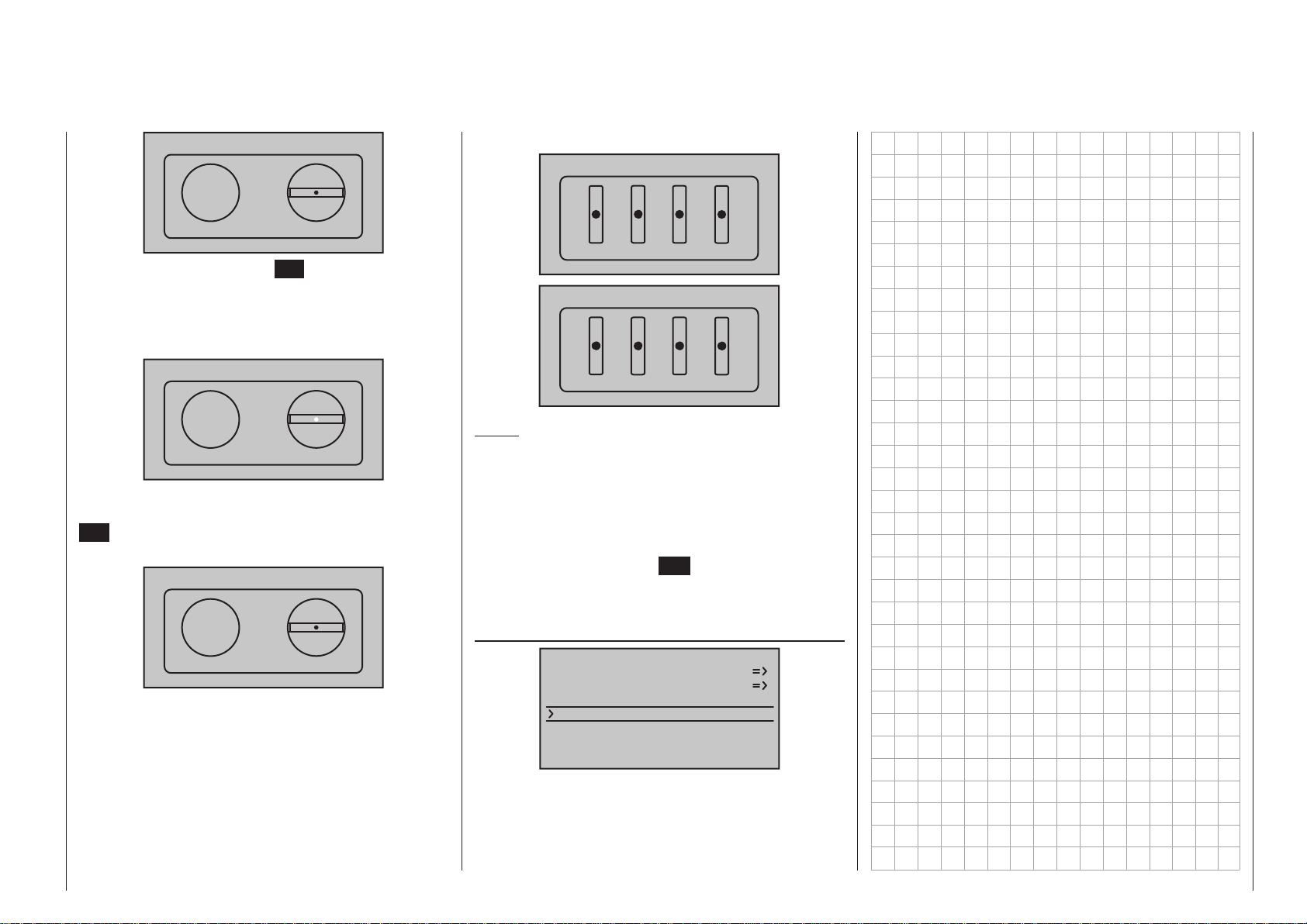
STICK CALIBRATION
+102%
… and briefly tap the center SET key of the right fourway button. This concludes this example calibration of
the right stick’s left limit. The circle in the middle of the
stylized stick plane will now blink as confirmation of
the calibration:
STICK CALIBRATION
+100%
Now release the self-neutralizing stick so it can return
to its center position and then tap again on the center
SET key to calibrate the stick’s centered position. The
right triangle marker will begin to blink:
STICK CALIBRATION
0%
Repeat the calibration process for the right limit of the
right stick. The other stick planes are calibrated analogously.
Proceed similarly to calibrate the two sliders mounted
in the middle console and the two proportional rotary
controls on the sides of the transmitter. The calibration options for these proportional controls can be
reached by repeatedly tapping on the or selection keys of the right four-way button until the desired
calibration position is reached, e. g. …
SLIDE CALIBRATION
LEVER CALIBRATION
0%
0%
Notes:
• Correct any bad calibrations by repeating the respective process.
• Within a given stick plane, each of the three calibration positions can be selected directly with the
selection keys of the left or right four-way button.
Briefly touching the center ESC key of the left fourway button will terminate the process and return to
the sub-menu “STICK CALIBRATION”.
Bluetooth initialisation
HIDDEN MODE
VOICE
FIRMWARE UPDATE
STICK CALI.
BLUETOOTH INIT.
If you install a Bluetooth module, Order No. 33002.5,
you should use this menu point to initialise it as described in the instructions supplied with the unit.
37Transmitter description - Hidden mode
Page 38
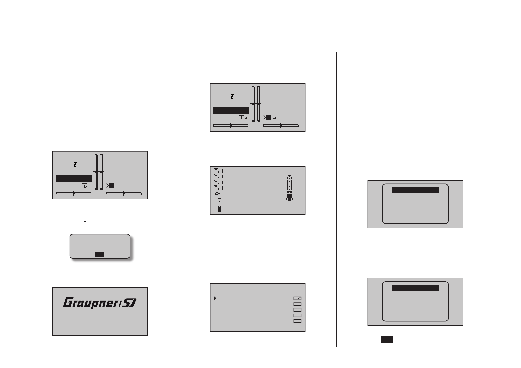
Telemetry data display
mc-16 HoTT transmitter features a single
The
screen below the aerial socket which is used both for
operating the transmitter and also to display telemetry
data in graphic form. You can switch between the two
operating modes by pressing one of the Select buttons or of the left-hand four-way button in
the base display.
mc- 2 0 HoTT transmitter has two independent
The
displays; a display for operating the transmitter and a
display just below the antenna socket for the graphic
display of telemetry data. This display is activated automatically as soon as the transmitter receives telemetry data from the receiver via the return channel.
0:00
0:00
#01
Stp
Flt
Mx
HoTT
0.0V
4.1V
0:00h
If however, at the lower edge of the base display, only
“X” – as shown in the figure above – is displayed at two
locations instead of “ ”, then the telemetry display
will show the warning …
CAN‘T
RECEIVE
DATA
OK
…, on the front screen of the mc- 2 0 HoTT, displaced shortly afterwards by the Graupner/SJ logo
and the transmitter name …
mc20
…, and this means that there is no receiver within
Transmitter description - Telemetry data display
38
range capable of exploiting the telemetry link. Switch
on the model’s receiver system or bind a receiver to
the active model memory as described in detail on
page 87 or 95.
0:00
0:00
#01
Stp
Flt
M
HoTT
4.8V
4.1V
0:01h
If a telemetry link is present, the front screen of the
mc- 2 0 HoTT shows the “Receiver” display by
default. The same occurs on the mc-16 HoTT trans-
mitter after you select the Telemetry display mode …
RX–S QUA: 100%
RX–S STR: 100%
RX–dBm: –33dBm
TX–dBm: – 33dBm
L–PACK: 10ms
RX–VOLT:4.8V TMP
R–LOW V:4.6V +22°C
… which is described in more detail in a section by
the same name on the next page.
Sensor Select
Up to four sensors can be connected, in any combination, to a telemetry-capable receiver. However, the
data output by these sensors must be (as described
on page 252) selected in the »SENSOR SELECT«
sub-menu of the »Telemetry« menu …
SENSOR SELECT
RECEIVER
GENERAL MODULE
ELECTRIC AIR.MOD
VARIO MODULE
GPS
… in order to activate their display. This data from the
selected sensors is then appropriately prepared for
illustration by the graphic indicators as described below. You must also ensure that the receiver selected
in the “Telemetry receiver” line of the »Telemetry«
menu (Bind 1 or 2) is the one to which the sensors
are connected; see pages 87 and 95. If you
select the “wrong” receiver, the “Receiver” display will
only show the data from that unit.
Furthermore, only sensors activated in the »SETTING & DATAVIEW« sub-menu of the »Telemetry«
menu, beginning page 241, according to the instructions included with the given sensor will be responsive.
To switch between the screens for activated sensors
in the »SENSOR SELECT« sub-menu of the »Tele-
metry« menu, tap briefly on one of the selection
keys of the left or right four-way button …
RECEIVER
GENERAL
ELECT. AIR
VARIO
GPS
AIR ESC
… and, after the selected screen has been displayed,
use one of the two keys to select the line of the
desired sensor. If no sensor is activated, then all display lines and sensors described in the next column,
except for the “RECEIVER” line, are blended out of
the display and the selection list:
RECEIVER
The selection can be confirmed right away by activating the center SET key of the right four-way button or
Page 39
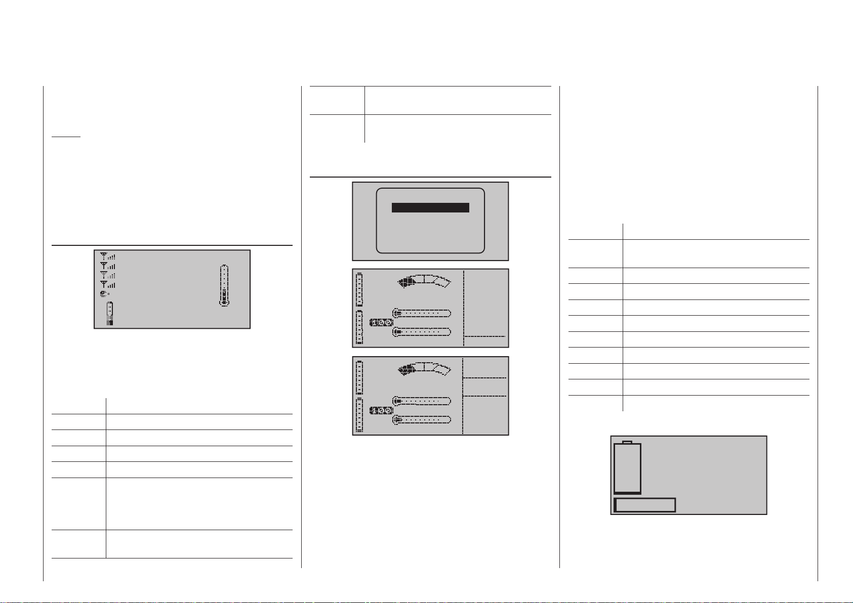
by simply waiting until, after a brief pause, the main
0ml
display of the given selected sensor appears automatically.
Notes:
• The sequence of the below described displays is
a consequence – starting from the given main display – of taps on the key.
• More details about the following named modules
can be found in the appendix and in Internet at
www.graupner.de in the web page for the given
product.
RECEIVER
RX–S QUA: 100%
RX–S STR: 100%
RX–dBm: –33dBm
TX–dBm: – 33dBm
L–PACK: 10ms
RX–VOLT:4.8V TMP
R–LOW V:4.6V +22°C
This screen presents the »RX DATAVIEW« of the
»Telemetry« menu’s »SETTING & DATAVIEW«
sub-menu, see page 241, with data processed and
displayed graphically.
The displayed items are as follows:
Value Explanation
RX-S QUA signal quality in %
RX-S STR signal strength in %
RX-dBm Reception power in dBm
TX-dBm transmit power in dBm
L-PACK Indicates the longest time span in ms
in which data packages are lost in the
transmission from the transmitter to the
receiver.
RX-VOLT current operating voltage of the
receiver's power supply in volts
R-LOW V Lowest receiver operating voltage since
last startup, in volts
TMP the thermometer depicts the receiver's
current operating temperature
GENERAL MODUL
RECEIVER
GENERAL
ELECT. AIR
VARIO
GPS
AIR ESC
BAT1
BAT2
BAT1
BAT2
E FUEL F
0.0V
T1 0°C
0.0V T2 0°C
E FUEL F
0.0V
T1 0°C
0.0V T2 0°C
CELL.V
1:0.00
2:0.00
3:0.00
4:0.00
5:0.00
6:0.00
0
ALT
0m
0m1
0m3
POWER
0.0V
0.0A
0
If attached to the receiver, this screen will display the
data acquired by a General-Engine module, order
no. 33610, or a General-Air module, order no. 33611.
More details about these modules can be found in
the appendix or in Internet at www.graupner.de in the
web page for the given product.
Depending on how this module is equipped with sensors, this screen can permanently display the data
shown in the table below.
The current voltage of up to two batteries (BAT1 and
BAT2), the measurement results of up to two temperature sensors (T1 and T2) and a fill level gage for
the fuel tank.
An alternating display along the screen’s right edge
will display a list of current cell voltages for a LiPo
battery with up to six cells or operational data (current
altitude with respect to the starting location, ascent/
decent m/1 s and m/3 s, current current being drawn
in amperes and current voltage of the battery connected to the sensor).
The displayed items are as follows:
Value Explanation
BAT1 /
battery 1 or 2
BAT2
FUEL fuel level / tank gage
E / F empty / full
T1 / T2 temperature of sensor 1 or 2
CELL V cell voltage of cells 1 … max. 6
ALT current altitude
0m1 m/1 s ascent/decent rate
0m3 m/3 s ascent/decent rate
A current draw in amperes
V battery voltage
Battery and load indicators
0.0V
0.0A
0mAh
This display depicts current voltage, current current draw and, if attached, the expended capacity
of “Batt 1” connected to the General-Engine module
(order no. 33610) or General-Air (order no. 33611)
39Transmitter description - Telemetry data display
Page 40
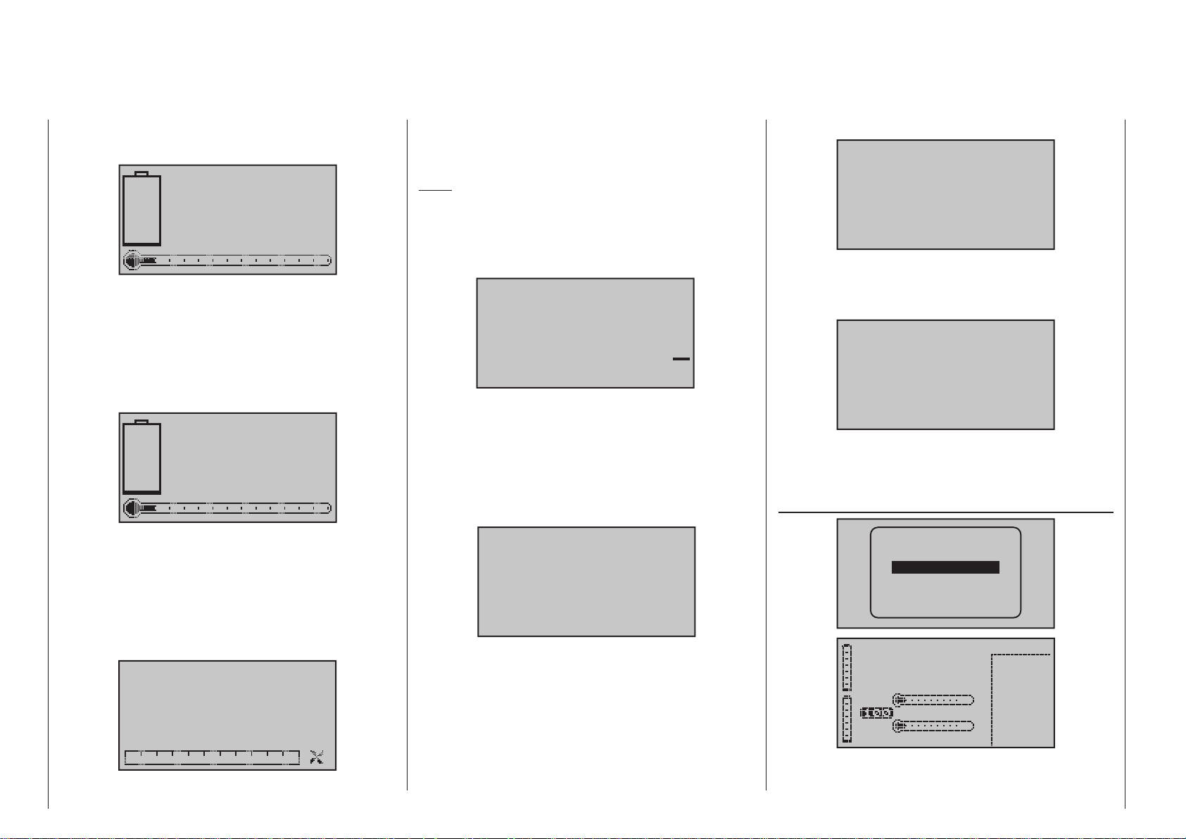
module as well as the fuel consumed in ml.
0
0.0
0
SENSOR 1
tary speed of a speed sensor (order no. 33615 or
33616) attached to a General-Engine module (order
no. 33610) or a General-Air module (order no. 33611).
Air pressure display
SENSOR 1
0.0V
0°C
If attached, this display depicts currently measured
voltage and temperature from a temperature/voltage sensor, order no. 33612 or 33613, connected
to “T(EMP)1” of the General-Engine module (order no. 33610) or the General-Air module (order
no. 33611).
SENSOR 2
SENSOR 2
0.0V
0°C
If attached, this display depicts currently measured
voltage and temperature from a temperature/voltage sensor, order no. 33612 or 33613, connected
to “T(EMP)2” of the General-Engine module (order
no. 33610) or the General-Air module (order no.
33611).
Note:
The appropriate blade count must first be set in the
module’s telemetry menu before the correct speed
can be displayed.
Vario
m
m
s
If attached, this display will depict the altitude (in m)
relative to location, starting location as well as the
current rate of ascent/descent (in m/s) data originating from a Vario integrated into a General-Engine
module (order no. 33610) or General-Air module
(order no. 33611).
Speed display
0
km/h
0.0
If the corresponding sensor is available, this screen
displays the actual air pressure.
“Weakest cell”
Bar
Cell0=0.00V
If the corresponding sensor is available, this screen
displays the voltage of the weakest cell in a battery
block, together with the number of that cell.
ELECTRIC AIR MODUL
RECEIVER
GENERAL
ELECT. AIR
VARIO
GPS
AIR ESC
Rotary speed sensor
rpm
0
If attached, this display depicts the measured ro-
Transmitter description - Telemetry data display
40
0
If the corresponding sensor is available, this screen
displays the model’s actual speed over the ground.
0.0V 0A
ALT 0m
BAT1 0m/1s
0.0V 0m/3s
T1 0°C
BAT2
0.0V T2 0°C
0
1L0.00
2L0.00
3L0.00
4L0.00
5L0.00
6L0.00
7L0.00
Page 41
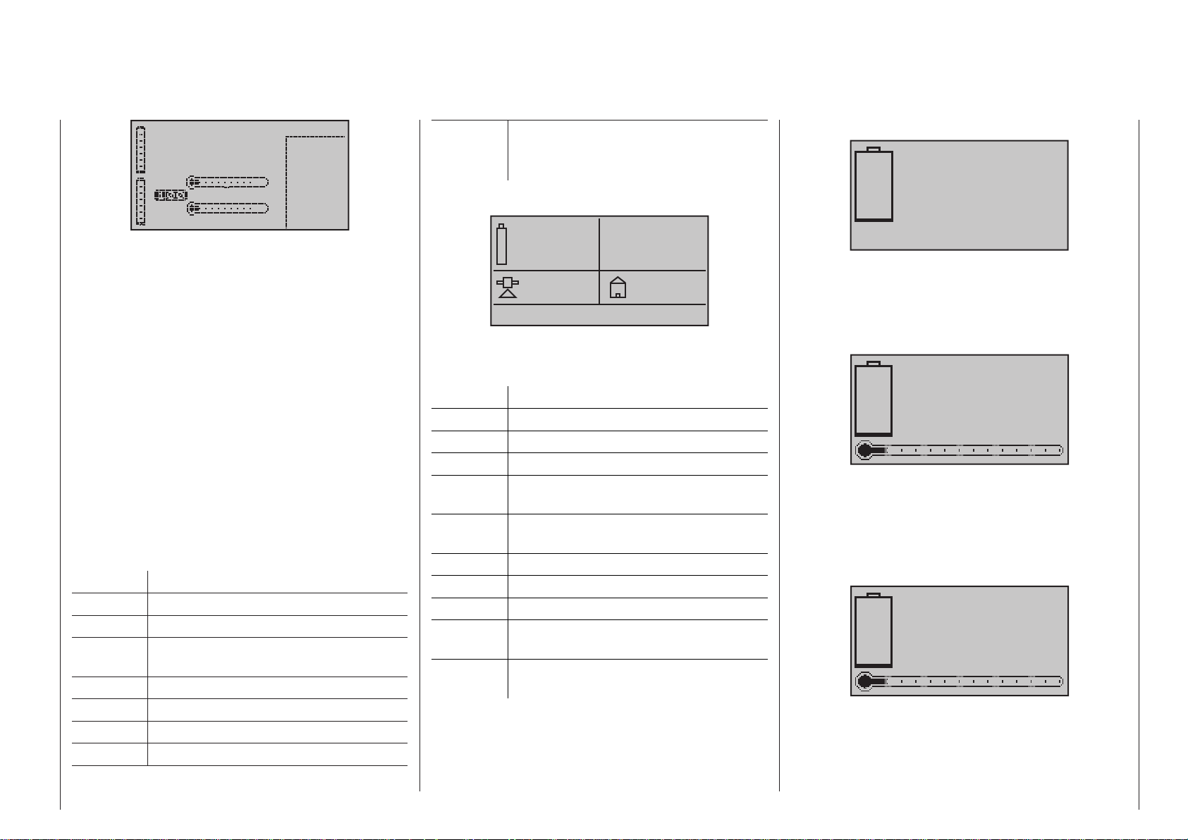
0.0V 0A
ALT 0m
BAT1 0m/1s
0.0V 0m/3s
BAT2
0.0V T2 0°C
If attached to the receiver, this display will depict the
data acquired by an Electric-Air module, order no.
33620. More details about this module can be found
in the appendix or in Internet at www.graupner.de in
the web page for the given product.
Depending on how this module is equipped with sensors, this screen can permanently display the data
shown in the adjacent table.
The current voltage of up to two batteries (BAT1 and
BAT2), up to two temperature measurements (T1
and T2), current altitude with respect to the starting
location, the model’s ascent/decent rate in m/1 s and
m/3 s and, in the middle of the screen, the current
draw currently being taken from a power source.
Along the right edge of the screen is a table of alternating values for cell voltages at balancer connections (L) or voltages for up to 7 attached battery cell
packs (H).
The displayed items are as follows:
Value Explanation
V current voltage
A current current
BAT1 /
BAT2
ALT current altitude
m/1s m/1 s ascent/decent rate
m/3s m/3 s ascent/decent rate
T1 / T2 temperature of sensor 1 or 2
battery 1 or 2
T1 0°C
0
1H0.00
2H0.00
3H0.00
4H0.00
5H0.00
6H0.00
7H0.00
L or H cell voltage of cells 1 … max. 14
L = balancer connection 1
H = balancer connection 2
Micro-copter display
0.0V
0:00
0mAh
0
0km/h
This screen displays the data generated by a HoTTcompatible micro-copter. Key, reading from top left to
bottom right:
Value Explanation
V Actual voltage
„0:00“ Period switched on
mAh Battery capacity consumed
„0“ Altitude relative to take-off point,
according to GPS system
km/h Speed over ground, according to GPS
system
Alt Actual altitude
Dir Direction of movement
I Actual current
m Distance from take-off point, according
to GPS system
° Position in degrees relative to take-off
point, according to GPS system
Any messages from the micro-copter sensor are
displayed in the bottom line of the screen, which is
empty in the screen-shot shown above.
Alt: 0m
Dir:
I:
0°
0A
0m
0°
ACCU
0.0V
0.0A
0mAh
This display depicts current voltage, current current draw and, if attached, the expended capacity of
“Batt 1” connected to the Electric-Air module (order
no. 33620).
SENSOR 1
SENSOR 1
0.0V
0°C
If attached, this display depicts currently measured
voltage and temperature from a temperature/voltage sensor (order no. 33612 or 33613) connected
to “T(EMP)1” of the Electric-Air module (order
no. 33620).
SENSOR 2
SENSOR 2
0.0V
0°C
If attached, this display depicts currently measured
voltage and temperature from a temperature/voltage sensor (order no. 33612 or 33613) connected
to “T(EMP)2” of the Electric-Air module (order
no. 33620).
41Transmitter description - Telemetry data display
Page 42

Vario
0.0
0
VARIO
Micro-copter display
m
m
s
If attached, this display will depict the altitude (in m)
relative to location, starting location as well as the
current rate of ascent/descent (in m/s) data originating from a Vario integrated into a Electric-Air module
(order no. 33620).
Speed display
0
km/h
If the corresponding sensor is available, this screen
displays the model’s actual speed over the ground.
“Weakest cell”
Cell0=0.00V
If the corresponding sensor is available, this screen
displays the voltage of the weakest cell in a battery
block, together with the number of that cell.
RECEIVER
GENERAL
ELECT. AIR
VARIO
GPS
AIR ESC
m/1s
0.0
m/3s
0.0
m/10s
0.0
If attached to the receiver, this display will depict the
data acquired by a Vario module, order no. 33601.
The displayed items are as follows:
Value Explanation
ALT current altitude
RXSQ Signal quality of the signal received by
the receiver in %, see page 241.
MAX the preset maximum altitude limit
relative to starting location at which,
when exceeded, will cause an audible
warning to be sounded
MIN the preset minimum altitude limit
relative to the starting location at which,
when underrun, will cause an audible
warning to be sounded
m/1s m/1 s ascent/decent rate
m/3s m/3 s ascent/decent rate
m/10s m/10 s ascent/decent rate
H
ALT
0
L
RXSQ
0
MAX
0m
MIN
0m
0.0V
0:00
0mAh
0
0km/h
This screen displays the data generated by a HoTTcompatible micro-copter. Key, reading from top left to
bottom right:
Value Explanation
V Actual voltage
„0:00“ Period switched on
mAh Battery capacity consumed
„0“ Altitude relative to take-off point,
according to GPS system
km/h Speed over ground, according to GPS
system
Alt Actual altitude
Dir Direction of movement
I Actual current
m Distance from take-off point, according
to GPS system
° Position in degrees relative to take-off
point, according to GPS system
Any messages from the micro-copter sensor are
displayed in the bottom line of the screen, which is
empty in the screen-shot shown above.
Alt: 0m
Dir:
I:
0°
0A
0m
0°
Transmitter description - Telemetry data display
42
Page 43
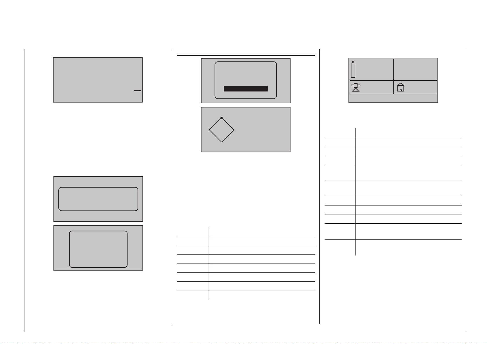
Vario
0.0
0
GPS
Micro-copter display
m
m
s
If attached, this display will depict altitude relative to
location or starting location (in m) as well as the current rate of ascent/decent (in m/s) from data acquired
by a Vario module (order no. 33601).
Text display
If the corresponding sensors are available, text from
them showing 2 x 10 or 3 x 7 characters can be
superimposed in the two following displays when
required:
RECEIVER
GENERAL
ELECT. AIR
VARIO
GPS
AIR ESC
N
0
W
Kmh
If attached to the receiver, this display will depict the
data from a GPS module with integrated Vario, Order
No. 33600.
Aside from the model’s current position and speed,
the center section of this screen will also display
current altitude with respect to the starting location
as well as the model’s current ascent/decent rate in
m/1 s and m/3 s, current reception quality and the
model’s distance from its starting location.
The displayed items are as follows:
Value Explanation
W / N / E / S west / north / east / south
Kmh speed
RXSQ return channel signal quality
DIS distance
ALT current altitude with respect to starting
m/1s m/1 s ascent/decent rate
m/3s m/3 s ascent/decent rate
E
S
N 0°00.0000
E 0°00.0000
RXSQ 0
DIS 0m
ALT 0m
0.0m/1s
0m/3s
0.0V
0:00
0mAh
0
0km/h
This screen displays the data generated by a HoTTcompatible micro-copter. Key, reading from top left to
bottom right:
Value Explanation
V Actual voltage
„0:00“ Period switched on
mAh Battery capacity consumed
„0“ Altitude relative to take-off point,
according to GPS system
km/h Speed over ground, according to GPS
system
Alt Actual altitude
Dir Direction of movement
I Actual current
m Distance from take-off point, according
to GPS system
° Position in degrees relative to take-off
point, according to GPS system
Any messages from the micro-copter sensor are
displayed in the bottom line of the screen, which is
empty in the screen-shot shown above.
Alt: 0m
Dir:
I:
0°
0A
0m
0°
43Transmitter description - Telemetry data display
Page 44

GPS
0.0
0
N
W
If attached to the receiver, this display will depict the
data from a GPS module with integrated Vario, Order
No. 33600.
The displayed items are as follows:
Value Explanation
W / N / E / S west / north / east / south
km/h speed
DIS horizontal distance in m
m/s ascent/decent rate in m/s
ALT altitude relative to starting location in m
Vario
O
S
0.0
0
0
0
km/h
DIS
m
m/s
ALT
m
Speed display
0
km/h
If the corresponding sensor is available, this screen
displays the model’s actual speed over the ground.
AIR ESC
RECEIVER
GENERAL
ELECT. AIR
VARIO
GPS
0( 0)°C
0
AIR ESC
0.0A
0.0V/ 0.0V
0mAh
0.0A
Value Explanation
V Left-hand value: actual battery voltage
Right-hand value: actual battery voltage
in present power-on period
°C Left-hand value: actual speed controller
temperature
Value in brackets: maximum controller
temperature in present power-on period
mAh Battery capacity consumed
A Centre and bar display: actual current
Right-hand value: maximum current in
present power-on period
rpm Centre and bar display: actual rotational
speed of the motor connected to the
speed controller.
Right-hand value: maximum rotational
speed in present power-on period
RPM display
m
m
s
If attached, this display will depict the altitude (in m)
relative to location, starting location as well as the
current rate of ascent/descent (in m/s) from data
originating from the Vario integrated into the GPS-/
Vario module (order no. 33600).
Transmitter description - Telemetry data display
44
0
This screen displays the data generated by a brushless speed controller with internal telemetry, Order
No. 33718 to 33770 and 33850 (correct at time these
instructions were revised), which is connected to the
receiver.
Key, reading from top left to bottom right:
0rpm
0
0
0
rpm
This screen displays the current rotational speed of
the motor connected to the brushless speed controller.
0
Page 45

Current / consumption display
0.0A
0
0.0A
0mAh
This screen displays the actual current consumption,
the peak drain which has occurred in the present
power-on period, and the capacity drawn from the
battery connected to the brushless speed controller
within the same period.
45Transmitter description - Telemetry data display
Page 46

Commissioning the transmitter
Preliminary remarks about the mc-16 HoTT and mc-20 HoTT transmitters
Preliminary remarks
The Graupner/SJ HoTT system theoretically permits
simultaneous operation of more than 200 models.
However, because of the interspersed radio-frequency utilization permitted by certification for the 2.4 GHz
ISM band, this number is significantly lower in practical application. Nevertheless, in general more models
can be operated simultaneously in the 2.4 GHz band
than would be the case in conventional 35 or 40 MHz
frequency bands. The real limiting factor is – as often
before – still likely to be the size of available operating
space (i. e. airspace for aircraft). Alone the fact that
it is no longer necessary to coordinate transmitting
frequencies with other pilots in the vicinity (which is
sometimes quite difficult in broken landscapes, such
as on hillside slopes) represents an enormous boost
for remote control operating security.
Battery charged?
Since the transmitter is delivered with an empty (not
charged) battery, the battery must first be charged
according to the charging instructions on page 16.
Otherwise a warning tone will be sounded and an appropriate message will be blended
into the basic display if the low
voltage threshold set in the “Battery warning” line of the »General
basic settings« menu, see page
Batt. must
be re charged!!
272, is underrun.
Commissioning the transmitter
46
Transmitter startup
After being switched on, the message shown below
will appear in the transmitter’s screen for about two
seconds.
Please select
RF on/off?
ON OFF
Within this brief period there is an opportunity to
switch RF transmission off by using the or key
of the right four-way button to shift the position of the
field shown in inverse video to the right so that ON
is in standard video and OFF is presented in inverse
video:
Please select
RF on/off?
ON OFF
Now switch the RF module off by tapping on the
center SET key of the right four-way button.
The telemetry display just below the antenna socket
will then briefly show the message …
CAN‘T
RECEIVE
DATA
OK
… and in parallel to this, the transmitter’s basic display will appear similar to that shown below:
0:00
0:00
HoTT
0.0V
#01
0:00h
Stp
Flt
4.1V
Mx
The symbol combination means that the currently
active model memory has already “bounded“ with a
Graupner/SJ-HoTT receiver but there is no connection to that receiver at the moment. (In this example,
RF transmission has been switched off.)
If, however, the transmitter is switched on without
switching RF transmission off, the symbolic antenna
mast will blink. At the same time, an acoustic warning will sound until a connection is established with
the respective receiver. As soon as the connection is
established, the “X” at the base of the symbolic antenna will be replace with a field strength indicator, for
example
, and the visual and acoustic warnings
will cease.
If a telemetry connection has also been established
for the incoming signal, that is output by the receiver
in the model, then the right side of this same screen
line will display a similar indication of signal strength
for this reception of the receiver’s transmitted signal
) as well as the current voltage of the receiver’s
(>M
power supply.
On the other hand, if the symbol combination
appears in the display and the front display shows the
message “Can’t receive data” then the currently active model memory is not “bound” to any receiver at
the moment.
Under-voltage warning
If the transmitter’s voltage drops below a certain
value set in the »General basic settings« menu,
page 272, 3.60 V by default, there will be visual and
acoustic under-voltage warnings issued.
Important notices:
• The transmitter in the set is already preset, as
delivered, with default values which are correct
for operation in most European countries (except France).
If the remote control system is to be operated in France then the transmitter’s “Region”
setting MUST be changed over to “FRANCE”
mode, see page 272. IN NO CASE may the
Universal/EUROPE mode be used IN FRANCE.
• Up to eight servos can be operated with the
Page 47

GR-16 receiver supplied in the
set; this receiver is supplied already bound to
the first model memory.
Up to twelve servos can be operated with the
GR-24 receiver supplied in the
set; this receiver is supplied already bound to
the first model memory.
In order to achieve the greatest possible flexibility but still preclude unnecessary inadvertent operator errors, control channels 5 … 8 respectively 5 … 12 have not been assigned
to any controls. This means that servos connected by way of these channels will remain
in their middle positions until an operator element has been assigned. Practically all mixers
are initially inactive for this same reason. More
about this can be found on page 118 (winged
aircraft) or 122 (helicopter models).
• The fundamental procedure for initial programming of a new model memory location can be
found on page 76 and the programming examples that begin on page 282.
• When the remote control system is switched
on, being bonded or when making settings,
that the transmitter’s antenna is always far
enough away from the receiver’s antennas. If
the transmitter’s antenna is brought too close
to the receiver’s antennas this will cause receiver over-modulation and its red LED will illuminate. At the same time the return channel
will drop out and, as a consequence, the field
strength indicator in the transmitter’s screen
will be replaced by an “x” and the receiver’s
current battery voltage display will show 0.0 V.
The remote control is then in Fail-Save mode,
see page 208, i. e. servos will remain in their
current positions until a new, valid signal can
be received. In such a case, increase the distance (between the transmitter and the model
mc-16 HoTT
mc- 2 0 HoTT
containing the receiver) until the indicators are
again “normal”.
• Never switch the transmitter off whilst operating a model! If this should happen accidentally,
keep your nerve and wait until the transmitter
screen is entirely blank, i. e. until the transmitter has shut down completely; this takes at
least three seconds. Do not switch your transmitter on again until this has occurred. If you
neglect this, there is a risk that the transmitter
will “hang” immediately after being switched
on, and you will lose control of the model. In
this case your only recourse is to switch the
transmitter off again, allow it to shut down
completely, and then switch on once more after the correct interval.
47Commissioning the transmitter
Page 48
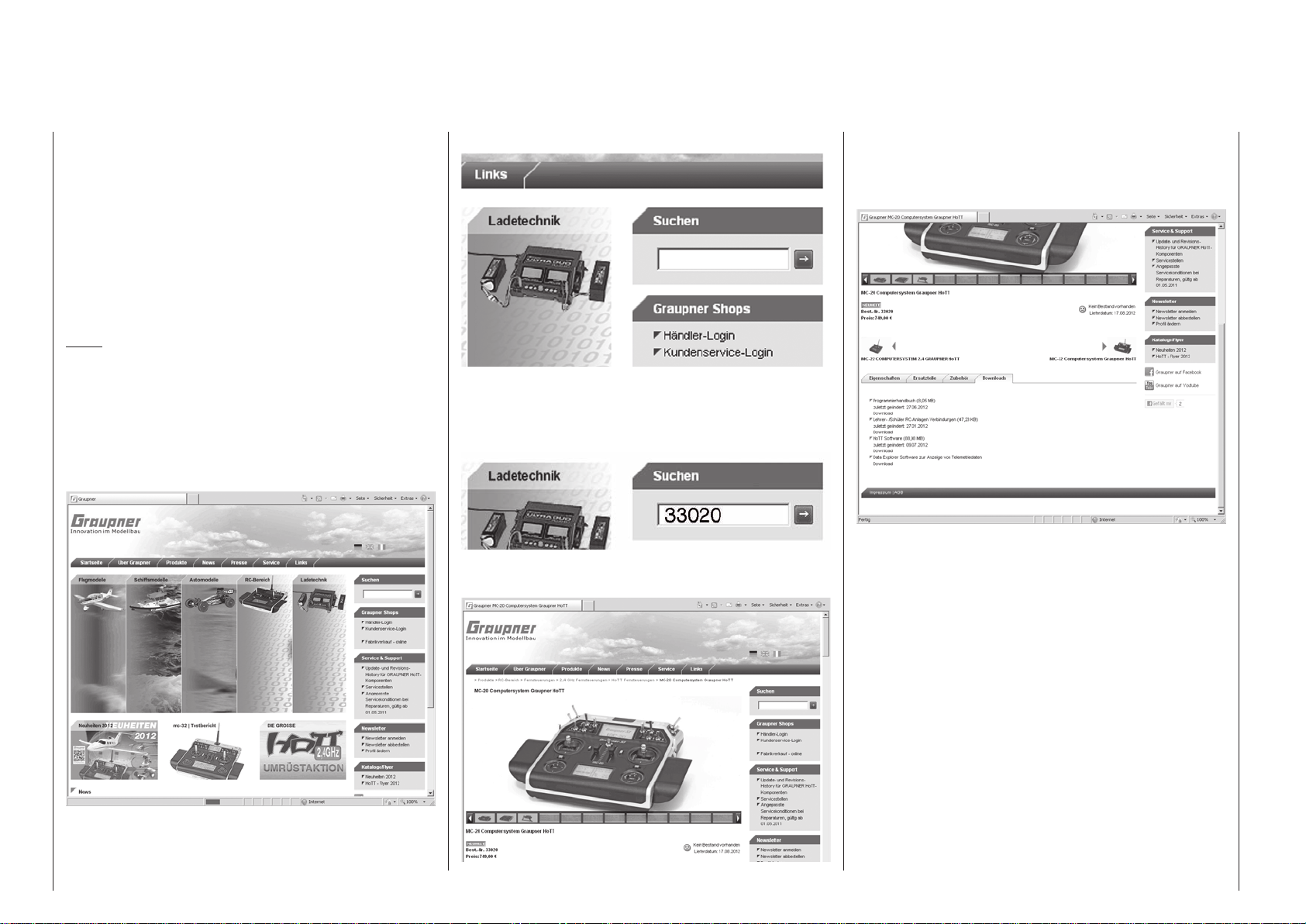
Downloading a firmware packet
Transmitter firmware updates are carried out …
• … either as described under “FIRMWARE UPDATE / Change display language” in the section
»Secret mode« on page 35 …
• … or as described below with the help of a PC
running a Windows XP, Vista or 7 operating system.
Current software and information is available in Internet at www.graupner.de under the Download link for
the given product.
Note:
You will automatically be notified of new updates per
email after registering your transmitter at https://www.
graupner.de/en/service/product_registration.aspx.
The aforementioned “given product page” is most
easily reached by entering “www.graupner.de” into
your Internet browser’s address line then pressing the
ENTER key on your PC or laptop keyboard.
On the so-called “homepage” for Graupner, click on
one of the “flags” to switch the website to a language
of your choice, e. g. the British flag for English. After-
Downloading a firmware packet
48
wards locate the entry field with the title “Search”:
Place the cursor in this field with a mouse click then
enter a search keyword, e. g. the article number printed on the type plate located on the rear side of the
transmitter:
Another press of the ENTER key on the PC or laptop
will open the sought page:
Now use your Internet browser’s vertical scroll bar
to move down the page a bit until the tabs “Characteristics”, “Spare parts”, “Accessories” and “Downloads” appear:
Move to the Download area by clicking on the “Download” tab. Select the file(s) you need, then doubleclick on “Download” below the selected file to initiate
the downloading process.
When you download “HoTT-Software VX” you actually
download the file “HoTT_Software_VX.zip”. This is
a compressed file containing all the files required to
update the transmitter, HoTT receiver, sensors etc.
Please note: at the time this manual was revised the
program packet available is Version “4”: “HoTT-Software V4”.
If you have previously updated the software of certain
components of your radio control system using the
firmware from software packet Version “V3” or earlier,
but since then have updated at least one of your components using firmware from software packet “V4”,
then it is ESSENTIAL to update all the components
of the radio control system with firmware from packet
Page 49

Version “V4”. If you neglect this, individual components could malfunction. The same applies to future
software packets, i. e. “V5” or higher.
In contrast, if changes are made to individual firmware files within a particular version “VX”, then it is
sufficient to install just the later firmware version for
the corresponding product. The easy way to check
whether firmware updates are available is to look at
the creation date of the download file. The version
numbers of the associated firmware files also change.
Now save the compressed file in a folder of your
choice, and unpack it using a suitable program.
If a transmitter update fails to work as described in
the following section, please read the chapter entitled
“Restoring your transmitter firmware” on page 52.
Note:
At the time these instructions were revised, a list
of the current firmware versions can be called up
using the following link: http://www.graupner.de/en/
supportdetail/4d589f17-24b4-4e50-97d2-13a0f39bd13d.
If the link does not work, you can obtain the same
information step-by-step via www.graupner.de =>
Service & Support => Update and revision history for
Graupner|SJ HoTT components.
49Downloading a firmware packet
Page 50
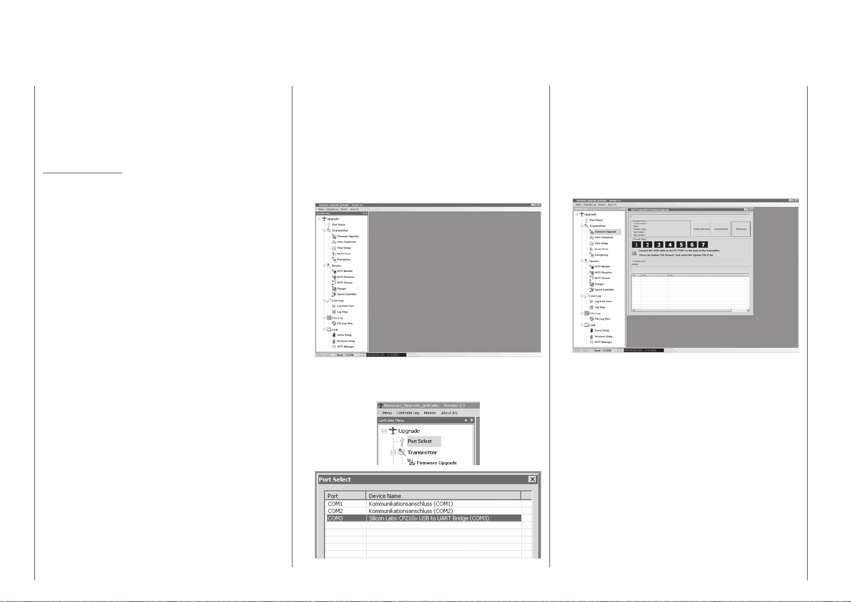
Transmitter firmware updates
The USB interface cable (USB-A to mini-B-USB
5-pole) included with the set, will be needed to update
the transmitter’s software via the transmitter’s faceside USB interface connector. This cable’s connector
is to be directly plugged into the 5-pole mini-USB
connector socket on the rear side of the transmitter.
Important notes:
• Please note that the HoTT components in your
radio control system can only communicate
perfectly if the firmware is compatible. That is
why all the programs and files required to update all HoTT components are grouped together in one file, the current version of which is
entitled “HoTT_Software_V4.zip”.
• Be sure to check the charge status of your
transmitter’s battery or charge its battery as a
precaution before every update. Also backup
all occupied model memories so they can be
restored if that should become necessary.
• It is essential not to disconnect the transmitter from the PC or laptop during an update process! Please ensure that the lead between the
transmitter and the computer is making good
contact at both ends.
1. Installing drivers
Install the required driver software, included in the
“USB Drivers” folder of the program packet, onto
your PC or laptop so your computer can handle
the transmitter’s integrated USB interface.
Start driver installation with a double-click on the
respective file and follow the on-screen instructions. Once this software has been successfully installed, the computer must be re-started. Drivers
only need to be installed once.
2. Installing the software up-loader
Unpack the file “Firmware_Upgrade_grStudio_
Ver-XX.zip” in a suitable directory then execute the
“Firmware_Upgrade_grStudio_Ver-XX.exe” pro-
Transmitter firmware updates
50
gram file with a double-click on its filename. Follow
the instructions provided by the installation wizard.
3. Establishing a transmitter-to-PC connection
With the transmitter switched off, connect the
USB cable by way of its 5-pole mini-USB socket to
the face-side of the transmitter.
4. Updating transmitter software
Start the “Firmware_Upgrade_grStudio_Ver-X.X”
program from the directory where it is located.
Use the selection sequence “Menu”, “Port Setup”
or open the “Controller Menu” and click on “Port
select”.
Now in the “Port select” window, select the COM
port connected to the USB interface. The correct
port can be recognized by its designation “Silicon
Labs CP210x USB to UART Bridge” in the “Device
Name” column. In the above example this would
be the “COM 3” port.
Now call up menu option “Firmware Upgrade” from
“Menu” or open the “Controller Menu” and click on
“Firmware Upgrade”.
Click on the button labeled “File Browse” and select the desired firmware update file with a “.bin”
filename extension from the “Open file” window.
Firmware files are product-specifically coded, i. e.
if you should accidentally select a file which does
not correspond to the product (e. g. receiver update file instead of a transmitter update file), the
“Product code error” popup window will appear
and the block the update process from starting.
Now switch on the transmitter then start the transmitter update by clicking on the “Download Start”
button.
After a brief period a warning will appear stating
that the transmitter’s RF transmission will now be
interrupted and that, because of this, any receiver
system currently in operation should be switched
off.
Page 51

Switch off your receiver system if it is switched on
then click on “Yes”.
This will start the actual update process. A progress bar will begin to operate above a sequence
of running text lines.
The connection to the PC must not be interrupted during the update process!
Click on “OK”. Subsequently switch off the transmitter and disconnect the USB cable between the
transmitter and the PC or Laptop.
If the progress bar hangs up without showing any
further progress, close the program and repeat
the update process. Be sure to watch for any error
messages that may appear.
Do not terminate the update process before the
progress bar has reached its right end and the
“Firmware Download Success” message appears.
51Transmitter firmware updates
Page 52
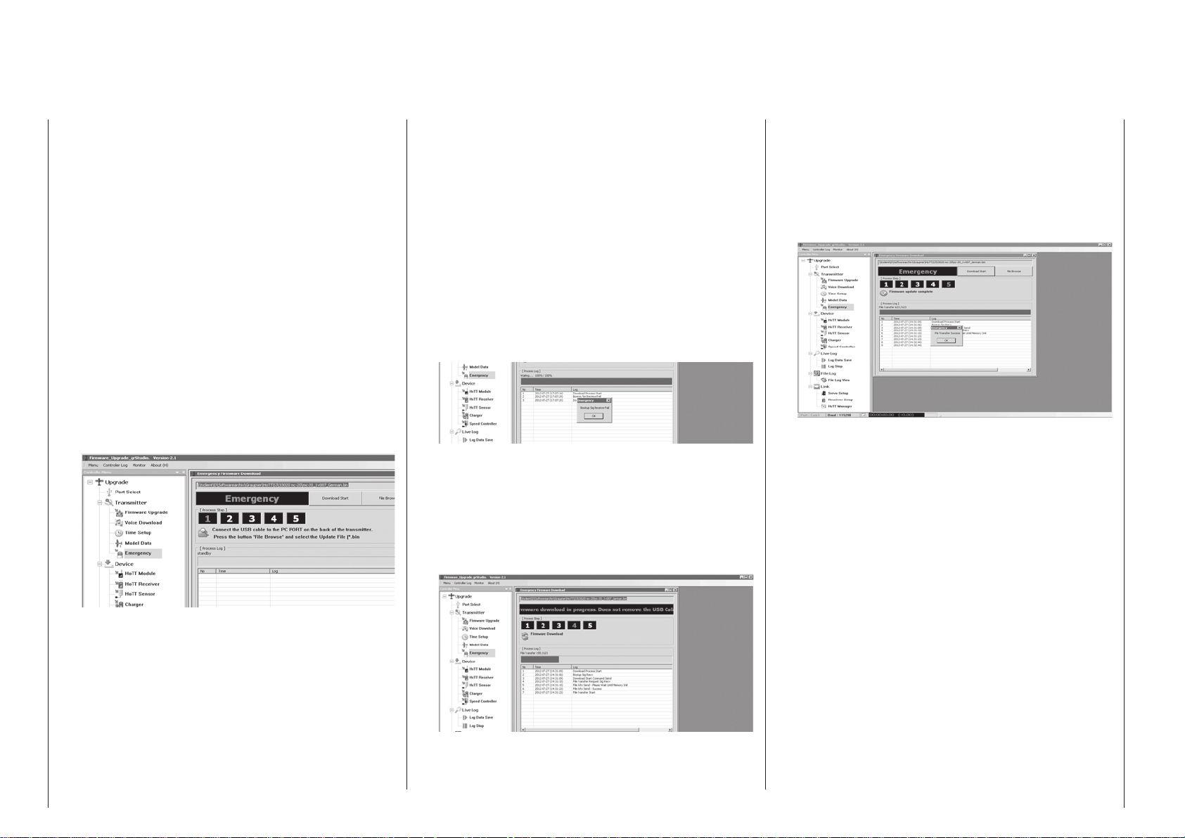
Restoring the transmitter software
Program segment: “Restore”
If a transmitter firmware update should fail, or if the
transmitter software “hangs” – it may then be impossible to switch the transmitter off using the “POWER”
switch – then you can reload the earlier firmware into
the transmitter using the “Restore” program segment.
If you find that the screen(s) are still switched on even
though you have switched the transmitter off, then
please disconnect the transmitter battery connector,
wait a few seconds, and plug it in again.
1. Preparation
Connect the transmitter to the PC or laptop, and
start the “Firmware_Upgrade_grStudio_VerX.X.exe” program as described under points 3 and
4 on page 50. (Version 2.1, which is the current
version at the time this manual was revised, starts
without being previously installed.)
2. Starting the “Restore” program segment
Now move to the “Transmitter” section and select
the “Emergency” entry under “Controller Menu”:
packed file “HoTT_Software_VX”. The file matching your particular transmitter starts with the
transmitter designation, e. g.: “mc-20_1vXXX_English.bin” or “mc-16_1vXXX_English.bin” (or “…German.bin” or …).
Now initiate the update process by pressing the
“Download Start” button. Wait for a moment until the status bar starts moving, and then switch
the transmitter on. The screen may now light up
without displaying any data, or – in the case of the
mc- 2 0 HoTT transmitter – the bottom screen
may not light up at all; don’t worry – this is quite
normal.
If the following message …
… (“Boot signal receive failed”) appears before
you switch the transmitter on, restart the update
process by clicking on “Download Start”.
The transmitter must be switched on within the
prescribed period. When you do this, it can easily take a minute for the actual update process to
start:
The update process must not be interrupted, so
please ensure that the USB lead is making good
contact at both ends.
The firmware transfer is concluded when the progress bar reaches the right-hand end. The message “Firmware update ended” indicates that the
data transfer was successful:
Now turn the transmitter on again by holding the
main switch pressed in for about one second. You
will hear the usual power-on melody, the transmitter screen(s) come to life, and you see the Start
display “mc-… HoTT” and the current firmware
version.
Finally click on “OK”. Switch the transmitter off and
disconnect the USB lead connecting the transmitter to the PC or laptop.
Note that the transmitter must be switched off!
Connect the USB lead to the PC or laptop, then
connect the other end to the USB socket under
the transmitter’s right-hand front cover.
3. Restoring the transmitter software
Press the “File Browse” button, and a program
window opens: search for the current firmware in
this window. As mentioned earlier, you will find
this in the “Official Version \33112_…_33032_mxxx_mc-32 \ SD card \ Firmware” folder in the un-
Restoring the transmitter software
52
The progress bar indicates that data are being
transferred correctly, and [Process Step] is displayed as “No 4, Firmware Update”.
Page 53

53For your notes
Page 54
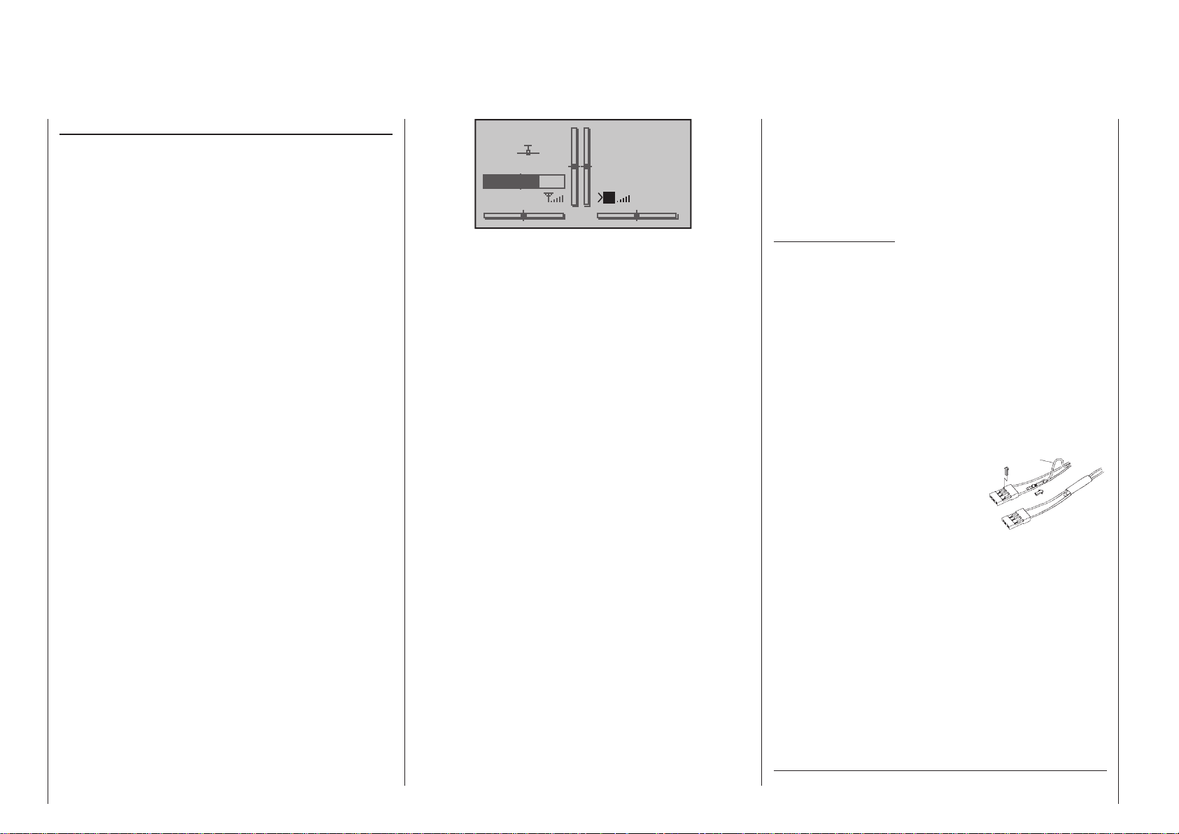
Receiver initialization
Preliminary remarks
Receiver system
The
mc-16 HoTT radio control set includes a GR-
16 bi-directional 2.4 GHz receiver, with sockets for
a maximum of eight servos. The mc-20 HoTT set
includes a GR-24 bi-directional 2.4 GHz receiver with
sockets for a maximum of twelve servos.
If you switch on the GR-16 HoTT receiver supplied in
mc-16 HoTT set, or the GR-24 HoTT receiver
the
supplied in the mc- 2 0 HoTT set, and “its” transmitter is not in range, or is switched off, then the receiver’s red LED will illuminate continuously for about 1 s
then begin to blink slowly. This indicates the receiver
has not (yet) established a link to a Graupner|SJ
HoTT transmitter. If a link has been established, the
green LED will illuminate continuously and the red
LED will extinguish.
In order to establish a link to the transmitter, the
Graupner|SJ HoTT receiver must first be “bound” to
“its” particular model memory in “its” Graupner|SJ
HoTT transmitter. This procedure is known as “binding”. This “binding” linkage is only necessary once
for each receiver/model memory combination. Refer
to pages 87 or 95. The “binding” procedure has
been done at the factory for model memory 1 of the
units delivered together as a set so this “binding” procedure will only be necessary to link additional receivers or if a memory location change becomes necessary (and – e. g. after a change of transmitter – can be
repeated anytime).
On-board voltage display
The current voltage of the receiver’s power supply will
be shown in the right side of the transmitter’s screen
if a telemetry link exists between the receiver and
transmitter:
Receiver initialization
54
Stp
#01
3.9V
2:22h
Temperature warning
Should the receiver’s temperature sink below an
adjustable threshold (default value -10 °C) or rise
above an adjustable threshold (default value +55 °C),
an acoustic warning will be issued by the transmitter
in the form of a uniform beep of about 1 s duration.
The aforementioned threshold limits are stored and
adjusted in the receiver.
Servo connections and polarity
Graupner/SJ HoTT receiver servo connections are
numbered. The connectors used are keyed against
polarity reversal. Pay attention to the small side
chamfers when plugging in these connectors. Never
use force.
The supply voltage is bussed across (i. e. common
for) all numbered connections.
The two vertical sockets at the extreme edge of the
GR-16 and GR-24 receivers are intended for the battery connection. On the GR-16 these two sockets are
marked “1+B-” and “6+B-”. On the GR-24 these two
sockets are marked “11+B-” and “12+B-”. However,
you can also connect the corresponding servos to
these two sockets in parallel with the power supply
simply by using a Y-lead, Order No. 3936.11.
Do not reverse the polarity of this connection.
Reversed polarity could destroy the receiver and
devices attached to it.
The function of every individual channel is determined
by the transmitter used, not by the receiver. It is not
only the throttle servo connection which is different for
every manufacturer and model type. For example, in
Flt
M
0:00
0:00
HoTT
5.5V
Graupner remote control systems the throttle servo is
on channel 1 for winged aircraft and on channel 6 for
helicopter models.
Follow the installation instructions on page 64 for
the receiver, the receiver antenna and for mounting
the servo.
Concluding notices:
• The significantly greater servo resolution characteristic of the HoTT system produces a noticeably
firmer response behaviour in comparison to previous technology. Please take the time to familiarize
yourself with this sensitive behaviour.
• If you have a speed controller with integrated
BEC* arranged in parallel with the receiver battery,
its positive pole (red cable) may to be removed
from the 3-pole connector. Be sure to look for notices about this in the instructions for the speed
controller used.
With a small screwdriver,
carefully lift up the connector’s center latch (1) just a bit
then pull out the red lead (2)
and tape it up with insulation
tape to prevent possible short
circuits (3).
Reset
To execute a reset of the receiver, press and hold the
SET button on the receiver’s top-side while switching
the power supply on. Hold the receiver’s SET button pressed in for about three seconds until the LED,
flashing slowly red / green, goes out for about two
seconds.
If you have carried out the reset with the transmitter
switched off, or with an unbound receiver, the green
and red LEDs fitted to the GR-16 and GR-24 receivers (supplied as standard in the sets) flash four times
for around three seconds, after which both LEDs go
* Battery Elimination Circuit
red
1
2
3
Page 55

out for just on three seconds, before only the red LED
continues to flash. Release the button as soon as the
LEDs go out.
At the transmitter and receiver it is now possible to
carry out a Binding procedure immediately.
If the reset is done on a bound receiver and the corresponding model memory is active in the powered
on transmitter, the LED will illuminate in green after
2 or 3 seconds as an indication that the transmitter/
receiver system is again ready for operation.
Please note the following:
A receiver RESET will cause ALL receiver set-
tings, except for binding information, to return to
their factory settings.
Therefore if a RESET is triggered unintentionally,
any custom settings that had been present in the
receiver before the reset will have to be established again by way of the »Telemetry« menu.
A deliberate RESET is recommended, especially
if a receiver is to be “transferred” into another
model. This is a rather simple method to eliminate
settings which are no longer applicable.
55Receiver initialization
Page 56
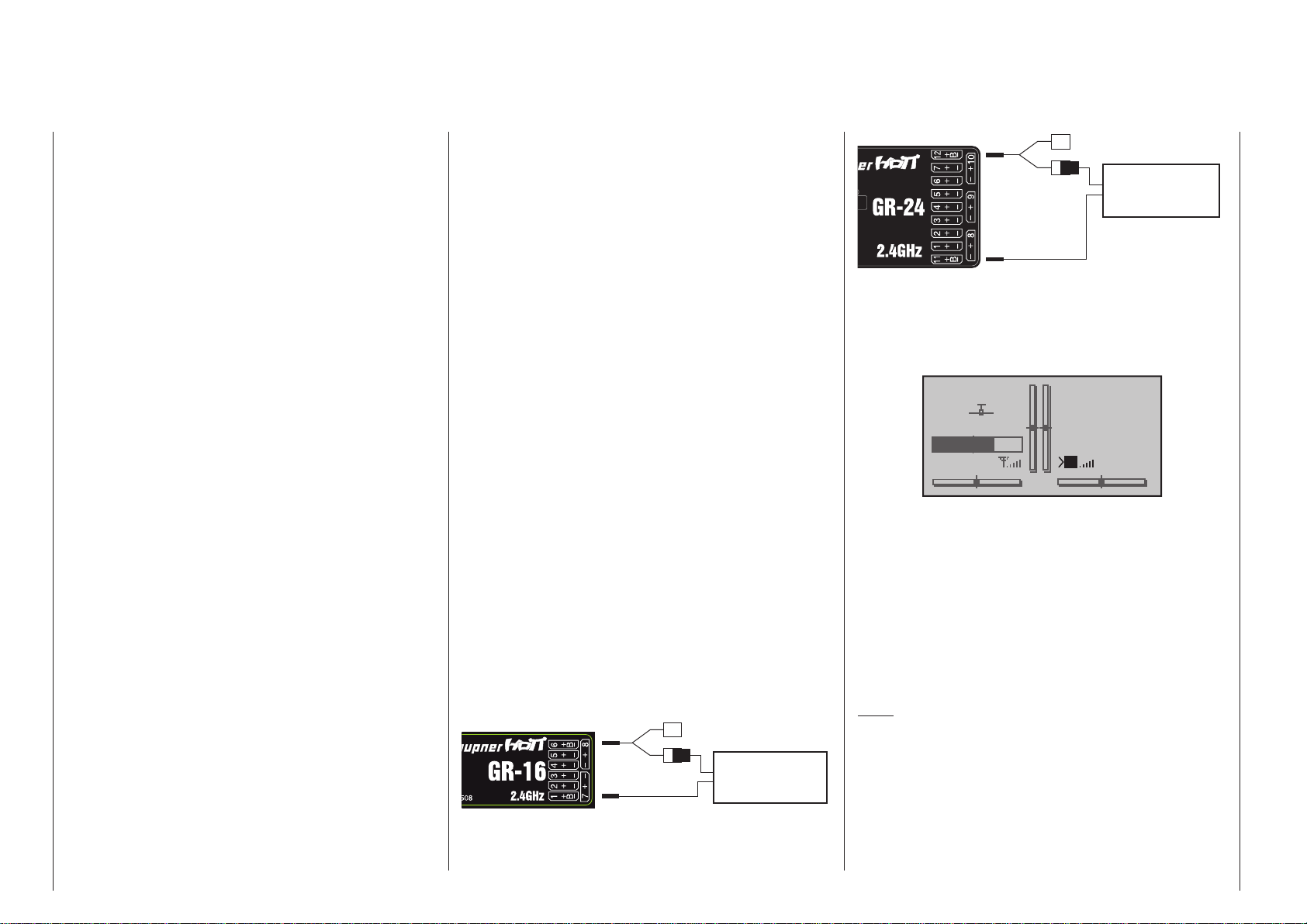
Receiver power supply
Among other aspects, the safe operation of a model
depends on a reliable power supply. In the event that,
despite smooth operating rods, fully charged battery,
battery leads with adequate cross-section, minimum
contact resistances at connectors, etc., the transmitter indicates repeated receiver voltage collapses or
is receiver voltage is generally too low; please give
attention to the following notices:
Give primary attention to fully charged batteries when
model operation is to be started. Be sure that the
contact surfaces of connectors and switches really
are low resistance. If necessary, measure the voltage
drop across installed switch cables when they are
under load because even new heavy-duty switches
can cause a voltage drop of up to 0.2 V. This value
can increase in contacts by factors as a consequence
of aging and oxidation. The constant vibrations and
jarring also takes its toll on contacts to produce a
creeping increase of contact resistance.
Servos present another possible problem source.
Even rather small servos like a Graupner/JR DS-281
can draw up to 0.75 A of current when it is blocks under load. Just four of these servos in a “foam” model
can therefore load down the on-board power supply
by as much as 3 A …
A further factor is that 2.4 GHz receivers generally
pass control signals to servos at a higher rate than
with comparable receivers used in earlier frequency
ranges. This equates to shorter “off” periods, which
also has an effect on the power consumption of the
receiving system. The current drain of many of today’s
digital servos is also higher, reflected by their greatly
improved ability to hold the prescribed position between control signals.
Therefore you should choose a power supply which
will not break down under greater loads but rather
always deliver sufficient voltage. To “calculate” necessary battery capacity you should always figure on
at least 350 mAh for every analog servo and at least
500 mAh for every digital servo.
For example, from this point of view a battery with
1400 mAh would be the absolute minimum to power
a receiver system with a total of 4 analog servos. But
be sure to also consider the receiver itself into the
calculation because its bidirectional functionality will
draw about 70 mA of current too.
Connect the power supply preferably by way of the
socket/s which are close to connectors of attached
servos. Where only high-power servos are connected,
it may be necessary to use all receiver battery connections. Even where only two batteries are used via
1 PRX it is preferable to use the receiver connections
closest to the servos which draw the most current.
The figure below shows an example of a stabilized
receiver power supply (PRX-5A, order no. 4136) for
the connection of two batteries. As an alternative
solution, a switch could be inserted with power supply cables to two receiver connectors. Such a double
connection not only reduces the risks associated with
a cable break but also ensures a more uniform supply
of power to attached servos.
If a separate battery is connected to each receiver
battery connection, be absolutely sure the batteries
have the same voltage and power rating. Never connect different battery types or batteries charged to
significantly different levels to the receiver. This can
lead to effects similar to short circuit conditions. In
such cases, insert voltage stabilizers, such as the
PRX-5A receiver power supply, between the batteries
and the receiver.
Auxiliary function
Y-lead,
Order No. 3936.11
PRX stabilised
receiver power supply,
Order No. 4136
Auxiliary function
Y-lead,
Order No. 3936.11
PRX stabilised
receiver power supply,
Order No. 4136
For reasons of safety, do not use battery boxes or dry
cell batteries.
The voltage of the on-board power supply will be displayed at the bottom right of the transmitter’s screen
while the model is in operation:
0:00
0:00
#01
Stp
Flt
M
HoTT
5.5V
3.9V
2:22h
If the voltage falls below the warning threshold – 3.80 V as standard – set in the “RX SERVO
TEST” display of the “SETUP, DISPLAYS” sub-menu
of the »Telemetry« menu, page 248, then the system generates a visual and audible low voltage warning.
Despite this feature, be sure to check the condition of the battery at regular intervals. Do not wait
for the warning to be issued before recharging
the battery.
Note:
An overview of available batteries, chargers and
current source test instruments can be found in
the Graupner RC main catalog or in Internet at
www.graupner.de. A selection of suitable Computer
chargers are listed in the table on page 16.
Receiver power supply
56
Page 57
Receiver system power supply
NiMH 4-cell battery packs
In compliance with the aforementioned conditions,
your Graupner/SJ HoTT receiver system can be readily operated with traditional 4-cell battery packs as
long as the packs have adequate capacity and voltage level.
NiMH 5-cell battery packs
Five-cell battery packs offer a greater voltage tolerance than do 4-cell packs.
However, be aware that not every servo available on
the market is able to tolerate the voltage level output
by a 5-cell pack over the long term, this is particularly
true when the battery pack is freshly charged. Some
of these servos react to this with a noticeable “grinding” sound.
Therefore pay attention to the specifications of the
servos you use before making a choice for a 5-cell
battery pack..
LiFe 6.6 V batteries with 2 cells
From a contemporary perspective, these new cells
are the very best choice.
LiFe cells are also available in hard plastic casings
to protect them from mechanical damage. Like LiPo
cells, LiFe cells can be quick charged in suitable
chargers and they are comparatively robust.
This type of secondary cell battery is also rated for
a significantly greater number of charge/discharge
cycles than, for example, LiPo batteries The nominal
6.6 V output of a 2-cell LiFe battery pack does not
present a problem for either Graupner/SJ HoTT receivers nor for those servos, speed controllers, gyros
and other devices which have been specifically approved for operation in this – higher – voltage range.
Please note however that practically all servos,
speed controllers, gyros and other devices built
in the past and most such devices currently still
offered on the market have only a permissible
voltage range of 4.8 to 6 V. Use of these batteries
in conjunction with these devices demand use of
a stabilized voltage regulator, e. g. the PRX, Order
No. 4136, see appendix. Otherwise there is danger
that attached devices will incur damage within a short
period of time.
LiPo 2-cell packs
For a given capacity, LiPo batteries are lighter than,
for example, NiMH batteries. LiPo batteries are also
available in hard plastic casings to protect them from
mechanical damage.
The comparatively high nominal voltage, 7.4 V, for
a 2-cell LiPo pack does not present a problem for
either Graupner/SJ HoTT receivers nor for those
servos, speed controllers, gyros and other devices
which have been specifically approved for operation
in this – higher – voltage range. Please note however
that practically all servos, speed controllers, gyros and other devices built in the past and most
such devices currently still offered on the market
have only a permissible voltage range of 4.8 to
6 V. Use of these batteries in conjunction with these
devices demand use of a stabilized voltage regulator,
e. g. the PRX, Order No. 4136, see appendix. Otherwise there is danger that attached devices will incur
damage within a short period of time.
Charging the receiver battery
Charger cable, order no. 3021, can be plugged directly onto the receiver’s battery for charging. If the
battery in the model is connected by way of an order
no. 3046, 3934, 3934.1 or 3934.3 power supply cable,
then charging can be accomplished via the charging
jack or special charging connector integrated into the
switch. The switch in the power supply cable must be
in its “OFF” position for charging.
Receiver battery
connection polarity
57Receiver power supply
Page 58

Receiver firmware updates
Receiver firmware updates for the GR-16 and GR-24
receivers, which are supplied as standard in the RC
sets, are carried out using the side-mounted Telemetry socket marked “- + T” and a PC or laptop running
Windows XP, Vista or 7. You will also require the USB
leads supplied in the mc-16 HoTT and m c- 20
HoTT sets, together with the USB interface, Order
No. 7168.6, and the adapter lead, Order No. 7168.6S,
both of which are also included. The programs and
files also needed can be found in Internet on the
Graupner website at www.graupner.de under the
downloads for the particular product. For more information please read the section entitled “Downloading
a firmware packet” on page 48.
Note:
After registering your receiver at https://www.graupner.de/en/service/product_registration.aspx, you will
automatically receive notification of future updates
per email.
Updating receiver firmware
Important notes:
• Please note that the HoTT components in your
radio control system can only communicate
perfectly if the firmware is compatible. That is
why all the programs and files required to update all HoTT components are grouped together in one file, the current version of which is
entitled “HoTT_Software_V4.zip”.
• Before any update procedure, be sure to check
the charged status of the receiver’s battery. If
necessary, charge the battery before beginning
with an update.
• It is essential not to disconnect the receiver from the PC or laptop during an update process! Please ensure that the lead between the
receiver and the computer is making good
contact at both ends.
1. Installing drivers
The driver software for the USB interface, Order
No. 7168.6, is identical to the driver software for
the interface installed in the
mc-16 HoTT and
mc- 2 0 HoTT transmitter. This means that the
driver only needs to be installed once; the procedure is described on page 50.
2. Establishing a receiver / PC connection
Connect the USB interface cable, order no.
7168.6, via the adapter cable, order no. 7168.6A,
with the “- + T” connector on the receiver, see illustration. These connectors are protected against
polarity reversal so pay attention to the small
chamfers on the sides of connectors. Do not use
brute force, these connectors should latch in rather easily.
Adapter lead
Order No. 7168.6S
If a central red wire is present,
cut through t
Adapter lead
Order No. 7168.6S
If a central red wire is present,
cut through it
Caution:
If the – older – adapter cable still has wires for
all three poles, cut the red insulated wire for
the middle connector pin of the adapter cable,
Order No. 7168.6A.
Afterward, connect the USB interface with the included USB cable (USB-A/mini-B-USB 5-pole interface connector) to the PC or laptop. A red LED
on the interface board should illuminate even
though the connection is made correctly.
If not already off, now switch the receiver off.
3. Firmware update
Start the “Firmware_Upgrade_grStudio_VerX.X.exe” program by double-clicking on it, exactly as described for updating the transmitter software – see page 50. (At the time of revision for
this manual, this program’s current version is 2.1
and it can be started without first being installed.)
Move to the “Upgrade” folder, open the “Controller
Menu” and click on “Port Select”. (Alternatively select the “Port Select” entry under “Menu”.)
Receiver firmware updates
58
Page 59
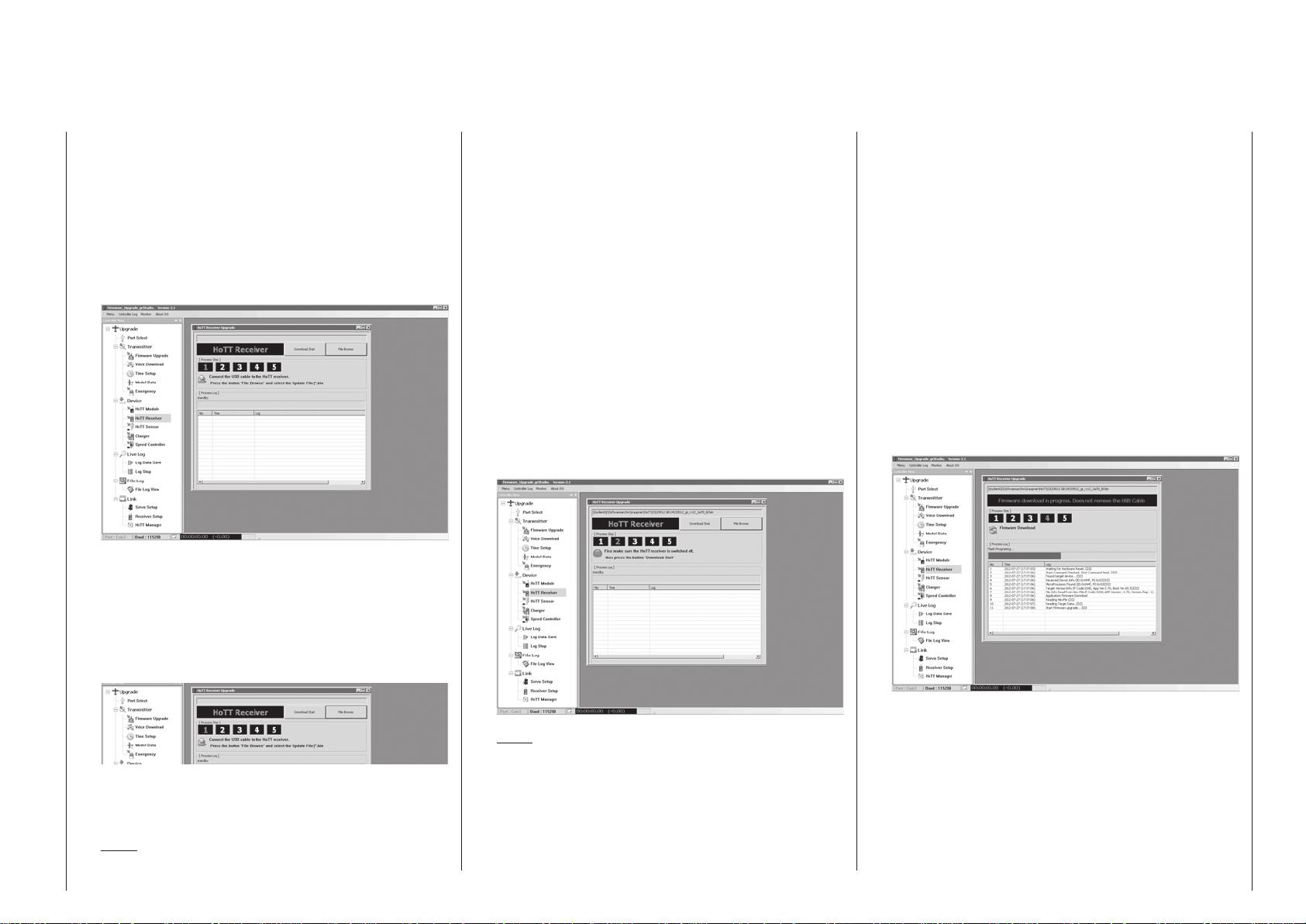
Select the correct COM port in the “Port select”
window, i. e. the port to which the USB interface is
connected. This can be identified by the label “Silicon Labs CP210x USB to UART Bridge” in the
“Device name” column. In the screen-shot shown
above this would be the “COM 3” port.
In the “Devices” folder, call up the “HoTT receiver”
option under “Controller Menu”. Alternatively select
the “HoTT Receiver Upgrade” entry under “Menu”:
When you call up the program, you will see a row
of numbers 1 … 5 in the window’s title bar; the
number “1” now flashes red to indicate that the
program is currently in “[Process Step] 1”.
The meaning of the step which is currently flashing is always displayed immediately below the row
of numbers:
at any time to call up Quick Info: this gives a brief
explanation of the individual steps:
If you have not already done so, you should now
connect your receiver to the PC or laptop. Click on
the button marked “File Browse”, and the “Open
file” dialogue opens. Select the firmware update
file matching your receiver; it will end in a “bin” suffix.
Assuming that you have already downloaded and
unpacked the zip file “HoTT_Software_VX”, the
file you need will usually be located in the folder
whose name starts with the Order Number of the
receiver you wish to update. If you are using one
of the receivers supplied as standard in the RC
sets, this would be the folder “33508_08CH_RX”
mc-16) or “33512_12CH_RX” (mc- 20). The
(
file appears in the associated window, and at the
same time the “2” starts flashing red:
With the receiver still switched off, follow the direction of “[Process Step] 2” and press the “Start update” button in the “HoTT Receiver Upgrade” window. (The announcement moves to „[Process
Step] 3“.) Wait for the progress bar to start. Depending on the speed of the computer being used,
this may take several seconds.
Now switch on the receiver while holding its SET
button down. After a few seconds the “Found target device …” message will appear in the status
display. Release the button again. The actual firmware update now starts automatically: “11, Start
Firmware upgrade …”.
However, if the receiver is not detected, the “Target device ID not found” popup window will appear.
If this should happen, check your update arrangement, and re-start the procedure:
For example, this screen-shot shows Step 1 in
progress, and the meaning is: “Connect the USB
lead to the HoTT receiver”.
Note:
You can position the mouse pointer over a number
Note:
Firmware files are product-specifically coded, i. e.
if a wrong file is accidentally selected which does
not correspond to the product (e. g. a transmitter
update file instead of a receiver update file), the
“Product code error” popup window will appear
and the update process will not start.
The progress of the firmware update is shown by
the Progress bar in the Status display.
During the update process the red and green
LEDs on the GR-16 and GR-24 receivers glow
constantly.
The connection to the PC must not be interrupted during the update process!
The update is complete when the progress bar
reaches the right-hand end. In the bottom line of
59Receiver firmware updates
Page 60

the Status display you will see “12, Complete !!”
and at the same time the [Process Steps] display
changes to “5”.
When the update process is successfully concluded, the green LED on the receiver goes out, and
the red LED starts flashing.
If this process terminates before reaching the
100 % mark, switch off your receiver’s power supply then try to start the update process all over
again. Do this by performing the above steps
again.
If you accidentally try to transfer firmware which is
older than the version stored in the receiver – even
though of the correct type – the program displays a
warning:
Click on “No” if you do not want to load an older
version of the firmware, and then load the correct
*.bin file via the “Open file” button.
After this it is ESSENTIAL to initialise the receiver, i. e. reset it to the factory default values.
ised before it is used again, and the display shown
above makes this clear. Hold the SET button on
the receiver pressed in while you switch the receiver on: if you are using a GR-16 or GR-24 receiver, as supplied as standard in the RC sets,
the green and red LEDs flash four times for about
three seconds, then both LEDs go out for three
seconds, and finally the red LED alone continues
to flash.
Release the button as soon as the LEDs go out.
Switch the transmitter on again, wait until an RF
signal is transmitted, and you will see the green
LED on the bound receiver light up continuously
for two to three seconds. If the receiver is not yet
bound, you can now carry out the binding process
with a transmitter; see pages 87 and 95.
Important note:
The receiver is now reset to the factory default values – with the exception of the binding
information – and any other settings previously
programmed in the receiver must be re-entered
if required.
If you wish to avoid this process by “rescuing”
the data, use the “Receiver Setup” program
in the “Link” segment of the program before
carrying out the update process. This will save
you the trouble of re-programming the receiver
via the “Telemetry” menu.
To do this, switch the receiver off and remove the
interface cable.
4. Receiver initialization
For safety reasons the receiver must be initial-
Receiver firmware updates
60
Page 61

61For your notes
Page 62
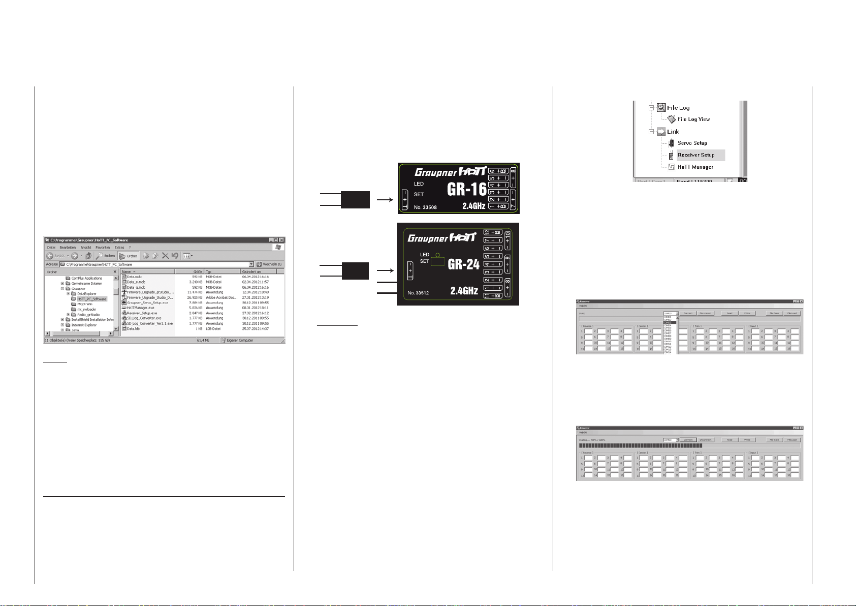
Backing up receiver settings
The “Receiver Setup” segment of the “Firmware_Upgrade_grStudio” program provides a means of backing up the data programmed in the receiver. The
data are saved in a file on your computer, so that the
same data set can be loaded back into the receiver if
required; this avoids the need to re-program the settings using the “Telemetry” menu.
It is best to call up the “Receiver Setup” application
from within the “Firmware_Upgrade_grStudio” program, but it is also possible to start it directly: you will
find the “Receiver_Setup.exe” file in the “Graupner_
PC-Software” folder.
Note:
If you call up “Receiver_Setup.exe” from the Firmware_Upgrade program via the “Receiver Setup”
menu point, you should check that the sub-program
“Receiver_Setup.exe” is located in the same folder as
the “Firmware_Upgrade_grStudio” program!
For this program you need a USB lead together with
the USB interface, Order No. 7168.6, which is supplied as standard in the radio control sets, and the
interface lead, Order No. 7168.6S.
Backing up receiver settings
1. Establishing a connection between the receiver and the PC
With the receiver switched off, connect the USB
interface, Order No. 7168.6 to the receiver socket marked “- + T” using the adapter lead, Order No.
Backing up receiver settings
62
7168.6S.
The connectors are polarised; check that the small
side chamfers are correctly aligned. On no account use force; the plugs should slide easily into
the sockets.
Adapter lead
Order No. 7168.6S
If a central red wire is present,
cut through t
Adapter lead
Order No. 7168.6S
If a central red wire is present,
cut through it
Caution:
If you wish to use the earlier adapter lead,
Order No. 7168.6A, and it is still fitted with a
three-core lead, cut through the central red
wire of the adapter lead before using it.
Connect the USB interface to the PC or laptop using the USB lead supplied (USB-A to 5-way mini-B-USB). When connected correctly, a red LED
should light up on the interface circuit board.
The receiver must remain switched off.
2. Receiver Setup: selecting the port
Start the “Firmware_Upgrade_grStudio_VerX.X.exe” program by double-clicking on it, exactly as described for updating the transmitter software – see page 50. (Version 2.1, which is the
current version at the time this manual was revised, starts without being previously installed.)
Open the “Controller Menu” and click on “Receiver
Setup” in the “Upgrade / Link” folder.
Alternatively select the “Receiver Setup entry” un-
der “Menu”:
A program window now appears: the first step is
to set the “correct” COM port for the USB interface, Order No. 7168.6. If you are not sure of this,
check the COM port in the “Port select” window of
the “Controller Menu” (see earlier), and note the
COM port number associated with the entry “Silicon Labs CP210x USB to UART Bridge”. If everything is as described earlier, this would be the
“COM 3” port.
(If you select the wrong port, the program will inform you of your error.)
3. Reading out receiver data
Click on the “Connect” button and wait until the
lower Status bar starts moving:
Hold the SET button on the receiver pressed in
while you switch it on. After about three seconds
the current values stored in the receiver are displayed in the corresponding fields. If the progress
bar is “faster than you are”, and reaches the end
before you have switched the receiver on, the popup window shown subsequent will appear.
Page 63
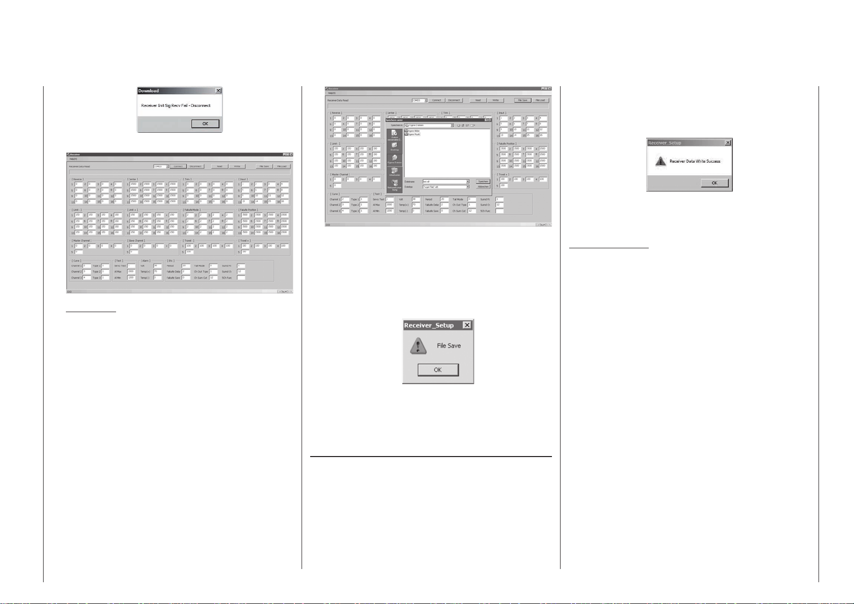
Repeat the procedure:
Important:
The active connection can be terminated using the
“Disconnect” button, but you should only do this if
you intend to initialise the receiver directly – as described on page 60 – and do not wish to overwrite the contents with a data set you backed up
earlier.
4. Saving receiver data
The “File Save” button stores the current servo
configuration on the PC.
The Windows dialogue “Save as” now opens:
First select a suitable folder in which to save the
file, and enter an unambiguous name under “File
name”, so that you can assign the file again at a
later stage. The program automatically appends
the file suffix “rdf”. The data set is saved when you
click on the “Save” button. When the process is
complete, this message appears:
Click on “OK” to close this.
Now you can reset the receiver to the factory de-
fault settings as previously mentioned and described on page 60.
Copying a data set to the receiver
The backed-up data can be reloaded using the “File
Load” function in the Receiver Setup program.
First connect the receiver as described in point 3
“Reading out receiver data”, and click on the “Connect” button. If the receiver has previously been
initialised, the software reads out the factory default
settings.
Now select the appropriate “rdf” file from the appropriate folder, and click on “OK” in the “File Load” pop-up
window. Clicking on the “Write” button transfers the
data to the receiver connected to the PC.
As soon as the transfer is complete, the pop-up window “Receiver Data Write Success” appears:
Click on “OK” to conclude the data transfer procedure,
then click on the “Disconnect” button to separate the
Receiver Setup program from the receiver.
Important notes:
• The “Receiver Setup” program includes additional functions which are still at the development stage, and must not be used at this juncture. You can check the current state of the
software in the Download area for your particular receiver.
• A separate manual dealing with the whole
“Firmware_Upgrade_grStudio_Ver-X.X” program packet is in preparation, and will be
made available in the Download area when it
is ready. The manual will then be continuously
updated whenever new options become available.
63Backing up receiver settings
Page 64

Installation notices
Receiver installation
Regardless of which Graupner receiver system you
use, the procedure is always the same.
Please pay attention that the receiver’s antennas
must be mounted at least 5 cm away from all large
metal parts or any wiring that is not directly routed
out of the receiver itself. In addition to steel parts, this
also includes carbon fiber parts, servos, fuel pumps
and all kinds of cables etc. Optimally the receiver
should be placed at a readily accessible location
that is well away from all other equipment. Under no
circumstances may servo cables be wrapped around
the antennas or routed close to it.
Please note that cables are subject to the acceleration forces which occur during flight and these forces
may cause such cables, to shift in position. Therefore
be sure the cables in the vicinity of the antennas are
not able to move. Such moving cables can cause
reception disturbances.
Tests have shown that a single receiver aerial should
be deployed in the vertical (upright) orientation for
best results during long landing approaches. If your
receiver is an aerial diversity type – two aerials – then
the active tip of the second aerial should be positioned at 90 ° to the tip of the first aerial, and ideally
the distance between the two tips should be greater
than 125 mm.
If your model features a carbon fibre fuselage, the
aerial tips must always extend outside the fuselage
for a length of at least 35 mm. If this is not possible,
it is essential to substitute longer aerials (300 mm,
Order No. 33500.2, or 450 mm, Order No. 33500.3)
for the standard ones (approx. 145 mm long) fitted to
HoTT receiver(s).
The sockets marked “X+B-” on the HoTT GR-16 and
GR-24 receivers supplied in the sets are intended for
the battery connection. The power supply is passed
through all the numbered sockets, and in principle
the battery can be connected to any of the eight (or
Installation notices
64
twelve) sockets. A Y-lead can then be used to connect
the corresponding servo.
However, please note that the transverse sockets of
the GR-12 should not be used for the connection of a
receiver battery due to additional voltage losses.
The function of every individual channel is determined
by the transmitter used, not by the receiver. However, channel assignments can be changed in the
receiver by programming done in the »Tele metry«
menu. However, it is advisable to carry this out at the
transmitter using the »Tx. output swap« option; this
is available as standard on the
mitter, but has to be unlocked (at extra cost) on the
mc- 2 0 HoTT trans-
mc-16 HoTT transmitter; see page 230.
Several notices and suggestions for installing
remote control components into a model are provided below.
1. Wrap the receiver in a foam rubber pad that is at
least 6 mm thick. Attach the foam rubber to the receiver with rubber bands so it will be protected
against vibration and/or the jars of a hard landing.
However, do not enclose your receiver completely,
otherwise it may overheat in use.
2. All switches must be installed such that they are
not affected by exhaust gases or vibration. The
switch knob must be freely accessible over its entire range of movement.
3. Mount servos on rubber bushes/spacers with hollow brass bearings to protect them from vibration. Do not tighten the fastening screws down too
tight as this would negate the vibration protection
to be provided by the rubber bush/spacer. Only
when servo fastening screws are properly tightened will this arrangement provide security and vibration protection for your servos. The figure below
shows how a servo is mounted properly. The brass
bearings are to be pushed into the rubber bushes/
spacers from below.
Servo mounting lug
Retaining screw
Rubber grommet
Tubular brass spacer
4. Servo arms must be free to move throughout their
entire range of motion. Pay attention that there are
no objects which could hinder servo arm motion.
The sequence in which servos are connected to the
receiver depends on the type of model. Follow the
connection layouts provided for this on pages 73
and 75.
Also observe the safety notices provided on pages
4 … 9.
In order to prevent uncontrolled movements of servos
connected to the receiver during startup
always first switch on the transmitter
and then the receiver
and when finished with operation
first switch off the receiver
and then the transmitter.
When programming the transmitter, be sure that electric motors cannot start running without control or that
a combustion motor equipped with automatic starting
cannot start up unintentionally. To be safe, disconnect
the receiver’s drive battery or, in the case of a combustion motor, disconnect the fuel supply.
Page 65

65For your notes
Page 66

Definitions of terms
Control function, control, function input, control channel, mixer, kind of switches
To make use of this manual easier, a number of the
terms used repeatedly throughout this manual have
been defined below.
Control function
A “control function” is to be perceived – initially independent of its signal path – as a signal intended to
affect a given control function. For example, this could
be for throttle, rudder or aileron in a winged aircraft or
pitch, roll or crow for a helicopter.
A control function signal can be applied directly over
a single control channel or also through a mixer and
then applied over multiple control channels. A typical
example of multiple control channels is separately
operated aileron servos or the use of two roll or crow
servos in helicopters. The control function explicitly includes the influence of the control’s mechanical travel
on the respective servo. This can not only be spread
or compressed by software but even the travel characteristic can be modified from linear to extremely
exponential.
Control
“Controls” include all operating elements on the transmitter, which are directly activated by the pilot, that
impose an effect on servos, speed controllers etc.
connected to the receiver. This includes:
• both sticks for control functions 1 through 4,
whereby these four functions can be freely
swapped around for both model types (“winged
aircraft” and “helicopters”) by way of software
“Mode” settings, e. g. throttle left or right. The stick
function for throttle/airbrake control at “winged
aircraft” or throttle/pitch control at “helicopters” is
often also referred to as the C1 control (channel
1).
• both proportional controls located on the transmitter’s sides, which are, for example, given the
de signations Lv1 (left-side “rotary slider”) and Lv2
(right-side “rotary slider”) in the »Control adjust«
Term definitions
66
menu, page 118 and 122.
• the two INC/DEC buttons, which are fitted on both
sides of the front screen on the
transmitter only. These are typically labelled Cn5
and 6 in the »Control adjust« menu; see sections
starting on page 118 and 122.
If they are assigned as transmitter controls in the
»Control adjust« menu, these buttons can be
used to move a servo in 1 % increments relative
to the servo travel currently set (as selected in the
»Servo adjustment« menu.) When you press one
of the INC/DEC buttons, the positions are briefly
superimposed on the base display.
They are ideal for tasks such as setting flight
phase specific flap positions and similar fine trimming. If a button is held pressed in, the rate of
change automatically speeds up – indicated by a
faster sequence of audible beeps; a different beep
indicates the centre position. Since you can opt for
the (trim) position of these two transmitter controls
to be stored separately for each flight phase – provided that they have been assigned to one of the
inputs 5 … 12 in the “Control adjust” menu – you
can use one and the same INC/DEC button in the
same way for all flight phases you may have programmed. This does not apply to position-dependent proportional transmitter controls.
• the two proportional sliders in the middle console
designated Sl1 and 2, for example as shown in the
»Control adjust« menu, page 118 and 122,
• the switches present, if they are assigned to a
control channel in the »Control adjust« menu.
The proportional operating elements produce a direct
effect on servos which is commensurate with the control’s position whereas switch modules can only effect
a two or three increment change.
Just which of these controls and switches operate
which of the servos 5 … 8 respectively 5 … 12 is
freely programmable.
mc- 2 0 HoTT
Important notice:
The transmitter is supplied with default programming in which certain inputs are “free”, i. e. not yet
assigned to any function. These inputs are: 5 … 7
(mc-16) and 5 … 11 (mc- 2 0 only as standard)
for model helicopters, and 5 … 8 (mc-16) and 5
… 12 (mc- 2 0 only as standard) for fixed-wing
model aircraft.
Function input
This is an imaginary point in the signal path and must
not be considered the same as the point on the circuit
board where the transmitter control is connected. The
choice of “Stick mode” and settings in the »Con-
trol adjust« menu have their effect “downstream” of
these imaginary connection points. Thus differences
between the physical control’s number and the number of the downstream control channel can indeed
emerge.
Control channel
From the point at which a signal contains all control
information necessary for a particular servo – whether
directly from the physical control or indirectly by way
of a mixer – the term “control channel” is used.
(For example, for a fixed-wing model aircraft set up
as the model type “2AIL”, this means that the “Aileron”
control function is divided into the control channels
left and right aileron. Similarly: for a helicopter set up
as the “3Sv(2roll)” type, the “Roll” control function is
split into the control channels left and right roll servo.)
The signal of this type of control channel can only
be further influenced by the settings entered in the
»Servo adjustment« menu (and in the »Tx. output
swap« menu, which is available in the
HoTT transmitter only, but can be unlocked in the
mc- 2 0
mc-16 HoTT transmitter); the signal then leaves the
transmitter via the RF module.
Once it arrives at the receiver, this signal may still be
modified by settings made in the »Telemetry« menu
Page 67

before finally being applied as a control quantity for
the respective servo.
ing advantage of the programming examples beginning on page 280.
Mixer
The transmitter’s software contains a variety of mixer
functions. These can be used to apply one control
function to multiple servos or, conversely, to apply
multiple control functions to a single servo. Please
look over the numerous mixer functions in the text
beginning on page 169 of this manual.
Switches
The standard toggle switches, the 3-way switches
and both push-button switches can also be incorporated into control programming. However, these
switches are generally intended for switching program
options, e. g. to start and stop timers, to switch mixers
on and off, or as a teacher/pupil switchover, etc. Each
of these switches can be assigned any number of
functions.
Appropriate examples are detailed in the manual.
Control switches
Since it is very practical to have some functions automatically switched on or off for a certain control’s
position (e. g. switch on/off of a stopwatch for acquisition of model run time, automatic extension of spoilers and other possibilities), four control switches have
been integrated into
HoTT software.
These software switches, designated “C1 … C4”, are
merely defined by virtue of their contact state along
the physical control’s course of travel by the touch of
a key. The switching action can be correlated to the
physical control’s travel direction by software.
Of course control switches can also be freely combined with the aforementioned physical switches to
solve even more complex problems.
There is a series of instructive examples which make
this programming child’s play. Learn about this by tak-
mc-16 HoTT and m c- 20
Logical switches
This function, which is available as standard on the
mc- 2 0 transmitter only, allows two switches, con-
trol switches and / or logical switches, or any combination of the above, to be linked in an “AND” or “OR”
circuit. Eight logical switches “L1 … L8” can be programmed in total; see page 148.
Fixed switches FXI and FX
This type of switch turns a function, e. g. a timer, permanently on (closed fixed switch) or off (open fixed
switch) or they can provide a fixed input signal for a
control function, e. g. FXI = +100 % and FX = -100 %.
For example, in flight phase programming, these fixed
switches can be used to switch a servo or speed
controller between two settings.
67Term definitions
Page 68
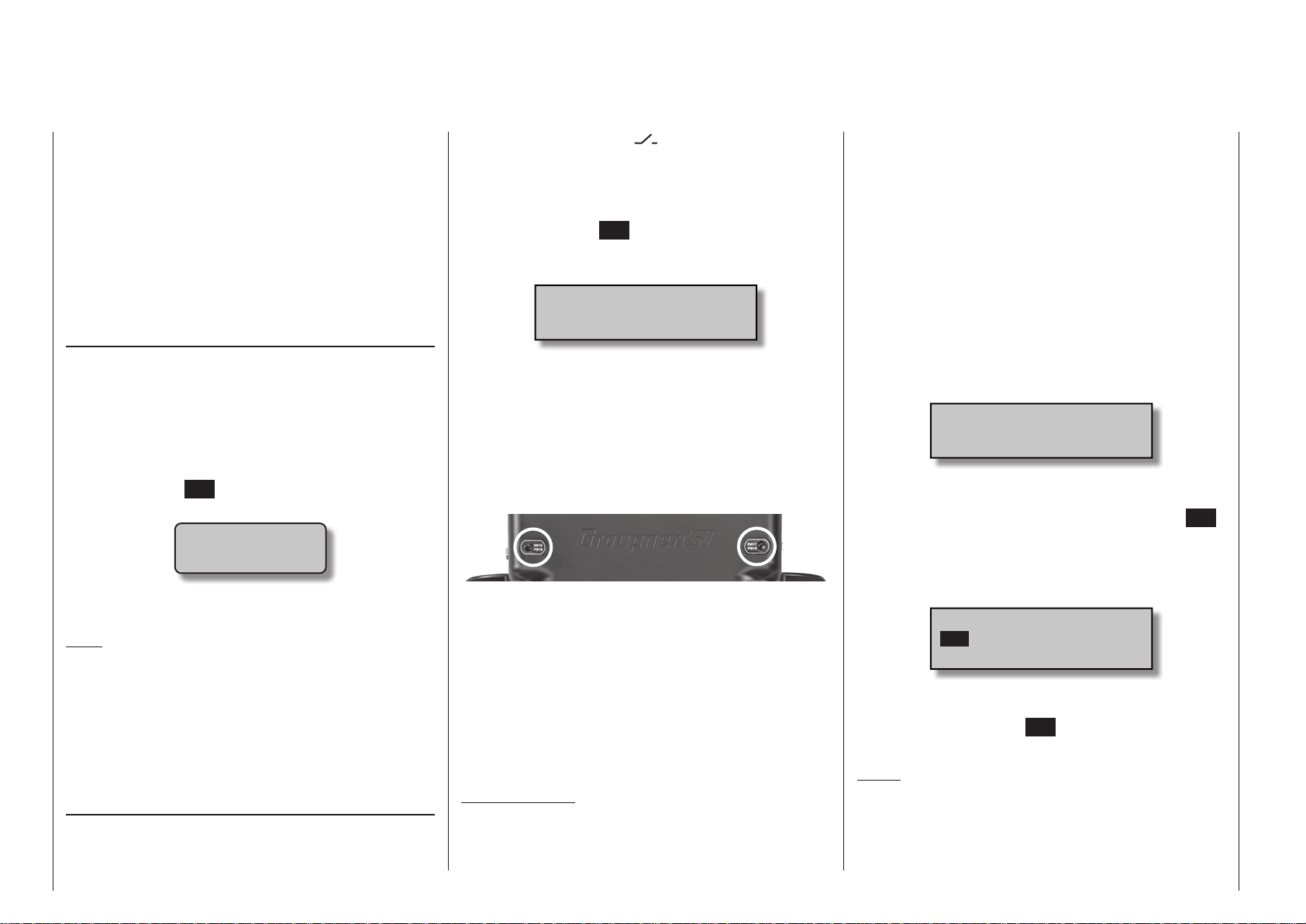
Physical control, switch and control switch assignments
Principle procedure
Maximum flexibility is offered by the mc-16 Hott and
mc- 2 0 HoTT system when it comes to assigning
standard equipment operating elements to certain
functions.
Since the assignment of controls and switches is
done in the same way, even though different menus
may be involved, it is appropriate at this point to
explain the fundamental programming technique so
that users can concentrate on the particular contents
when reading the detailed menu descriptions.
Transmitter control assignment
It is possible to assign any direction of transmitter
control (Ch1 … Ch4), and also any available transmitter control, to inputs 5 … 8 (
12 (mc- 2 0 only as standard) at the transmitter,
in order to operate servos. This is carried out in the
third column of the »Control adjust« menu; see the
sections starting on pages 118 and 122. When you
press the central SET button of the right-hand touchkey the following window appears on the screen:
Move desired
control adj.
Now simply operate the transmitter control you wish
to use.
Note:
The software only detects the transmitter control after
it has moved a certain distance: move it left or right,
or forward or back, until the assignment is displayed
on the screen. If the travel in one direction is not sufficient, move the control in the opposite direction.
The same method is used throughout the other menus when transmitter controls have to be assigned.
Switch assignment
Wherever programming permits a switch to be assigned, a switch symbol will appear in the screen’s
bottom display line:
Physical control, switch and control switch assignments
68
mc-16) and 5 …
Use the selection keys in the left or right four-way button to select the appropriate column.
How to assign a switch
1. Briefly touch the SET key of the right four-way button. The message shown below will appear in the
screen.
Move desired switch
to ON position
(ext. switch: SET)
2. Now it is only necessary to put the selected switch
into the desired “ON” position or, as described at
the right in “Assignment of external switches”, to
select a switch from the list of “External switches”.
This concludes the assignment. The switch symbol to the right of the switch’s number indicates the
current state of the particular switch.
Special features of SW 16 + 17 / SW 18 + 19
These two “push-buttons” are fitted in line with the
side-mounted proportional sliders on the back of the
mc- 2 0 HoTT transmitter only, and can be assigned
to operate in either of two ways:
• Change-over On / Off switch “SW 16” or “SW 17”,
i. e. the switched state (“on” or “off”) changes every
time you press the button briefly.
• Momentary switch (push-button) “SW 18” and “SW
19”, i. e. the switch only remains ON for as long as
the button is held pressed.
Important note:
When the transmitter is switched on, the switches
“SW 16” and “SW 17” are always set to the “OFF”
position by default.
Changing switch action
If the activation of a switch is to result in the opposite action, put the switch or stick in the desired OFF
position, again activate the switch assignment and
reassign the switch again so it will respond with the
desired action.
Clear switch
A switch which has been assigned as described under point 1 can be cleared with a brief simultaneous
tap on the or key combination in the right
four-way button (CLEAR).
Assignment from the “external switch” list
Those menus in which the message …
Move desired switch
to ON position
(ext. switch: SET)
… appears permit the assignment of switches belonging to the so-called “external switches”.
Do this by confirming the message text with the SET
key. A new window will appear with a list of the four
control switches “C1 … C4”, followed by two so-called
“FX” fixed switches and the eight logical switches “L1
… L8”.
Control/Logic/fix sw
C1
C2 C3 C4 FX
FXi L1 L2 L3 L4
Use the selection keys in the left or right four-way
button to select the desired switch then assign it with
a brief tap on the center SET key of the right four-way
button.
Notes:
• Switching for some special functions may be better implemented from a certain freely programmable control position rather than switching them
manually with a normal switch.
Page 69

To this end, there are a total of 4 so-called “control
switches”, C1 … C4, available whose switching direction can be established, even inverted, in the
»Control switch« menu, page 145.
• Logical switches, which are available as standard
on the
locked on the mc-16 HoTT at extra cost) allow
two switches and / or control switches to be linked
together logically in an “AND” or “OR” circuit. See
the “Logical switches” menu on page 148. A total
of 8 logical switches “L1 … L8” (as well as another
8 inverted logical switches with inverted switching
direction) are available.
The result of a logical switch function can also be
used as an input for another logical switch function. Refer to the appropriate menu for more details about this.
• The two FX switches switch a function on “FXI” or
off “FX
• All switches mentioned can have multiple assignments. Pay attention that you do not UNINTENTIONALLY assign reciprocally conflicting functions
to a single switch. If necessary, note down the given switch functions.
Typical applications:
• Shut-off of an on-board glow plug heater upon underrun or overrun of an idle threshold point programmed for the C1 stick. In this case the glow
plug heater switch is controlled by a transmitter
mixer.
• Automatic switch on/off of the timer to measure
pure “flight time” for a helicopter by way of a control switch on the throttle limiter.
• Automatic switch off of the “AI Rud” mixer when
brake flaps are extended, for example to adapt the
roll of a model to the ground when making a landing on a slope without inducing a change of flight
direction due to influence on the rudder.
mc- 2 0 transmitter only (but can be un-
” permanently.
• Extending landing flaps with elevator trim adjustment during a landing as soon as the throttle stick
is moved beyond its switch point.
• Switch on/off of the timer for measuring the operating time of electric motors.
69Physical control, switch and control switch assignments
Page 70
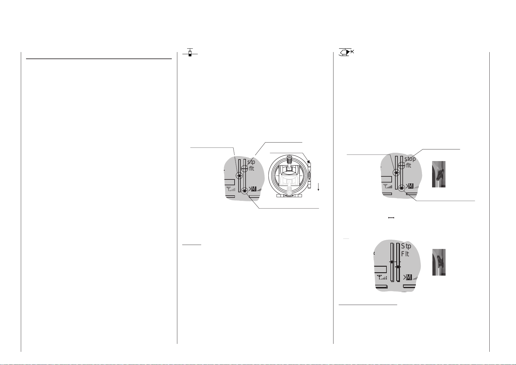
Digital trim
Functional description and description of C1 cut-off
Digital trim with visible and audible indicators
Both sticks are equipped for digital trimming. When
you give the trim lever a brief push (one „click“),
the neutral position of the associated stick channel
changes by one increment. If you hold the trim lever
in one direction, the trim value changes continuously
in the corresponding direction with increasing speed.
These changes can be made „audible“ by way of different frequency tones. This makes finding the midpoint during flight easy, without looking at the screen.
When the midpoint is overrun, a brief pause will be
inserted.
Current trim values are automatically stored when a
model memory change is made. Furthermore, digital trim exercises flight phase specific control within
a memory location (except for throttle/brake flaps
trim) – the socalled „C1“ (channel 1) control function.
These default settings can be altered to “global” in the
»Stick mode« menu, which is available as standard
on the
mc- 2 0 HoTT transmitter only, see pages
114 and 116.
This C1 trim includes yet another special function for
winged aircraft and helicopter models, it allows the
carburetor‘s idle setting to easily be found for a combustion motor.
Since the trim functions described in these instructions are only effective in the direction „Motor off“,
the presentation in the screen of your transmitter
may only change with respect to individual throttle or
Pitch-min positioning of the C1 stick in the „forward“
or „back“ direction, such as throttle/pitch „left stick“ or
„right stick“.
The illustrations in these instructions are always
based on „Throttle/Pitch right“ for both types of models and „Throttle back“ for winged aircraft and helicopters.
1. Winged models
C1 trimming has a special cut-off trim function intended especially for combustion motors. This cut-off trim
function is configured as follows: First put the motor
into a safe idle speed.
Now if you push C1 trim in a single motion toward its
„Motor cut-off“ direction until it is in its furthest travel
position then an additional end-position marker will
remain in the display. When the motor is restarted you
can again immediately set the last idle speed with a
single movement in the direction of „more gas“.
Last idle position
Current trim position
Ch 1 trim lever
stp
flt
Idle direction
M
Trim at motor OFF position
This cut-off trim will be deactivated when “None” is
entered on the “Motor at C1” line of the »Model type«
menu, see page 104.
Notice:
Since this trim function is only effective in the “Motor
off” direction, the display illustrated above will change
appropriately if the C1 stick’s control direction for
minimum throttle is changed from “back” to “front” (on
which the above illustration is based) in the “Motor at
C1” line of the “Basic Settings” menu.
2. Helicopter models
In addition to the „Cut-off trim“ function described
below in „Winged aircraft models“, C1 trimming also
has another characteristic which is made possible
by combining it with a so-called „Throttle limit“ function see page 127. As long as the throttle limit control – as standard the right-hand proportional rotary
control Lv2 on the right-hand side of the transmitter – remains in the „rear“ half of its travel path, i. e. in
the startup range, C1 trimming acts on the throttle
servo as idle trim and the indication for idle trim is visible in the screen‘s display:
Current trim position
stop
flt
Last idle position
Throttle limit control
M
Trim at motor OFF position
However, in contrast to winged aircraft models, the
position indicator ( ) will be hidden and any preset
idle position will be deleted when the throttle limit
control is in the „front-side“ half of its travel path.
Stp
Throttle limit control
Flt
M
Notice for helicopters:
C1 trimming affects only the throttle servo, not the
pitch servo. Notice also that the helicopter throttle
servo must be connected to receiver output 6, see
receiver layout on page 75!
70
Digital trim
Page 71

71For your notes
Page 72
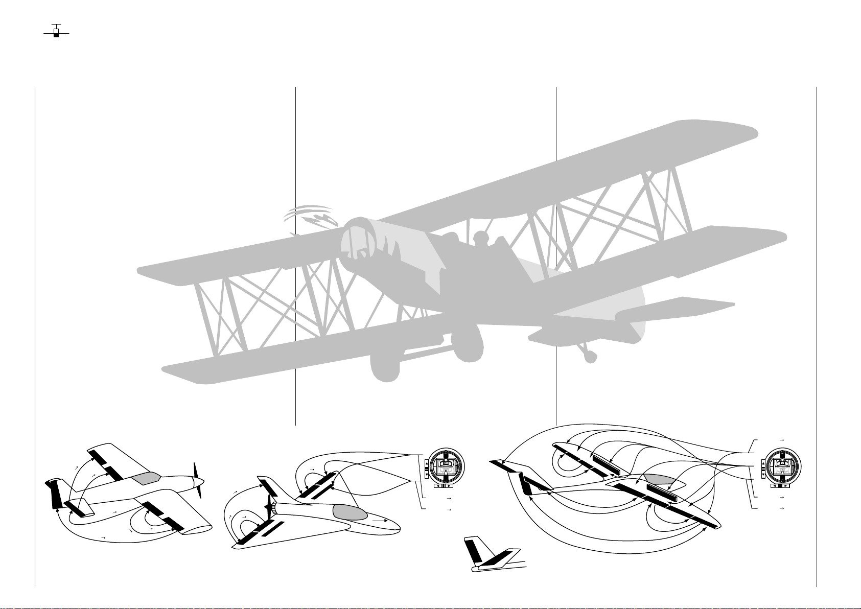
Winged models
Convenient support is provided for up to four aileron
servos and four flap servos on normal models or, for
V-tail and flying wing/delta models, up to two aileron/
elevator servos plus four flap servos.
The majority of motorized and glider models belong
to the tail unit type “normal” and are equipped with
one servo each for elevator, rudder and ailerons
in addition to a motor throttle or electronic speed
controller (or for brake flaps in the case of a glider
model). Beyond this, tail unit type “2 HR Sv 3+8” permits the connection of two elevator servos to receiver
outputs 3 and 8.
“V-tail” is to be selected from the »Model type« menu
if the model has a V-tail instead of a “normal” tail. This
V-tail option provides coupled control functions for
elevator and rudder such that both tail flaps – each
controlled by a separate servo – are able to handle
both elevator and rudder functionality.
For delta and flying wing aircraft models, aileron and
elevator functionality is affected by way of a common
rudder flap on the trailing edge of each side (right and
left) of the wing. The program contains appropriate
mixer functions for both servos.
If ailerons, and conditionally the flaps, are each actuated with two separate servos then settings can be
made for differentiated control of all aileron and flap
pairs in the »Wing mixers« menu, i. e. settings for
downward rudder throw independent of upward throw.
And finally, the ideal method of controlling flap positions is to use one of the two INC/DEC transmitter
controls, which are fitted as standard on the
mc- 2 0
HoTT transmitter only.
Alternatively, there is a phase-dependent trim func-
tion available for flaps, ailerons and elevators in the
»Phase trim« menu.
Up to 7 flight phases can be programmed into each of
the 20 respectively 24 model memory locations.
Except for C1 trim, digital trim will be stored on a
flight-phase basis. C1 trim permits easy location of a
carburetor idle setting.
Two timers are always available for flight operation.
The transmitter operating time expired since the last
battery charge is also displayed.
All transmitter controls and switches can be assigned
in the »Control adjust« menu to inputs 5 … 8 respectively 5 … 12 with almost no restrictions.
ons, rudder and elevators are separately programmable and each are convertible between the two variations on a specific flight-phase basis.
In addition to eight freely assignable linear mixers,
four curve mixers (»Free mixers« menu) and four
dual mixers (»Dual mixers« – available as standard
on the
mc- 2 0 HoTT transmitter only; can be un-
locked on the mc-16 HoTT as an extra-cost option),
flight-phase specific six-point curves are available for
control channel 1 (throttle / brake); see »Channel 1
curve« menu.
Depending on the number of wing servos, fixeddefinition mix and coupling functions can be selected
from a list in the »Wing mixers« menu.
• Multi-flap menu: control of flaps as ailerons, the influence aileron trim on flaps controlled as ailerons,
flap differentiation, flap function throw magnitude
for all aileron and flap pairs, ailerons controlled as
flaps, elevator mixer flaps
• Brake settings: butterfly, differential reduction,
elevator curves
• aileron rudder mixer
• flaps elevator mixer
The “Dual Rate” and “Exponential” functions for ailer-
AI, AI2
Brake
Brake
Brake
FL, FL2
Elevator
e
l
A
r
o
t
a
v
e
l
v
E
e
l
E
Winged models
72
Airbrake-Function 1
AI
n
o
r
FL
p
a
l
F
r
o
t
a
FL
r
o
t
a
v
e
l
E
A
p
a
l
F
F
i
l
e
l
a
r
o
p
n
A
i
l
e
r
o
n
A
i
l
e
r
o
R
u
d
n
d
e
r
AI
p
F
a
l
r
e
d
d
u
R
n
o
r
e
l
i
A
t
o
r
a
v
e
l
E
F
l
a
p
r
o
p
t
a
a
l
v
F
e
l
E
right
F
l
a
n
p
o
r
e
l
i
A
left
Airbrake
Airbrake
Flap
Elevator
Rudder/Elevator
left
V-Tail
right
AI
AI2
A
I
F
L
FL
A
I
FL2
L
F
FL2
E
L
F
L
E
L
F
L
RU AI
EL AI
FL
F
L
A
I
AI2
F
L
A
I
AI
Page 73
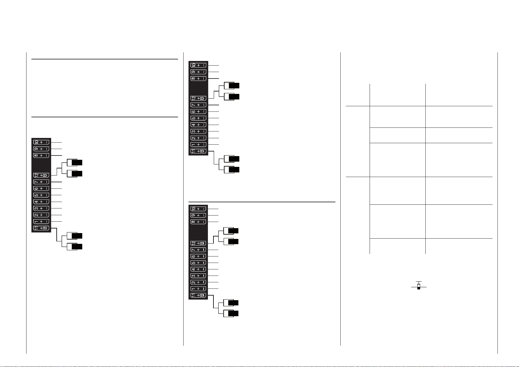
Installation notices
Servos MUST be connected to the receiver in the
sequence illustrated here.
Outputs which are not used are simply left empty.
Also be sure to follow the notices on the next
pages.
Winged aircraft with and without motor having up
to 4 aileron servos and up to 4 flap servos …
… and tail plane type “normal” or “2 elevator
servos”
Free or right flap 2 or aux. function
Free or left flap 2 or aux. function
Free or 2nd elevator or aux. function
Free or right aileron 2 or aux. function
Receiver power supply
Right flap or free or aux. function
Flap or left flap
Right aileron or aux. function
Rudder
Elevator or 1st elevator
Aileron or left aileron
Airbrake or throttle servo
or speed controller (electric motor)
Receiver power supply
Free or left aileron 2 or aux. function
… and tail plane type “V tail unit”
Free or right flap 2 or aux. function
Free or left flap 2 or aux. function
Free or aux. function
Free or aux. function
Receiver power supply
Right flap or free or aux. function
Flap or left flap
Right aileron or aux. function
Right rudder / elevator
Left rudder / elevator
Aileron or left aileron
Airbrake or throttle servo
or speed controller (electric motor)
Receiver power supply
Free or aux. function
Delta/flying wing aircraft models with and without
motor having up to 4 aileron/elevator servos and
up to 4 flap/elevator servos
Free or aux. function or right flap 2 / elevator
Free or aux. function or left flap 2 / elevator
Free or aux. function
Free or aux. function
Receiver power supply
Free or right flap / elevator
Free or left flap / elevator
Free or aux. function
Free or rudder
Right elevon
Left elevon
Airbrake or throttle servo
or speed controller (electric motor)
Receiver power supply
Free or aux. function
Because of orientation differences for installed servos and their rudder linkages, the actuating direction
of some servos may be initially backward. The table
below provides remedies.
Model
type
V tail Rudder and
Delta,
flying
wing
Servo
direction
wrong
elevator reversed
Rudder correct,
elevators reversed
Elevators correct,
rudder reversed
Elevator and aileron
reversed
Elevator correct,
aileron reversed
Aileron correct,
elevators reversed
Remedy
Reverse polarity of servos 3 & 4 in the »Servo
adjustment« menu
Swap servos 3 & 4 on
the receiver
Reverse polarity of servos 3 & 4 in the »Servo
adjustment« menu
AND swap them on the
receiver
Reverse the polarity
of servos 2 & 3 in the
»Servo adjustment«
menu
Reverse polarity of servos 2 & 3 in the »Servo
adjustment« menu
AND swap them on the
receiver
Swap servos 2 & 3 on
the receiver
All “program descriptions” for menus relevant to a
winged aircraft model are marked with a winged
aircraft symbol …
… so only these menus need to be dealt with to pro-
gram a winged aircraft model.
73Winged models - Receiver layout
Page 74
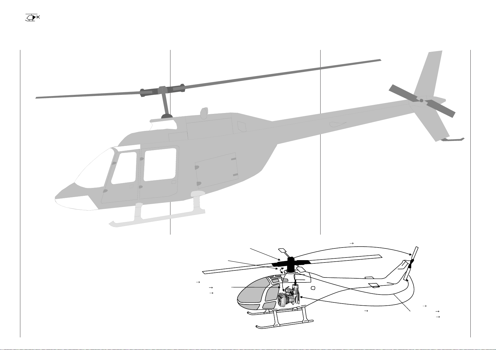
Helicopter models
The advanced developments incorporated into the
transmitter as well as those now in helicopter models
and their components like gyros, speed regulators,
rotor blades, etc. make it possible to master a helicopter even in 3D acrobatic flight. On the other hand,
a beginner needs only a few settings to get started
with hovered flight training then, step-by-step, take
advantage of HoTT transmitter features with increasing expertise.
All current model helicopters with one to four collective pitch servos can be operated using the programs
provided by the
mc-16 HoTT and m c- 20 HoTT.
Six flight phases plus autorotation are available within
a model memory, see menus »Control adjust«,
»Phase settings« and »Phase assignment«.
As with winged aircraft, here too, in addition to the
basic screen’s standard timers there are additional
timers as well as a lap counter with flight-phasedependent stopwatch functionality which are available for selection (menus »Timers (general)« and
»Fl. phase timers«).
Depending on the transmitter, it is possible to store
the digital trims in “flight phase specific” or “global”
form – for all flight phases; this does not apply to collective pitch / throttle trim. C1 trim permits easy location of an idle setting.
The control assignments for inputs 5 … 8 respectively 5 … 12 is made separately for each flight phase
(»Control adjust« menu).
A flight phase copy function is helpful during flight trials (»Copy / Erase« menu).
“Dual Rate” and “Exponential” functions can be coupled for roll, nick and tail rotor and programmable in
two variations in every flight phase.
There are 8 freely assignable linear mixers. There are
also 4 curve mixers that can be programed and these
can also be switched on or off, depending on the
flight phase, in the »MIX active/phase« menu. Four
dual mixers are also available (»Dual mixers« menu,
provided as standard on the
mc- 2 0 HoTT transmit-
ter only, but can be unlocked as an extra-cost option
in the mc-16 HoTT transmitter).
The »Helicopter mixer« menu provides flight-phasedependent 6-point curves for the non-linear characteristics pitch, throttle and tail rotor mixer as well as
two independent swashplate mixers each for roll and
nick. Independent of this, the control curve of the
channel 1 stick can be defined with up to a total of 6
points in every flight phase. The beginner will initially
only adapt the hover flight point to the control middle
for the non-linear characteristics.
Collective
Pitch Curve
Pre-programmed mixers in the »Helicopter mixer«
menu:
1. Pitch curve (6-point curve)
2. C1 throttle (6-point curve)
3. Channel 1 tail rotor (6-point curve)
4. Tail rotor throttle
5. Roll throttle
6. Roll tail rotor
7. Pitch-axis throttle
8. Pitch-axis tail rotor
9. Gyro suppression
10. Swashplate rotation
11. Swashplate limiter
The “Throttle limit” function (input “Lim.” in the »Con-
trol adjust« menu) allows the motor to be started in
any flight phase. The right-side proportional rotary
slider is assigned to input “Lim.” by default. This “throttle limiter” establishes – depending on its given position – the maximum possible throttle servo position.
This makes it possible for the motor to be controlled
in the idle range, if necessary even by the proportional regulator. The throttle curves become effective only
when the proportional regulator is pushed toward the
full throttle direction.
l
i
a
R
o
T
t
o
1
l
e
n
n
a
h
C
r
Swashplate
Rotation
Roll
Throttle
Throttle
Throttle
Roll
T
a
i
l
R
o
t
o
r
e
T
l
r
t
h
t
o
Tail Rotor
Pitch-Axis
Channel 1
Tail Rotor
Tail Rotor
Helicopter models
74
Pitch-Axis
Channel 1
Page 75
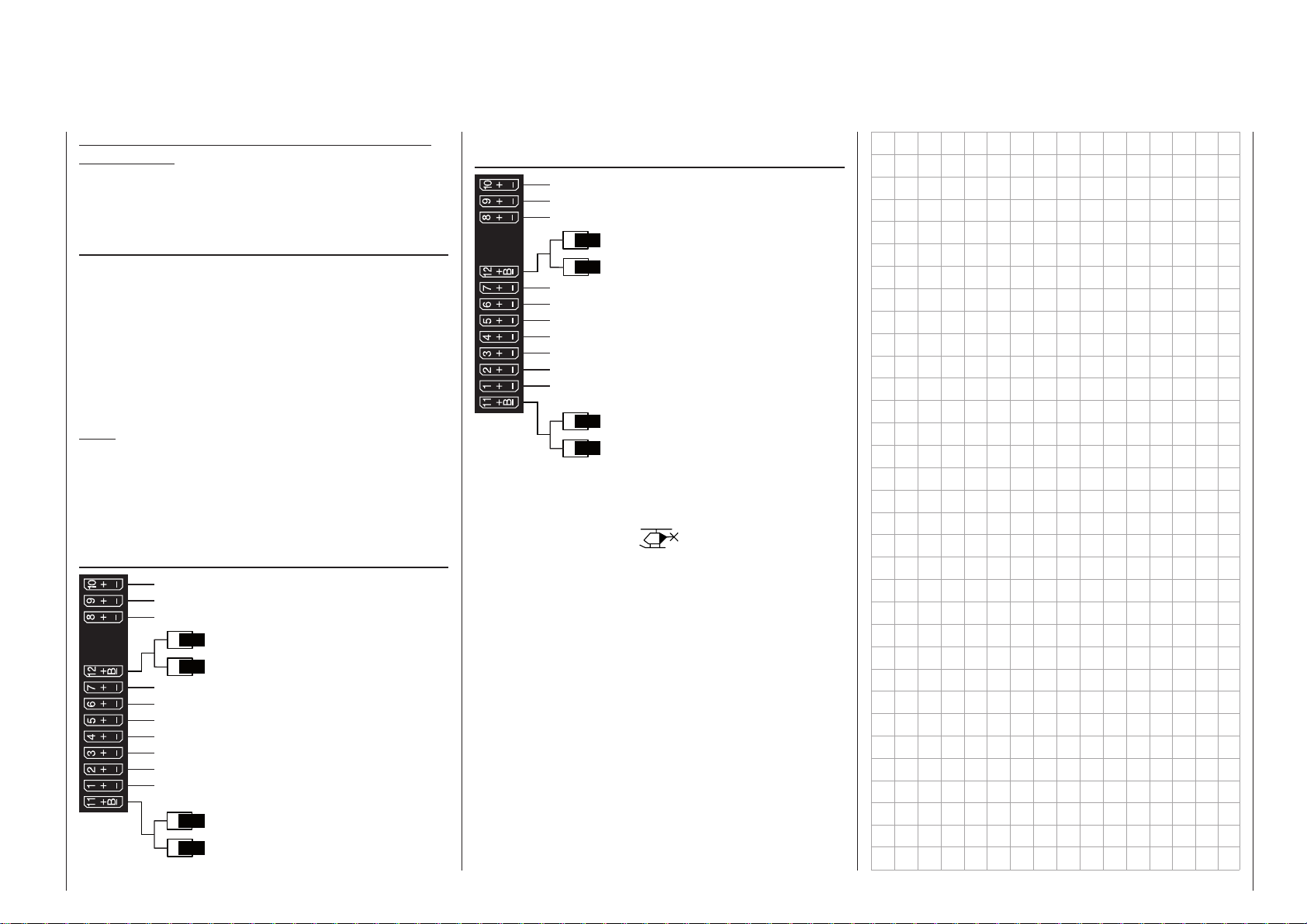
Notice for those transitioning from older Graupner systems:
In comparison to previous receiver layouts, servo
connector 1 (pitch servo) and servo connector 6
(throttle servo) have exchanged places.
Installation notices
Servos MUST be connected to the receiver in the
sequence illustrated here.
Outputs which are not used are simply left empty.
For more detailed information on each swashplate
type please refer to the »Helicopter type« menu,
described on page 108.
Also be sure to follow the notices on the next
pages.
Note:
A speed control is also to be connected to receiver
output “6” in order to take full advantage of the throttle
limiter’s convenience and safety features. See page
193 about this.
Receiver allocation for helicopter models with
1 to 3 swashplate servos
Free or aux. function
Free or aux. function
Free or speed governor or aux. function
Free or aux. function
Receiver power supply
Gyro gain
Throttle servo or speed controller
Free or aux. function
Tail rotor servo (gyro system)
Pitch-axis 1 servo
Roll 1 servo
Collective pitch or roll 2 or
Pitch-axis 2 servo
Receiver power supply
Receiver allocation for helicopter models with
4 swashplate servos
Free or aux. function
Free or aux. function
Free or speed governor or aux. function
Free or aux. function
Receiver power supply
Gyro gain
Throttle servo or speed controller
Pitch-axis 2 servo
Tail rotor servo (gyro system)
Pitch-axis 1 servo
Roll 1 servo
Roll 2 servo
Receiver power supply
Free or aux. function
All menus relevant to helicopter models are marked
in the „program descriptions“ section with a helicopter
symbol …
… so only these menus need to be dealt with to program a helicopter model.
Free or aux. function
75Helicopters - Receiver layout
Page 76

Detail program description
Loading a new memory location
Anyone who has worked through to this part of the
manual has certainly already tried out a bit of programming. Nevertheless a detailed description of
every menu should not be left out.
This section begins with the loading of a “free” memory location, a procedure which would be performed if
a new model was being “programmed”:
0:00
0:00
HoTT
0.0V
#01
0:00h
Stp
Flt
4.1V
M
From the basic display, a jump to the “Multi-function
list” is made with a tap on the center SET key of the
right four-way button. (The center ESC key of the left
four-way button will cause a jump back to the basic
display.) By default, when the multi-function list is
called for the first time after switching on the transmitter, the »Model select« menu option will be active
and displayed in inverse video. Otherwise use the
or selection keys of the left or right four-way
button to select the »Model select« menu option,
whereby the upper of the two following figures shows
a selection list for a fixed-wing model and the lower
shows the selection list for a helicopter model.
Model select
Copy / Erase
Suppress menus
Suppress models
Base setup model
Model type
Model select
Copy / Erase
Suppress menus
Suppress models
Base setup model
Helicopter type
Tap briefly on the center SET key of the right four-way
button to open this menu option:
01
02
03
04
05
06
free
free
free
free
free
R12
In the transmitter’s delivered state, the first model
memory is initialized to the “fixed-wing model” type
and the receiver in the delivery is “bound” to this
model. This is indicated by the pictogram of a fixedwing model aircraft in the second column from left,
and the receiver identification displayed at far right; in
the example above this is R12. If the model memory
is not “bound”, you will see “---” instead of the receiver
identification.
The remaining memory locations, marked with
“free”, are still unoccupied and therefore
also “non-bound”.
If you wish to program a fixed-wing model then,
after leaving the »Model select« menu with a tap
on the center ESC key of the left four-way button,
programming of the model can begin right away … or
now use the or keys of the left or right four-way
button to select one of the free memory locations …
01
02
03
04
05
06
free
free
free
free
free
R12
… and then tap on the center SET key of the right
four-way button to confirm the choice.
Afterward you will be prompted to select the basic
model type, i. e. either “winged model” or “helicopter
model”:
Select model type
Use the or keys of the left or right four-way
button to select the basic model type then tap on
the center SET key of the right four-way button. This
initializes the selected model memory with the selected model type and the display will return to the
base screen. The memory location is now accordingly
occupied.
Changing over to another model type is still possible if
you first erase this memory location (»Copy / Erase«
menu, page 80).
Notes:
• If the currently active model memory is to be
erased then immediately after the erase action
one of the two model types, “Winged” or “Heli”
must be defined. You cannot avoid this selection even if you switch the transmitter off. Only afterward the undesired occupation of that model
memory erase from another memory location.
If a non-active memory location is erased, it will
Program description - Loading a new memory location
76
Page 77

subsequently be marked as “free” in the
“Model select” menu.
• After the selected model memory is initialized with
the desired model type, the display will switch to
the base screen of the freshly occupied model
memory. At this time the warning …
BIND. N/A
OK
… will appear for several seconds as notification that a binding connection to a receiver is “not
available”. A brief tap on the center SET key of the
right four-way button will cause a direct jump to
the appropriate option:
Base setup model
Mod.name
Stick mode
module
DSC Output PPM10
HoTT
n/a
BD1
1
n/a
BD2
Further details about binding a receiver can be
found on page 87 or 95.
• The “BIND n/a” warning closes automatically, after
which the following warning also appears for a few
seconds …
Fail Safe
setup
t.b.d.
… will appear (also for just a few seconds) to indicate that no fail safe settings have yet been made.
More about this can be found on page 220.
• If the screen should display the warning …
Thr
too
high!
… then move the throttle stick, or the limiter for a
helicopter, (by default this is the right-side rotary
slider Lv2) into its idle position.
Whether or not this warning appears also depends
on the settings selected for the “Motor on C1” and
“Pitch min.” options in the »Model type« menu,
see page 104, or »Helicopter type« menu, see
page 108. For winged aircraft models, select
“None” to deactivate this message if you have no
motor to enter.
• If the transmitter already has occupied model memories then sub-menus of the »Copy /
Erase« menu will display a pictograph of the selected model type at the respective memory location followed by a blank line or the model name
which was entered in the »Basic settings, mod-
el« menu, page 86 or 94.
• If battery voltage is too low, the model switchover
cannot be made due to reasons of safety. An appropriate message will appear in the screen:
not possible now
voltage too low
As a basic principle, there are four different ways to
assign the four control functions, aileron, elevator,
rudder and throttle or brake flaps for winged models
as well as rolling, pitching, tail rotor and throttle/pitch
for helicopter models, to the two sticks. Just which of
these methods is used depends on the preferences of
the individual model pilot. This function is set for the
currently active model memory in the “Stick mode”
line of the »Basic settings, model« menu, page
86 or 94:
Base setup model
Mod.name
Stick mode
module
HoTT
n/a
1
n/a
DSC Output PPM10
BD1
BD2
If this setting is desired as a default for future models,
the setting can also be entered into the »General
basic settings« menu, page 269:
Basic settings
Own
Stick mode
1
Modulation HoTT
DSC Output
PPM10
SEL
It should be noted here once again that, in the interest of greatest flexibility in combination with the prevention of unintentional operating errors, no controls
are preassigned to control channels 5 … 8 respectively 5 … 12 by default.
This means that, in the system’s delivered state,
only servos attached to receiver outputs 1 … 4
can typically be operated by the two sticks and
that any servos attached to receiver connectors
5 … max. 12 will remain in their middle positions.
A newly initialized helicopter model is also able to
more-or-less move servo 6 – depending on the position of the right-side proportional rotary slider, which
is the default throttle limiter control. With either model
type, this situation will only change after appropriate
assignments have been made in the »Control ad-
just« menu.
On the other hand, if a newly initialized model memory is to be put into operation then it MUST first be
appropriately “connected” with one or more receivers
before the servos attached to the receiver/s can be
operated. More about this can be found in the section
“Binding” on page 87 or 95.
A fundamental description of programming steps for
a winged aircraft model can be found in the programming examples section beginning on 280, or for
helicopter models beginning on page 318.
The menu descriptions below are arranged in the
sequence individual menus are listed in the multi-
77Program description - Loading a new memory location
Page 78

function list. However, since the
mc-16 HoTT and
mc- 2 0 HoTT transmitter types covered by this
manual differ in their software structure as well as
their hardware features, these instructions always
indicate the “soft” differences between the individual
transmitter types at the start of a menu description,
as they are in the Contents. The key is as follows:
mc
16 20
Key:
16 applicable to mc-16 HoTT
20 applicable to mc- 2 0 HoTT
standard option
can be unlocked as an extra-cost option
Program description - Loading a new memory location
78
Page 79

Model select
Call up model 1 … 20 (mc-16) or 1 … 24 (m c-20)
mc
16 20
29 and, on the previous double-page, explanations
were provided for navigating to the multi-function list
and about how to make allocations for a new model
memory. At this point we now wish to begin with the
“normal” description of individual menu items in the
sequence they are arranged in the transmitter. Therefore we will begin with the menu …
Model select
As many as 20 respectively 24 complete model settings, including digital trim values for the trim buttons,
can be stored. Trimming is stored automatically such
that a switchover from one model to another does not
cause a loss of current trim settings. To the right of
the model number, each occupied model memory line
in this display shows a pictograph of the model type
as well as the model’s name entered for the model
in its »Basic settings, model« menu, page 86 or
94. The code, if present, for the receiver “bound”
to the model memory location will appear in right the
line.
This option is available as standard on
both transmitter types.
The basic operation of the transmitters
keys was explained on pages 28 and
Model select
Copy / Erase
Suppress menus
Suppress models
Base setup model
Model type
Model select
Copy / Erase
Suppress menus
Suppress models
Base setup model
Helicopter type
Select the »Model select« menu with the selection
keys of the left or right four-way button then briefly tap
on the SET key of the right four-way button.
Attention!
Switch-OFF
the Receiver first!
If this message appears, there is a telemetry connection to an operationally ready receiver system. Switch
that receiver system off:
01
02
03
04
05
06
Now, with the selection keys of the left or right
four-way button, select the desired model memory
from the list and activate it with a tap on the SET key.
A tap on the ESC key will cause a return to the previous menu page without activating a model change.
Notes:
• If, after a model change, the “Throttle too high”
warning appears, the throttle/pitch stick (C1) or the
throttle limiter – by default, the right-side proportional rotary slider – is too far in the full throttle direction.
• If a model change causes the message …
… to appear, then the throttle / collective pitch
stick (Ch1) or the throttle limiter – by default the
right-hand side-mounted proportional rotary slider – is too far in the direction of full-throttle.
GRAUBELE
ULTIMATE
STARLET
BELL47G
free
free
Thr
too
high!
R12
R12
R12
–––
• If a model change causes the message …
BIND. N/A
OK
… to appear then binding settings should be
checked.
• If a model change causes the message …
Fail Safe
setup
t.b.d.
… to appear then respective fail safe settings
should be checked.
• If battery voltage is too low, the model switchover
cannot be made due to reasons of safety. An appropriate message will appear in the screen:
not possible now
voltage too low
79Program description - Model select
Page 80
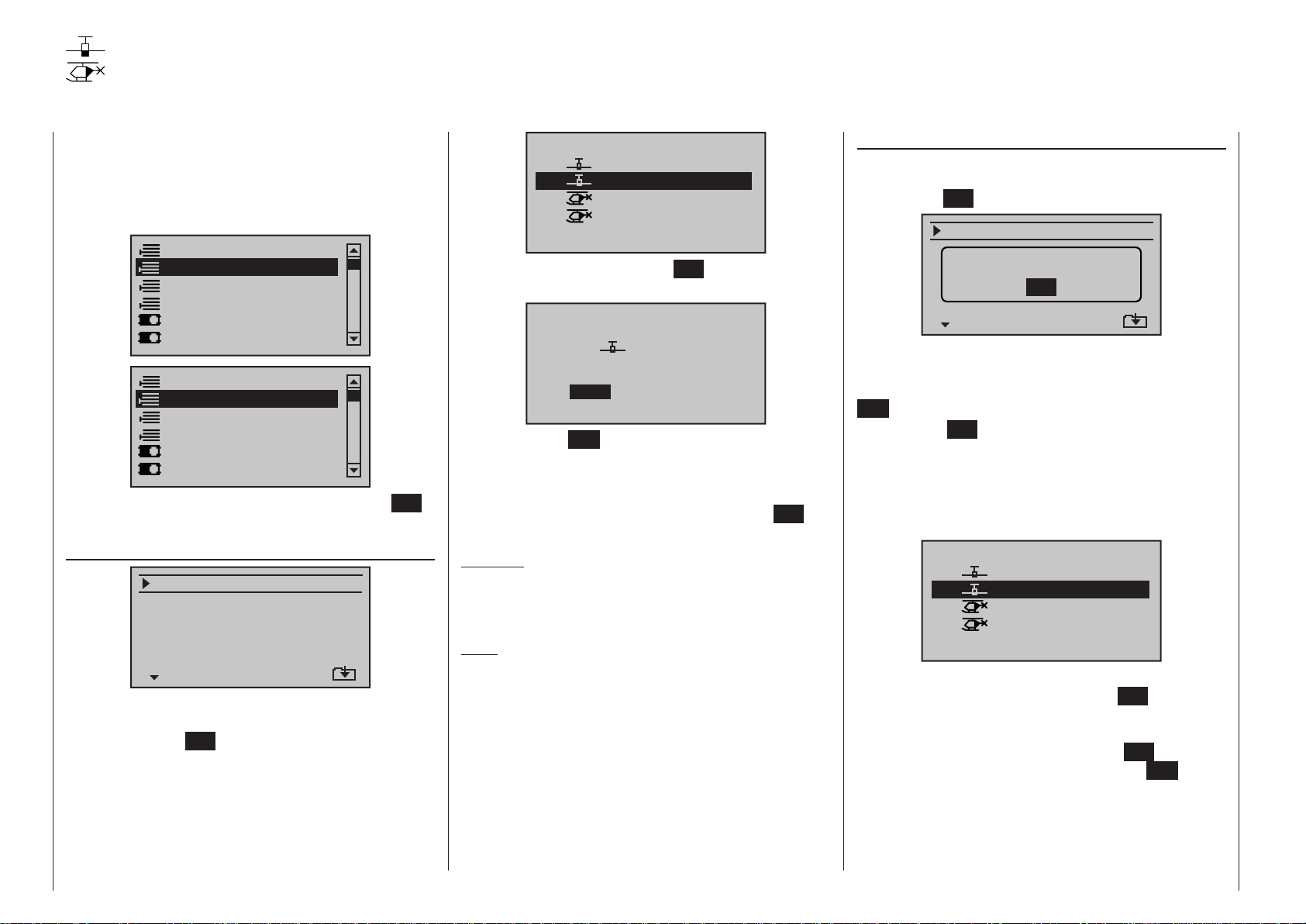
Copy / Erase
Erase model, copy model model, copy from or to SD card, copy flight phases
mc
16 20
Erase« option in the multi-function menu:
Open this menu option with a tap on the center SET
key of the four-way button pad:
Erase model
Select the “Erase model” sub-menu with the
selection keys of the left or right four-way button then
briefly tap on the SET key.
Choose the model to be erased with the selection keys of the left or right four-way button …
This option is available as standard on
both transmitter types.
Use the selection keys on the left or
right four-way button to select the »Copy /
Model select
Copy / Erase
Suppress menus
Suppress models
Base setup model
Model type
Model select
Copy / Erase
Suppress menus
Suppress models
Base setup model
Helicopter type
Erase model
Copy model–>model
Export to SD
Import from SD
Copy flight phase
=>
=>
=>
=>
=>
=>
=>
model to be erased :
01
02
03
04
… whereby another tap on the SET key will cause the
confirmation request …
… to appear. A NO response will cause the process
to be canceled and a return to the previous screen.
Selecting the YES response with the selection key
of the left or right four-way button followed by confirmation of the selection with a brief tap on the SET
key will erase the selected model memory.
Caution:
This erase process cannot be undone. All data in
the selected model memory will be erased completely.
Note:
If the currently active model memory is to be erased,
a model type “Winged” or “Heli” must be defined immediately after the erase process. If, however, an inactive memory location is erased, it will subsequently
appear in “Model select” list as “free”.
GRAUBELE
ULTIMATE
STARLET
BELL47G
Model really
01
to be erased?
NO
GRAUBELE
YES
R12
R12
R12
–––
Copy model model
Select the “Copy model model” sub-menu with the
selection keys of the left or right four-way button
then tap the SET key:
Erase model
C l l
SWITCHING RF OFF
Copy ligh phase
If the message shown above should appear, the
transmitter’s RF module is still active.
You can interrupt the process by pressing the central
ESC button of the left-hand four-way button.
Pressing the SET button of the right-hand four-way
button resumes the process. However, if the receiving
system is switched on, you should switch it off before
doing this.
Choose the model to be copied with the selection keys of the left or right four-way button …
Copy from model:
01
02
03
04
… then, following the change into the “Copy to model”
window caused by another tap on the SET key of the
right four-way button, the destination memory can be
selected with the selection keys of the left or right
four-way button. Yet another tap on the SET key will
then confirm the copy process or a tap on ESC key
will cause the copy to be cancelled. A memory location which is already occupied can be overwritten.
OK
GRAUBELE
ULTIMATE
STARLET
BELL47G
=>
R12
R12
R12
–––
Program description - Copy / Erase
80
Page 81
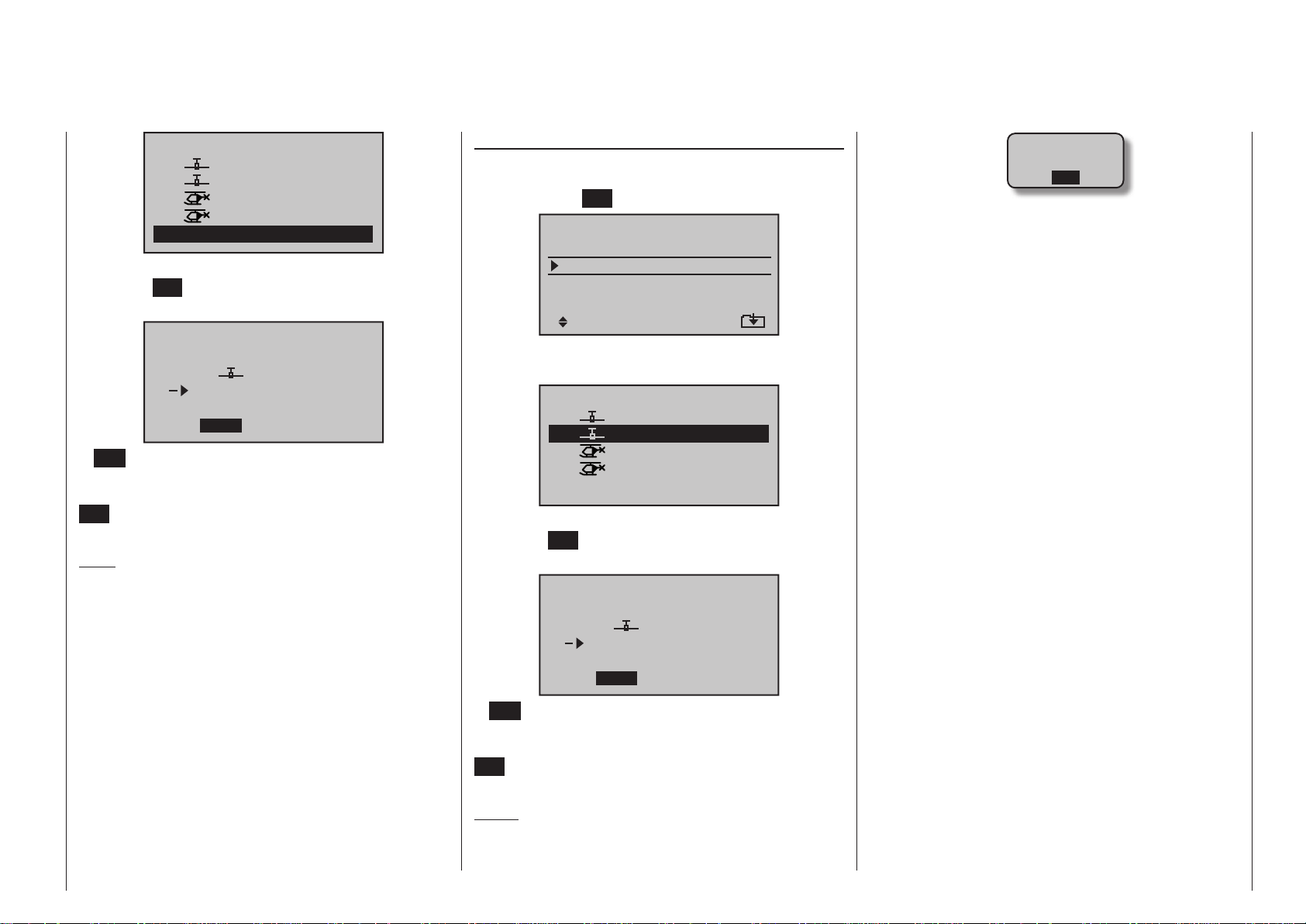
Copy to model:
01
02
03
04
05
GRAUBELE
ULTIMATE
STARLET
BELL47G
free
R12
R12
R12
–––
After confirming the selected model memory with a
tap on the SET key, a confirmation request will appear:
Modell really
01
03
ULTIMATE
free
to be copied?
NO
YES
A NO response will cancel the process and return
the screen to the originating screen. If the YES
response is selected and confirmed with a tap on the
SET key then the selected source model will be cop-
ied into the selected model memory destination.
Note:
In addition to model data, binding data is also copied
by this process. This means that a receiver system
which was/is bound to the original model memory can
also be operated by its copy in the SAME transmitter
without establishing the bond again.
Exporting to SD card
Use the selection keys of the left or right fourway button to select the “Export to SD” sub-menu
then tap on the SET key.
Erase model
Copy model–>model
Export to SD
Import from SD
Copy flight phase
=>
=>
=>
=>
=>
=>
=>
Choose the model to be exported with the selection keys of the left or right four-way button …
export to SD-CARD:
01
02
03
04
GRAUBELE
ULTIMATE
STARLET
BELL47G
R12
R12
R12
–––
After confirming the selected model memory with a
tap on the SET key, a confirmation request will appear:
modell
01
ULTIMATE
SD-CARD
export ?
NO
YES
SD-CARD
INSERT
OK
… appears instead of a screen for model selection, there is no SD card in the transmitter’s card
slot, see page 24.
• In addition to model data, binding data is also copied by this process. This means that a receiver
system which was/is bound to the original model
memory can also be operated in the SAME transmitter by its copy without establishing the bond
again.
• An exported fixed-wing model will be stored on the
memory card in the \\Models\mc-16 respectively \\Models\mc-20 folder with a filename format of
“aModelname.mdl” and a helicopter model with a
filename format of “hModelname.mdl”. On the other hand, if a “nameless” model is exported, its data
will be stored on the memory card under “aNoName.mdl” or “hNoName.mdl”, as appropriate.
• Some special characters that can be used in model names are subject to specific restrictions associated with the FAT or FAT32 file system used by
the memory cards and these special characters
will be replaced during the copy process with a tilde (~).
• A model file already on the memory having the
same name as the file to be copied will be overwritten without warning.
A NO response will cancel the process and return
the screen to the originating screen. If the YES
response is selected then confirmed with a tap on the
SET key, the selected model will be copied to the SD
card.
Notes:
• Should the notice …
81Program description - Copy / Erase
Page 82

Importing from SD card
Use the selection keys of the left or right fourway button to select the “Import from SD” sub-menu
then tap on the SET key.
Erase model
C d l d l
SWITCHING RF OFF
OK
Copy ligh phase
=>
>
>
>
>
>
>
If the message shown above should appear, the
transmitter’s RF module is still active.
You can interrupt the process by pressing the central
ESC button of the left-hand four-way button.
Pressing the SET button of the right-hand four-way
button resumes the process. However, if the receiving
system is switched on, you should switch it off before
doing this.
Select the model to be imported from the SD memory
card with the selection keys of the left or right
four-way button:
import from SD-CARD:
ALPINA
EXTRA
COBRA
BELL47G
11/03/10
11/03/11
11/03/11
11/03/12
Note:
The export date posted at the right end of each model
name line is represented in the format “year/month/
day”.
After another tap on the SET key of the right four-way
button, the “import from SD-CARD” window will appear. Now the destination memory location can be
selected with the selection keys of the left or right
four-way button then confirmed with a tap on the SET
Program description - Copy / Erase
82
key, or the process can be canceled with a tap on the
ESC key. A memory location which is already occu-
pied can be overwritten.
import to model:
01
02
03
04
05
GRAUBELE
ULTIMATE
STARLET
BELL47G
free
R12
R12
R12
–––
After confirming the selected model memory with a
tap on the SET key, a confirmation request will appear:
modell
ULTIMATE
03
free
import ?
NO
YES
A NO response will cancel the process and return
the screen to the originating screen. If the YES
response is selected and confirmed with a tap on the
SET key then the selected source model will be im-
ported into the selected destination model memory.
Notes:
• If the message …
SD-CARD
INSERT
OK
… appears instead of a screen for model selection, there is no SD card in the transmitter’s card
slot, see page 24.
• In addition to model data, binding data is also imported by this process. This means that a receiver
system which was/is bound to the original model
memory can also be operated in the SAME transmitter by its copy without establishing the bond
again.
• In principle the model memories of the mx-20 and
mc- 2 0 transmitters are compatible, BUT:
If you wish to carry out an “Import from SD card” in
the other transmitter you must first copy or move
the model memory concerned to the appropriate
folder on a PC. For example: from \\Models\mc-20
to \\Models\mx-20, or vice versa.
C A U T I O N :
After you have carried out an “Import from SD
card” it is absolutely essential to check all the
model functions with great care. Note also that the
transmitter control and switch functions may need
to be adjusted to suit the new transmitter.
Copy flight phase
Select the “Copy flight phase” sub-menu with the
selection keys of the left or right four-way button then
tap on the SET key.
Erase model
Copy model–>model
Export to SD
Import from SD
Copy flight phase
In the “Copy flight phase” sub-menu …
Copy from phase:
1
3
5
2
4
6
7
… the flight phase to be copied (1 … 7 for fixed-wing
models or 1 … 6 for helicopter models) is selected
with the selection keys of the left or right four-way
button then confirmed with a brief tap on the SET
key of the right four-way button. In the next window to
=>
=>
=>
=>
=>
=
=>
Page 83

appear …
Copy to phase:
1
3
5
7
… a destination must be selected and it must be confirmed too. Another confirmation request will follow:
Phase to:
1 Normal
to be copied?
2
4
6
2 Launch
NO
A NO response will cancel the process and return
the screen to the originating screen. If the YES
response is selected and confirmed with a tap on the
SET key then the selected source model will be im-
ported into the selected destination model memory.
YES
83Program description - Copy / Erase
Page 84

Suppress menus
Suppression of menus in the multifunction list
mc
16 20
press codes« option in the multi-function menu:
Open this menu option with a tap on the center SET
key of the four-way button pad.
This option is available as standard on
both transmitter types.
Use the selection keys on the left or
right four-way button to select the »Sup-
Model select
Copy / Erase
Suppress menus
Suppress models
Base setup model
Model type
Model select
Copy / Erase
Suppress menus
Suppress models
Base setup model
Helicopter type
Model select
Copy / Erase
Suppress models
Base setup model
Model type
Suppress: TOG
Model select
Copy / Erase
Suppress models
Base setup model
Helicopter type
Suppress: TOG
The option to be suppressed/displayed is selected
with the selection keys of the left or right four-way button then its status is switched over with a tap on the
center SET key of the right four-way button:
Model select
Copy / Erase
Suppress models
Base setup model
Model type
Suppress: TOG
Model select
Copy / Erase
Suppress models
Base setup model
Helicopter type
Suppress: TOG
This can reduce the multi-function list considerably, in
some cases to only a few menus, thus substantially
improving clarity of the multi-function list. Options are
not deactivated by being suppressed. They will simply
no longer appear in the list. This also blocks direct
access to these functions.
Tip:
If you do not wish to block access to the multi-function
list, in the interests of security we recommend that
you use this list to suppress the »Code lock« menu
from the multi-function list. This menu is available as
standard on the
can be unlocked as an extra-cost option on the mc-
mc- 2 0 HoTT transmitter only, but
16 HoTT transmitter. This setting also makes it a little
more difficult for any unauthorised person to block
access to the transmitter.
In the menu which then appears, menu items which
are no longer needed or those which should not be
changed, can be blocked from appearing in the multifunction list.
Program description - Suppress menus
84
Page 85
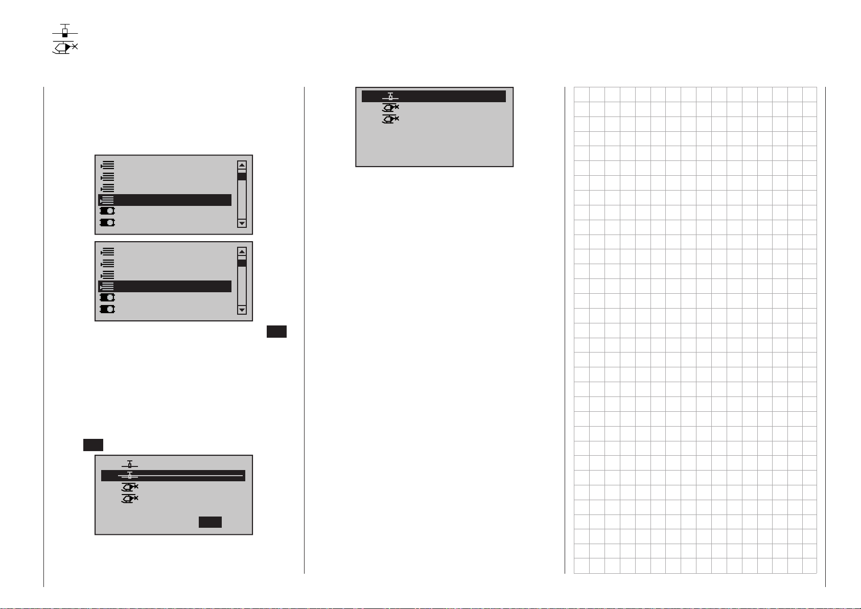
Suppress models
Suppression of model memory locations
mc
16 20
press models« option in the multi-function menu:
Open this menu option with a tap on the center SET
key of the four-way button pad.
Model memories which are rarely needed or to which
access is to be blocked for other reasons can be hidden from the model selection list. This also clarifies
the overview layout for model selection.
The model to be suppressed/displayed is selected
with the selection keys of the left or right four-way button then its status is switched over with a tap on the
center SET key of the right four-way button.
This option is available as standard on the
mc- 2 0 HoTT transmitter only.
Use the selection keys on the left or
right four-way button to select the »Sup-
Model select
Copy / Erase
Suppress menus
Suppress models
Base setup model
Model type
Model select
Copy / Erase
Suppress menus
Suppress models
Base setup model
Helicopter type
01
03
04
05
06
07
GRAUBELE
STARLET
BELL47G
free
free
free
R12
R12
–––
01
02
03
04
05
A model memory which is “stricken through” will no
longer appear in the »Model select« menu:
GRAUBELE
ULTIMATE
STARLET
BELL47G
free
Suppress:
R12
R12
R12
–––
TOG
85Program description - Suppress models
Page 86
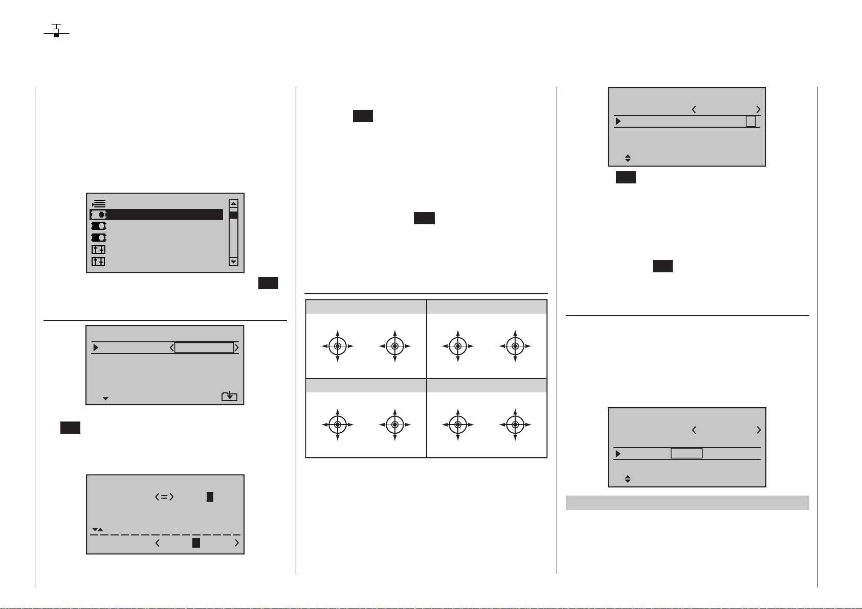
Base setup model
Model-specific base settings for winged aircraft models
mc
16 20
This option is available as standard on
both transmitter types.
Before programming specific parameters,
there are some basic settings to be made
which effect the currently active model memory.
Use the selection keys on the left or right four-
way button to select the »Base setup model« option
in the multi-function menu:
Suppress models
Base setup model
Model type
Servo adjustment
Stick mode
Control adjust
Open this menu option with a tap on the center SET
key of the four-way button pad:
Model name
Base setup model
Mod.name
Stick mode
module
HoTT
n/a
1
n/a
DSC Output PPM10
Change to the next screen page with a brief tap on
the SET key of the right four-way button. This will
open a screen of characters for entry of the model’s
name. A maximum of 9 characters can be used to
specify a model name.
!"#$%&’()�+,–./0123
456789:;
?@ AB CDE
FGHIJKLMNOPQRSTUVWX
YZ[¥]^_`abcdefghijk
Mod Name
GRAUB
Now the desired characters can be selected with the
Program description - Base setup models | Winged models
86
selection keys of the left four-way button. Move to the
next position to select the next character with a tap on
the center SET key of the right four-way button.
A simultaneous tap on the or keys of the
right four-way button (CLEAR) will place a space
character at the current position.
Positioning to any character position within the entry
field can be done with the keys of the right fourway button.
A return to the previous menu screen is accomplished
with a tap on the center ESC key of the left four-way
button.
A model name entered in this manner will appear in
the base screen of the »Model select« menu and in
the sub-menus of the »Copy / Erase« menu item.
Stick mode
MODE 1 (Throttle at rigth stick)
elev. down
left rudder
elev. up
MODE 3 (Throttle at right stick)
elev. down
left aileron
elev. up
right rudder
right aileron
full throttle
left aileron
idle
full throttle
left rudder
idle
MODE 2 (Throttle at left stick)
full throttle
right aileron
left rudder
MODE 4 (Throttle at left stick)
full throttle
right rudder
left aileron
right rudder
idle
right aileron
idle
elev. down
left aileron
elev. up
elev. down
left rudder
elev. up
right aileron
right rudder
There are four fundamental options for assigning the
four control functions (aileron, elevator, rudder and
throttle/brake flap) for a winged aircraft model to the
two sticks. Just which of these options is chosen depends on the individual preferences of the individual
model pilot.
Use the selection keys of the left or right fourway button to select the “Stick mode” line. The option
field will be framed.
Base setup model
Mod.name
Stick mode
module
HoTT
GRAUBELE
n/a
n/a
1
DSC Output PPM10
SEL
Tap on the SET key. The currently displayed stick
mode will be displayed in inverse video. Now use the
selection keys of the right four-way button to select
from among options 1 through 4.
A simultaneous tap on the or keys of the
right four-way button (CLEAR) will reset the display to
stick mode “1”.
Another tap on the SET key will again deactivate
option selection so a change to another line can be
affected.
Module
mc-16 HoTT and m c- 20 HoTT are fitted as
The
standard with a HoTT RF module. However, it is also
possible to switch to a non-Graupner|SJ external RF
module by software, if such a module is connected
to the transmitter. This is accomplished by using the
Select buttons of the left or right-hand four-way button
to move to the left, to the “Module select” value field:
Base setup model
Mod.name
Stick mode
module
Rcv Ch Map R12
GRAUBELE
HoTT
bind
BD1
1
n/a
n/a
BD2
HoTT
Graupner/SJ HoTT receivers must be “instructed” to
communicate exclusively with a certain model (memory) in a Graupner/SJ HoTT transmitter. This procedure is known as “binding” and must only be done
once for every new receiver/model-memory-location
Page 87
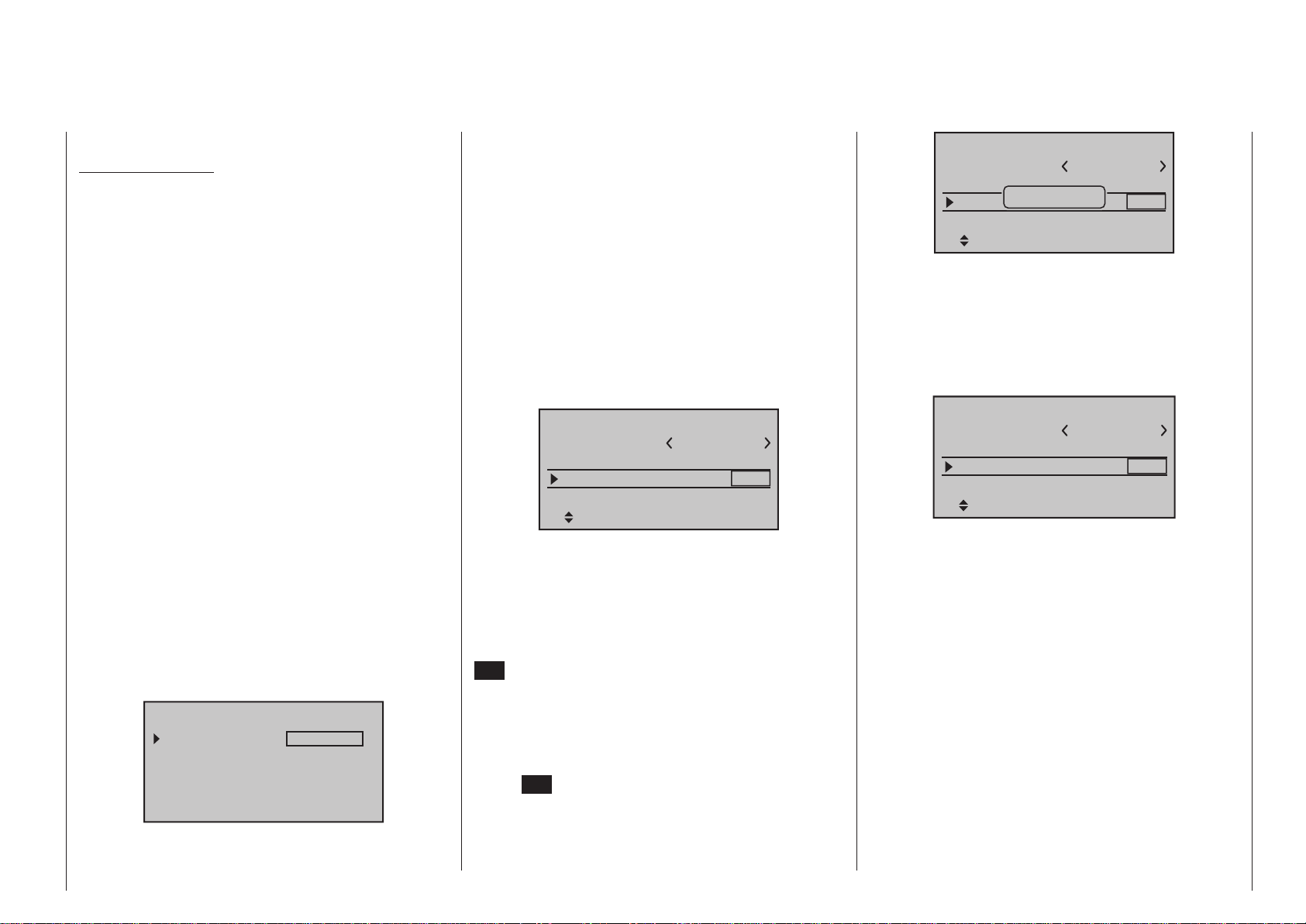
combination (and can be repeated anytime).
Important notices:
• During the binding procedure be sure the
transmitter’s antenna is always far enough
away from the receiver’s antenna. To be on the
safe side, keep them at least one meter apart.
Otherwise there is a risk of a faulty connection
to the return channel and malfunctions will result.
• When binding additional receivers, note that
any other – switched on – receivers already
bound to the transmitter will fall into Fail safe
mode during the transmitter-side “binding” period.
“Binding” multiple receivers per model
Multiple receivers per model can be bound if desired,
whereby respective
mc-16 HoTT and m c- 20
HoTT programs offer the potential for managing up to
two receivers directly and for dividing up the transmitter’s 8 or 12 control channels (max) in any arrangement among these receivers under menu control.
Refer to additional details further down in this section. First bind the receivers individually as described
below.
When the system is actually in use, the only receiver which creates a telemetry link to the transmitter is either the last receiver to be bound, or
the receiver which you selected in the “TEL.RCV.”
line of the »Telemetry« menu, for example:
TELEMETRY
TEL.RCV.
SETTING & DATA VIEW
SENSOR SELECT
RF STATUS VIEW
VOICE TRIGGER
RCV CH1
Any telemetry sensors which may be built into the
model should therefore be connected to this receiver
because the transmitter only receives and evaluates
data from the return channel of the receiver activated
on this line. The second, and all other receivers, operate in parallel but are fully independent in slave mode.
“Binding” transmitter and receiver
Use the selection keys of the left or right fourway button to move into the “Module” line:
The marker frame will be positioned by default to
the column for the next free binding channel. In the
example shown in the figure below, the marker frame
is positioned above the column label “BD2” because
the binding channel in the column labeled “BD1” is
already in use by default for the receiver which was
delivered with the set:
Base setup model
Mod.name
Stick mode
module
Rcv Ch Map R12
GRAUBELE
HoTT
bind
BD1
1
n/a
n/a
BD2
If already off, now switch the receiver on:
Receiver GR-16 and GR-24
The red LED on the receiver will blink..
Hold the SET button on the receiver pressed in for
about three seconds while the LED flashes red; it will
then flash red / green for a further three seconds. The
SET button on the receiver can now be released. As
long as this LED blinks red/green, the receiver is in
bind mode.
Now, within this 3 second period, start the so-called
“receiver binding” process for the receiver to the currently active model memory with a brief tap on the
center SET key of the right four-way button. At this
time, the screen’s display will blend in a message
window for the duration of the “binding” process.
Base setup model
Mod.name
Stick mode
modu
Finding...
Rcv Ch Map R12
GRAUBELE
1
d
n/a
n/a
BD1
BD2
If the receiver’s LED, again blinking red, changes
within about 10 seconds to continuous illumination
in green, the binding process has been successfully
completed. Your model-memory to receiver combination is now operationally ready. At this time the screen
will now display “ bind “ (bound) instead of “n/a” (not
attached), for example:
Base setup model
Mod.name
Stick mode
module
Rcv Ch Map R12
GRAUBELE
HoTT
bind
BD1
1
bind
R08
BD2
On the other hand, should the LED on the receiver
blink red for longer than about 10 seconds, the binding process has failed. In this case the screen will
continue to show the status as “n/a”. If this should
happen, try changing the position of antennas then
repeat the entire procedure.
Binding other receivers
The binding channel you have chosen is already
bound (as indicated by the “bind” status). This binding
is to be replaced by another. After initiating the RF
bind process, instead of displaying “BINDING”, the
message shown below appears:
87Program description - Base setup models | Winged models
Page 88
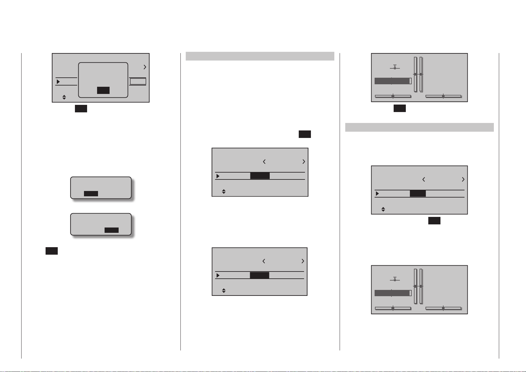
Base setup model
BD1
BELE
1
bind
R08
BD2
Mod.
Stick
modu
Rcv
RF
must be
OFF
OK
Press the central SET button of the right-hand fourway button to erase the message.
Drop down two lines in the screen and switch off the
RF module as described on the page in section “RF
module”. Afterward, return again to the “Module” line
and restart the binding process as described above.
Alternatively, the transmitter can be switched off
briefly then, after switching it back on again, respond
to the message window that appears …
Please select
RF on/off?
ON OFF
… with “OFF” …
Please select
RF on/off?
ON OFF
… then confirm the selection with a brief tap on the
center SET key of the right four-way button. From the
base screen jump again into the “Module” line of the
»Basic settings, model« menu and restart the binding process.
Dissolving a bond
Proceed as described above to initiate the binding
process but WITHOUT first putting a receiver in binding readiness.
EXT. (PPM signal at DSC socket)
If your transmitter is fitted with a non-Graupner|SJ
external RF module connected to the DSC / Data
socket, you can switch between the standard internal
HoTT RF module and the external module when you
switch model memories in the “Module” line by choosing either “HoTT”, “EXT.”, or “SP.”, as described in the
following section.
You can now use the arrow button of the right-hand
four-way button to move to the first Value field in the
“Module” line before pressing the central SET button
of the right-hand four-way button:
Base setup model
Mod.name
Stick mode
module
Rcv Ch Map R12
GRAUBELE
HoTT
bind
BD1
1
bind
R08
BD2
In the active Value field you should now use the Select buttons to choose “EXT.” or – if appropriate – the
“SP.” mode (described below) instead of “HoTT”.
When you select “EXT.”, the HoTT-specific value fields
are replaced by the modulation type already selected
in the “DSC output” line; see page 92:
Base setup model
Mod.name
Stick mode
module
EXT.PPM sig.
GRAUBELE
EXT.
1
PPM10
normal
The lines of the “Receiver output” and “Range test”
options (described below) are also suppressed, as
are all the HoTT-specific displays in the base display;
“PPM” is also superimposed instead of “HoTT”:
GRAUBELE
#01
Stp
Flt
0:00
0:00
4.0V
PPM
0:12h
Press the central SET button of the right-hand fourway button to conclude the Select process.
SP. (digital signal at Data socket)
However, if you require a special digital signal instead
of the analogue PPM signal for the non-Graupner|SJ
external RF module, then connect this to the DATA
socket and select “SP.” in the “Module” line:
Base setup model
Mod.name
Stick mode
module
GRAUBELE
SP.
1
BIND1
SP channel 6
Mod
BD
Once again, press the central SET button of the righthand four-way button to conclude the Select process.
The lines of the “Receiver output” and “Range test”
options (described below) are also suppressed, as
are all the HoTT-specific displays in the base display;
“SP.” is also superimposed instead of “HoTT”:
GRAUBELE
#01
Stp
Flt
0:00
0:00
4.0V
SP
0:12h
Program description - Base setup models | Winged models
88
Page 89
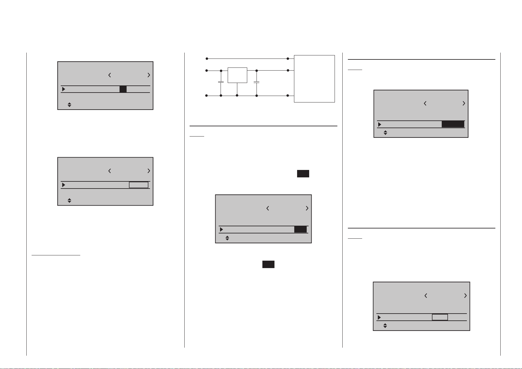
“Mode” column
Base setup model
Mod.name
Stick mode
module
GRAUBELE
SP.
1
1
BIND
SP channel 6
Mod
BD
In this column you select the transmission mode of
the external RF module:
• Mode “1”: 2-channel hopping
• Mode “2”: x-channel hopping
“BIND” column
Base setup model
Mod.name
Stick mode
module
GRAUBELE
SP.
1 BIND
1
SP channel 6
Mod
BD
The “BIND” column in the right-hand column can
be used to initiate the “Bind” process of the non-
Graupner|SJ system – the transmitter’s RF section
must be switched off when the transmitter is first
switched on.
Important notes:
• The output voltage of the DATA socket is
around 5 V, and must be reduced to the power supply voltage generally required by external digital RF modules (3 to max. 3.3 V). This is
accomplished using the circuit which is shown
here in diagrammatic form:
DATA S
Vcc IN = 5 V
DATA +
22µF/6.3 V
DATA -
Low Drop
Voltage
Regulator
GND
Vcc OUT = 3 ... 3.3 V
22µF/6.3 V
125000 baud signal
Vcc
SP.-MODULE
with
digital input signal
GND
• Servo travels must be limited to max. 128 %.
SP channels
Note:
This menu line is suppressed in the “Module” line if
you select “HoTT” or “EXT.”.
If necessary, use the Select buttons of the left or
right-hand four-way button to move to the “SP channels” line, then briefly press the central SET button of
the right-hand four-way button to activate the Value
window:
Base setup model
Mod.name
Stick mode
module
SP channel
GRAUBELE
SP.
1 BIND
1
6
SEL
You can now select “6” or “8” channels using the righthand Select buttons. The procedure is concluded by
again pressing the central SET button of the righthand four-way button.
At the transmitter this selection only affects the number of control channels transferred to the external RF
module via the DATA socket. If you choose “6”, then
these are control channels 1 … 6; if you choose “8”,
these are channels 1 … 8.
Simultaneously pressing the or buttons of
the right-hand four-way button (CLEAR) returns the
display to “6”.
EXT. PPM signal
Note:
This menu line is suppressed in the “Module” line if
you select “HoTT”.
Base setup model
Mod.name
Stick mode
module
EXT.PPM sig.
GRAUBELE
EXT.
1
PPM10
normal
SEL
Some RF modules which can be connected to the
DSC connector require an inverted input signal. Be
sure to follow the respective module’s installation
instructions for this.
The choice of “inverted” instead of the default preset
“normal” allows for appropriate adaptation of the provided PPM signal.
A simultaneous tap on the or keys of the
right four-way button (CLEAR) will reset the display to
“normal”.
Receiver channel mapping
Note:
This menu line is suppressed in the “Module” line if
you select “EXT.” or “SP. ”.
As long as there is at least one “bound” HoTT receiver in the “Module” line, the next line down will be the
“Rcv Ch map” line:
Base setup model
Mod.name
Stick mode
module
Rcv Ch Map R12
GRAUBELE
HoTT
bind
SET
1
bind
R08
SET
As already mentioned in the introduction to the section entitled “Binding receivers”, mc-16 HoTT and
89Program description - Base setup models | Winged models
Page 90
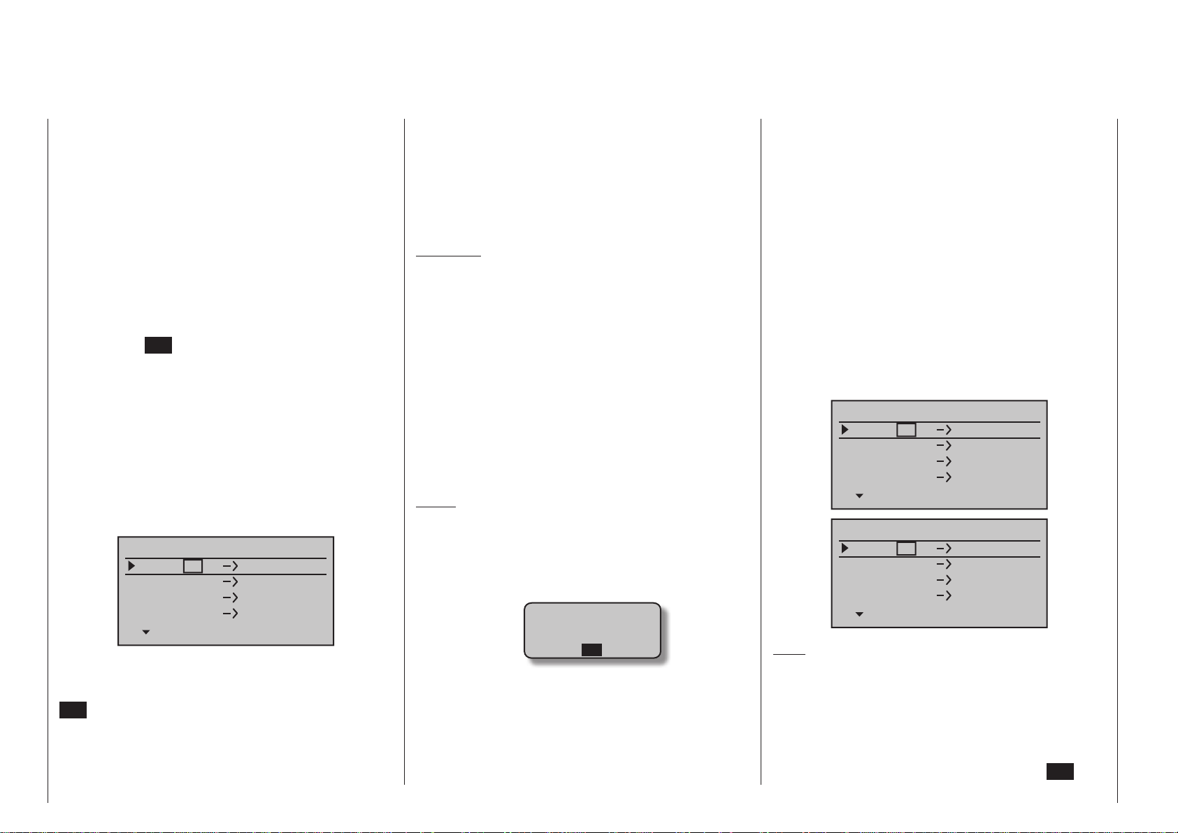
mc- 2 0 HoTT transmitters feature a menu point in
which the transmitter’s control channels can be redistributed in any way you like within one receiver,
and also include an option to distribute the transmitter’s control channels to a maximum of two receivers
in any arrangement you desire. These are the eight
standard / twelve optional control channels of the
mc-16 HoTT transmitter, and the standard twelve
control channels of the mc- 2 0 HoTT. This redistribution is termed “mapping” or “channel mapping”
(channel assignment) in the following section.
Select the receiver to be “mapped” with the selection
keys of the left or right four-way button then tap briefly
on the center SET key of the right four-way button.
Channel mapping within a receiver
This menu point provides a simple means of remapping the transmitter’s control channels in any
way you like, in a similar manner to the channel assignment function termed “Channel mapping” in the
»Tele metry« menu, as described on page 244. This
means that you can re-distribute the transmitter’s
control channels, which are present at the receiver
inputs, to the selected receiver’s outputs / servo sockets in any way you like:
Receiver CH – BIND1
In Ch
In Ch
In Ch
In Ch
After selection of the desired output with the selection
keys of the left or right four-way button, the appropriate value field will be framed. Briefly tap on the center
SET key of the right four-way button. The current
setting will be displayed in inverse video. Now use the
selection keys of the right four-way button to select
the desired input channel’s respective transmitter
output, see page 230.
Program description - Base setup models | Winged models
90
1
2
3
4
Out Ch
Out Ch
Out Ch
Out Ch
1
2
3
4
BUT CAUTION: If, for example, “2AIL” has been
specified in the “Aileron/camber flaps” line of the
»Model type« menu then the transmitter will have
allocated control function 2 (ailerons) to control chan-
nels 2 & 5 for the left and right ailerons. The corresponding receiver inputs to be assigned in this case
would be channels 2 & 5, refer to the example below.
Examples:
• You would like to control each aileron of a large
model with two or more servos.
Assign each of the appropriate outputs (servo connections) to one and the same input (control channel). In this case, depending on left or right wing,
as the respective input to one of the two default aileron control channels (2 or 5).
• You would like to control the rudder of a large
model with two or more servos.
Assign each of the appropriate outputs (servo
connections) to one and the same input (control
channel). In this case, the default rudder channel
(4), see figure right.
Notes:
• The maximum number of lines (outputs) available
corresponds to the maximum number of servos
which can be connected to the receiver in question.
• If you see the warning …
CAN‘T
RECEIVE
DATA
OK
… then there is no bound receiver within range. If
the case may be, switch your receiving system on.
• With the »Tx. output swap« option, which is available as standard on the
can be unlocked on the mc-16 HoTT transmitter
at extra cost, see page 230, the transmitter’s control functions can be interchanged in any way; it is
mc- 2 0 transmitter, and
also possible to assign multiple outputs to one and
the same control function. In the interests of clarity
however we strongly advise that you use only one
of these two options.
Channel assignment on second receiver
As already mentioned, the “Receiver channel mapping” menu point can be used to map (re-distribute)
the transmitter’s control channels in any way amongst
a maximum of two receivers; these are the eight
standard / twelve optional control channels of the
mc-16 HoTT transmitter, and the standard twelve
channels of the mc- 2 0 HoTT transmitter. In this
case the numbering of the outputs (servo sockets)
and the maximum number of lines (outputs) available
reflects the maximum number of servos which can be
connected to the receiver in question.
Receiver CH – BIND2
In Ch
In Ch
In Ch
In Ch 4
Receiver CH – BIND2
In Ch
In Ch
In Ch
In Ch
Note:
The upper screen-shot above shows the screen of
the standard mc-16 HoTT eight-channel transmit-
ter; the lower one the screen of the mc-20 HoTT
twelve-channel transmitter.
After selection of the desired output with the selection
keys of the left or right four-way button, the respective input field will be framed. Tap the center SET key
8
8
8
8
12
12
12
12
Out Ch
Out Ch
Out Ch
Out Ch
Out Ch
Out Ch
Out Ch
Out Ch
1
2
3
1
2
3
4
Page 91
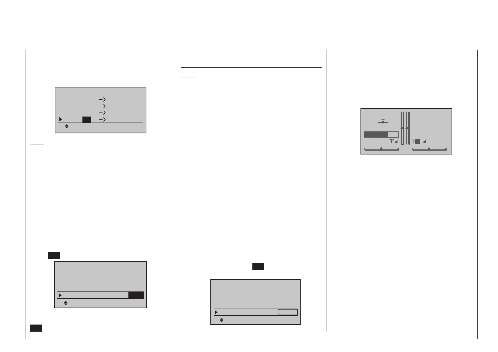
of the right four-way button. The current setting will
be displayed in inverse video. Now select the desired
input channel with the selection keys of the right fourway button. For example, suitable to the above rudder
example:
Receiver CH – BIND2
In Ch
In Ch
In Ch
In Ch
Note:
The maximum number of lines (outputs) available
reflects the maximum number of servos which can be
connected to the receiver in question.
RF transmit
This menu line provides an option for manually
switching the transmitter’s RF transmission on and off
to specific models while the transmitter is in operation. For example, to save power while a model is being programmed. If this line option was set to OFF,
it will be canceled (i. e. set to ON) the next time
the transmitter is switched on.
If necessary, use the selection keys of the left or
right four-way button to move into the “RF transmit“
line then activate the option with a brief tap on the
center SET button of the right four-way button:
4
4
4
4
Out Ch
Out Ch
Out Ch
Out Ch
1
2
3
4
Base setup model
Stick mode
module
HoTT
bind
Rcv Ch Map R12
1
bind
R08
RF transmit ON
SEL
The right selection keys can now be used to choose
between OFF and ON. Another tap on the center
SET key of the right four-way button will conclude the
entry.
Range test
Note:
This menu line is suppressed if you select “EXT.” or
“SP.” in the “Module” line.
The built-in range test reduces transmission power
to an extent that a functional test can be carried out
even within a distance of less than 100 m.
Perform a range test on the Graupner/SJ HoTT system according to the following instructions. If necessary, have someone assist you in carrying out the
range test.
1. Preferably, the receiver already bound to the transmitter should be installed into the model in its intended position.
2. Switch remote control on and wait for the green
LED to light up on the receiver/s. Now servo movements can be observed.
3. Place the model on a level surface (pavement,
low-cut grass or bare ground) such that receiver antennas are at least 15 cm above ground level. It may be necessary to put something under the
model to raise it up enough for this.
4. Hold the transmitter at hip level and at some distance from one’s body.
5. If necessary, use the selection keys of the
left or right four-way button to reach the “RF range
test” line in the menu then start range test mode
with a tap on the center SET key of the right fourway button:
Base setup model
module
Rcv Ch Map R12
RF transmit ON
RF Range Test 99sec
HoTT
bind
bind
R08
SEL
When the range test has been initiated, the transmitter’s transmission power will be significantly reduced and the green LED just to the right of the
main switch on the transmitter, marked RF, will
begin to blink; this will also be accompanied by
acoustic tones. At the same time, the timer in the
transmitter’s display will start counting down and
every 5 seconds a two-frequency tone will sound.
GRAUBELE
#01
TEST 76s
3.9V
2:22h
Five seconds prior to the end of the range test a
three-frequency tone will sound once every second. After expiration of the range test’s 99th second the transmitter will again be switched to full
output power and the LED just to the right of the
main switch on the transmitter will again illuminate
constantly.
6. Move away from the model while manipulating
the sticks during this timespan. If you notice an interruption anytime while still within a distance of
about 50 m, try to reproduce this malfunction.
7. If there is a motor in the model, it may be necessary to switch it on to further check noise immunity.
8. Continue moving away from the model until perfect
control is no longer possible.
9. Wait at this distance for the remainder of the test
period with the still-operationally-ready model
to expire. After the range test is ended it should
again respond correctly to all RC controls. If this is
not 100 % the case, do not use the system. Contact your area’s Graupner GmbH & Co. KG service
partner.
10. Perform the range test before each flight and, in
Stp
Flt
M
0:00
0:00
HoTT
5.5V
91Program description - Base setup models | Winged models
Page 92

doing so, simulate all servo movements which also
take place during flight. The range must always be
at 50 m on the ground in order to assure safe model operation.
Caution:
Never start the range test on the transmitter during normal operation of the model.
DSC output
If necessary, use the selection keys of the left or
right four-way button to switch to the “DSC Output”
line then, with a brief tap on the center SET key of the
right four-way button, activate the value window:
Base setup model
Rcv Ch Map R12
RF transmit ON
RF Range Test 99sec
DSC Output PPM10
Now you can use the right selection keys to choose
between four types of modulation “PPM10”, “PPM16”,
“PPM18” and “PPM24”. Touch the center SET key of
the right four-way button again to complete the entry.
This choice primarily influences the maximum number of control channels which can be attached to the
DSC (direct servo control) socket, and thus also available to a flight simulator or teacher/pupil system. By
selecting “PPM10” this will be control channels 1 … 5,
for “PPM16” channels 1 … 8, for “PPM18” channels 1
… 9 and for “PPM24” channels 1 … 12.
Cut off
Note:
This menu line is suppressed if “None” or “None/inv”
is selected for the “Motor on C1” line.
Depending on the “idle forward or back” choice made
in the “Motor on C1” line of the »Model type« menu,
Program description - Base setup models | Winged models
92
R08
SEL
this motor “cut off” option can be coupled to a switch
for throttling down a speed controller or to move a
servo on the carburetor of a motor to the OFF position. This option can be used on the
and mc- 2 0 HoTT transmitters as an emergency
OFF function as well as an alternative “cut-off trim”,
see “digital trims” on page 70.
This motor OFF position (Thr. CutOff) is specified in
the left column field over the column label SEL and its
value is to be established through trial and error.
However, the speed controller or throttle servo only
moves to the selected position when two conditions
are fulfilled: a switch is operated, and a particular
servo position or switching threshold is exceeded.
This is done by setting the desired servo position
(threshold value) into the middle column field, directly
over the column label STO, then selecting the appropriate ON/OFF switch function in the right column.
• If the percentage value specified for the middle
column is greater than the current servo position, i. e. the current servo position lies below the
threshold, the switchover will occur as soon as the
switch is put into its ON position.
• If the percentage value specified for the middle
column is less than the current servo position, i. e.
the current servo position is above the threshold,
the speed controller will initially reduce motor
speed or close the carburetor’s throttle servo only
to the extent dictated by the value in the left column as soon as the servo’s position once under-
runs the threshold (max. +150 %) after the switch
is changed over to its ON position.
The speed controller or throttle servo will remain in
this cut-off position only until the selected switch is
again changed over followed by a one-time throttle
servo or speed controller movement beyond the
preset threshold with the throttle/brake stick control.
The factory setting for the left column is -100 % for
mc-16 HoTT
the throttle servo “cut-off” position and a threshold of
+150 % servo position setting in the middle column.
Base setup model
RF transmit ON
RF Range Test 99sec
DSC Output PPM10
cut off
Programming procedure
To change the throttle servo’s preset “cut-off” position, tap on the center SET key of the right four-way
button. The current setting will be displayed in inverse
video. Now use the selection keys of the left or right
four-way button to set a value at which the motor is
reliably “off”. If a combustion motor is involved, be
sure the throttle servo does not perform mechanical
runout, e. g. -125 %:
Base setup model
RF transmit ON
RF Range Test 99sec
DSC Output PPM10
cut off
The – upper – preset value in the middle column
ensures the motor can be stopped, throughout the
maximum possible positioning range of the servo or
speed controller, alone by the switch to be assigned
in the right column.
However, if you wish to set a lower threshold, by
which an underrun will cause the throttle servo or
speed controller with closed switch to switch into the
cut-off position, reduce the preset servo travel from
+150 % by placing the throttle servo or speed controller into the desired position with the throttle/brake
stick then touch the center SET key of the right fourway button.
–100%
SEL
–125%
SEL
+150%
+150%
–––
STO
–––
STO
Page 93

Base setup model
RF transmit ON
RF Range Test 99sec
DSC Output PPM10
cut off
Finally, use the column at the right to specify a switch
with which you can cut off the motor directly (emergency) or which will be activated by the threshold.
Base setup model
RF transmit ON
RF Range Test 99sec
DSC Output PPM10
cut off
Notes:
• Be sure the throttle servo does not run out mechanically when the cut-off function is activated.
• A threshold over +100 % is reached by tempo rarily
increasing the travel for servo 1 in the »Servo ad-
justment« menu to over 100 % then, after storing
the threshold, change servo travel back to the
original value.
–125%
SEL
–125%
SEL
+100%
+100%
–––
STO
8
STO
time” – see page 163 – is always reset to the starting
value when the transmitter is switched on.
A simultaneous tap on the or keys of the
right four-way button (CLEAR) will reset the display to
“yes”.
Auto timer reset
Base setup model
RF Range Test 99sec
DSC Output PPM10
cut off
Auto timer reset yes
The “yes/no” setting made in this line determines
whether or not all of the transmitter’s timers (except
for “Model time” and “Transmitter operating time”) are
automatically reset to their given starting values when
the transmitter is switched on. In contrast, the “slot
+100%–125%
8
SEL
93Program description - Base setup models | Winged models
Page 94

Base setup model
Model-specific base settings for helicopter models
mc
16 20
This option is available as standard on
both transmitter types.
Before programming specific parameters,
there are some basic settings to be made
which effect the currently active model memory.
Use the selection keys on the left or right four-
way button to select the »Base setup model« option
in the multi-function menu:
selection keys of the left four-way button. Move to the
next position to select the next character with a tap on
the center SET key of the right four-way button.
A simultaneous tap on the or keys of the
right four-way button (CLEAR) will place a space
character at the current position.
Positioning to any character position within the entry
field can be done with the keys of the right fourway button.
Suppress models
Base setup model
Helicopter type
Servo adjustment
Stick mode
Control adjust
Open this menu option with a tap on the center SET
A return to the previous menu screen is accomplished
with a tap on the center ESC key of the left four-way
button.
A model name entered in this manner will appear in
the base screen of the »Model select« menu and in
the sub-menus of the »Copy / Erase« menu item.
Stick mode
key of the four-way button pad:
Model name
Base setup model
Mod.name
Stick mode
module
HoTT
n/a
1
n/a
DSC Output PPM10
Change to the next screen page with a brief tap on
the SET key of the right four-way button. This will
open a screen of characters for entry of the model’s
name. A maximum of 9 characters can be used to
specify a model name.
!"#$%&’()�+,–./0123
456789:;
FGHIJKL MNOPQRSTUVWX
YZ[¥]^_`abcdefghijk
?@ AB CDE
Basically there are four different ways to assign the
four helicopter control functions, roll, nick, tail rotor
and throttle/pitch to the two sticks. Just which of these
is used depends on the preferences of the individual
model pilot.
Use the selection keys of the left or right four-
Mod Name
STARL
way button to select the “Stick mode” line. The option
field will be framed.
Now the desired characters can be selected with the
Program description - Base setup models | Helicopter models
94
MODE 1 (Throttle at right stick)
pitch axis
tail rotor
pitch axis
MODE 3 (Throttle at right stick)
pitch axis
roll
pitch axis
throttle/pitch
tail rotor
roll
throttle/pitch
throttle/pitch
roll
tail rotor
throttle/pitch
MODE 2 (Throttle at left stick)
throttle/pitch
roll
tail rotor
throttle/pitch
MODE 4 (Throttle at left stick)
throttle/pitch
tail rotor
roll
throttle/pitch
tail rotor
roll
pitch axis
roll
pitch axis
pitch axis
tail rotor
pitch axis
roll
tail rotor
Base setup model
Mod.name
Stick mode
module
HoTT
STARLET
n/a
1
n/a
DSC Output PPM10
SEL
Tap on the SET key. The currently displayed stick
mode will be displayed in inverse video. Now use the
selection keys of the right four-way button to select
from among options 1 through 4.
A simultaneous tap on the or keys of the
right four-way button (CLEAR) will reset the display to
stick mode “1”.
Another tap on the SET key will again deactivate
option selection so a change to another line can be
affected.
Module
mc-16 HoTT and m c- 20 HoTT are fitted as
The
standard with a HoTT RF module. However, it is also
possible to switch to a non-Graupner|SJ external RF
module by software, if such a module is connected
to the transmitter. This is accomplished by using the
Select buttons of the left or right-hand four-way button
to move to the left, to the “Module select” value field:
Base setup model
HoTT
STARLET
bind
BD1
1
n/a
n/a
BD2
Mod.name
Stick mode
module
Rcv Ch Map R12
HoTT
Graupner/SJ HoTT receivers must be “instructed” to
communicate exclusively with a certain model (memory) in a Graupner/SJ HoTT transmitter. This procedure is known as “binding” and must only be done
once for every new receiver/model-memory-location
Page 95
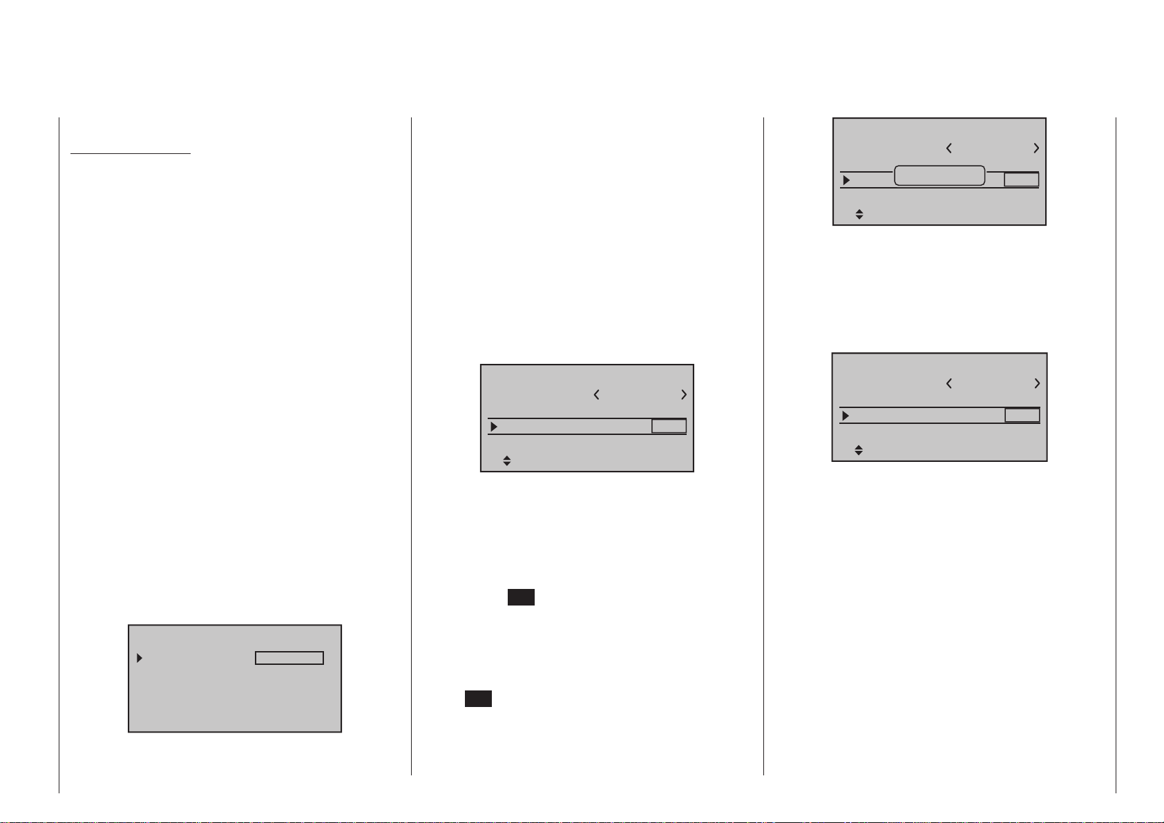
combination (and can be repeated anytime).
Important notices:
• During the binding procedure be sure the
transmitter’s antenna is always far enough
away from the receiver’s antenna. To be on the
safe side, keep them at least one meter apart.
Otherwise there is a risk of a faulty connection
to the return channel and malfunctions will result.
• When binding additional receivers, note that
any other – switched on – receivers already
bound to the transmitter will fall into Fail safe
mode during the transmitter-side “binding” period.
“Binding” multiple receivers per model
Multiple receivers per model can be bound if desired,
whereby respective
mc-16 HoTT and m c- 20
HoTT programs offer the potential for managing up to
two receivers directly and for dividing up the transmitter’s 8 or 12 control channels (max) in any arrangement among these receivers under menu control.
Refer to additional details further down in this section. First bind the receivers individually as described
below.
When the system is actually in use, the only receiver which creates a telemetry link to the transmitter is either the last receiver to be bound, or
the receiver which you selected in the “TEL.RCV.”
line of the »Telemetry« menu, for example:
TELEMETRY
TEL.RCV.
SETTING & DATA VIEW
SENSOR SELECT
RF STATUS VIEW
VOICE TRIGGER
RCV CH1
Any telemetry sensors which may be built into the
model should therefore be connected to this receiver
because the transmitter only receives and evaluates
data from the return channel of the receiver activated
on this line. The second, and all other receivers, operate in parallel but are fully independent in slave mode.
“Binding” transmitter and receiver
Use the selection keys of the left or right fourway button to move into the “Module” line:
The marker frame will be positioned by default to
the column for the next free binding channel. In the
example shown in the figure below, the marker frame
is positioned above the column label “BD2” because
the binding channel in the column labeled “BD1” is
already in use by default for the receiver which was
delivered with the set:
Base setup model
HoTT
STARLET
bind
BD1
1
n/a
n/a
BD2
Mod.name
Stick mode
module
Rcv Ch Map R12
If already off, now switch the receiver on:
Receiver GR-16 and GR-24
The red LED on the receiver will blink..
Press and hold the SET button on the receiver while
the LED continues to blink red for about 3 seconds,
then begins to blink red/green for about another 3
seconds. The SET button on the receiver can now be
released. As long as this LED blinks red/green, the
receiver is in bind mode.
Now, within this 3 second period, start the so-called
“receiver binding” process for the receiver to the currently active model memory with a brief tap on the
center SET key of the right four-way button. At this
time, the screen’s display will blend in a message
window for the duration of the “binding” process.
Base setup model
Mod.name
Stick mode
modu
Finding...
Rcv Ch Map R12
STARLET
d
BD1
1
n/a
n/a
BD2
If the receiver’s LED, again blinking red, changes
within about 10 seconds to continuous illumination
in green, the binding process has been successfully
completed. Your model-memory to receiver combination is now operationally ready. At this time the screen
will now display “ bind “ (bound) instead of “n/a” (not
attached), for example:
Base setup model
HoTT
STARLET
bind
bind
R08
BD1
1
BD2
Mod.name
Stick mode
module
Rcv Ch Map R12
On the other hand, should the LED on the receiver
blink red for longer than about 10 seconds, the binding process has failed. In this case the screen will
continue to show the status as “n/a”. If this should
happen, try changing the position of antennas then
repeat the entire procedure.
Binding other receivers
The binding channel you have chosen is already
bound (as indicated by the “bind” status). This binding
is to be replaced by another. After initiating the RF
bind process, instead of displaying “BINDING”, the
message shown below appears:
95Program description - Base setup models | Helicopter models
Page 96

Base setup model
Mod.
Stick
modu
Rcv
RF
must be
OFF
OK
1
bind
R08
BD1ETBD2
Press the central SET button of the right-hand fourway button to erase the message.
Drop down two lines in the screen and switch off the
RF module as described on the page in section “RF
module”. Afterward, return again to the “Module” line
and restart the binding process as described above.
Alternatively, the transmitter can be switched off
briefly then, after switching it back on again, respond
to the message window that appears …
Please select
RF on/off?
ON OFF
… with “OFF” …
Please select
RF on/off?
ON OFF
… then confirm the selection with a brief tap on the
center SET key of the right four-way button. From the
base screen jump again into the “Module” line of the
»Basic settings, model« menu and restart the binding process.
Dissolving a bond
Proceed as described above to initiate the binding
process but WITHOUT first putting a receiver in binding readiness.
EXT. (PPM signal at DSC socket)
If your transmitter is fitted with a non-Graupner|SJ
external RF module connected to the DSC / Data
socket, you can switch between the standard internal
HoTT RF module and the external module when you
switch model memories in the “Module” line by choosing either “HoTT”, “EXT.”, or “SP.”, as described in the
following section.
You can now use the arrow button of the right-hand
four-way button to move to the first Value field in the
“Module” line before pressing the central SET button
of the right-hand four-way button:
Base setup model
HoTT
STARLET
bind
bind
BD1
1
R08
BD2
Mod.name
Stick mode
module
Rcv Ch Map R12
In the active Value field you should now use the Select buttons to choose “EXT.” or – if appropriate – the
“SP.” mode (described below) instead of “HoTT”.
When you select “EXT.”, the HoTT-specific value fields
are replaced by the modulation type already selected
in the “DSC output” line; see page 100:
Base setup model
EXT.
STARLET
1
PPM10
normal
Mod.name
Stick mode
module
EXT.PPM sig.
The lines of the “Receiver output” and “Range test”
options (described below) are also suppressed, as
are all the HoTT-specific displays in the base display;
“PPM” is also superimposed instead of “HoTT”:
STARLET
#02
Stp
Flt
0:00
0:00
4.0V
PPM
0:12h
Press the central SET button of the right-hand fourway button to conclude the Select process.
SP. (digital signal at Data socket)
However, if you require a special digital signal instead
of the analogue PPM signal for the non-Graupner|SJ
external RF module, then connect this to the DATA
socket and select “SP.” in the “Module” line:
Base setup model
Mod.name
Stick mode
module
STARLET
SP.
1
BIND1
SP channel 6
BD
Mod
Once again, press the central SET button of the righthand four-way button to conclude the Select process.
The lines of the “Receiver output” and “Range test”
options (described below) are also suppressed, as
are all the HoTT-specific displays in the base display;
“SP.” is also superimposed instead of “HoTT”:
STARLET
#02
Stp
Flt
0:00
0:00
4.1V
SP
0:12h
Program description - Base setup models | Helicopter models
96
Page 97

“Mode” column
Base setup model
Mod.name
Stick mode
module
STARLET
SP.
1
1
BIND
SP channel 6
Mod
BD
In this column you select the transmission mode of
the external RF module:
• Mode “1”: 2-channel hopping
• Mode “2”: x-channel hopping
“BIND” column
Base setup model
Mod.name
Stick mode
module
STARLET
SP.
1
1 BIND
SP channel 6
Mod
BD
The “BIND” column in the right-hand column can
be used to initiate the “Bind” process of the non-
Graupner|SJ system – the transmitter’s RF section
must be switched off when the transmitter is first
switched on.
Important notes:
• The output voltage of the DATA socket is
around 5 V, and must be reduced to the power supply voltage generally required by external digital RF modules (3 to max. 3.3 V). This is
accomplished using the circuit which is shown
here in diagrammatic form:
DATA S
Vcc IN = 5 V
DATA +
22µF/6.3 V
DATA -
Low Drop
Voltage
Regulator
GND
Vcc OUT = 3 ... 3.3 V
22µF/6.3 V
125000 baud signal
Vcc
SP.-MODULE
with
digital input signal
GND
• Servo travels must be limited to max. 128 %.
SP channels
Note:
This menu line is suppressed in the “Module” line if
you select “HoTT” or “EXT.”.
If necessary, use the Select buttons of the left or
right-hand four-way button to move to the “SP channels” line, then briefly press the central SET button of
the right-hand four-way button to activate the Value
window:
Base setup model
Mod.name
Stick mode
module
SP channel
STARLET
SP.
1
1 BIND
6
SEL
You can now select “6” or “8” channels using the righthand Select buttons. The procedure is concluded by
again pressing the central SET button of the righthand four-way button.
At the transmitter this selection only affects the number of control channels transferred to the external RF
module via the DATA socket. If you choose “6”, then
these are control channels 1 … 6; if you choose “8”,
these are channels 1 … 8.
Simultaneously pressing the or buttons of
the right-hand four-way button (CLEAR) returns the
display to “6”.
EXT. PPM signal
Note:
This menu line is suppressed in the “Module” line if
you select “HoTT”.
Base setup model
EXT.
STARLET
1
PPM10
normal
Mod.name
Stick mode
module
EXT.PPM sig.
SEL
Some RF modules which can be connected to the
DSC connector require an inverted input signal. Be
sure to follow the respective module’s installation
instructions for this.
The choice of “inverted” instead of the default preset
“normal” allows for appropriate adaptation of the provided PPM signal.
A simultaneous tap on the or keys of the
right four-way button (CLEAR) will reset the display to
“normal”.
Receiver channel mapping
Note:
This menu line is suppressed in the “Module” line if
you select “EXT.” or “SP. ”.
As long as there is at least one “bound” HoTT receiver in the “Module” line, the next line down will be the
“Rcv Ch map” line:
Base setup model
HoTT
STARLET
bind
bind
SET
1
R08
SET
Mod.name
Stick mode
module
Rcv Ch Map R12
As already mentioned in the introduction to the section entitled “Binding receivers”, mc-16 HoTT and
97Program description - Base setup models | Helicopter models
Page 98

mc- 2 0 HoTT transmitters feature a menu point in
which the transmitter’s control channels can be redistributed in any way you like within one receiver,
and also include an option to distribute the transmitter’s control channels to a maximum of two receivers
in any arrangement you desire. These are the eight
standard / twelve optional control channels of the
mc-16 HoTT transmitter, and the standard twelve
control channels of the mc- 2 0 HoTT. This redistribution is termed “mapping” or “channel mapping”
(channel assignment) in the following section.
Select the receiver to be “mapped” with the selection
keys of the left or right four-way button then tap briefly
on the center SET key of the right four-way button.
Channel mapping within a receiver
This menu point provides a simple means of remapping the transmitter’s control channels in any
way you like, in a similar manner to the channel assignment function termed “Channel mapping” in the
»Tele metry« menu, as described on page 244. This
means that you can re-distribute the transmitter’s
control channels, which are present at the receiver
inputs, to the selected receiver’s outputs / servo sockets in any way you like:
Receiver CH – BIND1
In Ch
In Ch
In Ch
In Ch
After selection of the desired output with the selection
keys of the left or right four-way button, the appropriate value field will be framed. Briefly tap on the center
SET key of the right four-way button. The current
setting will be displayed in inverse video. Now use the
selection keys of the right four-way button to select
the desired input channel’s respective transmitter
output, see page 230.
Program description - Base setup models | Helicopter models
98
1
2
3
4
Out Ch
Out Ch
Out Ch
Out Ch
1
2
3
4
BUT CAUTION: If you wish to operate two servos
with one control function, for example such as transmitter control function 2 (roll) which is divided up into
control channels 1 & 2 for left and right roll servos
for the “3Sv(2Roll)” option in the »Helicopter type«
menu; then “map” the corresponding transmitter outputs, in this case for channels 1 & 2 (= inputs to the
receiver) accordingly.
Notes:
• The maximum number of lines (outputs) available
• If you see the warning …
• With the »Tx. output swap« option, which is avail-
Channel assignment on second receiver
As already mentioned, the “Receiver channel mapping” menu point can be used to map (re-distribute)
the transmitter’s control channels in any way amongst
a maximum of two receivers; these are the eight
standard / twelve optional control channels of the
mc-16 HoTT transmitter, and the standard twelve
channels of the mc- 2 0 HoTT transmitter. In this
case the numbering of the outputs (servo sockets)
corresponds to the maximum number of servos
which can be connected to the receiver in question.
CAN‘T
RECEIVE
DATA
OK
… then there is no bound receiver within range. If
the case may be, switch your receiving system on.
able as standard on the
can be unlocked on the mc-16 HoTT transmitter
at extra cost, see page 230, the transmitter’s control functions can be interchanged in any way; it is
also possible to assign multiple outputs to one and
the same control function. In the interests of clarity
however we strongly advise that you use only one
of these two options.
mc- 2 0 transmitter, and
and the maximum number of lines (outputs) available
reflects the maximum number of servos which can be
connected to the receiver in question.
Receiver CH – BIND2
In Ch
In Ch
In Ch
In Ch 4
Receiver CH – BIND2
In Ch
In Ch
In Ch
In Ch
Note:
The upper screen-shot above shows the screen of
the standard mc-16 HoTT eight-channel transmit-
ter; the lower one the screen of the mc-20 HoTT
twelve-channel transmitter.
After selection of the desired output with the selection
keys of the left or right four-way button, the respective input field will be framed. Tap the center SET key
of the right four-way button. The current setting will
be displayed in inverse video. Now select the desired
input channel with the selection keys of the right fourway button. For example, appropriate for the above
example with roll servos:
Receiver CH – BIND2
In Ch
In Ch
In Ch
In Ch
8
8
8
8
12
12
12
12
1
2
12
12
Out Ch
Out Ch
Out Ch
Out Ch
Out Ch
Out Ch
Out Ch
Out Ch
Out Ch
Out Ch
Out Ch
Out Ch
1
2
3
1
2
3
4
1
2
3
4
Page 99
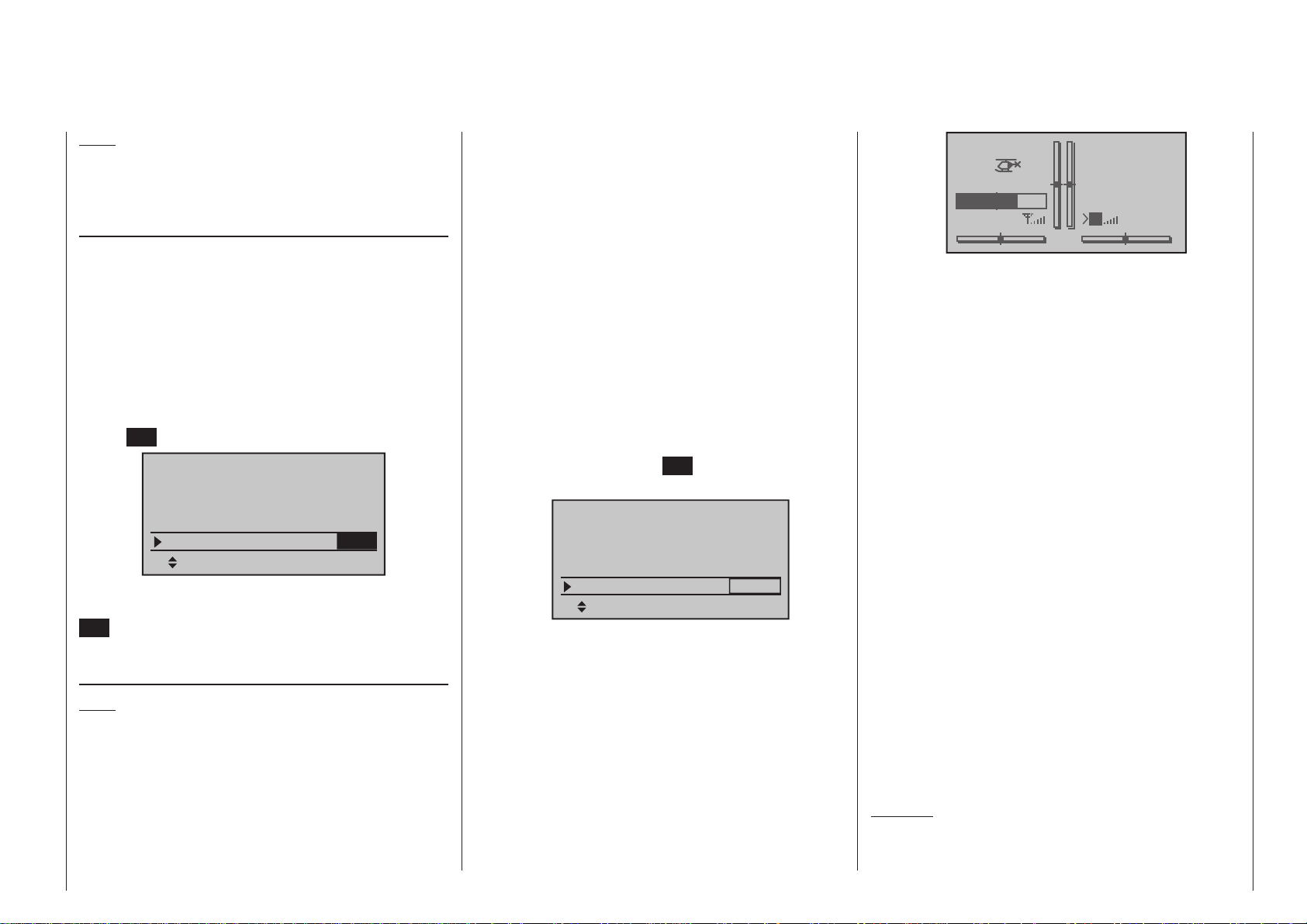
Note:
The maximum number of lines (outputs) available
reflects the maximum number of servos which can be
connected to the receiver in question.
RF transmit
This menu line provides an option for manually
switching the transmitter’s RF transmission on and off
to specific models while the transmitter is in operation. For example, to save power while a model is being programmed. If this line option was set to OFF,
it will be canceled (i. e. set to ON) the next time
the transmitter is switched on.
If necessary, use the selection keys of the left or
right four-way button to move into the “RF transmit“
line then activate the option with a brief tap on the
center SET button of the right four-way button:
Base setup model
Stick mode
module
HoTT
bind
Rcv Ch Map R12
1
bind
R08
RF transmit ON
SEL
The right selection keys can now be used to choose
between OFF and ON. Another tap on the center
SET key of the right four-way button will conclude the
entry.
Range test
Note:
This menu line is suppressed if you select “EXT.” or
“SP.” in the “Module” line.
The built-in range test reduces transmission power
to an extent that a functional test can be carried out
even within a distance of less than 100 m.
Perform a range test on the Graupner/SJ HoTT system according to the following instructions. If necessary, have someone assist you in carrying out the
range test.
1. Preferably, the receiver already bound to the transmitter should be installed into the model in its intended position.
2. Switch remote control on and wait for the green
LED to light up on the receiver/s. Now servo movements can be observed.
3. Place the model on a level surface (pavement,
low-cut grass or bare ground) such that receiver antennas are at least 15 cm above ground level. It may be necessary to put something under the
model to raise it up enough for this.
4. Hold the transmitter at hip level and at some distance from one’s body.
5. If necessary, use the selection keys of the
left or right four-way button to reach the “RF range
test” line in the menu then start range test mode
with a tap on the center SET key of the right fourway button:
Base setup model
module
Rcv Ch Map R12
RF transmit ON
RF Range Test 99sec
When the range test has been initiated, the transmitter’s transmission power will be significantly reduced and the green LED just to the right of the
main switch on the transmitter, marked RF, will
begin to blink; this will also be accompanied by
acoustic tones. At the same time, the timer in the
transmitter’s display will start counting down and
every 5 seconds a two-frequency tone will sound.
HoTT
bind
bind
R08
SEL
STARLET
#02
TEST 76s
3.9V
2:22h
Five seconds prior to the end of the range test a
three-frequency tone will sound once every second. After expiration of the range test’s 99th second the transmitter will again be switched to full
output power and the green LED just to the right of
the main switch on the transmitter will again illuminate constantly.
6. Move away from the model while manipulating
the sticks during this timespan. If you notice an interruption anytime while still within a distance of
about 50 m, try to reproduce this malfunction.
7. If there is a motor in the model, it may be necessary to switch it on to further check noise immunity.
8. Continue moving away from the model until perfect
control is no longer possible.
9. Wait at this distance for the remainder of the test
period with the still-operationally-ready model
to expire. After the range test is ended it should
again respond correctly to all RC controls. If this is
not 100 % the case, do not use the system. Contact your area’s Graupner GmbH & Co. KG service
partner.
10. Perform the range test before each flight and, in
doing so, simulate all servo movements which also
take place during flight. The range must always be
at 50 m on the ground in order to assure safe model operation.
Caution:
Never start the range test on the transmitter during normal operation of the model.
Stp
Flt
M
0:00
0:00
HoTT
5.5V
99Program description - Base setup models | Helicopter models
Page 100
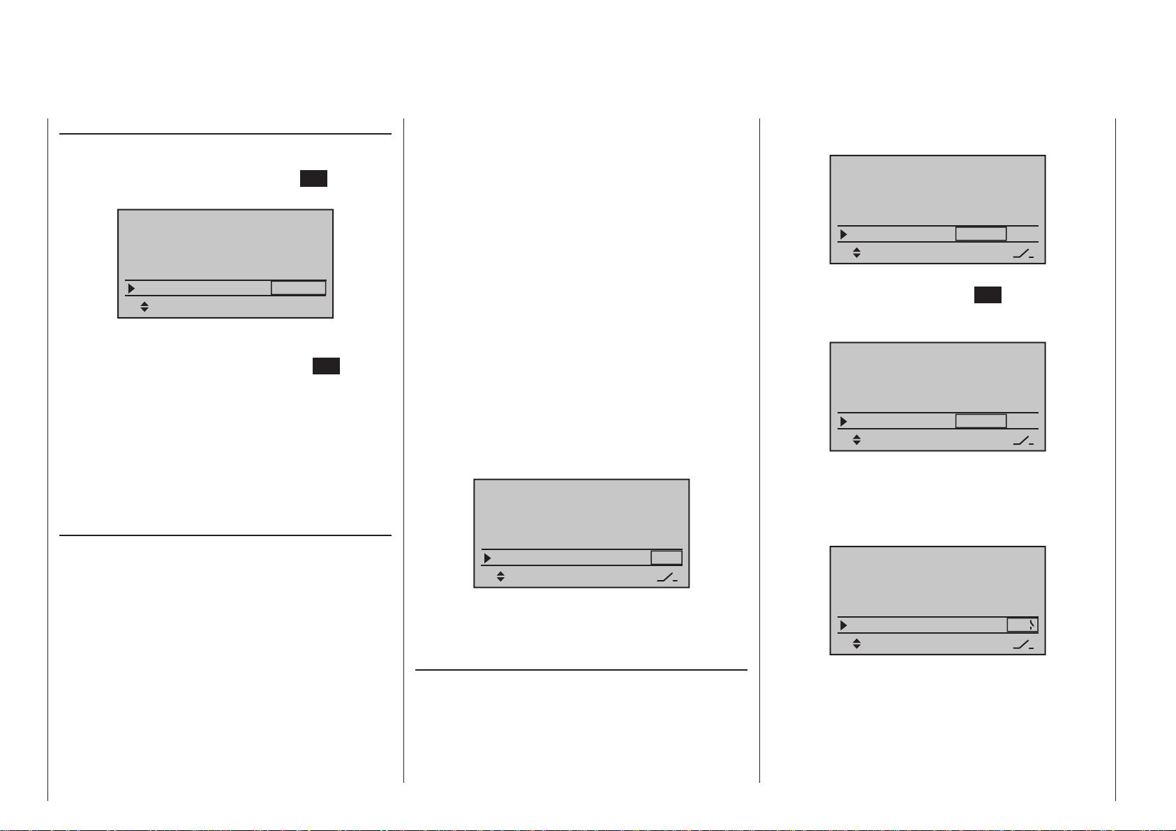
DSC output
If necessary, use the selection keys of the left or
right four-way button to switch to the “DSC Output”
line then, with a brief tap on the center SET key of the
right four-way button, activate the value window:
Base setup model
Rcv Ch Map R12
RF transmit ON
RF Range Test 99sec
DSC Output PPM10
Now you can use the right selection keys to choose
between four types of modulation “PPM10”, “PPM16”,
“PPM18” and “PPM24”. Touch the center SET key of
the right four-way button again to complete the entry.
This choice primarily influences the maximum number of control channels which can be attached to the
DSC (direct servo control) socket, and thus also available to a flight simulator or teacher/pupil system. By
selecting “PPM10” this will be control channels 1 … 5,
for “PPM16” channels 1 … 8, for “PPM18” channels 1
… 9 and for “PPM24” channels 1 … 12.
Autorotation
Autorotation is that state of descending flight in which
the pitch of main rotor blades are set such that the
rotor’s speed matches the natural forces of air flowing
through, like a windmill. The rotational energy stored
in the mass of the rotor by this process can then be
converted into upthrust by adjusting blade pitch, in
order to halt the descent and “rescue” the model.
Autorotation is a means by which real and model
helicopters are able to land safely in emergency situations, e. g. in the event of a motor failure. However,
the prerequisite for this is a well-trained pilot familiar
with the helicopter’s characteristics. Quick reaction
and good perceptiveness are necessary because
the rotor’s inertia can only be used once to generate
R08
SEL
recovery lift.
When this technique is evaluated during competi-
tions, the motor must be switched off for autorotation.
On the other hand, for training mode it is advantageous to keep the motor at idle for autorotation.
The Autorotation switch causes a switchover to the
autorotation flight phase in which control of “throttle”
and “pitch” are separate and all mixers which have
an effect on the throttle servo are switched off. Corresponding parameter settings are made in the »Heli-
copter mixer« (see text beginning page 188); refer
also to the “Principle of the Auto. C1 Pos.” topic which
follows.
The “Autorotation” name is permanently assigned to
this phase and it is included in the base screen and
the screens of all flight phase dependent menus. This
name can NOT be changed. It is only possible to assign a switch to this option at the right of this display,
as described on page 68. If a switch is assigned,
it will have absolute priority over all other flightphase switches:
Base setup model
RF transmit ON
RF Range Test 99sec
DSC Output PPM10
Autorotation
More about flight-phase programming can be found
in the text beginning on page 188 in the»Helicopter
mixer« section. Autorotation C1 position
The autorotation flight-phase can alternatively be
activated by a threshold point for the C1 throttle/pitch
stick. To do this, use the selection keys of the
left or right four-way button to move into the “Autorot.
C1-Pos.” line.
As soon as this display line has been selected, its
–––
value field, located above the column label STO will
be framed.
Base setup model
RF Range Test 99sec
DSC Output PPM10
Autorotation
Auto.C1 Pos.
Move the C1 stick into the desired threshold switchover position then tap the center SET key of the right
four-way button. The current value will be displayed,
e. g.:
Base setup model
RF Range Test 99sec
DSC Output PPM10
Autorotation
Auto.C1 Pos.
After this has been done, use the selection keys to
move into the column above the switch symbol then
assign a switch to this field, as described in section
“Physical control, switch and control switch assignments” on page 68:
Base setup model
RF Range Test 99sec
DSC Output PPM10
Autorotation
Auto.C1 Pos.
Once this activation switch is closed, the first occurrence of a threshold underrun will cause the program
to switch over to “Autorotation” and then remain independent of C1 position in this flight phase until the
activating switch, in this example switch 4, is again
“OFF”.
“Autorot. C1-Pos.” has precedence over all other
–66%
–66%
0%
STO
STO
STO
–––
–––
–––
–––
–––
9
Program description - Base setup models | Helicopter models
100
 Loading...