

Page 1

No. S1002.mz-12 HoTT. USA
mz-12
OPERATING INSTRUCTION
Prior to use, please read this manual thoroughly.
Keep this manual in a convenient place for quick and easy reference.
Page 2
Contents
3P
3P
3P
3P
3P
3P
3P
3P
3P
3P
4P
5P
5P
5P
5P
6~8P
8P
8P
8~9P
7. Wing mix (AIRCRAFT)
- Diff aile
- Diff ap
- Aile->rudd
- Aile->ap
- Brak->elev
- Brak->ap
- Brak->aile
- Elev->ap
- Elev->aile
- Flap->elev
- Flap->aile
- Diff->red
8. Heli mix (Helicopter)
- Ptch
- Pitc-thro
- Pitc-rudd
- Rudd-thro
- Aile-thro
- Elev-thro
- Gyro
- Swash lim
- Governor 8ch
- Governor rate
9. Free mix (Aircraft and Helicopter)
10. Swash mix (Helicopter)
11. Basic sett (Aircraft and Helicopter)
- Batt type
- Batt warning
- Touch sense
- Contrast
- Display light
- RF contry
- Voice volume
- Beep volume
12. Fail safe (Aircraft and Helicopter)
13. Trainer (Aircraft and Helicopter)
14. Info disp (Aircraft and Helicopter)
15. Telemetry (Aircraft and Helicopter)
16. SETTING & DATA VIEW
16-1. RX DATA VIEW
16-2. RX SERVO
16-3. RX FAIL SAFE
16-4. RX FREE MIXER
16-5. RX CURVE
16-6. RX SERVO TEST
17. SENSOR SELECT
18. RF STATUS VIEW
19. VOICE TRIGGER
20. The Programming Setup For Telemetry Sensors
•
Safety Approval
32P
33P
33~34P
34P
34~35P
35P
36P
36~37P
37P
37~38P
38P
38~39P
39P
39P
40~41P
41~42P
42~43P
43P
43P
43~44P
44P
44~45P
45P
45P
45~48P
48~49P
49P
49P
50P
50P
50~51P
51P
51~52P
52P
52~53P
53~54P
54~55P
55P
58P
58P
58P
59~61P
61~64P
64~67P
67P
68~71P
71~72P
72P
72~75P
75~77P
77~78P
9~10P
10P
10~11P
11P
12P
12~13P
13~14P
14~15P
15~16P
16~17P
17~18P
18~19P
19P
20~21P
21~22P
22P
22P
22~23P
23~24P
24~26P
26~27P
28~29P
29P
30P
30~31P
31P
31P
31~32P
32P
1. Model mem (Aircraft and Helicopter)
- Select model
- Model name
- Clear model
- Copy mod->mod
2. M.type + quick (Aircraft)
- Motor at C1
- Cut off
- Tail type
- Aile/ap
- Quick link sett
- Quick link trim
2-1. M.type + quick (Helicopter)
- Swashplate
- Cut off
- Rotor direct
- Pitch min
- Autorotat
- Quick link sett
3. Servo sett (Aircraft and Helicopter)
4. Cont sett (Aircraft and Helicopter)
5. D/R expo (Aircraft and Helicopter)
6. RF sett (Aircraft and Helicopter)
- Stick mode
- Timer
- Receiv out
- Rx bind
- Range test
- RF transmit
•
The Transmitter Programming Setup
2
•
Before Use
•
Support and Service
- Customer support
- Internet sales site
- A/S regulation
- Warranty regulation
•
Openhobby A/S Center
1. Box Contents
2. Safety Notes
3. Features
4. Transmitter Control Identication
5. Specication
6. Display Explanation
7. Adjustable Stick Length
8. Adjustable Stick Testion
9. Mode exchange of throttle stick for Mode 1 and Mode 2
10. What is HoTT
11. Battery Installation
12. Binding
Page 3

BEFORE USE
2. FLYING SAFETY
3. FEATURES
SUPPORT AND SERVICE
1. BOX CONTENTS
Thank you for purchasing mz-12 HoTT 2.4GHz Radio System. This system is extremely versatile and may be used by beginners and pros alike. In order for you to make the best use of
your system and to y safely, please read this manual carefully. If you have any difficulties
while using your system, please consult the manual, our online Frequently Asked Questions (on the web pages referenced below), your hobby dealer, or the Graupner Service
Center. Due to unforeseen changes in production procedures, the information contained
in this manual is subject to change without notice.
1. HOPPING TELEMETRY TRANSMISSION(HoTT)
The use of up to 75 hopping channels provides advanced reliable operation while keeping
from any external interference.
2. This HoTT radio system gives user real-time information on various useful data such as
user model’s RPM, voltage, temperature, user programmable warning, and so on.
3. All telemetry data are directly obtained from telemetric speed controllers equipped with this
HoTT system without having to install separate sensor devices.
4. Future-proof update capability using data interface of USB or Data pin.
5. Advanced HoTT wireless trainer system makes Teacher and Pupil system more enjoyable
and gives user convenience for the teaching/learning.
6. Simple, ultra-fast binding of transmitter and receiver.
•
Charger
•
Warranty Card
•
Battery Pack
•
m z- 12 Ho TT T r a n s m i t t e r
• 8
Channel Receiver
•
Manual
3
This is a sophisticated hobby product and NOT a toy. It must be operated with caution and common
sense and requires some basic mechanical ability. Failure to operate this product in a safe and
responsible manner could result in injury or damage to the product or other property. This product is
not intended for use by children without direct adult supervision. Do not attempt disassembly, use with
incompatible components or augment product in any way without the approval of Graupner. This manual contains instructions for safety, operation and maintenance. It is essential to read and follow all the
instructions and warnings in the manual, prior to assembly, setup or use, in order to operate correctly
and avoid damage or serious injury.
1. Do not y your model near spectators, parking areas or any other area that could result in injury to
people or damage of property.
2. The radio system is affected by signal environment and the electronic jamming signals can cause
disorientation and loss of control of your aircraft.
3. Since models are hazardous when operated and maintained incorrectly, install and operate a radio
control system correctly and always pilot a model so the model is kept under control in all conditions
4. Ensure that all channels are working in the proper manner.
5. Do not y during adverse weather conditions. Poor visibility can cause disorientation and loss of
control of your aircraft. Strong winds can cause similar problems
6. When working with a model, always power on the transmitter rst and power off the transmitter last.
7. After a model is bound to a transmitter and the model is set up in the transmitter, always bind the
model to the transmitter again to establish failsafe settings.
8. When working with a model, always power on the transmitter rst and power off the transmitter last.
9. Ensure all batteries are full charged before ying.
10. Only to use the recommended adapter when charging the battery of the transmitter and receiver
11.The transmitter shouldn’t be switched off at any time during ight
12. Perform a range check of the transmitter and the model before ying the model
13. Make sure all control surfaces correctly respond to transmitter controls before ying.
14. Perform the programming setup of the transmitter after removing a power battery from a model or
stopping an engine of a model.
15. Don’t move or touch the transmitter antenna during ight
• Customer support
• A/S Support
• Online Support
• Warranty information
We are happy to assist you with any question by e-mail or phone. Customer service hours
are from 9 am to 5 pm PST (Pacic Standard Time) during the workweek, Monday through
Friday. E-mailed questions will be answered as soon as possible
During the warranty period, we can repair this product at no cost in the event that it has
become faulty under normal operating conditions.
For non-functional products that are past the expiration date of the warranty or have been
improperly used, we would be happy to repair this product for an appropriate amount of
cost to the consumer.
Please visit us at www.openhobbby.com, to stay up to date with the latest software,
firmware and product information.
Refer to the WARRANTY CARD in the Package
OPENHOBBY A/S CENTER
3245 University Ave, Suite 1520, San Diego, CA 92104, United States of America
Phone: +1 855-5-RCisHoTT ( +1 855-572-4746) Fax: +1 855-546-0350
E-mail: service@openhobby.com
©2014 Graupner USA – OPENHOBBY LLC. The HoTT trademark is used with permission of
SJ Inc. 4386066
Page 4
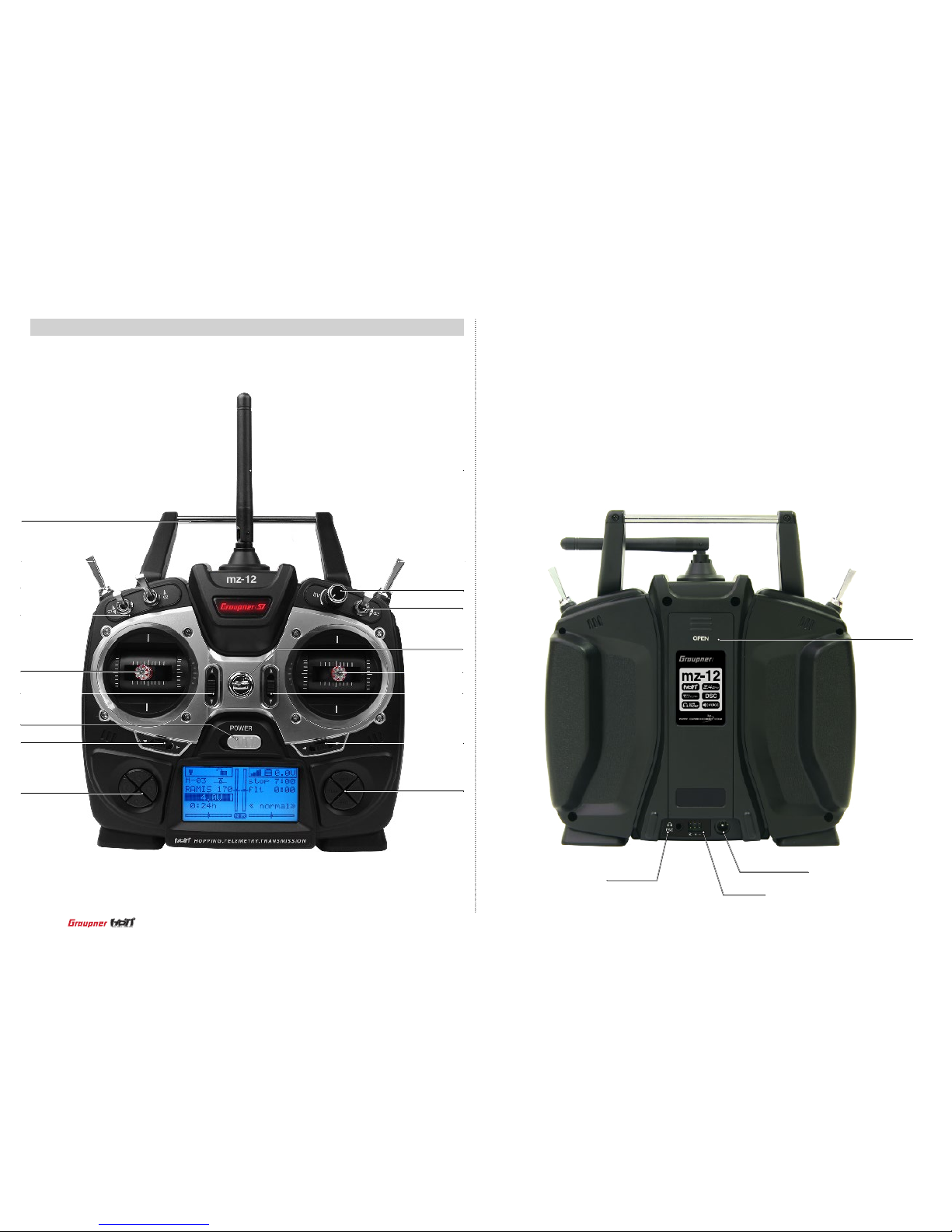
4. TRANSMITTER CONTROL IDENTIFICATION
4
BATTERY COVER
EAR PHONE
DATA PIN
CHARGE SOCKET
TX HANDEL
THRO TRIM
NECKSTRAP LUG
S4 SWITCH
S2 SWITCH
S1 SWITCH
POWER
SWITCH
ELEV/TRIM
RUDD TRIM
ANTENNA
RF TRAINER SWITCH
DIAL VOLUME
S3 SWITCH
THRO/AILE STICK
AILE TRIM
ENT, ESC, TEL
VIEW BUTTON
ELEV/RUDO
STICK
DIRECTION
BUTTON
Page 5
5. SPECIFICATION 7. ADJUSTABLE STICK LENGTH
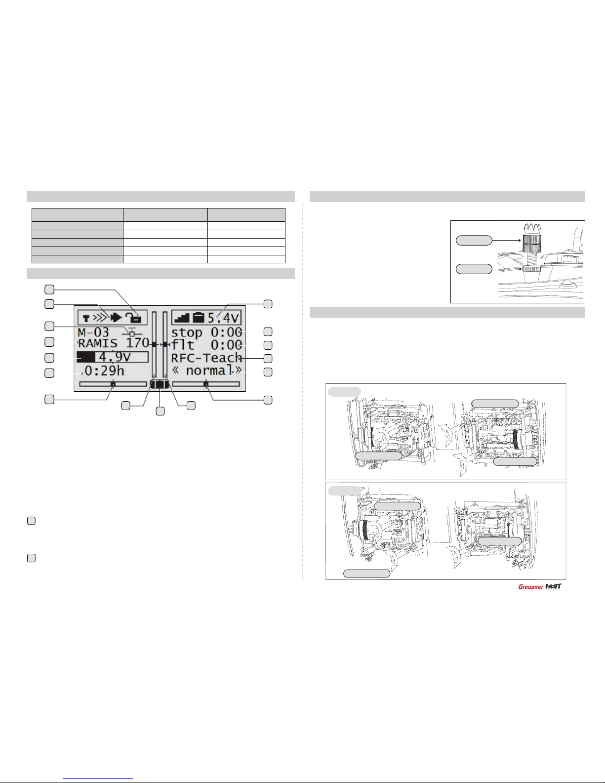
6. DISPLAY EXPLANATION
- Function Help
8. ADJUSTABLE STICK TENSION
The control stick is consisted of 2pc of stick levers and it allows you to adjust the control
stick’s length as you want.
1. Receiver signal indicator
2. Button Lock status
3. Battery voltage of receiver
4. Timer
5. Flight timer
6. Trainer indicator
7. Q. LINK
8. Aileron trim
9. Throttle trim
10. Transmitter type
11. Elevator trim
12. Rudder trim
13. Model type
14. Battery voltage of transmitter
15. Model name and model memory
16. Model type
1. Hold the lever “B” and turn the lever “A”
counter clockwise. Lever “B” The lock will be
released.
2. Turn the lever “B” and adjust the control
stick’s length as you want. Turn the lever
“A” clockwise, then the lever “A” and “B” are
interlocked and fixed.
The mz-12 offers adjustable tension on the throttle, aileron, elevator and rudder sticks.
1. Remove the battery cover and battery form the transmitter
2. Unscrew the six Philips head screws that hold the transmitter’s rear cover and remove the rear
case.
3. Using a Philips screw driver, adjust the stick tension screw for the desired control.
Clockwise to tighten and counter clockwise to loosen.
Button Lock function
This function is used to prevent from pressing buttons accidently during flight.
Press both of TLM and VIEW buttons at the same time to lock the buttons. If you press
both of TLM and VIEW buttons at the same time again, the lock function is turned off.
Transmitter type
- NR (Normal) : When transmitter is operated in the normal mode
- T.T ( Trainer) : When transmitter is operated in the trainer mode
If Jack select programming is set to DSC at Basic sett, there is no display
Frequency band
Modulation
Output power
Current drain
Operating voltage
Transmitter mz-12
Receiver 8 Ch
2.4~2.4835GHz
FHSS
100mW
Approx 125mA
3.4V~6V
2.4~2.4835GHz
FHSS
-
Approx 70mA
3.6V~8.4V
5
16
15
14
13
12
3
4
5
6
7
8
911
10
1
2
Leve r “A”
Lever “B”
Aileron tension
Rudder tension
Elevator tension
Elevator tension
Rudder tension
Aileron tension
Model 2
Model 1
10
2
Page 6
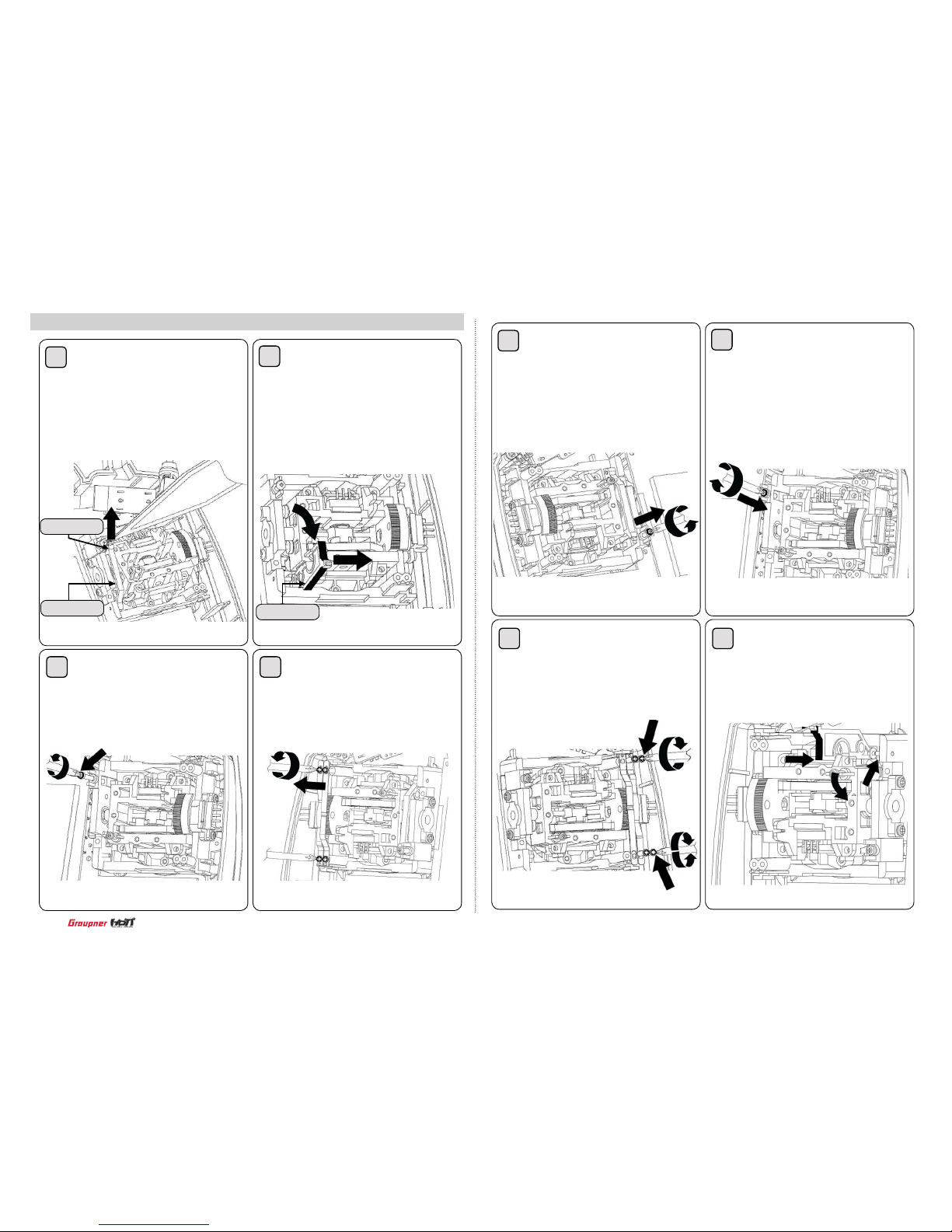
9. Mode exchange of throttle stick for Mode 1 and Mode 2
Unscrew the transmitter’s rear case
and remove the rear case and disas
-
semble the tension spring from the
centering cam in the elevator gimbal
of mode 1 transmitter with tweezers
Unscrew the tension spring control
bolt in the elevator gimbal of mode 1
transmitter
Disassemble the centering cam
form the gimbal
Disassemble 2pcs of leaf spring
in the throttle gimbal of mode 1
transmitter
Tension spring
Centering cam
Centering cam
1
3
2
4
5
7
6
8
Unscrew the tension spring control
bolt in the elevator gimbal of mode
1 transmitter
Assemble 2pcs of disassembled leaf
spring from the throttle gimbal of
mode 1 transmitter into the elevator
gimbal and adjust the bolt for the
desired control
Screw the disassembled bolt from
the throttle gimbal of mode 1 trans
-
mitter into the elevator gimbal to x
the controller
Assemble the disassembled
centering cam form the elevator
gimbal of mode 1 transmitter into
the throttle gimbal pin
6
Page 7

Assemble the transmitter’s rear case and switch to mode 2 from mode 1 at Stick mode page
in the transmitter programming setup section according to the manual.
Ratchet Type Options and Strength Adjustment for Throttle Stick.
There are two options for the ratchet type of throttle stick. The one is clank type generally operat
-
ing airplane and the other one is no-clank type usually operating helicopter.
The right sided screw of the black-colored circles on the below picture is for strength adjustment
of throttle ratchet spring in case of operating helicopter (no-clank type).
The left sided screw of the black-colored circles on the below picture is for strength adjustment
of throttle ratchet spring in case of operating airplane (clank type).
Therefore, you can pick your required type by tightening the related screw (left screw for air
-
plane; right screw for helicopter).
Please refer to the below picture, you can adjust the screw.
The sticks of mz-12 Europe Version shall be operated by tension Modes.
According to the below picture with guideline, after disabling the other side stick, you can pick
the throttle channel of mode 1 or 2.
The method of Disabling Tension
The both sticks could be used tension or throttle types according to the users.
At rst, you can open the case of Transmitter.
If you turn the screw clockwise at the blow black-colored circle, the tension function shall be
disabled.
If you want to use the one stick by throttle function, you can disable the tension of the stick.
Please refer to the below picture, you can adjust the screw.
9
10
Assemble the centering cam into the
throttle gimbal of mode 1 transmitter
and set the spring in the center
control part and the centering cam
with tweezers
Screw the disassembled tension
control bolt from the elevator gimbal
of mode 1 transmitter into the throttle
gimbal and adjust the bolt for the
desired control
Tension spring
7
Make sure to test all functions are normally operated in mode 2 before ying
NOTICE
Page 8
10. WHAT IS HoTT
11. BATTERY INSTALLATION
HOPPING TELEMETRY TRANSMISSION(HoTT)
it is Graupner’s unique telemetry technology in 2.4GHz signal protocol that support Bi directional data transmission gives user real-time information on things like user model’s RPM, Voltage,
Temperature, User programmed warning, and etc. The use of up to 75 channels ensures extreme operating reliability and immunity to external interference thanks to optimized frequency
hopping broad channel sequence.
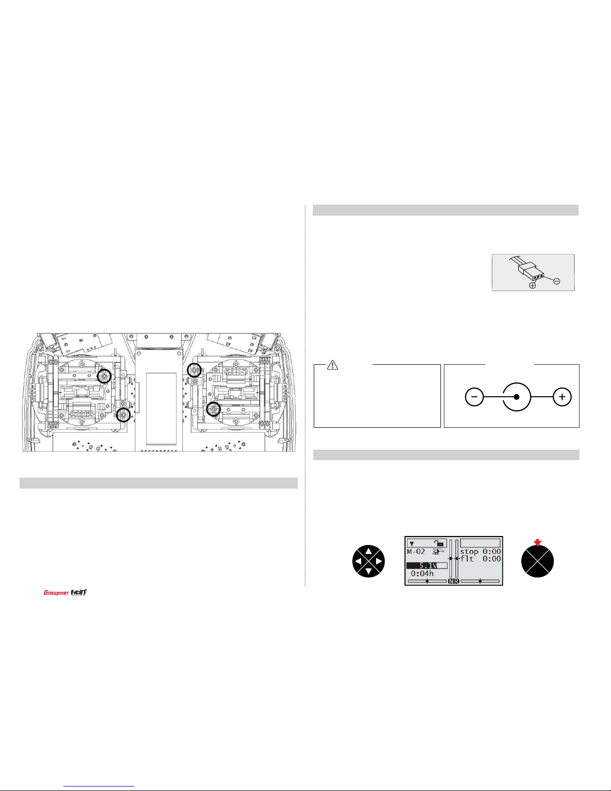
Optional NiCd or NiMH 1.2-volt AA rechargeable 4-cell batteries can be used. A battery connecter is on the inside of the transmitter for convenient recharging. Graupner offers rechargeable NiCd, NiMH batteries, part number S22331.
Remove the battery cover and install the battery pack
ensuring the polarity of the battery connecter.
The included charger is designed to recharge your batteries at a rate of 150mA. Do not use
this charger for equipment other than Graupner transmitters that use 4-cell battery packs.
The charging plug polarity may not be the same and equipment damage can result. During
the charging operation, the charger’s temperature is slightly elevated. This is normal.
The mz-12 is compatible with all current Graupner Aircraft receivers ( R Series )
• CHARGING BATTERIES
Charge only rechargeable batteries.
Non-rechargeable batteries may burst
causing injury to persons and/or damage to property. Never leave charging
batteries unattended.
Graupner
Transmitter Charge Jack Polarity
CAUTION
The Spring Strength Adjustment of Elevator, Aileron and Rudder Stick.
According to your preference, you can adjust the spring tension by tightening the related screws
for elevator, aileron and rudder stick.
There are related screws beside return-spring as below picture.
You can tighten the related screws for tension its adjustment (elevator, aileron and rudder).
There are the screws at the black-colored circles. You can tighten the screw for stronger and
loosen for smoothly.
Please refer to the below picture, you can adjust the screw.
12.
BINDING
1. With the transmitter on and the home screen displayed, press the ENT button.
You must bind the receiver to the transmitter before the receiver will operate. Binding
teaches the receiver the specific code of the transmitter so that it will only connect to
it’s corresponding transmitter.
ENT
ESC
TEL VIW
press
8
Page 9
ENT
ESC
TEL VIW
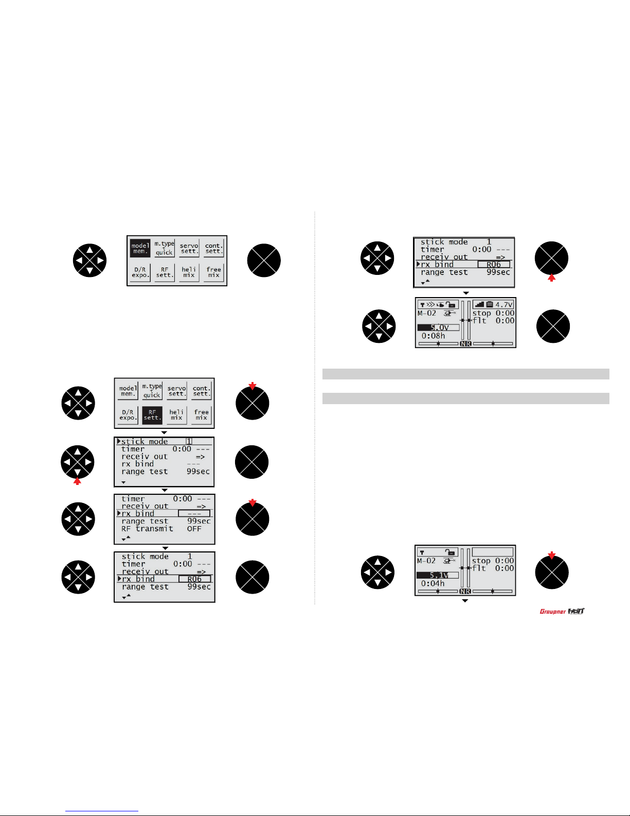
2. The model men is highlighted then press the direction button to highlight RF sett.
4. After completing the bind, press the ESC button to return to the home screen.
3. Press the ENT button, the cursor is automatically on the stick mode line then press the
direction button to select the hyphen in the rx bind line. Turn on the receiver then press the
ENT button on the receiver for over 3 seconds so that the receiver enter the binding mode.
Press the ENT button of the transmitter, the system will be connected within a few seconds
and the model name of the receiver is displayed on the screen.
ENT
ESC
TEL VIW
ENT
ESC
TEL VIW
ENT
ESC
TEL VIW
ENT
ESC
TEL VIW
ENT
ESC
TEL VIW
ENT
ESC
TEL VIW
press
press
press
press
1. Model mem (Aircraft and Helicopter)
The model mem (model memory) contains 4 categories: select model, model name, clear
model and copy model.
•
Select model : It is used to add or select model of the already set 10 models.
•
Model name : The Model Name function allows you to name a model. This makes identify-
ing and selecting models much easier.
•
Clear model : Clear Model is used to remove the programmed model you will no longer be
ying. No other model memories will be affected.
•
Copy mod->mod : Copy model function copies the currently selected model’s programmed
value to another model list.
•
The Transmitter Programming Setup
ENT
ESC
TEL VIW
press
9
Page 10
- Select model
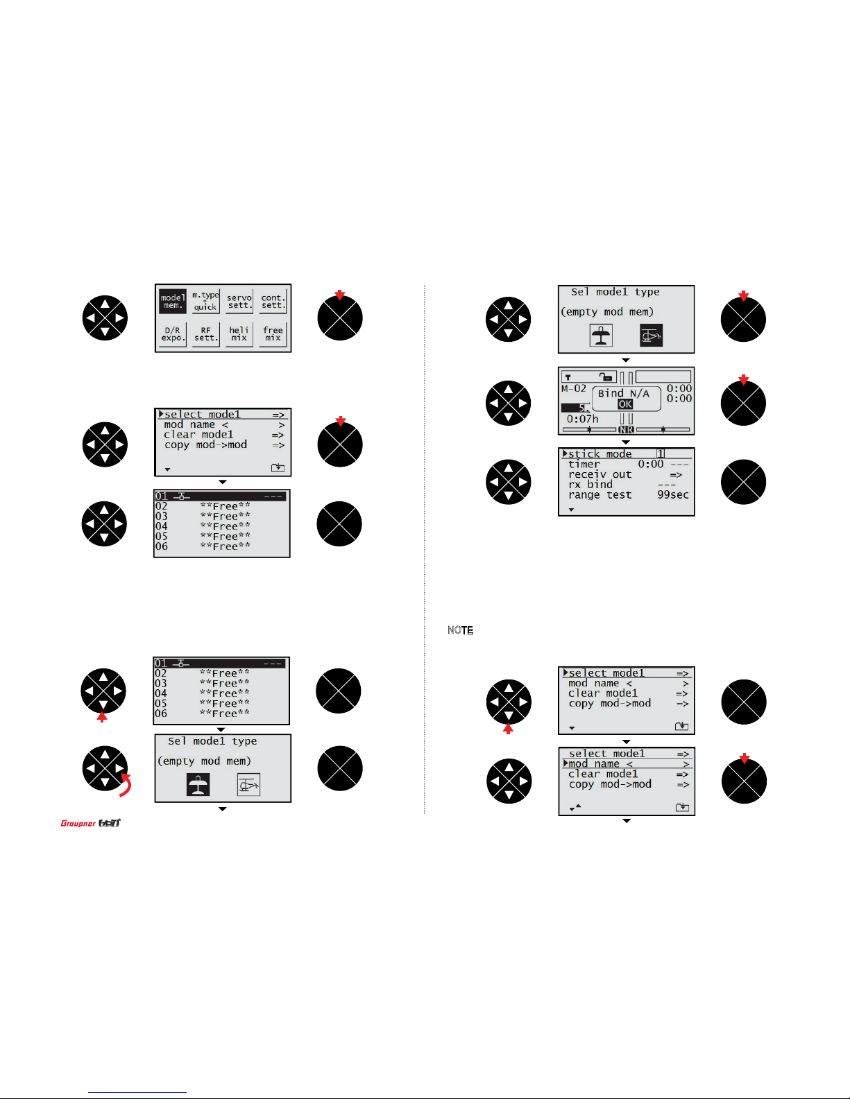
In the home screen, press the ENT button then the model mem is highlighted. Press the ENT
button to access the function.
Press the direction button to select the model then press the ENT button to access the Sel
model type screen. Press the direction button to highlight the desired model type (Aircraft
or Helicopter) then press the ENT button to select the model type. The home screen is
displayed and the popup message “Bind N/A with the highlight on OK” appears then press
the ENT button to bind. The rx bind screen automatically appears then you may bind the
transmitter to the receiver according to the bind procedure.
ENT
ESC
TEL VIW
ENT
ESC
TEL VIW
ENT
ESC
TEL VIW
ENT
ESC
TEL VIW
ENT
ESC
TEL VIW
ENT
ESC
TEL VIW
ENT
ESC
TEL VIW
ENT
ESC
TEL VIW
press
press
press
press
press
press
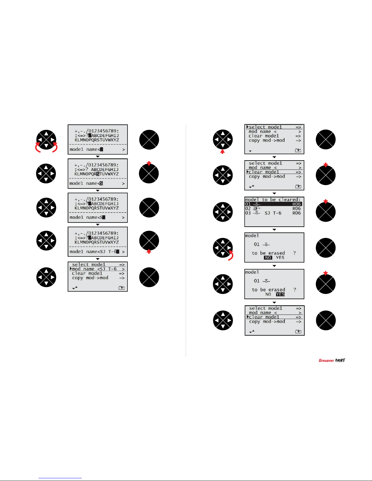
- Model name
When the model mem is highlighted, press the ENT button then the cursor is on the
select model line. Press the direction button to select the mod name line then press the
ENT button to access to the function. Press the direction button to highlight the desired
character then press the ENT button to accept. Repeat the process until completing. The
name will display on the model name line. Press the ESC button to get back to the model
mem screen.
NOTE : Pressing the direction button to highlight the blank and pressing the ENT button
will erase the current character.
ENT
ESC
TEL VIW
press
ENT
ESC
TEL VIW
press
10
Page 11
VIW
VIW
ENT
ESC
TEL VIW
ENT
ESC
TEL VIW
ENT
ESC
TEL VIW
ENT
ESC
TEL VIW
ENT
ESC
TEL VIW
press
press
press
- Clear model
When the model mem is highlighted, press the ENT button then the cursor is on the select model line. Press the direction button to select the clear model line then press the ENT
button to access to the function. Press the direction button to highlight the model that you
wish to clear then press the ENT button. The popup message “YES or NO” appears on
the screen. Press the direction button to highlight YES then press the ENT button to clear
the model. The screen will return to the model mem screen.
ENT
ENT
ESC
TEL VIW
ENT
ESC
TEL VIW
press
press
ENT
ESC
TEL VIW
ENT
ESC
TEL VIW
ENT
ESC
TEL VIW
ENT
ESC
TEL VIW
press
press
press
11
Page 12
2. m.type + quick (Aircraft)
The m.type+quick function allows to program the various function of Airplane and Helicopter
model. Always choose model type (Aircraft or Helicopter) before programming any other
function of the selected model type. The function that can be programmed is different
depends on the model type, Aircraft or Helicopter.
•
Motor at C1 : Use the motor at C1 function to set the direction of the throttle channel in the
Aircraft and program to use the throttle channel as the brake in the glider.
•
Tail type : Use the Tail type functions to program the tail mix to match your airplane.
4 tail types (normal, V tail, delt/w, 2elev sv appear) are available.
•
Aile/ap : Use the Aile/ap functions to program aile/ap mix to match your airplane 5 aile/
aps (1aile, 1aile 1ap, 2aile, 2aile 1ap, 2aile 2ap) are available.
ENT
ESC
TEL VIW
ENT
ESC
TEL VIW
ENT
ESC
TEL VIW
ENT
ESC
TEL VIW
ENT
ESC
TEL VIW
ENT
ESC
TEL VIW
ENT
ESC
TEL VIW
ENT
ESC
TEL VIW
ENT
ESC
TEL VIW
press
press
press
press
press
press
press
press
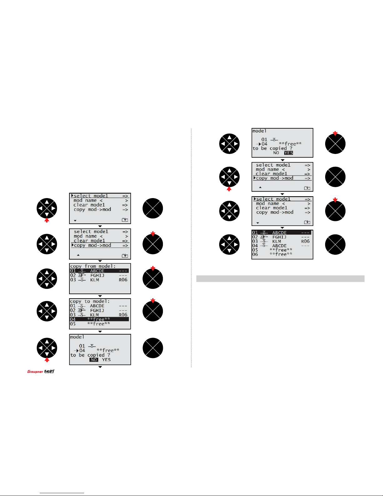
- Copy mod->mod
The model mem is highlighted in the menu screen then press the ENT button. The cursor is
on the select model line. Press the direction button to select the copy mod ->mod line then
press the ENT button to access to the function. When the copy from model screen appears,
press the direction button to highlight the model you want to copy then press the ENT button
to accept. When the copy to model screen appears, press the direction button to highlight the
model memory to copy to then press the ENT button to accept. The message “to be copied
YES or NO” appears on the screen. Press the direction button to highlight YES then press the
ENT button to complete to copy. The copy mod ->mod is automatically displayed. If you press
the ENT button after selecting the select model line then you may check the copied model.
12
Page 13
• Quick link set : The quick link sett function allows to adjust the D/R expo value and to assign
the corresponding switch to cope with various ight conditions such as 3D ight or the ight
with the strong wind. Since the adjusted value is activated by moving the switch, you can
cope with various ight conditions with switch. It makes you operating the ight much easier.
You can select take off, thermal, dist, speed, acro, landing, air-tor, test at quick2 and quick3.
•
Quick link trim : Use the quick link trim function to program the appropriate trims of the
quick 2 and quick 3 in the quick link. The user can program the trim in advance to cope with
various ight condition such as 3D ight or the ight with the strong wind and match the ight
situation of the takeoff , thermal and speed of the glider. If the switch is ON, the corresponding trim is activated so the user does not need to set these trims every time.
NOTICE : The programming value of the quick link trim depends on the motor at C1, Tail type,
Aile/ap
ENT
ESC
TEL VIW
ENT
ESC
TEL VIW
ENT
ESC
TEL VIW
ENT
ESC
TEL VIW
ENT
ESC
TEL VIW
ENT
ESC
TEL VIW
press
press
press
press
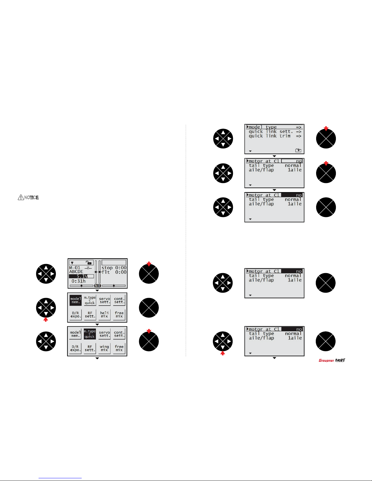
With the transmitter and the home screen displayed, press the ENT button. Press the direction button to highlight the m.type quick then press the ENT button to access. The model
type is selected then press the ENT button to select the motor at C1. Press the ENT button
again to highlight the value in the motor at C1 then press the direction button to select the
desired value. 4 values ( no, no/inv , idel re, idel fr) as explained below are available.
press
- Motor at C1 no
It creates the air brakes using aile/ap. When the C1 (The throttle channel) is moved, 1~3
air brakes that the user programmed is created. The value of the created air brake would be
programmed, the air brake function works according to the throttle stick’s movement from the
high to the lower position. When the throttle stick moves to the high position, the air brake
channel is in the neutral, when it moves to low position, the air brake works proportionately to
the throttle stick’s movement according to the programming.
ENT
ESC
TEL VIW
- Motor at C1 no/inv
It is contrary to ”no”. When the throttle stick moves to the low position, the air brake channel is
in the neutral, when it moves to high position, the air brake works proportionately to the throttle
stick’s movement according to the programming.
ENT
ESC
TEL VIW
press
13
Page 14
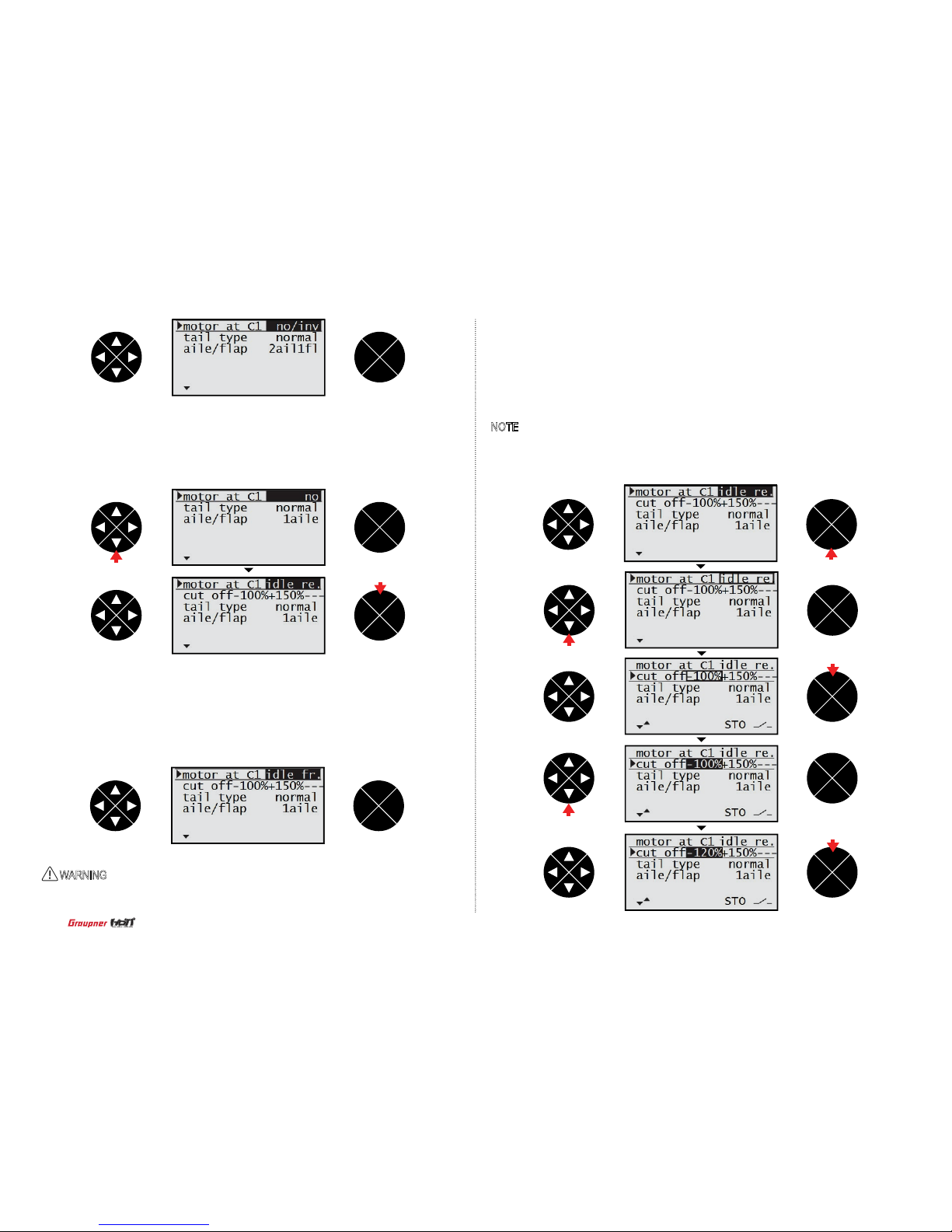
- Motor at C1 idel re
The idle position of the throttle stick (C1) is back, toward the user, if the throttle stick is not there,
the throttle warning message “Throttle too high” appears and the cut off option is activated.
- Motor at C1 idel fr
The idle position of the throttle stick (C1) is forward, away from the user, if the throttle
stick is not there, the throttle warning message “Throttle too high” appears and the cut off
option is activated.
- Cut off
When the option of “idle re” or “idle fr” is selected, the cut off option is activated. It turns off
the internal combustion engine or the electric motor.
Press the ENT button to remove the highlight of the motor at C1 value then press the
direction button to select the cut off line. Press the ENT button to highlight -100% of the cut
off value then press the direction button to adjust the value. Press the ENT button to remove
the highlight
NOTE : The value of -100% is the cut off position the user can program, if the cut of f value is
programmed less than -100%, the breathing hole of Engine carburetor is block or the speed
controller make the motor off so the power is not delivered to the airplane.
ENT
ESC
TEL VIW
ENT
ESC
TEL VIW
ENT
ESC
TEL VIW
ENT
ESC
TEL VIW
ENT
ESC
TEL VIW
ENT
ESC
TEL VIW
ENT
ESC
TEL VIW
ENT
ESC
TEL VIW
press
1 time press
ENT
ESC
TEL VIW
press
WARNING : Ensure that any internal-combustion engine or electric motor shouldn’t be
running accidentally during the programming process.
press
press
press
press
14
Page 15
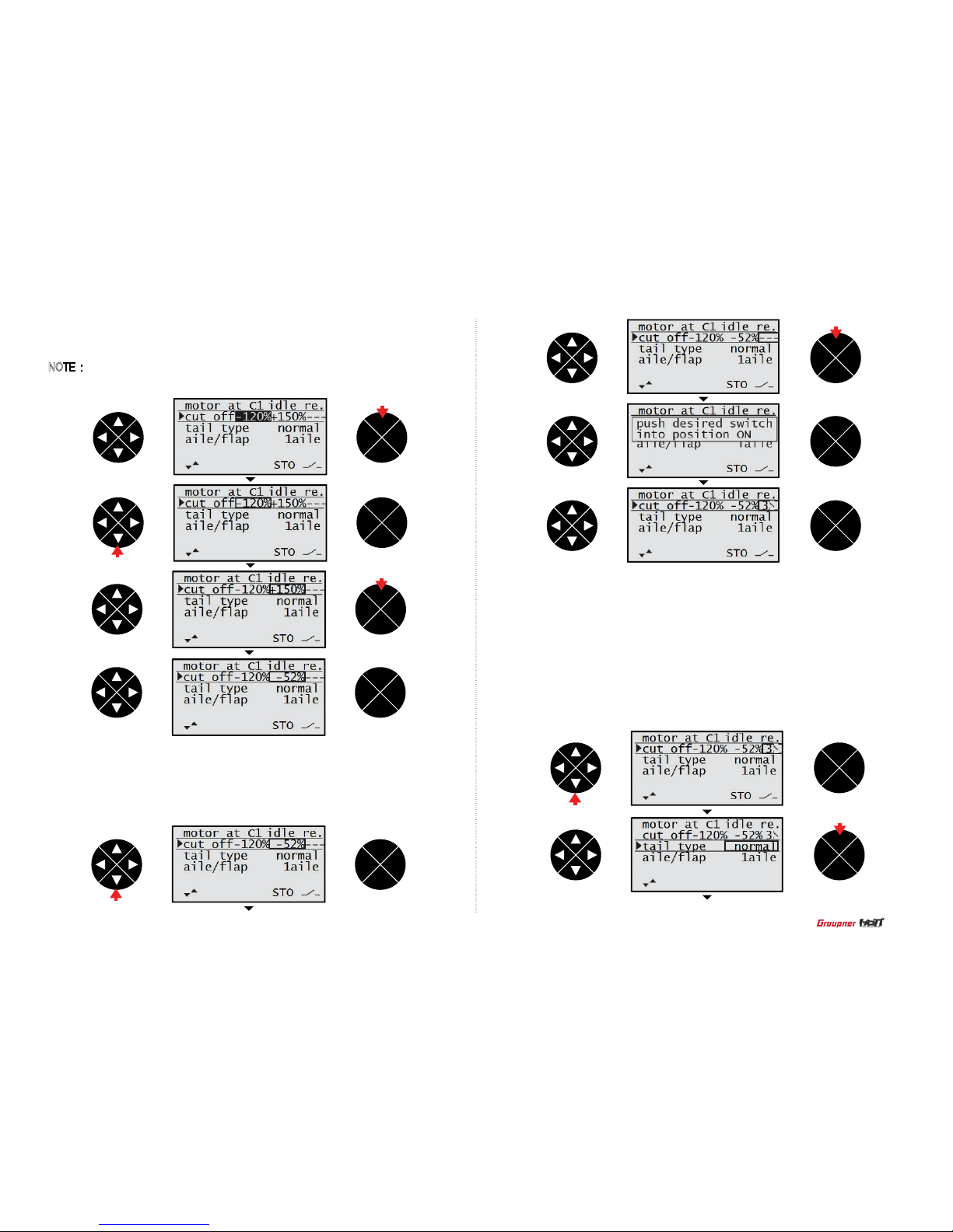
Press the direction button to select the value,+150%,. Place the throttle stick at the desired
position and press the ENT button then the adjusted value is applied (The adjusted value is
activated when the throttle stick is in that position).
NOTE : the value,+150%, is the throttle stick position where the cut off function is activated.
Press the direction button to select the hyphen then press the ENT button. The popup
message “push desired switch into position on” appears then move the switch to the desired
position (The cut off function is activated when the switch is moved to that position)
ENT
ESC
TEL VIW
ENT
ESC
TEL VIW
ENT
ESC
TEL VIW
ENT
ESC
TEL VIW
press
press
ENT
ESC
TEL VIW
press
press
ENT
ESC
TEL VIW
ENT
ESC
TEL VIW
ENT
ESC
TEL VIW
press
- Tail type
Use the Tail type functions to program the tail mix to match your airplane. 4 tail types (normal,
V tail, delt/w, 2elev sv appear) are available. The correct value should be matched each other
since the some value is not match to the others, refer to the below table.
Press the direction button to select the tail type line then press the ENT button to highlight the
value. Press the direction button to choose desired value then press the ESC button to remove
the highlight. Press the ESC button again to return to the previous screen.
ENT
ENT
ESC
TEL VIW
ENT
ESC
TEL VIW
press
press
15
Page 16
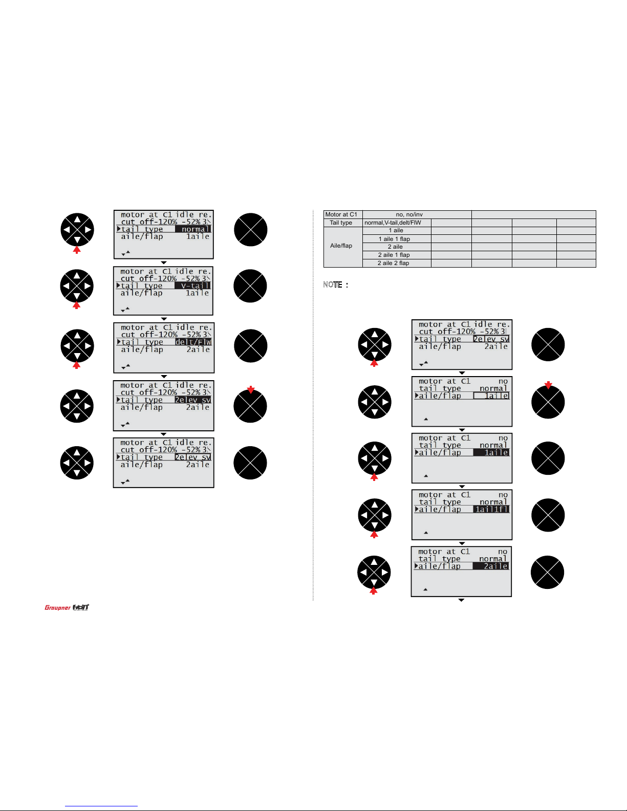
- Aile/ap
Use the Aile/ap functions to program aile/ap mix to match your airplane. 5 aile/aps (1aile,
1aile 1ap, 2aile, 2aile 1ap, 2aile 2ap) are available. The correct value should be matched
each other since the some value is not match to the others, refer to the below table. Press the
direction button to select the aile/ap line then press the ENT button to highlight the value. Press
the direction button to choose desired value then press the ESC button to remove the highlight.
Press the ESC button again to return to the previous screen.
NOTE : The correct value should be matched each other since the some value is not
match to the others, refer to the table.
ENT
ESC
TEL VIW
ENT
ESC
TEL VIW
ENT
ESC
TEL VIW
ENT
ESC
TEL VIW
ENT
ESC
TEL VIW
ENT
ESC
TEL VIW
ENT
ESC
TEL VIW
ENT
ESC
TEL VIW
ENT
ESC
TEL VIW
ENT
ESC
TEL VIW
press
press
Motor at C1
Tail type
Aile/ap
no, no/inv
1 aile 1 ap
normal,V-tail,delt/FlW
2 aile
1 aile
2 aile 1 ap
2 aile 2 ap
1 aile 1 ap
2 elev sv
2 aile
1 aile
2 aile 1 ap
1 aile 1 ap
normal,V-tail
Idle re, idel fr
2 aile
1 aile
2 aile 1 ap
2 aile 1 ap
2 aile 2 ap
Delt/FlW
2 aile
1 aile 1 ap
2 elev sv
2 aile
1aile
press
press
press
press
press
press
press
16
Page 17
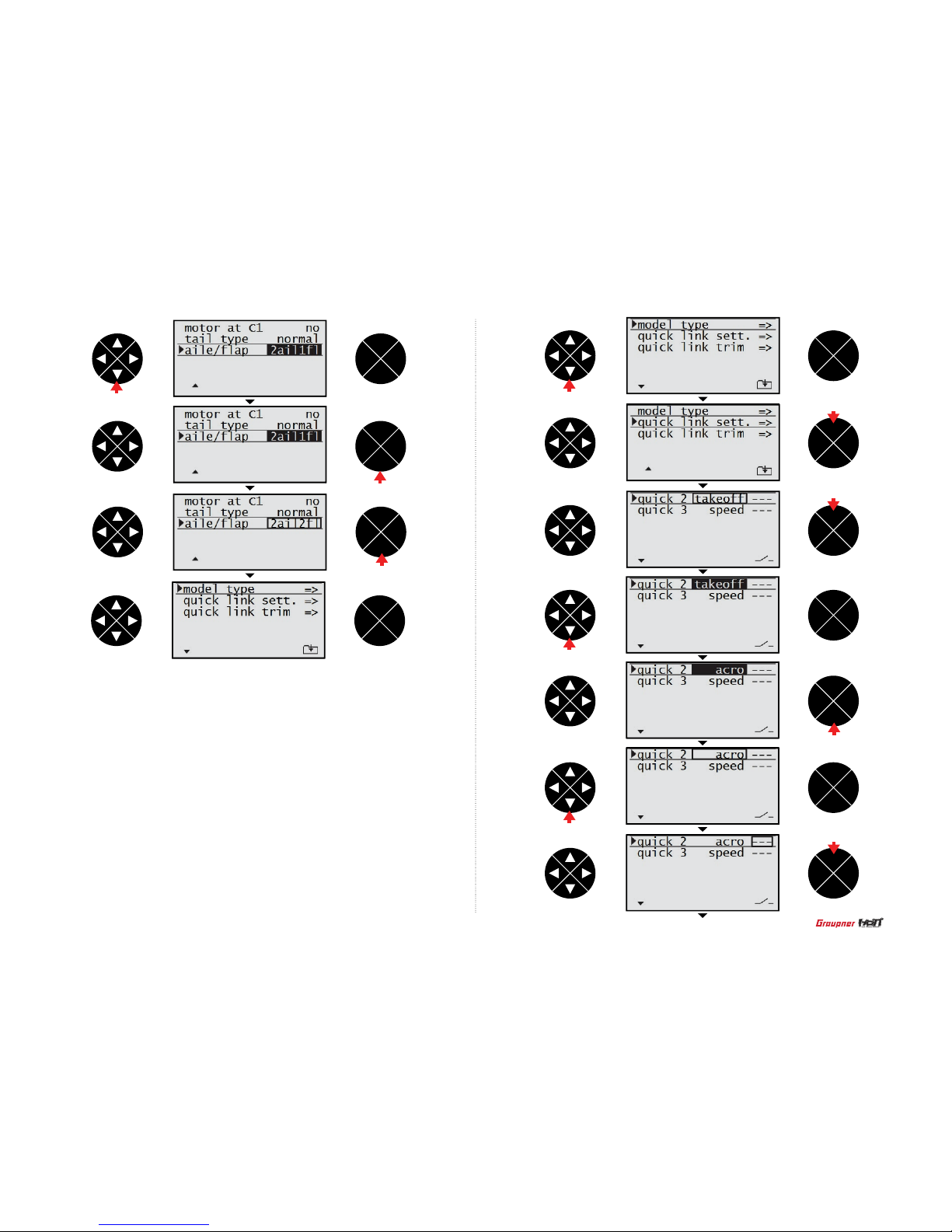
- Quick link sett
The quick link sett function allows to adjust the D/R expo value and to assign the corresponding switch to cope with various ight conditions such as 3D ight or the ight with the
strong wind. Since the adjusted value is activated by moving the switch, you can cope with
various ight conditions with switch. It makes you operating the ight much easier.
You can select take off, thermal, dist, speed, acro, landing, air-tor, test at quick2 and
quick3.
Press the direction button to select the quick link sett then press the ENT button to access
the function. Press the direction button to select the qucik2 line or the quick3 line then
press the ENT button to highlight the value. Press the direction button to select the desired
value (take off, thermal, dist, speed, acro, landing, air-tor, test at quick2 and quick3). Press
the ENT button to remove the highlight then press the direction button to select the hyphen.
If you press the ENT button, the popup message “push desired switch into position on”
appears. Move the switch to the desired position then the corresponding value appears.
Press the ESC button to get back to the m.type + quick screen then the quick link programming is completed.
ENT
ESC
TEL VIW
ENT
ESC
TEL VIW
ENT
ESC
TEL VIW
ENT
ESC
TEL VIW
ENT
ESC
TEL VIW
ENT
ESC
TEL VIW
ENT
ESC
TEL VIW
press
press
press
press
press
press
ENT
ESC
TEL VIW
ENT
ESC
TEL VIW
ENT
ESC
TEL VIW
1 time press
press
press
ENT
ESC
TEL VIW
press
17
Page 18
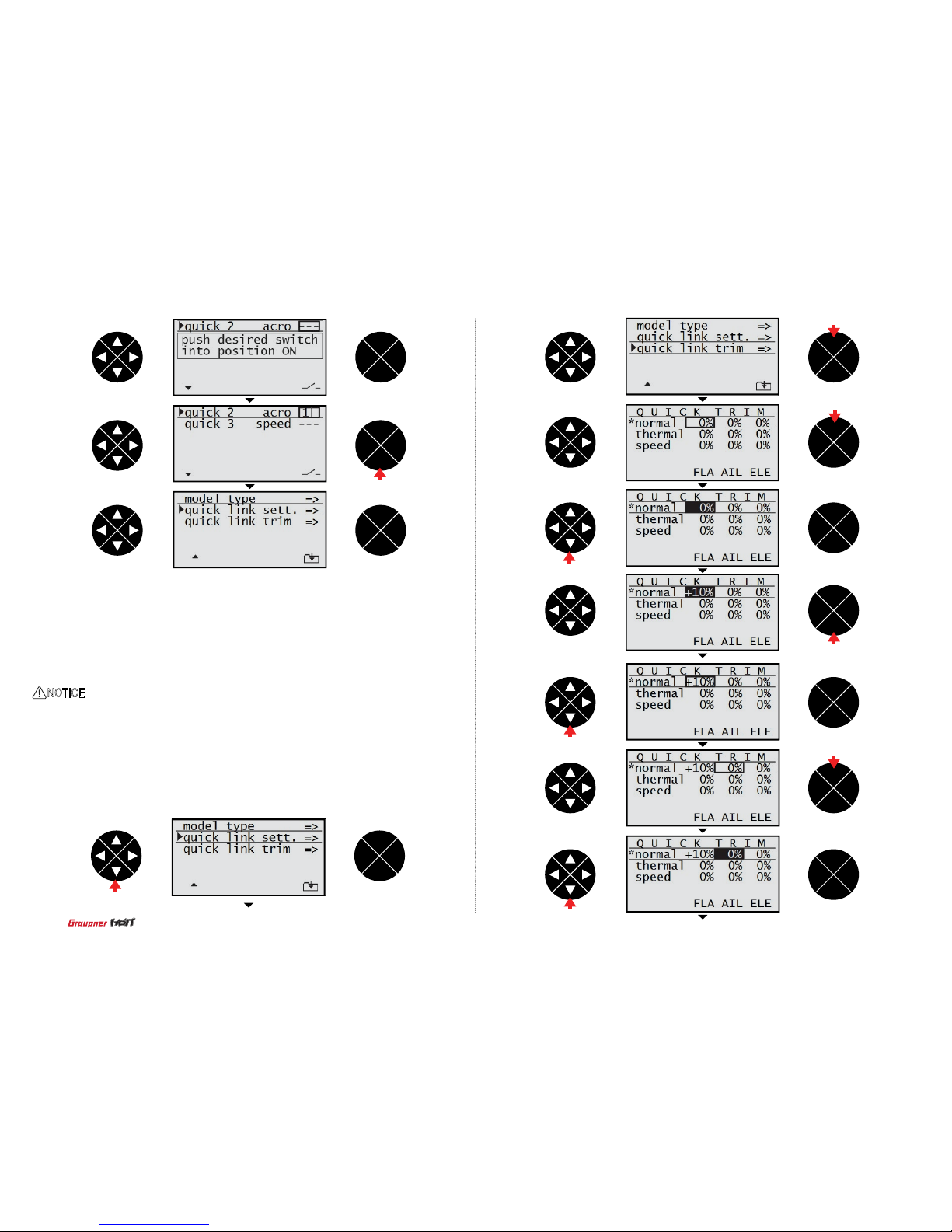
- Quick link trim
Use the quick link trim function to program the appropriate trims of the quick 2 and quick 3 in the
quick link. The user can program the trim in advance to cope with the unexpected situation such
as the ight with the strong wind and match the ight situation of the takeoff , thermal and speed
of the glider. If the switch is ON, the corresponding trim is activated so the user do not need to
set these trims every time.
Here is an example in case of motor at C1 (no) , tail type (normal) , aile/ap (2aile 2ap) at the
model type Press the ENT button to access the function. The cursor is on the FLA value in the
normal line then press the ENT and the direction buttons to highlight and adjust the desired
value. Press ENT button and direction button to remove the highlight and select the AIL value.
The AIL value and ELE value can be adjusted in the same method with the FLA programming.
ENT
ESC
TEL VIW
ENT
ESC
TEL VIW
ENT
ESC
TEL VIW
ENT
ESC
TEL VIW
ENT
ESC
TEL VIW
ENT
ESC
TEL VIW
ENT
ESC
TEL VIW
ENT
ESC
TEL VIW
ENT
ESC
TEL VIW
ENT
ESC
TEL VIW
ENT
ESC
TEL VIW
press
press
press
NOTICE: The programming value of the quick link trim depends on the motor at C1, Tail type,
Aile/ap
press
press
press
press
press
press
18
Page 19
- thermal quick link의 의의의의 ON의의 의의의의 normal의의 thermal의 의의의의 ON 의의 의의의 의의의
의의.
- thermal quick link의 의의의의 ON의의 의의의의 normal의의 thermal의 의의의의 ON 의의 의의의 의의의
의의.
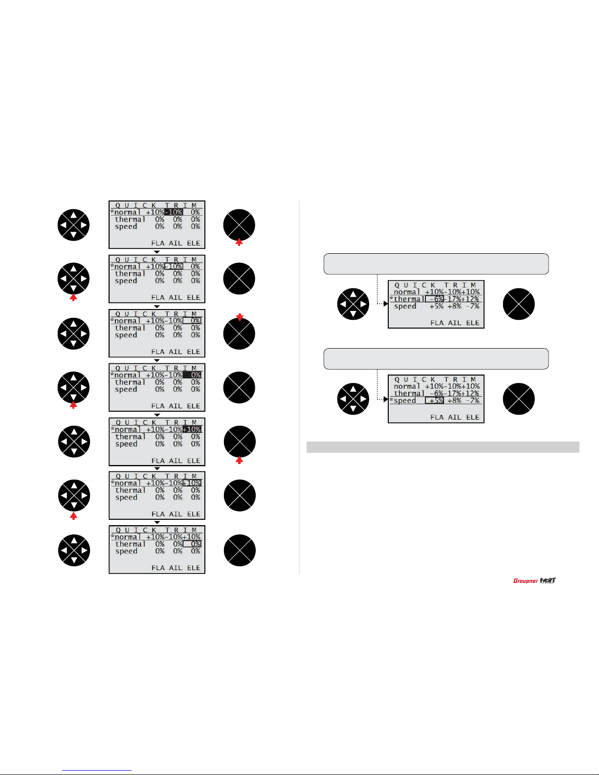
After completing the normal quick link adjustment, press the direction button to select the
thermal quick link line. The thermal quick link and speed quick link can be programmed in
the same method. If you already set the quick link switch and the switch is ON, the cursor is
automatically moved to the corresponding quick link value.
If the thermal quick link switch is ON, the cursor is moved to the
thermal quick link and the user can check the thermal quick link is ON
If the speed quick link switch is ON, the cursor is moved to the speed
quick link and the user can check the speed quick link is ON
ENT
ESC
TEL VIW
ENT
ESC
TEL VIW
ENT
ESC
TEL VIW
ENT
ESC
TEL VIW
ENT
ESC
TEL VIW
ENT
ESC
TEL VIW
ENT
ESC
TEL VIW
ENT
ESC
TEL VIW
ENT
ESC
TEL VIW
press
press
press
press
press
press
2-1. Model type (Helicopter) : 5 functions are available
• Swashplate
Use the swashplate function to set the swahplate type to match your Helicopter model.
It supports 6 value (1servo, 2 servo,3sv(2rol),3sv(140),3sv(2nic),4sv(90))
• Cut off
The cut off function allows to turn off the internal combustion engine or the electric motor.
• Rotor direct
Use the rotor direct function to set the rotation direction of the main rotor.
• Pitch min
Use the pitch min function to reverse the servo direction in all of pitch, elevator, aileron and
throttle
channels, the default value is rear. Available settings are rear and front.
19
Page 20
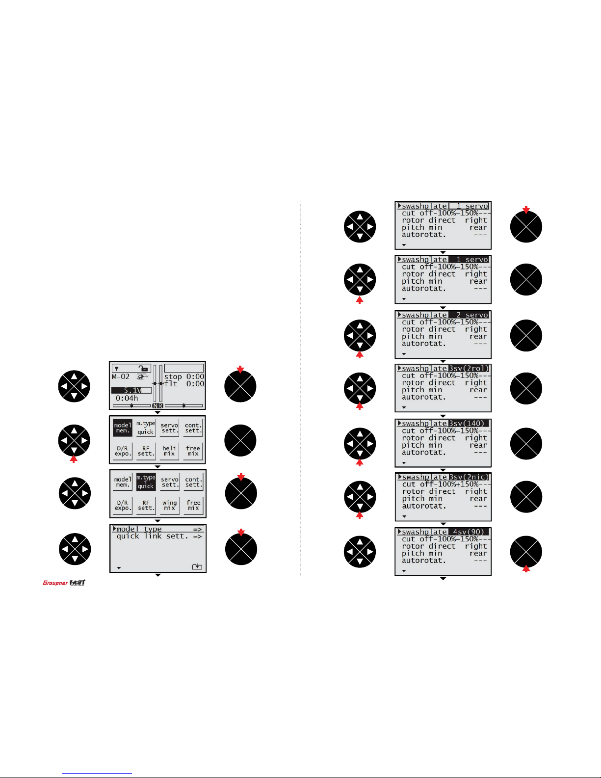
- Swash plate
With the transmitter on and the home screen displayed, press the ENT button. The transmitter
menu is displayed. Press the direction button to move the highlight to the m.type quick then press
the ENT button to access the m.type quick function. The cursor is on the model type line then
press the ENT button to highlight the value. Press the direction button to the desired value in the
swashplate line then press the ESC button to remove the highlight
ENT
ESC
TEL VIW
ENT
ESC
TEL VIW
ENT
ESC
TEL VIW
ENT
ESC
TEL VIW
ENT
ESC
TEL VIW
ENT
ESC
TEL VIW
ENT
ESC
TEL VIW
ENT
ESC
TEL VIW
ENT
ESC
TEL VIW
ENT
ESC
TEL VIW
ENT
ESC
TEL VIW
press
press
press
press
press
press
press
press
press
press
press
• Aurtorotat
You may set the switch to be used as auto rotation. If the switch is on, throttle channel is hold
at 90% position and pitch, elevator and aileron that is connected to throttle channel are normal
operated. It is the same function with throttle hold.
• Quick link sett
The quick link sett function allows to adjust the quick2 value and assign the corresponding switch
to cope with various ight conditions such as 3D ight or the ight with the strong wind.
Since the adjusted value is activated by moving the switch, you can cope with various ight conditions with switch. It makes you operating the ight much easier.
You can select hover, acro, acro 3D, speed and test at the quick2 line.
20
Page 21

- Cut off
Press the direction button to select the cut off line then press the ENT and the direction
button to highlight and adjust the value less than -100%. Press the ESC button to remove
the highlight.
NOTE : The value of -100% is the cut off position the user can program, if the cut off value
is programmed less than -100%, the breathing hole of Engine carburetor is block or the
speed controller lets the motor off so the power is not delivered to the Helicopter.
Press the direction button to select +150% in the value.
Place the throttle stick at the desired position and press the ENT button then adjusted
value is applied (The adjusted value is activated when the throttle stick is in that position).
NOTE : the value of +150% is the throttle stick position where the cut off function is
activated.
Press the direction button to select the hyphen then press the ENT button. The popup
message“push desired switch into position ON”appears then move the switch to the desired
position (The cut off function is activated when the switch is moved to that position)
ENT
ESC
TEL VIW
ENT
ESC
TEL VIW
ENT
ESC
TEL VIW
ENT
ESC
TEL VIW
ENT
ESC
TEL VIW
ENT
ESC
TEL VIW
ENT
ESC
TEL VIW
ENT
ESC
TEL VIW
ENT
ESC
TEL VIW
press
press
ENT
ESC
TEL VIW
ENT
ESC
TEL VIW
press
press
press
press
press
press
21
Page 22
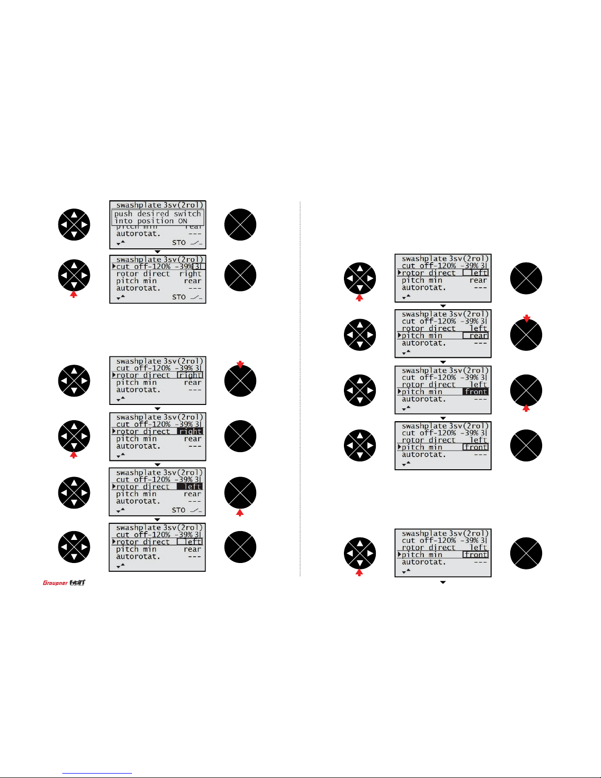
- Rotor direction
Press the direction button to select the rotor direct line then press the ENT button to highlight the
value. Press the direction button to select the right or left. Press the ESC button to remove the
highlight.
- Pitch min
Use the pitch min function to reverse the servo direction in all of pitch, elevator, aileron
and throttle channels, the default value is rear. Available settings are rear and front.
Press the direction button to select the pith min line then press the ENT button to highlight the pitch min value. Press the direction to select the desired value (rear or front)
then press the ESC button to remove the highlight.
- Aurtorotat
Press the direction button to select the autorotat line then press the ENT button. The popup
message “push desired switch into position ON” appears. Move the switch to the desired position then the corresponding value appears. The autorotat function is activated when the switch
is moved to that position. Press the ESC button to get back to the m.type + quick screen.
ENT
ESC
TEL VIW
ENT
ESC
TEL VIW
ENT
ESC
TEL VIW
ENT
ESC
TEL VIW
ENT
ESC
TEL VIW
ENT
ESC
TEL VIW
ENT
ESC
TEL VIW
ENT
ESC
TEL VIW
ENT
ESC
TEL VIW
ENT
ESC
TEL VIW
ENT
ESC
TEL VIW
press
press
press
press
press
press
press
press
22
Page 23
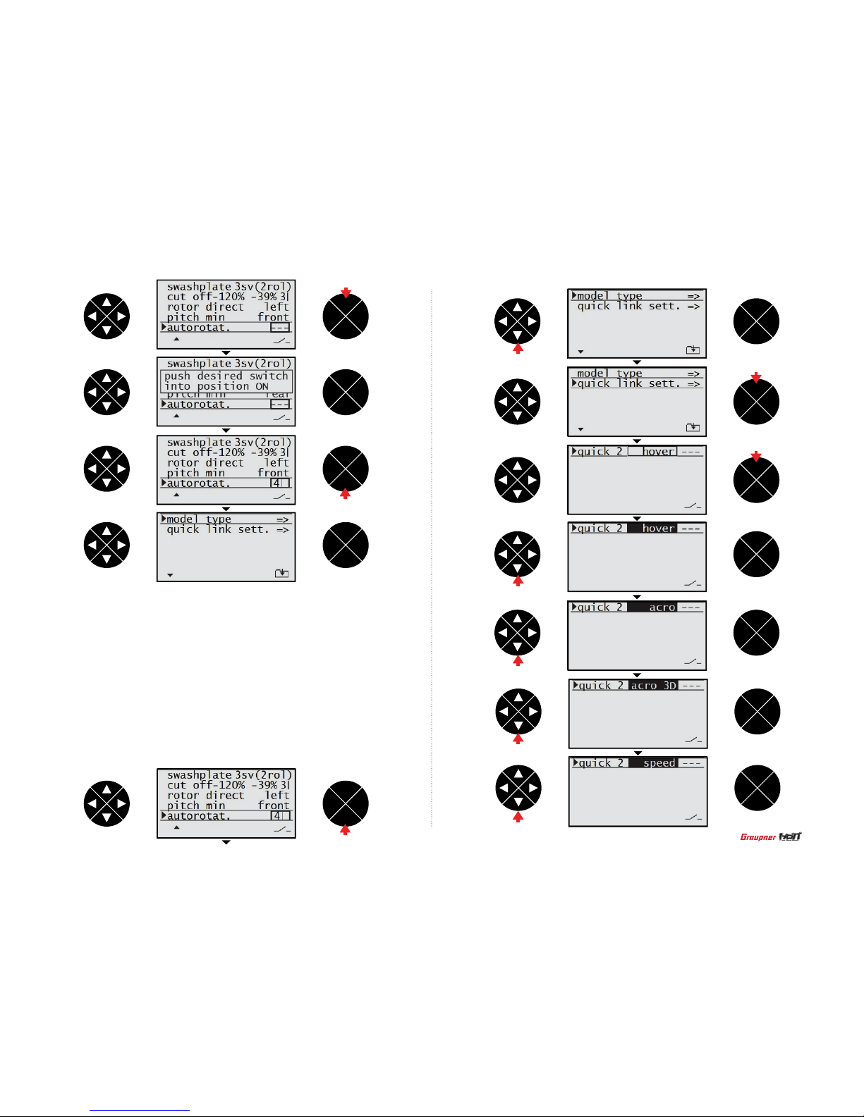
- Quick link sett
The quick link sett function allows to adjust the quick2 value and assign the corresponding
switch to cope with various ight conditions such as 3D ight or the ight with the strong wind.
Since the adjusted value is activated by moving the switch, you can cope with various ight
conditions with switch. It makes you operating the ight much easier.
You can select hover, acro, acro 3D, speed and test at the quick2 line.
Press the direction button to select the quick link sett line then press the ENT button to access
the function. The cursor is on the default value, hover, in the quick 2 line then press the ENT
button to highlight. Press the direction button to select the desired value then press the ENT
button to remove the highlight. Press the direction button to select the hyphen then press the
ENT button. The popup message “push desired switch into position ON” appears. Move the
switch to the desired position then the corresponding value appears. Press the ESC button to
get back to the m.type + quick screen. The quick link function is connected to the D/R expo and
the heli mix functions so the different value of the normal and quick2 can be programmed to
the D/R expo and the heli mix functions.
ENT
ESC
TEL VIW
ENT
ESC
TEL VIW
ENT
ESC
TEL VIW
ENT
ESC
TEL VIW
ENT
ESC
TEL VIW
ENT
ESC
TEL VIW
ENT
ESC
TEL VIW
ENT
ESC
TEL VIW
ENT
ESC
TEL VIW
ENT
ESC
TEL VIW
press
press
press
ENT
ESC
TEL VIW
ENT
ESC
TEL VIW
press
press
press
press
press
press
press
23
Page 24

3. Servo sett (Aircraft and Helicopter)
- Rev : used to reverse the servo direction for all channels.
- Cent : used to set the neutral position of the servo.
- Trv : used to increase or decrease the moving angle of the servo travel.
ENT
ESC
TEL VIW
ENT
ESC
TEL VIW
ENT
ESC
TEL VIW
ENT
ESC
TEL VIW
ENT
ESC
TEL VIW
ENT
ESC
TEL VIW
ENT
ESC
TEL VIW
ENT
ESC
TEL VIW
ENT
ESC
TEL VIW
ENT
ESC
TEL VIW
press
press
The servo sett adjusts the servo reverse, center, travel for all six channels.
- Rev (Reverse)
Press the direction button to highlight the servo sett then press the ENT button to access the
function. The cursor is at the rev value, the arrow mark, in the S1 line then press the ENT
button to highlight the arrow mark. Press the direction button then the arrow mark is reversed
and the direction of the servo in S1 (throttle channel) is reversed. Press the ENT button to
remove the highlight. The S2~S6 channels can be program in the same method with the S1.
- Cent (Center)
Press the direction button to select the cent value in the S1 line then press the ENT button to
highlight the value. Press the direction button to adjust the desired center value. Check the
neutral position of the model with adjusting the center value of the S1. Press the ENT button to
remove the highlight. The S2~S6 channels can be program in the same method with the S1.
- Trv (Travel)
Press the direction button to select the trv value of the S1 line then press the ENT button to
highlight the value. Press the direction button to adjust the desired value then press the ESC
button to remove the highlight. Move the stick to select the other tr v value then press the ENT
button to highlight. Press the direction button to select desired value. Press the ENT button
to remove the highlight and press ESC button get back to the menu screen. The S2~S6
channels can be program in the same method with the S1.
press
press
press
press
press
24
Page 25

ENT
ESC
TEL VIW
ENT
ESC
TEL VIW
ENT
ESC
TEL VIW
ENT
ESC
TEL VIW
ENT
ESC
TEL VIW
ENT
ESC
TEL VIW
ENT
ESC
TEL VIW
ENT
ESC
TEL VIW
ENT
ESC
TEL VIW
ENT
ESC
TEL VIW
ENT
ESC
TEL VIW
ENT
ESC
TEL VIW
press
press
press
ENT
ESC
TEL VIW
ENT
ESC
TEL VIW
press
press
press
press
press
press
press
press
press
press
25
Page 26

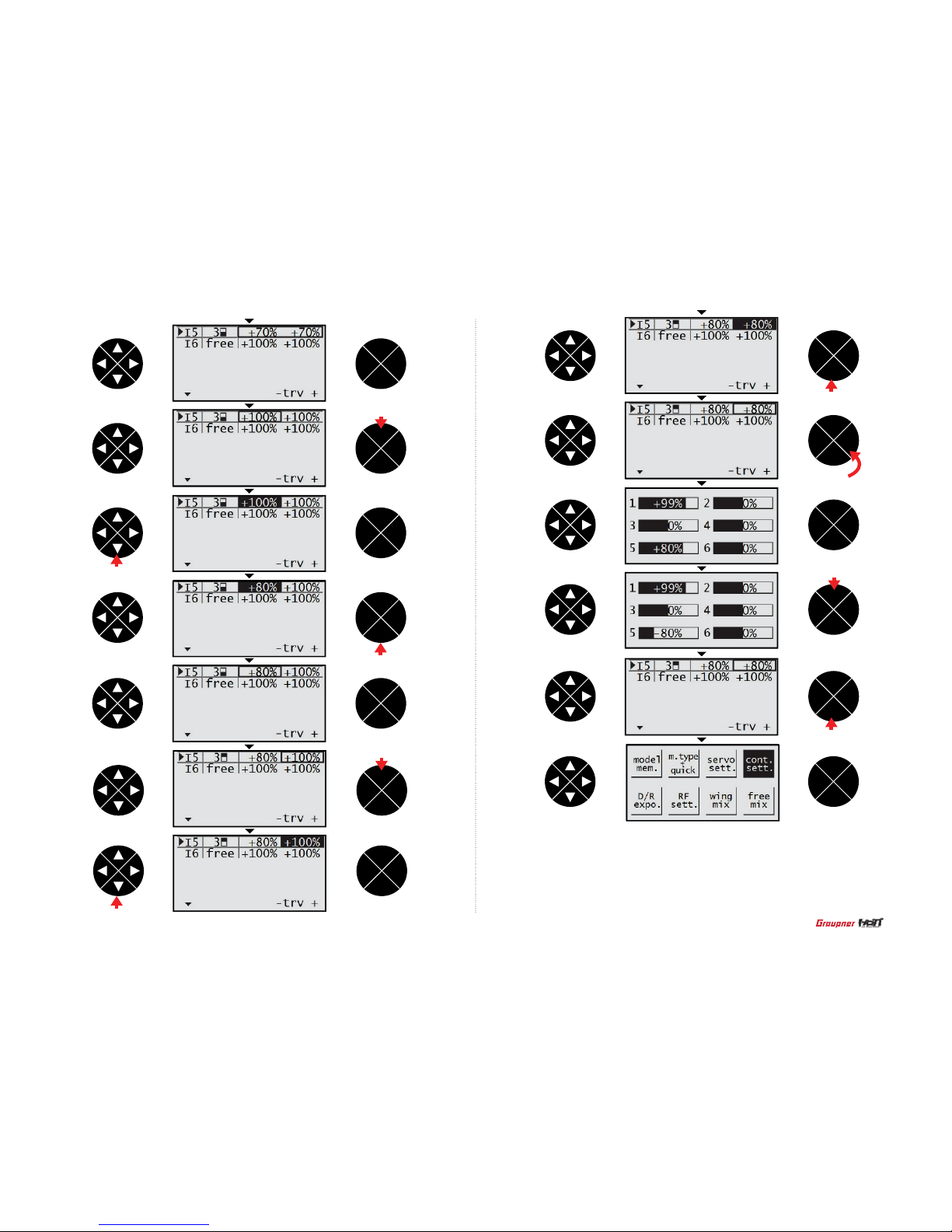
4. Cont sett (Aircraft and Helicopter)
It contains 3 categories: model type, quick link set and quick link trim. You can program the 5
and 6 channels in mz-12 to the special function that you want. Typically, the 5 channel is used for
the on/off switch of the retractor gear and the 6 channel is used for the on/off switch of the ap
function. The special 2 channels are widely used, depending on the airplane wing type.
- Cont sett (AIRCRAFT)
Press the direction button to highlight the cont sett then press the ENT button to access the
function. The cursor is at the free of I5 line. Press the ENT button then the pop up message
“operate desired switch or control” appears. Move the switch or the volume that you want to use,
then they are set to the special channels. Here is the example that the NO.3 switch is set. Press
the direction button to select the trv value then press the ENT button. Both of – value and + value
are simultaneously highlighted. Press the direction button to adjust the desired value (If you press
the VIW button, you can check the adjusted value) then press the ESC button to get back to the
menu screen. The 6 channel can be programmed with the same method with the channel 5.
NOTE : If you move the switch or volume that is designated as the special channel, the cursor
is moved to the corresponding value then you can adjust each of – value and + value. Press the
ENT to highlight the value then press the direction buttons to adjust the desired the value.
ENT
ESC
TEL VIW
ENT
ESC
TEL VIW
ENT
ESC
TEL VIW
ENT
ESC
TEL VIW
ENT
ESC
TEL VIW
ENT
ESC
TEL VIW
ENT
ESC
TEL VIW
ENT
ESC
TEL VIW
ENT
ESC
TEL VIW
ENT
ESC
TEL VIW
press
press
press
ENT
ESC
TEL VIW
press
press
press
press
press
press
26
Page 27
ENT
ESC
TEL VIW
ENT
ESC
TEL VIW
ENT
ESC
TEL VIW
ENT
ESC
TEL VIW
ENT
ESC
TEL VIW
ENT
ESC
TEL VIW
ENT
ESC
TEL VIW
ENT
ESC
TEL VIW
ENT
ESC
TEL VIW
ENT
ESC
TEL VIW
ENT
ESC
TEL VIW
ENT
ESC
TEL VIW
press
press
press
press
ENT
ESC
TEL VIW
- Cont sett (Helicopter)
The basic setting of the Helicopter cont sett is NO.5 gyro, NO6. Throttle, Lim. DV (Digital volume).
Generally, this function is seldom used, but Lim. DV (Digital volume) can control the operation
range of digital volume -100 ~ +100. If DV is programmed, throttle channel is operated only
programmed range.
press
press
press
press
press
27
Page 28

5. D/R expo (Aircraft and Helicopter)
The basic setting of the Helicopter cont sett is NO.5 gyro, NO6. Throttle, Lim. DV (Digital volume).
Generally, this function is seldom used, but Lim. DV (Digital volume) can control the operation
range of digital volume -100 ~ +100. If DV is programmed, throttle channel is operated only
programmed range.
- D/R
Affects the overall travel which in turn affects control response sensitivity equally throughout the
range of that channel. Reducing the dual rate reduces the maximum control rate as well as overall
sensitivity.After programming the max moving angle of the servo at the servo sett function, the
D/R switch is ON, the basic value of the normal ight can be programmed. Depending on the
D/R switch is on/off, the Aircraft to have a high control rate for aggressive maneuvers and a low
control for smooth, precise maneuvers.
- Expo
Affects the sensitivity around center but has no affect on the overall travel. Positive Exponential
reduces control sensitivity around neutral for more precise control but does not affect the maximum control response. Negative exponential increase control sensitivity around neutral.
- D/R expo
Press the direction button to highlight the D/R expo then press the ENT button to access the
function. The cursor is at the dual value of the aileron channel. Press the ENT and the directions
button to highlight and adjust the desired value then press the ESC and the direction buttons to
select the expo value in the aileron channel. Press the ENT and the direction buttons to highlight
and adjust the desired value then the press the ESC and the direction button to select the hyphen.
Press the ENT button then the pop up message “push desired switch into position on” appears.
Move the switch that you want to assign as the dual on/off . That switch is assigned to the aileron
dual on/off switch.
NOTE : If the quick link switch is ON when the quick link function is activated, the dual value can
be programmed to go with the purpose of the quick link The elevator and rudder channels can be
program in the same method with the aileron channel.
ENT
ESC
TEL VIW
ENT
ESC
TEL VIW
ENT
ESC
TEL VIW
ENT
ESC
TEL VIW
ENT
ESC
TEL VIW
ENT
ESC
TEL VIW
ENT
ESC
TEL VIW
ENT
ESC
TEL VIW
ENT
ESC
TEL VIW
press
press
press
press
press
press
press
press
press
28
Page 29

6. RF sett (Aircraft and Helicopter)
The RF function of the transmitter can be programmed, it contains 6 models of stick mode,
timer, receiv out, rx bind, range test, RF transmit.
•
Stick mode
The mz-12 has four stick modes with the two dual axis sticks. The user can select one among
the four default stick modes the default mode is the mode 1.
•
Timer
The mz-12 has four stick modes with the two dual axis sticks. The user can select one among
the four default stick modes the default mode is the mode 1.
•
Receiv out
For the maximum exibility of the receiver socket assignment, the mz-12 provides to swap over
the servo outputs 1 to max.6. If you try to use more than 1 servos at the aileron or the elevator or
the rudder, the receiver output socket can be assigned as you intend.
•
Rx bind : The receiver must be bound to the transmitter before the receiver will operate. Binding
teaches the receiver the specic code of the transmitter, so it will only connect to that transmitter.
•
Range test : The Range Test function reduces the power output. This allows for a range test to
conrm the RF link is operating correctly. Perform a range check at the beginning of each ying
session to conrm system operation.
•
RF transmit : RF transmit function allows to turn on/off the RF power output
ENT
ESC
TEL VIW
ENT
ESC
TEL VIW
ENT
ESC
TEL VIW
ENT
ESC
TEL VIW
ENT
ESC
TEL VIW
ENT
ESC
TEL VIW
ENT
ESC
TEL VIW
press
press
press
29
Page 30

- Stick mode
Enter the stick mode from the RF sett on the menu. Press the ENT button to highlight the value
then press the direction button to select the mode number of 4 modes.
- Timer
Press the direction button to select the timer line and press the direction button again to select
the minute or second. Press the ENT button to highlight the value then press the direction button
to adjust the desired. Press the ESC button to remove the highlight then press the direction button to select the hyphen. Press the ENT button then the popup message “push desired switch
onto position ON” appears. Move the switch then the corresponding value appears (The timer
function is on/off when the switch is moved). Press the ESC button to remove the highlight.
ENT
ESC
TEL VIW
ENT
ESC
TEL VIW
ENT
ESC
TEL VIW
ENT
ESC
TEL VIW
ENT
ESC
TEL VIW
press
press
ENT
ESC
TEL VIW
ENT
ESC
TEL VIW
ENT
ESC
TEL VIW
ENT
ESC
TEL VIW
ENT
ESC
TEL VIW
ENT
ESC
TEL VIW
ENT
ESC
TEL VIW
press
press
press
press
press
press
press
press
press
30
Page 31

- Receiv out
Press the direction button to select the receiv out line then press the ENT button to access the
function. The cursor is on the arrow mark then press the ENT button to access the function.
T h e d e f a u l t c h a n n e l a s s i g n m e n t a p p e a r s o n t h e s c r e e n .
Press the direction button to select S1~S6 then press the
ENT and the direction buttons to highlight and change to
the desired channel. Press the ESC button to get back to
the previous screen.
NOTE: If you change S1 to S2, the S2 have the 2 channels of output 1 and output 2 so the both servo of output
1 and output 2 are simultaneously moved when the stick
of the S2 is move.
- Rx bind
Press the direction button to select rx bind line then the cursor is at the hyphen. Turn on the
receiver then press the ENT button on the receiver for over 3 seconds so that the receiver
enter the binding mode. Press the ENT button of the transmitter, the system will be connected within a few seconds and the model name of the receiver is displayed on the screen after
completing the bind.
- Range test
Press the direction button to select the range test, the cursor is at the 99sec. Turn on the receiver then press the ENT button on the transmitter. With the range test started, the Graupner
logo blinks with beep for 99sec. Walk over 50 meters away from the model with controlling the
transmitter sticks constantly and check whether the model is operating normally. You should
have total control of the model with the trainer switch pulled.
ENT
ESC
TEL VIW
ENT
ESC
TEL VIW
ENT
ESC
TEL VIW
ENT
ESC
TEL VIW
ENT
ESC
TEL VIW
ENT
ESC
TEL VIW
ENT
ESC
TEL VIW
ENT
ESC
TEL VIW
ENT
ESC
TEL VIW
ENT
ESC
TEL VIW
press
press
press
press
-The default channel assignment-
Channel
Throttle S1
S2
S3
S4
S5
S6
Aileron
Elevator
Rudder
5 Channel
6 Channel
Output
Output 1
Output 2
Output 3
Output 4
Output 5
Output 6
press
press
31
Page 32
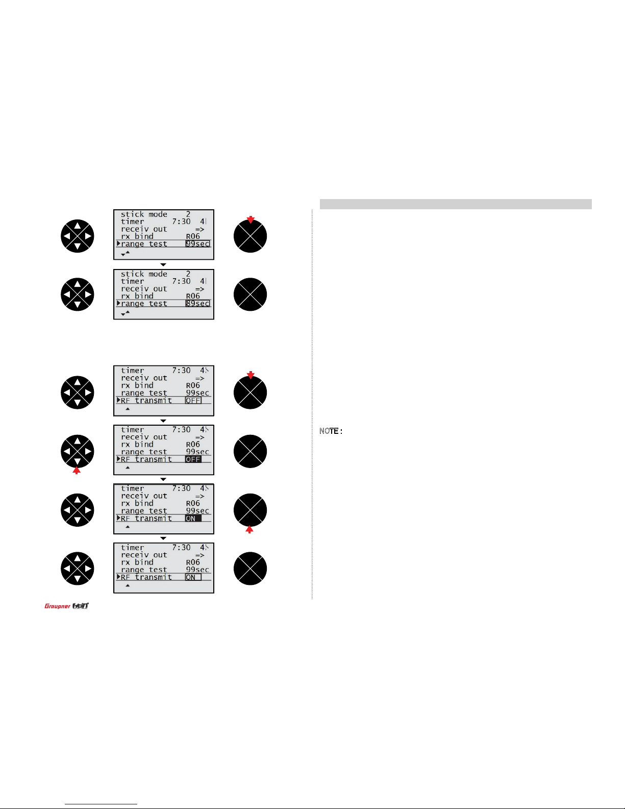
- RF transmit
RF transmit function allows to turn ON/OFF the RF power output.
Press the direction button to select the RF transmit then press the ENT button to select ON or
OFF.
7. wing mix (AIRCRAFT)
•
Diff aile
The diff aile mixing allows to overcome the adverse yaw when the Aircraft is deected. the
servo travel of the aileron channel is so adjusted that the ight vertical axis is straightened.
•
Diff aps
The diff aps mixing allows the aileron channel to be mixed to the ap channel. If the aileron
is operated, the ap is simultaneously operated. This mixing help to overcome adverse yaw
characteristics as well.
•
Aile->rudd
The aileron to rudder mixing allows to overcome adverse yaw characteristics with the glider or
the scale Aircraft and makes coordinating turns easier. When the aileron command is given,
both of the aileron and the rudder are operated simultaneously.
•
Aile->aps
The aileron to falp mixing allows enhance the performance of the roll ight. When the aileron
command is given, both of the aileron and the ap are operated simultaneously.
•
Brak->elev
When the air brake of the glider has been programmed with the value of the motor at C1 being
no or no/inv, the air brake usually cause the ight nose up and down. The brake to elevator mixing offers the down and up signal to the elevator to compensate for the ight nose up and down.
•
Brak->ap
When the air brake (with the value of the motor at C1 being no or no/inv) is operated, both ap
servos is simultaneously moved for the landing approach. You can program the travel direction
and range of the ap servos.
•
Brak->aile
When the air brake (with the value of the motor at C1 being no or no/inv) is operated, both
aileron servos is simultaneously moved for the landing approach. You can program the travel
direction and range of the aileron servos.
NOTE : The typical programming for the air brake is that the aileron up, the ap down and the
elevator up.
•
Elev->ap
The elevator to ap mixing allows the elevator channel to be mixed to the ap channel. If the
elevator is operated, the ap is simultaneously operated. This mixing help to enhance the effect
of the elevator in tight turns and aerobatics. The typical programming for elevator to ap is that
the elevator up and the ap down.
•
Elev->aile
The elevator to ap mixing allows the elevator channel to be mixed to the aileron channel. If the
elevator is operated, the aileron is simultaneously operated. This mixing help to reinforce the
elevator response. The typical programming is elevator up to aileron down and elevator down to
aileron up.
•
Flap->elev
When the ap command is given, both of the ap, the ight nose up and down. The ap to
elevator mixing offers the down and up signal to the elevator to compensate for the ight nose
up and down.
•
Flap->aile
When the ap command is given, both of the ap and the aileron are operated simultaneously.
Diff-red
The differential reduction mixing allows the differential aileron mixing to work, even in the
situation that the airbrake (the aileron up, the ap down) is programmed so that you can’t use
the differential aileron mixing.
ENT
ESC
TEL VIW
ENT
ESC
TEL VIW
ENT
ESC
TEL VIW
ENT
ESC
TEL VIW
ENT
ESC
TEL VIW
ENT
ESC
TEL VIW
press
press
press
press
32
Page 33

- Diff ap
Press the direction button to select the diff aps line and press the ENT button to highlight the
value. Press the direction button to adjust the desired value then press the ESC button to remove the highlight. Press the direction button to select the hyphen then press the ENT button.
The popup message “push desired switch into position on” appears. Move the switch then the
corresponding value appears (The diff aps mixing is on/off when the switch is moved). Press
the direction button to select other mixing.
- Diff aile
Press the ENT button to access the diff aile mixing then press the ENT button again
to highlight the value. Press the direction button to adjust the desired value then press
the ESC button to remove the highlight. Press the direction button to select the hyphen
then press the ENT button. The popup message “push desired switch into position on”
appears. Move the switch then the corresponding value appears (The diff aile mixing is
on/off when the switch is moved). Press the direction button to select other mixing.
ENT
ESC
TEL VIW
ENT
ESC
TEL VIW
ENT
ESC
TEL VIW
ENT
ESC
TEL VIW
ENT
ESC
TEL VIW
ENT
ESC
TEL VIW
ENT
ESC
TEL VIW
ENT
ESC
TEL VIW
ENT
ESC
TEL VIW
ENT
ESC
TEL VIW
ENT
ESC
TEL VIW
press
press
press
press
ENT
ESC
TEL VIW
press
press
press
press
press
press
press
33
Page 34
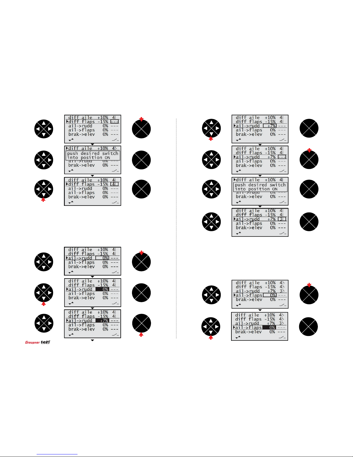
- Ail->rudd
Press the direction button to select the ail -> rudd line and press the ENT button to highlight
the value. Press the direction button to adjust the desired value then press the ESC button to
remove the highlight. Press the direction button to select the hyphen then press the ENT button. The popup message “push desired switch into position on” appears. Move the switch then
the corresponding value appears (The ail -> rudd mixing is on/off when the switch is moved).
Press the direction button to select other mixing.
- Ail->ap
Press the direction button to select the ail -> aps line and press the ENT button to highlight
the value. Press the direction button to adjust the desired value then press the ESC button to
remove the highlight. Press the direction button to select the hyphen then press the ENT button. The popup message “push desired switch into position on” appears. Move the switch then
the corresponding value appears (The ail -> aps mixing is on/off when the switch is moved).
Press the direction button to select other mixing.
ENT
ESC
TEL VIW
ENT
ESC
TEL VIW
ENT
ESC
TEL VIW
ENT
ESC
TEL VIW
ENT
ESC
TEL VIW
ENT
ESC
TEL VIW
ENT
ESC
TEL VIW
ENT
ESC
TEL VIW
ENT
ESC
TEL VIW
ENT
ESC
TEL VIW
ENT
ESC
TEL VIW
ENT
ESC
TEL VIW
press
press
press
press
press
press
press
press
press
34
Page 35

- Brak->elev
Press the direction button to select the brak -> elev line and press the ENT button to
highlight the value. Press the direction button to adjust the desired value then press
the ESC button to remove the highlight. Press the direction button to select the hyphen
then press the ENT button. The popup message “push desired switch into position on”
appears. Move the switch then the corresponding value appears (The brak -> elev mixing
is on/off when the switch is moved). Press the direction button to select other mixing.
ENT
ESC
TEL VIW
ENT
ESC
TEL VIW
ENT
ESC
TEL VIW
ENT
ESC
TEL VIW
ENT
ESC
TEL VIW
ENT
ESC
TEL VIW
ENT
ESC
TEL VIW
ENT
ESC
TEL VIW
ENT
ESC
TEL VIW
ENT
ESC
TEL VIW
ENT
ESC
TEL VIW
ENT
ESC
TEL VIW
press
press
press
press
press
press
press
press
35
Page 36

- Brak->aile
Press the direction button to select the brak -> aile line and press the ENT button to highlight
the value. Press the direction button to adjust the desired value then press the ESC button to
remove the highlight. Press the direction button to select the hyphen then press the ENT button. The popup message “push desired switch into position on” appears. Move the switch then
the corresponding value appears (The brak -> aile mixing is on/off when the switch is moved).
Press the direction button to select other mixing.
- Brak->ap
Press the direction button to select the brak -> ap line and press the ENT button to highlight
the value. Press the direction button to adjust the desired value then press the ESC button
to remove the highlight. Press the direction button to select the hyphen then press the ENT
button. The popup message “push desired switch into position on” appears. Move the switch
then the corresponding value appears (The brak -> ap mixing is on/off when the switch is
moved). Press the direction button to select other mixing.
ENT
ESC
TEL VIW
ENT
ESC
TEL VIW
ENT
ESC
TEL VIW
ENT
ESC
TEL VIW
ENT
ESC
TEL VIW
ENT
ESC
TEL VIW
ENT
ESC
TEL VIW
ENT
ESC
TEL VIW
ENT
ESC
TEL VIW
ENT
ESC
TEL VIW
ENT
ESC
TEL VIW
ENT
ESC
TEL VIW
press
press
press
press
press
press
press
press
press
press
36
Page 37

ENT
ESC
TEL VIW
ENT
ESC
TEL VIW
ENT
ESC
TEL VIW
ENT
ESC
TEL VIW
ENT
ESC
TEL VIW
ENT
ESC
TEL VIW
- Elev->ap
Press the direction button to select the elec -> ap line and press the ENT button to highlight
the value. Press the direction button to adjust the desired value then press the ESC button
to remove the highlight. Press the direction button to select the hyphen then press the ENT
button. The popup message “push desired switch into position on” appears. Move the switch
then the corresponding value appears (The elec -> ap mixing is on/off when the switch is
moved). Press the direction button to select other mixing.
- Elev->aile
Press the direction button to select the elec -> aile line and press the ENT button to highlight
the value. Press the direction button to adjust the desired value then press the ESC button
to remove the highlight. Press the direction button to select the hyphen then press the ENT
button. The popup message “push desired switch into position on” appears. Move the switch
then the corresponding value appears (The elec -> aile mixing is on/off when the switch is
moved). Press the direction button to select other mixing.
press
press
ENT
ESC
TEL VIW
ENT
ESC
TEL VIW
ENT
ESC
TEL VIW
ENT
ESC
TEL VIW
ENT
ESC
TEL VIW
ENT
ESC
TEL VIW
press
press
press
press
press
press
press
37
Page 38

- Flap->elev
Press the direction button to select the ap -> elev line and press the ENT button to highlight
the value. Press the direction button to adjust the desired value then press the ESC button to
remove the highlight. Press the direction button to select the hyphen then press the ENT button.
The popup message “push desired switch into position on” appears. Move the switch then the
corresponding value appears (The ap -> elev mixing is on/off when the switch is moved). Press
the direction button to select other mixing.
- Flap->aile
Press the direction button to select the ap -> aile line and press the ENT button to highlight
the value. Press the direction button to adjust the desired value then press the ESC button to
remove the highlight. Press the direction button to select the hyphen then press the ENT button. The popup message “push desired switch into position on” appears. Move the switch then
the corresponding value appears (The ap -> aile mixing is on/off when the switch is moved).
Press the direction button to select other mixing.
ENT
ESC
TEL VIW
ENT
ESC
TEL VIW
ENT
ESC
TEL VIW
ENT
ESC
TEL VIW
ENT
ESC
TEL VIW
ENT
ESC
TEL VIW
ENT
ESC
TEL VIW
ENT
ESC
TEL VIW
ENT
ESC
TEL VIW
ENT
ESC
TEL VIW
ENT
ESC
TEL VIW
ENT
ESC
TEL VIW
press
press
press
press
press
press
press
press
38
Page 39
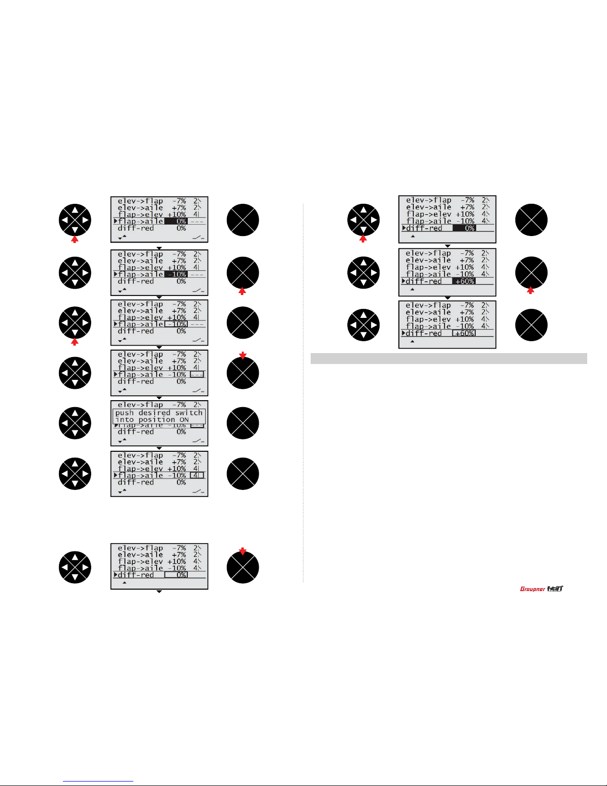
- Diff-red
Press the direction button to access the dif f-red mixing then press the ENT button to highlight the value. Press the direction button to adjust the desired value then press the ESC
button to remove the highlight.
8. heli mix (Helicopter)
The mz-12 offers the mixing function in Helicopter model type. Heli mix is connected to 2 quick link
function and the mixes are assigned to each quick link function.
•
Ptch : The ptch mixing allows to adjust 5 points of the pitch curve that corresponds to the throttle
stick to maintain the best ight condition. You can program the different pitch curve for each quick link.
•
Pitc-thro : pitc -> thro function allows to adjust 5 points of the throttle curve that corresponds to the
pitch angle for the throttle stick operation so that the engine or motor leads the best ight condition.
You can program the different throttle curve for each quick link.
•
Pitc-rudd : It is pitch rudder mixing. This function is used for offsetting the counter torque that is
generated by the pitch of the main rotor or the change of the motor/engine RPM in accordance with
the movement of the throttle stick. You can set the point at the position where the counter torque is
generated to program the rudder value. This mixing might not be necessary when the high performance Gyro (Tail lock) or might be need to adjust the small value. You can adjust the different value
for each quick link.
•
Rudd-thro : This function is used to offset to fall down Helicopter engine RPM by the load that is
generated for rudd operation during Helicopter hovering. It can be offset with throttle channel.
•
Aile-thro : This function is used to offset to fall down Helicopter engine RPM by the load that is
generated for aile operation during Helicopter hovering. It can be offset with throttle channel.
•
Elev-thro : This function is used to offset to fall down Helicopter engine RPM by the load that is
generated for elec operation during Helicopter hovering. It can be offset with throttle channel.
•
Gyro : The gyro mixing allows to adjust the gyro gain. You can adjust the different gyro gain for
each quick link.
•
Swash lim : If the aileron and elevator related with the swashplate is simultaneously controlled, the
linkage connected to the servo might be damaged. The swash lim mixing allows to restrict the travel
range of the swash plate to prevent the damage of the linkage. It is typically used for 3D Helicopter.
•
Governor 8ch : This function is used to set governor ON/OFF
•
Governor rate : This function is used to set the value of governor operation.
ENT
ESC
TEL VIW
ENT
ESC
TEL VIW
ENT
ESC
TEL VIW
ENT
ESC
TEL VIW
ENT
ESC
TEL VIW
ENT
ESC
TEL VIW
ENT
ESC
TEL VIW
ENT
ESC
TEL VIW
ENT
ESC
TEL VIW
ENT
ESC
TEL VIW
press
press
press
press
press
press
press
39
Page 40
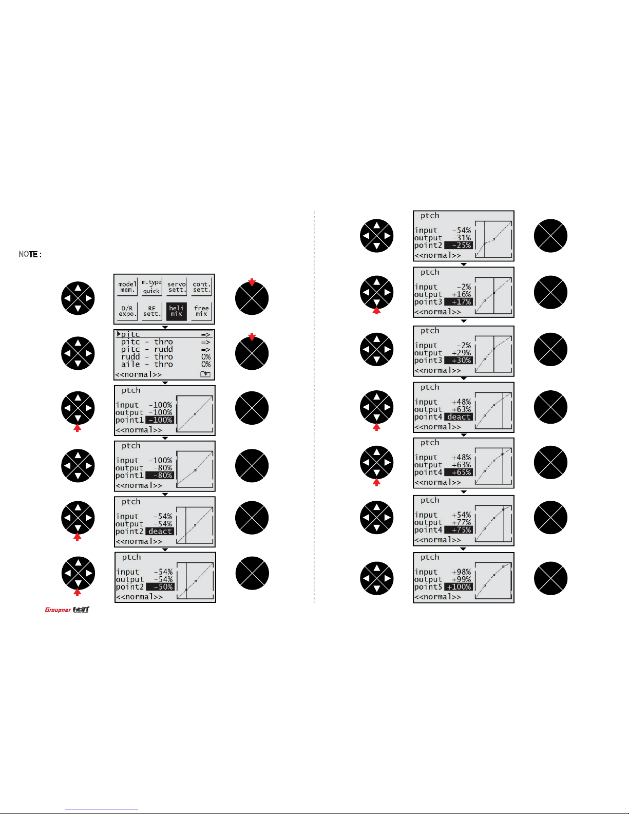
- Ptch
Press ENT button to access the ptch mixing then press the ENT button again to access the
function. -100% of the point 1 value is highlighted. Move the throttle stick to the high position
step by step then the point 2,3,4,5 is selected in turn. After selecting the point number, press
the direction button to adjust the desired value. Press the ESC button to return to the previous
screen.
NOTE : The default values of the point 2 and point 4 is remained not to be programmed so
the “deact” is displayed at the value box. You may activate and adjust the desired value by the
direction button if you want.
ENT
ESC
TEL VIW
ENT
ESC
TEL VIW
ENT
ESC
TEL VIW
ENT
ESC
TEL VIW
ENT
ESC
TEL VIW
ENT
ESC
TEL VIW
ENT
ESC
TEL VIW
ENT
ESC
TEL VIW
ENT
ESC
TEL VIW
ENT
ESC
TEL VIW
ENT
ESC
TEL VIW
ENT
ESC
TEL VIW
ENT
ESC
TEL VIW
press
press
press
press
press
press
press
press
40
Page 41
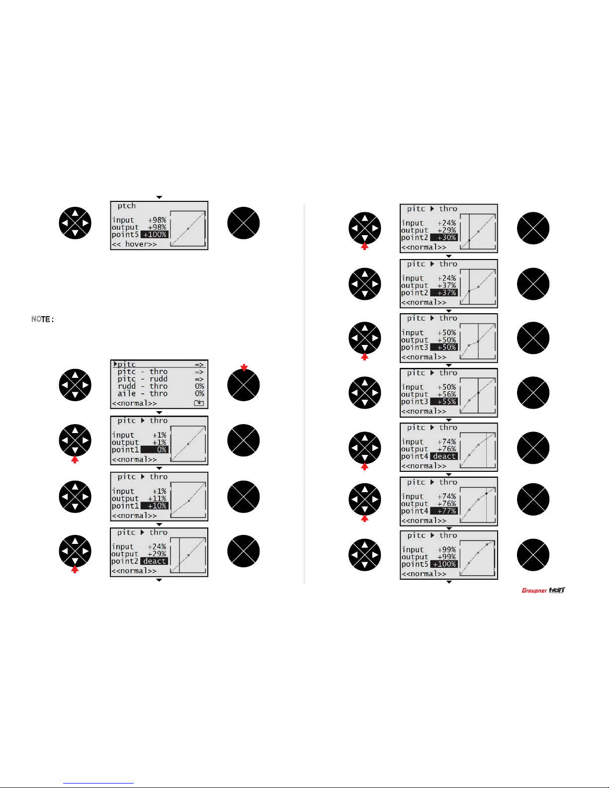
- Pitc->thro
Press the direction button to select pitc->thro line and press the ENT button to access the
pitc->thro function. 0% of the point 1 value is highlighted. Move the throttle stick to the
high position step by step then the point 2,3,4,5 is selected in turn. After selecting the point
number, press the direction button to adjust the desired value. Press the ESC button to
return to the previous screen.
NOTE : The default values of the point 2 and point 4 is remained not to be programmed so
the “deact” is displayed at the value box. You may activate and adjust the desired value by
the direction button if you want. When the value of the point 2 and point 4 are activated,
the basic value of point 2 is 25% and point 4 is 75%
ENT
ESC
TEL VIW
ENT
ESC
TEL VIW
ENT
ESC
TEL VIW
ENT
ESC
TEL VIW
ENT
ESC
TEL VIW
ENT
ESC
TEL VIW
ENT
ESC
TEL VIW
ENT
ESC
TEL VIW
ENT
ESC
TEL VIW
ENT
ESC
TEL VIW
ENT
ESC
TEL VIW
press
ENT
ESC
TEL VIW
press
press
press
press
press
press
41
Page 42

- Pitc->rudd
ruddPress the direction button to select pitc->tail line and press the ENT button to access the
pitc-> tail function. 0% of the point 1 value is highlighted. Move the throttle stick to the high
position step by step then the point 2,3,4,5 is selected in turn. After selecting the point number,
press the direction button to adjust the desired value. Press the ESC button to return to the
previous screen.
NOTE : The default values of the point 2 and point 4 is remained not to be programmed so
the “deact” is displayed at the value box. You may activate and adjust the desired value by the
direction button if you want.
ENT
ESC
TEL VIW
ENT
ESC
TEL VIW
ENT
ESC
TEL VIW
ENT
ESC
TEL VIW
ENT
ESC
TEL VIW
ENT
ESC
TEL VIW
ENT
ESC
TEL VIW
ENT
ESC
TEL VIW
ENT
ESC
TEL VIW
ENT
ESC
TEL VIW
ENT
ESC
TEL VIW
ENT
ESC
TEL VIW
ENT
ESC
TEL VIW
press
press
press
press
press
press
press
press
press
42
Page 43
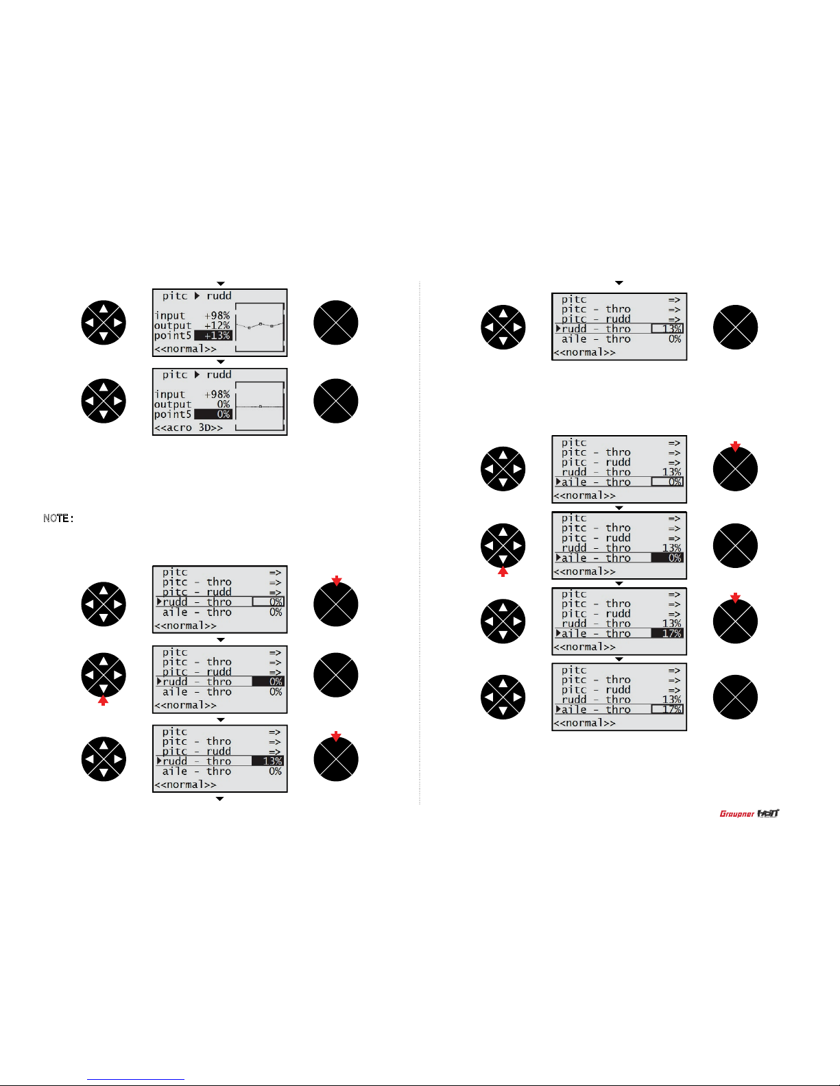
- Aile-thro
Press the direction button to select aile – thro line and press the ENT button to access the
aile – thro function. The value 0% is highlighted then press the direction button to adjust the
desired value.
- Rudd-thro
Press the direction button to select rudd – thro line and press the ENT button to access the
rudd – thro function. The value 0% is highlighted then press the direction button to adjust
the desired value.
NOTE : In case that the direction of Helicopter rotation is clockwise, rudd–thro function is
only operated when rudd is moved to the right side and if the direction of Helicopter rotation
is unclockwise, rudd–thro function is only operated when rudd is moved to the left side.
ENT
ESC
TEL VIW
ENT
ESC
TEL VIW
ENT
ESC
TEL VIW
ENT
ESC
TEL VIW
ENT
ESC
TEL VIW
ENT
ESC
TEL VIW
ENT
ESC
TEL VIW
ENT
ESC
TEL VIW
ENT
ESC
TEL VIW
ENT
ESC
TEL VIW
press
press
press
press
- Elev-thro
Press the direction button to select elev – thro line and press the ENT button to access the elev
– thro function. The value 0% is highlighted then press the direction button to adjust the desired
value.
press
press
43
Page 44

- Gyro
Press the direction button to select the gyro mixing line then press the ENT button to access the function. 0% of the gyro gain is highlighted. Press the direction button to adjust the
desired the gain then press the ESC button to remove the highlight.
- Swash lim
Press the direction button to select the swash lim mixing then press the ENT button to
access the function. off of the swash lim value is highlighted. Press the direction button to
adjust the desired the gain then press the ESC button to remove the highlight.
ENT
ESC
TEL VIW
ENT
ESC
TEL VIW
ENT
ESC
TEL VIW
ENT
ESC
TEL VIW
ENT
ESC
TEL VIW
ENT
ESC
TEL VIW
ENT
ESC
TEL VIW
ENT
ESC
TEL VIW
ENT
ESC
TEL VIW
ENT
ESC
TEL VIW
press
press
press
ENT
ESC
TEL VIW
ENT
ESC
TEL VIW
press
press
press
press
press
press
press
44
Page 45

- Free mixer
Press the ENT button to access the free mixer. The rst ?? at M1 line is highlighted then press
the ENT button to highlight the value. The rst ?? is for the master channel programming.
Press the direction button to select the master channel then press the ESC button to remove
the highlight. Press the direction and ENT buttons to select the next M1 ?? and highlight the
value. The next ?? is for the slave channel programming. Press the direction button to select the
slave channel then press the ESC button to remove the highlight. Press the direction button to
select the hyphen then press the ENT button then the popup message “push desired switch into
position on” appears. Move the switch then the corresponding value appears (The M1 free mixer
is on/off when the switch is moved).
Press the direction button to select the arrow mark then press the ENT button to access the free
mixer ratio. The SYM is highlighted then press the ENT button to highlight both values of the trv
line. Press the direction button to adjust the desired value. Both values are adjusted simultaneously and appeared in the diagram.
9. free mixer (Aircraft and Helicopter)
The free mixer allows to select the master channel that is controlling channel and the salve
channel. The Master channel will be mixed to the slave channel and the slave channel will follow
the master channels input based on the rate that is programmed. Three free mixers are available
for each of the ten model memories.
- Governor 8ch
Press the direction button to select the governor 8ch then press the ENT button to access
the function. The value no of is highlighted. You may select yes or no by the direction
button. Press the ESC button to remove the highlight.
- Governor rate
Press the direction button to select the governor rate then press the ENT button to access the function. The value 0% of is highlighted. Press the direction button to adjust the
desired value then press the ESC button to remove the highlight.
ENT
ESC
TEL VIW
ENT
ESC
TEL VIW
ENT
ESC
TEL VIW
ENT
ESC
TEL VIW
ENT
ESC
TEL VIW
ENT
ESC
TEL VIW
ENT
ESC
TEL VIW
ENT
ESC
TEL VIW
ENT
ESC
TEL VIW
press
press
press
press
press
45
Page 46

ENT
ESC
TEL VIW
ENT
ESC
TEL VIW
press
press
ENT
ESC
TEL VIW
ENT
ESC
TEL VIW
ENT
ESC
TEL VIW
ENT
ESC
TEL VIW
ENT
ESC
TEL VIW
ENT
ESC
TEL VIW
ENT
ESC
TEL VIW
ENT
ESC
TEL VIW
ENT
ESC
TEL VIW
ENT
ESC
TEL VIW
ENT
ESC
TEL VIW
ENT
ESC
TEL VIW
press
press
press
press
press
press
press
press
press
press
press
46
Page 47

- STO
Press the direction button to select the offset line then the STO is highlighted. Move the stick of
the mater channel till the vertical line on the diagram is moved to the desired position then press
the ENT button. The offset value is assigned at that position.
- ASY
To adjust the different value for the master channel, press the direction button to highlight the
ASY from the SYM then press the ENT button to highlight the trv value in the right. Move the
stick of the master channel then you can select the trv value in the right side or left side. Press
the direction button to adjust the desired value. Both trv values are appeared in the diagram.
ENT
ESC
TEL VIW
ENT
ESC
TEL VIW
ENT
ESC
TEL VIW
ENT
ESC
TEL VIW
ENT
ESC
TEL VIW
ENT
ESC
TEL VIW
ENT
ESC
TEL VIW
ENT
ESC
TEL VIW
ENT
ESC
TEL VIW
ENT
ESC
TEL VIW
ENT
ESC
TEL VIW
ENT
ESC
TEL VIW
press
press
press
press
press
press
press
press
press
press
47
Page 48
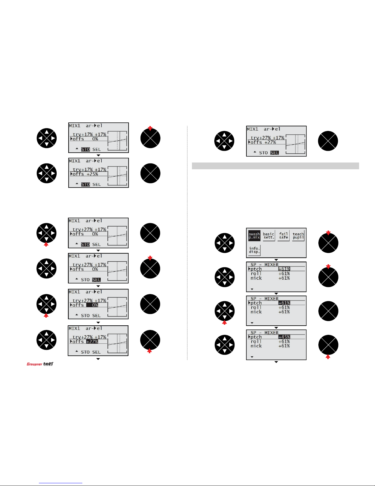
- SEL
Press the direction button to select the offset line then the STO is highlighted. Press the direction button to select the SEL then press the ENT button to highlight the offset value. Press the
direction button to adjust the desired value then press the ESC button to remove the highlight.
10. Swash mix (Helicopter)
The Swash mix adjusts the amount and direction of travel for the aileron, elevator and pitch
functions. You can adjust the high/low travel range of the swashplate and prevent from the
mechanical interference of the linkage.
Press the direction button to highlight the swqashp.mix then press the ENT button to access
the function. The ptch, roll and nick are available. Press the direction button to select one of
them then press the ENT and the direction buttons to highlight and adjust the value. Press
the ESC button to remove the highlight.
ENT
ESC
TEL VIW
ENT
ESC
TEL VIW
ENT
ESC
TEL VIW
ENT
ESC
TEL VIW
ENT
ESC
TEL VIW
ENT
ESC
TEL VIW
ENT
ESC
TEL VIW
ENT
ESC
TEL VIW
ENT
ESC
TEL VIW
1 time press
press
press
ENT
ESC
TEL VIW
ENT
ESC
TEL VIW
press
press
press
press
press
press
48
Page 49

- Batt type
Press the direction button to highlight the basic sett then press the ENT button to access the
Batt type line. Press the ENT button to highlight the value then press the direction button to
adjust the value. Press the ESC button to remove the highlight. You may select the function of
which you wish to adjust the value by pressing the direction button.
11. Basic sett (Aircraft and Helicopter)
ENT
ESC
TEL VIW
ENT
ESC
TEL VIW
ENT
ESC
TEL VIW
ENT
ESC
TEL VIW
ENT
ESC
TEL VIW
ENT
ESC
TEL VIW
ENT
ESC
TEL VIW
ENT
ESC
TEL VIW
press
press
•
Batt type
The battery that is used to the transmitter can be selected. NiMH and LiPo are available.
•
Batt warning
When the transmitter voltage drops below the preset voltage, the transmitter beeps the alarm
to warn the low battery.
•
Touch sense
The touch sense is used for adjusting the sensitivity of the button. The available values are
1~10. The lower the value, the more sensitive.
•
Contrast
Use the contrast to adjust contrast of the LCD. The available values are -20~20. The lower
the value, the more bright.
•
Display light
The backlighting time is adjusted.
•
Rf country
mz-12 offers 2 modes of GENERAL and FRANCE. You need the France RF setting to comply
with France regulations in FANCE. France RF setting should only be turned on when operating your transmitter in France outdoors.
•
Voice volume
The volume of the telemetry is adjusted.
•
Beep volume
The beep volume is adjusted.
press
press
press
press
49
Page 50
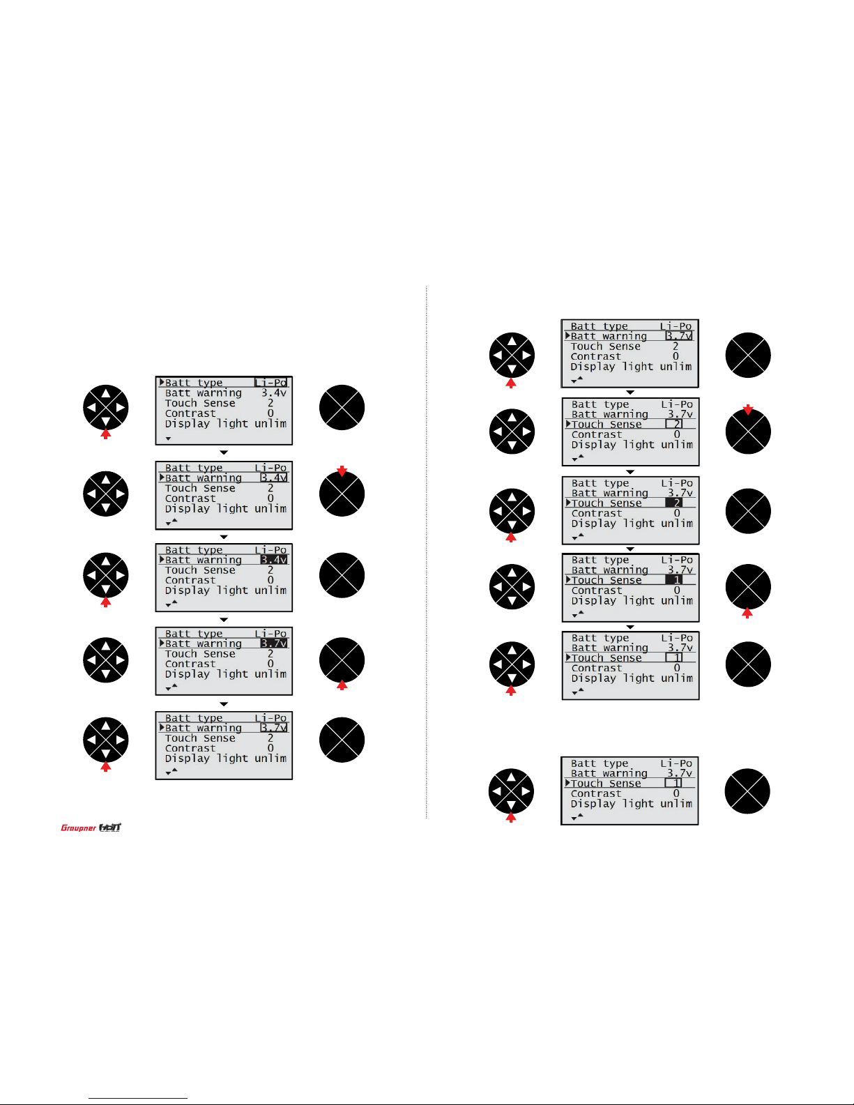
- Batt warning
Press the direction button to access the Batt warning line then press the ENT button to highlight
the value. Press the direction button to adjust the value. Press the ESC button to remove the
highlight.
- Touch sense
The same method is used to access the function and adjust the value with Batt type programming.
- Contrast
The same method is used to access the function and adjust the value with Batt type
programming.
ENT
ESC
TEL VIW
ENT
ESC
TEL VIW
ENT
ESC
TEL VIW
ENT
ESC
TEL VIW
ENT
ESC
TEL VIW
ENT
ESC
TEL VIW
ENT
ESC
TEL VIW
ENT
ESC
TEL VIW
ENT
ESC
TEL VIW
ENT
ESC
TEL VIW
ENT
ESC
TEL VIW
press
press
press
press
press
press
press
press
press
press
press
50
Page 51

- Display light
The same method is used to access the function and adjust the value with Batt type
programming.
ENT
ESC
TEL VIW
ENT
ESC
TEL VIW
ENT
ESC
TEL VIW
ENT
ESC
TEL VIW
ENT
ESC
TEL VIW
ENT
ESC
TEL VIW
ENT
ESC
TEL VIW
ENT
ESC
TEL VIW
ENT
ESC
TEL VIW
press
press
- RF country
The same method is used to access the function and adjust the value with Batt type program-
ming.
ENT
ESC
TEL VIW
ENT
ESC
TEL VIW
ENT
ESC
TEL VIW
press
press
press
press
press
press
press
press
press
press
51
Page 52
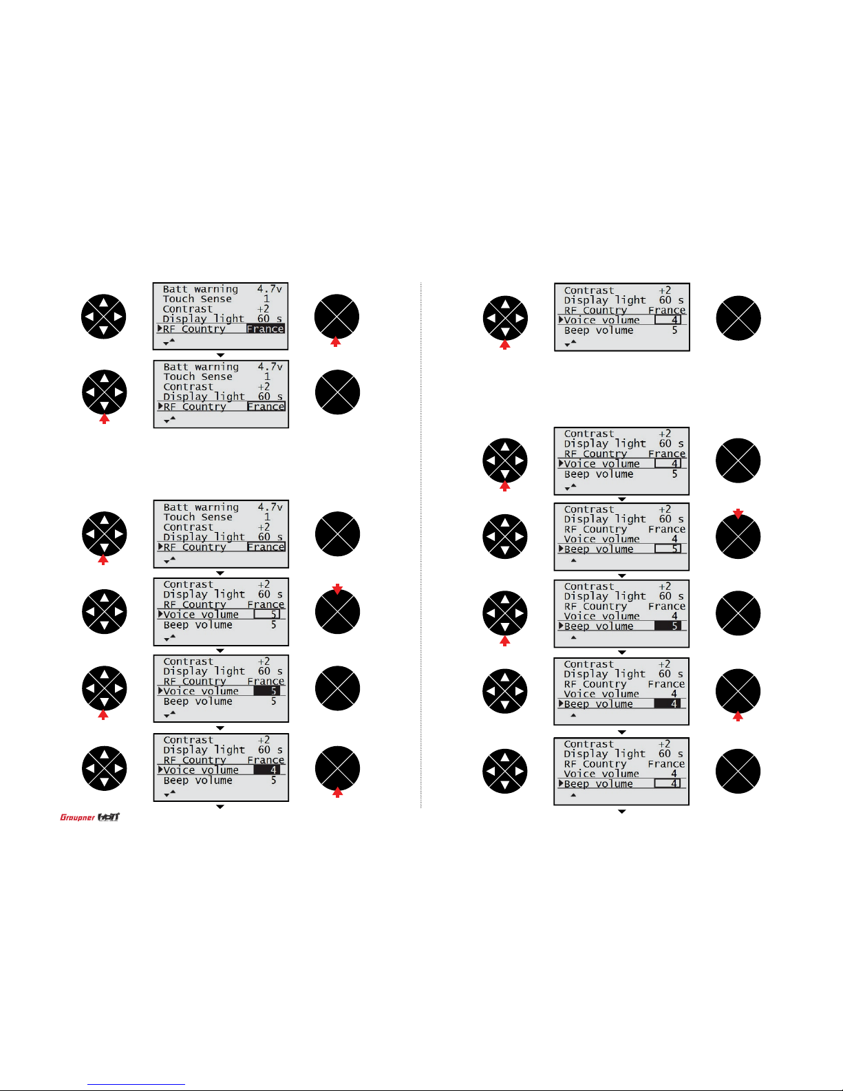
- Voice volume
The same method is used to access the function and adjust the value with Batt type
programming.
- Beep volume
The same method is used to access the function and adjust the value with Batt type
programming.
ENT
ESC
TEL VIW
ENT
ESC
TEL VIW
ENT
ESC
TEL VIW
ENT
ESC
TEL VIW
ENT
ESC
TEL VIW
ENT
ESC
TEL VIW
ENT
ESC
TEL VIW
ENT
ESC
TEL VIW
ENT
ESC
TEL VIW
ENT
ESC
TEL VIW
ENT
ESC
TEL VIW
press
press
ENT
ESC
TEL VIW
press
press
press
press
press
press
press
press
press
52
Page 53

12. Fail safe (AIRCRAFR and Helicopter)
- Hold
If you lose connection between the transmitter and the receiver, all channels hold the last
given command.
- F/S
If the signal is lost, all channels are driven to their failsafe preset position during binding.
Press the direction button to highlight the fail safe then press the ENT button to access
the function. The black dot is on the NO.1 channel indicating NO.1 channel is selected
and the Hold (the default mode) is assigned. Press the direction button to select the
channel and press the ENT button to select the F/S or the hold. After completing to select
the desired mode in all channels, press the direction button to select the Delay. Press the
ENT button to highlight the value then press the direction button to adjust the desired value. Press the ESC button to highlight the STO. Move the stick to the desired position then
press the ENT button. The popup message “position stored” appears (the F/S function
is operated at that stick position). Conrm the failsafe setting is correct by turning off the
transmitter.
ENT
ESC
TEL VIW
ENT
ESC
TEL VIW
ENT
ESC
TEL VIW
ENT
ESC
TEL VIW
ENT
ESC
TEL VIW
press
press
press
ENT
ESC
TEL VIW
ENT
ESC
TEL VIW
press
press
press
When you bind your transmitter, you are programming the receiver with failsafe defaults.
If connection is lost between the transmitter and receiver, the receiver immediately operates in those preprogrammed default positions. Graupner receiver has 2 failsafe modes,
hold and Pos (Position/Fail Safe)
53
Page 54

13. Trainer (Aircraft and Helicopter)
The mz-12 has the trainer function. The function activates when you select Teacher, Pupil
and Normal mode. You may use this function by wireless and wired.
- The teacher mode programming setup
Press the direction button to highlight the teach pupil then press the ENT button to access
the function. The black dot is on the NO.1 channel indicating NO.1 channel is selected
and the T (Teacher/ the default mode) is assigned. Press the direction button to select the
channel and press the ENT button to select the T (Teacher) or –P (Pupil). After completing
to select the desired mode in all channels, press the direction button to select the hyphen.
Press the ENT button then the popup message “push desired switch into position on”
appears. Move the switch that you wish to use as the RF switch then the corresponding
value appears (The trainer function is on/off when that switch is moved). Press the direction
button to select the n/a in the BIND. The transmitter gets ready to bind to the pupil transmitter now.
54
ENT
ESC
TEL VIW
ENT
ESC
TEL VIW
ENT
ESC
TEL VIW
ENT
ESC
TEL VIW
ENT
ESC
TEL VIW
press
press
ENT
ESC
TEL VIW
ENT
ESC
TEL VIW
ENT
ESC
TEL VIW
ENT
ESC
TEL VIW
press
press
press
press
press
Page 55
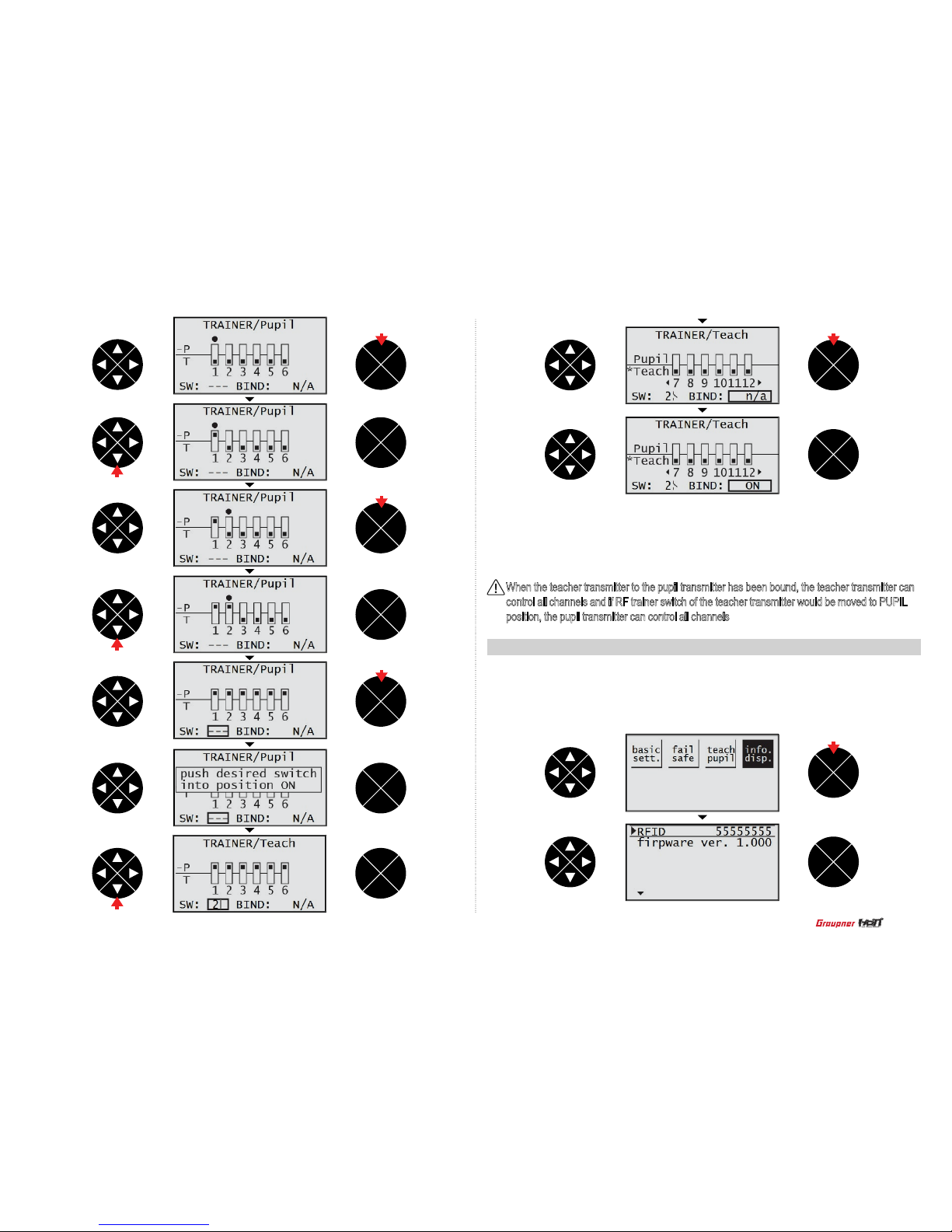
- The pupil mode programming setup
After selecting the n/a in the BIND, press the ENT button then bind to the teacher transmitter.
The pupil transmitter doesn’t need to program the other value.
14. Info disp (AIRCAFT and Helicopter)
RFID and rmware version information are displayed. Press the direction button to highlight
the info disp then press the ENT button to access the information, you can check the displayed
information.
55
ENT
ESC
TEL VIW
ENT
ESC
TEL VIW
ENT
ESC
TEL VIW
ENT
ESC
TEL VIW
ENT
ESC
TEL VIW
ENT
ESC
TEL VIW
ENT
ESC
TEL VIW
ENT
ESC
TEL VIW
ENT
ESC
TEL VIW
ENT
ESC
TEL VIW
ENT
ESC
TEL VIW
press
press
press
press
press
When the teacher transmitter to the pupil transmitter has been bound, the teacher transmitter can
control all channels and if RF trainer switch of the teacher transmitter would be moved to PUPIL
position, the pupil transmitter can control all channels
press
press
press
Page 56

This function is used to program receiver and telemetry sensor and get the data information
on them. This function can be accessed only if transmitter and receiver are bound. If not,
when the function is accessed, the error message “CAN’T RECIVE DATA OK” is appeared.
Press ENT button to access RX DATA VIEW, you may program and get the data information
on receiver data. If telemetry sensor is connected to receiver, you may also program and
get the data information on telemetry sensors.
This function allows you to get the data information on receiver.
16. SETTING & DATA VIEW
16-1. RX DATA VIEW
ENT
ESC
TEL VIW
ENT
ESC
TEL VIW
ENT
ESC
TEL VIW
ENT
ESC
TEL VIW
press
Telemetry is used to perform HoTT telemetry programming setup and check HoTT telemetry
data. 4 functions of SETTING & DATA VIEW, SENSOR SELECT, RF STATUS VIEW and
VOICE TRIGGER are available. Press TEL button to go to the start up page of telemetry.
SETTING & DATA VIEW has been selected on the star t up page. Whenever your press
DOWN button, 4 functions is selected in turn.
15. Telemetry
press
ENT
ESC
TEL VIW
ENT
ESC
TEL VIW
ENT
ESC
TEL VIW
ENT
ESC
TEL VIW
ENT
ESC
TEL VIW
press
press
press
56
Page 57

This function allows you to perform servo programming set up at the entries of OUTPUT
CH REVERSE, CENTER, TRIM, LIMIT-, LIMIT+, PERIOD. Press the direction button on
RX DATA VIEW mode to access to RX SERVO then press DOWN button to select the
desired article. Press ENT button to highlight the value on the selected article, you may
change to the desired value.
- OUTPUT CH
The receiver output channel can be selected. Press ENT button to highlight the value and
press UP/DOWN buttons to set the desired value. Press ENT button to remove the highlight.
16-2. RX SERVO
- REVERSE
It is used to decide the direction of servo rotation. Press DOWN button to access to REVERSE line then press ENT button to highlight the default value OFF. Press UP/DOWN button
to select ON or OFF. Press ENT button to remove the highlight.
ENT
ESC
TEL VIW
ENT
ESC
TEL VIW
ENT
ESC
TEL VIW
ENT
ESC
TEL VIW
ENT
ESC
TEL VIW
ENT
ESC
TEL VIW
ENT
ESC
TEL VIW
ENT
ESC
TEL VIW
ENT
ESC
TEL VIW
ENT
ESC
TEL VIW
press
press
press
press
press
press
ENT
ESC
TEL VIW
press
press
press
57
Page 58
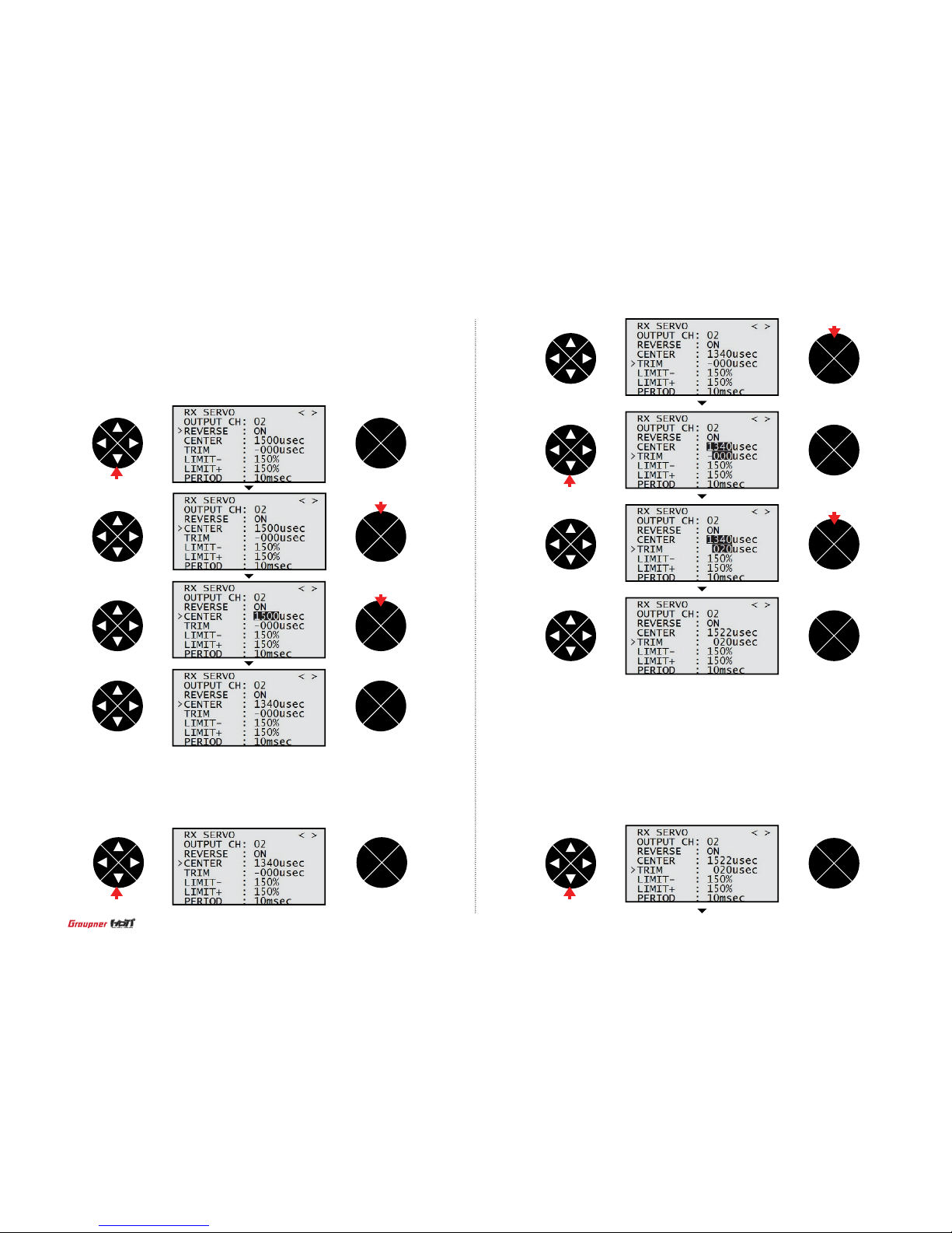
- LIMIT + / The maximum value for each direction can be programmed so that the maximum servo
travel limit of the connected servo is adjusted. The default value is 150% but the servo
travel range is limited to 100% that is programmed at SERVO EPA of transmitter so the
servo limit is not operated at 150% ~ 100%, but operated at below 100%. If SERVO EPA of
transmitter is set to 150%, the LIMIT value can be set below 150%. Press DOWN button to
access to LIMIT+/- line then press ENT button to highlight the default value 150%.
Press UP/DOWN button to program the desired value and then press ENT button to remove
the highlight.
ENT
ESC
TEL VIW
ENT
ESC
TEL VIW
ENT
ESC
TEL VIW
ENT
ESC
TEL VIW
ENT
ESC
TEL VIW
press
press
- CENTER
The value of servo center in the selected channel at OUTPUT CH can be programmed. The
center value depends on transmitter throttle and trim position. General servo center value is
1500us. Press DOWN button to access to CENTER line then press ENT button to highlight
the default value 1500usec. Move and hold transmitter throttle at the desired position then
press ENT button, the center value corresponding to throttle position is set.
- TRIM
the servo trim can be set. Press DOWN button to access to TRIM entry then press ENT
button to highlight the default value - 000usec. Press UP/DOWN button to program the desired
value and then press ENT button to remove the highlight.
ENT
ESC
TEL VIW
ENT
ESC
TEL VIW
ENT
ESC
TEL VIW
ENT
ESC
TEL VIW
ENT
ESC
TEL VIW
press
press
press
press press
press
58
Page 59
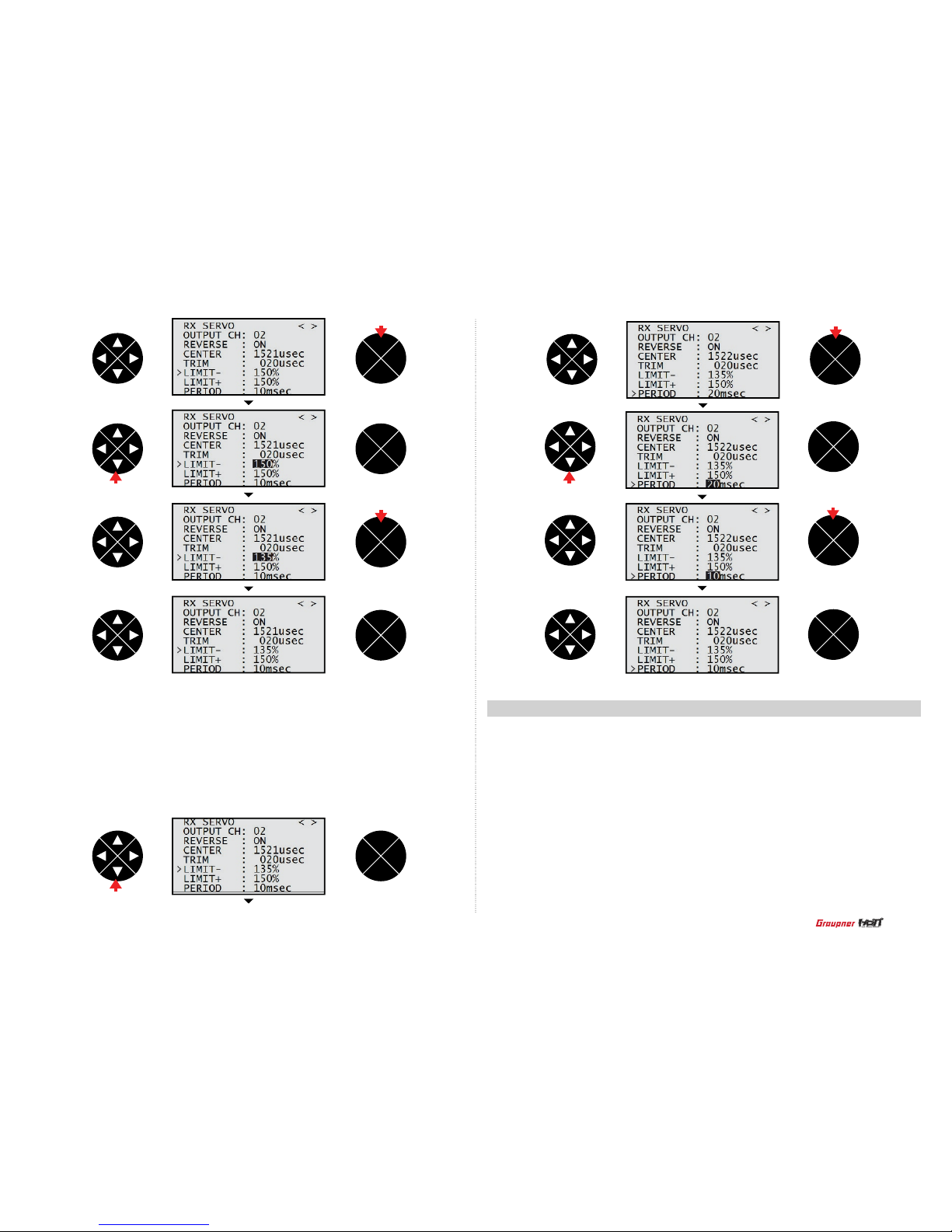
- PERIOD
The servo response time for transmitter throttle can be adjusted. All channels that servo
connected are applied separately. Press DOWN button to access to PERIOD line then
press ENT button to highlight the default value 20msec. Press UP/DOWN button to set
10msec or 20msec and then press ENT button to remove the highlight.
OUTPUT CH (receiver)/ INPUT CH (transmitter): It is used to perform the programming
setup of transmitter channel that is bound to receiver. The default setup is that each channel
1,2,3,4,5,6 of receiver is connected to the same channel 1,2,3,4,5,6 of transmitter. In case that
R16, 16 channel receiver, is bound to mz-12, 6 channel transmitter, this function is very useful.
For example, 4 aile, 4 ap are used in aircraft, 1~4 channels can be set to aile and 5~8 channels can be set to ap and then other channels can be set to elev or rudd. Press the direction
button at EX SERVO mode to go to RX FAIL SAFE mode. OUTPUT CH line has been selected
at RX FAIL SAFE mode. Press ENT button to highlight the default value 1. Press UP/DOWN
button to select the desired channel and then press ENT button to remove the highlight. Press
DOWN button to access to INPUT CH line. Press ENT button to highlight the default value 1.
Press UP/DOWN button to select the desired channel that is connected INPUT CH and then
press ENT button to remove the highlight.
16-3. RX FAIL SAFE
ENT
ESC
TEL VIW
ENT
ESC
TEL VIW
ENT
ESC
TEL VIW
ENT
ESC
TEL VIW
ENT
ESC
TEL VIW
ENT
ESC
TEL VIW
ENT
ESC
TEL VIW
ENT
ESC
TEL VIW
ENT
ESC
TEL VIW
press
press
press
press
press
press press
59
Page 60

- MODE
It is failsafe mode and HOLD/ FAIL SAFE/ HOLD are available.
Press DOWN button to access to MODE line then press ENT button to highlight the default
value HOLD. Press UP/DOWN button to select the desired value then press ENT button to
remove the highlight.
ENT
ESC
TEL VIW
ENT
ESC
TEL VIW
ENT
ESC
TEL VIW
ENT
ESC
TEL VIW
ENT
ESC
TEL VIW
press
press
ENT
ESC
TEL VIW
ENT
ESC
TEL VIW
ENT
ESC
TEL VIW
ENT
ESC
TEL VIW
ENT
ESC
TEL VIW
ENT
ESC
TEL VIW
press
press
press
press
press
press
press
60
Page 61

- F.S.POS.
It is used to set fail safe position at the desired channel that you select on OUTPUT CH.
Press DOWN button to access to F.S. Pos line then press ENT button to highlight the
default value 1500usec. Press UP/DOWN button to select the desired value then press
ENT button to remove the highlight.
- DELAY
This function allows you to set the time that failsafe takes to start under failsafe situation
Press DOWN button to access to DELAY line then press ENT button to highlight the default
value 0.75sec. Press UP/DOWN button to select the desired value then press ENT button to
remove the highlight.
ENT
ESC
TEL VIW
ENT
ESC
TEL VIW
ENT
ESC
TEL VIW
ENT
ESC
TEL VIW
ENT
ESC
TEL VIW
ENT
ESC
TEL VIW
ENT
ESC
TEL VIW
ENT
ESC
TEL VIW
ENT
ESC
TEL VIW
press
press
press
press
ENT
ESC
TEL VIW
presspress
press
press
61
Page 62
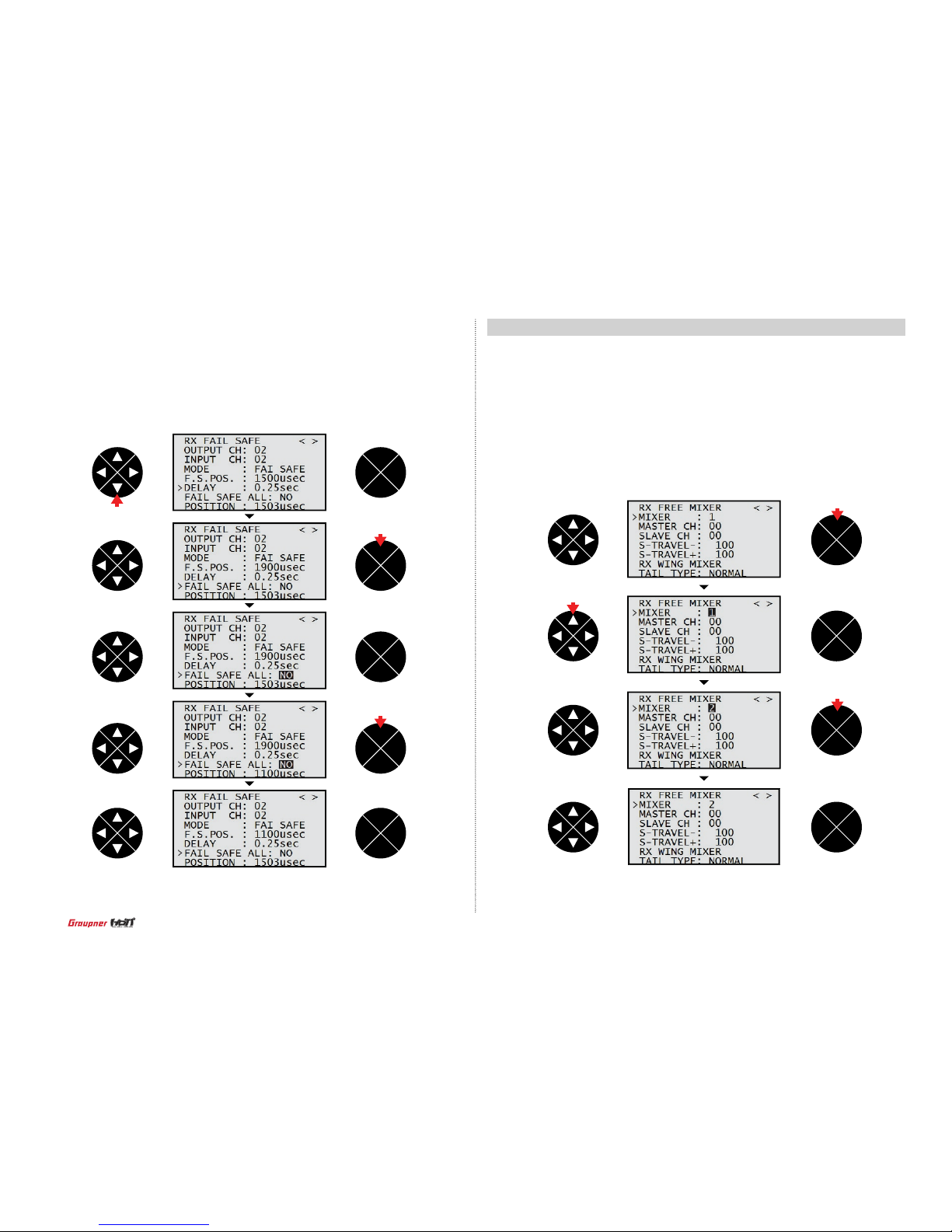
This function allows you to perform the FREE MIXER programming setup.
- MIXER
It is use to select the mixer number that you want to use
Press ENT button to highlight the default value 1 then press UP/DOWN button to select
the desired channel. Press ENT button to remove the highlight. 5 mixers from 1 to 5 are
available.
16-4. RX FREE MIXER
ENT
ESC
TEL VIW
ENT
ESC
TEL VIW
ENT
ESC
TEL VIW
ENT
ESC
TEL VIW
press
press
press
- POSITION
It indicates the operating range of throttle at OUTPUT CH.
ENT
ESC
TEL VIW
- FAIL SAFE ALL
It is used when you change failsafe position value of all channels. You need set all channels to
FAIL SAFE to use this function.
Press DOWN button to access to FAIL SAFE ALL line then press ENT button to highlight the
default value NO. Move and hold transmitter throttle at the desired position then press ENT
button, the failsafe value corresponding to throttle position is set. After setup FAIL SAFE ALL,
if you need to check whether the fail safe function is normal worked, turn off both of transmitter
and receiver’s power then servos should be operated to the preset failsafe.
ENT
ESC
TEL VIW
ENT
ESC
TEL VIW
ENT
TEL VIW
ENT
ESC
TEL VIW
press
press
press
62
Page 63
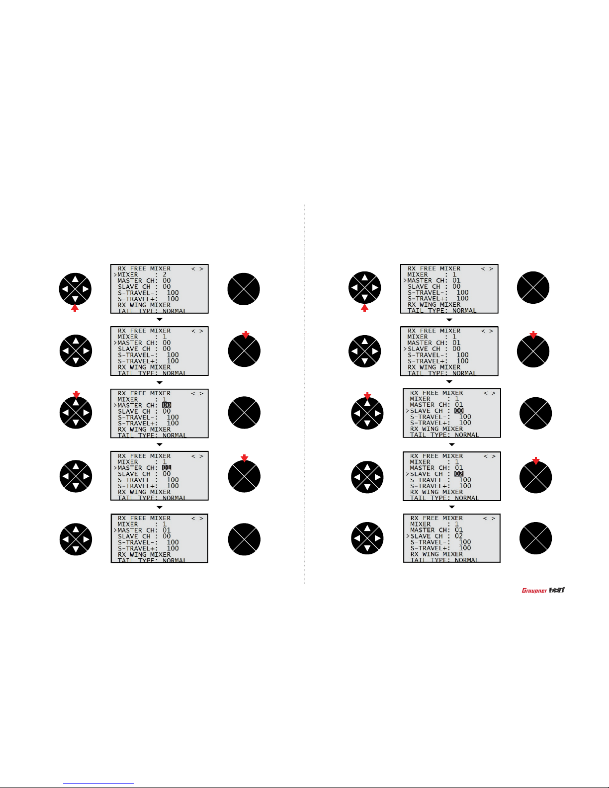
- MASTER CH
Master CH in FREE MIXER can be selected.
Press DOWN button to access to MASTER CH line then press ENT button to highlight
the default value 00. Press UP/DOWN button to select the desired channel then press
ENT button to remove the highlight.
- SLAVE CH
Slave CH in FREE MIXER can be selected.
Press DOWN button to access to SLAVE CH line then press ENT button to highlight the
default value 00. Press UP/DOWN button to select the desired channel then press ENT
button to remove the highlight.
ENT
ESC
TEL VIW
ENT
ESC
TEL VIW
ENT
ESC
TEL VIW
ENT
ESC
TEL VIW
ENT
ESC
TEL VIW
ENT
ESC
TEL VIW
ENT
ESC
TEL VIW
ENT
ESC
TEL VIW
ENT
ESC
TEL VIW
ENT
ESC
TEL VIW
press
press
press
press
press
press
press press
63
Page 64
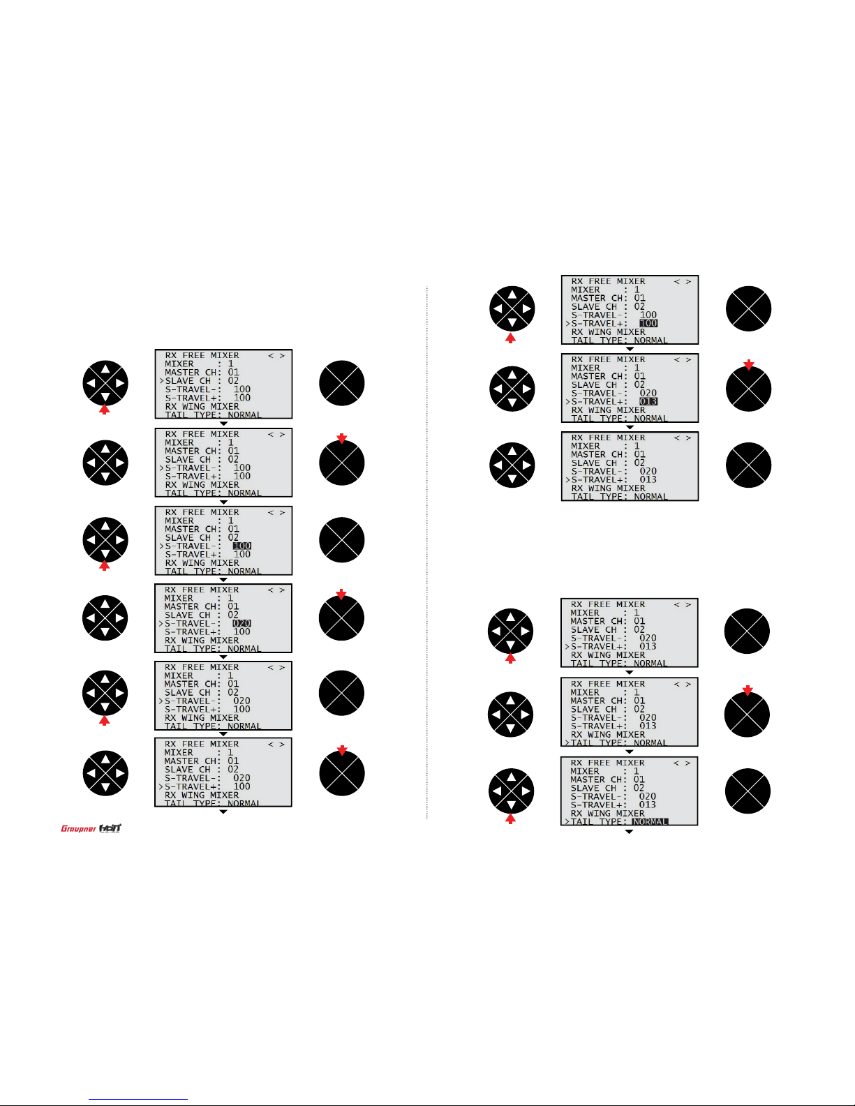
- RX WING MIXER TAIL TYPE
This function is used to set the proper tail type. You may select one type of Normal,
V-Tail, Elevon can be selected depending on the model type. Press DOWN button to
access to RX WING MIXER TAIL TYPE line then press ENT button to highlight the
default value NORMAL. Press UP/DOWN button to select the desired type then press
ENT button to remove the highlight.
ENT
ESC
TEL VIW
ENT
ESC
TEL VIW
ENT
ESC
TEL VIW
press
ENT
ESC
TEL VIW
ENT
ESC
TEL VIW
ENT
ESC
TEL VIW
press
ENT
ESC
TEL VIW
ENT
ESC
TEL VIW
press
ENT
ESC
TEL VIW
press
- S-TRAVEL + / The maximum servo travel that is connected to slave channel can be programmed.
Press DOWN button to access to S- TR AVEL+/- line then press ENT button to highlight the
default value 00. Press UP/DOWN button to select the desired channel then press ENT
button to remove the highlight.
ENT
ESC
TEL VIW
ENT
ESC
TEL VIW
ENT
ESC
TEL VIW
press
press
press
press
press
press
press
64
Page 65

16-5. RX CURVE
Perform the exponential programming setup at R X CURVE mode. You may program
the exponential value of channel 2,3,4. The default setup is B curve that leads Servo
responds proportionally depending on transmitter throttle movement. A curve leads that
Servo responds sensitively and C curve leads that Servo responds softly.
Press ENT button to access to highlight the default channel 20 on CURVE 1 CH line
then press UP/DOWN buttons to select the desired channel. The default setup is CH2
AILE, CH3 ELEV, CH4 RUDD. Press ENT button to remove the highlight and press UP/
DOWN button to access TYPE line. Press ENT button to highlight the default value B
then press UP/DOWN buttons to select one of A, B, C. CURVE2 and 2 can be set in the
same method with CURVE1.
ENT
ESC
TEL VIW
ENT
ESC
TEL VIW
ENT
ESC
TEL VIW
ENT
ESC
TEL VIW
ENT
ESC
TEL VIW
press
ENT
ESC
TEL VIW
press
ENT
ESC
TEL VIW
ENT
ESC
TEL VIW
press
press
ENT
ESC
TEL VIW
press
ENT
ESC
TEL VIW
press
ENT
ESC
TEL VIW
press
press
press
65
Page 66
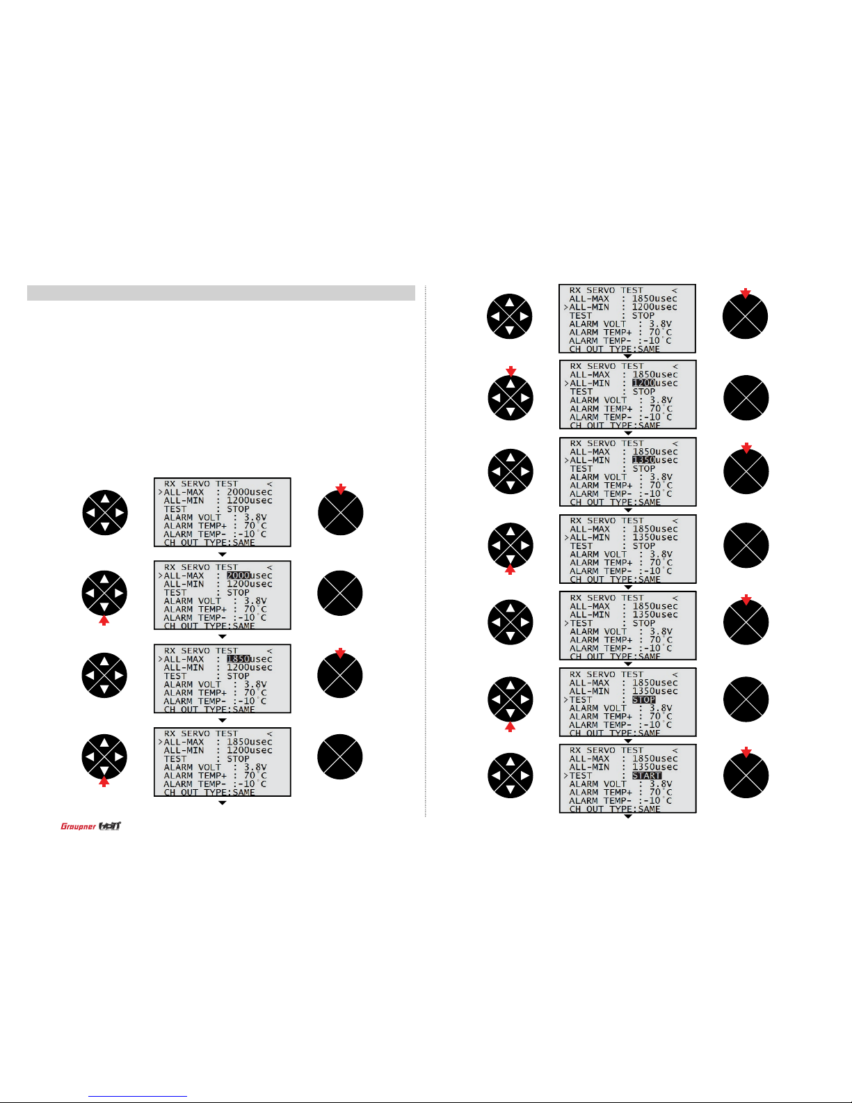
ENT
ESC
TEL VIW
ENT
ESC
TEL VIW
press
ENT
ESC
TEL VIW
press
ENT
ESC
TEL VIW
press
ENT
ESC
TEL VIW
press
ENT
ESC
TEL VIW
press
ENT
ESC
TEL VIW
ENT
ESC
TEL VIW
ENT
ESC
TEL VIW
ENT
ESC
TEL VIW
press
16-6. RX SERVO TEST
It used to perform servo test and program the voltage of receiver power, the max/min
temperature of receiver CH OUT TYPE of receiver. Press UP/DOWN buttons to select the
desired line and press ENT button then the default value is highlighted. Press UP/DOWN
buttons to set the desired value and press ENT button to remove the highlight.
- ALL MAX
The maximum servo travel can be decided for servo test
- ALL Min
The minimum servo travel can be decided for servo test
- TEST
You may start or stop servo test
ENT
ESC
TEL VIW
press
press
press
press
press
66
Page 67
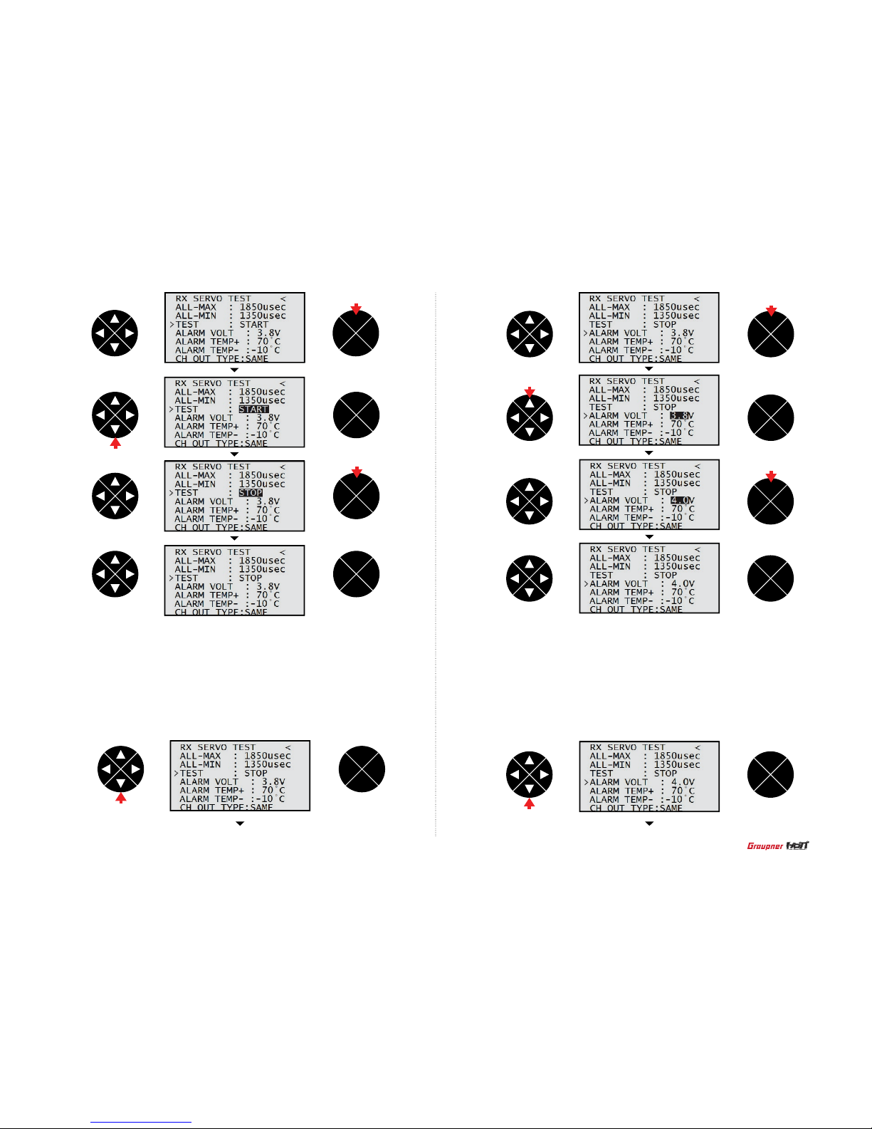
- ALARM VOLT : Low voltage warning
If receiver voltage is out of the preset voltage, transmitter repeats a beep warning.
Press DOWN buttons to access to ALARM VOLT and press ENT button then the default
value 3.8V is highlighted. Press UP/DOWN buttons to set the desired value and press
ENT button to remove the highlight.
- ALARM TEMP + / - : Temperature warning
If receiver temperature is out of the preset temperature, transmitter repeats a beep warning.
Press DOWN buttons to access to ALARM TEMP and press ENT button then the default
value is highlighted. Press UP/DOWN buttons to set the desired value and press ENT button
to remove the highlight.
ENT
ESC
TEL VIW
ENT
ESC
TEL VIW
ENT
ESC
TEL VIW
ENT
ESC
TEL VIW
press
ENT
ESC
TEL VIW
press
ENT
ESC
TEL VIW
ENT
ESC
TEL VIW
press
ENT
ESC
TEL VIW
press
ENT
ESC
TEL VIW
press
ENT
ESC
TEL VIW
press
press
press
67
Page 68

ENT
ESC
TEL VIW
ENT
ESC
TEL VIW
press
CH OUT TYPE
You may decide the signal output type of receiver. 5 types of ONCE / SAME / SUMO12/
SUMI / SUMD HD12 are available.
- ONCE
It is use for analogue servo. If ONCE is selected, PERIOD on RX SERVO is set to
20msec automatically.
- SAME
It is use for digital servo. If SAME is selected on CH OUT TYPE line, you need to set
PERIOD on R X SERVO to 10 ~ 20msec. when analogue servo is used, 20mse should
be set.
- SUMI
Receiver get the signal of the receiver performed the SUMO programming setup then
outputs the signal
- SUMD HD
The digital output signal of all channels in receiver is outputted from the selected channel.
It is used to the product that needs the receiver digital signal such as Power box and Flybarless system. The factory default for SUMD HD output channel is the last channel of receiver
and you may change it.
- SUMO
Only the selected channel outputs the signal of all channels of receiver. In case that 1
receiver is set to SUMO and the other receiver is set to SUMI and then they are connected in ex code, the receiver set to SUMI outputs the signal came from the receiver set to
SUMO. The nal channel of receiver is set to SUMO output channel, but you may change
to the desired channel.
Press DOWN buttons to access CH OUTPUT TYPE and press ENT button then the
default value SAME is highlighted. Press UP/DOWN buttons to set the desired value and
press ENT button to remove the highlight. When you select SUMO 12 and SUMD HD12
and tr y to select the different output channel, press ENT button to move the highlight to 12
then press UP/DOWN button to select the desired channel. Press ENT button to remove
the highlight.
ENT
ESC
TEL VIW
press
ENT
ESC
TEL VIW
ENT
ESC
TEL VIW
press
ENT
ESC
TEL VIW
press
ENT
ESC
TEL VIW
press
ENT
ESC
TEL VIW
press
press
68
Page 69

It is used to program telemetry sensor that is connected to HoTT receiver. The sensor
should be connected to the telemetry pin of receiver to use voice function, warning and
the telemetr y data information.
Press DOWN buttons to go to SENSOR SELECT line and press ENT button to access the
function. Press DOWN button to select one of RECEIVER, GENERAL MODULE, ELECTRIC AIR.MOD, VARIO MODULE, GPS, ESC and press ENT button to mark the box. The
marked function is activated.
17. SENSOR SELECT
ENT
ESC
TEL VIW
ENT
ESC
TEL VIW
ENT
ESC
TEL VIW
ENT
ESC
TEL VIW
ENT
ESC
TEL VIW
ENT
ESC
TEL VIW
ENT
ESC
TEL VIW
ENT
ESC
TEL VIW
press
press
ENT
ESC
TEL VIW
press
ENT
ESC
TEL VIW
ENT
ESC
TEL VIW
press
press
press
press
press
press
press
69
Page 70

It is used to program the sensors related with voice function. The default article
REPEAT, TRIG, VARIO, TRANSSMITTER, RECEIVER are available and the optional
sensors could be attached. If the optional sensor is connected, it is need to add the
function for the optional sensor at SENSOR SELECT mode then VOICE TRIGGER
article is created. The useable sensors are GENERAL MODULE, ELECTRIC AIR MOD ULE, VARIO MODULE, GPS, AIR ESC.
- REPEAT
You may set the time and switch and if the switch is on, one of voice functions is
repeated for the setting time. Press DOWN buttons to go to VOICE TRIGGER line and
press ENT button then the default value 10sec on REPEAT is highlighted. Press UP/
DOWN buttons to set the desired value and press ENT button to remove the highlight.
Press the direction button to highlight the hyphen mark then press ENT button. The
popup message “push desired switch into position on” is appeared. Operate the switch
to be used as REPEAT on/off, that switch is designated as REPEAT on/off. After all
process, REPEAT function is operated when the switch is on.
19. VOICE TRIGGER
ENT
ESC
TEL VIW
ENT
ESC
TEL VIW
ENT
ESC
TEL VIW
press
It shows RF status between transmitter and receiver through telemetr y function.
Press DOWN button to go to RF STATUS VIEW line and press ENT button to access to RF
STATUS VIEW mode. You may check RF status at this screen.
ENT
ESC
TEL VIW
18. RF STATUS VIEW
ENT
ESC
TEL VIW
ENT
ESC
TEL VIW
ENT
ESC
TEL VIW
press
ENT
ESC
TEL VIW
press
press
press
press
70
Page 71

- TRIG
You may designate the switch for the voice functions of transmitter and receiver and
the voice functions are changed in turn whenever the switch is on/off. Press DOWN
buttons to access to TRIG and press ENT button then the popup message “push desired switch into position on” is appeared. Operate the switch to be used as TRIG on/
off, that switch is designated as TRIG on/off. After all process, the next voice function
is accessed whenever the switch is on.
If the switch that has spring such as S2 is designated as TRIG switch, on/off function
is operated simultaneously so it is very convenient.
ENT
ESC
TEL VIW
ENT
ESC
TEL VIW
ENT
ESC
TEL VIW
ENT
ESC
TEL VIW
press
ENT
ESC
TEL VIW
press
ENT
ESC
TEL VIW
press
ENT
ESC
TEL VIW
ENT
ESC
TEL VIW
ENT
ESC
TEL VIW
press
ENT
ESC
TEL VIW
ENT
ESC
TEL VIW
press
ENT
ESC
TEL VIW
press
press
press
71
Page 72

- TRANSMITTER
You may program the telemetry voice function of transmitter, TX VOLT, BATTERY TIME,
STOPWATCH, RUNTIME, Press DOWN buttons to go to TRANSMITTER line and press
ENT button to access TRANSMITTER setup mode. All voice function of TX VOLT, BATTERY TIME, STOPWATCH, RUNTIME have been set to use. Press the direction button
to select the desired line and press ENT button to unmark the box if you don’t want to
use voice function for the desired line.
ENT
ESC
TEL VIW
ENT
ESC
TEL VIW
ENT
ESC
TEL VIW
press
ENT
ESC
TEL VIW
press
ENT
ESC
TEL VIW
ENT
ESC
TEL VIW
ENT
ESC
TEL VIW
press
ENT
ESC
TEL VIW
ENT
ESC
TEL VIW
- VARIO
You may set the on/off switch of vario module for voice function.
Press DOWN buttons to access to VARIO and press ENT button then the popup message
“push desired switch into position on” is appeared. Operate the switch to be used as VARIO
on/off, that switch is designated as VARIO on/off. Voice function is operated when the switch
is on.
press
press
press
72
Page 73

- If the optional sensors are attached, the telemetry voice functions of an attached optional sensors can be programmed. It is need to add the function for the optional sensor at
SENSOR SELECT mode then VOICE TRIGGER article is created. Below is the example that
VOICE TRIGGER article is created.
Press the direction button on transmitter home screen to go to receiver telemetry screen.
Connect the optional sensors to receiver then press UP/DOWN button to check and program the desired optional sensors.
20. The Programming Setup For Telemetry Sensors
ENT
ESC
TEL VIW
ENT
ESC
TEL VIW
ENT
ESC
TEL VIW
ENT
ESC
TEL VIW
- RECEIVER
You may program the telemetry voice function of receiver, TEMP, STRENGTH, RX
VOLT, LOWVOLT, Press DOWN buttons to go to RECEIVER line and press ENT button
to access to RECEIVER setup mode. All voice function of TEMP, STRENGTH, RX VOLT,
LOWVOLT have been set to use. Press the direction button to select the desired line
and press ENT button to unmark the box if you don’t want to use voice function for the
desired line.
ENT
ESC
TEL VIW
ENT
ESC
TEL VIW
press
ENT
ESC
TEL VIW
ENT
ESC
TEL VIW
ENT
ESC
TEL VIW
press
press
press
press
73
Page 74

ENT
ESC
TEL VIW
ENT
ESC
TEL VIW
ENT
ESC
TEL VIW
ENT
ESC
TEL VIW
ENT
ESC
TEL VIW
ENT
ESC
TEL VIW
ENT
ESC
TEL VIW
ENT
ESC
TEL VIW
ENT
ESC
TEL VIW
ENT
ESC
TEL VIW
ENT
ESC
TEL VIW
ENT
ESC
TEL VIW
press
press
press
press
press
press
press
press
74
Page 75
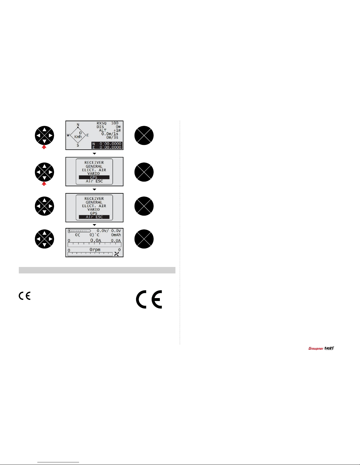
ENT
ESC
TEL VIW
ENT
ESC
TEL VIW
ENT
ESC
TEL VIW
ENT
ESC
TEL VIW
press
press
•
Safety Approval
EN 62479:2010
EN 60950-1:2006/A11:2009/A1:2010/A12:2011
EN 301 489-1 V1.9.2
EN 301-489-17 V2.2.1
EN 300 328 V1.7.1
• FCC Information
Product(s) :
Graupner mz-12 Transmitter
Contains FCC ID: SNL-36204210
FCC 47 CFR PART 15B
Product(s) : Graupner HoTT GR-16(L) (8 channels) Receiver
FCC ID :
ZKZ-33508
FCC 47 CFR PART 15C
•
FCC Statement
1. This device complies with Part 15 of the FCC Rules. Operation is subject to the following
two conditions:
(1) This device may not cause harmful interference.
(2) This device must accept any interference received, including interference that may cause
undesired operation.
2. Changes or modications not expressly approved by the party responsible for compliance
could void the user‘s authority to operate the equipment.
Declaration of Conformity
(in accordance with ISO/IEC 17050-1)
0678
Product(s):
Graupner mz-12 Transmitter
Item Number(s):
Equipment class: 2
The objects of declaration described above are in conformity with the requirements of
the specications listed below, following the provisions of the European R&TTE directive
1999/5/EC:
75
Page 76

76
•
Caution
- This equipment’s aerial must be at least 20 cm from any person when the system is in use.
We therefore do not recommend using the equipment at a closer range than 20cm.
- Ensure that no other transmitter is closer than 20cm from your equipment, in order to avoid
adverse effects on the system’s electrical characteristics and radiation pattern.
- The radio control system should not be operated until the Country setting has been set
correctly at the transmitter. This is essential in order to fulll the requirements of various
directives - FCC, ETSI, CE, KC and etc. Please refer to the instructions for your particular
transmitter and receiver for details of this procedure.
- Check all working systems and carry out at least one full range check on the ground before
every ight, in order to show up any errors in the system and the models programming.
- Never make any changes to the programming of the transmitter or receiver whilst operating
a model.
•
ENVIRONMENTAL PROTECTION NOTES
This product must not be disposed of with other waste. Instead,
it is the user’s responsibility to their waste equipment by handing it
over to a designated collection point for the recycling of waste electrical
and electronic equipment. The separate collection and recycling of
your waste equipment at the time of disposal will help to conserve natural resources and
ensure that it is recycled in a manner that protects human health and the environment. For
more information about where you can drop off your waste equipment for recycling, please
contact your local city ofce, your household waste disposal service or where you purchased
the produce
•
NOTE
This equipment has been tested and found to comply with the limits for a Class B digital
device, pursuant to Part 15 of the FCC Rules. These limits are designed to provide reasonable
protection against harmful interference in a residential installation. This equipment generates
uses and can radiate radio frequency energy and, if not installed and used in accordance with
the instructions, may cause harmful interference to radio communications. However, there is
no guarantee that interference will not occur in a particular installation. If this equipment does
cause harmful interference to radio or television reception, which can be determined by turning
the equipment off and on, the user is encouraged to try to correct the interference by one or
more of the following measures:
- Reorient or relocate the receiving antenna.
- Increase the separation between the equipment and receiver.
- Connect the equipment into an outlet on a circuit different from that to which the receiver is
connected.
- Consult the dealer or an experienced radio/TV technician for help.
•
FCC radiation exposure statement
This equipment complies with FCC radiation exposure limits set forth for an uncontrolled
environment. This equipment should be installed and operated with minimum distance of 20 cm
between the radiator and your body.
•
KC Information
Product(s) :
Graupner mz-12 Transmitter
- KCC인증번호: KCC-RRM-sjr-16005100, KCC-CRM-sjr-36204210
- 방송통신위원회고시 제2013-01호 “무선설비규칙”
- 방송통신위원회고시 제2012-102호 “신고하지 아니하고 개설할 수 있는 무선기기”
-KN 301 489-1:2009
-KN 301 489-17:2009
-KN 61000-4-2:2008
-KN 61000-4-3:2011
Product(s) : Graupner HoTT GR-16(L) (8 channels) Receiver
- KCC인증번호: KCC-CRM-sjr-16003120
- 방송통신위원회고시 제2013-01호
- 방송통신위원회고시 제2012-102호 “신고하지 아니하고 개설할 수 있는 무선기기”
국립전파 연구원의 전자파 적합등록을 획득하였습니다.
(This product is certified and registered from Korean National Radio Research Agency.)
Page 77

mz-12
 Loading...