

Page 1
SERIAL DIGITAL I/O UPGRADE
Installation Manual
071-8074-00
NOVEMBER 2000
PROFILE FAMILY
VIDEO FILE SERVERS
Page 2

Copyright Copyright © 2000 Grass Valley Group Inc. All rights reserved. Printed in the United
States of America.
This document may not be copied in whole or in part, or otherwise reproduced
except as specifically permitted under U.S. copyright law, without the prior written
consent of Grass Valley Group Inc., P.O. Box 59900, Nevada City, California
95959-7900
Trademarks Grass Valley, GRASS VALLEY GROUP, Profile and Profile XP are either
registered trademarks or trademarks of Grass Valley Group in the United States
and/or other countries. Other trademarks used in this document are either
registered trademarks or trademarks of the manufacturers or vendors of the
associated products. Grass Valley Group products are covered by U.S. and foreign
patents, issued and pending. Additional information regarding
Grass Valley Group's trademarks and other proprietary rights may be f ound at
www.grassvalleygroup.com.
Disclaimer Product options and specifications subject to change without notice. The
information in this manual is furnished for informational use only, is subject to
change without notice, and should not be construed as a commitment by Grass
Valley Group. Grass Valley Group assumes no responsibility or liability for any
errors or inaccuracies that may appear in this publication.
U.S. Government
Restricted Rights
Legend
Use, duplication, or disclosure by the United States Government is subject to
restrictions as set forth in subparagraph (c)(1)(ii) of the Rights in Technical Data
and Computer Software clause at DFARS 252.277-7013 or in subparagraph c( 1)
and (2) of the Commercial Computer Software Rest ricted Rights clause at FAR
52.227-19, as applicable. Manufacturer is Grass Valley Group Inc., P.O. Box
59900, Nevada City, California 95959-7900 U.S.A.
Revision Status
Rev Date Description
December 1997 Original issue. Manual Part Number 070-9977-00.
November 2000 Revised Product Support contact information.
Part Number 071-8074-00.
Page 3

Grass Valley Group Product Support
You can get technical assistance, check on the status of problems, or report new
problems by contacting our Product Support Group.
United States and Canada
Monday–Friday 5:30AM–5:00PM Pacific Time
(800) 547-8949
Europe
Monday–Friday 9:00AM–5:30PM
France
Germany 49 221 1791 234 Other +44 1753 218 777
Italy 02 25086606
01 45 29 73 00
Asia and South America
Australia
- from overseas
Beijing 86-10-62351230
Brazil 55-11-3741-8422 Taiwan 886-2-27571571
Hong Kong 852-2585-6579
02-9888 0100
61-2-9888 0100
ext. 711
World Wide
24-hour Emergency Hotline (530) 478-4148 (Contract and warranty customers)
World Wide Web http://www.grassvalleygroup.com/support//
FTP Site ftp.grassvalleygroup.com
E-mail profile-users@grassvalleygroup.com
United Kingdom 01628 405830
Japan 81-3-3448-3111
Korea 82-2-528-5299
Mexico 52-5-666-6333
Singapore 65-356-3900
Serial Digi t al I/O Upgrade Installat ion iii
Page 4

General Safety Summary
Review the following safety precautions to avoid injury and
prevent damage to this product or any products connected to it.
Only qualified personnel should perform service procedures.
While using this product, you may need to acce ss other parts of the
system. Read the g eneral safety s ummary in other sys tem manuals
for warnings and cautions related to operating the system.
Injury Precautions
Do Not Operate
Without Product
Covers in Place
Do Not Operate in
Wet/Damp
Conditions
Do Not Operate in an
Explosive
Atmosphere
Avoid Exposed
Circuitry
To avoid electric shoc k or fire hazar d, do not o per ate t his pro duct
with covers or panels removed.
To avoid electric shock, do not opera te this product in wet or damp
conditions.
To avoid injury or fire hazard, do not operate this product in an
explosive atmosphere.
To avoid injury, remove jewelry such as ri ngs, watches, and other
metallic objects. Do not touch exposed connections and
components when power is present.
iv Serial Digital I/O Upgrade Installation
Page 5
Product Damage Precautions
Product Damage Precautions
Use the Proper
Voltage Setting
Provide Proper
Ventilation
Do Not Operate If
You Suspect
Product Failures
Ensure that the lin e selector is in the proper po sition for t he power
source before applying power.
Prevent product overheating by providing proper ventilation.
If you suspect there is damage to this pro duct, have it in spected by
qualified service personnel.
Safety Terms and Symbols
Terms in This
Manual
!
!
Terms on the
Product
These terms may appear in this manual:
WARNING: Warning statements id ent ify conditions or practic es
that can res ult in person al injury or loss of life.
CAUTION: Caution statements identify conditions or practices
that can result in damage to the equipment or other property.
These terms may appear on the product:
DANGER indicates a personal injury hazard immediately
accessible as one reads the marking.
WARNING indicates a personal injury hazard not immediately
accessible as you read the marking.
CAUTION indicates a hazard to property, including the product.
Serial Digi t al I/O Upgrade Installat ion v
Page 6
Symbols on the
Product
The following symbols may appear on the product:
DANGER high voltage
Protective ground (earth) terminal
!
ATTENTION – refer to manual
Service Safety Summary
!
Do Not Service
Alone
Disconnect Power To avoid electric shock, disconnect the main power by means of
Use Care When
Servicing With
Power On
WARNING: These instructions are for use by qualified service
personnel only. To avoid personal injury, do not perform any
servicing unless you are qualified to do so. Refer to all safety
summaries before performing service.
Do not perform internal service or adjustment of this product
unless another person capable of rendering first aid and
resuscitation is present.
the power cord or, if provided, the power switch.
Dangerous voltages or currents may exist in this product.
Disconnect power and remove battery (if applicable) before
removing protective panels, soldering, or replacing components.
To avoid electric shock, do not touch exposed connections.
vi Serial Digital I/O Upgrade Installation
Page 7

Certifications and Compliances
Certifications and Compliances
FCC Emission
Control
Canadian EMC
Notice of
Compliance
This equipment has been tested and found to comply with the
limits for a Cl as s A digital device, p ursuant to Part 15 of the FCC
Rules. These limits are de signed to provi de reas ona ble prot ecti on
against harmful interference when the equipment is operated in a
commercial environment . This equipment generates, uses, and can
radiate radio frequency energy and, if not installed and used in
accordance with the instruction manual, may cause harmful
interference to radio communications. Operation of this
equipment in a residential area is lik ely to cause harmful
interference in which case the user will be required to correct the
interference at his own expense. Changes or modifications not
expressly approved by Grass Valley Group can affect emission
compliance and could void the user’s authority to operate this
equipment.
This digital apparatus does not exceed the Clas s A limits for radio
noise emissions from digital apparatus set out in the Radio
Interference Regulations of the Canadian Department of
Communications.
Le présent appareil numérique n’émet pas de bruits radioélectriques
dépassant les limites applicables aux appareils numériques de la
classe A préscrites dans le R èglement sur le brouillage
radioélectrique édicté par le ministère des Communications du
Canada.
EN55022 Class A
Warning
For products that comply with Class A. In a domestic
environment, this produ ct ma y cause radio interferenc e, in which
case the user may be required to take adequate measures.
Serial Digi t al I/O Upgrade Installat ion vii
Page 8
Certification
Category Standard
Safety Designed/tested for compliance with:
UL1950 – Safety of Information Technology Equipment, including Electrical
Business Equipment (Third Edition, 1995)
IEC 950 – Safety of Information Technology Equipment, including Electrical
Business Equipm ent (Second edition, 1991)
CAN/CSA C22.2, No. 950- 95 – Safety of Information Technology Equipment,
including Electrical Business Equipment
EN60950 – Safety of Information Technology Equipment, including Electrical
Business Equipment (includes Appendix ZB)
viii Serial Digital I/O Upgrade Installation
Page 9

Serial Digital I/O Upgrade Installation
Introduction
These instructions explain how to install the new serial digital I/O board in a
PDR100 Video Disk Recorder or a PDR200 Video File Server. The latest boards
have Sharcnet connectors so that embedded audio can be routed to and from the
Audio Signal Processing Board (ASPB). These instructions also assume that you
have already installed a slave disk recorder board field upgrade. The slave board
converts a two-channel Profile system into a four-channel system.
NOTE: Embedded audio does not work wi th the Analog Audio I/ O boards that
came standard with the PDR100. You must install an ASPB in a PDR100 to
use embedded audio.
The instructions include procedures for:
• Opening the Profile chassis.
• Moving existing boards, if necessary, to make room for the new board.
• Installing the new board.
• Closing the Profile chassis.
• Verifying that the insta lled board is functionin g correctly.
System Requirements
The Profile system software installed in the Profile system must be version 2.1 or
higher. To check the software version installed in your Profile system, open the
VrdPanel application and cho ose
listed in the Product Version field in the displayed window.
Kit Contents
This upgrade kit includes the following:
• A serial digital component I/O board.
• Two Sharcnet cables.
• Two 50
• A set of stick-on identification labels.
• This installation manual.
Ω audio clock cables.
Help | About VdrPanel. The software version is
Serial Digi t al I/O Upgrade Installat ion 1
Page 10
Serial Digital I/O Upgrade Installation
Tools Required
Tools required, but not supplied, to install this kit are:
• A Torx tool with T10 and T15 tips.
• Electrostatic discharge (ESD) grounding straps.
Electrostatic Precautions
CAUTION: This product contains components that are highly sensitive to
!
!
electrostatic discharge. To protect these components from damage and to
maintain product reliability, take the following precautions whe n handling
the circuit boards:
• Handle all circuit boards in a static-protected area capable of controlling
static charge on conductive materials, people, and nonconductive
materials. Static-prot ected areas include nonstati c table tops and nonstatic
floor mats.
• Leave the board in its ESD static -shielded bag unt il you are re ady to install
the board.
• Wear ESD grounding straps when handling boards outside of their ESD
static-shielded bags.
• Handle the circuit boards only by the edges. Avoid touching the printed
wires on the back of the circuit board as much as possible.
2 Serial Digital I/O Upgrade Installation
Page 11
Installation Procedures
The procedures that follow take you step-by-step through the installation of the
serial digital I/O board. You can install the board with the Profile chassis fully
extended on the rack slides if the equipment rack is adequately anch ored to prevent
tipping, and if t her e is sufficient slack in the cables con nec ted to the rear panel t o
allow the chassis to fully extend on the slides.
If it is necessary for you to remove the Profile unit from the equipment rack to
perform this installation, refer to the Profile sy stem’s instal lation manual for
instructions.
WARNING: Unless the equipment rack is adequately anchored, the rack
!
could tip when the chassis is extended on the rack slides. To avoid possible
injury, make sure the rack is firmly secured before extending the chassis on
the rack slides.
Installation Procedures
Serial Digi t al I/O Upgrade Installat ion 3
Page 12

Serial Digital I/O Upgrade Installation
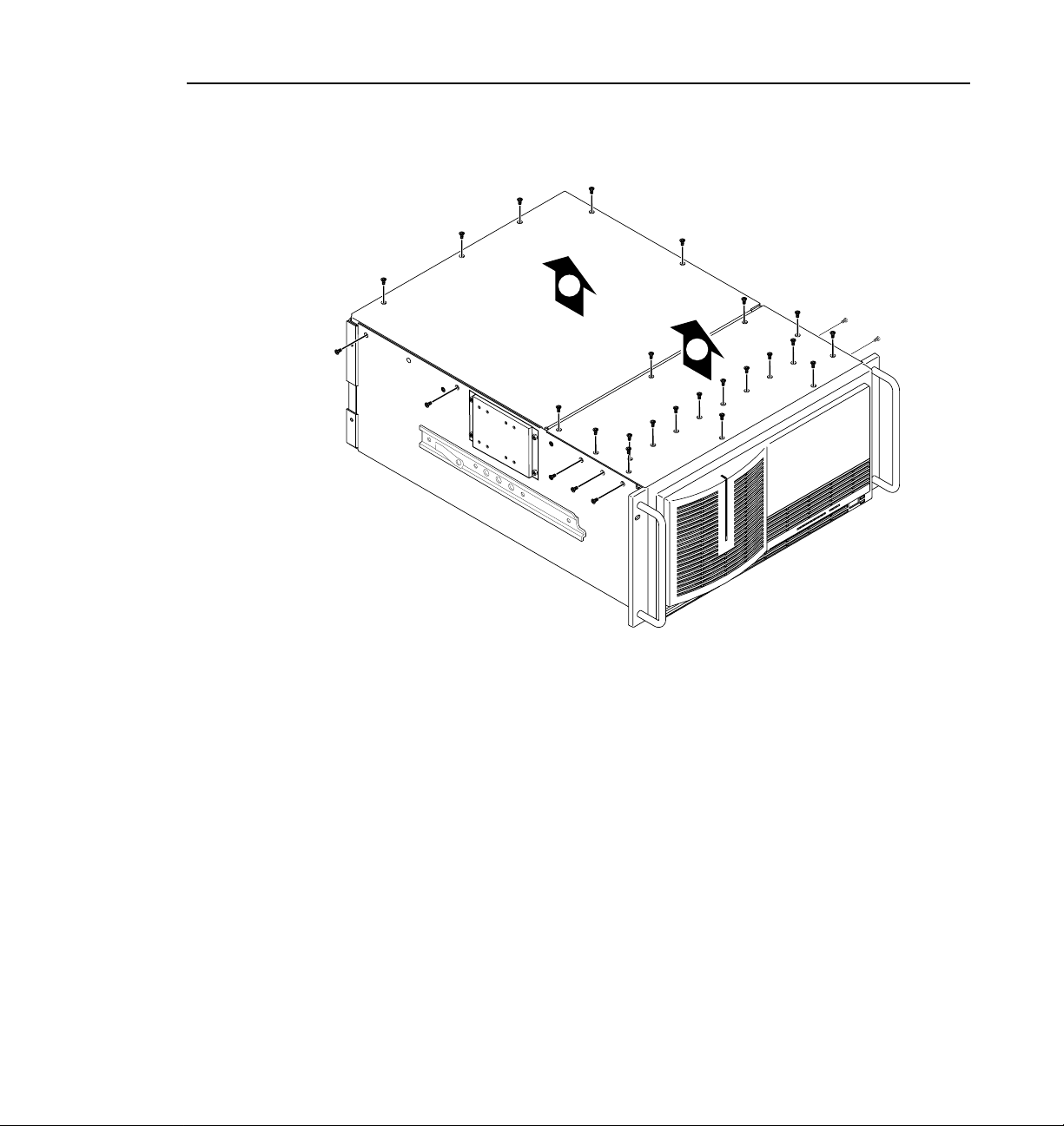
Removing the Chassis Covers
To remove the chassis covers:
1. Turn Profile system power off and remove the power cord.
2. Loosen the front pane l retaining s crew and pull the chassis out fr om the rack
until the slide sections latch. If the rack is not anchored firmly, remove the
chassis from the rack.
3. Use the T orx tool with the T10 tip to remove the top screws from the front
chassis cover (
screws.The front chas sis cover mus t be removed f irst because i t overlaps the
rear chassis cover (
NOTE: Take care not to lose these chassis screws. They are requi red to meet
the EMI specifications for the Profile unit. Also, not all the screws on a
PDR200, as shown in Figure 1, are present on a PDR100.
in Figure 1) and use the T15 tip to remove the side
Ê
in Figure 1).
Ë
4. Use the Torx tool with the T10 tip to remove the rear chassis cover (
Figure 1) which covers the circuit boards.
Ë
in
4 Serial Digital I/O Upgrade Installation
Page 13
9675-9
Removing the Chassis Covers
2
1
Figure 1. Removing the front and rear chassis covers
Serial Digi t al I/O Upgrade Installat ion 5
Page 14

Serial Digital I/O Upgrade Installation
Removing the Circuit Board Hold-down Brackets
There are two hold-down brackets located in the circuit board area that must be
removed in order to remove and replace circuit boards. Figure 2 shows these
brackets.
To remove the hold-down brackets:
1. Use the Torx tool with the T10 tip to remove the screw (
secures the rear board hold-down bracket.
2. Lift the hold-down bracket (
aside.
3. Use the Torx tool with the T10 tip to remove the screw (
secures the front board hold-down bracket.
4. Lift the hold-down bracket (
aside.
in Figure 2) up and out of t he ch assis and s et
Ë
in Figure 2) up and out of the chass is an d s et
Í
in Figure 2) which
Ê
in Figure 2) which
Ì
6 Serial Digital I/O Upgrade Installation
Page 15

Removing the Circuit Board Hold-down Brackets
3
4
2
9675-2
Figure 2. Removing the circuit board hold-down brackets
1
Serial Digi t al I/O Upgrade Installat ion 7
Page 16

Serial Digital I/O Upgrade Installation
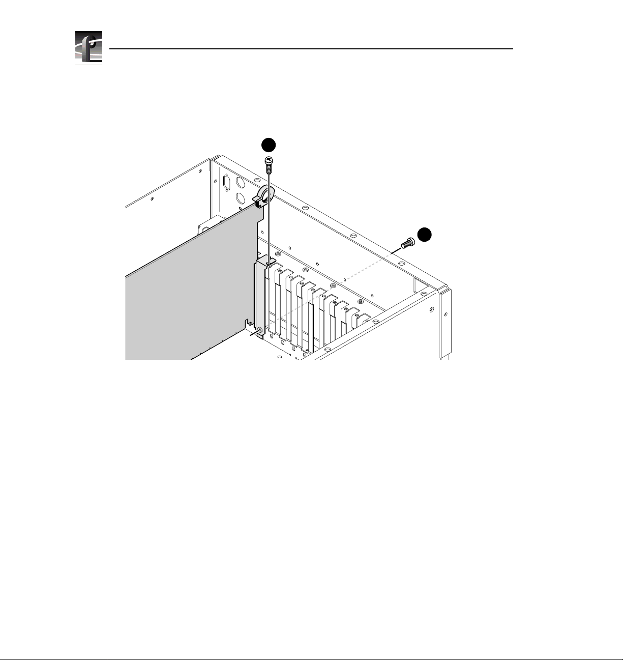
Removing Circuit Boards
Installing the serial digital I/O board may require that you remove or reposition
one or more currently insta lled board s to make room for the n ew board or to meet
internal cabling constraints.
When unplugging boards, you may also find it necessary to remove the screw
mounting an adjacent circuit board, and i n the case of shorter c ircuit boards, it may
be necessary to remove an adja cent tall ci rcuit board t o ease remova l of the short er
board.
Use the following procedure to unplug circuit boards from the motherboard:
1. Remove all interior and rear panel cables from the circuit boards that are to
be removed.
2. Use the Torx tool with the T15 tip to remove the screw from the bracket
inside the chassis (
outside the chassis (
CAUTION: To avoid damage to the circuit board when removing or
installing it:
in Figure 3) and the screw through the rear panel
Ê
in Figure 3).
Ë
- Do not rock the circuit boar d in the EISA bus connector — pull straight
up to remove.
- Do not grasp or push on the rear-panel connectors when removing or
installing circuit boards in the card slots.
3. Extract the circuit board. If the circuit board is tall, use the extraction lever
on the front of the board and the extraction ring at the back of the board to
lift the circuit board free of the connectors on the motherboard. For shorter
circuit boards, carefully grasp the board and lift upward to free the circuit
board from the motherboard connectors. You might need to remove an
adjacent tall board to get enough room for a safe hold on the shorter board.
8 Serial Digital I/O Upgrade Installation
Page 17

Removing Circuit Boards
1
Figure 3. Screw locations for board mounting bracket
2
9040-13
Serial Digi t al I/O Upgrade Installat ion 9
Page 18

Serial Digital I/O Upgrade Installation
Board Location Guide
This board location guide is provi ded to help you ins tall a serial dig ital I/O board
in a PDR200 or PDR100. The guide identifies t he video router inputs and outpu ts
of each Profile board currently available, as well as the input and output
connections on the video router connectors on the motherboard. Use this
information when:
• Adding a board to the Profil e system a nd selecting a s lot into whi ch you can
install it.
• Moving boards to meet requirements for new boards.
As you move boards, remember that some circuit boards must occupy specific
slots, while others can be installed in almost any slot as long as their I/O
requireme nts are met (see Table 1).
From the factory, a s ingle, two- channe l ser ial d igit al I/ O board comes inst alle d in
slot J14 in a PDR202D. The recommend ed slot for th e additional serial digi tal I/O
is slot J15, although it could be installed in any available slot from J5 to J15. In
order to use embedded audio , however, th e serial di gital I/ O boards must be clo se
enough to the Audio Signal Processing Board (ASPB) for the audio clock and
Sharcnet cables to reach. Also, the board must not be in a slot with shared inputs
when all the inputs are taken by the adjacent board, such as the four-channel
analog output board or the analog composite monitor board.
This section provi des a gen eral, simple a pproach t o board l ocation. It expl ains the
relationship between the motherboard and video router connectors and provides
tables, charts and examples to assist you in installing this and other boards.
Video Router to Motherboard Relationship
The video router provides and controls video data to twelve connectors on the
motherboard. These v ideo data con nectors are aligned wit h the main mothe rboard
connectors for slots J 5 through J16. Since the Reference Genlock (Re f Gen) board
must occupy J16 to provide t he necessar y system clo cks, this di scussion excludes
J16.
When choosing a slot for a board, the majo r constraint for a slot is how the board
connects to the vi deo ro uter. No t all boards requi re th e sa me number o f vide o I/O
connections, and n ot all video data connectors provide the same number of vi de o
I/O connections. Therefore, you must know how many input and output
connections the bo ard need s, if any, and the s lots availab le that me ets those needs.
10 Serial Digital I/O Upgrade Installa tion
Page 19

Board Location Guide
Board I/O Requirements and Restrictions
Table 1 lists each of the boards which may be installed in the Profile system and
the recommended slots, possible alternatives, and restrictions for each board. If
more than one slot is recommended or possible for a board, those slots are listed
in the order of preference.
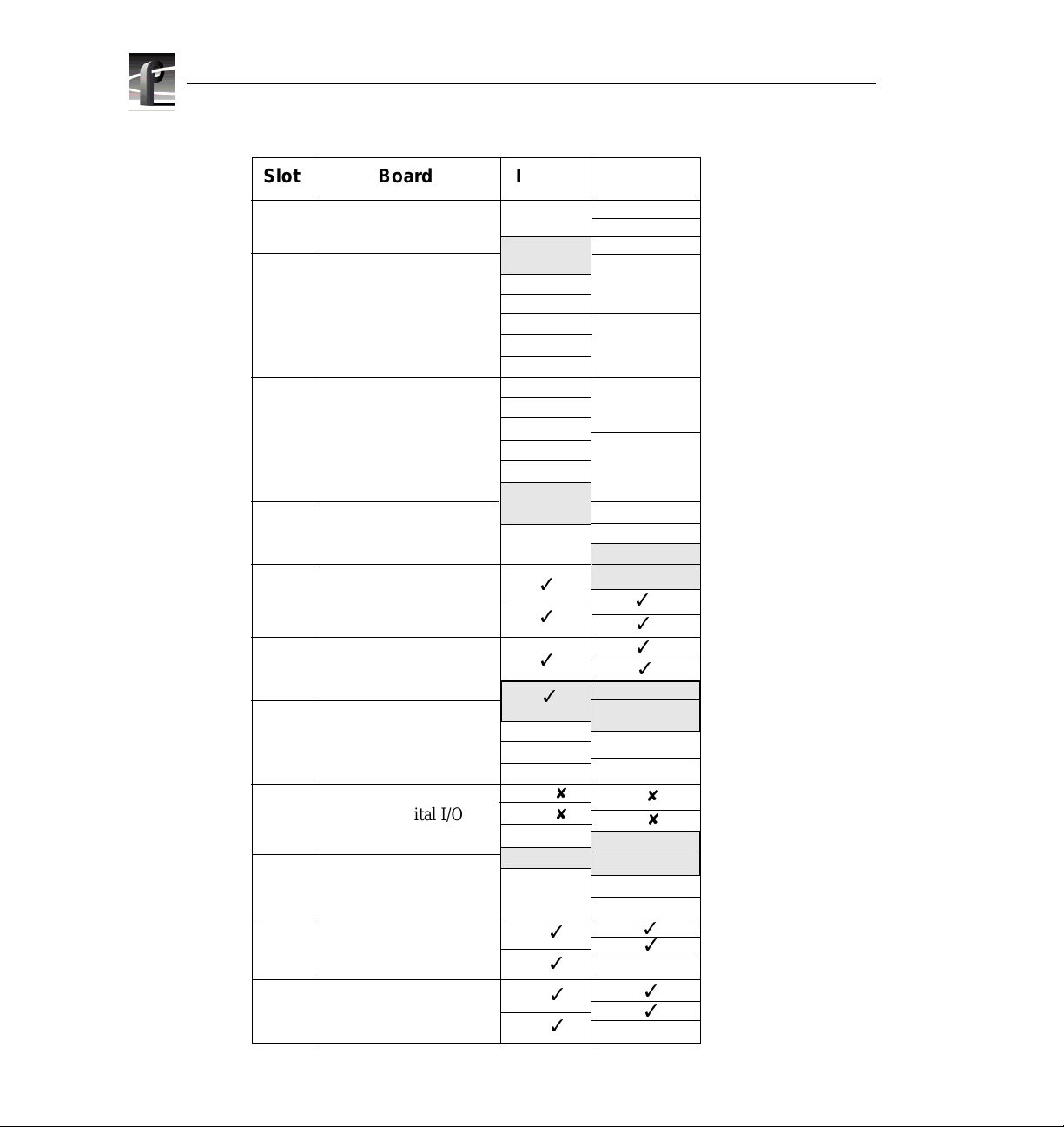
Video Router I/O Connections
Now let’s look at the vid eo router co nnections ava ilable at slots J5–J15. Table 2 is
a board location chart with the video router input and output connections. In this
table:
• The
Slot column lists each slot on the motherboard connected to the video
router.
• The
Board column is where y ou write the boards cur rent ly in stal led an d the
name of the board you want to install.
• The
Inputs column identifies data input connections available to the slots
(boards) from the video rout er. The numbers in t he blocks corr espond to the
order input connections are assigned at the video router connector.
• The
Outputs column identifies data output connections available from the
slots (boards) to the video router. The numbers in the blocks correspond to
the order output connections are assigned at the video router connector.
• The shaded blocks in the diagram indicate video router connections shared
between slots. A shared conne ction is av ailable to either s lot, but not b oth at
the same tim e. For instance:
- The shaded blocks between slots J5 an d J6, sl ots J7 and J8, slots J10 and
J11, and slots J12 and J13 indicate shared input connections.
- The shaded blocks between slots J8 and J9, slots J10 and J11, and slots
J12 and J13 indicate shared output connections.
Serial Digi t al I/O Upgrade Installat ion 11
Page 20

Serial Digital I/O Upgrade Installation
Table 1. Board I/O requirements and restrictions
Board Video Router
CPU n/a n/a J1 J1 None
VGA n/a n/a J2 J2 None
LAN n/a n/a J3 J3 None
SCSI n/a n/a J4 J4 None
RefGen n/a n/a J16 J16 None
RS422 n/a n/a J17 J17 None
Fibre Channel n/a n/a J15 J8 J5–J15 Must be adjacent to Master EDR
Master EDR 2 2 J14 J9 J5–J15 Must be adjacent to Slave EDR and
Slave EDR 2 2 J13 J10 J5–J15 Must be adjacent to Master EDR
Master DR 2 2 J14 n/a J5–J15 Must be in adjacent to Slave DR
Slave DR 2 2 J15 n/a J5–J15 Must be adjacent to Master DR
Serial Digital I/O 2 2 J11 J14, J15 J5–J15 Cables must be able to reach other
Decoder None None J8 J5 J7, J11 Must be adjacent to Analog
Analog
Composite In
Analog
Composite I/O
Mix Effects 6 2 J7 J7 J6 Only J6 and J7 have 5 inputs; board
Four Channel
Analog Out
Analog
Composite
Monitor
Audio Signal
Processing
Board (ASPB)
CAV In None 1 J5 J5 J5–J15
Audio I/O None None J5-J15 n/a J5–J15
Connection
Requirements
Inputs Outputs PDR 100 PDR 200
None 1 J9 J6 J 8, J12 Must be adjacent to Decoder
2 2 J11 J14, J15 J5–J15 Can’t go in J5 if Mix Effects is in J6 or
4 None J6 J6 J12, J7,
4 None J12 J12 J6, J7, J11 Only J6, J7, J11, and J12 have 3 (or
None None J13 J13 (1st)
Recommended Slot Other
Possible
Slots
J11
J5–J15 Cables must be able to reach video
J12 (2nd)
Restrictions
(if installed) Fibre Channel
serial digital I/O or ASPB
Composite In
in J8 if Mix Effects is in J7
must be able to get a shared input
(the 6th) from an adjacent slot (J5 or
J8)
Only J6, J7, J11, and J12 have 3 (or
more) inputs. If in J11 or J12, board
must be able get a shared input (the
4th) from an adjacent slot (J10 or
J13)
more) inputs. If in J11 or J12, board
must be able get a shared input (the
4th) from an adjacent slot (J10 or
J13)
boards or additional ASPB
12 Serial Digital I/O Upgrade Installa tion
Page 21

Table 2. Board location chart
Board Location Guide
Slot Board Inputs
J5
1
2
J6
1
2
J7
3
4
5
6
J8
1
J9
2
1
J10
2
J11
1
J12
2
3
4
J13
J14
1
2
J15
1
2
6
5
4
3
2
1
2
1
4
3
2
1
2
1
Outputs
1
2
3
1
2
1
2
3
4
1
2
3
4
1
2
3
4
1
2
3
1
2
3
2
1
4
3
2
1
4
3
2
1
4
3
2
1
Serial Digi t al I/O Upgrade Installat ion 13
Page 22

Serial Digital I/O Upgrade Installation
Selecting a Location
Here’s how to use the tables to select a location for a board:
1. Write the board name in Table 2 an d, refer ring to Table 1, pu t a check mark
(
3
) in each input and output block used by each board currently installed in
your Profile system. Start with the 1 block for each board.
2. Look in Table 1 to see the input and output requirements and both the
recommended slot and alternative slots for the board you want to install.
3. Look in Table 2 for a slot with the required video router connections
available. Starting with the 1 block, put an
to an input and output requirement for the newly added board. If the
recommended slot i s occupied, or t here are not enou gh input or outpu t blocks
available, look at the alternative slots.
4. If all input and output requirements for the board match the available ones
for the slot, write the board name in the
the board.
NOTE: If you can’t find an open slot with the I/O connections which meets
the I/O requirements of the board you want to install, you will have to move
existing boards. You can use Table 1 and Table 2 to experi ment with various
board locations before deciding on one.
8
in each block that correspo nds
Board co lumn for the slot and i nstall
The following examples demonstrate how to use these Table 1 and Table 2.
14 Serial Digital I/O Upgrade Installa tion
Page 23

Board Location Guide
Example 1: Installing a Second Serial Digital I/O Board
This example shows how to use Tabl e 1 and Ta ble 2 t o insta ll an additi onal s erial
digital I/O board in a two-channel PDR202D with a Fibre Channel board and a
Mix Effects board.
NOTE: The example assumes that the Profile sys tem has been upgraded with
a slave enhanced disk recorder board field kit.
1. Fill in Table 2 with th e informatio n for all the boards currently install ed in
the system.
a. For the Mix Effects in slot J7, which requires six inputs and two outputs:
- Put check marks in the five J7 Input blocks, 1–5.
- Put a check mark in the J8 shared Input Block.
- Put check marks in the J7 Output blocks 1 and 2.
b. For the Fibre Channel in slot J8, there are no video router I/O
requirements.
c. For the Master EDR in slot J9, which requires two i nputs and two ou tputs:
- Put check marks in the J9 Input blocks 1 and 2.
- Put check marks in the J9 Output blocks 1 and 2.
d. For the Slave EDR in slot J10, whic h requires two inp uts and two outputs :
- Put check marks in the J10 Input blocks 1 and 2.
- Put check marks in the J10 Output blocks 1 and 2.
e. For the ASPB in slot J13, there are no video router I/O requirements.
f. For the Serial Digital I/O in slot J14, which requires two inputs and two
outputs:
- Put check marks in J14 Input blocks 1 and 2.
- Put check marks in J14 Output blocks 1 and 2.
2. From Table 1, note that the second serial digital I/O board’s recommended
slot is J15, with J5 through J15 as other possible slots.
3. Write Serial Digital I/O in the Bo ard column for slot J15 and install the
board.
- Put an
- Put an
Your board location chart would then look similar to Table 3.
8
in J15 Input blocks 1 and 2.
8
in J15 Output blocks 1 and 2.
Serial Digi t al I/O Upgrade Installat ion 15
Page 24

Serial Digital I/O Upgrade Installation
Table 3. Example 1, Installing a Second Serial Digital I/O Board
Slot Board Inputs
J5
J6
J7
J8
J9
J10
J11
J12
J13
J14
J15
Mix Effects
Fibre Channel
Master Enhanced
Disk Recorder
Slave Enhanced
Disk Recorder
ASPB
Serial Digital I/O
Serial Digital I/O
1
2
1
3
3
2
3
3
4
3
3
5
6
3
1
3
2
3
1
3
2
3
1
2
3
1
3
2
3
1
8
8
2
6
5
4
3
2
1
2
1
4
3
2
1
24
1
Outputs
1
2
3
1
3
2
3
1
2
3
4
3
3
3
1
2
3
3
4
1
2
3
4
1
3
3
2
3
1
8
2
8
3
2
1
4
3
2
1
4
3
2
1
4
3
2
1
16 Serial Digital I/O Upgrade Installa tion
Page 25

Board Location Guide
Example 2: Adding Serial Digital I/O to an Analog System
This example shows how to use Table 1 and Table 2 to install a serial digital I/O
board in a four-channel PDR204A.
1. Fill in Table 2 with th e informatio n for all the boards currently install ed in
the system.
a. For the Analog Composite I/O in slots J14 and J15, which require two
inputs and two outputs:
- Put check marks in both J14 and J15 Input blocks 1 and 2.
- Put check marks in both J14 and J15 Output blocks 1 and 2.
b. For the Master EDR in slot J9, which requir es two inputs and two outputs :
- Put check marks in the J9 Input blocks 1 and 2.
- Put check marks in the J9 Output blocks 1 and 2.
c. For the Slave EDR in slot J10, which requires two inputs and two outputs:
- Put check marks in the J10 Input blocks 1 and 2.
- Put check marks in the J10 Output blocks 1 and 2.
d. For the ASPB in slot J13, there are no video router I/O requirements.
2. From Table 1, note that the serial digital I/O board’s possible slots are J5
through J15.
3. Write Serial Digital I/O in the Bo ard column for slot J12 and install the
board.
- Put an
- Put an
Your board location chart would then look similar to Table 4.
8
in J12 Input blocks 1 and 2.
8
in J12 Output blocks 1 and 2.
Serial Digi t al I/O Upgrade Installat ion 17
Page 26
Serial Digital I/O Upgrade Installation
Table 4. Example 2, Adding Serial Digital I/O to an Analog System
Slot Board Inputs
J5
J6
J7
J8
J9
J10
J11
J12
J13
J14
J15
Master Enhanced
Disk Recorder
Slave Enhanced
Disk Recorder
Serial Digital I/O
ASPB
Analog Composite I/O
Analog Composite I/O
1
2
1
2
3
4
5
6
1
3
2
3
1
3
2
3
8
1
2
8
3
1
3
2
3
1
3
3
2
6
5
4
3
2
1
2
1
4
3
2
1
24
1
Outputs
1
2
3
1
2
1
2
3
4
3
3
3
1
2
3
3
4
1
8
2
8
3
4
1
3
3
2
3
1
3
2
3
3
2
1
4
3
2
1
4
3
2
1
4
3
2
1
18 Serial Digital I/O Upgrade Installa tion
Page 27

Installing the Serial Digital I/O Board
Refer to the board I/O requirements and restrictions in Table 1 and install the
board as follows:
1. If necessary, r emove the slot cover where you want to inst all the board—J15,
in this example.
2. Align the board with the connectors on the motherboard. Make sure the
extractor on the fro nt e nd of the board i s in th e up posi tion, t he n press down
on the board firm ly unt il the board is seated. As you push the board in to the
connectors, you will feel the board engage first one, then a second set of
contacts in the connector. The board is properly seated when the top of the
rear mounting bracket is resting on the rear chassis wall shelf.
3.
Use the Torx tool with the T15 tip to install the mounting screws in the top
of the bracket inside the chassis (
at the bottom of the bracket (
in Figure 4) and through the rear panel
Ê
in Figure 4).
Ë
Installing the Serial Digital I/O Board
Serial Digi t al I/O Upgrade Installat ion 19
Page 28
Serial Digital I/O Upgrade Installation
1
2
9040-13
Figure 4. Screw locations for board mounting bracket
4. Install the blan k circuit board bracket s (if necessary) i n the empty board slots
on the rear panel.
5. Connect the audio clock and Sharcnet cables (see “Audio Clock and
Sharcnet Cabling” on page 22).
6. Use the Torx tool with the T10 tip to reinstall the rear board hold-down
bracket (see Figure 2).
7. If necessary, reconfigure the front board hold-down bracket, moving or
removing a short board extension, and use the Torx tool with the T10 tip to
reinstall the front board hold-down bracket (see Figure 2).
8. Use the Torx tool with the T10 tip to reinstall the rear top cover with the
screws previously removed.
9. Use the Torx tool with the T10 and T15 tips to reinstall the front top cover
with the screws previously removed.
20 Serial Digital I/O Upgrade Installa tion
Page 29

Installing the Serial Digital I/O Board
10. Apply th e stick-on label at the appropriat e location in the Pro file chassis rea r
panel to identify the location of the serial digital I/O board and any other
board you repositioned.
11. Reinstall t he Profile chassis in the rack and reconnect all cables previ ously
removed.
12. Apply power to the Profile system and check the presence of the second
serial digital I/O board in slot J15 with the procedure under “Installation
Verification” on page 24.
Serial Digi t al I/O Upgrade Installat ion 21
Page 30

Serial Digital I/O Upgrade Installation
Audio Clock and Sharcnet Cabling
This example shows the external audio clock and Sharcnet cabling necessary for
two serial digi ta l I /O boards (two channels e ach for a total of four c h ann els ) used
with an ASPB. The cable conn ections are lis ted in Tab le 5 and shown in Fi gure 5.
Table 5. PDR200 cabling for two serial digital I/O boards and an ASPB
Cable Type Serial Digital
I/O Slot
Sharcnet J15 Sharcnet A S harcnet 1
Sharcnet J14 Sharcnet A S harcnet 2
Sharcnet J15 Sharcnet B Sharcnet 3
Sharcnet J14 Sharcnet B Sharcnet 4
Audio clock J14 Channel A Audio 1
Audio clock J14 Channel B Audio 2
Audio clock J15 Channel A Audio 3
Audio clock J15 Channel B Audio 4
From Serial
Digital I/O
To ASPB
Each ASPB provides input of four external audio clock signals, one to each
Audio 1 through Audio 4 ba nk, whe re each bank consists of four audio channels.
ASPB Audio 1 through Audio 4 connec tors b egin cl osest to the rear pa nel and go
toward the front panel.
In general, the video board in the lowest numbered slot must provide the audio
clock signal to the Audi o 1 bank, then the vi deo board in the next l owest numbered
slot must provide the audio clock signal to the Audio 2 bank, and so forth. For
example, if you have vi deo board s in slot s J5 and J11, th e audio c lock sign al from
the video board in J5 must be connected to Audio 1 on the ASPB and the audio
clock signal from the vi deo board i n slot J11 must be connected to Audio 2 on the
ASPB. If there are no available clock connect ors on the ASPB, video inputs on the
unclocked board must be synchronous with a clocked input.
22 Serial Digital I/O Upgrade Installa tion
Page 31

Installing the Serial Digital I/O Board
J17 J13J16
J11 J9
J15 J14 J6J7
Sharcnet In
Sharcnet Out
Channel B
J12
J10
J8
Sharcnet Out 1
Sharcnet Out 2
Sharcnet In 2
Sharcnet In 1
Sharcnet Expansion 1
Sharcnet Expansion 2
Audio 4
Audio 3
Audio 2
Audio 1
J5
J4 J3
Channel A
Serial
Digital I/O
Figure 5. PDR200 cabling with two serial digital I/O boards and an ASPB
Serial Digi t al I/O Upgrade Installat ion 23
ASPB
9977-1
Page 32

Serial Digital I/O Upgrade Installation
Installation Verification
Verification for installation of the serial digital I/O board consists of ensuring that
the system recognizes the board. Use the Diagnostics window, which lists all
installed and recognized boards, to see if the system recognizes the board. To
check for recognition of the added serial digital I/O in a PDR200, for example:
1. From the Windows NT 4.0 desktop, open the Diagnostics window by
choosing
2. On the left side of the window, ensure that the additional serial digital I/O
appears at slot J15 or wherever the board was installed (see Figure 6 for an
example).
Start | Programs | PDR Debug Tools | PDR Diagnostics.
Slot J1
Slot J2
Slot J3
Slot J4
Slot J5
Slot J6
Slot J7
Slot J8
Slot J9
Slot J10
Slot J11
Slot J12
Slot J13
Slot J14
Slot J15
Slot J16
Slot J17
Mother Bd
Pentium CPU
Non-EISA slot
SMCA010
BUS4202
Mix Effects (Rev 0)
Fibrechannel I/F (Rev 0)
Master EDR (Rev 0)
Slave EDR (Rev 0)
ASPB (Rev 1)
Serial UA (Rev 1)
Serial UA (Rev 1)
Ref Gen (4 LTC) (Rev 0)
RS422, if installed
Mother Board (Rev 0)
Quit
Figure 6. Diagnostics window board recognition example for PDR204D
24 Serial Digital I/O Upgrade Installa tion
 Loading...