

Page 1

Installation Instructions
M860-9900-104
20 December 2012
Page 2

Copyright Notice
Copyright © 2009 – 2012, Miranda Technologies.
All rights reserved.
ATTENTION: Please read the following terms and conditions carefully. By using Kaleido-X
documentation, you agree to the following terms and conditions:
Miranda Technologies hereby grants permission and license to owners of Kaleido-X to use
their product manuals for their own internal business use. Manuals for Miranda Technolo
gies products may not be reproduced or transmitted in any form or by any means, electronic or mechanical, including photocopying and recording, for any purpose unless
specifically authorized in writing by Miranda Technologies.
A Miranda Technologies manual may have been revised to reflect changes made to the
product during its manufacturing life. Thus, different versions of a manual may exist for any
given product. Care should be taken to ensure that one obtains the proper manual version
for a specific product serial number.
-
Information in this document is subject to change without notice and does not represent a
commitment on the part of Miranda Technologies.
Title KXO-HDM Installation Instructions
Part Number M860-9900-104
Revision 20 December 2012, 5:21 pm
ii
Page 3
KXO-HDM
Installation Instructions
Electromagnetic Compatibility
FCC Statement
This equipment has been tested and found to comply with the limits for a Class A digital
device, pursuant to part 15 of the FCC Rules. These limits are designed to provide reason
able protection against harmful interference when the equipment is operated in a commercial environment. This equipment generates, uses, and can radiate radio frequency
energy and, if not installed and used in accordance with the instruction manual, may cause
harmful interference to radio communications. Operation of this equipment in a residential
area is likely to cause harmful interference in which case the user will be required to correct
the interference at his own expense.
Declaration of Conformance (CE)
This equipment has been tested and found to comply with the requirements of the
EMC directive 2004/108/CE:
• EN 55022 Class A Radiated and conducted emissions
• EN 61000-3-2 Limits for harmonic current emissions
• EN 61000-3-3 Limitation of voltage fluctuations and flicker
• EN 61000-4-2 Electrostatic discharge immunity
• EN 61000-4-3 Radiated, radio-frequency, electromagnetic field immunity
• EN 61000-4-4 Electrical fast transient immunity
• EN 61000-4-5 Surge transient immunity
• EN 61000-4-6 Conducted disturbance immunity
• EN 61000-4-11 Voltage dips, short interruptions and voltage variations immunity
-
Warranty Policies
Warranty information is available in the Support section of the Miranda Web site
(www.miranda.com).
iii
Page 4

Page 5

The KXO-HDM kit includes all parts required to install a dual channel HD-SDI monitoring
mezzanine on a KXO-Dual or KXO-Dual3 module, to add HD-SDI monitoring outputs to
your Kaleido-X multiviewer. The multiviewer must have version
X Software.
Summary
Introduction . . . . . . . . . . . . . . . . . . . . . . . . . . . . . . . . . . . . . . . . . . . . . . . . . . . . . . . . . . . . . . . . . . . . . . . . . . 1
Installing the KXO-HDM on a First-Generation KXO-Dual . . . . . . . . . . . . . . . . . . . . . . . . . . . . . . . 2
Replacing the KXO-HDM on a First-Generation KXO-Dual . . . . . . . . . . . . . . . . . . . . . . . . . . . . . . 5
Installing the KXO-HDM on a KXO-Dual3 . . . . . . . . . . . . . . . . . . . . . . . . . . . . . . . . . . . . . . . . . . . . . . 7
Replacing the KXO-HDM on a KXO-Dual3 . . . . . . . . . . . . . . . . . . . . . . . . . . . . . . . . . . . . . . . . . . . . . 11
Introduction
The KXO-Dual supports the following HD-SDI output resolutions: 1080i 50/60, and 720p
50/60. The KXO-Dual3 supports 1080p 50/60, 1080i 50/60, and 720p 50/60. When you
install the KXO-HDM mezzanine on a KXO-Dual3, 1080p support involves connecting the
mezzanine’s two coaxial cables to the appropriate connectors on the KXO-Dual3 card. If you
install the mezzanine on a KXO-Dual card, then these cables are not used and require no
manipulation.
KXO-HDM Installation
4.06 or later of the Kaleido-
Note: The DIP switches that were used to set the SDI output format with
earlier versions of the Kaleido-X Software are not relevant anymore and their
configuration can be safely ignored.
Installation instructions
• If your card’s assembly number is between 0792-0100-400 and 0792-0100-599, follow
this procedure:
• For assembly numbers 0792-0100-600 and above, follow this procedure: Installing the
KXO-HDM on a KXO-Dual3 on page 7.
Installing the KXO-HDM on a First-Generation KXO-Dual on page 2.
Replacement instructions
• If your card’s assembly number is between 0792-0100-400 and 0792-0100-599, follow
this procedure:
• For assembly numbers 0792-0100-600 and above, follow this procedure: Replacing the
KXO-HDM on a KXO-Dual3 on page 11.
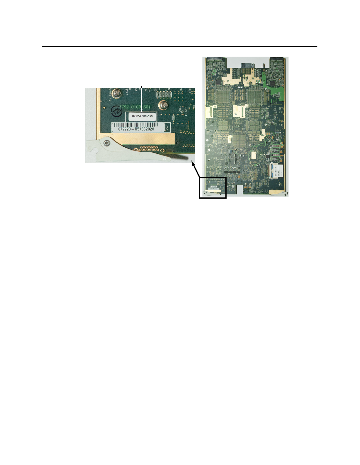
To find your assembly number, look at the underside of the board near the bottom ejector
(see picture below). The assembly number is printed on a small white label.
Replacing the KXO-HDM on a First-Generation KXO-Dual on page 5.
1
Page 6
KXO-HDM Installation
Assembly number
Installing the KXO-HDM on a First-Generation KXO-Dual
Installing the KXO-HDM on a First-Generation KXO-Dual
This installation procedure applies to the first generation of KXO-Dual boards only, which
have an assembly number between 0792-0100-400 and 0792-0100-599. See
on page 1, for information on locating the assembly number.
The installation kit includes the following:
A - One KXO-HDM mezzanine
B - Seven screws M2.5 × 6mm
C - Seven lock washers
D - Two screws 4-40 × ¼ with lock washer
E - Four washers
F - Four screw-mount cable retainers
G - Two adhesive cable retainers
Since installing the KXO-HDM on a KXO-Dual does not involve connecting the mezzanine’s
coaxial cables (which are only meant to implement 1080p support on the KXO-Dual3),
items D, E, F and G are not used, and only five M2.5 × 6mm screws and five lock washers are
needed.
Introduction
2
Page 7

KXO-HDM
Not needed for installation
on a legacy KXO-Dual card
KX-JTAG PULLUP
Battery
Installation Instructions
Before you start, make sure that you have a Phillips #1 screwdriver at hand, and that you are
wearing a static control wrist strap. Allow approximately 15
minutes to complete the
installation.
To install the KXO-HDM on a KXO-Dual card
1 Lay your KXO-Dual card on a work surface.
2 Remove the small PCB (KX-JTAG PULLUP, part no. 1770-5500-100), next to the battery, in
the area near the bottom ejector, by gently pulling it away from the card.
The mezzanine is installed in the lower left corner of the card.
3 Locate the two mezzanine connectors as shown below.
3
Page 8

KXO-HDM Installation
Mezzanine connectors
Connector areas
Five mezzanine
mounting holes
Place mezzanine under
heatsink mounting bracket
Installing the KXO-HDM on a First-Generation KXO-Dual
4 Place the mezzanine carefully unto the KXO-Dual card connectors.
The mezzanine fits underneath the large heatsink mounting bracket shown below.
5 While supporting the underside of the main board, apply pressure in the connector
areas until the mezzanine is fully connected.
4
Page 9

Installation Instructions
KX-JTAG PULLUP
Battery
6 Place the five screws B and the five lock washers C in the mounting holes (shown
above), and tighten carefully to attach the mezzanine to the spacers on the card.
7 Reinstall the small PCB that you had to remove in step 2 (see page 3).
The mezzanine installation is now complete. Reseat the KXO-Dual card in the frame.
Replacing the KXO-HDM on a First-Generation KXO-Dual
This replacement procedure applies to the first generation of KXO-Dual boards only, which
have an assembly number between 0792-0100-400 and 0792-0100-599. See
on page 1, for information on locating the assembly number.
Before you start, make sure that you have a Phillips #1 screwdriver at hand, and that you are
wearing a static control wrist strap. Allow approximately 15
installation.
To replace the KXO-HDM on a KXO-Dual card
1 Lay your KXO-Dual card on a work surface.
2 Remove the small PCB (KX-JTAG PULLUP, part no. 1770-5500-100), next to the battery, in
the area near the bottom ejector, by gently pulling it away from the card.
minutes to complete the
KXO-HDM
Introduction
3 Remove the five screws and washers.
5
Page 10

KXO-HDM Installation
Replacing the KXO-HDM on a First-Generation KXO-Dual
4 Carefully lift the KXO-HDM mezzanine to separate the connectors.
5 Place the new KXO-HDM mezzanine carefully unto the KXO-Dual card connectors.
The mezzanine fits underneath the large heatsink mounting bracket shown below.
6 While supporting the underside of the main board, apply pressure in the connector
areas until the mezzanine is fully connected.
6
Page 11

KXO-HDM
Connector areas
Five mezzanine
mounting holes
Place mezzanine under
heatsink mounting bracket
Installation Instructions
7 Place the five screws and five lock washers you removed in step 3 back in their
mounting holes (shown above), and tighten lightly.
8 Reinstall the small PCB that you had to remove in step 2 (see page 5).
The mezzanine replacement is now complete. Reseat the KXO-Dual card in the frame.
Installing the KXO-HDM on a KXO-Dual3
This installation procedure applies to the KXO-Dual3 boards only, which have assembly
numbers 0792-0100-600 and above. See
locating the assembly number.
The contents of the installation kit are shown in the picture below:
A - One KXO-HDM mezzanine
B - Seven screws M2.5 × 6mm
C - Seven lock washers
D - Two screws 4-40 × ¼ with lock washer
E - Four washers
F - Four screw-mount cable retainers
G - Two adhesive cable retainers
Introduction on page 1, for information on
7
Page 12

KXO-HDM Installation
KX-JTAG PULLUP
Battery
Installing the KXO-HDM on a KXO-Dual3
Before you start, make sure that you have the Phillips #1 screwdriver, and long nose flat
pliers needed to perform this installation, and that you are wearing a static control wrist
strap. Allow approximately 20
minutes to complete the installation.
To install the KXO-HDM on a KXO-Dual3 card
1 Lay your KXO-Dual3 card on a work surface.
2 Remove the small PCB (KX-JTAG PULLUP, part no. 1770-5500-100), next to the battery, in
the area near the bottom ejector, by gently pulling it away from the card.
The mezzanine is installed in the lower left corner of the card.
3 Locate the two mezzanine connectors as shown below.
8
Page 13

KXO-HDM
Mezzanine connectors
Connector areas
Five mezzanine
mounting holes
Place mezzanine under
heatsink mounting bracket
Installation Instructions
4 Place the mezzanine carefully unto the KXO-Dual3 card connectors.
The mezzanine fits underneath the large heatsink mounting bracket shown below.
5 While supporting the underside of the main board, apply pressure in the connector
areas until the mezzanine is fully connected.
9
Page 14

KXO-HDM Installation
Connector J6 Connector J7
Installing the KXO-HDM on a KXO-Dual3
6 Place five screws B and five lock washers C in the mounting holes (shown above), and
tighten carefully to attach the mezzanine to the spacers on the card.
7 Unplug the coaxial cables from the dummy connectors, open the plastic cable ties, and
then unwind the cables.
TIP
To open the cable ties without cutting them, crush their ratchet box by using
long nose flat pliers.
The picture below shows where the working connectors J6 and J7 are located.
10
8 Turn the card over, and then use the cut-out on the front edge to route the cables.
9 Plug the coaxial cables in the two miniature connectors as follows:
• mezzanine connector J6 to KXO-Dual3 card connector J3000,
• mezzanine connector J7 to KXO-Dual3 card connector J3001.
Page 15

KXO-HDM
Connector J3001
Screws B
Lock washers C
Washers E
Cable retainers F
Screws D
Washers E
Cable retainers F
Cable retainers G Connector J3000
Installation Instructions
10 Secure the coaxial cables using the hardware described in the picture above.
The four washers E are inserted between lock washer and cable retainer. In most of the
mounting holes used, there are hexagonal supports that need to be removed before
attaching the plastic cable retainers.
11 Reinstall the small PCB that you had to remove in step 2 (see page 8).
The mezzanine installation is now complete. Reseat the KXO-Dual3 card in the frame.
Replacing the KXO-HDM on a KXO-Dual3
This replacement procedure applies to the KXO-Dual3 boards only, which have assembly
numbers 0792-0100-600 and above. See
locating the assembly number.
Before you start, make sure that you have a Phillips #1 screwdriver at hand, and that you are
wearing a static control wrist strap. Allow approximately 15
installation.
To replace the KXO-HDM on a KXO-Dual3 card
1 Lay your KXO-Dual3 card on a work surface.
2 Remove the small PCB (KX-JTAG PULLUP, part no. 1770-5500-100), next to the battery, in
the area near the bottom ejector, by gently pulling it away from the card.
Introduction on page 1, for information on
minutes to complete the
11
Page 16

KXO-HDM Installation
KX-JTAG PULLUP
Battery
Connector J6 Connector J7
Replacing the KXO-HDM on a KXO-Dual3
3 Remove the five screws and washers, and unplug both coaxial cables from the J6 and
J7 connectors.
IMPORTANT
Note where the connectors J6 and J7 are located.
4 Carefully lift the KXO-HDM mezzanine to separate the connectors.
5 Place the new KXO-HDM mezzanine carefully unto the KXO-Dual3 card connectors.
The mezzanine fits underneath the large heatsink mounting bracket shown below.
12
Page 17

KXO-HDM
Connector areas
Four mezzanine
mounting holes
Place mezzanine under
heatsink mounting bracket
Installation Instructions
6 While supporting the underside of the main board, apply pressure in the connector
areas until the mezzanine is fully connected.
7 Place the five screws and five lock washers you removed in step 3 back in their
mounting holes (shown above), and tighten lightly.
Assuming the original coaxial cables you disconnected in step 3 are still in good condition, you can unplug the new mezzanine’s coaxial cables from their connectors, and
save them for future use.
8 Plug the coaxial cables you disconnected in step 3 back into the J6 and J7 connectors,
making sure that:
• the cable you connect to mezzanine connector J6 is the one attached to the KXODual3 card connector J3000, and
• the cable you connect to mezzanine connector J7 is the one attached to the KXODual3 card connector J3001.
9 Reinstall the small PCB that you had to remove in step 2 (see page 11).
The mezzanine replacement is now complete. Reseat the KXO-Dual3 card in the frame.
13
Page 18

Page 19

Contact Us
Miranda Technical Support
For technical assistance, please contact the Miranda Technical Support center nearest you:
Americas
Office hours: 9:00 a.m. – 9:00 p.m. (EST)
Telephone: 1-800-224-7882
Fax: +1 514 335 1614
E-mail: support@miranda.com
Europe, Middle East, Africa, UK
Office hours: 9:00 a.m. – 6:00 p.m. (GMT)
Telephone: +44 118 952 3444
Fax: +44 118 952 3401
E-mail: eurotech@miranda.com
France
Office hours: 9:00 a.m. – 5:00 p.m. (GMT+1)
Telephone: +33 1 55 86 87 88
Fax: +33 1 55 86 00 29
E-mail: eurotech@miranda.com
Asia
Office hours: 9:00 a.m. – 5:00 p.m. (GMT+8)
Telephone: +852 2539 6987
Fax: +852 2539 0804
E-mail: asiatech@miranda.com
China
Telephone: +86 10 5873 1814
E-mail: asiatech@miranda.com
EMERGENCY After Hours (Global)
Toll Free: 1-800-224-7882 (US and Canada)
Telephone: +1 514 333 1772
Corporate Head Office
Miranda Technologies
3499 Douglas-B.-Floreani, St-Laurent, Quebec, Canada H4S 2C6
Telephone: +1 514 333 1772
Fax: +1 514 333 9828
Web: www.miranda.com
 Loading...