

Page 1
Installation Manual
Issue 5 Rev 1
2020-10-29
KULA
PRODUCTION SWITCHER
All manuals and user guides at all-guides.com
Page 2

ii
Notices
Related Products
This Installation Manual Covers:
• Kula IP Mainframe and Control Panels and Ancillary Panels
• Kula SDI Mainframe and Control Panels and Ancillary Panels
• Kula 12G-SDI Mainframe and Control Panels and Ancillary Panels
FCC Compliance
In order to comply with FCC/CFR47: Part 15 regulations, it is necessary to use high-quality,
triple-screened Media or Monitor cable assemblies with integrated ferrite suppression at
both ends.
Patent Information
This product may be protected by one or more patents.
For further information, please visit: www.grassvalley.com/patents/
Copyright and Trademark Notice
Grass Valley®, GV® and the Grass Valley logo and/or any of the Grass Valley products listed
in this document are trademarks or registered trademarks of GVBB Holdings SARL, Grass
Valley USA, LLC, or one of its affiliates or subsidiaries. All other intellectual property rights
are owned by GVBB Holdings SARL, Grass Valley USA, LLC, or one of its affiliates or
subsidiaries. All third party intellectual property rights (including logos or icons) remain the
property of their respective owners.
Copyright © 2017 - 2020 GVBB Holdings SARL and Grass Valley USA, LLC. All rights reserved.
Specifications are subject to change without notice.
All manuals and user guides at all-guides.com
Page 3
iii
Kula
Installation Manual
Terms and Conditions
Please read the following terms and conditions carefully. By using Kula documentation, you
agree to the following terms and conditions.
Grass Valley hereby grants permission and license to owners of Kula to use their product
manuals for their own internal business use. Manuals for Grass Valley products may not be
reproduced or transmitted in any form or by any means, electronic or mechanical, including
photocopying and recording, for any purpose unless specifically authorized in writing by
Grass Valley.
A Grass Valley manual may have been revised to reflect changes made to the product
during its manufacturing life. Thus, different versions of a manual may exist for any given
product. Care should be taken to ensure that one obtains the proper manual version for a
specific product serial number.
Information in this document is subject to change without notice and does not represent a
commitment on the part of Grass Valley.
Warranty information is available from the Legal Terms and Conditions section of Grass
Valley’s website (
www.grassvalley.com).
Important Safety Information
This section provides important safety guidelines for operators and service personnel.
Specific warnings and cautions appear throughout the manual where they apply. Please
read and follow this important information, especially those instructions related to the risk
of electric shock or injury to persons.
Symbols and Their Meanings
Title Kula Installation Manual
Part Number Issue 5 Rev 1
Revision 2020-10-29, 13:25
Indicates that dangerous high voltage is present within the equipment
enclosure that may be of sufficient magnitude to constitute a risk of electric
shock.
Indicates that the user, operator or service technician should refer to the product
manuals for important operating, maintenance, or service instructions.
This is a prompt to note the fuse rating when replacing fuses. The fuse
referenced in the text must be replaced with one having the ratings indicated.
All manuals and user guides at all-guides.com
Page 4
iv
Notices
Warnings
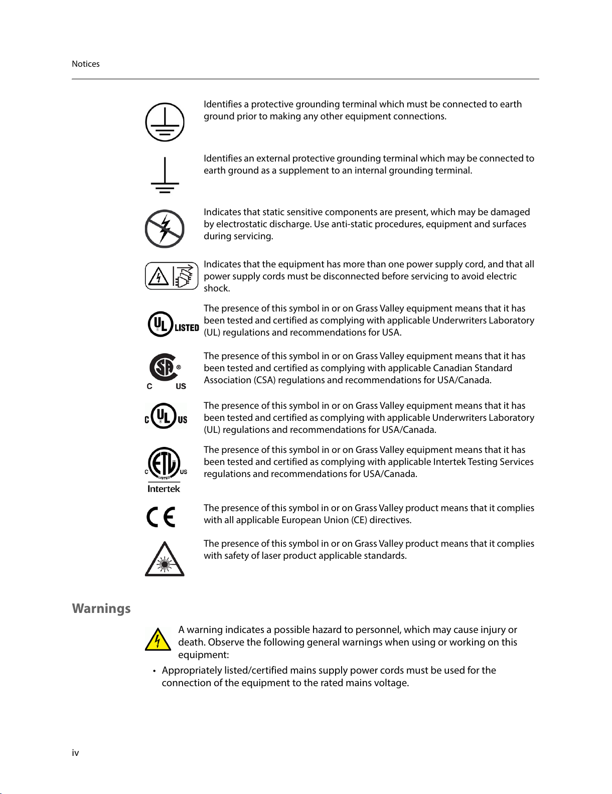
A warning indicates a possible hazard to personnel, which may cause injury or
death. Observe the following general warnings when using or working on this
equipment:
• Appropriately listed/certified mains supply power cords must be used for the
connection of the equipment to the rated mains voltage.
Identifies a protective grounding terminal which must be connected to earth
ground prior to making any other equipment connections.
Identifies an external protective grounding terminal which may be connected to
earth ground as a supplement to an internal grounding terminal.
Indicates that static sensitive components are present, which may be damaged
by electrostatic discharge. Use anti-static procedures, equipment and surfaces
during servicing.
Indicates that the equipment has more than one power supply cord, and that all
power supply cords must be disconnected before servicing to avoid electric
shock.
The presence of this symbol in or on Grass Valley equipment means that it has
been tested and certified as complying with applicable Underwriters Laboratory
(UL) regulations and recommendations for USA.
The presence of this symbol in or on Grass Valley equipment means that it has
been tested and certified as complying with applicable Canadian Standard
Association (CSA) regulations and recommendations for USA/Canada.
The presence of this symbol in or on Grass Valley equipment means that it has
been tested and certified as complying with applicable Underwriters Laboratory
(UL) regulations and recommendations for USA/Canada.
The presence of this symbol in or on Grass Valley equipment means that it has
been tested and certified as complying with applicable Intertek Testing Services
regulations and recommendations for USA/Canada.
The presence of this symbol in or on Grass Valley product means that it complies
with all applicable European Union (CE) directives.
The presence of this symbol in or on Grass Valley product means that it complies
with safety of laser product applicable standards.
All manuals and user guides at all-guides.com
Page 5
v
Kula
Installation Manual
• This product relies on the building's installation for short-circuit (over-current)
protection. Ensure that a fuse or circuit breaker for the rated mains voltage is used on
the phase conductors.
• Any instructions in this manual that require opening the equipment cover or enclosure
are for use by qualified service personnel only.
• Do not operate the equipment in wet or damp conditions.
• This equipment is grounded through the grounding conductor of the power cords. To
avoid electrical shock, plug the power cords into a properly wired receptacle before
connecting the equipment inputs or outputs.
• Route power cords and other cables so they are not likely to be damaged. Properly
support heavy cable bundles to avoid connector damage.
• Disconnect power before cleaning the equipment. Do not use liquid or aerosol
cleaners; use only a damp cloth.
• Dangerous voltages may exist at several points in this equipment. To avoid injury, do
not touch exposed connections and components while power is on.
• High leakage current may be present. Earth connection of product is essential before
connecting power.
• Prior to servicing, remove jewelry such as rings, watches, and other metallic objects.
• To avoid fire hazard, use only the fuse type and rating specified in the service
instructions for this product, or on the equipment.
• To avoid explosion, do not operate this equipment in an explosive atmosphere.
• Use proper lift points. Do not use door latches to lift or move equipment.
• Avoid mechanical hazards. Allow all rotating devices to come to a stop before servicing.
• Have qualified service personnel perform safety checks after any service.
Cautions
A caution indicates a possible hazard to equipment that could result in equipment
damage. Observe the following cautions when operating or working on this
equipment:
• This equipment is meant to be installed in a restricted access location.
• When installing this equipment, do not attach the power cord to building surfaces.
• Products that have no on/off switch, and use an external power supply must be
installed in proximity to a main power outlet that is easily accessible.
• Use the correct voltage setting. If this product lacks auto-ranging power supplies,
before applying power ensure that each power supply is set to match the power
source.
• Provide proper ventilation. To prevent product overheating, provide equipment
ventilation in accordance with the installation instructions.
• Do not operate with suspected equipment failure. If you suspect product damage or
equipment failure, have the equipment inspected by qualified service personnel.
• To reduce the risk of electric shock, do not perform any servicing other than that
contained in the operating instructions unless you are qualified to do so. Refer all
servicing to qualified service personnel.
All manuals and user guides at all-guides.com
Page 6
vi
Notices
• This unit may have more than one power supply cord. Disconnect all power supply
cords before servicing to avoid electric shock.
• Follow static precautions at all times when handling this equipment. Servicing should
be done in a static-free environment.
• To reduce the risk of electric shock, plug each power supply cord into separate branch
circuits employing separate service grounds.
Electrostatic Discharge (ESD) Protection
Electrostatic discharge occurs when electronic components are improperly
handled and can result in intermittent failure or complete damage adversely
affecting an electrical circuit. When you remove and replace any card from a frame
always follow ESD-prevention procedures:
• Ensure that the frame is electrically connected to earth ground through the power cord
or any other means if available.
• Wear an ESD wrist strap ensuring that it makes good skin contact. Connect the
grounding clip to an unpainted surface of the chassis frame to safely ground unwanted
ESD voltages. If no wrist strap is available, ground yourself by touching the unpainted
metal part of the chassis.
• For safety, periodically check the resistance value of the antistatic strap, which should
be between
1 and 10 megohms.
• When temporarily storing a card make sure it is placed in an ESD bag.
• Cards in an earth grounded metal frame or casing do not require any special ESD
protection.
Battery Handling
This product may include a backup battery. There is a danger of explosion if the
battery is replaced incorrectly. Replace the battery only with the same or equivalent
type recommended by the manufacturer. Dispose of used batteries according to
the manufacturer’s instructions. Before disposing of your Grass Valley equipment, please
review the Disposal and Recycling Information at:
http://www.grassvalley.com/assets/media/5692/Take-Back_Instructions.pdf
Cautions for LCD and TFT Displays
Excessive usage may harm your vision. Rest for 10 minutes for every 30 minutes of
usage.
If the LCD or TFT glass is broken, handle glass fragments with care when disposing
of them. If any fluid leaks out of a damaged glass cell, be careful not to get the liquid crystal
fluid in your mouth or skin. If the liquid crystal touches your skin or clothes, wash it off
immediately using soap and water. Never swallow the fluid. The toxicity is extremely low
but caution should be exercised at all times.
All manuals and user guides at all-guides.com
Page 7
vii
Kula
Installation Manual
Mesures de sécurité et avis importants
La présente section fournit des consignes de sécurité importantes pour les opérateurs et le
personnel de service. Des avertissements ou mises en garde spécifiques figurent dans le
manuel, dans les sections où ils s’appliquent. Prenez le temps de bien lire les consignes et
assurez-vous de les respecter, en particulier celles qui sont destinées à prévenir les
décharges électriques ou les blessures.
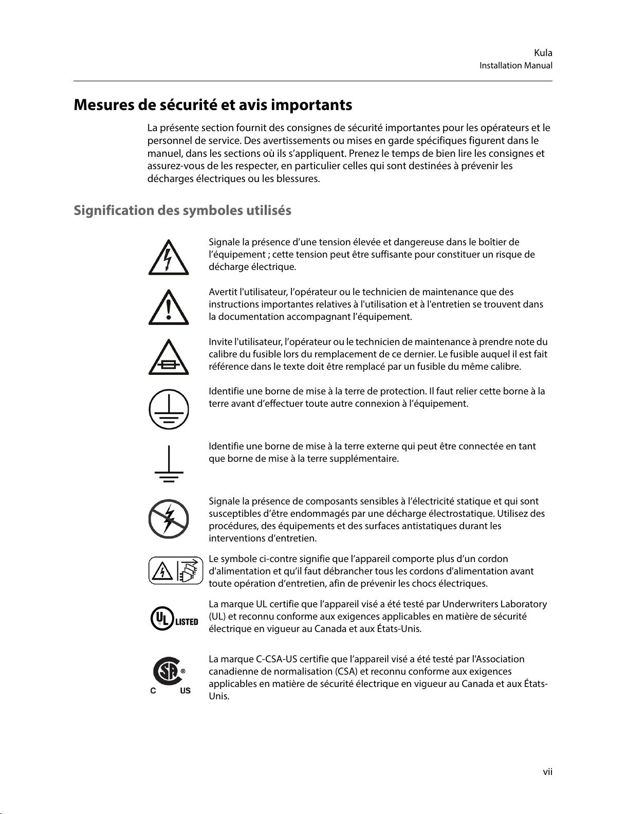
Signification des symboles utilisés
Signale la présence d’une tension élevée et dangereuse dans le boîtier de
l’équipement
; cette tension peut être suffisante pour constituer un risque de
décharge électrique.
Avertit l'utilisateur, l’opérateur ou le technicien de maintenance que des
instructions importantes relatives à l'utilisation et à l'entretien se trouvent dans
la documentation accompagnant l’équipement.
Invite l'utilisateur, l’opérateur ou le technicien de maintenance à prendre note du
calibre du fusible lors du remplacement de ce dernier. Le fusible auquel il est fait
référence dans le texte doit être remplacé par un fusible du même calibre.
Identifie une borne de mise à la terre de protection. Il faut relier cette borne à la
terre avant d’effectuer toute autre connexion à l’équipement.
Identifie une borne de mise à la terre externe qui peut être connectée en tant
que borne de mise à la terre supplémentaire.
Signale la présence de composants sensibles à l’électricité statique et qui sont
susceptibles d’être endommagés par une décharge électrostatique. Utilisez des
procédures, des équipements et des surfaces antistatiques durant les
interventions d’entretien.
Le symbole ci-contre signifie que l’appareil comporte plus d’un cordon
d'alimentation et qu’il faut débrancher tous les cordons d'alimentation avant
toute opération d’entretien, afin de prévenir les chocs électriques.
La marque UL certifie que l’appareil visé a été testé par Underwriters Laboratory
(UL) et reconnu conforme aux exigences applicables en matière de sécurité
électrique en vigueur au Canada et aux États-Unis.
La marque C-CSA-US certifie que l’appareil visé a été testé par l'Association
canadienne de normalisation (CSA) et reconnu conforme aux exigences
applicables en matière de sécurité électrique en vigueur au Canada et aux États-
Unis.
All manuals and user guides at all-guides.com
Page 8
viii
Notices
Avertissements
Les avertissements signalent des conditions ou des pratiques susceptibles
d’occasionner des blessures graves, voire fatales. Veuillez vous familiariser avec les
avertissements d’ordre général ci-dessous
:
• Un cordon d’alimentation dûment homologué doit être utilisé pour connecter
l’appareil à une tension de secteur de 120
V CA ou 240 V CA.
• La protection de ce produit contre les courts-circuits (surintensités) dépend de
l’installation électrique du bâtiment. Assurez-vous qu'un fusible ou un disjoncteur pour
120
V CA ou 240 V CA est utilisé sur les conducteurs de phase.
• Dans le présent manuel, toutes les instructions qui nécessitent d’ouvrir le couvercle de
l’équipement sont destinées exclusivement au personnel technique qualifié.
• N’utilisez pas cet appareil dans un environnement humide.
• Cet équipement est mis à la terre par le conducteur de mise à la terre des cordons
d’alimentation. Pour éviter les chocs électriques, branchez les cordons d’alimentation
sur une prise correctement câblée avant de brancher les entrées et sorties de
l’équipement.
• Acheminez les cordons d’alimentation et autres câbles de façon à ce qu’ils ne risquent
pas d’être endommagés. Supportez correctement les enroulements de câbles afin de
ne pas endommager les connecteurs.
• Coupez l’alimentation avant de nettoyer l’équipement. Ne pas utiliser de nettoyants
liquides ou en aérosol. Utilisez uniquement un chiffon humide.
• Des tensions dangereuses peuvent exister en plusieurs points dans cet équipement.
Pour éviter toute blessure, ne touchez pas aux connexions ou aux composants exposés
lorsque l’appareil est sous tension.
• Avant de procéder à toute opération d’entretien ou de dépannage, enlevez tous vos
bijoux (notamment vos bagues, votre montre et autres objets métalliques).
• Pour éviter tout risque d’incendie, utilisez uniquement les fusibles du type et du calibre
indiqués sur l’équipement ou dans la documentation qui l’accompagne.
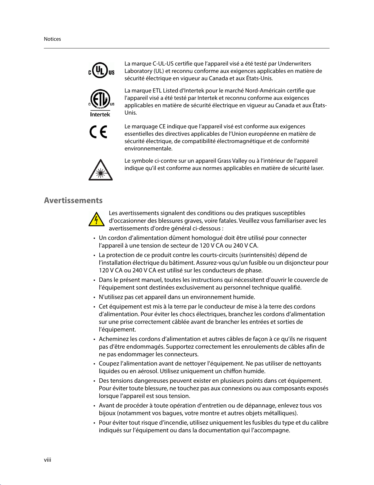
La marque C-UL-US certifie que l’appareil visé a été testé par Underwriters
Laboratory (UL) et reconnu conforme aux exigences applicables en matière de
sécurité électrique en vigueur au Canada et aux États-Unis.
La marque ETL Listed d’Intertek pour le marché Nord-Américain certifie que
l’appareil visé a été testé par Intertek et reconnu conforme aux exigences
applicables en matière de sécurité électrique en vigueur au Canada et aux États-
Unis.
Le marquage CE indique que l’appareil visé est conforme aux exigences
essentielles des directives applicables de l’Union européenne en matière de
sécurité électrique, de compatibilité électromagnétique et de conformité
environnementale.
Le symbole ci-contre sur un appareil Grass Valley ou à l’intérieur de l’appareil
indique qu’il est conforme aux normes applicables en matière de sécurité laser.
All manuals and user guides at all-guides.com
Page 9
ix
Kula
Installation Manual
• Ne pas utiliser cet appareil dans une atmosphère explosive.
• Présence possible de courants de fuite. Un raccordement à la masse est indispensable
avant la mise sous tension.
• Après tout travail d’entretien ou de réparation, faites effectuer des contrôles de sécurité
par le personnel technique qualifié.
Mises en garde
Les mises en garde signalent des conditions ou des pratiques susceptibles
d’endommager l’équipement. Veuillez vous familiariser avec les mises en garde ci-
dessous
:
• L’appareil est conçu pour être installé dans un endroit à accès restreint.
• Au moment d’installer l’équipement, ne fixez pas les cordons d’alimentation aux
surfaces intérieures de l’édifice.
• Les produits qui n'ont pas d’interrupteur marche-arrêt et qui disposent d’une source
d’alimentation externe doivent être installés à proximité d'une prise de courant facile
d’accès.
• Si l’équipement n’est pas pourvu d’un modules d’alimentation auto-adaptables, vérifiez
la configuration de chacun des modules d'alimentation avant de les mettre sous
tension.
• Assurez une ventilation adéquate. Pour éviter toute surchauffe du produit, assurez une
ventilation de l’équipement conformément aux instructions d’installation.
• N’utilisez pas l’équipement si vous suspectez un dysfonctionnement du produit. Faites-
le inspecter par un technicien qualifié.
• Pour réduire le risque de choc électrique, n'effectuez pas de réparations autres que
celles qui sont décrites dans le présent manuel, sauf si vous êtes qualifié pour le faire.
Confiez les réparations à un technicien qualifié. La maintenance doit se réaliser dans un
milieu libre d’électricité statique.
• L’appareil peut comporter plus d’un cordon d'alimentation. Afin de prévenir les chocs
électriques, débrancher tous les cordons d'alimentation avant toute opération
d’entretien.
• Veillez à toujours prendre les mesures de protection antistatique appropriées quand
vous manipulez l’équipement.
• Pour réduire le risque de choc électrique, branchez chaque cordon d'alimentation dans
des circuits de dérivation distincts utilisant des zones de service distinctes.
Protection contre les décharges électrostatiques (DES)
Une décharge électrostatique peut se produire lorsque des composants
électroniques ne sont pas manipulés de manière adéquate, ce qui peut entraîner
des défaillances intermittentes ou endommager irrémédiablement un circuit
électrique. Au moment de remplacer une carte dans un châssis, prenez toujours les
mesures de protection antistatique appropriées
:
• Assurez-vous que le châssis est relié électriquement à la terre par le cordon
d'alimentation ou tout autre moyen disponible.
All manuals and user guides at all-guides.com
Page 10

x
Notices
• Portez un bracelet antistatique et assurez-vous qu'il est bien en contact avec la peau.
Connectez la pince de masse à une surface non peinte du châssis pour détourner à la
terre toute tension électrostatique indésirable. En l’absence de bracelet antistatique,
déchargez l’électricité statique de votre corps en touchant une surface métallique non
peinte du châssis.
• Pour plus de sécurité, vérifiez périodiquement la valeur de résistance du bracelet
antistatique. Elle doit se situer entre 1 et 10
mégohms.
• Si vous devez mettre une carte de côté, assurez-vous de la ranger dans un sac
protecteur antistatique.
• Les cartes qui sont reliées à un châssis ou boîtier métallique mis à la terre ne
nécessitent pas de protection antistatique spéciale.
Manipulation de la pile
Ce produit peut inclure une pile de sauvegarde. Il y a un risque d'explosion si la pile
est remplacée de manière incorrecte. Remplacez la pile uniquement par un modèle
identique ou équivalent recommandé par le fabricant. Disposez des piles usagées
conformément aux instructions du fabricant. Avant de vous séparer de votre équipement
Grass Valley, veuillez consulter les informations de mise au rebut et de recyclage à:
http://www.grassvalley.com/assets/media/5692/Take-Back_Instructions.pdf
Précautions pour les écrans LCD et TFT
Regarder l’écran pendant une trop longue période de temps peut nuire à votre
vision. Prenez une pause de 10 minutes, après 30 minutes d’utilisation.
Si l'écran LCD ou TFT est brisé, manipulez les fragments de verre avec précaution au
moment de vous en débarrasser. veillez à ce que le cristal liquide n'entre pas en contact
avec la peau ou la bouche. En cas de contact avec la peau ou les vêtements, laver
immédiatement à l'eau savonneuse. Ne jamais ingérer le liquide. La toxicité est
extrêmement faible, mais la prudence demeure de mise en tout temps.
Environmental Information
European (CE) WEEE directive.
This symbol on the product(s) means that at the end of life disposal it should not be mixed
with general waste.
All manuals and user guides at all-guides.com
Page 11
xi
Kula
Installation Manual
Visit www.grassvalley.com for recycling information.
Grass Valley believes this environmental information to be correct but cannot guarantee its
completeness or accuracy since it is based on data received from sources outside our
company. All specifications are subject to change without notice.
If you have questions about Grass Valley environmental and social involvement (WEEE,
RoHS, REACH, etc.), please contact us at environment@grassvalley.com .
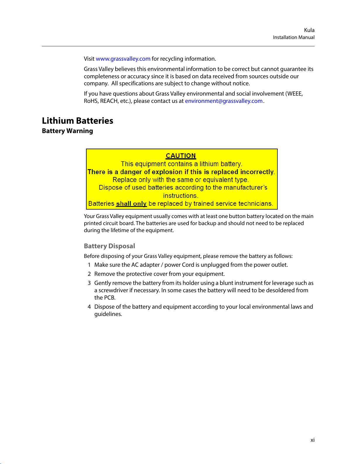
Lithium Batteries
Battery Warning
Your Grass Valley equipment usually comes with at least one button battery located on the main
printed circuit board. The batteries are used for backup and should not need to be replaced
during the lifetime of the equipment.
Battery Disposal
Before disposing of your Grass Valley equipment, please remove the battery as follows:
1 Make sure the AC adapter / power Cord is unplugged from the power outlet.
2 Remove the protective cover from your equipment.
3 Gently remove the battery from its holder using a blunt instrument for leverage such as
a screwdriver if necessary. In some cases the battery will need to be desoldered from
the PCB.
4 Dispose of the battery and equipment according to your local environmental laws and
guidelines.
All manuals and user guides at all-guides.com
Page 12
xii
Notices
WAR NIN G
• Be careful not to short-circuit the battery by adhering to the
appropriate safe handling practices.
• Do not dispose of batteries in a fire as they may explode.
• Batteries may explode if damaged or overheated.
• Do not dismantle, open or shred batteries.
• In the event of a battery leak, do not allow battery liquid to come in
contact with skin or eyes.
• Seek medical help immediately in case of ingestion, inhalation, skin
or eye contact, or suspected exposure to the contents of an opened
battery.
All manuals and user guides at all-guides.com
Page 13
xiii
Kula
Installation Manual
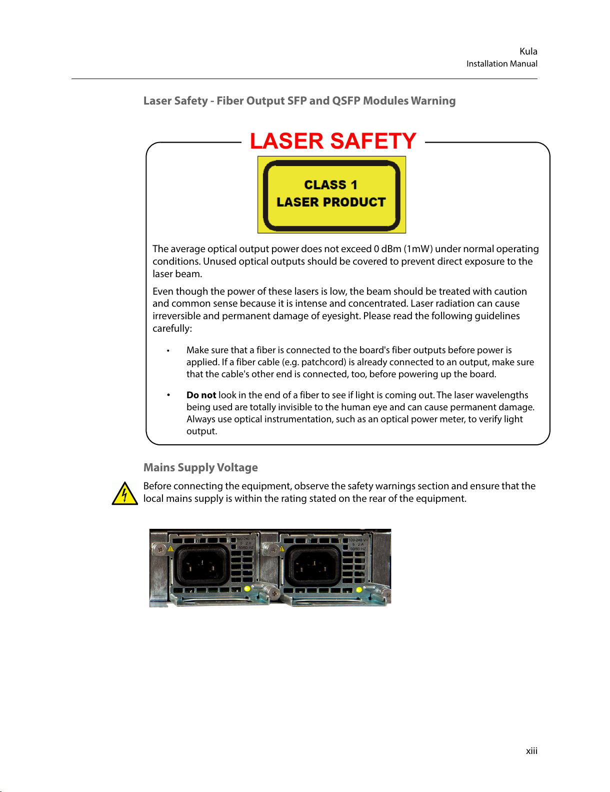
Laser Safety - Fiber Output SFP and QSFP Modules Warning
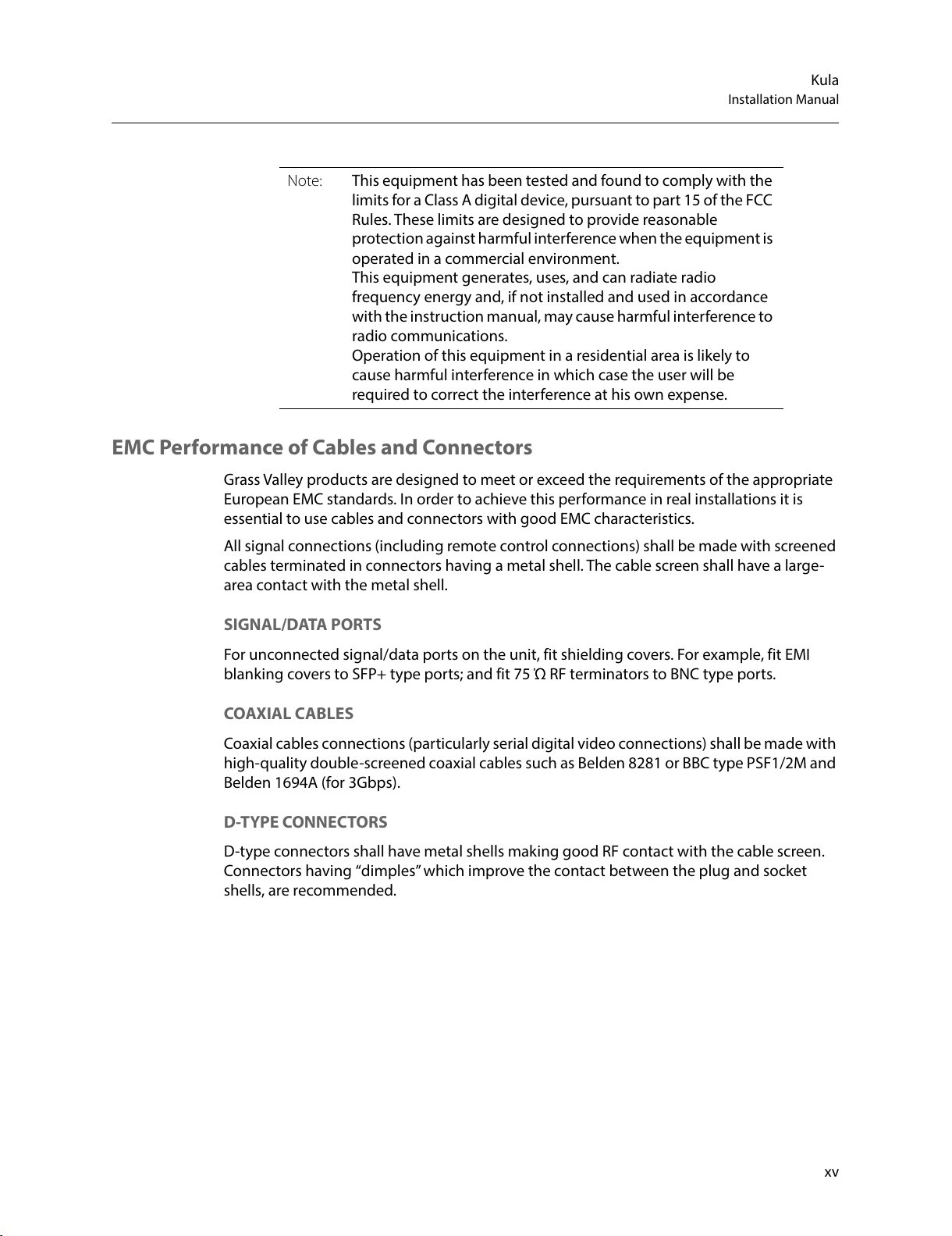
Mains Supply Voltage
Before connecting the equipment, observe the safety warnings section and ensure that the
local mains supply is within the rating stated on the rear of the equipment.
LASER SAFETY
The average optical output power does not exceed 0 dBm (1mW) under normal operating
conditions. Unused optical outputs should be covered to prevent direct exposure to the
laser beam.
Even though the power of these lasers is low, the beam should be treated with caution
and common sense because it is intense and concentrated. Laser radiation can cause
irreversible and permanent damage of eyesight. Please read the following guidelines
carefully:
• Make sure that a fiber is connected to the board's fiber outputs before power is
applied. If a fiber cable (e.g. patchcord) is already connected to an output, make sure
that the cable's other end is connected, too, before powering up the board.
• Do not look in the end of a fiber to see if light is coming out. The laser wavelengths
being used are totally invisible to the human eye and can cause permanent damage.
Always use optical instrumentation, such as an optical power meter, to verify light
output.
All manuals and user guides at all-guides.com
Page 14

xiv
Notices
Safety and EMC Standards
This equipment complies with the following standards:
Safety Standards
Information Technology Equipment - Safety Part 1
EN60950-1: 2006
Safety of Information Technology Equipment Including Electrical Business Equipment.
UL1419 (4th Edition)
Standard for Safety – Professional Video and Audio equipment (UL file number E193966)
EMC Standards
This unit conforms to the following standards:
EN55032:2015 (Class A)
Electromagnetic Compatibility of multimedia equipment - Emission requirements
EN61000-3-2:2014 (Class A)
Electromagnetic Compatibility - Limits for harmonic current emissions
EN61000-3-3:2013
Electromagnetic Compatibility - Limits of voltage changes, voltage fluctuations and flicker
EN55103-2:2009 (Environment E2)
Electromagnetic Compatibility, Product family standard for audio, video, audio-visual and
entertainment lighting control apparatus for professional use. Part 2. Immunity
FCC / CFR 47:Part 15 (Class A)
Federal Communications Commission Rules Part 15, Subpart B
Caution to the user that changes or modifications not expressly approved by the party
responsible for compliance could void the user's authority to operate the equipment.
WAR NIN G
This equipment is compliant with Class A of CISPR 32. In a residential
environment this equipment may cause radio interference.
All manuals and user guides at all-guides.com
Page 15
xv
Kula
Installation Manual
EMC Performance of Cables and Connectors
Grass Valley products are designed to meet or exceed the requirements of the appropriate
European EMC standards. In order to achieve this performance in real installations it is
essential to use cables and connectors with good EMC characteristics.
All signal connections (including remote control connections) shall be made with screened
cables terminated in connectors having a metal shell. The cable screen shall have a large-
area contact with the metal shell.
SIGNAL/DATA PORTS
For unconnected signal/data ports on the unit, fit shielding covers. For example, fit EMI
blanking covers to SFP+ type ports; and fit 75 Ώ RF terminators to BNC type ports.
COAXIAL CABLES
Coaxial cables connections (particularly serial digital video connections) shall be made with
high-quality double-screened coaxial cables such as Belden 8281 or BBC type PSF1/2M and
Belden 1694A (for 3Gbps).
D-TYPE CONNECTORS
D-type connectors shall have metal shells making good RF contact with the cable screen.
Connectors having “dimples” which improve the contact between the plug and socket
shells, are recommended.
Note: This equipment has been tested and found to comply with the
limits for a Class A digital device, pursuant to part 15 of the FCC
Rules. These limits are designed to provide reasonable
protection against harmful interference when the equipment is
operated in a commercial environment.
This equipment generates, uses, and can radiate radio
frequency energy and, if not installed and used in accordance
with the instruction manual, may cause harmful interference to
radio communications.
Operation of this equipment in a residential area is likely to
cause harmful interference in which case the user will be
required to correct the interference at his own expense.
All manuals and user guides at all-guides.com
Page 16

xvi
Notices
All manuals and user guides at all-guides.com
Page 17
1
Table of Contents
Related Products . . . . . . . . . . . . . . . . . . . . . . . . . . . . . . . . . . . . . . . . . . . . . . . . . . . . . . . . . . . . . . . . . . ii
FCC Compliance. . . . . . . . . . . . . . . . . . . . . . . . . . . . . . . . . . . . . . . . . . . . . . . . . . . . . . . . . . . . . . . . . . . ii
Patent Information . . . . . . . . . . . . . . . . . . . . . . . . . . . . . . . . . . . . . . . . . . . . . . . . . . . . . . . . . . . . . . . . ii
Copyright and Trademark Notice. . . . . . . . . . . . . . . . . . . . . . . . . . . . . . . . . . . . . . . . . . . . . . . . . . . ii
Battery Disposal . . . . . . . . . . . . . . . . . . . . . . . . . . . . . . . . . . . . . . . . . . . . . . . . . . . . . . . . . . . . . . xi
Laser Safety - Fiber Output SFP and QSFP Modules Warning . . . . . . . . . . . . . . . . . . .xiii
Mains Supply Voltage . . . . . . . . . . . . . . . . . . . . . . . . . . . . . . . . . . . . . . . . . . . . . . . . . . . . . . . .xiii
Safety and EMC Standards . . . . . . . . . . . . . . . . . . . . . . . . . . . . . . . . . . . . . . . . . . . . . . . . . . . . . . . xiv
Safety Standards . . . . . . . . . . . . . . . . . . . . . . . . . . . . . . . . . . . . . . . . . . . . . . . . . . . . . . . . . . . . xiv
EMC Standards . . . . . . . . . . . . . . . . . . . . . . . . . . . . . . . . . . . . . . . . . . . . . . . . . . . . . . . . . . . . . . xiv
EMC Performance of Cables and Connectors . . . . . . . . . . . . . . . . . . . . . . . . . . . . . . . . . .xv
1 Introduction . . . . . . . . . . . . . . . . . . . . . . . . . . . . . . . . . . . . . . . . . . . 1
About this Manual. . . . . . . . . . . . . . . . . . . . . . . . . . . . . . . . . . . . . . . . . . . . . . . . . . . . . . . . . . . . . 1
2 Cabling and Connections. . . . . . . . . . . . . . . . . . . . . . . . . . . . . . . . 3
Kula KPX, KPP, K1X, K1P and K5P Control Surface Connectors . . . . . . . . . . . . . . . . . . . 3
Connecting the Touch Screen Monitor GUI . . . . . . . . . . . . . . . . . . . . . . . . . . . . . . . . . . . . 6
Kula K1X and K1P Connections . . . . . . . . . . . . . . . . . . . . . . . . . . . . . . . . . . . . . . . . . . . . . . . . 7
Connecting a 2M/E Control Surface together . . . . . . . . . . . . . . . . . . . . . . . . . . . . . . . . . . 8
Mainframe Layout and Connections . . . . . . . . . . . . . . . . . . . . . . . . . . . . . . . . . . . . . . . . . . 10
Mainframe Connections . . . . . . . . . . . . . . . . . . . . . . . . . . . . . . . . . . . . . . . . . . . . . . . . . . . . . .12
Inputs . . . . . . . . . . . . . . . . . . . . . . . . . . . . . . . . . . . . . . . . . . . . . . . . . . . . . . . . . . . . . . . . . . . . . . . 12
Outputs . . . . . . . . . . . . . . . . . . . . . . . . . . . . . . . . . . . . . . . . . . . . . . . . . . . . . . . . . . . . . . . . . . . . . 12
Bi-directional Input/Output BNCs. . . . . . . . . . . . . . . . . . . . . . . . . . . . . . . . . . . . . . . . . . . . . 12
Kula 12G-SDI Mainframe Rear Connectors . . . . . . . . . . . . . . . . . . . . . . . . . . . . . . . . . . . . 13
12G-SDI Mainframe Connections . . . . . . . . . . . . . . . . . . . . . . . . . . . . . . . . . . . . . . . . . . . . . 14
Kula IP Mainframe Connectors. . . . . . . . . . . . . . . . . . . . . . . . . . . . . . . . . . . . . . . . . . . . . . . . 15
IP Mainframe Connections . . . . . . . . . . . . . . . . . . . . . . . . . . . . . . . . . . . . . . . . . . . . . . . . . . . 17
All other Connectors (all Kula mainframes). . . . . . . . . . . . . . . . . . . . . . . . . . . . . . . . . . . . 18
RJ45 - RS422 Serial Ports . . . . . . . . . . . . . . . . . . . . . . . . . . . . . . . . . . . . . . . . . . . . . . . . . . . . . 20
All manuals and user guides at all-guides.com
Page 18
2
Table of Contents
3 Environment and Location . . . . . . . . . . . . . . . . . . . . . . . . . . . . . 23
Environmental Considerations . . . . . . . . . . . . . . . . . . . . . . . . . . . . . . . . . . . . . . . . . . . . . . . .23
Control Surfaces. . . . . . . . . . . . . . . . . . . . . . . . . . . . . . . . . . . . . . . . . . . . . . . . . . . . . . . . . . . . . .24
Mounting a Kula Control Surface into a Desk. . . . . . . . . . . . . . . . . . . . . . . . . . . . . . . . . . 24
Mounting the Kula K5P 1M/E Control Surface into a 19” Rack . . . . . . . . . . . . . . . . . . 25
Mainframe Location and Environment . . . . . . . . . . . . . . . . . . . . . . . . . . . . . . . . . . . . . . . .26
Air Flow through the Mainframe. . . . . . . . . . . . . . . . . . . . . . . . . . . . . . . . . . . . . . . . . . . . . . 26
Mounting the Kula Mainframe into a 19” Rack. . . . . . . . . . . . . . . . . . . . . . . . . . . . . . . . . 28
Ancillary Panels . . . . . . . . . . . . . . . . . . . . . . . . . . . . . . . . . . . . . . . . . . . . . . . . . . . . . . . . . . . . . .29
Mav Remote - Desk and 19” Rack Installation. . . . . . . . . . . . . . . . . . . . . . . . . . . . . . . . . . 29
4 Power Supplies. . . . . . . . . . . . . . . . . . . . . . . . . . . . . . . . . . . . . . . . 33
Mainframe Internal Power Supplies . . . . . . . . . . . . . . . . . . . . . . . . . . . . . . . . . . . . . . . . . . .33
Checking the Kula Power Supplies. . . . . . . . . . . . . . . . . . . . . . . . . . . . . . . . . . . . . . . . . . . . 33
Control Surface External Power Supplies . . . . . . . . . . . . . . . . . . . . . . . . . . . . . . . . . . . . . .34
5 Dimensions . . . . . . . . . . . . . . . . . . . . . . . . . . . . . . . . . . . . . . . . . . . 35
Control Surface Dimensions . . . . . . . . . . . . . . . . . . . . . . . . . . . . . . . . . . . . . . . . . . . . . . . . . .35
Kula KPX Control Surface . . . . . . . . . . . . . . . . . . . . . . . . . . . . . . . . . . . . . . . . . . . . . . . . . . . . .35
Kula K1X Control Surface . . . . . . . . . . . . . . . . . . . . . . . . . . . . . . . . . . . . . . . . . . . . . . . . . . . . .36
Desk Cutout Information for KPX and K1X Control Surfaces. . . . . . . . . . . . . . . . . . . . 37
Kula K1P Control Surface . . . . . . . . . . . . . . . . . . . . . . . . . . . . . . . . . . . . . . . . . . . . . . . . . . . . .39
Kula KPP Control Surface . . . . . . . . . . . . . . . . . . . . . . . . . . . . . . . . . . . . . . . . . . . . . . . . . . . . .40
Desk Cutout Information for KPP and K1P Control Surfaces . . . . . . . . . . . . . . . . . . . . 41
Kula K5P 1M/E (19”) Control Surface . . . . . . . . . . . . . . . . . . . . . . . . . . . . . . . . . . . . . . . . . . 42
Mainframe Dimensions . . . . . . . . . . . . . . . . . . . . . . . . . . . . . . . . . . . . . . . . . . . . . . . . . . . . . . .44
Kula Mainframe . . . . . . . . . . . . . . . . . . . . . . . . . . . . . . . . . . . . . . . . . . . . . . . . . . . . . . . . . . . . . . 44
Ancillary Panels . . . . . . . . . . . . . . . . . . . . . . . . . . . . . . . . . . . . . . . . . . . . . . . . . . . . . . . . . . . . . .45
Mav Remote Dimensions. . . . . . . . . . . . . . . . . . . . . . . . . . . . . . . . . . . . . . . . . . . . . . . . . . . . . 45
LCD and LED Aux Panel Dimensions . . . . . . . . . . . . . . . . . . . . . . . . . . . . . . . . . . . . . . . . . . 46
6 Specifications . . . . . . . . . . . . . . . . . . . . . . . . . . . . . . . . . . . . . . . . . 47
Kula Control Surface Specifications . . . . . . . . . . . . . . . . . . . . . . . . . . . . . . . . . . . . . . . . . . .47
Kula Mainframe . . . . . . . . . . . . . . . . . . . . . . . . . . . . . . . . . . . . . . . . . . . . . . . . . . . . . . . . . . . . . .49
Kula Mainframe Connections. . . . . . . . . . . . . . . . . . . . . . . . . . . . . . . . . . . . . . . . . . . . . . . . . 51
Kula 12G-SDI Mainframe Connections . . . . . . . . . . . . . . . . . . . . . . . . . . . . . . . . . . . . . . . . 52
Kula IP Mainframe Connections . . . . . . . . . . . . . . . . . . . . . . . . . . . . . . . . . . . . . . . . . . . . . . 53
Mav Remote Specifications. . . . . . . . . . . . . . . . . . . . . . . . . . . . . . . . . . . . . . . . . . . . . . . . . . . 55
Mainframe PSU Information (covering all Kula mainframes) . . . . . . . . . . . . . . . . . . . 56
Contact Us . . . . . . . . . . . . . . . . . . . . . . . . . . . . . . . . . . . . . . . . . . . . . . . 57
All manuals and user guides at all-guides.com
Page 19
1
Introduction
About this Manual
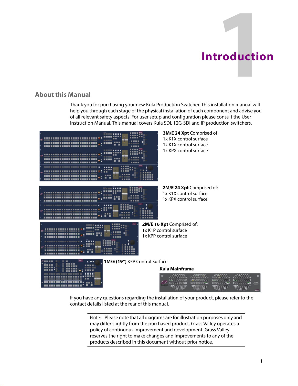
Thank you for purchasing your new Kula Production Switcher. This installation manual will
help you through each stage of the physical installation of each component and advise you
of all relevant safety aspects. For user setup and configuration please consult the User
Instruction Manual. This manual covers Kula SDI, 12G-SDI and IP production switchers.
If you have any questions regarding the installation of your product, please refer to the
contact details listed at the rear of this manual.
3M/E 24 Xpt Comprised of:
1x K1X control surface
1x K1X control surface
1x KPX control surface
2M/E 24 Xpt Comprised of:
1x K1X control surface
1x KPX control surface
2M/E 16 Xpt Comprised of:
1x K1P control surface
1x KPP control surface
1M/E (19”) K5P Control Surface
Kula Mainframe
Note: Please note that all diagrams are for illustration purposes only and
may differ slightly from the purchased product. Grass Valley operates a
policy of continuous improvement and development. Grass Valley
reserves the right to make changes and improvements to any of the
products described in this document without prior notice.
All manuals and user guides at all-guides.com
Page 20

2
Introduction
About this Manual
All manuals and user guides at all-guides.com
Page 21
3
Cabling and Connections
Kula KPX, KPP, K1X, K1P and K5P Control Surface Connectors
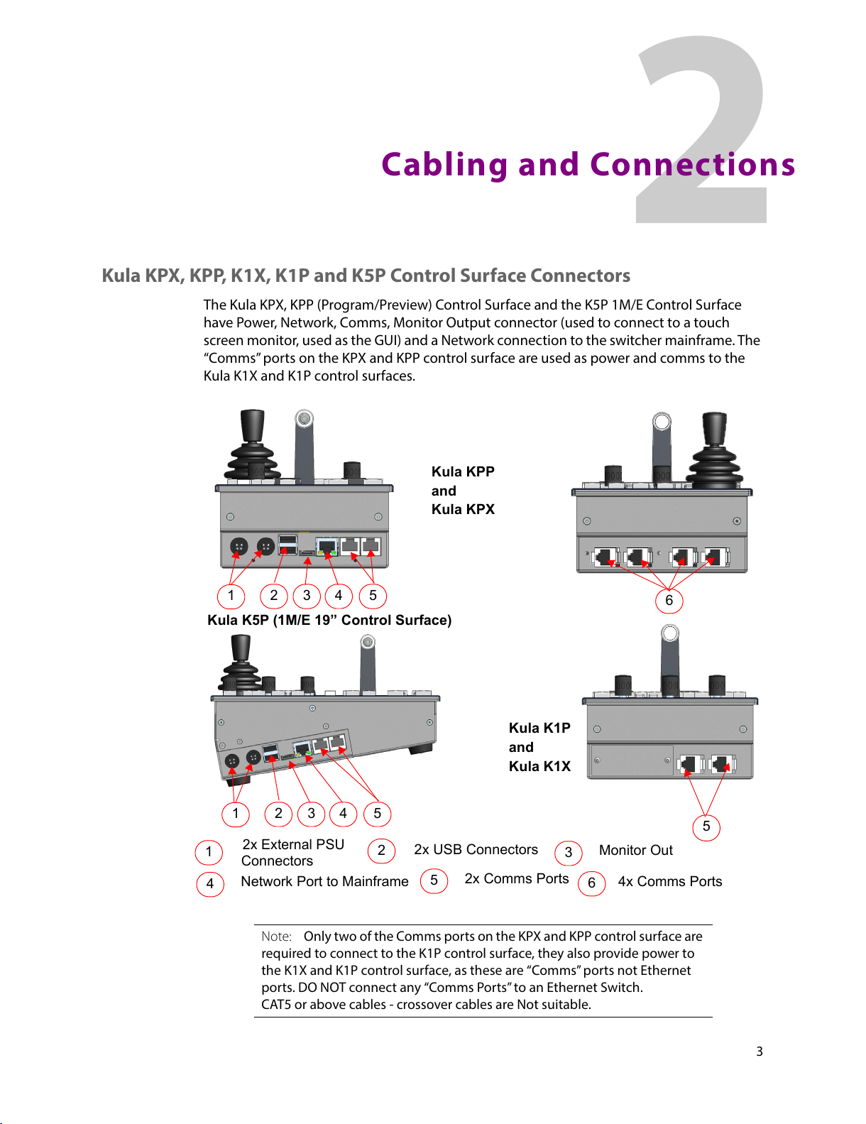
The Kula KPX, KPP (Program/Preview) Control Surface and the K5P 1M/E Control Surface
have Power, Network, Comms, Monitor Output connector (used to connect to a touch
screen monitor, used as the GUI) and a Network connection to the switcher mainframe. The
“Comms” ports on the KPX and KPP control surface are used as power and comms to the
Kula K1X and K1P control surfaces.
2x Comms Ports
Network Port to Mainframe
2x USB Connectors
2x External PSU
Connectors
1
2 3
4
5
Monitor Out
1
2
3
4
5
4x Comms Ports
6
6
1
2 3
4
5
Kula K5P (1M/E 19” Control Surface)
Kula KPP
Kula K1P
5
and
Kula KPX
and
Kula K1X
Note: Only two of the Comms ports on the KPX and KPP control surface are
required to connect to the K1P control surface, they also provide power to
the K1X and K1P control surface, as these are “Comms” ports not Ethernet
ports. DO NOT connect any “Comms Ports” to an Ethernet Switch.
CAT5 or above cables - crossover cables are Not suitable.
All manuals and user guides at all-guides.com
Page 22
4
Cabling and Connections
Kula KPX, KPP, K1X, K1P and K5P Control Surface Connectors
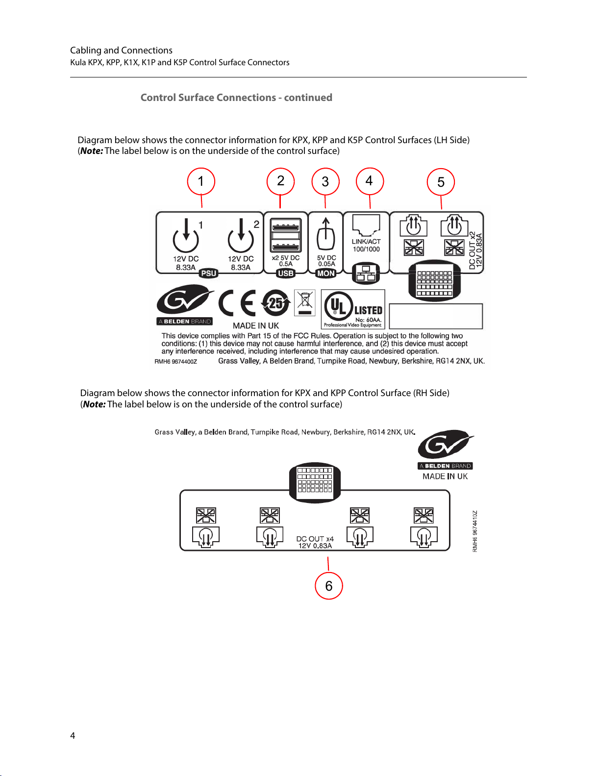
Control Surface Connections - continued
Diagram below shows the connector information for KPX, KPP and K5P Control Surfaces (LH Side)
1
2
3
4
5
(Note: The label below is on the underside of the control surface)
Diagram below shows the connector information for KPX and KPP Control Surface (RH Side)
(Note: The label below is on the underside of the control surface)
6
All manuals and user guides at all-guides.com
Page 23
5
Kula
Installation Manual
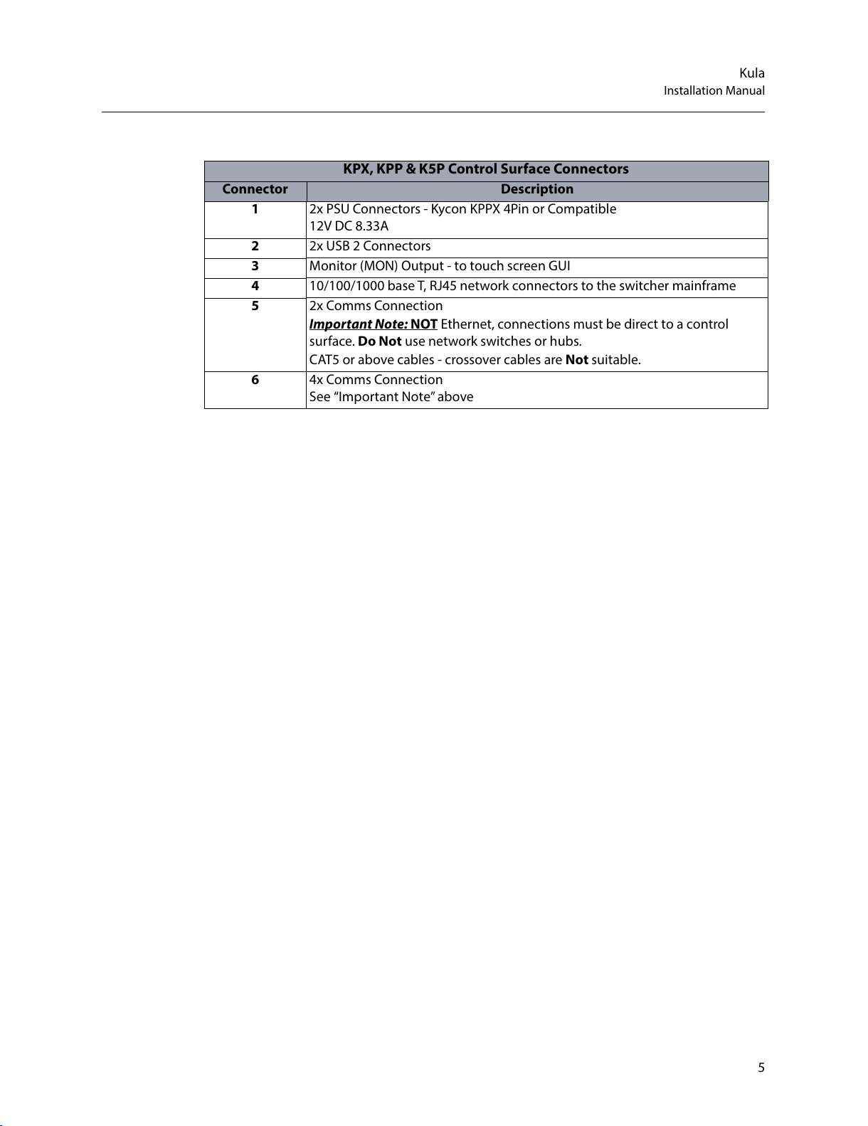
KPX, KPP & K5P Control Surface Connectors
Connector Description
1 2x PSU Connectors - Kycon KPPX 4Pin or Compatible
12V DC 8.33A
2 2x USB 2 Connectors
3 Monitor (MON) Output - to touch screen GUI
4 10/100/1000 base T, RJ45 network connectors to the switcher mainframe
5 2x Comms Connection
Important Note: NOT Ethernet, connections must be direct to a control
surface. Do Not use network switches or hubs.
CAT5 or above cables - crossover cables are Not suitable.
6 4x Comms Connection
See “Important Note” above
All manuals and user guides at all-guides.com
Page 24

6
Cabling and Connections
Kula KPX, KPP, K1X, K1P and K5P Control Surface Connectors
Connecting the Touch Screen Monitor GUI
To connect a touch screen monitor to the Kula KPPP, KPX or K5P output port on the side
near the USB ports, the monitor port is used to connect to an external “computer” touch
screen or normal display monitor. The external monitor must have a 1920 x 1080 display
resolution and it is recommended that the monitor be larger than 21 inches.
Touch sc reen mo nit or - once the external monitor is connected to the Kula control surface,
a USB control lead (shown above) is connected, allowing the touch screen functions to be
used.
Silk Screen from the
side of the Control surface
MON (monitor) output port
KPP or KPX (Note: the K5P control surface is connected in exactly the same way).
MON (monitor) output port
USB port
When using a touch screen
*When using a non-touch screen monitor, connect a USB
Mouse to control the menus.
*When using a touch screen monitor, connect the USB lead
from the monitor to one of the USB ports.
DVI Lead
USB Lead
All manuals and user guides at all-guides.com
Page 25

7
Kula
Installation Manual
Non- touch screen monitor - once the external monitor is connected to the Kula control
surface, a USB mouse (shown above) is used to control the Kula menus on the monitor
screen.
Current Compatible Touch Screen Monitors
iiyama T2250-MTS
iiyama T2236-MSC B1 and B2
iiyama T2252-MTS
GeChic On-Lap 1502
ELO_1002L_1502L
ELO-2002L
Kula K1X and K1P Connections
The Kula K1X and K1P provides a 1 M/E Control Surface that works with the KPP Program
/Preview control surface. All power and comms to the control surface are provided by the
KPP control surface.
Diagram below shows the connector information for K1X and K1P Control Surface (RH Side)
(Note: The label below is on the underside of the control surface)
2x Comms Connection
Important Note:
NOT Ethernet, connections must be direct to the control surface-
Do Not use network switches or hubs.
CAT5 or above cables - crossover cables are Not suitable.
All manuals and user guides at all-guides.com
Page 26

8
Cabling and Connections
Kula KPX, KPP, K1X, K1P and K5P Control Surface Connectors
Connecting a 2M/E Control Surface together
Below is a diagram showing how to connect a KPX and a K1X control surface together.
Connect the KPX control surface to the K1X control surface via the two “Comms” ports on
the right hand side of the control surface.
Kula KPX Control Surface
Kula K1X Control Surface
Kula K1X
Kula KPX
Note: Two “Comms” cables must be connected for correct operation!
All manuals and user guides at all-guides.com
Page 27

9
Kula
Installation Manual
Connecting a 3M/E Control Surface together
Below is a diagram showing how to connect a KPX and a two K1X control surfaces together.
Connect the KPX control surface to the 2x K1X control surfaces via the two “Comms” ports
on the right hand side of the control surface.
Kula KPX Control Surface
2x Kula K1X Control Surface
Kula K1X
Kula K1X
Kula KPX
Note: The two “Comms” cables on each K1X control surface must be
connected to the KPX control surface for correct operation!
All manuals and user guides at all-guides.com
Page 28

10
Cabling and Connections
Kula KPX, KPP, K1X, K1P and K5P Control Surface Connectors
Mainframe Layout and Connections
Mainframe Overview
The Kula mainframe has 1 card that has all the Mix Effects and Input/Output video
processing.
The type of mainframe, i.e. the number of M/Es and number of Inputs/Outputs is
determined by the number of sub-cards on the main card
Kula Mainframe Front Card Location
Main Card
All manuals and user guides at all-guides.com
Page 29

11
Kula
Installation Manual
Kula Mainframe Rear Connectors
The table below outlines a 2M/E mainframe.
A
G
F
B
C
D
E
H
Kula Mainframe Connectors
Connectors Description Connector Information
A Output BNCs 12x SDO BNC Outputs total (numbered BNC 1 to 12)
(6x SDO BNC Outputs on the 1M/E Mainframe)
B Input/Output
Bi-directional BNCs
4x SDI/SDO BNC Inputs plus 2x Bi-Directional
Input/Outputs.
Numbered: 37 to 42 (2M/E) and 13 to 18 (1M/E)
C GPIO 3x 25 Way D-type GPIO connectors
(1 - 22, 23 - 44, 45 - 66)
D Reference 1x Ref In and 1x Ref out
E Network 3x 10/100/1000 base T
F USB 2x USB3 - for external memory device or hard drives
USB outputs are 5 V DC, 0.9 A each
G Serial 2X RJ45, RS422 Ethernet ports
H Inputs 36x SDI BNC (numbered BNC 1 to 36)
(18x SDI BNC Inputs on the 1M/E Mainframe)
Note: Inputs and Outputs will vary, depending on the Kula system
purchased.
All manuals and user guides at all-guides.com
Page 30

12
Cabling and Connections
Mainframe Connections
Mainframe Connections
Inputs
There are 36x SDI Inputs on the rear of a 2M/E Kula mainframe, the diagram below shows
the 2 rows of SDI inputs as would be seen looking at the rear of the mainframe.
Outputs
There are 12x SDO Outputs on the rear of a 2M/E Kula mainframe, the diagram below shows
the 2 rows of SDO Outputs as would be seen looking at the rear of the mainframe.
Bi-directional Input/Output BNCs
These are bi-directional BNCs, used as Inputs or Outputs.
For Inputs these are numbered 37 - 42 (19 - 24 for a 1M/E mainframe), a continuation from
the fixed inputs.
For Outputs these are numbered 13 - 18 (7 - 12 for a 1M/E mainframe), a continuation from
the fixed outputs.
Note: The following pages that describe connectors on a 2M/E Kula
Mainframe (unless indicated otherwise).
All manuals and user guides at all-guides.com
Page 31

13
Kula
Installation Manual
Kula 12G-SDI Mainframe Rear Connectors
A
H
G
B
C
E
F
C
D
Kula 12G-SDI Mainframe Connectors
Connectors Description Connector Information
A
Output BNCs
12x HD/SD/1080p (270Mbps / 1.485Gbps / 2.97Gbps)
Outputs.
Serial digital interface As REC601/ SMPTE/292M /
SMPTE424M via BNC connectors.
Including 3 x 12G-SDI (11.88Gbps SMPTE 2082) single link
BNC connectors (silver BNCs)
B Input/Output
Bi-directional BNCs
2x Bi-Directional Input/Outputs.
Numbered: 41 to 42 (2M/E) and 17 to 18 (1M/E)
C
Input BNCs
40 x HD/SD/1080p (270Mbps / 1.485Gbps / 2.97Gbps)
Inputs.
Serial digital interface As REC601/ SMPTE/292M /
SMPTE424M via BNC connectors.
Including 10 x 12G-SDI ( SMPTE 2082) single link BNC
connectors (silver BNCs).
D GPIO 3x 25 Way D-type GPIO connectors
(1 - 22, 23 - 44, 45 - 66)
E Reference 1x Ref In and 1x Ref out
F Network 3x 10/100/1000 base T
G USB 2x USB3 - for external memory device or hard drives
USB outputs are 5 V DC, 0.9 A each
H Serial 2X RJ45, 4 x RS422 serial ports
All manuals and user guides at all-guides.com
Page 32

14
Cabling and Connections
Mainframe Connections
12G-SDI Mainframe Connections
Inputs
There are 40x SDI inputs in total that can output SD/HD and 1080p
(270Mbps/1.485Gbps/2.97Gbps). Ten of those inputs with “silver colored BNCs” are i npu ts
for 12G-SDI (SMPTE 2082) single link.
Outputs
There are 12x SDI Outputs in total that can output SD/HD and 1080p
(270Mbps/1.485Gbps/2.97Gbps). Three of those outputs with “silver colored BNCs” ar e
outputs for 12G-SDI (SMPTE 2082) single link.
Bi-directional Input/Output BNCs
These are bi-directional SD/HD and 1080p BNCs, used as Inputs or Outputs.
Note: Inputs and Outputs will vary, depending on the Kula system
purchased.
All manuals and user guides at all-guides.com
Page 33

15
Kula
Installation Manual
Kula IP Mainframe Connectors
A
H
G
B
C
E
F
C
D
I
Kula IP Mainframe Connectors
Connectors Description Connector Information
A NET X4, NET X5 Network 10/100/1000 base T for each IP rear card control
(RollCall).
A' card is NET X4
'B' card is NET X5
B Input/Output
Bi-directional BNCs
2x Bi-Directional Input/Outputs.
Numbered: 41 to 42 (2M/E) and 17 to 18 (1M/E)
C
Input BNCs
4 x HD/SD/1080p (270Mbps / 1.485Gbps / 2.97Gbps)
Inputs.
Serial digital interface As REC601/ SMPTE/292M /
SMPTE424M via BNC connectors.
Including 1 x 12G-SDI ( SMPTE 2082) single link BNC
connectors (silver BNC).
D GPIO 3x 25 Way D-type GPIO connectors
(1 - 22, 23 - 44, 45 - 66)
E Reference 1x Ref In and 1x Ref out
F Network 3x 10/100/1000 base T
G USB 2x USB3 - for external memory device or hard drives
USB outputs are 5 V DC, 0.9 A each
H Serial 2X RJ45, 4 x RS422 serial ports
All manuals and user guides at all-guides.com
Page 34

16
Cabling and Connections
Mainframe Connections
I IIP Input/Output
QSFP
A1 and B1 -
Primary
Inputs and
Outputs
A2 and B2 -
Secondary
Inputs and
Outputs
Inputs A1 and B1 - 1x 50GbE each Primary QSFP
connection. A1 is on the upper 'A' card, and B1 is on the
lower 'B' card.
Inputs - 18x on each Primary 50GbE input = 36x Inputs
To ta l
SMPTE 2022-6 or VSF TR-03 (SMPTE 2110) SD/HD/1080p
inputs across two 50GbE links. Each 50GbE link transports
9x SMPTE 2022-6 or VSF TR-03 (SMPTE 2110) SD/HD/1080p
inputs.
Outputs A1 and B1- 6x on each 50GbE output = 12x
Outputs Total
SMPTE 2022-6 or VSF TR-03 (SMPTE 2110) SD/HD/1080p
outputs across two 50GbE links. Each 50GbE link transports
3x SMPTE 2022-6 or VSF TR-03 (SMPTE 2110) SD/HD/1080p
outputs.
Inputs A2 and B2 - 1x 50GbE each Secondary QSFP
connection. A2 is on the upper 'A' card, and B2 is on the
lower 'B' card.
Inputs - 18x on each Secondary 50GbE QSFP
SMPTE 2022-6 or VSF TR-03 (SMPTE 2110) SD/HD/1080p
inputs across two 50GbE links. Each 50GbE link transports
9 x SMPTE 2022-6 or VSF TR-03 (SMPTE 2110)
SD/HD/1080p inputs.
Outputs A2 and B2 - 6 x on each secondary QSFP -
SMPTE 2022-6 or VSF TR-03 (SMPTE 2110) SD/HD/1080p
outputs across two 50GbE links. Each 50GbE link transports
3 x SMPTE 2022-6 or VSF TR-03 (SMPTE 2110)
SD/HD/1080p outputs.
Note: A2 and B2 Secondary are for redundancy..
Kula IP Mainframe Connectors
Connectors Description Connector Information
Note: Inputs and Outputs will vary, depending on the Kula system
purchased.
All manuals and user guides at all-guides.com
Page 35

17
Kula
Installation Manual
IP Mainframe Connections
QSFP Input/Outputs
2x 50GbE A1/B1 are the Primary QSFP connections of the Upper 'A' and Lower ‘B’ card.
Inputs A1/B1- 18x on each Primary 50GbE Input = 36x Primary Inputs Total - SMPTE 2022-6
or VSF TR-03 (SMPTE 2110) SD/HD/1080p inputs across two 50GbE links. Each 50GbE link
transports 9x SMPTE 2022-6 or VSF TR-03 (SMPTE 2110) SD/HD/1080p inputs.
Outputs A1/B1 - 6x on each Primary 50GbE Output = 12x Primary Outputs Total - SMPTE
2022-6 or VSF TR-03 (SMPTE 2110) SD/HD/1080p outputs across two 50GbE links. Each 50GbE
link transports 3x SMPTE 2022-6 or VSF TR-03 (SMPTE 2110) SD/HD/1080p outputs.
2x 50GbE A2/B2 are the Secondary QSFP Input and Output connections for the Upper 'A' and
Lower ‘B’ card, giving redundancy.
Input BNCs
4 x HD/SD/1080p (270Mbps / 1.485Gbps / 2.97Gbps) Inputs.
Serial digital interface As REC601/ SMPTE/292M / SMPTE424M via BNC connectors.
Including 1 x 12G-SDI ( SMPTE 2082) single link BNC connectors (silver BNC).
Bi-directional Input/Output BNCs
These are bi-directional SD/HD and 1080p BNCs, used as Inputs or Outputs.
All manuals and user guides at all-guides.com
Page 36

18
Cabling and Connections
Mainframe Connections
All other Connectors (all Kula mainframes)
USB 3.0
Two USB 3.0 connectors for fast data transfer. USB outputs are 5 V DC, 0.9 A each.
Network
Kula has 5 RJ45 10/100/1000 base T network connectors (NET X1 to NET X5)
There are 2 LED’s attached to each connector, the LED’s have different functions depending
on the type communication they are receiving, the list below describes the functions.
Connectors with XLR shells can be used to connect with these network connectors.
In each case LED - Lit = link, Flashing = traffic.
Left LED Right LED
1G bit (1000 base T):GREEN GREEN
100Mbit (100baseT):OFFGREEN
10Mbit (10baseT):YELLOWGREEN
No link:OFF OFF
Reference
Analogue reference input and output:
Note: NET X4 and NET X5 are Network 10/100/1000 base T for each IP rear
card control (RollCall).
‘A' card is NET X4
'B' card is NET X5
All manuals and user guides at all-guides.com
Page 37

19
Kula
Installation Manual
25 Way GPIO
3x 25 Way D-type GPIO connectors:
(1 - 22, 23 - 44, 45 - 66)
GPIO Pin-outs
GPI /GPO 1 - 22 GPI /GPO 23 - 44 GPI /GPO 45 - 66
Pin Signal Pin Signal Pin Signal
1 GND 1 GND 1 GND
2 GPO 2 2 GPO 24 2 GPO 46
3 GPO 4 3 GPO 26 3 GPO 48
4 GPO 6 4 GPO 28 4 GPO 50
5 GPO 8 5 GPO 30 5 GPO 52
6 GND 6 GND 6 GND
7 GPO 11 7 GPO 33 7 GPO 55
8 GPO13 8 GPO 35 8 GPO 57
9 GPO 15 9 GPO 37 9 GPO 59
10 GPO17 10 GPO 39 10 GPO 61
11 GND 11 GND 11 GND
12 GPO 20 12 GPO 42 12 GPO 64
13 GPO 22 13 GPO 44 13 GPO 66
14 GPO 1 14 GPO 23 14 GPO 45
15 GPO 3 15 GPO 25 15 GPO 47
16 GPO 5 16 GPO 27 16 GPO 49
17 GPO 7 17 GPO 29 17 GPO 51
18 GPO 9 18 GPO 31 18 GPO 53
19 GPO 10 19 GPO 32 19 GPO 54
20 GPO 12 20 GPO 34 20 GPO 56
21 GPO 14 21 GPO 36 21 GPO 58
22 GPO 16 22 GPO 38 22 GPO 60
23 GPO 18 23 GPO 40 23 GPO 62
24 GPO 19 24 GPO 41 24 GPO 63
25 GPO 21 25 GPO 43 25 GPO 65
Pin 1
Pin 14
Pin 25
Pin 13
All manuals and user guides at all-guides.com
Page 38

20
Cabling and Connections
Mainframe Connections
RJ45 - RS422 Serial Ports
There are 2 RJ45 ports which provide 4x RS422 serial control.
They can be assigned with communications protocols to communicate with number of
external devices. This is used to connect for example to Servers, Editors ands other devices.
For the two RS422 ports, each one can independently either be a Master or a Slave. Master
settings makes Kula able to control external equipment and a Slave setting lets Kula be
controlled by external equipment.
RS422 1+3 Pin Configuration
RJ45 Pin Color (typical) Function
(master mode)
9 pin D-Type
SP1
9 pin D-Type
SP3
1 Orange/White Tx1B 3
2 Orange Tx1A 8
3 Green/White Tx3B 3
4 Blue Tx3A 8
5 Blue/White RX3A 2
6 Green RX3B 7
7 Brown/White Rx1A 2
8 Brown Rx1B 7
Cable
screen/GND
GND 9 9
RS422 2+4 Pin Configuration
RJ45 Pin Color (typical) Function
(master mode)
9 pin D
SP2
9 pin D
SP4
1 Orange/White Tx2B 3
2 Orange Tx2A 8
3 Green/White Tx4B 3
4 Blue Tx4A 8
5 Blue/White RX4A 2
All manuals and user guides at all-guides.com
Page 39

21
Kula
Installation Manual
The pin assignments for the 9-pin cable are as follows:
6 Green RX4B 7
7 Brown/White Rx2A 2
8 Brown Rx2B 7
Cable
screen/GND
GND 9 9
Pin Master Slave
1 Ground Ground
2 Rx A Tx A
3 Tx B Rx B
4 Tx Common Rx Common
5 Spare Spare
6 Rx Common Tx Common
7 Rx B Tx B
8 Tx A Rx A
9 Ground Ground
RS422 2+4 Pin Configuration
RJ45 Pin Color (typical) Function
(master mode)
9 pin D
SP2
9 pin D
SP4
All manuals and user guides at all-guides.com
Page 40

22
Cabling and Connections
Mainframe Connections
All manuals and user guides at all-guides.com
Page 41

23
Environment and Location
Environmental Considerations
This chapter instructs the user how to install the control surfaces, mainframe and any
ancillary panels into desktop and 19 inch rack environments. Attention should be paid to
the cooling information for the mainframe.
The ambient temperature for all the supplied equipment should not exceed the limits of 5
and 40
°C (41 to 104F) at a relative humidity of 10 to 90% (non-condensing).
Installing the equipment in a clean environment with moderate temperature and humidity
will promote a long and trouble-free equipment life.
All manuals and user guides at all-guides.com
Page 42

24
Environment and Location
Control Surfaces
Control Surfaces
Mounting a Kula Control Surface into a Desk
With the desk cut to the correct size, desk cut-out information can be found on:
• 24 crosspoint (KPX and K1X) cutout diagrams on pages 37 and 38.
• 16 crosspoint (K1P and KPP) cutout diagrams on page 41.
The Control Surface is secured into a desk using appropriate “Pan Head” M4 screws with a
Max. head diameter of 8.8mm [0.34 Inches]. At each end of each Control Surface, there are
two 4.5 mm [0.18 Inches] fixing point holes for the screws (as shown on the diagram below).
Note: The Kula control surface should preferably be mounted in a desk
which is open underneath.
Note: If the desk is not open underneath, enough room has to be left
underneath for ventilation and for routing the PSU and Comms cables to the
underside of the control surface.
Note: It is essential to ensure the air temperature does not exceed 40°C.
Fixing point
Screw Holes
Fixing point
Screw Holes
All manuals and user guides at all-guides.com
Page 43

25
Kula
Installation Manual
Mounting the Kula K5P 1M/E Control Surface into a 19” Rack
The Kula K5P 1M/E Control Surface can be mounted into a standards 19” rack.
1 Check that there is enough clearance for the connectors on the left side of the control
surface.
2 The control surface is fastened to the rack system using 4x M6 (1/4 inch) screws (screws
are available from rack suppliers).
3 Once fastened to the rack insert all of the connectors making sure that the external
PSUs do not hang from the side of the control surface, the PSUs have to be supported.
Note: The Kula K5P 1M/E control surface can also be mounted into a desk.
Desk Cutout Dimensions are on page 43.
Screw
Holes
Screw
Holes
All manuals and user guides at all-guides.com
Page 44

26
Environment and Location
Mainframe Location and Environment
Mainframe Location and Environment
Air Flow through the Mainframe
The Kula mainframe can be used freestanding (tabletop configuration) or installed in a
standard 483mm (19 inch) equipment rack. The following precautions should be observed:
1 The air intakes on both sides and the cooling fan exhausts at the rear of the unit must
not be obstructed - a minimum clearance at the rear of the mainframe of 200mm (8
inches) is ESSENTIAL.
2 Air intakes situated at the front and on both sides, are to allow the inlet of cooling air
and MUST NOT BE OBSTRUCTED.
Cooling Fan Failure
IF THE COOLING FANS ONTHE SWITCHER MAINFRAME SHOULD STOP FOR ANY REASON,
THEN THE SYSTEM SHOULD BE SWITCHED OFF IMMEDIATELY OR PERMANENT DAMAGE
MAY RESULT.
Depending on the length of time the mainframe has been run with no fan the unit may
need to be returned for checking and repair. Contact Grass Valley or your Grass Valley
dealer to discuss the situation.
Top view of the Kula
mainframe showing
airflow through
Side view of the Kula
mainframe showing
airflow through
Fans are located
on the front door
of the mainframe
All manuals and user guides at all-guides.com
Page 45

27
Kula
Installation Manual
Warni ng!
Note: Do not obstruct air intakes to fans and air vents on any piece of
equipment listed in this manual. Please pay particular attention to the air
intakes at sides and the vents at the rear of the Mainframe.
All manuals and user guides at all-guides.com
Page 46

28
Environment and Location
Mainframe Location and Environment
Mounting the Kula Mainframe into a 19” Rack
The Mainframe will require an 2RU space within a rack system. Please read the above
warning before attempting to fit the mainframe into a rack.
1 Check that the rack is rigid enough for the mainframe.
2 A suitable rack tray will be needed in the rack to take the weight of the
mainframe. The mainframe rear will become heavier when the BNC cables are
connected.
3
4 When in position in the rack, there are 2 pre-cut slots (mounting holes) running down
each side of the front of the mainframe, to access the mounting holes, the mainframe
front door will have to be opened. To do this; unscrew the door locking screws on either
side of the door, then pull outwards and lower (as shown in the diagram below).
5 The mainframe is fastened to the rack system using 4x M6 (1/4 inch) screws (screws are
available from rack suppliers).
Note: The Kula Mainframe is heavy (14kg – 30.3lb) and will require two
people to lift into position, using correct lifting procedures. If you are unsure
of the lifting procedures, ask a Health and Safety adviser for information.
Note: If the rack tray has sides, make sure that they do not block the
ventilation holes on the sides of the mainframe.
2x screws on each side attach
the mainframe to the rack
M6 Screws
Note: The front door of the mainframe
has to be lowered to access the fixing
holes.
Door locking
screws
Undo screws
pull outwards
and lower
Rack Tray
All manuals and user guides at all-guides.com
Page 47

29
Kula
Installation Manual
Ancillary Panels
Mav Remote - Desk and 19” Rack Installation
There are three ways to mount the Mav Remote:
1Desk Mount
2 Half Rack Mount (with rack mount tray as support)
3 Rack Mount using 2x Mav Remote units with a joining plate
Desk Mount
The rack mount ear mounting brackets can be set to two different positions, horizontal with
the mounting holes facing upwards, and vertically (for Rack Mount as described in the
19""Rack Mount description), this will allow the unit to be secured to the underside of a
desk.
With the rack mount ears
in the horizontal position,
the unit can be secured to
a desk using 4x screws
Mounting the unit to the
underside of a desk
All manuals and user guides at all-guides.com
Page 48

30
Environment and Location
Ancillary Panels
Half 19" Rack Mount
The mounting brackets may also be set to a vertical position to fit the unit into a 19" rack,
the unit is 1RU high and only half 19" wide, so will need to have support from below using a
rack mount tray, as only one side of the unit can be secured to the rack sides.
19” Rack Mount using two Mav Remote units with a Joining Plate
Two Mav Remote units can be joined together using a joining plate, which allows the units
to span across the full width of the rack and fasten to the rack without the support of a rack
tray.
Note: The Mav Remote must have ventilation to allow cooling, and must
not be installed into an enclosed space.
The unit is secured to the
rack on one side only.
Support for the unit
with a rack tray
The units are joined using a “Joining Plate”
All manuals and user guides at all-guides.com
Page 49

31
Kula
Installation Manual
LCD and LED Aux Panel - 19” Rack Installation
The method of mounting the LCD and LED Aux Panels into a 19” rack is exactly the same for
both Aux panels.
The ears of the Aux Panels have 2x holes on each side, use the correct rack mount screws
and fixings in the 4x mounting holes, to secure the Aux panel to the rack as shown below.
Make sure that enough access is allowed behind the Aux panel to connect the external PSU
and network cable.
All manuals and user guides at all-guides.com
Page 50

32
Environment and Location
Ancillary Panels
All manuals and user guides at all-guides.com
Page 51

33
Power Supplies
Mainframe Internal Power Supplies
The information below gives an overview of the power supplies used in the Kula
mainframes.
The Kula Mainframe is supplied as standard with two power supplies, one power supply is
able to run a fully populated mainframe. The other power supply is for redundancy.
This symbol indicates that hazardous voltages are present inside. No User Serviceable
Parts inside the power supplies. This unit should only be serviced by trained personnel.
The power supplies for the Kula mainframe are retained within the mainframe body, there
are no On/Off switches for the power supplies. The mainframe will power up as soon as the
AC Power Cables are plugged into the IEC connectors and turned On at the AC mains
supply.
Checking the Kula Power Supplies
Kula mainframe power supplies are hot-swappable. Replacing power supplies should only
be attempted by qualified personnel.
To see that the power supplies are working correctly, when mains power is applied, a green
power LED is lit (as shown below).
With the power supplies un-plugged from the mains supply, they can be individually
removed by unscrewing the removal screws and carefully withdrawing the PSU from the
body of the mainframe.
Note: To reduce the risk of electric shock, plug each power supply cord into
separate branch circuits employing separate service grounds.
Note: To ensure full dual redundancy, the two power supplies must be
powered from independent power sources.
Left PSU removal
screws
Right PSU removal
screws
Power
LED
Power
LED
All manuals and user guides at all-guides.com
Page 52

34
Power Supplies
Control Surface External Power Supplies
Caution!
The Power Supplies have NO user serviceable parts inside and if one should become faulty,
it should be replaced immediately.
Control Surface External Power Supplies
The Kula Control Surface is supplied with 2 external 12V power supplies. One of the power
supplies powers the control surface, the other is for redundancy.
Caution!
The Power Supplies have NO user serviceable parts inside and are welded shut.
Do not attempt to open the power supply cases.
The power supply connector plug that connects to the control surface is a 4 pin “Snap and
Lock” type, care should be taken when connecting and un-connecting.
Note: Make sure that the mains power is turned Off before connecting the
PSU to the control surface.
Note: Do not allow the power supplies to hang freely from the control
surface. Make sure that the cables are not under any stress.
Snap and Lock type connector
All manuals and user guides at all-guides.com
Page 53

35
Dimensions
Control Surface Dimensions
Kula KPX Control Surface
Kula KPX Control Surface
Width
Depth
Height
994 mm ~ 39.13 Inches
139.8mm ~ 5.50 Inches
64.7mm ~ 2.55 Inches (123.3 mm ~ 4.86 Inches total height including T-Bar)
Weight Approx - 5Kg ~ 11.02lb
Environmental 41 to 104°F ~ 5 to 40°C non-condensing
All manuals and user guides at all-guides.com
Page 54

36
Dimensions
Control Surface Dimensions
Kula K1X Control Surface
Kula K1X Control Surface
Width
Depth
Height
994 mm ~ 39.13 Inches
139.8mm ~ 5.50 Inches
64.7mm ~ 2.55 Inches (123.3 mm ~ 4.86 Inches total height including T-Bar)
Weight Approx - 4.2Kg ~ 9.25lb
Environmental 41 to 104°F ~ 5 to 40°C non-condensing
All manuals and user guides at all-guides.com
Page 55

37
Kula
Installation Manual
Desk Cutout Information for KPX and K1X Control Surfaces
The desk cutout diagram below is for a 3M/E control surface, this is the KPX and 2x K1X
control surfaces combined.
The desk cutout diagram below is for a 2M/E control surface, this is the KPX and K1X control
surfaces combined.
All manuals and user guides at all-guides.com
Page 56

38
Dimensions
Control Surface Dimensions
Desk Cutout Information - continued
The desk cutout diagram below is for a 1M/E control surface, this is for the KPX or as a single
control surface on its own.
All manuals and user guides at all-guides.com
Page 57

39
Kula
Installation Manual
Kula K1P Control Surface
Diagram shows the end view of a Row
Kula K1P Control Surface
Width
Depth
Height
834 mm ~ 32.83 Inches
139.8mm ~ 5.50 Inches
64.7mm ~ 2.55 Inches (123.3 mm ~ 4.86 Inches total height including T-Bar)
Weight Approx - 3.5Kg ~ 7.71lb
Environmental 41 to 104°F ~ 5 to 40°C non-condensing
All manuals and user guides at all-guides.com
Page 58

40
Dimensions
Control Surface Dimensions
Kula KPP Control Surface
Kula KPP Control Surface
Width
Depth
Height
834 mm ~ 32.83 Inches
139.8mm ~ 5.50 Inches
64.7mm ~ 2.55 Inches (123.3 mm ~ 4.86 Inches total height including T-Bar)
Weight Approx - 4.0kg ~ 8.81lb
Environmental 41 to 104°F ~ 5 to 40°C non-condensing
All manuals and user guides at all-guides.com
Page 59

41
Kula
Installation Manual
Desk Cutout Information for KPP and K1P Control Surfaces
The desk cutout diagram below is for a 2M/E control surface, this is the KPP and K1P control
surfaces combined.
The desk cutout diagram below is for a 1M/E control surface, this is for the KPP as a single
control surface on its own.
All manuals and user guides at all-guides.com
Page 60

42
Dimensions
Control Surface Dimensions
Kula K5P 1M/E (19”) Control Surface
Kula K5P 1M/E Control Surface
Width
Depth
Height
482.6 mm ~ 19 Inches
221.5mm ~ 8.72 Inches
87.9mm ~ 3.46 Inches (146.5 mm ~ 5.79 Inches total height including T-Bar)
Weight Approx - 3.6Kg ~ 7.14lb
Environmental 41 to 104°F ~ 5 to 40°C non-condensing
All manuals and user guides at all-guides.com
Page 61

43
Kula
Installation Manual
Desk Cutout Dimensions for K5P 1M/E (19”) Control Surface
All manuals and user guides at all-guides.com
Page 62

44
Dimensions
Mainframe Dimensions
Mainframe Dimensions
Kula Mainframe
Kula Mainframe
Width
Depth
Height
482.6 mm ~ 19 Inches
604.8mm ~ 23.81 Inches
87mm ~ 3.42 Inches
Weight Approx - 14Kg ~ 30.3lb
Environmental 41 to 104°F ~ 5 to 40°C non-condensing
All manuals and user guides at all-guides.com
Page 63

45
Kula
Installation Manual
Ancillary Panels
Mav Remote Dimensions
Mav Remote Dimensions
Width
Depth
Height
9.44 inches ~ 239.9 mm
12.95 inches ~ 329 mm
2.00 inches ~ 50.7 mm (including feet)
Weight TBC lbs ~ TBCkg
Environmental 41 to 104°F ~ 5 to 40°C non-condensing
All manuals and user guides at all-guides.com
Page 64

46
Dimensions
Ancillary Panels
LCD and LED Aux Panel Dimensions
LCD and LED Aux Panel Dimensions
Width
Depth
Height
19 inches ~ 482.6mm
1.51 inches ~ 38.4mm
1.72 inches ~ 43.6 mm
Weight 2.2 lbs ~ 1kg
Environmental 41 to 104°F ~ 5 to 40°C non-condensing
Note: The diagram above displays the LCD Aux Panel dimensions. The LED
Aux Panel has exactly the same dimensions
All manuals and user guides at all-guides.com
Page 65

47
Specifications
Kula Control Surface Specifications
Kula KPX and KPP Control Surface
Connector Description
Power Supply 2x 4 pin PSU Connectors - Kycon KPPX 4 Pin or Compatible
12V DC 8.33A
Inrush Current 7.8A
USB 2x USB 2 Connectors
Video Output Digital Video Monitor Output (MON) connector. To connect to a touch screen
GUI
Network 10/100/1000 base T, Auto - MDX/MDXI on RJ45 connectors
Connections to
the K1X and
K1P Control
Surface
6x RJ45 connectors (in total) for Comms and +12V 0.42A power supply
Connection to the K1X and K1P control surface.
NOT Ethernet, connections must be direct to the control surface. Do Not use
network switches or hubs.
CAT5 or above cables - crossover cables are Not suitable.
Kula K1X and K1P Control Surface
Power and
Comms
Description
Connections
to the KPX and
KPP
Control
Surface
2x RJ45 connectors for Comms and +12V 0.42A power supply in from the
KPP control surface.
NOT Ethernet, connections must be direct to the control surface. Do Not
use network switches or hubs.
CAT5 or above cables - crossover cables are Not suitable.
Kula K5P Control Surface
Connector Description
Power Supply 2x 4 pin PSU Connectors - Kycon KPPX 4 Pin or Compatible
12V DC 8.33A
Inrush Current 8.7A
USB 2x USB 2 Connectors
Video Output Digital Video Monitor Output (MON) connector. To connect to a touch screen
GUI
Network 10/100/1000 base T, Auto - MDX/MDXI on RJ45 connectors
Comms
Connectors
2x RJ45 connectors for Comms and +12V 0.42A power supply
NOT Ethernet, connections. Do Not use network switches or hubs.
CAT5 or above cables - crossover cables are Not suitable.
All manuals and user guides at all-guides.com
Page 66

48
Specifications
Kula Control Surface Specifications
External Power Supplies
Power Supply Description
External PSU
for the KPP
Control
Surface
2x Fully independent external PSU modules with separate mains power feeds
via 2x 10A IEC leads.
Output from each PSU = 12V DC 100W via Kycon KPPX 4 Pin or Compatible
connectors to the KPX and KPP control surface.
2 supplied as standard, 2 PSUs provide dual redundancy.
External Mains Power Supply Requirements
Vol tage 100V - 240V 50/60Hz
Power Less than 120 Watts
All manuals and user guides at all-guides.com
Page 67

49
Kula
Installation Manual
Kula Mainframe
Television Standards
Television
Standards
11.88Gbps Video Standards (2160p) (Kula 12G-SDI ONLY)
2160p 60Hz SMPTE-2082M
2160p 59.94Hz SMPTE-2082M
2160p 50Hz SMPTE-2082M
2.97Gbps Video Standards (1080p)
1080p 59.94Hz SMPTE-424M/Level A
1080p 59.94Hz SMPTE-424M/Level B
1080p 60Hz SMPTE-424M/Level A
1080p 60Hz SMPTE-424M/Level B
1080p 50Hz SMPTE-424M/Level A
1080p 50Hz SMPTE-424M/Level B
1.485 Gbps HD Video Standards
1080i 60Hz (ANSI/SMPTE-274M (4)-292M(D))
1080i 59.94Hz(ANSI/SMPTE-274M(5)-292M(E))
1080i 50Hz(ANSI/SMPTE-274M(6),-292M(F))
1035i 60Hz(ANSI/SMPTE-260M-292M(A))
1035i 59.94Hz(ANSI/SMPTE-260M,-292M(B))
1080p 30Hz sF(ANSI/SMPTE-274M(12) as per RP211)
1080p 29.97Hz sF(ANSI/SMPTE-274M(13) as per RP211)
1080p 25Hz sF(ANSI/SMPTE-274M(14) as per RP211)
1080p 24Hz sF(ANSI/SMPTE-274M(15) as per RP211)
1080p 23.976Hz sF(ANSI/SMPTE-274M(16) as per RP211)
1080p 30Hz(ANSI/SMPTE-274M(7)-292M(G))
1080p 29.97Hz(ANSI/SMPTE-274M(8)-292M(H))
1080p 25Hz(ANSI/SMPTE-274M(9)-292M(I))
1080p 24Hz(ANSI/SMPTE-274M(10)-292M(J))
1080p 23.976Hz(ANSI/SMPTE-274M(11)-292M(K))
720p 60Hz(ANSI/SMPTE-296M(1)-292M(L))
720p 59.94Hz(ANSI/SMPTE-296M(2)-292M(M))
720p 50Hz(ANSI/SMPTE-296M(2)-292M(M))
SD Video Standards
525 60Hz/59.94Hz4:3/16:9 (ITU-R BT.601-5
ANSI/SMPTE-259M(2)
625 50Hz4:3/16:9 (ITU-R BT.601-5
ANSI/SMPTE-259M(2)
All manuals and user guides at all-guides.com
Page 68

50
Specifications
Kula Mainframe
Mainframe Internal Processing
Luma & Key
Input/Output
Rates
3G - 148.50 MHz or (148.50 /1.001)MHz
HD – 74.25 MHz or (74.25/1.001)MHz
SD – 13.5MHz
Pb & Pr
Input/Output
Rates
3G - 74.25 MHz or (74.25/1.001)MHz (4:2:2)
HD – 37.125 MHz or (37.125/1.001)MHz (4:2:2)
SD – 6.75MHz
Synchronization Input line synchronizers on all paths.
All manuals and user guides at all-guides.com
Page 69

51
Kula
Installation Manual
Kula Mainframe Connections
Mainframe Outputs
Outputs 12x SDO BNC Outputs total (numbered BNC 1 to 12)
(6x SDO BNC Outputs on the 1M/E Mainframe)
1080p SDI/HD-SDI/SD-SDI (270Mbps / 1.485Gbps / 2.97Gbps)
Mainframe Output Formats & Levels
SDI Output
Format
Tri Standard 3Gbps-SDI/HD-SDI/SD-SDI 1080p (270Mbps / 1.485Gbps /
2.97Gbps)
Analogue Sync ±300mV tri-level HD sync or 300mV SD sync according to system standard
Output
Impedance
75 ohms
Mainframe Inputs
Inputs 36 x Tri standard, SD-SDI/HD-SDI/3Gbps-SDI each on 1x BNC
(18x SDI BNC Inputs on the 1M/E Mainframe)
Mainframe Inputs Formats & Levels
SDI Input
Format
Tri Standard 1080p 2.97Gbps/HD 1.485 Gbits/second and SD
270Mbits/second serial digital interface as per ANSI/SMPTE-259/292M
Analogue HD
Reference
±300mV tri-level sync 6dB
Analogue SD
Reference
300mV sync with optional 300mV pk-pk burst 6dB
Impedance 75 ohms (except reference input).
Mainframe Bi-directional Inputs/Outputs
Bi-directional
Inputs and
Outputs
2x Tri standard, SD-SDI/HD-SDI/3Gbps-SDI BNC Inputs (only)
or
2x 1080p SDI/HD-SDI/SD-SDI (270Mbps / 1.485Gbps / 2.97Gbps) BNC
Outputs
Mainframe Network/Serial/USB
Network 3 ports 10/100/1000 base T, Auto – MDX/MDXI on RJ45 connector.
Serial Control 2 x RS-422 on RJ45.
USB 2x USB 3.0 - for external memory device or hard drive
USB outputs are 5 V DC, 0.9 A each
Mainframe Reference/GPIO
Reference/
Sync Input
/Output
1x Tri-Level depending on output standard
1x On-line Switchable between analogue 3Gbps, HD Tri-level Sync and
analogue SD sync
GPIO 3 x 25 Way D-type programmable GPIO Tally with TTL-level/contact-closure
inputs for GPI
All manuals and user guides at all-guides.com
Page 70

52
Specifications
Kula Mainframe
Kula 12G-SDI Mainframe Connections
Kula 12G-SDI Mainframe Bi-Directional Inputs/Outputs
Bi-directional
Inputs and
Outputs
2x Tri standard, SD-SDI/HD-SDI/3Gbps-SDI BNC Inputs
or
2x 1080p SDI/HD-SDI/SD-SDI (270Mbps / 1.485Gbps / 2.97Gbps) BNC
Outputs
Kula 12G-SDI Mainframe Inputs Formats & Levels
SDI Input
Format
Tri Standard 1080p 2.97Gbps/HD 1.485 Gbits/second and SD
270Mbits/second serial digital interface as per ANSI/SMPTE-259/292M and
12G-SDI (SMPTE 2082) Single Link
Analogue HD
Reference
±300mV tri-level sync 6dB
Analogue SD
Reference
300mV sync with optional 300mV pk-pk burst 6dB
Impedance 75 ohms (except reference input).
Kula 12G-SDI Mainframe Inputs
Inputs 40 x HD/SD/1080p (270Mbps / 1.485Gbps / 2.97Gbps) Inputs.
Serial digital interface As REC601/ SMPTE/292M / SMPTE424M via BNC
connectors.
Including 10 x 12G-SDI (SMPTE 2082) single link BNC connectors
Kula 12G-SDI Mainframe Output Formats & Levels
SDI Output
Format
Tri Standard 3Gbps-SDI/HD-SDI/SD-SDI 1080p (270Mbps / 1.485Gbps /
2.97Gbps)and 12G-SDI (SMPTE 2082) Single Link
Analogue
Sync
±300mV tri-level HD sync or 300mV SD sync according to system standard
Output
Impedance
75 ohms
Kula 12G-SDI Mainframe Outputs
Outputs 12 x HD/SD/1080p (270Mbps / 1.485Gbps / 2.97Gbps) Outputs
Serial digital interface As REC601/ SMPTE/292M / SMPTE424M via BNC
connectors.
Including 3 x 12G-SDI (SMPTE 2082) single link BNC connectors
Note: All other connectors on the mainframe are the same as the standard
Kula SDI mainframe
All manuals and user guides at all-guides.com
Page 71

53
Kula
Installation Manual
Kula IP Mainframe Connections
Kula IP Mainframe Inputs/Outputs
A1 and B1 -
Primary
Inputs and
Outputs
A2 and B2 -
Secondary
Inputs and
Outputs
Inputs A1 and B1 - 1x 50GbE each Primary QSFP connection. A1 is on the
upper 'A' card, and B1 is on the lower 'B' card.
Inputs - 18x on each Primary 50GbE input = 36x Inputs Total
SMPTE 2022-6 or VSF TR-03 (SMPTE 2110) SD/HD/1080p inputs across two
50GbE links. Each 50GbE link transports 9x SMPTE 2022-6 or VSF TR-03
(SMPTE 2110) SD/HD/1080p inputs.
Outputs A1 and B1- 6x on each 50GbE output = 12x Outputs Total
SMPTE 2022-6 or VSF TR-03 (SMPTE 2110) SD/HD/1080p outputs across two
50GbE links. Each 50GbE link transports 3x SMPTE 2022-6 or VSF TR-03
(SMPTE 2110) SD/HD/1080p outputs.
Inputs A2 and B2 - 1x 50GbE each Secondary QSFP connection. A2 is on the
upper 'A' card, and B2 is on the lower 'B' card.
Inputs - 18x on each Secondary 50GbE QSFP
SMPTE 2022-6 or VSF TR-03 (SMPTE 2110) SD/HD/1080p inputs across two
50GbE links. Each 50GbE link transports 9 x SMPTE 2022-6 or VSF TR-03
(SMPTE 2110) SD/HD/1080p inputs.
Outputs A2 and B2 - 6 x on each secondary QSFP - SMPTE 2022-6 or VSF
TR-03 (SMPTE 2110) SD/HD/1080p outputs across two 50GbE links. Each
50GbE link transports 3 x SMPTE 2022-6 or VSF TR-03 (SMPTE 2110)
SD/HD/1080p outputs.
Note: A2 and B2 Secondary are for redundancy.
Kula IP Mainframe Input BNCs
Input BNCs Input BNCs 4 x HD/SD/1080p (270Mbps / 1.485Gbps / 2.97Gbps). Serial digital
interface as REC601/ SMPTE/292M / SMPTE424M via BNC connectors.
Including 1 x 12G-SDI ( SMPTE 2082) single link BNC connector (silver BNC).
Kula IP Mainframe QSFP Inputs/Outputs Formats & Levels
IP Input and
Output
Signals supported over RTP stream per rear module with 2 x 50GbE QSFP
Cages. QSFP+ Optical 2 x 50G Ethernet
Conforms to IEEE 802.3ba - 100GBASE-SR4 100Gigabit over fiber.
QSFP+ direct attached copper (DAC) cable 100GBASE-CR4 100Gigabit
Ethernet over twin axial cables
Analogue HD
Reference
±300mV tri-level sync 6dB
Analogue SD
Reference
300mV sync with optional 300mV pk-pk burst 6dB
Impedance 75 ohms (except reference input).
Kula IP Mainframe Bi-Directional Inputs/Outputs
All manuals and user guides at all-guides.com
Page 72

54
Specifications
Kula Mainframe
Bi-directional
Inputs and
Outputs
2x Tri standard, SD-SDI/HD-SDI/3Gbps-SDI BNC Inputs
or
2x 1080p SDI/HD-SDI/SD-SDI (270Mbps / 1.485Gbps / 2.97Gbps) BNC
Outputs
All manuals and user guides at all-guides.com
Page 73

55
Kula
Installation Manual
Mav Remote Specifications
Kula IP Mainframe Network/Serial/USB
Network 3x Ports - NET X1 to NET X3
10/100/1000 base T, Auto – MDX/MDXI on RJ45 connector.
2x Ports - NET X4 and NET X5
These are Network 10/100/1000 base T for each IP rear card control (RollCall).
‘A' card is NET X4
'B' card is NET X5
Serial Control 2 x RS-422 on RJ45.
USB 2x USB 3.0 - for external memory device or hard drive
USB outputs are 5 V DC, 0.9 A each
Note: All other connectors on the mainframe are the same as the standard
Kula SDI mainframe
Mav Remote
Connector Description
Video Output 1x Monitor Output
USB 2x USB 2 Connectors
Network 1x 10/100/1000 base T, Auto - MDX/MDXI on RJ45 connectors
Connections to
MAV modules
8x RJ45 connectors for Comms and 2x +12V 0.42A power supply
Connection to other MAV modules
NOT Ethernet, connections must be direct to MAV modules. Do Not use
network switches or hubs.
CAT5 or above cables - crossover cables are Not suitable.
Mav Remote Power Supplies
Power Supply Description
To the
Mav Remote
2x Fully independent external PSU modules with separate mains power feeds
via 2x 10A IEC leads.
Output from each PSU = 12V DC 100W via Kycon KPPX 4 Pin or Compatible
connectors to the Mav Remote.
2 supplied as standard per Mav Remote, One PSU provides Dual Redundancy.
Mav Remote External Mains Power Supply Requirements
Voltage 100V - 240V 50/60Hz
Power Less than 100Watts (per Mav Remote)
All manuals and user guides at all-guides.com
Page 74

56
Specifications
Kula Mainframe
Mainframe PSU Information (covering all Kula mainframes)
Mainframe Power Supplies
Mainframe
Two fully independent hot-swappable PSU modules, with separate mains
power feeds via 2 x IEC sockets. Dual Redundant requires two fully
independent PSU modules; with separate mains power feeds via 2 x IEC
socket.
Mainframe Power Supply Requirements
Volta ge 100V - 240V 50/60Hz, 5-2A
Power 400 Watts Max.
All manuals and user guides at all-guides.com
Page 75

Contact Us
Grass Valley Technical Support
For technical assistance, contact our international support center, at
1-800-547-8949 (US and Canada) or +1 530 478 4148.
To obtain a local phone number for the support center nearest you, please consult the
Contact Us section of Grass Valley’s website (
www.grassvalley.com).
An online form for e-mail contact is also available from the website.
Corporate Head Office
Grass Valley
3499 Douglas-B.-Floreani
St-Laurent, Quebec H4S 2C6
Canada
Telephone: +1 514 333 1772
Fax: +1 514 333 9828
www.grassvalley.com
All manuals and user guides at all-guides.com
 Loading...