

Page 1
K-FRAME
VIDEO PRODUCTION CENTER
Installation Planning Guide
071887504
NOVEMBER 2014
Page 2
CERTIFICATE
Certificate Number: 510040.001
The Quality System of:
Grass Valley USA, LLC and its Grass Valley Affiliates
400 Providence Mine Road
Nevada City, CA 95945
United States
15655 SW Greystone Ct.
Beaverton, OR 97006
United States
4827 HG Breda
Salt Lake City, UT 84119
Including its implementation, meets the requirements of the standard:
ISO 9001:2008
Scope:
The design, manufacture and support of video and audio hardware and software
products and related systems.
This Certificate is valid until: June 14, 2015
This Certificate is valid as of: June 14, 2012
Certified for the first time: June 14, 2000
H. Pierre Sallé
President
DEKRA Certification, Inc
The method of operation for quality certification is defined in the DEKRA General Terms
And Conditions For Quality And Environmental Management Systems Certifications.
Integral publication of this certificate is allowed.
4377 County Line Road
Chalfont, PA 18914
Ph: (215)997-4519
Fax: (215)997-3809
ANAB
Headquarters:
Kapittelweg 10
The Nederlands
2300 So. Decker Lake Blvd.
United States
DEKRA Certification, Inc.
CRT 001 042108
Accredited By:
Page 3

K-FRAME
VIDEO PRODUCTION CENTER
Installation Planning Guide
071887504
NOVEMBER 2014
Page 4
Contacting Grass Valley
International
Support Centers
Local Support
Centers
(available
during normal
business hours)
Copyright
France
24 x 7
Australia and New Zealand: +61 1300 721 495 Central/South America: +551155093443
Middle East: +971 4 299 64 40 Near East and Africa: +800 8080 2020 or +33 1 48 25 20 20
Europe
+800 8080 2020 or +33 1 48 25 20 20
Hong Kong, Taiwan, Korea, Macau: +852 2531 3058 Indian Subcontinent: +91 22 24933476
Asia
Southeast Asia/Malaysia: +603 7492 3303 Southeast Asia/Singapore: +65 6379 1313
China: +861 0660 159 450 Japan: +81 3 5484 6868
Belarus, Russia, Tajikistan, Ukraine, Uzbekistan: +7 095 2580924 225 Switzerland: +4114878002
S. Europe/Italy-Roma: +390687203528 -Milan: +390248414658 S. Europe/Spain: +34 91 512 03 50
Benelux/Belgium: +32 (0) 2 334 90 30 Benelux/Netherlands: +31 (0)35623842 1 N. Europe: +4545968870
Germany, Austria, Eastern Europe: +49 6150 104 444 UK, Ireland, Israel: +44 118 923 0499
United States/Canada
24 x 7
+1 800 547 8949 or +1 530 478 4148
Copyright © 2014 Grass Valley. All rights reserved. This product may be
covered by one or more U.S. and foreign patents.
Belden, Belden Sending All The Right Signals, and the Belden logo are
trademarks or registered trademarks of Belden Inc. or its affiliated companies in the United States and other jurisdictions. Grass Valley trademarks
or registered trademarks of Grass Valley. Belden Inc., Grass Valley, and
other parties may also have trademark rights in other terms used herein.
Recycling
Visit www.grassvalley.com for recycling information.
4 K-FRAME — Installation Planning Guide
Page 5

Contents
Copyright . . . . . . . . . . . . . . . . . . . . . . . . . . . . . . . . . . . . . . . . . . . . . . . . . . . . . . . . . . . 4
Recycling. . . . . . . . . . . . . . . . . . . . . . . . . . . . . . . . . . . . . . . . . . . . . . . . . . . . . . . . . . . . 4
Section 1 — Introduction
Overview . . . . . . . . . . . . . . . . . . . . . . . . . . . . . . . . . . . . . . . . . . . . . . . . . . . . . . . . . . . . . 7
Features. . . . . . . . . . . . . . . . . . . . . . . . . . . . . . . . . . . . . . . . . . . . . . . . . . . . . . . . . . . . . . . 8
General . . . . . . . . . . . . . . . . . . . . . . . . . . . . . . . . . . . . . . . . . . . . . . . . . . . . . . . . . . . . . 8
K-Frame Standard Frame . . . . . . . . . . . . . . . . . . . . . . . . . . . . . . . . . . . . . . . . . . . . . . 9
K-Frame Compact Frame . . . . . . . . . . . . . . . . . . . . . . . . . . . . . . . . . . . . . . . . . . . . . . 9
K-Frame Compact S-series Frame (Differences) . . . . . . . . . . . . . . . . . . . . . . . . . . 10
K-Frame Video Processor. . . . . . . . . . . . . . . . . . . . . . . . . . . . . . . . . . . . . . . . . . . . . . . 10
K-Frame Control Surfaces . . . . . . . . . . . . . . . . . . . . . . . . . . . . . . . . . . . . . . . . . . . . . . 10
Kayenne . . . . . . . . . . . . . . . . . . . . . . . . . . . . . . . . . . . . . . . . . . . . . . . . . . . . . . . . . . . 10
Flat or Curved Control Panel Orientation . . . . . . . . . . . . . . . . . . . . . . . . . . . . . 12
Control Panel Stripes. . . . . . . . . . . . . . . . . . . . . . . . . . . . . . . . . . . . . . . . . . . . . . . 13
Touch Screen Menu Panel . . . . . . . . . . . . . . . . . . . . . . . . . . . . . . . . . . . . . . . . . . 13
Karrera. . . . . . . . . . . . . . . . . . . . . . . . . . . . . . . . . . . . . . . . . . . . . . . . . . . . . . . . . . . . . 14
Touch Screen Menu Panel Option. . . . . . . . . . . . . . . . . . . . . . . . . . . . . . . . . . . . 14
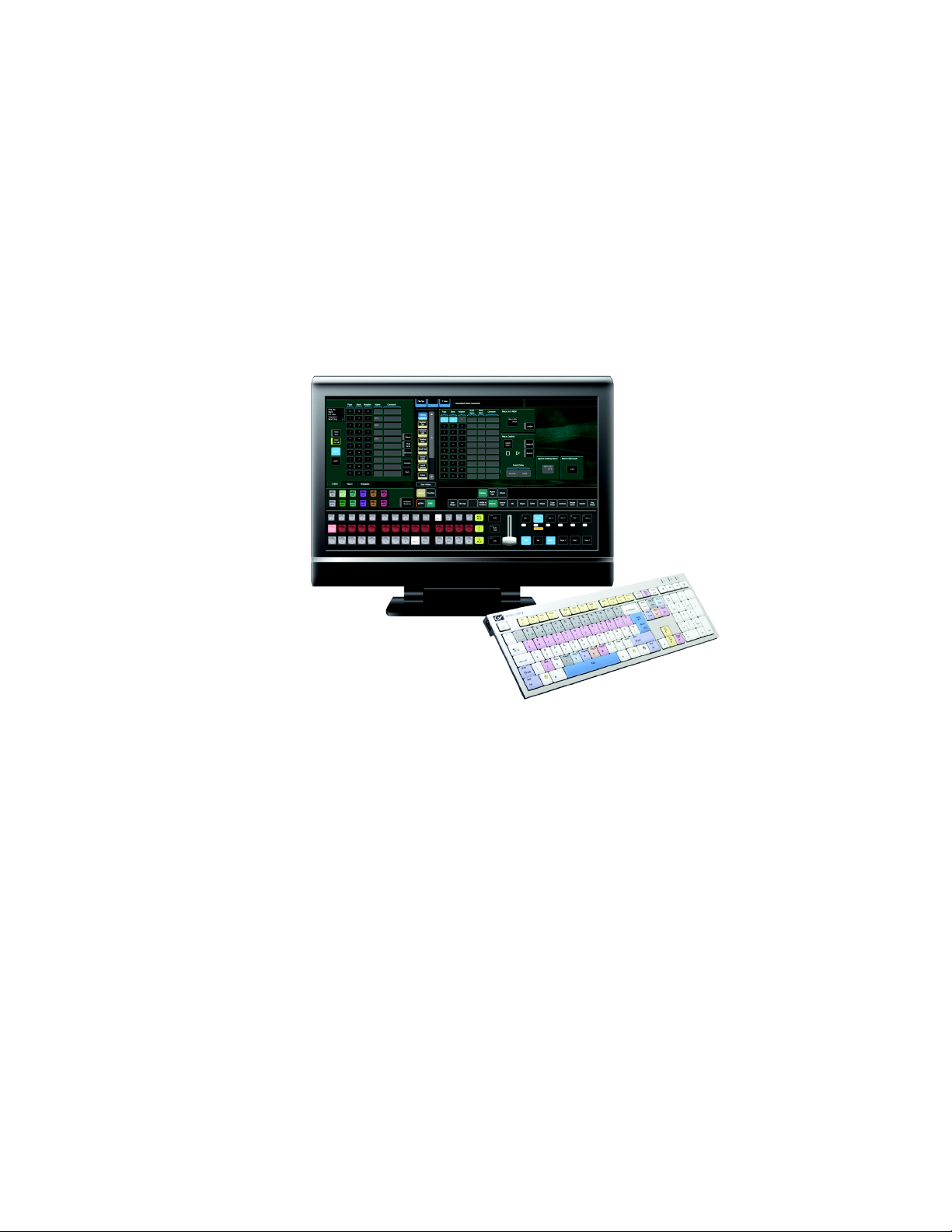
Soft Panel (KSP) Option . . . . . . . . . . . . . . . . . . . . . . . . . . . . . . . . . . . . . . . . . . . . . . 15
Menu Application . . . . . . . . . . . . . . . . . . . . . . . . . . . . . . . . . . . . . . . . . . . . . . . . . . . 16
Kayenne K-Frame System Examples . . . . . . . . . . . . . . . . . . . . . . . . . . . . . . . . . . . . . 16
Basic Single Suite Kayenne Panel System . . . . . . . . . . . . . . . . . . . . . . . . . . . . . . . 16
Multiple Suite Kayenne Panel System . . . . . . . . . . . . . . . . . . . . . . . . . . . . . . . . . . 16
Karrera K-Frame System Examples . . . . . . . . . . . . . . . . . . . . . . . . . . . . . . . . . . . . . . 17
Basic Single Suite Karrera Panel System . . . . . . . . . . . . . . . . . . . . . . . . . . . . . . . . 17
Multiple Suites and Control Surfaces. . . . . . . . . . . . . . . . . . . . . . . . . . . . . . . . . . . 18
Supported Control Protocols. . . . . . . . . . . . . . . . . . . . . . . . . . . . . . . . . . . . . . . . . . . . 19
. . . . . . . . . . . . . . . . . . . . . . . . . . . . . . . . . . . . . . . . . . . . . . . . . 7
Section 2 — K-Frame Installation
13-RU Video Processor. . . . . . . . . . . . . . . . . . . . . . . . . . . . . . . . . . . . . . . . . . . . . . . . . 21
6-RU Video Processors . . . . . . . . . . . . . . . . . . . . . . . . . . . . . . . . . . . . . . . . . . . . . . . . . 26
6RU Compact S-series Front Views with Doors Removed . . . . . . . . . . . . . . . . . 28
6RU Compact Front Views with Doors Removed . . . . . . . . . . . . . . . . . . . . . . . . 29
6RU Rear View . . . . . . . . . . . . . . . . . . . . . . . . . . . . . . . . . . . . . . . . . . . . . . . . . . . . . . . 30
K-Frame Controller Connections . . . . . . . . . . . . . . . . . . . . . . . . . . . . . . . . . . . . . . . . 30
K-Frame Standard Power Supply Frame Installation . . . . . . . . . . . . . . . . . . . . . . . 31
K-Frame Standard Power Supply Frame Rack Placement . . . . . . . . . . . . . . . . . 32
K-Frame Standard Power Supply Cooling . . . . . . . . . . . . . . . . . . . . . . . . . . . . . . 34
K-Frame Standard Power Supply AC Requirements. . . . . . . . . . . . . . . . . . . . . . 34
Supplied Power Cables for Standard K-Frame . . . . . . . . . . . . . . . . . . . . . . . . . 34
About Low Line (120V) Operational Considerations. . . . . . . . . . . . . . . . . . . . 35
About High Line (208V-240V) Verses Low Line (120V) Operations . . . . . . . 35
K-Frame Compact Power Supply AC Requirements . . . . . . . . . . . . . . . . . . . . . . . 36
About Low Line (120V) Operational Considerations . . . . . . . . . . . . . . . . . . . . . 36
About High Line (208V-240V) Verses Low Line (120V) Operations . . . . . . . . . 36
Replacing Compact Power Supplies . . . . . . . . . . . . . . . . . . . . . . . . . . . . . . . . . . . . . 37
K-Frame Video Processor Door Removal Clearance . . . . . . . . . . . . . . . . . . . . . . . . 38
. . . . . . . . . . . . . . . . . . . . . . . . . . . . . . . . . . . . . . 21
K-FRAME — Installation Planning Guide 5
Page 6

Contents
Section 3 — K-Frame Cabling
Overview . . . . . . . . . . . . . . . . . . . . . . . . . . . . . . . . . . . . . . . . . . . . . . . . . . . . . . . . . . . . 41
Network Cabling . . . . . . . . . . . . . . . . . . . . . . . . . . . . . . . . . . . . . . . . . . . . . . . . . . . . . 42
K-Frame Ethernet Tally Verses Serial Tally . . . . . . . . . . . . . . . . . . . . . . . . . . . . . 42
K-Frame Ethernet Switch. . . . . . . . . . . . . . . . . . . . . . . . . . . . . . . . . . . . . . . . . . . . . 42
Suites and Control Surfaces. . . . . . . . . . . . . . . . . . . . . . . . . . . . . . . . . . . . . . . . . . . 42
Customer Supplied Ethernet Routers and Switches . . . . . . . . . . . . . . . . . . . . . . 43
Factory Default Network Settings . . . . . . . . . . . . . . . . . . . . . . . . . . . . . . . . . . . . . 45
Video Cabling . . . . . . . . . . . . . . . . . . . . . . . . . . . . . . . . . . . . . . . . . . . . . . . . . . . . . . . . 45
Inputs . . . . . . . . . . . . . . . . . . . . . . . . . . . . . . . . . . . . . . . . . . . . . . . . . . . . . . . . . . . . . 46
Outputs. . . . . . . . . . . . . . . . . . . . . . . . . . . . . . . . . . . . . . . . . . . . . . . . . . . . . . . . . . . . 46
MatchDef and SetDef Format Conversion . . . . . . . . . . . . . . . . . . . . . . . . . . . . . . 46
Reference Input . . . . . . . . . . . . . . . . . . . . . . . . . . . . . . . . . . . . . . . . . . . . . . . . . . . . . 46
K-Frame System Video Timing and Delay . . . . . . . . . . . . . . . . . . . . . . . . . . . . . . . . 47
Time Zones and the Autotiming Window . . . . . . . . . . . . . . . . . . . . . . . . . . . . . . 48
Video Processor Frame GPI/Tally Interface . . . . . . . . . . . . . . . . . . . . . . . . . . . . . . 49
GPI and Tally Connections . . . . . . . . . . . . . . . . . . . . . . . . . . . . . . . . . . . . . . . . . . . 49
GPI Inputs. . . . . . . . . . . . . . . . . . . . . . . . . . . . . . . . . . . . . . . . . . . . . . . . . . . . . . . . 49
Tally/GPI Outputs . . . . . . . . . . . . . . . . . . . . . . . . . . . . . . . . . . . . . . . . . . . . . . . . 50
Pin Assignments . . . . . . . . . . . . . . . . . . . . . . . . . . . . . . . . . . . . . . . . . . . . . . . . . . . . . . 52
RS-422/485 Ports. . . . . . . . . . . . . . . . . . . . . . . . . . . . . . . . . . . . . . . . . . . . . . . . . . . . 52
RS-232 Ports . . . . . . . . . . . . . . . . . . . . . . . . . . . . . . . . . . . . . . . . . . . . . . . . . . . . . . . . 52
GPI In, Tally, GPI Out . . . . . . . . . . . . . . . . . . . . . . . . . . . . . . . . . . . . . . . . . . . . . . . 53
. . . . . . . . . . . . . . . . . . . . . . . . . . . . . . . . . . . . . . . . . . 41
Appendix A — Specifications
Index
. . . . . . . . . . . . . . . . . . . . . . . . . . . . . . . . . . . . . . . . . . . . . . . . . . . . . . . . . . . . . . . . . . . . . . 59
. . . . . . . . . . . . . . . . . . . . . . . . . . . . . . . . . . . . . . . . . . . 55
6 K-FRAME — Installation Planning Guide
Page 7

Introduction
Overview
The Grass Valley K-Frame family of multi-format digital production
switchers provides powerful, ground-breaking features designed to meet
the widest range of requirements for live studio, mobile, and post-produc
tion applications.
The K-Frame Video Processor is the heart of the system, providing extensive video switching and signal processing capabilities. This functionality
is controlled using:
• a Kayenne control surface,
Section
1
-
• a Karrera control surface,
• the Soft Panel (KSP option), and/or
• the Menu application running on a PC.
In addition, a K-Frame system supports direct control of external devices
(DDRs, Servers) and bi-directional control to and from routing and auto
mation systems.
-
KAYENNE K-FRAME — Installation & Service Manual 7
Page 8

Section 1 — Introduction
Features
General
• Fully digital 10-bit 4:2:2 video switcher including Future-Ready 4K and
1080p (level A or B) support.
• Optional smart I/O modules provide up/down/cross-conversion
when licensed with SetDef and MatchDef.
• Integrated Macro Builder/Editor allows users to edit macros online or
offline on a PC running the menu application.
• Optional DoubleTake™ (split M/E mode) effectively increases the
number of M/Es and adds flexibility to Suites operation while
FlexiKey™ programmable clean feed mode supports separately programmable configurations of keyers from four M/E outputs.
• Aux bus transitions for dissolves and wipes on aux bus outputs.
• Interfaces with Grass Valley routers and Kaleido Multiviewers and
their control systems.
• Optional Integrated Image Store capable of delivering up to 32 GB
storage of Stills (3,000 images) or “Movies” (a total of 50 seconds) of
1080p video.
• LDK Series and LDX Series camera control with Ethernet tally via
Connect Gateway.
• Optional integrated external ClipStore provides multiple channels of
video/key pairs for up to 10+ hours of nonvolatile video/key/audio
clip content.
• 999 macros with many new ways to recall macros from the Control
Panel.
• 1,000 E-MEM registers with Define E-MEM for fine control in creation
and editing of effects.
• Optional M/E Previewer provides a method to check and monitor any
input to an M/E.
• VDCP Ethernet connection for stadium applications.
• Ethernet tally connection for integration with external tally systems.
• Optional RGB color correction on M/E buses and aux bus outputs.
8 KAYENNE K-FRAME — Installation & Service Manual
Page 9

• Source Rules:
• Links keyers to sources.
• Settings for On/Off/Left Alone on every M/E.
• Full look-ahead preview of rules.
• Hot-swappable, front/rear removable modules and power supplies.
• Optional multiple Multiviewer capability with 5 pre-configured
layouts (maximum 14 panes per layout) with On-Air and Preview tally.
K-Frame Standard Frame
• Up to 192 inputs and 96 outputs.
• Up to 9 M/Es, accessible across two suites—by using DoubleTake this
may be increased to 18 virtual M/Es.
• Every M/E has six keyers with standard keying modes including
Chroma Key, a pool of floating 3D iDPMs, and two frame stores per
keyer—the Controller M/E cannot use floating 3D iDPMs.
Features
• 2D-DPMs (resizers) on every keyer, with 6 pairs per M/E so iDPMs can
be utilized for more complex effects.
• The Controller M/E has a complement of 6 full keyers with Chroma
Key and 2D-DPMs.
• Up to 16 iDPMs (Integrated Digital Picture Manipulators), assigned as
either floating iDPMs or within an eDPM at user’s discretion.
K-Frame Compact Frame
• Up to 80 inputs and 48 outputs.
• Up to 5 M/Es, accessible across two suites, increased to 10 virtual M/
Es by using DoubleTake.
• Every M/E has six keyers with standard keying modes including
Chroma Key, two frame stores per keyer—every keyer except for Con
troller M/E can use the pool of floating 3D iDPMs.
• 2D-DPMs (resizers) on every keyer.
• The Controller M/E has a complement of 6 full keyers with Chroma
Key and 2D-DPMs.
-
• Up to 8 iDPMs (Integrated Digital Picture Manipulators), assigned as
either floating iDPMs or within an eDPM at user’s discretion.
KAYENNE K-FRAME — Installation & Service Manual 9
Page 10
Section 1 — Introduction
8875_01r1
K-Frame 13-RU
Video Processor
K-Frame 6-RU
Video Processor
Frame Power Supply 1-RU
(For Standard K-Frame only)
Integrated Power Supplies
K-Frame Compact S-series Frame (Differences)
• Up to 6 M/Es, accessible across two suites, increased to 12 virtual
M/Es by using DoubleTake.
• Every M/E has four keyers with standard keying modes including
Chroma Key and every keyer can use the pool of floating 3D iDPMs
(Key Stores are not available).
• 2D-DPMs (resizers) on every keyer.
• Controller M/E replaced by a pair of Multiviewers with pre-configured
layouts and On-Air/Preview tally.
K-Frame Video Processor
The K-Frame Video Processor is available in two sizes, the 13RU Standard
and the 6RU Compact. The number of licensed boards present in the frame
determines the number of MEs available, as well as the number of video
inputs, outputs, GPIOs and Relay Tallies.
K-Frame Control Surfaces
Figure 1. K-Frame Video Processors
Kayenne
10 KAYENNE K-FRAME — Installation & Service Manual
A Kayenne control surface typically consists of a Control Panel, a Menu
Panel with an included articulated support arm, a Panel Control Unit
(PCU) frame, and optional Satellite Panels. This control surface has an
Page 11
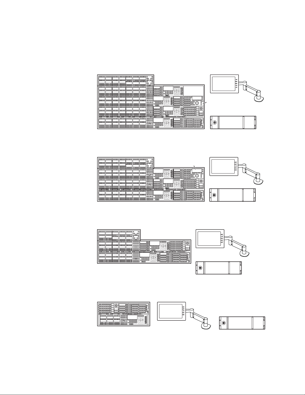
K-Frame Control Surfaces
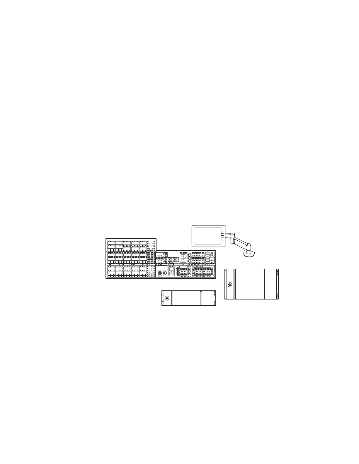
4-ME 35 Control Panel Menu Panel
Menu Panel
Articulated
Arm
8623266_01
Panel Control Unit (PCU)
Optional Device
Control Module
Optional
Module
Menu Panel
Menu Panel
Articulated
Arm
8623266_02
Panel Control Unit (PCU)
3-ME 35 Control Panel
Optional Device
Control Module
Menu Panel
Menu Panel
Articulated
Arm
8623266_04
Panel Control Unit (PCU)
1-ME 15 Control Panel
innovative modular design. Representative Kayenne control surfaces are
shown in the following illustrations.
Figure 2. Kayenne 4-ME 35 Control Surface
Figure 3. Kayenne 3-ME 35 Control Surface
Figure 4. Kayenne 2-ME 25 Control Surface
2-ME 25 Control Panel
Figure 5. Kayenne 1-ME 15 Control Surface
KAYENNE K-FRAME — Installation & Service Manual 11
Menu Panel
Menu Panel
Articulated
Arm
Panel Control Unit (PCU)
8623266_03
Page 12
Section 1 — Introduction
The modular design and use of a separate PCU supports the hot-replacement of individual Control Panel components, if necessary, while the rest
of the system remains operational.
CAUTION
Do not connect or disconnect the PCU to Control Panel cables
while the system is powered on.
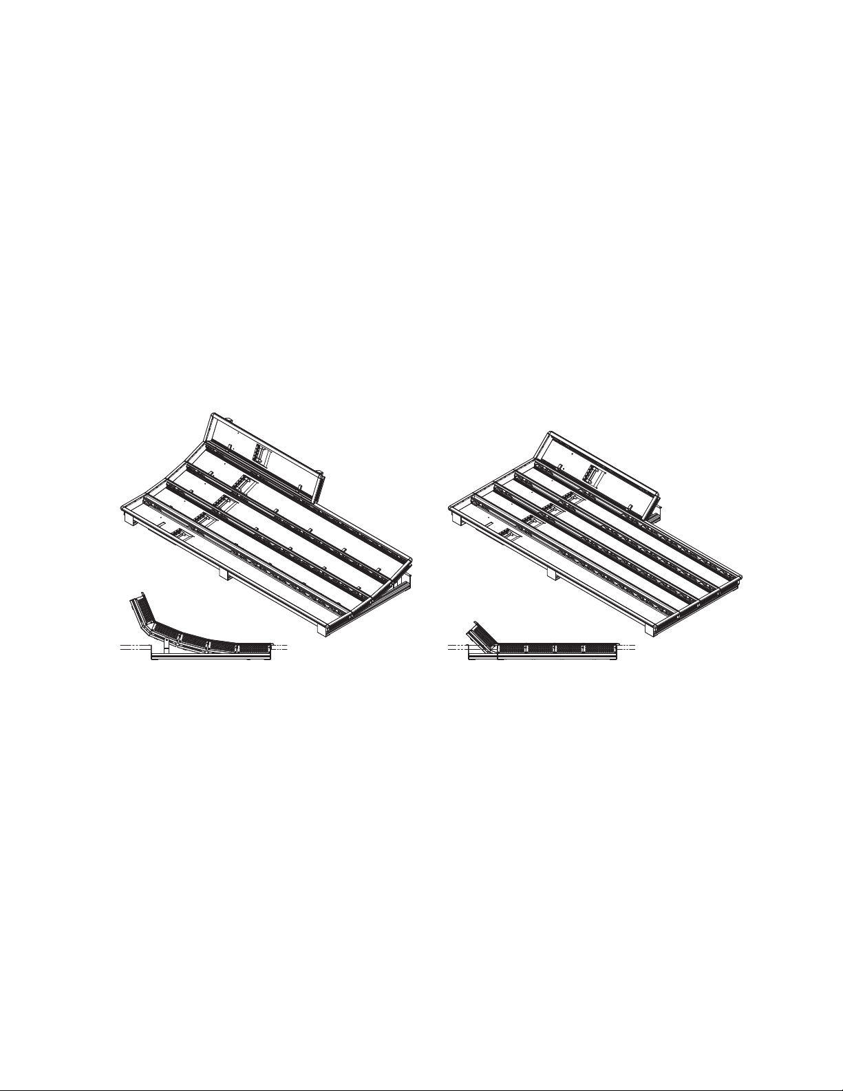
Flat or Curved Control Panel Orientation
The main Kayenne Control Panel supports different physical orientations.
Besides a conventional flat surface, a special support design permits a
curved working surface, where the MEs progressively tilt for improved
ergonomics.
Figure 6. Curved and Flat Control Surface Installations
Flat Control Panel AssemblyCurved Control Panel Assembly
12 KAYENNE K-FRAME — Installation & Service Manual
8623266_36
Page 13
Control Panel Stripes
HoldHold
HoldHold
A
HoldHold
BU1U2
HoldHold
FarFarKeyKey
SplSplit
RulesRules
HoldHold
EMEMEMEM
SecSec
Aux
Pri
KeyKey3KeyKey
1
MacroMacro
KeyKey
5
KeyKey4KeyKey
2
RtrKeKey
6
EMEMEMEM
MaMacroro
RevRev
RwdRwd
RunRun
Transans
RateRate
Auto
Run
Run
Panelnel
MemMem
MeMenu
Mix
Transns
PVW
Transans
Rate
EMEMEMEM
Runun
Ptnt n
LimLimi t
Pst
BLK
KeyKey1KeyKey2KeyKey3KeyKey4KeyKey5KeyKey
6
KeKey1
CutCut
KeKey2
CutCut
KeKey4
CutCut
KeKey3
CutCut
KeKey6
CutCut
KeKey5
CutCut
KeKey 1
Auto
Auto
KeKey 2
Auto
Auto
KeKey 3
Auto
Auto
KeKey 4
Auto
Auto
KeKey 6
Auto
Auto
CutCut AutoAuto
KeKey 5
Auto
Auto
Userer5Userer
6
Userer4Wipeipe2Wipeipe
1
Userer3Userer2Userer
1
Key
Prior
8623266_54
Source Module (35, 25, or 15) Local E-MEM ModuleTransition Module
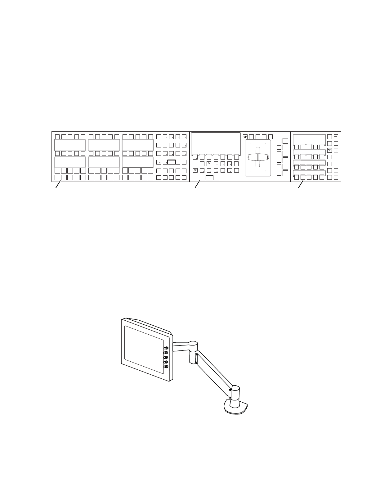
The main Kayenne Control Panel is organized into from one to five Stripes.
Each Stripe consists of a tray and its complement of drop-in modules. An
ME Stripe has a module for Source Selection, Transition, and individual
E-MEM control. Additional Master E-MEM, Machine Control, Multi-Function, and Local Aux modules are populated to complete the control surface
functionality.
Figure 7. Portion of Control Panel ME Stripe
K-Frame Control Surfaces
Touch Screen Menu Panel
Each Kayenne control surface includes a Menu Panel that features a wide
format 15 in. touch screen display. An articulated arm is also included,
offering a wide variety of installation options. The Menu Panel has a standard VESA-75 hole pattern and M4 threads, compatible with this and many
other mounting devices.
The Menu Panel has four USB ports, two on the right side edge of the panel
and two on the back for keyboard and mouse (wired or wireless are sup
ported).
Figure 8. Menu Panel with Articulated Arm
-
KAYENNE K-FRAME — Installation & Service Manual 13
8623266_05
Page 14
Section 1 — Introduction
8623266_05_Krr
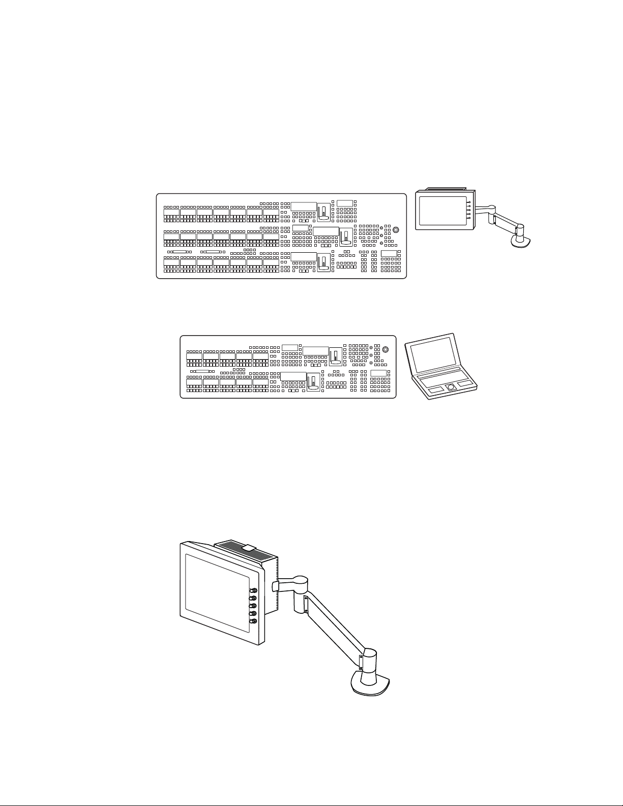
Karrera
Karrera 3-ME 35 Control Panel
A Karrera control surface typically consists of a Control Panel and a Menu
application. Representative Karrera control surfaces are shown in the fol
lowing illustrations.
Figure 9. Karrera 3-ME 35 Control Surface
Menu Panel
Articulated
Arm
Optional Touch Screen
Karrera Menu Panel with
Fanless PC
Figure 10. Karrera 2-ME 25 Control Surface
Karrera 2-ME 25 Control Panel
Karrera Menu on PC
-
8623266_02_Krr
Touch Screen Menu Panel Option
A hardware Karrera Menu Panel is available as an option, which features a
wide format 15 in. touch screen display. An articulated arm is also
included, offering a wide variety of installation options.
Figure 11. Menu Panel with Articulated Arm
(Customer Supplied PC)
8623266_03_Krr
14 KAYENNE K-FRAME — Installation & Service Manual
Page 15
The Menu Panel has a standard VESA-75 hole pattern and M4 threads,
compatible with this and many other mounting devices. The Menu Panel
also has four USB ports, two on the right side edge of the panel and two on
the back for keyboard and mouse (wired or wireless are supported).
A fanless PC, running Windows OS, is available which mounts behind the
Menu Panel.
Soft Panel (KSP) Option
Figure 12. Soft Panel Application
K-Frame Control Surfaces
The KSP is an optional 1-ME Soft Panel GUI which provides direct control
of switching crosspoints, recalling effects and macros together with an inte
grated version of the Menu application. A customized PC keyboard is
included with the option for users who like quick cut and mix action from
a hard-button interface. The KSP can be used as an adjunct to a main panel,
providing a second seat (second control surface) in a Suite, or as the only
control surface for a second Suite.
The KSP GUI application is designed to run on a PC platform. The screen
must be 1920x1080 resolution or better (which is common in professional
video environments). A touchscreen is not required, but can be very useful.
The KSP software is included with the switcher application software. Purchasing the option provides a software license that enables the interface for
the selected switcher, and includes a customized PC keyboard. The license
activates an unlimited number of KSP applications associated with the
licensed video processor frame. Additional customized PC keyboards are
also available for purchase.
-
KAYENNE K-FRAME — Installation & Service Manual 15
Page 16
Section 1 — Introduction
Menu Application
The Menu application software provided with every K-Frame system can
be run on a standard PC. This software accesses all the system’s function
ality, permitting mouse and keyboard control from a laptop, or remote
control from any location on the network.
Kayenne K-Frame System Examples
Basic Single Suite Kayenne Panel System
A basic K-Frame system consists of a Control Panel, a Menu application
running on a touch screen Menu Panel, and a Video Processor Frame. The
Control Panel and Menu application make up a control surface associated
with that frame. The Kayenne Control Panel and Menu Panel have associ
ated active electronics housed in the Panel Control Unit (PCU).
-
-
Figure 13. Kayenne Single Suite Compact Frame Example
2-ME 25 Kayenne Control Panel
Panel Control Unit (PCU)
Multiple Suite Kayenne Panel System
A K-Frame system can be subdivided into two suites, if desired, each of
which can have two control surfaces (Surface A and Surface B). Each
surface has it's own set of Panel Preferences for configuration of the control
panel behavior and independent macro systems to allow for independent
building and running of macros by each operator at the control surface.
Hardware resources in the Video Processor Frame can be assigned to an
individual suite during configuration, essentially creating two separate
switchers sharing one frame.
Menu Panel
Compact 6-RU K-Frame
8877_01
16 KAYENNE K-FRAME — Installation & Service Manual
Page 17
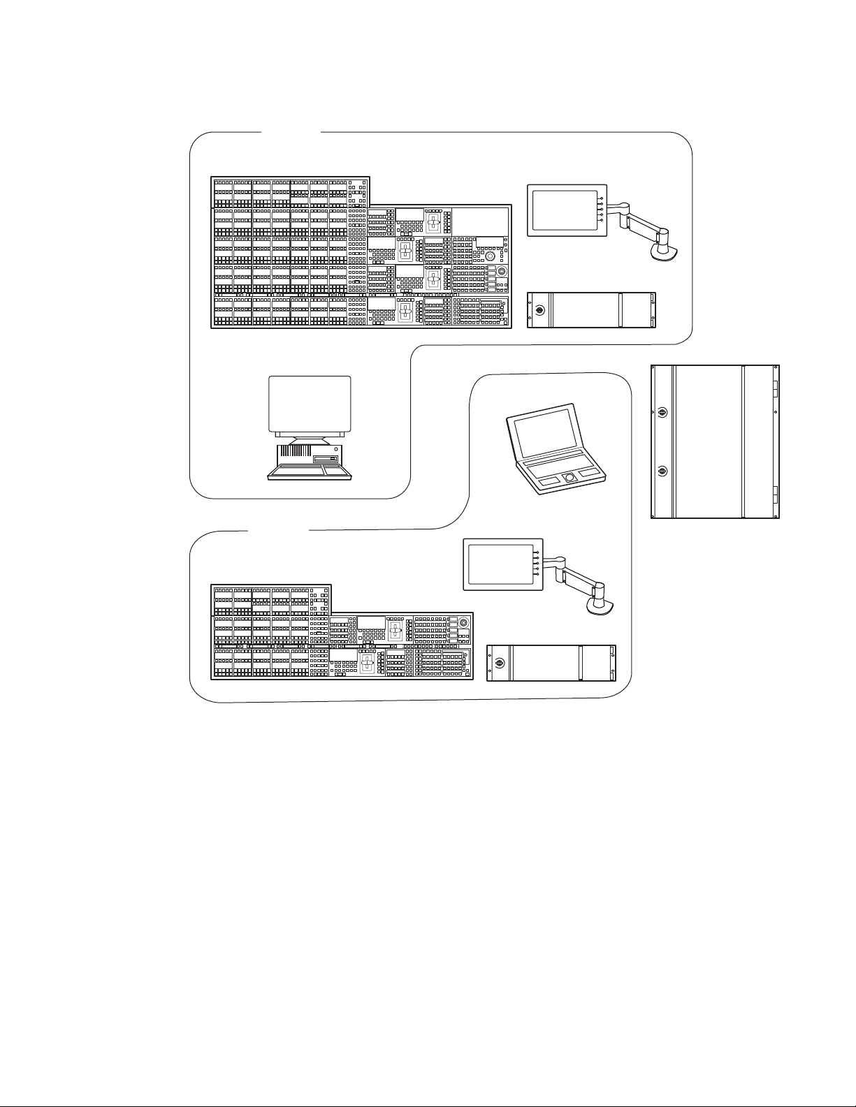
Karrera K-Frame System Examples
8875_20
Suite 1
Menu on PC
KSP 1-ME
Soft Panel Option
(Keyboard Included)
Suite 2
4-ME 35 Kayenne Control Panel
Menu Panel
Panel Control Unit (PCU)
Standard 13-RU
K-Frame
Menu Panel
Panel Control Unit (PCU)
2-ME 25 Kayenne Control Panel
(Customer Supplied PC)
(Customer Supplied PC)
Figure 14. Kayenne Multi-Suite Standard Frame Example
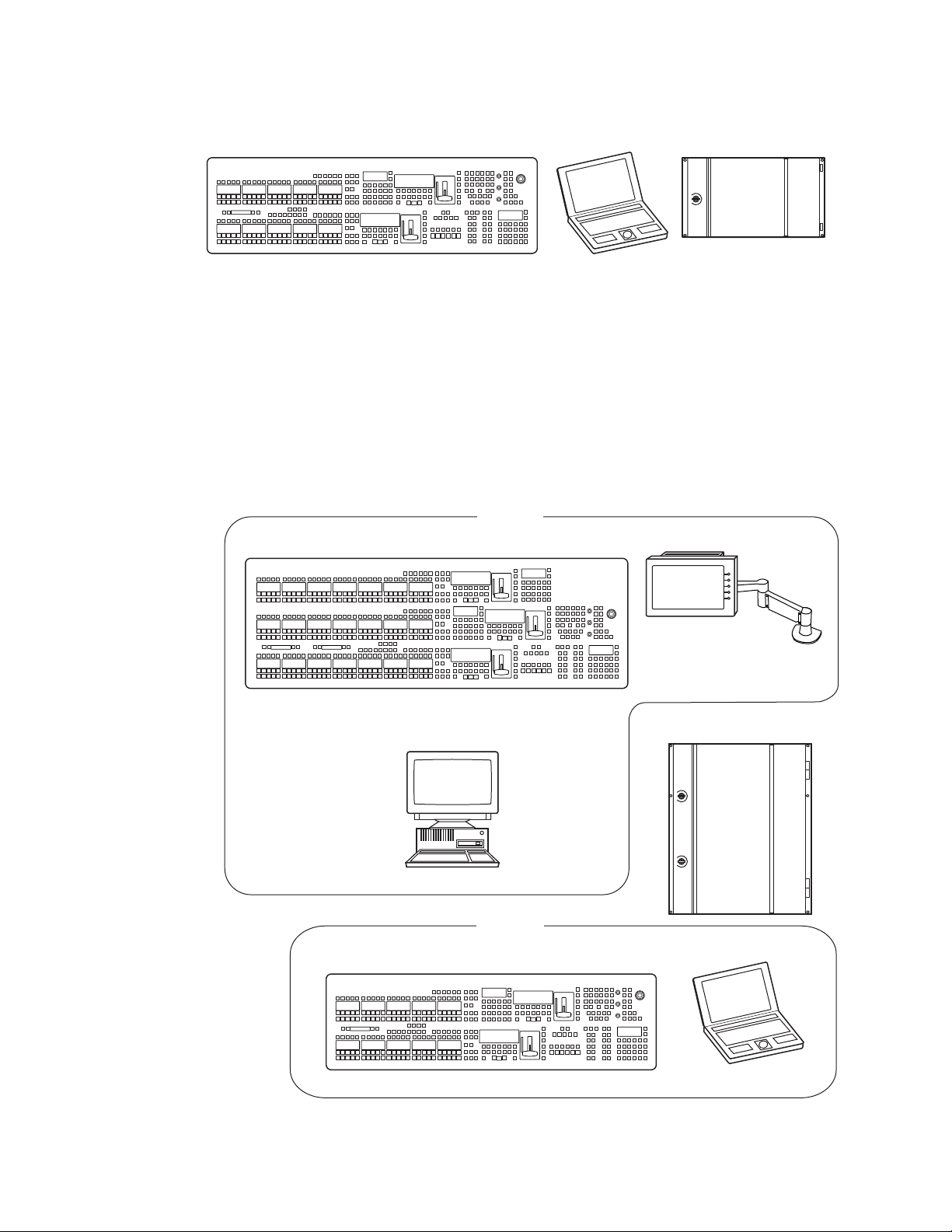
Karrera K-Frame System Examples
Basic Single Suite Karrera Panel System
A basic K-Frame system consists of a Control Panel, a Menu application
running on a PC, and a Video Processor Frame. The Control Panel and
Menu application make up a control surface associated with that frame.
KAYENNE K-FRAME — Installation & Service Manual 17
Page 18
Section 1 — Introduction
Karrera 2-ME 25 Control Panel Compact 6-RU K-Frame
Multiple Suites and Control Surfaces
Figure 15. Karrera Single Suite Compact Frame Example
Karrera Menu on PC
(Customer Supplied PC)
A K-Frame system can be subdivided into two suites, if desired, each of
which can have two control surfaces. Hardware resources in the Video Pro
cessor Frame can be assigned to an individual suite during configuration,
essentially creating two separate switchers sharing one K-Frame.
Figure 16. Karrera Multi-Suite Standard Frame Example
8875_19
-
Karrera 3-ME 35 Control Panel
(Customer Supplied PC)
Karrera 2-ME 25 Control Panel
Suite 1
KSP 1-ME
Soft Panel Option
(Keyboard Included)
Suite 2
Optional Touch Screen
Karrera Menu Panel with
with Fanless PC and
Articulated Arm
Standard 13-RU
K-Frame
Karrera Menu on PC
8878_01
(Customer Supplied PC)
18 KAYENNE K-FRAME — Installation & Service Manual
Page 19

Supported Control Protocols
• PBus II
• GPI Inputs and Outputs
• Serial BVW-75 for VTR control
• Odetics protocol for VTR control
• AMP (advanced media protocol) for Profile PVS, Profile XP Media Plat-
form, K2, M-Series, Turbo iDDR, and T2 iDDR systems over Ethernet
• Grass Valley Native Protocol for routers/routing control systems
(Trinix/Trinix NXT, Venus™, Triton™, and third-party routers; Jupiter
and Encore router control systems)
• Tally (contact closure)
• K-Frame Ethernet Tally protocol
• Ethernet CPL to control Grass Valley external remote AUX Panels
• Grass Valley Editor protocol
Supported Control Protocols
• SNMP system monitoring
• Serial and Ethernet VDCP
• LDK Series & LDX Series™ camera control with Ethernet tally via
Connect Gateway
KAYENNE K-FRAME — Installation & Service Manual 19
Page 20

Section 1 — Introduction
20 KAYENNE K-FRAME — Installation & Service Manual
Page 21

K-Frame Installation
13-RU Video Processor
Figure 1. K-Frame 13-RU Dimensions (Front View)
439 mm
17.3 in.
482 mm
19.0 in.
460 mm
18.1 in.
Section
2
577 mm
22.7 in.
8875_02
Note Mounting a K-Frame in a rack immediately below equipment that extends
forward from the rack may not provide enough clearance to completely
remove the K-Frame door. See
Clearance on page 38.
K-FRAME — Installation Planning Guide 21
K-Frame Video Processor Door Removal
Page 22

Section 2 — K-Frame Installation
442 mm
17.4 in.
8875_05
37 mm
1.5 in.
566 mm
22.3 In.
602 mm
23.7 in.
483 mm
19.0 in.
Figure 2. K-Frame 13-RU Dimensions (Top View)
22 K-FRAME — Installation Planning Guide
Page 23

Figure 3. K-Frame 13-RU Rack Mounting and Cooling Airflow
Air
Intake
(Chassis
Bottom)
Air
Intake
(Chassis
Bottom)
Rear Rack
Support
Rear Rack
Support
Air Exhaust
(Chassis Top)
8875_14
13-RU Video Processor
CAUTION K-Frame installations require the use of the provided rear rack supports.
K-FRAME — Installation Planning Guide 23
Page 24

Section 2 — K-Frame Installation
Figure 4. K-Frame 13-RU, Front View with Door Removed
Fan
Assembly
Image Store
ME D1 & D2
ME C1 & C2 ME B1 & B2
Controller
with ME
ME A1 & A2
ME D1 & D2
F5
F11F13F15F17
F12F14F16F18
F6
IMAGE STORE
F4
ME C1 & C2
CONTROLLER & ME
OFF
ON
F3
ME B1 & B2
F2
ME A1 & A2
F1
Front Slots F6 - F1 Slots F18 - F11
(Reserved for
8875_03
future use.
CAUTION The Video Processor front door must remain in place and closed during
normal system operation to maintain maximum cooling efficiency.
24 K-FRAME — Installation Planning Guide
Page 25

Figure 5. K-Frame 13-RU, Rear View
R11
Mod I/O 1
Mod I/O 2
R12
Mod I/O 4
R14
Mod I/O 6
R16
Mod I/O 8
R18
R13
Mod I/O 3
R15
Mod I/O 5
R17
Mod I/O 7
R2
OUTPUTS
17 - 32
R1
OUTPUTS
1 - 16
R5
INPUTS
65 - 96
R4
INPUTS
33 - 64
R3
INPUTS
1 - 32
R10
OUTPUTS
49 - 64
R9
OUTPUTS
33 - 48
R8
INPUTS
129 - 160
R7
INPUTS
97 - 128
R6
CONTROL I/O
CAUTION
Turn off power before removing or
installing Control I/O in slot R6.
OUTPUTS
16 15 14 13 12 11 10 9
8 7654321
OUTPUTS
16 15 14 13 12 11 10 9
8 7654321
TALLY/GPI
INPUTS
32 31 30 29 28 27 26 25 24 23 22 21 20 19 18 17
16 15 14 13 12 11 10 9 8 7654321
TALLY/GPI
INPUTS
32 31 30 29 28 27 26 25 24 23 22 21 20 19 18 17
16 15 14 13 12 11 10 9 8 7654321
TALLY/GPI
INPUTS
32 31 30 29 28 27 26 25 24 23 22 21 20 19 18 17
16 15 14 13 12 11 10 9 8 7654321
TALLY/GPI
INPUTS
32 31 30 29 28 27 26 25 24 23 22 21 20 19 18 17
16 15 14 13 12 11 10 9 8 7654321
TALLY/GPI
INPUTS
32 31 30 29 28 27 26 25 24 23 22 21 20 19 18 17
16 15 14 13 12 11 10 9 8 7654321
OUTPUTS
16 15 14 13 12 11 10 9
8 7654321
OUTPUTS
16 15 14 13 12 11 10 9
8 7654321
INPUT
OUTPUT
4321 4321
INPUT
OUTPUT
4321 4321
INPUT
OUTPUT
4321 4321
INPUT
OUTPUT
4321 4321
INPUT
OUTPUT
4321 4321
INPUT
OUTPUT
43 21 43 21
INPUT
OUTPUT
43 21 43 21
INPUT
OUTPUT
43 21 43 21
DC IN
LINK/ACTIVITY
OFF-10/AMBER-100/GREEN-1000
LAN
IMAGE STORE
MULTI
VIEWER
ANALOG
REFERENCE
DIAGNOSTIC
MODE
8
7
6
5
4
3
2
246
135
1
SERIAL PORTS RS422/485
Output Video
(16 pairs of identical
outputs each)
Up to 4 modules
Modular I/O
Up to 8 modules
Module 1
Module 8
Control I/O
(DC power in,
Reference,
Ethernet and
Serial ports)
Input Video
(32 inputs,
8 GPI in/out, and 24 Tally)
Up to 5 modules
Rear Slots R1 - R10 Slots R11 - R18
13-RU Video Processor
K-FRAME — Installation Planning Guide 25
Page 26

Section 2 — K-Frame Installation
6-RU Video Processors
Figure 6. K-Frame 6-RU Dimensions (Front View)
264 mm
10.4 in.
482 mm
19.0 in.
460 mm
18.1 in.
439 mm
17.3 in.
8875_06
Note Mounting a K-Frame in a rack immediately below equipment that extends
forward from the rack may not provide enough clearance to completely
remove the K-Frame door. See
Clearance on page 38.
K-Frame Video Processor Door Removal
26 K-FRAME — Installation Planning Guide
Page 27

Figure 7. K-Frame 6-RU Dimensions (Top View
442 mm
17.4 in.
8875_09
596 mm
22.0 In.
559 mm
23.5 in.
483 mm
19.0 in.
37 mm
1.5 in.
6-RU Video Processors
K-FRAME — Installation Planning Guide 27
Page 28

Section 2 — K-Frame Installation
Figure 8. K-Frame 6-RU Rack Installation and Cooling Airflow
Rear Rack
Support
Air
Exhaust
Rear Rack
Support
Air
Intake
8875_13
CAUTION K-Frame installations require the use of the provided rear rack supports.
6RU Compact S-series Front Views with Doors Removed
The Compact S-series Frame includes four keyers per ME and two Multiviewers on the Controller board.
28 K-FRAME — Installation Planning Guide
Page 29

6-RU Video Processors
F3
ME B
F4
IMAGE STORE
F2
CONTROLLER
F1
ME A
ON
OFF
8875_23
Front Slots
F1 - F4
Fan
Assembly
ME A
Controller
ME B
F3
ME B
F4
IMAGE STORE
F2
CONTROLLER
F1
ME A
ON
OFF
Front Slots
F1 - F4
Fan
Assembly
ME A
Image Store
Controller
ME B
Figure 9. K-Frame Compact S-series 6-RU, Front View with Door Removed
6RU Compact Front Views with Doors Removed
The Compact Frame includes optionally, an Image Store board and six
keyers per ME.
Figure 10. K-Frame Compact Performance Frame 6-RU, Front View with Door Removed
CAUTION The Video Processor front door must remain in place and closed during
normal system operation to maintain maximum cooling efficiency.
K-FRAME — Installation Planning Guide 29
Page 30

Section 2 — K-Frame Installation
8875_08r1
Output Video
(16 outputs)
Up to 2 modules
Module 4 Module 1
Modular I/O
Up to 4 modules
Control I/O
(Reference,Ethernet
and Serial ports)
Input Video
(32 inputs,
8 GPI in/out, and 24 Tally)
Up to 2 modules
Power Supply
AC
6RU Rear View
Figure 11. K-Frame 6-RU, Rear View
K-Frame Controller Connections
LEDs (15)
Figure 12. K-Frame Controller Board, Inside Chassis
USB
(two ports, usable
with door closed)
NOTE: Ports and indicators here are intended only for diagnostic and service procedures.
Power
Switch
OFF
ON
RS-232
VGA
PS2
Keyboard
USB
(two ports)
Boot Mode
DIP Switch
Reset
Button
Test Points
with LEDs (9)
and Text Display
8875_10
30 K-FRAME — Installation Planning Guide
Page 31

K-Frame Standard Power Supply Frame Installation
LINK/ACTIVITY
OFF-10/AMBER-100/GREEN-1000
LAN
ANALOG
REFERENCE
DIAGNOSTIC
MODE
8
7
6
5
4
3
2
246
135
1
SERIAL PORTS RS422/485
8875_18r1
Illuminated LED indicates
Port 1 is in diagnostic mode
Reference
Serial Ports (8)
RS422/486
Ethernet (6)
(communications)
Figure 13. Controller I/O Connections, Rear of Chassis
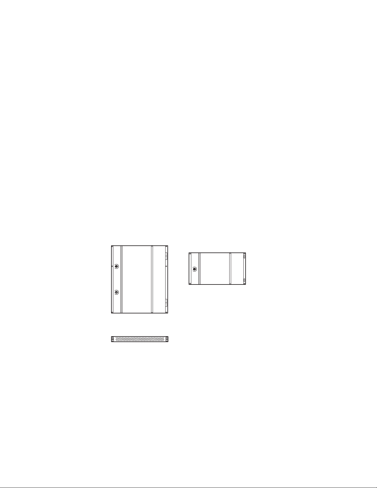
K-Frame Standard Power Supply Frame Installation
A 1-RU Power Supply Frame provides DC power for the Standard, 13RU
K-Frame Video Processor.
Figure 14. K-Frame 13RU Power Supply Frame Dimensions (Front and Rear Views)
Front View with Cover
482 mm
19.0 in.
44 mm
1.72 in.
Front View Cover Removed
Rear View
38 mm
1.5 in.
45 mm
1.8 in.
79 mm
3.1 in.
Grounding Lug
217 mm
8.5 in.
Power Modules (up to 3)
AC Input IEC C19 (3)
DC Power Out
(to K-Frame)
159 mm
6.3 in.
97 mm
3.8 in.
8875_11
36 mm
1.4 in.
K-FRAME — Installation Planning Guide 31
Page 32

Section 2 — K-Frame Installation
Figure 15. K-Frame 13RU Power Supply Frame Dimensions (Top View)
442 mm
17.4 in.
466 mm
18.3 in.
449 mm
17.7 in.
265 mm
10.4 in.
8875_15
448 mm
17.6 in.
483 mm
19.0 in.
K-Frame Standard Power Supply Frame Rack Placement
The K-Frame power supply frame is ideally rack mounted immediately
above the Standard Video Processor chassis. The power supply frame is
then supported by the lower chassis and eliminates the need for power
supply rear rack supports.
490 mm
19.2 in.
41 mm
1.6 in.
32 K-FRAME — Installation Planning Guide
Page 33

K-Frame Standard Power Supply Frame Installation
Air
Intake
Rear Rack
Support
Air
Exhaust
8875_14
Rear Rack
Support
Figure 16. Standard K-Frame Power Supply Rack Installation and Cooling Airflow
Air
Exhaust
Power Supply
Frame
Air
Intake
K-Frame
Chassis
8875_21
In addition, this placement allows removal of the front door of the K-Frame
K-Frame Video Processor Door Removal Clearance on page 38).
(see
If the power supply frame is not mounted above the K-Frame chassis, rear
rack supports are required. If mounting in an alternative location, allow for
the 34” DC interconnect cable length.
Figure 17. Isolated K-Frame Standard Power Supply Rack Installation
K-FRAME — Installation Planning Guide 33
Page 34

Section 2 — K-Frame Installation
8875_22
K-Frame Standard Power Supply Cooling
The top surface of the rear of the K-Frame Power Supply Frame has air
holes and is slightly recessed, which permits air flow even if equipment is
mounted in the rack directly above. These top recessed air holes must
remain open for proper cooling. Ensure paper or other obstructions do not
block these air holes.
K-Frame Standard Power Supply AC Requirements
The K-Frame Power Supply Frame has provision to support up to three hot
swappable power modules. These convert the AC line input to 48V DC for
the Video Processor Frame. The cells for the three modules (referred to as
left, center, right) are identical and any or all cells can have a module
installed. Each cell has its own AC line cord. The supplies are power factor
corrected and automatically accommodate low line (120V nominal) or high
line (240V nominal). The power supply frame has a rating of 100 – 240 volts,
although it is designed and tested for a range of 90 to 264 volts to accom
modate under and over voltage conditions. A Compact K-Frame is supplied with one power module. A second power module can be fitted as a
redundant power supply option. A Standard K-Frame is supplied with two
power modules. A third power module can be fitted as a redundant (n+1)
power supply option.
-
Supplied Power Cables for Standard K-Frame
The K-Frame Power Supply Frame has IEC C19 sockets, instead of the more
common C13 style, to accommodate potentially higher currents. Cables
provided with K-Frame systems are matched to the destination country’s
standard. For example, in the USA C19 to NEMA 5-20P cables are pro
vided.
Figure 18. USA Power Cable Example
-
34 K-FRAME — Installation Planning Guide
Page 35

K-Frame Standard Power Supply Frame Installation
About Low Line (120V) Operational Considerations
If low line (120V) operation is used (mostly in North America) three characteristics of the switcher should be kept in mind when provisioning AC
power for the system, which will result in the most reliable system possible:
• Consider brown-out—Modern switching power supplies are constant
power devices and as such, unlike resistive loads, the input current
increases as the input voltage decreases.
• Consider power supply failure—If two or three power modules are
present, they will load share. For instance, if two modules are fitted and
the total AC line current is 10 amps, each of the two line cords will draw
about 5 amps. If one supply fails, the other supply takes up the entire
load. At this point, one line cord will draw 0 amps and the other cord
will draw 10 amps.
• Consider future options—The total AC power consumption is significantly influenced by the number and type of hardware options
installed. This includes the number of MEs, Inputs, Outputs, and
Modular I/Os.
About High Line (208V-240V) Verses Low Line (120V) Operations
North American users usually have a choice to use low line (120 volts) or
high line (208-240 volts) as the AC source. If Lo line is used, a Standard
(13RU) K-Frame with all options installed and running at 120 volts will
draw a total of approximately 12 amps from the line cords. At 100 volts, this
increases to approximately 14 amps. This load will be evenly distributed
among the line cords. However, if one or more power supplies go offline, it
is possible for the entire 12 – 14 amps to be drawn by one line cord. For this
reason, it is recommended that each line cord be serviced by a dedicated 20
amp circuit. If this circuit is shared by other loads, consider what will
happen if the switcher line cord suddenly doubles (or triples) its current
consumption.
One 20 amp circuit is adequate to service the two or three K-Frame line
cords since the total current never exceeds 14 amps. The only disadvantage
is the reduced redundancy using one branch circuit instead of multiple cir
cuits. In a three phase WYE distribution system, additional protection can
be achieved by using different phases for each of these circuits.
The possibility of drawing as much as 14 amps from a line cord explains the
20 amp (NEMA 5-20P) plug on the line cords supplied. The NEC in the US
specifies that the ubiquitous 15 amp outlet be de-rated to 12 amps for con
tinuous loads. A 20 amp outlet is needed for the rare case of a 14 amp load
experienced during a fault condition.
-
-
Most of the above is not an issue if high line (240V) operation is used. Since
AC line currents are approximately half of those at low line, exceeding the
current rating of a circuit should not be a problem. In areas where there is
K-FRAME — Installation Planning Guide 35
Page 36

Section 2 — K-Frame Installation
a choice between high line or low line operation, the user should consider
the advantages and disadvantages of each power sourcing scheme.
K-Frame Compact Power Supply AC Requirements
The K-Frame chassis has provision to support up to two hot swappable
power modules. These convert the AC line input to 48V DC for the Video
Processor Frame. The cells for the two modules (referred to as left and
right) are identical and either or both cells can have a module installed.
Each cell has its own AC line cord. The supplies are power factor corrected
and automatically accommodate low line (120V nominal) or high line
(240V nominal). The power supplies have a rating of 100 – 240 volts,
although it is designed and tested for a range of 90 to 264 volts to accom
modate under and over voltage conditions. A Compact K-Frame is supplied with one power module. A second power module can be fitted as a
redundant power supply option.
-
About Low Line (120V) Operational Considerations
If low line (120V) operation is used (mostly in North America) three characteristics of the switcher should be kept in mind when provisioning AC
power for the system, which will result in the most reliable system possible:
• Consider brown-out—Modern switching power supplies are constant
power devices and as such, unlike resistive loads, the input current
increases as the input voltage decreases.
• Consider power supply failure—If two or three power modules are
present, they will load share. For instance, if two modules are fitted and
the total AC line current is 10 amps, each of the two line cords will draw
about 5 amps. If one supply fails, the other supply takes up the entire
load. At this point, one line cord will draw 0 amps and the other cord
will draw 10 amps.
• Consider future options—The total AC power consumption is significantly influenced by the number and type of hardware options
installed. This includes the number of MEs, Inputs, Outputs, and
Modular I/Os.
About High Line (208V-240V) Verses Low Line (120V) Operations
North American users usually have a choice to use low line (120 volts) or
high line (208-240 volts) as the AC source. If Lo line is used, a Compact
K-Frame with all options installed and running at 120 volts will draw a
total of approximately 9 amps from the line cords. At 100 volts, this
increases to approximately 10 amps. This load will be evenly distributed
36 K-FRAME — Installation Planning Guide
Page 37

among the line cords. However, if one or more power supplies go offline, it
is possible for the entire 10 amps to be drawn by one line cord. For this
reason, it is recommended that each line cord be serviced by a dedicated 20
amp circuit. If this circuit is shared by other loads, consider what will
happen if the switcher line cord suddenly doubles its current consumption.
One 20 amp circuit is adequate to service the two K-Frame line cords since
the total current never exceeds 10 amps. The only disadvantage is the
reduced redundancy using one branch circuit instead of multiple circuits.
Most of the above is not an issue if high line (240V) operation is used. Since
AC line currents are approximately half of those at low line, exceeding the
current rating of a circuit should not be a problem. In areas where there is
a choice between high line or low line operation, the user should consider
the advantages and disadvantages of each power sourcing scheme.
Replacing Compact Power Supplies
Replacing Compact Power Supplies
Compact K-Frame Video Processors come with one power supply with the
option of a second, located in the front of the chassis. Power supplies are
hot swappable in systems containing two power supplies.
CAUTION ESD equipment and procedures should be used when servicing electronic
components.
Remove the power supply.
1.
Open the front door of the Compact K-Frame.
2.
Locate the lock and lock screw, located in the front, lower middle of the
power supply labeled OPEN and LOCKED.
K-FRAME — Installation Planning Guide 37
Page 38

Section 2 — K-Frame Installation
7504_01
Lock Screw
Power Supply
Lock
Figure 19. Compact Frame Power Supply Lock Screw
3.
Loosen the lock screw a few turns to the left, using a Phillips head
screwdriver.
4.
Slide the lock toward the OPEN label (left) and pull the power supply
straight out of the chassis.
Replace the power supply.
1.
Slide the replacement power supply straight in and make sure the lock
is in the LOCKED position.
2.
Tighten the lock screw to the right, just until tight.
3.
Close the Compact K-Frame door, making sure that it latches in the
closed position.
K-Frame Video Processor Door Removal Clearance
CAUTION The Video Processor front door must remain in place and closed during
normal system operation to maintain maximum cooling efficiency.
The K-Frame Video Processor door on all K-Frames can be completely
removed when installed in a rack immediately below conventional flush
mounted rack-ear only equipment. If the Standard K-Frame power supply
Frame is mounted directly above the Standard K-Frame chassis, the chassis
door can be completely removed after removing the power supply’s front
screen. However, mounting any K-Frame (including Compact Performance
and Compact S-series) in a rack immediately below other equipment that
38 K-FRAME — Installation Planning Guide
Page 39

K-Frame Video Processor Door Removal Clearance
extends forward from the rack (for example, under another K-Frame
chassis) may not provide enough clearance to remove the K-Frame door.
If mounted below equipment that extends forward from the rack, allow at
least 24 mm (0.94 in.) of vertical clearance above the K-Frame to permit
door removal. A flush design 1 RU blank filler panel can be used for clear
ance, if required.
-
K-FRAME — Installation Planning Guide 39
Page 40

Section 2 — K-Frame Installation
40 K-FRAME — Installation Planning Guide
Page 41

K-Frame Cabling
8875_16
Operator’s
Laptop
Disable Internet or
Wireless Connections
Isolate Switcher System from External Network
Internal Control
K-Frame Video Processor
Video
Processor
CPU
Image Store
Ehternet Switch
1
2
3
4
5
6
7
8
Menu
PC
Menu Panel
Remote Aux Panel
Remote Aux Panel
Clip Store
Facility LAN
Switch
Switcher Control Panel
USB (4)*
Keyboard, VGA*
RS-232*
RS-422/485 (8)
GPI In/Out
Tally
USB
DVI-D
Ethernet
Serial Control
VGA
Ethernet
(100m / 300ft max single hop length,
unlimited distance using switches)
Overview
A K-Frame Video Processor uses Ethernet for basic system communications, can operate with Kayenne or Karrera control surfaces, supports
several video inputs and output standards, and has other available inter
faces (RS-232, Tally, GPI).
Note Specific Kayenne and Karrera control surface cabling information is provided
in each product’s separate documentation sets. One important difference is
Kayenne systems i ncorporate the Menu PC and Control Panel electronics into
a Panel Con
trol Unit (PCU) chassis,
Section
3
-
Figure 1. K-Frame System Communications Overview
CAUTION The facility network used for your K-Frame system (and other video produc-
tion equipment) should be kept separate from any external network, to
prevent network traffic from adversely affecting K-Frame system operation.
K-FRAME — Installation Planning Guide 41
Page 42

Section 3 — K-Frame Cabling
Network Cabling
Network connections are required between the K-Frame Video Processor,
Control Panels, and Menu Panel PC.
K-Frame Ethernet Tally Verses Serial Tally
Our K-Frame tally system provides significantly more information than the
bandwidth of the serial connection. Therefore, we support Ethernet tally
only. However, many tally vendors do support our Ethernet tally system so
contact your tally vendor for K-Frame Ethernet tally support information.
K-Frame Ethernet Switch
The Ethernet switch built into the K-Frame auto-detects speed and polarity,
and is 10/100/1000 Mbps capable. Either straight-through or crossover
Ethernet cabling can be used. Available Ethernet connectors may be con
nected to the Facility LAN or other devices, as needed. However, should
the K-Frame power down, the internal Ethernet switch will also power
down, interrupting communication to devices connected to that Frame’s
internal Ethernet switch. Only connect devices that are K-Frame system
related.
-
Suites and Control Surfaces
A K-Frame system can be divided into two suites. K-Frame system
resources (MEs, eDPMs, external devices, etc.) can be assigned to each
suite, creating two switchers with one K-Frame system. Each suite can be
subdivided into two control surfaces. These control surfaces can be located
anywhere on the network, permitting system control from different rooms,
floors, or even different buildings. Two dedicated, customer supplied
Ethernet switches may be required when multiple suites are being used.
42 K-FRAME — Installation Planning Guide
Page 43

Figure 2. Two Suite K-Frame System
8875_17
Suite Boundary
Ethernet
Ethernet
(100m / 300ft max single hop length,
unlimited distance using switches)
Operator’s
Laptop
Menu
PC
Menu Panel
Switcher Control Panel, Suite 1
USB
DVI-D
Operator’s
Laptop
Switcher Control Panel, Suite 2
Ethernet LAN
Switch
Isolate Switcher System from External Network
Remote Aux Panel
Remote Aux Panel
Clip Store
Facility LAN
Switch
Ethernet LAN
Switch
Internal Control
K-Frame Video Processor
Video
Processor
CPU
Image Store
Ehternet Switch
7
8
1
2
3
4
5
6
USB (4)*
Keyboard, VGA*
RS-232*
RS-422/485 (8)
GPI In/Out
Tally
Suite 1
Suite 2
Network Cabling
Customer Supplied Ethernet Routers and Switches
Existing facility Ethernet switches can be used in conjunction with a
K-Frame system. If connecting to a network area outside that used by the
K-Frame system, use of an appropriately configured Ethernet Router is
strongly advised. This reduces network traffic on the K-Frame network and
keeps it isolated. Any Ethernet switches added specifically for use with the
K-Frame system should be 1000 Mbps capable for the most efficient opera
tion.
-
K-FRAME — Installation Planning Guide 43
Page 44

Section 3 — K-Frame Cabling
Table 1. Customer Provided Equipment Ethernet Specifications
Cables
Switch
Typ e
Connectors
Length
Speed
Ports
Unmanaged
Managed
10BaseT, 100BaseT, 1000BaseT compatible.
Category 5 cable, 8 conductor twisted pair.
The system will work at lower ratings with reduced performance.
1000BaseT components are highly recommended.
RJ-45 male connector at each end of cable.
10BaseT, 100BaseT, 1000BaseT: 328 ft. (100 m) maximum.
Use additional switches to exceed maximum cable runs.
10/100/1000 Mbps
RJ-45 auto-negotiating 10/100/1000 Mbps; number of ports required
is dependent upon system size. Frame ports are capable of 1000 Mbps.
Using a 1000 Mbps Ethernet switch enhances Image Store transfer
speeds.
Recommended. Configuration not required, but does not provide
remote monitoring capability.
May be used. Requires configuration, but offers remote monitoring
capability.
44 K-FRAME — Installation Planning Guide
Page 45

Factory Default Network Settings
Table 2. K-Frame System Default IP Addresses
Device IP Address
K-Frame Video Processor CPU 192.168.0.170
Image Store CPU 192.168.0.171
Control Panel Surface 1A 192.168.0.173
Touch Screen Menu Panel 1 192.168.0.175
Touch Screen Menu Panel 2 192.168.0.176
Control Panel Surface 1B 192.168.0.177
Control Panel Surface 2A 192.168.0.178
Control Panel Surface 2B 192.168.0.179
32-Crosspoint Remote Aux Panels
V1.6.5 and higher software:
(hard reset with the front panel buttons)
All Subnet Masks) 255.255.255.0
All Gateways
(except V1.6.5 software Remote Aux panel)
Reserved For Future Use
Video Processor Frame Gigabit Ethernet
Reserved LAN Port
IP Address: 192.168.1.2
Frame IP: 192.168.1.1
Gateway IP: 192.168.1.1
Subnet Mask 255.255.255.0
Note
192.168.0.1
CAUTION
192.168.0.172
192.168.0.174
32-Crosspoint Remote Aux Panel default settings must
be changed to operate with other system components
that are configured with their default IP addresses.
Do not connect any devices configured with the following IP addresses to a K-Frame network.
Video Cabling
Video Cabling
Note Customer orders with multiple Control Panels will be pre-configured to the
listed IP addresses. However, if one of these additional Control Panels is reset
to factory defaults, it will be given the standard 1A default 192.168.0.173
address.
To integrate K-Frame system devices into an existing network, ask the local
network administrator for that network’s subnet mask. Before changing IP
addresses always set the subnet masks of the devices to the mask of the
local network.
All K-Frame system video inputs and outputs are configurable. For cabling
configuration flexibility, each external primary input can be mapped to any
control panel source select bu tto n, as can each inte rna l vid eo sy ste m sou rce.
Any K-Frame system video signal, such as ME program, preview, clean
feed, or PGM/PST, can be mapped to any output bus to be sent to any
output connector, or an output bus can act as an auxiliary bus.
K-FRAME — Installation Planning Guide 45
Page 46

Section 3 — K-Frame Cabling
Inputs
Non-looping video inputs on the back of the Video Processor Frame are
numbered 1 through 32 on each input module. Each accepts a 270 MHz,
1.485 GB, or 3 GB serial digital video signal.
Outputs
Paired outputs on the back of the Video Processor Frame are numbered 1
through 16 on each output module. Identical signals are present on each of
the paired output connectors. All of the outputs carry the same video
format, as determined by the selected video standard.
MatchDef and SetDef Format Conversion
K-Frame Video Processor modular IO is available for MatchDef and SetDef
signal conversion, or to increase the number of standard video inputs and
outputs. This functionality is configurable in software. The 13-RU Standard
K-Frame can hold up to eight modules, and the 8-RU can hold up to four.
Each modular I/O module has four pairs of connectors, labeled IN 1-4 and
OUT 1-4. The connectors with the same number on that module constitutes
a configurable pair. Three different software settings are available for each
pair of modular I/O connectors:
Tab l e 3.
Bypass Input connector receives normal video.
MatchDef Input connector has a configurable MatchDef scaler
SetDef Input connector receives normal video.
Reference Input
The K-Frame Video Processor has one analog looping reference input,
which can be used with any SD/HD/3G standard. This reference input
signal must have the same frame rate as the native operating standard of
the K-Frame.
Setting Connector Function
Output connector is a normal Aux bus.
Output connector is a normal Aux bus.
Output connector has a configurable SetDef scaler
75-ohm termination of the looping input is required, either directly on the
adjacent connector or at the end of a daisy chain looping to other equip
ment.
46 K-FRAME — Installation Planning Guide
-
Page 47

K-Frame System Video Timing and Delay
Nominal Output
Timing
Serial Input
Autotiming
Window
+/- B µs
Nominal Reference
Timing
8096_03_05_r1
Nominal Switcher Delay
A µs
Maximum Switcher Delay
D µs
Minimum Switcher Delay
C µs
- B µs + B µs0 µs
Alternatively, any one of the K-Frame video inputs can also be used as reference in the respective standard.
K-Frame System Video Timing and Delay
The total delay of a video input to the switcher output can vary according
to the relationship of the input to the switcher reference. The switcher will
automatically autotime inputs that fall within an autotiming window.
Inputs must be within this range to be properly timed at the output. The
calculation of the actual video delay of a specific input is the Nominal
Switcher Delay minus the input time location within the autotiming
window (the time location value can be zero, positive, or negative).
Figure 3. Switcher Timing Diagram
• For inputs entering the switcher in zero time with the reference, the
total delay through the switcher is the Nominal Switcher Delay (A
• Inputs that reach the switcher at the latest point in the autotiming
window (+B μs) will have a total delay that equals the time required for
switcher processing. This value is the Minimum Switcher Delay (C μs).
• Inputs that reach the switcher at the earliest point in the autotiming
window (-B μs) will have a total delay equal to the Nominal Switcher
Delay (A μs) plus the autotiming window range. This value is the
Maximum Switcher Delay value (D μs).
On K-Frame systems the autotiming window varies depending on the
operating mode. The Timing Analyzer in the Video Settings Menu displays
this autotiming information.
K-FRAME — Installation Planning Guide 47
Note The maximum switcher delay is approximately one line of video.
μs).
Page 48

Section 3 — K-Frame Cabling
Time Zones and the Autotiming Window
Each ME has a fixed amount of delay from its input to output. To allow
reentries to remain in time, ME timings are staggered such that the up
stream ME outputs are in time (or earlier) than down stream ME inputs. A
5 ME production switcher has six time zones to accommodate reentry
through all the MEs to any output. When all MEs are cascaded into each
other, the most up stream ME is in the earliest time zone. Aux buses and
other outputs are always in the latest time zone. The overlapping range of
all the autotimers is the published autotiming window for the switcher.
Figure 4. Production Switcher Time Zones
Time
Zone
1
Time
Zone
2
Time
Zone
3
Autotiming Range
Autotiming Range
Time
Zone
4
Time
Zone
Autotiming Range
5
Autotiming Range
Time
Zone
6
M/E
Processing
Delay
Autotiming Range
M/E
Processing
Delay
Autotiming Range
M/E
Processing
Delay
M/E
Processing
Delay
M/E
Processing
Delay
Aux
Output
Delay
Center of Time Zone 1
Autotiming Range
Too Early for Time Zones 5 and 6
Autotiming
Window
Center of Time Zone 5
Autotiming Range
Too Late for Time Zone 1
Center of
Autotiming Window
Any source fed to the switcher must be within the autotiming range of all
six time zones. If not, the source will be in time on some MEs but not on
others. As illustrated in the figure, a source centered in one time zone’s
autotiming range can be too early or late for other switcher time zones.
If a signal falls just outside the autotiming window, that image will be
shifted one line up or down. On SD systems a shift of one line could be
48 K-FRAME — Installation Planning Guide
8623266_75
Page 49

Video Processor Frame GPI/Tally Interface
easily seen, but on higher resolution systems the lines are so narrow that a
single line shift may be difficult to observe. See the Kayenne/Karrera K-Frame
Installation & Service Manuals for K-Frame system video timing and delay
information.
Video Processor Frame GPI/Tally Interface
The GPI (General Purpose Interface) and tally interface provides a means
to transfer commands to and from the switcher to external customer pro
vided equipment. A one wire per function parallel hardware relay mechanism is used. The nominal contact rating specification for each relay is 1A,
60 V.
Note A tally interface that communicates with third party devices over Ethernet is
also available. Refer to the separate Switcher Products Protocols Manual for
specific information.
-
GPI and Tally Connections
Each K-Frame Video Input module has a 50 pin female subminiature D connectors on the rear of the chassis, available for GPI and tally. E ac h c onn ec to r
has 8 GPI Inputs, 24 Tally Outputs, and 8 GPI Outputs. These connectors
do not share any signals in common, other than ground reference and
chassis ground. Because of this, some GPI/Tally interconnects may require
external common connections between connectors, as explained below.
GPI Inputs
The purpose of the GPI In pins is to provide a stimulus from the customer's
equipment to the switcher. A simple connection of two pins activates the
corresponding input. An external relay contact or an open-collector output
can be employed.
CAUTION When connecting to an open-collector output, there is no ground potential
isolation between the Video Processor Frame and controlling devices.
Since the circuit ground is led out of the device, cabling should be shielded
for this kind of control. Non-shielded cables may cause EMC and/or ESD
problems. To activate a GPI In you must provide switch closure between a
particular GPI In pin and one of the two GPI In Com pins (1 and 34). Pins 1
and 34 of each connector is connected to ground. For applications that span
across more than one connector, only one ground (common) connection is
required.
K-FRAME — Installation Planning Guide 49
Page 50

Section 3 — K-Frame Cabling
50-pin Connector
Pin Numbers
Opto Isolator
(1 of 8)
GPI IN 1
GPI IN 5
+ 3.3 V
Open
Collector
18
35
19
36
20
4
1
34
3
2
150 ohm
Opto Isolator
(5 of 8)
Ground and
Chassis
User Equipment
+ 3.3 V
150 ohm
Video Processor Frame
Figure 5. GPI Input Connections (Typical 2 of 8 Connections)
Tally/GPI Outputs
The function of each GPI input is user assignable. A function can be programmed to occur on the leading edge or the trailing edge of the closure,
or both edges. The switch must be closed for at least one field.
Tally and GPI Outputs are arranged in groups of four. Each group has its
own common connection. These commons can all be tied together, forming
one common bus for all the outputs. Alternatively, multiple smaller
commons can be constructed to interface with systems that need isolated
common connections. This common or isolated bus scheme can extend
across multiple connectors. For example, a situation may require two iso
lated common busses, half of the commons form the first common bus and
the other half form the second common bus.
-
50 K-FRAME — Installation Planning Guide
Page 51

50-pin Connector
Pin Numbers
1A of 32
2A of 32
3A of 32
4A of 32
5B of 32
6B of 32
27G of 32
28G of 32
29H of 32
30H of 32
31H of 32
32H of 32
Video Processor Frame User Equipment
Common B
Common A
Common H
Logic
12V Lamp
12V Lamp
12V Lamp
+ 12V DC
Common G
8623266_46
21
5
38
22
37
39
23
48
32
47
49
33
17
50
16
Video Processor Frame GPI/Tally Interface
Figure 6. Tally and GPI Output Connection Example
The first four outputs (COMMON A) have the common bus tied to ground.
This drives a logic system. The last outputs (COMMON G and COMMON
H) have the common bus tied to +12 volts. This drives a tally lamp system.
Although diagram shows mechanical relays, the actual outputs are implemented with solid state relays. The solid state relays are bidirectional;
either polarity voltage can be applied. If the switcher GPI/Tally outputs are
used to drive downstream DC relays, be sure to install diodes across the
K-FRAME — Installation Planning Guide 51
Page 52

Section 3 — K-Frame Cabling
Pin 1Pin 5
Pin 6Pin 9
D-9 Female
relay coils to clamp inductive spikes. Shielded cable is recommended for
the connection from the switcher to the user tally system.
Table 4. Tally and GPI Output Specifications
Pin Assignments
RS-422/485 Ports
Eight RS-422/485 ports are available on the rear of the K-Frame Video Processor, and can be used to control various devices, or for switcher control
by an external controller.
Maximum current for any one output 1 amp AC/DC
Maximum current for any one common 2 amp AC/DC
Maximum off (open circuit) voltage between output and common 60 Volts peak
Maximum voltage between any point and ground (chassis) 60 Volts peak
RS-232 Ports
Note The Frame serial port pinout is automatically configured based on assign -
ment. The Frame is the bus controller when controlling external devices and
PBus. The Frame is a tributary when controlled by an editor.
Table 5. RS-422/485 Pinouts
Socket Pin Bus Controller Tributary
1 Chassis Ground Chassis Ground
2 RxA (-) TxA (-)
3 TxB (+) RxB (+)
4 Signal Ground Signal Ground
5 Not used Not used
6 Signal Ground Signal Ground
7 RxB (+) TxB (+)
8 TxA (-) RxA (-)
9 Chassis Ground Chassis Ground
RS-232 serial ports are located on each processor board (Video Processor,
Panel Processor, Menu PC), available for maintenance and diagnostics.
52 K-FRAME — Installation Planning Guide
Page 53

Standard VGA and keyboard ports, present on all processor boards, are
Pin 1Pin 5
Pin 6Pin 9
D-9 Female
also available for maintenance.
Table 6. RS-232 Pinouts
GPI In, Tally, GPI Out
Pin Assignments
Socket Pin Signal
1 Chassis Ground
2 Transmit Data
3 Receive Data
4 Not used
5 Signal Ground
6 Not used
7 Clear to Send
8 Request to Send
9 Not used
Each Input Module has a 50 pin connector for GPI and Tally. The connectors
are arranged in left to right order on the rear of the Standard (13-RU)
K-Frame, and in top to bottom order on the Compact (6RU) K-Frame.
Table 7. Input Module Connectors
Module
Number
1
2
3
4
5
Signals 6RU Frame 13 RU Frame
GPI In 1-8
Tally 1-24
GPI Out 1-8
GPI In 9-16
Tally 25-48
GPI Out 9-16
GPI In 17-24
Tally 49-72
GPI Out 17-24
GPI In 25-32
Tally 73-96
GPI Out 25 - 32
GPI In 33-40
Tally 97-120
GPI Out 33-40
Yes Yes
Yes Yes
No Yes
No Yes
No Yes
K-FRAME — Installation Planning Guide 53
Page 54

D-50 Female
Pin 1
Pin 17
Pin 33
Pin 50
Pin 18
Pin 34
Section 3 — K-Frame Cabling
Table 8. GPI In, Tally, GPI Out Signals
Socket Ribbon Cable 50-Pin D-Sub 1 2 3 4 5
1 1 GPIInCom GPIInCom GPIInCom GPIInCom GPIInCom
2 34 GPIInCom GPIInCom GPIInCom GPIInCom GPIInCom
3 18 GPIIn1 GPIIn9 GPIIn17 GPIIn25 GPIIn33
4 2 GPIIn2 GPIIn10 GPIIn18 GPIIn26 GPIIn34
5 35 GPIIn3 GPIIn11 GPIIn19 GPIIn27 GPIIn35
6 19 GPIIn4 GPIIn12 GPIIn20 GPIIn28 GPIIn36
7 3 GPIIn5 GPIIn13 GPIIn21 GPIIn29 GPIIn37
8 36 GPIIn6 GPIIn14 GPIIn22 GPIIn30 GPIIn38
9 20 GPIIn7 GPIIn15 GPIIn23 GPIIn31 GPIIn39
10 4 GPIIn8 GPIIn16 GPIIn24 GPIIn32 GPIIn40
11 37 TallyComA TallyComJ TallyComS TallyComAA TallyComAG
12 21 Tally1A Tally25J Tally49S Tally73AA Tally97AG
13 5 Tally2A Tally26J Tally50S Tally74AA Tally98AG
14 38 Tally3A Tally27J Tally51S Tally75AA Tally99AG
15 22 Tally4A Tally28J Tally52S Tally76AA Tally100AG
16 6 TallyComB TallyComK TallyComT TallyComAB TallyComAH
17 39 Tally5B Tally29K Tally53T Tally77AB Tally101AH
18 23 Tally6B Tally30K Tally54T Tally78AB Tally102AH
19 7 Tally7B Tally31K Tally55T Tally79AB Tally103AH
20 40 Tally8B Tally32K Tally56T Tally80AB Tally104AH
21 24 TallyComC TallyComL TallyComU TallyComAC TallyComAJ
22 8 Tally9C Tally33L Tally57U Tally81AC Tally105AJ
23 41 Tally10C Tally34L Tally58U Tally82AC Tally106AJ
24 25 Tally11C Tally35L Tally59U Tally83AC Tally107AJ
25 9 Tally12C Tally36L Tally60U Tally84AC Tally108AJ
26 42 TallyComD TallyComM TallyComV TallyComAD TallyComAK
27 26 Tally13D Tally37M Tally61V Tally85AD Tally109AK
28 10 Tally14D Tally38M Tally62V Tally86AD Tally110AK
29 43 Tally15D Tally39M Tally63V Tally87AD Tally111AK
30 27 Tally16D Tally40M Tally64V Tally88AD Tally112AK
31 11 TallyComE TallyComN TallyComW TallyComAE TallyComAL
32 44 Tally17E Tally41N Tally65W Tally89AE Tally113AL
33 28 Tally18E Tally42N Tally66W Tally90AE Tally114AL
34 12 Tally19E Tally43N Tally67W Tally91AE Tally115AL
35 45 Tally20E Tally44N Tally68W Tally92AE Tally116AL
36 29 TallyComF TallyComP TallyComX TallyComAF TallyComAM
37 13 Tally21F Tally45P Tally69X Tally93AF Tally117AM
38 46 Tally22F Tally46P Tally70X Tally94AF Tally118AM
39 30 Tally23F Tally47P Tally71X Tally95AF Tally119AM
40 14 Tally24F Tally48P Tally72X Tally96AF Tally120AM
41 47 GPIOutComG GPIOutComQ GPIOutComY GPIOutComAG GPIOutComAJ
42 31 GPIOut1G GPIOut9Q GPIOut17Y GPIOut25AG GPIOut33AJ
43 15 GPIOut2G GPIOut10Q GPIOut18Y GPIOut26AG GPIOut34AJ
44 48 GPIOut3G GPIOut11Q GPIOut19Y GPIOut27AG GPIOut35AJ
45 32 GPIOut4G GPIOut12Q GPIOut20Y GPIOut28AG GPIOut36AJ
46 16 GPIOutComH GPIOutComR GPIOutComZ GPIOutComAH GPIOutComAK
47 49 GPIOut5H GPIOut13R GPIOut21Z GPIOut29AH GPIOut37AK
48 33 GPIOut6H GPIOut14R GPIOut22Z GPIOut30AH GPIOut38AK
49 17 GPIOut7H GPIOut15R GPIOut23Z GPIOut31AH GPIOut39AK
50 50 GPIOut8H GPIOut16R GPIOut24Z GPIOut32AH GPIOut40AK
54 K-FRAME — Installation Planning Guide
Page 55

Specifications
Table 1. K-Frame Video Standards
3G Modes
1080p50/59.94/60, Level A and Level B SMPTE 424M-2006
HD Modes
1080i 29.97/30 SMPTE 274M Table 4, 5
1080i 25 SMPTE 274M Table 6
1080psf 23.976/24/25/29.97/30 SMPTE RP211 Table 12-16
720p 50/59.94/60 SMPTE 296 Table 1-3
SD Modes
525i 29.97 SMPTE 259M
625i 25 SMPTE 259M
Appendix
A
Table 2. K-Frame Mechanical Specifications
Component Depth Width Height Weight
Compact 6-RU K-Frame
Standard 13-RU K-Frame
Power Supply Frame
a
All weights approximate.
Table 3. Environmental
Storage temperature -20 to 70 deg C (-4 to 158 deg F)
Operating temperature 0 to 40 deg C (32 to 104 deg F)
Relative humidity 0-95% (non-condensing)
Electromagnetic environment E2 (according to EN55103-1, -2)
558.8 mm
(22.0 in.)
566.2 mm
(22.29 in.)
492 mm
(19.37 in.)
482.8 mm
(19 in.)
482.8 mm
(19 in.)
483.1 mm
(19 in.)
266 mm
(10.47 in.)
577.1 mm
(22.72 in.)
44.0 mm
(1.75 in.)
31 kg
(68 lbs.)
55 kg
(121 lbs.)
11 kg
(24 lbs.)
Above for two PS modules.
A single module weighs 2.5
kg (5.4 lbs.). Up to three
modules supported.
a
Rack Units
6
13
1
K-FRAME — Installation Planning Guide 55
Page 56

Appendix A — Specifications
Table 4. Network Connections
Type of connection 10/100/1000 Base T
Protocol TCP(UDP)/IP, Auto speed detection. Auto crossover cable configuration.
Cable and connectors CAT5 UTP, RJ45 connectors;
Max. Cable Length 100m / 300ft
Note
The K-Frame Video Processor has an internal Ethernet switch with six available external ports. One connection is
required for each Control Panel and one is required for each Menu PC. An external Ethernet switch is required to
connect more than six devices.
Tab l e 5. Po wer
K-Frame Video Processor Power Supply
Line voltage
Line frequency 50/60Hz +/- 5%
Power consumption
Leakage current < 2.5 mA
Interconnect DC cable length
100V-240V AC +/-10% autorange, power factor corrected. Automatic linevoltage sensing for 120V and 240V sources.
6-RU (Internal Power Supplies) K-Frame, max. 750W
13-RU K-Frame, max. 1400W
864 mm
34 in.
Table 6. Numbers of MEs, Inputs, and Outputs
Frame M/Es Inputs Outputs GPI Inputs
Compact 6-RU 1 to 5
Standard 13-RU 1 to 9
32 to 64 plus up
to 16 MatchDef
32 to 160 plus up
to 32 MatchDef
16 to 32 dual plus 4 to
16 SetDef
16 to 64 dual plus up
to 32 SetDef
8 per input
board
Board Count
Compact 6 RU Up to 2
M/E boards
Standard 13 RU Up to 4
M/E boards
Up to 2 input
boards (32 inputs
per input board)
Up to 5 input
boards (32 inputs
per input board)
Up to 2 output boards
(16 dual outputs per
output board)
Up to 4 output boards
(16 dual outputs per
output board)
GPI/Tally
Outputs
32 per input
board
Smart I/O Modules
(MatchDef/SetDef)
Each Smart I/O module provides 4 inputs and 4 outputs
with up/down/cross conver
sion capability
Up to 4 modules
Up to 8 modules
-
56 K-FRAME — Installation Planning Guide
Page 57

Table 7. Serial Digital Video Inputs
Format
Return loss >10 dB, 1.5GHz to 3GHz
Type of Connector 75 ohm BNC (SMPTE 259M)
Nominal Amplitude 800mV peak-to-peak terminated
Channel Coding conforms to SMPTE 259M, SMPTE 292M
Ancillary Data Blanked or passed (user selectable)
Embedded audio Blanked or passed (user selectable)
EDH Blanked
Input Impedance 75 ohm
Max cable length
Table 8. Serial Digital Video Outputs
Format
Return loss >10 dB, 1.5GHz to 3GHz
Type of Connector 75 ohm BNC (SMPTE 259M)
Nominal Amplitude 800 mv peak-to-peak across 75 ohm +/- 10%
Rise & Fall Times
Timing Jitter ≤ I UI R 601/656
Alignment jitter ≤ 2 UI (SD), ≤ 1 UI (HD)
Output Impedance 75 ohm
DC Offset < 50mV with 75 ohm termination
ITU-R656, SMPTE 259M, 270 Mbit/s.
SMPTE 292M, 1.485 Gbit/s
SMPTE 424M-2006, 3 Gbit/s
HD Video 100 meters (328 ft.) using Belden 1694A type cable
SD Video 300 meters (984 ft.) using Belden 1694A type cable
ITU-R656, SMPTE 259M, 270 Mbit/s.
SMPTE 292M, 1.485 Gbit/s
SMPTE 424M-2006, 3 Gbit/s
400 to 1400 picoseconds 75 ohm termination
between 20% and 80% amplitude
Table 9. Analog Reference Input
Video Standard Tri-level Sync or Color Black, analog equivalent to the standard being used.
Return loss > 40dB, up to 5 MHz
Connectors 2 BNC loop-through
Impedance 75 ohm external
K-FRAME — Installation Planning Guide 57
Page 58

Appendix A — Specifications
58 K-FRAME — Installation Planning Guide
Page 59

Index
Numerics
13-RU Video Processor
6-RU Video Processor
75-ohm termination
46
A
articulated arm
used with Menu Panel
autotiming
autotiming window
and time zones
47
48
C
cabling
control surface
network
suite
Compact S-series Video Processor
front view door removed
Compact Video Processor
cooling diagram
dimensions front
front view door removed
rack mounting diagram
rear view
control protocols
control surface
cabling
Karrera
Kayenne
K-Frame system
42
42
42
14
42
28
27
30
19
10
10
21
26
13, 14
29
26
29
28
E
Ethernet
subnet mask
Ethernet router
Ethernet switch
Video Processor Frame
45
43
43
42
F
factory default network settings
format conversion
connectors
46
G
GPI
connections
inputs
outputs
GPI in
circuitry
GPI out
circuitry
GPI/Tally interface
49
49
50
49
50
49
I
inputs
GPI
49
video cabling
IP address
default
45
46
45
K
D
default
default IP address
default network settings
delay
K-FRAME — Installation Planning Guide 59
video
45
45
45
47
Karrera
control surface
multiple suite system
single suite system
Karrera Menu Panel
touch screen
14
14
18
17
Page 60

Index
Kayenne
control surface
multiple suite system
single suite system
10
16
16
Kayenne Control Panel
curved
flat
stripe
12
12
13
Kayenne Menu Panel
touch screen
13
K-Frame
Compact Video Processor
Controller board connections
26
30
Power Supply Frame installation
Standard Video Processor
system examples
16
21
K-Frame Power Supply Frame
AC requirements
cooling
34
cooling diagram
dimensions front, rear
dimensions top
rack mounting diagram
rack placement
34, 36
33
31
32
33
32
K-Frame system
communications diagram
communications overview
control surface
features
8
10
41
41
two suite communications diagram
K-Frame Video Processor
door removal clearance
general description
KSP option
15
38
10
31
43
N
network
cabling
network cabling
network settings
42
42
45
nominal switcher delay
O
outputs
GPI
50
Tally
50
video cabling
46
P
pin assignments
pinouts
RS-232
52
52
RS-422/485
protocols
supported
52
52
19
R
reference
video cabling
router
Ethernet
RS-232 port
pinouts
RS-422/485 port
pinouts
46
43
52
52
47
M
MatchDef
connectors
maximum switcher delay
ME Stripe
Menu application
Menu Panel
articulated arm
minimum switcher delay
46
13
16
13, 14
47
47
S
SetDef
connectors
Soft Panel (KSP) option
specifications
Standard Video Processor
cooling diagram
dimensions front
dimensions top
front view door removed
rack mounting diagram
46
15
55
23
21
22
21
24
23
60 K-FRAME — Installation Planning Guide
Page 61

Index
rear view
25
Stripe
ME
13
subnet mask
suite
cabling
42
multiple Kayenne
single Karrera
single Kayenne
switch
Ethernet
43
switcher delay
maximum
T
Tally
outputs
tally
connections
Ethernet
tally interface
Tally out
circuitry
Tally/GPI
time zones
and autotiming window
timing
maximum switcher delay
touch screen Menu Panel
Karrera
Kayenne
50
49
50
49
47
14
13
45
47
47
49
49
17
16
16
48
47
nominal switcher delay
47
V
video cabling
inputs
MatchDef, SetDef connectors
outputs
reference input
video delay
maximum
Video Processor
Ethernet switch
video timing
maximum switcher delay
minimum switcher delay
K-FRAME — Installation Planning Guide 61
45
46
46
46
46
47
47
42
47
47
Page 62

Index
62 K-FRAME — Installation Planning Guide
 Loading...