

Page 1

K2™
ASI MEDIA CLIENT
User Manual
SOFTWARE VERSION 5.4
071-8678-00
JUNE 2008
Page 2

Copyright Copyright © 2008 Grass Valley, Inc. All rights reserved. Printed in the United States of America.
Portions of software © 2000 – 2007, Microsoft Corporation. All rights reserved. This document
may not be copied in whole or in part, or otherwise reproduced except as specifically permitted
under U.S. copyright law, without the prior written consent of Grass Valley, Inc., P.O. Box
59900, Nevada City, California 95959-7900. This product may be covered by one or more U.S.
and foreign patents.
Disclaimer Product options and specifications subject to change without notice. The information in this
manual is furnished for informational use only, is subject to change without notice, and should
not be construed as a commitment by Grass Valley, Inc. Grass Valley, Inc. assumes no
responsibility or liability for any errors or inacc uracies that may appear in this publication.
U.S. Government
Restricted Rights
Legend
Trademarks and
Logos
Revision Status
Use, duplication, or disclosure by the United States Government is subject to restrictions as set
forth in subparagraph (c)(1)(ii) of the Rights in Technical Data and Computer Software clause
at DFARS 252.277-7013 or in subparagraph c(1) and (2) of the Commercial Computer
Software Restricted Rights clause at FAR 52.227-19, as applicable. Manufacturer is Grass
Valley, Inc., P.O. Box 59900, Nevada City, California 95959-7900 U.S.A.
Grass Valley, K2, Aurora, Turbo, M-Series, Profile, Profile XP, NewsBrowse, NewsEdit,
NewsQ, NewsShare, NewsQ Pro, and Media Manager are either registered trademarks or
trademarks of Grass Valley, Inc. in the United States and/or other countries. Grass Valley, Inc.
products are covered by U.S. and foreign patents, issued and pending. Additional information
regarding Grass Valley, Inc. trademarks and other proprietary rights may be found at
www.thomsongrassvalley.com.
Other trademarks and logos used in this document are either registered trademarks or
trademarks of the manufacturers or vendors of the associated products, such as Microsoft®
Windows® operating system, Windows Media® play er, Internet Explorer® internet browser,
and SQL Server™. QuickTime and the QuickTime logo are trademarks or registered
trademarks of Apple Computer, Inc., used under license therefrom.
Rev Date Description
June 10, 2008 Initial release of the K2 ASI Media Client User Manual 071-8678-00
2 K2 ASI Media Client User Manual June 10, 2008
Page 3

Contents
Finding Information...........................................................................................5
Grass Valley Product Support.................................................................................7
Chapter 1 Product Description
K2 Features.............................................................................................................10
Chapter 2 Getting Started
System Prerequisites ................................................................................ ...... ........12
Starting K2 ASI Client..............................................................................................12
Supervisor Rights...............................................................................................12
Configurator Rights.............................................................................................12
K2 ASI Client Connection/Disconnection................................................................13
Manual Connection.............................................................................................13
Automatic Connection........................................................................................13
Disconnecting from K2 ASI Client ......................................................................13
Loss of Connection.............................................................................................13
Exiting the Application............................................. ...... ...... ..... ...............................14
Restarting remotely the K2 ASI device software.....................................................14
Shutting Down the System......................................................................................14
Chapter 3 Graphical User Interface Overview
Information Structure...............................................................................................16
Inputs panel........................................................................................................17
Outputs panel.....................................................................................................17
Toolbars ..................................................................................................................17
Menu Bar.................................................................................................................18
Server Menu.......................................................................................................18
View Menu ..........................................................................................................18
Option Menu.......................................................................................................19
Window Menu.....................................................................................................19
Help Menu..........................................................................................................19
Status Bar................................................................................................................19
Contextual Menus ...................................................................................................20
ASI Input Board Menu.............................................. ...... ..... ...... .........................20
Input ASI Connector Menu.................................................................................20
Access Restriction to Menus..............................................................................21
Symbols & Icons......................................................................................................22
Drag & Drop Facilities .............................................................................................23
Client Preferences...................................................................................................24
About Box.................................... ...... ...... ................................. ...... ..... ...... ...... ........25
Chapter 4 Inputs Management
Input Scanning ........................................................................................................28
Scanning a New Input ........................................................................................28
Scanning an Existing ASI Input..........................................................................28
Adding a New ASI Input & Scanning its Content................................................28
Adding/Modifying an ASI Input Connector ..............................................................29
Removing Inputs .....................................................................................................30
Monitoring the Incoming Programs .........................................................................31
Services View.....................................................................................................31
Tree View ...........................................................................................................34
Information View.................................................................................................34
Histogram View ..................................................................................................36
Performing Analyses ..........................................................................................36
June 10, 2008 K2 ASI Media Client User Manual 3
Page 4

Contents
Chapter 5 Recording
Performing a Manual Record..................................................................................40
Creating a Record List............................................................................................ 42
Record List Views ................................................................................................... 44
Reaching the Lists..............................................................................................44
Customizing List Display....................................................................................45
Toolbar Buttons & Information Elements............................................................45
List Fields........................................................................................................... 45
Inserting an Event into a Record List...................................................................... 47
Modifying an Event.................................................................................................. 48
Deleting an Event from the List................................................ ..... ...... .................... 48
Stopping an Event...................................................................................................48
Recording an Event Immediately............................................................................48
Saving/Printing a List..............................................................................................48
Loading a List..........................................................................................................48
Defining an Event......................................................... .................................. ...... ...49
Chapter 6 Automation System
Connecting the Automation System........................................................................52
Creating a Record List from the K2 ASI Client........................................................ 53
Configuring a K2 ASI client device from the Automation System ........................... 54
Chapter 7 Message & Error Management
Logs View................................................................................................................ 56
Alarms.....................................................................................................................57
Specific Messages view..........................................................................................57
Current Error State................................. ...... ..... ...... ..... ...... .................................. ...57
Acknowledging Errors.............................................................................................58
Glossary...............................................................................................................59
4 K2 ASI Media Client User Manual June 10, 2008
Page 5

Finding Information
About this manual
This user manual desc ri bes the K2 and provides i nstructions for u sin g the product in
a variety of applications.
How this manual is organized
This manual is org ani zed around the tasks requir ed to operate the K2. The f oll owi ng
describes the chapters included in this manual:
Chapter 1, Product Description — Provides an introduction to the K2 product.
Chapter 2, Getting Started — Provides instructions for logging on to the K2,
operating the application and restarting or shutting down the server
Chapter 3, Graphical User I nterface Overview — Contains a full description of the
K2 Graphical User Interface.
Chapter 4, Inputs Management — Contains instructions for scanning an input,
modifying it and monitoring its content.
Chapter 5, Recording — Contains instructions for performing record actions.
Chapter 6, Automation System — Contains information for using the automation
system with record lists.
Chapter 7, Message & Error Management — Contains information on logs.
June 10, 2008 K2 ASI Media Client User Manual 5
Page 6

Finding Information
Getting more information
In addition to this manual, information is available in the following locations.
Release Notes
The K2 Release Notes are included in the K2 Media Client Release Notes. The
information in this document includes software upgrade instructions, software
specifications and r equir ements, f eature ch ange s from the pr evious relea ses, and any
known problems.
NetCentral Documentation
The NetCentral product has its own documentation set, described as follows:
•
NetCentral User Guide — This is a printed manual. It provides instructions for
installing, using, and administering the NetCentral monitoring system.
•
NetCentral Help — From the NetCentral interface access on-line help as follows:
• For general help wi th NetCe ntral manag er, select
This content is identica l to that in the NetCentra l User Guide.
K2 ASI is monitored from NetCent ral a s a DELL PC devi ce. Error mes sages may be
available from SNMP traps.
Thomson Grass Valley Web Site
This public Web site contains all the latest manuals and documentation, and
additional support information. Use the following URL.
http://www.thomsongrassvalley.com.
Dell Web Site
This public Web site contains all the latest manuals and documentation, and
additional support i nformati on for the Dell Server use d to implemen t the K2. Use t he
following URL.
http://www.dell.com
Help | NetCentral Help Topics.
6 K2 ASI Media Client User Manual June 10, 2008
Page 7

Grass Valley Product Support
T o get technica l assistance, che ck on the status of a question, or to repo rt new issue, contac t
Grass Valley Product Support via e-mail, the Web, or by phone or fax.
Web Technical Support
To access support infor mation on the Web, v isit the pro duct support Web p age on the
Grass Valley Web site. Yo u ca n down loa d software or find solutions to problems by
searching our Frequently Asked Questions (FAQ) database.
World Wide Web: http://www.thomsongrassvalley.com/support/
Technical Support E-mail Address: gvgtechsupport@thomson.net .
Phone Support
Use the following information to contact product support by phone during business
hours. Afterhours phone support is available for warranty and contract customers.
Grass Valley Product Support
International
(France)
International
(United States,
Canada)
Hong Kong,
Taiwan, Korea,
Macau
Australia, New
Zealand
Central, South
America
China +861 066 0159 450 Netherlands +31 (0) 35 62 38 421
Belgium +32 (0) 2 334 90 30 Northern Europe +45 45 96 88 70
Japan +81 3 5484 6868 Singapore +65 6379 1313
Malaysia +603 7805 3884 Spain +41 487 80 02
Middle East +971 4 299 64 40 UK, Ireland, Israel +44 118 923 0499
+800 80 80 20 20
+33 1 48 25 20 20
+1 800 547 8949
+1 530 478 4148
+852 2531 3058 Indian
+61 1300 721 495 Germany, Austria,
+55 11 5509 3440 Near East, Africa +33 1 48 25 20 20
Authorized Support Representative
Italy +39 02 24 13 16 01
+39 06 87 20 35 42
Belarus, Russia,
Tadzikistan,
Ukraine,
Uzbekistan
Subcontinent
Eastern Europe
+7 095 258 09 20
+33 (0) 2 334 90 30
+91 11 515 282 502
+91 11 515 282 504
+49 6150 104 444
A local authorized support represent ative may be availabl e in your countr y. To locate the
support representat ive for your count ry, visit the pro duct support Web page on the Grass
Valley Web site.
June 10, 2008 K2 ASI Media Client User Manual 7
Page 8

Finding Information
8 K2 ASI Media Client User Manual June 10, 2008
Page 9
Chapter 1
Product Description
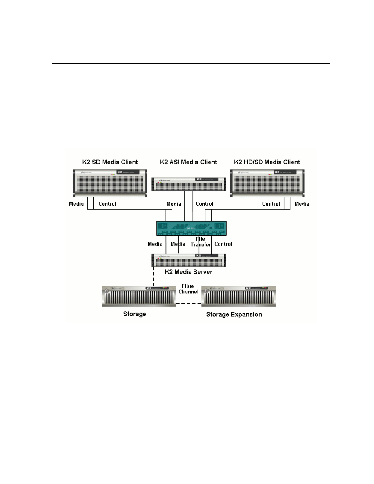
The K2 is an MPEG-2 transport stream capture device that uses the K2 SAN for
media storage. It receives a live Multiple Program Transport Stream from an ASI
input and provides advanced record capabilities of this stream (manual or triggered
captures). Material recorded by K2 then manifests as a K2 clip on the SAN.
The K2 comes with the following items:
• A 2-RU rackable device
• An ASI input card, limited to 84 Mb/s
• A dual port Gigabit Ethernet adapter for remote cont rol and iSCSI access to shared
storage
• An RS-422 card for remote control
• A Software Suite, which allows operating captures locally or remotely
The K2 product is further described in the following section:
• “K2 Features” on page 10
June 10, 2008 K2 ASI Media Client User Manual 9
Page 10

Chapter 1 Product Description
K2 Features
This section provides an overview of K2 features.
Grass Vall ey K2 compo nents & features are:
• High performance ASI input scanning
• Real-time program de-multiplexing and analysis
• Support for MPEG-2 video with SD or HD contents
• Frame-accurate manual or automated capture capabilities
• Support for in-band (SCTE35) or out-band (GPI) commands
• Interfacing with most popular automation systems through VDCP
• Easy-to-Use Graphical User Interface, based on dynamic video thumbnails
• SNMP Monitoring
10 K2 ASI Media Client User Manual June 10, 2008
Page 11

Chapter 2
Getting Started
Topics in this chapter include:
• “System Prerequisites” on page 12
• “Starting K2 ASI Client” on page 12
• “Exiting the Application” on page 14
• “Restarting remotely the K2 ASI device software” on page 14
• “Shutting Down the System” on page 14
June 10, 2008 K2 ASI Media Client User Manual 11
Page 12

Chapter 2 Getting Started
System Prerequisites
Before operating the K2, it must be cabled and configur ed to access shared stor age on
a K2 Storage System. Refer to the K2 Instruction Guide for procedures.
The K2 ASI Graphical User Interface (Remo te ASI Video Client appli cation) should
be installed on the Control Point PC. Refer to the K2 Instruction Manual for
procedures.
Starting K2 ASI Client
When the K2 ASI unit starts up, the K2 ASI application software (namely Video
Server and Browser Server) initiates automatically.
To operate K2 ASI actions, open the remote ASI video application (namely Video
Client) locally or from the Control point PC. This application allows connecting to
any K2 ASI device on the network.
Refer to the K 2 Instructio n Manual for installing AS I video appl ication
To prevent unauthorized modifications to the configuration, handling rights are
determined through the use of two profiles:
•Supervisor
• Configurator
Supervisor Rights
Supervisors can use the ASI video client application software for monitoring
purposes. However, they cannot modify the configuration on the K2 ASI client. In
other words, Super visor s cann ot add , scan, modify, re move in puts, output s nor filt er,
change rate nor perform drag & drops. Supervisors can add, modify or remove
elements i n lists. They can also set or reset analysis parameters.
To set Supervisor right s (default profile) , select
Mode definition dialog is displayed. Select Supervisor and click OK to validate. No
password is necessary for the Supervisor mode.
Configurator Rights
Configurators can do anything: they have all rights.
To set Configurator rights, select
Configurator, enter the password and va lidate.
By default, password is "k2admin". To change it, select
menu. Enter the current password. Then, enter a new password and click
validate.
User mode from the Server menu. The
User mode from the Server menu. Then, select
Password from the Options
OK to
If the current password is erroneous, an error message is displayed. The new password
is set when the current password is correct and the dialog has been validated.
12 K2 ASI Media Client User Manual June 10, 2008
Page 13
K2 ASI Client Connection/Disconnection
K2 ASI Client Connection/Disconnection
Each remote ASI vi deo a pplic ation can be con necte d to one K2 ASI devic e at a t ime.
However, several remote ASI video applications can connect to the same K2 ASI
device.
Manual Connection
Remote ASI video application can run locally on the K2 ASI unit, or remotely from
the Control P oint PC.
So as to connect the remote ASI video application to a K2 ASI device, select the
Server | Local menu or click the toolbar button.
To connect to a remote K2 ASI unit, sel ect the
toolbar button. Then select the name of the K2 ASI device or enter its IP address.
Select the name from th e list or ente r it from the ke yboard. The K2 ASI devi ce list can
be updated by clicking the (browse) button.
Once you have chosen a K2 ASI Client unit, click
Automatic Connection
If the Automatic connection to last K2 ASI dev ice is enabled in the Options |
Preferences
connects to the K2 ASI unitit was last connected to.
For more details on the remote ASI video application user preferences, refer to the
“Client Preferences” section.
menu, when starting up, the remote ASI vi deo appli cation aut omatic ally
Disconnecting from K2 ASI Client
To disconnect from K2 ASI device, sel ect Server | Disconnect menu or click the
toolbar button. The remote ASI video application will no longer be connected.
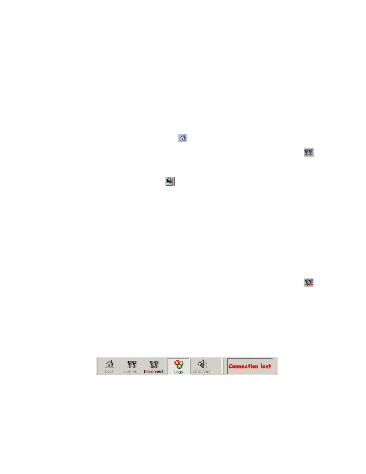
Loss of Connection
Whenever a network problem occurs or the link to the K2 ASI device is interrupted,
the client detects the loss of connection and signals it through an alarm beep. The
remote ASI applicati on icon begins t o flash, and a fl ashing "Connection lost" message
appears in the toolbar.
Server Connect menu or click the
OK to validate.
Most menus are conse quently disabled. The ASI video application auto matically tri es
to reconnect. When the connec tion is (automatically) recove red, the "Connection lost"
message disappears and al l fl ashing stop. T he ASI video appli catio n disc onnects an d
automatically reconnects to the K2 ASI device.
June 10, 2008 K2 ASI Media Client User Manual 13
Page 14

Chapter 2 Getting Started
Exiting the Application
To exit the application, simply close the ASI video application. Select Exit from the
Server menu.
If the
Save windows position and size option is set on the client (ref er to the “Client
Preferences” section) , the position and size of windows will be the same the next t ime
the application is started.
NOTE: Do not stop the Video Server or Browser Server applications on the K2 ASI
device, except for reinstallation purpose.
Restarting remotely the K2 ASI device software
From the remote ASI video application, you can restart the K2 ASI device software
by clicking the
Shutting Down the System
You do not need to exit the applications before shutting down the server.
Select
Server | Restart server menu item.
Shut Down from the Windows 2003 Server Start menu.
14 K2 ASI Media Client User Manual June 10, 2008
Page 15

Chapter 3
Graphical User Interface Overview
Topics in this section include:
• “Information Structure” on page 16
• “Toolbars” on page 17
• “Menu Bar” on page 18
• “Status Bar” on page 19
• “Contextual Menus” on page 20
• “Symbols & Icons” on page 22
• “Drag & Drop Facilities” on page 23
• “Client Preferences” on page 24
• “About Box” on page 25
June 10, 2008 K2 ASI Media Client User Manual 15
Page 16
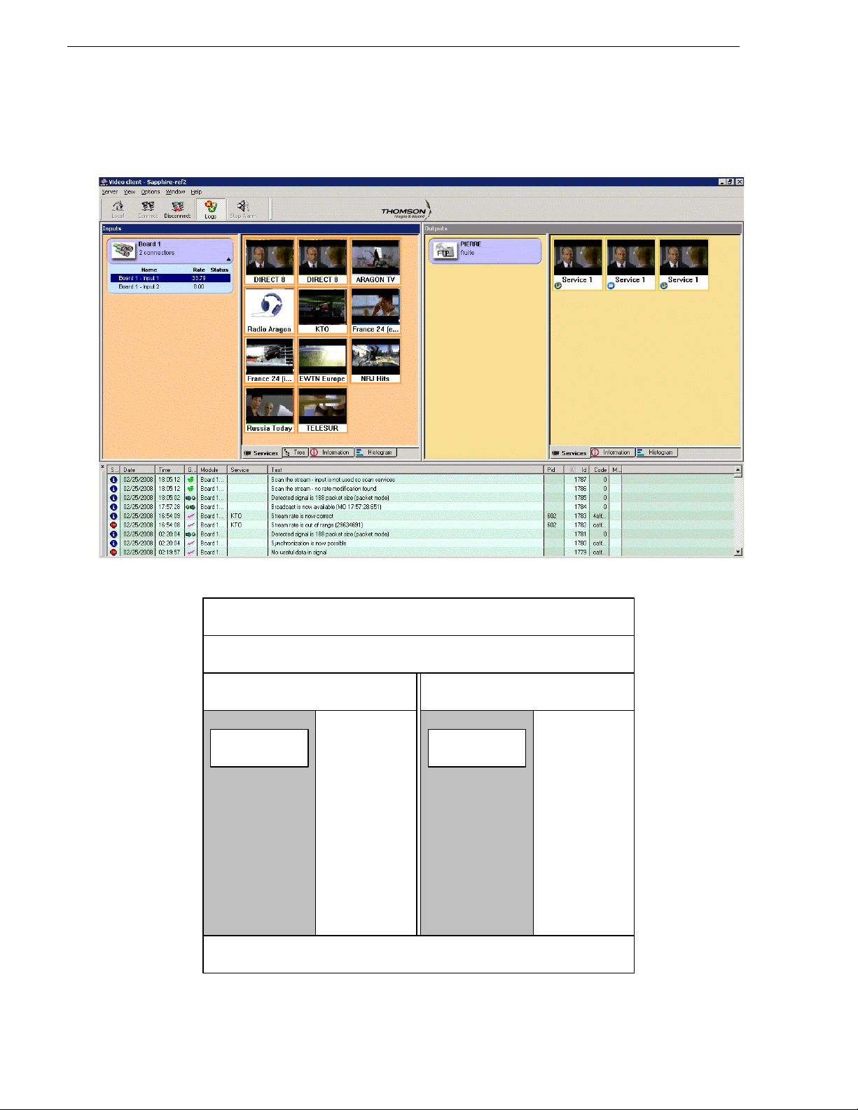
Chapter 3 Graphical User Interface Overview
Menu
Tool Bar
Inputs View Outputs View
Tabular
view
(service,
information,
tree,
histogram)
Tabular
view
(service,
information,
tree,
histogram)
Logs view
ASI board and
connectors
K2
Information Structure
16 K2 ASI Media Client User Manual June 10, 2008
Page 17
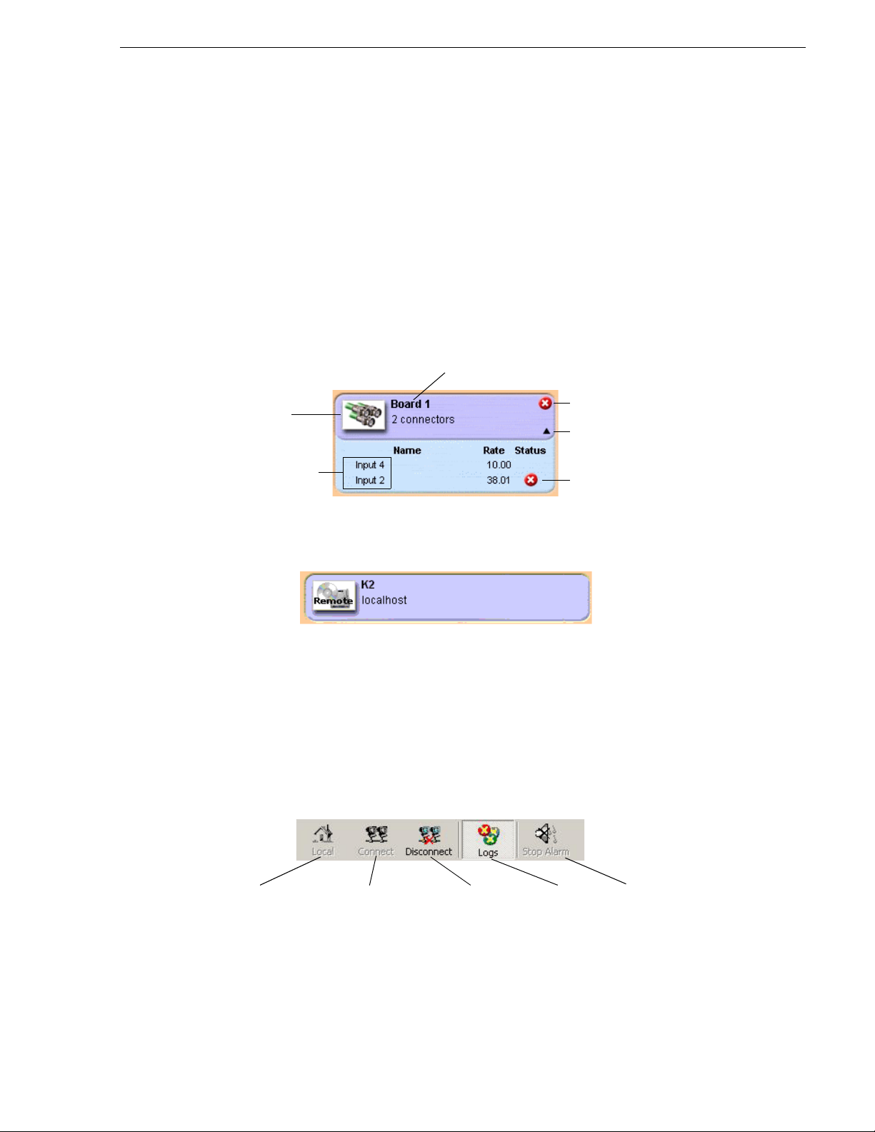
The Graphical User Interface is divided into thre e main views:
Board name
Board error
Toggle button
Input error state
Board type: ASI
Input ASI connectors
Connect the
client to the local
server
Connect the
client to the
remote server
Disconnect the
client from the
server
Open the
Logs view
Reset the
alarm
Inputs panel
•The
•The
•The
The
Inputs view
Outputs view
Logs view
Inputs and Outputs views are both divided into two parts.
The information displayed in the second part (right side of the splitter) depends on
what is currently selected in the left part and on which tab is selected.
Inputs panel
Outputs panel
June 10, 2008 K2 ASI Media Client User Manual 17
Toolbars
The ASI video application features two toolbars:
• the main toolbar
• the connection status toolbar
Main Toolbar
The toolbar display may vary a ccording to the displa y mode defined through the
| Toolbar
menu command.
View
Page 18
Chapter 3 Graphical User Interface Overview
Connection Status Toolbar
This toolbar, located on the bottom of the window, is used to inform you when the
connection to the server has been lost. This toolbar cannot be hidden. When the
connection is OK, nothing is displayed.
Menu Bar
The menu bar content may vary depending on whether you are connected to the K2
ASI device or not. Menus presented below are available when the connection to the
K2 ASI device is effective.
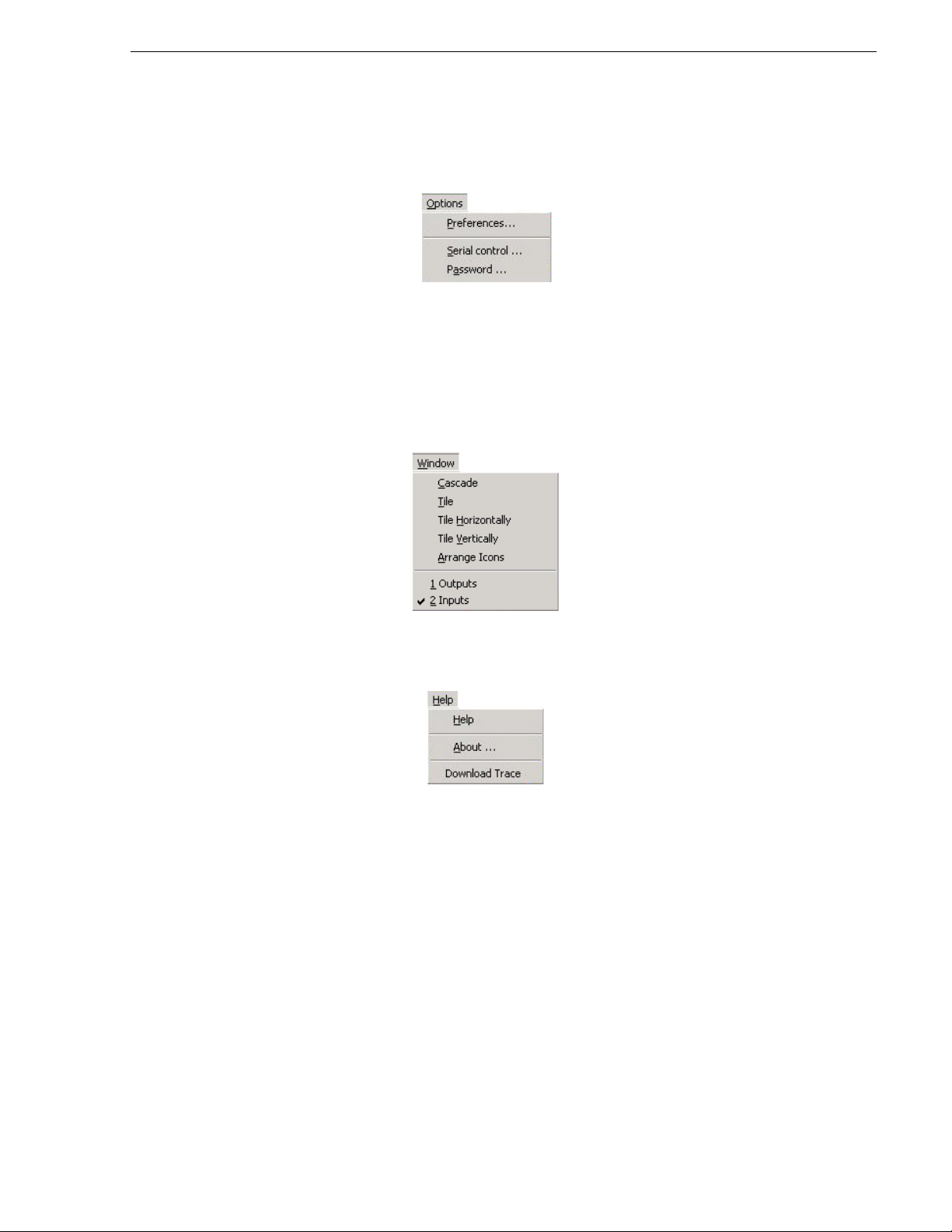
Server Menu
• Disconnect: Disconnecting from the K2 ASI device
• Exit: Exiting the ASI video application
• Restart Server: Restarting the K2 ASI device
• User mode: Defining a User profile (e.g. connecting as Configurator or as
Supervisor)
View Menu
The View men u let s you show or h ide the stat us bar a t th e bott om of the c lient scr een,
define the toolbar aspect or hide it, and show or hide the
Logs view.
18 K2 ASI Media Client User Manual June 10, 2008
Page 19
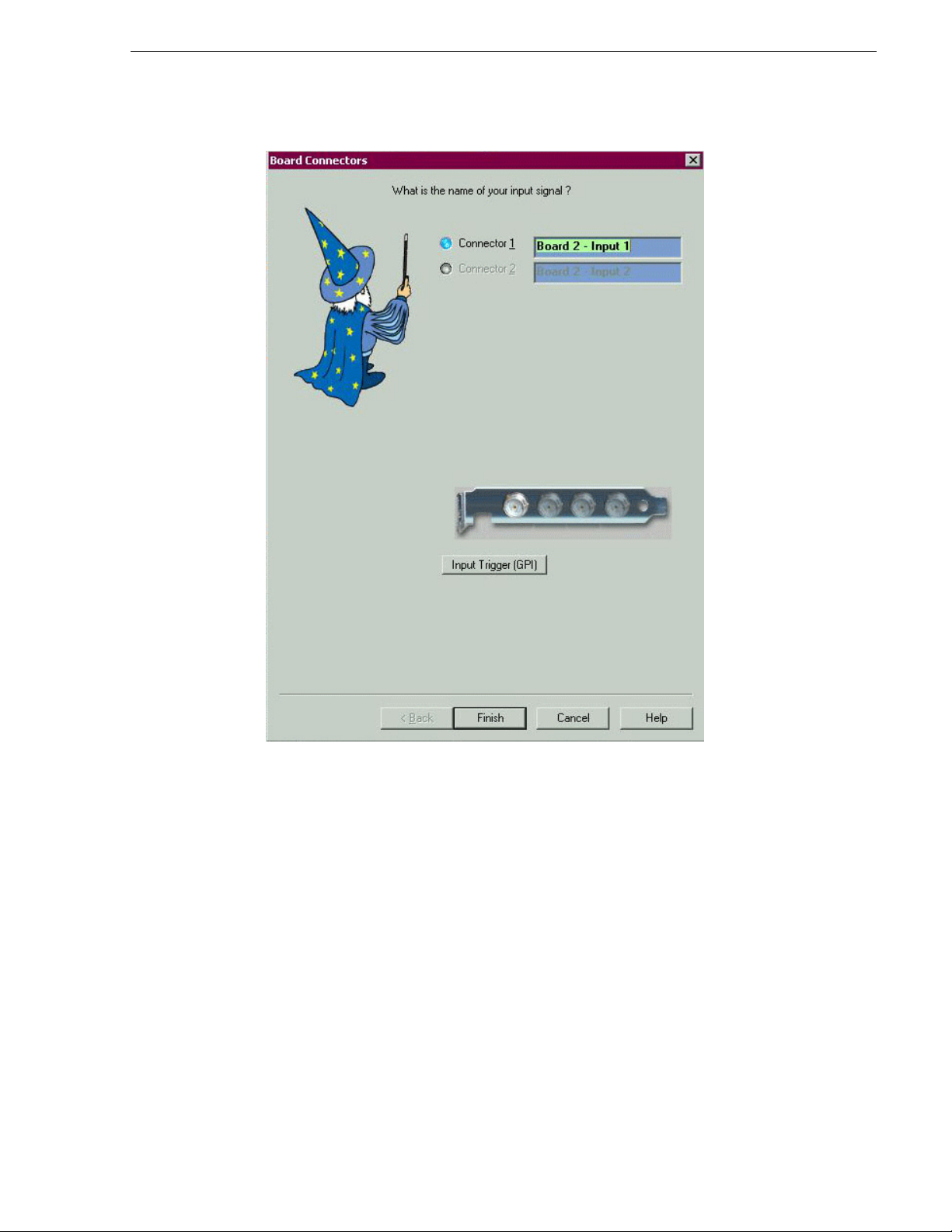
Option Menu
• Preferences: Setting the client preferences
• Serial control: Configuring the serial port to use with an automation system
• Password: Changing the current password to logon in Configurator mode
Window Menu
Option Menu
Help Menu
• Help: Reaching the User Manual in PDF format
• About: Displaying the
• Download Trace: Getting the Trace file from the server
Status Bar
The status bar is divided into three fields:
• The first field cont ains a description of selected menus and buttons
• The second and third fields contain the client date and time when the client is not
connected to a serve r, and the serve r date a nd time when the clien t is con nected to
a server
NOTE: It is recommended that the Control Point PC running the remote ASI video
application has the same date and time than the K2 ASI Media Client device.
About box offering contact, rights & versions information
June 10, 2008 K2 ASI Media Client User Manual 19
Page 20

Chapter 3 Graphical User Interface Overview
To show or hide the status bar, use the View | Status bar menu.
Contextual Menus
Some menu items are common to several menus. They are presented hereafter.
Specific menu items will be presented in their corresponding sections.
• Disable/Enable video decoding: Disabling or enabling video decoding of
thumbnails in the input Services view. This procedure is useful to decrease the
CPU of the K2 ASI Client and when the contro l network has small bandwidt h. It is
recommended to always enable this option
• Current error st ate: When an err or or warning is present on th e input, this menu l ets
you get the current error state
• Acknowledge error: When some errors have disappeared but are have not been
acknowledged yet (i.e. orange st ate) , this menu let s you acknowl edge the m and to
make the overlay disappear from the connector
• Display messages: Opening a window that contains a list of errors and messages
concerning this connector (all services on this connector) in the error list
ASI Input Board Menu
Right-click the ASI board to reach the following contextual menu:
• Add input: Adding input connector. When adding a new input, if the maximum
number of available inputs is reached, a message is displayed. The maximum
number of inputs indic ated in the
Box” section)
• Scan new input: Scanni ng for new inpu ts that are not already lis ted. This proce dure
is useful when a connector with no signal is connected to a stream
Input ASI Connector Menu
Right-click an ASI input to reach the following contextual menu:
Rights panel of the About box (refer to the “About
20 K2 ASI Media Client User Manual June 10, 2008
Page 21

Access Restriction to Menus
• Modify: Modifying the current input (i.e. name, rate, filtering, services on
connector)
• Scan: Scanning the current input to detect new services or remove services that
have disappeared from the i nput st ream. This featu re is disab led when at least one
input service is used by an output
• Remove: Removing the selected input or output
Access Restriction to Menus
Grayed Menus when Connection is Lost
The following menus are not available and are grayed when the connection is lost:
•Add
• Modify
•Remove
•Scan
• Scan new input
• Disable/Enable video decoding
• Current error state
• Acknowledge errors
• Display messages
Grayed Menus for Supervisor Rights
The following menus are not available and grayed when you are a supervisor:
•Add
• Modify
•Remove
•Scan
June 10, 2008 K2 ASI Media Client User Manual 21
Page 22

Chapter 3 Graphical User Interface Overview
• Scan new input
Symbols & Icons
Symbols, overlays and icons are used throughout the Graphical User Interface to
provide at-a-glance health check of services and actions.
Symbols used in the
Symbol Meaning
A red cross overlay is added to a gra phical item whe n an alarm is activ e on this
item or one of its sub-it e ms.
A red cross overlay is added to services when an alarm is active.
An orange cross overlay is added to a graphical item when an alarm has been
activated on this item or one of its sub-items. No alarm is active anymore but
alarm acknowledgment has to be performed.
An orange cross overlay is added to services when an alarm has been activated.
No alarm is active anymore but alarm ac knowledgment has to be performed.
A red ring overlay is added to services when a record action is in progress.
Symbol added to ou tp ut s e rvi ce s th at ar e s c he du le d th r o ug h a r ecord list. If an
event within the record list is on-air, the n ame of this event is displayed near the
symbol. Click it to open the corresponding record list.
Symbol added to the output services th at are managed by a manual record
action. Click it to open the corresponding manual record view.
Symbol added to indicate that the service is scrambled.
Input and Output services views are:
Symbols used in record lists are:
Symbol Meaning
The Start at starting mode is represented by a clock icon.
It is used for an event that shall begin at a given time, whatever event was
recording before it. These starting mode events are made prominent to define
key times in lists (e.g. live events beginning on time). If an event is already
being recorded, it is stopped for the start at event to begin.
The SCTE 35 starting mode is represented by a flag icon.
The GPI starting mode is r epresented by a rising edge icon.
The Manual starting mode is represented by a hand icon.
Record icon: event present in record list. The event is the one that is defined
(and recorded) in a record list.
22 K2 ASI Media Client User Manual June 10, 2008
Page 23

Drag & Drop Facilities
The K2 ASI video application implements the drag and drop facility. It can be used
from a live input (service or group of services or input itself) to an output drive in
order to perform one of the following actions:
• Manual record
• Record list
• Automation control
Drag & Drop Facilities
June 10, 2008 K2 ASI Media Client User Manual 23
Page 24

Chapter 3 Graphical User Interface Overview
Client Preferences
To reach the Client Preferences dialog, go to the Opti ons | Prefere nce s menu. Each
client can have its own preferences, which will not necessarily be the same on other
clients.
• Enable window resizi ng: this opti on enables the res izing of th e
views
• Save windows Position and size: if enabled, any modification to the size and
position of lists, Inputs/Outputs and application windows are kept as well as the
modified position for manual views. When a new client session is opened, the
positions and sizes are rest ore d
• Automatic Connection to last server: if enabled and when the ASI video
application is launched, the application connects to the same K2 ASI device as it
last was last connected to
• Enable Alarm: if one of t hese o ptions is s et, t he al arm ri ngs each t ime a new er ror,
warning or information appears in the message log list. Default alarm is a beep,
however, a sound file can be select ed instead ( provided cli ent machine is equipped
with a sound card). Default Wav file field indicates the name of this wav file.
Alarm sounds until it is acknowledged. It is recommended not to enable alarms
• Confirm acknowledgment of errors: Error s that are no long er present (or ange color
on the services and connectors) can be acknowledged through a right-click on
services or connecto rs. When thi s contextu al menu has b een used, a l ist of cu rrent
errors on services can be displayed or not, depending on the selected option
• Data format in lists: Date format can be chosen: the day can be set as a short name
(first two letter s for each day of the wee k) or a comple te name; month and day c an
appear in the list dates. Date (month/day) can be added to the day column in lists
Inputs and Outputs
• Display msec in lists: if enabled, all time values are displayed in milliseconds
24 K2 ASI Media Client User Manual June 10, 2008
Page 25

About Box
To reach the About box, go to the Help | About menu.
The About box contains three panels:
About Box
•The
•The
•The
Contacts panel provides informa tion on how to contact Thomson Grass Vall ey
technical support
Versions panel contains all software versions and DLL versions used on the
K2 ASI software suite
Rights panel indicates the limitations on the use of the K2 ASI Client, which
depends on the content of the K2 ASI Client options purchased and software
limitations
June 10, 2008 K2 ASI Media Client User Manual 25
Page 26

Chapter 3 Graphical User Interface Overview
26 K2 ASI Media Client User Manual June 10, 2008
Page 27

Chapter 4
Inputs Management
This chapter includes the following topics:
• “Input Scanning” on page 28
• “Adding/Modifying an ASI Input Connector” on page 29
• “Removing Inputs” on page 30
• “Monitoring the Incoming Programs” on page 31
June 10, 2008 K2 ASI Media Client User Manual 27
Page 28

Chapter 4 Inputs Management
Input Scanning
The first thing to do b efore using the K2 i s to plu g the ASI input s int o the connect ors
and to add the services. If the input has MPEG 2 PSI/SI/PSIP tables, the video server
detects and adds the ser vices au tomati cally . This process is known as inpu t scanni ng.
All the new inputs can be scanned together - which is the case when the server is
started up for the first time - or indepen dently.
Scanning a New Input
The Scan new input feature is used to scan all inputs that are not already created and
to add inputs with a strea m pre sent on th em. Servi ces for new inpu ts are add ed to t he
Services view.
To scan a new input:
1. Right-click an input board (not the input itself, but its board).
2. Select
3. A confirmation is required. Click
4. Any new connector with a valid signal is added (default names are Input x).
Scan New Input.
Already existing inputs are not affected nor scanned.
Scanning an Existing ASI Input
The Scan input feature is used on the input connector. It scans the input stream to
determine (using its tables) the content of the stream and then modifies the services
and rate to take account of new content.
NOTE: An i nput cannot be scanned whi le in use (i.e. when used for manual record or
record event).
To scan an existing ASI input:
1. Right-click an ASI input.
2. Select
3. If an existing input is scanned and i ts services a re found to have ch anged, they will
The rate will be updated if it is found to be different from the signal rate.
Scan.
be modified (new ser vices will be add ed and services tha t do not exist a nymore will
be removed).
OK to validate.
Adding a New ASI Input & Scanning its Content
To add a new ASI input and scan its content (without scanning other inputs):
1. Right-click the ASI board and select
The
Board Connectors dialog opens.
28 K2 ASI Media Client User Manual June 10, 2008
Add Input.
Page 29
Adding/Modifying an ASI Input Connector
2. Select the relevant input.
3. Click
The new input is automatically added to the ASI board.
Finish.
Adding/Modifying an ASI Input Connector
NOTE: If you do not have Configurator rights or if the connection is lost, the menu
is unavailable.
To add a new input:
1. Right-click the ASI board and select
2. If at least one connector is available and you have Configurator rights, a dialog
opens.
NOTE: If all inputs have already been created, a message is displayed. It is not
possible to add a connector.
June 10, 2008 K2 ASI Media Client User Manual 29
Add input.
Page 30

Chapter 4 Inputs Management
One trigger per board is available, only on connector 1.
3. Select the connector to be added.
Connectors that are already created cannot be selected and are grayed. Default
connector name is "I nput x", wh ere x is the connec tor’s numb er. This n ame can be
changed and will be displayed in the connector view, under the connector image.
Underneath the list of connectors, there is a representation of the physical
connectors on the ASI board. When a connector is selected in the top list of
connectors, the one on the picture is lit up.
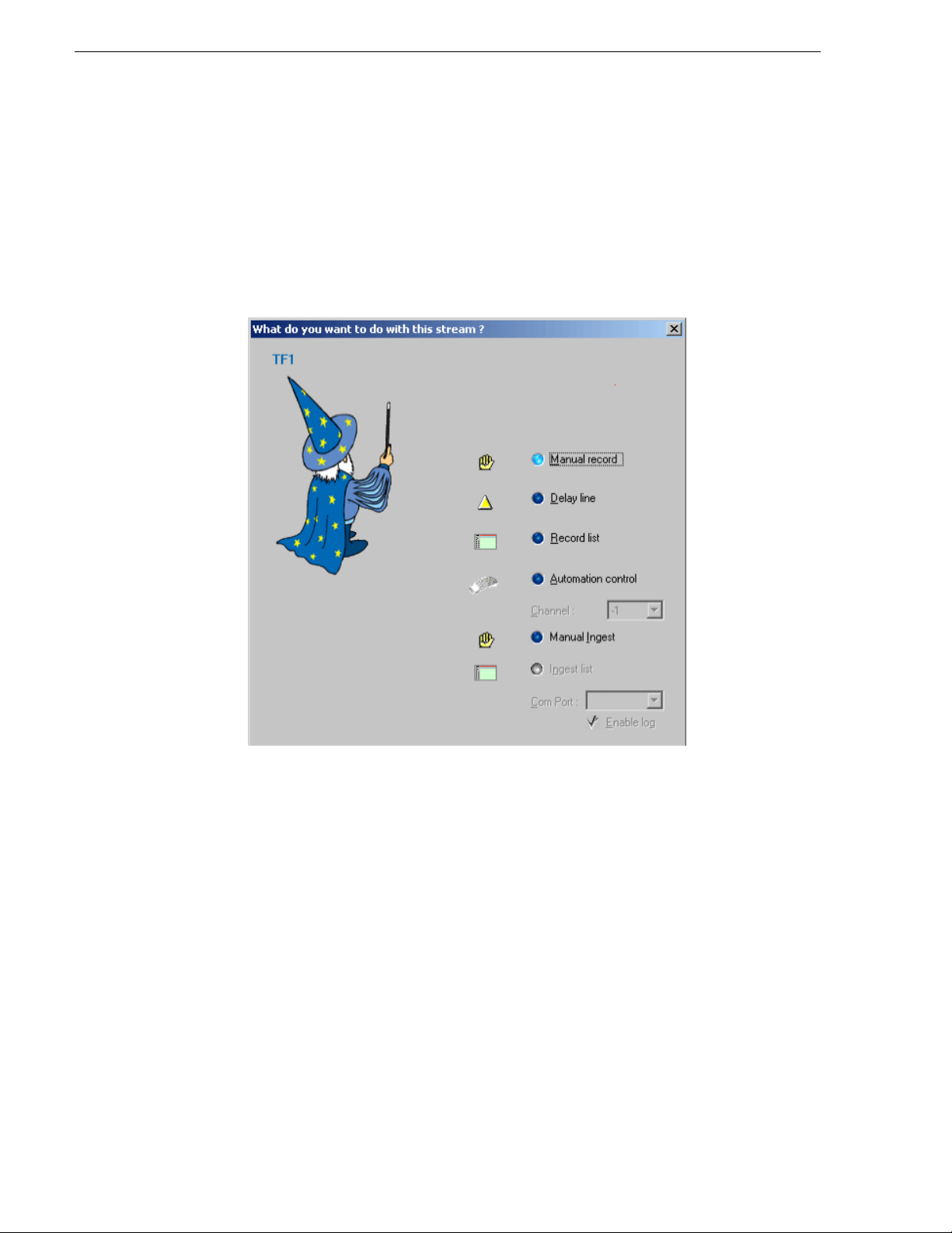
4. GPI events can be managed by the input. Click the
Input Trigger (GPI) button to
display the parameters,
Three kinds of input events are managed:
• None: no GPI event is managed (default parameter) ,
• Rising: rising edge events are managed,
• Falling: falling edge events are managed.
These events may be used to trigger record actions.
Events can be logged in the
Logs view if the Enable log trigger option is enabled.
Before validating the addition, plug in the input on the given connector to make
sure the signal is detected.
5. Click
Finish to add the input connector and scan its services.
If no signal is pre sent, the
Scan Input option (in the connector contextual menu) wil l
have to be used when the signal is plugged in. This view can be accessed when
using the connector contextual menu or the
Modify feature from the service
contextual menu. The connector cannot be changed but its name can be set.
Removing Inputs
To remove an input:
1. Select the input you wish to remove from the
2. Right-click it and select
3. A confirmation is requested: click
Remove.
Yes.
4. If the input is currently used by an output or a record, a message is displayed to
indicate that the input cannot be deleted.
5. If the input you wish to remove is not cur rently used by a record or an ou tput, click
OK to validate.
The input content is removed.
30 K2 ASI Media Client User Manual June 10, 2008
Inputs view.
Page 31

Monitoring the Incoming Programs
Monitoring the Incoming Programs
Once an input has bee n scanned, its cont ent is added to the Services view. This sect ion
contains a full description of the monitoring views.
Services View
To reach the Services view, first select an input or output item (i.e. board or
connector) and then click the
selected item type.
The video clien t application perf or ms the global supervision of all inc oming streams
and all output streams. It displays the logo channel or the decoded picture for each
service and indicates the program status.
By default, the video is decoded by sampling (refresh period depends on t he number
of services that are managed by the server) when the video service is not scrambled.
The other services are represented by a specific logo.
You can change the specific logos by selecting a bitmap file corresponding to the
channel logo. Bitmap files are stored on the video server.
Services tab. The displayed conte nt depends on the
Logo Service type
Services Menu
The
Services menu is the same for the Inputs and Outputs panels.
To reach the
Audio services
Data services
Video services
Services menu, right-click on a service from the Services view.
June 10, 2008 K2 ASI Media Client User Manual 31
Page 32

Chapter 4 Inputs Management
Menu item Function
Settings/Modify For current service, remapping this service PID configuration and
Analysis Reaching analysis settings for current service.
Logo Selecting the service logo to replace default picture.
No Logo Deleting service logo and replacing it with default service (i.e. TV, d ata
Current error state Wh en a n erro r or warn ing is pres ent on t he servic e, th is menu lets yo u
Acknowledge Errors When some er rors have disappeared but are have not been
Display Messages Opening a window that contai ns a list of errors and messages
Grayed Menus when Connection is Lost
changing the name and program number of output service.
or radio). This item is grayed if no logo is present on the service.
get the current error state.
acknowledged yet (i. e. orange state), thi s menu lets you acknowledge
them and make the overlay disappear from the service.
concerning this service in the error list.
The following menus are not available and are grayed when the connection is lost:
• Modify input
• Scan input
• Settings/Modify
•Analysis
•Logo
• No logo
Grayed Menus for Supervisor Rights
The following menus are not available and are grayed when you are a supervisor:
• Modify input
• Scan input
• Settings/Modify (can be reached but in read-only mode)
32 K2 ASI Media Client User Manual June 10, 2008
Page 33

Input Services View
Services View
The input
Services view provides an immediate "health check" of input services
through the display of overlays. For further details, see the “Symbols & Icons”
section.
Output Services View
Services view is the same for the Inputs and Outputs panels. Refer to the “Input
The
Services View”section.
In case of synchronizati on loss, no data or no signal i s detected over the inp ut, and the
Services view is cleared. The cause for this can be:
• No signal: the server does not detect any signal on the input. The wire is
disconnected or signal is no longer present
• No data: the stream only contains empty packets. No more useful data is present
• No synchro: no synchronization byte (0x47) detected at the beginning of each
packet (every 188 or 204 bytes)
June 10, 2008 K2 ASI Media Client User Manual 33
Page 34

Chapter 4 Inputs Management
Tree View
This view gives all MPEG-2-DVB or ATSC parameters for the incoming stream or
output stream.
Tree View Availability
The
Tree view is available for each ASI input.
Reaching the Tree View
To reach the
Tree view, select an input and then click the Tree tab.
Information View
ASI Board Information View
To reach th e ASI board
Information tab.
The ASI board
Information view displays the connector. When used, its name is
displayed. When unused, the "Not used" label is displayed.
34 K2 ASI Media Client User Manual June 10, 2008
Information view, select the ASI board and click the
Page 35

Connector Information View
Information View
To reach this view, select a connector and click the
Information tab.
This view gives inf ormati on on t he selec ted bo ard, c onnect or or servi ce. I nfo rmation
provided vary according to the element type you have selected.
The first item provides an information summary on the connector:
• card number
• connector number
• input/output rate
• demux rate
• filtered PID
The second item provides information on actions on the input. Sub item is:
• Recording: lists the record list with the number of events and the manual record
with free space, filename, length and status if recording
June 10, 2008 K2 ASI Media Client User Manual 35
Page 36

Chapter 4 Inputs Management
Histogram View
The Histogram view gives the current rate for each service of the selected input/
output. The current rate is ind icated to the lef t of the histogram. The maxi mum rate is
indicated to the right of the histogram. The maximum rate of a ser vice is the maximum
rate of the s ervice s ince the vide o server was star ted and the ser vice found (compu ted
rate).
Histogram view is available for t he following items:
The
• ASI input
• Record action (manual record or record list)
To reach the
Histogram view, select one item, then click the Histogram tab
Performing Ana lyses
A number of analyses c an be performed for each incoming s tream and output services
independently. Analysis results are logged to the
If an analys is error is raised on a service, an overlay is displayed over th e decoded
picture or logo. See the “Symbol s & Icons” section for further details on the symbols
and color codes used.
Analysis label Detail
Table coherence Consistency in the MPEG-2, DVB or ATSC tables (e.g. PMT
PID presence Presence of listed PIDs is checked. If one PID is not detected during
Video decoding When enabled, video is decoded periodically provided the service is
Logs view.
declared in PAT but not present) . Thi s analysis is performed on a
stream (i.e. for all the services of the stream). If this parameter is
modified for one service, the modification is applied to all other
services in the stream.
1 second, an alarm is set.
not scrambled. The refresh period depends on the number of services
that are managed by the video server.
Picture freeze If a picture does not vary (i.e. is frozen) for more than a user-defined
duration, an alarm is set. This parameter is only available if video
decoding is set. If a null value is set, no test is performed.
MPEG transport flags Presence of MPEG transport flag is checked in the stream. These
flags are TEI (Transport Error Indicator), CC (Continuity Counter)
and DI (Discontinuity Indicator).
Service rate If the sum of the component rates differs too greatly from the
analysis rate (i.e. tolerance to given bit/s), an alarm is set.
Transport stream rate If the rate computed from the PCR differs too much from the analysis
rate (i.e. tolerance to 100 Kbit/ s), an alarm is set. This analysis is only
performed if the Table Coherence is checked. This parameter is the
same for all services of a single stream.
Each analysis can be enabled or disabled. By default, all analyses are performed,
except the Service rate analysis and the Picture freeze analysis.
36 K2 ASI Media Client User Manual June 10, 2008
Page 37

Performing Analyses
Analysis parameters can be set for each service by opening the corresponding
contextual menu: right-click the service thumbnail and select
Analysis.
• Wave file: default sound played for an alarm is the buzzer. You can associate a
particular WAV file to each service
• Disable analysis: you can disable the analysis for different time slots
• PID to check: only PIDs checked in this list will be used in the analysis. By default,
all the PIDs of the service are checked
June 10, 2008 K2 ASI Media Client User Manual 37
Page 38

Chapter 4 Inputs Management
38 K2 ASI Media Client User Manual June 10, 2008
Page 39

Chapter 5
Recording
This chapter includes the following topics:
• “Performing a Manual Record” on page 40
• “Creating a Record List” on page 42
• “Record List Views” on page 44
• “Inserting an Event into a Record List” on page 47
• “Modifying an Event” on page 48
• “Deleting an Event from the List” on page 48
• “Stopping an Event” on page 48
• “Recording an Event Immediately” on page 48
• “Saving/Printing a List” on page 48
• “Loading a List” on page 48
• “Defining an Event” on page49
June 10, 2008 K2 ASI Media Client User Manual 39
Page 40
Chapter 5 Recording
Performing a Manual Record
K2 allows crash-recording any of the programs available in input.
To create the record action:
1. Drag a program from the ASI input area and drop it in the K2 ASI output drive.
2. Define the output action in the displayed dialog. Select
Manual record.
3. Click
40 K2 ASI Media Client User Manual June 10, 2008
Next to continue.
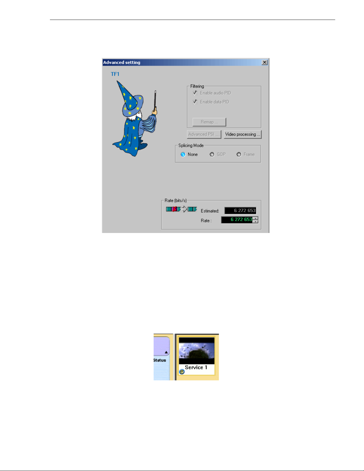
The
Advanced Settings dialog opens.
Page 41
Performing a Manual Record
NOTE: The Enable audio PID option is ena bled if at least one audio PID is selecte d.
The Enable data PID option is enabled if at least one data PID is selected.
To view the selected PIDs, click Remap.
An estimate d total rate for the selecte d services is displayed. This rate is actu ally
the sum of the maximum rate of each service at the time of output creation. The
maximum rate of each service is calculat ed by the video server. An off set is add ed
to prevent overflow.
4. Define the recording rate and click
Finish.
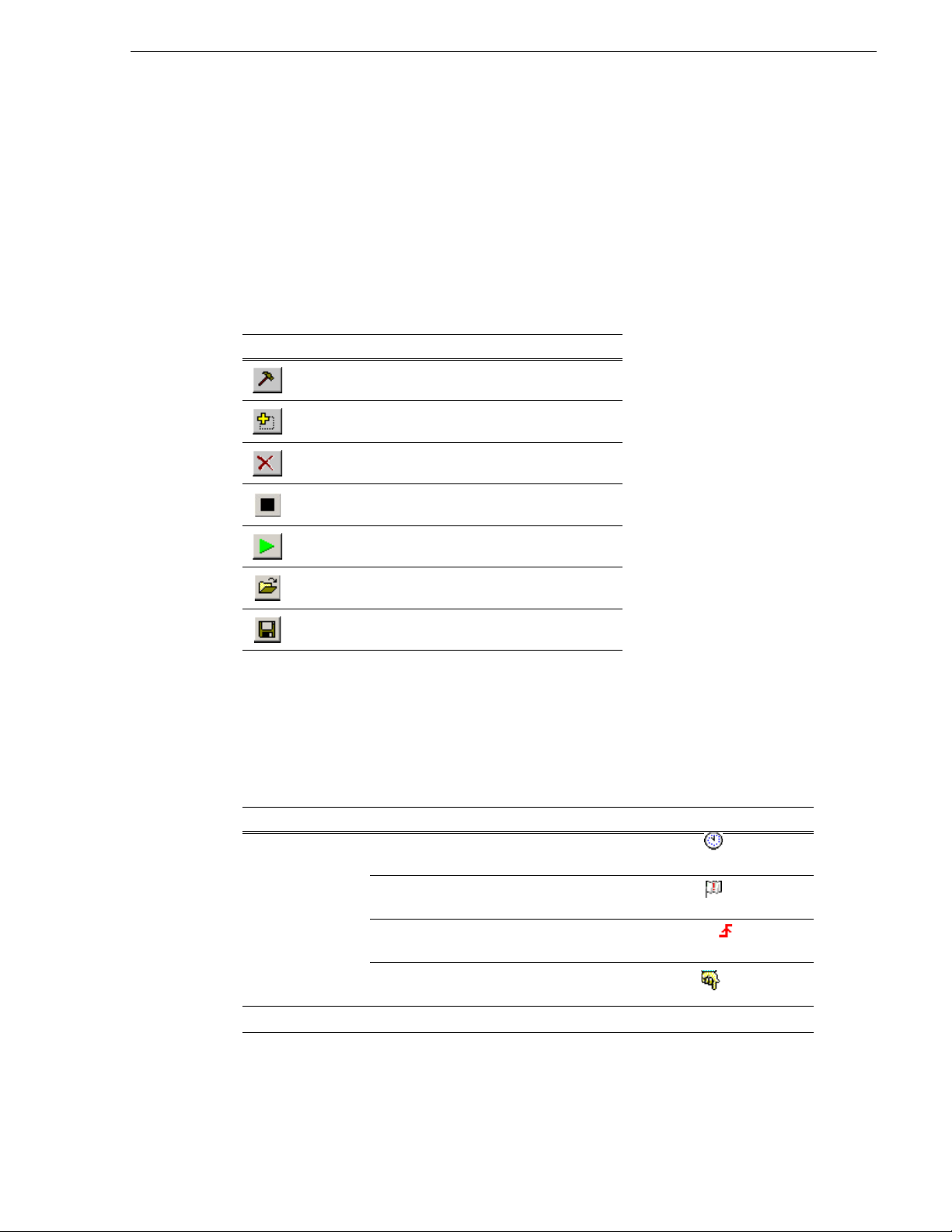
The Manual record is crea te d and an it em is added under the sel ected output dr iv e.
Recorded services are displayed in the outpu t
Services view. An overla y indicating
manual recording is added to the bottom left corner of the servic e.
If several services have been selected, each service is displayed in the
Services
view. In this case, of course, all services are recorded.
June 10, 2008 K2 ASI Media Client User Manual 41
Page 42

Chapter 5 Recording
5. Click the hand icon in the bottom-left corner of the manual record overlay.
The
Manual record dialog opens.
6. Fill in the
Directory, Filename and Duration fields; then the free space on disk is
indicated in the following format: day, hour, minute, seconds.
When you are done with your settings, click the button to start recording.
While recording, the thumbnail (provided it is not scrambled) is continually
updated. A progress bar is displayed.
It provides information on the current position in the file.
Creating a Record List
To create a record list:
1. Drag a program from the ASI input area and drop it in the K2 ASI output drive.
A dialog opens.
2. To create the record list, select
Record list and click Next.
The
Advanced Setting dialog is displayed.
3. Set the record rate and click
42 K2 ASI Media Client User Manual June 10, 2008
Next.
Page 43

The Setup the record list parameters dialog is displayed.
Requested start
time for recording
T = 0
T = -1
Input delay
Creating a Record List
4. Set the record list parameters.
The drive is set and cannot be modified. It is the drive onto which the selected
services have been dropped for the record. The directory, however, can be
modified. Click the
button and select a directory on the current drive.
• Select the Dated mode: events are deleted from the record list once they have
been recorded.
• Input delay parameter: used to start a re cording actio n earlier than the requested
start time. The
Input delay option lets you anticipate the recording action.
5. The record list is created and the corresponding item is added under the selected
output drive.
The recorded services are displayed in the output
Services view. An overlay
indicating that service is in the record list is added to the bottom left corner of the
service.
June 10, 2008 K2 ASI Media Client User Manual 43
Page 44

Chapter 5 Recording
6. Click the record list icon in the bottom-left corner of the overlay.
The
Record List view is displayed. It is empty.
The name of the selected service c orresponds t o the tit le of the
our example, the service name is Service 1 and so is the record list's. When several
services are selected, the title is MPTS.
The top two lines describe the current recording event (red line), when present, and
the next event to be recorded (orange line). The record list is displayed in
minimized mode.
Use the toggle buttons to maximize it vertically and horizontally.
NOTE: The t humbnail i s the o ne cor responding to t he sele cted ser vice th at is used t o
display the list.
Record List Views
Reaching the Lists
To reach the Lists view, there must be at least one record list created.
Weekly record list means that th e e vent i s defined not only for this week but al so for
all the subseque nt we eks. Event will be recorded this week; the week after, it wil l be
destroyed to be recorded again.
To reach the
on the record list in the ASI board s and connectors out put view. If the view is alr eady
open, it pops to the front of the screen.
Lists view, click the button located under the services or doubl e-click
Record list view. In
The top two lines des cribe the ev ent that is c urrentl y being recor ded (red line ) and the
next event to be recorded (orange line). The status of each even t is indicat ed to the left
of each line. Each line has a decreasing counter indicating the time left for the event
to record (red line) or the time remaining before it begins (orange line) when no event
is recording.
44 K2 ASI Media Client User Manual June 10, 2008
Page 45
Customizing List Display
The size and position of the lists can be modified and saved if the corresponding
Options | Preferences options are selected. The views will then open at the s ame
position each time you reach them. Each column can be dragged and dropped and
resized. All modifications are saved when the view is closed.
Toolbar Buttons & Information Elements
Button Corresponding action
Modifying the selected frag ment.
Inserting a new fragment (record list).
Deleting the selection.
Stopping the current event.
Customizing List Display
List Fields
For further details, see the “Symbols & Icons” section.
Fields in the list are the following:
Field Possible value
Starting mode The Start at starting mode is represen ted by a clock icon ( ) in the first
Starting the selected event.
Loading a list.
Saving the current list.
column.
The SCTE 35 starting mode is represented by a flag icon ( ) in the first
column.
The GPI starting mode is represented by a rising edge icon ( ) in the first
column.
The Manual star ting mode is represented by a hand icon ( ) in the first
column.
Title Event name.
June 10, 2008 K2 ASI Media Client User Manual 45
Page 46

Chapter 5 Recording
Field Possible value
Status RECORDING ERROR: indicates that the on-ai r event cannot be recorded
because of an error. The top line flashes. The reason for this could be that the
file is absent on disks, the live input is corrupted or equipme nt is out of order.
An error is consequently logged in the L ogs view.
RECORDING: indicates that the event is being recorded.
RECORDED: the event is present on the di sks.
NOT PRESENT: the event is not yet present on t he di sks (not recorded).
NOT DEFINED: transitory state after the record during which the event is
mounted. It is followed either by a RECORDER or a NOT DEFINED state.
Duration, Day,
Begin, End
Name Name of the event (freely definable - informal field only).
Type Reco rd ( icon): present in a record list.
These fields define the beginning, the duration and the end time of the event.
46 K2 ASI Media Client User Manual June 10, 2008
Page 47

Inserting an Event into a Record List
Inserting an Event into a Record List
NOTE: A record l ist can be loade d from a file . The ev ents ar e added . The record list
can also be saved to a fi le.
To insert an event into the record list:
1. Select the output
Services view.
2. Click the record list overlay on the thumbnail.
The
Record list view opens.
Let us suppose that you wish to insert an event called "Dancing" on Thursday, at
11:30, for a 10-minute duration. The current list already has two events. The first
event is named "what's on". It starts on Thu rsday at 11:00 AM and la sts 15 minutes.
The second event is named "spo rt TV" . It s tarts a t 12: 00 AM an d l asts 1 0 minut es.
• If the list is empty (e.g. if you have just created it), skip this step and go directly
to step 3.
• If the list alread y conta ins at le ast one eve nt, cli ck in the l ist to s elect th e time at
which you wish to insert the "Dancing" event. Event will be inserted after the
selected one. In this case, you have to insert it after the "what's on" event,
because the previous event ends at 11:15 AM and "sport TV" begins at 12:00
AM.
3. Click the toolbar button.
The
Segment setting dialog is displayed.
4. Enter the name, begin time and durati on of t he event . Eithe r use t he arr ow button s
or type the values directly from your keyboard. The
enabled. Click
June 10, 2008 K2 ASI Media Client User Manual 47
OK to validate.
Start at option is already
Page 48

Chapter 5 Recording
You can save record lists to file or load them from file, using the corresponding
toolbar buttons. When l oading a reco rd li st, firs t se lect the time at which yo u want to
insert it, as you did when creating an event (i.e. list will be inserted after selected
event).
Modifying an Event
Select an event and cli ck Modify (you can double- click in the list as wel l): the Segment
Setting
equals to using the
It is not possible to modify the name of the event.
When modifying an event that is currently being recorded, some parameters cannot
be modified.
Deleting an Event from the List
Select one or more eve nts to be deleted and cl ick the Delete button.
This action is not possible if the event is being recorded.
The "Dancin g" event is inserted at 11:30 AM, after the selected event.
dialog opens. If the selected even t is not a va lid event, usi ng the Modify b utton
Insert one.
Stopping an Event
Select the event that is being record ed and click the Stop butt on. The event is stopped
as soon as possible.
Recording an Event Immediately
Select an event in the list and click th e Record button. The event that was currently
being recorded is stopped as soon as pos si ble and the recording of the selected event
is launched.
Saving/Printing a List
Lists can be saved on the client disk . The default ex tension is lis t. The saved fil e must
not be edited (binary format).
Contextual menu gives access to the
Print function to print out lists.
Loading a List
A list can be loaded from the client disk. This list will be inserted into the current list.
To do so, select the in sertion poin t (i.e. the event i n the list) and s elect the file list. The
list is inserted at the insertion point, in append mode.
48 K2 ASI Media Client User Manual June 10, 2008
Page 49

Defining an Event
When inserting, modifying or pasting an Event, the following panels are displayed:
Defining an Event
Starting mode: t o create a star t at (s tart at give n time), d elete at (delet e at gi ven time) ,
manual, GPI (manual trigger) and/or In Band (Cue Tone). Several Start triggers can
be used for t he same event.
Stopping mode: to create a Duration (stop when duration is elapsed), GPI (manual
trigger) and/or In Band (Cue Tone). Several Stop triggers can be used for the same
event.
The begin time shall be set between previous "start at" in the list and next one. The
begin time of the event cannot be selected as a time after the stored file life (i.e. the
beginning of the recor ded even t plus t he "Ke ep fil e during " time se t in the record list
definition).
The duration is the total duration of the event to be recorded. Null duration is allowed
only if it is another stop trigger.
The Start at starting mode shows the begin time. Day of week, hour, minute and
second may be selected.
June 10, 2008 K2 ASI Media Client User Manual 49
Page 50

Chapter 5 Recording
The Delete at starting mode shows the delete time (only with Dated list and GPI or/
and In Band start trigger). Day of week, hour, minute and second may be selected.
GPI: starting or stopping mode that allows, when GPI mode is activated, to trigger the
beginning and/or the end of the event manually.
Input trigger shall be shown:
• Number: number of the input trig ger connector use d. Start and stop GPI ar e totally
• Edge: edge kind (i.e. rising or falling) for a number superior to 5, optional card is
independent (i.e. an event can be associated with a number for its start mode and
another one for its stop mode)
required
In Band: starting or stopping mode that allows, provided the In Band mode is
activated, to trigger the beginning and/or the end of the event through an in-band
signal.
The In Band signal shall be shown:
• Input: choose from t he list the numbe r of the input ASI connec tor tha t contains the
In Band signal
• Service: choose from the list the service name that contains the In Band signal
• Event ID: an event can be associated with any event (event begins/stops when a
Cue Tone event is received) or with a specific event ID (event begins/stops when
the specifi c event ID is re ceived). St art and stop In Band are totally indepe ndent
(an event can be associated wit h a specific even t ID for his start mode and an other
for his stop mode)
Normal/Inverted: there is a specific Cue Tone to start an event and another to stop it.
If Normal is enabled, the event begins when the specific start Cue Tone is received
and stops when the specific stop Cue Tone is received. If Inverted is enab led, the
event begins with the specific stop Cue Tone and stops with the specific start Cue
Tone.
50 K2 ASI Media Client User Manual June 10, 2008
Page 51

Chapter 6
Automation System
This chapter includes the following topics:
• “Connecting the Automation System” on page 52
• “Creating a Record List from the K2 ASI Client” on page 53
• “Configuring a K2 ASI client device from the Automation System” on page 54
June 10, 2008 K2 ASI Media Client User Manual 51
Page 52

Chapter 6 Automation System
Connecting the Automation System
Record lists can be managed using an automation system. The automation system is
connected to the video server through RS 422 serial links. When the automation
system is connected to the video server, the serial port has to be configured on the
video server.
To open the connection with the automation system:
1. Select the
Options | Serial port menu.
The Automation control settings dialog opens.
2. The drop-down list contains the list of all available serial ports. Select the serial
port to be used.
COM1 and COM2 are RS 232 ports. COM3, 4, 5 and 6 are RS 422 ports.
3. Enable the
The
4. Define the parameters in the
5. Click
A message is added to the
Used by automation system option.
Settings and Advanced Settings areas are now avail able.
Settings area to configure the serial port.
OK when you are done with the settings.
Logs view when the serial port is correctly opened
(otherwise, an error message is added).
The word "used" is added at the end of the serial port name in the drop-down list of
serial ports.
52 K2 ASI Media Client User Manual June 10, 2008
Page 53

Creating a Record List from the K2 ASI Client
Creating a Record List from the K2 ASI Client
To create a record list from the K2 ASI client:
1. Drop a service from an input to an output drive.
2. In the displayed dialog, check
Automation control.
3. Select the channel (minus value for recording) you want to use, then click
4. Validate the following dialogs (see the “Cr eating a Record List” section for furth er
details).
The record list is created. It is in read-only mode when editing from the video
client. Events in the record list are managed by commands coming from the
automation system.
NOTE: Channel X is not nece ssarily as sociated with the ser ial port X but is a virtua l
channel number set in the automation system.
June 10, 2008 K2 ASI Media Client User Manual 53
Next.
Page 54

Chapter 6 Automation System
Configuring a K2 ASI client device from the Automation System
From the Automation System, the K2 ASI Media Client should be declared as an
Extended-ID video server.
Its general encoding parameters are:
• Cue Time: 5 seconds
• Disk precall: 1 second.
54 K2 ASI Media Client User Manual June 10, 2008
Page 55

Chapter 7
Message & Error Management
This chapter includes the following topics:
• “Logs View” on page 56
• “Alarms” on page 57
• “Specific Messages view” on page 57
• “Current Error State” on page 57
• “Acknowledging Errors” on page 58
June 10, 2008 K2 ASI Media Client User Manual 55
Page 56

Chapter 7 Message & Error Management
Logs View
The Logs view provides the list of error, warni ng and informatio n messages. You can
show it or hide it via the
NOTE: Messages can be sort ed, filtered and identified in a user-friendl y way. To sort
messages, double-click on the desired column header (e.g. double-click the Time
column header to sort the messages by date).
In this view, the following types of detected alarms are listed:
•System state
View | Logs menu, or by clicking the toolbar button.
• Inconsist ency within the record lists
• Synchronization analysis
• PCR validity
• PID presence
The following contextual menu can be reached from the
Menu item Funct ion
Show all Showing all messages, including masked messages. Mask ed messages
are no longer masked.
Show not masked Showing all messages that are not set as masked.
Mask Masking selected elements in the list.
Logs view:
Mask all Hiding all elements. To show not masked again, use the Show not
masked contextual menu item.
56 K2 ASI Media Client User Manual June 10, 2008
Page 57

Alarms
Each time a new error arises, an alarm can be heard (provided options for this have
been selected, see the “Client Preferences” section). In formation messages are
indicated by blue icons. Error messages are red-colored. Warnings are
orange-colored.
To stop alarms, use the toolbar button. All alarms will stop. Sin ce alar ms are
client dependent, stopping an alarm on one client will not stop it on the others.
Specific Messages view
Messages relative to a particular service or connector can be directly reached to view
the alarms concerning a selected service or connector. To do so, select a connector,
an input or a service, and select
Display Messages from the contextual menu.
All messages are a vailable in a d aily log file th at is lo cated on t he ser ver. File s can be
found in the C:\Report\VideoServer folder.
Current Error State
Alarms
To reach the current error state of an it em ( i.e . boa rd, connector, service), right-click
it and select
Current error state from th e menu.
Error state window is displayed. It lists current errors (in red) and errors to
acknowledge (in orange). Listed errors are the following:
Listed Error Meaning
Opening stream error An input or output card connector cannot be used on the ASI
card or a network destination is unreachable.
Reading stream error Error while reading data.
Writing stream error Error chile writing data.
Initializing stream error Error while initializing input or output on ASI board.
Starting stream err or Error starting board, input or output.
Synchronize error Synchronization error on the stream.
Table coherence erro r The PSI table content is not cor rect.
June 10, 2008 K2 ASI Media Client User Manual 57
Page 58

Chapter 7 Message & Error Management
Listed Error Meaning
Input overflow error System overloaded (CPU, disk access).
Demultiplexer overflow error The demux rate is too low.
Communication error Error while communicating with OpenM ux
PID presence error An expected PID is not present.
Stream rate error The stream rate is incorrect (using PCR - usually due to PCR
Service rate error The service rate is incorrect (by counting service packets).
Discontinuity error Shifting in continuity counter.
Video freeze error The video h as not changed for a long time.
Acknowledging Errors
When an error is raise d, it is automatica lly log ged. However , when it disa ppears, it is
not deleted from the list of errors.
To indicate that an error has occ urred and is no l onger prese nt, the error st ate switches
from red to orange. You should acknowledge it. This can be done for all connector
errors through t he
through the same menu.
Acknowledge error contextual menu or for each service , one by one,
errors).
®
software.
To confirm the acknowledgement, click
OK. Once they have been acknowledged,
orange errors are removed from the list of errors.
58 K2 ASI Media Client User Manual June 10, 2008
Page 59

Glossary
Ancillary Data
Digital data carried in the non-active video regions of a serial digital interface (SDI)
stream as defined by SMPTE 291M.
ASI
Asynchonous Serial Interface.
Channel
A set of resources that together have the ability to record or play media.
Clip
Portion of recorded stream corresponding to a useful asset.
Compression Layer
The compression lay er is the compr essed ele mentar y stream a nd associ ated metad ata
that describes the elementary stream. Usually this layer is org anized into v ariable
length packets with heade rs and payloads of data, in which cas e the bit stream is called
a packetized elementary stream, or PES.
See the appropriate MPEG-2, DVB, or ATSC standards for more information.
See also “System Layer”.
Configuration Manager
A tool in K2 Media Client that configures system settings.
Cue Tone
Also called trig ger tones. Sig nal that i s broadcast by the network f eed and inter cepted
by the video switch. Cue tones notify the syst ems of breaks in programming during
which events can be aired. Cue tones can be initiated by a tone from a network or by
contact closure. There are two types of cue tones: start tones trigger an insertion to
begin, and stop tones can stop an event that is being played.
Drop Frame
Drop frame is a timecode adjustment that applies to NTSC video only. Due to the
framerate of NTSC, a sy stem that normally outputs 30 frames per secon d must adjust
timecode by subtracting two frames every minute except every tenth minute to
achieve the effective framerate.
Drop Frame Timecode
Drop-frame time code yields precise running times, but frames are not all numbered
sequentially. A frame number must be dropped periodically to keep the clock right.
In non-drop time cod e, all frames ar e numbered sequentiall y, but the ending time code
of a program does not accurately give the pr ogram's length.
Ethernet
A local area network used with some remote protocol applications; it operates over
twisted wire and over coaxial cable.
June 10, 2008 K2 59
Page 60

Glossary
Event
An event is defined as a video list element: it is recorded or played from one time
during a certain period.
Fibre Channel
A general set of integrated standards developed by ANSI for flexible information
transfer over multiple physical inter face types.
GOP
Group Of Pictures: this represents the MPEG 2 group of pictures I, B and P. The
beginning of a GOP is always an I picture.
GPI
General Purpose Interface. GPI triggers are physical connections between two pieces
of equipment. Typically GPI triggers are based on a change of state on a monitored
pin of the serial po rt. For inst ance you could create a GPI t rigger that was operated by
a port on a piece of broadcast equipment.
HD
High Definition video.
iSCSI
Internet SCSI (small computer st orage in terface ) is a stor age access protocol t hat can
use a transport layer such as Gigabit Ethernet rather than be restricted to the short
distances determined by computer hardware buses. K2 Media Servers use iSCSI for
clients that need to deliver media assets with real-time performance. The tuning and
optimizing done by Grass Valley permits the use of iSCSI to deliver unparalleled,
high-throughput, and deterministic performance.
K2 Media Client
A Broadcast Enterprise S erver that incorporates IT server pl atform and st orage
technologies.
Non Drop Frame Timecode
In non-drop time code, all frames ar e numbered sequentially, but the ending time code
of a program does not accurately give the pr ogram's length. Drop-frame time code
yields precise running times, but fr ames are not all numbered sequentially. A frame
number must be dropped pe riodically to keep the clock right.
Protocol
A convention for data transmission that defines timing, control, format, and data
transmission.
RS-422
A standard interface, 9-pin serial port connector used with some remote protocol
applications; it supports multipoint connections.
SD
Standard Definition video.
60 K2 ASI Media Client User Manual June 10, 2008
Page 61

SNMP
System and Network Management Protocol.
Status Bar
Displays status and error messages.
System Layer
The system layer is the transport stream with program data and associated metadata
that describes the composition and organization of the transport stream. MPEG-2
system layer information includes synchronization bytes, PID numbers, scrambling
information, and o ther indicators , i ncluding the start of the transport packet payload.
Transport packets can be PES packet, a PSI table, or other private data. ATSC and
DVB transport streams are MPEG-2 compatible because the required ATSC and
DVB system layer data are MPEG-2 private data structures.
See the appropriate MPEG-2, DVB, or ATSC standards for more information.
Widescreen Mode
An aspect ratio of 16:9, as opposed to an aspect ratio of 4:3.
June 10, 2008 K2 ASI Media Client User Manual 61
Page 62

Glossary
62 K2 ASI Media Client User Manual June 10, 2008
 Loading...