

Page 1
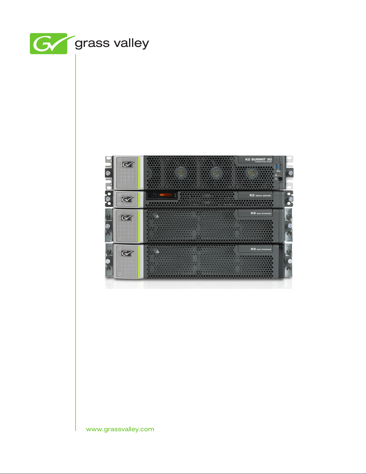
K2
10G Storage Area Network
Installation and Service Manual
Software Version 8.1
071-8779-01
February 2012
Page 2

Affiliate with the N.V. KEMA in The Netherlands
CERTIFICATE
Certificate Number: 510040.001
The Quality System of:
Thomson Inc, and its worLdwide Grass Valley division affiliates DBA
GRASS VALLEY
Headquarters
400 Providence Mine Rd
Nevada City, CA 95959
United States
15655 SW Greystone Ct.
Beaverton, OR 97006
United States
10 Presidential Way
Suite 300
Woburn, MA 01801
United States
Kapittelweg 10
4827 HG Breda
The Nederlands
7140 Baymeadows Way
Ste 101
Jacksonville, FL 32256
United States
2300 So. Decker Lake Blvd.
Salt Lake City, UT 84119
United States
Rue du Clos Courtel
CS 31719
35517 Cesson-Sevigné Cedex
France
1 rue de l’Hautil
Z.I. des Boutries BP 150
78702 Conflans-Sainte
Honorine Cedex
France
Technopole Brest-Iroise
Site de la Pointe du Diable
CS 73808
29238 Brest Cedex 3
France
40 Rue de Bray
2 Rue des Landelles
35510 Cesson Sevigné
France
Spinnereistrasse 5
CH-5300 Turgi
Switzerland
Brunnenweg 9
D-64331 Weiterstadt
Germany
Carl-Benz-Strasse 6-8
67105 Schifferstadt
Germany
Including its implementation, meets the requirements of the standard:
ISO 9001:2008
Scope:
The design, manufacture and support of video and audio hardware and software products and
related systems
.
This Certificate is valid until: June 14, 2012
This Certificate is valid as of: June 14, 2009
Certified for the first time: June 14, 2000
H. Pierre Sallé
President
KEMA-Registered Quality
The method of operation for quality certification is defined in the KEMA General Terms
And Conditions For Quality And Environmental Management Systems Certifications.
Integral publication of this certificate is allowed.
KEMA-Registered Quality, Inc.
4377 County Line Road
Chalfont, PA 18914
Ph: (215)997-4519
Fax: (215)997-3809
CRT 001 073004
Accredited By:
ANAB
CERTIFICATE
Certificate Number: 510040.001
The Quality System of:
Grass Valley USA, LLC and its Grass Valley Affiliates
Headquarters:
400 Providence Mine Road
Nevada City, CA 95945
United States
15655 SW Greystone Ct.
Beaverton, OR 97006
United States
Brunnenweg 9
D-64331 Weiterstadt
Germany
Kapittelweg 10
4827 HG Breda
The Nederlands
2300 So. Decker Lake Blvd.
Salt Lake City, UT 84119
United States
Including its implementation, meets the requirements of the standard:
ISO 9001:2008
Scope:
The design, manufacture and support of video and audio hardware and software products and related
systems.
This Certificate is valid until: June 14, 2012
This Certificate is valid as of: December 23, 2010
Certified for the first time: June 14, 2000
H. Pierre Sallé
President
KEMA-Registered Quality
The method of operation for quality certification is defined in the KEMA General Terms And Conditions For
Quality And Environmental Management Systems Certifications. Integral publication of this certificate is allowed.
KEMA-Registered Quality, Inc.
4377 County Line Road
Chalfont, PA 18914
Ph: (215)997-4519
Fax: (215)997-3809
CRT 001 042108
ccredited By:
ANAB
A
Page 3

K2
10G Storage Area Network
Installation and Service Manual
Software Version 8.1
071-8779-01
February 2012
Page 4

Contacting Grass Valley
International
Support Centers
Local Support
Centers
(available
during normal
business hours)
France
24 x 7
Australia and New Zealand: +61 1300 721 495 Central/South America: +55 11 5509 3443
Middle East: +971 4 299 64 40 Near East and Africa: +800 8080 2020 or +33 1 48 25 20 20
Europe
+800 8080 2020 or +33 1 48 25 20 20
Hong Kong, Taiwan, Korea, Macau: +852 2531 3058 Indian Subcontinent: +91 22 24933476
Asia
Southeast Asia/Malaysia: +603 7805 3884 Southeast Asia/Singapore: +65 6379 1313
China: +861 0660 159 450 Japan: +81 3 5484 6868
Belarus, Russia, Tadzikistan, Ukraine, Uzbekistan: +7 095 2580924 225 Switzerland: +41 1 487 80 02
S. Europe/Italy-Roma: +39 06 87 20 35 28 -Milan: +390248414658 S. Europe/Spain: +34 91 512 03 50
Benelux/Belgium: +32 (0) 2 334 90 30 Benelux/Netherlands: +31 (0) 35 62 38 42 1 N. Europe: +4545968870
Germany, Austria, Eastern Europe: +49 6150 104 444 UK, Ireland, Israel: +44 118 923 0499
Copyright © Grass Valley USA, LLC. All rights reserved.
This product may be covered by one or more U.S. and foreign patents.
United States/Canada
24 x 7
+1 800 547 8949 or +1 530 478 4148
Grass Valley Web Site
The www.grassvalley.com web site offers the following:
Online User Documentation — Current versions of product catalogs, brochures,
data sheets, ordering guides, planning guides, manuals, and release notes
in .pdf format can be downloaded.
FAQ Database — Solutions to problems and troubleshooting efforts can be
found by searching our Frequently Asked Questions (FAQ) database.
Software Downloads — Download software updates, drivers, and patches.
4 K2 Installation and Service Manual
Page 5

Contents
Safety Summaries......................................................................................................................................11
Preface.......................................................................................................................................................23
Chapter 1: Product description................................................................................................29
K2 SAN overview description.................................................................................................................30
K2 SAN key features...............................................................................................................................30
What's new in the K2 10G SAN..............................................................................................................31
K2 Storage types and terms...................................................................................................................32
K2 SAN descriptions...............................................................................................................................32
Basic K2 SAN description...................................................................................................................33
Redundant K2 SAN description..........................................................................................................34
Basic Nearline K2 SAN description.....................................................................................................35
Redundant Nearline K2 SAN description............................................................................................36
Chapter 2: Preparing for installation.......................................................................................39
K2 SAN installation checklists................................................................................................................40
Pre-installation planning checklist.......................................................................................................40
Infrastructure checklist........................................................................................................................40
Network setup and implementation checklist......................................................................................40
Software update checklist...................................................................................................................41
SAN configuration checklist.................................................................................................................42
Understanding system concepts.............................................................................................................42
Control network description.................................................................................................................42
Streaming/FTP network description....................................................................................................43
Media (iSCSI) network description......................................................................................................44
Networking tips....................................................................................................................................44
Network considerations and constraints.............................................................................................44
About host files....................................................................................................................................45
Host Table tips.....................................................................................................................................45
Chapter 3: Cabling K2 SAN devices........................................................................................47
To follow cabling instructions..................................................................................................................48
Basic K2 SAN - Online or Production.....................................................................................................48
Redundant K2 SAN - Online or Production............................................................................................49
Basic Nearline K2 SAN...........................................................................................................................50
Redundant Nearline K2 SAN..................................................................................................................50
Cable K2 Summit system.......................................................................................................................51
K2-XDP basic......................................................................................................................................51
K2-XDP redundant..............................................................................................................................51
Cable Ethernet switch.............................................................................................................................52
K2-SWE basic online/production.........................................................................................................52
K2-SWE redundant online/production.................................................................................................53
K2-SWE basic nearline.......................................................................................................................54
K2-SWE redundant nearline...............................................................................................................54
Cable K2 Media Server...........................................................................................................................55
K2-SVR basic......................................................................................................................................55
K2-SVR redundant..............................................................................................................................55
Cable NH10GE K2 Media Server...........................................................................................................56
K2-SVR-NH10GE online/production...................................................................................................56
K2-SVR-NH10GE basic nearline........................................................................................................57
02 February 2012 K2 SAN Installation and Service Manual 5
Page 6

Contents
K2-SVR-NH10GE redundant nearline.................................................................................................57
Cable K2 RAID.......................................................................................................................................57
K2 RAID basic online/production........................................................................................................58
K2 RAID redundant online/production.................................................................................................59
K2 RAID basic nearline.......................................................................................................................59
K2 RAID redundant nearline...............................................................................................................60
Chapter 4: Setting up the K2 SAN infrastructure...................................................................63
Setting up the Ethernet switch................................................................................................................64
Configuring the Ethernet switch via serial connection.........................................................................64
Configuring the Ethernet switch via the Web interface........................................................................67
Configuring QOS on the GigE switch..................................................................................................73
Verify flow control setting on the GigE switch......................................................................................74
Upgrading firmware on HP switch.......................................................................................................75
Setting up the control point PC...............................................................................................................76
To fix NetCentral screen resolution problem.......................................................................................77
Install SiteConfig on control point PC..................................................................................................77
Chapter 5: Planning and implementing a K2 SAN with SiteConfig......................................81
About developing a system description..................................................................................................82
Importing a system description...............................................................................................................82
About device and host names................................................................................................................83
Modifying a device name........................................................................................................................83
Modifying the control network.................................................................................................................83
Modifying the FTP/streaming network....................................................................................................85
Modifying a media (iSCSI) network........................................................................................................87
About IP configuration of network interfaces on devices........................................................................89
Placeholder device IP configuration....................................................................................................90
Discovered device IP configuration.....................................................................................................90
Modifying K2 client unassigned (unmanaged) interface.........................................................................91
Modifying K2 Media Server unassigned (unmanaged) interface............................................................93
About SiteConfig support on K2 devices................................................................................................96
Discovering devices with SiteConfig.......................................................................................................96
Assigning discovered devices.................................................................................................................97
Modifying K2 client managed network interfaces...................................................................................98
Modifying K2 Media Server managed network interfaces....................................................................103
Making the host name the same as the device name...........................................................................108
Pinging devices from the PC that hosts SiteConfig..............................................................................109
About hosts files and SiteConfig...........................................................................................................109
Generating host tables using SiteConfig...............................................................................................110
Chapter 6: Managing K2 Software.........................................................................................113
Configuring K2 software deployment....................................................................................................114
Configuring deployment groups........................................................................................................114
Adding a software package to a deployment group..........................................................................115
Checking all currently installed software on devices.........................................................................115
About deploying software for the K2 SAN.........................................................................................116
Backup and Recovery Strategies..........................................................................................................116
About the recovery disk image process............................................................................................116
Recommended recovery process.....................................................................................................117
Creating a recovery disk image for storing on E:..............................................................................118
Restoring from a system-specific recovery disk image on E:............................................................119
Restoring from the generic recovery disk image on E:.....................................................................120
Installing the Discovery Agent on a K2 Media Server.......................................................................122
Setting up Windows...........................................................................................................................123
Activating the Windows operating system.........................................................................................123
6 K2 SAN Installation and Service Manual 02 February 2012
Page 7

Contents
Chapter 7: Configuring and licensing the K2 SAN...............................................................125
About K2 SAN licensing........................................................................................................................126
About QOS on the K2 SAN...................................................................................................................126
Importing a SiteConfig system description...........................................................................................127
Configuring the basic K2 SAN - Online and Production.......................................................................127
Prerequisites for initial configuration - Basic K2 SAN........................................................................127
Defining a new K2 SAN.....................................................................................................................129
Configuring the server - Part 1..........................................................................................................132
Configuring RAID..............................................................................................................................136
Configuring the server - Part 2..........................................................................................................142
Configuring optional NH servers.......................................................................................................147
Configuring the redundant K2 SAN - Online and Production................................................................151
Prerequisites for initial configuration - Redundant K2 SAN...............................................................151
Defining a new K2 SAN.....................................................................................................................153
Configuring server A - Part 1.............................................................................................................156
Configuring RAID..............................................................................................................................160
Configuring server A - Part 2.............................................................................................................169
Configuring server B.........................................................................................................................173
Configuring optional NH servers.......................................................................................................181
Configuring the basic nearline K2 SAN................................................................................................187
Prerequisites for initial configuration - Basic nearline K2 SAN..........................................................187
Defining a new K2 SAN.....................................................................................................................188
Configuring NH server - Part 1..........................................................................................................192
Configuring RAID..............................................................................................................................196
Configuring NH server - Part 2..........................................................................................................203
Configuring the redundant nearline K2 SAN........................................................................................205
Prerequisites for initial configuration - Nearline K2 SAN...................................................................205
Defining a new K2 SAN.....................................................................................................................206
Configuring NH server A - Part 1......................................................................................................210
Configuring RAID..............................................................................................................................214
Configuring NH server A - Part 2......................................................................................................221
Configuring NH server B...................................................................................................................223
Chapter 8: Configuring clients on the K2 SAN.....................................................................229
About iSCSI bandwidth.........................................................................................................................230
Determining K2 client bandwidth requirements....................................................................................230
K2 SAN prerequisites for adding clients...............................................................................................230
Verify license on K2 Media Server....................................................................................................231
Preparing K2 clients..........................................................................................................................231
Installing Multi-Path I/O Software......................................................................................................232
Configuring a K2 client for the K2 Storage System..............................................................................233
Configure page 1 - K2 client..............................................................................................................234
Configure Software Configuration page - K2 client...........................................................................235
Configure Network Configuration page - K2 client............................................................................236
Configure Database Client Configuration page - K2 client................................................................237
Configure File System Client Configuration page.............................................................................238
Configure iSCSI Initiator Configuration page - K2 client...................................................................239
Adding a generic client device..............................................................................................................241
Assigning a SAN client to different FTP server.....................................................................................241
Powering on/off a SAN client................................................................................................................242
Taking a SAN client offline....................................................................................................................242
Chapter 9: Operating the K2 SAN..........................................................................................243
Powering off the K2 SAN......................................................................................................................244
Power off K2 Media Servers..............................................................................................................244
02 February 2012 K2 SAN Installation and Service Manual 7
Page 8

Contents
Power off K2 RAID............................................................................................................................245
Power off remaining K2 SAN devices................................................................................................245
Powering on the K2 SAN......................................................................................................................245
Basic K2 SAN power on procedure...................................................................................................246
Redundant K2 SAN power on procedure..........................................................................................247
Nearline K2 SAN power on procedure..............................................................................................249
Powering on the HP ProCurve switch...............................................................................................250
Powering on the control point PC......................................................................................................250
Failover behaviors.................................................................................................................................250
Pre-failover behavior.........................................................................................................................251
Control Team failover behavior..........................................................................................................251
K2 client media (iSCSI) connection failover behavior........................................................................252
K2 Media Server failover behavior....................................................................................................254
K2 Media Server failover with Control team failover behavior...........................................................255
Chapter 10: Description of K2 SAN Devices.........................................................................257
Device terminology...............................................................................................................................258
Control point PC description.................................................................................................................258
K2 Ethernet switch description.............................................................................................................259
K2 Ethernet switch specifications......................................................................................................259
K2 Media Server description.................................................................................................................260
K2 Media Server specifications.........................................................................................................260
NH K2 Media Server.............................................................................................................................261
NH K2 Media Server specifications...................................................................................................261
K2 RAID storage description................................................................................................................261
Chapter 11: Overview of K2 Storage Tools...........................................................................263
About SiteConfig...................................................................................................................................264
Opening SiteConfig...........................................................................................................................264
SiteConfig main window....................................................................................................................264
K2Config...............................................................................................................................................265
Opening the K2Config application.....................................................................................................266
Server Control Panel.............................................................................................................................267
Storage Utility for K2 SAN.....................................................................................................................268
About RANKs and LUNs in Storage Utility........................................................................................269
NetCentral.............................................................................................................................................269
Windows Remote Desktop Connection................................................................................................270
Accessing Remote Desktop Connection...........................................................................................270
Chapter 12: Administering and maintaining the K2 SAN....................................................271
Passwords and security on Grass Valley systems................................................................................272
About application security on the K2 SAN........................................................................................272
Modifying K2 SAN settings...................................................................................................................273
Accessing K2 SAN features..............................................................................................................274
About SiteConfig and K2Config settings...........................................................................................274
Renaming a K2 SAN.........................................................................................................................276
Adding devices to a K2 SAN.............................................................................................................276
Removing a K2 SAN.........................................................................................................................278
Accessing a K2 SAN from multiple PCs............................................................................................278
Taking a K2 SAN offline....................................................................................................................279
Bringing a K2 SAN online..................................................................................................................279
Viewing iSCSI assignments..............................................................................................................280
Using reference files..........................................................................................................................280
Managing redundancy on a K2 SAN....................................................................................................281
Identifying current primary/backup K2 Media Servers......................................................................281
Triggering an intentional failover........................................................................................................283
8 K2 SAN Installation and Service Manual 02 February 2012
Page 9

Contents
Recovering from a failover.................................................................................................................284
Working with K2 Media Servers............................................................................................................284
Accessing K2 Media Server features in the K2Config application ...................................................285
Taking a K2 Media Server out of service...........................................................................................285
Using the Stop button in Server Control Panel..................................................................................286
Placing a K2 Media Server in service ..............................................................................................287
Shutting down or restarting a K2 Media Server................................................................................287
Identifying K2 Media Server software versions.................................................................................287
Modifying K2 Media Server network settings....................................................................................287
Configuring Server 2008 for domain.................................................................................................288
Restoring network configuration........................................................................................................289
Removing a K2 Media Server...........................................................................................................293
Replacing a K2 Media Server...........................................................................................................293
Replacing an iSCSI interface adapter (TOE card)............................................................................295
Installing the Fibre Channel card driver............................................................................................296
Recovering from a failed K2 Media Server system battery...............................................................296
Checking K2 Media Server services.................................................................................................297
Licensing a K2 Media Server............................................................................................................299
Working with K2 clients.........................................................................................................................301
Accessing K2 client features in the K2Config application ................................................................301
Shutting down or restarting a K2 client.............................................................................................302
Taking a K2 client offline...................................................................................................................302
Bringing a K2 client online ................................................................................................................302
Adding a K2 client.............................................................................................................................302
Removing a K2 client........................................................................................................................303
Identifying K2 client software versions..............................................................................................303
Modifying K2 client control network settings.....................................................................................304
Modifying K2 client media (iSCSI) network settings..........................................................................304
Enabling and disabling the write filter using K2Config......................................................................305
Configure live streaming multicast using K2Config...........................................................................306
Using Storage Utility.............................................................................................................................308
Accessing Storage Utility..................................................................................................................308
Overview of Storage Utility................................................................................................................309
Working on the media file system and database..................................................................................309
Checking the media file system........................................................................................................310
Cleaning unreferenced files and movies...........................................................................................310
Making a new media file system.......................................................................................................311
Expanding the media file system by capacity...................................................................................313
Expanding the media file system by bandwidth................................................................................314
Recovering the media database.......................................................................................................319
Working with RAID storage...................................................................................................................320
Checking RAID storage subsystem status........................................................................................321
Checking controller microcode..........................................................................................................321
Identifying disks.................................................................................................................................321
Get controller logs.............................................................................................................................323
Unbind RANK....................................................................................................................................324
About full/background bind................................................................................................................325
Bind RANK........................................................................................................................................325
Binding Hot Spare drives..................................................................................................................327
Loading RAID controller and expansion chassis microcode.............................................................327
Downloading disk drive firmware......................................................................................................328
Replacing a disk module...................................................................................................................329
Replacing a controller.......................................................................................................................330
Configuring RAID chassis network and SNMP settings....................................................................331
Working with Ethernet switches............................................................................................................333
Design considerations for Ethernet switches....................................................................................333
Configuring a switch through the K2Config application ....................................................................335
Verifying spanning tree settings........................................................................................................335
02 February 2012 K2 SAN Installation and Service Manual 9
Page 10

Contents
Upgrading firmware on HP switch.....................................................................................................338
Appendix A: Custom K2 SAN systems.................................................................................341
About custom K2 SAN systems............................................................................................................342
About custom K2 SAN information.......................................................................................................342
System diagrams..................................................................................................................................342
iSCSI extended (redundant FSMs)...................................................................................................343
Fibre Channel connected clients (redundant FSMs).........................................................................344
Explanations and procedures...............................................................................................................345
General guidelines............................................................................................................................345
K2 RAID Fibre Channel port redundant configuration......................................................................345
Installing SANsurfer Switch Manager software.................................................................................347
Uninstalling SANsurfer Switch Manager software.............................................................................347
Fibre Channel switch domains..........................................................................................................347
Fibre Channel switch zoning.............................................................................................................347
Fibre Channel fabric cabling..............................................................................................................352
Appendix B: Trademarks and Agreements...........................................................................355
10 K2 SAN Installation and Service Manual 02 February 2012
Page 11

Safety Summaries
Safety Summary
Read and follow the important safety information below, noting especially those instructions related
to risk of fire, electric shock or injury to persons. Additional specific warnings not listed here may
be found throughout the manual.
WARNING: Any instructions in this manual that require opening the equipment cover
or enclosure are for use by qualified service personnel only. To reduce the risk of electric
shock, do not perform any servicing other than that contained in the operating instructions
unless you are qualified to do so.
Safety terms and symbols
Terms in this manual
Safety-related statements may appear in this manual in the following form:
WARNING: Warning statements identify conditions or practices that may result in
personal injury or loss of life.
CAUTION: Caution statements identify conditions or practices that may result in damage
to equipment or other property, or which may cause equipment crucial to your business
environment to become temporarily non-operational.
Terms on the product
These terms may appear on the product:
DANGER — A personal injury hazard is immediately accessible as you read the marking.
WARNING — A personal injury hazard exists but is not immediately accessible as you read the
marking.
CAUTION — A hazard to property, product, and other equipment is present.
Symbols on the product
The following symbols may appear on the product:
Indicates that dangerous high voltage is present within the equipment enclosure that may
be of sufficient magnitude to constitute a risk of electric shock.
Indicates that user, operator or service technician should refer to product manual(s) for
important operating, maintenance, or service instructions.
This is a prompt to note fuse rating when replacing fuse(s). The fuse referenced in the text
must be replaced with one having the ratings indicated.
02 February 2012 K2 SAN Installation and Service Manual 11
Page 12

Safety Summaries
Warnings
Identifies a protective grounding terminal which must be connected to earth ground prior
to making any other equipment connections.
Identifies an external protective grounding terminal which may be connected to earth
ground as a supplement to an internal grounding terminal.
Indicates that static sensitive components are present which may be damaged by electrostatic
discharge. Use anti-static procedures, equipment and surfaces during servicing.
The following warning statements identify conditions or practices that can result in personal injury
or loss of life.
Dangerous voltage or current may be present — Disconnect power and remove battery (if applicable)
before removing protective panels, soldering, or replacing components.
Do not service alone — Do not internally service this product unless another person capable of
rendering first aid and resuscitation is present.
Remove jewelry — Prior to servicing, remove jewelry such as rings, watches, and other metallic
objects.
Avoid exposed circuitry — Do not touch exposed connections, components or circuitry when power
is present.
Use proper power cord — Use only the power cord supplied or specified for this product.
Ground product — Connect the grounding conductor of the power cord to earth ground.
Operate only with covers and enclosure panels in place — Do not operate this product when covers
or enclosure panels are removed.
Use correct fuse — Use only the fuse type and rating specified for this product.
Use only in dry environment — Do not operate in wet or damp conditions.
Use only in non-explosive environment — Do not operate this product in an explosive atmosphere.
High leakage current may be present — Earth connection of product is essential before connecting
power.
Dual power supplies may be present — Be certain to plug each power supply cord into a separate
branch circuit employing a separate service ground. Disconnect both power supply cords prior to
servicing.
Double pole neutral fusing — Disconnect mains power prior to servicing.
Use proper lift points — Do not use door latches to lift or move equipment.
Avoid mechanical hazards — Allow all rotating devices to come to a stop before servicing.
Cautions
The following caution statements identify conditions or practices that can result in damage to
equipment or other property
Use correct power source — Do not operate this product from a power source that applies more than
the voltage specified for the product.
12 K2 SAN Installation and Service Manual 02 February 2012
Page 13

Safety Summaries
Use correct voltage setting — If this product lacks auto-ranging power supplies, before applying
power ensure that the each power supply is set to match the power source.
Provide proper ventilation — To prevent product overheating, provide equipment ventilation in
accordance with installation instructions.
Use anti-static procedures — Static sensitive components are present which may be damaged by
electrostatic discharge. Use anti-static procedures, equipment and surfaces during servicing.
Do not operate with suspected equipment failure — If you suspect product damage or equipment
failure, have the equipment inspected by qualified service personnel.
Ensure mains disconnect — If mains switch is not provided, the power cord(s) of this equipment
provide the means of disconnection. The socket outlet must be installed near the equipment and
must be easily accessible. Verify that all mains power is disconnected before installing or removing
power supplies and/or options.
Route cable properly — Route power cords and other cables so that they ar not likely to be damaged.
Properly support heavy cable bundles to avoid connector damage.
Use correct power supply cords — Power cords for this equipment, if provided, meet all North
American electrical codes. Operation of this equipment at voltages exceeding 130 VAC requires
power supply cords which comply with NEMA configurations. International power cords, if provided,
have the approval of the country of use.
Use correct replacement battery — This product may contain batteries. To reduce the risk of explosion,
check polarity and replace only with the same or equivalent type recommended by manufacturer.
Dispose of used batteries according to the manufacturer’s instructions.
Troubleshoot only to board level — Circuit boards in this product are densely populated with surface
mount technology (SMT) components and application specific integrated circuits (ASICS). As a
result, circuit board repair at the component level is very difficult in the field, if not impossible. For
warranty compliance, do not troubleshoot systems beyond the board level.
Sicherheit – Überblick
Lesen und befolgen Sie die wichtigen Sicherheitsinformationen dieses Abschnitts. Beachten Sie
insbesondere die Anweisungen bezüglich
Brand-, Stromschlag- und Verletzungsgefahren. Weitere spezifische, hier nicht aufgeführte
Warnungen finden Sie im gesamten Handbuch.
WARNUNG: Alle Anweisungen in diesem Handbuch, die das Abnehmen der
Geräteabdeckung oder des Gerätegehäuses erfordern, dürfen nur von qualifiziertem
Servicepersonal ausgeführt werden. Um die Stromschlaggefahr zu verringern, führen
Sie keine Wartungsarbeiten außer den in den Bedienungsanleitungen genannten Arbeiten
aus, es sei denn, Sie besitzen die entsprechende Qualifikationen für diese Arbeiten.
Sicherheit – Begriffe und Symbole
In diesem Handbuch verwendete Begriffe
Sicherheitsrelevante Hinweise können in diesem Handbuch in der folgenden Form auftauchen:
02 February 2012 K2 SAN Installation and Service Manual 13
Page 14

Safety Summaries
WARNUNG: Warnungen weisen auf Situationen oder Vorgehensweisen hin, die
Verletzungs- oder Lebensgefahr bergen.
VORSICHT: Vorsichtshinweise weisen auf Situationen oder Vorgehensweisen hin, die
zu Schäden an Ausrüstungskomponenten oder anderen Gegenständen oder zum zeitweisen
Ausfall wichtiger Komponenten in der Arbeitsumgebung führen können.
Hinweise am Produkt
Die folgenden Hinweise können sich am Produkt befinden:
GEFAHR – Wenn Sie diesen Begriff lesen, besteht ein unmittelbares Verletzungsrisiko.
WARNUNG – Wenn Sie diesen Begriff lesen, besteht ein mittelbares Verletzungsrisiko.
VORSICHT – Es besteht ein Risiko für Objekte in der Umgebung, den Mixer selbst oder andere
Ausrüstungskomponenten.
Symbole am Produkt
Die folgenden Symbole können sich am Produkt befinden:
Warnungen
Die folgenden Warnungen weisen auf Bedingungen oder Vorgehensweisen hin, die Verletzungsoder Lebensgefahr bergen:
Gefährliche Spannungen oder Ströme – Schalten Sie den Strom ab, und entfernen Sie ggf. die Batterie,
bevor sie Schutzabdeckungen abnehmen, löten oder Komponenten austauschen.
Weist auf eine gefährliche Hochspannung im Gerätegehäuse hin, die stark genug sein kann,
um eine Stromschlaggefahr darzustellen.
Weist darauf hin, dass der Benutzer, Bediener oder Servicetechniker wichtige Bedienungs-,
Wartungs- oder Serviceanweisungen in den Produkthandbüchern lesen sollte.
Dies ist eine Aufforderung, beim Wechsel von Sicherungen auf deren Nennwert zu achten.
Die im Text angegebene Sicherung muss durch eine Sicherung ersetzt werden, die die
angegebenen Nennwerte besitzt.
Weist auf eine Schutzerdungsklemme hin, die mit dem Erdungskontakt verbunden werden
muss, bevor weitere Ausrüstungskomponenten angeschlossen werden.
Weist auf eine externe Schutzerdungsklemme hin, die als Ergänzung zu einem internen
Erdungskontakt an die Erde angeschlossen werden kann.
Weist darauf hin, dass es statisch empfindliche Komponenten gibt, die durch eine
elektrostatische Entladung beschädigt werden können. Verwenden Sie antistatische
Prozeduren, Ausrüstung und Oberflächen während der Wartung.
Servicearbeiten nicht alleine ausführen – Führen Sie interne Servicearbeiten nur aus, wenn eine
weitere Person anwesend ist, die erste Hilfe leisten und Wiederbelebungsmaßnahmen einleiten kann.
Schmuck abnehmen – Legen Sie vor Servicearbeiten Schmuck wie Ringe, Uhren und andere
metallische Objekte ab.
14 K2 SAN Installation and Service Manual 02 February 2012
Page 15

Safety Summaries
Keine offen liegenden Leiter berühren – Berühren Sie bei eingeschalteter Stromzufuhr keine offen
liegenden Leitungen, Komponenten oder Schaltungen.
Richtiges Netzkabel verwenden – Verwenden Sie nur das mitgelieferte Netzkabel oder ein Netzkabel,
das den Spezifikationen für dieses Produkt entspricht.
Gerät erden – Schließen Sie den Erdleiter des Netzkabels an den Erdungskontakt an.
Gerät nur mit angebrachten Abdeckungen und Gehäuseseiten betreiben – Schalten Sie dieses Gerät
nicht ein, wenn die Abdeckungen oder Gehäuseseiten entfernt wurden.
Richtige Sicherung verwenden – Verwenden Sie nur Sicherungen, deren Typ und Nennwert den
Spezifikationen für dieses Produkt entsprechen.
Gerät nur in trockener Umgebung verwenden – Betreiben Sie das Gerät nicht in nassen oder feuchten
Umgebungen.
Gerät nur verwenden, wenn keine Explosionsgefahr besteht – Verwenden Sie dieses Produkt nur in
Umgebungen, in denen keinerlei Explosionsgefahr besteht.
Hohe Kriechströme – Das Gerät muss vor dem Einschalten unbedingt geerdet werden.
Doppelte Spannungsversorgung kann vorhanden sein – Schließen Sie die beiden Anschlußkabel an
getrennte Stromkreise an. Vor Servicearbeiten sind beide Anschlußkabel vom Netz zu trennen.
Vorsicht
Zweipolige, neutrale Sicherung – Schalten Sie den Netzstrom ab, bevor Sie mit den Servicearbeiten
beginnen.
Fassen Sie das Gerät beim Transport richtig an – Halten Sie das Gerät beim Transport nicht an Türen
oder anderen beweglichen Teilen fest.
Gefahr durch mechanische Teile – Warten Sie, bis der Lüfter vollständig zum Halt gekommen ist,
bevor Sie mit den Servicearbeiten beginnen.
Die folgenden Vorsichtshinweise weisen auf Bedingungen oder Vorgehensweisen hin, die zu Schäden
an Ausrüstungskomponenten oder anderen Gegenständen führen können:
Gerät nicht öffnen – Durch das unbefugte Öffnen wird die Garantie ungültig.
Richtige Spannungsquelle verwenden – Betreiben Sie das Gerät nicht an einer Spannungsquelle, die
eine höhere Spannung liefert als in den Spezifikationen für dieses Produkt angegeben.
Gerät ausreichend belüften – Um eine Überhitzung des Geräts zu vermeiden, müssen die
Ausrüstungskomponenten entsprechend den Installationsanweisungen belüftet werden. Legen Sie
kein Papier unter das Gerät. Es könnte die Belüftung behindern. Platzieren Sie das Gerät auf einer
ebenen Oberfläche.
Antistatische Vorkehrungen treffen – Es gibt statisch empfindliche Komponenten, die durch eine
elektrostatische Entladung beschädigt werden können. Verwenden Sie antistatische Prozeduren,
Ausrüstung und Oberflächen während der Wartung.
CF-Karte nicht mit einem PC verwenden – Die CF-Karte ist speziell formatiert. Die auf der CF-Karte
gespeicherte Software könnte gelöscht werden.
Gerät nicht bei eventuellem Ausrüstungsfehler betreiben – Wenn Sie einen Produktschaden oder
Ausrüstungsfehler vermuten, lassen Sie die Komponente von einem qualifizierten Servicetechniker
untersuchen.
02 February 2012 K2 SAN Installation and Service Manual 15
Page 16

Safety Summaries
Consignes desécurité
Kabel richtig verlegen – Verlegen Sie Netzkabel und andere Kabel so, dass Sie nicht beschädigt
werden. Stützen Sie schwere Kabelbündel ordnungsgemäß ab, damit die Anschlüsse nicht beschädigt
werden.
Richtige Netzkabel verwenden – Wenn Netzkabel mitgeliefert wurden, erfüllen diese alle nationalen
elektrischen Normen. Der Betrieb dieses Geräts mit Spannungen über 130 V AC erfordert Netzkabel,
die NEMA-Konfigurationen entsprechen. Wenn internationale Netzkabel mitgeliefert wurden, sind
diese für das Verwendungsland zugelassen.
Richtige Ersatzbatterie verwenden – Dieses Gerät enthält eine Batterie. Um die Explosionsgefahr zu
verringern, prüfen Sie die Polarität und tauschen die Batterie nur gegen eine Batterie desselben Typs
oder eines gleichwertigen, vom Hersteller empfohlenen Typs aus. Entsorgen Sie gebrauchte Batterien
entsprechend den Anweisungen des Batterieherstellers.
Das Gerät enthält keine Teile, die vom Benutzer gewartet werden können. Wenden Sie sich bei
Problemen bitte an den nächsten Händler.
Il est recommandé de lire, de bien comprendre et surtout de respecter les informations relatives à
la sécurité qui sont exposées ci-après, notamment les consignes destinées à prévenir les risques
d’incendie, les décharges électriques et les blessures aux personnes. Les avertissements
complémentaires, qui ne sont pas nécessairement repris ci-dessous, mais présents dans toutes les
sections du manuel, sont également à prendre en considération.
AVERTISSEMENT: Toutes les instructions présentes dans ce manuel qui concernent
l’ouverture des capots ou des logements de cet équipement sont destinées exclusivement
à des membres qualifiés du personnel de maintenance. Afin de diminuer les risques de
décharges électriques, ne procédez à aucune intervention d’entretien autre que celles
contenues dans le manuel de l’utilisateur, à moins que vous ne soyez habilité pour le
faire.
Consignes et symboles de sécurité
Termes utilisés dans ce manuel
Les consignes de sécurité présentées dans ce manuel peuvent apparaître sous les formes suivantes
:
AVERTISSEMENT: Les avertissements signalent des conditions ou des pratiques
susceptibles d’occasionner des blessures graves, voire même fatales.
MISE EN GARDE: Les mises en garde signalent des conditions ou des pratiques
susceptibles d’occasionner un endommagement à l’équipement ou aux installations, ou
de rendre l’équipement temporairement non opérationnel, ce qui peut porter préjudice
à vos activités.
Signalétique apposée sur le produit
La signalétique suivante peut être apposée sur le produit :
DANGER — risque de danger imminent pour l’utilisateur.
16 K2 SAN Installation and Service Manual 02 February 2012
Page 17

Safety Summaries
AVERTISSEMENT — Risque de danger non imminent pour l’utilisateur.
MISE EN GARDE — Risque d’endommagement du produit, des installations ou des autres équipements.
Symboles apposés sur le produit
Les symboles suivants peut être apposés sur le produit :
Signale la présence d’une tension élevée et dangereuse dans le boîtier de l’équipement ;
cette tension peut être suffisante pour constituer un risque de décharge électrique.
Signale que l’utilisateur, l’opérateur ou le technicien de maintenance doit faire référence
au(x) manuel(s) pour prendre connaissance des instructions d’utilisation, de maintenance
ou d’entretien.
Il s’agit d’une invite à prendre note du calibre du fusible lors du remplacement de ce dernier.
Le fusible auquel il est fait référence dans le texte doit être remplacé par un fusible du
même calibre.
Identifie une borne de protection de mise à la masse qui doit être raccordée correctement
avant de procéder au raccordement des autres équipements.
I dentifie une borne de protection de mise à la masse qui peut être connectée en tant que
borne de mise à la masse supplémentaire.
Avertissements
Les avertissements suivants signalent des conditions ou des pratiques susceptibles d’occasionner
des blessures graves, voire même fatales :
Présence possible de tensions ou de courants dangereux — Mettez hors tension, débranchez et
retirez la pile (le cas échéant) avant de déposer les couvercles de protection, de défaire une soudure
ou de remplacer des composants.
Ne procédez pas seul à une intervention d’entretien — Ne réalisez pas une intervention d’entretien
interne sur ce produit si une personne n’est pas présente pour fournir les premiers soins en cas
d’accident.
Retirez tous vos bijoux — Avant de procéder à une intervention d’entretien, retirez tous vos bijoux,
notamment les bagues, la montre ou tout autre objet métallique.
Évitez tout contact avec les circuits exposés — Évitez tout contact avec les connexions, les composants
ou les circuits exposés s’ils sont sous tension.
Utilisez le cordon d’alimentation approprié — Utilisez exclusivement le cordon d’alimentation fourni
avec ce produit ou spécifié pour ce produit.
Signale la présence de composants sensibles à l’électricité statique et qui sont susceptibles
d’être endommagés par une décharge électrostatique. Utilisez des procédures, des
équipements et des surfaces antistatiques durant les interventions d’entretien.
Raccordez le produit à la masse — Raccordez le conducteur de masse du cordon d’alimentation à
la borne de masse de la prise secteur.
Utilisez le produit lorsque les couvercles et les capots sont en place — N’utilisez pas ce produit si
les couvercles et les capots sont déposés.
02 February 2012 K2 SAN Installation and Service Manual 17
Page 18

Safety Summaries
Utilisez le bon fusible — Utilisez exclusivement un fusible du type et du calibre spécifiés pour ce
produit.
Utilisez ce produit exclusivement dans un environnement sec — N’utilisez pas ce produit dans un
environnement humide.
Utilisez ce produit exclusivement dans un environnement non explosible — N’utilisez pas ce produit
dans un environnement dont l’atmosphère est explosible.
Présence possible de courants de fuite — Un raccordement à la masse est indispensable avant la
mise sous tension.
Deux alimentations peuvent être présentes dans l’équipement — Assurez vous que chaque cordon
d’alimentation est raccordé à des circuits de terre séparés. Débranchez les deux cordons d’alimentation
avant toute intervention.
Fusion neutre bipolaire — Débranchez l’alimentation principale avant de procéder à une intervention
d’entretien.
Utilisez les points de levage appropriés — Ne pas utiliser les verrous de la porte pour lever ou déplacer
l’équipement.
Évitez les dangers mécaniques — Laissez le ventilateur s’arrêter avant de procéder à une intervention
d’entretien.
Mises en garde
Les mises en garde suivantes signalent les conditions et les pratiques susceptibles d’occasionner
des endommagements à l’équipement et aux installations :
N’ouvrez pas l’appareil — Toute ouverture prohibée de l’appareil aura pour effet d’annuler la garantie.
Utilisez la source d’alimentation adéquate — Ne branchez pas ce produit à une source d’alimentation
qui utilise une tension supérieure à la tension nominale spécifiée pour ce produit.
Assurez une ventilation adéquate — Pour éviter toute surchauffe du produit, assurez une ventilation
de l’équipement conformément aux instructions d’installation. Ne déposez aucun document sous
l’appareil – ils peuvent gêner la ventilation. Placez l’appareil sur une surface plane.
Utilisez des procédures antistatiques - Les composants sensibles à l’électricité statique présents dans
l’équipement sont susceptibles d’être endommagés par une décharge électrostatique. Utilisez des
procédures, des équipements et des surfaces antistatiques durant les interventions d’entretien.
N’utilisez pas la carte CF avec un PC — La carte CF a été spécialement formatée. Le logiciel enregistré
sur la carte CF risque d’être effacé.
N’utilisez pas l’équipement si un dysfonctionnement est suspecté — Si vous suspectez un
dysfonctionnement du produit, faites inspecter celui-ci par un membre qualifié du personnel
d’entretien.
Acheminez les câbles correctement — Acheminez les câbles d’alimentation et les autres câbles de
manière à ce qu’ils ne risquent pas d’être endommagés. Supportez correctement les enroulements
de câbles afin de ne pas endommager les connecteurs.
Utilisez les cordons d’alimentation adéquats — Les cordons d’alimentation de cet équipement, s’ils
sont fournis, satisfont aux exigences de toutes les réglementations régionales. L’utilisation de cet
équipement à des tensions dépassant les 130 V en c.a. requiert des cordons d’alimentation qui
satisfont aux exigences des configurations NEMA. Les cordons internationaux, s’ils sont fournis,
ont reçu l’approbation du pays dans lequel l’équipement est utilisé.
18 K2 SAN Installation and Service Manual 02 February 2012
Page 19

Utilisez une pile de remplacement adéquate — Ce produit renferme une pile. Pour réduire le risque
d’explosion, vérifiez la polarité et ne remplacez la pile que par une pile du même type, recommandée
par le fabricant. Mettez les piles usagées au rebut conformément aux instructions du fabricant des
piles.
Cette unité ne contient aucune partie qui peut faire l’objet d’un entretien par l’utilisateur. Si un
problème survient, veuillez contacter votre distributeur local.
Certifications and compliances
Canadian certified power cords
Canadian approval includes the products and power cords appropriate for use in the North America
power network. All other power cords supplied are approved for the country of use.
FCC emission control
This equipment has been tested and found to comply with the limits for a Class A digital device,
pursuant to Part 15 of the FCC Rules. These limits are designed to provide reasonable protection
against harmful interference when the equipment is operated in a commercial environment. This
equipment generates, uses, and can radiate radio frequency energy and, if not installed and used in
accordance with the instruction manual, may cause harmful interference to radio communications.
Operation of this equipment in a residential area is likely to cause harmful interference in which
case the user will be required to correct the interference at his own expense. Changes or modifications
not expressly approved by Grass Valley can affect emission compliance and could void the user’s
authority to operate this equipment.
Safety Summaries
Canadian EMC Notice of Compliance
This digital apparatus does not exceed the Class A limits for radio noise emissions from digital
apparatus set out in the Radio Interference Regulations of the Canadian Department of
Communications.
Le présent appareil numérique n’émet pas de bruits radioélectriques dépassant les limites applicables
aux appareils numériques de la classe A préscrites dans le Règlement sur le brouillage radioélectrique
édicté par le ministère des Communications du Canada.
EN55103 1/2 Class A warning
This product has been evaluated for Electromagnetic Compatibility under the EN 55103-1/2 standards
for Emissions and Immunity and meets the requirements for E4 environment.
This product complies with Class A (E4 environment). In a domestic environment this product may
cause radio interference in which case the user may be required to take adequate measures.
FCC emission limits
This device complies with Part 15 of the FCC Rules. Operation is subject to the following two
conditions: (1) This device may not cause harmful interference, and (2) this device must accept any
interference received, including interference that may cause undesirable operation.
02 February 2012 K2 SAN Installation and Service Manual 19
Page 20

Safety Summaries
Laser compliance
Laser safety requirements
This product may contain a Class 1 certified laser device. Operating this product outside specifications
or altering its original design may result in hazardous radiation exposure, and may be considered
an act of modifying or new manufacturing of a laser product under U.S. regulations contained in
21CFR Chapter 1, subchapter J or CENELEC regulations in HD 482 S1. People performing such
an act are required by law to recertify and reidentify this product in accordance with provisions of
21CFR subchapter J for distribution within the U.S.A., and in accordance with CENELEC HD 482
S1 for distribution within countries using the IEC 825 standard.
Laser safety
Laser safety in the United States is regulated by the Center for Devices and Radiological Health
(CDRH). The laser safety regulations are published in the “Laser Product Performance Standard,”
Code of Federal Regulation (CFR), Title 21, Subchapter J.
The International Electrotechnical Commission (IEC) Standard 825, “Radiation of Laser Products,
Equipment Classification, Requirements and User’s Guide,” governs laser products outside the
United States. Europe and member nations of the European Free Trade Association fall under the
jurisdiction of the Comité Européen de Normalization Electrotechnique (CENELEC).
Safety certification
This product has been evaluated and meets the following Safety Certification Standards:
ANSI/UL 60950-1
IEC 60950-1 with CB cert.
CAN/CSA C22.2 No. 60950-1
BS EN 60950-1
ESD Protection
Electronics today are more susceptible to electrostatic discharge (ESD) damage than older equipment.
Damage to equipment can occur by ESD fields that are smaller than you can feel. Implementing the
information in this section will help you protect the investment that you have made in purchasing
Grass Valley equipment. This section contains Grass Valley’s recommended ESD guidelines that
should be followed when handling electrostatic discharge sensitive (ESDS) items. These minimal
recommendations are based on the information in the Sources of ESD and Risks on page 21 area.
The information in Grounding Requirements for Personnel on page 22 is provided to assist you in
selecting an appropriate grounding method.
Designed/tested for compliance with:Standard
Safety of Information Technology Equipment, including
Electrical Business Equipment (Second edition 2007).
Safety of Information Technology Equipment, including
Electrical Business Equipment (Second edition, 2005).
Safety of Information Technology Equipment, including
Electrical Business Equipment (Second edition 2007).
Safety of Information Technology Equipment, including
Electrical Business Equipment 2006.
20 K2 SAN Installation and Service Manual 02 February 2012
Page 21

Recommended ESD Guidelines
Follow these guidelines when handling Grass Valley equipment:
• Only trained personnel that are connected to a grounding system should handle ESDS items.
• Do not open any protective bag, box, or special shipping packaging until you have been grounded.
NOTE: When a Personal Grounding strap is unavailable, as an absolute minimum, touch a
metal object that is touching the floor (for example, a table, frame, or rack) to discharge any
static energy before touching an ESDS item.
• Open the anti-static packaging by slitting any existing adhesive tapes. Do not tear the tapes off.
• Remove the ESDS item by holding it by its edges or by a metal panel.
• Do not touch the components of an ESDS item unless it is absolutely necessary to configure or
repair the item.
• Keep the ESDS work area clear of all nonessential items such as coffee cups, pens, wrappers
and personal items as these items can discharge static. If you need to set an ESDS item down,
place it on an anti-static mat or on the anti-static packaging.
Sources of ESD and Risks
Safety Summaries
The following information identifies possible sources of electrostatic discharge and can be used to
help establish an ESD policy.
Personnel
One of the largest sources of static is personnel. The static can be released from a person’s clothing
and shoes.
Environment
The environment includes the humidity and floors in a work area. The humidity level must be
controlled and should not be allowed to fluctuate over a broad range. Relative humidity (RH) is a
major part in determining the level of static that is being generated. For example, at 10% - 20% RH
a person walking across a carpeted floor can develop 35kV; yet when the relative humidity is
increased to 70% - 80%, the person can only generate 1.5kV.
Static is generated as personnel move (or as equipment is moved) across a floor’s surface. Carpeted
and waxed vinyl floors contribute to static build up.
Work Surfaces
Painted or vinyl-covered tables, chairs, conveyor belts, racks, carts, anodized surfaces, plexiglass
covers, and shelving are all static generators.
Equipment
Any equipment commonly found in an ESD work area, such as solder guns, heat guns, blowers,
etc., should be grounded.
Materials
Plastic work holders, foam, plastic tote boxes, pens, packaging containers and other items commonly
found at workstations can generate static electricity.
02 February 2012 K2 SAN Installation and Service Manual 21
Page 22

Safety Summaries
Grounding Requirements for Personnel
The information in this section is provided to assist you in selecting a grounding method. This
information is taken from ANSI/ESD S20.20-2007 (Revision of ANSI/ESD S20.20-1999).
Product Qualification
Required LimitsTest MethodPersonnel Grounding Technical
Requirement
< 3.5 x 10⁷ ohmANSI/ESD S1.1 (Section 5.11)Wrist Strap System*
< 3.5 x 10⁷ ohmANSI/ESD STM97.1Flooring / Footwear System –
Method 1
Flooring / Footwear System –
Method 2 (both required)
1ANSI/ESD STM97.2
< 109 ohmANSI/ESD STM97.
< 100 VANSI/ESD STM97.2
Product qualification is normally conducted during the initial selection of ESD control products and
materials. Any of the following methods can be used: product specification review, independent
laboratory evaluation, or internal laboratory evaluation.
Compliance Verification
Required LimitsTest MethodPersonnel Grounding Technical
Requirement
< 3.5 x 10⁷ ohmESD TR53 Wrist Strap SectionWrist Strap System*
Flooring / Footwear System –
Method 1
Flooring / Footwear System –
Method 2 (both required)
ESD TR53 Footwear Section
ESD TR53 Footwear Section
< 3.5 x 10⁷ ohmESD TR53 Flooring Section and
< 1.0 x 10⁹ ohmESD TR53 Flooring Section and
* For situations where an ESD garment is used as part of the wrist strap grounding path, the total
system resistance, including the person, garment, and grounding cord, must be less than 3.5 x 10
ohm.
7
22 K2 SAN Installation and Service Manual 02 February 2012
Page 23

Preface
About this document
This is a K2™ product manual. It describes the K2 10G Storage Area Network (SAN) and provides
instructions for installing and using the product in a variety of applications. The manual contains
information for K2 storage in both basic (non-redundant) and redundant configurations. Refer to
the sections that apply your K2 SAN's configuration. For custom K2 SANs that do not fit one of
these pre-defined levels, you must work with your Grass Valley representative for installation and
operation.
The K2 10G SAN, as documented with this manual, is characterized by 10 Gig iSCSI connections
and 8 Gig Fibre Channel connections. The K2 10G SAN requires K2 software version 7.3 and
higher. Some devices and/or systems used with older K2 SANs are not compatible with the K2 10G
SAN system. Consult "K2 Release Notes" for compatibility information.
For information on products that are compatible as clients to the K2 SAN, refer to those product’s
manuals, such as the "STRATUS Installation and Service Manual" and the "K2 FCP Connect
Installation Manual".
For more information
The following sections help you find the information you need in product manuals and elsewhere.
For the installer of a standalone K2 product with internal storage
If you are installing a K2 system, such as a K2 Summit/Solo system, with standalone internal storage,
refer to documentation in the following sequence:
For the installer of a K2 product with direct connect storage
In these formats:In these locations…Find this document…
PDF fileGrass Valley WebsiteK2 Release Notes1
PrintedK2 product shipping boxQuick Start Guide for the K2 product2
PDF fileK2 Documentation Set
PDF fileGrass Valley Website
PDF fileK2 Documentation SetK2 System Guide3
PDF fileGrass Valley Website
If you are installing a standalone K2 system, such as a K2 Summit system, with direct connect
external RAID storage, refer to documentation in the following sequence:
02 February 2012 K2 SAN Installation and Service Manual 23
Page 24

Preface
In these formats:In these locations…Find this document…
PDF fileGrass Valley WebsiteK2 Release Notes1
PrintedK2 RAID shipping boxK2 Storage Cabling Guide2
PDF fileK2 Documentation Set
PDF fileGrass Valley Website
PrintedK2 product shipping boxQuick Start Guide for the K2 product3
PDF fileK2 Documentation Set
PDF fileGrass Valley Website
PDF fileK2 Documentation SetK2 System Guide4
PDF fileGrass Valley Website
For the installer of K2 Summit systems with K2 SAN shared storage
If you are installing a K2 SAN with connected K2 Summit systems, refer to documentation in the
following sequence:
K2 Release Notes
Contains the latest information about the software shipped on your system, including software
upgrade instructions, software specifications and requirements, feature changes from the previous
releases, and any known problems. You should always check the Grass Valley Website to determine
if there is an updated version of release notes available.
In these formats:In these locations…Find this document…
PDF fileGrass Valley WebsiteK2 Release Notes1
PrintedK2 RAID shipping boxK2 Storage Cabling Guide2
PDF fileK2 Documentation Set
PDF fileGrass Valley Website
PrintedK2 product shipping boxQuick Start Guide for the K2 product3
PDF fileK2 Documentation Set
PDF fileGrass Valley Website
PDF fileK2 Documentation SetK2 SAN Installation and Service Manual4
PDF fileGrass Valley Website
PDF fileK2 Documentation SetK2 System Guide5
PDF fileGrass Valley Website
24 K2 SAN Installation and Service Manual 02 February 2012
Page 25

Quick Start Guides
The Quick Start Guide is a printed document, shipped in the product packaging with K2 Summit/Solo
systems and K2 Dyno Replay Controllers. The Quick Start Guide provides step-by-step installation
instructions for basic installation and operation of the product.
K2 Storage Cabling Guide
The K2 Storage Cabling Guide is a printed document, shipped in the product packaging with the
primary RAID storage chassis. The cabling guide provides instructions for K2 Storage Area Network
(SAN) cabling and external configuration. The cabling guide provides instructions for each level
of K2 SAN and covers both redundant and basic (non-redundant) systems. It also provides instructions
for connecting direct-connect external RAID storage to K2 Summit systems.
K2 Documentation Set
Except for the release notes, the full set of support documentation, including this manual, is available
in the K2 or K2/STRATUS Documentation Set. You can find the Documentation Set on the Grass
Valley website. The following URL allows you to browse by K2 software version:
Preface
http://www.grassvalley.com/dl/k2_summit
You can also find the Documentation Set on the USB Recovery Flash drive that ships with your K2
Summit/Solo system.
The Documentation Set includes the following K2 product documents:
K2 AppCenter User
Manual
Quick Start Guides
K2 System Guide
K2 SAN Installation and
Service Manual
K2 Storage Cabling Guide
Provides instructions for configuring and operating the media channels
of product.
The Quick Start Guide provides step-by-step installation instructions
for basic installation and operation of the product.
Contains the product specifications and instructions for modifying
system settings.
Contains information on servicing and maintaining the K2 product.K2 Service Manuals
Contains installation, configuration, and maintenance procedures for
shared storage options.
The cabling guide provides instructions for K2 Storage Area Network
(SAN) cabling and external configuration. The cabling guide provides
instructions for each level of K2 SAN and covers both redundant and
basic (non-redundant) systems. It also provides instructions for
connecting direct-connect external RAID storage to K2 Summit
systems.
RAID Instruction Manuals
Fibre Channel Switch
Installation Manual
02 February 2012 K2 SAN Installation and Service Manual 25
There is an Instruction Manual for each type of RAID storage device
that can be a part of a K2 SAN. These manuals contain procedures for
configuring and servicing the device.
Contains information on configuring and servicing the Fibre Channel
switch.
Page 26

Preface
SiteConfig User Manual
Contains information on using SiteConfig, Grass Valley’s system
management tool, for network configuration and software deployment.
On-line Help Systems
You can find documentation online with products as follows:
K2 AppCenter Help
NetCentral Help
SiteConfig Help
Contains information on using K2 AppCenter. In the AppCenter user
interface menu bar select Help, then choose AppCenter Help Topics
from the drop-down menu.
Contains information on using NetCentral. From the NetCentral
interface select Help | NetCentral Help Topics.
Contains information on using SiteConfig. In the SiteConfig user
interface menu bar select Help, then choose SiteConfig Help Topics
from the drop-down menu.
K2 FCP Connect documentation
The K2 FCP Connect product has its own documentation set, described as follows:
GV Connect User Manual
Provides instructions for using GV Connect, which is a Final Cut Pro
plugin, to access and work with K2 assets. GV Connect is part of the
K2 FCP Connect product.
GV Browse User Manual
K2 FCP Connect
Installation Manual
K2 FCP Connect Release
Notes
NetCentral documentation
The NetCentral product has its own documentation set, described as follows:
NetCentral Quick Start
Guide
NetCentral Installation
Guide
Provides instructions for using GV Browse, which is a Final Cut Pro
plugin, to access and work with assets on a MediaFrame server in an
Aurora Browse system. GV Connect is part of the K2 FCP Connect
product.
Provides detailed instructions to install and configure the K2 FCP
Connect product.
Contains the latest information about the K2 FCP Connect product,
including software upgrade instructions, software specifications and
requirements, feature changes from the previous releases, and any
known problems. You should always check the Grass Valley Website
to determine if there is an updated version of release notes available.
Provides an overview of the installation process to quickly set up and
run NetCentral.
Identifies requirements and procedures to correctly set up servers and
devices, as well as provides detailed instructions to install and configure
NetCentral software.
Describes how to use the NetCentral Manager to monitor devices.NetCentral User Guide
26 K2 SAN Installation and Service Manual 02 February 2012
Page 27
Preface
NetCentral Help
Grass Valley Website
This public Web site contains all the latest manuals and documentation, and additional support
information. Use the following URL.
http://www.grassvalley.com.
Dell Server Documentation
If your system includes a Grass Valley product on a Dell server platform, refer to the applicable
Grass Valley product manual for installation and configuration information. However, a full set of
Dell server documentation has been provided on the Dell Product Documentation CD-ROM. Refer
to the documents on this CD-ROM only as required by procedures in Grass Valley product manual.
Contains information on using NetCentral. From the NetCentral
interface select Help | NetCentral Help Topics.
Information referenced on the Dell Product Documentation CD-ROM includes, but is not limited
to:
• Unpacking and rack-mounting
• Important safety and regulatory information
• Status indicators, messages, and error codes
• Troubleshooting help
CAUTION: Do not use the Dell Quick Installation Guide provided with the Dell CD-ROM
package. This guide includes instructions for using the OpenManage software CD-ROM to
install an operating system, which is not necessary on the Grass Valley product.
02 February 2012 K2 SAN Installation and Service Manual 27
Page 28

Page 29

Chapter 1
Product description
This section contains the following topics:
• K2 SAN overview description
• K2 SAN key features
• What's new in the K2 10G SAN
• K2 Storage types and terms
• K2 SAN descriptions
02 February 2012 K2 SAN Installation and Service Manual 29
Page 30
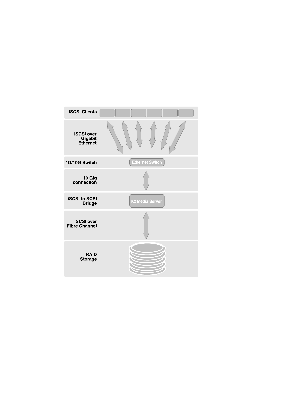
Product description
K2 SAN overview description
The K2 Storage Area Network (SAN) is Grass Valley’s shared storage solution that gives multiple
clients access to a common pool of media. In the iSCSI SAN, clients access the shared media storage
via a Gigabit Ethernet network and a Fibre Channel connection. Data is communicated using the
Small Computer System Interface (SCSI) data transfer interface and the Internet SCSI (iSCSI)
protocol.
A custom-designed Fibre Channel SAN is also available in which clients access RAID storage via
a Fibre Channel network, and the K2 Media Server connects via Ethernet for control functions only.
Refer to related topics in "K2 System Guide" for diagrams and explanations of the media file system
and the media database.
K2 SAN key features
The key features of the iSCSI K2 SAN are as follows:
• iSCSI storage access protocol
30 K2 SAN Installation and Service Manual 02 February 2012
Page 31

• Gigabit Ethernet connectivity
• RAID 5 and RAID 6 storage
• FTP transfers
• Enhanced IT networked storage configurations to fit a wide variety of size and performance
requirements.
• Scaling from 100 to < 5000 MB/s
• Redundancy and fault recovery with no single point of failure
• Tuned and optimized file system for reliable and robust transaction of media files
• Best in class storage management for high throughput, deterministic performance with load
balancing, priority of service, and quality of service
• Best in class support for 3rd party editors
What's new in the K2 10G SAN
The primary differences between the K2 10G SAN and previous K2 SANs are as follows:
• 8 Gig Fibre Channel — An 8 Gig Fibre Channel card in the K2 Media Server and an 8 Gig
controller in the K2 RAID support 8 Gig Fibre Channel connections. The K2 RAID chassis is
unchanged. The previous K2 SANs supported 2 Gig or 4 Gig Fibre Channel connections.
• 10 Gig iSCSI — A 10 Gig iSCSI interface adapter (TOE) in the K2 Media Server and a 10 Gig
SFP+ module in the Ethernet switch support a 10 Gig iSCSI connection. The 1 Gig iSCSI
connections between SAN clients and the Ethernet switch remain unchanged. The previous K2
SANs used multiple 1 Gig interface adapters and 1 Gig Ethernet switch ports to provide iSCSI
connections.
• K2 SAN simplification — The 10 Gig iSCSI connection allows most customer requirements to
be met by a simple K2 SAN with one K2 Media Server, or two K2 Media Servers if redundant.
The 1 Gig iSCSI connection of the previous K2 SANs needed multiple K2 Media Servers to
meet customer requirements for higher bandwidth.
• K2 SAN license — A license enables bandwidth in increments for a single 10 Gig iSCSI interface
adapter, rather than requiring multiple iSCSI interface adapters as in the previous K2 SANs.
• 64-bit K2 Media Server — The 64-bit operating system supports increased performance. The
previous K2 Media Servers were 32-bit devices only.
• Third level of Quality of Service (QOS) — Editors and other generic file system clients can be
assigned their own portion of K2 SAN bandwidth. The previous K2 SANs required additional
iSCSI interface adapters to statically manage this type of bandwidth.
Product description
If you are familiar with previous K2 SANs, keep these differences in mind as you read about the
K2 10G SAN in this manual. If you need information about previous K2 SANs, refer to previous
versions of this manual.
Related Topics
K2 SAN descriptions on page 32
About K2 SAN licensing on page 126
K2 Media Server description on page 260
About QOS on the K2 SAN on page 126
02 February 2012 K2 SAN Installation and Service Manual 31
Page 32

Product description
K2 Storage types and terms
Grass Valley configures K2 storage to meet their customer’s workflow needs. This topic describes
some typical configurations and terminology.
Online – Online storage is considered “Tier 1” K2 storage in that it is suitable for both record and
play. The purpose of an online SAN is to record and play media for broadcast or other on-air
applications. Performance requirements are critical for online applications, so this type of SAN
features high performance, low latency storage. Online storage can be iSCSI or Fibre Channel.
Production – Production storage is considered “Tier 2” K2 storage in that it is suitable for record
(ingest) but not recommended for on-air playout. The purpose of production storage is to provide
cost effective storage for production and editing applications. These applications require high
performance but internal buffering in editing software puts less stress on the storage system, so
performance requirements are lower than for online storage. Therefore, production storage can use
low cost, high capacity drives, such as 7.2K SAS drives. In a typical workflow, production is finished
on the production storage and then the content is pushed to an online K2 system for playout.
Production storage is configured similar to Online storage, but with the 7.2K SAS RAID devices
and drives. Production storage can be iSCSI or Fibre Channel.
Nearline – Nearline storage is considered “Tier 3” K2 storage in that it is suitable for media file
transfer but does not support either record or play. The purpose of a nearline SAN is to provide a
large pool of storage to which files can be saved. The nearline system is considered an “offline”
system, which means the system stores files only, such GXF files or MXF files, with no ability to
record or play those files directly on the system. The files on a nearline system can be readily
available to an online K2 system via FTP or CIFS connections over Ethernet. Nearline storage has
Fibre Channel connections between the K2 Media Server and the RAID storage devices.
Workgroup – Workgroup storage is a Fibre-Channel-only type of production storage intended for
small workgroups. This type of storage is no longer recommended, as technology advances provide
better value with standard iSCSI Production storage.
Live Production – In K2Config you can create a Live Production K2 SAN. This mode can be
applied to online and production SANs. A K2 SAN with LIve Production mode has a shorter
minimum delay between start record and start playout and is ideal for use with K2 Dyno. To support
this mode, Grass Valley must design your K2 SAN for increased bandwidth.
Stand-alone – This is not shared storage. It is the local storage for a K2 Media Client, K2 Summit
Production Client, or K2 Solo Media Server. Stand-alone storage can be internal media drives or
direct-connect K2 RAID devices. Refer to the K2 System Guide.
K2 SAN descriptions
The following sections describe the standard, pre-defined structures of the K2 SAN. Refer to related
topics in this document for more information on custom K2 SAN systems.
Related Topics
About custom K2 SAN systems on page 342
32 K2 SAN Installation and Service Manual 02 February 2012
Page 33

Basic K2 SAN description
RAID Primary
Chassis
RAID Expansion
Chassis (optional)
K2 Media Server
Ethernet Switch
Control
Media
Control
Media
Control
FTP
Media
Control point PC
K2 clients
Control
Control
FTP/streaming
Control
Media
Fibre Channel
NH Server
(optional)
Control
FTP
Product description
The basic (non-redundant) K2 SAN can be an online SAN or a production SAN. The SAN has one
Ethernet switch, one K2 Media Server, and one basic K2 RAID chassis. Up to eleven RAID
Expansion chassis are optional for increased storage capacity.
K2 clients and other iSCSI clients, such as Aurora Edits, are connected to the Ethernet switch. Each
K2 client has one GigE connection for media and one GigE connection for control. The GigE switch
is configured with V-LANs to keep the control/FTP traffic and the media (iSCSI) traffic separate.
The K2 Media Server has one 10 Gig connection for media (iSCSI), one GigE connection for control,
one GigE connection for FTP, and one Fibre Channel connection to the RAID storage. The server
hosts an iSCSI interface card for the 10 Gig media connection and a Fibre Channel card for the
RAID storage connection. The iSCSI interface card provides a bridge between iSCSI and Fibre
Channel SCSI. The server also hosts software components that allow it to function in various roles,
including media file system manager, media database server, and FTP server.
The basic K2 RAID chassis is connected via a single Fibre Channel connection to the K2 Media
Server. It is also connected to the GigE control network, which is required for SNMP (NetCentral)
monitoring.
Optional 10 Gig NH K2 Media Servers are available to provide additional FTP bandwidth. If the
optional NH server is used, all FTP traffic goes to this server, so the K2 Media Server is not cabled
or configured for FTP.
The K2Config control point PC is connected to the GigE control network. The K2Config application
runs on this PC for configuring the SAN. The SiteConfig application also runs on this PC.
02 February 2012 K2 SAN Installation and Service Manual 33
Page 34

RAID Primary
Chassis
RAID Expansion
Chassis (optional)
K2 Media
Servers
NH Servers
(optional)
A
B
BA
Ethernet
Switches
Fibre Channel
Control B
Media B
Control A
Media A
Control A
Media A
Control B
Media B
Control
FTP
Media
FTP
Control
Media
Control point PC
K2 clients
Control
ISLs
Control
Control
FTP/streaming
Control B
Media B
Control A
Media A
Fibre Channel
Control
FTP
Control
FTP
Product description
FTP/streaming traffic accesses the K2 SAN via the FTP GigE port on K2 Media Servers.
FTP/streaming traffic does not go to K2 clients.
Related Topics
Description of K2 SAN Devices on page 257
Working with Ethernet switches on page 333
Redundant K2 SAN description
34 K2 SAN Installation and Service Manual 02 February 2012
The redundant K2 SAN can be an online SAN or a production SAN. The SAN has two Ethernet
switches connected by Inter-Switch Links (ISLs) to support a redundant Ethernet fabric. The SAN
also has redundant K2 Media Servers. The servers are configured to have identical roles. This
provides redundancy for database, file system, iSCSI bridge, and FTP roles. One K2 RAID supports
redundant Fibre Channel connections. Up to eleven Expansion chassis are optional for increased
storage capacity.
K2 clients have a pair of redundant (teamed) Gigabit Ethernet ports for control and two Gigabit
Ethernet ports (A and B) for media (iSCSI). Each port of the control team is connected to a different
switch. The A media port goes to the A switch and the B media port goes to the B switch. The
switches are configured with V-LANs to keep the control/FTP and media (iSCSI) traffic separate.
Each K2 Media Server has one 10 Gig connection for media (iSCSI), one GigE connection for
control, one GigE connection for FTP, and one Fibre Channel connection to the RAID storage. All
GigE connections and the 10 Gig connection on a server go to the same GigE switch. The server
hosts a 10 Gig iSCSI interface card for the 10 Gig media connections and a Fibre Channel card for
the RAID storage connection. The iSCSI interface card provides a bridge between iSCSI and Fibre
Channel SCSI. The server also hosts software components that allow it to function in its roles,
Page 35

Control
RAID Chassis
RAID Expansion Chassis
NH K2 Media
Server
Ethernet
Switch
Fibre Channel
connection
Control
FTP
Control point PC
Control
FTP to/from online system
Product description
including media file system manager, media database server, and FTP server. Redundant K2 Media
Servers are connected by a serial cable which supports the heartbeat signal required for automatic
system recovery (failover) features.
The redundant K2 RAID chassis has redundant RAID controllers to support the Fibre Channel
connections from the K2 Media Servers. The redundant K2 RAID chassis is also connected to the
GigE control network, which is required for SNMP (NetCentral) monitoring.
On the redundant K2 RAID chassis there are two RAID 1 RANKs (also know as LUNs) for media
file system metadata files and journal files. The remainder of the RAID storage is RAID 5 or RAID
6 for media.
Optional 10 Gig NH K2 Media Servers are available to provide additional FTP bandwidth. If the
optional NH server is used, all FTP traffic goes to this server, so neither K2 Media Server is cabled
or configured for FTP.
The K2Config control point PC is connected to the GigE control network. The K2Config application
runs on this PC for configuring the SAN. The SiteConfig application also runs on this PC.
FTP/streaming traffic accesses the K2 SAN via the FTP GigE port on K2 Media Servers.
FTP/streaming traffic does not go to K2 clients.
Related Topics
Description of K2 SAN Devices on page 257
Working with Ethernet switches on page 333
Basic Nearline K2 SAN description
02 February 2012 K2 SAN Installation and Service Manual 35
The purpose of a Nearline SAN is to provide a large pool of storage to which files can be saved.
The Nearline system is considered an “offline” system, which means the system stores files only,
such GXF files or MXF files, with no ability to record or play those files directly on the system.
This is because the Nearline system has no media database to support “movies” or “clips”, such as
there is on an “online” K2 SAN. However, the files on a Nearline system can be readily available
to an online K2 system via FTP transfer.
Page 36

ISLs
Control
Control
RAID Chassis
RAID Expansion Chassis
NH K2 Media
Servers
Ethernet
Switches
Fibre Channel
connections
Control
FTP
Control
FTP
Control point PC
Control
FTP to/from online system
ISLs
A
A
B
B
Product description
The basic Nearline SAN has one Ethernet switch.
The SAN also has one 10 Gig NH K2 Media Server. The NH server for a Nearline system has two
ports for Fibre Channel connections. NH servers do not have media (iSCSI) ports.
A NH server on a Nearline system is configured with roles of FTP server and Media file system
server.
In the Nearline system no K2 Media Servers take the role of iSCSI bridge or media database server.
No K2 clients or any other generic client are part of the Nearline system.
7.2K SAS drives provide the media file storage on a Nearline system. While these drives do not
provide the high bandwidth of the drives required by an online K2 SAN, they offer larger capacity
and lower cost. This makes these drives ideal for the Nearline SAN.
The primary RAID chassis has one controller. The primary RAID chassis is connected via Fibre
Channel to the NH server. The controller in the RAID chassis is also connected to the GigE control
network, which is required for SNMP (NetCentral) monitoring.
There must be one primary RAID chassis and may be up to eleven optional Expansion chassis.
Primary chassis and Expansion chassis contain twelve drives. All disks in both primary and optional
Expansion chassis are bound as RAID 6.
The K2Config control point PC is connected to the GigE control network. The K2Config application
runs on this PC for configuring the SAN. The SiteConfig application also runs on this PC.
Related Topics
Description of K2 SAN Devices on page 257
Working with Ethernet switches on page 333
Redundant Nearline K2 SAN description
36 K2 SAN Installation and Service Manual 02 February 2012
The purpose of a Nearline SAN is to provide a large pool of storage to which files can be saved.
The Nearline system is considered an “offline” system, which means the system stores files only,
such GXF files or MXF files, with no ability to record or play those files directly on the system.
Page 37

Product description
This is because the Nearline system has no media database to support “movies” or “clips”, such as
there is on an “online” K2 SAN. However, the files on a Nearline system can be readily available
to an online K2 system via FTP transfer.
The redundant Nearline SAN has two Ethernet switches, connected by Inter-Switch Links (ISLs)
to support a redundant Ethernet fabric.
The SAN also has two 10 Gig NH K2 Media Servers. The NH server for a Nearline system has two
ports for Fibre Channel connections. NH servers do not have media (iSCSI) ports.
A NH server on a Nearline system is configured with roles of FTP server and Media file system
server. On a redundant system these roles are identical on both servers and provide redundancy as
follows:
• FTP server — Both servers are active in this role simultaneously. To provide FTP redundancy
in the event of a server failure, your facility’s FTP system must be able to access alternate FTP
servers.
• Media file system server — Only one server is active at any one time in this role, and the media
file system provides redundancy. If a fault occurs on the active server, one of the other servers
automatically takes over as the active media file system server.
In the Nearline system no K2 Media Servers take the role of iSCSI bridge or media database server.
No K2 clients or any other generic client are part of the Nearline system.
7.2K SAS drives provide the media file storage on a Nearline system. While these drives do not
provide the high bandwidth of the drives required by an online K2 SAN, they offer larger capacity
and lower cost. This makes these drives ideal for the Nearline SAN.
The primary RAID chassis has two controllers. The primary RAID chassis is connected via Fibre
Channel to the NH server. These Fibre Channel connections access the disks simultaneously for
redundancy and increased bandwidth. Each controller in the RAID chassis is also connected to the
GigE control network, which is required for SNMP (NetCentral) monitoring.
There must be one primary RAID chassis and may be up to eleven optional Expansion chassis.
Primary chassis and Expansion chassis contain twelve drives. All disks in both primary and optional
Expansion chassis are bound as RAID 6.
The K2Config control point PC is connected to the GigE control network. The K2Config application
runs on this PC for configuring the SAN. The SiteConfig application also runs on this PC.
Related Topics
Description of K2 SAN Devices on page 257
Working with Ethernet switches on page 333
02 February 2012 K2 SAN Installation and Service Manual 37
Page 38

Page 39

Chapter 2
Preparing for installation
This section contains the following topics:
• K2 SAN installation checklists
• Understanding system concepts
02 February 2012 K2 SAN Installation and Service Manual 39
Page 40

Preparing for installation
K2 SAN installation checklists
Use the following sequence of checklists to guide the overall task flow of installing and
commissioning a K2 SAN.
Pre-installation planning checklist
CommentInstructionsTask
Procure existing or create new
SiteConfig system description
Next: Infrastructure checklist
Infrastructure checklist
Rack and cable
Configure Ethernet switch(es)
Install/update SiteConfig on
control point PC
Clients, disable the write filter.
Next: Network setup and implementation checklist
About developing a system
description on page 82
page 47
on page 64
point PC on page 77
K2 System GuideFor K2 Summit Production
You can do this before
arriving at the customer site.
CommentInstructionsTask
—Cabling K2 SAN devices on
—Setting up the Ethernet switch
—Install SiteConfig on control
You must connect keyboard,
monitor, and mouse and do
this on each K2 Summit
Production Client before
managing with SiteConfig.
Network setup and implementation checklist
CommentInstructionsTask
Import or create the
SiteConfig system description
Importing a system description
on page 82
on the control point PC
Modify names and networks
in the SiteConfig system
description.
Modifying a device name on
page 83, Modifying the
control network on page 83,
Modifying the FTP/streaming
network on page 85,
Modifying a media (iSCSI)
network on page 87
40 K2 SAN Installation and Service Manual 02 February 2012
Select IP address range for
each network and each device
type.
Set subnet mask and other
settings.
Page 41

Preparing for installation
CommentInstructionsTask
Verify/modify device
interfaces
Discover devices
Assign placeholder devices to
discovered devices
Configure IP settings of
network interfaces on
discovered devices
Configure names
Validate networks
Modifying K2 client
unassigned (unmanaged)
interface on page 91,
Modifying K2 Media Server
unassigned (unmanaged)
interface on page 93
Discovering devices with
SiteConfig on page 96
on page 97
network interfaces on page
98, Modifying K2 Media
Server managed network
interfaces on page 103
same as the device name on
page 108
that hosts SiteConfig on page
109
Do not proceed until the
system description accurately
represents all aspects of the
actual system. Refer to
SiteConfig Help Topics . Use
procedures as appropriate for
your site.
Make sure the write filter is
disabled (device is unlocked)
on K2 Summit Production
Clients.
—Assigning discovered devices
—Modifying K2 client managed
—Making the host name the
—Pinging devices from the PC
Distribute host table
information
Next: Software update checklist
Software update checklist
Create deployment groups
Place software on control
point PC
Check software on devices
Upgrade/install software to
devices from control point PC
SiteConfig on page 110
groups on page 114
a deployment group on page
115
installed software on devices
About deploying software for
the K2 SAN on page 116
—Generating host tables using
CommentInstructionsTask
—Configuring deployment
—Adding a software package to
—Checking all currently
Refer to K2 Release Notes.
Make sure the write filter is
disabled (device is unlocked)
on K2 Summit Production
Clients.
02 February 2012 K2 SAN Installation and Service Manual 41
Page 42

Preparing for installation
Next: SAN configuration checklist
SAN configuration checklist
CommentInstructionsTask
CommentInstructionsTask
Import SiteConfig system
description into K2Config
Configure SAN in K2Config
Verify SAN license
Add K2 clients to SAN
K2 SAN installation complete
Understanding system concepts
Make sure you understand the following system concepts before planning or implementing a K2
SAN.
description on page 127
Configuring and licensing the
K2 SAN
Use the appropriate
instructions for your K2 SAN.
Verify license on K2 Media
Server on page 231
K2 Storage System on page 233
—Importing a SiteConfig system
Make sure the write filter is
disabled (device is unlocked)
on K2 Summit Production
Clients.
The K2 Media Server with
role of file system server must
be licensed for your SAN's
design and bandwidth
requirements.
—Configuring a K2 client for the
Control network description
The control network is for communication between devices and components. It does not have
real-time media traffic or streaming/FTP media traffic. The control network must be on a different
subnet than the streaming/FTP network and the media (iSCSI) network. The control network and
the streaming/FTP network may be on the same VLAN. The control network and the media (iSCSI)
network must not be on the same VLAN. Static IP addresses with name resolution via host files are
recommended for the control network.
The control network applies to both online, production, and nearline K2 SANs.
All the devices of the K2 SAN are on the control network. Stand-alone K2 clients can also be on
the same control network.
Redundant K2 SANs have one control network with hardware separated into an A side and a B side.
There is an A Ethernet switch and a B Ethernet switch. Switches are connected by InterSwitch Links
42 K2 SAN Installation and Service Manual 02 February 2012
Page 43

(ISLs or trunks) to provide redundant paths for control network traffic. On a redundant K2 SAN,
devices are on the control network as follows:
• Shared Storage K2 client - The two control GigE ports are configured as a team. The control
team shares a single IP address. One port of the team is on the A side and the other port of the
team is on the B side.
• K2 Media Server - Redundant K2 Media Servers with role of media file system/metadata server
are balanced between the A and B sides. One server is on the A side and the other server is on
the B side. K2 Media Servers with other roles, such as FTP server, are likewise balanced between
A and B sides.
• K2 RAID - When a K2 RAID device has redundant controllers, controller 0 is on the A side and
controller 1 is on the B side.
• Ethernet switch - For control and configuration, the A switch is on the A side and the B switch
is on the B side
Streaming/FTP network description
The streaming/FTP network is for media transfers and FTP traffic. It must be on a different subnet
than the control network and the media (iSCSI) network. The control network and the streaming/FTP
network may be on the same VLAN. The control network and the media (iSCSI) network must not
be on the same VLAN. Static IP addresses with name resolution via host files are recommended for
the streaming/FTP network. Hostnames of network adapters that are dedicated to the streaming/FTP
network must be aliased in the hosts file with the _he0 suffix. This directs the streaming traffic to
the correct port.
Preparing for installation
The streaming/FTP network applies to both online and nearline K2 SANs. For nearline systems,
this is the primary network for moving media to and from the storage system.
Redundant K2 SANs have one streaming/FTP network with hardware separated into an A side and
a B side. There is an A Ethernet switch and a B Ethernet switch. Switches are connected by
InterSwitch Links (ISLs) to provide redundant paths for streaming/FTP traffic.
Only those K2 devices that host a K2 FTP interface are on the streaming/FTP network, as follows:
• K2 Media Servers - Those with the role of FTP server are connected via their dedicated FTP
port. On a redundant K2 SAN, if you have multiple K2 Media Servers with role of FTP server,
balance servers between the A and B sides.
• Stand-alone K2 clients - While not a part of a K2 SAN, stand-alone K2 clients can also be on
the streaming/FTP network. Connect to the dedicated FTP port.
NOTE: Shared storage K2 clients are not on the streaming/FTP network. They do not have a
FTP interface and they do not send or receive streaming/FTP traffic.
Automatic FTP server failover is not provided by the K2 SAN. If you require automatic failover to
a redundant FTP server for your streaming/FTP traffic, you must provide it through your FTP
application.
02 February 2012 K2 SAN Installation and Service Manual 43
Page 44

Preparing for installation
Media (iSCSI) network description
The media network is exclusively for real-time iSCSI traffic on a K2 SAN. It must be on a different
subnet than the control network and the streaming/FTP network. Furthermore, its traffic is kept
physically separate from that of other networks. This separation is provided by dedicated ports,
cables, and by a dedicated VLAN on the Ethernet switch or by separate switches. Static IP addresses
are required for the media network. Name resolution is not necessary, so media network IP addresses
are not required in host files.
The media network applies to online K2 SANs. Nearline K2 SANs do not have a media network.
Redundant K2 SANs have redundant media networks: an A media network and a B media network.
The two networks are on separate subnets and are also physically separated onto the A Ethernet
switch and the B Ethernet switch. InterSwitch Links (ISLs) between switches do not carry media
(iSCSI) traffic. ISLs provide redundant paths for control network traffic and streaming/FTP network
traffic only.
Devices are on the media network as follows:
• Shared Storage K2 client - On a non-redundant K2 SAN, the A media port connects to the media
network. On a redundant K2 SAN, the A media port connects to the A media network and the
B media port connects to the B media network.
• K2 Media Server - A server has one port available for connection to a media network. This is a
10 Gig iSCSI interface adapter, which supports the functionality of a TCP/IP Offload Engine
(TOE). On a redundant K2 SAN, one server is on the A media network and one server is on the
B media network.
Networking tips
• Before configuring any devices for networks, determine the full scope of IP addresses and names
needed for the all the machines in your system. Work with the network administrator at your
facility to have IP addresses and names available for your use.
• It is recommended that you use the patterns offered in SiteConfig by default to establish a
consistent convention for machine names and IP addresses. You can plan, organize, and enter
this information in SiteConfig as you develop a system description. You can do this even before
you have devices installed and/or cabled.
• On 64-bit devices, configure IPv4 addresses. Disable the IPv6 interface of the Control and FTP
interfaces. SiteConfig always configures IPv4 addresses for 64-bit devices.
Network considerations and constraints
• Do not use any 10.1.0.n IP addresses. These are used by the K2 RAID (NEC Condor) maintenance
port and must be reserved for that purpose. If these addresses are otherwise used, maintenance
port communication errors occur.
44 K2 SAN Installation and Service Manual 02 February 2012
Page 45

About host files
The hosts file is used by the control network and the streaming/FTP network for name resolution,
which determines the IP address of a device on the network when only the device name (hostname)
is given. The hosts file is located at C:\Windows\system32\drivers\etc\hosts on Windows XP
and later operating systems. The hosts file must be the same on all network devices. It includes the
names and addresses of all the devices on the network.
For FTP transfers on a K2 SAN, transfers go to/from K2 Media Servers that have the role of FTP
server. No transfers go directly to/from the shared storage K2 clients that are on the K2 SAN. To
support FTP transfers, in the hosts file the K2 Media Server hostname must have the _he0 extension
added at the end of the name and that hostname must be associated with the K2 Media Server's
FTP/streaming network IP address.
Here is an example of IP addresses and names associated in a hosts file:
192.168.100.11 root_server_1
192.168.101.11 root_server_1_he0
192.168.100.21 root_server_2
192.168.101.21 root_server_2_he0
192.168.100.31 root_server_3
192.168.101.31 root_server_3_he0
192.168.100.41 root_server_4
192.168.101.41 root_server_4_he0
192.168.100.51 root_raid_1
192.168.100.61 root_gige_1
Preparing for installation
In this example 192.168.100.xx is the control network and 192.168.101.xx is the streaming/FTP
network. Each K2 Media Server has its hostname associated with its control network IP address. In
addition, each K2 Media Server (that has the role of FTP server) has its _he0 hostname associated
with its streaming/FTP network address.
Use SiteConfig to define your networks and devices. When you do so, SiteConfig creates the correct
hosts file and copies the hosts file to each network device. This enforces consistent hosts files across
networks and reduces errors introduced by editing and copying hosts files on individual devices.
You can also view hosts files from SiteConfig for troubleshooting purposes.
Host Table tips
• If transferring to or from a Profile XP or Open SAN system via UIM, the hosts file must also
follow UIM naming conventions for those systems. Refer to the UIM Instruction Manual.
• Do not enable name resolutions for media (iSCSI) network IP addresses in the hosts file, as
hostname resolution is not required for the media network. If desired, you can enter media network
information in the hosts file as commented text as an aid to managing your networks.
02 February 2012 K2 SAN Installation and Service Manual 45
Page 46

Preparing for installation
• Use the following tip with care. While it can solve a problem, it also introduces a name resolution
"anomaly" that might be confusing if not considered in future troubleshooting activities.
For each SAN (shared storage) K2 client, add the "_he0" suffix to the hostname but then associate
that hostname with the K2 Media Server's FTP/streaming network IP address, not the K2 client's
IP address. Aliasing K2 client hostnames in this way would not be required if the transfer
source/destination was always correctly specified as the K2 Media Server. However, a common
mistake is to attempt a transfer in which the source/destination is incorrectly specified as the K2
client. The host file aliasing corrects this mistake and redirects to the K2 Media Server, which
is the correct transfer source/destination.
An example of a hosts file entry with this type of aliasing is as follows:
192.168.101.11 server_1_he0 client_1_he0 client_2_he0
46 K2 SAN Installation and Service Manual 02 February 2012
Page 47

Chapter 3
Cabling K2 SAN devices
This section contains the following topics:
• To follow cabling instructions
• Basic K2 SAN - Online or Production
• Redundant K2 SAN - Online or Production
• Basic Nearline K2 SAN
• Redundant Nearline K2 SAN
• Cable K2 Summit system
• Cable Ethernet switch
• Cable K2 Media Server
• Cable NH10GE K2 Media Server
• Cable K2 RAID
02 February 2012 K2 SAN Installation and Service Manual 47
Page 48

RAID Primary
Chassis
RAID Expansion
Chassis (optional)
K2 Media Server
Ethernet Switch
Control
Media
Control
Media
Control
FTP
Media
Control point PC
K2 clients
Control
Control
FTP/streaming
Control
Media
Fibre Channel
NH Server
(optional)
Control
FTP
Cabling K2 SAN devices
To follow cabling instructions
To follow cabling instructions for your K2™ Storage Area Network (SAN), do the following:
1. Find the system cabling diagram that matches your K2 system.
2. Follow the references below the system diagram to locate cabling instructions for the individual
devices of your K2 system.
Basic K2 SAN - Online or Production
48 K2 SAN Installation and Service Manual 02 February 2012
To cable this K2 SAN device…
K2 Summit system
(optional)
This manual documents the default GigE switch configuration. Other configurations are available,
depending on your port count and FTP bandwidth requirements.
platform…
system or first
generation K2
Summit system
Turn to these instructions:Of this model or
K2-XDP basic on page 51K2 Summit 3G
K2-SWE basic online/production on page 52HP 2910Gigabit Ethernet Switch
K2-SVR basic on page 55Dell R610K2 Media Server
K2-SVR-NH10GE online/production on page 56Dell R610NH10GE K2 Media Server
K2 RAID basic online/production on page 58K2 RAIDK2 RAID
Page 49

Redundant K2 SAN - Online or Production
RAID Primary
Chassis
RAID Expansion
Chassis (optional)
K2 Media
Servers
NH Servers
(optional)
A
B
BA
Ethernet
Switches
Fibre Channel
Control B
Media B
Control A
Media A
Control A
Media A
Control B
Media B
Control
FTP
Media
FTP
Control
Media
Control point PC
K2 clients
Control
ISLs
Control
Control
FTP/streaming
Control B
Media B
Control A
Media A
Fibre Channel
Control
FTP
Control
FTP
Cabling K2 SAN devices
02 February 2012 K2 SAN Installation and Service Manual 49
To cable this K2 SAN device…
K2 Summit system
(optional)
This manual documents the default GigE switch configuration. Other configurations are available,
depending on your port count and FTP bandwidth requirements.
platform…
system or first
generation K2
Summit system
Turn to these instructions:Of this model or
K2-XDP redundant on page 51K2 Summit 3G
K2-SWE redundant online/production on page 53HP 2910Gigabit Ethernet Switch
K2-SVR redundant on page 55Dell R610K2 Media Server
K2-SVR-NH10GE online/production on page 56Dell R610NH10GE K2 Media Server
K2 RAID redundant online/production on page 59K2 RAIDK2 RAID
Page 50

Control
RAID Chassis
RAID Expansion Chassis
NH K2 Media
Server
Ethernet
Switch
Fibre Channel
connection
Control
FTP
Control point PC
Control
FTP to/from online system
ISLs
Control
Control
RAID Chassis
RAID Expansion Chassis
NH K2 Media
Servers
Ethernet
Switches
Fibre Channel
connections
Control
FTP
Control
FTP
Control point PC
Control
FTP to/from online system
ISLs
A
A
B
B
Cabling K2 SAN devices
Basic Nearline K2 SAN
To cable this K2 SAN device…
platform…
Redundant Nearline K2 SAN
Turn to these instructions:Of this model or
K2-SWE basic nearline on page 54HP 2910Gigabit Ethernet Switch
K2-SVR-NH10GE basic nearline on page 57Dell R610NH10GE K2 Media Server
K2 RAID basic nearline on page 59K2 10G RAIDK2 RAID
50 K2 SAN Installation and Service Manual 02 February 2012
To cable this K2 SAN device…
platform…
Turn to these instructions:Of this model or
K2-SWE redundant nearline on page 54HP 2910Gigabit Ethernet Switch
Page 51

!
OK
~AC
C1 C2 C3 C4
USB/1394
100BT/1000BT
GPI
VGA
REF.LOOP THROUGH
!
OK
~AC
To control port
on GigE switch
To media (iSCSI) port
on GigE switch
!
OK
~AC
C1 C2 C3 C4
USB/1394
100BT/1000BT
GPI
VGA
REF.LOOP THROUGH
!
OK
~AC
To control port
on GigE switch A
To control port
on GigE switch B
To media (iSCSI) port
on GigE switch A
To media (iSCSI) port
on GigE switch B
Cabling K2 SAN devices
To cable this K2 SAN device…
platform…
Cable K2 Summit system
As directed by the system diagram for your K2 storage, cable the K2 Summit system using the
instructions in this section.
K2-XDP basic
These cabling instructions apply to the following:
• K2 Summit 3G system or first generation K2 Summit system on a basic (non-redundant) online
or production K2 SAN
Refer to "K2 Summit Production Client Quick Start Guide" for additional cabling details.
Turn to these instructions:Of this model or
K2-SVR-NH10GE redundant nearline on page 57Dell R610NH10GE K2 Media Server
K2 RAID redundant nearline on page 60K2 10G RAIDK2 RAID
K2-XDP redundant
These cabling instructions apply to the following:
• K2 Summit 3G system or first generation K2 Summit system on a redundant online or production
K2 SAN
Refer to "K2 Summit Production Client Quick Start Guide" for additional cabling details.
02 February 2012 K2 SAN Installation and Service Manual 51
Page 52

Cabling K2 SAN devices
Cable Ethernet switch
As directed by the system diagram for your storage system, cable the switch or switches for your
system using the instructions in this section.
These instructions are for the HP ProCurve switch 2900 and 2910 series. You must use this switch
for iSCSI traffic.
For control and FTP/streaming traffic, it is allowed to use a different brand of switch, such as a
Cisco Catalyst switch, if required by your site. If you are using a non-HP switch, apply the information
in the following procedures accordingly. Refer to the documentation you received with the switch
as necessary.
Install the switch in its permanent location. When installing in a video equipment rack, use 10-32
screws. Do not use HP’s 12-24 screws, as they can cause thread damage.
Provide power to the switch.
K2-SWE basic online/production
These cabling instructions apply to the following:
• HP 29xx series Gigabit Ethernet switch on a basic (non-redundant) online or production K2
SAN.
Front view
Rear view
52 K2 SAN Installation and Service Manual 02 February 2012
Page 53

K2-SWE redundant online/production
These cabling instructions apply to the following:
• HP 29xx series Gigabit Ethernet switch on a redundant online or production K2 SAN.
Front view
Cabling K2 SAN devices
Rear view
If you have other iSCSI clients, such as Aurora Edits, that have just one iSCSI connection and one
control connection, approximately half of the clients should be connected to switch A and half of
the clients should be connected to switch B. In a failover event, only the clients connected to one
of the switches will remain operational, so make connections accordingly. Connect the client’s
iSCSI connection to one of the media ports on a switch and the client’s control connection to one
of the control ports on the same switch.
If you have more than one optional NH10GE K2 Media Servers, balance servers between switch A
and switch B.
02 February 2012 K2 SAN Installation and Service Manual 53
Page 54

To server
10 Gig
Use SFP+ cable
with integrated
GBIC
Cabling K2 SAN devices
K2-SWE basic nearline
These cabling instructions apply to the following:
• HP 29xx series Gigabit Ethernet switch on a nearline K2 SAN with one NH K2 Media Server.
Front view
Rear view
K2-SWE redundant nearline
These cabling instructions apply to the following:
• HP 29xx series Gigabit Ethernet switch on a nearline K2 SAN.
Front view
Rear view
54 K2 SAN Installation and Service Manual 02 February 2012
Page 55

Cable K2 Media Server
As directed by the system diagram for your K2 SAN, cable the K2 Media Server or Servers for your
K2 SAN using the instructions in this section.
Cabling K2 SAN devices
K2-SVR basic
These cabling instructions apply to the following:
• Dell R610 PowerEdge Server on a basic (non-redundant) online or production K2 SAN.
K2-SVR redundant
These cabling instructions apply to the following:
• Dell 1950 PowerEdge Server on a redundant online or production K2 SAN.
02 February 2012 K2 SAN Installation and Service Manual 55
Page 56

Cabling K2 SAN devices
Redundant server heartbeat serial cable
Take care to use the proper serial cable to interconnect redundant K2 Media Servers that take the
role of file system/database servers. This cable supports the heartbeat mechanism whereby the
servers monitor each other’s health. It is a 9 pin serial cable, but it is not a standard RS-232 null
modem cable. The heartbeat cable is supplied with your system (Grass Valley part number
174-8137-00) and has a pin configuration as follows:
1 – 4
2 – 3
3 – 2
4 – 1&6
5 – 5
6 – 4
7 – 8
8 – 7
9 – No Connect
Cable NH10GE K2 Media Server
As directed by the system diagram for your K2 SAN, cable the NH10GE K2 Media Server or Servers
for your K2 SAN using the instructions in this section
K2-SVR-NH10GE online/production
These cabling instructions apply to the following:
• Dell R610 PowerEdge Server NH10GE on an online or production K2 SAN.
56 K2 SAN Installation and Service Manual 02 February 2012
Page 57

If you have more than one NH1 server, balance servers between controller 0 and controller 1.
K2-SVR-NH10GE basic nearline
These cabling instructions apply to the following:
• Dell R610 PowerEdge Server NH10GE on a basic nearline K2 SAN.
Cabling K2 SAN devices
K2-SVR-NH10GE redundant nearline
These cabling instructions apply to the following:
• Dell R610 PowerEdge Server NH10GE on a nearline K2 SAN.
Cable K2 RAID
Before cabling, install the K2 RAID chassis in its permanent location. After mounting the chassis
in the rack, you must secure brackets to the front rail to support the Grass Valley bezel. Refer to
related topics in this document for rack mount instructions.
02 February 2012 K2 SAN Installation and Service Manual 57
Page 58

Cabling K2 SAN devices
On the 10G RAID, you do not need to manually set a Fibre Channel address ID on controllers or a
chassis address on Expansion chassis.
As directed by the system diagram for your storage system, cable the K2 RAID devices using the
instructions in this section.
Once the RAID storage is connected and configured, do not swap Expansion chassis or otherwise
reconfigure storage. If you connect an Expansion chassis in a different order or to the wrong
controller, the controller will see a configuration mismatch and fault.
K2 RAID basic online/production
These cabling instructions apply to the following:
• K2 RAID (Condor with 10G controller) on a basic (non-redundant) online or production K2
SAN.
If you have more Expansion chassis than those illustrated, continue the indicated cabling pattern,
alternating connections for additional Expansion chassis between DP1 and DP0. Expansion chassis
1, 3, 5, 7, etc. (odd numbers) connect to DP1. Expansion chassis 2, 4, 6, 8, etc. (even numbers)
connect to DP0. For example, if you have four Expansion chassis (an even number), they are evenly
balanced, so you have two connected to DP1 and two connected to DP0. If you have five Expansion
chassis (an odd number), the “plus one” Expansion chassis is always connected to DP1, so you have
three connected to DP1 and two connected to DP0.
58 K2 SAN Installation and Service Manual 02 February 2012
Page 59
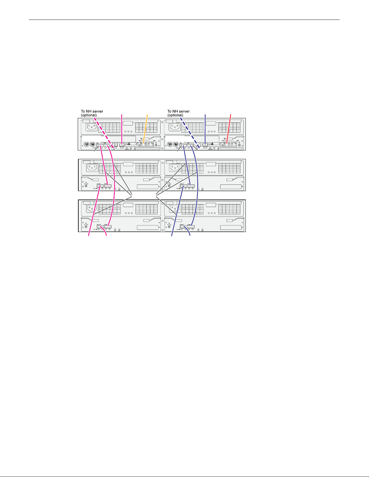
K2 RAID redundant online/production
Primar y
Expansion 1
Expansion 2
DP0DP1
To
Expansion
3
To
Expansion
4
DP0DP1
To
Expansion
3
To
Expansion
4
To K2 Media
Server A
To K2 Media
Server B
To control port
on GigE switch A
To control port
on GigE switch B
Contr oller 1 Contr oller 0
SAS cable connectors are keyed
to DP IN/OUT ports.
SAS cables
NOTE: Do not connect the controller MNT port. It should only be used
with a PC in a peer-to-peer connection for diagnostics purposes.
These cabling instructions apply to the following:
• K2 RAID (Condor with 10G controllers) on a redundant online or production K2 SAN.
Cabling K2 SAN devices
If you have more Expansion chassis than those illustrated, continue the indicated cabling pattern,
alternating connections for additional Expansion chassis between DP1 and DP0. Expansion chassis
1, 3, 5, 7, etc. (odd numbers) connect to DP1. Expansion chassis 2, 4, 6, 8, etc. (even numbers)
connect to DP0. For example, if you have four Expansion chassis (an even number), they are evenly
balanced, so you have two connected to DP1 and two connected to DP0. If you have five Expansion
chassis (an odd number), the “plus one” Expansion chassis is always connected to DP1, so you have
three connected to DP1 and two connected to DP0.
K2 RAID basic nearline
02 February 2012 K2 SAN Installation and Service Manual 59
These cabling instructions apply to the following:
• K2 RAID (Condor with 10G controllers) on a basic nearline K2 SAN.
Page 60

NOTE: Do not connect the controller MNT port. It should only be used
with a PC in a peer-to-peer connection for diagnostics purposes.
Primary
Expansion 1
Expansion 2
DP0DP1
To
Expansion
3
To
Expansion
4
To control port
on GigE switch
To
Server
SAS cable connectors are keyed to DP IN/OUT ports.
SAS cables
Cabling K2 SAN devices
If you have more Expansion chassis than those illustrated, continue the indicated cabling pattern,
alternating connections for additional Expansion chassis between DP1 and DP0. Expansion chassis
1, 3, 5, 7, etc. (odd numbers) connect to DP1. Expansion chassis 2, 4, 6, 8, etc. (even numbers)
connect to DP0. For example, if you have four Expansion chassis (an even number), they are evenly
balanced, so you have two connected to DP1 and two connected to DP0. If you have five Expansion
chassis (an odd number), the “plus one” Expansion chassis is always connected to DP1, so you have
three connected to DP1 and two connected to DP0.
K2 RAID redundant nearline
These cabling instructions apply to the following:
• K2 RAID (Condor with 10G controllers) on a Nearline K2 SAN.
60 K2 SAN Installation and Service Manual 02 February 2012
Page 61

Cabling K2 SAN devices
Continue this cable pattern for additional Expansion Chassis.
02 February 2012 K2 SAN Installation and Service Manual 61
Page 62

Page 63

Chapter 4
Setting up the K2 SAN infrastructure
This section contains the following topics:
• Setting up the Ethernet switch
• Setting up the control point PC
02 February 2012 K2 SAN Installation and Service Manual 63
Page 64

Setting up the K2 SAN infrastructure
Setting up the Ethernet switch
These procedures are for the HP ProCurve switch 2900 and 2910 series. You must use this switch
for iSCSI traffic.
For control and FTP/streaming traffic, it is allowed to use a different brand of switch, such as a
Cisco Catalyst switch, if required by your site. If you are using a non-HP switch, apply the information
in the following procedures accordingly. Refer to the documentation you received with the switch
as necessary.
It is not required that a GigE switch be dedicated to the Nearline system. If enough “control” ports
(non-iSCSI ports) are available on a switch or switches configured for an online K2 SAN, the
Nearline system can be connected to those control ports.
Configuring the Ethernet switch via serial connection
The following procedure is for the HP ProCurve switch 29xx series. Do not use this procedure on
other switch models.
Use a direct console connection to the switch, start a console session, and access the Switch Setup
screen to set the IP address.
1. Configure the PC terminal emulator on the control point PC or another PC as a DEC VT-100
(ANSI) terminal or use a VT-100 terminal, and configure either one to operate with these settings:
• Baud rate 9600
• 8 data bits, 1 stop bit, no parity, and flow control set to Xon/Xoff
• Also disable (uncheck) the “Use Function, Arrow, and Ctrl Keys for Windows” option
2. Connect the PC to the switch’s Console Port using the console cable included with the switch.
If your PC or terminal has a 25-pin serial connector, first attach a 9-pin to 25-pin straight-through
adapter at one end of the console cable.
3. Turn on the PC’s power and start the PC terminal program.
4. Press Enter two or three times and you will see the copyright page and the message “Press any
key to continue”. Press a key, and you will then see the switch console command (CLI) prompt.
NOTE: If you press Enter too many times and get past the log in, enter the command EN to
get into the command line.
5. Type the following, then press Enter:
menu
6. If prompted to save the current configuration, answer no (press the n key) to proceed.
The main menu opens.
7. On the main menu, choose Switch Configuration, then press Enter.
8. Select IP Configuration, then press Enter.
64 K2 SAN Installation and Service Manual 02 February 2012
Page 65

Setting up the K2 SAN infrastructure
9. Press the right-arrow key to choose Edit, then press Enter. Tab to fields and enter information as
follows:
a) Change Gateway to be the default router.
b) Tab to the IP Config (DHCP/Bootp) field and use the Space bar to select the Manual option.
c) Tab to the IP Address field and enter the switch’s control network IP address.
d) Tab to the Subnet Mask field and enter the subnet mask used for your network.
10. Press Enter, then right-arrow to Save. Press Enter and revert to previous menu.
11. Select Return to Main Menu and press Enter.
12. From the main menu, chose Console Passwords and press Enter.
The Set Password Menu opens.
13. Chose Set Manager Password and press Enter.
14. When prompted for the password, type a password of up to 16 ASCII characters with no spaces
and press Enter.
The password can be one that is used on other K2 devices, such as “adminGV!” or “GVAdmin”,
or it can be your site's administrator password.
15. When prompted to enter the password again, retype the password and press Enter.
16. Select Return to Main Menu and press Enter.
17. From the main menu, tab to Command Line (CLI) and press Enter.
The command prompt appears.
18. Type the following, then press Enter:
configure
You are now in configuration mode.
19. Configure an administrator username.
The username can be one that is used on other K2 devices, such as “Administrator” or
“GVAdmin”, or it can be your site's administrator username.
For example, to set the username to “administrator” type the following, then press Enter:
password manager user-name administrator
20. When prompted, enter and re-enter the password.
21. Set spanning tree to RSTP. To do this, type the following, then press Enter:
spanning-tree force-version rstp-operation
This configures spanning tree, but it does not turn spanning tree on. You must turn spanning tree
on using the switch’s Web interface.
22. Decide your SNMP community name as explained in the following options, then proceed with
the next step:
• If you decide to use a unique SNMP community name (not “public”), add the community
and set its RW permissions. For example, if the community name is “K2”, type the following,
then press Enter:
snmp-server community K2 unrestricted
• If you decide to use the default SNMP community “public” for NetCentral monitoring, which
already has RW permissions set as required by NetCentral, proceed to the next step.
02 February 2012 K2 SAN Installation and Service Manual 65
Page 66

Setting up the K2 SAN infrastructure
23. Enter the SNMP community and IP address of the NetCentral server PC. The commands are
slightly different on HP 2900 and HP 2910 switch models.
For example, if the IP address is “192.168.40.11” and the community is “public”, you type one
of the following as per your switch model, then press Enter:
HP 2900: snmp-server host public 192.168.40.11
HP 2910: snmp-server host 192.168.40.11 public
24. Enable Authentication traps. To do this, type the following, then press Enter:
snmp-server enable traps snmp-authentication standard
This allows NetCentral to test the switch to verify that it can send its SNMP trap messages to
NetCentral.
25. Type the following, then press Enter:
menu
When prompted, save the configuration by pressing the y key.
The main menu opens.
26. If you need a trunk for ISLs to gang switches together, use the following steps. These steps
illustrate trunking the last three 1 Gig ports for three 1 Gig ISLs, which is the recommended
configuration for ISLs on all multi-switch K2 SANs. Consult with your Grass Valley representative
if your requirements deviate from the recommended policy:
a) At the main menu, select Switch Configuration and press Enter.
b) Choose selection Port/Trunk Settings and press Enter.
c) Press the right-arrow key to choose Edit, then press Enter.
d) Down arrow until at the bottom of the list of ports and select the last (highest port number)
1 Gig port in the list.
e) Right-arrow over to the Group column.
f) Use the Space bar and set the bottom 1 Gig port to Trk1.
g) Set the next port up also to Trk1.
h) Set the next port up also to Trk1.
i) Press Enter, then right-arrow to Save. Press Enter and revert to previous menu.
27. Select Return to Main Menu and press Enter.
28. From the main menu, tab to Command Line (CLI) and press Enter. The command prompt appears.
29. Check the version of firmware on the switch. To do this, type the following, then press Enter:
show flash
Information is displayed similar to the following example:
HP_iSCSI_switch1# show flash
Image Size(Bytes) Date Version
----- ---------- -------- ------Primary Image : 6737518 07/25/08 T.13.23
Secondary Image : 5886358 10/26/06 T.11.12
Boot Rom Version: K.12.12
Current Boot : Primary
30. Check the Primary Image Version and refer to related topics in "K2 Release Notes" for information
about currently supported versions. If instructed to change the firmware on the switch, do so
before continuing.
66 K2 SAN Installation and Service Manual 02 February 2012
Page 67

31. Type the following, then press Enter:
menu
The main menu opens.
32. From the main menu, choose Reboot Switch and press Enter.
When prompted “Continue Reboot…?', answer yes (press the y key) to proceed.
The switch restarts.
33. You can now use the switch’s web browser interface for further configuration.
34. Close the PC terminal program and disconnect the console cable.
35. if you have multiple switches, repeat this procedure on the other switches.
Next, configure the GigE switch via the Web interface.
Configuring the Ethernet switch via the Web interface
The following procedure is for the HP ProCurve switch 29xx series. Do not use this procedure on
other switch models.
1. From the control point PC or another PC, make sure that you have a direct Ethernet cable
connection to the switch, with no switches, routers, proxies, or other networking devices in
between.
2. On the PC, open Internet Explorer and type the switch’s IP address in the Address field, as in
the following example.
http://192.168.100.61
This should be the name or IP address as currently configured on the switch.
Setting up the K2 SAN infrastructure
3. Press Enter to open the switch’s configuration application.
NOTE: The configuration application for the HP ProCurve switch requires Java.
You can also access the switch’s configuration application from the K2Config application.
02 February 2012 K2 SAN Installation and Service Manual 67
Page 68

Setting up the K2 SAN infrastructure
4. In the switch’s configuration application, choose Configuration, then Device Features.
5. Set Spanning Tree to On and click Apply Changes.
If prompted, log in with the switch’s administrator username and password.
6. Click Port Configuration.
7. Scroll to the bottom of the list and verify that the SFP+ port is port A1.
Re-cable if necessary to correct the SFP+ port.
68 K2 SAN Installation and Service Manual 02 February 2012
Page 69

Setting up the K2 SAN infrastructure
8. If you do not need trunks, such as on a one-switch system, skip to the next step in this procedure.
If you need trunks, such as on a two-switch system with ISLs, do the following:
a) Select (Ctrl + Click) the trunked ports. Typically the trunked ports are at the bottom of the
list and are labeled Trk1.
b) Click Modify Selected Ports.
If prompted, log in as administrator.
c) For the trunked ports, set Port Enabled to Yes. On some switch models, some ports are disabled
by default, so make sure you enable them. Leave Mode as default of Auto.
d) Set Flow Control as follows:
Set to Disable.
e) Click Apply Settings.
9. On the Port Configuration page, do one of the following:
• If you do not have trunks, select all ports.
• If you have trunks, select the remaining ports (the ports not trunked).
02 February 2012 K2 SAN Installation and Service Manual 69
Page 70

Setting up the K2 SAN infrastructure
10. Click Modify Selected Ports.
11. Make sure Port Enabled is set to Yes, leave Mode as default of Auto.
12. Set Flow Control as follows:
Set to Disable.
13. Click Apply Settings.
Wait until settings are applied and the Web interface becomes active.
14. Proceed as follows:
• If the switch carries no media (iSCSI) traffic, such as for a Nearline system, there is no need
to configure VLANs. Skip to the end of this procedure.
• If the switch carries media (iSCSI) traffic, then it must have VLANs configured. Continue
with the next step in this procedure.
70 K2 SAN Installation and Service Manual 02 February 2012
Page 71

Setting up the K2 SAN infrastructure
15. Choose VLAN Configuration.
If prompted, log in with the switch’s administrator username and password.
16. Create a new Media (iSCSI) VLAN as follows:
a) Click Add/Remove VLANs.
b) In the VLAN Name field enter Media.
c) In the VLAN ID field enter 60.
d) Click Add VLAN.
e) If prompted, log in as administrator.
f) Click Main Screen to return to VLAN Configuration.
02 February 2012 K2 SAN Installation and Service Manual 71
Page 72

Setting up the K2 SAN infrastructure
17. Configure the Media VLAN as follows:
a) In the Media VLAN row, click Modify.
b) Select all the odd numbered ports. (Tip: Use Ctrl + Click.)
c) Also select port A1.
This is the 10 Gig SFP+ port on the back of the switch that connects to the K2 Media Server
for media (iSCSI) traffic.
If you have a NH10GE K2 Media Server for FTP traffic, the 10 Gig SFP+ port on the back
of the switch that connects to this server does not go in the Media VLAN. This port stays in
the default VLAN.
d) In the Mode drop-down list, select Untagged, then click Apply. This removes the odd ports
from the default (Control) VLAN.
If you have a trunk, do not configure it as “Tagged”. Media VLAN traffic (iSCSI) does not
go over the trunk.
18. Click the VLAN Configuration tab.
19. If you have a trunk, configure the default (Control) VLAN as follows:
a) In the DEFAULT_VLAN row, click Modify.
b) In the Current Mode list box, scroll down and select the trunk.
c) In the Mode drop-down list, select Tagged, then click Apply. This allows default VLAN traffic
(non-iSCSI) to go over the trunk.
72 K2 SAN Installation and Service Manual 02 February 2012
Page 73

20. Click the VLAN Configuration tab.
Setting up the K2 SAN infrastructure
21. If you have a trunk, verify that for the default VLAN the trunk is displayed in the Tagged Ports
column.
22. If you have two switches, repeat this procedure for the other switch.
23. Close the switch configuration application.
Next, configure QOS on the GigE switch.
Configuring QOS on the GigE switch
Prerequisites for this procedure are as follows:
• The switch is HP ProCurve switch 29xx series.
• Trunks, VLANs and all other configuration is complete.
• The switch has an IP address
• You have network access to the switch
Use this procedure to make the Quality of Service (QOS) setting on the HP ProCurve switch 29xx
series.
1. If you have not already done so, from a network connected PC open the MS-DOS command
prompt and login to the switch as administrator, as follows:
a) Telnet to the switch. For example, if the switch’s IP address is 192.168.40.12, you type the
following, then press Enter.
telnet 192.168.40.12
b) Press Enter one or more times until the switch’s username prompt appears.
c) Type the switch’ s administrator username and press Enter, then type the switch’ s administrator
password and press Enter. The switch console command (CLI) prompt appears.
02 February 2012 K2 SAN Installation and Service Manual 73
Page 74

Setting up the K2 SAN infrastructure
2. Type the following, then press Enter:
config
You are now in configuration mode.
3. Type the following, then press Enter:
qos queue-config 2-queues
This limits the number of active queues within the switch giving the most buffering to VLANs
1 and 60
4. Type the following, then press Enter:
show qos vlan
The screen displays VLAN information. Note the ID number of the Media (iSCSI) VLAN. It
should be 60, as follows:
VLAN priorities
VLAN ID Apply rule | DSCP Priority
------- ----------- + ------ ---------- 1 No-override | No-override
60 No-override | No-override
5. a) Assign the Media VLAN the QOS priority of 3. For example, if the VLAN ID is 60, you type
the following, then press Enter.
vlan 60 qos priority 3
b) Type the following, then press Enter:
show qos vlan
The screen displays VLAN information. Make sure that the Priority column reports that the
Media VLAN has a value of 3.
Next, verify flow control settings.
Verify flow control setting on the GigE switch
Prerequisites for this procedure are as follows:
• The switch is HP ProCurve switch 29xx series.
• Trunks, VLANs, QOS, and all other configuration is complete.
• The switch has an IP address
74 K2 SAN Installation and Service Manual 02 February 2012
Page 75

Setting up the K2 SAN infrastructure
• You have network access to the switch
Use this procedure to check flow control settings, and if necessary, configure flow control to “off”
(disabled) for all ports.
1. If you have not already done so, from a network connected PC open the MS-DOS command
prompt and login to the switch as administrator, as follows:
a) Telnet to the switch. For example, if the switch’s IP address is 192.168.40.12, you type the
following, then press Enter.
telnet 192.168.40.12
b) Press Enter one or more times until the switch’s username prompt appears.
c) Type the switch’ s administrator username and press Enter, then type the switch’ s administrator
password and press Enter. The switch console command (CLI) prompt appears.
2. Type the following, then press Enter:
config
You are now in configuration mode.
3. Type the following, then press Enter:
show interface brief
The screen displays setting for all ports. In the Flow Ctrl column (at the right) identify settings
for ports and proceed as follows:
• If all ports are set to “off”, no further configuration is necessary. Do not proceed.
• If one or more ports are set to “on”, continue with this procedure.
4. Set ports to flow control “off” as necessary. You can set a range of ports. For example, to set
ports 1 - 21 to off, you type the following, then press Enter.
no int 1-21 flow-control
5. Type the following, then press Enter:
show interface brief
Verify that all ports have flow control set to off.
Upgrading firmware on HP switch
1. If you have not already done so, install a TFTP Server.
For example, to install tftpd32.exe, go to http://tftpd32.jounin.net/.
2. Open the TFTP Server.
3. Make sure your current working directory includes the *.swi file that you are using for the
upgrade.
02 February 2012 K2 SAN Installation and Service Manual 75
Page 76

Setting up the K2 SAN infrastructure
4. Execute the copy command with the following syntax:
copy tftp flash <ip-address> <remote-os-file> [ < primary | secondary
> ]
Note that if you do not specify the flash destination, the TFTP download defaults to the primary
flash.
For example, to download a software file named T_13_23.swi from a TFTP server with the IP
address of 10.16.34.3 1, use the following:
ProCurve # copy tftp flash 10.16.34.3 T_13_23.swi
5. When prompted The primary OS image will be deleted. continue [y/n]?, press
Y.
When the switch finishes downloading the software file from the server, it displays the progress
message Validating and Writing System Software to FLASH...
6. Wait until the CLI prompt re-appears, then continue with the next step in this procedure.
7. Check the version of firmware on the switch. To do this, type the following, then press Enter:
show flash
Information is displayed similar to the following example:
HP_iSCSI_switch1# show flash
Image Size(Bytes) Date Version
----- ---------- -------- ------Primary Image : 6737518 07/25/08 T.13.23
Secondary Image : 5886358 10/26/06 T.11.12
Boot Rom Version: K.12.12
Current Boot : Primary
8. Verify that the new software version is in the expected flash area (primary or secondary).
9. Restart the switch from the flash area that holds the new software (primary or secondary).
Setting up the control point PC
To set up the Control Point PC, you have the following options:
• Use the Grass Valley Control Point PC that comes from the factory with software pre-installed.
• Use a PC that you own and install the required software.
1. For either option, you must do the following for the Control Point PC that runs the K2 System
Configuration application:
a) Assign a control network IP address to the PC.
b) Connect the PC to the GigE control network.
2. To use your own PC, you must additionally do the following:
a) Verify that the PC meets system requirements.
b) Install the K2 Control Point software.
c) Install SiteConfig software.
d) Install other supporting software.
e) Install and license NetCentral server software. This can be on the K2 SAN control point PC
or on a separate NetCentral server PC that monitors the K2 SAN.
76 K2 SAN Installation and Service Manual 02 February 2012
Page 77

To fix NetCentral screen resolution problem
To fix the screen resolution problem seen with NetCentral on the Grass Valley Control Point PC,
do the following:
1. Go to Display properties (right mouse selection of properties on the display area)
2. Select Settings tab
3. Select the Advanced button
4. In the General tab, set the DPI setting to Normal size (96 DPI)
5. Restart the PC
Install SiteConfig on control point PC
NOTE: There might be a newer version of this document available. Check your product's release
notes and the Grass Valley website at www.grassvalley.com/docs for references to an updated
version that contains additional important information.
Work through the following topics to install the SiteConfig application on the control point PC.
Setting up the K2 SAN infrastructure
About installing SiteConfig
SiteConfig uses a protocol that involves sending Ethernet broadcast messages to discover and
configure devices. To enable this protocol to work correctly, there must be unrestricted network
access between the PC that hosts SiteConfig and the devices to be discovered.
This is achieved if control network interfaces are all connected to the same switch or to multiple
switches interconnected with ISLs/trunks. If your site requires that other switches and/or routers be
in the network path, you must make sure that no restrictions are in place that block SiteConfig
protocols.
Also, do not install SiteConfig on a PC on which a drive from a managed device is mapped as an
administrative share (C$). For example, if you have a PC set up to run anti-virus software and for
this purpose you have network drives set up on the PC mapped to C$ shares on devices, then do not
use that PC to host SiteConfig and manage those devices.
For a given system, there should be just one instance of SiteConfig managing the system.
System requirements for SiteConfig host PC
The PC on which SiteConfig is installed must meet the following requirements:
Operating system
CommentsRequirements
Microsoft Windows (Must be a U.S. version):
• XP Professional Service Pack 2, Server 2003
• Vista Enterprise Service Pack 1
Minimum 512 MB, 1 GB recommendedRAM
Must have at least 128 MB memoryGraphics acceleration
02 February 2012 K2 SAN Installation and Service Manual 77
Page 78

Setting up the K2 SAN infrastructure
CommentsRequirements
Pentium 4 or higher class, 2 GHz or greaterProcessor
400 MBHard disk space
Version 4.0Microsoft .NET Framework
Java JRE
Installing/upgrading SiteConfig
Prerequisites:
• The PC on which you are installing SiteConfg meets system requirements.
• The PC is connected to the LAN on which all the devices to be managed are connected.
• There are no routed paths to the devices to be managed.
1. Procure SiteConfig installation files from the Grass Valley website or via other distribution
mechanisms.
The following directory and files are required to install SiteConfig:
• DotNetFx directory
• ProductFrameUISetup.msi
• setup.exe
2. If you already have a version of SiteConfig installed, go to Windows Add/Remove Programs and
uninstall it.
3. Double-click setup.exe.
The installation wizard opens.
1.3.1_12 and 1.4.2_05 or higher. Required for
the HP Ethernet Switch configuration interface,
which is used for K2 SANs.
Microsoft XML 4 Service Pack 2 is required.XML
78 K2 SAN Installation and Service Manual 02 February 2012
Page 79

4. Work through the wizard pages, clicking Next and Finish.
Setting up the K2 SAN infrastructure
If the PC does not have the appropriate version of Microsoft .NET, the SiteConfig installation
programs installs it.
5. Open the Windows operating system Services control panel on the PC and look for an entry
called " ProductFrame Discovery Agent".
The Discovery Agent must be installed on the SiteConfig PC so that the PC can be discovered
by SiteConfig and added to the system description as a managed device. This is necessary to
ensure name resolution in SiteConfig's hosts file.
The Discovery Agent is also known as the Network Configuration Connect Kit. For example,
in Windows Add/Remove Programs, it can be displayed as either Network Configuration Connect
Kit or SiteConfig Discovery Agent.
6. Proceed as follows:
• If the Discovery Agent is not installed, navigate to the SiteConfig install location's Discovery
Agent Setup subdirectory and double-click the DiscoveryAgentServiceSetup.msi file. This
launches the setup program and installs the Discovery Agent. Follow the setup wizard to
complete installation. A restart is required after installation. Then continue with the next step
in this procedure.
• If the Discovery Agent is already installed, continue with the next step in this procedure.
7. If not already configured, configure the SiteConfig PC with a valid Ethernet IP address for the
LAN using Windows Network Connections.
8. If you are not going to be using SiteConfig to manage system hosts files, put the system hosts
file on the SiteConfig PC.
02 February 2012 K2 SAN Installation and Service Manual 79
Page 80

Setting up the K2 SAN infrastructure
Install prerequisite files on the SiteConfig PC
Some software components share common prerequisite software. You must install a prerequisite
software package on the SiteConfig PC to make the prerequisite software available for software
deployment to devices.
1. Check release notes for the required version of prerequisite files, if any.
2. On the SiteConfig PC, open Windows Add/Remove programs and look for Grass Valley
Prerequisite Files, then proceed as follows:
• If the required version of prerequisite files is installed, do not proceed with this task.
• If prerequisite files are not installed or are not at the required version, proceed with this task.
3. Procure the required prerequisite software installation file. The file name is Prerequisite
Files.msi.
4. On the SiteConfig PC, run the installation file. The installation program copies prerequisite files
to C:\Program Files\Grass Valley\Prerequisite Files.
80 K2 SAN Installation and Service Manual 02 February 2012
Page 81

Chapter 5
Planning and implementing a K2 SAN with SiteConfig
This section contains the following topics:
• About developing a system description
• Importing a system description
• About device and host names
• Modifying a device name
• Modifying the control network
• Modifying the FTP/streaming network
• Modifying a media (iSCSI) network
• About IP configuration of network interfaces on devices
• Modifying K2 client unassigned (unmanaged) interface
• Modifying K2 Media Server unassigned (unmanaged) interface
• About SiteConfig support on K2 devices
• Discovering devices with SiteConfig
• Assigning discovered devices
• Modifying K2 client managed network interfaces
• Modifying K2 Media Server managed network interfaces
• Making the host name the same as the device name
• Pinging devices from the PC that hosts SiteConfig
• About hosts files and SiteConfig
• Generating host tables using SiteConfig
02 February 2012 K2 SAN Installation and Service Manual 81
Page 82

Planning and implementing a K2 SAN with SiteConfig
About developing a system description
You use SiteConfig to create or modify a system description for the K2 SAN. You can do this in
your planning phase, even before you have devices installed or cabled. Your goal is to have the
SiteConfig system description accurately represent all aspects of your devices and networks before
you begin actually implementing any networking or other configuration tasks.
There are several task flows you can take to develop a system description, as follows:
• Obtain the sales tool system description. This is the system description that was developed for
your specific K2 SAN as part of the sales process. It should be a very accurate representation of
the K2 SAN that is to be installed at the customer site. Import the system description into
SiteConfig and then make final modifications.
• Obtain a similar K2 SAN's system description, import it into SiteConfig, and then modify it until
it matches your K2 SAN.
• In SiteConfig, use the New Site Wizard to create a new system description. The wizard has
models based on the pre-defined K2 SAN levels. You can enter much of your site-specific
information as you work through the wizard, and then do final modifications using other
SiteConfig features.
The topics in this manual follow the task flow for the sales tool system description. If you are using
a different taskflow, use the topics in this manual as appropriate and refer to the SiteConfig User
Manual or SiteConfig Help Topics for additional information.
Importing a system description
Prerequisites for this task are as follows:
• The SiteConfig PC has access to the system description file you are importing.
• Windows Explorer Folder Options must be set to Show hidden files and folders in order to see
all the folders containing SiteConfig files.
1. Open SiteConfig and proceed as follows:
• If a dialog box opens that gives you the choice of creating or importing a system description,
it means SiteConfig does not have access to a system description file. Click Import.
• If the SiteConfig main window opens, click File | Import.
The Import System Description dialog box opens.
2. Browse to and select a system description file (*.scsd) and click Open.
The current system description is closed and the system description you are importing is displayed
in SiteConfig.
82 K2 SAN Installation and Service Manual 02 February 2012
Page 83

About device and host names
In SiteConfig, a device can have different names, as follows:
• Device name — This is a name for display in SiteConfig only. It is stored in the SiteConfig
system description, but not written to the actual device. It is displayed in the device tree view
and in the device list view. It can be a different name than the device’s host name.
• Host name — This is the network name of the device. SiteConfig has a default naming convention
for host names which you can use or override with your own host names.
In most cases it is recommended that the Device name and Host name be the same. This avoids
confusion and aids troubleshooting.
The Device name can serve as a placeholder as a system is planned and implemented. During the
install/commission process, when you reconcile a device's current and planned network interface
settings, the Host name as configured in the system description can be overwritten by the host name
on the actual device. However, the Device name configured in the system description is not affected.
Therefore it is recommended that in the early planned stages, you configure the Device name to be
the desired name for the device, but do not yet configure the Host name. Then, after you have applied
network interface settings, you can change the Host name to be the same as the Device name. This
changes the host name on the actual device so that then all names are in sync.
Planning and implementing a K2 SAN with SiteConfig
SiteConfig does not allow duplicate device names or host names.
Items in the tree view are automatically sorted alphabetically, so if you change a name the item
might sort to a different position.
Modifying a device name
1. In the Network Configuration | Devices tree view, right-click a device and select Rename.
2. Type in the new name.
Note that this does not change the hostname on the physical device. If you want the hostname
to match the device name, you must also modify the hostname.
Modifying the control network
1. In the Network Configuration | Networks tree view, select the K2 SAN's Site node.
The networks under that node are displayed in the list view.
02 February 2012 K2 SAN Installation and Service Manual 83
Page 84

Planning and implementing a K2 SAN with SiteConfig
2. Proceed as follows:
• In the list view, right-click the Control network and select Details.
The Network Settings dialog box opens.
84 K2 SAN Installation and Service Manual 02 February 2012
Page 85

Planning and implementing a K2 SAN with SiteConfig
3. Configure the settings for the network as follows:
For control networkSetting...
Ethernet is requiredType
Control is requiredUsage
Redundancy
Files
Base IP Address
Number of Addresses
Name Suffix
None is required. This is true even on a redundant K2 SAN. (Only the
iSCSI network is redundant on a redundant K2 SAN.)
Control is recommendedName
Unselected is requiredExclude from Host
Selected is requiredManaged
The first (lowest) IP address in the range of IP addresses managed by
SiteConfig. Required.
The number of IP addresses in the range managed by SiteConfig.
Required.
The network's subnet mask. Required.Subnet Mask
Additional network settings managed by SiteConfig. Allowed.Gateway IP Address
Unselected is required. Related settings are disabled.Unmanaged
Servers providing DNS for name resolution. Allowed.DNS Servers
Not allowedDefault Interface
4. Click OK to save settings and close.
Modifying the FTP/streaming network
1. In the Network Configuration | Networks tree view, select the K2 SAN's Site node.
The networks under that node are displayed in the list view.
02 February 2012 K2 SAN Installation and Service Manual 85
Page 86

Planning and implementing a K2 SAN with SiteConfig
2. Proceed as follows:
• In the list view, right-click the Streaming network and select Details.
The Network Settings dialog box opens.
86 K2 SAN Installation and Service Manual 02 February 2012
Page 87

Planning and implementing a K2 SAN with SiteConfig
3. Configure the settings for the network as follows:
For FTP/streaming networkSetting...
Ethernet is requiredType
FileTransfer is requiredUsage
Redundancy
Files
Base IP Address
Number of Addresses
Name Suffix
None is required. This is true even on a redundant K2 SAN. (Only the
iSCSI network is redundant on a redundant K2 SAN.)
Streaming is recommendedName
Unselected is requiredExclude from Host
Selected is requiredManaged
The first (lowest) IP address in the range of IP addresses managed by
SiteConfig. Required.
The number of IP addresses in the range managed by SiteConfig.
Required.
The network's subnet mask. Required.Subnet Mask
Additional network settings managed by SiteConfig. Allowed.Gateway IP Address
Unselected is required. Related settings are disabled.Unmanaged
Servers providing DNS for name resolution. Allowed.DNS Servers
_he0 is requiredDefault Interface
4. Click OK to save settings and close.
Modifying a media (iSCSI) network
1. In the Network Configuration | Networks tree view, select the K2 SAN's Site node.
The networks under that node are displayed in the list view.
02 February 2012 K2 SAN Installation and Service Manual 87
Page 88

Planning and implementing a K2 SAN with SiteConfig
2. Proceed as follows:
• If the K2 SAN is basic (non-redundant), in the list view, right-click the iSCSI network and
select Details.
• If the K2 SAN is redundant, in the list view, first right-click the primary iSCSI network and
select Details. Then proceed to modify the primary iSCSI network. After the primary iSCSI
network is modified, repeat these steps and modify the secondary iSCSI network.
The Network Settings dialog box opens.
88 K2 SAN Installation and Service Manual 02 February 2012
Page 89

Planning and implementing a K2 SAN with SiteConfig
3. Configure the settings for the network as follows:
For media (iSCSI) networkSetting...
Ethernet is requiredType
StorageNetworking is requiredUsage
None is required for a basic (non-redundant) K2 SANRedundancy
Primary is required for a redundant K2 SAN media network A
Secondary is required for a redundant K2 SAN media network B
Name
Files
Base IP Address
Number of Addresses
iSCSI (non-Redundant) is recommended for a basic (non-redundant) K2
SAN
iSCSI (Primary Redundant) is recommended for a redundant K2 SAN
media network A
iSCSI (Secondary Redundant) is recommended for a redundant K2 SAN
media network B
Selected is requiredExclude from Host
Selected is requiredManaged
The first (lowest) IP address in the range of IP addresses managed by
SiteConfig. Required.
The number of IP addresses in the range managed by SiteConfig.
Required.
The network's subnet mask. Required.Subnet Mask
Not allowedGateway IP Address
Unselected is required. Related settings are disabled.Unmanaged
Not allowedDNS Servers
Not allowedDefault Interface
Name Suffix
4. Click OK to save settings and close.
About IP configuration of network interfaces on devices
You can perform IP configuration of network interfaces when working with a placeholder device
prior to discovery. When you add a device and choose a particular model, the model defines the
number, type and usage characteristics of network interfaces to expect on such a device.
You can view and edit each network interface and set up IP configuration selecting an appropriate
IP from the network to which each interface connects. The process for editing IP configuration
varies, depending on the device's phase.
02 February 2012 K2 SAN Installation and Service Manual 89
Page 90

Planning and implementing a K2 SAN with SiteConfig
Placeholder device IP configuration
On a placeholder device, you edit network interfaces using the Unmanaged Network Interfaces
dialog box.
The Unmanaged Network Interfaces dialog box allows you only to save changes to the system
description.
Discovered device IP configuration
On a discovered device, you edit network interfaces using the Managed Network Interfaces dialog
box.
90 K2 SAN Installation and Service Manual 02 February 2012
Page 91

Planning and implementing a K2 SAN with SiteConfig
The Managed Network Interfaces dialog box allows you to edit and save changes to the device.
Modifying K2 client unassigned (unmanaged) interface
Prerequisites for this task are as follows:
• The system description has a SAN K2 client that is a placeholder device.
• The placeholder device has a one or more unmanaged network interfaces.
Use this task to modify unmanaged network interfaces on a K2 SAN device as follows:
• K2 Summit Production Client
1. In the Network Configuration | Devices tree view, select a SAN K2 client placeholder device.
The interfaces for that device are displayed in the interfaces list view.
02 February 2012 K2 SAN Installation and Service Manual 91
Page 92

Planning and implementing a K2 SAN with SiteConfig
2. In the interfaces list view, right-click an interface and select Edit.
The Unmanaged Network Interface Details dialog box opens.
92 K2 SAN Installation and Service Manual 02 February 2012
Page 93

Planning and implementing a K2 SAN with SiteConfig
3. Configure the settings for the interface as follows:
For control network interfaceSetting...
Control is requiredNetwork
The IP address for this interface on the network. Required.IP Address
The device host name. Required.Interface Name
Set to Default
...use Interface
Name/Aliases in
Host Files...
DNS Suffix
Network
Not recommended. Sets the interface name to SiteConfig default convention,
based on the root Site name and device-type.
Unselected is required. Since not selected, the default behavior occurs, which
is to use the device host name in the hosts file.
Not allowedAliases
Allowed, if applicable to the network. The DNS suffix is added to the
interface name.
For media (iSCSI) network interfaceSetting...
iSCSI (non-Redundant) is required for one iSCSI interface on a K2 client
on a basic K2 SAN. The other iSCSI interface is unused.
iSCSI (Primary Redundant) is required for one iSCSI interface on a K2
client on a redundant K2 SAN.
iSCSI (Secondary Redundant) is required for the other iSCSI interface on a
K2 client on a redundant K2 SAN
The IP address for this interface on the network. Required.IP Address
Disabled, since names are excluded from the hosts file. Disregard.Interface Name
Disabled, since names are excluded from the hosts file. Disregard.Set to Default
Disabled, since names are excluded from the hosts file. Disregard....use Interface
Name/Aliases in
Host Files...
Disabled, since names are excluded from the hosts file. Disregard.Aliases
Disabled, since names are excluded from the hosts file. Disregard.DNS Suffix
NOTE: There is no FTP/streaming network for a SAN K2 client. On the K2 SAN,
FTP/streaming goes to the K2 Media Server.
4. Click OK to save settings and close.
Modifying K2 Media Server unassigned (unmanaged) interface
Prerequisites for this task are as follows:
• The system description has a K2 Media Server that is a placeholder device.
02 February 2012 K2 SAN Installation and Service Manual 93
Page 94

Planning and implementing a K2 SAN with SiteConfig
• The placeholder device has a one or more unmanaged network interfaces.
Use this task to modify managed network interfaces on a K2 SAN device as follows:
• 10G K2 Media Server
• NH K2 Media Server
For the K2 Media Server, do not configure the Fibre Channel interface. SiteConfig does not manage
this interface. It is represented in SiteConfig only to complete the description of the K2 Media
Server.
1. In the Network Configuration | Devices tree view, select a K2 Media Server placeholder device.
The interfaces for that device are displayed in the interfaces list view.
2. In the interfaces list view, right-click an interface and select Edit.
The Unmanaged Network Interface Details dialog box opens.
94 K2 SAN Installation and Service Manual 02 February 2012
Page 95

Planning and implementing a K2 SAN with SiteConfig
3. Configure the settings for the interface as follows:
For control network interfaceSetting...
Control is requiredNetwork
The IP address for this interface on the network. Required.IP Address
The device host name. Required.Interface Name
Set to Default
...use Interface
Name/Aliases in
Host Files...
DNS Suffix
Interface Name
Set to Default
Name/Aliases in
Host Files...
Not recommended. Sets the interface name to SiteConfig default convention,
based on the root Site name and device-type.
Unselected is required. Since not selected, the default behavior occurs, which
is to use the device host name in the hosts file.
Not allowedAliases
Allowed, if applicable to the network. The DNS suffix is added to the
interface name.
For FTP/streaming network interfaceSetting...
Streaming is requiredNetwork
The IP address for this interface on the network. Required.IP Address
The device host name with the " _he0" suffix added is required. For example,
if the host name is K2prod01, then K2prod01_he0 is required here.
Not recommended. Sets the interface name to SiteConfig default convention,
based on the root Site name and device-type.
Selected is required...use Interface
Not allowedAliases
DNS Suffix
Allowed, if applicable to the network. The DNS suffix is added to the
interface name.
For media (iSCSI) network interfaceSetting...
Network
iSCSI (non-Redundant) is required on K2 Media Server for all interfaces of
type iSCSI on basic K2 SAN.
iSCSI (Primary Redundant) is required on K2 Media Server A for all
interfaces of type iSCSI on redundant K2 SAN
iSCSI (Secondary Redundant) is required on K2 Media Server B for interfaces
of type iSCSI on redundant K2 SAN
The IP address for this interface on the network. Required.IP Address
Disabled, since names are excluded from the hosts file. Disregard.Interface Name
02 February 2012 K2 SAN Installation and Service Manual 95
Page 96

Planning and implementing a K2 SAN with SiteConfig
For media (iSCSI) network interfaceSetting...
Disabled, since names are excluded from the hosts file. Disregard.Set to Default
Disabled, since names are excluded from the hosts file. Disregard....use Interface
Name/Aliases in
Host Files...
Disabled, since names are excluded from the hosts file. Disregard.Aliases
Disabled, since names are excluded from the hosts file. Disregard.DNS Suffix
4. Click OK to save settings and close.
About SiteConfig support on K2 devices
Before SiteConfig can be used to discover or manage a device, the device must meet the following
requirements:
• The device must be a Microsoft Windows operating system device.
• The device must have Microsoft .NET version 2.0 installed, as reported in the Windows
Add/Remove Programs control panel.
• The SiteConfig Discovery Agent service must be running on the device, as reported in the
Windows Services control panel.
For K2 clients and K2 Media Servers shipped new from Grass Valley with K2 software version 7.0
or higher, these requirements are pre-installed. These requirements are pre-installed on recovery
images for these K2 systems as well. Therefore, if you suspect a problem with these requirements,
do not attempt to install SiteConfig support requirements. If you must restore SiteConfig support
requirements, re-image the K2 system.
Discovering devices with SiteConfig
Prerequisites for this task are as follows:
• The Ethernet switch or switches that support the control network are configured and operational.
If multiple switches, ISLs are connected and trunks configured.
• The PC that hosts SiteConfig is communicating on the control network.
• There are no routers between the PC that hosts SiteConfig and the devices to be discovered.
• Devices to be discovered are Windows operating system devices, with SiteConfig support
installed.
• Devices are cabled for control network connections.
• If discovering a device with Microsoft Windows Server 2008 operating system, the device must
have an IP address, either static or DHCP supplied.
1. Open SiteConfig.
96 K2 SAN Installation and Service Manual 02 February 2012
Page 97

Planning and implementing a K2 SAN with SiteConfig
2. In the toolbar, click the discover devices button.
The Discover Devices dialog box opens.
A list of discovered devices is displayed.
3. Click Rescan to re-run the discovery mechanism. You can do this if a device that you want to
discover has its network connection restored or otherwise becomes available. Additional devices
discovered are added to the list.
Assigning discovered devices
Prerequisites for this task are as follows:
• Devices have been discovered by SiteConfig
• Discovered devices are not yet assigned to a device in the system description
• The system description has placeholder devices to which to assign the discovered devices.
1. If the Discovered Devices Dialog box is not already open, click the discover devices button .
The Discover Devices dialog box opens.
2. Identify discovered devices.
• If a single device is discovered in multiple rows, it means the device has multiple network
interfaces. Choose the interface that represents the device's currently connected control
connection. This is typically Ethernet ... 0.
• If necessary, select a device in the list and click ID Device. This triggers an action on the
device, such as flashing an LED or ejecting a CD drive, to identify the device.
02 February 2012 K2 SAN Installation and Service Manual 97
Page 98

Planning and implementing a K2 SAN with SiteConfig
3. To also view previously discovered devices that have already been assigned to a device in the
system description, select Show … currently assigned devices.
The currently assigned devices are added to the list. Viewing both assigned and unassigned
devices in this way can be helpful to verify the match between discovered devices and placeholder
devices.
4. In the row for each discovered device, view items on the Device Id drop-down list to determine
the match with placeholder devices, as follows:
• If SiteConfig finds a match between the device-type discovered and the device-type of one
or more placeholder devices, it displays those placeholder devices in the list.
• If SiteConfig does not find a match between the device-type discovered and the device-type
of a placeholder device, no placeholder device is displayed in the list.
5. In the row for a discovered device, click the Device Id drop-down list and select the placeholder
device that corresponds to the discovered device.
If there is no corresponding placeholder device currently in the system description, you can select
Add to create a new placeholder device and then assign the discovered device to it.
6. When discovered devices have been assigned, click OK to save settings and close.
7. In the Network Configuration | Devices tree view, select each of the devices to which you assigned
a discovered device.
Modifying K2 client managed network interfaces
Prerequisites for this task are as follows:
• The physical device you are configuring has been discovered and is assigned to a device in the
SiteConfig system description.
• SiteConfig has communication with the device.
• The device is defined in the system description with an appropriate network interface.
Use this task to modify managed network interfaces on a K2 SAN device as follows:
• K2 Summit Production Client
1. In the tree view select a K2 client, then in the Interfaces list view, identify interfaces as follows:
• The SAN K2 client's control interface is a team. Modify the control team interface first. The
control team is comprised of two individual interfaces, one for Control Connection #1 and
one for Control Connection # 2. Do not modify these two individual interfaces.
• For a SAN K2 client on a basic (non-redundant) K2 SAN, identify the iSCSI (non-Redundant)
interface. After the control team, modify this interface as instructed in this procedure. Do not
configure any other iSCSI interface, as only one iSCSI interface is used for a basic K2 SAN.
• For a SAN K2 client on a redundant K2 SAN, identify the iSCSI (Primary Redundant) interface
and the iSCSI (Primary Secondary) interface. After the control team, modify these interfaces
as instructed in this procedure.
• The SAN K2 client has no interface for FTP/streaming. All FTP/streaming goes to the K2
Media Server.
98 K2 SAN Installation and Service Manual 02 February 2012
Page 99

Planning and implementing a K2 SAN with SiteConfig
2. In the Interfaces list view determine the interface to configure, as follows:
• Identify the interface with which SiteConfig is currently communicating, indicated by the
green star overlay icon. This should be the control network interface.
• Verify that the interface over which SiteConfig is currently communicating is in fact the
interface defined for the control network in the system description. If this is not the case, you
might have the control network cable connected to the wrong interface port. The control
connection should always be the first port on the motherboard, except when you have a
loopback connection.
• Configure the control network interface first before configuring any of the other interfaces.
• After you have successfully configured the control network interface, return to this step to
configure each remaining interface.
3. In the Interfaces list view, check the icon for the interface you are configuring.
If the icon has a red stop sign overlay, it indicates that current settings and planned settings do
not match or that there is some other problem. Hover over the icon to read a tooltip with
information about the problem.
NOTE: For the K2 Summit Production Client, make sure that the device is unlocked in
SiteConfig before proceeding. This disables the write filter.
02 February 2012 K2 SAN Installation and Service Manual 99
Page 100

Planning and implementing a K2 SAN with SiteConfig
4. In the Interfaces list view, right-click the interface you are configuring and select Edit.
The Managed Network Interface Details dialog box opens.
5. Identify the interface on the discovered device that you are configuring.
• Identify Ethernet LAN adapters by their "Description" name. This is the Windows connection
name. SiteConfig reads this name from the device and displays it at the top of this dialog box.
This is the most accurate way to identify the network adapter on the discovered device that
you are configuring.
100 K2 SAN Installation and Service Manual 02 February 2012
 Loading...