

Page 1
Jupiter
Control System
L-S Series Control Panels
Installation and Operating Manual
SOFTWARE VERSION 1.0
071853600
NOVEMBER 2008
Page 2

Affiliate with the N.V. KEMA in The Netherlands
CERTIFICATE
Certificate Number: 510040.001
The Quality System of:
Grass Valley, Inc.
400 Providence Mine Road
Nevada City, CA 95945
United States
15655 SW Greystone Ct.
Beaverton, OR 97006
United States
10 Presidential Way
3
rd
Floor, Suite 300
Woburn, MA 01801
United States
Nederland B.V.
4800 RP BREDA
The Netherlands
Weiterstadt, Germany
Brunnenweg 9
D-64331 Weiterstadt
Germany
Rennes, France
Rue du Clos Courtel
Cesson-Sevigne, Cedex
France
Technopole Brest Iroise
CS 73808
29238 Brest Cedex 3
France
17 rue du Petit Albi-BP 8244
95801 Cergy Pontoise
Cergy, France
2300 South Decker Lake Blvd.
Salt Lake City, UT 84119
United States
7140 Baymeadows Way
Suite 101
Jacksonville, FL 32256
United States
Including its implementation, meets the requirements of the standard:
ISO 9001:2000
Scope:
The design, manufacture and support of video hardware and software products and
related systems.
This Certificate is valid until: June 14, 2009
This Certificate is valid as of: August 30, 2006
Certified for the first time: June 14, 2000
H. Pierre Sallé
President
KEMA-Registered Quality
The method of operation for quality certification is defined in the KEMA General Terms
And Conditions For Quality And Environmental Management Systems Certifications.
Integral publication of this certificate is allowed.
KEMA-Registered Quality, Inc.
4377 County Line Road
Chalfont, PA 18914
Ph: (215)997-4519
Fax: (215)997-3809
CRT 001 073004
ccredited By:
ANAB
A
Page 3
Jupiter
Control System
L-S Series Control Panels
Installation and Operating Manual
SOFTWARE VERSION 1.0
071853600
NOVEMBER 2008
Page 4
Contacting Grass Valley
International
Support Centers
Local Support
Centers
ailable
(av
during normal
business hours)
France
24 x 7
Australia and New Zealand: +6
Middle East: +9
Europe
+800 8080 2020 or +33 1 48 25 20 20
+800 8080 2020 or +33 1 48 25 20 20
Hong Kong, Taiwan, Korea, Macau: +8
Asia
Southeast Asia/Malaysia: +6
China: +8
Belarus, Russia, Tadzikistan, Ukraine,
S. Europe/Italy-Roma: +3
Benelux/Belgium: +3
Germany, Austria, Eastern Europe: +4
61 0660 159 450 Japan: +81 3 5484 6868
71 4 299 64 40 Near East and Africa: +800 8080 2020 or +33 1 48 25 20 20
Copyright © Thomson. All rights reserved.
This product may be covered by one or more U.S. and foreign patents.
Grass Valley Web Site
The www.thomsongrassvalley.com web site offers the following:
Online User Documentation — Current versions of product catalogs, brochures,
data sheets, ordering guides, planning guides, manuals, and release notes
in.pdf format can be downloaded.
FAQ Database — Solutions to problems and troubleshooting efforts can be
found by searching our Frequently Asked Questions (FAQ) database.
United States/Canada
24 x 7
52 2531 3058 Indian Subcontinent: +91 22 24933476
03 7805 3884 Southeast Asia/Singapore: +65 6379 1313
1 1300 721 495 Central/South America: +55 11 5509 3443
Uzbekistan: +7 095 2580924 225 Switzerland: +41 1 487 80 02
9 06 87 20 35 28 -Milan: +39 02 48 41 46 58 S. Europe/Spain: +34 91 512 03 50
2 (0) 2 334 90 30 Benelux/Netherlands: +31 (0) 35 62 38 42 1 N. Europe: +45 45 96 88 70
9 6150 104 444 UK, Ireland, Israel: +44 118 923 0499
+1 800 547 8949 or +1 530 478 4148
Software Downloads — Download software updates, drivers, and patches.
4 Jupiter L-S Series Control Panels Installation and Operating Manual
Page 5

Contents
Preface. . . . . . . . . . . . . . . . . . . . . . . . . . . . . . . . . . . . . . . . . . . . . . . . . . . . . . . . . . . . . . . . . . . . 11
Safety Summary
Regulatory Notices
About This Manual . . . . . . . . . . . . . . . . . . . . . . . . . . . . . . . . . . . . . . . . . . . . . . . . . . . . 11
Additional Documentation . . . . . . . . . . . . . . . . . . . . . . . . . . . . . . . . . . . . . . . . . . . 11
Safety Terms and Symbols. . . . . . . . . . . . . . . . . . . . . . . . . . . . . . . . . . . . . . . . . . . . . . 13
Terms in This Manual . . . . . . . . . . . . . . . . . . . . . . . . . . . . . . . . . . . . . . . . . . . . . . . . 13
Terms on the Product . . . . . . . . . . . . . . . . . . . . . . . . . . . . . . . . . . . . . . . . . . . . . . . . 13
Symbols on the Product . . . . . . . . . . . . . . . . . . . . . . . . . . . . . . . . . . . . . . . . . . . . . . 14
Warnings . . . . . . . . . . . . . . . . . . . . . . . . . . . . . . . . . . . . . . . . . . . . . . . . . . . . . . . . . . . . 14
Cautions . . . . . . . . . . . . . . . . . . . . . . . . . . . . . . . . . . . . . . . . . . . . . . . . . . . . . . . . . . . . . 15
Certifications and Compliances . . . . . . . . . . . . . . . . . . . . . . . . . . . . . . . . . . . . . . . . . 17
FCC Emission Control . . . . . . . . . . . . . . . . . . . . . . . . . . . . . . . . . . . . . . . . . . . . . . . 17
Canadian EMC Notice of Compliance . . . . . . . . . . . . . . . . . . . . . . . . . . . . . . . . . . 17
EN55022 Class A Warning . . . . . . . . . . . . . . . . . . . . . . . . . . . . . . . . . . . . . . . . . . . . 17
Canadian Certified Power Cords . . . . . . . . . . . . . . . . . . . . . . . . . . . . . . . . . . . . . . 18
Canadian Certified AC Adapter . . . . . . . . . . . . . . . . . . . . . . . . . . . . . . . . . . . . . . . 18
Safety and EMI Certification . . . . . . . . . . . . . . . . . . . . . . . . . . . . . . . . . . . . . . . . . . 18
Section 1 — Introduction. . . . . . . . . . . . . . . . . . . . . . . . . . . . . . . . . . . . . . . . . . . . . . . . 21
Overview . . . . . . . . . . . . . . . . . . . . . . . . . . . . . . . . . . . . . . . . . . . . . . . . . . . . . . . . . . . . 21
L Series Control Panel Features . . . . . . . . . . . . . . . . . . . . . . . . . . . . . . . . . . . . . . . . . 22
L32 . . . . . . . . . . . . . . . . . . . . . . . . . . . . . . . . . . . . . . . . . . . . . . . . . . . . . . . . . . . . . . . . 22
L64 . . . . . . . . . . . . . . . . . . . . . . . . . . . . . . . . . . . . . . . . . . . . . . . . . . . . . . . . . . . . . . . . 22
LD4. . . . . . . . . . . . . . . . . . . . . . . . . . . . . . . . . . . . . . . . . . . . . . . . . . . . . . . . . . . . . . . . 23
LD16. . . . . . . . . . . . . . . . . . . . . . . . . . . . . . . . . . . . . . . . . . . . . . . . . . . . . . . . . . . . . . . 24
S Series Control Panel Features. . . . . . . . . . . . . . . . . . . . . . . . . . . . . . . . . . . . . . . . . . 25
S25/S50 . . . . . . . . . . . . . . . . . . . . . . . . . . . . . . . . . . . . . . . . . . . . . . . . . . . . . . . . . . . . 25
S100 . . . . . . . . . . . . . . . . . . . . . . . . . . . . . . . . . . . . . . . . . . . . . . . . . . . . . . . . . . . . . . . 26
SXY. . . . . . . . . . . . . . . . . . . . . . . . . . . . . . . . . . . . . . . . . . . . . . . . . . . . . . . . . . . . . . . . 27
Specifications . . . . . . . . . . . . . . . . . . . . . . . . . . . . . . . . . . . . . . . . . . . . . . . . . . . . . . . . . 27
Ordering Information. . . . . . . . . . . . . . . . . . . . . . . . . . . . . . . . . . . . . . . . . . . . . . . . . . 28
Section 2 — Hardware Installation. . . . . . . . . . . . . . . . . . . . . . . . . . . . . . . . . . . . . 31
Rack Mounting . . . . . . . . . . . . . . . . . . . . . . . . . . . . . . . . . . . . . . . . . . . . . . . . . . . . . . . 31
Power Supplies . . . . . . . . . . . . . . . . . . . . . . . . . . . . . . . . . . . . . . . . . . . . . . . . . . . . . . . 31
Network Wiring . . . . . . . . . . . . . . . . . . . . . . . . . . . . . . . . . . . . . . . . . . . . . . . . . . . . . . 33
Button Labels . . . . . . . . . . . . . . . . . . . . . . . . . . . . . . . . . . . . . . . . . . . . . . . . . . . . . . . . . 33
L32/L64/S100 Panels . . . . . . . . . . . . . . . . . . . . . . . . . . . . . . . . . . . . . . . . . . . . . . . . 34
LD4 Panels . . . . . . . . . . . . . . . . . . . . . . . . . . . . . . . . . . . . . . . . . . . . . . . . . . . . . . . . . 34
LD16 Panels . . . . . . . . . . . . . . . . . . . . . . . . . . . . . . . . . . . . . . . . . . . . . . . . . . . . . . . . 35
S25/S50 . . . . . . . . . . . . . . . . . . . . . . . . . . . . . . . . . . . . . . . . . . . . . . . . . . . . . . . . . . . . 35
Jupiter L-S Series Control Panels Installation and Operating Manual 5
Page 6

Contents
SXY Panels . . . . . . . . . . . . . . . . . . . . . . . . . . . . . . . . . . . . . . . . . . . . . . . . . . . . . . . . . 35
Button Configuration Overview. . . . . . . . . . . . . . . . . . . . . . . . . . . . . . . . . . . . . . . 36
Source Button Configuration. . . . . . . . . . . . . . . . . . . . . . . . . . . . . . . . . . . . . . . . 36
Category Button Configuration . . . . . . . . . . . . . . . . . . . . . . . . . . . . . . . . . . . . . 36
Level Button Configuration. . . . . . . . . . . . . . . . . . . . . . . . . . . . . . . . . . . . . . . . . 36
Keycap Transparency Labels . . . . . . . . . . . . . . . . . . . . . . . . . . . . . . . . . . . . . . . . . 36
Section 3 — Software Installation & IP Addresses . . . . . . . . . . . . . . . . . . . 39
Introduction. . . . . . . . . . . . . . . . . . . . . . . . . . . . . . . . . . . . . . . . . . . . . . . . . . . . . . . . . . 39
Software Installation . . . . . . . . . . . . . . . . . . . . . . . . . . . . . . . . . . . . . . . . . . . . . . . . . . 40
NetConfig Installation . . . . . . . . . . . . . . . . . . . . . . . . . . . . . . . . . . . . . . . . . . . . . . . 40
L-S Panels Installation (on Jupiter File Server). . . . . . . . . . . . . . . . . . . . . . . . . . . 42
Network IP Addresses. . . . . . . . . . . . . . . . . . . . . . . . . . . . . . . . . . . . . . . . . . . . . . . . . 43
Single Network IP Configuration. . . . . . . . . . . . . . . . . . . . . . . . . . . . . . . . . . . . . . 43
Multi-Network IP Configuration . . . . . . . . . . . . . . . . . . . . . . . . . . . . . . . . . . . . . . 44
Network Configuration Procedure (NetConfig) . . . . . . . . . . . . . . . . . . . . . . . . . 44
Setting IP Addresses on L-S Panels . . . . . . . . . . . . . . . . . . . . . . . . . . . . . . . . . . . . 45
Setting Jupiter Values for L-S Panels . . . . . . . . . . . . . . . . . . . . . . . . . . . . . . . . . . . 46
Finding the Physical Location of a Panel . . . . . . . . . . . . . . . . . . . . . . . . . . . . . . . . . 47
L-S Panel Software Update . . . . . . . . . . . . . . . . . . . . . . . . . . . . . . . . . . . . . . . . . . . . . 47
Section 4 — Jupiter System Configuration . . . . . . . . . . . . . . . . . . . . . . . . . . . . 49
MPK Table Entries . . . . . . . . . . . . . . . . . . . . . . . . . . . . . . . . . . . . . . . . . . . . . . . . . . . . 49
Control Panel Sets . . . . . . . . . . . . . . . . . . . . . . . . . . . . . . . . . . . . . . . . . . . . . . . . . . . . 51
CP Level Set. . . . . . . . . . . . . . . . . . . . . . . . . . . . . . . . . . . . . . . . . . . . . . . . . . . . . . . . 51
CP Input and CP Output Sets . . . . . . . . . . . . . . . . . . . . . . . . . . . . . . . . . . . . . . . . . 51
Sequence Set . . . . . . . . . . . . . . . . . . . . . . . . . . . . . . . . . . . . . . . . . . . . . . . . . . . . . . . 52
Setting Up a Salvo with a Sequence Set. . . . . . . . . . . . . . . . . . . . . . . . . . . . . . . 52
Compiling . . . . . . . . . . . . . . . . . . . . . . . . . . . . . . . . . . . . . . . . . . . . . . . . . . . . . . . . . . . 53
Section 5 — L-S Series Panel Operation . . . . . . . . . . . . . . . . . . . . . . . . . . . . . . 55
Introduction. . . . . . . . . . . . . . . . . . . . . . . . . . . . . . . . . . . . . . . . . . . . . . . . . . . . . . . . . . 55
Section Contents . . . . . . . . . . . . . . . . . . . . . . . . . . . . . . . . . . . . . . . . . . . . . . . . . . . . 55
Color Bitmap Displays . . . . . . . . . . . . . . . . . . . . . . . . . . . . . . . . . . . . . . . . . . . . . . . 55
Destination/Status . . . . . . . . . . . . . . . . . . . . . . . . . . . . . . . . . . . . . . . . . . . . . . . . 55
Preset/Level. . . . . . . . . . . . . . . . . . . . . . . . . . . . . . . . . . . . . . . . . . . . . . . . . . . . . . 56
D1 - D16 . . . . . . . . . . . . . . . . . . . . . . . . . . . . . . . . . . . . . . . . . . . . . . . . . . . . . . . . . 56
Use of Color . . . . . . . . . . . . . . . . . . . . . . . . . . . . . . . . . . . . . . . . . . . . . . . . . . . . . . . . 56
Basic Panel Operations. . . . . . . . . . . . . . . . . . . . . . . . . . . . . . . . . . . . . . . . . . . . . . . 56
Taking a Source to a Destination (Take) . . . . . . . . . . . . . . . . . . . . . . . . . . . . . . 56
Destination Protection . . . . . . . . . . . . . . . . . . . . . . . . . . . . . . . . . . . . . . . . . . . . . 57
Destination Locking . . . . . . . . . . . . . . . . . . . . . . . . . . . . . . . . . . . . . . . . . . . . . . . 57
Breakaway . . . . . . . . . . . . . . . . . . . . . . . . . . . . . . . . . . . . . . . . . . . . . . . . . . . . . . . 57
Sticky Levels Mode . . . . . . . . . . . . . . . . . . . . . . . . . . . . . . . . . . . . . . . . . . . . . . . . 57
Sequences (Salvos) . . . . . . . . . . . . . . . . . . . . . . . . . . . . . . . . . . . . . . . . . . . . . . . . 57
Source Swap Mode . . . . . . . . . . . . . . . . . . . . . . . . . . . . . . . . . . . . . . . . . . . . . . . . 57
Preset Mode - L32, L64, S100 . . . . . . . . . . . . . . . . . . . . . . . . . . . . . . . . . . . . . . . . 57
Assignable Buttons - L32, L64, S100. . . . . . . . . . . . . . . . . . . . . . . . . . . . . . . . . . 58
L32/L64 Control Panels . . . . . . . . . . . . . . . . . . . . . . . . . . . . . . . . . . . . . . . . . . . . . . . 59
L32 and L64 Panel Differences . . . . . . . . . . . . . . . . . . . . . . . . . . . . . . . . . . . . . . . . 59
Show Button Assignment . . . . . . . . . . . . . . . . . . . . . . . . . . . . . . . . . . . . . . . . . . . . 59
6 Jupiter L-S Series Control Panels Installation and Operating Manual
Page 7

Contents
Clearing Panel Modes. . . . . . . . . . . . . . . . . . . . . . . . . . . . . . . . . . . . . . . . . . . . . . . . 60
Destination and Source Selection Methods . . . . . . . . . . . . . . . . . . . . . . . . . . . . . . 60
Selecting a Destination to be Controlled . . . . . . . . . . . . . . . . . . . . . . . . . . . . . . . . 60
Direct Selection Method . . . . . . . . . . . . . . . . . . . . . . . . . . . . . . . . . . . . . . . . . . . . 60
Menu Selection Method . . . . . . . . . . . . . . . . . . . . . . . . . . . . . . . . . . . . . . . . . . . . 61
Selecting a Source . . . . . . . . . . . . . . . . . . . . . . . . . . . . . . . . . . . . . . . . . . . . . . . . . . . 61
Direct Selection Method . . . . . . . . . . . . . . . . . . . . . . . . . . . . . . . . . . . . . . . . . . . . 61
Direct Selection with Preset . . . . . . . . . . . . . . . . . . . . . . . . . . . . . . . . . . . . . . . . . 61
Menu Selection Method . . . . . . . . . . . . . . . . . . . . . . . . . . . . . . . . . . . . . . . . . . . . 62
Protecting a Destination . . . . . . . . . . . . . . . . . . . . . . . . . . . . . . . . . . . . . . . . . . . . . . 62
Locking a Destination . . . . . . . . . . . . . . . . . . . . . . . . . . . . . . . . . . . . . . . . . . . . . . . . 63
Breakaway Switching . . . . . . . . . . . . . . . . . . . . . . . . . . . . . . . . . . . . . . . . . . . . . . . . 63
Direct Selection Breakaway . . . . . . . . . . . . . . . . . . . . . . . . . . . . . . . . . . . . . . . . . 64
Menu Breakaway Method . . . . . . . . . . . . . . . . . . . . . . . . . . . . . . . . . . . . . . . . . . 64
Breakaway Source Status . . . . . . . . . . . . . . . . . . . . . . . . . . . . . . . . . . . . . . . . . . . 65
Sticky Levels Mode . . . . . . . . . . . . . . . . . . . . . . . . . . . . . . . . . . . . . . . . . . . . . . . . 65
Executing a Sequence (Salvo) . . . . . . . . . . . . . . . . . . . . . . . . . . . . . . . . . . . . . . . . . 65
Direct Execution. . . . . . . . . . . . . . . . . . . . . . . . . . . . . . . . . . . . . . . . . . . . . . . . . . . 65
Direct Execution with Preset . . . . . . . . . . . . . . . . . . . . . . . . . . . . . . . . . . . . . . . . 66
Menu Execution . . . . . . . . . . . . . . . . . . . . . . . . . . . . . . . . . . . . . . . . . . . . . . . . . . . 66
Source Swap Mode . . . . . . . . . . . . . . . . . . . . . . . . . . . . . . . . . . . . . . . . . . . . . . . . . . 66
Button Assignment . . . . . . . . . . . . . . . . . . . . . . . . . . . . . . . . . . . . . . . . . . . . . . . . . . 67
Undo (L64 Only) . . . . . . . . . . . . . . . . . . . . . . . . . . . . . . . . . . . . . . . . . . . . . . . . . . . . 67
Front-Panel Service Modes. . . . . . . . . . . . . . . . . . . . . . . . . . . . . . . . . . . . . . . . . . . . 68
LD4 Control Panel. . . . . . . . . . . . . . . . . . . . . . . . . . . . . . . . . . . . . . . . . . . . . . . . . . . . . 69
LD4 Operating Modes . . . . . . . . . . . . . . . . . . . . . . . . . . . . . . . . . . . . . . . . . . . . . . . 69
LD4 Single Destination Mode . . . . . . . . . . . . . . . . . . . . . . . . . . . . . . . . . . . . . . . . . 69
Entering Single Destination Mode . . . . . . . . . . . . . . . . . . . . . . . . . . . . . . . . . . . 69
Selecting a Destination to be Controlled (Single Destination Mode) . . . . . . . 70
Selecting a Source (Single Destination Mode) . . . . . . . . . . . . . . . . . . . . . . . . . . 70
Breakaways (LD4 Panel). . . . . . . . . . . . . . . . . . . . . . . . . . . . . . . . . . . . . . . . . . . . 71
Sticky Levels Mode (LD4 Panel) . . . . . . . . . . . . . . . . . . . . . . . . . . . . . . . . . . . . . 73
LD4 Multiple Destination Mode . . . . . . . . . . . . . . . . . . . . . . . . . . . . . . . . . . . . . . . 73
Entering Multiple Destination Mode . . . . . . . . . . . . . . . . . . . . . . . . . . . . . . . . . 73
Selecting a Destination to Control (Multiple Destination Mode) . . . . . . . . . . 74
Selecting a Source (Multiple Destination Mode). . . . . . . . . . . . . . . . . . . . . . . . 74
Adding or Changing a Destination Soft Button Assignment . . . . . . . . . . . . . 74
Protecting or Locking a Destination . . . . . . . . . . . . . . . . . . . . . . . . . . . . . . . . . . . . 75
Unprotecting or Unlocking a Destination . . . . . . . . . . . . . . . . . . . . . . . . . . . . . 75
Source Swap Mode (LD4 Panel) . . . . . . . . . . . . . . . . . . . . . . . . . . . . . . . . . . . . . . . 76
Overrides (LD4 Panel) . . . . . . . . . . . . . . . . . . . . . . . . . . . . . . . . . . . . . . . . . . . . . . . 76
To Execute an Override. . . . . . . . . . . . . . . . . . . . . . . . . . . . . . . . . . . . . . . . . . . . . 76
Sequence (Salvo) Switching (LD4 Panel) . . . . . . . . . . . . . . . . . . . . . . . . . . . . . . . . 77
Front-Panel Service Modes. . . . . . . . . . . . . . . . . . . . . . . . . . . . . . . . . . . . . . . . . . . . 77
LD16 Control Panel. . . . . . . . . . . . . . . . . . . . . . . . . . . . . . . . . . . . . . . . . . . . . . . . . . . . 78
LD16 Operating Modes . . . . . . . . . . . . . . . . . . . . . . . . . . . . . . . . . . . . . . . . . . . . . . 78
LD16 Single Destination Mode . . . . . . . . . . . . . . . . . . . . . . . . . . . . . . . . . . . . . . . . 78
Entering Single Destination Mode . . . . . . . . . . . . . . . . . . . . . . . . . . . . . . . . . . . 78
Selecting a Destination to be Controlled (Single Destination Mode) . . . . . . . 79
Selecting a Source (Single Destination Mode) . . . . . . . . . . . . . . . . . . . . . . . . . . 79
Breakaway. . . . . . . . . . . . . . . . . . . . . . . . . . . . . . . . . . . . . . . . . . . . . . . . . . . . . . . . 80
Sticky Levels Mode . . . . . . . . . . . . . . . . . . . . . . . . . . . . . . . . . . . . . . . . . . . . . . . . 82
LD16 Multiple Destination Mode . . . . . . . . . . . . . . . . . . . . . . . . . . . . . . . . . . . . . . 82
Entering Multiple Destination Mode . . . . . . . . . . . . . . . . . . . . . . . . . . . . . . . . . 82
Jupiter L-S Series Control Panels Installation and Operating Manual 7
Page 8

Contents
Selecting a Destination to Control (Multiple Destination Mode) . . . . . . . . . 83
Selecting a Source (Multiple Destination Mode) . . . . . . . . . . . . . . . . . . . . . . . 83
Adding or Changing a Destination Soft Button Assignment. . . . . . . . . . . . . 83
Protecting or Locking a Destination . . . . . . . . . . . . . . . . . . . . . . . . . . . . . . . . . . . 84
Unprotecting or Unlocking a Destination . . . . . . . . . . . . . . . . . . . . . . . . . . . . . 85
Source Swap Mode . . . . . . . . . . . . . . . . . . . . . . . . . . . . . . . . . . . . . . . . . . . . . . . . . . 85
Override . . . . . . . . . . . . . . . . . . . . . . . . . . . . . . . . . . . . . . . . . . . . . . . . . . . . . . . . . . . 85
To Execute an Override . . . . . . . . . . . . . . . . . . . . . . . . . . . . . . . . . . . . . . . . . . . . 86
Sequence (Salvo) Switching on an LD16 Panel . . . . . . . . . . . . . . . . . . . . . . . . . . 86
Front-Panel Service Modes . . . . . . . . . . . . . . . . . . . . . . . . . . . . . . . . . . . . . . . . . . . 86
S25/S50 Control Panels . . . . . . . . . . . . . . . . . . . . . . . . . . . . . . . . . . . . . . . . . . . . . . . . 87
1 Destination / 8 Levels. . . . . . . . . . . . . . . . . . . . . . . . . . . . . . . . . . . . . . . . . . . . . . 87
Basic Operation . . . . . . . . . . . . . . . . . . . . . . . . . . . . . . . . . . . . . . . . . . . . . . . . . . . 88
Breakaway Switching . . . . . . . . . . . . . . . . . . . . . . . . . . . . . . . . . . . . . . . . . . . . . . 88
2/3/4 Destinations / 4 Levels . . . . . . . . . . . . . . . . . . . . . . . . . . . . . . . . . . . . . . . . 88
Operation . . . . . . . . . . . . . . . . . . . . . . . . . . . . . . . . . . . . . . . . . . . . . . . . . . . . . . . . 88
5/6/7/8 Destinations. . . . . . . . . . . . . . . . . . . . . . . . . . . . . . . . . . . . . . . . . . . . . . . . 88
Operation . . . . . . . . . . . . . . . . . . . . . . . . . . . . . . . . . . . . . . . . . . . . . . . . . . . . . . . . 89
S25/S50 Protect/Lock . . . . . . . . . . . . . . . . . . . . . . . . . . . . . . . . . . . . . . . . . . . . . . . 89
S100 Control Panel . . . . . . . . . . . . . . . . . . . . . . . . . . . . . . . . . . . . . . . . . . . . . . . . . . . . 90
L64 Panel Similarities and Differences . . . . . . . . . . . . . . . . . . . . . . . . . . . . . . . . . 90
Basic S100 Operation . . . . . . . . . . . . . . . . . . . . . . . . . . . . . . . . . . . . . . . . . . . . . . . . 90
Alternate Mode Operation . . . . . . . . . . . . . . . . . . . . . . . . . . . . . . . . . . . . . . . . . . . 91
Multiple Destination Mode . . . . . . . . . . . . . . . . . . . . . . . . . . . . . . . . . . . . . . . . . . . 91
SXY Control Panel . . . . . . . . . . . . . . . . . . . . . . . . . . . . . . . . . . . . . . . . . . . . . . . . . . . . 93
Selecting a Destination to be Controlled . . . . . . . . . . . . . . . . . . . . . . . . . . . . . . . . 93
Selector Knob Method . . . . . . . . . . . . . . . . . . . . . . . . . . . . . . . . . . . . . . . . . . . . . 93
Category Button Method . . . . . . . . . . . . . . . . . . . . . . . . . . . . . . . . . . . . . . . . . . . 93
Selecting a Source . . . . . . . . . . . . . . . . . . . . . . . . . . . . . . . . . . . . . . . . . . . . . . . . . . . 94
Selector Knob Method . . . . . . . . . . . . . . . . . . . . . . . . . . . . . . . . . . . . . . . . . . . . . 94
Category Button Method . . . . . . . . . . . . . . . . . . . . . . . . . . . . . . . . . . . . . . . . . . . 94
Source Swap Mode . . . . . . . . . . . . . . . . . . . . . . . . . . . . . . . . . . . . . . . . . . . . . . . . . . 95
Breakaway Switching. . . . . . . . . . . . . . . . . . . . . . . . . . . . . . . . . . . . . . . . . . . . . . . . 95
Single Source Breakaway . . . . . . . . . . . . . . . . . . . . . . . . . . . . . . . . . . . . . . . . . . . 95
Multi Source Breakaway . . . . . . . . . . . . . . . . . . . . . . . . . . . . . . . . . . . . . . . . . . . 96
Checking Breakaway Status . . . . . . . . . . . . . . . . . . . . . . . . . . . . . . . . . . . . . . . . 96
Sticky Levels Mode . . . . . . . . . . . . . . . . . . . . . . . . . . . . . . . . . . . . . . . . . . . . . . . . 97
Protecting or Locking a Destination . . . . . . . . . . . . . . . . . . . . . . . . . . . . . . . . . . . 97
Unprotecting or Unlocking a Destination . . . . . . . . . . . . . . . . . . . . . . . . . . . . . 97
Sequence (Salvo) Switching. . . . . . . . . . . . . . . . . . . . . . . . . . . . . . . . . . . . . . . . . . . 98
Override Mode . . . . . . . . . . . . . . . . . . . . . . . . . . . . . . . . . . . . . . . . . . . . . . . . . . . . . 98
Scroll Take Mode . . . . . . . . . . . . . . . . . . . . . . . . . . . . . . . . . . . . . . . . . . . . . . . . . . . 99
Front-Panel Service Modes . . . . . . . . . . . . . . . . . . . . . . . . . . . . . . . . . . . . . . . . . . . 99
Appendix A — Specifications. . . . . . . . . . . . . . . . . . . . . . . . . . . . . . . . . . . . . . . . . . 101
Mechanical Specifications . . . . . . . . . . . . . . . . . . . . . . . . . . . . . . . . . . . . . . . . . . . . 101
Connection, Power, and Environmental Specifications . . . . . . . . . . . . . . . . . . . . 102
Appendix B — Front-Panel Service Modes . . . . . . . . . . . . . . . . . . . . . . . . . . . 105
Accessing Service Modes . . . . . . . . . . . . . . . . . . . . . . . . . . . . . . . . . . . . . . . . . . . . . 105
Panel Info Mode . . . . . . . . . . . . . . . . . . . . . . . . . . . . . . . . . . . . . . . . . . . . . . . . . . . . . 105
Panel Setup Mode. . . . . . . . . . . . . . . . . . . . . . . . . . . . . . . . . . . . . . . . . . . . . . . . . . . . 106
8 Jupiter L-S Series Control Panels Installation and Operating Manual
Page 9

Glossary . . . . . . . . . . . . . . . . . . . . . . . . . . . . . . . . . . . . . . . . . . . . . . . . . . . . . . . . . . . . . . . . . 109
Index . . . . . . . . . . . . . . . . . . . . . . . . . . . . . . . . . . . . . . . . . . . . . . . . . . . . . . . . . . . . . . . . . . . . . 117
Contents
Jupiter L-S Series Control Panels Installation and Operating Manual 9
Page 10

Contents
10 Jupiter L-S Series Control Panels Installation and Operating Manual
Page 11

Preface
About This Manual
Additional Documentation
This manual provides installation and operating information for the Jupiter
L-S control panel series.
Electronic copies of this manual are normally provided with the system.
Individual manuals may be ordered by contacting Technical Support. For
contact information, see
Configuration information for the Jupiter control system itself is contained
in the control system’s documentation set:
• Jupiter Field Engineering Bulletin series
• Jupiter CM-4000 Installation and Operating Manual, and
• Jupiter Getting Started Guide.
page 4.
Software update and network configuration of the L-S panels requires
installation of the Thomson Grass Valley NetConfig application. See the
separate NetConfig Instruction Manual for specific information.
Software only, Windows OS based Jupiter Soft Panels are also available.
Refer to the separate Jupiter Soft Panels Instruction Manual for more informa
tion.
Electronic copies of all current routing products documents are available
on the latest Routing Products Documentation CD. These documents are also
available on our web site. See
page 4.
-
Jupiter L-S Series Control Panels Installation and Operating Manual 11
Page 12

Preface
12 Jupiter L-S Series Control Panels Installation and Operating Manual
Page 13

Safety Summary
Read and follow the important safety information below, noting especially
those instructions related to risk of fire, electric shock or injury to persons.
Additional specific warnings not listed here may be found throughout the
manual.
WARNING Any instructions in this manual that require opening the equipment cover
or enclosure are for use by qualified service personnel only. To reduce the
risk of electric shock, do not perform any servicing other than that con
tained in the operating instructions unless you are qualified to do so.
Safety Terms and Symbols
Terms in This Manual
-
Safety-related statements may appear in this manual in the following form:
WARNING Warning statements identify conditions or practices that may result in per-
sonal injury or loss of life.
CAUTION Caution statements identify conditions or practices that may result in damage
to equipment or other property, or which may cause equipment crucial to
your business environment to become temporarily non-operational.
Terms on the Product
The following terms may appear on the product:
DANGER — A personal injury hazard is immediately accessible as you read
the marking.
WARNING — A personal injury hazard exists but is not immediately acces-
sible as you read the marking.
CAUTION — A hazard to property, product, and other equipment is present.
Jupiter L-S Series Control Panels Installation and Operating Manual 13
Page 14
Safety Summary
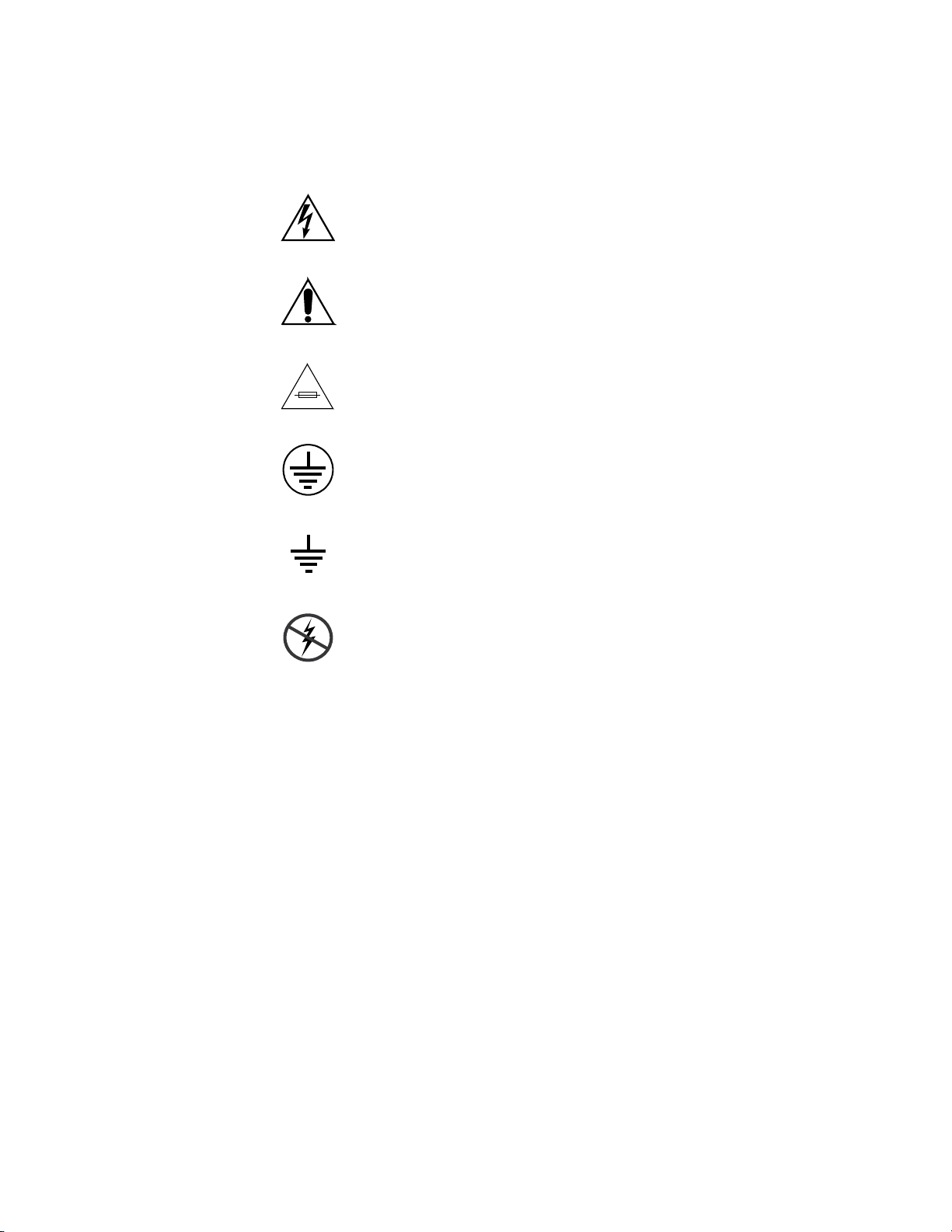
Symbols on the Product
The following symbols may appear on the product:
Indicates that dangerous high voltage is present within the
equipment enclosure that may be of sufficient magnitude to
constitute a risk of electric shock.
Indicates that user, operator or service technician should refer
to product manual(s) for important operating, maintenance,
or service instructions.
This is a prompt to note fuse rating when replacing fuse(s).
The fuse referenced in the text must be replaced with one
having the ratings indicated.
Identifies a protective grounding terminal which must be connected to earth ground prior to making any
connections.
other equipment
Warnings
Identifies an external protective grounding terminal which
may be connected to earth ground as a supplement to an
internal grounding terminal.
Indicates that static sensitive components are present which
may be damaged by electrostatic discharge. Use anti-static
procedures, equipment and surfaces during servicing.
The following warning statements identify conditions or practices that can
result in personal injury or loss of life.
Dangerous voltage or current may be present — Disconnect power and remove
battery (if applicable) before removing protective panels, soldering, or
replacing components.
Do not service alone — Do not internally service this product unless another
person capable of rendering first aid and resuscitation is present.
Remove jewelry — Prior to servicing, remove jewelry such as rings, watches,
and other metallic objects.
Avoid exposed circuitry — Do not touch exposed connections, components or
circuitry when power is present.
14 Jupiter L-S Series Control Panels Installation and Operating Manual
Page 15

Safety Summary
Use proper power cord — Use only the power cord supplied or specified for
this product.
Ground product — Connect the grounding conductor of the power cord to
earth ground.
Operate only with covers and enclosure panels in place — Do not operate this
product when covers or enclosure panels are removed.
Use correct fuse — Use only the fuse type and rating specified for this
product.
Use only in dry environment — Do not operate in wet or damp conditions.
Use only in non-explosive environment — Do not operate this product in an
explosive atmosphere.
High leakage current may be present — Earth connection of product is essential
before connecting power.
Dual power supplies may be present — Be certain to plug each power supply
cord into a separate branch circuit employing a separate service ground.
Disconnect both power supply cords prior to servicing.
Cautions
Double pole neutral fusing — Disconnect mains power prior to servicing.
Use proper lift points — Do not use door latches to lift or move equipment.
Avoid mechanical hazards — Allow all rotating devices to come to a stop before
servicing.
The following caution statements identify conditions or practices that can
result in damage to equipment or other property
Use correct power source — Do not operate this product from a power source
that applies more than the voltage specified for the product.
Use correct voltage setting — If this product lacks auto-ranging power sup-
plies, before applying power ensure that the each power supply is set to
match the power source.
Provide proper ventilation — To prevent product overheating, provide equip-
ment ventilation in accordance with installation instructions.
Use anti-static procedures — Static sensitive components are present which
may be damaged by electrostatic discharge. Use anti-static procedures,
equipment and surfaces during servicing.
Jupiter L-S Series Control Panels Installation and Operating Manual 15
Page 16

Safety Summary
Do not operate with suspected equipment failure — If you suspect product damage
or equipment failure, have the equipment inspected by qualified service
personnel.
Ensure mains disconnect — If mains switch is not provided, the power cord(s)
of this equipment provide the means of disconnection. The socket outlet
must be installed near the equipment and must be easily accessible. Verify
that all mains power is disconnected before installing or removing power
supplies and/or options.
Route cable properly — Route power cords and other cables so that they are
not likely to be damaged. Properly support heavy cable bundles to avoid
connector damage.
Use correct power supply cords — Power cords for this equipment, if provided,
meet all North American electrical codes. Operation of this equipment at
voltages exceeding 130 VAC requires power supply cords which comply
with NEMA configurations. International power cords, if provided, have
the approval of the country of use.
Use correct replacement battery — This product may contain batteries. To
reduce the risk of explosion, check polarity and replace only with the same
or equivalent type recommended by manufacturer. Dispose of used bat
teries according to the manufacturer’s instructions.
-
Troubleshoot only to board level — Circuit boards in this product are densely
populated with surface mount technology (SMT) components and applica
tion specific integrated circuits (ASICS). As a result, circuit board repair at
the component level is very difficult in the field, if not impossible. For war
ranty compliance, do not troubleshoot systems beyond the board level.
-
-
16 Jupiter L-S Series Control Panels Installation and Operating Manual
Page 17

Regulatory Notices
Certifications and Compliances
FCC Emission Control
This equipment has been tested and found to comply with the limits for a
Class A digital device, pursuant to Part 15 of the FCC Rules. These limits
are designed to provide reasonable protection against harmful interference
when the equipment is operated in a commercial environment. This equip
ment generates, uses, and can radiate radio frequency energy and, if not
installed and used in accordance with the instruction manual, may cause
harmful interference to radio communications. Operation of this equip
ment in a residential area is likely to cause harmful interference in which
case the user will be required to correct the interference at his own expense.
Changes or modifications not expressly approved by Grass Valley Inc. can
affect emission compliance and could void the user’s authority to operate
this equipment.
-
-
Canadian EMC Notice of Compliance
This digital apparatus does not exceed the Class A limits for radio noise
emissions from digital apparatus set out in the Radio Interference Regula
tions of the Canadian Department of Communications.
Le présent appareil numérique n’emet pas de bruits radioélectriques
dépassant les limites applicables aux appareils numeriques de la classe A
préscrites dans le Règlement sur le brouillage radioélectrique édicte par le
ministère des Communications du Canada.
EN55022 Class A Warning
In a domestic environment, products that comply with Class A may cause
radio interference in which case the user may be required to take corrective
measures.
-
Jupiter L-S Series Control Panels Installation and Operating Manual 17
Page 18

Regulatory Notices
Canadian Certified Power Cords
Canadian Certified AC Adapter
Safety and EMI Certification
Canadian approval includes the products and power cords appropriate for
use in the North America power network. All other power cords supplied
are approved for the country of use.
Canadian approval includes the AC adapters appropriate for use in the
North America power network. All other AC adapters supplied are
approved for the country of use.
This product has been evaluated for Electromagnetic Compatibility under
the EN 55103-1/2 standards for Emissions and Immunity and meets the
requirements for an E4 environment. This product complies with Class A
(E4 environment). In a domestic environment this product may cause radio
interference in which case the user may be required to take corrective mea
sures.
-
Category Standard Designed/tested for compliance with:
Safety
ANSI / UL60950 “Standard for Safety of Information Technology Equipment - Safety - Part 1: General
IEC 60950 “Standard for Safety for Information Technology Equipment - Safety - Part 1: General
CAN/CSA C22.2, No. 60950 “Standard for Safety of Information Technology Equipment - Safety - Part 1: General
EN60950 Safety of Information Technology Equipment, including Electrical Business Equipment.
73/23/EEC Low Voltage Directive
Requirements”, (ANSI/UL 60950-1, First Edition, Dated April 1, 2003, with revision
through and including November 26, 2003.)
Requirements”, (IEC 60950-1, First Edition, 2001, Corrigendum 1:10-2002)
Requirements”, (CAN/CSA-C22.2 No. 60950-1-03. First Edition Dated April 1, 2003,
with revisions through and including November 26, 2003)
18 Jupiter L-S Series Control Panels Installation and Operating Manual
Page 19
Category Standard Designed/tested for compliance with:
EMC Directive 2004/108/EC
via EN 55103-1 and 2
EN 55103-1 Emission standards
EN55103-2 Immunity standards
EMI
US FCC Class A
Canada FCC Industry Canada
Australia & New Zealand: AS/NZS 3548
Audio, Video and Entertainment Lighting Control for the European Community.
Electromagnetic compatibility.
Product family standard for audio, video, audio-visual and entertainment lighting control
apparatus for professional use.
Part 1 Emissions, Environment E4
EN 55022: Class A Radiated and Conducted Emissions
EN 61000-3-2: Power Line Harmonic Emissions, Radiated Magnetic Field Emissions,
Peak Inrush Current
Electromagnetic compatibility--Product family standard for audio, video, audio-visual
and entertainment lighting control apparatus for professional use.
Part 2 Immunity, Environment E4
EN 50082-1: Immunity
EN 61000-4-2: Electrostatic Discharge “ESD” Immunity
EN 61000-4-3: Radiated RF Electromagnetic Field Immunity
EN 61000-4-4: Electrical Fast Transient/Burst “EFT” Immunity
EN 61000-4-5: Surge Immunity
EN 61000-4-6: Conducted RF Immunity
EN 61000-4-11: Voltage Dips, Short Interruptions and Voltage Variations
Annex A - Radiated Magnetic Field Immunity
Note: This only applies to assemblies sensitive to magnetic fields
CISPR Pub. 22 (1985)
Regulatory Notices
Jupiter L-S Series Control Panels Installation and Operating Manual 19
Page 20

Regulatory Notices
20 Jupiter L-S Series Control Panels Installation and Operating Manual
Page 21

Introduction
Overview
The Jupiter L-S series control panels, are designed to control television
matrix routers through a Grass Valley Jupiter CM-4000 Control System
running the AccuSwitch application. Although the panels are primarily
intended to control Concerto, Trinix, Apex, and Venus routers, any matrix
router that can be controlled by a CM-4000/AccuSwitch can also be con
trolled by these panels.
Note The CM-4000 must be operating with Jupiter AccuSwitch version 7.6 or
Section 1
newer to support the L-S panels.The L-S panels are not intended for use with
CM-4000/JupiterXPress applications nor with Jupiter VM-3000 System Con
trollers.
-
-
The L-S series is comprised of the following units:
• L32, L64, LD4, and LD16
• S25, S50, S100, and SXY
L prefix panels have large (1/2- inch) multi-color buttons. S prefix panels
are equipped with smaller (3/8-inch) multi-color buttons.
L-S panels can be ordered with an AC or DC power supply. The AC power
supply mounts on the rear of the panel. No power switch is present. The
AC or DC line cord is disconnected to power down the panel.
Jupiter L-S Series Control Panels Installation and Operating Manual 21
Page 22
Section 1 — Introduction
Preset
Destination
Status
PresetMenuLevel
Undo
Take
Protect/
Lock
Clear
L Series Control Panel Features
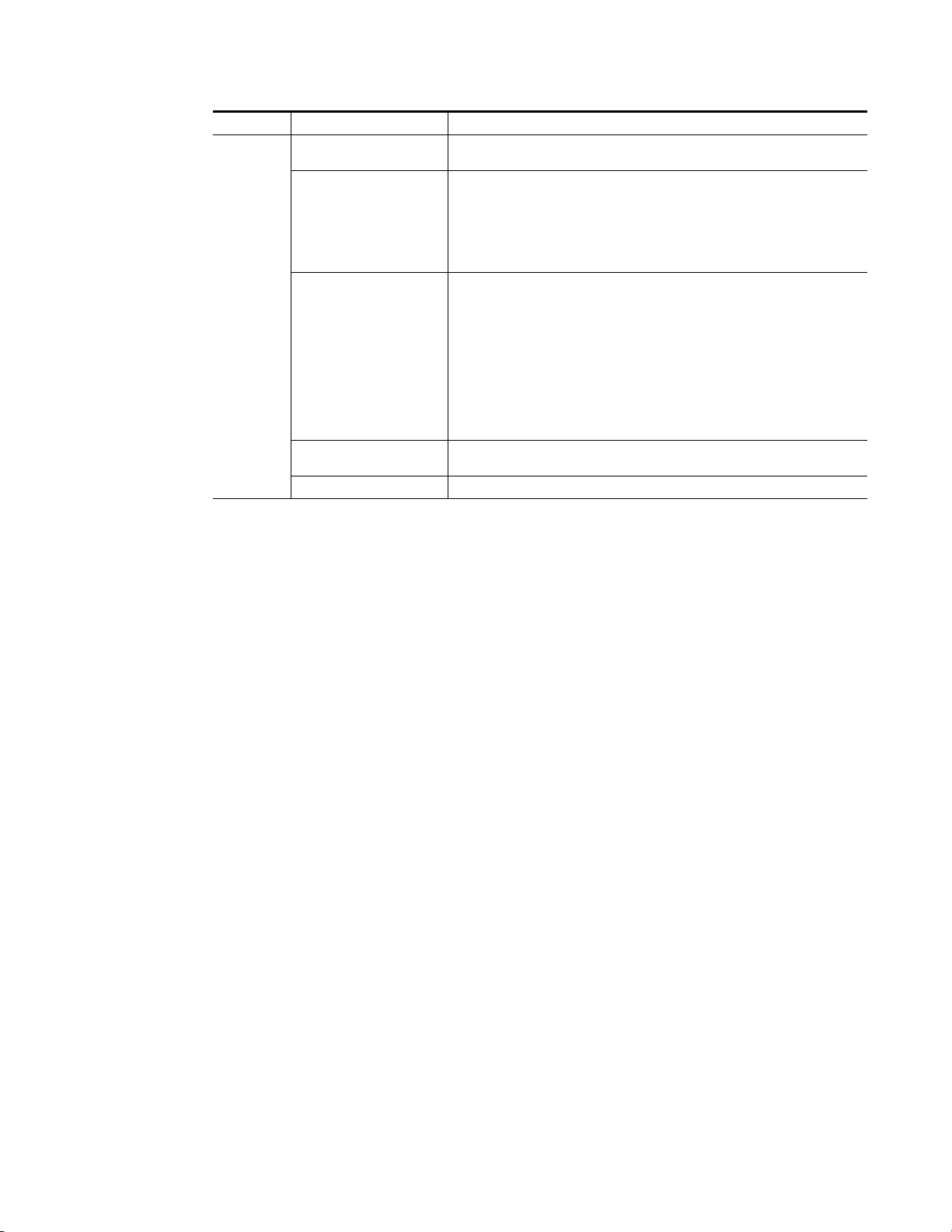
L32
Figure 1. L32 Control Panel
The L32 is a button-per-signal control panel equipped with a Destination/
Status color bitmap display. Features include:
• Assignable buttons on the front panel,
• Locking and protecting destinations,
• Scroll up/down source and destination selection
L64
• Preset mode,
•Overrides,
• Level breakaway, and
• Sequence (Salvo) switching.
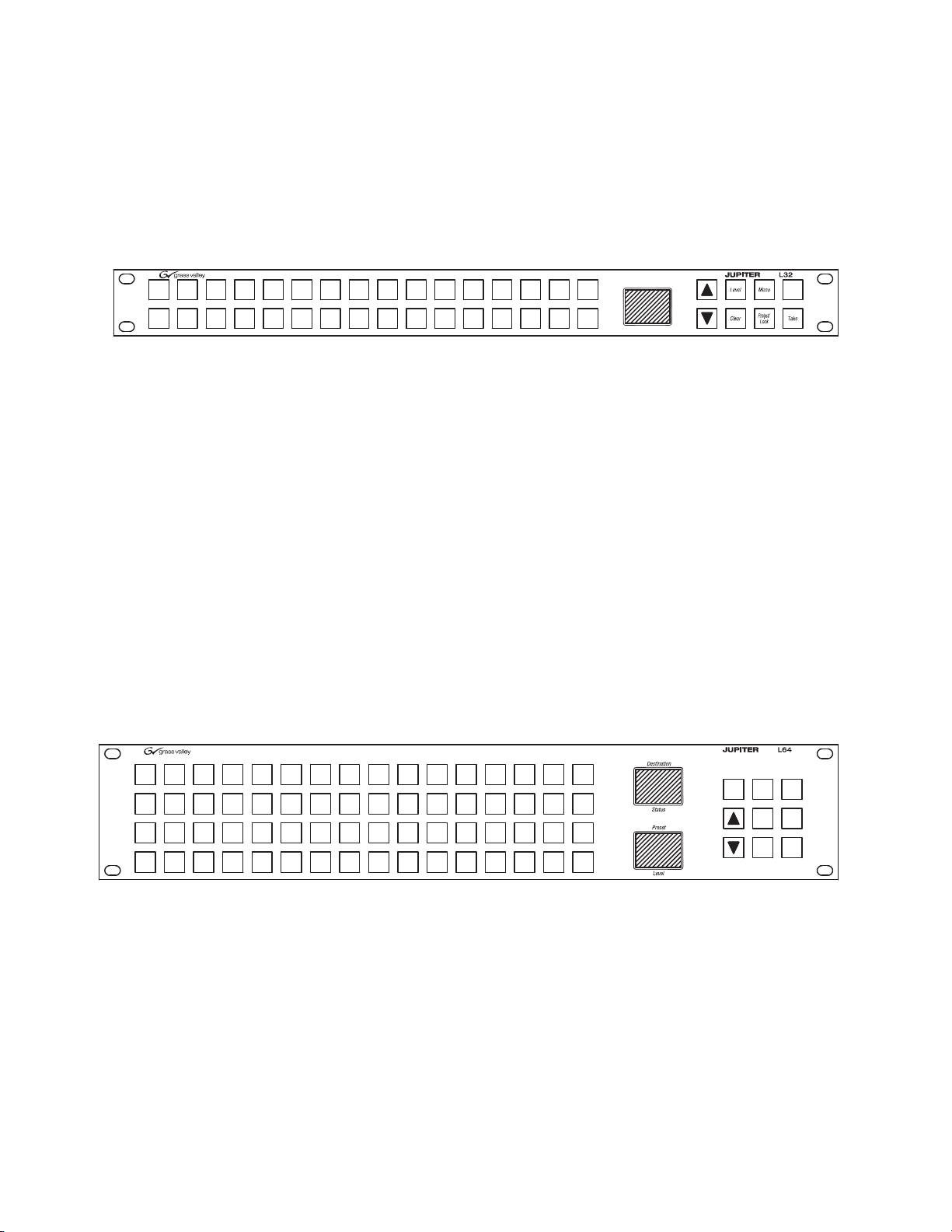
Figure 2. L64 Control Panel
The L64 is a button-per-signal control panel has the same features as the
L32, plus:
• Preset/Level display, and
•Undo.
22 Jupiter L-S Series Control Panels Installation and Operating Manual
Page 23

LD4
L Series Control Panel Features
Figure 3. LD4 Control Panel
The LD4 is a 16-category, full-matrix control panel. The panel provides
multi-level status and control of a single destination (“XY Mode”), or, toplevel status and control of multiple destinations
include:
• Two color bitmap displays showing up to four destinations/page
• Destination/Status color bitmap display
• 16 category buttons for direct category selection
• Locking and protecting destinations
• Scroll up/down source/destination selection
(“MD Control”). Features
• Override
•Level breakaway
• Sticky-level control
• Source swap (flip-flop Take)
•(Salvo) switching
Jupiter L-S Series Control Panels Installation and Operating Manual 23
Page 24
Section 1 — Introduction
Override
Source
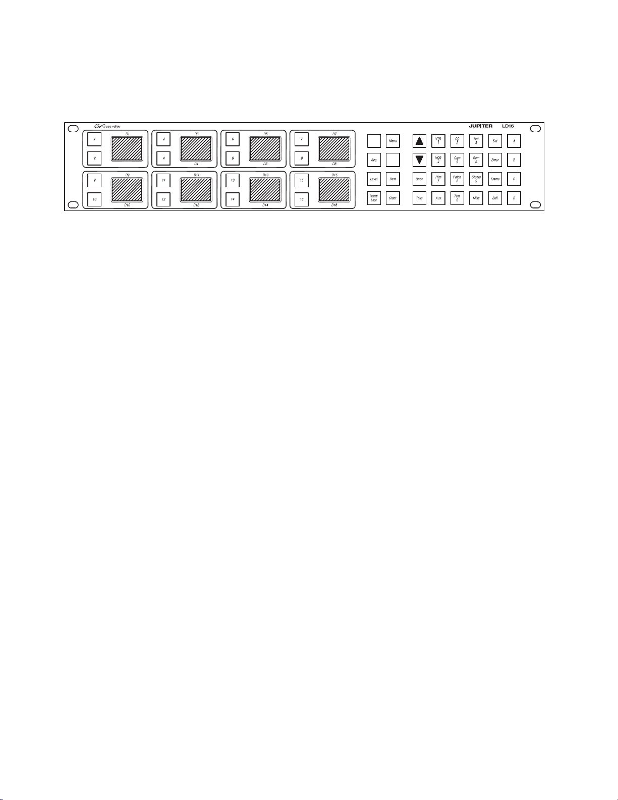
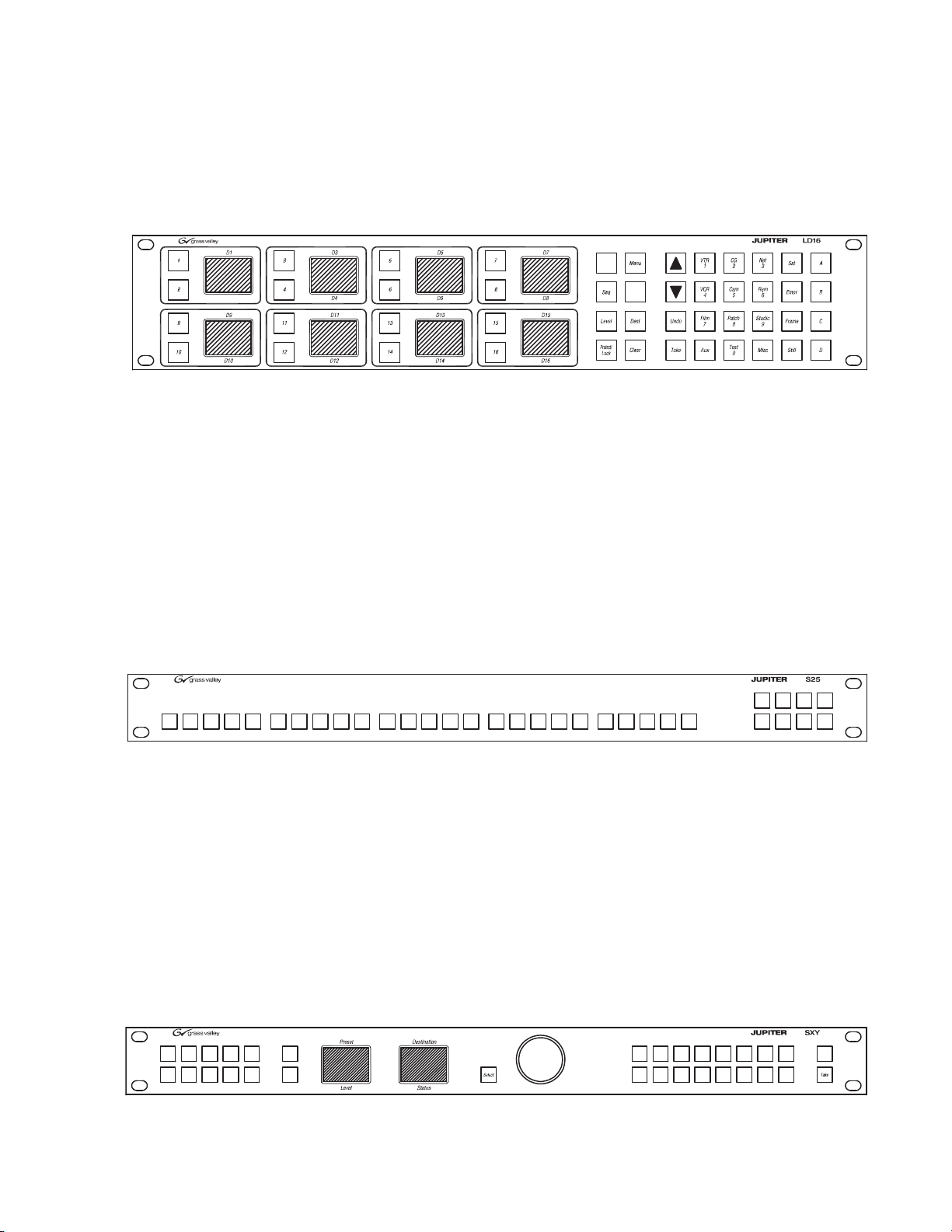
LD16
Figure 4. LD16 Control Panel
The LD16 is a 20-category, full-matrix, multi-level breakaway control panel.
The panel provides multi-level status and control of a single destination, or,
top-level status and control of multiple destinations (“MD Control”). Features include:
• Eight color bitmap displays showing up to 16 destinations/page,
• 20 category buttons for direct category selection,
• Locking and protecting destinations,
• Scroll up/down source/destination selection,
•Undo,
• Override,
• Level breakaway,
• Sticky-level control,
• Source swap (flip-flop Take), and
• Sequence (Salvo) switching.
24 Jupiter L-S Series Control Panels Installation and Operating Manual
Page 25
S Series Control Panel Features
S50
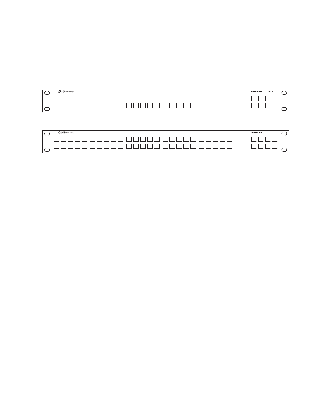
S25/S50
Figure 5. S25 Control Panel
S Series Control Panel Features
Figure 6.
The S25 (Figure 5) and S50 (Figure 6) panels provide button-per-source
routing switcher control with 25 (or 50) sour
destination / level selection cluster. Other panel features include:
•Level breakaway, and
• Configurable for various combinations of destinations and levels:
S50 Control Panel
ce buttons and an eight-button
• Control of one destination and br
levels, or
• Control of two, three, or four destinations and
for four levels, or
• Control of five, six, seven, or eight destinations without breakaway
itching.
sw
eakaway switching for eight
breakaway switching
Jupiter L-S Series Control Panels Installation and Operating Manual 25
Page 26
Section 1 — Introduction
Protect/
Lock
Panel
ID
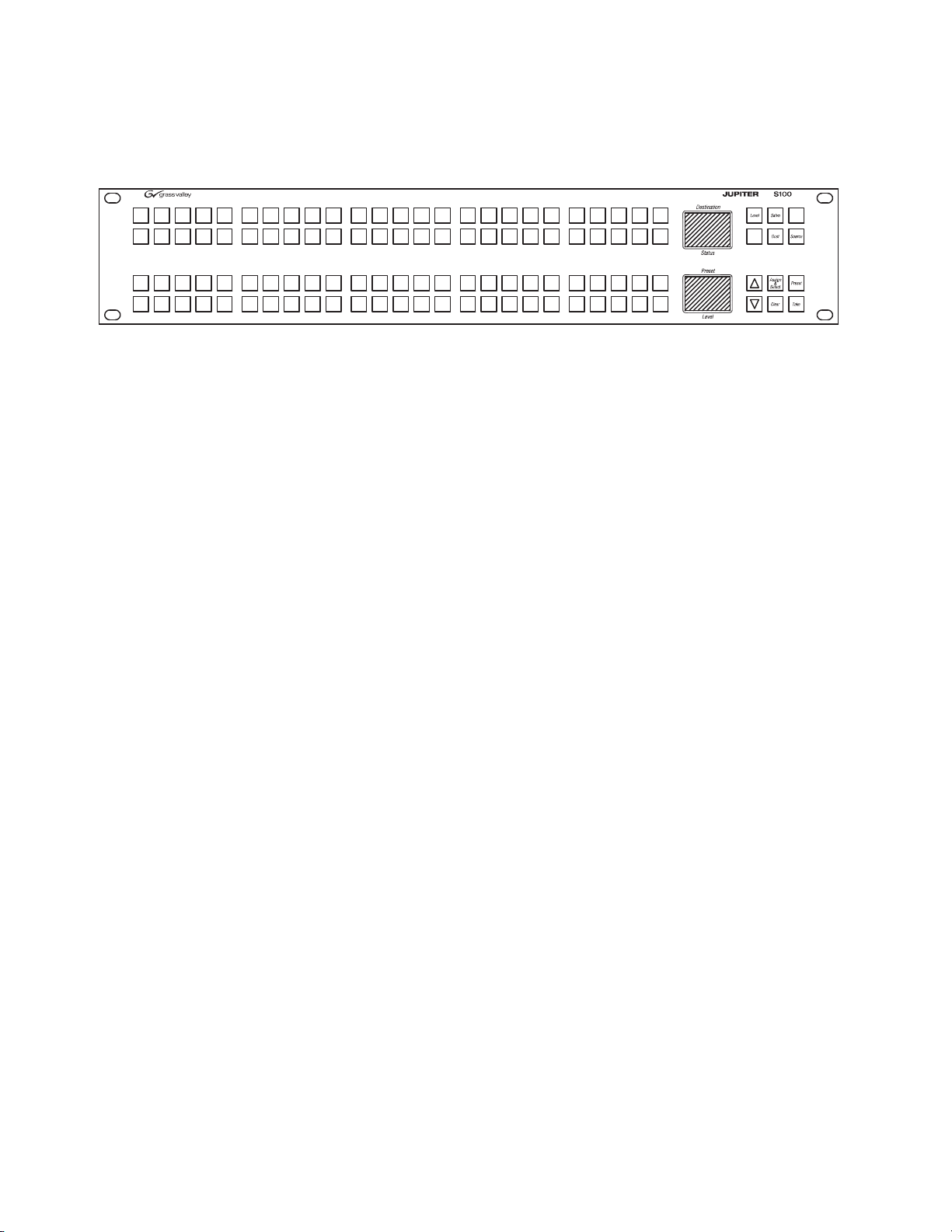
S100
Figure 7.
S100 Control Panel
The S100 is a 100 button-per-source control panel. The panel includes two
color bitmap displays (Destination/Status and Preset/Level) and buttons
for scrolling through every available source or destination, plus a button
for level selection. Features include:
• Assignable buttons on the front panel,
• Locking and protecting destinations,
• Scroll up/down source/destination selection,
• Preset mode,
• Level breakaway,
• Sticky-level control, and
• Sequence (Salvo) switching.
26 Jupiter L-S Series Control Panels Installation and Operating Manual
Page 27

SXY
Level
Clear
Protect/
Lock
Specifications
Figure 8. SXY Control Panel
The SXY is a single destination control panel that includes two color bitmap
displays (Destination/Status and Preset/Level). Category/number keys
and a rotating selector knob ca
n be used for source, destination, or level
selection. Features include:
• Quick selection knob,
• Locking and protecting destinations,
• Override,
•Level breakaway,
• Sticky-level control,
Specifications
• Source swap (flip-flop Take),
• Sequence (Salvo) switching, and
• Scroll Take.
For mechanical, connection, power, and environmental specifications, refer
to Appendix A-Specifications.
Jupiter L-S Series Control Panels Installation and Operating Manual 27
Page 28

Section 1 — Introduction
Ordering Information
JUP-CP-L32 Series Control Panels
JUP-CP-L32-AC 32 button per source control panel, with the ability to choose any source or destination
JUP-CP-L32-DC 32 button per source control panel, with the ability to choose any source or destination
JUP-CP-L64 Series Control Panels
JUP-CP-L64-AC 64 button per source control panel, configurable. Includes buttons for TAKE, LOCK/PRO-
JUP-CP-L64-DC 64 button per source control panel, configurable. Includes buttons for TAKE, LOCK/PRO-
JUP-CP-LD4 Series Control Panels
JUP-CP-LD4-AC XY, Sixteen category, full featured routing switcher control panel. Includes three displays
JUP-CP-LD4-DC XY, Sixteen category, full featured routing switcher control panel. Includes three displays
JUP-CP-LD16 Series Control Panels
JUP-CP-LD16-AC XY or multiple destination control panel. Twenty category, full featured routing switcher
JUP-CP-LD16-DC XY or multiple destination control panel. Twenty category, full featured routing switcher
JUP-CP-S25 Series Control Panels
JUP-CP-S25-AC 25 x 1 Single Bus control panel. Pushbutton-per-source routing switcher control panel
JUP-CP-S25-DC 25 x 1 Single Bus control panel. Pushbutton-per-source routing switcher control panel
JUP-CP-S50 Series Control Panels
JUP-CP-S50-AC 50 x 1 Single Bus, Pushbutton-per-source routing switcher control panel with 50 source
JUP-CP-S50-DC 50 x 1 Single Bus, Pushbutton-per-source routing switcher control panel with 50 source
JUP-CP-S100 Series Control Panels
JUP-CP-S100-AC 100 button per source control panel. 2U, two displays for destination, status, presets and
JUP-CP-S100-DC 100 button per source control panel. 2U, two displays for destination, status, presets and
included in the input or output table. Includes one display. Rack or desk mount 1 RU.
Includes AC power supply (JUP-ACPS-1RU).
included in the input or output table. Includes one display. Rack or desk mount 1 RU.
Includes DC power supply. (JUP-DCPS).
TECT, LEVELS, AND PRESETS. Includes two displays. Rack or desk mount 2RU. Includes
AC power supply. (JUP-ACPS-2RU).
TECT, LEVELS, AND PRESETS. Includes two displays. Rack or desk mount 2RU. Includes
DC power supply. (JUP-DCPS).
and buttons for SOURCES, DESTINATIONS, SALVOS, and LEVELS. Categories are user
definable with relegendable buttons. Includes AC power supply. (JUP-ACPS-2RU).
and buttons for SOURCES, DESTINATIONS, SALVOS, and LEVELS. Categories are user
definable with relegendable buttons. Includes DC power supply. (JUP-DCPS).
control panel. Includes 8 displays and buttons for SOURCES, DESTINATIONS, OVERRIDES, and LEVELS. Categories are user definable with relegendable buttons. Rack or
desk mount 2 RU. Includes AC power supply. (JUP-ACPS-2RU).
control panel. Includes 8 displays and buttons for SOURCES, DESTINATIONS, OVERRIDES, AND LEVELS. Categories are user definable with relegendable buttons. Rack or
desk mount 2 RU. Includes DC power supply. (JUP-DCPS)
with twenty-five source selection and eight level selection pushbuttons. Rack or desk
mount 1RU. Includes AC power supply. (JUP-ACPS-1RU)
with twenty-five source selection and eight level selection pushbuttons. Rack or desk
mount 1RU. Includes DC power supply (JUP-DCPS).
selection and eight level selection pushbuttons. Rack or desk mount 1RU. Includes AC
power supply (JUP-ACPS-1RU).
selection and eight level selection pushbuttons. Rack or desk mount 1RU. Includes DC
power supply (JUP-DCPS).
levels. Joystick Override. Buttons for scrolling through every available source or destina
tion, and level selections. Includes AC power supply (JUP-ACPS-2RU)
levels. Joystick Override. Buttons for scrolling through every available source or destina
tion, and level selections. Includes DC power supply (JUP-DCPS)
-
-
28 Jupiter L-S Series Control Panels Installation and Operating Manual
Page 29

Ordering Information
JUP-CP-SXY Series Control Panels
JUP-CP-SXY-AC XY, multiple level control panel. Category entry, quick-pick or Scroll Wheel for source,
JUP-CP-SXY-DC XY, multiple level control panel. Category entry, quick-pick or Scroll Wheel for source,
destination or level selection, with two displays for statusing: destinations, presets, levels
and current status. Includes AC power supply (JUP-ACPS-1RU).
destination or level selection, with two displays for statusing: destinations, presets, levels
and current status. Includes DC power supply (JUP-DCPS).
Jupiter L-S Series Control Panels Installation and Operating Manual 29
Page 30

Section 1 — Introduction
30 Jupiter L-S Series Control Panels Installation and Operating Manual
Page 31

Hardware Installation
8536_43
44 mm
1.75 in.
88 mm
3.5 in.
432 mm
17 in.
483 mm
19 in.
2 RU Panel
1 RU Panel
This section describes hardware installation procedures for the L-S series
hardware panels.
Rack Mounting
Jupiter L-S panels mount into a standard 19 in. equipment rack. Panels are
1 or 2 rack units high (Figure9).
Figure 9. Panel Rack Mounting
Section 2
See Specifications on page 101 for dimensions for each type of L-S panel.
Power Supplies
Two methods are available for powering the L-S series hardware panels:
Jupiter L-S Series Control Panels Installation and Operating Manual 31
• AC power supply (JUP-ACPS)
• DC power supply (JUP-DCPS)
The module used is specified at the time of order.
Page 32

Section 2 — Hardware Installation
8536_37
8536_37
All power modules are auto-sensing (120-240 VAC, 50-60 Hz) and are supplied with a mains power cable appropr
tion. No power switch is present. The AC cord is disconnected to power
dow
WARNING Do not connect any external power supply other than the approved “JUP-
The AC power supply is contained in a module that mounts on the rear of
the panel (Figure10).
Figure 10. Control Panel Dimensions with Options
iate for the user’s geographic loca-
n the panel.
DCPS” unit supplied by Thomson Grass Valley.
32 Jupiter L-S Series Control Panels Installation and Operating Manual
Page 33

Network Wiring
LAN 1 (Cat 5 Ethernet) cable.
Max. recommended length per
segment = 100 meters (329 ft)
CM-4000
System
Controller
(AccuSwitch)
100baseT Jupiter LAN
to Jupiter
File Server
64 LAN-operated
L-S panels per CM
maximum
8536_08
IP switch
Network Wiring
The L-S series panels are connected to the CM-4000 System Controller via
Ethernet. Maximum length of a LAN (Cat5 cable) connection is 329 feet
(100 meters). The LAN must be capable of 100 Mb operation, and each
Ethernet segment (hub to panel) has a 100 meter limit. See Figure11.
Figure 11. LAN only system connections.
Button Labels
Most L-S series panels are supplied with “typical use” button labels already
installed. Additional buttons can be labelled in the field. Two resources are
available for labels:
• A pre-printed/pre-cut transparency keycap label sheet is supplied with
each panel. See Keycap Transparency Labels on page 36.
• Microsoft Word files are available for cr
information, contact Grass Valley Technical Support.
eating custom labels. For more
Jupiter L-S Series Control Panels Installation and Operating Manual 33
Page 34

Section 2 — Hardware Installation
Preset
Destination
Status
VTR1VTR2VTR3VTR4VTR
5
VTR7VTR8VTR
9
VTR
6
VTR
1
CG
2
NET
3
VCR
4
1234
CAM
5
AUX EJ SS
5
678
REM
6
FILM
7
PTCH
8
STU
9
910
11 12
TEST
0
SAT FS MISC
13
14 15 16
8536_42
L32/L64/S100 Panels
The L32 and LD64 panels have 32 or 64 buttons respectively, on the left side
of the panel that can be used for button-per-source operation. The S100
panel has 100 buttons for this purpose. Using the label resources described
above, these buttons can be labelled 1 through 32, 64, or 100.
Figure 12. L32 with Custom Labels
If the button assignments are more or less permanent, you may want to
label them more specifically. An example is shown in Figure12. See Source
Button Configuration on page 36 for more information.
LD4 Panels
The LD4 panels have a cluster of 16 buttons on the right side that can be
used for category/number operation. See Figure13.
Figure 13. LD4 Control Panel
These buttons have default categories assigned, as shown in Figure14.
Figure 14.
Type CP-ESLAN Input Set Default Categories
It is possible to configure the panel with a custom category set. Note that
the button order of the set is grouped with the first 10 entries on the left and
the following 6 entries on the right. See Category Button Configuration on
page 36 for more information.
34 Jupiter L-S Series Control Panels Installation and Operating Manual
Page 35
LD16 Panels
Override
Source
1234
5
67
8
9
10
S25/S50
Button Labels
The LD16 includes a button cluster on the right side of the panel that can be
used for category/number selection. The default is shown in Figure15.
Figure 15. LD16 with Type ESL Category Set
It is also possible to configure the panel with a custom category set. See Cat-
egory Button Configuration on page 36 for more information.
The S25 and S50 panels have 25 or 50 buttons on the left side of the panel
that can be used for “button-per-source” operation. Using the label sheet,
these buttons can be labelled 1 through 25 (or 50). If the button assignments
are more or less permanent, it might be desirable to label them more specifically. See Source Button Configuration on page 36 for more information.
Figure 16. S25
These panels also include a cluster of eight buttons on the right side that
can be configured and labeled to select router levels. See CP Level Set on
page 51 for more information.
SXY Panels
The SXY panels include a cluster of buttons on the left side that can be configured and labeled to select router levels. See CP Level Set on page 51 for
more information.
Jupiter L-S Series Control Panels Installation and Operating Manual 35
Figure 17.
Level
Clear
SXY Control Panel Showing Level Buttons
Protect/
Lock
Page 36

Section 2 — Hardware Installation
The SXY panels also have a cluster of 16 buttons on the right side that can
be used for category/number operation. See
on page 36 for more information.
Button Configuration Overview
Source Button Configuration
Source button functions are assigned on a panel by creating a Jupiter CP
Input set of type CP-ESLAN. The set table in this Input set consists of a list
of button numbers and the name of the router input associated with each
button. The CP Input set is assigned to the panel using the MPK Devices
table.
For more information about button configuration, see CP Input and CP
Output Sets on page 51.
Category Button Configuration
Category Button Configuration
Category buttons exist on some panels, allowing the pre-selection of categories of sources or destinations. The categories can be customized, by creating a custom Jupiter CP Category set table. This CP Category set would
then be assigned to the CP Input set, which would in turn be assigned to
the panel using the MPK Devices table.
For more information about button configuration, see CP Input and CP
Output Sets on page 51.
Level Button Configuration
Some panels include a cluster of eight buttons on the right side that can be
configured and labelled to select router levels. This can be done by creating
a suitable CP Level set which lists the router levels in the order they should
be available using the eight buttons. The CP Level set is assigned to the
panel using the MPK Devices table.
For more information about level button configuration, see CP Level Set on
page 51.
Keycap Transparency Labels
A sheet of pre-cut transparency keycap labels, part no. 335835400, is available for use with Jupiter L-S Series control panels. The large labels measure
0.38 x 0.38 inches (9.65 x 9.65 mm). The small labels measure 0.3 x 0.3 inches
(7.62 x 7.62 mm). The font is Helvetica condensed oblique See
36 Jupiter L-S Series Control Panels Installation and Operating Manual
Figure18.
Page 37

Figure 18. Pre-Cut Transparency Keycap Labels
Shift
Source
Store
Take
Undo
Router and Control Systems
10099
8079
6059
4039
JEP Series Small and Large Button Keycap Legend Set
GV Part Number 335-8354-00A1
ID
2019
Red
Gold
Blue
Lock
Hold
Protect/
Protect/
Select
Ride
Still
Panel
Over
&
Assign
Keycap Legends for JEP "L" series Large Buttons
22
62
82
42
9897
77 78
9695
7675
5857
37 38
5655
3635
9493
73 74
91 92
71 72
5453
33 34
51 52
31 32
46
86
66
26
88
68
9089
7069
87
67
48
28
5049
29 30
47
27
846485
65
83
63
442445
25
43
23
81
61
41
21
Keycap Legends for JEP "S" series Small Buttons
Cam
Cam
Cam
Cam
Cam
Cam
Cam
Cam
Cam
Cam
Cam
222222 22222
Studio
Studio
Studio
Studio
Studio
Studio
Studio Frame
1817
Store
Seq
1615
T
Frame Select
Enter Sat
S
R
1413
VTR
9
J
1211
Test9VCR
9
VTR
8
I
VTR
7
H
Test8VCR
8
Test VCR
77
Emer Salvo
Protect
Edit
Q
P
Dest Preset
Clear Misc
OZ
NY
444
VTR
6
G
5
VTR
F
6
Test6VCR
5
Test5VCR
3
VTR
E
D
VTR
33
Test VCR
Test VCR
Patch
7
8
9
6
Patch
Patch
109
Server
99
87
Rem
9
88
Server
Server
77
Rem
8
Rem
7
Film
9
45
Net
9
32
CG
99
Film
7
8
Film Net
8
Net
7
CG
88
CG
77
3
4
5
6
Patch
Patch
Patch
Patch
444
66
Server
55
Server
6
Rem
5
Rem
33
Server
Server
3
Rem
Rem
4444
5
6
Film
Film
6
Net
5
Net
6CG6
5CG5
3
Film
Film
3
Net
Net
33
CG
CG
VTR
73
93
53
33
13
Studio
Studio
Studio
Chop Menu
Aux Lock
W
LV
Audio LevelKU
10099
000
1
VTR
CM
B
VTR
11
Test VCR
Test VCR
VTR
A
9896 97
Test VCR
94 95
4039
8079
6059
2019
Red
34 35 3836 37
7876 77
5856 57
74 75
54 55
1816 17
Store
Frame
Seq
14 15
J9T
0
Patch
Patch
Patch
000
11
Server
Server
1
Rem
Rem
Server
9291
Rem
908988
0000
1
Film
Film
11
Net
Net
11
CG
CG
85
Film Net
86 87
CG
83 84
3028 29 3231
7271
5251
7068 69
5048 49
Studio
1211
Test VCR
99
1098
Server
99
23 24 272625
65456766
46 47
63 64
43 44
Net
675
RemPatch
999
43
FilmCG
99
2
1
Aux
9
Aux
8
Aux
7
4
6
Aux
5
Aux
3
Aux
Aux
0
1
Aux
Aux
Aux
81 82
21 22
61 62
41 42
21
Aux
99
Cam
Cam
Cam
Cam
Cam
Cam
Cam
Cam
Cam
VTR
VTR
VTR
VTR
VTR
VTR
VTR
VTR
VTR
3 Hold
Protect
Salvo
Select
Preset
Gold
Blue
Undo
Protect/
Lock
Take
G Q Emer
Frame
SatEnter
7
8
IS
6
HR
Z Edit
DestX
F5P
4
EO
Lock
Level
Menu
Misc
Over
Still
Store
ID
Protect/
Source
Ride
Panel
Shift
Assign
Select
&
W Chop
Y Clear
V Aux
CM
2
DN
B1L
U AudioA0K
333333333
TestStudio VCR
Server
Studio
Studio
77
8
Test8VCR
66
Test VCR
77
88
Server
66
Server
Studio
Studio Test5VCR
5
Test VCR
44
55
Server
Server
44
FilmCG RemPatchNet
Net
Net
777
88
RemPatch
8
666
RemPatch
77
88
FilmCG
66
FilmCG
Net
Net RemPatch
555
RemPatch
444
FilmCG
55
FilmCG
44
TestStudio VCR
Server
Studio
Studio2Test2VCR
11
Test VCR
22
Server
11
Server
Studio Test0VCR
000
Server
FilmCG RemPatchNet
Net
Net
22
RemPatch
2
111
RemPatch
22
FilmCG
11
FilmCG
Net0RemPatch
00
FilmCG
00
33
Aux
77
88
Aux
66
Aux
Aux
55
Aux
44
Aux
22
Aux
11
Aux
Aux
00
Tally/
Level
ID
Panel
Enable
All
Level
Config
Tally/
Level
ID
Panel
Enable
All
Level
Config
Button Labels
Jupiter L-S Series Control Panels Installation and Operating Manual 37
Page 38

Section 2 — Hardware Installation
38 Jupiter L-S Series Control Panels Installation and Operating Manual
Page 39

Software Installation & IP Addresses
Introduction
The L-S series panels operate with the Jupiter AccuSwitch control system
using Ethernet LAN connections. This functionality requires compatible
software versions and IP addresses must be used by all Jupiter system
devices on the network.
L-S series hardware panels are shipped with the current software installed.
There is no need to install panel software on newly shipping systems. How
ever, the IP address must be set on each panel so it can operate on the network. The NetConfig application is used to discover and set IP addresses
of the L-S series panels. NetConfig is also used to update L-S series panel
software, by transferring panel code from the computer running NetConfig
directly to the panels. The L-S panels communicate with the CM4000 con
troller boards via the ESLAN protocol. Once communications is established, the L-S panels will receive their operational configurations from the
Jupiter CM4000 controller.
Section 3
-
-
The panel software update mechanism above is different from that used by
the Jupiter control system itself. Jupiter (VM, SI, CM-4000) controller
boards update their software via Bootstrap Protocol (bootp) and Trivial File
Transport Protocol (tftp) when activating a configuration. The controller
boards send out a “bootp” request and the file server responds by indi
cating what files need to be downloaded from where. The controller boards
then use tftp to download the files from the Jupiter file server. The files
consist of the.sys files (accuswch.sys, jupiter.sys) and a.cfg file. The .sys file
is the operating system and the .cfg file is for configuration. The .sys file is
installed during the Jupiter install process and the .cfg file is created after
compiling the configuration and activating it.
Note The Jupiter Control Center and NetConfig use the same tftp port. NetConfig
cannot be used to send software to the control panels if the Jupiter Control
Center is running. Configuration changes from the Jupiter Control Center
could also be interrupted if NetConfig is running at the same time, depending
which application has the port bound.
Jupiter L-S Series Control Panels Installation and Operating Manual 39
-
Page 40

Section 3 — Software Installation & IP Addresses
Software Installation
NetConfig Installation
The Grass Valley NetConfig application is supplied on the L-S Panels Software CD that is shipped with the panel.
1. Insert the Jupiter L-S Panels Software CD into the Jupiter file server
computer. The NetConfig Setup application should automatically run
and display a Welcome screen (Figure 19).
Figure 19. NetConfig Installation Welcome Screen
40 Jupiter L-S Series Control Panels Installation and Operating Manual
Page 41

Software Installation
2. Click Next and follow the instructions shown on the screens, accepting
the defaults (Figure 20).
Figure 20. NetConfig Installation Screens
3. After NetConfig has successfully installed, click Finish.
Jupiter L-S Series Control Panels Installation and Operating Manual 41
Page 42

Section 3 — Software Installation & IP Addresses
L-S Panels Installation (on Jupiter File Server)
1. After NetConfig has been installed, the L-S Panels installation
application will launch. This program loads files from the CD onto the
computer running the installer program. You can later use NetConfig
to install the software directly on the L-S series panels (Figure 21).
Figure 21. L-S Panels Installation Welcome Screen
2. Click Next and follow the instructions shown on the subsequent screens,
accepting the defaults (Figure 22).
Figure 22. L-S Panels Installation Screens
42 Jupiter L-S Series Control Panels Installation and Operating Manual
Page 43

3. Click Finish when the L-S Panels software installation completes.
CM-4000 System Controller
10/100baseT
Jupiter LAN
IP switch
Panel IP
192.168.253.102
Panel ID
02
Panel IP
192.168.253.101
Panel ID
01
Panel IP
192.168.253.164
Panel ID
64
Jupiter
File Server IP
192.168.253.1
IP
192.168.253.10
8536_13
NOTE: 64 Panels per CM maximum
Network IP Addresses
This section describes IP (LAN) addressing procedures for the L-S series
hardware panels.
IP connection and configuration allows Ethernet operation and provides a
downloading path for
and Jupiter file server PC must be on the same IP network, or be connected
through a network router/gateway.
Single Network IP Configuration
Figure 23 shows an example with the Jupiter equipment (file server, CM-
4000, and L-S panel) is in an is
Network IP Addresses
software upgrades. The L-S panel, Jupiter CM-4000,
olated network environment.
Figure 23. LAN System Addressing Eample.
Jupiter L-S Series Control Panels Installation and Operating Manual 43
Page 44

Section 3 — Software Installation & IP Addresses
CM-4000 System Controller
10/100baseT
Jupiter LAN
IP switch
Panel IP
192.168.253.102
Panel ID
02
Panel IP
192.168.253.101
Panel ID
01
NOTE: 64 Panels per CM maximum
Panel IP
192.168.253.103
Panel ID
03
Jupiter
File Server IP
192.168.253.1
IP
192.168.253.10
8536_17r1
Remote L-S panel
Gateway
Facility LAN
IP
192.168.1.1
Remote Panel IP:
192.168.1.164”
Gateway:
192.168.1.1
Panel ID
64
Multi-Network IP Configuration
A “remote” L-S panel can be placed on a network separate from the other
Jupiter devices. For example, on a facility LAN. In Figure 24, an IP router
serves as a gateway between two networks.
Figure 24. LAN Addressing With Remote L-S Panel Example
Configuration is similar to that just described, except that the address of the
gateway must be entered on the web page for the remote panel.
For more information on IP addressing, see the Jupiter CM-4000 Installation
and Operating Manual.
Network Configuration Procedure (NetConfig)
The network configuration procedure requires the Grass Valley NetConfig
application v2.0.9 or newer. NetConfig is supplied on the CD shipped with
the panel (see NetConfig Installation on
page 40).
44 Jupiter L-S Series Control Panels Installation and Operating Manual
Page 45

The network configuration procedure consists of two parts:
• Setting the panel IP address, subnet value, and gateway address, and
• Setting the panel “Device Number” and other Jupiter values.
Setting IP Addresses on L-S Panels
When L-S panels are being installed for the first time, the user will need to
load the NetConfig application on the Jupiter file server PC.
Note The following is a summary of the NetConfig portion of the configuration pro-
cess. For a complete description of the NetConfig application, refer to the
NetConfig Instruction Manual.
1. Connect the panel to the IP switch on the Jupiter network. Apply
power. If the panel has a display window, you should see the default IP
address of the panel.
If there are other devices on the Jupiter LAN with this same address,
they should be disconnected at this time.
Network IP Addresses
2. Launch the NetConfig application from the control-system file server.
3. Expand the “IP View.”
You should see the Jupiter file server name and IP address.
4. Expand the listing under the Jupiter file server.
You should see the panel name and the factory default address of the
panel(s). In most cases, you will see a red dot next to the panel name,
meaning that the panel address needs to be changed as described
below.
If you do not see the panel name(s) that you expect:
• Select “Configure > Netconfig Options > Clear Views and Re-dis-
cover.”
• Check to see that the “IP View > Product Web Access Pages” are not
being covered by other views, such as “Device view” or “Facility
View.”
In some cases, you may need to cycle power to the panel.
5. Change the panel IP address to place the panel on the Jupiter network:
a. Select the panel requiring an address change.
b. Select the “Set IP” button along the top of the NetConfig window.
You should see the “Change IP Addresses” menu.
c. In the “Select Device Type” field, select “All Devices.”
d. Select the panel requiring an address change.
Jupiter L-S Series Control Panels Installation and Operating Manual 45
Page 46

Section 3 — Software Installation & IP Addresses
e. Select “Edit.”
f. IP address - set to a unique value within the same network as the
Jupiter file server.
For example, if the Jupiter file server address is 192.168.253.1, then
the panel address should be changed to reside in the 192.168.253.x
network (such as “192.168.253.101”).
g. Subnet Mask - set to 255.255.255.0 (Class C network).
h. Gateway - not used in a simple network environment.
If the panel and the server are on separate networks, the gateway
connecting them must be specified. See
i. Select “OK,” “Apply Changes,” and “Close.”
In the IP View, a green dot should indicate that the panel is fully
connected.
The panel itself should reboot.
j. Proceed to Setting Jupiter Values for L-S Panels below.
page 44.
Setting Jupiter Values for L-S Panels
During the following steps, you will need to know the IP address of the
CM-4000 that will be associated with the panel. Use the Jupiter File Server
JNS Control Center application to determine the CM-4000 IP address (the
Control Center application is described in the Jupiter CM-4000 Installation
and Operating Manual).
1. Using NetConfig, click on the name of the panel (as described in Step 4
above).
You should see the Product Web Access page for the panel.
2. Select “Panel Network.”
You should see the Panel Network Configuration page.
a. The “Net-1 IP Settings” should already be correct (they were set
using the “Change IP Addresses” menu described above).
b. Uncheck “Net-1: Set DHCP Mode” and “Net-2: Set DHCP Mode”
(unless IP addresses are being set automatically by a Dynamic Host
Configuration Protocol server).
c. ES-Lan/Serial Device #:
LAN only system: enter a number from 1 to 64. Each panel connected to an AccuSwitch controller must be given a unique number.
The “Device #” is referred to as the “Device Id” on the panel itself
and the “Address” on the Jupiter MPK Devices table. See
Section 4-Jupiter System Configuration.
46 Jupiter L-S Series Control Panels Installation and Operating Manual
Page 47

Finding the Physical Location of a Panel
Note Serial communications is not currently supported.
d. ES-LAN Primary Host IP: enter the IP address of the CM-4000
associated with this panel.
e. ES-Lan Secondary Host IP: enter the IP address of the redundant
CM-4000 (if any).
3. Select “Save New Settings.”
This will apply the settings and reboot the panel. You should see some
type of status response from the router
4. Go to the next panel and repeat the steps above.
Note For initial installations, the Jupiter/AccuSwitch control system must be con-
figured in order for the CM-4000 to communicate with the panel. Proceed to
Section 4-Jupiter System Configuration.
Finding the Physical Location of a Panel
NetConfig can be used to send an “identify device” signal to a particular
panel, causing the panel to display a flashing red and yellow checkerboard
pattern.
1. Use Device View and go to Router > Jupiter > Panels.
2. Expand the panel type name and right click on the name of the panel of
interest.
3. Select “Identify Device” from the pop-up menu.
The panel will flash the checkerboard pattern for the number of seconds set
in the Options menu.
L-S Panel Software Update
Note NetConfig and the Jupiter Control Center use the same TFTP port. Only one
will own the port at a time. When updating control panel software the Jupiter
Control Center should be shut down, and NetConfig must be closed to send
any Jupiter configuration changes.
NetConfig is used to update the operating software that resides on each L-S
series panel. NetConfig accomplishes this by sending the flash files
installed onto the computer running NetConfig (Jupiter file server recom
mended) to the panels via the network. For this reason, panel IP addresses
Jupiter L-S Series Control Panels Installation and Operating Manual 47
-
Page 48

Section 3 — Software Installation & IP Addresses
must be set correctly before L-S panel software can be updated. See Setting
IP Addresses on L-S Panels on page 45 for more information.
1. Launch NetConfig.
Note If NetConfig is already installed you can Cancel its installation.
2. Click on the Load Software tab at the top of the NetConfig screen. The
software load window will open (Figure 25).
Figure 25. L-S Panels Installation Welcome Screen
3. Navigate to the Jupiter/Panels folder in the left pane and select the type
of panel whose software you wish to update.
4. Select the specific panel(s) in the right pane you wish to update.
5. Ensure the Re-Boot when complete box on the lower right is checked.
6. Click Load. The software will be loaded to the selected panels and the
panels will reboot.
48 Jupiter L-S Series Control Panels Installation and Operating Manual
Page 49

Section 4
JEP1 CP-ESLAN 01
JEP2 CP-ESLAN 02
1
MPK Devices
MPK
Expansion
Pass
Board
CM1
Port Address Input Sets Output Sets Level Set Overide Set Sequence Set
2
CM1 KXYZINP KXYZOUT KXYZLEV
Devices word
In Panel Out Panel
JEP64 CP-ESLAN 64
64
CM1 KXYZINP KXYZOUT KXYZLEV
KXYZINP
KXYZOUT
K
KXYZLEV
Type
Device
8536_03
Jupiter System Configuration
The following overview of L-S series panel configuration assumes that the
reader is familiar with the Jupiter Facility Control System. Please refer to
the Jupiter CM-4000 Installation and Operating Manual for specific information.
MPK Table Entries
The Jupiter MPK table is used for configuration purposes. The example
shown in Figure 26 applies to the system shown in Figure 23 on page 43.
Figure 26.
MPK Devices table
MPK Devices - This column is used to create a name, up to eight characters in
length, for each L-S panel. This name must be unique system-wide.
Device Type - Select type “CP-ESLAN” on the pull-down menu.
Expansion - For L-S series panels, leave unchecked.
Password - (Password level does not need to be entered.)
Board - Name of CM-4000 associated with this panel. The source of this
name is the Network Description table.
Port - Not used for LAN-only installation.
Address - Panel address from 01 to 64. Must be unique for panels associated
with the same CM-4000. L-S panels are normally shipped with a panel
address of “01.” This number is referred to as the “Device Number” on the
IP configuration page and “ID” within the L-S menu system.
Jupiter L-S Series Control Panels Installation and Operating Manual 49
Page 50

Section 4 — Jupiter System Configuration
Input Set - The name of the CP Input set that will be assigned to this panel.
The usual practice is to have one CP Input Set, containing the names of all
sources, applied to all panels. However, special CP Input Sets could be
created which list only selected sources; such a set could be used to prevent
certain panels from selecting specific sources.
• For a button-per-source panels (L32, L64, S25, S50, S100) the CP Input
set can be used to assign sources to specific source buttons where the
first source in the table corresponds to the first button on the panel, etc.
In Panel - This column is not used for L-S panels.
Output Set - Output Set name. Creation of CP Output Sets is described in the
Jupiter CM-4000 Installation and Operating Manual.
• For an S25 or S50 panel, with entry of a single destination name, the
panel will operate as a one-destination panel. The eight-button cluster
on the right-hand side of the panel will be used to control the first eight
levels of the router.
• For an S25 or S50 panel, with selection of an Output Set with two, three,
or four destinations defined, the panel will operate as a two-, three-, or
four-destination panel respectively. With respect to the eight-button
cluster on the right-hand side of the panel, the top row of four buttons
will be used to select the destination; the bottom row of four buttons
will be used to control the first four levels of the router.
• For an S25 or S50 panel, with selection of an Output Set with five, six,
seven, or eight destinations defined, the panel will operate as a five-,
six-, seven-, or eight-destination panel respectively. The eight-button
cluster on the right-hand side of the panel will be used to select the des
tination.
-
• For all other L-S series panels, if an actual CP Output Set is selected,
then the control panel will be able to control all the destinations listed
in that Set; depending on the contents of the set, this would allow for
full-matrix or multi-bus control. Alternatively, this field can be used to
enter the name of a single switcher destination to be controlled; the
source of the destination name is the Switcher Output table.
Out Panel - This column is not used for L-S panels.
Level Set - Select the CP Level Set name.
Override Set- (Does not apply to S25 and S50. Optional for all other L-S
panels.) Select a CP Override set name. A CP Override set can be used to
define a set of source and level combinations that can be quickly applied to
a panel controlled destination. Up to 10 pages of overrides (80 total) may be
defined. The order in which the overrides are listed on the CP Override set
table will be the order in which they appear on the panel.
50 Jupiter L-S Series Control Panels Installation and Operating Manual
Page 51

Sequence Set- (Does not apply to S25 and S50. Optional for all other L-S
panels.) Select a CP Sequence set name. A Sequence set is used to execute a
list of switches with a single command.
Control Panel Sets
Switcher sources and destinations for the L-S panels are specified by creating a Jupiter CP Level Set, a CP Input Set, and a CP Output Set. These sets
e assigned to each panel using the MPK Devices table.
ar
CP Level Set
The CP Level Set used for L-S panels is specified as type CP-ESLAN.
Control Panel Sets
With L-S panels, the CP Level Set does
are displayed on the panel; however, this table is not the source of the
display mnemonics used for the various levels (“Video,” “Left,” etc.). The
level names are instead based on the Switcher “Name” (i.e., level name) as
entered in the Switcher Description table, with a maximum length of eight
characters. For this reason, systems with L-S panels require that all
Switcher Names in the Switcher Description table be unique (not just
unique within a given switcher). For example, if switcher “Main” has a
level Name “Video,” then switcher “News” could not also have a level
name “Video.”
CP Input and CP Output Sets
The CP Input and Output Set is specified as type CP-ESLAN for all L-S
models. The number of category buttons varies from panel to panel, as
indicated in Tab le 1.
Table 1. Panel Category Buttons
L-S Panel Model
L32 None
L64 None
LD4 16
LD16 20
S25 None
S50 None
S100 None
SXY 16
Number of Category
Butto
establish the order in which levels
ns (default)
Jupiter L-S Series Control Panels Installation and Operating Manual 51
Page 52

Section 4 — Jupiter System Configuration
SETUP1
8536_22
CAM1
SETUP1 CAM2
1
2
SETUP1 CAM3
SETUP2 CAM1
3
4
SETUP2 CAM2
SETUP2 CAM3
5
6
Sequence
Input
Logical
Sequence Set - SETUP
MON1
MON2
MON3
VTR1
VTR2
VTR3
Output
Logical
YYYY
Levels
YYYY
YYYY
YYYY
YYYY
YYYY
For example, the LD4 panel provides a maximum of 16 categories; therefore categories 17 through 20 (as shown by the Jupiter editor) will not be
upported. The CP Input and Output sets are also the source of the eight-
s
character mnemonics displayed on the panel.
Further, the CP Input set determines which of the S25, S50, S100, L32, and
L64 butt
on-per-source buttons is assigned to which source. The upper lefthand button of the panel will select the first source listed on the CP Input
Set created and selected for this particular panel, the next button to the
right will select the next listed source, etc.
Note The total number of units (Jupiter Entry Numbers) within a category is limited
to 4096. For example, the total number of machines within category “VTR” is
limited to 4096.
Sequence Set
A control panel’s Salvo button or menu setting can be used to execute prebuilt Jupiter sequences, where a sequence is a switch of one or more sources
to one or more destinations.
Setting Up a Salvo with a Sequence Set
A Jupiter sequence is built using the Jupiter Sequence Set table, an example
of which is shown in Figure 27.
Figure 27. Sequence Set Table
The sequence set is given an eight-character (max) name and is of type
“3800.”
52 Jupiter L-S Series Control Panels Installation and Operating Manual
In this example, sequence set “SETUP
and “SETUP2.” “SETUP1” will switch Cameras 1 through 3 to Monitors 1
through 3 with a single Take command. If the sources and destination are
valid for all the levels marked yes, then the actual number of switches will
be 3 times the number of levels (3 events x 4 levels = 12 switches).
” contain two sequences: “SETUP1”
Page 53

Compiling
Compiling
“SETUP2” will switch the cameras to VTRs 1 through 3. Each sequence can
include up to 25 events (table rows).
There is no specific limit to the number of sequences, but due to memory
restrictions a limit of 16 is recommended (e.g., “SETUP1” through
“SETUP16.”
The sequence set must be assigned to the panel on the Jupiter MPK Devices
table.
For additional information regarding Jupiter sequences and assigning
them to control panels, refer to the Jupiter CM-4000 Installation and Oper
ating Manual.
Note Sequences are executed in slightly different ways, depending on the buttons
available on each panel type. Refer to the specific instructions for each panel.
-
Before the panel(s) can be operated, the edited Jupiter set must be compiled
and the appropriate configuration set made active using the Control
Center. For more information, refer to the Jupiter CM-4000 Installation and
Operation Manual.
Following this step, the CM-4000/AccuSwitch control system should start
communicating with the panel(s); i.e., the panel(s) will indicate some form
of router status.
Jupiter L-S Series Control Panels Installation and Operating Manual 53
Page 54

Section 4 — Jupiter System Configuration
54 Jupiter L-S Series Control Panels Installation and Operating Manual
Page 55

L-S Series Panel Operation
Introduction
This section assumes panels have been properly installed and configured
for operation at your facility. Buttons are configured to control sources and
destinations using the Jupiter CP Input and Output sets, Levels are deter
mined with CP Level sets, and these sets are assigned to the panel using the
MPK Devices table (see
Section Contents
L32/64 Control Panels . . . . . . . . . . . . . . . . . . . . . . . . . . . . . . . . . . . . page 59
LD4 Control Panel. . . . . . . . . . . . . . . . . . . . . . . . . . . . . . . . . . . . . . . . page 69
LD16 Control Panel. . . . . . . . . . . . . . . . . . . . . . . . . . . . . . . . . . . . . . . page 78
S25/S50 Control Panels . . . . . . . . . . . . . . . . . . . . . . . . . . . . . . . . . . . page 87
S100 Control Panel . . . . . . . . . . . . . . . . . . . . . . . . . . . . . . . . . . . . . . . page 90
SXY Control Panel . . . . . . . . . . . . . . . . . . . . . . . . . . . . . . . . . . . . . . . page 93
Section 4-Jupiter System Configuration).
Section 5
-
Color Bitmap Displays
Three different types of L-S panel color displays exist. Different panel types
are equipped with different display types and numbers. The S25 and S50
panels do not have color bitmap displays.
Typical display information is indicated below. Different information is displayed in some modes, however. For example, pressing the Menu button
brings up screens allowing menu navigation and setting selections.
Destination/Status
Typically reports the names of the currently controlled destination and the
source currently routed to that destination. The status display may also
show the source or destination selected for the next action.
Jupiter L-S Series Control Panels Installation and Operating Manual 55
Page 56

Section 5 — L-S Series Panel Operation
Preset/Level
Typically reports the name of the source or destination selected for the next
action, and the currently selected level.
D1 - D16
Reports an individual destination name, and its current source, or reports
the levels and sources for a single destination, depending on panel operating mode.
Use of Color
The L-S panel buttons have color capabilities (green, yellow, red, and
amber in low tally dim or high tally bright intensities). Specifically, the
buttons use color to indicate the following functionality:
Table 2. Colors and Functions for Buttons
Button Color Function
Green Sources
Yel low Destinations
Red Lock
Amber Levels and other functions such as
sequences, overrides etc.
Color bitmap displays available on all L-S panels (except S25 and S50) are
176 x 132 resolution with 65536 colors, and can display up to 6 lines of 12
characters. In addition to the button colors listed above, these RGB displays
use the following colors to indicate:
Table 3. Color and Function for Menus
Menu Color Function
Green Current status
Magenta Protect
Blue Sequences
Pink Overrides
Cyan Source or Destination Preset (categor
Amber Misc selections.
Basic Panel Operations
Taking a Source to a Destination (Take)
The most basic operation of any router control panel consists of selecting a
router destination, followed by selecting a router source. This connects the
router source input signal to the router destination output.
y selections)
56 Jupiter L-S Series Control Panels Installation and Operating Manual
Page 57

Destination Protection
Protecting a destination prevents that destination from being switched by
other panels in the system. The protecting panel may still change the desti
nation. If any selected destination’s level is protected, the Lock/Protect button
LED on that panel will illuminate amber. If any level is locked by that panel,
that panel’s
Lock/Protect LED will blink red.
Destination Locking
Locking a destination prevents that destination from being switched by
any panel in the system, including the initiating panel. If any of a destina
tion’s level is locked, the Lock/Protect button LED on that panel will illuminate red. If any level is locked by that panel, that panel’s Lock/Protect LED
will blink amber.
Breakaway
Routing matrices are usually organized into levels, where multiple signal
paths will normally switch simultaneously (for example, video and audio).
A breakaway switches levels independently from their normal association,
for example, switching video without also switching audio.
Introduction
-
-
Sticky Levels Mode
When Sticky Levels mode is ON, after a breakaway only the levels that
were selected for that breakaway will remain activated. Subsequent takes
will switch only those levels. When OFF, the panel will return to all levels
selected after each take.
Sequences (Salvos)
A sequence, or salvo, is the switching of one or more sources to one or more
destinations with a single action. Sequences are pre-built and loaded to a
panel.
Source Swap Mode
When source swap mode is ON, the display windows will retain to the previously-selected source, in cyan, after each Take. This permits flip-flop
switching.
Preset Mode - L32, L64, S100
Preset Mode is used to first preview a selection, and then press the Take
button to select the currently previewed data. This is particularly useful if
the user is not sure what source or sequence has been assigned to a specific
button.
Jupiter L-S Series Control Panels Installation and Operating Manual 57
Page 58

Section 5 — L-S Series Panel Operation
Assignable Buttons - L32, L64, S100
The Assignable buttons feature allows the user to re-assign button functions directly on the front panel. This feature is accessed either via a menu
item (L32, L64) or by direct button selection (S100). Button functions that
can be re-assigned are:
•Sources,
• Destinations,
• Levels,
• Sequences (salvos) and
•Overrides.
58 Jupiter L-S Series Control Panels Installation and Operating Manual
Page 59

L32/L64 Control Panels
Preset
Destination
Status
PresetMenuLevel
Undo
Take
Protect/
Lock
Clear
For a summary of L32/L64 functions see page 22.
Figure 28. L32 Control Panel
Figure 29. L64 Control Panel
L32/L64 Control Panels
L32 and L64 Panel Differences
Besides the number of buttons that are on the left side of the panel (32 or
64), the most significant differences between these two panels are:
• The second Preset/Level display window on the L64 reports the currently preset item (if any) and level
this information in its single Destination/Status window.
• The L64 panel has an additional
Show Button Assignment
The 32 or 64 buttons on the left side of the panel can be assigned to sources,
destinations, levels, and sequences. To check button assignments:
1. Press the Preset button so it illuminates.
2. Press one of the 100 buttons on the left. The name of the source,
destination, level, or salvo assigned to that button will be displayed in
the Status (L32) or Preset(L64) window.
No actual switching takes place dur
information. The L32 panel reports
Undo button.
ing this procedure.
Jupiter L-S Series Control Panels Installation and Operating Manual 59
Page 60

Section 5 — L-S Series Panel Operation
Clearing Panel Modes
L32 and L64 panels can be placed into various modes for item and menu
selection. Buttons on the panel behave differently, depending on what
panel mode is currently active.
If a Level or Preset button is lit, pressing it will clear that panel operating
mode.
Pressing the Clear button exits the panel from some menu display and selection states.
In the completely cleared home state, sources can be switched to destinations using the panel buttons.
Destination and Source Selection Methods
On L32 and L64 panels destinations and sources can be selected directly, by
pressing buttons on the panel, or by scrolling through menus.
Direct Selection - This is the fastest method for selecting a source or destina-
tion, but is limited to the number of buttons configured on the panel.
Menu Selection - This method requires more steps, but allows selection of
sources or destinations not currently assigned to buttons on the panel.
Note If a source or destination cannot be selected, the panel may be restricted by
the CP Input or CP Output set used on the MPK Devices table. See
Section 4-Jupiter System Configuration.
Selecting a Destination to be Controlled
The Destination window displays the name of the destination currently
being controlled in yellow.
Direct Selection Method
Buttons configured for destinations that are not currently being controlled
by the panel are illuminated in low yellow.
1. Clear the panel (Level, Menu, and Preset buttons OFF).
2. Press the desired yellow destination button. If the selection is valid, the
button will illuminate in high yellow. The name of the destination will
appear in the Destination window, and the name of the source currently
switched to that destination will appear in the Status window.
You will now be able to select a different source for that destination.
60 Jupiter L-S Series Control Panels Installation and Operating Manual
Page 61

Menu Selection Method
1. Clear the panel (Level, Menu, and Preset buttons OFF).
2. Press the Menu button. The window will display configuration modes.
3. If necessary, use the Up/Down arrow buttons to scroll to Select Destination?
mode.
4. Press Take. Destination names will appear in the Status (L32) or Preset
(L64) window.
5. Use the Up/Down arrow buttons to scroll to the desired destination.
6. Press Take. The Destination window will display the name of the
destination now being controlled.
You will now be able to select a different source for that destination.
Selecting a Source
L32/L64 Control Panels
Note If a destination has been Protected or Locked by another panel, the Protect/
Lock button will illuminate steady amber (Protect) or red (Lock) and the des
tination will not be able to be switched. To continue, the destination must be
unprotected or unlocked by the panel that set the protect or lock (the name
of that other panel will be displayed in the menu).
Direct Selection Method
Buttons configured for sources illuminate in green.
1. Clear the panel (Level, Menu, and Preset buttons OFF)
2. Press the low green button for the desired source. The source will be
switched to that destination, the button will illuminate in bright green,
and the name for the source will be shown in green in the Status
window.
Direct Selection with Preset
Preset allows you to confirm the identify of the source before it is switched
to the destination.
1. Press Preset so it is illuminated.
-
2. Press the low green button for the desired source. The source will NOT
be taken to that destination. Instead, the
along with the source button just pressed, and the name of the source
will be displayed in blue in the Status (L32) or Preset (L64) window.
Different sources can be selected until the correct one is found.
Jupiter L-S Series Control Panels Installation and Operating Manual 61
Take button will illuminate
Page 62

Section 5 — L-S Series Panel Operation
3. Press Ta ke. That source will then be switched to the destination.
4. To exit Preset mode, press the Preset button so it is turned off.
Menu Selection Method
1. Clear the panel (Level, Menu, and Preset buttons OFF)
2. Use the Up/Down arrow buttons to scroll through the available sources.
The name of the currently chosen source appears in blue in the Status
(L32) or Preset (L64) window, but will not yet be switched to the
destination.
3. Press Ta ke. The source will switch to the destination and its name will
appear in green in the window.
Protecting a Destination
To Protect a Destination:
1. Confirm the destination to be protected appears in yellow in the
Destination window (accomplished with Direct or Menu destination
selection described earlier).
2. Press Protect/Lock once. The button will illuminate in amber and the Take
button will light green.
3. Press Ta ke to protect the destination. The Protect/Lock button will blink
amber.
Note This protects only the levels this control panel can control (as defined on the
CP Level set assigned to the panel).
• If another panel selects this destination for control, that panel's
Protect/Lock button will illuminate steady amber. If the other panel
attempts to switch this destination, a
along with the name of the protecting panel.
• On S25 and S50 panels that lack a Protect/Lock button and display,
when the controlled destination is protected the source button will
illuminate amber, and when locked it will be red.
P indicator will be displayed,
To Unprotect a Destination:
1. Confirm the destination to be unprotected appears in yellow in the
Destination window (accomplished with Direct or Menu destination
selection described earlier). The
62 Jupiter L-S Series Control Panels Installation and Operating Manual
Protect/Lock button will blink amber.
Page 63

2. Press Protect/Lock. The button will stop blinking and the Take button will
illuminate.
3. Press Take to unprotect the destination. The Protect/Lock button will
return to low amber.
Locking a Destination
To Lock a Destination:
1. Confirm the destination to be locked appears in yellow in the
Destination window (accomplished with Direct or Menu destination
selection described earlier).
2. Press Protect/Lock twice. The button will illuminate in red and the Tak e
button will light green.
3. Press Take to lock the destination. The Protect/Lock button will blink red.
L32/L64 Control Panels
Note This locks only the levels this control panel can control (as defined on the CP
Level set assigned to the panel).
• If another panel selects this destination for control, that panel's
Protect/Lock button will illuminate steady red. If the other panel
attempts to switch this destination, an
along with the name of the locking panel.
• On S25 and S50 panels that lack a Protect/Lock button and display,
when the controlled destination is protected the source button will
illuminate amber, and when locked it will be red.
L indicator will be displayed,
To Unlock a Destination:
1. Confirm the destination to be unlocked appears in yellow in the
Destination window (accomplished with Direct or Menu destination
selection described earlier). The
2. Press Protect/Lock. The button will stop blinking and the Take button will
illuminate.
3. Press Take to unlock the destination. The Protect/Lock button will return
to low amber.
Protect/Lock button will blink red.
Breakaway Switching
Breakaway takes of individual levels can be performed by directly selecting
previously assigned Level buttons, or by using the menu.
Jupiter L-S Series Control Panels Installation and Operating Manual 63
Page 64

Section 5 — L-S Series Panel Operation
Direct Selection Breakaway
Individual levels can be switched by first assigning Level buttons on the
panel (see
for the levels you want to switch before pressing the new source button.
1. Confirm the destination for the breakaway appears in yellow in the
Destination window (accomplished with Direct or Menu destination
selection described earlier). The buttons assigned as Levels will
illuminate in amber.
2. Press the assigned Level buttons so only those you wish to switch are
illuminated. The name of the lowest numbered selected level will be
displayed in the menu.
3. Select the source for those levels (by either Direct or Menu source
selection as described in
When an assigned Level button is individually selected (high amber), the
current source (in blue) and level name (in red) for the currently controlled
destination will be displayed in the menu.
Button Assignment on page 67). You then select just the buttons
Selecting a Source on page 61).
Menu Breakaway Method
If individual Level buttons are not assigned, the menu display can be used
to perform breakaways.
1. Press the Preset button to activate preset mode.
2. Press the Level button to activate level access operation.
Each level displayed in the bottom of the display will now have an
asterisk (
•The Up/Down arrow buttons scroll through that destination’s acces-
•Pressing the Tak e button de-activates that level, removing the
3. Use the Up/Down arrow buttons and Take button to move to each level
and de-activate or re-activate the desired levels.
4. Press the Level button again to turn off level access.
5. Select the desired source with one of the 32 (or 64) source buttons.
6. Press Ta ke to switch that source to only the activated levels.
*) that indicates it is active (selected for control).
sible levels, displaying each level’s active status.
asterisk from the display.
7. Press the Preset button to turn off the preset mode.
64 Jupiter L-S Series Control Panels Installation and Operating Manual
Page 65

Breakaway Source Status
To identify which sources are currently switched to the levels of a destination:
1. Confirm the destination you want to examine appears in yellow in the
Destination window.
2. Press just the Level button.
3. Use the Up/Down arrow buttons to view the status of each level. The
name of the current source will be displayed in green along with the
name of the level. If that source button is assigned on the panel it will
illuminate.
4. Press the Level button again to turn off the mode.
Sticky Levels Mode
You can turn on Sticky Levels mode to keep active only the last selected
levels after a breakaway take.
L32/L64 Control Panels
1. Press the Menu button, use the Up/Down arrow buttons to scroll to Panel
Config?
2. The Sticky Level menu will be displayed with its current status (ON or
OFF).
3. Press Take to toggle the state ON or OFF)
4. Press Clear to escape configuration mode.
and press Tak e.
Executing a Sequence (Salvo)
After a sequence is created and downloaded (see Setting Up a Salvo with a
Sequence Set on page 52) it can be executed as follows:
Direct Execution
In order to directly execute a sequence, that must be assigned to a panel
button (see
1. Press the assigned Sequence button for the desired sequence.
All the destinations in the sequence will immediately be switched to their
designated sources.
Button Assignment on page 67).
Jupiter L-S Series Control Panels Installation and Operating Manual 65
Page 66

Section 5 — L-S Series Panel Operation
Direct Execution with Preset
Preset allows you to select a sequence assigned to buttons and identify it by
name before executing it.
1. Press Preset so it is illuminated.
2. Press the low amber button for the desired sequence. The sequence will
NOT execute. Instead, the
the sequence will be displayed on the menu. Different sequences can be
selected with their assigned buttons until the correct one is found.
3. Press Ta ke. That sequence will execute and all the sources will be
switched to their destinations.
4. To exit Preset mode, press the Preset button so it is turned off.
Menu Execution
1. Press the Menu button. The Status/Destination window will display
configuration modes.
Take button will illuminate and the name of
2. Use the Up/Down arrow buttons to scroll to Select Sequence? mode.
3. Press Ta ke. Sequence names will appear in the Status window.
4. Use the Up/Down arrow buttons to scroll to the desired sequence.
5. Press Take. All the destinations in the sequence will be switched to their
designated sources.
Source Swap Mode
Turning on Source Swap mode allows rapid permits flip-flop switching
between two sources. The last selected source is retained (displayed in
Cyan), and pressing the Take button returns the destination to that pre
vious source.
1. Press the Menu button, use the Up/Down arrow buttons to scroll to Panel
Config?
2. Scroll to the Source Swap menu, which displays its current status (ON
or OFF).
3. Press Ta ke to toggle the state ON or OFF and exit Menu mode.
-
and press Tak e.
66 Jupiter L-S Series Control Panels Installation and Operating Manual
Page 67

Button Assignment
Panel buttons can be assigned different functions, to permit quick selection
of destinations, sources, levels, sequences. and overrides.
1. Press Menu.
2. Use the Up/Down arrow buttons to scroll to PanelConfig?
3. Press Take.
4. Scroll to Assign Buttons? and press Take.
5. The menu displays Select Assignment Type. Scroll to the button type you
wish to assign (Source, Destination, Level, Sequence, or Override) and
press
6. Use the Up/Down arrow buttons to scroll through the list of available
items. When the correct item is displayed, press
7. Press the a button on the front panel to be used for this item. That
button will illuminate in red and its number will appear in the menu.
L32/L64 Control Panels
Take.
Take.
8. Press Take. The menu will ask Save this Button Assignment? Press Take.
9. The menu returns to Select Assignment Type. You can now repeat Step 6
10. When done, press Clear to escape assignment mode.
Undo (L64 Only)
When Source Swap mode is OFF, the Undo button lights after each Take.
Pressing
then route that previous source to the destination. By pressing
repeatedly you can swap back and forth between two sources.
When the Preset button is illuminated, the Undo button lights whenever a
new source is selected as a preset, and after each Take is performed. As
above, pressing
preset, and by pressing
forth between two sources.
through Step 8 above for more panel button assignments.
Undo presets the previous source. Pressing Tak e at this time will
Undo and Take
Undo when it is illuminated restores the last source to
Undo and Take repeatedly you can swap back and
Jupiter L-S Series Control Panels Installation and Operating Manual 67
Page 68

Section 5 — L-S Series Panel Operation
Front-Panel Service Modes
These modes are provided for panel maintenance and troubleshooting.
They are not normally used by the operator.
• Panel Info Mode is described on page 105.
• Panel Setup Mode is described on page 106.
68 Jupiter L-S Series Control Panels Installation and Operating Manual
Page 69

LD4 Control Panel
For a summary of LD4 functions see page 23.
Figure 30. LD4 Control Panel
LD4 Operating Modes
The LD4 has two distinct operating modes, single destination and multiple
destination.
• When operated in single destination mode, one destination is selected
LD4 Control Panel
for contr
level of that destination (video, left audio, right audio, etc.). Breakaway
switching is supported.
ol and the display windows show the source for each defined
• When operated in multiple destination mode,
control multiple destinations, with the names of 4 of those destinations
(and the primary source for each) on display simultaneously. Multiple
destinations can be switched to the same source with a single Take.
Breakaway switching is not supported in this mode (except via Overrides).
LD4 Single Destination Mode
In single destination mode, windows D1-D4 show the status for each level
of one selected destination. The name of the currently controlled destination is shown in the Destination window.
Entering Single Destination Mode
1. Press Menu. The display windows will display various modes and the
associated active soft buttons will illuminate.
2. Press the D1 window Single Destination? soft button. Single destination
mode will be selected and the panel will exit the menu mode.
The active destination is shown in the Destination
names appear, in amber, in the D1-D4 windows. If more than 4 levels exist,
pressing the
The Status window will report
is currently selected.
Up/Down arrow buttons will page through the additional levels.
the LD16 can be used to
window. The level
All Levels, or the highest numbered level that
Jupiter L-S Series Control Panels Installation and Operating Manual 69
Page 70

Section 5 — L-S Series Panel Operation
Selecting a Destination to be Controlled (Single Destination Mode)
Page Selection Method
1. Press Menu and push the Select Destination? soft button for the D3
window. The D1 window will display
windows will display a page of destinations.
2. Use the Up/Down arrow buttons to scroll through the available pages of
destinations (e.g.
groups of 16, in yellow.
3. Select the desired destination by pressing its adjacent soft button.
4. Press Ta ke. The Destination window will display the name of the
destination now being controlled in yellow, and the panel returns to the
Single Destination mode, ready for source selection. By default, the soft
buttons for all levels will illuminate.
Unless some buttons are toggled off, switching to a new source will involve
all levels. (For information about breakaway switching, see
(LD4 Panel) on page 71.)
Destination? and the other
Pg: 3/ 66 in the D3 window). Destinations appear in
Breakaways
• If the destination cannot be changed, it may be because the panel has
been limited to a certain destination by the CP Output set used on the
MPK Devices table. See
Section 4-Jupiter System Configuration.
Category Subset Method
1. Press Dest. The D1 window will display Destination? and the other
windows will display a page of destinations.
2. Press a Category button (VTR, VCR, etc.). This will restrict the
destinations displayed in the windows to that selected category. If
multiple pages in that category exist, you can scroll through them with
the
Up/Down arrow buttons.
3. Select the desired destination by pressing its adjacent soft button.
4. Press Ta ke to select it as the active destination and return to Single
Destination mode.
Selecting a Source (Single Destination Mode)
Note If a destination has been Protected or Locked by another panel, the Protect/
Lock button will illuminate steady amber (Protect) or red (Lock) and the des
tination will not be able to be switched. To continue, the destination must be
unprotected or unlocked by the panel that set the protect or lock (the name
of that other panel will be displayed in the menu).
-
70 Jupiter L-S Series Control Panels Installation and Operating Manual
Page 71

LD4 Control Panel
Direct Category Button Method
This is the fastest method to take a source to destination on this panel.
1. Confirm the desired active destination is shown in yellow in the
Destination window.
2. Press a Category (e.g., “VTR”) and unit number (e.g., “2”) button
combination. If the entry is valid, the defined category/number will be
displayed in the D16 window, in cyan.
The mnemonic for the source will be shown in the Status window, top
row, and also appears in the various level displays (the D1-D4 win
dows).
3. Press Take. All selected levels will switch to the new source. The
mnemonic of the new source will be displayed in the Status window, in
green. The level displays will show the source name, in green, for each
of the first 4 levels defined in the CP Level set assigned to the panel.
• If source swap mode is ON, the Undo button will be high green
tally. Pressing the Undo button will display the previously selected
source, in cyan. This permits flip-flop switching. For more informa
tion about source swap, see Source Swap Mode (LD4 Panel) on
page 76.
-
-
Page Selection Method
1. Confirm the desired active destination is shown in yellow in the
Destination window
2. Press Menu and push the Select Source? soft button for the D4 window.
The D1 window will display
groups of four, in green, in the D1-D4 windows.
3. Use the Up/Down arrow buttons to scroll through the available sources.
Note The same as destination selection, you can restrict the sources displayed in
the windows by pressing a Category button at this time (see
Method on page 70).
4. Select the desired source by pressing its adjacent soft button.
5. To execute the switch, press Ta ke. The source will be switched to the
active destination, and the name of that source will appear in the
Destination window, in green.
Breakaways (LD4 Panel)
Breakaway takes of individual levels can be accomplished either by deselecting the level(s) you do NOT not want to switch, or by choosing which
levels you DO want to switch. Which method is used depends on the
panel’s
Level Select mode setting.
Source? in white. Sources will appear in
Category Subset
Jupiter L-S Series Control Panels Installation and Operating Manual 71
Page 72

Section 5 — L-S Series Panel Operation
Level Select mode on the LD4 panel is set via the menu:
1. Press the Menu button. The windows will display various configuration
modes. Press the
window (D3). It will report its current setting, either
2. Press the soft button for Level Select. The mode will toggle to the other
state and the panel will exit Menu mode.
Breakaways can be disabled on the CP Level Set table by setting the Break
Flag for each level to `N.'
Deselect Levels Method
1. Confirm the desired active destination is shown in yellow in the
Destination window and Level Select mode is
2. Press the soft buttons for the levels you do NOT want to switch so the
buttons are turned off. To move beyond the first 4 levels, use the
arrow buttons.
Up/Down arrow buttons to display the Level Select
ALL ON or ALL OFF.
ALL_ON.
Up/Down
3. Select a source, using one of the methods described under Selecting a
Source (Single Destination Mode) on page 70. The selected (i.e., preset)
source will appear in cyan.
• If the level indicator is blank, the source may not exist on that level
(e.g., audio from a camera).
4. Press Ta ke. The source will switch only on the selected levels to the
controlled destination, while the non-selected levels remain at the
previously selected source. The level windows will indicate the status
of the first 4 levels.
• If Sticky Levels is off, after the Take all levels will automatically be reselected (their soft buttons will illuminate). If Sticky Levels is on, only the
levels involved in the last Take will remain selected.
Select Levels Method
This method is the reverse of the above procedure.
1. Confirm the desired active destination is shown in yellow in the
Destination window and Level Select mode is
2. Toggle ON the soft button(s) corresponding to the level(s) to be
switched. To move beyond the first 4 levels, use the
buttons.
ALL_OFF.
Up/Down arrow
3. Select a source using one of the methods described under Selecting a
Source (Single Destination Mode) on page 70.
4. Press Ta ke. The source will switch only on the selected levels, while the
non-selected levels will remain at the previously selected source.
72 Jupiter L-S Series Control Panels Installation and Operating Manual
Page 73

5. The level windows will indicate status of the first 4 levels of the
switcher.
• If Sticky Levels is off, after the Take all levels will automatically be
deselected (their buttons will turn off). If Sticky Levels is on, only
the levels involved in the last Take will remain selected.
Sticky Levels Mode (LD4 Panel)
If Sticky Levels mode is ON, the level(s) involved in a breakaway Take
remain selected for subsequent Takes. To turn on Sticky Levels mode:
1. Press Menu. The display windows will display various modes.
2. Press the Up/Down arrow buttons to display Panel Config? in the D4
window and press its soft button.
3. The Sticky Level menu will be displayed in the D1 window with its
current status (ON or OFF).
4. Press Take to toggle the state ON or OFF)
LD4 Control Panel
The panel will exit Menu mode and operate with the new state.
LD4 Multiple Destination Mode
Multiple destination mode, sometimes referred to as “multi-bus” mode, is
in effect when various destinations, in yellow, appear in the D1-D4 win
dows; and level names (“video” etc.) do not appear.
This mode displays the top level (e.g., video) status for 4 destinations.
Additional pages of destinations each can be accessed using the
arrow buttons. Multiple destinations can be selected for single-Take
switching.
Entering Multiple Destination Mode
1. Press Menu. The display windows will display various modes.
2. Press the soft button for Multiple Destination?. The D1 window will
display the page number of the display (e.g.
first line contains the status of 16 destinations.
• If destinations are undefined, the windows will show a series of dashes.
To define destinations, see
Assignment on page 74. You need to define at least one destination for
one of the D1-D16 windows to use multiple destination mode.
-
Up/Down
p00). The D1-D4 windows’
Adding or Changing a Destination Soft Button
Jupiter L-S Series Control Panels Installation and Operating Manual 73
Page 74

Section 5 — L-S Series Panel Operation
Selecting a Destination to Control (Multiple Destination Mode)
1. Press the soft button next to the destination to be controlled so it is
illuminated. Use the
destinations.
2. Multiple destinations on multiple pages can be selected, if desired.
Selecting a Source (Multiple Destination Mode)
Once destination(s) to be controlled are selected, the source is switched in
basically the same was as in Single Destination mode (see
(Single Destination Mode) on page 70 for detailed information).
Direct Category Button Method
1. Press a Category (e.g., “VTR”) and unit number (e.g., “2”) button
combination.
2. Press Ta ke.
Up/Down arrow buttons to view additional pages of
Selecting a Source
Page Selection Method
1. Press Menu, then press the D4 window Select Source? soft button.
2. The D1 window will display Source? in white. Sources will appear in
groups of four, in green, in the D1-D4 windows.
3. Use the Up/Down arrow buttons to scroll through the available sources.
4. Select the desired source by pressing its adjacent soft button.
5. To execute the switch, press Tak e. The source will be switched to the
active destination(s).
Adding or Changing a Destination Soft Button Assignment
A destination may be added to any unused location in the D1-D4 displays.
One additional page will be available when adding destination assign
ments. Destinations can also be changed or deleted.
Note Destinations that have been defined in the panel's CP Output set using the
Jupiter Configuration Editor cannot be changed using the panel itself. If such
an attempt is made, the panel will display the following message: “????”
-
1. Press Menu, then press the D3 window Select Destination? soft button. A
page of destination names will be displayed in the windows.
2. Press the soft button next to the desired button location. Use the Up/Down
arrow buttons if necessary to scroll through the pages of button
locations.
74 Jupiter L-S Series Control Panels Installation and Operating Manual
Page 75

3. Select the desired destination by pressing a category (e.g., “VTR”) and
unit number combination. The name of the destination, and the
category/number, will appear in the window.
4. Press Take. The destination will appear in the selected location.
5. To assign more destinations, repeat Step 2 through Step 4.
6. When finished, press Menu, then Clear to exit the mode.
The window(s) just programmed will indicate the destination name in
yellow and the current source for that destination in green.
Protecting or Locking a Destination
1. Confirm that the desired destination(s) are selected. In Single
Destination mode the destination appears in the Destination window.
In Multiple Destination mode soft buttons for the selected destinations
are illuminated on the destination page displays.
LD4 Control Panel
Note Only multiple destinations located on the same page can be protected or
locked simultaneously. To protect or lock multiple destinations on different
pages, access each page individually to select the destinations.
2. Choose whether to protect or lock the destination(s):
• To protect, press Protect/Lock once. The button will illuminate amber,
indicating a protect operation in progress.
• To lock, press Protect/Lock twice. The button will illuminate red, indi-
cating a lock operation in progress.
The Take button will illuminate green.
3. Press Take to protect or lock the destination(s). The Protect/Lock button
will blink, indicating that panel has set the protect or lock.
• If another panel selects this destination for control, that panel's
Protect/Lock button will illuminate steady amber or red. If the other
panel attempts to switch this destination, a
displayed, along with the name of the protecting panel.
• On S25 and S50 panels that lack a Protect/Lock button and display,
when the controlled destination is protected the source button will
illuminate amber, and when locked it will be red.
P or L indicator will be
Unprotecting or Unlocking a Destination
The panel that originally imposed a protect or lock on a destination can
clear those states for that destination.
1. Confirm the desired locked or protected destination(s) are selected.
Jupiter L-S Series Control Panels Installation and Operating Manual 75
Page 76

Section 5 — L-S Series Panel Operation
2. Press the Protect/Lock button once (protected destination) or twice
(locked destination). The
3. Press Ta ke. The protect or lock state will be cleared.
Source Swap Mode (LD4 Panel)
If Source Swap mode is ON, the display windows will preset to the previously-selected source, in cyan, after each Take. This permits flip-flop
switching on the LD4 panel using just the
1. Press Menu. The display windows will display various modes.
2. Use the Up/Down arrow buttons to display Panel Config? in the D4 window
and press its soft button.
3. The Source Swap menu will be displayed in the D2 window with its
current status (ON or OFF).
4. Press Ta ke to toggle the state ON or OFF.
Take button will illuminate.
Take button.
The panel will exit Menu mode and operate with the new state.
Overrides (LD4 Panel)
Overrides can be used for a quick or emergency switch to an often-used
source and level combination. For example, the black burst generator could
be defined as the first “override” source for a particular control panel, cor
responding to the first override soft key position. Override names can be
customized if desired. Each override can be configured to switch any
desired combination of router levels. The order that the overrides are listed
on the CP Override set table will be the order in which they appear on the
panel.
To Execute an Override
1. Select the desired destination.
2. Press Menu, use the Up/Down arrow buttons to display Select Override in
the D2 window and press its soft button.
3. The display windows will indicate available overrides. To scroll to
additional override groups, use the
-
Up/Down arrow buttons.
4. Press the soft button next to the desired override.
5. To execute the override switch, press Take . The sources on the levels
specified in the override will be switched to the destination.
76 Jupiter L-S Series Control Panels Installation and Operating Manual
Page 77

Sequence (Salvo) Switching (LD4 Panel)
Pre-built Jupiter sequences can be executed after they have been created
and downloaded (see
1. Press Menu, use the Up/Down arrow buttons to display Sequence? in the D1
window and press its soft button.
2. Sequences will appear in groups of four, in white, in the display
windows. Use the
sequences.
3. Press the soft key for the desired sequence. The number of the preset
sequence will appear in the Status window.
4. Press Take to execute the sequence.
Setting Up a Salvo with a Sequence Set on page 52).
Up/Down arrow buttons to scroll to the additional
Front-Panel Service Modes
These modes are provided for panel maintenance and troubleshooting.
They are not normally used by the operator.
LD4 Control Panel
• Panel Info Mode is described on page 105.
• Panel Setup Mode is described on page 106.
Jupiter L-S Series Control Panels Installation and Operating Manual 77
Page 78

Section 5 — L-S Series Panel Operation
Override
Source
LD16 Control Panel
For a summary of LD16 functions see page 24.
Figure 31.
LD16 Control Panel
LD16 Operating Modes
The LD16 has two distinct operating modes, single destination and multiple destination.
• When operated in single destination mode, one desti
for control and the display windows show the source for each defined
level of that destination (video, left audio, right audio, etc.). Breakaway
switching is supported.
• When operated in multiple destination mode, the LD16 can be used to
rol multiple destinations, with the names of 16 of those destina-
cont
tions (and the primary source for each) on display simultaneously
tiple destinations can be switched to the same
Breakaway switching is not supported in this mode (except via Overrides).
nation is selected
. Mul-
source with a single Take.
LD16 Single Destination Mode
In single destination mode, windows D1-D14 can show the status for each
level of one selected destination. The currently controlled destination is
shown under the
Entering Single Destination Mode
1. Press Menu. The display windows will display various modes and the
associated active soft buttons will illuminate.
2. Press the D1 window Single Destination? soft button. Single destination
mode will be selected and the panel will exit the menu mode.
The active destination is shown in yellow in the D15 wi
names should appear, in amber, in the D1-D14. The D16 window will report
All Levels, or the highest numbered level that is currently selected.
78 Jupiter L-S Series Control Panels Installation and Operating Manual
Active Dest legend in the D15 window.
ndow. The level
Page 79

LD16 Control Panel
Selecting a Destination to be Controlled (Single Destination Mode)
Page Selection Method
1. Press Dest. The D1 window will display Destination? and the other
windows will display a page of destinations.
2. Use the Up/Down arrow buttons to scroll through the available pages of
destinations (e.g.
groups of 16, in yellow.
3. Select the desired destination by pressing its adjacent soft button.
4. Press Take. The D15 window will display the name of the destination
now being controlled in yellow, and the panel returns to the Single
Destination mode, ready for source selection. By default, the soft
buttons for all levels will illuminate.
Unless some buttons are toggled off, switching to a new source will involve
all levels. (For information about breakaway switching, see
page 80.)
Pg: 3/ 66 in the D3 window). Destinations appear in
Breakaway on
• If the destination cannot be changed, it may be because the panel has
been limited to a certain destination by the CP Output set used on the
MPK Devices table. See
Section 4-Jupiter System Configuration.
Category Subset Method
1. Press Dest. The D1 window will display Destination? and the other
windows will display a page of destinations.
2. Press a Category button (VTR, VCR, etc.). This will restrict the
destinations displayed in the windows to that selected category. If
multiple pages in that category exist, you can scroll through them with
the
Up/Down arrow buttons.
3. Select the desired destination by pressing its adjacent soft button.
4. Press Take to select it as the active destination and return to Single
Destination mode.
Selecting a Source (Single Destination Mode)
Note If a destination has been Protected or Locked by another panel, the Protect/
Lock button will illuminate steady amber (Protect) or red (Lock) and the des
tination will not be able to be switched. To continue, the destination must be
unprotected or unlocked by the panel that set the protect or lock (the name
of that other panel will be displayed in the menu).
-
Jupiter L-S Series Control Panels Installation and Operating Manual 79
Page 80

Section 5 — L-S Series Panel Operation
Direct Category Button Method
This is the fastest method to take a source to destination on this panel.
1. Confirm the desired active destination is shown in yellow in the D15
window
2. Press a Category (e.g., “VTR”) and unit number (e.g., “2”) button
combination. If the entry is valid, the defined category/number will be
displayed in the D16 window, in cyan.
The mnemonic for the source will be shown in the D16 window, top
row, and also appears in the various level displays (the D1-D14 win
dows).
3. Press Ta ke. All selected levels will switch to the new source. The
mnemonic of the new source will be displayed in the D16 window, in
green. The level displays will show the source name, in green, for each
of the first 14 levels defined in the CP Level set assigned to the panel.
• If source swap mode is ON, the Undo button will be high green
tally. Pressing the Undo button will display the previously selected
source, in cyan. This permits flip-flop switching. For more informa
tion about source swap, see Source Swap Mode on page 85.
-
-
Page Selection Method
1. Confirm the desired active destination is shown in yellow in the D15
2. Press Source. The D1 window will display Source? in white. Sources will
3. Use the Up/Down arrow buttons to scroll through the available sources.
Note The same as destination selection, you can restrict the sources displayed in
4. Select the desired source by pressing its adjacent soft button.
5. To execute the switch, press Tak e. The source will be switched to the
Breakaway
Breakaway takes of individual levels can be accomplished either by deselecting the level(s) you do NOT not want to switch, or by choosing which
levels you DO want to switch. Which method is used depends on the
panel’s
window
appear in groups of 16, in green, in the D1-D16 windows.
the windows by pressing a Category button at this time (see
Method on page 79).
active destination, and the name of that source will appear in the D15
window, in green.
Level Select mode setting.
Category Subset
80 Jupiter L-S Series Control Panels Installation and Operating Manual
Page 81

LD16 Control Panel
Changing Level Select Mode
The LD16 panel has a Level button which can also be used to directly toggle
between the Level Select mode ALL ON and ALL OFF settings. When the
Level button is ON the All OFF setting is active. When the Level button is
OFF, the ALL ON setting is active. During typical operations (mostly all
level Takes) the button should be off.
Level Select mode can also be set via the menu:
1. Press the Menu button. The windows will display various configuration
modes. The
ALL ON or ALL OFF.
2. Press the soft button for Level Select. The mode will toggle to the other
state and the panel will exit Menu mode.
Breakaways can be disabled on the CP Level Set table by setting the Break
Flag for each level to `N.'
Level Select window will report its current setting, either
Deselect Levels Method
1. Confirm the desired active destination is shown in yellow in the D15
window.
2. Confirm the Level button is turned off.
3. Press the soft buttons for the levels you do NOT want to switch so the
buttons are turned off. To move beyond the first 14 levels, use the
Down
arrow buttons.
4. Select a source, using one of the methods described under Selecting a
Source (Single Destination Mode) on page 79. The selected (i.e., preset)
source will appear in cyan.
• If the level indicator is blank, the source may not exist on that level
(e.g., audio from a camera).
5. Press Take. The source will switch only on the selected levels to the
controlled destination, while the non-selected levels remain at the
previously selected source. The level windows will indicate the status
of the first 14 levels.
• If Sticky Levels is off, after the Take all levels will automatically be reselected (their soft buttons will illuminate). If Sticky Levels is on, only the
levels involved in the last Take will remain selected.
Up/
Select Levels Method
This method is the reverse of the above procedure.
1. Confirm the desired active destination is shown in yellow in the D15
window.
Jupiter L-S Series Control Panels Installation and Operating Manual 81
Page 82

Section 5 — L-S Series Panel Operation
2. Press the LEVEL button so it is illuminated. All levels will be deselected
and their soft buttons will turn off.
3. Toggle ON the soft button corresponding to the level(s) to be switched.
To move beyond the first 14 levels, use the
4. Select a source using one of the methods described under Selecting a
Source (Single Destination Mode) on page 79.
5. Press Ta ke. The source will switch only on the selected levels, while the
non-selected levels will remain at the previously selected source.
6. The level windows will indicate status of the first 14 levels of the
switcher.
• If Sticky Levels is off, after the Take all levels will automatically be
deselected (their buttons will turn off). If Sticky Levels is on, only
the levels involved in the last Take will remain selected.
Sticky Levels Mode
Up/Down arrow buttons.
If Sticky Levels mode is ON, the level(s) involved in a breakaway Take
remain selected for subsequent Takes. To turn on Sticky Levels mode:
1. Press Menu. The display windows will display various modes.
2. Press the Panel Config? soft button. The Sticky Level menu will be
displayed with its current status (ON or OFF).
3. Press Ta ke to toggle the state ON or OFF)
LD16 Multiple Destination Mode
Multiple destination mode, sometimes referred to as “multi-bus” mode, is
in effect when various destinations, in yellow, appear in the D1-D16 win
dows; and level names (“video” etc.) do not appear.
This mode displays the top level (e.g., video) status for 16 destinations.
Additional pages of destinations each can be accessed using the
arrow buttons. Multiple destinations can be selected for single-Take
switching.
Entering Multiple Destination Mode
-
Up/Down
1. Press Menu. The display windows will display various modes.
82 Jupiter L-S Series Control Panels Installation and Operating Manual
Page 83

LD16 Control Panel
2. Press the soft button for Multiple Destination?. The D1 window will
display the page number of the display (e.g.
windows’ first line contains the status of 16 destinations.
• If destinations are undefined, the windows will show a series of dashes.
To define destinations, see
Assignment on page 83. You need to define at least one destination for
one of the D1-D16 windows to use multiple destination mode.
Adding or Changing a Destination Soft Button
p00). The D1-D16
Selecting a Destination to Control (Multiple Destination Mode)
1. Press the soft button next to the destination to be controlled so it is
illuminated. Use the
destinations.
2. Multiple destinations on the same page can be selected, if desired.
Up/Down arrow buttons to view additional pages of
Selecting a Source (Multiple Destination Mode)
Once destination(s) to be controlled are selected, the source is switched in
basically the same was as in Single Destination mode (see
(Single Destination Mode) on page 79 for detailed information).
Selecting a Source
Direct Category Button Method
1. Press a Category (e.g., “VTR”) and unit number (e.g., “2”) button
combination.
2. Press Take.
Page Selection Method
1. Press Source. The D1 window will display Source? in white. Sources will
appear in groups of 16, in green, in the D1-D16 windows.
2. Use the Up/Down arrow buttons to scroll through the available sources.
3. Select the desired source by pressing its adjacent soft button.
4. To execute the switch, press Ta ke. The source will be switched to the
active destination(s).
Adding or Changing a Destination Soft Button Assignment
A destination may be added to any unused location in the D1-D16 displays.
One additional page will be available when adding destination assign
ments. Destinations can also be changed or deleted.
-
Jupiter L-S Series Control Panels Installation and Operating Manual 83
Page 84

Section 5 — L-S Series Panel Operation
Note Destinations that have been defined in the panel's CP Output set using the
Jupiter Configuration Editor cannot be changed using the panel itself. If such
an attempt is made, the panel will display the following message: “????”
1. Press Dest. The D1- D16 windows will display pages of destinations.
2. Press the soft button next to the desired button location. Use the Up/Down
arrow buttons if necessary to scroll through the pages of button
locations.
3. Select the desired destination by pressing a category (e.g., “VTR”) and
unit number combination. The name of the destination, and the
category/number, will appear in the window.
4. Press Ta ke. The destination will appear in the selected location.
5. To assign more destinations, repeat Step 2 through Step 4.
6. When finished, press the Clear and Dest buttons to exit the mode.
The window(s) just programmed will indicate the destination name in
yellow and the current source for that destination in green.
Protecting or Locking a Destination
1. Confirm that the desired destination(s) are selected. In Single
Destination mode the destination appears in the D15 window. In
Multiple Destination mode soft buttons for the selected destinations are
illuminated on the destination page displays.
Note Only multiple destinations located on the same page can be protected or
locked simultaneously. To protect or lock multiple destinations on different
pages, access each page individually to select the destinations.
2. Choose whether to protect or lock the destination(s):
• To protect, press Protect/Lock once. The button will illuminate amber,
indicating a protect operation in progress.
• To lock, press Protect/Lock twice. The button will illuminate red, indicating a lock operation in progress.
The Take button will illuminate green.
84 Jupiter L-S Series Control Panels Installation and Operating Manual
Page 85

3. Press Take to protect or lock the destination(s). The Protect/Lock button
will blink, indicating that panel has set the protect or lock.
• If another panel selects this destination for control, that panel's
Protect/Lock button will illuminate steady amber or red. If the other
panel attempts to switch this destination, a
displayed, along with the name of the protecting panel.
• On S25 and S50 panels that lack a Protect/Lock button and display,
when the controlled destination is protected the source button will
illuminate amber, and when locked it will be red.
Unprotecting or Unlocking a Destination
The panel that originally imposed a protect or lock on a destination can
clear those states for that destination.
1. Confirm the desired locked or protected destination(s) are selected.
2. Press the Protect/Lock button once (protected destination) or twice
(locked destination). The
Take button will illuminate.
LD16 Control Panel
P or L indicator will be
3. Press Take. The protect or lock state will be cleared.
Source Swap Mode
If Source Swap mode is ON, the display windows will preset to the previously-selected source, in cyan, after each Take. This permits flip-flop
switching on the LD16 panel using the
1. Press Menu. The display windows will display various modes.
2. Press the Panel Config? soft button. The Source Swap menu will be
displayed with its current status (ON or OFF).
3. Press Take to toggle the state ON or OFF.
The panel will exit Menu mode and operate with the new state.
Override
Overrides can be used for a quick or emergency switch to an often-used
source and level combination. For example, the black burst generator could
be defined as the first “override” source for a particular control panel, cor
responding to the first override soft key position. Override names can be
customized if desired. Each override can be configured to switch any
desired combination of router levels.
Undo and Take buttons.
-
Up to 10 pages of overrides (80 total) may be defined using the Jupiter file
server to build a CP Override set and assign the set to the panel. The order
Jupiter L-S Series Control Panels Installation and Operating Manual 85
Page 86

Section 5 — L-S Series Panel Operation
in which the overrides are listed on the CP Override set table will be the
order in which they appear on the panel.
To Execute an Override
1. Select the desired destination.
2. Press Override. The D1window will display Select Override. The display
windows will indicate available overrides. To scroll to additional
override groups, use the
3. Press the soft button next to the desired override.
4. To execute the override switch, press Take . The sources on the levels
specified in the override will be switched to the destination.
Sequence (Salvo) Switching on an LD16 Panel
Pre-built Jupiter sequences can be executed after they have been created
and downloaded (see
Up/Down arrow buttons.
Setting Up a Salvo with a Sequence Set on page 52).
1. Press the Seq button. Sequences will appear in groups of 16, in white, in
the display windows. Use the
additional sequences.
• If the Seq button does not illuminate, there may not be any
sequences defined to this panel.
2. Press the soft key for the desired sequence. The number of the preset
sequence will appear in the D16 window.
3. Press Ta ke to execute the sequence.
Front-Panel Service Modes
These modes are provided for panel maintenance and troubleshooting.
They are not normally used by the operator.
• Panel Info Mode is described on page 105.
• Panel Setup Mode is described on page 106.
Up/Down arrow buttons to scroll to the
86 Jupiter L-S Series Control Panels Installation and Operating Manual
Page 87

S25/S50 Control Panels
S50
8 Levels
Sources
For a summary of S25/S50 functions see page 25.
Figure 32. S25 Control Panel
Figure 33. S50 Control Panel
The S25 and S50 are button-per-source control panels configurable for
various combinations of destinations and levels. The buttons on the left
select sources. The eight buttons on the right select levels or destinations.
S25/S50 Control Panels
If desired, breakaways can be disabled
the Break Flag for each level to `N.'
The S50 is configured and operated same as the S25, except that buttons are
ovided for 50 sources.
pr
1 Destination / 8 Levels
If the S25/S50 is configured to control a single destination, the eight-button
cluster on the right can be used for breakaway switching of the first eight
levels of the router. An example is shown in Figure 34.
Figure 34. S25
This configuration is indicated when all eight buttons are illuminated in
low or high amber.
on the CP Level Set table by setting
Configured for 1 Destination / 8 Levels
Note Low amber color may be difficult to detect in normal room lighting.
Jupiter L-S Series Control Panels Installation and Operating Manual 87
Page 88

Section 5 — L-S Series Panel Operation
4 LevelsSources
4 Destinations
Basic Operation
With all available levels toggled ON (high amber), press a source button
(light green). Selecting the source completes the switch to the destination.
Breakaway Switching
Select only the level button(s) on the right that you wish to switch before
selecting a source.
Note If a level button cannot be toggled ON, the level may not exist on that desti-
nation (e.g., audio on a video monitor).
2/3/4 Destinations / 4 Levels
With two, three, or four destinations defined, the top row of the eightbutton cluster is used for breakaway switching of the first four levels, and
the bottom row of four buttons is used to select from up to four destinations. An example is
shown in Figure 35.
Operation
Figure 35. S25
1. Select the destination button on the lower right you wish to control.
2. For a breakaway, select the level button(s) on the upper right for the
levels you wish to switch.
Note If the level button cannot be toggled ON, the level may not exist on that des-
3. Press a source button (light green). Selecting the source completes the
switch to the destination.
Configured for 4 Levels / 4 Destinations
tination (e.g., audio on a video monitor).
5/6/7/8 Destinations
With five, six, seven, or eight destinations defined, the eight-button cluster
on the right is used to select the destination. Breakaway switching is not
available with this configuration. An example is shown in Figure 36.
88 Jupiter L-S Series Control Panels Installation and Operating Manual
Page 89

S25/S50 Control Panels
S50
8 DestinationsSources
Figure 36. S50
Operation
1. Select the destination button on the right you wish to control.
2. Press a source button (light green). Selecting the source completes the
switch to the destination.
S25/S50 Protect/Lock
S25 and S50 panels cannot initiate or remove protects or locks.
If a destination has been protected by another panel, the selected source
button will illuminate steady amber and the
the destination has been locked by another panel, the selected source button
will illuminate steady red and the destination will
the destination must be unprotected or unlocked by the panel used to set
the protect or lock.
Configured for 8 Destinations
destination will not switch. If
not switch. To continue,
Jupiter L-S Series Control Panels Installation and Operating Manual 89
Page 90

Section 5 — L-S Series Panel Operation
Protect/
Lock
Panel
ID
S100 Control Panel
For a summary of S100 functions see page 26.
Figure 37. S100
Control Panel
L64 Panel Similarities and Differences
The S100 panel layout and operating procedures are nearly identical to the
L64 panel.
Significant differences include:
• One hundred assignable buttons instead of 64.
Salvo, Dest, and Source buttons, which give direct access to the menus
•
used to select these items.
Assign & Select button, also used to directly access button assignment
•
menus.
• The button used to protect and lock destinations is labeled
Lock/Protect.
• The S100 panel does not have an
• Alternate Mode operation (unique t
Undo button.
o the S100 L-S panel).
Lock instead
• Multi Destination mode operation (unique to the S100 L-S panel).
Basic S100 Operation
Refer to the following L64 procedures, which also apply to the S100 panel.
The only differences for S100 operations involves accessing menus.
wish, you can use the S100 panel’s
buttons instead of the L64 panel’s
• Show Button Assignment on
• Clearing Panel Modes on
page 60
Salvo, Dest, Source, and Assign & Select
Menu and Up/Down arrow buttons.
page 59
• Destination and Source Selection Methods on page 60
• Protecting a Destination on
page 62
90 Jupiter L-S Series Control Panels Installation and Operating Manual
If you
Page 91

• Locking a Destination on page 63
Protect/
Lock
Panel
ID
• Breakaway Switching on page 63
• Sticky Levels Mode on page 57
• Executing a Sequence (Salvo) on page 65
• Source Swap Mode on page 66
• Button Assignment on page 67
• Front-Panel Service Modes on page 105
Alternate Mode Operation
Alternate mode can be useful when all 100 buttons to the left of the status
displays have been assigned to sources, destinations, sequences, or levels
and the operator wants to make additional assignments on a temporary
basis. Alternate mode allows the top six buttons in the right-hand button
cluster to be used for this purpose.
S100 Control Panel
Figure 38. Alternate Mode Buttons
Button assignments must be made prior to entering Alternate mode. See
Button Assignment on page 67.
Activating Alternate Mode
1. Press Menu.
2. Use the Up/Down arrow buttons to scroll to PanelConfig? and press Tak e.
3. Use the Up/Down arrow buttons to scroll to Alternate mode. The window
will report its current status (OFF or ON).
4. Press Take to toggle the state and exit Menu mode.
Multiple Destination Mode
This function allows gang switching where the same source is switched to
multiple destinations with a single Take. When active, this mode allows the
selection of multiple assigned destination buttons simultaneously.
Jupiter L-S Series Control Panels Installation and Operating Manual 91
Page 92

Section 5 — L-S Series Panel Operation
Activating Multiple Destination Mode
1. Press Menu.
2. Use the Up/Down arrow buttons to scroll to PanelConfig? and press Take.
3. Use the Up/Down arrow buttons to scroll to Mult Outp. The window will
report its current status (OFF or ON).
4. Press Ta ke to toggle the state and exit Menu mode.
92 Jupiter L-S Series Control Panels Installation and Operating Manual
Page 93

SXY Control Panel
Level
Clear
Protect/
Lock
Category Buttons (16)
Level Buttons (10)
For a summary of SXY functions see page 27.
SXY Control Panel
Figure 39.
SXY Control Panel
Selecting a Destination to be Controlled
Selector Knob Method
1. Press Clear to take the panel to its home state.
2. Press Select. The Preset window will display Select Destination? as the
default mode.
3. Press Select. The Preset window will display Destination along with the
last destination chosen (which may not be the currently controlled
destination).
4. Use the selector knob to scroll through the available destinations.
5. When the desired destination is displayed, press Select. The Destination
window will report the name of the destination now being controlled
in yellow, and its current source is shown in the Status window.
The panel is now ready for source selection.
Note If the destination cannot be selected, it may be because the panel has been
limited to a certain destination by the CP Output set used on the MPK Devices
table. See Section 4-Jupiter System Configuration.
Category Button Method
If your Jupiter system and panel has been configured with categories, you
will be able to use the 16 Category buttons on the right to select destinations.
1. Follow Step 1 through Step 3 above.
2. Press the Category button to select the desired category (VTR, for
example). The Category buttons then shift to number selection mode.
Jupiter L-S Series Control Panels Installation and Operating Manual 93
Page 94

Section 5 — L-S Series Panel Operation
3. Use the Category buttons to enter the number of that destination.
Alternatively, you can use the Selector knob to scroll through the
available destinations. If the entry is valid, the name of the source will
appear in the Preset window in yellow, and the category/number for
the source will be shown in blue.
4. When the desired destination is displayed, press Select.
Selecting a Source
Note If a destination has been Protected or Locked by another panel, the Protect/
Lock button will illuminate steady amber (Protect) or red (Lock) and the des
tination will not be able to be switched. To continue, the destination must be
unprotected or unlocked by the panel that set the protect or lock (the name
of that other panel will be displayed in the menu).
CAUTION If the Select button is blinking, sources will switch as the knob is turned (see
Scroll Take Mode on page 99). Make sure Scroll Take is OFF before selecting
sources with the following methods.
-
Selector Knob Method
1. If necessary, press Clear to take the panel to its home state.
2. Use the selector knob to scroll through the available sources displayed
in the Preset window.
3. When the desired source is selected, press Tak e. That source will be
switched to the currently controlled destination.
Category Button Method
If your Jupiter system and panel has been configured with categories you
will be able to use the 16 Category buttons on the right to select sources.
1. If necessary, press Clear to take the panel to its home state.
2. Press one of the 16 Category buttons on the right to select the desired
category (VTR, for example). The Category buttons then shift to
number selection mode.
3. Use the Category buttons to enter the number of that destination.
Alternatively, you can use the Selector knob to scroll through the
available destinations.
4. When the desired source is selected, press Tak e. That source will be
switched to the currently controlled destination.
94 Jupiter L-S Series Control Panels Installation and Operating Manual
Page 95

Source Swap Mode
When Source Swap is ON, the panel will preset its previous source after a
Take. This permits flip-flop switching.
1. Press Select. The display windows will display various modes.
2. Rotate the selector knob to Panel Config? and press Select.
3. Scroll to Source Swap. Its current status will be reported (-ON- or -OFF-).
4. Press Select to turn Source Swap ON or OFF.
The panel exits Config Mode and operates in the new Source Swap mode.
Breakaway Switching
Breakaways takes of individual levels can be accomplished by selecting the
level(s) to switch, and then selecting a source.
Breakaways can be disabled on the CP Level Set table by setting the Break
Flag for each level to `N.'
SXY Control Panel
Single Source Breakaway
The following procedure is used to switch a single source as a breakaway.
For example, switching left and right audio but not video.
1. Check that the desired destination appears in the Destination window.
If not, see
2. Toggle OFF the Level button(s) for the level(s) you do not want to
switch. The bottom row of the Status window will indicate the highest
numbered level that will witch, in amber.
3. Select a new source for the levels selected and press Take (see Selecting a
Source on page 94).
The source will switch only on the selected levels, while the non-selected
levels will remain at the previously selected source.
• To verify the breakaway status, see Checking Breakaway Status on
page 96 below.
• If sticky mode is OFF, the panel will return to “all levels selected” after
each switch and show the status of Level 1 (typically the video level). If
sticky mode is ON, the level(s) selected will remain the same for subse
quent switches. For more information about sticky mode, see page 97.
Selecting a Destination to be Controlled on page 93.
-
Note If the level indicator is blank, the source may not exist on that level (e.g.,
audio from a camera).
Jupiter L-S Series Control Panels Installation and Operating Manual 95
Page 96

Section 5 — L-S Series Panel Operation
Multi Source Breakaway
The following procedure is used to switch multiple sources as a single-take
breakaway. For example, switching to video from one source and left and
right audio from another source with one Take.
1. Confirm the desired destination appears in the Destination window. If
not, see
2. Set up the first source:
a. Toggle ON the Level button(s) for the level(s) to switch to the first
source. In this example, only the video level button would be ON.
The bottom row of the Status window will show the name of the
highest numbered level that will switch.
b. Pre-select first source using the procedure described in Selecting a
Source on page 94, but do NOT press the Tak e button.
The Preset window will show the name of the pre-selected source for
the selected level(s).
Selecting a Destination to be Controlled on page 93.
3. Set up the second source:
a. Toggle OFF the Level buttons that were selected above, and toggle
ON only the level button(s) for the level(s) to switch to the second
source. In this example, only the Left and Right audio level buttons
would be ON.
b. Pre-select second source using the procedure described in Selecting
a Source on page 94, and at this time complete the procedure by
pressing the Tak e button.
Different sources will be switched to each of the levels of the destination.
• To verify the breakaway status, see Checking Breakaway Status on
page 96.
• If sticky mode is OFF, the panel will return to “all levels selected” after
each switch and show the status of Level 1 (typically the video level). If
sticky mode is ON, the level(s) selected will remain the same for subse
quent switches. For more information about sticky mode, see page 97.
Checking Breakaway Status
To check the status of individual levels:
-
1. Toggle OFF the level button(s) that are lower-numbered than the level
to be statused. For example, if you want to check the status for Level 2
(e.g., Left Audio), toggle OFF Level 1 (e.g., video). Or, if you want to
check the status for Level 3 (e.g., Right Audio), toggle OFF Level 1 and
Level 2.
96 Jupiter L-S Series Control Panels Installation and Operating Manual
Page 97

2. The name of the level and its current source is shown in the Status
window.
Sticky Levels Mode
If breakaway switching is performed often, you may want to leave sticky
mode ON.
To turn on Sticky Levels mode:
1. Press Select. The display windows will display various modes.
2. Rotate the selector knob to Panel Config? and press Select.
3. Scroll to Sticky Level. Its current status will be reported (-ON- or -OFF-).
4. Press Select to turn Sticky Level ON or OFF.
The panel exits Config Mode and operates in the new Sticky Level mode.
SXY Control Panel
Protecting or Locking a Destination
1. Confirm that the desired destination appears in the Destination
window. If not, see
2. Choose whether to protect or lock the destination:
• To protect, press Protect/Lock once. The button will illuminate amber,
indicating a protect operation in progress.
• To lock, press Protect/Lock twice. The button will illuminate red, indicating a lock operation in progress.
The Take button will illuminate green.
3. Press Take to protect or lock the destination. The Protect/Lock button will
blink, indicating that panel has set the protect or lock.
• If another panel selects this destination for control, that panel's
Protect/Lock button will illuminate steady amber or red. If the other
panel attempts to switch this destination, a
displayed, along with the name of the protecting panel.
• On S25 and S50 panels that lack a Protect/Lock button and display,
when the controlled destination is protected the source button will
illuminate amber, and when locked it will be red.
Selecting a Destination to be Controlled on page 93.
P or L indicator will be
Jupiter L-S Series Control Panels Installation and Operating Manual 97
Page 98

Section 5 — L-S Series Panel Operation
Unprotecting or Unlocking a Destination
The panel that originally imposed a protect or lock on a destination can
clear those states for that destination.
1. Confirm the desired destination appears in the Destination window. If
not, see
Protect button will blink when the destination has been protected or
locked by that panel.
2. Press the Protect/Lock button once (protected destination) or twice
(locked destination). That button will stop blinking and the
will illuminate.
3. Press Ta ke. The destination’s protect or lock state will be cleared.
Sequence (Salvo) Switching
After a sequence is created and downloaded (see Setting Up a Salvo with a
Sequence Set on page 52) it can be executed as follows:
Selecting a Destination to be Controlled on page 93. The Lock/
Take button
Override Mode
1. Press Select. The display windows will display various modes.
2. Rotate the selector knob to choose Sequence? and press Select.
3. Use the knob to scroll through the sequences displayed in the Preset the
window.
4. When the desired sequence is selected, press Tak e. All the destinations
in the sequence will be switched to their designated sources.
The panel remains in Sequence select mode, allowing you to scroll to
and select other sequences to execute.
5. To exit Sequence select mode, press the Clear button.
Override function is used for a quick or emergency switch to an often-used
source. For example, a Black signal could be defined as the first “override”
source for a particular control panel, corresponding to the first override soft
button position. Override names can be customized if desired. Each over
ride can be configured to switch any desired combination of router levels.
-
If no overrides are defined for the panel, a No Overrides Configured message
will be displayed when you try to access the mode.
1. Confirm the desired destination appears in the Destination window
(see
Selecting a Destination to be Controlled on page 93.)
2. Press Select. The display windows will display various modes.
98 Jupiter L-S Series Control Panels Installation and Operating Manual
Page 99

3. Rotate the selector knob to choose Override? and press Select. The Preset
4. Use the selector knob to scroll through and select the desired override.
5. Press Take to execute the override.
6. Press Clear to leave the menu selection and return to normal operation.
Scroll Take Mode
In Scroll Take mode, turning the selector knob switches the listed sources
to the destination as they scroll. Scroll Take mode is indicated by the
button blinking green.
1. Press Select. The display windows will display various modes.
2. Rotate the selector knob to Panel Config? and press Select.
3. Scroll to Scroll Take. Its current status will be reported (-ON- or -OFF-).
SXY Control Panel
window will display the names of overrides for that panel.
Select
4. Press Select to turn Scroll Take ON or OFF.
The panel exits Config Mode and operates in the new Scroll Take mode.
Note When Scroll Take is active, it is still possible to pre-select a source with the
Category buttons, and then use the Take button to switch that source to the
destination.
Front-Panel Service Modes
These modes are provided for panel maintenance and troubleshooting.
They are not normally used by the operator.
• Panel Info Mode is described on page 105.
• Panel Setup Mode is described on page 106.
Jupiter L-S Series Control Panels Installation and Operating Manual 99
Page 100

Section 5 — L-S Series Panel Operation
100 Jupiter L-S Series Control Panels Installation and Operating Manual
 Loading...