

Page 1
JUPITER
AccuSwitch Soft Panels and Visual Status Display
Instruction Manual
Software Version 1.1.0
071871800
MARCH 2010
Page 2

Affiliate with the N.V. KEMA in The Netherlands
CERTIFICATE
Certificate Number: 510040.001
The Quality System of:
Thomson Inc, and it’s wordwide Grass Valley division affiliates DBA
GRASS VALLEY
Headquarters
400 Providence Mine Rd
Nevada City, CA 95959
United States
15655 SW Greystone Ct.
Beaverton, OR 97006
United States
10 Presidential Way
Suite 300
Woburn, MA 01801
United States
Kapittelweg 10
4827 HG Breda
The Nederlands
7140 Baymeadows Way
Ste 101
Jacksonville, FL 32256
United States
2300 So. Decker Lake Blvd.
Salt Lake City, UT 84119
United States
Rue du Clos Courtel
CS 31719
35517 Cesson-Sevigné Cedex
France
1 rue de l’Hautil
Z.I. des Boutries BP 150
78702 Conflans-Sainte
Honorine Cedex
France
Technopole Brest-Iroise
Site de la Pointe du Diable
CS 73808
29238 Brest Cedex 3
France
40 Rue de Bray
2 Rue des Landelles
35510 Cesson Sevigné
France
Spinnereistrasse 5
CH-5300 Turgi
Switzerland
Brunnenweg 9
D-64331 Weiterstadt
Germany
Carl-Benz-Strasse 6-8
67105 Schifferstadt
Germany
Including its implementation, meets the requirements of the standard:
ISO 9001:2008
Scope:
The design, manufacture and support of video and audio hardware and software products and
related systems
.
This Certificate is valid until: June 14, 2012
This Certificate is valid as of: June 14, 2009
Certified for the first time: June 14, 2000
H. Pierre Sallé
President
KEMA-Registered Quality
The method of operation for quality certification is defined in the KEMA General Terms
And Conditions For Quality And Environmental Management Systems Certifications.
Integral publication of this certificate is allowed.
KEMA-Registered Quality, Inc.
4377 County Line Road
Chalfont, PA 18914
Ph: (215)997-4519
Fax: (215)997-3809
CRT 001 073004
ccredited By:
ANAB
A
Page 3

JUPITER
AccuSwitch Soft Panels and Visual Status Display
Instruction Manual
Software Version 1.1.0
071871800
MARCH 2010
Page 4
Contacting Grass Valley
International
Support Centers
Local Support
Centers
(available
during normal
business hours)
France
24 x 7
Australia and New Zealand: +61 1300 721 495 Central/South America: +55 11 5509 3443
Middle East: +971 4 299 64 40 Near East and Africa: +800 8080 2020 or +33 1 48 25 20 20
Europe
+800 8080 2020 or +33 1 48 25 20 20
Hong Kong, Taiwan, Korea, Macau: +852 2531 3058 Indian Subcontinent: +91 22 24933476
Asia
Southeast Asia/Malaysia: +603 7805 3884 Southeast Asia/Singapore: +65 6379 1313
China: +861 0660 159 450 Japan: +81 3 5484 6868
Belarus, Russia, Tadzikistan, Ukraine, Uzbekistan: +7 095 2580924 225 Switzerland: +41 1 487 80 02
S. Europe/Italy-Roma: +39 06 87 20 35 28 -Milan: +39 02 48 41 46 58 S. Europe/Spain: +34 91 512 03 50
Benelux/Belgium: +32 (0) 2 334 90 30 Benelux/Netherlands: +31 (0) 35 62 38 42 1 N. Europe: +45 45 96 88 70
Germany, Austria, Eastern Europe: +49 6150 104 444 UK, Ireland, Israel: +44 118 923 0499
Copyright © Grass Valley, Inc. All rights reserved.
This product may be covered by one or more U.S. and foreign patents.
United States/Canada
24 x 7
+1 800 547 8949 or +1 530 478 4148
Grass Valley Web Site
The www.grassvalley.com web site offers the following:
Online User Documentation — Current versions of product catalogs, brochures,
data sheets, ordering guides, planning guides, manuals, and release notes
in .pdf format can be downloaded.
FAQ Database — Solutions to problems and troubleshooting efforts can be
found by searching our Frequently Asked Questions (FAQ) database.
Software Downloads — Download software updates, drivers, and patches.
4 JUPITER AccuSwitch Soft Panels and Visual Status Display Instruction Manual
Page 5

Contents
Section 1 — Introduction and Installation
Contents
Overview . . . . . . . . . . . . . . . . . . . . . . . . . . . . . . . . . . . . . . . . . . . . . . . . . . . . . . . . . . . . . 1
Software Installation. . . . . . . . . . . . . . . . . . . . . . . . . . . . . . . . . . . . . . . . . . . . . . . . . . . . 2
Requirements . . . . . . . . . . . . . . . . . . . . . . . . . . . . . . . . . . . . . . . . . . . . . . . . . . . . . . . . 2
PC Requirements . . . . . . . . . . . . . . . . . . . . . . . . . . . . . . . . . . . . . . . . . . . . . . . . . . . 2
.NET Software Requirements. . . . . . . . . . . . . . . . . . . . . . . . . . . . . . . . . . . . . . . . . 2
Installing the Soft Panel Application . . . . . . . . . . . . . . . . . . . . . . . . . . . . . . . . . . . . 3
Performing Maintenance on the Soft Panel Application . . . . . . . . . . . . . . . . . . . 5
Configuration. . . . . . . . . . . . . . . . . . . . . . . . . . . . . . . . . . . . . . . . . . . . . . . . . . . . . . . . . . 7
Soft Panel PC IP Settings . . . . . . . . . . . . . . . . . . . . . . . . . . . . . . . . . . . . . . . . . . . . . . 7
Connecting to the Network . . . . . . . . . . . . . . . . . . . . . . . . . . . . . . . . . . . . . . . . . . 7
Router Connection Settings . . . . . . . . . . . . . . . . . . . . . . . . . . . . . . . . . . . . . . . . . . . . 7
Saving the Device Settings . . . . . . . . . . . . . . . . . . . . . . . . . . . . . . . . . . . . . . . . . . 10
Assigning a Function Key. . . . . . . . . . . . . . . . . . . . . . . . . . . . . . . . . . . . . . . . . . . 11
Setting Password Protection. . . . . . . . . . . . . . . . . . . . . . . . . . . . . . . . . . . . . . . . . 12
Changing the Password . . . . . . . . . . . . . . . . . . . . . . . . . . . . . . . . . . . . . . . . . . . . . . 13
View Menu . . . . . . . . . . . . . . . . . . . . . . . . . . . . . . . . . . . . . . . . . . . . . . . . . . . . . . . . . 14
Options . . . . . . . . . . . . . . . . . . . . . . . . . . . . . . . . . . . . . . . . . . . . . . . . . . . . . . . . . . 14
Requiring a Password to Change Settings on the Options Dialog . . . . . . . . . 15
Jupiter File Server Settings. . . . . . . . . . . . . . . . . . . . . . . . . . . . . . . . . . . . . . . . . . . . . . 18
MPK Table Entries . . . . . . . . . . . . . . . . . . . . . . . . . . . . . . . . . . . . . . . . . . . . . . . . . 18
Control Panel Sets . . . . . . . . . . . . . . . . . . . . . . . . . . . . . . . . . . . . . . . . . . . . . . . . . 19
Compiling . . . . . . . . . . . . . . . . . . . . . . . . . . . . . . . . . . . . . . . . . . . . . . . . . . . . . . . . 19
Ordering Information . . . . . . . . . . . . . . . . . . . . . . . . . . . . . . . . . . . . . . . . . . . . . . . . 19
Section 2 — Basic XY Soft Panel
Basic XY Soft Panel Screen Description . . . . . . . . . . . . . . . . . . . . . . . . . . . . . . . . . . . 21
The Menu Bar. . . . . . . . . . . . . . . . . . . . . . . . . . . . . . . . . . . . . . . . . . . . . . . . . . . . . . . 21
File Menu. . . . . . . . . . . . . . . . . . . . . . . . . . . . . . . . . . . . . . . . . . . . . . . . . . . . . . . . . 22
Settings Menu. . . . . . . . . . . . . . . . . . . . . . . . . . . . . . . . . . . . . . . . . . . . . . . . . . . . . 22
View Menu . . . . . . . . . . . . . . . . . . . . . . . . . . . . . . . . . . . . . . . . . . . . . . . . . . . . . . . 22
Help Menu . . . . . . . . . . . . . . . . . . . . . . . . . . . . . . . . . . . . . . . . . . . . . . . . . . . . . . . 22
Display Fields and Buttons . . . . . . . . . . . . . . . . . . . . . . . . . . . . . . . . . . . . . . . . . . . 23
Status Bar. . . . . . . . . . . . . . . . . . . . . . . . . . . . . . . . . . . . . . . . . . . . . . . . . . . . . . . . . 23
Basic XY Soft Panel Operating Procedures . . . . . . . . . . . . . . . . . . . . . . . . . . . . . . . . 25
Making a Destination Selection / Status Check . . . . . . . . . . . . . . . . . . . . . . . . . . 25
Source and Destination Paging Buttons . . . . . . . . . . . . . . . . . . . . . . . . . . . . . . . 26
Source Selection (All Levels Take) . . . . . . . . . . . . . . . . . . . . . . . . . . . . . . . . . . . . . 26
Advise Option . . . . . . . . . . . . . . . . . . . . . . . . . . . . . . . . . . . . . . . . . . . . . . . . . . . . . . 28
Swap/Undo . . . . . . . . . . . . . . . . . . . . . . . . . . . . . . . . . . . . . . . . . . . . . . . . . . . . . . . . 28
Section 3 — Multi-Level XY Soft Panel
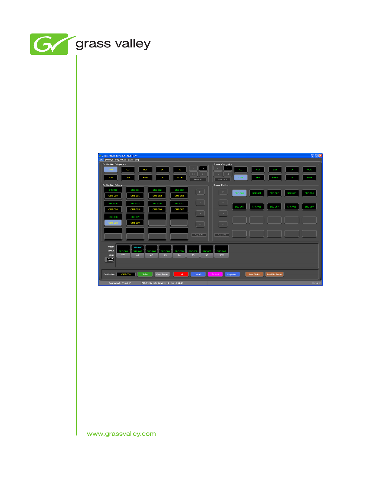
Multi-Level XY Soft Panel Main Screen Description . . . . . . . . . . . . . . . . . . . . . . . . 29
JUPITER Instruction Manual 5
Page 6

Contents
The Menu Bar . . . . . . . . . . . . . . . . . . . . . . . . . . . . . . . . . . . . . . . . . . . . . . . . . . . . . . 30
File Menu . . . . . . . . . . . . . . . . . . . . . . . . . . . . . . . . . . . . . . . . . . . . . . . . . . . . . . . . 30
Settings Menu . . . . . . . . . . . . . . . . . . . . . . . . . . . . . . . . . . . . . . . . . . . . . . . . . . . . 30
Sequences Menu . . . . . . . . . . . . . . . . . . . . . . . . . . . . . . . . . . . . . . . . . . . . . . . . . . 30
View Menu. . . . . . . . . . . . . . . . . . . . . . . . . . . . . . . . . . . . . . . . . . . . . . . . . . . . . . . 30
Help Menu . . . . . . . . . . . . . . . . . . . . . . . . . . . . . . . . . . . . . . . . . . . . . . . . . . . . . . . 31
Multi-Level XY Soft Panel Descriptions . . . . . . . . . . . . . . . . . . . . . . . . . . . . . . . . 31
Display Fields . . . . . . . . . . . . . . . . . . . . . . . . . . . . . . . . . . . . . . . . . . . . . . . . . . . . 31
Source and Destination Paging Buttons . . . . . . . . . . . . . . . . . . . . . . . . . . . . . . 32
Control Buttons . . . . . . . . . . . . . . . . . . . . . . . . . . . . . . . . . . . . . . . . . . . . . . . . . . . 32
Status Bar . . . . . . . . . . . . . . . . . . . . . . . . . . . . . . . . . . . . . . . . . . . . . . . . . . . . . . . . 33
Multi-Level XY Soft Panel Operating Procedures. . . . . . . . . . . . . . . . . . . . . . . . . . 34
Destination Selection / Status Check. . . . . . . . . . . . . . . . . . . . . . . . . . . . . . . . . . . 34
Source Selection (All Levels Take) . . . . . . . . . . . . . . . . . . . . . . . . . . . . . . . . . . . . . 35
Advise Option . . . . . . . . . . . . . . . . . . . . . . . . . . . . . . . . . . . . . . . . . . . . . . . . . . . . . . 36
Swap/Undo. . . . . . . . . . . . . . . . . . . . . . . . . . . . . . . . . . . . . . . . . . . . . . . . . . . . . . . . 37
Level Breakaways (Split Switching). . . . . . . . . . . . . . . . . . . . . . . . . . . . . . . . . . . . 37
Locking and Unlocking a Destination . . . . . . . . . . . . . . . . . . . . . . . . . . . . . . . . . . 38
Protecting or Un-protecting a Destination . . . . . . . . . . . . . . . . . . . . . . . . . . . . . . 38
Tool Tip Help . . . . . . . . . . . . . . . . . . . . . . . . . . . . . . . . . . . . . . . . . . . . . . . . . . . . . . 38
Sequence Operations . . . . . . . . . . . . . . . . . . . . . . . . . . . . . . . . . . . . . . . . . . . . . . . . . . 40
Local Sequences Screen Descriptions . . . . . . . . . . . . . . . . . . . . . . . . . . . . . . . . . . 40
Sequence Name . . . . . . . . . . . . . . . . . . . . . . . . . . . . . . . . . . . . . . . . . . . . . . . . . . . 41
Existing Sequences . . . . . . . . . . . . . . . . . . . . . . . . . . . . . . . . . . . . . . . . . . . . . . . . 42
Sequence List . . . . . . . . . . . . . . . . . . . . . . . . . . . . . . . . . . . . . . . . . . . . . . . . . . . . . 42
Sequence Commands . . . . . . . . . . . . . . . . . . . . . . . . . . . . . . . . . . . . . . . . . . . . . . 42
Creating a Local Sequence. . . . . . . . . . . . . . . . . . . . . . . . . . . . . . . . . . . . . . . . . . . . 42
Selecting an Existing Sequence . . . . . . . . . . . . . . . . . . . . . . . . . . . . . . . . . . . . . . 44
Removing an Existing Sequence . . . . . . . . . . . . . . . . . . . . . . . . . . . . . . . . . . . . . 44
Exporting an Existing Sequence . . . . . . . . . . . . . . . . . . . . . . . . . . . . . . . . . . . . . 45
Importing an Existing Sequence . . . . . . . . . . . . . . . . . . . . . . . . . . . . . . . . . . . . . 47
Jupiter System Sequences . . . . . . . . . . . . . . . . . . . . . . . . . . . . . . . . . . . . . . . . . . . . 48
Section 4 — VSD Introduction
Overview . . . . . . . . . . . . . . . . . . . . . . . . . . . . . . . . . . . . . . . . . . . . . . . . . . . . . . . . . . . . 51
Views . . . . . . . . . . . . . . . . . . . . . . . . . . . . . . . . . . . . . . . . . . . . . . . . . . . . . . . . . . . . . 51
Current VSD Limitations. . . . . . . . . . . . . . . . . . . . . . . . . . . . . . . . . . . . . . . . . . . . . . . 52
VSD Interface . . . . . . . . . . . . . . . . . . . . . . . . . . . . . . . . . . . . . . . . . . . . . . . . . . . . . . . . 52
The Menu Bar . . . . . . . . . . . . . . . . . . . . . . . . . . . . . . . . . . . . . . . . . . . . . . . . . . . . . . 53
File . . . . . . . . . . . . . . . . . . . . . . . . . . . . . . . . . . . . . . . . . . . . . . . . . . . . . . . . . . . . . . 53
Edit . . . . . . . . . . . . . . . . . . . . . . . . . . . . . . . . . . . . . . . . . . . . . . . . . . . . . . . . . . . . . 53
View . . . . . . . . . . . . . . . . . . . . . . . . . . . . . . . . . . . . . . . . . . . . . . . . . . . . . . . . . . . . 54
Tools . . . . . . . . . . . . . . . . . . . . . . . . . . . . . . . . . . . . . . . . . . . . . . . . . . . . . . . . . . . . 54
Help. . . . . . . . . . . . . . . . . . . . . . . . . . . . . . . . . . . . . . . . . . . . . . . . . . . . . . . . . . . . . 54
The Tool Bar. . . . . . . . . . . . . . . . . . . . . . . . . . . . . . . . . . . . . . . . . . . . . . . . . . . . . . . . 54
View Buttons . . . . . . . . . . . . . . . . . . . . . . . . . . . . . . . . . . . . . . . . . . . . . . . . . . . . . 54
Clipboard Buttons. . . . . . . . . . . . . . . . . . . . . . . . . . . . . . . . . . . . . . . . . . . . . . . . . 55
Search Field . . . . . . . . . . . . . . . . . . . . . . . . . . . . . . . . . . . . . . . . . . . . . . . . . . . . . . 55
Zoom% Field . . . . . . . . . . . . . . . . . . . . . . . . . . . . . . . . . . . . . . . . . . . . . . . . . . . . . 55
Column Width Adjustments . . . . . . . . . . . . . . . . . . . . . . . . . . . . . . . . . . . . . . . . 55
Force Unlock Button . . . . . . . . . . . . . . . . . . . . . . . . . . . . . . . . . . . . . . . . . . . . . . . 55
The View System Status Area. . . . . . . . . . . . . . . . . . . . . . . . . . . . . . . . . . . . . . . . . 55
6 JUPITER Instruction Manual
Page 7

Contents
The View Selection Area. . . . . . . . . . . . . . . . . . . . . . . . . . . . . . . . . . . . . . . . . . . . . . 56
The Connection Information Area . . . . . . . . . . . . . . . . . . . . . . . . . . . . . . . . . . . . . 56
Interface Views . . . . . . . . . . . . . . . . . . . . . . . . . . . . . . . . . . . . . . . . . . . . . . . . . . . . . . . 57
Destinations View . . . . . . . . . . . . . . . . . . . . . . . . . . . . . . . . . . . . . . . . . . . . . . . . . . . 57
Sources View . . . . . . . . . . . . . . . . . . . . . . . . . . . . . . . . . . . . . . . . . . . . . . . . . . . . . . . 57
Control Boards View. . . . . . . . . . . . . . . . . . . . . . . . . . . . . . . . . . . . . . . . . . . . . . . . . 58
Tie Lines View . . . . . . . . . . . . . . . . . . . . . . . . . . . . . . . . . . . . . . . . . . . . . . . . . . . . . . 59
The Router Connection Settings Window . . . . . . . . . . . . . . . . . . . . . . . . . . . . . . . 60
The Open Custom View Window. . . . . . . . . . . . . . . . . . . . . . . . . . . . . . . . . . . . . . 61
The Options Window . . . . . . . . . . . . . . . . . . . . . . . . . . . . . . . . . . . . . . . . . . . . . . . . 61
Section Headings . . . . . . . . . . . . . . . . . . . . . . . . . . . . . . . . . . . . . . . . . . . . . . . . . . 62
Use of Color . . . . . . . . . . . . . . . . . . . . . . . . . . . . . . . . . . . . . . . . . . . . . . . . . . . . . . . . 63
Requiring a Password to Change Settings on the Options Dialog . . . . . . . . . 64
Hot Keys . . . . . . . . . . . . . . . . . . . . . . . . . . . . . . . . . . . . . . . . . . . . . . . . . . . . . . . . . . . 66
Section 5 — VSD Installation
Distribution . . . . . . . . . . . . . . . . . . . . . . . . . . . . . . . . . . . . . . . . . . . . . . . . . . . . . . . . . . 67
Requirements . . . . . . . . . . . . . . . . . . . . . . . . . . . . . . . . . . . . . . . . . . . . . . . . . . . . . . . 67
PC Display Requirements. . . . . . . . . . . . . . . . . . . . . . . . . . . . . . . . . . . . . . . . . . . 67
.NET Software Requirements. . . . . . . . . . . . . . . . . . . . . . . . . . . . . . . . . . . . . . . . 68
Installing VSD Using the VSD Installer . . . . . . . . . . . . . . . . . . . . . . . . . . . . . . . . . . . 69
Uninstall Process . . . . . . . . . . . . . . . . . . . . . . . . . . . . . . . . . . . . . . . . . . . . . . . . . . . . . . 72
Removing the VSD . . . . . . . . . . . . . . . . . . . . . . . . . . . . . . . . . . . . . . . . . . . . . . . . . . 72
Using the Add Remove Program Feature . . . . . . . . . . . . . . . . . . . . . . . . . . . . . 72
Using the Installation program . . . . . . . . . . . . . . . . . . . . . . . . . . . . . . . . . . . . . . 72
Configuration Process . . . . . . . . . . . . . . . . . . . . . . . . . . . . . . . . . . . . . . . . . . . . . . . . . 75
VSD PC IP Settings . . . . . . . . . . . . . . . . . . . . . . . . . . . . . . . . . . . . . . . . . . . . . . . . . . 75
Connecting to the Network . . . . . . . . . . . . . . . . . . . . . . . . . . . . . . . . . . . . . . . . . 75
VSD Application Settings. . . . . . . . . . . . . . . . . . . . . . . . . . . . . . . . . . . . . . . . . . . . . 75
User Preferences. . . . . . . . . . . . . . . . . . . . . . . . . . . . . . . . . . . . . . . . . . . . . . . . . . . 78
Section 6 — VSD Procedures
VSD Procedures. . . . . . . . . . . . . . . . . . . . . . . . . . . . . . . . . . . . . . . . . . . . . . . . . . . . . . . 81
Creating a View . . . . . . . . . . . . . . . . . . . . . . . . . . . . . . . . . . . . . . . . . . . . . . . . . . . . . 81
Closing a View . . . . . . . . . . . . . . . . . . . . . . . . . . . . . . . . . . . . . . . . . . . . . . . . . . . . . . 82
Opening a View . . . . . . . . . . . . . . . . . . . . . . . . . . . . . . . . . . . . . . . . . . . . . . . . . . . . . 82
Copying and Pasting a Row. . . . . . . . . . . . . . . . . . . . . . . . . . . . . . . . . . . . . . . . . . . 83
Deleting a Row. . . . . . . . . . . . . . . . . . . . . . . . . . . . . . . . . . . . . . . . . . . . . . . . . . . . . . 84
Using the Search Field . . . . . . . . . . . . . . . . . . . . . . . . . . . . . . . . . . . . . . . . . . . . . . . 85
Using the Hide Mode . . . . . . . . . . . . . . . . . . . . . . . . . . . . . . . . . . . . . . . . . . . . . . . . 85
Adjusting the Column Width . . . . . . . . . . . . . . . . . . . . . . . . . . . . . . . . . . . . . . . . . 86
Adjusting a Single Column . . . . . . . . . . . . . . . . . . . . . . . . . . . . . . . . . . . . . . . . . 86
Seeing All the Columns. . . . . . . . . . . . . . . . . . . . . . . . . . . . . . . . . . . . . . . . . . . . . 87
Seeing All of the Content . . . . . . . . . . . . . . . . . . . . . . . . . . . . . . . . . . . . . . . . . . . 88
Changing the Zoom Percentage . . . . . . . . . . . . . . . . . . . . . . . . . . . . . . . . . . . . . . . 88
Setting the Zoom% to all Views of the Same Type . . . . . . . . . . . . . . . . . . . . . . 89
Using the Force Unlock Option . . . . . . . . . . . . . . . . . . . . . . . . . . . . . . . . . . . . . . 90
Clearing Tie Lines . . . . . . . . . . . . . . . . . . . . . . . . . . . . . . . . . . . . . . . . . . . . . . . . . 90
JUPITER Instruction Manual 7
Page 8

Contents
Index. . . . . . . . . . . . . . . . . . . . . . . . . . . . . . . . . . . . . . . . . . . . . . . . . . . . . . . . . . . . . . . . . . . . . . 95
8 JUPITER Instruction Manual
Page 9
Section 1
CM-4000 System Controller
IP switch
Jupiter
File Server
IP: “192.168.253.10”
IP:
“192.168.253.1”
Gateway
Facility LAN
Jupiter LAN
Jupiter LAN
IP:
“192.168.1.1”
PC IP: "192.168.1.101"
Multi-Level Device ID: “02”
Gateway: "192.168.1.1"
Multi-Level XY GUI PC
PC IP: “192.168.253.30”
Multi-Level XY GUI Device ID: "01"
Crosspoint
Bus
GV matrix router
Remote
Basic XY GUI PC
8536_28
Introduction and Installation
Overview
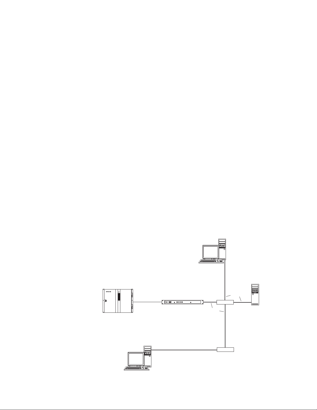
The Jupiter Basic XY and Multi-Level XY Soft Panels are applications that
are used to control a matrix router switcher. These Soft Panel applications
run on the English version of the Windows XP Professional operating
system. The computers that are running these Soft Panel applications must
be able to communicate, through a network, with a Jupiter CM-4000
System Controller running AccuSwitch (See
Control board supports up to 64 devices, which can include any combination of hardware and soft panels.
Figure 1). Each AccuSwitch
Note The number of entries in the Control Panel’s Input, Output, Level, Sequence
Figure 1. Jupiter System with Basic XY and Multi-level XY Soft Panels
and Override sets will have an effect on the System Controller’s memory.
JUPITER AccuSwitch Soft Panels and Visual Status Display Instruction Manual 1
Page 10

Section 1 — Introduction and Installation
Software Installation
Requirements
PC Requirements
Verify that the PC has the following minimum requirements before
installing the AccuSwitch applications:
• Microsoft.NET 3.5 framework software (500 MB of disk space required)
• Windows XP Pro SP2 (English version)
• 2 GHz Pentium processor
•1 GB of RAM
• Minimum of 13 MB disk space for each application
A minimum resolution of 1280 X 1024 and 32 -bit color PC monitor setting
is recommended for proper display of the Soft Panel screens. The font size
selected in the Appearance option on the Display Properties dialog (Con
trol Panels> Display> Appearance: Font size drop-down list) should be set
to Normal. Selecting either the Large or the Extra Large Fonts option will
cause application display problems.
-
.NET Software Requirements
The PC that is running a Soft Panel application must have Microsoft’s .NET
Framework software installed. The .NET Framework version 3.5 SP1 can be
installed on Windows XP Pro SP2. Other Microsoft-specified requirements
are listed in
Note Grass Valley only supports the English version of Windows XP SP2 for the
Table 1. System Requirements for Installing .NET Framework 3.5
Processor Minimum 400 megahertz (MHz) Pentium processor
RAM: Minimum: 96 megabytes (MB)
Hard Disk Up to 500 MB of available space may be required.
Installation Drive The .NET Framework 3.5 default installation location is the PC’s system drive (the
Ta bl e 1.
Basic XY, Multi-Level XY, and Visual Status Display.
Recommended: 1 gigahertz (GHz) Pentium processor
Recommended: 256 MB
drive that boots your system). Ensure at least 500 MB is available on the system drive.
2 JUPITER AccuSwitch Soft Panels and Visual Status Display Instruction Manual
Page 11
Installing the Soft Panel Application
The following instructions show the steps that are needed to install both
soft Panel applications. The Basic XY Soft Panel screens are used as exam
ples. However, the Multi-Level XY instructions steps are identical to the
Basic XY instructions.
Follow these steps to start the Soft Panel application installation process:
1. Insert the supplied software CDROM into the computer’s CD Drive
and follow the prompts.
Note The CD should automatically start the installation process. If not, browse to
the CD, using Window Explorer, and then click the setup.exe icon.
2. If this is an Initial installation, you may see a message asking if you
want to install Microsoft .NET Framework. If so, select the
(The 3.5 SP1 version of .NET is located on the Soft Panel Installation
CD.)
Depending on the version of the computer’s OS, the system may reboot
automatically during this process.
Software Installation
-
Yes button.
Note After an auto reboot, it may take several minutes for the system to display the
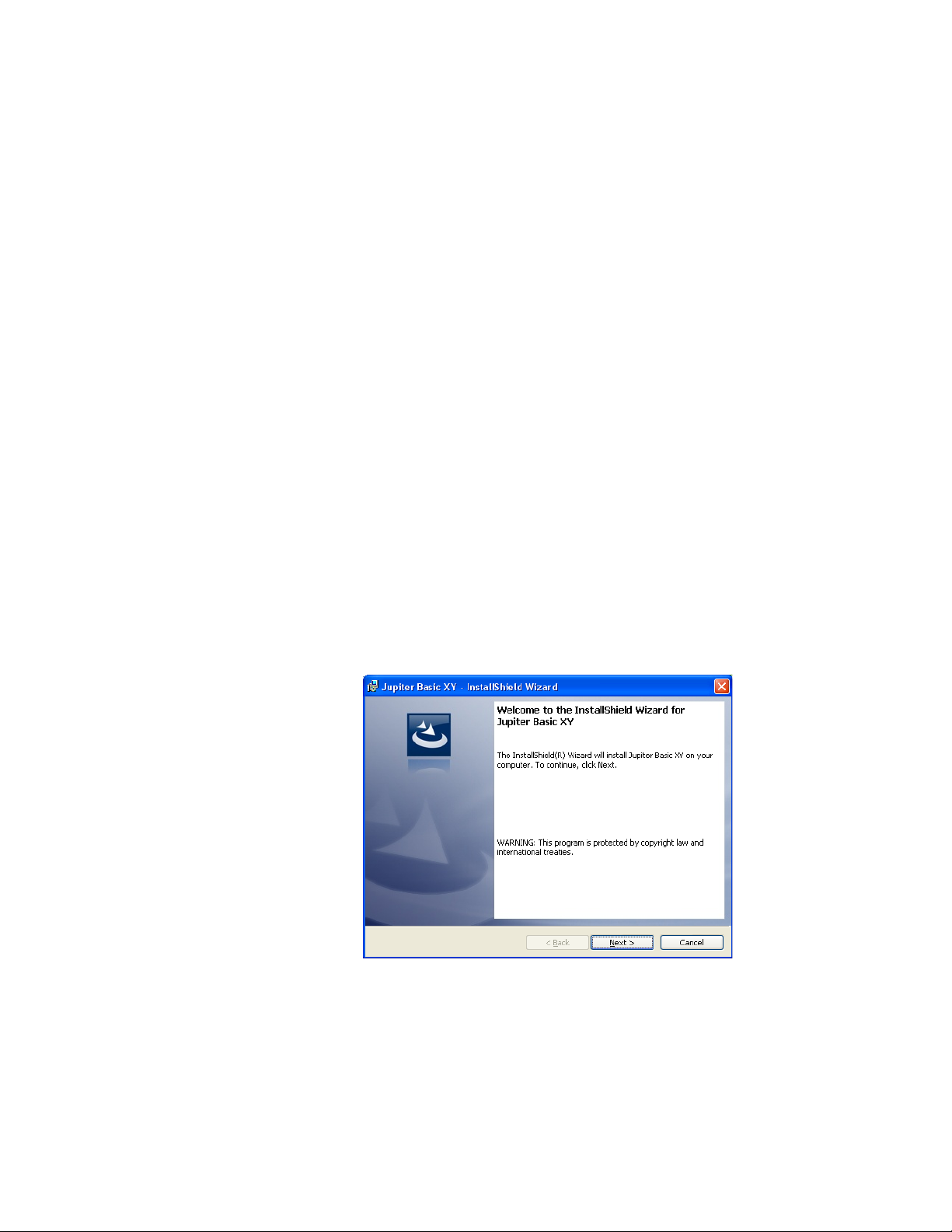
Soft Panel installation welcome screen.
The Soft Panel Welcome screen will then appear (Figure 2).
Figure 2. Soft Panel Installer Welcome Screen
3. Click the Next> button to begin the installation process. The License
Agreement screen will then appear (Figure 3).
JUPITER AccuSwitch Soft Panels and Visual Status Display Instruction Manual 3
Page 12
Section 1 — Introduction and Installation
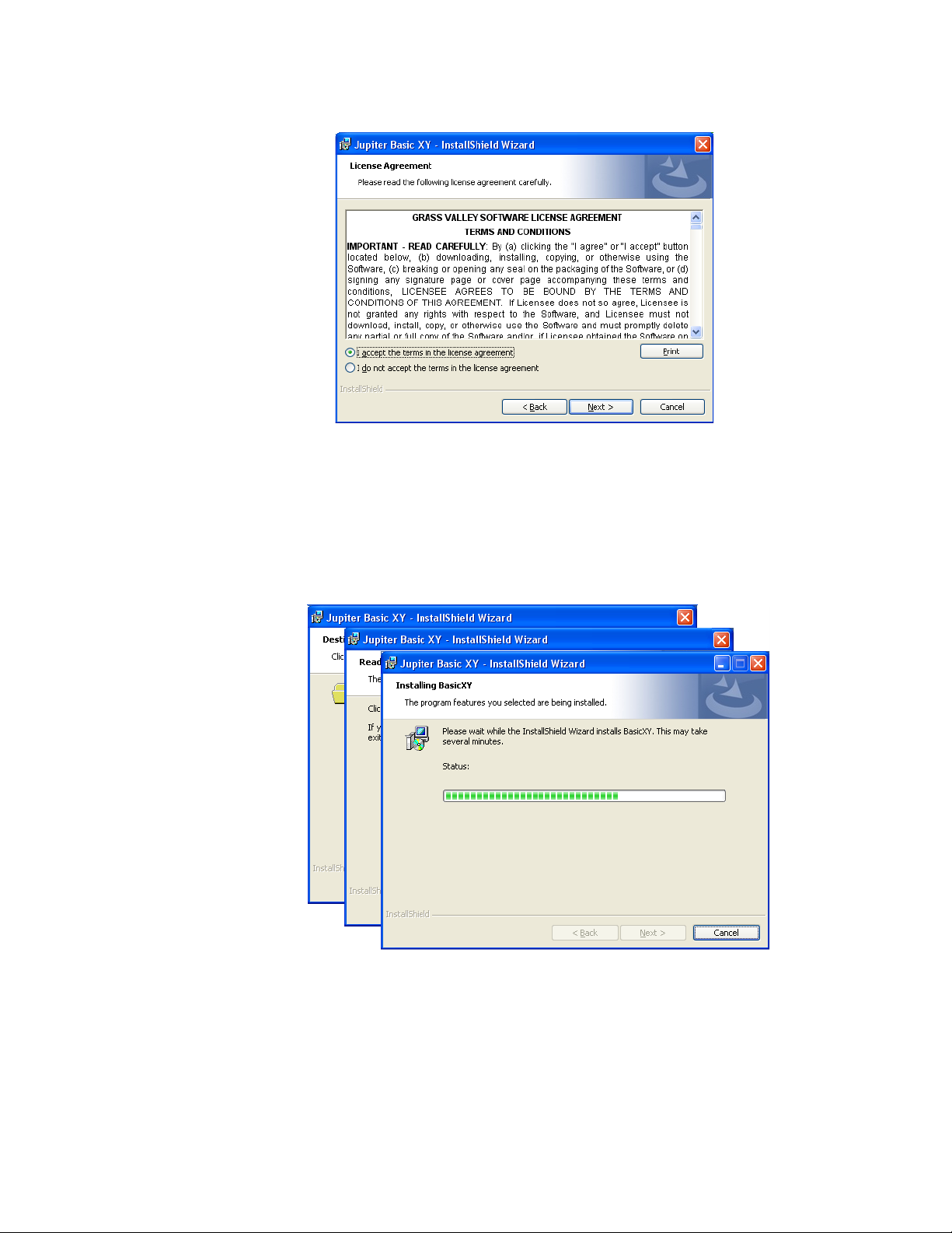
Figure 3. Soft Panel Installer License Agreement Screen
4. Click the I accept the terms in the License agreement radio button.
5. Click the Next> button to begin the installation process.
6. Follow the instructions on the following installation screens; click the
Next button as needed (Figure 4).
Figure 4. Soft Panel Installation Screens
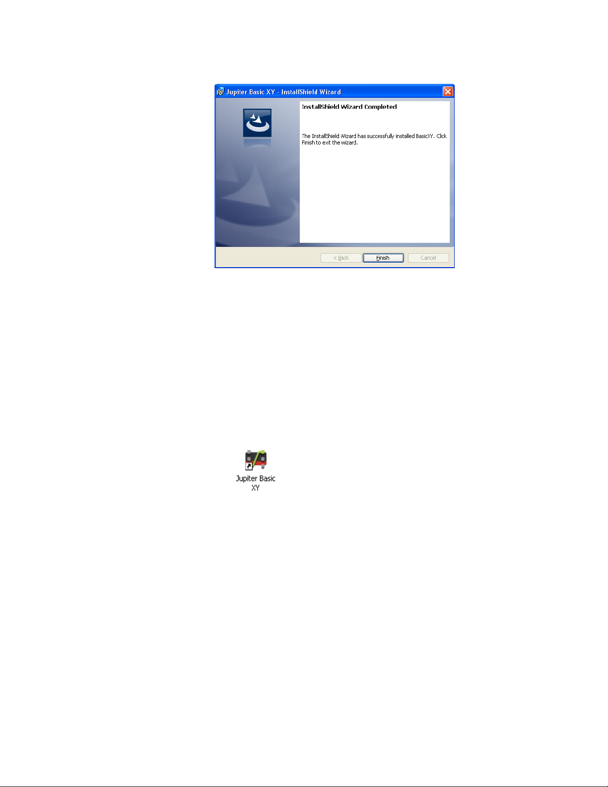
7. The InstallShield Wizard Completed screen will appear when the
installation process is finished (Figure 5).
4 JUPITER AccuSwitch Soft Panels and Visual Status Display Instruction Manual
Page 13
Software Installation
Figure 5. Installation Completed Screen
8. Click the Finish button. The Installation application will then close.
Soft Panel Desktop Icon
As part of the installation process a Soft Panel shortcut, for the type of soft
panel that was installed (Basic XY or Multi-Level XY), will be displayed on
your PC’s desktop (
installed soft panel. The Soft panel must be configured to meet your needs
Note See the Configuration section below for the configuration steps.
Figure 6. The Soft Panels Shortcut Example
Note The Soft Panel application still needs to be configured with your Jupiter
AccuSwitch system before it will become operational.
Figure 6). Clicking this shortcut will launch the
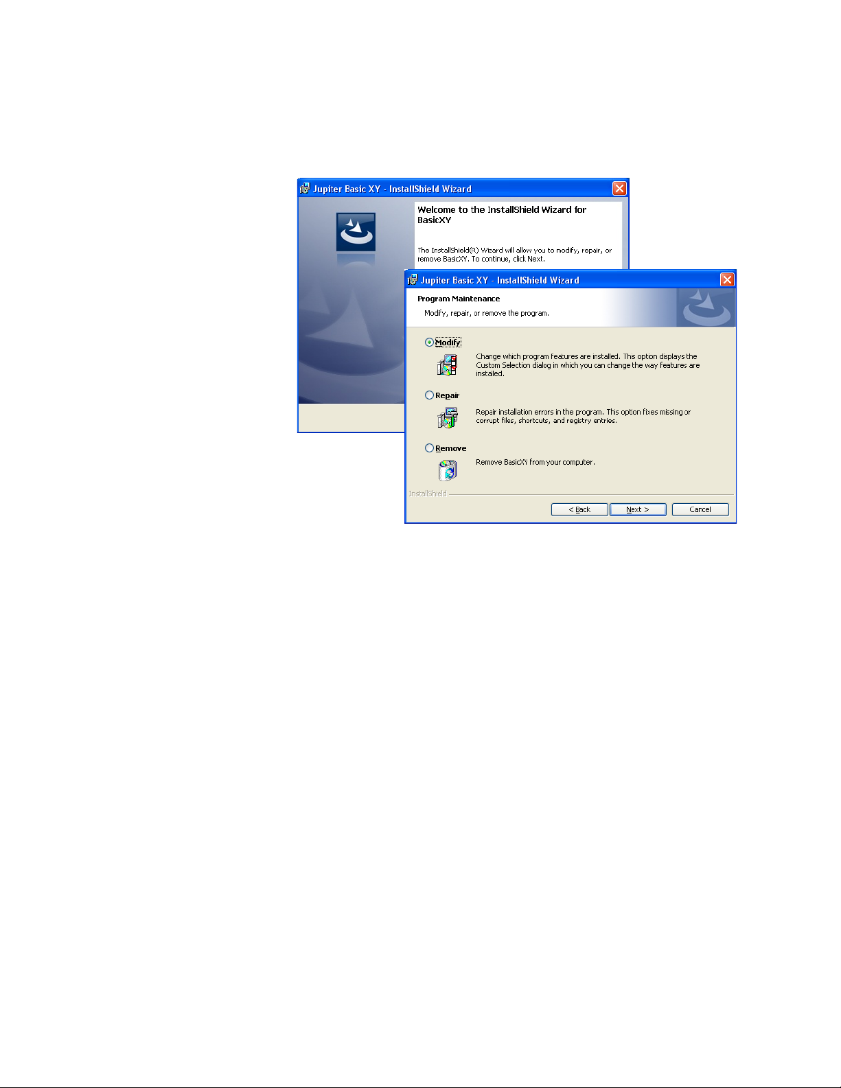
Performing Maintenance on the Soft Panel Application
When a Soft Panel application already exists on the PC when the installation program is run:
• If the version is older than what is being installed, then the installation wizard will ask to perform an update.
• If the version is the same as what is being installed, then the
Welcome screen displays a Modify, Repair, Remove message.
JUPITER AccuSwitch Soft Panels and Visual Status Display Instruction Manual 5
Page 14
Section 1 — Introduction and Installation
Clicking the Next> button allows you to make changes to the Soft Panel
installation (
Figure 7. Installation Modify, Repair, Remove Screen
Figure 7).
Select the preferred task and then click the Next> button.
6 JUPITER AccuSwitch Soft Panels and Visual Status Display Instruction Manual
Page 15

Configuration
Soft Panel PC IP Settings
Connecting to the Network
Configuration
The PC, on which the Soft Panel application is installed, must be configured
to communicate with the Jupiter AccuSwitch Controller. Consult with your
Network administrator for this information.
The Soft panel and the VSD connect to the network using one of two ports.
These ports are either:
•Port 420
• A port number that is the Device ID added to 50000. For example, if the
Device ID is 21, the port number would be 50021.
Note If the GUI panel is behind a firewall, the ports listed above will need to be
opened for the Soft panel and VSD to communicate with the AccuSwitch
Control module.
Router Connection Settings
During the following steps, you will need to know the IP address of the
primary AccuSwitch Controller (and the secondary, if it is installed) that
will be associated with the Soft Panel and the PC’s IP address. Use the
Jupiter File Server JNS Control Center application’s Board Info tab to deter
mine the AccuSwitch Controller IP address (the Control Center application
is described in the Jupiter CM-4000 Installation and Operating manual).
Note Consult with your Network administrator if you do not know the network
values to enter.
Follow these steps to set the Router Connection settings:
1. Launch the Soft Panel application. This will display the main Soft Panel
screen (Figure 8).
-
JUPITER AccuSwitch Soft Panels and Visual Status Display Instruction Manual 7
Page 16
Section 1 — Introduction and Installation
Figure 8. Basic XY Soft Panel Startup Display Example
2. Select Route Connection from the File menu (File> Route Connection).
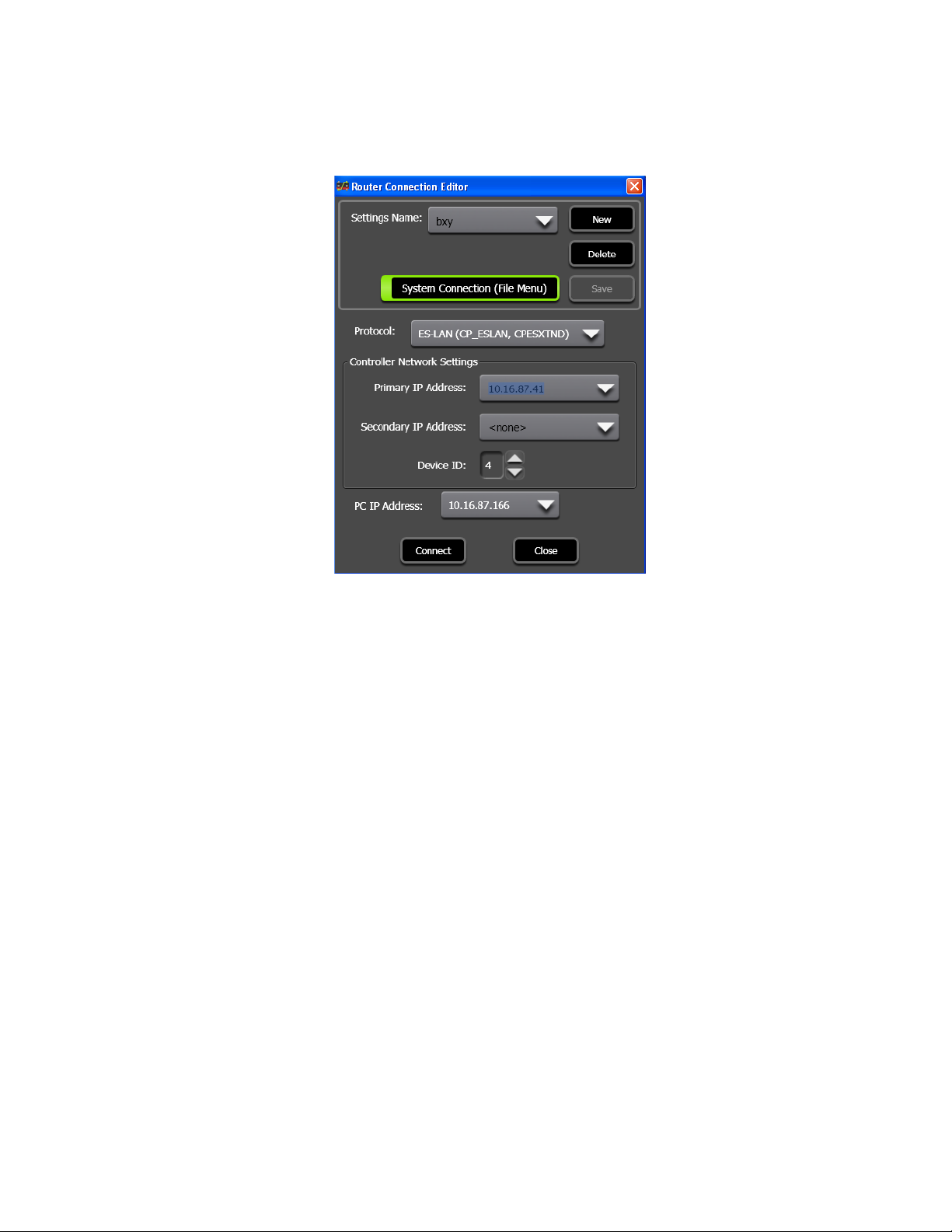
The Router Connection Editor dialog will then appear.
3. Enter the name for the setting in the Setting Name field. The Setting
Name field can be changed when configuring a new connection, before
the
Save button has been selected.
Note The maximum length of a Settings name is 16 characters.
4. Click the System Connection (file Menu) button to enable the System
Connections option and save the connection to the File menu. This menu
option provides a list of available connections that have been saved and
can be used to connect to a server.
5. Select the Protocol from the list.
8 JUPITER AccuSwitch Soft Panels and Visual Status Display Instruction Manual
Page 17
Configuration
Note Currently, the only selectable option for the Protocol list is ES-LAN.
Figure 9. Router Connection Editor Dialog
Controller network Settings
1. Enter the IP address of the AccuSwitch Controller that is associated
with this Soft Panel in the Primary IP Address field.
2. Enter the IP address of the secondary AccuSwitch Controller in the
Secondary IP Address field. Leave the field blank if there is not a
secondary controller.
3. Enter a number between 1 and 64 for the Device ID field. This number
must be unique from all panels that are associated with the same
AccuSwitch Controller. The Device ID is also entered on the MPK
Devices table, as described below in the MPK Table Entries section.
Note The Device ID number selected here corresponds to the MPK table Address
entry that uses two digit leading-zero numbers (01-09).
4. Select the IP address for the PCs NIC card from the PC IP Address drop-
down list, if it is not already selected (See Soft Panel PC IP Settings on
page 7).
Note If you have more than one NIC card, consult your IT department to determine
which IP Address will be able to communicate with the Jupiter Network
(AccuSwitch control board).
5. Click the Connect button.
JUPITER AccuSwitch Soft Panels and Visual Status Display Instruction Manual 9
Page 18
Section 1 — Introduction and Installation
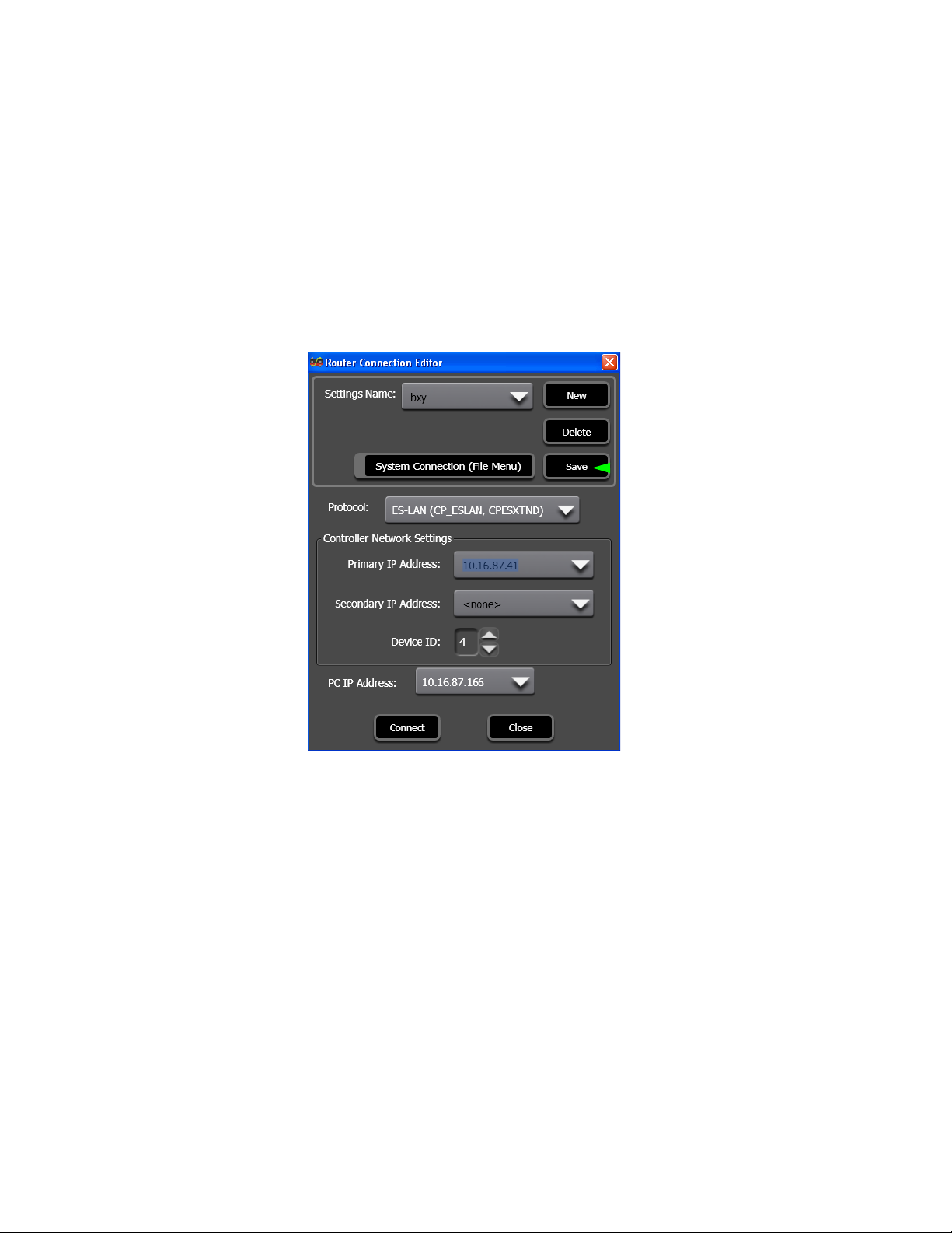
The Save
button
Saving the Device Settings
Save the settings by selecting the Save Settings option from the File menu
(File> Save Settings). The Save Device Settings dialog will then appear.
Follow these steps to save the device settings:
1. Create a name for the settings file. For example, the Panel Name “ES-
LAN2” could be used.
2. Click the Save button (Figure 10).
Figure 10. The Save Button
The current connection settings are then saved to the "NetworkSettings.xml" file, which is located in the installation directory for the specific
control panel. For example, C:\Program Files\Thomson\Jupiter Basic XY
would be the location for the settings for the Basic XY panel.
Clicking the Close Button Without Saving the Settings
The Save Network Connection(s) dialog (Figure 11 on page 11) will appear
if a new connection has been created or if changes have been made to an
existing connection and then the
the
Save button.
The Save Network Connection(s) dialog will prompt you to save the
changes.
Close button is clicked before first clicking
10 JUPITER AccuSwitch Soft Panels and Visual Status Display Instruction Manual
Page 19
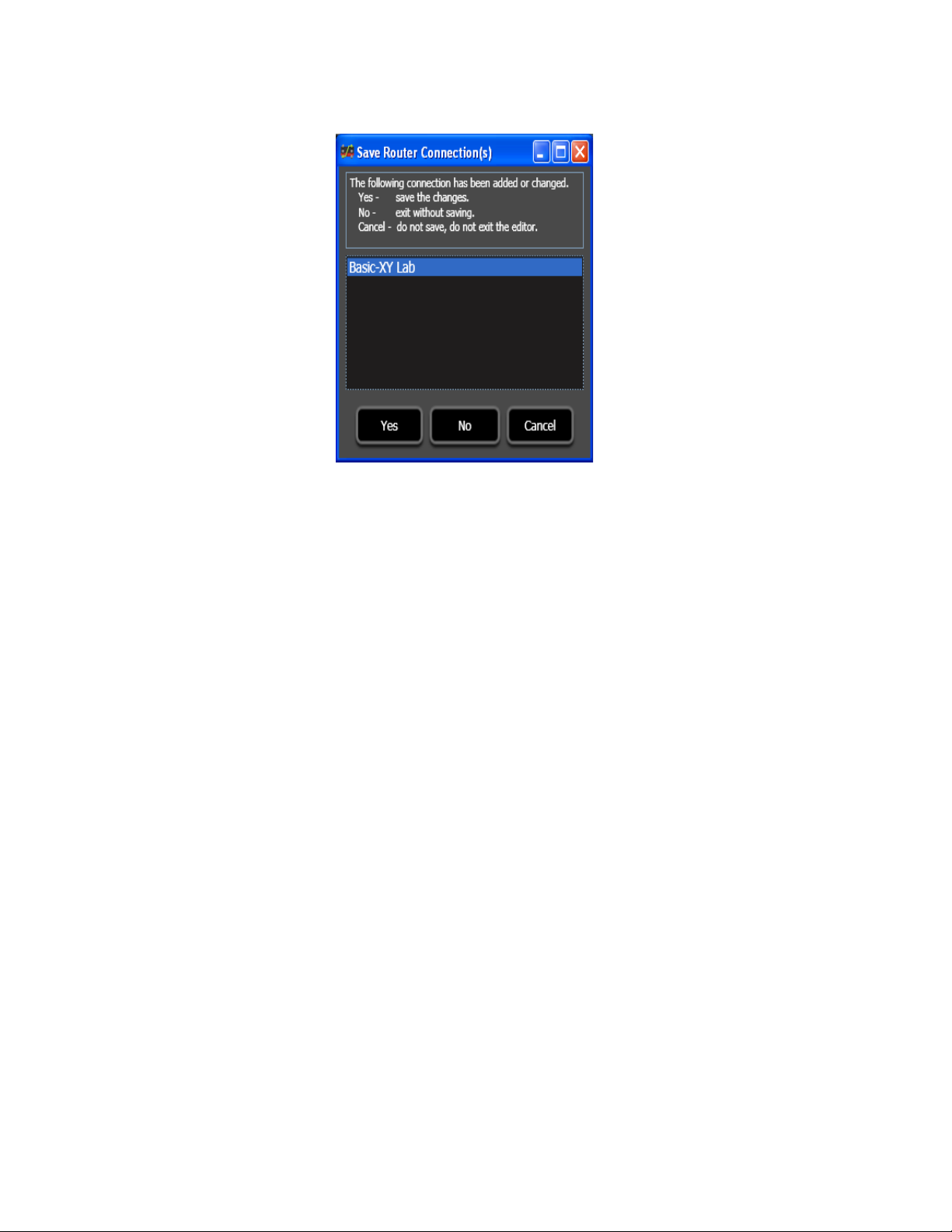
Figure 11. The Save Network Connections) Dialog
• Click the Yes button to save the changes.
Configuration
• Click the
the Router Connection Editor dialog without saving the changes. You
will no longer be prompted to save changes when you exit the program.
• Click the
and return to the Router Connection Editor dialog. However, no
changes will be saved.
No button to close the Save Router Connection(s) dialog and
Cancel button to close the Save Network Connection(s) dialog
Clicking the Connect Button Without Saving the Settings
The application will attempt to reconnect using the new or changed connection settings if you click the Connect button on the Router Connection
Editor dialog. This attempt will happen whether the changes were saved or
not. These settings are temporary and will be lost if the application is closed
and the setting changes were not saved.
Assigning a Function Key
The Multi-Level XY Soft panel application allows you to assign a Function
key for the
Takes. This is not an option for the Basic XY soft panel.
Take button. The function key could then be used to perform
JUPITER AccuSwitch Soft Panels and Visual Status Display Instruction Manual 11
Page 20
Section 1 — Introduction and Installation
Follow these steps to assign a function key:
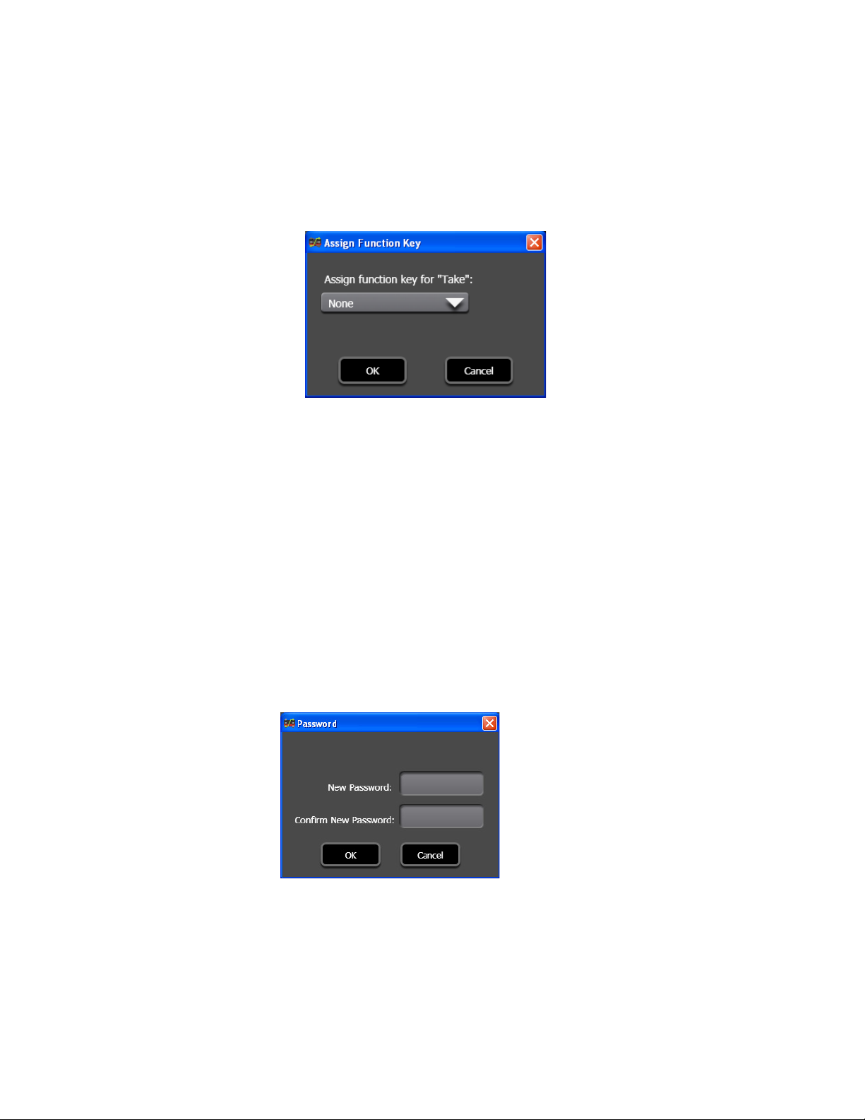
1. Select the Assign Function Key.... option from the Settings menu
(Settings> Assign Function Key....). The Assign Function Key dialog will
then appear.
Figure 12. Assign Function Key Dialog
2. Select a Function key from the drop-down list. Any function key
between F1 and F12 can be assigned.
3. Click the OK button to save the selection.
Setting Password Protection
A password can be used to protect the settings file if that is your preference,
Figure 13. This setting is optional.
see
Follow these steps to set password protection:
1. Select Change/Set Password from the Settings menu (Settings>
Change/Set Password...).
Figure 13. Password Dialog
2. Enter a password in the New Password field. Passwords are case-
sensitive and must be from 1 to 20 characters in length. Any character
can be used, including spaces.
3. Re-enter the password entered in the New Password field into the
Confirm New Password field.
12 JUPITER AccuSwitch Soft Panels and Visual Status Display Instruction Manual
Page 21
4. Click the OK button to save the changes.
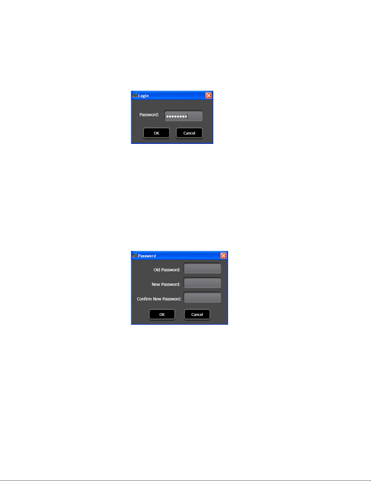
Once a password has been set, you will need to log in before you can make
changes to the Soft Panel settings, see
Figure 14. Login Dialog, if Password Protected
Changing the Password
Once a password has been set and you want to create a new password, you
will need to enter the original password and then the new password.
Configuration
Figure 14.
Follow these steps to change the password:
1. Select Change/Set Password from the Settings menu (Settings>
Change/Set Password...). The Password dialog will then appear.
Figure 15. Password Dialog
2. Enter the previously saved password in the Old password field.
3. Enter a new password in the New Password field. Passwords are case-
sensitive and must be from 1 to 20 characters. Any character can be
used, including spaces.
4. Re-enter the password entered in the New Password field into the
Confirm New Password field.
5. Click the OK button to save the changes.
JUPITER AccuSwitch Soft Panels and Visual Status Display Instruction Manual 13
Page 22
Section 1 — Introduction and Installation
Selected
Option Button
Display Field
View Menu
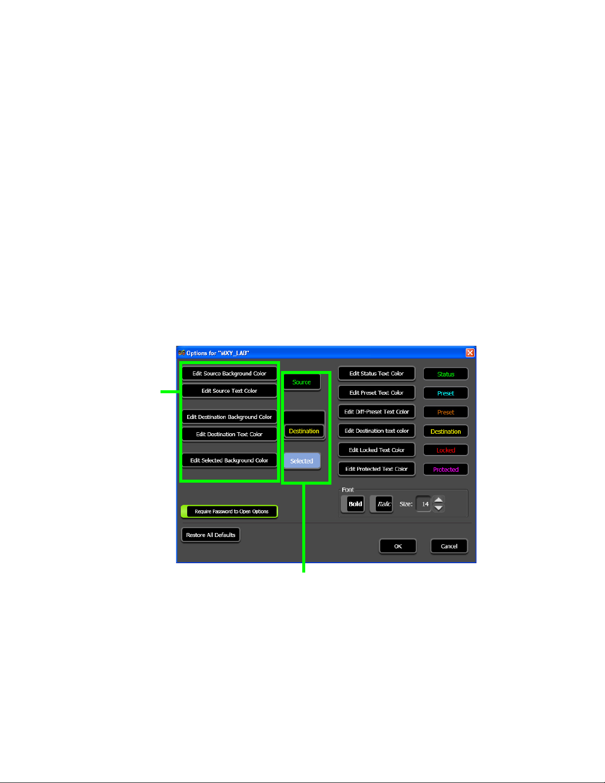
Currently the only available selection in the View menu is Options.
Options
The panel’s optional settings are contained in the Options dialog. The Soft
Panel’s background colors, font’s colors, styles, and size can be changed to
meet your needs. The Soft Panel application’s default colors are listed
below in the
These options are now associated with a connection, which means each
connection could have different colors and settings. The intent of this
optional change in color and settings is to make it easier to identify each
connection that you are using.
Follow these steps to modify the options for a soft panel and VSD:
1. Select View> Options... from the Menu bar. The Options screen will
then appear (Figure 16).
Default Colors section.
Figure 16. Options Screen
14 JUPITER AccuSwitch Soft Panels and Visual Status Display Instruction Manual
Page 23
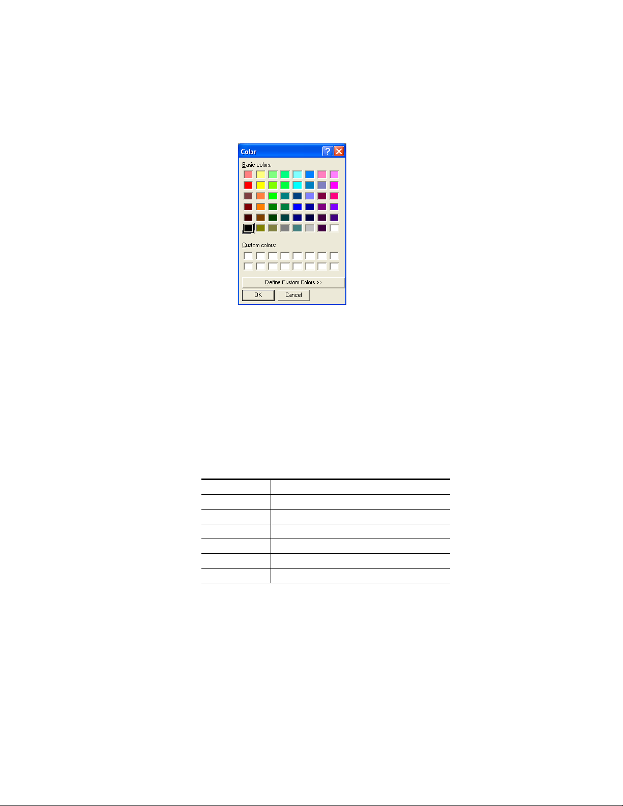
Configuration
2. Clicking any one of the Option buttons, that start with “Pick. . .,”will
open the Color dialog (Figure 17). This color dialog allows you to use
standard windows colors or you can define custom colors.
Figure 17. Options Color Selection Dialog
3. Selecting a color and then clicking the OK button, in the Color dialog will
change the option’s example display field to that color.
4. Controls are also available that allow selecting the font size, bold, and
italic attributes (see Figure 16 on page 14).
Default Colors
The colors listed below are the default color settings.
Table 2. Default Colors
Color Function
Green Current Source/Status
Magenta Protect
Red Lock
Yellow Destination
Cyan Preset/Next source
Amber Misc selections.
Note If a level on the Multi-Level XY is different from the first level, it will be dis-
played in Amber while on the Preset line; however, the Level will be displayed
in Green once it is on the Status line.
Requiring a Password to Change Settings on the Options Dialog
You can limit the ability to change the settings on the Options dialog by
requiring a password to make changes.
JUPITER AccuSwitch Soft Panels and Visual Status Display Instruction Manual 15
Page 24
Section 1 — Introduction and Installation
Note This required password is the password that was set for the entire control
panel. See Setting Password Protection on page 12 for more information.
Follow these steps to make a password required:
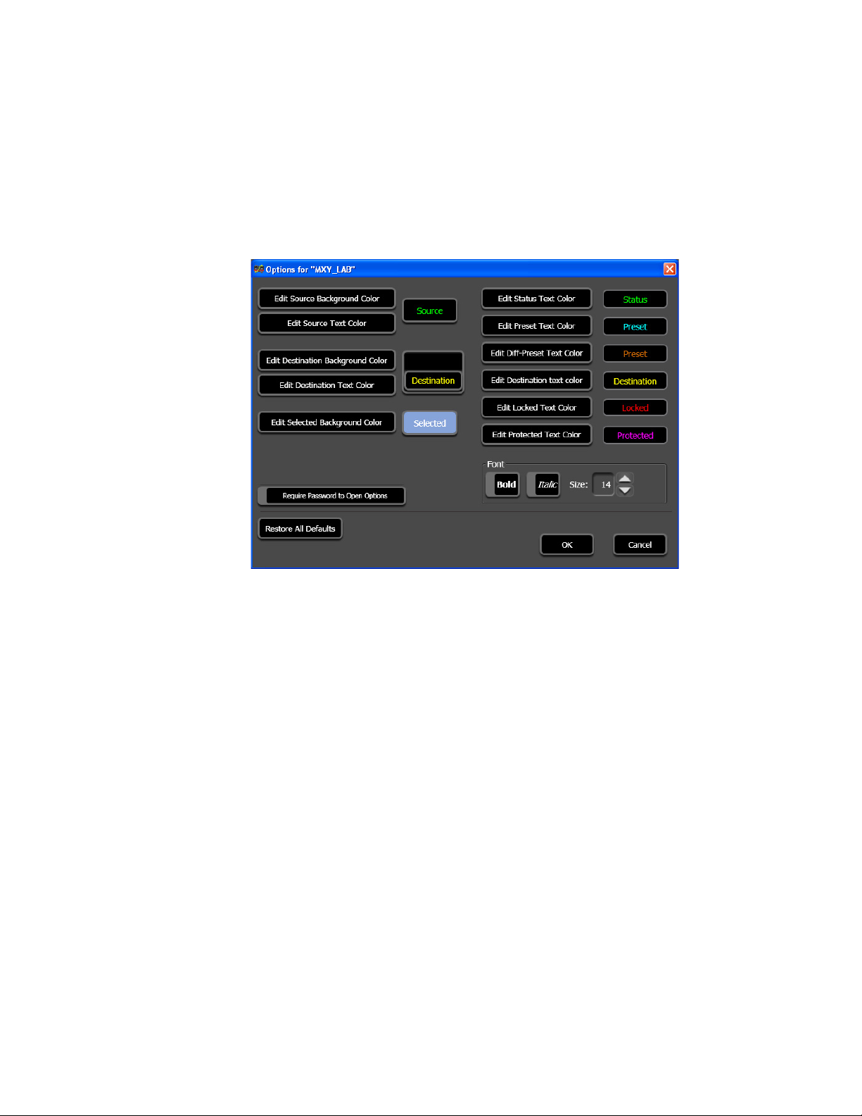
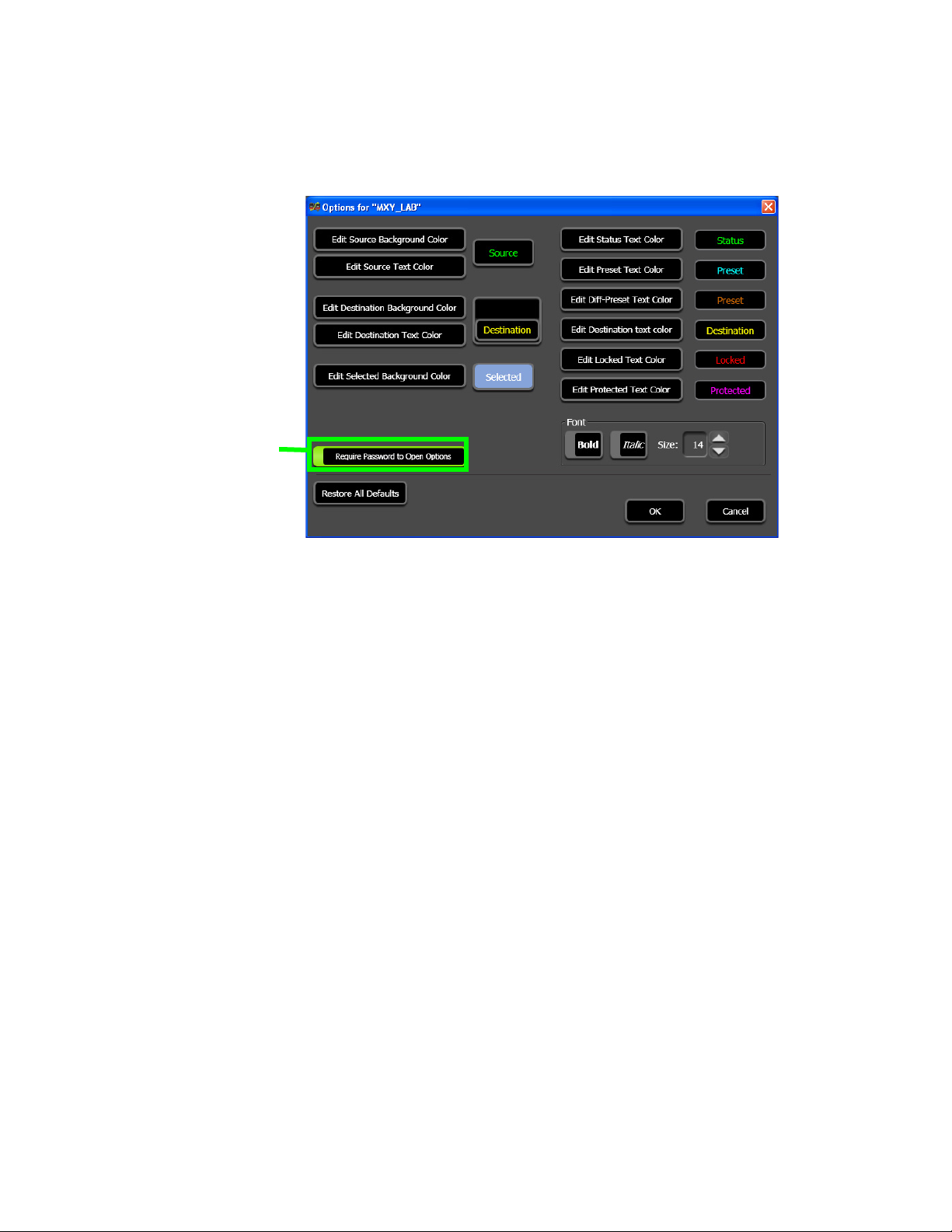
1. Select View> Options... from the Menu bar. The Options screen will
then appear (Figure 18).
Figure 18. Options Screen
16 JUPITER AccuSwitch Soft Panels and Visual Status Display Instruction Manual
Page 25
Configuration
Require Password to Open
Options Button
2. Click the Require Password to Open Options button; the button will now be
highlighted (Figure 19).
Figure 19. Options Screen
A password will now need to be entered into the Login dialog open the
Options dialog (
Figure 14 on page 13).
JUPITER AccuSwitch Soft Panels and Visual Status Display Instruction Manual 17
Page 26

Section 1 — Introduction and Installation
Jupiter File Server Settings
The following overview assumes that the reader is familiar with the Jupiter
Facility Control System. If not, please refer to the Jupiter CM-4000 Installa
tion and Operation manual.
MPK Table Entries
Although the Soft Panel and VSD applications are not actually an MPKtype panel (it does not use the Message Per Keystroke protocol), the MPK
table is used for configuration purposes.
MPK Device - Enter a name, up to eight characters in length, for each Soft
Panel. This name must be unique system-wide.
Type - Select type “CP-ESLAN” on the pull-down menu. Select
“CPESXTND” for use with 98 categories.
Expansion - Leave unchecked not used for Soft Panels.
Password - Enter 90-99 in the Password column to enable the Force Unlock /
Unprotect option. Devices can now be configured to force unlock and force
un-protect any destination regardless of what panel locked or protected it.
See the 7.8.1 version of the Jupiter Control System Release Notes (part #
071827511) for more information.
Board - Enter the name of AccuSwitch Controller associated with this Soft
Panel. The source of this name is the Network Description table.
-
Port - This field is not used for Soft Panels.
Address - Enter the panel address from 01 to 64. The address must be unique
for panels that are associated with the same AccuSwitch Controller. This
number is referred to as the “Device ID” on the Soft Panel “Devices> Set
tings” menu.
Input Set - Enter the name of CP Input Set to be assigned to this panel. The
usual practice is to have one CP Input Set, which contains the names of all
sources, be applied to all panels. However, a special CP Input Sets that list
only selected sources could be created. Such a set could be used to prevent
certain panels from selecting specific sources.
Note When entering the information for the VSD, you want all inputs, outputs, and
levels.
In Panel - This column is not used for Soft Panels.
Out Set - Enter the name of the CP Output Set to be assigned to this panel. If
the entry is an actual CP Output Set, then the control panel will be able to
control all the destinations listed in that Set. Depending on the contents of
the set, this would allow for full-matrix or multi-bus control. The source of
the destination name is the Switcher Output table.
-
18 JUPITER AccuSwitch Soft Panels and Visual Status Display Instruction Manual
Page 27

Out Panel - This column is not used for Soft Panels.
Level Set - Select the CP Level Set name.
Override - This column is not used for Soft Panels.
Sequence - A Sequence Set can be created and named, which, when assigned
to a panel, makes the sequences in that set available on that panel.
Note Sequences are not used in the VSD application.
Control Panel Sets
The router sources and destinations for the Soft Panels are specified by creating a CP Input/Output set of type of CPESXTND for device type
CPESXTND, or CP-3800 for the device type CP-ESLAN. Soft panels use
level and sequence sets of type CP-3800.
These sets are assigned to each panel using the MPK Devices table.
The CP Input and Output sets are also the source of the eight-character
mnemonics displayed on the panel.
Jupiter File Server Settings
VSD Control panel sets must contain all Sources, Destinations, and Levels
to display the status correctly. The VSD does not support duplicate Source,
Destination, and Level entries.
Compiling
Before the panel can be used, the edited Jupiter set must be compiled and
the appropriate configuration set made active using the Control Center. For
more information, please refer to the Configurator section in the Jupiter
CM-4000 Installation and Operating manual.
Ordering Information
Table 3. Soft Panel Series Ordering Information
JUP-Soft Panel Series Software Control Panels
JUP-SP-Basic XY Basic XY soft panels featuring source to destination routing
JUP-SP-ML-XY Multi-Level XY soft panels featuring complex breakaway routing functions, lock &
protect of all levels or individual levels, configuration save and recall.
JUPITER AccuSwitch Soft Panels and Visual Status Display Instruction Manual 19
Page 28

Section 1 — Introduction and Installation
20 JUPITER AccuSwitch Soft Panels and Visual Status Display Instruction Manual
Page 29
Basic XY Soft Panel
Basic XY Soft Panel Screen Description
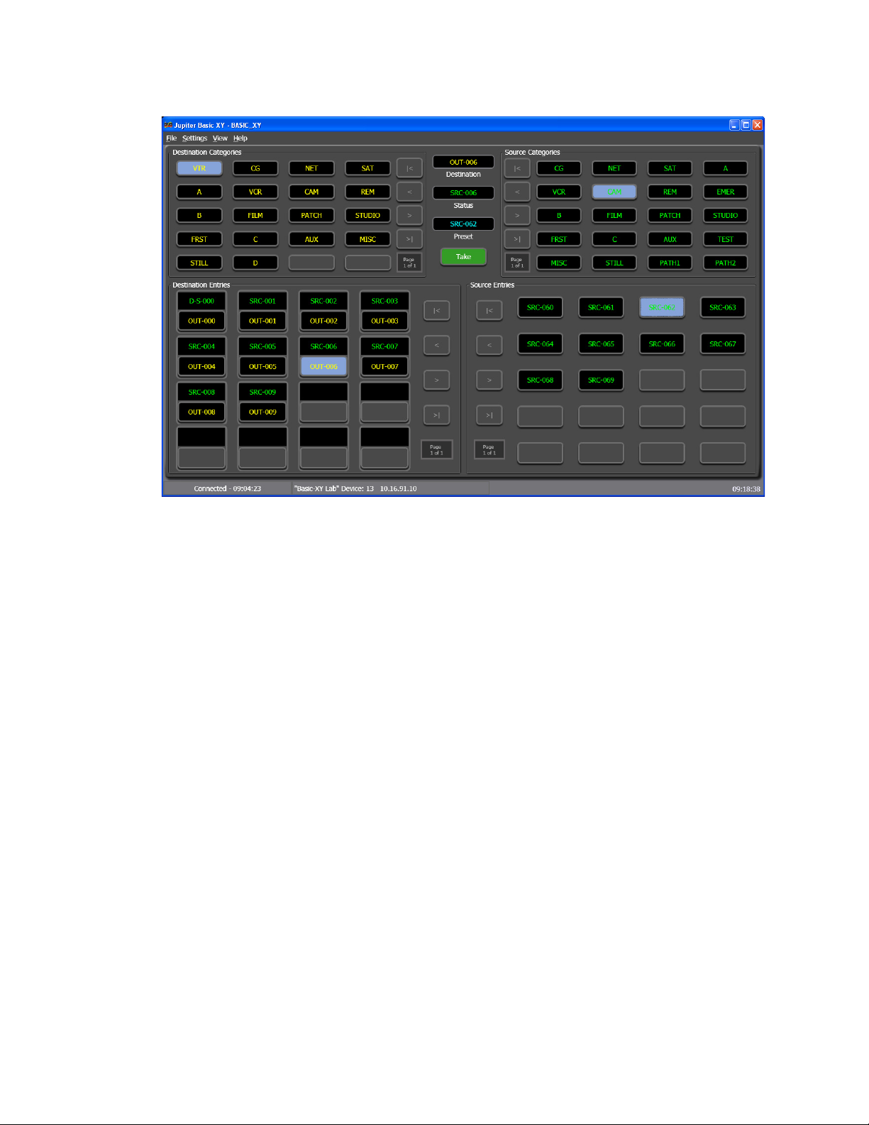
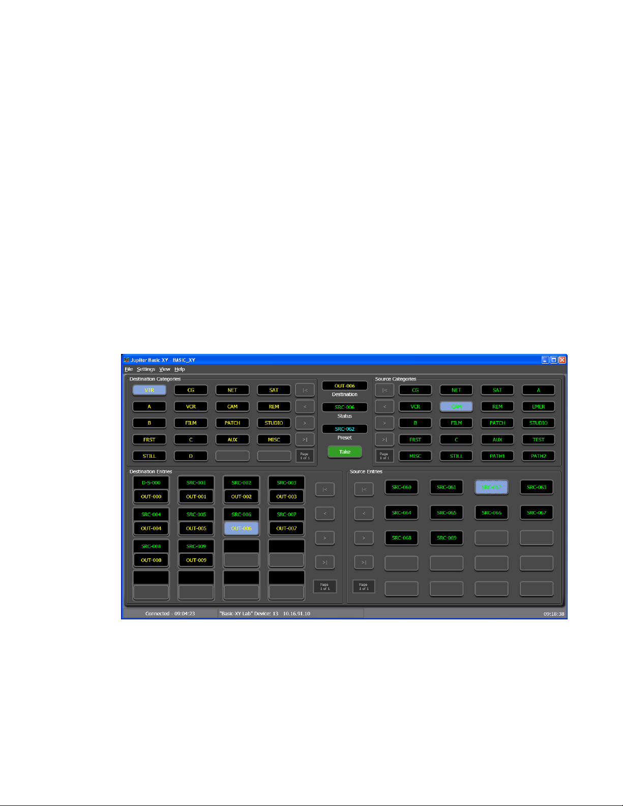
Clicking the Jupiter Basic XY desktop icon (or running the BasicXYPanel.exe file) will open the Basic XY Soft Panel screen see Figure 20. The
Destinations and Sources will be displayed on the buttons once the panel
has been configured.
Figure 20. The Basic XY Application
Section 2
The Menu Bar
The Menu Bar contains different menus for the application. This Menu bar
follows Windows standards, with some additional application specific
functions.
JUPITER AccuSwitch Soft Panels and Visual Status Display Instruction Manual 21
Page 30

Section 2 — Basic XY Soft Panel
File Menu
Router Connection: Opens the Router Connection Settings window. This
window is where the Setting Name, Device ID, and the IP address of the
server to which the Soft Panel will connect.
Note The maximum length of a Settings name in the Router Connection Settings
Router Disconnect: Disconnects Soft Panel from the server.
Router Reconnect: Reconnects to the server using the most recent settings.
System Connections: Provides a list of available connections that have
been saved and can be used to connect to a server.
Exit: Closes the Soft Panel application.
Settings Menu
Change/Set Password: Opens the Password window. See the Setting Pass-
word Protection section for more information.
window is 16 characters.
Skip Empty Category: Groups the categories together when this option is
selected. When it is not selected, the application will display the spaces
between categories that are in the category table.
View Menu
Options: Opens the Options window. See the Options section for more
information.
Help Menu
The Help menu currently has the About Jupiter Basic XY option. An About
screen will appear when this option is selected. The About screen has the
following information: Copyright information, the name of the application,
and the current version number of application. An example of the About
screen is shown below in
Figure 21. The About Screen
Figure 21.
Click the OK button to close the About screen.
22 JUPITER AccuSwitch Soft Panels and Visual Status Display Instruction Manual
Page 31

Display Fields and Buttons
Connected Setting Current Time
The Basic XY Soft Panel Screen’s display fields and buttons definitions are
provided below, in clockwise order.
Source Categories - Displays the matrix router source categories that can be
selected by this Soft Panel.
Source Entries - Displays the specific matrix router sources that can be
selected by this Soft Panel.
Destination Categories - Displays the matrix router destination categories that
can be controlled by this Soft Panel.
Destination Entries - Displays the specific matrix router destinations that can
be controlled by this Soft Panel.
Page Indicator - Displays what page is being displayed for the Destination
Categories, Source Categories, Destination Entries, and Source Entries sec
tions (For example, page 1 of 2.).
Destination - Displays the destination that is presently being controlled by
the panel.
Basic XY Soft Panel Screen Description
-
Status Bar
Status - Displays the source presently switched to the panel's controlled des-
tination (shown for the first router level listed in the Jupiter CP Level Set or
CP Output Level Set--usually video).
Preset - Displays a preview of the names of the new sources after they are
selected.
Take button - Switches the Preset source to the indicated Destination.
The Status bar, which is at the bottom of the interface shows three items of
information: Connected, Settings, and the Current time (
these items is described below.
Figure 22. Basic-XY Panel Status Bar
Figure 22). Each of
Connected: Shows the time that the XY Panel was successfully connected
to the controller. This time is the PC’s Current time.
JUPITER AccuSwitch Soft Panels and Visual Status Display Instruction Manual 23
Page 32

Section 2 — Basic XY Soft Panel
Settings: Shows the Setting name, the Device ID and the IP address that
was used to connect to the Controller network.
Current Time: Shows the PC’s Current time.
24 JUPITER AccuSwitch Soft Panels and Visual Status Display Instruction Manual
Page 33

Basic XY Soft Panel Operating Procedures
Basic XY Soft Panel Operating Procedures
Making a Destination Selection / Status Check
Follow these steps to select a destination prior to making a switch or to
check status:
1. Select a new destination category; VTR is used in the example below
(Figure 23). This selection will populate the Destination Entries fields
with the available destinations in the selected category.
Figure 23. Destination Category Section
2. Choose a destination entry; VTR-1801 is used in the example below
(Figure 24). The name of the destination will be shown in the
Destination window (shown above the “entry” button) and the name of
the source that is currently switched to this destination, will be shown
in the Status window. The Status window is located in the top half of
the interface, in between the Destination Categories and the Source
Categories sections. See Figure 20 on page 21.
Figure 24. Destination Entries Section
JUPITER AccuSwitch Soft Panels and Visual Status Display Instruction Manual 25
Page 34

Section 2 — Basic XY Soft Panel
Note Panels will show eight asterisks (****) as a status, when the panel has no
When a panel cannot be changed to the desired output, the panel may have
been limited to certain outputs by the CP Output set used on the Jupiter
MPK Devices table.
Source and Destination Paging Buttons
The Source and Destination Paging buttons are used to scroll through and to
see the destinations and the source panel’s options. Sometimes, all of these
destination and source options cannot fit on the screen. The “paging”
buttons will be active when there are options that are “off screen”, if not,
they will be grayed out.
description of what the button will do when it is clicked.
way of reporting the mnemonic of the source. This condition could occur
when a source that is selected by panel “B” has the same destination that is
being “statused” by Panel “A,” and this source is not available in the configuration for panel “A.”
Ta bl e 4 on page 26 will provide the names and a
Table 4. The Paging Buttons
The Start button: Clicking this button will show the beginning
options on the “list.”
The Previous button: Clicking this button will show the preceding options.
The Next button: Clicking this button will show the succeeding options.
The End button: Clicking this button will show the last options
on the “list.”
Page Indicator: Displays what page is being displayed for the
Destination Categories, Source Categories, Destination
Entries, and Source Entries sections (For example, page 1 of
2.).
Source Selection (All Levels Take)
Note The Basic XY application does not allow switching levels independently.
Follow these steps to make a Source selection:
1. Check that the desired destination has been selected.
26 JUPITER AccuSwitch Soft Panels and Visual Status Display Instruction Manual
Page 35

Basic XY Soft Panel Operating Procedures
2. Select the desired source category; MISC is used in the example below
(Figure 25). This selection will populate the Source Entries fields with
the available sources for the selected category (Figure 26).
Figure 25. Source Category Section
3. Choose a source entry; ARC-OUT3 is used in the example below
(Figure 26). This selection will then load the source name in the Preset
window (Figure 27).
Figure 26. Source Entries Section
Figure 27. Preset Window
4. Click the Take button. The newly switched source will then be shown in
the Status window (Figure 28).
JUPITER AccuSwitch Soft Panels and Visual Status Display Instruction Manual 27
Page 36

Section 2 — Basic XY Soft Panel
Figure 28. Status Window
Advise Option
When the Advise flag option has been set in the Jupiter Control system and
an attempt is made to switch a Source to a new Destination, the switch will
not occur. The Basic XY panels will instead display the following message
on the control panel:
SRC in use by: <Destination name>
This message will be displayed for approximately three (3) seconds and
will then disappear.
Swap/Undo
You will not be able to switch to a new device until the destination that is
using the source is either:
• Switched to a different source.
• Switched to the “SAFE” input.
Note The Advise option will not work when you are using Sequences or Multiple-
destination switching when the same source is being routed to more than one
destination.
This option will avoid having the Source connected to two Destinations at
the same time.
After each switch, the previous source will automatically return to the
Preset display so that each “
flop.” (The Preset display will be cleared when a new source or destination
is selected.)
Tak e” will make the last two sources to “flip-
28 JUPITER AccuSwitch Soft Panels and Visual Status Display Instruction Manual
Page 37

Multi-Level XY Soft Panel
Multi-Level XY Soft Panel Main Screen Description
Clicking the Jupiter Multi-Level XY desktop icon, or running the MultiLevelXYPanel.exe file, will open the Multi-Level XY Soft Panel application.
The destinations and sources will be displayed on the buttons once the
panel has been configured (
Figure 29. Multi-Level XY Soft Panel
Figure 29).
Section 3
JUPITER AccuSwitch Soft Panels and Visual Status Display Instruction Manual 29
Page 38

Section 3 — Multi-Level XY Soft Panel
The Menu Bar
The Menu Bar contains different menus for the application. This Menu bar
follows Windows OS standards, with some additional application specific
functions.
File Menu
Router Connection: Opens the Router Connection Settings window. This
window is where the Setting Name, Device ID, and the IP address of the
server to which the Soft Panel will connect.
Note The maximum length of a Settings name in the Router Connection Settings
Router Disconnect: Disconnects the Soft Panel application from the server.
Router Reconnect: Reconnects the Soft Panel application to the server
using the most recent settings.
System Connections: Provides a list of available connections that have
been saved and can be used to connect to a server.
window is 16 characters.
Exit: Closes the Soft Panel application.
Settings Menu
Assign Function Key: Opens the Assign Function Key window. See the
Assigning a Function Key section for more information.
Change/Set Password: Opens the Password window. See the Setting Pass-
word Protection section for more information.
Skip Empty Category: Groups the categories together without blank
spaces when this option is selected. When it is not selected, the application
will display the spaces between categories that are in the category table.
Sequences Menu
Local Sequences: Opens the Sequences window. See the Sequence Opera-
tions section for more information.
Jupiter System Sequences: Opens the Jupiter System Sequences window.
See the
View Menu
Jupiter System Sequences section for more information.
Options: Opens the Options window. See the Options section for more
information.
30 JUPITER AccuSwitch Soft Panels and Visual Status Display Instruction Manual
Page 39

Help Menu
Multi-Level XY Soft Panel Main Screen Description
The Help menu currently has the About Jupiter Multi-Level XY option. An
About screen will appear when this option is selected. The About screen
has the following information: Copyright information, the name of the
application, and the current version number of application. An example of
the about screen is shown below (
Figure 30. The Multi-Level XY About Screen
Click the OK button to close the About screen.
Figure 30).
Multi-Level XY Soft Panel Descriptions
Display Fields
The definitions for the Multi-Level XY soft panel screen’s display fields are
provided below.
Source Categories - Displays the matrix router source categories that can be
selected by this Soft Panel.
Source Entries - Displays the specific matrix router sources that can be
selected by this Soft Panel.
Destination Categories - Displays the matrix router destination categories that
can be controlled by this Soft Panel.
Destination Entries - Displays the specific matrix router destinations that can
be controlled by this Soft Panel.
Page Indicator - Displays what page is being displayed for the Destination
Categories, Source Categories, Destination Entries, and Source Entries sec
tions (For example, page 1 of 2.).
Preset - Displays a preview of the names of the new sources after they have
been selected. After the
shown in the Preset row, which allows you to “flip-flop” the sources, or to
switch between the current and preset sources by repeatedly pressing the
Take button.
Take button is pressed, the previous source is then
-
Status - Displays the source presently switched to the panel's controlled des-
tination (shown for the levels listed in the “Level” row).
JUPITER AccuSwitch Soft Panels and Visual Status Display Instruction Manual 31
Page 40

Section 3 — Multi-Level XY Soft Panel
Level - Displays the level names that have been established by the Jupiter CP
Level Set. The first level is usually video; the remainder are usually audio.
Destination - Displays the destination that is presently being controlled by
the panel.
Source and Destination Paging Buttons
The Paging buttons are used to scroll through and see the destination and
source panel’s options. Sometimes, all of these destination and source
options cannot fit on the screen. The
“off screen” options, if not, they will be grayed out.
will provide the names and a description of what the button will do when
it is clicked.
Table 5. The Paging Buttons
Paging buttons will be active if there are
Ta bl e 5 shown below,
The Start button: Clicking this button will
show the beginning options on the “list.”
The Previous button: Clicking this button
will show the preceding options.
Control Buttons
Take - Switches the Preset source to the indicated Destination.
Clear Preset - Clears the Preset display.
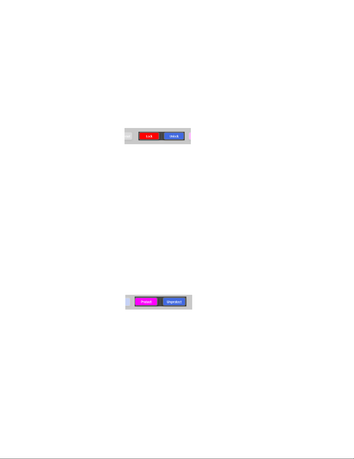
Lock - Prevents the selected destination from being switched by any panel
in the system, including the initiating panel. Each level can be locked or
protected individually. A Locked destination is indicated by red lettering
when using default color display options.
Unlock - Unlocks the destination if this panel locked the destination.
The Next button: Clicking this button will
show the succeeding options.
The End button: Clicking this button will
show the last options on the “list.”
Page Indicator: Displays what page is
being displayed for the Destination Categories, Source Categories, Destination
Entries, and Source Entries sections (For
example, page 1 of 2.).
Protect - Prevents the selected destination from being switched by any other
panel in the system. A protected destination is indicated with magenta let
tering, when using default color display options.
32 JUPITER AccuSwitch Soft Panels and Visual Status Display Instruction Manual
-
Page 41

Status Bar
Connected Setting Current Time
Multi-Level XY Soft Panel Main Screen Description
Unprotect - Removes the Protected status if this panel locked the destination.
The destination can then be switched by any panel in the system.
Save Status - Saves the selected destination’s current status to be recalled
later as the preset source of another switch.
Recall to Preset - Recalls a saved switch configuration. Switch configuration
is one destination with a source per level. Each level can have a different
source, but only one destination. Multiple destinations need to use Local
sequences.
CAUTION Selecting the Recall to Preset button, and then clicking the Take button, will
execute the recalled source(s), level combination to the single defined destination from the saved file.
Sticky Levels - When clicked, after a Take is performed the selected levels will
remain selected until deselected or the destination is changed.
The Status bar, which is at the bottom of the interface shows three items of
information: Connected, Settings, and the Current time (
these items is described below.
Figure 31). Each of
Figure 31. Multi-XY Panel Status Bar
Connected: Shows the time that the XY Panel was successfully connected
to the controller. This time is the PC’s Current time.
Settings: Shows the Setting name, the Device ID and the IP address that
was used to connect to the Controller network.
Current Time: Shows the PC’s Current time.
JUPITER AccuSwitch Soft Panels and Visual Status Display Instruction Manual 33
Page 42
Section 3 — Multi-Level XY Soft Panel
Multi-Level XY Soft Panel Operating Procedures
Destination Selection / Status Check
Follow these steps to select a destination prior to making a switch or to
check status:
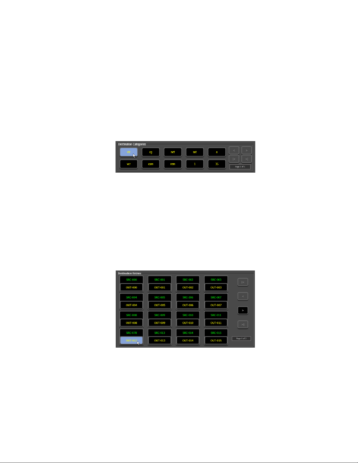
1. Select a new destination category; vtr is used in the example below
(Figure 32).
Figure 32. Destination Category Section
This step will populate the Destination Entries fields with the available
destinations in the selected category.
To scroll to additional categories, use the Paging buttons in the Destina-
tion Category field. Clicking the Last button will scroll to the last available category. The Paging buttons will only be available if there are
options that are not shown.
2. Choose a destination entry; OUT-012 is used in the example below
(Figure 33).
Figure 33. Destination Entry Section
To scroll to additional entries, use the Paging buttons in the Destination
Entries field.
The name of the selected destination will be shown in the Destination
window (at the bottom of the screen). The name of the source(s) cur
rently switched to this destination will be shown in the Status row.
34 JUPITER AccuSwitch Soft Panels and Visual Status Display Instruction Manual
-
Page 43
Note Panels will show eight asterisks (****) as a status, when the panel has no
way of reporting the mnemonic of the source. This condition could occur
when a source that is selected by panel “B” has the same destination that is
being statused by Panel “A,” and this source is not available in the configuration for panel “A.”
Panels that cannot be changed to the desired destination may have been
restricted to certain destinations by the CP Output set that is used on the
Jupiter MPK Devices table.
Source Selection (All Levels Take)
To select a source:
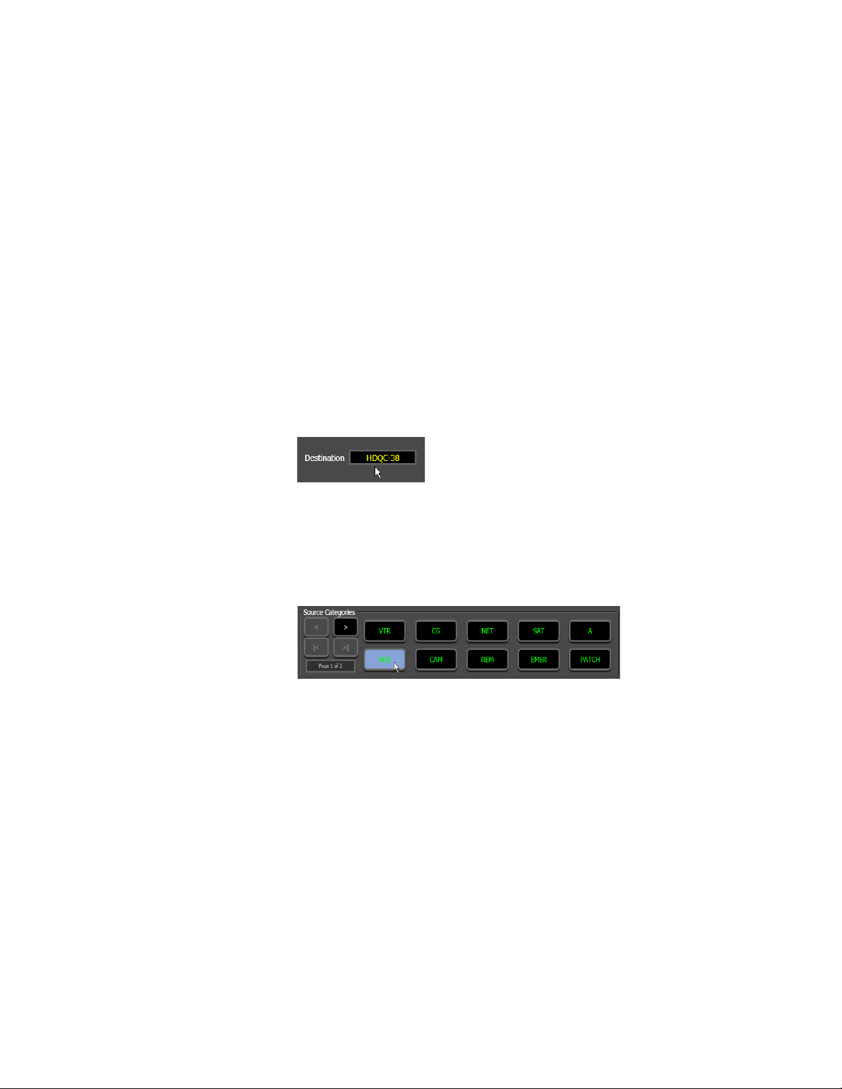
1. Check that the desired destination is shown in the Destination window,
which is located in the lower left-hand corner of the interface.
Figure 34. Destination Window
Multi-Level XY Soft Panel Operating Procedures
2. Select the desired source category; VCR is used in the example below
(Figure 35). This selection will populate the Source Entries fields with
the available sources in the selected category.
Figure 35. Source Category Section
3. Choose a source entry; SRC-072 is used in the example below (Figure 36
on page 36).
JUPITER AccuSwitch Soft Panels and Visual Status Display Instruction Manual 35
Page 44

Section 3 — Multi-Level XY Soft Panel
Figure 36. Source Entry Section
Selecting the source entry will load the source name in the Preset row.
Take button will then be enabled.
The
4. Click the Take button.
The newly switched source will now be shown in the Status row
Figure 37).
(
Advise Option
Figure 37. Status Row
When the Advise flag option has been set in the Jupiter Control system and
an attempt is made to switch a Source to a new Destination, the switch will
not occur. The Multi-Level XY panels will instead display the following
message on the control panel:
SRC in use by: <Destination name>
This message will be displayed for approximately three (3) seconds and
will then disappear.
You will not be able to switch to a new device will not be executed until the
destination that is using the source is either:
• Switched to a different source.
• Switched to the “SAFE” input.
Note The Advise option will not work when you are using Sequences or Multiple-
destination switching when the same source is being routed to more than one
destination.
36 JUPITER AccuSwitch Soft Panels and Visual Status Display Instruction Manual
Page 45

This option will avoid having the Source connected to two Destinations at
the same time.
Swap/Undo
After each switch, the previous source automatically returns to the Preset
row so that each “Take” causes the last two sources to flip-flop. (The Preset
row is cleared when a new destination is selected.)
Level Breakaways (Split Switching)
This function allows different sources to be selected for different levels. For
example, you have the ability to switch the video without having to switch
the audio as well.
Checking Status of Selected Level
Multi-Level XY Soft Panel Operating Procedures
Select the desired destination category and entry. The status of each router
level will then be shown in the Status row, which is located at teh bottom of
the application.
Performing a Breakaway Switch
Follow these steps to perform a breakaway switch:
1. Select the desired destination category and destination entry.
2. Toggle on/off the desired levels by clicking the level in the Status row.
This will outline the fields for the selected levels (Figure 38).
Figure 38. Status Row Selected
3. Select the desired source category and source entry.
This will load the Preset fields for the selected levels.
4. Press the Tak e button to execute the breakaway switch.
When the switch is complete the panel will revert to all-level switching if
Sticky Levels button is selected. If the Sticky Levels button is selected, then
the
the selected levels remain selected; otherwise, all level will be deselected.
JUPITER AccuSwitch Soft Panels and Visual Status Display Instruction Manual 37
Page 46
Section 3 — Multi-Level XY Soft Panel
Locking and Unlocking a Destination
Locking a destination prevents that destination from being switched by
any panel in the system, including the initiating panel.
Follow these steps to lock a destination:
1. Click the Lock button. If no levels are selected, all valid levels for the
destination will be locked. If levels are selected, only the selected levels
will be locked.
Figure 39. Lock and Unlock Buttons
2. The status row will then change to the color that is assigned in the
Options dialog (Menu bar: View> Options...).
To unlock the destination click the Unlock button. This will affect the same
levels as the Lock operation.
Protecting or Un-protecting a Destination
Protecting a destination prevents that destination from being switched by
any other panel in the system.
Follow these steps to protect a destination:
1. Click the Protect button. If no levels are selected, all valid levels for the
destination will be protected. If levels are selected, only the selected
levels will be protected.
Figure 40. Protect and Unprotect Buttons
2. The status row will then change to the color that is assigned in the
Options dialog (View> Options...).
To unprotect the destination, click the Unprotect button. This will affect the
same levels as the Protect operation.
Tool Tip Help
Hovering over a locked/protected destination shows the name of the panel
that locked/protected that destination (
38 JUPITER AccuSwitch Soft Panels and Visual Status Display Instruction Manual
Figure 41 on page 39).
Page 47

Figure 41. Tool Tip Help
Multi-Level XY Soft Panel Operating Procedures
JUPITER AccuSwitch Soft Panels and Visual Status Display Instruction Manual 39
Page 48

Section 3 — Multi-Level XY Soft Panel
Sequence Operations
The Multi-Level XY Soft panel can define the sequences (salvos) to be used
by that panel, import sequences from other Soft Panels, export sequences
for use by other Soft Panels, and execute local or Jupiter system sequences
that are assigned to the Soft Panel as a “Sequence Set” in the Jupiter MPK
Ta bl e.
Local Sequences Screen Descriptions
The Sequence screen can be accessed from the Menu bar by selecting:
Sequences> Local Sequences. Each area of the Sequence screen is identified
in
Figure 42 on page 41.
The definitions for each area are provided below the screen. These definitions will be used throughout the rest of the section.
40 JUPITER AccuSwitch Soft Panels and Visual Status Display Instruction Manual
Page 49

Figure 42. Local Sequences Screen
Sequence
Name section
Existing Sequence
section
Sequence Command section
Sequence List section
Sequence Operations
Sequence Name
This section contains the buttons for saving, creating a new sequence, creating a new entry, and deleting an entry.
Save - Saves the sequence defined on the screen.
New Sequence - Creates a new sequence to be edited.
New Entry - Adds a new row/entry to the sequence on the screen.
Delete Entry - Removes an entry from the sequence on the screen.
JUPITER AccuSwitch Soft Panels and Visual Status Display Instruction Manual 41
Page 50

Section 3 — Multi-Level XY Soft Panel
Existing Sequences
This section contains the buttons for working with current sequences.
Existing Sequences drop-down list - Displays any previously created sequence.
View Sequence - Applies the sequence selected from the pull down list to the
screen to be viewed or edited.
Remove Sequence - Deletes the selected sequence.
Import Sequence - Allows an exported sequence from another panel to be
imported into this panel.
Export Sequence - Allows a panel defined sequence to be exported so another
panel can use it.
Sequence List
This section is where the list of sequences will be displayed. Each group of
sequences is displayed as numbered entries.
Destination - Contains destinations that can be used for that entry of the
sequence.
All Levels - Allows all levels to use the same source, when selected. Each
level can use a different source, when the button is not selected.
Level Pull Downs - Selects the source to be switched to the destination on that
level.
Sequence Commands
This section contains the buttons for executing the sequences and closing
the Soft Panel application.
Sequence field- Displays the name of the current sequence that is currently on
the screen.
Execute Sequence - Executes the sequence currently defined on the screen.
Close - Exits the Local Sequences window.
Creating a Local Sequence
A local sequence must be created, or defined, before it can be viewed, executed, or be exported.
Follow these steps to create a local sequence:
1. Click the New Sequence button. The Save Changes dialog will then appear,
informing you that, “Any changes will be lost, do you want to
continue”? (Figure 43 on page 43)
42 JUPITER AccuSwitch Soft Panels and Visual Status Display Instruction Manual
Page 51

Sequence Operations
Both Levels
can be
selected
2. Click the Yes button.
Note Entries to Local Sequences can also be made by selecting an entry in the
Sequence List and then right clicking. The options are “Insert Entry Above”
the selected item or to “Insert Entry Below” the selected item.
Figure 43. Save Changes Dialog
3. Enter a name to identify the sequence in the Sequence Name field.
4. Select the destination from the Destination drop-down list. In the
example below, (Figure 44) the destination, ACR9-53 has been selected.
Figure 44. Destination Drop-Down List
5. Select the All Levels button if you would like all levels to use the same
source. In the example below, (Figure 45) “All Levels” was turned off.
The second level can now be selected.
Note All Levels are selected by default. Selecting the All Levels button makes each
individual level accessible for a breakaway switch in the sequence.
Figure 45. The All Levels Button -Turned Off
6. Select a source for each level.
Note The “white arrow” on the source drop-down list, shows that a source can be
selected. If a source cannot be selected the “arrow” will be grayed out. See
Figure 46 and Figure 47 on page 44.
Figure 46. Source Selection Options - Can be Selected
JUPITER AccuSwitch Soft Panels and Visual Status Display Instruction Manual 43
Page 52

Section 3 — Multi-Level XY Soft Panel
Both Levels
cannot be
selected
Figure 47. Source Selection Options - Cannot be Selected
7. Click the Save button to retain the selected information for future use.
8. Click the Execute Sequence button. An Execute Sequence dialog will then
appear notifying you that, “The sequence has been sent.” Click the OK
button.
9. Click the Close button, on the Sequence dialog, if you do not want to
execute any more sequences.
Selecting an Existing Sequence
Once a Sequence (or Salvo) has been created and saved, it can be used
again, as needed. The Existing Sequence drop-down list, in the Existing
Sequence section, will show all saved sequences.
Follow these steps to select an existing sequence (or Salvo):
1. Select the sequence from the Existing Sequences drop-down list. In the
example below, (Figure 48) the “Beta” sequence has been selected.
Figure 48. Existing Sequences Drop-Down List
2. Click the View Sequence button. (Figure 49)
Figure 49. Existing Sequences Drop-Down List
The “Beta” sequence’s settings will then appear in the Sequence List.
Removing an Existing Sequence
If you feel that you no longer need to keep a sequence, it can be removed
from the Existing Sequence drop-down list.
44 JUPITER AccuSwitch Soft Panels and Visual Status Display Instruction Manual
Page 53

Sequence Operations
Follow these steps to remove an existing sequence:
1. Select the sequence from the Existing Sequences drop-down list, as
shown in Figure 50.
Figure 50. Existing Sequences Drop-Down List
2. Click the Remove Sequence button, as shown in Figure 51.
Figure 51. Remove Sequences Button
The Remove Sequence dialog will then appear (Figure 52). This dialog
will ask if you want to remove the selected sequence. For this example,
the selected sequence is “Beta”.
Figure 52. Remove Sequence Dialog
3. Click the Yes button.
The “Beta” sequence’s settings will then be removed from the Sequence
List and the Existing Sequencing drop-down list.
Exporting an Existing Sequence
Existing sequences can be exported to a different location, where they can
be used by other Soft Panels.
Follow these steps to export an existing sequence:
1. Select the sequence from the Existing Sequences drop-down list, as
shown in Figure 53.
Figure 53. Existing Sequences Drop-Down List
JUPITER AccuSwitch Soft Panels and Visual Status Display Instruction Manual 45
Page 54

Section 3 — Multi-Level XY Soft Panel
2. Click the Export Sequences button, as shown in Figure 54.
Figure 54. Existing Sequences Drop-Down List
The Export Sequence window will then appear as shown in Figure 55.
Figure 55. Export Sequence List
3. Select the sequence that you want to export and then click the Export
button. For example, in Figure 56 the “Beta” sequence has been
selected. The Save Sequences File window will then appear.
Figure 56. The Save Sequences File Window
4. Navigate to the location where you want to save the sequence.
46 JUPITER AccuSwitch Soft Panels and Visual Status Display Instruction Manual
Page 55

Sequence Operations
5. Enter the name of the sequence file in the File Name field. Ensure that
the Sequence File (*.xml) option is selected in the Save as type field.
6. Click the Save button. The Export Sequence dialog will then appear
(Figure 57 on page 47) informing you that the sequence file was saved.
Figure 57. Existing Sequences Dialog
7. Click the OK button to close the dialog. The Export Sequences dialog will
still be open. Click the
The sequence has been exported and can now be used by other Soft
panels.
Close button to close the dialog.
Importing an Existing Sequence
Existing sequences can be imported from a different location, where they
can then be used by the Soft Panels application. Imported sequences can be
edited to better meet your needs.
Follow these steps to import an existing sequence:
1. Click the Import Sequences button, as shown in Figure 58.
Figure 58. Import Sequences Button
The Open window will then appear as shown in Figure 59.
JUPITER AccuSwitch Soft Panels and Visual Status Display Instruction Manual 47
Page 56

Section 3 — Multi-Level XY Soft Panel
Figure 59. The Open Window
2. Navigate to the location of the sequence that you want to import.
3. Select the sequence file that you want to import.
4. Click the Open button. The Import Sequence dialog will then appear
(Figure 60), informing you the number of sequences that were
imported.
Figure 60. The Import Sequence Dialog
5. Click the OK button to close the dialog.
The sequence has been imported and can now be used by the Soft panel
application.
Jupiter System Sequences
The Multi-Level XY Soft Panel allows you to see the Jupiter-system defined sequences that can be used with this panel.
Follow these steps to use the Jupiter System Sequences:
1. Select Jupiter System Sequences from the Menu bar (Sequences>
Jupiter System Sequences). The Jupiter System Sequences dialog will
then appear (Figure 61).
2. Select the desired sequence from the list.
48 JUPITER AccuSwitch Soft Panels and Visual Status Display Instruction Manual
Page 57
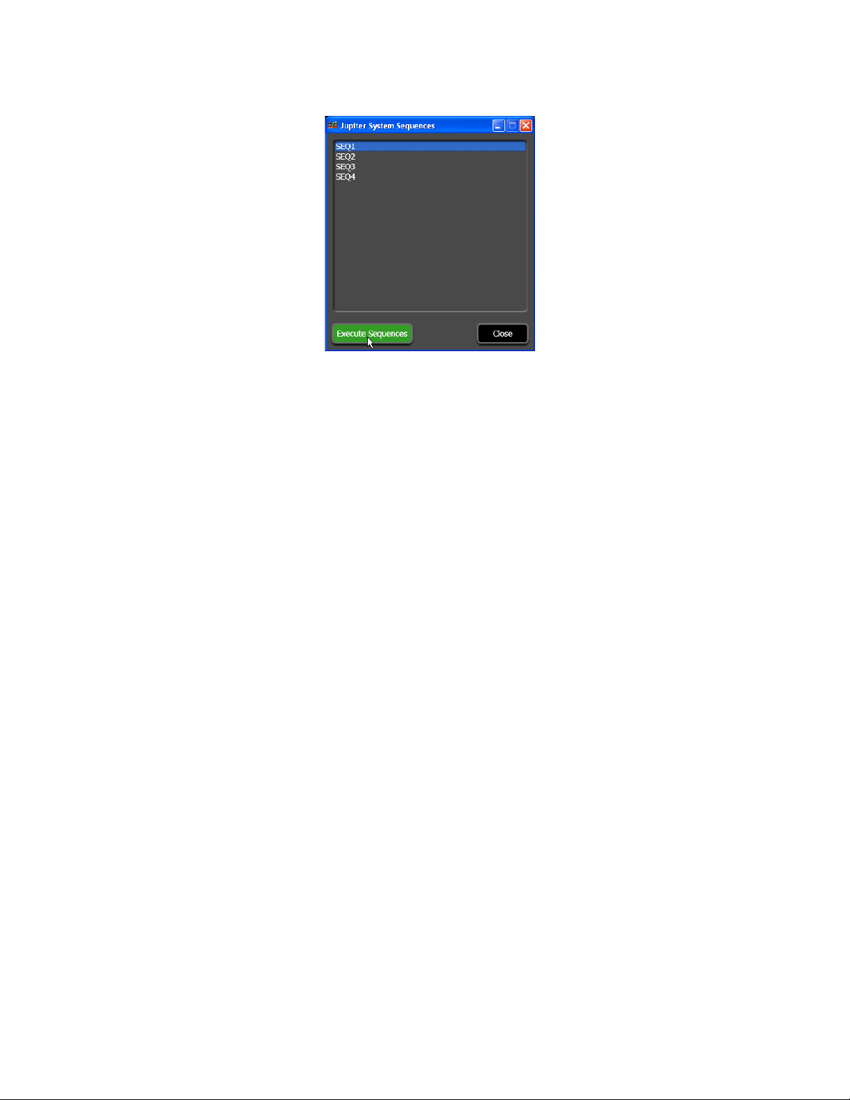
Sequence Operations
Figure 61. Jupiter Defined Sequences List
3. Click the Execute Sequence button. The Jupiter-defined sequence will
then be implemented.
JUPITER AccuSwitch Soft Panels and Visual Status Display Instruction Manual 49
Page 58

Section 3 — Multi-Level XY Soft Panel
50 JUPITER AccuSwitch Soft Panels and Visual Status Display Instruction Manual
Page 59

VSD Introduction
Overview
The Visual Status Display (VSD) application shows the current status of the
configured connections for a Jupiter Accuswitch controlled system. The
VSD application runs on the English version of the Windows XP operating
systems. The PC running VSD needs to be connected to the Jupiter net
work. VSD information is updated automatically. For example, when a
Destination’s routing information changes, if that Destination is currently
displayed, its status will be updated within seconds.
VSD is an option that is registered by entering a license key, obtained from
Grass Valley Customer Service. The license key is valid for only a specific
PC, and only one VSD instance can run on that PC at a time. An unregis
tered VSD operates in trial mode, which limits the maximum number of
elements supported per View to five.
Section 4
-
-
Views
Large routing systems can have many Destinations and complex paths,
making it impossible to see the status of the entire system on a single
screen. VSD permits grouping subsets of the system into Views. Different
Views can be created to quickly display the current status of various por
tions of the system. The types of Views available include:
• Destination view
•Source view
• Control Boards view
•Tie Lines view
The Jupiter VSD also allows you to create unlimited Custom views to better
meet your business needs. Columns of information, within the custom
view, can be hidden and then reveled at a later time.
All columns can be compressed to show only the content or to see all the
columns; as well as zoom in or zoom out to your desired view.
JUPITER AccuSwitch Soft Panels and Visual Status Display Instruction Manual 51
-
Page 60

Section 4 — VSD Introduction
The types of information or “fields” that can be displayed are:
• Switcher Output status (any level)
• Switcher Input status (any level)
• Machine control display
• System time and date
• System control board status, either Active or Inactive
• System control board time source
• System control board messages (not supported in AccuSwitch)
• Pathfinding (Tie line) status
Current VSD Limitations
Note The following limitations exist in the standard Views only. Custom views can
be created to better meet your needs.
VSD Interface
• Elements in a View are automatically sorted by a source or destination
index when the View is closed and re-opened. Any previous order that
was entered will be lost when the View is closed and re-opened.
• Column elements cannot be manually sorted in ascending or
descending order.
• On systems where more than one VSD application is connected, Views
that are deleted, modified, or newly created will not be shared by other
VSD applications that are running.
• Closing and restarting the VSD application will synchronize shared
information, Views will then be dynamically shared with other connected VSD applications.
This section describes the features of the main VSD interface and will
provide the name of the different areas of the interface. These names will
be used throughout the rest of the manual.
52 JUPITER AccuSwitch Soft Panels and Visual Status Display Instruction Manual
Page 61
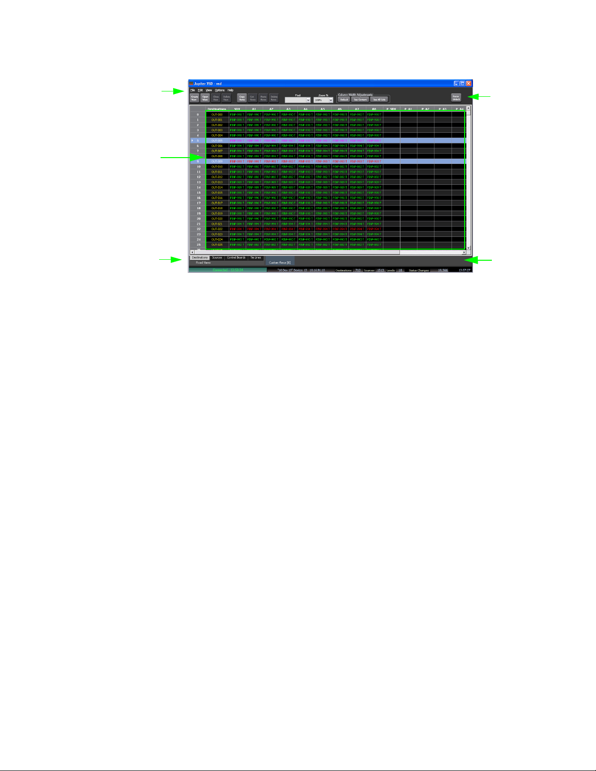
Figure 62. The VSD Interface
View System
Status Area
View Selection
Area
Menu Bar
The Tool Bar
Connection
Information
Area
VSD Interface
The Menu Bar
File
Edit
The Menu Bar contains different menus for the application. This Menu bar
follows Windows OS standards, with some additional application specific
functions.
Router Connection: Opens the Router Connection Settings window. This
window is where the Setting Name, Device ID, and the IP address of the
server that the VSD will connect to.
Router Disconnect: Disconnects VSD from the server.
Router Reconnect: Reconnects to the server using the most recent settings.
System Connections: Provides a list of available connections that have
been saved and can be used to connect to a server.
Exit: Closes the VSD application.
Cut, Copy, Paste: Standard clipboard style editing controls.
Delete: Removes the selected row from the custom view.
JUPITER AccuSwitch Soft Panels and Visual Status Display Instruction Manual 53
Page 62

Section 4 — VSD Introduction
View
Create Custom View: Opens a new Custom view window allowing entry
of the IP address of the server to which the VSD will connect. A row must
be selected for this button to be active.
Open Custom View: Opens the Open Custom View window. Any custom
view, that is closed, will be listed in the window.
Close Current View: Closes the view that is currently being shown.
Delete Current View: Removes the existing View.
Tools
Change/ Set Password: Opens the Password dialog.
Tie Line Clearing Editor: Opens the Tie Line Clearing Editor.
Options: Opens the Options window allowing changes to VSD settings.
Help
The Tool Bar
View Buttons
About Jupiter VSD: Opens the About Jupiter Visual Status Display screen.
This screen displays information about the Jupiter VSD including the
Version number. An example of the About screen is shown below in
Figure 63.
Figure 63. The Jupiter VSD About Screen
The Tool bar is a group of tools that you will use most often.
Create View: Opens a new Custom view window allowing entry of the IP
address of the server to which the VSD will connect. A row must be selected
for this button to be active.
Open View: Opens the Open Custom View window. Any custom view,
that is closed, will be listed in the window.
54 JUPITER AccuSwitch Soft Panels and Visual Status Display Instruction Manual
Page 63

Close View: Closes the view that is currently being shown.
Clipboard Buttons
Copy Rows: Copies the contents of the selected rows.
Cut Rows: Cuts the contents of the selected rows.
Paste: Pastes the contents of the selected rows.
Delete Rows: Deletes the contents of the selected rows.
Search Field
You can search for specific, Destinations, Sources, Groups and so forth by
entering the item to search for in the Search field.
Zoom% Field
You can allow change the display size, by zooming in or out, so the VSD can
be read from varying distances.
VSD Interface
Column Width Adjustments
Default: Removes any adjustments to the column widths.
See Content: Expands the columns so all the data can be seen.
See All Cols: Contracts the columns so all the columns can be seen.
Force Unlock Button
The VSD can force unlock any destination regardless of what panel locked
or protected it. In order for Force Unlock to be enabled, the VSD must be
defined with a password of 90 – 99 in MPK Devices table of the Jupiter
Editor. The
enough and a locked/protected cell is selected.
Note If AccuSwitch or Jupiter locks or protects a Destination on a 3rd party router
Force Unlock button will only be enabled if the password is high
that is shared with another control system, there is the possibility that after a
pmemClear command occurs on the AccuSwitch/Jupiter Control system that
the destination will report as being locked or protected by the 3rd party’s
control system. This Destination will have to be Force unlocked by an AccuSwitch/Jupiter Control system with Force Unlock privileges to regain control
of the Destination.
JUPITER AccuSwitch Soft Panels and Visual Status Display Instruction Manual 55
Page 64

Section 4 — VSD Introduction
The View System Status Area
The View System Status area contains the information for the different
fixed views. The information that is displayed will change depending on
what View is selected. The different views are listed below in the View
Selection Area section.
The View Selection Area
The View Selection area contains the different fixed views and will list the
Custom view that is being used. The number of custom views available is
also displayed. The fixed view’s definitions are provided below.
Destinations view: Displays the destination’s or “output” categories, the lock
and protected status and the Levels for each destination. For more informa
tion, see the Destinations View section.
Sources view: Displays the input categories and level statuses that have
been configured for the selected router. The Lock and Protected status is
shown on the page by color. For more information, see the
tion.
-
Sources View sec-
Control Boards view: Displays the name, type, status, uptime, IP address and
the MAC address for all configured control boards.
Tie Line view: Displays the group number, the Tie line number, the source,
the status, the number of destinations, the source router, and the destina
tion router.
Custom views: Displays the name of the custom view that is being used and
the number of custom views that are available.
The Connection Information Area
The Connection Information area contains the information about the router
to which the VSD is connected and the status of the VSD. The connection’s
definitions are provided below.
Connection Status: Displays the status of the connection between the VSD
and the router.
Connection Settings: Displays the Setting’s name, IP address and the Device
ID the VSD is using to connect to the router.
Destinations: Displays the number of destination between the VSD and the
router.
-
Sources: Displays the number of sources between the VSD and the router.
Levels: Displays the number of levels between the VSD and the router.
56 JUPITER AccuSwitch Soft Panels and Visual Status Display Instruction Manual
Page 65

VSD Interface
Status Changes: Displays the number of changes that have occurred and displays the current time for the PC on which the VSD is installed.
JUPITER AccuSwitch Soft Panels and Visual Status Display Instruction Manual 57
Page 66

Section 4 — VSD Introduction
Interface Views
This section describes the features of the different VSD interface Views.
There are four fixed views: Destinations, Sources, Control Boards, and Tie
Lines. Each Fixed view is described below.
Destinations View
The Destination view displays the output categories and level statuses that
have been configured for the selected router. The actual column headings
and rows will depend on your router-configuration settings. The Lock and
Protected status is shown on the page by color. Holding your mouse over a
locked/protected destination will show the name of the panel that locked/
protected that destination.
Figure 64. The Destinations View
Sources View
The Sources view displays the input categories for specific Destinations. A
single Source can be routed to multiple Destinations. All the Destinations
that a Source is routed to, and the status of that Source, are automatically
displayed in this view. The actual column headings and rows will depend
on your router-configuration settings. The sources that are Locked and Pro
tected are identified on the page by color. See the Use of Color section for
more information.
-
58 JUPITER AccuSwitch Soft Panels and Visual Status Display Instruction Manual
Page 67

Figure 65. The Sources View
Interface Views
Control Boards View
The Control Boards view will obtain and the display the data from communicating with an AccuSwitch board. The definition for each column
heading is provided below.
Figure 66. The Control Boards View
Column Headings
Control board: The control board is the name that is given a CM by the user
JUPITER AccuSwitch Soft Panels and Visual Status Display Instruction Manual 59
Page 68

Section 4 — VSD Introduction
Board Type: The board type is the kind of controller that is being monitored.
Status: The status is the current state of the board. For example, the status
can be Active or Back-up.
Uptime: The uptime is the amount of time that has passed since the board
was last restarted.
IP Address: The IP Address is the Internet Protocol address or the Ethernet
address for the Control board. The IP address is displayed in dot notation.
For example, 10.16.4.5.
MAC Address: The Media Access Control address for the Control board.
Tie Lines View
The Tie Lines view will show the tie lines or the connections between
routers that are assigned to a specific page and their status. The definition
for each column heading is provided below.
Figure 67. The Tie Line View
Column Heading
Tie Lines: The Tie Lines column displays a group of connections.
Tie Lines #: The Tie Lines # column displays the individual connections
that are part of the group of connections.
Source: The source column displays the input source’s mnemonic for the
connection.
60 JUPITER AccuSwitch Soft Panels and Visual Status Display Instruction Manual
Page 69

Status: The Status column displays the condition of the connection. Possible status categories are: Normal, Protected, Locked, and Prioritized.
# Dest: The # Dest column displays how many destinations that are
assigned to the connection.
Destination: The Destination column displays the assigned destination
source’s mnemonics for the connection.
From Router (Level): The From Router (Level) column displays the name
of the router and the specific card that the connection will come from.
To Router (Level): The To Router (Level) column displays the name of the
router and the specific card to which the connection will be sent.
The Router Connection Settings Window
The Router Connection Settings window, which is shown in Figure 68, is
accessed from the File menu. The features of this window are explained
below.
Interface Views
Figure 68. VSD Router Connection Settings Window
Clear Selected Tie Lines button: The Tie Line view will be updated and the
selected Tie lines will be cleared.
Section Headings
Setting Name: The Settings drop-down list will display the available file
names. This list is where you can add a new Setting name. Clicking the
button creates a new set of settings. Clicking the
the displayed settings. Clicking the
Save button saves the settings.
Delete button will remove
New
Note The maximum length of a Settings name is 16 characters.
System Connection (file Menu) button: Enables the System Connections
option to the File menu. Selecting the System Connection (file menu) option
JUPITER AccuSwitch Soft Panels and Visual Status Display Instruction Manual 61
Page 70

Section 4 — VSD Introduction
will add this connection to the System Connections option in the file menu.
The System Connections option is only enabled when there are connections
that are associated with the System Connection (file menu) option set.
Protocol: The only protocol option is ES LAN.
ES LAN Settings: The ES LAN setting contains the information needed to
connect to the Jupiter network. This information is the Main and backup IP
Addresses and the Device ID.
PC IP Address: The PC IP Address field displays the IP address for the PCs
NIC card. Multiple NIC cards can be selected from the drop-down list.
Connect button: The Connect button will apply the current settings and will
then connect to the provided network, when the
Cancel button: The Cancel button will close the Router connections without
connecting to the network.
The Open Custom View Window
Connect button is clicked.
The Open Custom View window, which is shown in Figure 69, is accessed
from the View menu. It is used to open the custom views that have been
created and saved.
Figure 69. Open Custom View Window
The Options Window
The Options window, shown in Figure 70, is accessed through the Options
menu. The features of this window are explained below.
62 JUPITER AccuSwitch Soft Panels and Visual Status Display Instruction Manual
Page 71

Figure 70. Options Window
Section Headings
Connection at Startup: Provides options for how the VSD application will
connect when it is started.
Interface Views
• Do NOT attempt to connect at startup: The VSD application will
not connect to the control panel when it is started.
• Attempt the last successful connection: The VSD application will
connect to the last control panel it was connected to when it is
started.
Miscellaneous: Provides various VSD options.
• Apply Zoom% to all views of the same type: Applies the zoom percentage to all views.
• Require Password to Open Options: Turning on this feature will
require a password to open the Options dialog.
Grid Colors: Provides a way to change how the following will be displayed: Source Text color, Destination Text color, Selection background,
Locked Text color, and Protected Text color. Clicking the
of the above mentioned options will open the Color dialog.
Edit button for any
Buttons
Restore All Defaults button: Provides a way to return to the original
display options.
OK button: Provides a way to save and apply changes, then closes the
Options window.
Cancel button: Provides a way to close the Options window without
saving changes.
JUPITER AccuSwitch Soft Panels and Visual Status Display Instruction Manual 63
Page 72

Section 4 — VSD Introduction
Use of Color
The VSD uses color to indicate the following functionality:
Table 6. Colors and Functionality
Button Color Function
Green Sources
Yellow Destinations
Red Lock status
Magenta Protect status
Blue Pathfinding (tie lines)
Gray Duplicate destinations
The VSD will also show the CM status using the following colors:
Table 7. Color and Function for Menus
Menu Color Function
Green Primary boards
Cyan Redundant boards
64 JUPITER AccuSwitch Soft Panels and Visual Status Display Instruction Manual
Page 73

Interface Views
Requiring a Password to Change Settings on the Options Dialog
You can limit the ability to change the settings on the Options dialog by
requiring a password to make changes.
Note This required password is the one that is set for the entire control panel
(Tools> Change/Set Password..). Follow these steps to make a password
required:
1. Select Tools> Options... from the Menu bar. The Options screen will
then appear (Figure 71).
Figure 71. Options Screen
2. Click the Require Password to Open Options button; the button will now be
highlighted (Figure 72 on page 66).
JUPITER AccuSwitch Soft Panels and Visual Status Display Instruction Manual 65
Page 74
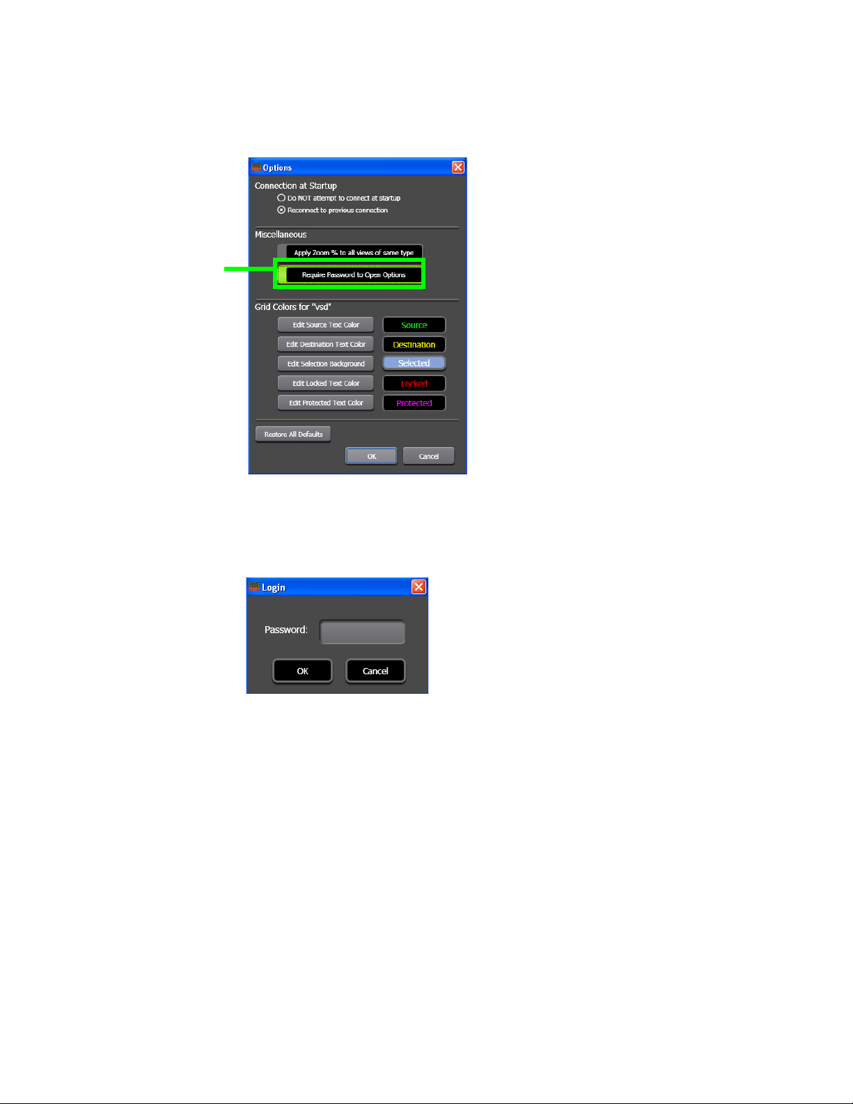
Section 4 — VSD Introduction
Require Password to Open
Options Button
Figure 72. Options Screen
A password must now be entered into the Login dialog to open the
Options dialog (
Figure 73. Login Dialog for VSD
This required password is the one that was set for the entire control
panel.
Figure 73).
66 JUPITER AccuSwitch Soft Panels and Visual Status Display Instruction Manual
Page 75

Hot Keys
Interface Views
There are a number of special “Hot” keys to help quickly navigate
around each view's table. The Hot keys table identifies these keys and
their function.
Table 8. Hot Keys and Functionality
Hot Key Function
Home Goes to first cell of current row.
Ctrl+End Goes to the last cell of table.
Ctrl+Home Goes to first cell of table.
Page Up Goes to first cell of the page.
Page Down Goes to last cell of the page.
End + “Arrow keys” If the current cell is empty, the cursor will jump to the first cell in direction of the
arrow (Up, Down, Left, and Right) from the current that is not empty or to the last
cell if all are empty.
If current cell is not empty, the cursor will jump to the last cell in direction of the
arrow from the current that is not empty or to the last cell if all are empty.
The VSD will also show the CM status using the following
JUPITER AccuSwitch Soft Panels and Visual Status Display Instruction Manual 67
Page 76

Section 4 — VSD Introduction
68 JUPITER AccuSwitch Soft Panels and Visual Status Display Instruction Manual
Page 77

VSD Installation
Distribution
The Visual Status Display (VSD) application is included on the Jupiter and
Compact Router Control System software CDs; it is also available for
download from the Grass Valley Support web site.
Requirements
PC Display Requirements
For proper display of VSD screens, the following settings are required:
Section 5
• A minimum resolution 1280 X 1024 and 32 -bit color PC monitor
setting is recommended.
• At least 13MB of PC hard disk space is required for each VSD application.
• The Settings/Control Panels/Display Properties/Appearance font
size should be set to Normal. Selecting Large or Extra Large Fonts
will cause display problems.
JUPITER AccuSwitch Soft Panels and Visual Status Display Instruction Manual 67
Page 78

Section 5 — VSD Installation
.NET Software Requirements
The PC running a VSD requires Microsoft.NET Framework software. NET
Framework 3.5 can be installed on the English versions of any of the fol
-
lowing operating systems:
• Microsoft Windows 2003 Server Service Pack 1 (SP1)
•Windows XP SP2.
Table 9. System Requirements for Installing .NET Framework 3.0
Processor Minimum 400 megahertz (MHz) Pentium processor
Recommended: 1 gigahertz (GHz) Pentium processor
RAM: Minimum: 96 megabytes (MB)
Recommended: 256 MB
Hard Disk Up to 500 MB of available space may be required.
Installation Drive The .NET Framework 3.5 default installation location is the PC’s system drive (the
drive that boots your system). Ensure at least 500 MB is available on the system drive.
68 JUPITER AccuSwitch Soft Panels and Visual Status Display Instruction Manual
Page 79
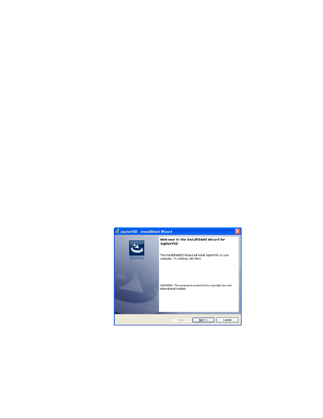
Installing VSD Using the VSD Installer
The following instructions show the steps needed to install the Visual
Status Display (VSD) application. The PC, which the VSD application is
installed on, must have network settings that allow communication with
the Jupiter or Prelude network. Consult with your Network administrator
for this information.
Follow these steps to begin installing the VSD application:
1. Insert the supplied software CDROM into the computer’s CD Drive
and follow the prompts.
Note The CD should automatically start the installation process. If not, browse to
the CD, using Window Explorer, and then click the setup.exe icon.
• If Microsoft .NET Framework was not installed earlier, you may see a
message asking if you want to install Microsoft .NET Framework. If so,
select “Yes.” The 3.5 version of .NET is located on the CD. Depending
on the OS version, the system may reboot automatically during this
process.
Installing VSD Using the VSD Installer
Note After an auto reboot, it may take several minutes for the system to display the
VSD installation welcome screen.
The Jupiter VSD Welcome screen will then appear (Figure 74).
Figure 74. Jupiter VSD Installer Welcome Screen
2. Click the Next> button to begin the installation process. The License
Agreement screen will then appear (Figure 75).
JUPITER AccuSwitch Soft Panels and Visual Status Display Instruction Manual 69
Page 80

Section 5 — VSD Installation
Figure 75. Jupiter VSD Installer License Agreement Screen
3. Click the I accept the terms in the License agreement radio button.
4. Click the Next> button to begin the installation process.
5. Follow the instructions on the following installation screens, click the
Next> button as needed (Figure 76).
Figure 76. Jupiter VSD Installation Screens
6. The Installed Wizard Completed screen will appear when the
installation process is finished (Figure 77).
70 JUPITER AccuSwitch Soft Panels and Visual Status Display Instruction Manual
Page 81

Installing VSD Using the VSD Installer
Figure 77. Installation Completed Screen
7. Click the Finish button. The Installation application will then close.
Jupiter VSD Desktop Icon
As part of the installation process a shortcut for the Jupiter VSD will be displayed on your PC’s desktop (Figure 78). Clicking this shortcut will launch
the installed soft panel. The Jupiter VSD must be configured to meet your
needs
Note See the Configuration Process section below for the configuration steps.
Figure 78. The Jupiter VSD Shortcut Example
Note The Jupiter VSD application will need to be configured with your Jupiter
AccuSwitch system before it will become operational (see Configuration
Process on page 75).
JUPITER AccuSwitch Soft Panels and Visual Status Display Instruction Manual 71
Page 82
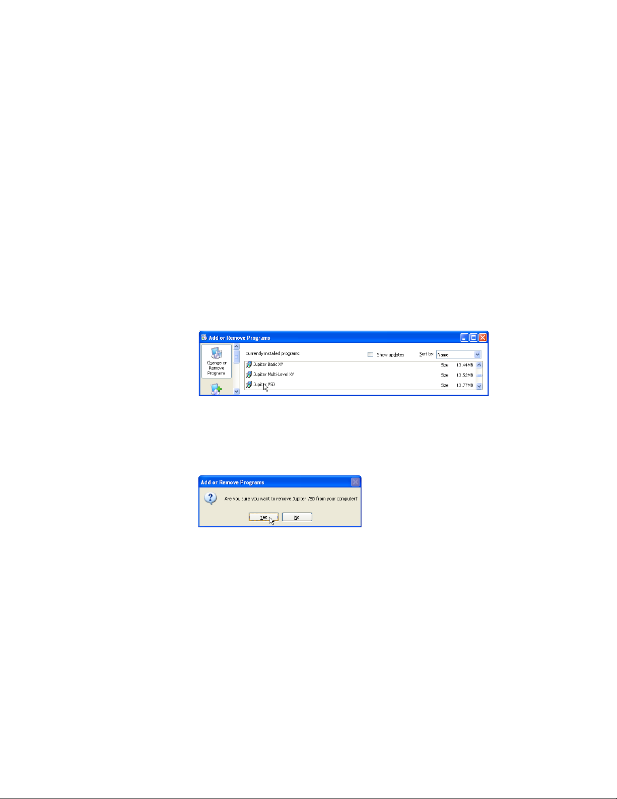
Section 5 — VSD Installation
Uninstall Process
Removing the VSD
The Jupiter VSD application can be removed using the Add Remove
Program feature (Control Panels> Add or Remove Programs) or the Instal
lation program that was used to install the VSD.
Using the Add Remove Program Feature
Follow these steps to remove the VSD from your computer:
1. Start the Add Remove Program feature (Control Panels> Add or
2. Select the VSD from the list of programs (Figure 79).
Figure 79. Example of the VSD in the List of Programs
-
Remove Programs).
3. Click the Remove button. The Add or Remove Programs dialog will then
appear (Figure 80).
Figure 80. The Jupiter VSD Shortcut Example
4. Click the Yes button.
The application will then be removed.
Using the Installation program
If the VSD application already exists on the PC when the installation
program is run, the Program Maintenance screen displays a Modify, Repair,
and Remove message (
changes to the VSD installation.
Figure 81). Clicking Next> allows you to make
Follow these steps to remove the VSD from your computer:
1. Select the Remove Radio button.
72 JUPITER AccuSwitch Soft Panels and Visual Status Display Instruction Manual
Page 83

Figure 81. Installation Modify, Repair, and Remove Screen
Uninstall Process
1. Click the Next button to make changes to the VSD installation. The
Remove the Program screen will then appear.
Figure 82. Remove the Program Screen
JUPITER AccuSwitch Soft Panels and Visual Status Display Instruction Manual 73
Page 84

Section 5 — VSD Installation
2. Click the Remove button. When the application is removed, the
InstallShield Wizard Completed screen will then appear.
Figure 83. Remove the Program Screen
3. Click the Finish button. The InstallShield Wizard Completed screen will
then close.
74 JUPITER AccuSwitch Soft Panels and Visual Status Display Instruction Manual
Page 85

Configuration Process
VSD PC IP Settings
The PC on which the Jupiter Visual Status Display (VSD) application is
installed, must have network settings that allow communication with the
Jupiter AccuSwitch Controller. Consult with your Network administrator
for this information.
Connecting to the Network
The Soft panel and VSD connect to the Network using one of two ports.
These ports are:
•Port 420
• A port number that is the Device ID added to 50000. For example, if the
Device ID is 21, the port number would be 50021.
Configuration Process
Note If the GUI panel is behind a firewall, the ports listed above will need to be
opened for the Soft panel and VSD to communicate with the AccuSwitch
Control module.
VSD Application Settings
During the following steps, you will need to know the IP address of the
primary AccuSwitch Controller (and the secondary, if it is installed) that
will be associated with the VSD. Use the Jupiter File Server JNS Control
Center application “Board Info” tab to determine the AccuSwitch Con
troller IP address (the Control Center application is described in the Jupiter
CM-4000 Installation and Operating manual).
1. Launch the VSD application. The main VSD screen (shown in Figure 84
on page 76) will open and the Router Connection Settings dialog will
then be displayed.
-
JUPITER AccuSwitch Soft Panels and Visual Status Display Instruction Manual 75
Page 86

Section 5 — VSD Installation
Figure 84. VSD Startup Display Example
• If the Router Connection Settings dialog is not open, select Router Connection from the File menu (File> Router Connection). The Router Connection Settings dialog will then appear.
Note Currently, the only selectable option for the Protocol list is ES-LAN.
Figure 85. Router Connection Settings Dialog
2. Enter a name for the settings for the router associated with this VSD in
the Settings Name field.
76 JUPITER AccuSwitch Soft Panels and Visual Status Display Instruction Manual
Page 87

Configuration Process
Note The maximum length allowed for a Settings name is 16 characters.
3. Click the System Connection (file Menu) button to add the System
Connections option to the File menu. This menu option provides a list
of available connections that have been saved and can be used to
connect to a server.
4. Select the preferred Protocol from the drop-down list. ES-LAN is the
only available option.
5. Enter the IP address of the AccuSwitch Controller associated with this
VSD in the Primary IP Address field.
6. Enter the IP address of the secondary AccuSwitch Controller (if
applicable) in the Secondary IP Address field.
7. Select a number between 1 and 64 for the Device ID field. This number
must be unique for panels associated with the same AccuSwitch
Controller. The Device ID is also entered on the MPK Devices table,
which is described in MPK Table Entries on page 18.
Note The Device ID number selected in the Device ID field corresponds to the MPK
table Address entry that uses two digit leading-zero numbers (01-09).
8. Select the IP address, if it is not already selected, from the PC IP
Address drop-down list.
9. Select the Connect button.
Clicking the Close Button Without Saving the Settings
The Save Network Connection(s) dialog (Figure 86 on page 78)will appear
if a new connection has been created or changes have been made to an
existing connection and the
settings have been saved.
The Save Network Connection(s) dialog will prompt you to save the
changes.
Close button is clicked before the connection
JUPITER AccuSwitch Soft Panels and Visual Status Display Instruction Manual 77
Page 88
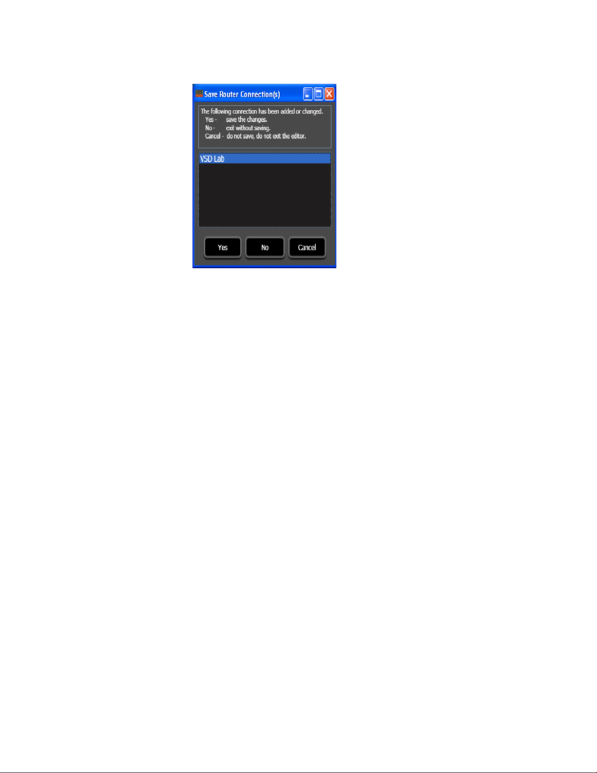
Section 5 — VSD Installation
Figure 86. The Save Network Connections) Dialog
• Click the Yes button to save the changes.
• Click the
the Router Connection Editor dialog without saving the changes. You
will no longer be prompted to save changes when you exit the program.
• Click the
and return to the Router Connection Editor dialog. However, no
changes will be saved.
Clicking the Connect Button Without Saving the Settings
The application will attempt to reconnect using the new or changed connection settings if you click the Connect button on the Router Connection
Editor dialog. These settings are temporary and will be lost if the applica
tion is closed and the setting changes were not saved.
User Preferences
The colors, the connection settings, and the size of the spreadsheet display
settings used on the VSD screen can be changed, if desired.
No button to close the Save Router Connection(s) dialog and
Cancel button to close the Save Network Connection(s) dialog
-
78 JUPITER AccuSwitch Soft Panels and Visual Status Display Instruction Manual
Page 89

Configuration Process
Follow these steps to set or change the preferences:
1. Go to “Options> Options”. The Options window will then appear
(Figure 87).
Figure 87. Options Window
2. Clicking any button in the Grid Colors section opens the Color window
(Figure 88).
Figure 88. Options Color Selection Screen
JUPITER AccuSwitch Soft Panels and Visual Status Display Instruction Manual 79
Page 90

Section 5 — VSD Installation
80 JUPITER AccuSwitch Soft Panels and Visual Status Display Instruction Manual
Page 91

VSD Procedures
VSD Procedures
This section describes the procedures or actions that you will use to check
the status of the Jupiter system.
Creating a View
You can create custom views where you can easily see the settings that you
wish to monitor. The custom view will allow you to see a router’s status
using different Levels, Outputs, or Groups. These steps are the same for
creating either the Destination view or the Sources view.
Section 6
Follow these steps to create a view:
1. Highlight the rows that you want to add to the custom view.
2. Click the Create View button or select the Create Custom View option from
the View... menu. The custom view will then be created, with the name
of the range of rows. For example, DST_10_19 would be used for the
Destinations rows 10 - 19.
3. The rows that you copied will be in the view. The title for the first data
column will added after the type of rows have been copied. For
example, “Destinations” or “Sources,” Figure 89 on page 82 shows
Destination examples.
JUPITER AccuSwitch Soft Panels and Visual Status Display Instruction Manual 81
Page 92

Section 6 — VSD Procedures
Figure 89. Custom View
Closing a View
You can close a custom view by clicking the Close View button or selecting
the Close Custom View option from the View menu (View> Close Current
View).
Opening a View
You can open a custom view if it has been closed.
Follow these steps to open a view:
1. Click the Open View button or select the Open Custom View. . . option from
Three buttons can now be seen. These buttons are, Hide Mode, Unhide Cols,
Hide Cols. These buttons add to the ability to customize a view by
and
hiding selected columns. Only columns can be hidden. For more infor
mation see the Using the Hide Mode on page 85 section
the View menu (View> Open Custom View. . .). The Open Custom View
window will then appear.
-
82 JUPITER AccuSwitch Soft Panels and Visual Status Display Instruction Manual
Page 93

Figure 90. The Open Custom View Window
2. Select the view you want to open.
3. Click the Ok button. The view you selected will then appear.
Copying and Pasting a Row
VSD Procedures
You can add information to an existing Custom view using the Copy and
Paste features.
Follow these steps to Copy and Paste information:
1. Highlight the rows that you want to add to the custom view (Figure 91).
2. Click the Copy Rows button.
Figure 91. Copied Row
JUPITER AccuSwitch Soft Panels and Visual Status Display Instruction Manual 83
Page 94
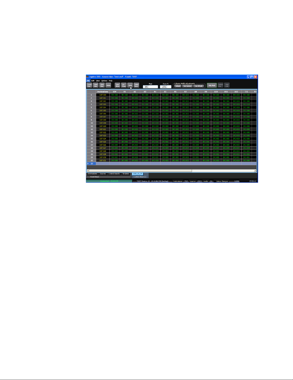
Section 6 — VSD Procedures
3. Open the view that you want to past the row into.
4. Highlight the row that you want to paste the information into.
5. Click the Paste button (Figure 92).
Figure 92. Pasting the Row
6. The rows that you copied and pasted will then be in the view.
Deleting a Row
You can delete rows from an existing view.
Follow these steps to delete a row:
1. Highlight the rows that you want to delete.
2. Click the Delete button (Figure 93 on page 85).
Rows can also be cut from a custom view and pasted into another view
using the above described steps.
84 JUPITER AccuSwitch Soft Panels and Visual Status Display Instruction Manual
Page 95
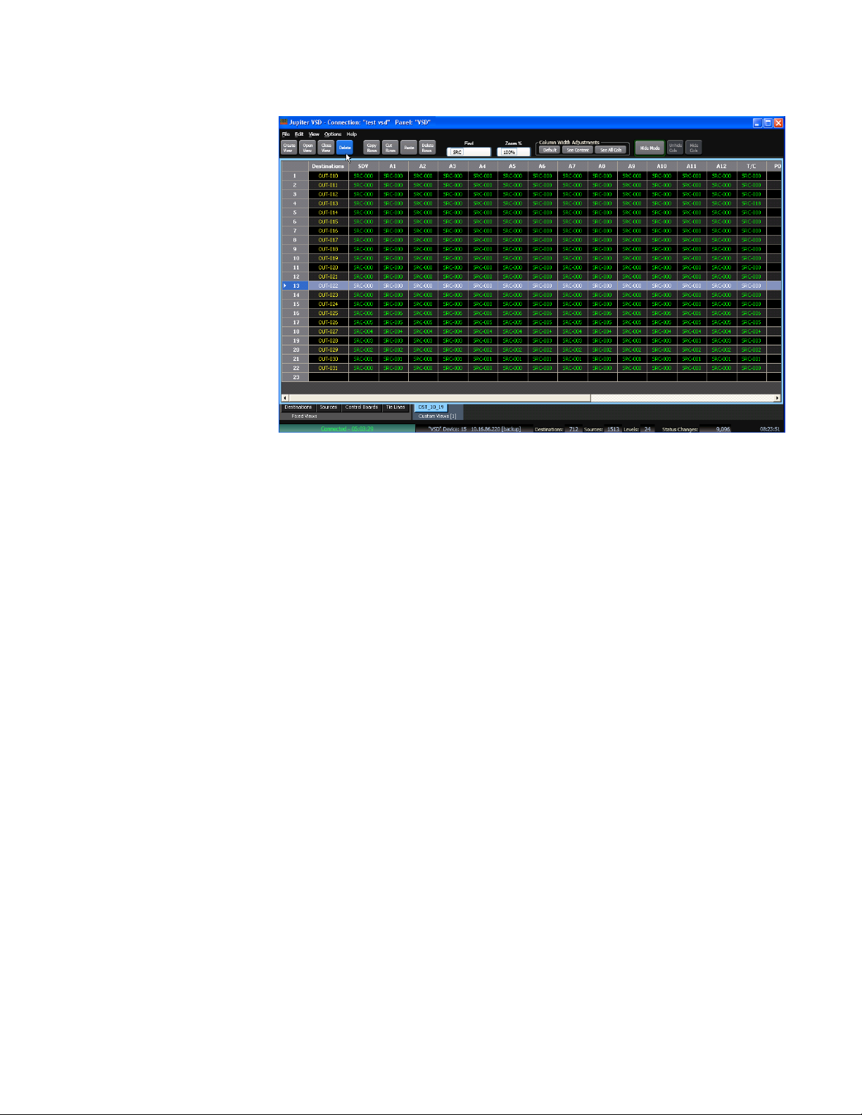
Figure 93. Deleting the Row
VSD Procedures
3. The row or rows you selected will then be deleted from the view.
Using the Search Field
You can search for information or text by entering that information into the
Find field.
Follow these steps to use the search feature:
1. Enter the text that you want to search for into the Find field.
2. Press the F3 key on your keyboard. The VSD application will then
attempt to find the first occurrence of the text shown in the Find field
(Figure 94 on page 86).
Using the Hide Mode
You can hide columns to help see the information that you need to see.
Follow these steps to use the Hide Mode:
1. Click the Hide Mode button.
2. Select the columns that you want to hide.
3. Click the Hide Cols button (Figure 94 on page 86).
JUPITER AccuSwitch Soft Panels and Visual Status Display Instruction Manual 85
Page 96

Section 6 — VSD Procedures
Figure 94. The Hide Mode Feature
Note The first column (column 0), the “destinations” column in Figure 94 cannot
be hidden or selected.
Adjusting the Column Width
You can adjust the column widths, which will help you to see all the information that you need. You can adjust a single column, Adjust the column
to see the content of the view, or adjust the column to see all columns within
the view.
Adjusting a Single Column
Follow these steps to adjust a single column:
1. Highlight the column that you want to adjust.
2. Place the cursor by a column heading, until the cursor changes into a
double-arrow.
3. Drag the edge of the columns to the width that you desire (Figure 95 on
page 87).
86 JUPITER AccuSwitch Soft Panels and Visual Status Display Instruction Manual
Page 97

Figure 95. The Hide Mode Feature
VSD Procedures
The column’s width will be changed.
Seeing All the Columns
Follow these steps to see all the columns:
1. Click the See All Cols button (Figure 96).
2. All the columns will then be visible.
Figure 96. The “See All Cols” Feature
JUPITER AccuSwitch Soft Panels and Visual Status Display Instruction Manual 87
Page 98

Section 6 — VSD Procedures
Seeing All of the Content
Follow these steps to see all of the content:
1. Click the See Content button (Figure 97).
2. All the content will then be visible.
Figure 97. The “See Content” Feature
Changing the Zoom Percentage
You can change the display size so that the status can be read from different
distances by modifying the zoom percentage.
Follow these steps to change the “Zoom” percentage:
1. Select the Zoom% field.
2. Click within the Zoom% field and select the desired percentage. In the
example that is shown in Figure 98 on page 89, the 200% option was
selected.
88 JUPITER AccuSwitch Soft Panels and Visual Status Display Instruction Manual
Page 99

Figure 98. Zoom% at 200
VSD Procedures
The view is then set to the desired percent.
Setting the Zoom% to all Views of the Same Type
You can apply the Zoom percentage to all of the views that are same type.
Follow these steps to apply the Zoom percentage to all of the views:
1. Open the Options dialog in the Options menu (Menu bar: Options>
Options). The Options dialog will then appear.
2. Click the “Apply Zoom% to all views of same type” button (Figure 99).
Figure 99. The Apply Zoom% To All Views Of Same Type Button
JUPITER AccuSwitch Soft Panels and Visual Status Display Instruction Manual 89
Page 100

Section 6 — VSD Procedures
Selected
Locked Cells
Using the Force Unlock Option
3. Click the OK button.
The Zoom percentage will then be applied.
The VSD can force unlock any destination regardless of what panel locked
or protected it. In order for Force Unlock to be enabled, the VSD must be
defined with a password of 90 – 99 in MPK Devices table of the Jupiter
Editor. The
90-99 and a locked/protected cell has been selected.
Note If AccuSwitch or Jupiter locks or protects a Destination on a 3rd party router
Follow these steps to use the Force Unlock option:
Force Unlock button will only be enabled if the password is set to
that is shared with another control system, there is the possibility that after a
pmemClear command occurs on the AccuSwitch/Jupiter Control system that
the destination will report as being locked or protected by the 3rd party’s
control system. This Destination will have to be Force unlocked by an AccuSwitch/Jupiter Control system with Force Unlock privileges to regain control
of the Destination.
1. Select the Locked cells (Figure 100).
Figure 100. Selected Tie Line
2. Click the Force unlock button.
The destinations will no longer be locked.
90 JUPITER AccuSwitch Soft Panels and Visual Status Display Instruction Manual
Clearing Tie Lines
Tie Lines or the connections between routers can be replaced using the Clear
Selected Tie Lines
button (Figure 101).
 Loading...