

Page 1

JEP Series
Jupiter / Encore Control Panels
Installation Manual
Software Version 1.3.0
071837202
SEPTEMBER 2011
Page 2

CERTIFICATE
Certificate Number: 510040.001
The Quality System of:
Grass Valley USA, LLC and its Grass Valley Affiliates
Headquarters:
400 Providence Mine Road
Nevada City, CA 95945
United States
15655 SW Greystone Ct.
Beaverton, OR 97006
United States
Brunnenweg 9
D-64331 Weiterstadt
Germany
Kapittelweg 10
4827 HG Breda
The Nederlands
2300 So. Decker Lake Blvd.
Salt Lake City, UT 84119
United States
Including its implementation, meets the requirements of the standard:
ISO 9001:2008
Scope:
The design, manufacture and support of video and audio hardware and software products and related
systems.
This Certificate is valid until: June 14, 2012
This Certificate is valid as of: December 23, 2010
Certified for the first time: June 14, 2000
H. Pierre Sallé
President
KEMA-Registered Quality
The method of operation for quality certification is defined in the KEMA General Terms And Conditions For
Quality And Environmental Management Systems Certifications. Integral publication of this certificate is allowed.
KEMA-Registered Quality, Inc.
4377 County Line Road
Chalfont, PA 18914
Ph: (215)997-4519
Fax: (215)997-3809
CRT 001 042108
ccredited By:
ANAB
A
Page 3

JEP Series
Jupiter / Encore Control Panels
Installation Manual
Software Version 1.3.0
071837202
SEPTEMBER 2011
Page 4

Contacting Grass Valley
International
Support Centers
Local Support
Centers
(available
during normal
business hours)
France
24 x 7
Australia and New Zealand: +61 1300 721 495 Central/South America: +55 11 5509 3443
Middle East: +971 4 299 64 40 Near East and Africa: +800 8080 2020 or +33 1 48 25 20 20
Europe
+800 8080 2020 or +33 1 48 25 20 20
Hong Kong, Taiwan, Korea, Macau: +852 2531 3058 Indian Subcontinent: +91 22 24933476
Asia
Southeast Asia/Malaysia: +603 7805 3884 Southeast Asia/Singapore: +65 6379 1313
China: +861 0660 159 450 Japan: +81 3 5484 6868
Belarus, Russia, Tadzikistan, Ukraine, Uzbekistan: +7 095 2580924 225 Switzerland: +41 1 487 80 02
S. Europe/Italy-Roma: +39 06 87 20 35 28 -Milan: +39 02 48 41 46 58 S. Europe/Spain: +34 91 512 03 50
Benelux/Belgium: +32 (0) 2 334 90 30 Benelux/Netherlands: +31 (0) 35 62 38 42 1 N. Europe: +45 45 96 88 70
Germany, Austria, Eastern Europe: +49 6150 104 444 UK, Ireland, Israel: +44 118 923 0499
Copyright © Grass Valley USA, LLC. All rights reserved.
This product may be covered by one or more U.S. and foreign patents.
United States/Canada
24 x 7
+1 800 547 8949 or +1 530 478 4148
Grass Valley Web Site
The www.grassvalley.com web site offers the following:
Online User Documentation — Current versions of product catalogs, brochures,
data sheets, ordering guides, planning guides, manuals, and release notes
in .pdf format can be downloaded.
FAQ Database — Solutions to problems and troubleshooting efforts can be
found by searching our Frequently Asked Questions (FAQ) database.
Software Downloads — Download software updates, drivers, and patches.
4 JEP Series — Installation Manual
Page 5

Contents
Preface. . . . . . . . . . . . . . . . . . . . . . . . . . . . . . . . . . . . . . . . . . . . . . . . . . . . . . . . . . . . . . . . . . . . . 9
Regulatory Notices
Safety Summary
About This Manual . . . . . . . . . . . . . . . . . . . . . . . . . . . . . . . . . . . . . . . . . . . . . . . . . . . . . 9
Additional Documentation . . . . . . . . . . . . . . . . . . . . . . . . . . . . . . . . . . . . . . . . . . . . 9
Certifications and Compliances . . . . . . . . . . . . . . . . . . . . . . . . . . . . . . . . . . . . . . . . . 11
FCC Emission Control . . . . . . . . . . . . . . . . . . . . . . . . . . . . . . . . . . . . . . . . . . . . . . . 11
Canadian EMC Notice of Compliance . . . . . . . . . . . . . . . . . . . . . . . . . . . . . . . . . . 11
EN55022 Class A Warning . . . . . . . . . . . . . . . . . . . . . . . . . . . . . . . . . . . . . . . . . . . . 11
Canadian Certified Power Cords . . . . . . . . . . . . . . . . . . . . . . . . . . . . . . . . . . . . . . 12
Canadian Certified AC Adapter . . . . . . . . . . . . . . . . . . . . . . . . . . . . . . . . . . . . . . . 12
Laser Compliance . . . . . . . . . . . . . . . . . . . . . . . . . . . . . . . . . . . . . . . . . . . . . . . . . . . 12
Laser Safety Requirements . . . . . . . . . . . . . . . . . . . . . . . . . . . . . . . . . . . . . . . . . . 12
Laser Safety. . . . . . . . . . . . . . . . . . . . . . . . . . . . . . . . . . . . . . . . . . . . . . . . . . . . . . . 12
FCC Emission Limits . . . . . . . . . . . . . . . . . . . . . . . . . . . . . . . . . . . . . . . . . . . . . . . 13
Certifications: . . . . . . . . . . . . . . . . . . . . . . . . . . . . . . . . . . . . . . . . . . . . . . . . . . . . . . . 13
Safety Terms and Symbols. . . . . . . . . . . . . . . . . . . . . . . . . . . . . . . . . . . . . . . . . . . . . . 15
Terms in This Manual . . . . . . . . . . . . . . . . . . . . . . . . . . . . . . . . . . . . . . . . . . . . . . . . 15
Terms on the Product . . . . . . . . . . . . . . . . . . . . . . . . . . . . . . . . . . . . . . . . . . . . . . . . 15
Symbols on the Product . . . . . . . . . . . . . . . . . . . . . . . . . . . . . . . . . . . . . . . . . . . . . . 16
Warnings . . . . . . . . . . . . . . . . . . . . . . . . . . . . . . . . . . . . . . . . . . . . . . . . . . . . . . . . . . . . 16
Cautions . . . . . . . . . . . . . . . . . . . . . . . . . . . . . . . . . . . . . . . . . . . . . . . . . . . . . . . . . . . . . 17
ESD Protection
Recommended ESD Guidelines . . . . . . . . . . . . . . . . . . . . . . . . . . . . . . . . . . . . . . . . . 19
Sources of ESD and Risks. . . . . . . . . . . . . . . . . . . . . . . . . . . . . . . . . . . . . . . . . . . . . . . 20
Grounding Requirements for Personnel . . . . . . . . . . . . . . . . . . . . . . . . . . . . . . . . . . 21
Section 1 — JEP-100 Control Panel . . . . . . . . . . . . . . . . . . . . . . . . . . . . . . . . . . . . 23
Introduction . . . . . . . . . . . . . . . . . . . . . . . . . . . . . . . . . . . . . . . . . . . . . . . . . . . . . . . . . . 23
Specifications . . . . . . . . . . . . . . . . . . . . . . . . . . . . . . . . . . . . . . . . . . . . . . . . . . . . . . . 24
Hardware Installation - Jupiter System . . . . . . . . . . . . . . . . . . . . . . . . . . . . . . . . . . . 25
LAN Only System . . . . . . . . . . . . . . . . . . . . . . . . . . . . . . . . . . . . . . . . . . . . . . . . . . . 26
Serial System . . . . . . . . . . . . . . . . . . . . . . . . . . . . . . . . . . . . . . . . . . . . . . . . . . . . . . . 27
LAN + Serial System . . . . . . . . . . . . . . . . . . . . . . . . . . . . . . . . . . . . . . . . . . . . . . . . . 28
Serial Data Cables . . . . . . . . . . . . . . . . . . . . . . . . . . . . . . . . . . . . . . . . . . . . . . . . . . . 29
VDE Modifications to Serial Data Cables. . . . . . . . . . . . . . . . . . . . . . . . . . . . . . 30
Joystick Override . . . . . . . . . . . . . . . . . . . . . . . . . . . . . . . . . . . . . . . . . . . . . . . . . . . . 30
Internet Protocol Configuration . . . . . . . . . . . . . . . . . . . . . . . . . . . . . . . . . . . . . . . . . 31
Single Network IP Configuration . . . . . . . . . . . . . . . . . . . . . . . . . . . . . . . . . . . . . . 31
LAN Only System . . . . . . . . . . . . . . . . . . . . . . . . . . . . . . . . . . . . . . . . . . . . . . . . . 32
Serial System. . . . . . . . . . . . . . . . . . . . . . . . . . . . . . . . . . . . . . . . . . . . . . . . . . . . . . 33
LAN + Serial System . . . . . . . . . . . . . . . . . . . . . . . . . . . . . . . . . . . . . . . . . . . . . . . 34
Software Installation Process. . . . . . . . . . . . . . . . . . . . . . . . . . . . . . . . . . . . . . . . . . . . 35
Installing the Latest Software Version to the PC . . . . . . . . . . . . . . . . . . . . . . . . . 35
Updating to the Latest Software Version . . . . . . . . . . . . . . . . . . . . . . . . . . . . . . . . . 38
JEP Series — Installation Manual 5
Page 6

— Contents
Using the Network Download Utility . . . . . . . . . . . . . . . . . . . . . . . . . . . . . . . . . . 38
Using the Update Manager . . . . . . . . . . . . . . . . . . . . . . . . . . . . . . . . . . . . . . . . . 39
Updating the JEP-100 panel Using NetConfig. . . . . . . . . . . . . . . . . . . . . . . . . . . . . 45
IP Configuration Procedure. . . . . . . . . . . . . . . . . . . . . . . . . . . . . . . . . . . . . . . . . 46
Multi-Network IP Configuration . . . . . . . . . . . . . . . . . . . . . . . . . . . . . . . . . . . . . . . . 49
Configuration - Jupiter System. . . . . . . . . . . . . . . . . . . . . . . . . . . . . . . . . . . . . . . . . . 50
LAN Only System. . . . . . . . . . . . . . . . . . . . . . . . . . . . . . . . . . . . . . . . . . . . . . . . . . . 50
MPK Table Entries. . . . . . . . . . . . . . . . . . . . . . . . . . . . . . . . . . . . . . . . . . . . . . . . . 51
Serial System . . . . . . . . . . . . . . . . . . . . . . . . . . . . . . . . . . . . . . . . . . . . . . . . . . . . . . . 53
Serial Protocol Table Entries . . . . . . . . . . . . . . . . . . . . . . . . . . . . . . . . . . . . . . . . 53
MPK Table Entries. . . . . . . . . . . . . . . . . . . . . . . . . . . . . . . . . . . . . . . . . . . . . . . . . 54
Special Entries Needed to Upgrade Serial Panels . . . . . . . . . . . . . . . . . . . . . . 55
LAN + Serial System . . . . . . . . . . . . . . . . . . . . . . . . . . . . . . . . . . . . . . . . . . . . . . . . 56
Serial Protocol Table Entries . . . . . . . . . . . . . . . . . . . . . . . . . . . . . . . . . . . . . . . . 56
MPK Table Entries. . . . . . . . . . . . . . . . . . . . . . . . . . . . . . . . . . . . . . . . . . . . . . . . . 57
Special Entries Needed to Upgrade Serial Panels . . . . . . . . . . . . . . . . . . . . . . 58
All Systems. . . . . . . . . . . . . . . . . . . . . . . . . . . . . . . . . . . . . . . . . . . . . . . . . . . . . . . . . 59
Control Panel Sets . . . . . . . . . . . . . . . . . . . . . . . . . . . . . . . . . . . . . . . . . . . . . . . . . 59
Audio Mode (Special Stereo Switching) . . . . . . . . . . . . . . . . . . . . . . . . . . . . . . 59
Salvo Switching . . . . . . . . . . . . . . . . . . . . . . . . . . . . . . . . . . . . . . . . . . . . . . . . . . . 59
Compiling. . . . . . . . . . . . . . . . . . . . . . . . . . . . . . . . . . . . . . . . . . . . . . . . . . . . . . . . 60
Section 2 — JEP-100 CP Operation . . . . . . . . . . . . . . . . . . . . . . . . . . . . . . . . . . . . 61
LED Displays. . . . . . . . . . . . . . . . . . . . . . . . . . . . . . . . . . . . . . . . . . . . . . . . . . . . . . . 61
Show Button Assignment . . . . . . . . . . . . . . . . . . . . . . . . . . . . . . . . . . . . . . . . . . . . 62
Destination Selection / Status Check. . . . . . . . . . . . . . . . . . . . . . . . . . . . . . . . . . . 62
Source Selection (All Levels Take) . . . . . . . . . . . . . . . . . . . . . . . . . . . . . . . . . . . . . 63
BPS button programming . . . . . . . . . . . . . . . . . . . . . . . . . . . . . . . . . . . . . . . . . . 63
Level Breakaways (Split Switching). . . . . . . . . . . . . . . . . . . . . . . . . . . . . . . . . . . . 64
Default Mode Breakaway. . . . . . . . . . . . . . . . . . . . . . . . . . . . . . . . . . . . . . . . . . . 64
Button-per-Level Mode Breakaway . . . . . . . . . . . . . . . . . . . . . . . . . . . . . . . . . . . . 65
Checking Status of Selected Level . . . . . . . . . . . . . . . . . . . . . . . . . . . . . . . . . . . 65
Defining a Source Button. . . . . . . . . . . . . . . . . . . . . . . . . . . . . . . . . . . . . . . . . . . . . 66
Defining a Destination Button . . . . . . . . . . . . . . . . . . . . . . . . . . . . . . . . . . . . . . . . 68
Defining a Level Button . . . . . . . . . . . . . . . . . . . . . . . . . . . . . . . . . . . . . . . . . . . . . . 69
Locking or Unlocking an Output . . . . . . . . . . . . . . . . . . . . . . . . . . . . . . . . . . . . . . 70
Salvo Switching . . . . . . . . . . . . . . . . . . . . . . . . . . . . . . . . . . . . . . . . . . . . . . . . . . . . . 71
Setting Up a Sequence . . . . . . . . . . . . . . . . . . . . . . . . . . . . . . . . . . . . . . . . . . . . . 71
Executing a Sequence . . . . . . . . . . . . . . . . . . . . . . . . . . . . . . . . . . . . . . . . . . . . . . 72
Assigning a Sequence to a Button. . . . . . . . . . . . . . . . . . . . . . . . . . . . . . . . . . . . 72
Joystick Override. . . . . . . . . . . . . . . . . . . . . . . . . . . . . . . . . . . . . . . . . . . . . . . . . . . . 73
Configuring a JEP-100 GPI Port (Joystick Override Control Line) . . . . . . . . . . 76
Menu Functions. . . . . . . . . . . . . . . . . . . . . . . . . . . . . . . . . . . . . . . . . . . . . . . . . . . . . 77
AlM. - Alternate Mode . . . . . . . . . . . . . . . . . . . . . . . . . . . . . . . . . . . . . . . . . . . . . 77
SelAMod. - Select Audio Mode (Special Stereo Switching) . . . . . . . . . . . . . . 79
DspAMod. - Display Audio Mode (Special Stereo Switching) . . . . . . . . . . . 80
Locking or Unlocking an Output . . . . . . . . . . . . . . . . . . . . . . . . . . . . . . . . . . . . 81
M.O. - Multiple Output Mode On/Off . . . . . . . . . . . . . . . . . . . . . . . . . . . . . . . 81
ELAN - Ethernet Mode On/Off . . . . . . . . . . . . . . . . . . . . . . . . . . . . . . . . . . . . . 82
D.T. - Display Time On/Off . . . . . . . . . . . . . . . . . . . . . . . . . . . . . . . . . . . . . . . . 82
Chg ID - Change Panel ID Mode . . . . . . . . . . . . . . . . . . . . . . . . . . . . . . . . . . . . 82
v - Version Number Display . . . . . . . . . . . . . . . . . . . . . . . . . . . . . . . . . . . . . . . . 82
Internet Protocol Address Display . . . . . . . . . . . . . . . . . . . . . . . . . . . . . . . . . . . 82
6 JEP Series — Installation Manual
Page 7

Diag - Diagnostic Mode . . . . . . . . . . . . . . . . . . . . . . . . . . . . . . . . . . . . . . . . . . . . 83
C.B. - Change Brightness. . . . . . . . . . . . . . . . . . . . . . . . . . . . . . . . . . . . . . . . . . . . 83
Output Button Assignment . . . . . . . . . . . . . . . . . . . . . . . . . . . . . . . . . . . . . . . . . 83
Password Protection . . . . . . . . . . . . . . . . . . . . . . . . . . . . . . . . . . . . . . . . . . . . . . . 84
Disabling the Configuration and Setup Menus. . . . . . . . . . . . . . . . . . . . . . . . . 85
INDEX . . . . . . . . . . . . . . . . . . . . . . . . . . . . . . . . . . . . . . . . . . . . . . . . . . . . . . . . . . . . . . . . . . . . . . 1
JEP Series — Installation Manual 7
Page 8

— Contents
8 JEP Series — Installation Manual
Page 9

Preface
About This Manual
This manual provides installation and operating information for the JEP control
panel series. These control panels are designed for use with a Jupiter CM-
4000 or CM-4400 System Controller.
Additional Documentation
Printed and electronic copies of this manual are normally provided with
the system. Individual manuals may be ordered by contacting Technical
Support. For contact information, see
Configuration information for the Jupiter control system itself is contained
in the control system’s documentation set:
Contacting Grass Valley on page 4.
Jupiter Control System Release Notes.
Jupiter CM-4000 Installation and Operating Manual
Jupiter CM-4400 Installation and Operating Manual
Jupiter Getting Started Guide.
Electronic copies of other routing products documents are available on the
following documentation CDs:
Routing Products Documentation CD. Includes all Jupiter manuals.
These documents are also available on the www.grassvalley.com web site.
JEP Series — Installation Manual 9
Page 10

Preface
10 JEP Series — Installation Manual
Page 11

Regulatory Notices
Certifications and Compliances
FCC Emission Control
This equipment has been tested and found to comply with the limits for a
Class A digital device, pursuant to Part 15 of the FCC Rules. These limits
are designed to provide reasonable protection against harmful interference
when the equipment is operated in a commercial environment. This equip
ment generates, uses, and can radiate radio frequency energy and, if not
installed and used in accordance with the instruction manual, may cause
harmful interference to radio communications. Operation of this equip
ment in a residential area is likely to cause harmful interference in which
case the user will be required to correct the interference at his own expense.
Changes or modifications not expressly approved by Grass Valley Group
can affect emission compliance and could void the user’s authority to
operate this equipment.
-
-
Canadian EMC Notice of Compliance
This digital apparatus does not exceed the Class A limits for radio noise
emissions from digital apparatus set out in the Radio Interference Regula
tions of the Canadian Department of Communications.
Le présent appareil numérique n’emet pas de bruits radioélectriques
dépassant les limites applicables aux appareils numeriques de la classe A
préscrites dans le Règlement sur le brouillage radioélectrique édicte par le
ministère des Communications du Canada.
EN55022 Class A Warning
In a domestic environment, products that comply with Class A may cause
radio interference in which case the user may be required to take adequate
measures.
-
JEP Series — Installation Manual 11
Page 12

Regulatory Notices
Canadian Certified Power Cords
Canadian Certified AC Adapter
Laser Compliance
Laser Safety Requirements
Canadian approval includes the products and power cords appropriate for
use in the North America power network. All other power cords supplied
are approved for the country of use.
Canadian approval includes the AC adapters appropriate for use in the
North America power network. All other AC adapters supplied are
approved for the country of use.
The device used in this product is a Class 1 certified laser product. Operating this product outside specifications or altering from its original design
may result in hazardous radiation exposure, and may be considered an act
of modifying or new manufacturing of a laser product under U.S. regula
tions contained in 21CFR Chapter 1, subchapter J or CENELEC regulations
in HD 482 S1. People performing such an act are required by law to recertify
and reidentify this product in accordance with provisions of 21CFR sub
chapter J for distribution within the U.S.A., and in accordance with
CENELEC HD 482 S1 for distribution within countries using the IEC 825
standard.
-
-
Laser Safety
Laser safety in the United States is regulated by the Center for Devices and
Radiological Health (CDRH). The laser safety regulations are published in
the “Laser Product Performance Standard,” Code of Federal Regulation
(CFR), Title 21, Subchapter J.
The International Electrotechnical Commission (IEC) Standard 825, “Radiation of Laser Products, Equipment Classification, Requirements and
User’s Guide,” governs laser products outside the United States. Europe
and member nations of the European Free Trade Association fall under the
jurisdiction of the Comite European de Normalization Electrotechnique
(CENELEC).
For the CDRH: The radiant power is detected through a 7 mm aperture at
a distance of 200 mm from the source focused through a lens with a focal
length of 100 mm.
For IEC compliance: The radiant power is detected through a 7 mm aperture at a distance of 100 mm from the source focused through a lens with a
focal length of 100 mm.
12 JEP Series — Installation Manual
Page 13

FCC Emission Limits
Certifications:
Category Standard Designed/tested for compliance with:
Safety
EMI
Regulatory Notices
This device complies with Part 15 of the FCC Rules. Operation is subject to
the following two conditions: (1) This device may not cause harmful inter
ference, and (2) this device must accept any interference received,
including interference that may cause undesirable operation. This device
has been tested and found to comply with FCC Part 15 Class B limits for a
digital device when tested with a representative laser-based fiber optical
system that complies with ANSI X3T11 Fiber Channel Standard.
ANSI / UL60950 “Standard for Safety of Information Technology Equipment - Safety - Part 1: General
IEC 60950 “Standard for Safety for Information Technology Equipment - Safety - Part 1: General
CAN/CSA C22.2, No. 60950 “Standard for Safety of Information Technology Equipment - Safety - Part 1: General
EN60950 Safety of Information Technology Equipment, including Electrical Business Equipment.
73/23/EEC Low Voltage Directive
EMC Directive 89/336/EEC via
EN 55103-1 and 2
EN 55103-1 standards Electromagnetic compatibility.
EN55103-2 standards Electromagnetic compatibility--Product family standard for audio, video, audio-visual
US FCC Class A
Canada FCC Industry Canada
Australia & New Zealand: AS/NZS 3548
Requirements”, (ANSI/UL 60950-1, First Edition, Dated April 1, 2003, with revision
through and including November 26, 2003.)
Requirements”, (IEC 60950-1, First Edition, 2001, Corrigendum 1:10-2002)
Requirements”, (CAN/CSA-C22.2 No. 60950-1-03. First Edition Dated April 1, 2003,
with revisions through and including November 26, 2003)
Audio, Video and Entertainment Lighting Control for the European Community.
Product family standard for audio, video, audio-visual and entertainment lighting control
apparatus for professional use.
Part 1 Emissions, Environment E1/E2
EN 55022: Class A Radiated and Conducted Emissions
EN 61000-3-2: Power Line Harmonic Emissions, Radiated Magnetic Field Emissions,
Peak Inrush Current
and entertainment lighting control apparatus for professional use.
Part 2 Immunity, Environment E1/E2
EN 50082-1: Immunity
EN 61000-4-2:
Electrostatic Discharge “ESD” Immunity
EN 61000-4-3:
Radiated RF Electromagnetic Field Immunity
EN 61000-4-4:
Electrical Fast Transient/Burst “EFT” Immunity
EN 61000-4-5: Surge Immunity
EN 61000-4-6: Conducted RF Immunity
EN 61000-4-11: Voltage Dips, Short Interruptions and Voltage Variations
Annex A - Radiated Magnetic Field Immunity
Note: This only applies to assemblies sensitive to magnetic fields
CISPR Pub. 22 (1985)
-
JEP Series — Installation Manual 13
Page 14

Regulatory Notices
14 JEP Series — Installation Manual
Page 15

Safety Summary
Read and follow the important safety information below, noting especially
those instructions related to risk of fire, electric shock or injury to persons.
Additional specific warnings not listed here may be found throughout the
manual.
WARNING Any instructions in this manual that require opening the equipment cover
or enclosure are for use by qualified service personnel only. To reduce the
risk of electric shock, do not perform any servicing other than that contained in the operating instructions unless you are qualified to do so.
Safety Terms and Symbols
Terms in This Manual
Safety-related statements may appear in this manual in the following form:
WARNING Warning statements identify conditions or practices that may result in per-
sonal injury or loss of life.
CAUTION Caution statements identify conditions or practices that may result in damage
to equipment or other property, or which may cause equipment crucial to
your business environment to become temporarily non-operational.
Terms on the Product
The following terms may appear on the product:
DANGER — A personal injury hazard is immediately accessible as you read
the marking.
WARNING — A personal injury hazard exists but is not immediately acces-
sible as you read the marking.
CAUTION — A hazard to property, product, and other equipment is present.
JEP Series — Installation Manual 15
Page 16
Safety Summary
Symbols on the Product
The following symbols may appear on the product:
Indicates that dangerous high voltage is present within the
equipment enclosure that may be of sufficient magnitude to
constitute a risk of electric shock.
Indicates that user, operator or service technician should refer
to product manual(s) for important operating, maintenance,
or service instructions.
This is a prompt to note fuse rating when replacing fuse(s).
The fuse referenced in the text must be replaced with one
having the ratings indicated.
Identifies a protective grounding terminal which must be connected to earth ground prior to making any
connections.
other equipment
Warnings
Identifies an external protective grounding terminal which
may be connected to earth ground as a supplement to an
internal grounding terminal.
Indicates that static sensitive components are present which
may be damaged by electrostatic discharge. Use anti-static
procedures, equipment and surfaces during servicing.
The following warning statements identify conditions or practices that can
result in personal injury or loss of life.
Dangerous voltage or current may be present — Disconnect power and remove
battery (if applicable) before removing protective panels, soldering, or
replacing components.
Do not service alone — Do not internally service this product unless another
person capable of rendering first aid and resuscitation is present.
Remove jewelry — Prior to servicing, remove jewelry such as rings, watches,
and other metallic objects.
Avoid exposed circuitry — Do not touch exposed connections, components or
circuitry when power is present.
16 JEP Series — Installation Manual
Page 17

Safety Summary
Use proper power cord — Use only the power cord supplied or specified for
this product.
Ground product — Connect the grounding conductor of the power cord to
earth ground.
Operate only with covers and enclosure panels in place — Do not operate this
product when covers or enclosure panels are removed.
Use correct fuse — Use only the fuse type and rating specified for this
product.
Use only in dry environment — Do not operate in wet or damp conditions.
Use only in non-explosive environment — Do not operate this product in an
explosive atmosphere.
High leakage current may be present — Earth connection of product is essential
before connecting power.
Dual power supplies may be present — Be certain to plug each power supply
cord into a separate branch circuit employing a separate service ground.
Disconnect both power supply cords prior to servicing.
Cautions
Double pole neutral fusing — Disconnect mains power prior to servicing.
Use proper lift points — Do not use door latches to lift or move equipment.
Avoid mechanical hazards — Allow all rotating devices to come to a stop before
servicing.
The following caution statements identify conditions or practices that can
result in damage to equipment or other property
Use correct power source — Do not operate this product from a power source
that applies more than the voltage specified for the product.
Use correct voltage setting — If this product lacks auto-ranging power sup-
plies, before applying power ensure that the each power supply is set to
match the power source.
Provide proper ventilation — To prevent product overheating, provide equip-
ment ventilation in accordance with installation instructions.
Use anti-static procedures — Static sensitive components are present which
may be damaged by electrostatic discharge. Use anti-static procedures,
equipment and surfaces during servicing.
JEP Series — Installation Manual 17
Page 18

Safety Summary
Do not operate with suspected equipment failure — If you suspect product damage
or equipment failure, have the equipment inspected by qualified service
personnel.
Ensure mains disconnect — If mains switch is not provided, the power cord(s)
of this equipment provide the means of disconnection. The socket outlet
must be installed near the equipment and must be easily accessible. Verify
that all mains power is disconnected before installing or removing power
supplies and/or options.
Route cable properly — Route power cords and other cables so that they ar not
likely to be damaged. Properly support heavy cable bundles to avoid con
nector damage.
Use correct power supply cords — Power cords for this equipment, if provided,
meet all North American electrical codes. Operation of this equipment at
voltages exceeding 130 VAC requires power supply cords which comply
with NEMA configurations. International power cords, if provided, have
the approval of the country of use.
Use correct replacement battery — This product may contain batteries. To
reduce the risk of explosion, check polarity and replace only with the same
or equivalent type recommended by manufacturer. Dispose of used bat
teries according to the manufacturer’s instructions.
-
-
Troubleshoot only to board level — Circuit boards in this product are densely
populated with surface mount technology (SMT) components and applica
tion specific integrated circuits (ASICS). As a result, circuit board repair at
the component level is very difficult in the field, if not impossible. For war
ranty compliance, do not troubleshoot systems beyond the board level.
-
-
18 JEP Series — Installation Manual
Page 19

ESD Protection
Electronics today are more susceptible to electrostatic discharge (ESD)
damage than older equipment. Damage to equipment can occur by ESD
fields that are smaller than you can feel. Implementing the information in
this section will help you protect the investment that you have made in
purchasing Grass Valley equipment. This section contains Grass Valley’s
recommended ESD guidelines that should be followed when handling
electrostatic discharge sensitive (ESDS) items. These minimal recommen
dations are based on the information in the Sources of ESD and Risks area.
The information in Grounding Requirements for Personnel on page 21 is provided to assist you in selecting an appropriate grounding method.
Recommended ESD Guidelines
Follow these guidelines when handling Grass Valley equipment:
• Only trained personnel that are connected to a grounding system
should handle ESDS items.
• Do not open any protective bag, box, or special shipping packaging
until you have been grounded.
-
Note When a Personal Grounding strap is unavailable, as an absolute minimum,
touch a metal object that is touching the floor (for example, a table, frame, or
rack) to discharge any static energy before touching an ESDS item.
• Open the anti-static packaging by slitting any existing adhesive tapes.
Do not tear the tapes off.
• Remove the ESDS item by holding it by its edges or by a metal panel.
• Do not touch the components of an ESDS item unless it is absolutely
necessary to configure or repair the item.
• Keep the ESDS work area clear of all nonessential items such as coffee
cups, pens, wrappers and personal items as these items can discharge
static. If you need to set an ESDS item down, place it on an anti-static
mat or on the anti-static packaging.
JEP Series — Installation Manual 19
Page 20

ESD Protection
Sources of ESD and Risks
The following information identifies possible sources of electrostatic discharge and can be used to help establish an ESD policy.
Personnel
One of the largest sources of static is personnel. The static can be released
from a person’s clothing and shoes.
Environment
The environment includes the humidity and floors in a work area. The
humidity level must be controlled and should not be allowed to fluctuate
over a broad range. Relative humidity (RH) is a major part in determining
the level of static that is being generated. For example, at 10% - 20% RH a
person walking across a carpeted floor can develop 35kV; yet when the rel
ative humidity is increased to 70% - 80%, the person can only generate
1.5kV.
-
Static is generated as personnel move (or as equipment is moved) across a
floor’s surface. Carpeted and waxed vinyl floors contribute to static build
up.
Work Surfaces
Painted or vinyl-covered tables, chairs, conveyor belts, racks, carts, anodized surfaces, plexiglass covers, and shelving are all static generators.
Equipment
Any equipment commonly found in an ESD work area, such as solder
guns, heat guns, blowers, etc., should be grounded.
Materials
Plastic work holders, foam, plastic tote boxes, pens, packaging containers
and other items commonly found at workstations can generate static elec
tricity.
-
20 JEP Series — Installation Manual
Page 21

Grounding Requirements for Personnel
The information in this section is provided to assist you in selecting a
grounding method. This information is taken from ANSI/ESD S20.20-2007
(Revision of ANSI/ESD S20.20-1999).
Table 1. Product Qualification
Personnel Grounding Technical
Requirement
Wrist Strap System* ANSI/ESD S1.1 (Section 5.11) < 3.5 x 10⁷ ohm
Flooring / Footwear System – Method 1 ANSI/ESD STM97.1 < 3.5 x 10
Flooring / Footwear System – Method 2
(both required)
ANSI/ESD STM97.1
ANSI/ESD STM97.2
Product qualification is normally conducted during the initial selection of
ESD control products and materials. Any of the following methods can be
used: product specification review, independent laboratory evaluation, or
internal laboratory evaluation.
Test Method Required Limits
9
< 10
< 100 V
ESD Protection
7
ohm
ohm
Table 2. Compliance Verification
Personnel Grounding Technical
Requirement
Wrist Strap System* ESD TR53 Wrist Strap Section < 3.5 x 10⁷ ohm
Flooring / Footwear System – Method 1 ESD TR53 Flooring Section and ESD
Flooring / Footwear System – Method 2
(both required)
TR53 Footwear Section
ESD TR53 Flooring Section and ESD
TR53 Footwear Section
Test Method Required Limits
< 3.5 x 10
< 1.0 x 10
7
ohm
9
ohm
* For situations where an ESD garment is used as part of the wrist strap
grounding path, the total system resistance, including the person, garment,
7
and grounding cord, must be less than 3.5 x 10
ohm.
JEP Series — Installation Manual 21
Page 22

ESD Protection
22 JEP Series — Installation Manual
Page 23
JEP-100 Control Panel
Destination
Status
Preset
Level
Introduction
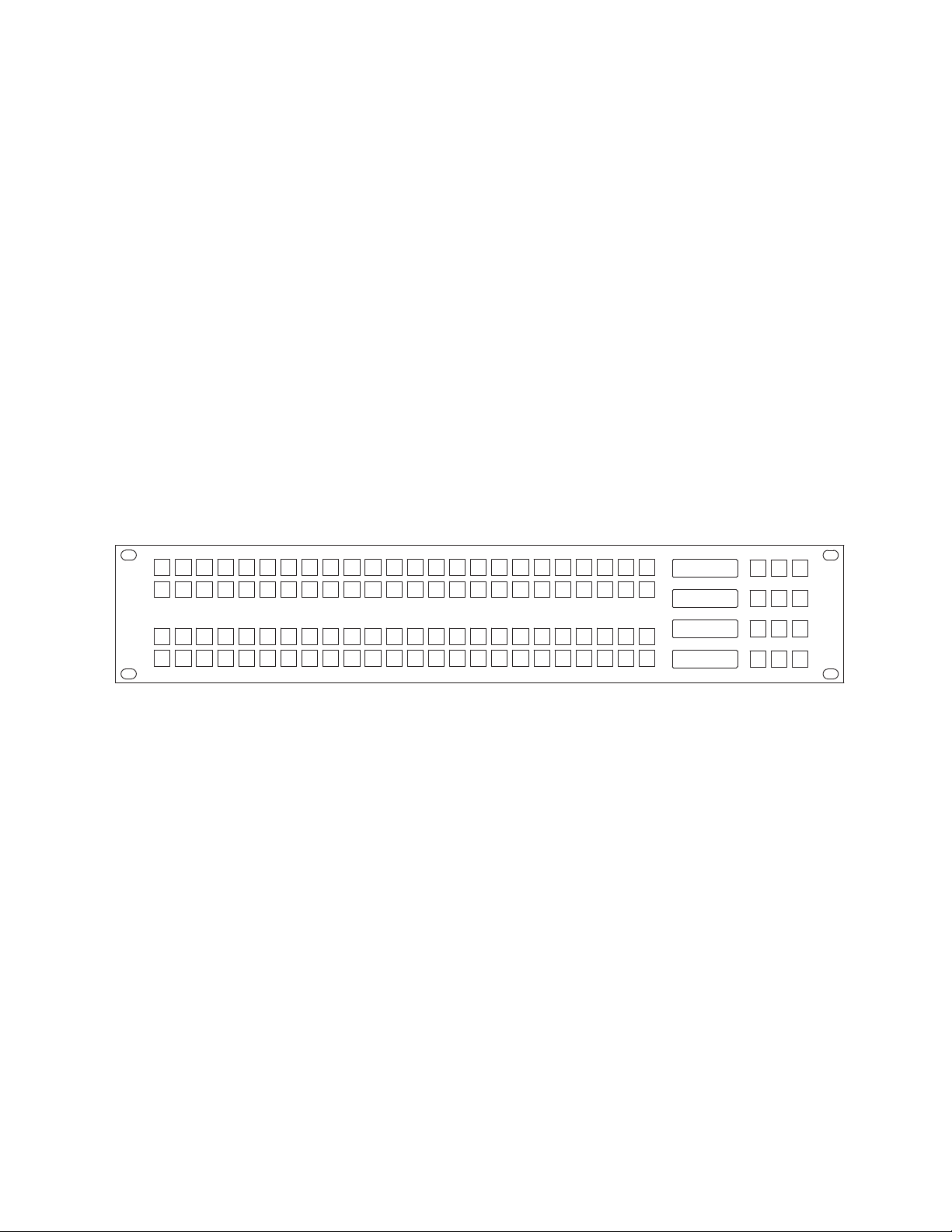
The JEP-100 Jupiter/Encore Control Panel, which was the first example in
the JEP series, is a locally-programmable, eight-character mnemonic, fullmatrix control, multiple level break away panel designed especially for use
in television production vans. (
Figure 1. JEP-100 Control Panel
Figure 1)
Section 1
The current version of the panel uses a 15-pin D female connector on the
rear panel to provide a total of 14 control lines (GPI ports) plus ground.
Each port can be used to trigger a switching event when initiated by a
contact closure on a customer-provided device. In the joystick override
application, a joystick such as found on a camera control unit (CCU) can be
used to select a camera for QC evaluation.
The panel includes a fully-enclosed auto-sensing power supply with an
inrush current rating of 7.9 A. The nominal power requirement is 0.4 A @
240 VAC or 0.65 A @ 120 VAC. There is no power switch (the AC cord must
be disconnected to power down the panel).
The 96 keys on the left side of the panel are initially assigned to inputs using
the control system file server, but some or all can be re-assigned to new
inputs at any time using only the panel itself. The keys can alternatively be
used to control outputs or levels.
Sources, destinations, and levels can also be selected by scrolling up/ down
in the various LED displays.
JEP Series — Installation Manual 23
Page 24

Section 1 — JEP-100 Control Panel
Space has been provided for adhesive strips to be placed on the front
surface for identification of buttons as they are arranged for specific proj
ects.
The JEP-100 control panel is only designed for use with either a Jupiter CM4000, CM-4400 System Controller, or an Encore Control System. The JEP100 panel is not intended for use with Jupiter VM-3000 System Controllers.
Note The CM-4000/4400 must be operating with Jupiter / AccuSwitch version
Note The CM-4000/4400 must be operating with Jupiter / Saturn / AccuSwitch
In Jupiter applications, the JEP-100 can be connected to the CM-4000/4400
System Controller via a 115k Baud serial bus (maximum distance of 2000
feet); or via a Cat 5 Ethernet connection (maximum distance per segment
329 feet). An Ethernet connection is required for software upgrade pur
poses.
-
7.9.1 to support the JEP-100 1.3.0 feature set.
version 7.3.2 to support the JEP-100 1.1.1 feature set (except Salvo. JEP-100
salvo requires Jupiter version 7.4 software).
-
Specifications
Physical Dimensions: 2 RU rack mount: 19 in. Width x 3.5 in. Height x
approx. 4 in. Depth (483 mm W x 89 mm H x 102 mm D)
Weight: 2.25 lb. (1.02 kg.)
Operating voltage: 90 to 260 VAC
Operating current: 0.4 A @ 240 VAC or 0.65 A @ 120 VAC
Inrush current rating: 7.9 A
Power consumption: <100 W
Joystick override: Connector, 15-pin D, female.
The wiring between the rear-panel connector and a customer-supplied
contact closure device: minimum 22 AWG (American Wire Gauge);
maximum length, 30 feet (10 meters).
24 JEP Series — Installation Manual
Page 25

Hardware Installation - Jupiter System
The JEP-100 can be connected to the CM-4000 or CM-4400 System Controller via a 115k Baud serial bus or via a Cat 5 Ethernet connection. It is also
possible to combine these methods by connecting some panels serially and
others through the LAN.
An Ethernet connection is required for upgrading the panel software, for all
panels, even if you use a serial connection to connect to the CM-4000 or
CM-4400 to the panels.
Hardware Installation - Jupiter System
JEP Series — Installation Manual 25
Page 26
Section 1 — JEP-100 Control Panel
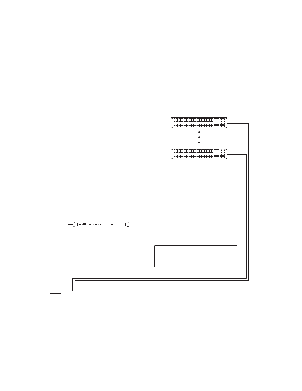
LAN (Cat 5 Ethernet) cable.
Max. recommended length per
segment = 100 meters (329 ft)
CM-4000/4400
System
Controller
100baseT Jupi-
ter LAN
to Jupiter
File Server
IP switch
64 LAN#operated
JEP#100s per CM
maximum
8536_08
LAN Only System
In this arrangement the JEP is operated in Ethernet mode, where the LAN
connection is used both for operation and for software upgrade purposes.
See
Figure 2.
Note The LAN must be capable of 100 Mb operation. Each Ethernet segment (hub
Figure 2. LAN only system connections.
to panel) has a 100 meter limit.
26 JEP Series — Installation Manual
Page 27
Serial System
CM
CM -4000 System Controller
Serial
Ports
100baseT Jupi-
ter LAN
16 JEP
100s per
serial bus maximum
IP switch
to Jupiter
File Server
Serial data cable
LAN (Cat 5 Ethernet) cable.
Max. recommended length per
segment = 100 meters (329 ft)
Temporary LAN connection for
software upgrade.
Serial bus
Serial bus
8536_09
-4400 or
Hardware Installation - Jupiter System
This wiring arrangement assumes that the JEP-100(s) will be operated in
Serial mode, with the LAN typically connected to one panel at a time only
during software upgrades. See
Note The LAN must be capable of 100 Mb operation. Each Ethernet segment (hub
to panel) has a 100 meter limit.
Figure 3. Serial system connections.
Figure 3.
JEP Series — Installation Manual 27
Page 28

Section 1 — JEP-100 Control Panel
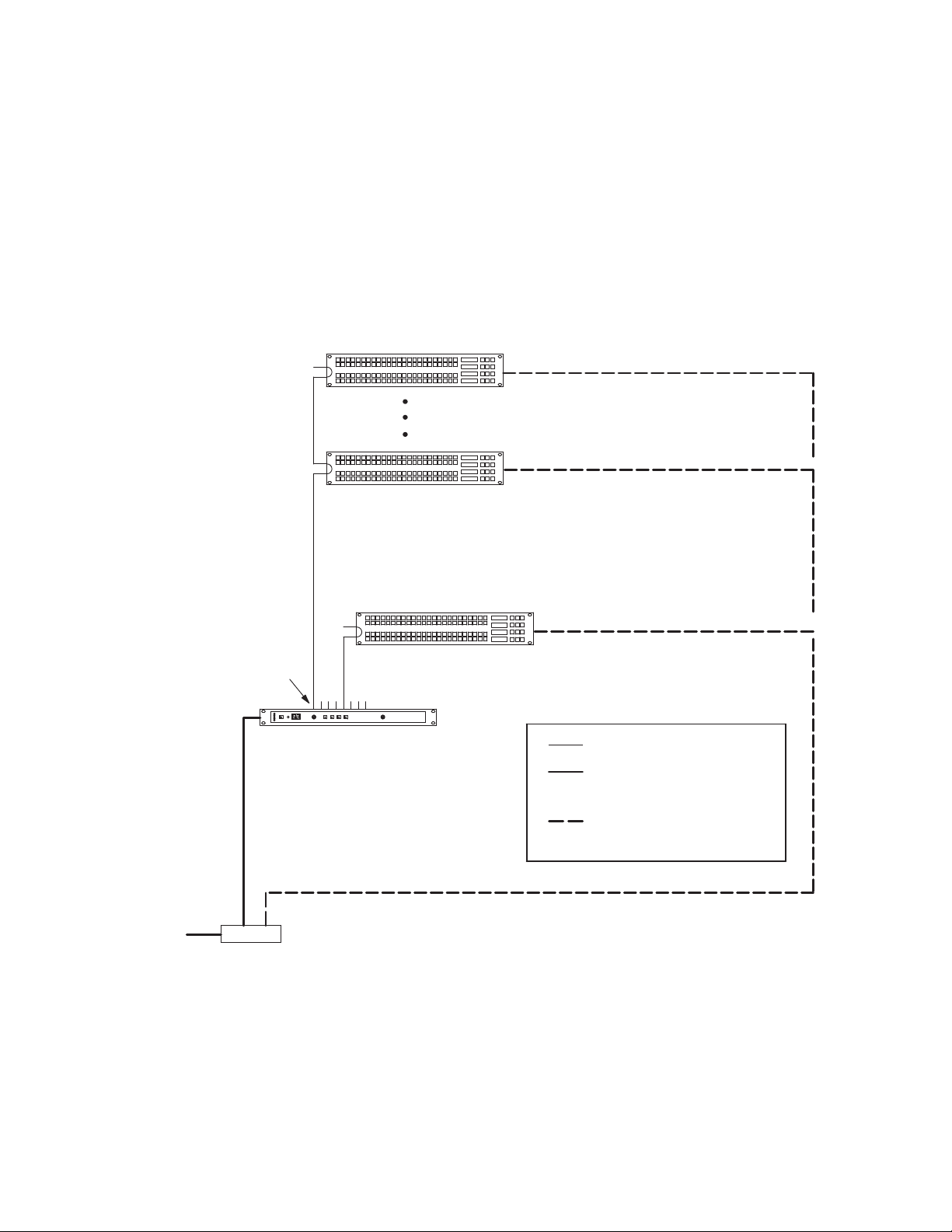
Serial data cable
LAN (Cat 5 Ethernet) cable.
Max. recommended length per
segment = 100 meters (329 ft)
Serial bus
CM -4000 or
CM - 4400 System Controller
Serial
Ports
100baseT Jupi-
ter LAN
A maximum of 16 JEP100s per
serial bus
to Jupiter
File Server
Temporary LAN connection for
software upgrade.
IP switch
A maximum of 64 LAN operated
JEP-100s per C M
LAN + Serial System
In this system, one or more JEP-100s are operated in Serial mode, while
other JEP-100s are operated in LAN mode (
The JEP-100(s) operated in Serial mode will require a LAN connection only
during a software upgrade session. See
Note The LAN must be capable of 100 Mb operation. Each Ethernet segment (hub
Figure 4. LAN + Serial system connections
Figure 4).
Figure 3 on page 27.
to panel) has a 100 meter limit.
Maximum of JEP-100 panels per CM:
• Connected to a Serial Bus - 16.
• Connected to a LAN - 64.
28 JEP Series — Installation Manual
Page 29

Serial Data Cables
1
2
3
7
8
1
2
8
P1
DB9P
(male)
Shield (drain)
Green
Black
White
P2
DB9P
(male)
3
7
Red
Frame ground
CM-4000/4400 System
Controller
(bus controller)
Control panel or
VTR
(tributary)
Receive A (#)
Transmit A (#)
Receive B (+)
Transmit B (+)
Transmit B (+)
Transmit A (#)
Receive B (+)
Receive A (#)
Frame ground
Individually shielded, twisted pairs
Ferrite core
Ferrite core
Green
Black
White
Red
8536_11
The RS-422 cables used to connect CM-4000 or CM-4400 System Controllers
and control panels consist of a 4-conductor (plus ground) cable. Maximum
length per bus, at 115k Baud, is 610 meters (2000 ft.).
The rear panel serial data cable connectors on the CM-4000 or CM-4400 and
control panels are 9-pin D, female. The control panel connectors are
arranged for loop-through wiring. No termination is required. While these
connectors are ESbus compatible, it should be noted that the Grass Valley
serial data cables use only 5 of the 9 pins described in the ESbus specifica
tion.
The following ready-made cables, with installed 9-pin D male connectors,
are available from Grass Valley (VDE cables include ferrite cores):
Table 3. Ready-Made Cables
1meter (3.3 ft.) 8 meters (26.2 ft.)
2 meters (6.6 ft.) 16 meters (52.5 ft.)
4 meters (13.1 ft.) 32 meters (105 ft.)
Hardware Installation - Jupiter System
-
For those who wish to prepare their own cables, the pin-outs are shown in
Figure 5. The cable itself should be Belden 8723 or equivalent.
Details concerning ferrite cores are given in Figure 6 on page 30.
Figure 5. Serial Data Cable Wiring.
JEP Series — Installation Manual 29
Page 30

Section 1 — JEP-100 Control Panel
Type 43 material
0.250 inch (6.35 mm) inside diameter
0.95 inch (24.13 mm) length (or longer)
Type 43 material sources
Fair Rite, part no. 2643480002
Fair Rite Products Corp., P .O. Box J, Commercial
Row, Wallkill, NY 12589, USA; Tel. (914) 895 2055.
Chomerics, part no. 83 10 A636 1000
Chomerics Inc., 77 Dragon Ct., Woburn, MA 01888
USA; Tel. (617) 935 4850.
8536_12
VDE Modifications to Serial Data Cables
User-supplied serial data cables for VDE installations require a ferrite core
over each end of the cable, adjacent to the connector.
Figure 6. Serial data cable VDE modifications.
Joystick Override
This function applies only to the current JEP-100 model, which has a 15-pin
D female connector on the rear panel to provide a total of 14 joystick control
lines plus ground.
30 JEP Series — Installation Manual
Page 31

Internet Protocol Configuration
IP connection and configuration allows Ethernet operation and provides a
download path for software upgrades using the NetConfig application.
The JEP-100, CM-4000 or CM-4400, and file server PC must be on the same
IP network, or else be connected through a network router/gateway.
The following applies to JEP-100 configuration using the panel's built-in
HTTP web page.
Single Network IP Configuration
The following discussion applies when the Jupiter equipment (file server,
CM-4000 or CM-4400, and JEP-100) is in an isolated network environment.
Internet Protocol Configuration
JEP Series — Installation Manual 31
Page 32

Section 1 — JEP-100 Control Panel
CM-4400 or
4000 System Controller
10/100baseT
Jupiter LAN
IP switch
Panel IP
“192.168.253.102”
Panel ID
“02”
Panel IP
“192.168.253.101”
Panel ID
“01”
Panel IP
“192.168.253.164”
Panel ID
“64”
Jupiter
File Server
“192.168.253.1”
IP
“192.168.253.10”
8536_13
LAN Only System
Figure 7 shows an example of a system addressing where the JEP-100s will
be operated entirely in Ethernet mode. Up to 64 JEP-100s can be controlled
per CM-4000 or CM-4400.
Figure 7. LAN only System Addressing (example).
32 JEP Series — Installation Manual
Page 33

Serial System
CM-4400 or
CM-4000 System Controller
Serial
Ports
100baseT Jupi-
ter LAN
IP switch
Serial
buses
Panel IP
“192.168.253.102”
Panel ID
“02”
Panel IP
“192.168.253.101”
Panel ID
“01”
Panel IP
“192.168.253.116”
Panel ID
“16”
Panel IP
“192.168.253.117”
Panel ID
“01”
IP
“192.168.253.10”
Jupiter
File Server
“192.168.253.1”
8536_14
Figure 8 shows an example of a system addressing where the JEP-100s will
be operated in Serial mode (the LAN connections are for software
upgrade). Because there are more than 16 panels, the 17th panel must be
connected to a second CM port. This results in two panels with an ID of
“01.”
This arrangement assumes that the LAN connections will be made to one
panel at a time only for the purpose of software upgrade. In this case, it isn't
necessary to have a different IP address for each panel; however, to prevent
confusion if more than one panel is connected it is recommended that
unique IP addresses are assigned.
Figure 8. Serial System Addressing (example).
Internet Protocol Configuration
JEP Series — Installation Manual 33
Page 34

Section 1 — JEP-100 Control Panel
Serial bus
CM-4000/4400 System Controller
Serial
Ports
100baseT Jupi
ter LAN
IP switch
64 LAN-operated
JEP-100s per CM
maximum
Panel IP
192.168.253.102"
Panel ID
02"
Panel IP
192.168.253.101"
Panel ID
01"
Panel IP
192.168.253.116"
Panel ID
16"
Jupiter
File Server
192.168.253.1"
LAN + Serial System
Figure 9 shows an example of system addressing where one or more JEP-
100s will be operated in Serial mode, while other JEP-100s are operated in
LAN mode.
The JEP-100(s) operated in serial mode will require a LAN connection only
during a software upgrade session.
Figure 9. Example of LAN + serial system addressing
34 JEP Series — Installation Manual
Page 35

Software Installation Process
JEP-100 series hardware panels are shipped with the current software
installed. There is no need to install panel software on newly shipping sys
tems. However, the IP address must be set on each panel so it can operate
on the network. The NetConfig application is used to discover and set IP
addresses of the JEP-100 series panels. Once version 1.3.0 is installed, Net
Config may also used to update JEP-100 series panel software, by transferring panel code from the computer running NetConfig directly to the
panels.
This section will describe the steps needed to Install the latest software on
the PC, Download the new firmware to the panel using the Network
Download Utility and Updating the panel using the Update Manager
application.
Note The Panels MUST be connected to a LAN connection during a software
upgrade session even if the panel is uses a Serial connection.
Software Installation Process
-
-
Installing the Latest Software Version to the PC
Follow these steps to begin installing the JEP-100 software:
1. Insert the supplied software CDROM into the computer’s CD Drive
and follow the prompts.
Note The CD should automatically start the installation process. If not, browse to
the CD, using Window Explorer, and then click the setup.exe icon.
The JEP-100 Welcome screen will then appear. The space requirements
will be gathered (
Figure 10. JEP-100 Installer Welcome Screen
Figure 10).
JEP Series — Installation Manual 35
Page 36

Section 1 — JEP-100 Control Panel
The Next button will be active when the space requirement gathering is
finished (
Figure 11. JEP-100 Installer Welcome Screen
Figure 11).
2. Click the Next> button to begin the installation process. The Setup Type
screen will then appear (
Figure 12. JEP-100 Installer Setup Type Screen
3. Click the Complete radio button.
4. Click the Next> button to begin the installation process.
Figure 12).
5. Follow the instructions on the following installation screens, click the
Next> button as needed (Figure 13).
36 JEP Series — Installation Manual
Page 37

Software Installation Process
Figure 13. Jupiter VSD Installation Screens
6. The Installed Wizard Completed screen will appear when the
installation process is finished (
Figure 14).
Figure 14. Installation Completed Screen
7. Click the Finish button. The Installation application will then close.
JEP Series — Installation Manual 37
Page 38

Section 1 — JEP-100 Control Panel
Updating to the Latest Software Version
Versions 1.2.0 and earlier used the Network Download Utility to update
software. Follow this process for converting the panels to work with Net
Config.
NetConfig is used to update panels for versions after 1.3.0.
The update process will use three applications: the Download Manager
and the Update Manager. You will then use NetConfig.
All of these programs are installed with the JEP-100 panel software installation.
You will need to know the IP address and Device ID of the hardware that
will be associated with the JEP-100. Grass Valley recommends that you
identify and write down the Device IDs and IP Address for the current
panels before you start the update process.
Using the Network Download Utility
-
This step you will download the new firmware to the panel using the
Network Download Utility.
Follow these steps to load the software onto the panels:
1. Start the Network Download Utility application. (Start>All Programs
>Grass Valley>Jep100 >DownloadManager) Any JEP-100 panels with
1.2.0 on the network should be displayed
Leave the RAM Loader and User Program fields with their default settings,
these are the correct files.
38 JEP Series — Installation Manual
Page 39

Figure 15. The Network Download Utility
2. Click Download
1. Click this area
Updating to the Latest Software Version
2. Highlight the line with the 1.2.0 panel in the middle message area.
3. Click Download (Figure 15) the download process will then start. Watch
the messages in the window to know when the download is complete.
The JEP-100 panel will display “Download is Pending.”
Figure 16. The JEP-100 panel will display “Download is Pending”
Destination
JEP-100
Status
Download
Preset
IS
Level
Pending
Using the Update Manager
In this section you will update the panel, with the previously updated firmware, using the Update Manager application. Control Panels should only
be upgraded one at a time using this tool.
071837202_JEP100_display
Note After using the Download manager, the control panel's IP address was
altered; you will be required to reset the control panel's IP address before
proceeding.
JEP Series — Installation Manual 39
Page 40

Section 1 — JEP-100 Control Panel
Double-click the
Displayed Panel
Enter 6 digit Serial # or the last
6 digits of the MAC address
Follow these steps to load the latest software onto the panels:
1. Start the Update Manager application. (Start>All Programs >Grass
Valley>Jep100 >UpdateManager) Any JEP-100 panels on the network
should be displayed.
The program will find the JEP-100 panels
Figure 17. The Update Manager Application
2. Select the panel and then click the Change IP button. The Change IP
Addresses dialog will then appear.
Note The IP Addresses shown in Figure 18 are used for example only. Enter your
Network settings.
Figure 18. The Change IP Addresses Dialog
3. Select the IP Address check box and then enter a free IP address on your
network.
4. Select and enter the information about your network in the field.
5. Click the OK button.
40 JEP Series — Installation Manual
Page 41

Updating to the Latest Software Version
Selecting the Files to Download
1. Double click the first control panel to upgrade.
2. Select the Download tab at the top of the dialog.
The order of the following steps is very important. The backup file
JEP100backup.bin must be added as the first file in the list.
3. Select the Add File button in the left margin and navigate to C:\program
files\grass valley\jupiter control panels\jep100\...then select the
JEP100backup.bin file.
This file is used as a secondary application in the event that the primary
application should ever fail, and allows you a way to re-load the soft
ware using the NetConfig application again in if the primary application fails.
4. Select the Add File button in the left margin again and navigate to
C:\program files\grass valley\jupiter control panels\jep100\... to
select the JEP100.bin primary file.
-
Figure 19. Selecting the Backup and Bin Files
Assigning Primary and Backup Status to the files
1. Highlight the JEP100backup.bin file and then select the Set Backup
button in the left margin to set Backup file.
2. Highlight the JEP100.bin file and then select the Set Primary button in the
left margin to set Primary file (
Figure 20 on page 42).
JEP Series — Installation Manual 41
Page 42

Section 1 — JEP-100 Control Panel
Click the Reset
Device button
Figure 20. Selecting the Backup and Bin Files
3. Select the Search/Select Device tab.
4. Select the Reset Device button.
Figure 21. The Update Manager Application
Using NetConfig to Reset Network and Panel Settings
The control panel's name and network settings were cleared. This section
describes the steps needed to use the NetConfig application to reset the
control panel's name and network settings.
42 JEP Series — Installation Manual
Page 43

Updating to the Latest Software Version
Select the JEP-100
panel
Note This procedure will work if the Default IP address of the control panel is on
the same network as the computer. If the Default IP address is not, then you
will not be able to access the Panel Web page; in this case you will have to
use Netconfig's change IP tool to set the IP, Gateway, Mask, and Server IP
addresses. After changing the IP address, navigate to the Web page and set
the control panels device ID.
Follow these steps to reset the control panel's name and network settings:
1. Select the JEP-100 panel from the Navigation panel on the left side
(
Figure 22). The JEP Panel page will appear on the right frame.
Figure 22. The Update Manager Application
2. Select the Panel Network link. The Panel Network Configuration page
will then appear.
3. Enter a name in the Panel Device name field.
4. Verify and modify the network settings as necessary.
JEP Series — Installation Manual 43
Page 44

Section 1 — JEP-100 Control Panel
Enter a Device
name
Verily or modify
Network settings
Enter a number ID
5. Enter a number ID in the Device Number field (Figure 23 on page 44).
Figure 23. The JEP Panel Network Configuration Page
The Panel upgrade is now complete.
44 JEP Series — Installation Manual
Page 45

Updating the JEP-100 panel Using NetConfig
Updating the JEP-100 panel Using NetConfig
This section describes the steps that are needed to update the JEP-100 using
the NetConfig application.
Follow these steps to update the JEP-100 software:
1. Start NetConfig.
2. Click the Load SW button in the Tool bar row (Figure 24).
Note You only need to click the Load SW button to access the load software page.
However, you can click the IP View button to see the IP addresses on the left
panel (Figure 25).
Figure 24. Tool bar Row of the NetConfig Application
3. Select the panel from the navigation panel on the left hand side.
4. Select the Panels (v1.3.0) in the select devices to Load area.
5. Click the Preferred panel’s check box under the Client column.
6. Select the Re-boot when complete check box.
7. Click the Load button
Figure 25. Updating the JEP-100
JEP Series — Installation Manual 45
Page 46

Section 1 — JEP-100 Control Panel
IP Configuration Procedure
During the following steps, you will need to know the IP address of the
CM-4000 or CM-4400 that will be associated with the JEP-100. Use the
Jupiter File Server JNS Control Center application to determine the IP
address of the CM-4000 or CM-4400 (the Control Center application is
described in the Jupiter CM-4000 or CM-4400 manual).
You will also need to know the normal IP settings of the file server so they
can be restored at the end of this procedure.
1. At the (first) JEP-100, determine the present IP address of the panel by
pressing MENU, then UP/DOWN until the address is displayed in the
Preset and Level windows.
2. If there are other devices on the Jupiter LAN with this same address,
they must be disconnected at this time.
JEP-100 panels are normally shipped with a default IP address of
192.168.253.100.
3. At the file server PC:
a. Use the PC's Network Settings dialog to temporarily set the TCP/IP
address within the same local network as the JEP-100.
For example, if the JEP-100 address is presently 192.168.253.100,
then the PC address should be changed to be compatible with the
192.168.253.x network (such as "192.168.253.1"). The PC's subnet
mask should be set to 255.255.255.0 (class C network). In a simple
network environment, all other TCP/IP network settings are irrele
vant at this point.
b. Reboot the PC to apply the changes.
If preferred, you can use the MS-DOS "ipconfig" command to
verify the settings.
You must have admin privileges to change Internet settings on a
Windows 2000 PC.
c. Start the http browser (e.g. MS Internet Explorer).
The browser Proxy setting must be turned off. To check the Proxy
setting for Internet Explorer, go to Tools > Internet Options > Con
nections > LAN Settings.
d. Enter the JEP-100 IP address in the URL window. This will display
the JEP-100 web page:
-
-
4. The Panel Information fields are system-generated.
5. For the Network Configuration section:
a. Select DHCP - OFF (unless IP addresses are being set automatically
by a Dynamic Host Configuration Protocol server).
46 JEP Series — Installation Manual
Page 47

Updating the JEP-100 panel Using NetConfig
b. IP address - set to a unique value within the same network as the
CM-4000.
For example, if the CM-4000 or CM-4400 address is 192.168.253.10,
then the JEP-100 address should be changed to reside in the
192.168.253.x network (such as "192.168.253.101").
c. Subnet Mask - set to 255.255.255.0.
d. Gateway - not used in a simple network environment.
If the JEP-100 and the CM-4000, or CM-4400, are on separate networks, the gateway connecting them must be specified.
ES Control Panel Configuration:
a. Protocol Type:
For a LAN only system: select "LAN."
For a Serial system: select "Serial" for normal operation of panel.
Select “LAN” only during the software upgrade process.
For a LAN + Serial system: For panels always operated in LAN
mode, select “LAN.” For panels normally operated in Serial mode,
select “Serial” (select “LAN” only during the software upgrade pro
cess).
-
Note that this selection is identical to the “ELAN on” setting
accessed with the front-panel MENU button.
b. Device Number:
LAN only system: enter a number from 1 to 64. This number must
be unique on this LAN (e.g., unique on network 192.168.253.x).
Serial system: enter a number from 1 to 16. This number must be
unique on the CM-4000 or CM-4400 serial bus being used.
LAN + Serial system: for panels always operated in LAN mode,
enter a number from 1 to 64. For panels normally operated in Serial
mode, enter a number from 1 to 16; this number must be unique on
the CM-4000 or CM-4400 serial bus being used.
Note that the Device Number is referred to as the “ID” within the
JEP-100 MENU system and as the “Address” on the Jupiter MPK
Devices table.
c. ES-LAN Host ID Address: enter the IP address of the CM-4000 or
CM-4400 associated with this panel.
d. Secondary Host ID Address: enter the IP address of the redundant
CM-4000 or CM-4400 (if any).
6. Select Submit.
This will apply the settings and reboot the JEP-100.
JEP Series — Installation Manual 47
Page 48

Section 1 — JEP-100 Control Panel
Note Once the JEP-100 reboots the panel may (depending on the address used)
7. Go to the next JEP-100 and repeat steps 1 through 7 above.
8. When finished, restore the file server PC to the original IP settings.
9. Proceed to the panel configuration instructions in the following section.
no longer be visible from the PC. To return to the page, enter the new IP
address in the browser's URL window.
48 JEP Series — Installation Manual
Page 49

Multi-Network IP Configuration
CM-4000 System Controller
Panel IP
192.168.253.101"
IP switch
Jupiter
File Server
Panel ID
01"
IP: 192.168.253.10"
IP:
192.168.253.1"
Panel IP
192.168.253.102"
Panel ID
02"
Remote JEP-100
Gateway
Facility LAN
Jupiter LAN
IP:
192.168.1.1"
Panel IP:
192.168.1.101"
Gateway:
192.168.1.1"
A “remote” JEP-100 can be placed on a network separate from the other
Jupiter devices, such as on a facility LAN. In Figure 11, an IP router serves
as a gateway between two networks.
Figure 26. Example of LAN addressing with remote JEP-100.
Multi-Network IP Configuration
Configuration is similar to that just described, except that the address of the
gateway must be entered on the web page for the remote JEP-100.
JEP Series — Installation Manual 49
Page 50

Section 1 — JEP-100 Control Panel
100baseT Jupi
ter LAN
IP switch
Panel ID
02"
Panel ID
01"
64 JEP-100s per
CM maximum
Panel ID
64"
Jupiter
File Server
CM-4000 System Controller
CM1"
JEP1"
JEP2"
JEP64"
Configuration - Jupiter
Configuration - Jupiter System
The following overview of JEP-100 installation and configuration assumes
that the reader is familiar with the Jupiter Facility Control System. If not,
please refer to the latest Jupiter CM-4000 or CM-4400 Installation and Oper
ating manual.
LAN Only System
In a system that uses LAN only, the JEP is operated in Ethernet mode,
where the LAN connection is used both for operation and for software
upgrade purposes. (
Figure 27. LAN only system naming and addressing
Figure 27)
-
50 JEP Series — Installation Manual
Page 51

MPK Table Entries
JEP1 ES LAN 01
JEP2 ES LAN 02
1
MPK Devices
MPK
Expansion
Pass
Board
CM1
Port Address Input Sets Output Sets Level Set Overide Set Sequence Set
2
CM1 KXYZ INP KXYZ OUT KXYZ LEV
Devices word
In Panel Out Panel
JEP64 ES LAN 64
64
CM1 KXYZ INP KXYZ OUT KXYZ LEV
KXYZ INP
KXYZ OUT
K
KXYZ LEV
Type
Device
8536_03
Although the JEP is not actually an MPK-type panel (it has an on-board
microprocessor and does not use the Message Per Keystroke protocol), the
MPK table is used for configuration purposes. An example is shown in
Figure 28.
Figure 28. MPK Devices table corresponding to system shown in Figure [12]
MPK Devices - This column is used to create a name, up to eight characters
in length, for each JEP-100. This name must be unique system-wide.
Typ e - Select type “ES-LAN” on the pull-down menu. Select either
“CPESXTND” or “CPES-SER” type for the latest features.
Configuration - Jupiter System
JEP Series — Installation Manual 51
Expansion - Not used for JEP-100 (leave unchecked).
Password - The panel may use the password level entry to enable or disable
certain control panel features.
• If the password is blank, the panel will act as normal.
• If any number from 1 to 89 will disable button assignments, and the
“Change ID”, and connection type menu items.
Board - Name of CM-4000 or CM-4400 associated with this JEP-100. The
source of this name is the Network Description table.
Port - Not used for LAN-only installation.
Address - Panel address from 01 to 64. Must be unique for panels associ-
ated with the same CM-4000 or CM-4400.
JEP-100 panels are normally shipped with a panel address of “01.” Modification of this address was discussed on page 47.
This number is referred to as the “Device Number” on the IP configuration
page and “ID” within the JEP-100 MENU system.
Input Set - Name of CP Input Set to be assigned to this panel. The usual
practice is to have one CP Input Set, containing the names of all inputs,
apply to all panels. However, special CP Input Sets could be created which
list only selected inputs; such a set could be used to prevent certain panels
from selecting specific inputs.
The panel now uses the CPEXTN type input set.
Page 52

Section 1 — JEP-100 Control Panel
In Panel - This column is not used for JEP-100 panels.
Out Set - Output Set name. If the entry is an actual CP Output Set, then the
control panel will be able to control all the outputs listed in that Set.
Depending on the con tents of the set, this would allow for full-matrix or
multi-bus control.
The panel now uses the CPEXTN type set. The panel now has the ability to
assign buttons as destinations, Using the output sets button field same as
the S100 panel.
The CP output set will have to be the CPESXTND type to work with the
newer features.
Alternatively, this field can be used to enter the name of a single switcher
output to be controlled. The source of the output name is the Switcher
Output table.
Out Panel - This column is not used for JEP-100 panels.
Level Set - Select the CP Level Set name. Select the CP3800 Level for the
panel to work with the newer features.
Override - Not used for JEP-100 panels.
Sequence - Now used for JEP-100 panels. Select a CP Sequence set name.
A Sequence set is used to execute a list of switches with a single command.
52 JEP Series — Installation Manual
Page 53

Serial System
Serial
Ports
100baseT Jupi
ter LAN
16 JEP-100s per
serial bus maximum
IP switch
Serial
buses
Panel ID
02"
Panel ID
01"
Panel ID
16"
Panel ID
01"
Jupiter
File Server
CM-4000 System Controller
CM1"
JEP1"
JEP2"
JEP16"
JEP17"
Configuration - Jupiter System
In this application the JEP-100 is operated in Serial mode, with the LAN
connection used only for software upgrade purposes.. (Figure 29)
Figure 29. Serial System Naming and Addressing (Example)
Serial Protocol Table Entries
When a JEP-100 is connected to a CM-4000 or CM-4400 serial port (and
operated in Serial mode), the panel must be configured for “ESCP” protocol
using the Serial Protocol table. The Baud rate should be set at 115K.
JEP Series — Installation Manual 53
Page 54

Section 1 — JEP-100 Control Panel
JEP1 ES LAN 01
JEP2 ES LAN 02
1
MPK Devices
MPK
Expansion
Pass
Board
CM1
Port Address Input Sets Output Sets Level Set Overide Set Sequence Set
2
CM1 KXYZ INP KXYZ OUT KXYZ LEV
Devices word
In Panel Out Panel
JEP64 ES LAN 64
64
CM1 KXYZ INP KXYZ OUT KXYZ LEV
KXYZ INP
KXYZ OUT
K
KXYZ LEV
Type
Device
8536_04
MPK Table Entries
Although the JEP-100 is not actually an MPK-type panel (it has an on-board
microprocessor and does not use the Message Per Key stroke protocol), the
MPK table is used for configuration purposes. An example is shown in
Figure 30.
Figure 30. MPK Devices table corresponding to system shown in Figure [16]
MPK Devices - This column is used to create a name, up to eight characters
in length, for each JEP-100. This name must be unique system-wide.
Typ e - Select type “Serial” on the pull-down menu. To use the extended features, you need to configure CPES-SER type.
Expansion - Not used for JEP-100 (leave unchecked).
Password - Passwords can be used to inhibit certain menu items and
button assignments. This functionality is described in
MPK Table Entries on
page 51 of the LAN section.
Board - Name of CM-4000 or CM-4400 connected to this JEP-100. The
source of this name is the Jupiter Network Description table.
Port - Number of CM-4000 or CM-4400 port connected to this JEP-100.
Address - Panel address from 1 to 16. Must be unique for panels sharing the
same CM-4000 or CM-4400 serial port.
JEP-100 panels are normally shipped with a panel address of “01.”
This number is referred to as the “Device Number” on the IP configuration
page and “ID” within the JEP-100 MENU system.
Input Set - Name of CP Input Set to be assigned to this panel. The usual
practice is to have one CP Input Set, containing the names of all inputs,
apply to all panels. However, special CP Input Sets could be created which
list only selected inputs; such a set could be used to prevent certain panels
from selecting specific inputs.
Use CPEXTN to use the latest features.
54 JEP Series — Installation Manual
In Panel - This column is not used for JEP-100 panels.
Out Set - Output Set name.
Page 55

If the entry is an actual CP Output Set, then the control panel will be able
to control all the outputs listed in that Set. Depending on the contents of the
set, this would allow for full-matrix or multi-bus control. Use CPEXTND to
use the latest features.
Alternatively, this field can be used to enter the name of a single switcher
output to be controlled. The source of the output name is the Switcher
Output table is the same as the LAN Only mode.
Out Panel - This column is not used for JEP-100 panels.
Level Set - Select the CP Level Set name.
Override Set - Not used for JEP-100 panels.
Sequence - Same as the LAN Only mode.
Special Entries Needed to Upgrade Serial Panels
In a Serial system, downloading new software to panels normally operated
in Serial mode will require IP settings. These settings are entered using the
web page..
Configuration - Jupiter System
JEP Series — Installation Manual 55
Page 56

Section 1 — JEP-100 Control Panel
Serial bus
Serial
Ports
100baseT Jupi
ter LAN
16 JEP-100s per
serial bus maximum
IP switch
64 LAN-operated
JEP-100s per CM
maximum
Panel ID
02"
Panel ID
01"
Panel ID
64"
Panel ID
01"
ile Server
CM-4000/4400 System Controller
CM1"
JEP1"
JEP2"
JEP64"
JEP65"
_
LAN + Serial System
The example shown in Figure 31 is of a system where one or more JEP-100s
will normally be operated in Serial mode, while other JEP-100s are always
operated in LAN mode.
The JEP-100(s) operated in Serial mode will require a LAN connection only
during a software upgrade session.
Figure 31. Example of LAN + serial system naming and addressing
Serial Protocol Table Entries
When a JEP-100 is connected to a CM-4000 or CM-4400 serial port (and
operated in Serial mode), the panel must be configured for “ESCP” protocol
using the Serial Protocol table. The Baud rate should be set at 115K. Panels
56 JEP Series — Installation Manual
Page 57

normally operated in LAN mode do not require a Serial Protocol table
JEP1
8536_05
ES LAN 01
JEP2 ES LAN 02
1
MPK Devices
MPK
Expansion
Pass
Board
CM1
Port Address Input Sets Output Sets Level Set Overide Set Sequence Set
2
CM1 KXYZ INP KXYZ OUT KXYZ LEV
Devices word
In Panel Out Panel
JEP64 ES LAN 64
64
CM1 KXYZ INP KXYZ OUT KXYZ LEV
JEP65 Serial 011
65
CM1 KXYZ INP KXYZ OUT KXYZ LEV
KXYZ INP
KXYZ OUT
KXYZ LEV
Type
Device
entry.
MPK Table Entries
Although the JEP-100 is not actually an MPK-type panel (it has an on-board
microprocessor and does not use the Message Per Key stroke protocol), the
MPK table is used for configuration purposes. An example is shown in
Figure 32.
Figure 32. MPK table for system shown in Figure [16]
Configuration - Jupiter System
Device Type - For the panels always operated in LAN mode, select type
“ES-LAN” or “CPEXTN” on the pull-down menu. For the panels normally
operated in Serial mode, select type “Serial.”
Expansion - Not used for JEP-100 (leave unchecked).
Password - Passwords can be used to inhibit certain menu items and
button assignments. This functionality is described in
MPK Table Entries on
page 51 of the LAN section.
Board - Name of CM-4000 or CM-4400 connected to this JEP-100. The
source of this name is the Jupiter Network Description table.
Port - For LAN panels: Not used. For serial panels: Number of CM-4000 or
CM-4400 port connected to this JEP-100.
Address - For the panels always operated in LAN mode: enter the panel
address from 1 to 64; must be unique for panels associated with the same
CM-4000. For the panels normally operated in Serial mode: enter the panel
address from 1 to 16; must be unique for panels sharing the same CM-4000
or CM-4400 serial port.
JEP-100 panels are normally shipped with a panel address of “01.”
JEP Series — Installation Manual 57
This number is referred to as the “Device Number” on the IP configuration
page and “ID” within the JEP-100 MENU system.
Input Set - Name of CP Input Set to be assigned to this panel. The usual
practice is to have one CP Input Set, containing the names of all inputs,
apply to all panels. However, special CP Input Sets could be created which
Page 58

Section 1 — JEP-100 Control Panel
list only selected inputs; such a set could be used to prevent certain panels
from selecting specific inputs.
Input Panel - This column is not used for JEP-100 panels.
Out Set - Output Set name.
If the entry is an actual CP Output Set, then the control panel will be able
to control all the outputs listed in that Set. Depending on the con tents of
the set, this would allow for full-matrix or multi-bus control.
Alternatively, this field can be used to enter the name of a single switcher
output to be controlled. The source of the output name is the Switcher
Output table.
Out Panel - This column is not used for JEP-100 panels.
Level Set - Select the CP Level Set name.
Override Set - Not used for JEP-100 panels.
Sequence Set - Not used for JEP-100 panels.
Special Entries Needed to Upgrade Serial Panels
In a LAN + Serial system, downloading to panels normally operated in
Serial mode will require IP settings. These settings are entered using the
web page. See
Internet Protocol Configuration on page 31.
58 JEP Series — Installation Manual
Page 59

All Systems
Control Panel Sets
Configuration - Jupiter System
Switcher inputs and outputs for the JEP-100 are specified by creating a CP
Level Set of type “CP3000,” a CP Input Set of type “Serial,” and a CP
Output Set of type “Serial.” These sets are assigned to each panel using the
MPK Devices table.
JEP-100 panels that are running as type CPESXTND should use
CPESXTND input and output sets. These panels should also be configured
with CP3800 type level sets.
Note With the JEP-100, the CP Level Set does establish the order in which levels
are displayed on the panel; however, this table is not the source of the display
mnemonics used for the various levels (“Video,” “Left,” etc.). The level
names are instead based on the Switcher “Name” (level name) as entered in
the Switcher Description table, with a maximum length of eight characters.
For this reason, systems with JEP-100 panels require that all Switcher Names
in the Switcher Description table be unique (not just unique within a given
switcher). For example, if switcher “Main” has a level Name “Video,” then
switcher “News” could not also have a level name “Video.”
Note The Type “Serial” Input and Output sets used for the JEP-100 must have an
Entry number “0” in the first row, Entry number “1” in the second row, and
so on in sequence.
The CP Input and Output sets are also the source of the eight-character
mnemonics displayed on the panel.
Further, the CP Input set determines which of the 96 button-per-source
buttons is assigned to which source. The upper left-hand but ton of the JEP100 will select the first input listed on the CP Input Set created and selected
for this particular panel, the next button to the right will select the next
listed input, etc. Override sets are not used.
Audio Mode (Special Stereo Switching)
When used to control Venus or Apex audio routers, the JEP-100 can provide
stereo switching modes, which are Normal, Left, Right, Mix, and Reverse.
In this case, the Switcher Description table must define Left and Right
levels in the Audio column.
For more information, refer to the Switcher Description Table of the Jupiter
CM-4000 or CM-4400 manual.
Salvo Switching
The SALVO key can be used to execute a list of pre-built Jupiter sequences,
where a sequence is a switch of one or more sources to one or more destina
tions.
JEP Series — Installation Manual 59
-
Page 60

Section 1 — JEP-100 Control Panel
Compiling
Before the panel can be used, the edited Jupiter set must be compiled and
the appropriate configuration set made active using the Control Center. For
more information, please refer to the “Configurator” section in either the
Jupiter CM-4000 or CM-4400 manual.
60 JEP Series — Installation Manual
Page 61

JEP-100 CP Operation
46
COLORBAR
VTR 001
VTR 002
VIDEO
8536_06
24
Level Salvo Preset
Lock Dest Src
Up
Assign
and
Select
Menu
Down Clean Take
23
4847
7271
9695
22
70
94
Destination
Status
Preset
Level
The steps needed to operate the JEP-100 manual are described in this section.
Figure 33. JEP-100 LEDs and mode select buttons
Section 2
LED Displays
Destination - the output presently controlled by the panel.
Status - the source presently switched to the panel's controlled output.
Preset - shows the new sources as they are being entered, e.g., scrolled
using the UP and DOWN buttons. After TAKE is pressed, the previous
source is shown in the Preset window. This allows "flip-flopping" the
sources, or switching between the current and preset sources by simply
pressing the TAKE button.
Level - used for level breakaway (split) switching and level-by-level
stausing.
JEP Series — Installation Manual 61
Page 62

Section 2 — JEP-100 CP Operation
Show Button Assignment
The 96 keys on the left side of the panel can be assigned to inputs, outputs,
levels, and salvos. To check button assignments, press PRE SET and one of
the "96 keys;" the name of the in/output, level, or salvo assigned to the key
will be displayed in the Preset window. No actual switching takes place
during this procedure.
Destination Selection / Status Check
To select a destination prior to making a switch or to check status:
1. ASSIGN/SELECT button - ON.
2. DEST button - ON.
3. Select a new destination by using the UP and DOWN arrows to scroll
through all destinations.
When using the UP/DOWN buttons, scrolling past the end of the list will
wrap around to the other end.
It is also possible to program one or more buttons to control outputs
directly.
4. When the preferred destination is displayed in the Destination window,
press the
The name of the input currently switched to this destination will be
shown in the Status window.
Note If panel "A" does not have access to a certain input, but that input has been
Note If the panel cannot be changed to the preferred output, it may have been
TAKE button to select it.
selected by panel "B" for the output presently being statused by panel A, then
panel A has no way of reporting the mnemonic of the input. Under these conditions, panel A will show asterisks (****) for status.
limited to certain outputs by the CP Output set used on the MPK De vices
table.
62 JEP Series — Installation Manual
Page 63

Source Selection (All Levels Take)
Destination
Status
Preset
Level
8536_07
Button-per-source keys
Figure 34.
1. The PRESET and LEVEL buttons should be OFF.
2. Select the preferred input:
• Press one of the button-per-source (BPS) keys on the left side of the
panel (which immediately completes the switch), or
• When the SOURCE button is
to find a source in the Preset window. Press the
plete the switch.
The newly switched source will be shown in the Status window.
If a BPS button was used to select the source (or if a BPS button corresponds to the selected source) the button will illuminate. However, the
button will not illuminate if the first level assigned to the panel on the
Level set table has been set to "No" switching. Nor will it illuminate
unless all levels assigned to the button are switched.
BPS button programming
The BPS button assignments are based on the entries to the CP Input table
but these assignments can be changed using the panel itself.
It is also possible to assign these buttons to a destination or to levels.
ON, the UP/DOWN buttons can be used
TAKE button to com-
JEP Series — Installation Manual 63
Page 64

Section 2 — JEP-100 CP Operation
Level Breakaways (Split Switching)
This function allows different sources to be selected for different levels. For
example, switching video without switching audio.
Note Breakaway in v1.1.1 includes a method similar to that used for the Jupiter CP-
There are two breakaway methods available:
• Default mode - level names are scrolled in the Level window and
• Button-per-level mode - levels are assigned to specific buttons and
Default Mode Breakaway
300/330 panels. With this method, levels are selected first; when the source
is selected with a button-per-source (BPS) key, the switch is executed.
toggled on/off before the switch is made.
toggled on/off before the switch is made. A level can be assigned to
one of the 96 keys on the left side of the panel or one of the top six
keys on the right side of the panel.
1. LEVEL button - ON.
2. Select the wanted levels:
a. Use UP/DOWN to step to the first wanted level.
b. Press ASSIGN/SELECT to toggle the level on/off. Dashes in the Level
window mean the level is de-selected.
c. Repeat as needed for remaining levels.
3. Select the preferred input:
–Press one of the button-per-source (BPS) keys on the left side of the
panel (which immediately completes the switch), or
–Toggle the SOURCE button ON, and use the UP/DOWN buttons to find a
source in the Preset window. Press the TAKE button to complete the
switch. Toggling
As long as LEVEL is ON, the panel will remember the breakaway level(s) previously selected and switch accordingly. When LEVEL is OFF, the panel will
revert to All Level switching.
SOURCE to OFF will exit.
Checking Status of Selected Level
Press CLEAR. With the LEVEL button ON, press UP/DOWN to step to the preferred level. The status of the selected level will be shown in the Status
window.
64 JEP Series — Installation Manual
Page 65

Button-per-Level Mode Breakaway
This method assumes that the levels have been assigned to specific buttons.
1. LEVEL - ON.
Note In this mode, when using a subset of the 96 buttons on the left side of the
panel, the LEVEL button must always be ON for the Level but tons to be effective.
2. Toggle on/off the preferred level(s).
3. Select the preferred input:
• Press one of the button-per-source (BPS) keys on the left side of the
panel (which immediately completes the switch), or
• Toggle the
source in the Preset window. Press the
switch. Toggling
As long as LEVEL is ON, the panel will remember the breakaway level(s) previously selected and switch accordingly. When LEVEL is OFF, the panel will
revert to All Level switching.
SOURCE button ON and use the UP/DOWN buttons to find a
SOURCE to OFF will exit.
Checking Status of Selected Level
Press CLEAR. With the LEVEL button ON, press UP/DOWN to step to the preferred
level. The status of the selected level will be shown in the Status window.
TAKE button to complete the
JEP Series — Installation Manual 65
Page 66

Section 2 — JEP-100 CP Operation
1
Input Set JE P
2
1
2
Entry
BARS
TONE
Input
3
3
TC
4
5
4
5
6
6
VT03
7
7
8VT05
VT01
VT02
VT04
96 95 ESS
0
Logical
0718372-02_Input-set
Defining a Source Button
By default, the 96 keys on left side of the panel are assigned to Entry
numbers 0 through 95 listed in the CP Input set table.
Figure 35. Defining a Source Button - Input Set
66 JEP Series — Installation Manual
Button "1" (the first button) is always equivalent to Entry 0, which in this
example maps to BARS. Buttons can also be programmed from the front
panel using the ASSIGN/SELECT key, as follows:
1. Press CLEAR.
This returns the panel to the "home state."
2. (Optional) Check the preferred key position for the new input:
a. PRESET - ON.
b. Press the key you would like to use. Check the Preset window for
the current assignment.
c. Repeat if necessary to find a suitable location.
d. PRESET - OFF.
3. ASSIGN/SELECT - ON
4. SOURCE - ON.
5. Use the UP/DOWN buttons to select the new input.
The name of the new input is shown in the Preset window.
Page 67

6. Press the preferred button.
The input is now assigned to the button.
The top six function buttons on the right side of the panel can also be
used for sources but only when Alternate mode is active.
Note A source button assignment always refers to an Entry number in the CP Input
Set table. If the table is changed such that the Entry number points to a different Logical Input, the source button will now select the new Logical Input.
JEP Series — Installation Manual 67
Page 68

Section 2 — JEP-100 CP Operation
Defining a Destination Button
Any group of the "96 buttons" can be assigned to individual outputs for "XY" style switching where the operator first selects an output button and
then completes the switch by selecting an input button.
1. Press CLEAR.
This returns the panel to the "home state."
2. (Optional) Check the preferred key position for the output:
a. PRESET - ON.
b. Press the key you would like to use. Check the Preset window for
c. Repeat if necessary to find a suitable location.
d. PRESET - OFF.
3. ASSIGN/SELECT - ON
4. DEST - ON.
the current assignment.
5. Use the UP/DOWN buttons to select the new output.
The name of the new output is shown in the Preset window.
6. Press the preferred button.
The output is now assigned to the button.
The top six function buttons on the right side of the panel can also be used
for destinations but only when Alternate mode is active.
Note A destination button assignment always refers to an Entry number in the CP
Output Set table. If the table is changed such that the Entry number points to
a different Logical Output, the destination button will now select the new
Logical Output.
68 JEP Series — Installation Manual
Page 69

Defining a Level Button
Any group of the "96 buttons" can be assigned to individual levels,
allowing the operator to toggle buttons on and off during a split switch.
1. Press CLEAR.
This returns the panel to the "home state."
2. (Optional) Check the preferred key position for the level:
a. PRESET - ON.
b. Press the key you would like to use. Check the Preset window for
the current assignment.
c. Repeat if necessary to find a suitable location.
d. PRESET - OFF.
3. ASSIGN/SELECT - ON
4. LEVEL - ON.
5. Use the UP/DOWN buttons to select the level.
The name of the level is shown in the Level window.
6. Press the preferred button.
The Level is now assigned to the button.
The button will illuminate to show that the level is selected for
switching.
For level breakaway instructions, see Level Breakaways (Split Switching) on
page 64.
The top six function buttons on the right side of the panel can also be used
for levels but only when Alternate mode is active.
Note A level button assignment always refers to a row number in the CP Level Set
table. If the table is changed such that the row number points to a different
level, the level button will now select the new level.
JEP Series — Installation Manual 69
Page 70

Section 2 — JEP-100 CP Operation
Locking or Unlocking an Output
Locking an output prevents that output from being switched by any panel
in the system, including the initiating panel.
To lock an output:
1. Press the LOCK button.
This has the effect of locking only those levels this control panel can
control (as defined on the CP Level set assigned to the panel). The
button will remain on, indicating the output has been locked by this
panel.
If another Jupiter panel selects this output for control, that panel's LOCK
button will light.
To unlock the output:
1. Press the LOCK button again.
The LOCK button lamp will go off.
LOCK
If the output will not unlock, it has been locked by another panel.
For additional lock information - please refer to the Jupiter CM-4000 or
CM-4400 manual.
70 JEP Series — Installation Manual
Page 71

Salvo Switching
1
Sequence Set - SETUP
Sequence
SETUP1
Input
CAM1
Levels
YYYY
2
3
4
SETUP1 CAM2 YYYY
SETUP1 CAM3 YYYY
SETUP2 CAM1 YYYY
Output
MON1
MON2
MON3
MON3
...
...
...
...
Logical Logical
5
6
SETUP2 CAM2 YYYY
SETUP2 CAM3 YYYY
MON2
MON1
...
...
071_8536_02_seq-table
Note The JEP-100 Salvo function requires Jupiter version 7.4 software (or newer)
The SALVO key can be used to execute a list of pre-built Jupiter sequences,
where a sequence is a switch of one or more sources to one or more destina
tions.
Setting Up a Sequence
A Jupiter sequence is built using the Jupiter Sequence Set table, an
example of which is shown
Figure 36. Example of Jupiter Sequence Set table
to be operating in the CM-4000.
-
The sequence set is given an eight-character (max) name and is of type
"3800."
In this example, sequence set "SETUP" contain two sequences: "SET UP1"
and "SETUP2." "SETUP1" will switch Cameras 1 through 3 into Monitors 1
through 3 (a total of three switches) with a single TAKE command.
"SETUP2" will reverse the order of the cameras in the monitors. Each
sequence can include up to 25 events (switches).
There is no specific limit to the number of sequences, but due to memory
restrictions a limit of 16 is recommended (e.g., "SETUP1" through
"SETUP16."
The sequence set must be assigned to the JEP-100 panel on the Jupiter MPK
Devices table.
For additional information regarding Jupiter sequences and assigning
them to control panels, refer to the CM-4000 or CM-4400 manual.
JEP Series — Installation Manual 71
Page 72

Section 2 — JEP-100 CP Operation
Executing a Sequence
After a sequence is created and downloaded, it can be executed as follows:
1. SALVO button - On.
The name of the first sequence (e.g., "SETUP1") will be shown in the
Status window.
2. Use UP/DOWN to scroll to the preferred sequence.
3. Press the TAKE button to execute the sequence.
Assigning a Sequence to a Button
The 96 keys on the left side of the JEP can be assigned to individual
sequences. Pressing the assigned button will then execute the sequence.
1. ASSIGN button - On.
2. SALVO button - On.
The name of the first sequence (e.g., "SETUP1") will be shown in the
Status window.
3. Use UP/DOWN to scroll to the preferred sequence.
4. Press one of the preferred 96 keys on the left side of the panel.
72 JEP Series — Installation Manual
Page 73

Joystick Override
The current version of the JEP uses a 15-pin D female connector on the rear
panel to provide a total of 14 control lines (GPI ports) plus ground. Each
port can be used to trigger a switching event when initiated by a contact
closure on a customer-provided device.
By default, the contacts connected to Pins 1-14 of the GPI connector are
mapped to Entry numbers 1 through 14 in the CP Input set assigned to the
JEP-100. However, a front-panel menu can be used to manually assign a
port to any router input, or to a sequence (salvo).
Note GPI assignments always refer to the Entry number in the CP Input Set table.
If assigned to a router input, the port can be defined as latching or nonlatching:
If the CP Input table is changed such that the Entry number refers to a different Logical Input, the GPI port will now select the new input.
• In latching mode, the JEP-100 will send a switch command for the
source assigned to the triggered control line and not switch away
from that source until a different source (i.e., a different contact) is
selected by the user. For example, if the operator presses and then
releases a joystick push button, the source will remain selected.
• In non-latching mode, the JEP-100 will send a switch command for
the selected source but switch back to the previous source when the
control line returns to a high state (e.g., when the joystick button is
released). This provides a single-button chop or flip-flop style of
operation.
The example in Figure 37 on page 74 shows the joystick override application, where a CCU joystick is used to select a camera for QC evaluation.
When a camera is selected (camera 2 in this example) and the joystick
button is pressed, the CCU provides a contact closure on relay 2. The
closure is sensed by an optocoupler at pin 2 of the JEP-100 GPI connector,
which results in a command being issued to the CM-4000 or CM-4400 to
switch input C2 to the output presently being controlled by the JEP-100.
Wiring between the rear-panel connector and the customer-supplied
contact closure device should be at least 22 AWG (American Wire Gauge)
and no longer than 30 feet (10 meters). A circuit diagram for ports 1-8 is
shown in Figure 22 (circuitry for ports 8-14 is similar).
JEP Series — Installation Manual 73
Page 74

Section 2 — JEP-100 CP Operation
C1
C2
1
2
3
4
5
6
7
8
TAKE
Thomson
Crosspoint
Bus Router
CM 4000/4400 Control System
Crosspoint Bus
CCU
Joysticks
Serial or LAN
connection
QC monitors
Joystick Port
CCU
GPO ports
Video sources
9
10
11
12
13
14
15
*Grass Valley camera connections - Grass Valley CCU (base
station) models LDK-4053 through LDK-4502 include a
rear-panel 9-pin D connector labelled Sign" (Signalling). Pin 1 of
this connector is designated Preview Out External" and
corresponds to the signals marked POE" in this drawing. Pin 9 is
designated Preview Out External Return" and corresponds to the
signals marked POER."
POE
*
POE
*
POER
*
POER
*
Figure 37. JEP-100 Joystick Override Application
74 JEP Series — Installation Manual
Page 75

Figure 38. JEP-100 Internal Circuitry for GPI Ports 1-8 (ports 9-14 are similar)
TO GPI CONNECTOR
5
14
7
15
8
6
12
5
13
9
1
3
7
8
6
4
2
3
4
2
10
11
131-3152-00
9
10
11
12
13
14
15
16
8
7
6
5
4
3
2
1
R1
9
8
7
6
5
4
3
2
16
15
14
13
12
11
10
1
J5
8
6
4
2
7
5
3
1
U2
8
6
4
7
5
3
220
PS2805-4
150-5082-00
307-5165-00
+3.3V
to U3 and U4
to Rabbit
CPU
JEP Series — Installation Manual 75
Page 76

Section 2 — JEP-100 CP Operation
Configuring a JEP-100 GPI Port (Joystick Override Control Line)
1. MENU button - ON.
2. Use UP/DOWN to scroll to "GPI mode."
3. Press the TAKE button.
The Status window will indicate "GPI 1" (highlighted). This refers to pin
1 on the rear panel connector.
Highlighting is used to indicate the window that will be scrolled using
the
The Preset window will indicate the port's present mode.
To exit GPI mode at any time and return to home state without saving
any changes, press
twice.)
4. Use UP/DOWN to display the number of the preferred port from 1 to 14.
5. Press MENU. This will highlight the mode as shown in the Preset
window.
UP/DOWN buttons.
CLEAR. (Sometimes the CLEAR button must be pressed
6. Use UP/DOWN to select the preferred mode for this port: Latch, NoLatch,
Salvo, or GPI off.
7. Press MENU. The number of the GPI port should now be highlighted.
• If Latch or NoLatch was selected, the name of a router input must
now be specified. Press SRC. This will highlight the Level window
and enable the
selected when this port receives a switch command (i.e., is pulled
low).
• If Salvo was selected, a sequence must now be specified. Press
SALVO. This will highlight the Level window and en able the UP/
DOWN
buttons to scroll to the existing sequence that will be executed
when this port receives a start command (i.e., is pulled low).
8. To apply the setting, press the TAKE button.
9. To save the setting, the number of the port ("GPI 1," etc.) must be
highlighted. Press the
UP/DOWN buttons to scroll to the input that will be
TAKE button. The panel will return to home state.
76 JEP Series — Installation Manual
Page 77

Menu Functions
The various menu modes are entered by selecting MENU, then UP/ DOWN to
scroll to the preferred item in the Preset window.
In general, the window describes what will happen if the TAKE button is
pressed. For example, "Alm. on?" means that Alternate mode will be turned
On by pressing the
AlM. - Alternate Mode
Alternate mode may be useful when all 96 buttons to the left of the status
displays have been assigned to inputs, outputs, or levels and the operator
wants to make additional assignments on a temporary basis. Alternate
mode allows the top six buttons in the right-hand button cluster to be used
for this purpose. For example, the buttons could be used for level selection
during breakaway switching.
See Section 5: The Configurator Application in the CM-4400 Jupiter manual
for the steps needed to make these button assignments. Button assign
ments must be made prior to entering Alternate mode:
• Assigning a source
• Assigning a destination
TAKE button.
-
• Assigning a level
Alternate mode operation
1. MENU button - ON.
2. Use UP/DOWN to display "Alm on" (Alternate mode On), meaning that
this is the mode that will be selected if the
3. Press the TAKE button.
This activates the six "temporary level" buttons (the outlined but tons
in Fig. Lighted buttons initially indicate defined levels.
Figure 39. Example of the Six "Temporary Level" Buttons
TAKE button is pressed.
4. Select the new input.
5. Toggle OFF the level(s) you don't want to switch.
JEP Series — Installation Manual 77
Page 78

Section 2 — JEP-100 CP Operation
6. Press the TAKE button to complete the switch on the selected levels.
78 JEP Series — Installation Manual
Page 79

SelAMod. - Select Audio Mode (Special Stereo Switching)
The JEP-100 can provide stereo switching modes, which are Normal, Left,
Right, Mix, and Reverse. These changes are made to individual levels prior
to completing a switch.
Note Audio mode will only appear in the Preset window if a Venus or Apex router
is connected and configured for special stereo switching. In particular, the
Jupiter Switcher Description table must define Left and Right levels in the
Audio column. For more information, refer to either the Jupiter CM-4000 or
CM-4400 manual.
To perform a special stereo switch:
1. SOURCE - ON.
2. Use the UP/DOWN buttons to select the new input.
3. Press MENU.
4. Use UP/DOWN to display "SelAMod?" meaning that this is the mode that
will be selected if the
5. Press the TAKE button.
TAKE button is pressed.
The Preset window will display "Pair 1," referring to the first two audio
levels listed in the Jupiter CP Level Set; e.g., Left and Right.
6. If this is the preferred pair, press the TAKE button. If not, use UP/DOWN to
select the appropriate audio pair, and then press the
The current audio mode for the selected pair will be shown.
A maximum of four audio pairs can be defined.
7. Toggle to the preferred mode:
TAKE button.
JEP Series — Installation Manual 79
Page 80

Left signal on Left channel
Right signal on Right channel
Normal" =
Left" = Left signal on Left channel
Right signal on Right channel
Right signal on Left channel
Right" =
Left + Right signals on Left channel
Left + Right signals on Right channel
Mix" =
Right signal on Left channel
Left signal on Right channel
Reverse" =
Left signal on Right channel
Section 2 — JEP-100 CP Operation
8. Press the TAKE button.
9. The last selected Audio mode will remain in effect until explicitly
changed by the operator.
DspAMod. - Display Audio Mode (Special Stereo Switching)
This mode provides a method of checking the Audio mode that is presently
in effect.
1. Press MENU.
2. Use UP/DOWN to display "DspAMod?" meaning that this is the mode that
will be selected if the
3. Press the TAKE button.
The Preset window will display "Pair 1," r
levels listed in the Jupiter CP Level Set; e.g., Left and Right.
4. If this is the preferred pair, press the TAKE button. If not, use UP/DOWN to
select the appropriate audio pair, and then press the
The current Audio mode for the selected pair will
5. Press CLEAR to exit.
TAKE button is pressed.
eferring to the first two audio
TAKE button.
be shown.
80 JEP Series — Installation Manual
Page 81

Locking or Unlocking an Output
This function allows breakaway operation during which the selected
Levels remain selected after a TAKE. For example, you may want to keep
switching different video test signals to a destination but not switch audio
tone. To turn on sticky mode:
1. MENU - ON.
2. Use UP/DOWN to step to "S.M. on?"
3. Press the TAKE button. Sticky mode is now active.
4. Perform a breakaway switch
The breakaway pattern of this switch will remain in effect after the
TAKE command is executed (and also if
For example, if Sticky mode is on, and the operator makes a video-only
switch, the next switch will also be video only unless specified other
wise. In other words, as long as Sticky mode is on the last-selected
breakaway settings will persist.
To find out which levels are sticky, press the TAKE button and then UP/DOWN.
The Level window will show the levels that will switch. If the Level buttons
have been assigned, the appropriate buttons will illuminate.
CLEAR is selected).
-
To cancel sticky levels, press MENU, and then use UP/DOWN to toggle the
display to "S.M off?" Then press the
M.O. - Multiple Output Mode On/Off
This function allows "gang" switching where the same input is switched to
multiple outputs with a single TAKE command. The following procedure
assumes that destination buttons have been assigned.
To turn on Multiple Output mode:
1. MENU - ON.
2. Use UP/DOWN to step to "M.O. on?"
3. Press the TAKE button. Multiple Output mode is now active.
4. Toggle on/off the outputs that you want to switch.
5. Select the preferred input.
6. Press the TAKE button. The input will be switched to all selected outputs.
The breakaway pattern of subsequent switches will remain in effect
after the TAKE command is executed (and also if CLEAR is selected).
TAKE button.
To cancel multiple output mode press MENU, then use UP/DOWN to toggle
the display to "M.O. off?" Then press the
JEP Series — Installation Manual 81
TAKE button.
Page 82

Section 2 — JEP-100 CP Operation
ELAN - Ethernet Mode On/Off
Ethernet mode enables communication through a LAN cable connection.
The ELAN OFF setting enables communication through a serial connec
tion.
Note This feature is disabled if the password in the MPK Devices table is 1-95.
When a LAN + Serial arrangement is used the panel will normally be operated in the Serial mode; however, during software upgrades the Ethernet
mode must be used.
Note When switching between Serial and LAN modes, multiple startup messages
D.T. - Display Time On/Off
In this mode, the time of day (HH:MM:SS) is displayed in the Level
window. The source of this clock is the CM-4000
synchronized with the CM-4000 or CM-4400 approximately every 10 min
utes.
-
may be seen momentarily.
or CM-4400. The clock is
-
Chg ID - Change Panel ID Mode
The panel ID is used to identify an individual panel on the Jupiter MPK
Devices table if the password entered in the MPK Devices table is set high
enough.
When "Chg Id?" is displayed, press the TAKE button; the Name of the panel
(as created on the Jupiter MPK Devices table) will be displayed in the Level
window. Then use
In Serial mode, the ID can range from 1 to 16; in Ethernet mode the ID can
range from 1 to 64. When the preferred ID is shown, press and hold the "24"
button and press TAKE to apply the change. You should see the panel
restart.
Note The panel ID can also be changed on the IP configuration (web) page, where
it is referred to as the Device Number. The panel ID is called “Address” on the
MPK Devices table.
UP/DOWN to select the preferred ID in the Preset window.
v - Version Number Display
Displays the panel software version. Exit by pressing the TAKE buttons.
Internet Protocol Address Display
Displays the IP address for reference. The address can be changed using the
web page. Exit by pressing the
82 JEP Series — Installation Manual
TAKE or CLEAR buttons.
Page 83

Diag - Diagnostic Mode
CPESEXTND
Type
Provides a test of the LED character set and all button lamps. Exit this mode
by pressing
Note Buttons 65, 73, and 81 may not light while in Diagnostics mode. This is a
TAKE or CLEAR.
diagnostics code problem and does not affect the function of the panel.
C.B. - Change Brightness
Changes brightness of LEDs in display windows.
When "C.B. ?" is displayed, press the TAKE button; then use UP/DOWN to select
the preferred brightness level. Exit this mode by pressing
Output Button Assignment
An Output button’s assignment can be made from the Jupiter configuration. Any Output / Destination buttons assignment can now be defined.
See Section 5: The Configurator Application in the CM-4400 Jupiter manual
for the steps needed to make these assignments.
You will need to use the:
TAKE or CLEAR.
• CPESEXTND type for the Output and Input button.
• CP3800 type for Level and Sequences.
Figure 40. Input and Outputs CP Sets
JEP Series — Installation Manual 83
Page 84

Section 2 — JEP-100 CP Operation
CP3800 Type
Figure 41. Levels and Sequences CP Sets
Password Protection
A password level below 90 then a operator cannot:
• Assign sources destinations, levels, or salvos to buttons.
• Change the Id of the panel
• Change the connection type of the panel.
The menu items “change ID” and “ES Lan on/off” will not be visible to the
user.
A password level that is less than 95:
• The button assignment will be enabled
• The user cannot change the connection type, or the panel ID.
A password level of 95 or greater:
The button assignment is enabled and the operator can change the connection type and the panel ID from the menu of the control panel.
Setting Password Protection
Follow these steps to disable the Configuration and Setup menus on the
Control panel:
1. Open the MPK Devices table.
84 JEP Series — Installation Manual
Page 85

Figure 42. Password settings of the MPLK Table
JEP1 CPESXTND 01
JEP2 CPESXTND 02
1
MPK Devices
MPK
Expansion
Pass
Board
CM1
Port Address Input Sets Output Sets Level Set Overide Set Sequence Set
2
CM1 KXYZINP KXYZOUT KXYZLEV
Devices word
In Panel Out Panel
JEP64 CPESXTND 64
64
CM1 KXYZINP KXYZOUT KXYZLEV
KXYZINP
KXYZOUT
K
KXYZLEV
Type
Device
75
92
2. Enter the preferred setting in the Password Level column (Figure 42):
• Enter a number from 1 to 89 to disable both the Configuration and
Setup menus.
• Enter a number from 90 to 94 to disable only the Setup menu.
• Enter a number 95 and higher to enable both menus.
Note If the Password Level column is left blank, both menus will be accessible.
In the example shown in Figure 42 a password level of 75 and 92 have been
entered.
3. Apply the changes by compiling the appropriate sets and then activate
the sets using the control center.
• For more information about applying changes in Jupiter see the
Jupiter CM-4000 or CM-4400 manuals
Disabling the Configuration and Setup Menus
The Control panels buttons may be disabled. Any button can be configured
to be unassigned for an input or output (Blank Buttons), which may be
used as a separator.
You will need to set the mnemonic for a source or destination to be
“BLANK.” The panel will then disable the button for that source or desti
nation.
Follow these steps to disable the buttons for a Source or Destination on the
Control panel:
1. Open the Switcher Output table.
2. Enter the text, “BLANK” in the Logical Output Name column
3. Open the CP Output table.
4. Enter the text, “BLANK” in the mnemonic column (see Figure 43).
-
JEP Series — Installation Manual 85
Page 86

Section 2 — JEP-100 CP Operation
Enter BLANK
Enter BLANK
Figure 43. BLANK in the Output Switcher and Panel Tables
5. Enter the number of the desired button in the Button Assignment
column.
6. Apply the changes by compiling the appropriate sets and then activate
the sets using the control center.
See the latest CM-4400 manuals for more information about these updates.
86 JEP Series — Installation Manual
Page 87

INDEX
Symbols
**** (as status display) 62
A
AlM. (Alternate mode) 77
Apex 59
Audio mode 79
B
Belden
29
8723
Breakaway 64
C
C.B. (Change Brightness) 83
Chg ID 82
CM-4000 9, 24
Pin outs, serial ports 29
Current (operating) 24
G
GPI ports 73
Grass Valley web site 4, 9
I
Inrush current 23, 24
IP (Menu mode) 82
IP address 35
J
Joystick override 73
Jupiter
50
tables
L
Level
breakaway
64
M
M.O. (Multiple Outputs) 81
D
D.T. (Display Time) 82
Diag (Diagnostics) 83
Dimensions 24
documentation online 4
DspAMod (Display Audio Mode) 80
Mains voltage 23
Menu button 77
MPK
Bus
Max length
29
N
E
ELAN (Ethernet) 82
F
FAQ database 4
Ferrite 30
frequently asked questions 4
JEP Series — Installation Manual 1
NetConfig
overview
35
O
online documentation 4
Page 88

INDEX
P
Pair (audio) 79
Power consumption 24
Power requirements 23
Power supply
auto-sensing
Preset
button
display 61
23
62
R
RS-422
Cable
Connection to system controller
S
Salvo 71
SelAMod (Display Audio Mode) 79
Sequence 71
Serial
Data cable
VDE modifications
software
factory installed
software download from web 4
Specifications 24
Split
switching
Status
display
Stereo switching (Audio mode) 79
Switcher Description table 59, 79
61
35
64
web site Grass Valley 4, 9
web site software download 4
Weight 24
29
30
V
Venus 59
Version (Menu mode) 82
Voltage (mains) 24
W
web site documentation 4
web site FAQ database 4
JEP Series — Installation Manual 2
 Loading...