

Page 1

JEP-100
Jupiter / Encore Control Panel
Installation and Operating Manual
SOFTWARE VERSION 1.2.0
071837201
February 20, 2007
Page 2

Affiliate with the N.V. KEMA in The Netherlands
A
CERTIFICATE
Certificate Number: 510040.001
The Quality System of:
Grass Valley, Inc.
400 Providence Mine Road
Nevada City, CA 95945
United States
15655 SW Greystone Ct.
Beaverton, OR 97006
United States
10 Presidential Way
rd
3
Floor, Suite 300
Woburn, MA 01801
United States
Nederland B.V.
4800 RP BREDA
The Netherlands
Technopole Brest Iroise
CS 73808
29238 Brest Cedex 3
France
7140 Baymeadows Way
Suite 101
Jacksonville, FL 32256
United States
Weiterstadt, Germany
Brunnenweg 9
D-64331 Weiterstadt
Germany
17 rue du Petit Albi-BP 8244
95801 Cergy Pontoise
Cergy, France
Rennes, France
Rue du Clos Courtel
Cesson-Sevigne, Cedex
France
2300 South Decker Lake Blvd.
Salt Lake City, UT 84119
United States
Including its implementation, meets the requirements of the standard:
ISO 9001:2000
Scope:
The design, manufacture and support of video hardware and software products and
related systems.
This Certificate is valid until: June 14, 2009
This Certificate is valid as of: August 30, 2006
Certified for the first time: June 14, 2000
H. Pierre Sallé
President
KEMA-Registered Quality
The method of operation for quality certification is defined in the KEMA General Terms
And Conditions For Quality And Environmental Management Systems Certifications.
Integral publication of this certificate is allowed.
KEMA-Registered Quality, Inc.
4377 County Line Road
Chalfont, PA 18914
Ph: (215)997-4519
Fax: (215)997-3809
CRT 001 073004
ccredited By:
ANAB
Page 3
JEP-100
Jupiter / Encore Control Panel
Installation and Operating Manual
SOFTWARE VERSION 1.2.0
071837201
February 20, 2007
Page 4

Contacting Grass Valley
International
Support Centers
Local Support Centers
(available during normal
business hours)
France
24 x 7
Asia
Australia and New Zealand: +61 1300 721 495
Middle East: +971 4 299 64 40 Near East and Africa: +800 8080 2020 or +33 1 48 25 20 20
Europe
Copyright © Grass Valley, Inc. All rights reserved. All specifications subject to change without notice.
This product may be covered by one or more U.S. and foreign patents.
+800 8080 2020 or +33 1 48 25 20 20
+800 8080 2020 or +33 1 48 25 20 20
Hong Kong, Taiwan, Korea, Macau: +852 2531 3058 Indian Subcontinent:
+91 22 24933476
Southeast Asia/Malaysia: +603 7805 3884 Southeast Asia/Singapore:
+65 6379 1313
China: +861 0660 159 450 Japan: +81 3 5484 6868
Belarus, Russia, Tadzikistan, Ukraine, Uzbekistan: +7 095 2580924 225
Switzerland: +4114878002
S. Europe/Italy-Roma: +39 06 87 20 35 28 -Milan: +390248414658 S. Europe/
Spain: +34 91 512 03 50
Benelux/Belgium: +32 (0) 2 334 90 30 Benelux/Netherlands: +31 (0) 35 62 38 42 1
N. Europe: +45 45 96 88 70
Germany, Austria, Eastern Europe: +49 6150 104 444 UK, Ireland, Israel:
+44 118 923 0499
United States/Canada
24 x 7
Grass Valley Web Site
The www.thomsongrassvalley.com web site offers the following:
Online User Documentation — Current versions of product catalogs, brochures,
data sheets, ordering guides, planning guides, manuals, and release notes
in .pdf format can be downloaded.
2 JEP-100 — Installation and Operating Manual
Page 5

Contents
= New or changed information
Preface. . . . . . . . . . . . . . . . . . . . . . . . . . . . . . . . . . . . . . . . . . . . . . . . . . . . . . . . . . . . . . . . . . . . . 5
About This Manual . . . . . . . . . . . . . . . . . . . . . . . . . . . . . . . . . . . . . . . . . . . . . . . . . . . . . 5
Additional Documentation . . . . . . . . . . . . . . . . . . . . . . . . . . . . . . . . . . . . . . . . . . . . 5
Safety Summary
Safety Terms and Symbols. . . . . . . . . . . . . . . . . . . . . . . . . . . . . . . . . . . . . . . . . . . . . . . 7
Terms in This Manual. . . . . . . . . . . . . . . . . . . . . . . . . . . . . . . . . . . . . . . . . . . . . . . . . 7
Terms on the Product . . . . . . . . . . . . . . . . . . . . . . . . . . . . . . . . . . . . . . . . . . . . . . . . . 7
Symbols on the Product . . . . . . . . . . . . . . . . . . . . . . . . . . . . . . . . . . . . . . . . . . . . . . . 8
Warnings . . . . . . . . . . . . . . . . . . . . . . . . . . . . . . . . . . . . . . . . . . . . . . . . . . . . . . . . . . . . . 8
Cautions . . . . . . . . . . . . . . . . . . . . . . . . . . . . . . . . . . . . . . . . . . . . . . . . . . . . . . . . . . . . . . 9
Regulatory Notices
Certifications and Compliances . . . . . . . . . . . . . . . . . . . . . . . . . . . . . . . . . . . . . . . . . 11
FCC Emission Control . . . . . . . . . . . . . . . . . . . . . . . . . . . . . . . . . . . . . . . . . . . . . . . 11
Canadian EMC Notice of Compliance . . . . . . . . . . . . . . . . . . . . . . . . . . . . . . . . . . 11
EN55022 Class A Warning . . . . . . . . . . . . . . . . . . . . . . . . . . . . . . . . . . . . . . . . . . . . 11
Canadian Certified Power Cords . . . . . . . . . . . . . . . . . . . . . . . . . . . . . . . . . . . . . . 12
Canadian Certified AC Adapter . . . . . . . . . . . . . . . . . . . . . . . . . . . . . . . . . . . . . . . 12
Laser Compliance . . . . . . . . . . . . . . . . . . . . . . . . . . . . . . . . . . . . . . . . . . . . . . . . . . . 12
Laser Safety Requirements . . . . . . . . . . . . . . . . . . . . . . . . . . . . . . . . . . . . . . . . . . 12
Laser Safety. . . . . . . . . . . . . . . . . . . . . . . . . . . . . . . . . . . . . . . . . . . . . . . . . . . . . . . 12
FCC Emission Limits. . . . . . . . . . . . . . . . . . . . . . . . . . . . . . . . . . . . . . . . . . . . . . . 13
Certification . . . . . . . . . . . . . . . . . . . . . . . . . . . . . . . . . . . . . . . . . . . . . . . . . . . . . . . . 13
Section 1 — JEP-100 Control Panel . . . . . . . . . . . . . . . . . . . . . . . . . . . . . . . . . . . . 15
Introduction . . . . . . . . . . . . . . . . . . . . . . . . . . . . . . . . . . . . . . . . . . . . . . . . . . . . . . . . . . 15
Specifications . . . . . . . . . . . . . . . . . . . . . . . . . . . . . . . . . . . . . . . . . . . . . . . . . . . . . . . 16
Hardware Installation - Jupiter System . . . . . . . . . . . . . . . . . . . . . . . . . . . . . . . . . . . 17
LAN Only System . . . . . . . . . . . . . . . . . . . . . . . . . . . . . . . . . . . . . . . . . . . . . . . . . . . 18
Serial System . . . . . . . . . . . . . . . . . . . . . . . . . . . . . . . . . . . . . . . . . . . . . . . . . . . . . . . 19
LAN + Serial System. . . . . . . . . . . . . . . . . . . . . . . . . . . . . . . . . . . . . . . . . . . . . . . . . 20
Serial Data Cables . . . . . . . . . . . . . . . . . . . . . . . . . . . . . . . . . . . . . . . . . . . . . . . . . . . 22
VDE EMI/RFI Modifications to Serial Data Cables . . . . . . . . . . . . . . . . . . . . . 23
Power Surge Protection using JUP-485-SUP Module. . . . . . . . . . . . . . . . . . . . 23
Joystick Override . . . . . . . . . . . . . . . . . . . . . . . . . . . . . . . . . . . . . . . . . . . . . . . . . . . . 23
Internet Protocol Configuration . . . . . . . . . . . . . . . . . . . . . . . . . . . . . . . . . . . . . . . . . 24
Single Network IP Configuration . . . . . . . . . . . . . . . . . . . . . . . . . . . . . . . . . . . . . . 24
LAN Only System . . . . . . . . . . . . . . . . . . . . . . . . . . . . . . . . . . . . . . . . . . . . . . . . . 25
Serial System. . . . . . . . . . . . . . . . . . . . . . . . . . . . . . . . . . . . . . . . . . . . . . . . . . . . . . 26
LAN + Serial System . . . . . . . . . . . . . . . . . . . . . . . . . . . . . . . . . . . . . . . . . . . . . . . 27
IP Configuration Procedure . . . . . . . . . . . . . . . . . . . . . . . . . . . . . . . . . . . . . . . . . 28
Multi-Network IP Configuration . . . . . . . . . . . . . . . . . . . . . . . . . . . . . . . . . . . . . . . . 31
Software Installation. . . . . . . . . . . . . . . . . . . . . . . . . . . . . . . . . . . . . . . . . . . . . . . . . . . 32
Configuration - Jupiter System . . . . . . . . . . . . . . . . . . . . . . . . . . . . . . . . . . . . . . . . . . 33
LAN Only System . . . . . . . . . . . . . . . . . . . . . . . . . . . . . . . . . . . . . . . . . . . . . . . . . . . 34
JEP-100 — Installation and Operating Manual 3
Page 6

— Contents
MPK Table Entries. . . . . . . . . . . . . . . . . . . . . . . . . . . . . . . . . . . . . . . . . . . . . . . . . 35
Serial System . . . . . . . . . . . . . . . . . . . . . . . . . . . . . . . . . . . . . . . . . . . . . . . . . . . . . . . 38
Serial Protocol Table Entries . . . . . . . . . . . . . . . . . . . . . . . . . . . . . . . . . . . . . . . . 39
MPK Table Entries. . . . . . . . . . . . . . . . . . . . . . . . . . . . . . . . . . . . . . . . . . . . . . . . . 39
Special Entries Needed to Upgrade Serial Panels . . . . . . . . . . . . . . . . . . . . . . 40
LAN + Serial System . . . . . . . . . . . . . . . . . . . . . . . . . . . . . . . . . . . . . . . . . . . . . . . . 42
Serial Protocol Table Entries . . . . . . . . . . . . . . . . . . . . . . . . . . . . . . . . . . . . . . . . 43
MPK Table Entries. . . . . . . . . . . . . . . . . . . . . . . . . . . . . . . . . . . . . . . . . . . . . . . . . 43
Special Entries Needed to Upgrade Serial Panels . . . . . . . . . . . . . . . . . . . . . . 44
All Systems. . . . . . . . . . . . . . . . . . . . . . . . . . . . . . . . . . . . . . . . . . . . . . . . . . . . . . . . . 45
Control Panel Sets . . . . . . . . . . . . . . . . . . . . . . . . . . . . . . . . . . . . . . . . . . . . . . . . . 45
Audio Mode (Special Stereo Switching) . . . . . . . . . . . . . . . . . . . . . . . . . . . . . . 45
Salvo Switching . . . . . . . . . . . . . . . . . . . . . . . . . . . . . . . . . . . . . . . . . . . . . . . . . . . 45
Compiling. . . . . . . . . . . . . . . . . . . . . . . . . . . . . . . . . . . . . . . . . . . . . . . . . . . . . . . . 46
Operation. . . . . . . . . . . . . . . . . . . . . . . . . . . . . . . . . . . . . . . . . . . . . . . . . . . . . . . . . . . . 47
LED Displays. . . . . . . . . . . . . . . . . . . . . . . . . . . . . . . . . . . . . . . . . . . . . . . . . . . . . . . 47
Show Button Assignment . . . . . . . . . . . . . . . . . . . . . . . . . . . . . . . . . . . . . . . . . . . . 47
Destination Selection / Status Check . . . . . . . . . . . . . . . . . . . . . . . . . . . . . . . . . . 48
Source Selection (All Levels Take) . . . . . . . . . . . . . . . . . . . . . . . . . . . . . . . . . . . . . 49
BPS button programming . . . . . . . . . . . . . . . . . . . . . . . . . . . . . . . . . . . . . . . . . . 49
Level Breakaways (Split Switching). . . . . . . . . . . . . . . . . . . . . . . . . . . . . . . . . . . . 50
Default Mode Breakaway. . . . . . . . . . . . . . . . . . . . . . . . . . . . . . . . . . . . . . . . . . . 50
Button-per-Level Mode Breakaway . . . . . . . . . . . . . . . . . . . . . . . . . . . . . . . . . . . . 51
Checking Status of Selected Level . . . . . . . . . . . . . . . . . . . . . . . . . . . . . . . . . . . 51
Defining a Source Button. . . . . . . . . . . . . . . . . . . . . . . . . . . . . . . . . . . . . . . . . . . . . 52
Defining a Destination Button . . . . . . . . . . . . . . . . . . . . . . . . . . . . . . . . . . . . . . . . 54
Defining a Level Button . . . . . . . . . . . . . . . . . . . . . . . . . . . . . . . . . . . . . . . . . . . . . . 55
Locking or Unlocking an Output . . . . . . . . . . . . . . . . . . . . . . . . . . . . . . . . . . . . . . 56
Salvo Switching. . . . . . . . . . . . . . . . . . . . . . . . . . . . . . . . . . . . . . . . . . . . . . . . . . . . . 57
Setting Up a Sequence . . . . . . . . . . . . . . . . . . . . . . . . . . . . . . . . . . . . . . . . . . . . . 57
Executing a Sequence . . . . . . . . . . . . . . . . . . . . . . . . . . . . . . . . . . . . . . . . . . . . . . 58
Assigning a Sequence to a Button. . . . . . . . . . . . . . . . . . . . . . . . . . . . . . . . . . . . 58
Joystick Override. . . . . . . . . . . . . . . . . . . . . . . . . . . . . . . . . . . . . . . . . . . . . . . . . . . . 59
Configuring a JEP-100 GPI Port (Joystick Override Control Line) . . . . . . . . . . 62
Menu Functions. . . . . . . . . . . . . . . . . . . . . . . . . . . . . . . . . . . . . . . . . . . . . . . . . . . . . 63
AlM. - Alternate Mode . . . . . . . . . . . . . . . . . . . . . . . . . . . . . . . . . . . . . . . . . . . . . 63
SelAMod. - Select Audio Mode (Special Stereo Switching) . . . . . . . . . . . . . . 64
DspAMod. - Display Audio Mode (Special Stereo Switching) . . . . . . . . . . . 65
S.M. - Sticky Level Mode On/Off. . . . . . . . . . . . . . . . . . . . . . . . . . . . . . . . . . . . 66
M.O. - Multiple Output Mode On/Off . . . . . . . . . . . . . . . . . . . . . . . . . . . . . . . 66
ELAN - Ethernet Mode On/Off . . . . . . . . . . . . . . . . . . . . . . . . . . . . . . . . . . . . . 67
D.T. - Display Time On/Off . . . . . . . . . . . . . . . . . . . . . . . . . . . . . . . . . . . . . . . . 67
Chg ID - Change Panel ID Mode . . . . . . . . . . . . . . . . . . . . . . . . . . . . . . . . . . . . 67
v - Version Number Display . . . . . . . . . . . . . . . . . . . . . . . . . . . . . . . . . . . . . . . . 67
Internet Protocol Address Display . . . . . . . . . . . . . . . . . . . . . . . . . . . . . . . . . . . 67
Diag - Diagnostic Mode . . . . . . . . . . . . . . . . . . . . . . . . . . . . . . . . . . . . . . . . . . . . 68
C.B. - Change Brightness . . . . . . . . . . . . . . . . . . . . . . . . . . . . . . . . . . . . . . . . . . . 68
Glossary . . . . . . . . . . . . . . . . . . . . . . . . . . . . . . . . . . . . . . . . . . . . . . . . . . . . . . . . . . . . . . . . . . 69
Index. . . . . . . . . . . . . . . . . . . . . . . . . . . . . . . . . . . . . . . . . . . . . . . . . . . . . . . . . . . . . . . . . . . . . . 75
4 JEP-100 — Installation and Operating Manual
Page 7

Preface
About This Manual
This manual provides installation and operating information for the JEP100 control panel. This control panels is designed for use with a Jupiter CM4000 System Controller.
Additional Documentation
An electronic copy of this manual is normally provided with the system.
Individual manuals may be ordered by contacting Technical Support. For
contact information, see page 2.
Configuration information for the Jupiter control system itself is contained
in the control system’s documentation set:
Jupiter Control System Release Notes series, 0718275xx.
Jupiter CM-4000 Installation and Operating Manual, 0718261xx.
Jupiter Getting Started Guide, 04-045707-003.
Electronic copies of other routing products documents are available on the
following documentation CDs:
CD 0718274xx. Includes Jupiter CM-4000 manuals.
These documents are also available on our web site. See page 2.
JEP-100 — Installation and Operating Manual 5
Page 8

Preface
6 JEP-100 — Installation and Operating Manual
Page 9

Safety Summary
Read and follow the important safety information below, noting especially
those instructions related to risk of fire, electric shock or injury to persons.
Additional specific warnings not listed here may be found throughout the
manual.
WARNING Any instructions in this manual that require opening the equipment cover
or enclosure are for use by qualified service personnel only. To reduce the
risk of electric shock, do not perform any servicing other than that contained in the operating instructions unless you are qualified to do so.
Safety Terms and Symbols
Terms in This Manual
Safety-related statements may appear in this manual in the following form:
WARNING Warning statements identify conditions or practices that may result in per-
sonal injury or loss of life.
CAUTION Caution statements identify conditions or practices that may result in damage
to equipment or other property, or which may cause equipment crucial to
your business environment to become temporarily non-operational.
Terms on the Product
The following terms may appear on the product:
DANGER — A personal injury hazard is immediately accessible as you read
the marking.
WARNING — A personal injury hazard exists but is not immediately acces-
sible as you read the marking.
CAUTION — A hazard to property, product, and other equipment is present.
JEP-100 — Installation and Operating Manual 7
Page 10
Safety Summary
Symbols on the Product
The following symbols may appear on the product:
Indicates that dangerous high voltage is present within the
equipment enclosure that may be of sufficient magnitude to
constitute a risk of electric shock.
Indicates that user, operator or service technician should refer
to product manual(s) for important operating, maintenance,
or service instructions.
This is a prompt to note fuse rating when replacing fuse(s).
The fuse referenced in the text must be replaced with one
having the ratings indicated.
Identifies a protective grounding terminal which must be connected to earth ground prior to making any other equipment
connections.
Warnings
Identifies an external protective grounding terminal which
may be connected to earth ground as a supplement to an
internal grounding terminal.
Indicates that static sensitive components are present which
may be damaged by electrostatic discharge. Use anti-static
procedures, equipment and surfaces during servicing.
The following warning statements identify conditions or practices that can
result in personal injury or loss of life.
Dangerous voltage or current may be present — Disconnect power and remove
battery (if applicable) before removing protective panels, soldering, or
replacing components.
Do not service alone — Do not internally service this product unless another
person capable of rendering first aid and resuscitation is present.
Remove jewelry — Prior to servicing, remove jewelry such as rings, watches,
and other metallic objects.
Avoid exposed circuitry — Do not touch exposed connections, components or
circuitry when power is present.
8 JEP-100 — Installation and Operating Manual
Page 11

Safety Summary
Use proper power cord — Use only the power cord supplied or specified for
this product.
Ground product — Connect the grounding conductor of the power cord to
earth ground.
Operate only with covers and enclosure panels in place — Do not operate this
product when covers or enclosure panels are removed.
Use correct fuse — Use only the fuse type and rating specified for this
product.
Use only in dry environment — Do not operate in wet or damp conditions.
Use only in non-explosive environment — Do not operate this product in an
explosive atmosphere.
High leakage current may be present — Earth connection of product is essential
before connecting power.
Dual power supplies may be present — Be certain to plug each power supply
cord into a separate branch circuit employing a separate service ground.
Disconnect both power supply cords prior to servicing.
Cautions
Double pole neutral fusing — Disconnect mains power prior to servicing.
Use proper lift points — Do not use door latches to lift or move equipment.
Avoid mechanical hazards — Allow all rotating devices to come to a stop before
servicing.
The following caution statements identify conditions or practices that can
result in damage to equipment or other property
Use correct power source — Do not operate this product from a power source
that applies more than the voltage specified for the product.
Use correct voltage setting — If this product lacks auto-ranging power sup-
plies, before applying power ensure that the each power supply is set to
match the power source.
Provide proper ventilation — To prevent product overheating, provide equip-
ment ventilation in accordance with installation instructions.
Use anti-static procedures — Static sensitive components are present which
may be damaged by electrostatic discharge. Use anti-static procedures,
equipment and surfaces during servicing.
JEP-100 — Installation and Operating Manual 9
Page 12

Safety Summary
Do not operate with suspected equipment failure — If you suspect product damage
or equipment failure, have the equipment inspected by qualified service
personnel.
Ensure mains disconnect — If mains switch is not provided, the power cord(s)
of this equipment provide the means of disconnection. The socket outlet
must be installed near the equipment and must be easily accessible. Verify
that all mains power is disconnected before installing or removing power
supplies and/or options.
Route cable properly — Route power cords and other cables so that they ar not
likely to be damaged. Properly support heavy cable bundles to avoid con-
nector damage.
Use correct power supply cords — Power cords for this equipment, if provided,
meet all North American electrical codes. Operation of this equipment at
voltages exceeding 130 VAC requires power supply cords which comply
with NEMA configurations. International power cords, if provided, have
the approval of the country of use.
Use correct replacement battery — This product may contain batteries. To
reduce the risk of explosion, check polarity and replace only with the same
or equivalent type recommended by manufacturer. Dispose of used bat-
teries according to the manufacturer’s instructions.
Troubleshoot only to board level — Circuit boards in this product are densely
populated with surface mount technology (SMT) components and applica-
tion specific integrated circuits (ASICS). As a result, circuit board repair at
the component level is very difficult in the field, if not impossible. For war-
ranty compliance, do not troubleshoot systems beyond the board level.
10 JEP-100 — Installation and Operating Manual
Page 13

Regulatory Notices
Certifications and Compliances
FCC Emission Control
This equipment has been tested and found to comply with the limits for a
Class A digital device, pursuant to Part 15 of the FCC Rules. These limits
are designed to provide reasonable protection against harmful interference
when the equipment is operated in a commercial environment. This equipment generates, uses, and can radiate radio frequency energy and, if not
installed and used in accordance with the instruction manual, may cause
harmful interference to radio communications. Operation of this equipment in a residential area is likely to cause harmful interference in which
case the user will be required to correct the interference at his own expense.
Changes or modifications not expressly approved by Grass Valley Group
can affect emission compliance and could void the user’s authority to
operate this equipment.
Canadian EMC Notice of Compliance
This digital apparatus does not exceed the Class A limits for radio noise
emissions from digital apparatus set out in the Radio Interference Regulations of the Canadian Department of Communications.
Le présent appareil numérique n’emet pas de bruits radioélectriques
dépassant les limites applicables aux appareils numeriques de la classe A
préscrites dans le Règlement sur le brouillage radioélectrique édicte par le
ministère des Communications du Canada.
EN55022 Class A Warning
In a domestic environment, products that comply with Class A may cause
radio interference in which case the user may be required to take adequate
measures.
JEP-100 — Installation and Operating Manual 11
Page 14

Regulatory Notices
Canadian Certified Power Cords
Canadian Certified AC Adapter
Laser Compliance
Laser Safety Requirements
Canadian approval includes the products and power cords appropriate for
use in the North America power network. All other power cords supplied
are approved for the country of use.
Canadian approval includes the AC adapters appropriate for use in the
North America power network. All other AC adapters supplied are
approved for the country of use.
The device used in this product is a Class 1 certified laser product. Oper-
ating this product outside specifications or altering from its original design
may result in hazardous radiation exposure, and may be considered an act
of modifying or new manufacturing of a laser product under U.S. regula-
tions contained in 21CFR Chapter 1, subchapter J or CENELEC regulations
in HD 482 S1. People performing such an act are required by law to recertify
and reidentify this product in accordance with provisions of 21CFR sub-
chapter J for distribution within the U.S.A., and in accordance with
CENELEC HD 482 S1 for distribution within countries using the IEC 825
standard.
Laser Safety
Laser safety in the United States is regulated by the Center for Devices and
Radiological Health (CDRH). The laser safety regulations are published in
the “Laser Product Performance Standard,” Code of Federal Regulation
(CFR), Title 21, Subchapter J.
The International Electrotechnical Commission (IEC) Standard 825, “Radi-
ation of Laser Products, Equipment Classification, Requirements and
User’s Guide,” governs laser products outside the United States. Europe
and member nations of the European Free Trade Association fall under the
jurisdiction of the Comite European de Normalization Electrotechnique
(CENELEC).
For the CDRH: The radiant power is detected through a 7 mm aperture at
a distance of 200 mm from the source focused through a lens with a focal
length of 100 mm.
For IEC compliance: The radiant power is detected through a 7 mm aper-
ture at a distance of 100 mm from the source focused through a lens with a
focal length of 100 mm.
12 JEP-100 — Installation and Operating Manual
Page 15

FCC Emission Limits
Certification
Category Standard Designed/tested for compliance with:
Safety ANSI/UL 1950-1997 3rd ed.
Regulatory Notices
This device complies with Part 15 of the FCC Rules. Operation is subject to
the following two conditions: (1) This device may not cause harmful interference, and (2) this device must accept any interference received,
including interference that may cause undesirable operation. This device
has been tested and found to comply with FCC Part 15 Class B limits for a
digital device when tested with a representative laser-based fiber optical
system that complies with ANSI X3T11 Fiber Channel Standard.
Professional Video and Audio Equipment
CAN/CSA-C22.2 No. 950-95
EN 60950
JEP-100 — Installation and Operating Manual 13
Page 16

Regulatory Notices
14 JEP-100 — Installation and Operating Manual
Page 17
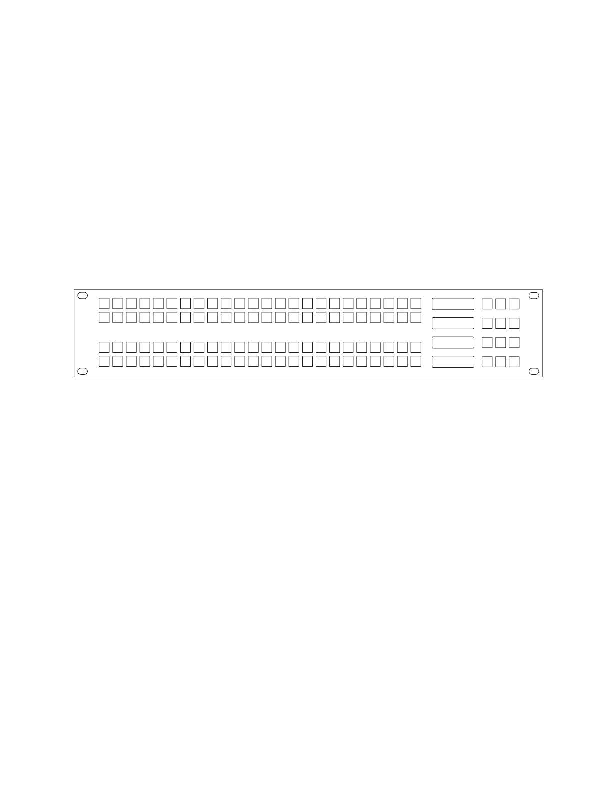
JEP-100 Control Panel
Introduction
Figure 1. JEP-100 C ontrol Panel
Section 1
Destination
Status
Preset
Level
536_02
The JEP-100 Jupiter/Encore Control Panel is a locally-programmable,
eight-character mnemonic, full-matrix control, multiple level break away
panel designed especially for use in television production vans.
The current version of the panel uses a 15-pin D female connector on the
rear panel to provide a total of 14 control lines (GPI ports) plus ground.
Each port can be used to trigger a switching event when initiated by a
contact closure on a customer-provided device. In the joystick override
application, a joystick such as found on a camera control unit (CCU) can be
used to select a camera for QC evaluation.
The panel includes a fully-enclosed auto-sensing power supply with an
inrush current rating of 7.9 A. The nominal power requirement is 0.4 A @
240 VAC or 0.65 A @ 120 VAC. There is no power switch (the AC cord must
be disconnected to power down the panel).
The 96 keys on the left side of the panel are initially assigned to inputs using
the control system file server, but some or all can be re-assigned to new
inputs at any time using only the panel itself. The keys can alternatively be
used to control outputs or levels.
Sources, destinations, and levels can also be selected by scrolling up/ down
in the various LED displays.
JEP-100 — Installation and Operating Manual 15
Page 18

Section 1 — JEP-100 Control Panel
Space has been provided for adhesive strips to be placed on the front
surface for identification of buttons as they are arranged for specific
projects.
The JEP-100 control panel is designed for use with either a Jupiter CM-4000
System Controller or an Encore Control System.
Note At present the JEP-100 can only be used with Jupiter CM-4000 Sys tem Con-
Note The CM-4000 must be operating with Jupiter / Saturn / AccuSwitch version
Note The JEP-100 is not intended for use with Jupiter VM-3000 System Control-
In Jupiter applications, the JEP-100 can be connected to the CM-4000
System Controller via a 115k Baud serial bus (maximum distance of 2000
feet); or via a Cat 5 Ethernet connection (maximum distance per segment
329 feet). An Ethernet connection is required for software upgrade pur-
poses.
trollers.
7.3.2 to support the JEP-100 1.1.1 feature set (except Salvo. JEP-100 salvo
requires Jupiter version 7.4 software).
lers.
Specifications
Physical Dimensions: 2 RU rack mount: 19 in. W x 3.5 in. H x approx. 4 in.
D (483 mm W x 89 mm H x 102 mm D)
Weight: 2.25 lb. (1.02 kg.)
Operating voltage: 90 to 260 VAC
Operating current: 0.4 A @ 240 VAC or 0.65 A @ 120 VAC
Inrush current rating: 7.9 A
Power consumption: <100 W
Joystick override: Connector, 15-pin D, female.
Wiring between rear-panel connector and customer-supplied contact
closure device: minimum 22 AWG (American Wire Gauge); maximum
length, 30 feet (10 meters).
16 JEP-100 — Installation and Operating Manual
Page 19

Hardware Installation - Jupiter System
The JEP-100 can be connected to the CM-4000 System Controller via a 115k
Baud serial bus or via a Cat 5 Ethernet connection. It is also possible to
combine these methods by connecting some panels serially and others
through the LAN.
In all cases, an Ethernet connection is required for software upgrade purposes.
Hardware Installation - Jupiter System
JEP-100 — Installation and Operating Manual 17
Page 20
Section 1 — JEP-100 Control Panel
t
F
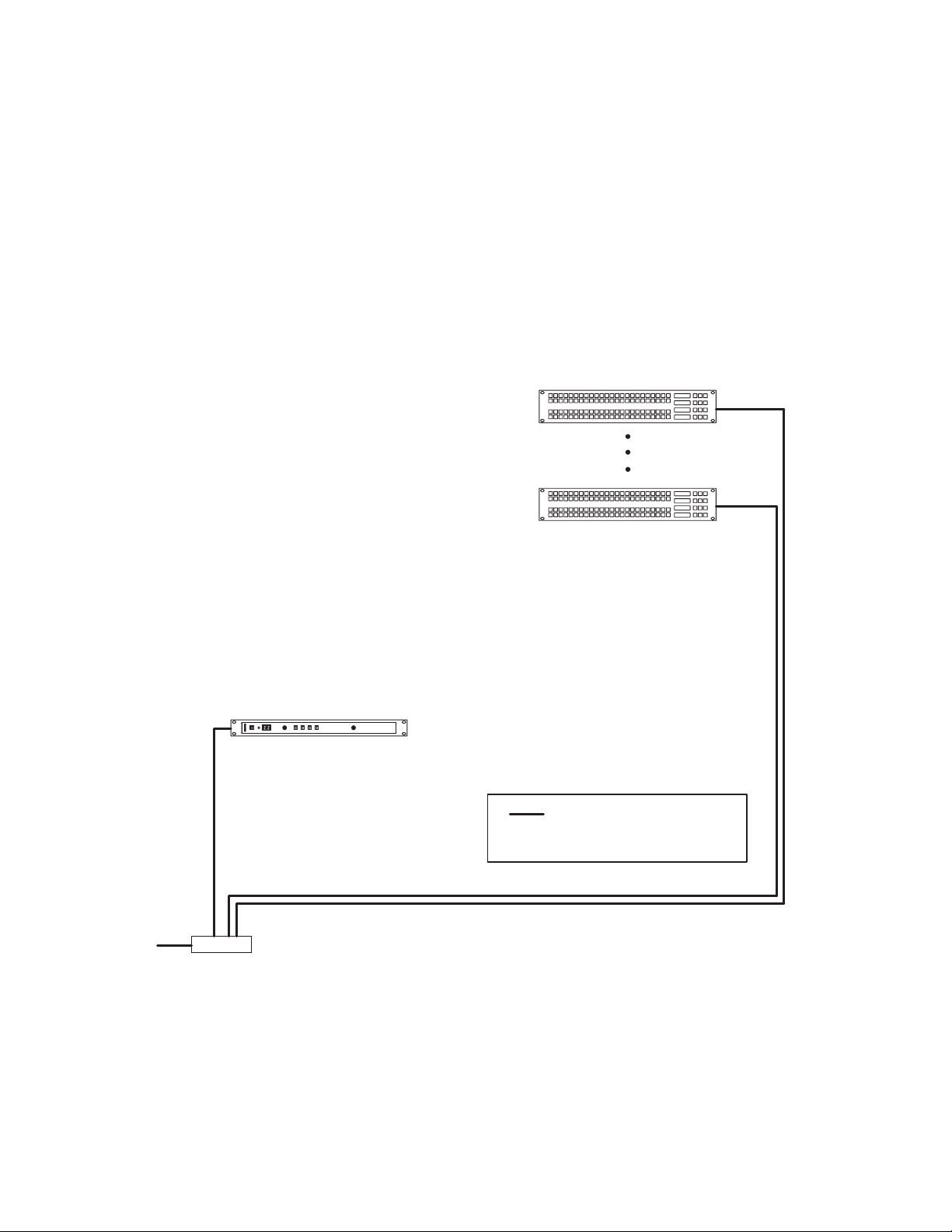
LAN Only System
In this arrangement the JEP is operated in Ethernet mode, where the LAN
connection is used both for operation and for software upgrade purposes.
See Figure 2.
Note The LAN must be capable of 100 Mb operation.
Note Each Ethernet segment (hub to panel) has a 100 meter limit.
Figure 2. LAN only system connections.
64 LAN-operated
JEP-100s per CM
maximum
o Jupiter
ile Server
CM-4000
System
Controller
LAN (Cat 5 Ethernet) cable.
Max. recommended length per
segment = 100 meters (329 ft)
100baseT Jupiter LAN
8536_08
IP switch
18 JEP-100 — Installation and Operating Manual
Page 21
Serial System
t
File Server
8536_09
Serial bus
Hardware Installation - Jupiter System
This wiring arrangement assumes that the JEP-100(s) will be operated in
Serial mode, with the LAN typically connected to one panel at a time only
during software upgrades. See Figure 3.
Note The LAN must be capable of 100 Mb operation.
Note The Ethernet segment (IP switch to panel) has a 100 meter limit.
Figure 3. Serial system connections.
16 JEP-100s per
serial bus maximum
o Jupiter
Serial
Ports
CM-4000 System Controller
100baseT Jupiter LAN
IP switch
Serial bus
Serial data cable (see page 22)
LAN (Cat 5 Ethernet) cable.
Max. recommended length per
seqment = 100 meters (329 ft)
Temporary LAN connection for
software upgrade
JEP-100 — Installation and Operating Manual 19
Page 22

Section 1 — JEP-100 Control Panel
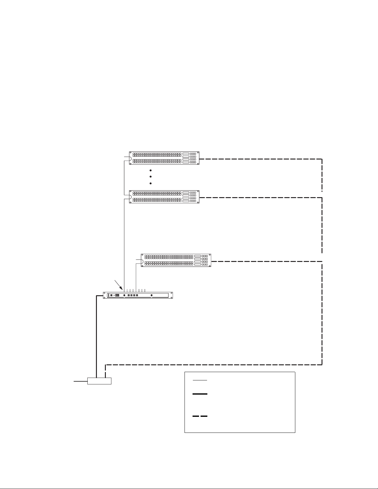
LAN + Serial System
In this system, one or more JEP-100s are operated in Serial mode, while
other JEP-100s are operated in LAN mode. The JEP-100(s) operated in
Serial mode will require a LAN connection only during a software upgrade
session. See Figure 4.
Note The LAN must be capable of 100 Mb operation.
Note Each Ethernet segment (hub to panel) has a 100 meter limit.
20 JEP-100 — Installation and Operating Manual
Page 23
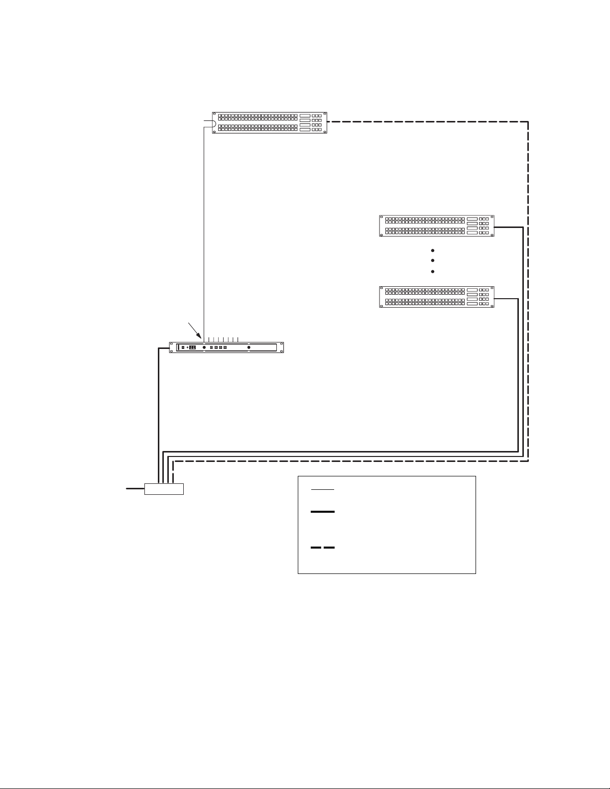
Figure 4. LAN + Serial system connections
t
F
16 JEP-100s per
serial bus maximum
Serial bus
Serial
Ports
Hardware Installation - Jupiter System
64 LAN-operated
JEP-100s per CM
maximum
o Jupiter
ile Server
CM-4000 System Controller
100baseT Jupiter LAN
IP switch
8536_10
Serial data cable (see page 22)
LAN (Cat 5 Ethernet) cable.
Max. recommended length per
seqment = 100 meters (329 ft)
Temporary LAN connection for
software upgrade
JEP-100 — Installation and Operating Manual 21
Page 24
Section 1 — JEP-100 Control Panel
(male)
(male)
F
T
T
+)
#)
)
)
d
Serial Data Cables
The RS-422 cables used to connect CM-4000 System Controllers and control
panels consist of a 4-conductor (plus ground) cable. Maxi mum length per
bus, at 115k Baud, is 610 meters (2000 ft).
The rear panel serial data cable connectors on the CM-4000 and con trol
panels are 9-pin D, female. The control panel connectors are ar ranged for
loop-through wiring. No termination is required. While these connectors
are ESbus compatible, it should be noted that the Thomson serial data
cables use only 5 of the 9 pins described in the ESbus specification.
The following ready-made cables, with installed 9-pin D male connectors,
are available from Grass Valley (VDE cables include ferrite cores):
Tab l e 1 .
1 meter (3.3 ft) 8 meters (26.2 ft)
2 meters (6.6 ft) 16 meters (52.5 ft)
4 meters (13.1 ft) 32 meters (105 ft)
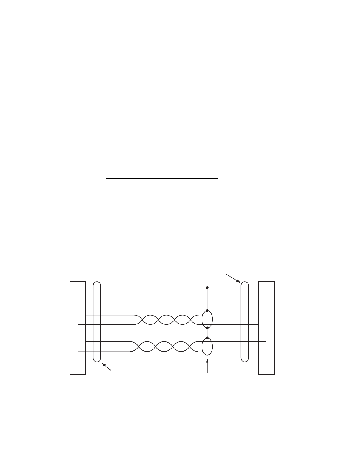
For those who wish to prepare their own cables, the pin-outs are shown in
Figure 5. The cable itself should be Belden 8723 or equiva lent.
Details concerning ferrite cores are given in Figure 6 .
Figure 5. Serial data cable wiring. Reference: "Assembly, BCS-3000 Serial Data Cable," GrassValley
drawing no. 01-041600-TAB.
CM#4000 System
Controller
(bus controller)
rame ground
Receive A (#)
Receive B (+)
ransmit B (+)
ransmit A (#)
1
2
7
3
8
P1
DB9P
Shield (drain)
Green
White
Red
Black
Ferrite core
Individually shielded, twisted pairs
Ferrite core
Green
White
Red
Black
Control panel or
VTR
(tributary)
1
Frame groun
Transmit A (
2
7
Transmit B (
3
Receive B (+
Receive A (#
8
P2
DB9P
8536_11
22 JEP-100 — Installation and Operating Manual
Page 25

VDE EMI/RFI Modifications to Serial Data Cables
0
l
.
8
User-supplied serial data cables for VDE installations require a ferrite core
over each end of the cable, adjacent to the connector.
Figure 6. Serial data cable VDE modifications.
Type 43 material
0.250 inch (6.35 mm) inside diameter
.95 inch (24.13 mm) length (or longer)
Power Surge Protection using JUP-485-SUP Module
Hardware Installation - Jupiter System
Type 43 material sources
Fair Rite, part no. 2643480002
Fair Rite Products Corp., P .O. Box J, Commercia
Row, Wallkill, NY 12589, USA; Tel. (914) 895 2055
Chomerics, part no. 83 10 A636 1000
Chomerics Inc., 77 Dragon Ct., Woburn, MA 0188
USA; Tel. (617) 935 4850.
8536_12
Voltage surges may occur in mobile van environments or other applications
involving long serial cable runs or cases where there is a possibility of a
power spike appearing between the Jupiter CM-4000 System Controller
and a Jupiter control panel. Voltage surges in the 25-volt range have been
known to damage the RS-422/485 driver ICs used in the CM controller. The
JUP-485-SUP module, available as an option, connects to the CM serial port
and uses an internal diode array to limit the voltage on each of the RS-485
conductors to approximately eight volts. For more information, refer to
Field Modification Note 0750790xx or contact Grass Valley Technical Support.
Joystick Override
This function applies only to the current JEP-100 model, which has a 15-pin
D female connector on the rear panel to provide a total of 14 joystick control
lines plus ground. For more information, see page 59.
JEP-100 — Installation and Operating Manual 23
Page 26

Section 1 — JEP-100 Control Panel
Internet Protocol Configuration
IP connection and configuration allows Ethernet operation and pro vides a
downloading path for software upgrades. The JEP-100, CM-4000, and file
server PC must be on the same IP network, or else be connected through a
network router/gateway.
The following applies to JEP-100 configuration using the panel's built-in
HTTP web page.
Single Network IP Configuration
The following discussion applies when the Jupiter equipment (file server,
CM-4000, and JEP-100) is in an isolated network environment.
24 JEP-100 — Installation and Operating Manual
Page 27

LAN Only System
Figure 7 shows an example of a system addressing where the JEP-100s will
be operated entirely in Ethernet mode. Up to 64 JEP-100s can be controlled
per CM-4000.
Figure 7. LAN only system addressing(example).
Internet Protocol Configuration
64 JEP-100s per CM maximum
Jupiter
File Server
“192.168.253.1”
IP
“192.168.253.10”
Panel ID
“64”
Panel ID
“02”
Panel ID
“01”
Panel IP
“192.168.253.164”
Panel IP
“192.168.253.102”
Panel IP
“192.168.253.101”
CM-4000 System Controller
10/100baseT
IP switch
Jupiter LAN
JEP-100 — Installation and Operating Manual 25
8536_13
Page 28

Section 1 — JEP-100 Control Panel
“
8536_14
Serial System
Figure 8 shows an example of a system addressing where the JEP-100s will
be operated in Serial mode (the LAN connections are for software
upgrade). Because there are more than 16 panels, the 17th panel must be
connected to a second CM port. This results in two panels with an ID of
"01."
This arrangement assumes that the LAN connections will be made to one
panel at a time only for the purpose of software upgrade. In this case, it isn't
strictly necessary to have a different IP address for each panel; however, to
prevent confusion if more than one panel is con nected it is recommended
that unique IP addresses are assigned.
Figure 8. Serial system addressing (example).
16 JEP-100s per
serial bus maximum
Panel ID
“16”
Panel ID
“02”
Panel ID
“01”
Serial
buses
Serial
Ports
IP
“192.168.253.10”
Panel ID
“01”
Panel IP
“192.168.253.116”
Panel IP
“192.168.253.102”
Panel IP
“192.168.253.101”
Panel IP
“192.168.253.117”
CM
4000 System Controller
Jupiter
File Server
192.168.253.1”
IP switch
26 JEP-100 — Installation and Operating Manual
100baseT Jupiter LAN
Page 29

LAN + Serial System
Figure 9 shows an example of system addressing where one or more JEP100s will be operated in Serial mode, while other JEP-100s are operated in
LAN mode.
The JEP-100(s) operated in serial mode will require a LAN connection only
during a software upgrade session.
Figure 9. LAN + serial system addressing (example)
Internet Protocol Configuration
16 JEP-100s per serial
bus maximum
Serial
Ports
Panel ID
“01”
Serial bus
Panel IP
“192.168.253.117”
64 LAN operated JEP-100s per CM
Panel ID
“16”
Panel ID
“02”
Panel ID
“01”
Panel IP
“192.168.253.116”
Panel IP
“192.168.253.102”
Panel IP
“192.168.253.101”
CM
Jupiter
File Server
“192.168.253.1”
4000 System Controller
100baseT Jupi-
ter LAN
IP switch
8536_15
JEP-100 — Installation and Operating Manual 27
Page 30

Section 1 — JEP-100 Control Panel
IP Configuration Procedure
During the following steps, you will need to know the IP address of the
CM-4000 that will be associated with the JEP-100. Use the Jupiter File
Server JNS Control Center application to determine the CM-4000 IP
address (the Control Center application is described in the Jupiter CM-4000
manual).
You will also need to know the normal IP settings of the file server so they
can be restored at the end of this procedure.
1. At the (first) JEP-100, determine the present IP address of the panel by
pressing MENU, then UP/DOWN until the address is displayed in the
Preset and Level windows.
2. If there are other devices on the Jupiter LAN with this same address,
they must be disconnected at this time.
JEP-100 panels are normally shipped with a default IP address of
192.168.253.100.
3. At the file server PC:
a. Use the PC's Network Settings dialog to temporarily set the TCP/IP
address within the same local network as the JEP-100.
For example, if the JEP-100 address is presently 192.168.253.100,
then the PC address should be changed to be compatible with the
192.168.253.x network (such as "192.168.253.1"). The PC's sub net
mask should be set to 255.255.255.0 (class C network). In a simple
network environment, all other TCP/IP network settings are irrelevant at this point.
b. Reboot the PC to apply the changes.
If desired, you can use the MS-DOS "ipconfig" command to verify
the settings.
You must have admin privileges to change Internet settings on a
Windows 2000 PC.
c. Start the http browser (e.g. MS Internet Explorer).
The browser Proxy setting must be turned off. To check the Proxy
setting for Internet Explorer, go to Tools > Internet Options > Connections > LAN Settings.
d. Enter the JEP-100 IP address in the URL window. This will display
the JEP-100 web page:
28 JEP-100 — Installation and Operating Manual
Page 31

Figure 10.
Internet Protocol Configuration
8536_16
4. The Panel Information fields are system-generated.
5. For the Network Configuration section:
a. Select DHCP - OFF (unless IP addresses are being set automatically
by a Dynamic Host Configuration Protocol server).
b. IP address - set to a unique value within the same network as the
CM-4000.
For example, if the CM-4000 address is 192.168.253.10, then the JEP100 address should be changed to reside in the 192.168.253.x
network (such as "192.168.253.101").
c. Subnet Mask - set to 255.255.255.0.
JEP-100 — Installation and Operating Manual 29
Page 32

Section 1 — JEP-100 Control Panel
d. Gateway - not used in a simple network environment.
6. ES Control Panel Configuration:
a. Protocol Type:
b. Device Number:
If the JEP-100 and the CM-4000 are on separate networks, the
gateway connecting them must be specified.
For a LAN only system (as shown on page 25): select "LAN."
For a Serial system (page 26): select "Serial" for normal operation of
panel. Select "LAN" only during the software upgrade pro cess.
For a LAN + Serial system (page 27): For panels always operated in
LAN mode, select "LAN." For panels normally operated in Se rial
mode, select "Serial" (select "LAN" only during the software
upgrade process).
Note that this selection is identical to the "ELAN on" setting ac
cessed with the front-panel MENU button.
LAN only system: enter a number from 1 to 64. This number must
be unique on this LAN (e.g., unique on network 192.168.253.x).
Serial system: enter a number from 1 to 16. This number must be
unique on the CM-4000 serial bus being used.
LAN + Serial system: for panels always operated in LAN mode,
enter a number from 1 to 64. For panels normally operated in Se rial
mode, enter a number from 1 to 16; this number must be unique on
the CM-4000 serial bus being used.
Note that the Device Number is referred to as the "ID" within the
JEP-100 MENU system and as the "Address" on the Jupiter MPK
Devices table.
c. ES-LAN Host ID Address: enter the IP address of the CM-4000
associated with this panel.
d. Secondary Host ID Address: enter the IP address of the redundant
CM-4000 (if any).
7. Select Submit.
This will apply the settings and reboot the JEP-100.
Note Once the JEP-100 reboots the panel may (depending on the address used)
no longer be visible from the PC. To return to the page, enter the new IP
address in the browser's URL window.
8. Go to the next JEP-100 and repeat steps 1 through 7 above.
9. When finished, restore the file server PC to the original IP settings.
10. Proceed to the panel configuration instructions in the following section.
30 JEP-100 — Installation and Operating Manual
Page 33

Multi-Network IP Configuration
A "remote" JEP-100 can be placed on a network separate from the other
Jupiter devices, such as on a facility LAN. In Figure 11, an IP router serves
as a gateway between two networks.
Figure 11. LAN addressing with remote JEP-100 (example)
Multi-Network IP Configuration
Panel ID
“02”
Panel ID
“01”
Panel IP
“192.168.253.102”
Panel IP
“192.168.253.101”
CM-4000 System Controller
IP: “192.168.253.10”
Jupiter
File Server
IP switch
IP:
“192.168.253.1”
Jupiter LAN
Remote JEP-100
Facility LAN
Panel IP:
“192.168.1.101”
Gateway:
“192.168.1.1”
Gateway
IP:
“192.168.1.1”
8536_17
Configuration is similar to that just described, except that the address of the
gateway must be entered on the web page for the remote JEP-100.
JEP-100 — Installation and Operating Manual 31
Page 34

Section 1 — JEP-100 Control Panel
Software Installation
JEP-100 panels are shipped with all current software installed.
If the software is being upgraded from a previous version, you must follow
the special upgrade instructions in the appropriate Grass Valley Release
Notes or Field Engineering Bulletin. Failure to do so could result in loss of
user data. For more information, please contact Grass Valley Technical
Support (see page 2).
32 JEP-100 — Installation and Operating Manual
Page 35

Configuration - Jupiter System
The following overview of JEP-100 installation and configuration assumes
that the reader is familiar with the Jupiter Facility Control System. If not,
please refer to the Jupiter CM-4000 Installation and Operating manual,
part. no. 0718261xx.
Configuration - Jupiter System
JEP-100 — Installation and Operating Manual 33
Page 36

Section 1 — JEP-100 Control Panel
F
LAN Only System
In this system, the JEP is operated in Ethernet mode, where the LAN connection is used both for operation and for software upgrade purposes. See
Figure 12.
Figure 12. LAN only system naming and addresssing
“JEP64”
“JEP2”
64 JEP!100s per
CM maximum
Panel ID
“64”
Panel ID
“02”
Jupiter
ile Server
“JEP1”
CM!4000 System Controller
100baseT Jupi-
IP switch
ter LAN
“CM1”
Panel ID
“01”
8536_18
34 JEP-100 — Installation and Operating Manual
Page 37

MPK Table Entries
3
Although the JEP is not actually an MPK-type panel (it has an on-board
microprocessor and does not use the Message Per Keystroke protocol), the
MPK table is used for configuration purposes. An ex ample is shown in
Figure 13.
Figure 13. MPK Devices table corresponding to system shown in Figure 12
MPK Devices
MPK
Devices word
JEP1 ES LAN 01
1
JEP2 ES LAN 02
2
Device
Type
Expansion
Pass
Board
CM1
CM1 KXYZ INP KXYZ OUT KXYZ LEV
Configuration - Jupiter System
Port Address Input Sets Output Sets Level Set Overide Set Sequence Set
KXYZ INP
In Panel Out Panel
KXYZ OUT
KXYZ LEV
K
JEP64 ES LAN 64
64
CM1 KXYZ INP KXYZ OUT KXYZ LEV
MPK Devices - This column is used to create a name, up to eight characters
in length, for each JEP-100. This name must be unique system-wide.
Typ e - Select type "ES-LAN" on the pull-down menu.
Expansion - Not used for JEP-100 (leave unchecked).
Password - Not used for JEP-100.
Board - Name of CM-4000 associated with this JEP-100. The source of this
name is the Network Description table.
Port - Not used for LAN-only installation.
Address - Panel address from 01 to 64. Must be unique for panels associ-
ated with the same CM-4000.
JEP-100 panels are normally shipped with a panel address of "01." Modification of this address was discussed on page 30.
This number is referred to as the "Device Number" on the IP configuration
page and "ID" within the JEP-100 MENU system .
8536_0
Input Set - Name of CP Input Set to be assigned to this panel. The usu al
practice is to have one CP Input Set, containing the names of all in puts,
apply to all panels. However, special CP Input Sets could be created which
list only selected inputs; such a set could be used to prevent certain panels
from selecting specific inputs.
In Panel - This column is not used for JEP-100 panels.
Out Set - Output Set name. If the entry is an actual CP Output Set, then the
control panel will be able to control all the outputs listed in that Set.
Depending on the con tents of the set, this would allow for full-matrix or
multi-bus control.
JEP-100 — Installation and Operating Manual 35
Page 38

Section 1 — JEP-100 Control Panel
Alternatively, this field can be used to enter the name of a single switcher
output to be controlled. The source of the output name is the Switcher
Output table.
Out Panel - This column is not used for JEP-100 panels.
Level Set - Select the CP Level Set name.
Override - Not used for JEP-100 panels.
Sequence - Not used for JEP-100 panels.
36 JEP-100 — Installation and Operating Manual
Page 39

This page intentionally left blank.
Configuration - Jupiter System
JEP-100 — Installation and Operating Manual 37
Page 40

Section 1 — JEP-100 Control Panel
Serial System
In this application the JEP-100 is operated in Serial mode, with the LAN
connection used only for software upgrade purposes. See Figure 14.
Figure 14. Serial system naming and adressing (example)
“JEP16”
“JEP2”
“JEP1”
16 JEP 100s per
serial bus maximum
Panel ID
“16”
Panel ID
“02”
Panel ID
“01”
Jupiter
File Server
Serial
buses
Serial
Ports
CM 4000 System Controller
100baseT Jupi-
ter LAN
IP switch
“CM1”
“JEP17”
Panel ID
“01”
8536_19
38 JEP-100 — Installation and Operating Manual
Page 41

Serial Protocol Table Entries
When a JEP-100 is connected to a CM-4000 serial port (and operated in
Serial mode), the panel must be configured for "ESCP" protocol using the
Serial Protocol table. The Baud rate should be set at 115K.
MPK Table Entries
Although the JEP-100 is not actually an MPK-type panel (it has an on-board
microprocessor and does not use the Message Per Key stroke protocol), the
MPK table is used for configuration purposes. An example is shown in
Figure 15.
Figure 15. MPK Devices table corresponding to system shown in Figure 14
MPK Devices
MPK
Devices word
JEP1 Serial 011
1
JEP2 Serial 02
2
JEP16 Serial 16
16
JEP17 Serial 01
17
Device
Type
Expansion
Pass
Board
CM1
CM1 KXYZ INP KXYZ OUT KXYZ LEV
CM1 KXYZ INP KXYZ OUT KXYZ LEV
CM1 KXYZ INP KXYZ OUT KXYZ LEV
Configuration - Jupiter System
Port Address Input Sets Output Sets Level Set Overide Set Sequence Set
KXYZ INP
1
1
8
In Panel Out Panel
KXYZ OUT
KXYZ LEV
8536_04
MPK Devices - This column is used to create a name, up to eight characters
in length, for each JEP-100. This name must be unique system-wide.
Typ e - Select type "Serial" on the pull-down menu.
Expansion - Not used for JEP-100 (leave unchecked).
Password - Not used for JEP-100.
Board - Name of CM-4000 connected to this JEP-100. The source of this
name is the Jupiter Network Description table.
Port - Number of CM-4000 port connected to this JEP-100.
Address - Pan el a ddre ss fr om 1 to 1 6. M ust be u niq ue f or p ane ls s hari ng th e
same CM-4000 serial port.
JEP-100 panels are normally shipped with a panel address of "01." Modification of this address was discussed on page 30.
This number is referred to as the "Device Number" on the IP configuration
page and "ID" within the JEP-100 MENU system.
Input Set - Name of CP Input Set to be assigned to this panel. The usu al
practice is to have one CP Input Set, containing the names of all in puts,
apply to all panels. However, special CP Input Sets could be created which
list only selected inputs; such a set could be used to prevent certain panels
from selecting specific inputs.
JEP-100 — Installation and Operating Manual 39
Page 42

Section 1 — JEP-100 Control Panel
In Panel - This column is not used for JEP-100 panels.
Out Set - Output Set name.
If the entry is an actual CP Output Set, then the control panel will be able
to control all the outputs listed in that Set. Depending on the con tents of
the set, this would allow for full-matrix or multi-bus control.
Alternatively, this field can be used to enter the name of a single switcher
output to be controlled. The source of the output name is the Switcher
Output table.
Out Panel - This column is not used for JEP-100 panels.
Level Set - Select the CP Level Set name.
Override Set - Not used for JEP-100 panels.
Sequence - Not used for JEP-100 panels.
Special Entries Needed to Upgrade Serial Panels
In a Serial system, downloading new software to panels normally op erated
in Serial mode will require IP settings. These settings are en tered using the
web page. See page 24 .
40 JEP-100 — Installation and Operating Manual
Page 43

This page intentionally left blank.
Configuration - Jupiter System
JEP-100 — Installation and Operating Manual 41
Page 44

Section 1 — JEP-100 Control Panel
F
LAN + Serial System
Figure 16 shows an example of a system where one or more JEP-100s will
normally be operated in Serial mode, while other JEP-100s are always operated in LAN mode.
The JEP-100(s) operated in Serial mode will require a LAN connection only
during a software upgrade session.
Figure 16. LAN + serial system naming and addressing (example)
“JEP65”
16 JEP 100s per
serial bus maximum
Panel ID
“01”
64 LAN operated
JEP 100s per CM
maximum
“JEP64”
Jupiter
ile Server
Serial bus
Serial
Ports
CM 4000 System Controller
100baseT Jupi-
ter LAN
IP switch
“CM1”
“JEP2”
“JEP1”
Panel ID
“64”
Panel ID
“02”
Panel ID
“01”
8536_20
42 JEP-100 — Installation and Operating Manual
Page 45

Serial Protocol Table Entries
8536_05
When a JEP-100 is connected to a CM-4000 serial port (and operated in
Serial mode), the panel must be configured for "ESCP" protocol using the
Serial Protocol table. The Baud rate should be set at 115K. Panels normally
operated in LAN mode do not require a Serial Proto col table entry.
MPK Table Entries
Although the JEP-100 is not actually an MPK-type panel (it has an on-board
microprocessor and does not use the Message Per Key stroke protocol), the
MPK table is used for configuration purposes. An example is shown in
Figure 17.
Figure 17. MPK table for system shown in Figure 16.
Configuration - Jupiter System
MPK Devices
MPK
Devices word
JEP1 ES LAN 01
1
JEP2 ES LAN 02
2
JEP64 ES LAN 64
64
JEP65 Serial 011
65
Device
Type
Expansion
Pass
Board
CM1
CM1 KXYZ INP KXYZ OUT KXYZ LEV
CM1 KXYZ INP KXYZ OUT KXYZ LEV
CM1 KXYZ INP KXYZ OUT KXYZ LEV
Device Type - For the panels always operated in LAN mode, select type
"ES-LAN" on the pull-down menu. For the panels normally operated in
Serial mode, select type "Serial."
Expansion - Not used for JEP-100 (leave unchecked).
Password - Not used for JEP-100.
Board - Name of CM-4000 connected to this JEP-100. The source of this
name is the Jupiter Network Description table.
Port - For LAN panels: Not used. For serial panels: Number of CM-4000
port connected to this JEP-100.
Port Address Input Sets Output Sets Level Set Overide Set Sequence Set
KXYZ INP
In Panel Out Panel
KXYZ OUT
KXYZ LEV
Address - For the panels always operated in LAN mode: enter the panel
address from 1 to 64; must be unique for panels associated with the same
CM-4000. For the panels normally operated in Serial mode: enter the panel
address from 1 to 16; must be unique for panels shar ing the same CM-4000
serial port.
JEP-100 panels are normally shipped with a panel address of "01." Modification of this address was discussed on page 30 .
This number is referred to as the "Device Number" on the IP configuration
page and "ID" within the JEP-100 MENU system.
JEP-100 — Installation and Operating Manual 43
Page 46

Section 1 — JEP-100 Control Panel
Input Set - Name of CP Input Set to be assigned to this panel. The usual
practice is to have one CP Input Set, containing the names of all in puts,
apply to all panels. However, special CP Input Sets could be created which
list only selected inputs; such a set could be used to prevent certain panels
from selecting specific inputs.
Input Panel - This column is not used for JEP-100 panels.
Output Set - Output Set name.
If the entry is an actual CP Output Set, then the control panel will be able
to control all the outputs listed in that Set. Depending on the con tents of
the set, this would allow for full-matrix or multi-bus control.
Alternatively, this field can be used to enter the name of a single switcher
output to be controlled. The source of the output name is the Switcher
Output table.
Out Panel - This column is not used for JEP-100 panels.
Level Set - Select the CP Level Set name.
Override Set - Not used for JEP-100 panels.
Sequence Set - Not used for JEP-100 panels.
Special Entries Needed to Upgrade Serial Panels
In a LAN + Serial system, downloading to panels normally operated in
Serial mode will require IP settings. These settings are entered using the
web page. See page 24.
44 JEP-100 — Installation and Operating Manual
Page 47

All Systems
Control Panel Sets
Configuration - Jupiter System
Switcher inputs and outputs for the JEP-100 are specified by creating a CP
Level Set of type "CP3000," a CP Input Set of type "Serial," and a CP Output
Set of type "Serial." These sets are assigned to each panel using the MPK
Devices table.
Note With the JEP-100, the CP Level Set does establish the order in which levels
are displayed on the panel; however, this table is not the source of the display
mnemonics used for the various levels ("Video," "Left," etc.). The level names
are instead based on the Switcher "Name" (i.e., level name) as entered in the
Switcher Description table, with a maximum length of eight characters. For
this reason, systems with JEP-100 panels require that all Switcher Names in
the Switcher Description table be unique (not just unique within a given
switcher). For example, if switcher "Main" has a level Name "Video," then
switcher "News" could not also have a level name "Video."
Note The Type "Serial" Input and Output sets used for the JEP-100 must have an
Entry number "0" in the first row, Entry number "1" in the second row, and so
on in sequence.
The CP Input and Output sets are also the source of the eight-charac ter
mnemonics displayed on the panel.
Further, the CP Input set determines which of the 96 button-per-source
buttons is assigned to which source. The upper left-hand but ton of the JEP100 will select the first input listed on the CP Input Set created and selected
for this particular panel, the next button to the right will select the next
listed input, etc. Override sets are not used.
Audio Mode (Special Stereo Switching)
When used to control Venus or Apex audio routers, the JEP-100 can provide
stereo switching modes, which are Normal, Left, Right, Mix, and Reverse.
In this case, the Switcher Description table must define Left and Right
levels in the Audio column. For more information, re fer to the Switcher
Description Table in Section 5 of the Jupiter CM-4000 manual.
Audio mode operating instructions are detailed on page 64.
Salvo Switching
The SALVO key can be used to execute a list of pre-built Jupiter se quences,
where a sequence is a switch of one or more sources to one or more destinations. For more information, see page 57.
JEP-100 — Installation and Operating Manual 45
Page 48

Section 1 — JEP-100 Control Panel
Compiling
Before the panel can be used, the edited Jupiter set must be compiled and
the appropriate configuration set made active using the Control Center. For
more information, please refer to Section 5, "Configurator" in the Jupiter
CM-4000 manual.
46 JEP-100 — Installation and Operating Manual
Page 49

Operation
8536_06
Figure 18. JEP-100 LEDs and mode select buttons
Destination
24
23
22
46
4847
VTR 001
Status
COLORBAR
Preset
VTR 002
70
94
7271
9695
Level
VIDEO
Assign
and
Select
Menu
Level Salvo Preset
Lock Dest Src
Up
Down Clean Take
Operation
LED Displays
Destination - the output presently controlled by the panel.
Status - the source presently switched to the panel's controlled out put.
Preset - shows the new sources as they being entered, e.g., scrolled using
the UP and DOWN buttons. After TAKE is pressed, the previous source is
shown in the Preset window. This allows "flip-flopping" the sources, or
switching between the current and preset sources by sim ply pressing the
TAKE b utton.
Level - used for level breakaway (split) switching and level-by-level statusing.
Show Button Assignment
The 96 keys on the left side of the panel can be assigned to inputs, outputs,
levels, and salvos. To check button assignments, press PRE SET and one of
the "96 keys;" the name of the in/output, level, or sal vo assigned to the key
will be displayed in the Preset window. No ac tual switching takes place
during this procedure.
JEP-100 — Installation and Operating Manual 47
Page 50

Section 1 — JEP-100 Control Panel
Destination Selection / Status Check
To select a destination prior to making a switch or to check status:
1. ASSIGN/SELECT button - ON.
2. DEST button - ON.
3. Select a new destination by using the UP and DOWN arrows to scroll
through all destinations.
When using the UP/DOWN buttons, scrolling past the end of the list
will wrap around to the other end.
It is also possible to program one or more buttons to control outputs
directly. See page 52.
4. When the desired destination is displayed in the Destination window,
press the TAKE button to select it.
The name of the input currently switched to this destination will be
shown in the Status window.
Note If panel "A" does not have access to a certain input, but that input has been
selected by panel "B" for the output presently being statused by panel A, then
panel A has no way of reporting the mnemonic of the input. Under these conditions, panel A will show asterisks (****) for status.
Note If the panel cannot be changed to the desired output, it may have been limited
to certain outputs by the CP Output set used on the MPK Devices table. See
Output Set - Output Set name. on page 44.
48 JEP-100 — Installation and Operating Manual
Page 51

Source Selection (All Levels Take)
Figure 19.
Button-per-source keys
1. The PRESET and LEVEL buttons should be OFF.
2. Select the desired input:
–Press one of the button-per-source (BPS) keys on the left side of the
panel (which immediately completes the switch), or
Operation
Destination
Status
Preset
Level
8536_07
–When the SOURCE button is ON, the UP/DOWN buttons can be
used to find a source in the Preset window. Press TAKE to complete
the switch.
The newly switched source will be shown in the Status window.
If a BPS button was used to select the source (or if an BPS button cor
responds to the selected source) the button will illuminate. However,
the button will not illuminate if the first level assigned to the panel on
the Level set table has been set to "No" switching. Nor will it illuminate
unless all levels assigned to the button are switched.
BPS button programming
The BPS button assignments are based on the entries to the CP Input table
(see page 45), but these assignments can be changed using the panel itself
(see page 52).
It is also possible to assign these buttons to a destination (see page 54) or to
levels (see page 55).
JEP-100 — Installation and Operating Manual 49
Page 52

Section 1 — JEP-100 Control Panel
Level Breakaways (Split Switching)
This function allows different sources to be selected for different levels. For
example, switching video without switching audio.
Note Breakaway in v1.1.1 and later includes a method similar to that used for the
There are two breakaway methods available:
• Default mode - level names are scrolled in the Level window and
• Button-per-level mode - levels are assigned to specific buttons and
Default Mode Breakaway
Jupiter CP-300/330 panels. With this method, levels are selected first; when
the source is selected with a button-per-source (BPS) key, the switch is executed.
toggled on/off before the switch is made.
toggled on/off before the switch is made. A level can be assigned to
to one of the 96 keys on the left side of the panel or one of the top
six keys on the right side of the panel.
1. LEVEL button - ON.
2. Select the wanted levels:
a. Use UP/DOWN to step to the first wanted level.
b. Press ASSIGN/SELECT to toggle the level on/off. Dashes in the
Level window mean the level is de-selected.
c. Repeat as needed for remaining levels.
3. Select the desired input:
–Press one of the button-per-source (BPS) keys on the left side of the
panel (which immediately completes the switch), or
–Toggle the SOURCE button ON, and use the UP/DOWN buttons to
find a source in the Preset window. Press TAKE to complete the
switch. Toggling SOURCE to OFF will exit.
As long as LEVEL is ON, the panel will remember the breakaway level(s)
previously selected and switch accordingly. When LEVEL is OFF, the panel
will revert to All Level switching.
Checking Status of Selected Level
Press CLEAR. With the LEVEL button ON, press UP/DOWN to step to the
desired level. The status of the selected level with be shown in the Status
window.
50 JEP-100 — Installation and Operating Manual
Page 53

Button-per-Level Mode Breakaway
This method assumes that the levels have been assigned to specific buttons;
if not see "Defining a Level Button" on page 55 or "Alternate Mode" on
page 63.)
1. LEVEL - ON.
Note In this mode, when using a subset of the 96 buttons on the left side of the
panel, the LEVEL button must always be ON for the Level but tons to be effec-
tive.
2. Toggle on/off the desired level(s).
3. Select the desired input:
–Press one of the button-per-source (BPS) keys on the left side of the
panel (which immediately completes the switch), or
–Toggle the SOURCE button ON and use the UP/DOWN buttons to
find a source in the Preset window. Press TAKE to complete the
switch. Toggling SOURCE to OFF will exit.
Operation
As long as LEVEL is ON, the panel will remember the breakaway level(s)
previously selected and switch accordingly. When LEVEL is OFF, the panel
will revert to All Level switching.
Checking Status of Selected Level
Press CLEAR. With the LEVEL button ON, press UP/DOWN to step to the
desired level. The status of the selected level with be shown in the Status
window.
JEP-100 — Installation and Operating Manual 51
Page 54

Section 1 — JEP-100 Control Panel
8536_21
Defining a Source Button
By default, the 96 keys on left side of the panel are assigned to Entry
numbers 0 through 95 listed in the the CP Input set table.
See Figure 20.
Figure 20.
Input Set - JEP
1
2
3
4
5
6
7
8
BARS
Logical
Input
Entry
0
1 TONE
2TC
3 VTO1
4 BARS
5 TONE
6TC
7 VTO1
JEP64 ES LAN
64
JEP65 Serial
65
Button "1" (the first button) is always equivalent to Entry 0, which in this
example maps to BARS. Buttons can also be programmed from the front
panel using the ASSIGN/SELECT key, as follows:
1. Press CLEAR.
This returns the panel to the "home state."
2. (Optional) Check the desired key position for the new input:
a. PRESET - ON.
b. Press the key you would like to use. Check the Preset window for
the current assignment.
c. Repeat if necessary to find a suitable location.
d. PRESET - OFF.
3. ASSIGN/SELECT - ON
4. SOURCE - ON.
5. Use the UP/DOWN buttons to select the new input.
The name of the new input is shown in the Preset window.
52 JEP-100 — Installation and Operating Manual
Page 55

Operation
6. Press the desired button.
The input is now assigned to the button.
The top six function buttons on the right side of the panel can also be
used for sources but only when Alternate mode is active (see page 63).
Note A source button assignment always refers to an Entry number in the CP Input
Set table. If the table is changed such that the Entry number points to a different Logical Input, the source button will now select the new Logical Input.
JEP-100 — Installation and Operating Manual 53
Page 56

Section 1 — JEP-100 Control Panel
Defining a Destination Button
Any group of the "96 buttons" can be assigned to individual outputs for "XY" style switching where the operator first selects an output button and
then completes the switch by selecting an input button.
1. Press CLEAR.
This returns the panel to the "home state."
2. (Optional) Check the desired key position for the output:
a. PRESET - ON.
b. Press the key you would like to use. Check the Preset window for
c. Repeat if necessary to find a suitable location.
d. PRESET - OFF.
3. ASSIGN/SELECT - ON
4. DEST - ON.
the current assignment.
5. Use the UP/DOWN buttons to select the new output.
The name of the new output is shown in the Preset window.
6. Press the desired button.
The output is now assigned to the button.
The top six function buttons on the right side of the panel can also be used
for destinations but only when Alternate mode is active (see page 63).
Note A destination button assignment always refers to an Entry number in the CP
Output Set table. If the table is changed such that the Entry number points to
a different Logical Output, the destination button will now select the new
Logical Output.
54 JEP-100 — Installation and Operating Manual
Page 57

Defining a Level Button
Any group of the "96 buttons" can be assigned to individual levels,
allowing the operator to toggle buttons on and off during a split switch.
1. Press CLEAR.
This returns the panel to the "home state."
2. (Optional) Check the desired key position for the level:
a. PRESET - ON.
b. Press the key you would like to use. Check the Preset window for
the current assignment.
c. Repeat if necessary to find a suitable location.
d. PRESET - OFF.
3. ASSIGN/SELECT - ON
4. LEVEL - ON.
Operation
5. Use the UP/DOWN buttons to select the level.
The name of the level is shown in the Level window.
6. Press the desired button.
The Level is now assigned to the button.
The button will illuminate to show that the level is selected for
switching.
For level breakaway instructions, see page 50.
The top six function buttons on the right side of the panel can also be used
for levels but only when Alternate mode is active (see page 63).
Note A level button assignment always refers to a row number in the CP Level Set
table. If the table is changed such that the row number points to a different
level, the level button will now select the new level.
JEP-100 — Installation and Operating Manual 55
Page 58

Section 1 — JEP-100 Control Panel
Locking or Unlocking an Output
Locking an output prevents that output from being switched by any panel
in the system, including the initiating panel.
To lock an output:
1. Press the LOCK button.
This has the effect of locking only those levels this control panel can
control (as defined on the CP Level set assigned to the panel). The
LOCK button will remain on, indicating the output has been locked by
this panel.
If another Jupiter panel selects this output for control, that panel's
LOCK button will light.
To unlock the output:
1. Press the LOCK button again.
The LOCK button lamp will go off.
If the output will not unlock, it has been locked by another panel.
For additional lock information - please refer to the Jupiter CM-4000
manual.
56 JEP-100 — Installation and Operating Manual
Page 59

Salvo Switching
Note The JEP-100 Salvo function requires Jupiter version 7.4 software (or newer)
The SALVO key can be used to execute a list of pre-built Jupiter sequences,
where a sequence is a switch of one or more sources to one or more destinations.
Setting Up a Sequence
A Jupiter sequence is built using the Jupiter Sequence Set table, an
example of which is shown in Figure 21.
Figure 21. Sequence Set
Operation
to be operating in the CM-4000.
Sequence Set - SETUP
Sequence
SETUP1
1
SETUP1 CAM2
2
SETUP1 CAM3
3
SETUP2 CAM1
4
SETUP2 CAM2
5
SETUP2 CAM3
6
Logical
Input
CAM1
MON1
MON2
MON3
MON3
MON2
MON1
Logical
Output
YYYY
YYYY
YYYY
YYYY
YYYY
YYYY
Levels
8536_22
The sequence set is given an eight-character (max) name and is of type
"3800."
In this example, sequence set "SETUP" contain two sequences: "SET UP1"
and "SETUP2." "SETUP1" will switch Cameras 1 through 3 into Monitors 1
through 3 (a total of three switches) with a single TAKE command.
"SETUP2" will reverse the order of the cameras in the monitors. Each
sequence can include up to 25 events (switches).
There is no specific limit to the number of sequences, but due to memory
restrictions a limit of 16 is recommended (e.g., "SETUP1" through
"SETUP16."
The sequence set must be assigned to the JEP-100 panel on the Jupiter MPK
Devices table.
For additional information regarding Jupiter sequences and assigning
them to control panels, refer to the CM-4000 manual.
JEP-100 — Installation and Operating Manual 57
Page 60

Section 1 — JEP-100 Control Panel
Executing a Sequence
After a sequence is created and downloaded, it can be executed as follows:
1. SALVO button - On.
The name of the first sequence (e.g., "SETUP1") will be shown in the
Status window.
2. Use UP/DOWN to scroll to the desired sequence.
3. Press TAKE to execute the sequence.
Assigning a Sequence to a Button
The 96 keys on the left side of the JEP can be assigned to individual
sequences. Pressing the assigned button will then execute the se quence.
1. ASSIGN button - On.
2. SALVO button - On.
The name of the first sequence (e.g., "SETUP1") will be shown in the
Status window.
3. Use UP/DOWN to scroll to the desired sequence.
4. Press one of the desired 96 keys on the left side of the panel.
58 JEP-100 — Installation and Operating Manual
Page 61

Joystick Override
The current version of the JEP uses a 15-pin D female connector on the rear
panel to provide a total of 14 control lines (GPI ports) plus ground. Each
port can be used to trigger a switching event when initi ated by a contact
closure on a customer-provided device.
By default, the contacts connected to Pins 1-14 of the GPI connector are
mapped to Entry numbers 1 through 14 in the CP Input set as signed to the
JEP-100. However, a front-panel menu can be used to manually assign a
port to any router input, or to a sequence (salvo).
Note GPI assignments always refer to the Entry number in the CP Input Set table.
If assigned to a router input, the port can be defined as latching or nonlatching:
Operation
If the CP Input table is changed such that the Entry number refers to a different Logical Input, the GPI port will now select the new input.
• In latching mode, the JEP-100 will send a switch command for the
source assigned to the triggered control line and not switch away
from that source until a different source (i.e., a different contact) is
selected by the user. For example, if the operator presses and then
releases a joystick push button, the source will remain selected.
• In non-latching mode, the JEP-100 will send a switch com mand for
the selected source but switch back to the previous source when the
control line returns to a high state (e.g., when the joystick button is
released). This provides a single-button chop or flip-flop style of
operation.
Figure 22 shows an example of the joystick override application, where a
CCU joystick is used to select a camera for QC evaluation. When a camera
is selected (camera 2 in this example) and the joystick button is pressed, the
CCU provides a contact closure on relay 2. The closure is sensed by an optocoupler at pin 2 of the JEP-100 GPI con nector, which results in a command
being issued to the CM-4000 to switch input C2 to the output presently
being controlled by the JEP-100.
Wiring between the rear-panel connector and the customer-supplied
contact closure device should be at least 22 AWG (American Wire Gauge)
and no longer than 30 feet (10 meters). A circuit diagram for ports 1-8 is
shown in Figure 23 (circuitry for ports 8-14 is similar).
JEP-100 — Installation and Operating Manual 59
Page 62

Section 1 — JEP-100 Control Panel
Figure 22. JEP-100 joystick override application
Video sources
C1
Grass Valley
Crosspoint
Bus Router
QC monitors
C2
TAKE
CM 4000 Control System
Serial or LAN
connection
JEP-100
Control Panel
Joystick Port
9
10
11
12
13
14
15
Crosspoint Bus
1
2
3
4
5
6
7
8
CCU
Joysticks
POE*
POE*
CCU
GPO ports
POER*
POER*
*Grass Valley camera connections Grass Valley CCU (base
station) models LDK-4053 through LDK-4502 include a
rear-panel 9-pin D connector labelled “Sign” (Signalling). Pin 1 of
this connector is designated “Preview Out External” and
corresponds to the signals marked “POE” in this drawing. Pin 9 is
designated “Preview Out External Return” and corresponds to the
signals marked “POER.”
8536_23
60 JEP-100 — Installation and Operating Manual
Page 63

to U3 and U4
t
o Rabbit
CPU
150 5082 00
U1
PS2805 4
150 5082 00
U2
PS2805 4
Figure 23. JEP-100 internal circuitry for GPI ports 1-8 (ports 9-14 are similar).
1
1
2
3
2
4
5
3
6
7
4
8
1
5
2
3
6
4
5
7
6
7
8
8
307 5165 00
R1
220
16
15
14
13
12
11
10
9
+3.3V
1
2
3
4
5
6
7
8
TO GPI CONNECT OR
131 3152 00
J5
1
2
3
4
5
6
7
8
9
10
11
12
13
14
15
16
Operation
1
9
2
10
3
11
4
12
5
13
6
14
7
15
8
8536_24
JEP-100 — Installation and Operating Manual 61
Page 64

Section 1 — JEP-100 Control Panel
Configuring a JEP-100 GPI Port (Joystick Override Control Line)
1. MENU button - ON.
2. Use UP/DOWN to scroll to "GPI mode."
3. Press TAKE.
The Status window will indicate "GPI 1" (highlighted). This refers to pin
1 on the rear panel connector.
Highlighting is used to indicate the window that will be scrolled using
the UP/DOWN keys.
The Preset window will indicate the port's present mode.
To exit GPI mode at any time and return to home state without saving
any changes, press CLEAR. (Sometimes CLEAR must be pressed
twice.)
4. Use UP/DOWN to display the number of the desired port from 1 to 14.
5. Press MENU. This will highlight the mode as shown in the Preset
window.
6. Use UP/DOWN to select the desired mode for this port: Latch,
NoLatch, Salvo, or GPI off.
7. Press MENU. The number of the GPI port should now be highlighted.
–If Latch or NoLatch was selected, the name of a router input must
now be specified. Press SRC. This will highlight the Level window
and enable the UP/DOWN buttons to scroll to the input that will be
selected when this port receives a switch command (i.e., is pulled
low).
–If Salvo was selected, a sequence must now be specified. Press
SALVO. This will highlight the Level window and en able the UP/
DOWN buttons to scroll to the existing se quence that will be executed when this port receives a start command (i.e., is pulled low).
8. To apply the setting, press TAKE.
9. To save the setting, the number of the port ("GPI 1," etc.) must be
highlighted. Press TAKE. The panel will return to home state.
62 JEP-100 — Installation and Operating Manual
Page 65

Menu Functions
The various menu modes are entered by selecting MENU, then UP/
DOWN to scroll to the desired item in the Preset window.
In general, the window describes what will happen if TAKE is pressed. For
example, "Alm. on?" means that Alternate mode will be turned On by
pressing TAKE.
AlM. - Alternate Mode
Alternate mode may be useful when all 96 buttons to the left of the status
displays have been assigned to inputs, outputs, or levels and the operator
wants to make additional assignments on a temporary basis. Alternate
mode allows the top six buttons in the right-hand button cluster to be used
for this purpose. For example, the buttons could be used for level selection
during breakaway switching.
Button assignments must be made prior to entering Alternate mode:
Operation
Assigning a source - see page 52.
Assigning a destination - see page 54.
Assigning a level - see page 55.
Alternate mode operation
1. MENU button - ON.
2. Use UP/DOWN to display "Alm on" (Alternate mode On), meaning
that this is the mode that will be selected if TAKE is pressed.
3. Press TAKE.
This activates the six "temporary level" buttons (the outlined buttons in
Figure 24). Lighted buttons initially indicate defined levels.
Figure 24.
8536_25
4. Select the new input.
5. Toggle OFF the level(s) you don't want to switch.
JEP-100 — Installation and Operating Manual 63
Page 66

Section 1 — JEP-100 Control Panel
6. Press TAKE to complete the switch on the selected level(s).
SelAMod. - Select Audio Mode (Special Stereo Switching)
The JEP-100 can provide stereo switching modes, which are Normal, Left,
Right, Mix, and Reverse. These changes are made to individual levels prior
to completing a switch.
Note Audio mode will only appear in the Preset window if a Venus or Apex router
To perform a special stereo switch:
1. SOURCE - ON.
2. Use the UP/DOWN buttons to select the new input.
3. Press MENU.
is connected and configured for special stereo switching. In particular, the
Jupiter Switcher Description table must define Left and Right levels in the
Audio column. For more information, refer to the Jupiter CM-4000 manual.
4. Use UP/DOWN to display "SelAMod?" meaning that this is the mode
that will be selected if TAKE is pressed.
5. Press TAKE.
The Preset window will display "Pair 1," referring to the first two audio
levels listed in the Jupiter CP Level Set; e.g., Left and Right.
6. If this is the desired pair, press TAKE. If not, use UP/DOWN to select
the appropriate audio pair, and then press TAKE.
The current audio mode for the selected pair will be shown.
A maximum of four audio pairs can be defined.
7. Toggle to the desired mode:
64 JEP-100 — Installation and Operating Manual
Page 67

Figure 25. Audio Modes
“
“
“
“
“
8536_26
Normal” =
Operation
Left signal on Left channel
Right signal on Right channel
Left” =
Right” =
Mix” =
Reverse” =
Left signal on Left channel
Left signal on Right channel
Right signal on Left channel
Right signal on Right channel
Left + Right signals on Left channel
Left + Right signals on Right channel
Right signal on Left channel
Left signal on Right channel
8. Press TAKE.
9. The last selected Audio mode will remain in effect until explicitly
changed by the operator.
DspAMod. - Display Audio Mode (Special Stereo Switching)
This mode provides a method of checking the Audio mode that is presently
in effect.
1. Press MENU.
2. Use UP/DOWN to display "DspAMod?" meaning that this is the mode
that will be selected if TAKE is pressed.
3. Press TAKE.
The Preset window will display "Pair 1," referring to the first two audio
levels listed in the Jupiter CP Level Set; e.g., Left and Right.
4. If this is the desired pair, press TAKE. If not, use UP/DOWN to select
the appropriate audio pair, and then press TAKE.
The current Audio mode for the selected pair will be shown.
5. Press CLEAR to exit.
JEP-100 — Installation and Operating Manual 65
Page 68

Section 1 — JEP-100 Control Panel
S.M. - Sticky Level Mode On/Off
This function allows breakaway operation during which the selected
Levels remain selected after a TAKE. For example, you may want to keep
switching different video test signals to a destination but not switch audio
tone. To turn on sticky mode:
1. MENU - ON.
2. Use UP/DOWN to step to "S.M. on?"
3. Press TAKE. Sticky mode is now active.
4. Perform a breakaway switch (see page 50) .
The breakaway pattern of this switch will remain in effect after the
TAKE is executed (and also if CLEAR is selected).
For example, if Sticky mode is on, and the operator makes a vid eo-only
switch, the next switch will also be video only unless spe cified otherwise. In other words, as long as Sticky mode is on the last-selected
breakaway settings will persist.
To find out which levels are sticky, press LEVEL, then UP/DOWN. The
Level window will show the levels that will switch. If Level but tons have
been assigned, the appropriate buttons will illuminate.
To cancel sticky levels, press MENU, then use UP/DOWN to toggle the
display to "S.M off?" Then press TAKE.
M.O. - Multiple Output Mode On/Off
This function allows "gang" switching where the same input is switched to
multiple outputs with a single TAKE. The following pro cedure assumes
that destination buttons have been assigned (see page 54).
To turn on Multiple Output mode:
1. MENU - ON.
2. Use UP/DOWN to step to "M.O. on?"
3. Press TAKE. Multiple Output mode is now active.
4. Toggle on/off the outputs that you want to switch.
5. Select the desired input.
6. Press TAKE. The input will be switched to all selected outputs.
The breakaway pattern of subsequent switches will remain in ef fect
after the TAKE is executed (and also if CLEAR is selected).
To cancel multiple output mode press MENU, then use UP/DOWN to
toggle the display to "M.O. off?" Then press TAKE.
66 JEP-100 — Installation and Operating Manual
Page 69

ELAN - Ethernet Mode On/Off
Ethernet mode enables communication through a LAN cable connec tion
(as shown on page 42). The ELAN OFF setting enables communication
through a serial connection.
When a LAN + Serial arrangement is used the panel will normally be operated in the Serial mode; however, during software upgrades the Ethernet
mode must be used.
Note When switching between Serial and LAN modes, multiple startup messages
may be seen momentarily.
D.T. - Display Time On/Off
In this mode, the time of day (HH:MM:SS) is displayed in the Level
window. The source of this clock is the CM-4000.
Note The clock is synchronized with the CM-4000 approximately every 10 min-
utes.
Operation
Chg ID - Change Panel ID Mode
The panel ID is used to identify an individual panel on the Jupiter MPK
Devices table.
When "Chg Id?" is displayed, press TAKE; the Name of the panel (as
created on the Jupiter MPK Devices table) will be displayed in the Level
window. Then use UP/DOWN to select the desired ID in the Preset
window.
In Serial mode, the ID can range from 1 to 16; in Ethernet mode the ID can
range from 1 to 64. When the desired ID is shown, press and hold the "24"
button and press TAKE to apply the change. You should see the panel
restart.
Note The panel ID can also be changed on the IP configuration (web) page, where
it is referred to as the "Device Number" (see page 30). On the MPK Devices
table the panel ID is called "Address" (see page 43 and page 43).
v - Version Number Display
Displays the panel software version. Exit with TAKE.
Internet Protocol Address Display
Displays the IP address for reference. The address can be changed us ing
the web page (as described on page 29). Exit with TAKE or CLEAR.
JEP-100 — Installation and Operating Manual 67
Page 70

Section 1 — JEP-100 Control Panel
Diag - Diagnostic Mode
Provides a test of the LED character set and all button lamps. Exit with
TAKE or CLEAR.
Note Buttons 65, 73, and 81 may not light while in Diagnostics mode. This is a
C.B. - Change Brightness
Changes brightness of LEDs in display windows.
When "C.B. ?" is displayed, press TAKE; then use UP/DOWN to se lect the
desired brightness level. Exit with TAKE or CLEAR.
diagnostics code problem and does not affect the function of the panel.
68 JEP-100 — Installation and Operating Manual
Page 71

Glossary
10/100BaseT
A
AES
AES3-1992
Note: terms set in SMALL CAPS are defined
within this glossary.
ETHERNET configuration that uses twisted
pair wiring (typically Cat 5 UTP unshielded
twisted pair cable with RJ45 8-pin connectors) to transmit data up to 100 Mbps.
Audio Engineering Society. Internet address:
http://www.aes.org.
AES Recommended Practice for Digital Audio Engineering -- Serial transmission format
for two-channel linearly represented digital
audio data.
B
breakaway
Independent operation of a switcher level.
Same as “split.” Contrasts with normal AFV
operation. Example: selecting video from
VTR1 but audio from Announce Booth 2.
bus
In distribution switching, a channel leading
to an output or destination. Example: “controls 20 buses” means being able to select
sources for 20 destinations.
button-per-input/output control panel
Buttons are dedicated to a particular source
or destination. As opposed to
NUMBER control.
CATEGORY/
C
AES11
AES Recommended Practice for digital audio engineering -- Synchronization of digital
audio equipment in studio operations.
AFV
Audio-Follow-Video. Normal operation of a
distribution switcher where selection of a
video source automatically selects audio
from that source. Example: selection of VTR1
video automatically selects VTR1 Audio 1
and VTR1 Audio 2 as well.
category/number selection method
Operator first picks category (example:
VTR); then unit within category.
chop
Rapid, back-and-forth switching between
two inputs.
CPL
Control Point Language. Protocol used to
control Trinix router through Encore / SMS
7000 Ethernet connection to NR-33000
Broadlinx board.
crosspoint
Distribution switcher circuit where input signal can be connected to output bus.
JEP-100 Installation and Operating Manual 69
Page 72

Glossary
crosspoint bus
Also called the matrix bus. A five-pair bus
that carries switching and status commands
between the crosspoint (matrix) cards and
the control device.
D
delegation
Use of a special control panel or supervisory
display to restrict control of a specific VTR to
a particular control panel or panels. The delegation process does not actually connect a
control panel to a machine; rather, it allows
the connection to be made using the normal
machine linkage procedures. See also Linkage.
DHCP
Dynamic Host Configuration Protocol. Provides automatic TCP/IP configuration when
a DHCP server is present on the network.
DVB-ASI
Digital Video Broadcasting -Asynchronous
Serial Interface.
DSP
Digital signal processor.
ESbus
Nickname for EBU/SMPTE RS-422 bus protocol for remote control of television production equipment using a full-duplex fourwire, asynchronous serial, 38.4 kbits/s digital channel. Connectors are 9-pin D. Incorporates ANSI-SMPTE 207M and
Recommended Practice 113. The Jupiter Serial bus is designed to be compatible with ESbus; however, the serial data cable supplied
by Thomson uses only 5 conductors. (In Jupiter systems, “ESbus” usually refers to VTR
control.)
EScontrol
Control of a “remote” (non-crosspoint bus)
routing switcher using proposed ES
ing switcher dialect. Also referred to as “ES-
bus Router” protocol.
ESnet
Nickname for EBU/SMPTE proposed protocol for remote control of television production equipment based on
THIN NET.
ESswitch
control of a routing switcher using a thirdparty computer operating according to the
proposed ES
Also referred to as “ES
col.
BUS routing switcher dialect.
BUS TRIBUTARY” proto-
BUS rout-
E
EBU
European Broadcasting Union. Internet address: http://www.ebu.ch/.
ESswitch protocol
(a.k.a. “ESW”). Protocol used for control of a
routing switcher by a third-party computer.
It is described in Thomson document “ESswitch Serial Routing Switcher Control Protocol, Enhanced Version.” This is a simplified
version of the ES
BUS TRIBUTARY PROTOCOL.
ESbus Tributary protocol
(a.k.a. “ESTR” and “ES-trib”). Full tributary
ESBus automation protocol, compliant with
SMPTE EG 29-1993, and all associated normative references. The protocol supports all
standard bit rates from 300 to 115.2 kBPS.
Flow control is an advantage with this protocol.
70 JEP-100 Installation and Operating Manual
Page 73

Glossary
exclusion
Lockout of selected inputs from selected outputs. Example: lockout of a test signal from
bus leading to transmitter.
F
file server
Computer dedicated to providing access to a
hard disk on a LAN. In Jupiter systems, the
PC that holds the Jupiter installation with the
active set.
follow switch
Switch made automatically on one level in
response to a switch made by the operator on
another level. See also AFV,
ING.
FPGA
Field Programmable Gate Array.
full-matrix control
Ability to select any source for any destination.
G
gateware
Configuration data downloaded to FPGA
device.
REVERSE SWITCH-
I
interface bus
ESBUS term for the channel that connects
VTRs, control panels, bus controllers, etc.
Uses 9-pin D connectors (but Thomson version uses only 5-conductor cable). See
BUS.
IP multicast
Protocol for sending messages to multiple receivers at the same time on TCP/IP networks, by use of a multicast address.
L
level
Historically, a switcher matrix that carries
one type of signal, as determined by DIP
switch settings on crosspoint boards. Example: level 1 for video, levels 2 and 4 for left
and right audio, etc. However, in 3-stage
switching systems this switch-set level is referred to as the “physical” level; and large
systems may require more than one physical
level to provide enough hardware for an entire “logical” level (such as video). The Jupiter Physical Switching menu refers to a
“logical level” that is actually the logical level number, this being the row number on
which the level is identified on the Switcher
Level Descriptions table. The logical level
name also appears on this table.
SERIAL
gateway
Device for connecting two dissimilar networks.
H
hardware address
Another name for the link level address, a
unique identifier required for every device
that operates on a network (for example,
08000090acf6 [hex]). Compare with
ADDRESS.
JEP-100 Installation and Operating Manual 71
TCP/IP
LOS
Loss of Signal.
M
MAC address
See HARDWARE ADDRESS.
MADI
Multiplexed Audio Digital Interface. matrix
bus
Page 74

Glossary
see CROSSPOINT BUS.
MDI
Multiple Document Interface.
MIDI
Musical Instrument Digital Interface. Serial
interface bus used in Triton switchers.
mnemonic
Abbreviation, usually four characters long,
for a particular input or output. Mnemonics
appear in the LED status windows of the
control panels. However, the term is sometimes used to define an input or output in the
sense of a logical device name.
MPK
Message-per-keystroke. Protocol developed
by Thomson for control panels and devices
connected to the Jupiter Serial bus. Baud rate
is variable, with 8 data bits, 1 start bit, 1 stop
bit, and even parity; time out is 6 characters
(1.72 msec).
numeric set
Factory-supplied configuration set used to
set up and operate the routing switcher in the
minimum possible time.
O
OPM
OUTPUT MONITOR.
override
One-button selection of an input. Override
button of a control panel is programmed to
select a particular input that is used heavily.
output monitoring
Feature of routing switcher which allows
control system to verify switcher performance without interrupting normal operations. A separate, internal switching system
is used to switch the Monitor Output to any
output of the switcher.
multicast
see IP MULTICAST.
N
native protocol
GV Series 7000 Signal Management System
Protocol via RS-232, RS-422, SLIP, or Ethernet. Maestro commands to an Encore control
system use this protocol.
node
Device on a network, such as a controller
board, control panel, file server, or VTR.
numeric mode
Switcher selection method using input and
output numbers only (as opposed to category/number mode).
P
path finding
Switching technique allowing two or more
routing switchers to operate as a system,
where each switcher can access the other's inputs through a number of tie lines. Because
the tie lines are limited, the path will be
blocked when all lines are busy. Not to be confused with
PCI
Peripheral Component Interconnect, a local
computer bus standard developed by Intel
Corporation. Most PCs include a PCI bus in
addition to a more general ISA expansion
bus.
physical level
see LEVEL.
THREE-STAGE SWITCHING.
72 JEP-100 Installation and Operating Manual
Page 75

Glossary
Pmem
Battery-protected memory.
pPPM
Peak program meter.
R
RCL
GV Router Control Language Protocol (Encore Control System Protocol via RS-232, RS422, SLIP, or Ethernet.) Note: Maestro commands to an Encore control system use N
TIVE PROTOCOL.
refresh
Continuous repetition of switching instructions and confirmation of crosspoint status.
Reports any interruption of service – for example, if crosspoint board is removed. When
board is replaced, automatically restores previous switch instructions.
repeater
A-
S
salvo
Single-command switching of source(s) to
multiple destinations.
SCP
Software Control Panel.
segment
Portion of a LAN. In 10BASE2 systems, a segment is limited to 185 meters and 30 nodes.
However, segments can be joined by repeaters.
server
1. Hardware: a computer that provides
shared services to other computers over a
network; e.g., a file server.
2. Software: a program that provides data to
client programs in the same or other computers. In Jupiter systems, a “JNS server” (software) is said to run on a “file server”
(hardware).
Device for connecting two LAN segments.
RS-422
EIA standard which defines the electrical
characteristics of balanced voltage digital interface circuits. More rugged than the earlier
RS-232 standard, which employs unbalanced
voltages. This standard does not specify a
connector type. While the Jupiter VTR / control panel bus and CC 2010 matrix (crosspoint) bus are both based on the RS-422
standard, the VTR / control panel bus uses 9pin D connectors and the CC-2010 matrix bus
uses 15-pin D connectors.
RS-422 bus
see SERIAL BUS.
single-bus control panel
Selects any source for 1 destination.
SMPTE
Society of Motion Picture and Television Engineers. URL: http://www.smpte.org.
SMPTE 259M-1997
Television standard: “10-Bit 4:2:2 Component and 4fsc Composite Digital Signals - Serial Digital Interface.”
SMPTE 269M-1999
Television standard - “Fault Reporting in
Television Systems.”
SMPTE 274M-1998
Television standard: “1920 x 1080 Scanning
and Analog and Parallel Digital Interfaces
for Multiple Picture Rates.”
JEP-100 Installation and Operating Manual 73
Page 76

Glossary
SMPTE 292M-1998
Television standard: “Bit-Serial Digital Interface for High-Definition Television Systems.”
SNMP
Simple Network Management Protocol.
split
see BREAKAWAY.
status
In a distribution switcher, a display indicating what source is currently switched to a
given destination.
T
three-stage switching
Architecture used for very large switchers as
a means of reducing crosspoints needed for a
given number of inputs/outputs. An array
of relatively small matrixes is arranged in an
input stage, an intermediate stage, and an
output stage. The path taken by a given signal through these stages is determined by
software and will vary according to which
circuits are already in use. Unlike
ING between two discrete switchers, three-
stage switchers are carefully designed so that
all inputs are always available at all outputs;
i.e., the switcher cannot be blocked.
PATH FIND-
V
VDE
Verband Deutscher Electrotechniker e.V.
(Union of German Electrical Engineers). Professional organization in Germany authorized to conduct product safety tests.
VITC
Vertical Interval Time Code, embedded in
the vertical interval of the video signal.
X
X-Y selection method
Full-matrix control of switcher, where source
is described as (x) and destination is described as (y).
tie line
see PATH FINDING.
TDM
Time Domain Multiplexing.
tributary
Term used in ESBUS documentation for an intelligent device (such as a VTR or control
panel) connected to an ES
74 JEP-100 Installation and Operating Manual
BUS.
Page 77

Index
Symbols
**** (as status display) 48
Numerics
10/100BaseT
defined
485-SUP Module 23
69
A
AES
defined
AES11
defined
AES3-1992
defined
AFV
defined
AlM. (Alternate mode) 63
Apex 45
Audio mode 64
69
69
69
69
B
Belden
8723
22
Breakaway 50
defined 69
Bus
defined
Button-per-input
Defined
69
69
C
C.B. (Change Brightness) 68
Category/number
Defined
Chg ID 67
69
Chop
Defined
CM-4000 5, 16
Pin outs, serial ports 22
CPL
defined
Crosspoint
Defined
Crosspoint bus
defined
Current (operating) 16
69
69
69
70
D
D.T. (Display Time) 67
Delegation
Defined
DHCP
defined
Diag (Diagnostics) 68
Dimensions 16
Display mnemonic, defined 72
documentation online 2
DSP
defined
DspAMod (Display Audio Mode) 65
DVP-ASI
defined
70
70
70
70
E
EBU
defined
ELAN (Ethernet) 67
ESbus
Defined
ESnet
defined
Exclusion
defined
Extended crosspoint bus
70
70
70
71
JEP-100 Installation and Operating Manual 75
Page 78

Index
Defined 70
F
FAQ database 2
Ferrite 23
Field Engineering Bulletin 32
File server
Defined
Follow switch
Defined
FPGA
Defined
frequently asked questions 2
Full-matrix control
Defined
71
71
71
71
G
gateware
defined
Gateway
Defined
GPI ports 59
Grass Valley web site 2
71
71
H
Hardware address
defined
71
I
L
Level
breakaway
Defined 71
Lock 56
Logical level name
defined
Logical level number
defined
LOS
defined
50
71
71
71
M
M.O. (Multiple Outputs) 66
MADI
Defined
Mains voltage 15
Matrix bus
Defined
MDI
defined
Menu button 63
MIDI
Defined
Mnemonic
Defined
mobile van 23
MPK
Bus
Defined 72
71
71
72
72
72
Max length
22
Inrush current 15, 16
Interface bus
Defined
IP (Menu mode) 67
71
J
Joystick override 59
JUP-485-SUP 23
Jupiter
tables
33
76 JEP-100 Installation and Operating Manual
N
Node
Defined
Numeric mode
Defined
Numeric set
Defined
72
72
72
O
online documentation 2
Operation 47
Page 79

Index
OPM
defined
Output monitoring
defined
Override
Defined
72
72
72
P
Pair (audio) 64
Path finding
Defined
PCI
defined
Physical level
defined
Pmem
Defined
Power consumption 16
Power requirements 15
power spike 23
Power supply
auto-sensing
Power Surge Protection 23
PPM
Defined
Preset
button
display 47
72
72
71
73
73
47
R
Refresh
Defined
Repeater
Defined
RS-422
Cable
Connection to system controller
defined 73
RS-422/485 driver IC 23
73
73
15
22
defined 73
SCP
defined
Segment
Defined
SelAMod (Display Audio Mode) 64
Sequence 57
Serial
Data cable
Server
defined
Single-bus
Defined
SMPTE 259M-1997
defined
SMPTE 269M-1999
defined
SMPTE 274M-1998
defined
SMPTE 292M-1998
defined
SNMP
defined
Software
Installation
upgrade 32
software download from web 2
Specifications 16
spike 23
Split
Defined
switching 50
Status
Defined
display 47
Stereo switching (Audio mode) 64
Super crosspoint bus
Defined
Surge Protection 23
Switcher Description table 45, 64
73
73
VDE modifications
73
73
73
73
73
74
74
32
74
74
70
23
S
S.M. (Sticky Levels) 66
Salvo 57
JEP-100 Installation and Operating Manual 77
T
Three-stage switching
Defined
74
Page 80

Index
Tie line
defined
Tributary
Defined
74
74
U
Unlock 56
Upgrade 32
V
VDE
Defined
Venus 45
Version (Menu mode) 67
VITC
defined
VM-4000 16
Voltage (mains) 16
Voltage surges 23
74
74
W
web site documentation 2
web site FAQ database 2
web site Grass Valley 2
web site software download 2
Weight 16
X
X-Y selection
Defined
74
78 JEP-100 Installation and Operating Manual
 Loading...