

Page 1

ITX Master Control
(ITX-MC)
User Guide
www.miranda.com
16 May 2013
Page 2

Copyright Notice
© 2013 Miranda Technologies Partnership. All rights reserved.
Third Party Trademarks
All other brand names, product names or trademarks belong to their respective holders.
Usage Agreement
Please read the following terms and conditions carefully. By using the iTX-MC User Guide,
you agree to the following terms and conditions:
Miranda Technologies Partnership hereby grants permission and license to owners of the
iTX software to use their product manuals for their own internal business use. Manuals for
Miranda Technologies Partnership products may not be reproduced or transmitted in any
form or by any means, electronic or mechanical, including photocopying and recording, for
any purpose unless specifically authorized in writing by Miranda Technologies Partnership.
Miranda Technologies Partnership makes no warranty, either expressed or implied,
including but not limited to any implied warranties of merchantability or fitness for a
particular purpose, regarding these materials and makes such materials available solely on
an “As-Is” basis.
In no event shall Miranda Technologies Partnership be liable to anyone for special,
collateral, incidental, or consequential damages in connection with or arising out of
purchase or use of these materials. The sole and exclusive liability to Miranda Technologies
Partnership, regardless of the form of action, shall not exceed the purchase price of the
materials described herein.
Miranda Technologies Partnership reserves the right to revise and improve its products at
any time and without notice. This publication describes the state of this product at the time
of its publication, and may not reflect the product at all times in the future. Thus, different
versions of a manual may exist for any given product. Care should be taken to ensure that
one obtains the proper manual version for a specific product serial number.
Information in this document is subject to change without notice and does not represent a
commitment on the part of Miranda Technologies Partnership.
Government Use
The Software {and Documentation} is provided with RESTRICTED RIGHTS. Use,
duplication or disclosure by the United States Government or any agency, department or
instrumentality thereof is subject to the restrictions set forth in the Commercial Computer
Software -- Restricted Rights clause at FAR 52.227-19 or the Commercial Computer
Software -- Licensing clause at NASA FAR Supplement 1852.227-86.
Document Identification
• Title: iTX-MC User Guide
• Part number: M###-####-233
• Software version: iTX v2.3 SP3
• Last revised: May 16, 2013
Page 3

Document Revision History
After the original release date, this user manual may be updated with edits and then rereleased. The following table tracks the versions of this document.
Publication date Description
May 16, 2013 Original publication of the document.
Page 4

TABLE OF CONTENTS
Introduction .......................................................................................................................... 1-1
Functional overview of an iTX-MC System........................................................................................ 1-2
Operational modes ............................................................................................................................ 1-4
Fully Automated mode.................................................................................................................. 1-4
Automation Assist mode ............................................................................................................... 1-4
Manual Insert & Manual Override modes ..................................................................................... 1-5
iTX Master Control events ................................................................................................................. 1-6
iTX-MC system configuration ............................................................................................. 2-1
Installing or updating the iTX Desktop client software components .................................................. 2-3
Configuring the iTX Hard Panel Controller ........................................................................................ 2-4
Installing and adding the iTX MC layout to the iTX Desktop.............................................................. 2-6
Configuring the Master Control Plugin in the iTX Desktop ................................................................ 2-8
Enabling master control on the iTX Channel Config........................................................................ 2-10
Setting up and using the Mixer Mapper ...........................................................................................2-11
Configuring the Mixer Mapper..................................................................................................... 2-12
Using the Mixer Mapper.............................................................................................................. 2-15
Configuring the iMC panel to support iTX Automation..................................................................... 2-17
Activating the Enable Cue-to-First-Frame setting on the iTX Output Server ................................... 2-19
Using Fully Automated mode ............................................................................................. 3-1
Adding a master control primary event to a schedule........................................................................ 3-2
Setting and editing a master control primary event’s properties ................................................... 3-3
Adding a master control secondary event to a schedule ................................................................... 3-4
Setting and editing master control secondary event properties.................................................... 3-6
Using Automation Assist mode to manually control the iTX schedule.......................... 4-1
Preparing to use iTX-MC’s Automation Assist mode......................................................................... 4-2
Using iTX-MC’s Automation Assist mode.......................................................................................... 4-2
Forcing the next scheduled primary event to play immediately .................................................... 4-2
Delaying the next scheduled primary event’s playout................................................................... 4-4
Skipping the next scheduled primary event .................................................................................. 4-6
Using Manual Insert and Manual Override modes............................................................ 5-1
Manually inserting a live source into a scheduled broadcast............................................................. 5-2
Preparing to use iTX-MC’s Manual Insert mode ........................................................................... 5-3
Using iTX-MC’s Manual Insert mode ............................................................................................ 5-3
Manually overriding a scheduled broadcast with a live source.......................................................... 5-4
Preparing to use iTX-MC’s Manual Override mode ...................................................................... 5-4
Using iTX-MC’s Manual Override mode ....................................................................................... 5-5
iTX-MC User Guide TOC-1
Page 5

1 INTRODUCTION
The iTX Master Control (iTX-MC) option integrates an Imagestore 750 mixer and an iMC
master control panel to the target iTX playout channel. This configuration offers the
efficiency of fully automated file-based broadcasting (using iTX) along with the capacity for
fully-manual operations driven by a traditional master control switcher and user console
panel.
In functional terms, iTX-MC allows the automation system to have full control during normal,
scheduled playout, but operators can also take direct control when necessary – such as
during live events, emergencies, breaking news and other unplanned broadcast events.
By adding master control primary events (live source events) to the schedule, iTX-MC
allows the iTX channel to access and switch between multiple live sources (network, studio
or live), as well as perform back-to-back live event cuts. iTX-MC also provides full master
control transitions using the iMC panel to manually select and insert from the various live
sources.
iTX-MC offers the following functionality:
• The ability to create and playout fully automated schedules that contain a mixture of
pre-recorded content (long and short form from iTX) and live content from multiple
sources.
• The ability to use manual operations on the panel to control the schedule’s live and
programme events, including triggering programming breaks (e.g. commercials and
promos) during live events.
• The ability to have the planned schedule “roll under” during breakaway operations
driven by the panel.
• The ability to hold the planned schedule to allow for breakaway operations and then
return without programming loss.
iTX-MC User Guide 1-1
Page 6
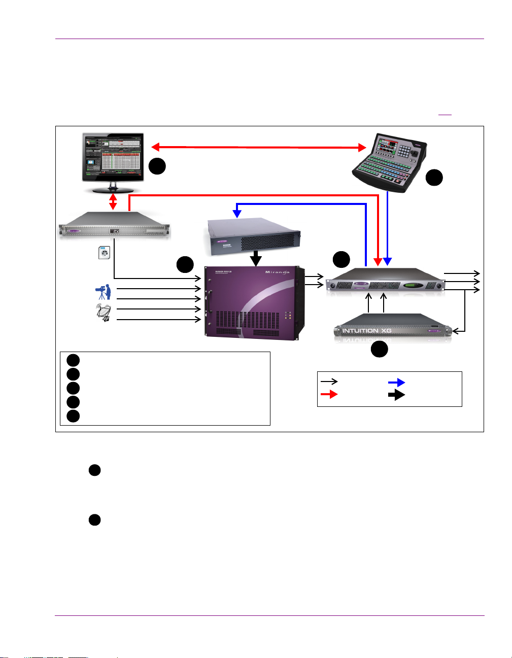
Functional overview of an iTX-MC System
iMC panel
iTX Desktop
iTX Output Server
Router Controller
Station Router
Imagestore 750
Intuition XG (optional)
Network, studio, live feeds
Video clips
Program
Preset
Automation control
Router control & tallies
Manual control
& tallies
F&K
iTX control
Video
Oxtel control
Clean
A
B
Nvision router
1
2
3
4
5
1
iTX channel playout automation
2
Video source inputs
3
A/B switching of video signals
4
A/B source mixing and local secondary event insertion
5
Optional downstream graphics insertion
control protocol
1
2
The iTX Master Control (iTX-MC) option integrates the Imagestore Master Control processor
(Imagestore 750 or Imagestore-Modular) and an iMC panel (iMC100, iMC200, or iMC300) with
a traditional iTX channel automation system, station router and router controller (figure 1-1).
Introduction
iTX channel playout automation: When the iTX-MC option is added to a system, iTX
still drives automation control by managing and playing the schedule’s events. However,
unlike traditional iTX systems, the iTX automation system controls the Imagestore 750
mixer as the playout device as well as an iTX Output Server.
Video source inputs: With the iTX-MC option, the iTX Output Server acts as a video
server source to the station router by providing the pre-recorded programme content, which
can also contain the usual secondary events like logos, voice-overs...etc.
The station router also receives SDI video inputs from various sources, including live
network feeds, studio feeds and the SDI output of the iTX Output Server.
iTX-MC User Guide 1-2
Figure 1-1. iTX-MC system architecture
Page 7

Introduction
345
A/B source mixing and local secondary event insertion: The Imagestore 750
provides the A/B switching of signals from the station router based on the scheduled events
being run by the iTX automation system, or the manual operations performed on the iMC
master control panel.
The Imagestore 750 also provides the ability to perform downstream insertion of logo or
voice-over assets which are native to the Imagestore 750.
Traditional master control integration: The iMC panel is directly connected to the
Imagestore 750 master control and channel branding processor via Ethernet. The
Imagestore 750 is fed A/B program sources by an upstream router, with control from playout
automation by an Ethernet connection. The router is controlled by the Imagestore 750 via
a NVISION 9000 controller.
The iMC master control panel provides operators with the manual control of the Imagestore
750’s PGM bus, which permits them to insert or override scheduled programming with live
incoming video.
Operators can also manually control the iTX schedule using the iMC panel’s Automation
Assist buttons (T
AKE NEXT, HOLD NEXT, CUE NEXT, SKIP NEXT).
Optional downstream graphics insertion: The Intuition XG co-processor is an
optional piece of equipment that can be used to insert rich branding graphics to the
Imagestore 750’s keyer layers.
iTX-MC User Guide 1-3
Page 8

Operational modes
iTX-MC has four modes of operation, which offer operators various levels of control over
the playout of scheduled and non-schedule content. The following section provide a brief
overview of each mode, while further chapters provide usage instructions:
• Fully Automated mode
• Automation Assist mode
• Manual Insert & Manual Override modes
Fully Automated mode
The iTX-MC’s Fully Automated mode allows the iTX automation system to fully control the
playout of iTX schedules, which may contain a combination of pre-recorded video clip
events from iTX and live content events from multiple video sources.
Fully Automated mode is ideal for situations where the exact timing of primary video events
is known in advance and the live video content is originating from different sources. Since
the timing of all of these primary events is known, a schedule containing these events can
be created and automation can run the schedule automatically by taking each event at a
precise time regardless of where the video content is coming from. When building the
schedule, live video source events are added to the schedule as master control primary
events.
See “iTX Master Control events” on page 1-6
3-1 for more information related to Fully Automation mode.
Introduction
and “Using Fully Automated mode” on page
Automation Assist mode
The iTX-MC’s Automation Assist mode allows operators to have full manual control of
scheduled events, even during the playout of a live broadcast. Using the iMC panel’s
Automation Assist buttons (C
Desktop’s Manual Control panel, operators can manually intervene and control the
channel’s scheduled primary events, including extending or truncating a scheduled live
playout event, which results in the advancement or bumping out of the next schedule
primary and secondary events.
Automation Assist mode is ideal for live event broadcasts where the duration of the live
events are unknown and the schedule contains primary video clip events that must be taken
to air, although not necessarily at a specific time.
See “iTX Master Control events” on page 1-6
manually control the iTX schedule” on page 4-1 for more information related to Automation
Assist mode.
iTX-MC User Guide 1-4
UE NEXT, TAKE NEXT, HOLD NEXT and SKIP NEXT) or the iTX
and “Using Automation Assist mode to
Page 9

Manual Insert & Manual Override modes
iTX-MC offers two modes that allow operators to manually insert a live video source during
an automated broadcast using the iMC panel: Manual Insert mode and Manual Override
mode. Typically this type of intervention is used when unforeseen emergency events occur
and a “newsflash” type interruption of the regularly scheduled broadcast is required.
The main difference between the two modes is the way in which the schedule’s playout is
resumed after the manual live event is finished. When using Manual Insert mode, the
automation system pauses the schedule’s programming during the live event and then
resumes playout from the point of interruption. Manual Override mode allows automation to
continue running the schedule (roll under), without displaying the schedule’s playout. Once
the live event is finished, the programme is resumed “in progress” or from where it would
have been had there not been a live event interruption.
See “Using Manual Insert and Manual Override modes” on page 5-1
Introduction
for more information.
iTX-MC User Guide 1-5
Page 10
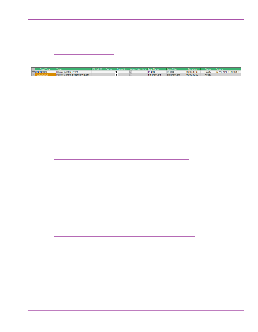
iTX Master Control events
iTX-MC introduces two new types of events that can be added to an iTX schedule:
• Master control primary events
• Master control secondary events
Figure 1-2. Example of a master control primary and secondary event in an iTX schedule
Master control primary events
Master control primary events are main video items added to an iTX schedule to enable the
iTX automation system to switch to and playout live content from any of the live video
sources available to the Imagestore 750 from the upstream router.
When adding a master control primary event, you must specify the precise live source to be
played out, the starting transition type and speed and the duration of the live event.
A master control primary event appears as primary event item in the iTX schedule grid and
is displayed as a block on the PGM track of the channel’s timeline.
See “Adding a master control primary event to a schedule” on page 3-2
information.
Introduction
for more
Master control secondary events
Master control secondary events represent logos, voice-overs or Macro recalls that are
native to the Imagestore 750.
Master control secondary events can be associated with any type primary event in the
schedule. However, since live video content from master control primary events is routed
directly to the Imagestore 750, it does not pass through the iTX Output Server where
traditional iTX logo and voice-over insertion events are normally applied. As such, master
control secondary events allow for logo and voice-over insertion using the Imagestore 750.
See “Adding a master control secondary event to a schedule” on page 3-4
information.
iTX-MC User Guide 1-6
for more
Page 11

2 ITX-MC SYSTEM CONFIGURATION
iTX-MC is an option that integrates an Imagestore 750 mixer and an iMC panel with a
traditional iTX channel automation system, station router and router controller.
For the most part, the iTX automation system must be installed and configured for normal
channel control and playout. Similarly, the Imagestore 750 and iMC panel are configured
for normal master control usage.
With that in mind, this document does not repeat general iTX, Imagestore or iMC system
installation and configuration procedures. Instead the following table summarizes the
installation and configuration of iTX-MC specific components that are required to use iTXMC in normal operating conditions. Further sections in this chapter provide instructions for
performing iTX-MC specific installation and configuration tasks.
Component Setup or configuration description
iTX Framework Server An iTX Framework Server must be available with iTX Database
Server, Locator Server and Media Watcher installed.
A valid iTX Master Control license and transition license must be
added to the iTX system.
See the iTX System Administrator Guide
instructions.
iTX Output Server The iTX Output Server software component must be installed and
configured for regular channel playout on the iTX Output Server
device. See the iTX System Administrator Guide
information and instructions.
The iTX-MC related configuration task includes enabling the CUE
TO FIRST FRAME setting on the Output Server. See page 2-19 for
instructions.
iTX-MC User Guide 2-1
for more information and
for more
Page 12

iTX-MC system configuration
Component Setup or configuration description
iTX Desktop Client The iTX Desktop Client application must be installed and
configured for regular channel playout. See the iTX Desktop
Operator’s Guide for more information and instructions.
iTX-MC related configuration tasks include:
• Installing or updating the iTX Desktop Client and Hard
Panel Controller software components. See page 2-3
more information and instructions.
• Configuring the iTX Hard Panel Controller component on
the iTX Desktop client computer. See page 2-4
for more
information and instructions.
• Installing and configuring the
ITX-MC PLUGIN within the iTX
Desktop application. See page 2-8 for instructions.
• Enabling the master control setting in the iTX Channel
Config See page 2-10
• Adding the
ITX MC LAYOUT to the iTX Desktop application.
for more information and instructions.
See page 2-6 for more information and instructions.
• Configuring and setting up the iTX MC layout’s Mixer
Mapper component. See page 2-11
for information and
instructions.
for
Imagestore 750
or
Imagestore-Modular
An Imagestore Master Control device must be configured to
receive input from a video source router.
See the Imagestore 750 User Manual
for more information and
instructions.
iMC panel Regardless of which model of iMC panel used (iMC100, iMC200,
or iMC300), the panel must be configured to control an
Imagestore 750 or Imagestore-Modular device. See the iMC
Master Control documentation (Oxtel series>Documentation) for
more information and instructions.
iTX-MC related configuration tasks include:
• Adding the hardware control panel to the MCS Panel
Configuration Editor and the IP address of the computer
hosting the iTX Desktop client must be specified. See page
2-17 for more information and instructions.
• Configure the panel’s Automation Assist buttons (H
OLD
NEXT, CUE NEXT, TAKE NEXT, SKIP NEXT) and the
Automation Off button.
Router & Router Controller Since the iTX automation system controls the router’s crosspoints
through the Imagestore 750, please consult the Imagestore 750
User Manual for more information and instructions of configuring
the Imagestore 750 and router controller.
iTX-MC User Guide 2-2
Page 13
iTX-MC system configuration
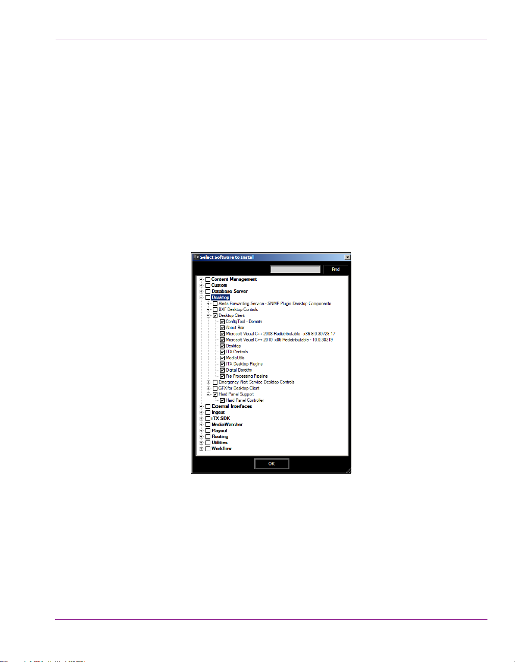
Installing or updating the iTX Desktop client software components
Install or update the iTX software to v2.3 SP3 or higher on the computer hosting the iTX
Desktop application to ensure that you have the most recent versions of the iTX Desktop
client and Hard Panel Controller components.
To install or update the required iTX Desktop client software components:
1. Open the iTX Suite 2.3 installer folder in Windows Explorer.
2. Run the iTX installer by right-clicking on the Setup.exe file and selecting the Run as
administrator command.
3. Click the Select Software button.
4. In the Select Software to Install window, enable the Desktop Client and Hard Panel
Controller options and click OK.
Then complete the installation or updates as required.
iTX-MC User Guide 2-3
Page 14
iTX-MC system configuration
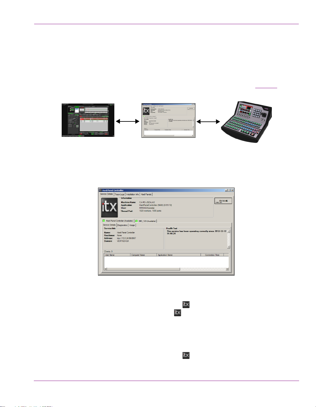
iTX Desktop iTX Hard Panel Controller
iMC panel
Configuring the iTX Hard Panel Controller
When iTX-MC is used in Automation Assist mode, the iMC panel (v.7.2.9 or later) is used
to manually control events scheduled for selected iTX playout channels.
This functionality is made possible by the iTX Hard Panel Controller, which is an iTX service
application that interfaces between the iTX Desktop application and the iMC panel. The iTX
Hard Panel Controller is run on the same computer as the iTX Desktop client (see page 2-3
for installation instructions).
Since the Hard Panel Controller is an iTX service, it has a service window which provides
information and status about the service and its clients. To run the iTX Hard Panel Controller
service between a specific iMC panel and the iTX Desktop, you must create a hard panel
configuration profile (see instructions below).
To access the iTX Hard Panel Controller service window:
1. Click the Windows Start button and navigate through the programs to ITX 2.0 > Hard
Panel Controller.
This activates the Hard Panel Controller icon in the Windows applications tray.
2. Right-click the Hard Panel Controller icon and select the Show command. The
Hard Panel Controller window appears.
To create a new hard panel configuration profile in the iTX Hard Panel Controller:
1. Click the Windows Start button and navigate through the programs to ITX 2.0 > Hard
Panel Controller.
This activates the Hard Panel Controller icon in the Windows applications tray.
iTX-MC User Guide 2-4
Page 15
iTX-MC system configuration
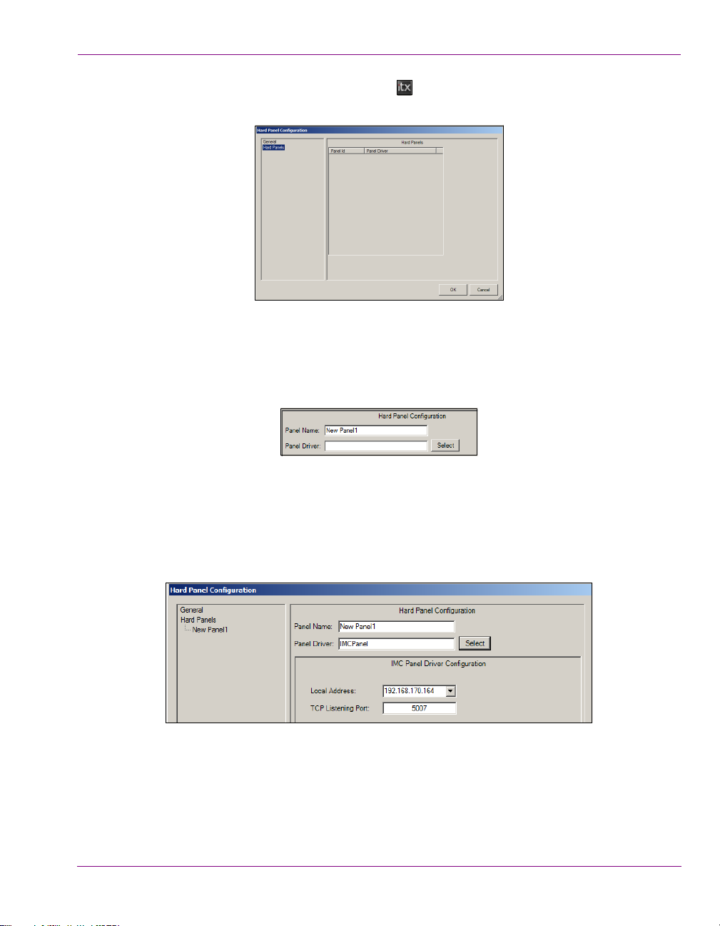
2. Right-click the Hard Panel Controller icon and select the Configuration
command. The Hard Panel Configuration window appears.
3. Right-click the Hard Panels heading and select the Add new Hard Panel command.
A new panel heading (New Panel1) is added as a sub-heading.
4. Select the New Panel heading and then type a name for the panel in the Panel Name field.
This name must be identical to the name given to the panel device when it was configured
using the MC Panel Configuration tool.
5. Click the Select button associated with the Panel Driver field, which opens the Select
Driver window.
6. Select IMCPanel from the Driver Name list and click OK.
The IMC Panel Driver Configuration section is added to the Hard Panel Configuration
pane and automatically fills in the Local Address (which is the IP address of the
computer hosting the iTX Desktop) and TCP Listening Port setting (5007).
7. Click OK to automatically save the hard panel’s configuration and close the Hard Panel
Configuration window.
iTX-MC User Guide 2-5
Page 16

iTX-MC system configuration
Installing and adding the iTX MC layout to the iTX Desktop
A global layout is provided especially for iTX-MC use in the iTX Desktop’s Channel Control
view. The iTX MC layout contains all of the typical channel control components, plus the
Mixer Mapper component (see page 2-11
To install and add the iTX MC layout to the iTX Desktop’s Channel Control view:
1. Open the iTX Suite 2.3 installer folder in Windows Explorer and navigate to:
ITX Install\Files\iTX Standard Layouts - v2.0
2. Run the INSTALL TEMPLATES MANUALLY.bat file to install the iTX MC global layout.
Open the iTX Desktop application.
3. From the same folder, run the INSTALL INPUT Mappings.bat file to install the
default input mappings for the iTX Desktop’s Mixer Mapper component.
4. Open the Manage Views dialog by right-clicking the Layout Selection Bar (bottom) and
select Manage Views.
5. Select the User View tab at the top of the Manage Views window. Then select the
Global Layout tab from the Add Layout from Object Store section.
).
6. In the Folders pane, select the System>Templates>1920x1080 folder.
iTX-MC User Guide 2-6
Page 17

iTX-MC system configuration
7. In the Layouts pane, select the iTX MC Layout Global layouts and click the <<Add button.
ITX MC (Global Layout) is now displayed in the Layouts in View pane.
8. Click OK and the iTX MC tab is added to the iTX Desktop’s Layout Selection Bar. When
the iTX MC tab is selected, the iTX MC layout appears featuring the Mixer Mapper
component.
iTX-MC User Guide 2-7
Page 18

iTX-MC system configuration
NOTE
Configuring the Master Control Plugin in the iTX Desktop
The iTX Desktop’s Master Control Plugin allows you to add master control primary and/or
secondary events to a schedule. See “iTX Master Control events” on page 1-6
description of master control events.
A valid iTX Master Control license must be installed on the iTX system for the Master
Control plugin to be visible and operational. Also, the Master Control Plugin must be
configured on a per channel basis.
To configure the Master Control plugin:
1. Open the iTX Desktop’s Engineering View and select the Channel Config tab.
2. Select the channel and then the Plugins tab.
3. Select the Master Control tab and the following Master Control Setup settings
become available.
for a
Figure 2-1. The Master Control Plugin’s configuration settings
Device Type Defines the type of hardware that the Master Control plugin will connect
to for this channel. Choose IS750Device.
iTX XPT Specifies the crosspoint on the Imagestore device that is selected when
the next item in the schedule is not a master control event. Normally, you
should specify the crosspoint that has the iTX Pandora video for that
channel. It is used only to put Pandora back in circuit when a primary
master control event ends. The default is 0.
Delay Specify the number of frames (positive or negative) by which to delay
commands sent to the IS-750. This compensates for latency in the
system and ensures that transitions on the mixer are frame accurate. The
default is 0.
iTX-MC User Guide 2-8
Page 19

iTX-MC system configuration
Manual Insert Default
Duration (secs)
Manual Insert Cue
Back Time (sec)
4. Click the Save button.
Specify the number of seconds to use as the default duration of an iTXMC manual insert. The default is 60.
Specify the number of seconds by which to cue back an event interrupted
by an iTX-MC manual insert. The default is 0.
iTX-MC User Guide 2-9
Page 20

iTX-MC system configuration
Enabling master control on the iTX Channel Config
For each of the iTX channels associated with an Imagestore 750 (master control enabled),
you must specify the Imagestore 750’s IP address in the Master Control property on
channel’s iTX Channel Config. The Master Control property allows the iTX Desktop’s Mixer
Mapper component to communicate directly with the Imagestore 750 associated with the
iTX channel.
1. Open the iTX Desktop’s Engineering View and select the Channel Config tab.
2. Select the channel that is associated with the Imagestore 750 and then the Channel tab.
3. Select the Channel Config 4 tab and specify the IP address of the Imagestore 750 in
the Master Control setting’s IP address field.
4. Repeat steps 2 and 3 for each of the master control enabled channels and then click
Close.
iTX-MC User Guide 2-10
Page 21

Setting up and using the Mixer Mapper
The Mixer Mapper is an iTX Desktop component that allows operators in a multi-channel
environment to use a single iMC panel station to manually control multiple iTX channels.
Figure 2-2. Mixer Mapper component of the iTX MC layout
The Mixer Mapper’s button identifies the iMC panel and allows operators to enable/disable
the Mixer Mapper’s functionality. iTX channels are “selected” in the Mixer Mapper, which
makes the channel control panel enabled. This means that operators are permitted to
perform manual control operations on that channel using the iMC panel’s Automation Assist
buttons.
When the Mixer Mapper is enabled and the iTX system’s currently selected channel is
control panel enabled, the iMC panel and the iTX Desktop become synchronized. The
functional implications of this synchronization are:
• When an operator selects a channel in the iTX Desktop’s Channel Selector that is
control panel enabled, the same channel is also selected on the iMC panel; and vice
versa.
• Regardless of where the channel selection occurs (iTX Desktop or the iMC panel), both
interfaces are immediately updated with the sources, labels and functionality available
to that particular channel.
• Automation Assist operations performed on the iMC panel are also reflected in the iTX
Desktop, and vice versa.
The following sections provide more information about setting up and using the Mixer
Mapper component:
• “Configuring the Mixer Mapper” on page 2-12
• “Using the Mixer Mapper” on page 2-15
iTX-MC system configuration
iTX-MC User Guide 2-11
Page 22

Configuring the Mixer Mapper
NOTE
Button only
(N
OT DISPLAYED setting)
Button & read-only list
(VIEW ONLY setting)
Button & interactive list
(VIEW AND EDIT setting)
The Mixer Mapper can be configured to appear in the iTX Desktop as a single button, or a
button with a view-only or interactive list containing the names of the iTX channels within
the current Channel view.
If the channel cannot be controlled by the iMC panel, the channel name in the channel list
is preceded by “N/A”. Also note that Edit channels cannot be controlled by a panel, so they
are also precede by “N/A” in the channel list.
Before using the Mixer Mapper, you must “select” which the iTX channels are available to
be control panel enabled in the Mixer Mapper. In other words, you must designates which
channels the iMC panel is able to perform manual control operations on when the Mixer
Mapper button is enabled.
iTX-MC system configuration
To configure the Mixer Mapper component’s desktop appearance and designate
specific iTX channels as control panel enabled:
1. With the iTX MC layout open in the iTX Desktop, enter Edit Mode by right-clicking in
an empty portion of the Layout selection bar and select Edit.
2. Type the administrative password in the Enter Password window and click OK.
The iTX MC layout now appears in Edit Mode.
3. Right-click the Mixer Mapper handles (small white boxes) and select Properties.
The Mixer Mapper Properties window appears.
iTX-MC User Guide 2-12
Page 23

iTX-MC system configuration
NOTE
4. Set the CHANNEL LIST DISPLAY property.
OT DISPLAYED When selected, the Mixer Mapper appears only as a button
N
in the iTX Desktop. The button only format requires less
desktop space, but operators do not have the ability to
select channels for panel control from within the desktop.
The selection of channels enabled for panel control must
be pre-configured in the Enabled Channels section of the
Mixer Mapper Properties window.
IEW ONLY When selected, the Mixer Mapper appears as a button and
V
a list that contains the names of the iTX channels within the
current Channel view. Channels that have been preconfigured as “selected” for panel control are highlighted in
the list. Although the channel list is displayed in the
desktop, operators cannot enable (select) or disable (deselect) channels for panel control because the list is “view
only”. Any changes to the channel selection must be
performed in the Enabled Channels section of the Mixer
Mapper Properties window.
IEW AND EDIT When selected, the Mixer Mapper appears as a button and
V
a list that contains the names of the iTX channels within the
current Channel view. The channels that have been preconfigured as “selected” for panel control are highlighted in
the list. Since the list is “editable”, operators can enable or
disable panel control on any channel by clicking the
channel’s name in the Mixer Mapper’s channel list.
Note that channels whose names are preceded with “N/A”
cannot be panel control enabled.
Changing the appearance of the Mixer Mapper component in the iTX Desktop (button only
vs. button and channel list) may require you to reorganize the placement of other
components in the iTX MC layout.
5. In the Enabled Channels section, identify the channel(s) that you want to be available
for panel control by dragging the channel from the Available Channels list and
dropping it onto the Selected Channels list.
iTX-MC User Guide 2-13
Page 24

iTX-MC system configuration
NOTE
When the Channel List Display property is set to VIEW ONLY or VIEW AND EDIT, the
channels listed in Selected Channels will be highlighted in the Mixer Mapper’s list.
Channels can be “selected” even if they do not have an Imagestore 750 configured.
However, the Mixer Mapper only highlights channels that have an Imagestore 750
configured and are control panel enabled.
6. Click OK.
7. Exit the iTX Desktop’s Edit Mode by right-clicking in an empty portion of the Layout
selection bar and selecting the Edit command.
iTX-MC User Guide 2-14
Page 25

Using the Mixer Mapper
Once the Mixer Mapper is properly configured with iTX channels that are control panel
enabled, operators simply have to click the Mixer Mapper button to activate or de-activate
panel control on selected the iTX channel.
Whether it’s configured as a single button on its own or associated with a channel list, the
functionality and appearance of the Mixer Mapper button is identical.
Figure 2-3 demonstrates that the Mixer Mapper is active (green) so that when the
iTXNTSC-1 channel is selected in the iTX Desktop’s channel selector on the iMC panel, the
iTX Desktop becomes in synch with the iMC panel and the iMC panel’s Automation Assist
buttons can be used to manually control the channel’s active schedule.
Figure 2-3. The Mixer Mapper is active
iTX-MC system configuration
The Mixer Mapper interface component provide operators with visual cues (color & text) to
indicate the current state of the Mixer Mapper and its associated components.
The background color of the Mixer Mapper button provides operators with a quick reference
to the current state of the Mixer Mapper for the selected channel:
Green The panel and desktop are connected to the same channel and channel
following is enabled.
Indicates that the Mixer Mapper component is active and the iTX Desktop
and the iMC panel are in synch. Also, the Automation Assist buttons on the
iMC panel are active. Operations performed to the selected channel using
the iTX Desktop will be reflected on the iMC panel, and vice versa.
Black The iMC panel and iTX Desktop are not enabled or the iTX MC layout is
in Edit mode.
Indicates that the Mixer Mapper is inactive. In this state, both the iTX
Desktop and the iMC panel are independent of each other (not in synch) and
operations performed on a channel in one will not be reflected on the other.
iTX-MC User Guide 2-15
Page 26

iTX-MC system configuration
Red No communication with the iMC panel.
Indicates that the Mixer Mapper component is active, but the iTX Desktop
and the iMC panel are not in synch, or that the selected channel cannot be
controlled from iTX Desktop or the iMC panel. Also, the Automation Assist
buttons on the iMC panel are not active.
The text or label on the Mixer Mapper button identifies the Imagestore channel that is
currently selected on the iMC panel. It can also identify the current state of the connection
between the iMC panel’s currently selected channel and the Mixer Mapper:
<Channel Name> The iMC panel’s channel name on its own indicates that the iMC panel is
reporting that it is connected to the same channel as the channel selected in
the iTX Desktop.
When a different channel is selected on the iMC panel, if the channel is
configured for panel control, the Mixer Mapper’s button updates to display
the new channel’s name.
NO PANEL Indicates that communication with the iMC panel has not been established.
To remedy, ensure that the Hard Panel Controller is properly configured and
that all physical connections are correct and properly fitted.
Panel
Disconnected
<Channel Name>
OUT OF SYNCH
<Channel Name>
Not Controllable
<Channel Name>
Slave
Indicates that the iMC panel is reporting that it has no channel selected.
Indicates that the iMC panel is reporting that it is connected to a channel that
is not the same channel as selected in the iTX Desktop.
Indicates that the iMC panel is reporting that it is connected to the same
channel as selected in the iTX Desktop, but the Mixer Mapper component is
inactive or that the channel is not enabled/selected for panel control.
Indicates the iMC panel is reporting that it is connected to the same channel
as selected in the iTX Desktop; the Mixer Mapper component is active and
that channel is enabled/selected for panel control, but the channel has Slave
duty for a Main/Backup iTX channel. Channel control in iTX is available only
for the Master duty, hence the Automation Assist buttons in the iTX Desktop
and on the iMC panel are not enabled for the selected channel.
iTX-MC User Guide 2-16
Page 27

iTX-MC system configuration
Configuring the iMC panel to support iTX Automation
Assuming that the Master Control Panel (iMC panel v.7.2.9 or later) has been installed and
configured to control the Imagestore 750, the following procedure describes the additional
steps required to configure the master control panel to support iTX Automation.
1. Open the MCS Panel Configuration Editor by selecting the Windows Start button
and navigating the programs menu to Miranda > Master Control > MCSPanelConfig.
2. Select File > Open. Navigate to
and open the panel’s configuration file.
The panel’s configuration profile appears in the MCS Panel Configuration Editor.
3. In General tab, ensure that the Panel Name setting is accurate and that Imagestore
is enable as the Master Control Type setting.
C:\Program Files (x86)\Miranda\Master Control\bin\
iTX-MC User Guide 2-17
Page 28

iTX-MC system configuration
4. Select the Advanced tab and then select the Enable iTX Integration setting in the
Automation section. This causes the iTX Integration section to automatically appear.
5. In the iTX IP Address field, specify the IP address of the computer hosting the iTX
Hard Panel Controller and iTX Desktop client.
6. Select File>Write Config To Panel.
7. Click Yes when asked if you want to save the changes.
8. Click OK when the Config File Save window appears.
9. A window appears informing you that the device must be reset after a configuration
update. Click Yes to restart the device.
iTX-MC User Guide 2-18
Page 29

iTX-MC system configuration
NOTE
Video Clip 1 Master Control Primary 1 Video Clip 2
The video clip is cued and
its first frame is displayed on
the iTX Output Server’s output.
The Master Control primary
event (live source) is currently
playing out on air.
Master Control Primary 1 Video Clip 2 Video Clip 3
The video clip is cued, but its
first frame cannot be displayed
on the iTX Output Server’s output.
The video clip is currently
playing out on air.
Activating the Enable Cue-to-First-Frame setting on the iTX Output Server
While the Imagestore 750 is busy playing out a master control primary event (live source
event), the iTX Output Server‘s E
frame of next the cued video clip to be displayed on the iTX Output Server’s SDI output.
Using a a multi-viewer display, operators can then see the first frame of the next video clip
and have confidence in what will actually be taken to air.
Figure 2-4. Illustration of an iTX timeline that uses the CTFF option to preview the next cued clip
NABLE CUE TO FIRST FRAME (CTFF) option allows the first
By default, the E
NABLE CUE TO FIRST FRAME setting is disabled. Instructions are provided
below for activating the option. Once activated, CTFF is automatically triggered when:
• A video clip event in the schedule is automatically cued by TxPlay
• The operator manually cues the next video clip event in the schedule using the iTX
Desktop’s C
UE NEXT control or the SELECTED ITEM CONTROL
• The operator manually cues the next video clip event in the schedule by pressing the
iMC panel’s CUE NEXT button.
Figures 2-4 and 2-5 demonstrate that CTFF will only occur if TxPlay is idle; meaning that
the iTX Output Server is not currently processing or playing out a video clip. More precisely,
CTFF only occurs when:
• No clips are present on the timeline (e.g. at start-up)
• The last clip on the timeline has finished playing more than two seconds ago
• While displaying bars at startup
Figure 2-5. CTFF does not occur if the current playout event is also a video clip from the iTX Output Server
As per current functionality, the last frame of the previous clip will be repeated if no clip is cued.
iTX-MC User Guide 2-19
Page 30

iTX-MC system configuration
NOTE
To activate the ENABLE CUE TO FIRST FRAME setting:
1. On the iTX Output Server device, open the iTX Output Server window.
2. Select the Engineering tab.
3. Click the E
NABLE CUE TO FIRST FRAME button to ensure that the LED is green.
See “Cue to first frame” in the iTX System Administrator Guide for complete information
regarding this feature.
iTX-MC User Guide 2-20
Page 31

3 USING FULLY AUTOMATED MODE
iTX-MC’s Fully Automated mode allows the iTX Automation system to take full control
over the playout of iTX schedules that contain a mixture of traditional iTX events as well as
Master Control primary and secondary events.
Fully Automated mode is recommended for situations where the exact timing of primary
video events is known in advance and when transitions between back-to-back live video
events is required.
Figure 3-1
events (e.g. BITC PAL SD), as well as back-to-back live video feeds as Master Control
events (e.g. IN-061, IN-068) and Master Control secondary events. Since the timing of all
of these primary events is known, automation can run the schedule without the need for any
manual intervention. Each event is cued and taken at precise times regardless of the source
of the video content.
demonstrates a schedule that contains a mixture of pre-recorded video clip
Figure 3-1. An iTX schedule that contains a mixture of clips and primary & secondary master control events
Information and instructions for adding and setting master control events in an iTX
channel’s schedule are provided in the following sections:
• “Adding a master control primary event to a schedule” on page 3-2
• “Adding a master control secondary event to a schedule” on page 3-4
iTX-MC User Guide 3-1
Page 32

Using Fully Automated mode
Adding a master control primary event to a schedule
Master control primary events are main video items added to an iTX schedule to enable the
iTX automation system to switch to and playout from any of the live video sources available
to the Imagestore 750 from the upstream router.
To add a master control primary event to an iTX schedule:
1. Select the Master Control tab in the Content Selector to display the Master Control Palette.
2. Ensure that the Master Control palette’s Selection pane contains the Imagestore 750’s
video sources.
If the video sources are not listed, please verify the channel’s Master Control
configuration setting, the Master Control Plugin’s Setup configuration and/or the
network connection to the Imagestore 750 device.
3. Optional: Specify a name for the master control primary event in the Title field.
4. Optional: Set the event’s duration in the Duration field.
The Duration field specifies the duration of the next event to be added to a channel. The
event’s Duration setting can also set/edited after it has been added to the schedule.
5. Drag and drop a source from the Selection pane onto the iTX schedule grid.
A master control primary event item is added to the schedule.
When a master control primary event is added from the Master Control palette, it will initially
be given the specified duration, a default transition (Cut) and the video source’s name will
appear in the Item Name column. If specified in the Master Control Palette, the event’s
name also appears in the Item Title column. The Source column displays the router’s
crosspoint information.
The event’s properties may be edited by selecting the event in the schedule, which displays
the event’s current property settings in the Event Editor.
iTX-MC User Guide 3-2
Page 33

Using Fully Automated mode
NOTE
NOTE
Set the title of the
master control event.
Add a note to the
master control event.
Set the master control
event’s Time Mode to:
Change the duration of
the master control event.
• Auto
• Fixed
• Start -
• Start +
• End -
• End +
• Fixed End
• Join In Progress
Displays the scheduled
Start Time of the
master control event.
Displays the name of
the source for the
master control event.
Optional: Set the Manual
property to enable the manual
start for the master control
event.
The event’s status.
Setting and editing a master control primary event’s properties
Once a master control primary event is added to a schedule, you can set/edit the event’s
Transi tion settings by clicking the event’s transition symbol in the Schedule grid. The Select
transition window appears and allows you to set the transition’s duration, rate and style.
If you intend on using Automation Assist mode (page 4-1) to control the schedule, ensure
that the iTX channel’s event transition rate setting (slow, medium, fast) is consistent with the
iMC panel’s transition rate settings.
Similarly, you can edit the event’s duration value by clicking on the Duration setting in the
Schedule grid. The Change duration tool appears and you can change the event’s current value.
Just like other iTX video events, selecting a master control primary event in the Schedule
Grid or Timeline displays a set of standard event properties in the Event Editor. These
properties can be edited and applied to the scheduled event.
iTX-MC User Guide 3-3
Since there are no properties specific to master control primary events listed on the Event
Editor, we ask that you refer to the iTX Desktop Operator Manual for full descriptions and
instructions on setting these event properties.
Sources cannot be changed within in a scheduled master control primary event.
Page 34

Using Fully Automated mode
Select Logo as the secondary event type.
Enter the name of the Logo. See
Select the layer on the device to which the
event will be assigned.
Specify if the event is intended to be a
turn on, turn off or duration based.
When Duration enabled (above), specify
the duration of the next event to be added
to the schedule. Only specify the In and
Out transition type and duration.
When On is enabled (above), specify the
In transition type and duration.
When Off is enabled (above), specify the
Out transition type and duration.
for more information.
page 3-5
Select VO as the secondary event type.
Enter the name of the VO. See
Disabled.
Specify if the event is intended to be a
turn on, turn off or duration based.
When Duration enabled (above), specify
the duration of the next event to be added
to the schedule. Only specify the In and
Out transition type and duration.
When On is enabled (above), specify the
In transition type and duration.
When Off is enabled (above), specify the
Out transition type and duration.
page 3-5
for more information.
Adding a master control secondary event to a schedule
Master control secondary events represent logos, voice-overs or Macro recalls that are
native to the Imagestore 750.
Master control secondary events can be associated with any type primary event in the
schedule, however their main function is to provide logo and voice-over insertion on the live
video content coming from master control primary events.
To add a master control secondary event to an iTX schedule:
1. Select the iTX_MC Secondary tab in the Content Selector to display the Master Control
Secondary Event Palette.
2. In the Secondary Type field, use the up/down control to select either Logo, Macro or VO.
3. The following screen captures demonstrate that the palette’s fields change depending
upon the Secondary Type selected. As such, please complete the appropriate fields.
iTX-MC User Guide 3-4
Page 35

Using Fully Automated mode
Select Macro as the secondary event type.
Enter the name of the VGPI.
Disabled.
Disabled.
4. Select the Drag from Here control at the bottom of the palette. Drag the control from
the palette and drop it onto a primary event in the channel’s Schedule Grid or the PGM
track on the Timeline.
This creates a new Master Control Secondary Event in the schedule, with a Title and Event
ID as specified (defaulting to the name of the Logo/VO), as well as a specified duration.
Logos appear on the CG track in the Timeline, voice-over events appear on the VO track
and Macros appear on the VGPI track.
Browsing the media content of the Imagestore 750
When creating a master control secondary event, you must type the name of the logo or
voice-over asset that is stored on the Imagestore 750 in the Logo Name or VO Name
property of the iTX_MC Secondary palette (see page 3-4).
Currently there is no way of browsing or selecting the assets on the Imagestore 750 directly
from with the iTX Desktop application. As such, we recommend that you use the procedure
below to browse the asset inventory of the Imagestore 750 using its web service. This will
ensure that you have the exact name of the desired asset.
To browse the media content of an Imagestore 750 device:
1. Open a web browser and type the IP address of the Imagestore 750 in the address bar
(e.g. http:\\10.14.3.10) to open the Imagestore 750 Web Page.
2. Click the Login button. Enter the password and click the Log In button.
iTX-MC User Guide 3-5
Page 36

Using Fully Automated mode
3. Select Media Management from the left-hand menu.
4. Browse the Graphics Files category for logo assets and the Easyplay Files category for
the Voice-over assets. Note that you cannot open or preview assets from this interface.
5. Take note of the exact name of the asset. Once you are finished browsing, click Logout
and close the web browser to finish the session.
Setting and editing master control secondary event properties
Once a master control secondary event is added to a schedule, you can set/edit the event’s
Transi tion settings by clicking the event’s transition symbol in the Schedule grid. The Select
transition window appears and allows you to set the transition’s duration, rate and style.
iTX-MC User Guide 3-6
Page 37

Using Fully Automated mode
Type the title of the
master control event.
Add a note to the
master control event.
Set the master control
event’s Time Mode to:
Change the duration of
the master control event.
• Auto
• Fixed
• Start -
• Start +
• End -
• End +
• Fixed End
• Join In Progress
Displays the scheduled
Start Time of the
master control secondary
Displays the name of
the master control
secondary event.
Optional: Set the Manual
property to enable the manual
start for the master control
event.
secondary event determines
the properties displayed here .
Each property is described
page 3-4
on
The event’s status.
event.
The type of master control
Similarly, you can edit the event’s duration value by clicking on the Duration setting in the
Schedule grid. The Change duration tool appears and you can change the event’s current value.
When a master control secondary event is selected in the Schedule Grid or Timeline, the
Event Editor displays a set of standard and event type specific properties. These
properties can be edited and applied to the scheduled event by clicking the Store Changes
button.
iTX-MC User Guide 3-7
Page 38

4 USING AUTOMATION ASSIST MODE TO
NOTE
MANUALLY CONTROL THE ITX SCHEDULE
The iTX-MC’s Automation Assist mode allows operators to use the iMC panel’s
Automation Assist buttons to manually intervene and control the channel’s scheduled
primary events.
The iMC panel’s Automation Assist buttons consist of:
• Cue Next: Cues the item that follows the current on-air item.
• Take Next: Takes to air the item that follows the current on-air item.
• Hold Next: Holds the item that follows the current on-air items.
• Skip Next: Causes the next scheduled item not to take place.
The Take button on the iMC panel is for a separate purpose and should not be confused
with Automation Assist’s Take Next button.
Automation Assist mode is ideal for live event broadcasts where the duration of the live
source events (master control events) are unknown and the schedule contains primary clip
events that must be taken to air, although not necessarily at a specific time.
The unpredictably of the live event’s start and end times means that operators must
manually control the cue and take of the next clip event in the schedule. Using the iMC
panel’s Automation Assist buttons, the operator is able to put a hold on the next scheduled
clip event and then manually take it to air when required. This may require taking the clip or
live event earlier or delaying it beyond the events’ original scheduled duration settings.
Once the event is taken to air, the iTX automation system resumes control of running the
schedule and plays out the subsequent events, including scheduled master control events.
The following section provide information and instructions for using the iTX-MC’s
Automation Assist mode:
• “Preparing to use iTX-MC’s Automation Assist mode” on page 4-2
• “Using iTX-MC’s Automation Assist mode” on page 4-2
iTX-MC User Guide 4-1
Page 39

Using Automation Assist mode to manually control the iTX schedule
Preparing to use iTX-MC’s Automation Assist mode
Before attempting to use the iTX-MC’s Automation Assist mode, operators should ensure
that the following pre-requisites are satisfied:
1. Ensure that the iMC panel’s Automation Assist buttons (C
NEXT and SKIP NEXT) have been properly configured.
2. Ensure that Automation is enabled on the iMC panel.
3. Ensure that the iMC panel’s transition rate settings (slow, medium, fast) are consistent
with the schedule’s event transition rate settings.
4. (Optional) Enable the Output Server’s Cue-to-First-Frame option if you want to view the
first frame of the next iTX clip event in the schedule on the Imagestore 750’s Preset
channel (see page 2-19
).
UE NEXT, TAKE NEXT, HOLD
Using iTX-MC’s Automation Assist mode
The following high-level steps describe how to use the iMC panel’s Automation Assist
buttons to manually control the iTX schedule’s playout:
1. Select the channel in the iTX Desktop.
2. Ensure that the Mixer Mapper button is enabled and that the channel is “selected” in
the Mixer Mapper. If both are true, then the iTX Desktop and the iMC panel will be in
synch and operations on the iMC panel will be reflected in the iTX Desktop.
3. Load the schedule in the iTX Desktop.
4. As the schedule’s events are playing out, you can press the iMC panel’s Automation
Assist buttons to manually control events in the current schedule (hold, cue, take or
skip the next schedule event).
The following sections provides instructions for performing three of the most common
control tasks using the iTX-MC’s Automation Assist mode:
• “Forcing the next scheduled primary event to play immediately” on page 4-2
• “Delaying the next scheduled primary event’s playout” on page 4-4
• “Skipping the next scheduled primary event” on page 4-6
Forcing the next scheduled primary event to play immediately
Regardless of what type of event is currently on air, operators can use the iMC panel’s
Automation Assist buttons to manually force the next scheduled events to be taken to air.
Depending upon the state of the next items in the schedule, operators can use one of the
following methods to force the next items to playout immediately:
• “Next items are already cued (Take Next only)” on page 4-3
• “Next items are not cued (Cue Next & Take Next)” on page 4-3
• “Next items are not cued (Take Next only)” on page 4-4
iTX-MC User Guides 4-2
Page 40

Using Automation Assist mode to manually control the iTX schedule
NOTE
NOTE
Next items are already cued (Take Next only)
Regardless of what type of event is currently on air, if the next primary item in the playlist is
already cued, pressing the iMC panel’s Take Next button immediately plays out the next
primary item and any associated secondary items that are cued by the same time.
If the Mixer Mapper is enabled for the channel, the changes to the previous and current
items’ timings and duration are immediately reflected on the iTX Desktop’s schedule grid
and timeline.
Operators should be aware that iTX does not wait for secondary items that cannot be cued
in time; nor does it cue the primary items following the item being forced on air. As such,
after an operator uses the iMC panel’s Take Next button, they should use the iMC panel’s
UE NEXT button to manually cue the next scheduled items and then check that all required
C
items are cued before performing a subsequent TAKE NEXT operation.
Next items are not cued (Cue Next & Take Next)
If the next items are not already cued, we recommend that the operator press the iMC
panel’s C
Take Next button.
When CUE NEXT is clicked for a short item (one with a duration of less than 20 seconds),
iTX cues any following primary items that are due to start within the next 20 seconds and
have a status of READY; it also cues secondary items that are due to start within the same
period. This is to ensure all items are cued in time to play out. Any item that is unable to be
cued (i.e. if it is not ready) is not played out.
Once the items are cued, the operator must press the iMC panel’s Take Next button, which
immediately plays out the next primary item and any associated secondary items that are
cued by the same time.
If the Mixer Mapper is enabled for the channel, the changes to the previous and current
items’ timings and duration are immediately reflected on the iTX Desktop’s schedule grid
and timeline.
UE NEXT button to manually cue the next scheduled items before pressing the
Operators should be aware that iTX does not wait for secondary items that cannot be cued
in time; nor does it cue the primary items following the item being forced on air. As such,
after an operator uses the iMC panel’s Take Next button, they should use the iMC panel’s
UE NEXT button to manually cue the next scheduled items and then check that all required
C
items are cued before performing a subsequent TAKE NEXT operation.
iTX-MC User Guides 4-3
Page 41

Using Automation Assist mode to manually control the iTX schedule
NOTE
Next items are not cued (Take Next only)
If the next items are not already cued and they must go to air immediately, there may not
be enough time to perform a Cue Next operation. In such a case, pressing the iMC panel’s
Take Next button forces iTX to automatically cue the next primary item and any associated
secondary items that have the same start time and then plays out the items. This results in
a short execution delay before the actual items replace what is currently playing out on air.
Operators should be aware that iTX does not wait for secondary items that cannot be cued
in time; nor does it cue the primary items following the item being forced on air. As such,
after an operator uses the iMC panel’s Take Next button, they should use the iMC panel’s
UE NEXT button to manually cue the next scheduled items and then check that all required
C
items are cued before performing a subsequent TAKE NEXT operation.
Delaying the next scheduled primary event’s playout
Since live source events often have unpredictable start and end times, operators must be
ready at any time to take the next scheduled item without delay. A powerful technique for
achieving this is to put the next scheduled item on hold using the iMC panel’s Hold Next
button.
The Hold Next button temporarily suspends the item that follows the current on-air items
and continues to play the current on air items until a Take Next operation is executed.
There are two common scenarios for holding the next scheduled events:
• “Delaying the start of a live source event” on page 4-4
• “Delaying the ending of a live source event” on page 4-5
Delaying the start of a live source event
When the next scheduled item is a live source event, the live content may not be ready to
go on air at the scheduled time. For example, the scheduled coverage of a live press
conference is delayed. In such a case, the operator will keep playing the current on air item
until the press conference is ready to begin.
To accomplish this, the operator presses the iMC panel’s Cue Next and then Hold Next
buttons to ready the next scheduled item (live source event), but prevent it from playing.
This puts a hold on the remaining items in the schedule until the live source event is ready.
When it is time to join the live source event, the operator simply presses the iMC panel’s
Take Next button and the iTX automation system resumes control of running the schedule
by playing out the subsequent events.
iTX-MC User Guides 4-4
Page 42

Using Automation Assist mode to manually control the iTX schedule
Figure 4-1 demonstrates that the primary and secondary master control events (IN-072 and
N07) are cued, but placed on hold. The clip that is currently on air (BITC PAL SD) keep playing
and the schedule will keep bumping out until the operator executes a Take Next operation.
Figure 4-1. Delaying the start of the next live source event using the iMC’s Hold Next operation
Delaying the ending of a live source event
When a live source event is currently on air, it might be scheduled but in reality its exact
ending time might be unknown. For example, the coverage of a sport event which includes
the playout of commercials only when the play allows for a pause or break. In such a case,
the operator presses the iMC panel’s Cue Next and then Hold Next buttons to ready and
delay the playout of the next scheduled event (commercial clip). The live source event
keeps playing and delays the remaining scheduled events until the operator presses the
iMC panel’s Take Next button. The iTX automation system resumes control of running the
schedule by playing out the subsequent events.
Figure 4-2
secondary events that are currently on air and scheduled to playout from 04:40:19:00 to
4:40:43:00, followed immediately by the video clip, BITC PAL SD. Pressing the iMC panel’s
Hold Next button delays the playout of the next item and updates the schedule’s
progressive timing until a Take Next operation is executed.
demonstrates that items IN-072 and N072 are master control primary and
Figure 4-2. Delaying the end of the live source event by holding the next scheduled item
iTX-MC User Guides 4-5
Page 43

Using Automation Assist mode to manually control the iTX schedule
Skipping the next scheduled primary event
Pressing the iMC panel’s Skip Next button causes the next scheduled event not to take
place and the event is immediately removed from the timeline and schedule grid.
iTX-MC User Guides 4-6
Page 44

5 USING MANUAL INSERT AND MANUAL OVERRIDE MODES
iTX-MC offers two modes for using the iMC panel to manually insert a live video source
during the playout of an automated schedule: Manual Insert mode and Manual Override
mode.
These types of manual interventions are typically used when unforeseen emergency events
occur and the operator is required to “breakaway” from the regular schedule to broadcast
the live coverage of the event.
The main difference between these two modes is the way in which the schedule’s playout
is resumed after the manual live event is finished.
The following sections provide information and instructions for using the iTX-MC’s Manual
Insert and Manual Override modes:
• “Manually inserting a live source into a scheduled broadcast” on page 5-2
• “Manually overriding a scheduled broadcast with a live source” on page 5-4
iTX-MC User Guide 5-1
Page 45

Using Manual Insert and Manual Override modes
Manually inserting a live source into a scheduled broadcast
The iTX-MC’s Manual Insert mode instructs the automation system to pause or hold the
schedule’s programming while the live source event is played out on air. Once the live
source event has finished, the scheduled playout resumes from the precise point of
interruption.
Figure 5-1
currently on air (IN-068) gets split in the timeline and the channel’s playout transitions to a
Master Control Event named “Manual Insert”, which is added to both the schedule grid and
timeline.
The Manual Insert event has an initial default duration, however as the event continues to
playout the manual insert item expands and delays the remaining scheduled events until
the manual insert event is ended by the operator. Once the operator manually ends the
manual insert event, the on air playout transitions back to the scheduled playout event,
which resumes from the exact point of interruption, or from a point as configured in the
channel configuration.
demonstrates that when a manual insert is executed on the iMC panel, the event
Figure 5-1. A “Manual Insert” breaks into regular programming and resumes from the point of interruption
iTX-MC User Guides 5-2
Page 46

Using Manual Insert and Manual Override modes
Preparing to use iTX-MC’s Manual Insert mode
Before attempting to use the iTX-MC’s Manual Insert mode, operators should ensure that
the following pre-requisites are satisfied:
1. Ensure that the iMC panel’s Automation Assist buttons (C
NEXT and SKIP NEXT) have been properly configured.
2. Ensure that Automation is enabled on the iMC panel (turned on).
3. Ensure that the iMC panel’s transition rate settings (slow, medium, fast) are consistent
with the typical schedule event’s transition rate settings.
4. (Optional) Enable the Output Server’s Cue-to-First-Frame option if you want to view the
first frame of the next iTX clip event in the schedule on the Imagestore 750’s Preset
channel (see page 2-19
).
UE NEXT, TAKE NEXT, HOLD
Using iTX-MC’s Manual Insert mode
To manually insert of a live source into the schedule playout using the iMC panel:
1. Ensure that Automation Enabled button on the iMC panel is active
2. Select the channel in the iTX Desktop or on the iMC panel.
3. Ensure that the Mixer Mapper button is enabled and that the channel is “selected” in
the Mixer Mapper. If both are true, then the iTX Desktop and the iMC panel will be in
synch and operations on the iMC panel will be reflected in the iTX Desktop.
4. Load the schedule in the iTX Desktop and the automation system will playout the
scheduled events.
5. When you are required to break into the programming:
• Press the Preset bus button on the iMC panel that represents the desired video
source and then press the panel’s Tak e button (not
or,
• Press the PGM bus button on the iMC panel that represents the desired video
source.
The on air playout immediately begins to transition to the live video source.
6. When you want to exit the “manual insert” event, press the iMC panel’s Take Next
button and the scheduled events resume.
the Take Next button).
(On).
iTX-MC User Guides 5-3
Page 47

Using Manual Insert and Manual Override modes
Manually overriding a scheduled broadcast with a live source
The iTX-MC’s Manual Override mode instructs the iTX automation system to keep running
the schedule’s programming while the live source event is played out on air. Once the live
source event has finished, the broadcast rejoins the schedule already in progress. In other
words, from where it would have been had there not been a live event interruption.
Figure 5-2
scheduled events continue running in the schedule grid and timeline, but the channel’s
actual playout transitions to a Master Control Event named “Roll Under”, which is added to
added to the schedule grid and timeline.
The Roll Under event has an initial default duration, however as the event continues to
playout the Roll Under item expands in the timeline without delaying the other scheduled
events. When the operator chooses to end the Roll Under event, the channel’s playout
transitions back to the scheduled playout event by rejoining the event as if no interruption
had occurred.
demonstrates that when a manual override is executed on the iMC panel, the
Figure 5-2. A “Manual Override” breaks into regular programming and joins the schedule “in progress”
Preparing to use iTX-MC’s Manual Override mode
Before attempting to use the iTX-MC’s Manual Override mode, operators should ensure
that the following pre-requisites are satisfied:
1. Ensure that Automation Enabled button on the iMC panel is de-activated.
2. Ensure that the iMC panel’s transition rate settings (slow, medium, fast) are consistent
with the typical schedule event’s transition rate settings.
3. (Optional) Enable the Output Server’s Cue-to-First-Frame option if you want to view the
first frame of the next iTX clip event in the schedule on the Imagestore 750’s Preset
channel (see page 2-19
iTX-MC User Guides 5-4
).
Page 48

Using Manual Insert and Manual Override modes
NOTE
Using iTX-MC’s Manual Override mode
To manually insert of a live source into the schedule playout using the iMC panel:
1. Ensure that Automation is disabled on the iMC panel (turned off).
2. Select the channel in the iTX Desktop or on the iMC panel.
3. Ensure that the Mixer Mapper button is enabled and that the channel is “selected” in
the Mixer Mapper. If both are true, then the iTX Desktop and the iMC panel will be in
synch and operations on the iMC panel will be reflected in the iTX Desktop.
4. Load the schedule in the iTX Desktop and the automation system will playout the
scheduled events.
5. When you are required to break into the programming:
• Press the Preset bus button on the iMC panel that represents the desired video
source and then press the panel’s Tak e button (not
or,
• Press the PGM bus button on the iMC panel that represents the desired video
source.
The on air playout immediately begins to transition to the live video source and the iTX
schedule will keep running as usual.
6. When you want to exit the “Roll Under” event, press the Preset bus button on the iMC
panel that corresponds to the iTX source and then press the panel’s Take button (not
the Take Next button). This cancels the roll under and the channel’s playout is
transitioned back to regular programming.
the Take Next button).
Be sure to re-enable automation on the iMC panel, otherwise subsequent Master Control
Primary events will fail.
iTX-MC User Guides 5-5
 Loading...