

Page 1

ITX DELIVERY MANAGER
INTEGRATED CONTENT DELIVERY
Configuration and Setup Guide
iTX v2.6
2015-04-13
Page 2

Notices
Copyright and Trademark Notice
Copyright © 2013–2015, Grass Valley USA, LLC. All rights reserved.
Belden, Belden Sending All The Right Signals, and the Belden logo are trademarks or
egistered trademarks of Belden Inc. or its affiliated companies in the United States and
r
other jurisdictions. Grass Valley USA, LLC, Miranda, iTX, Delivery Manager, iTX Core,
Colossus, Missing Materials Manager, Workflow Service, Workflow Application Service,
Media Watcher, OPUS, SmartClient, PinPoint and TXPlay are trademarks or registered
trademarks of Grass Valley USA, LLC. Belden Inc., Grass Valley USA, LLC, and other parties
may also have trademark rights in other terms used herein.
Terms and Conditions
Please read the following terms and conditions carefully. By using iTX documentation, you
agree to the following terms and conditions.
Grass Valley hereby grants permission and license
manuals for their own internal business use. Manuals for Grass Valley products may not be
reproduced or transmitted in any form or by any means, electronic or mechanical, including
photocopying and recording, for any purpose unless specifically authorized in writing by
Grass Valley.
A Grass Valley manual may have been revised to reflect changes made to the product
during its manufac
product. Care should be taken to ensure that one obtains the proper manual version for a
specific product serial number.
Information in this document is subject to change without
commitment on the part of Grass Valley.
Warranty information is available in the Support section of the Grass Valley Web site
ww.grassvalley.com).
(w
turing life. Thus, different versions of a manual may exist for any given
to owners of iTXs to use their product
notice and does not represent a
Title Delivery Manager Configuration and Setup Guide
Software Version v2.6
Revision 2015-04-13, 18:08
ii
Page 3

Table of Contents
1 About Delivery Manager . . . . . . . . . . . . . . . . . . . . . . . . . . . . . . . . 1
What is Delivery Manager?. . . . . . . . . . . . . . . . . . . . . . . . . . . . . . . . . . . . . . . . . . . . . . . . . . . . . . . . . 1
Delivery Manager’s Endpoints . . . . . . . . . . . . . . . . . . . . . . . . . . . . . . . . . . . . . . . . . . . . . . . . . . . . . 1
Delivery Manager’s Modes of Operation. . . . . . . . . . . . . . . . . . . . . . . . . . . . . . . . . . . . . . . . . . . . 4
Content Changed (or Drop Box) Mode . . . . . . . . . . . . . . . . . . . . . . . . . . . . . . . . . . . . . . . . . 4
Search Media (or Missing Materials) Mode. . . . . . . . . . . . . . . . . . . . . . . . . . . . . . . . . . . . . . 4
Manual (or Export) mode . . . . . . . . . . . . . . . . . . . . . . . . . . . . . . . . . . . . . . . . . . . . . . . . . . . . . . 5
Modes of Operation and Endpoints . . . . . . . . . . . . . . . . . . . . . . . . . . . . . . . . . . . . . . . . . . . . 6
Delivery Manager and Workflows . . . . . . . . . . . . . . . . . . . . . . . . . . . . . . . . . . . . . . . . . . . . . . . . . . 6
Post Media Import Workflows. . . . . . . . . . . . . . . . . . . . . . . . . . . . . . . . . . . . . . . . . . . . . . . . . . 6
Delivery Manager’s Distribution and Resilience Models . . . . . . . . . . . . . . . . . . . . . . . . . . . . . 7
Load balanced system . . . . . . . . . . . . . . . . . . . . . . . . . . . . . . . . . . . . . . . . . . . . . . . . . . . . . . . . . 8
Endpoint monitoring system . . . . . . . . . . . . . . . . . . . . . . . . . . . . . . . . . . . . . . . . . . . . . . . . . . 9
2 Installing Delivery Manager . . . . . . . . . . . . . . . . . . . . . . . . . . . . 11
Installing the Delivery Manager service. . . . . . . . . . . . . . . . . . . . . . . . . . . . . . . . . . . . . . . . . . . .11
What’s next? . . . . . . . . . . . . . . . . . . . . . . . . . . . . . . . . . . . . . . . . . . . . . . . . . . . . . . . . . . . . . . . . . . . . .12
3 Configuration Profiles and Endpoint Tabs . . . . . . . . . . . . . . 15
Creating a New Configuration Profile. . . . . . . . . . . . . . . . . . . . . . . . . . . . . . . . . . . . . . . . . . . . . .15
Basic Steps for Adding an Endpoint . . . . . . . . . . . . . . . . . . . . . . . . . . . . . . . . . . . . . . . . . . . . . . .15
About Endpoint Configuration Tabs. . . . . . . . . . . . . . . . . . . . . . . . . . . . . . . . . . . . . . . . . . . . . . .17
Generic Endpoint Configuration Settings. . . . . . . . . . . . . . . . . . . . . . . . . . . . . . . . . . . . . .17
Removing a Configuration Profile . . . . . . . . . . . . . . . . . . . . . . . . . . . . . . . . . . . . . . . . . . . . . . . . .19
4 Adding Network Share Endpoints . . . . . . . . . . . . . . . . . . . . . . 21
Adding a CIFS Endpoint. . . . . . . . . . . . . . . . . . . . . . . . . . . . . . . . . . . . . . . . . . . . . . . . . . . . . . . . . . .21
Configuring a CIFS Endpoint in Content Change (Drop Box) Mode . . . . . . . . . . . . .21
Configuring a CIFS Endpoint in Search Media Mode . . . . . . . . . . . . . . . . . . . . . . . . . . .22
Adding a CIFS Endpoint in Manual Mode . . . . . . . . . . . . . . . . . . . . . . . . . . . . . . . . . . . . . .23
CIFS Endpoint Details Reference . . . . . . . . . . . . . . . . . . . . . . . . . . . . . . . . . . . . . . . . . . . . . .23
Adding an FTP Endpoint . . . . . . . . . . . . . . . . . . . . . . . . . . . . . . . . . . . . . . . . . . . . . . . . . . . . . . . . . .24
Adding a Pitch Blue Endpoint . . . . . . . . . . . . . . . . . . . . . . . . . . . . . . . . . . . . . . . . . . . . . . . . . . . . .26
5 Adding 3rd Party Endpoints . . . . . . . . . . . . . . . . . . . . . . . . . . . . 27
Adding a DIVA Endpoint . . . . . . . . . . . . . . . . . . . . . . . . . . . . . . . . . . . . . . . . . . . . . . . . . . . . . . . . . .27
Prerequisites for DIVA Endpoints in Manual Mode . . . . . . . . . . . . . . . . . . . . . . . . . . . . .27
Configure DIVA to restore media to iTX . . . . . . . . . . . . . . . . . . . . . . . . . . . . . . . . . . . . . . . 27
iii
Page 4

Table of Contents
Configure DIVA to archive media . . . . . . . . . . . . . . . . . . . . . . . . . . . . . . . . . . . . . . . . . . . . . 28
Configure the default Opus store . . . . . . . . . . . . . . . . . . . . . . . . . . . . . . . . . . . . . . . . . . . . . 29
Configure DIVA for partial restores . . . . . . . . . . . . . . . . . . . . . . . . . . . . . . . . . . . . . . . . . . . 29
Configuring a DIVA Endpoint . . . . . . . . . . . . . . . . . . . . . . . . . . . . . . . . . . . . . . . . . . . . . . . . .30
Adding MassTech Endpoints . . . . . . . . . . . . . . . . . . . . . . . . . . . . . . . . . . . . . . . . . . . . . . . . . . . . . .32
Adding a PathFire Endpoint. . . . . . . . . . . . . . . . . . . . . . . . . . . . . . . . . . . . . . . . . . . . . . . . . . . . . . .34
Prerequisites for PathFire Endpoints . . . . . . . . . . . . . . . . . . . . . . . . . . . . . . . . . . . . . . . . . .34
Configuring a PathFire Endpoint . . . . . . . . . . . . . . . . . . . . . . . . . . . . . . . . . . . . . . . . . . . . . .35
Adding Ardome Endpoints . . . . . . . . . . . . . . . . . . . . . . . . . . . . . . . . . . . . . . . . . . . . . . . . . . . . . . .36
Adding FlashNet Endpoints . . . . . . . . . . . . . . . . . . . . . . . . . . . . . . . . . . . . . . . . . . . . . . . . . . . . . . .37
Prerequisites for FlashNet Endpoints in Manual Mode . . . . . . . . . . . . . . . . . . . . . . . . .37
Configuring a FlashNet Endpoint . . . . . . . . . . . . . . . . . . . . . . . . . . . . . . . . . . . . . . . . . . . . .37
6 Adding Core Endpoints . . . . . . . . . . . . . . . . . . . . . . . . . . . . . . . . 39
About the Core Endpoint . . . . . . . . . . . . . . . . . . . . . . . . . . . . . . . . . . . . . . . . . . . . . . . . . . . . . . . . .39
Core Endpoint Asset Deletion. . . . . . . . . . . . . . . . . . . . . . . . . . . . . . . . . . . . . . . . . . . . . . . . .40
Preparing the Database for Core Endpoints. . . . . . . . . . . . . . . . . . . . . . . . . . . . . . . . . . . . . . . .40
Running the batch files . . . . . . . . . . . . . . . . . . . . . . . . . . . . . . . . . . . . . . . . . . . . . . . . . . . . . . .41
Generic Steps for Adding a Core Endpoint. . . . . . . . . . . . . . . . . . . . . . . . . . . . . . . . . . . . . . . . .42
Additional Configurations for Colossus Systems . . . . . . . . . . . . . . . . . . . . . . . . . . . . . . . . . . .44
Importing Business Metadata from a Colossus system . . . . . . . . . . . . . . . . . . . . . . . . .44
Registering new media from a Colossus systems. . . . . . . . . . . . . . . . . . . . . . . . . . . . . . .46
Registering Business Metadata from a Colossus systems . . . . . . . . . . . . . . . . . . . . . . .46
Import Media via the CIFS endpoint from a Colossus system . . . . . . . . . . . . . . . . . . .46
Additional Configurations for iTX 1.4 Systems . . . . . . . . . . . . . . . . . . . . . . . . . . . . . . . . . . . . .47
Registering new media from an iTX 1.4 system . . . . . . . . . . . . . . . . . . . . . . . . . . . . . . . .47
Importing Media via the CIFS endpoint from an ITX 1.4 system. . . . . . . . . . . . . . . . .47
Additional Configurations for Both Colossus and iTX 1.4 Systems. . . . . . . . . . . . . . . . . . .48
Importing an asset with media Missing Materials Manager. . . . . . . . . . . . . . . . . . . . .48
Import Media via the DIVArchive endpoint . . . . . . . . . . . . . . . . . . . . . . . . . . . . . . . . . . . .48
Import media via the FTP endpoint . . . . . . . . . . . . . . . . . . . . . . . . . . . . . . . . . . . . . . . . . . .49
Configuring Omneon Video Servers and FTP Endpoints . . . . . . . . . . . . . . . . . . . . . . . . . . . .49
7 Configuring the Server Controller . . . . . . . . . . . . . . . . . . . . . . 51
Configuring Server Controller to run a named instance of Delivery Manager. . . . . . . .51
Adding a named instance to Server Controller . . . . . . . . . . . . . . . . . . . . . . . . . . . . . . . . . . . . .52
Restarting an iTX Service. . . . . . . . . . . . . . . . . . . . . . . . . . . . . . . . . . . . . . . . . . . . . . . . . . . . . . . . . .53
8 Setting Up Delivery Manager Resilience. . . . . . . . . . . . . . . . . 55
How to Set Up a Load Balanced System . . . . . . . . . . . . . . . . . . . . . . . . . . . . . . . . . . . . . . . . . . .55
How to Set Up Endpoint Monitoring System. . . . . . . . . . . . . . . . . . . . . . . . . . . . . . . . . . . . . . .56
Cloning a configuration profile . . . . . . . . . . . . . . . . . . . . . . . . . . . . . . . . . . . . . . . . . . . . . . .56
9 Finalizing the Delivery Manager System . . . . . . . . . . . . . . . . 59
Additional Setup for Search Media mode . . . . . . . . . . . . . . . . . . . . . . . . . . . . . . . . . . . . . . . . . .59
Install the Missing Materials Manager service . . . . . . . . . . . . . . . . . . . . . . . . . . . . . . . . . .59
iv
Page 5

Configuration and Setup Guide
Configure the Missing Materials Manager . . . . . . . . . . . . . . . . . . . . . . . . . . . . . . . . . . . . .59
Configuring Missing Materials Manager for the Core Endpoint . . . . . . . . . . . . . . . . .60
Disabling Media Watcher’s Media Cache De-archive functionality . . . . . . . . . . . . . 60
Additional Setup for Manual/Export Mode . . . . . . . . . . . . . . . . . . . . . . . . . . . . . . . . . . . . . . . .61
Install the iTX Workflow service . . . . . . . . . . . . . . . . . . . . . . . . . . . . . . . . . . . . . . . . . . . . . . .61
Configure Delivery Manager Workflows . . . . . . . . . . . . . . . . . . . . . . . . . . . . . . . . . . . . . . .61
Configuring the Manual Archive workflow . . . . . . . . . . . . . . . . . . . . . . . . . . . . . . . . . . . . 62
Configuring a Manual Restore workflow . . . . . . . . . . . . . . . . . . . . . . . . . . . . . . . . . . . . . . 63
Configuring the ShotList Export workflow . . . . . . . . . . . . . . . . . . . . . . . . . . . . . . . . . . . . 65
Optional Setup and Configuration . . . . . . . . . . . . . . . . . . . . . . . . . . . . . . . . . . . . . . . . . . . . . . . .65
Additional Services . . . . . . . . . . . . . . . . . . . . . . . . . . . . . . . . . . . . . . . . . . . . . . . . . . . . . . . . . . .65
Processing Associated XML Metadata Files . . . . . . . . . . . . . . . . . . . . . . . . . . . . . . . . . . . .66
Deep Analysis During Proxy Generation . . . . . . . . . . . . . . . . . . . . . . . . . . . . . . . . . . . . . . .66
10 User Operations . . . . . . . . . . . . . . . . . . . . . . . . . . . . . . . . . . . . . . . 67
iTX Desktop Transfer Status Display . . . . . . . . . . . . . . . . . . . . . . . . . . . . . . . . . . . . . . . . . . . . . . .67
Job Monitoring. . . . . . . . . . . . . . . . . . . . . . . . . . . . . . . . . . . . . . . . . . . . . . . . . . . . . . . . . . . . . . . . . . .68
Filtering jobs . . . . . . . . . . . . . . . . . . . . . . . . . . . . . . . . . . . . . . . . . . . . . . . . . . . . . . . . . . . . . . . . .70
Viewing more details and displaying keyframes . . . . . . . . . . . . . . . . . . . . . . . . . . . . . . .71
Changing priority of a job. . . . . . . . . . . . . . . . . . . . . . . . . . . . . . . . . . . . . . . . . . . . . . . . . . . . .71
Changing required by data and time of a job . . . . . . . . . . . . . . . . . . . . . . . . . . . . . . . . . .71
Direct Monitoring of MassTech Jobs . . . . . . . . . . . . . . . . . . . . . . . . . . . . . . . . . . . . . . . . . .72
Manually Archiving and Restoring Jobs. . . . . . . . . . . . . . . . . . . . . . . . . . . . . . . . . . . . . . . . . . . .73
Partial Restore jobs (DIVA only) . . . . . . . . . . . . . . . . . . . . . . . . . . . . . . . . . . . . . . . . . . . . . . . . . . .75
Viewing a partially restored media file. . . . . . . . . . . . . . . . . . . . . . . . . . . . . . . . . . . . . . . . .75
Exporting ShotLists from the iTX Desktop and SmartClient . . . . . . . . . . . . . . . . . . . . . . . . .78
Exporting ShotList XML . . . . . . . . . . . . . . . . . . . . . . . . . . . . . . . . . . . . . . . . . . . . . . . . . . . . . . . . . . .79
Delivery Manager
Appendix A Delivery Manager Feature Set . . . . . . . . . . . . . . . . . 81
Delivery Manager Feature Set . . . . . . . . . . . . . . . . . . . . . . . . . . . . . . . . . . . . . . . . . . . . . . . . . . . . .81
Supported Features by Endpoint. . . . . . . . . . . . . . . . . . . . . . . . . . . . . . . . . . . . . . . . . . . . . . . . . .82
Appendix B Troubleshooting. . . . . . . . . . . . . . . . . . . . . . . . . . . . . . 85
Basic System Checks. . . . . . . . . . . . . . . . . . . . . . . . . . . . . . . . . . . . . . . . . . . . . . . . . . . . . . . . . . . . . .85
Monitoring Status and Health. . . . . . . . . . . . . . . . . . . . . . . . . . . . . . . . . . . . . . . . . . . . . . . . . . . . .86
Core Endpoint Connection Failure . . . . . . . . . . . . . . . . . . . . . . . . . . . . . . . . . . . . . . . . . . . .86
Running Diagnostics on the Delivery Manager Service . . . . . . . . . . . . . . . . . . . . . . . . . . . . .86
Generating Trace Logs in Delivery Manager . . . . . . . . . . . . . . . . . . . . . . . . . . . . . . . . . . . . . . .87
Viewing trace logs from the Delivery Manager Service . . . . . . . . . . . . . . . . . . . . . . . . .87
Creating a log file from Delivery Manager. . . . . . . . . . . . . . . . . . . . . . . . . . . . . . . . . . . . . 88
Viewing trace logs from the iTX Desktop . . . . . . . . . . . . . . . . . . . . . . . . . . . . . . . . . . . . . .88
Monitoring Active Jobs in Delivery Manager. . . . . . . . . . . . . . . . . . . . . . . . . . . . . . . . . . . . . . .89
Verifying the Database Update. . . . . . . . . . . . . . . . . . . . . . . . . . . . . . . . . . . . . . . . . . . . . . . . . . . .89
Verifying the 'Trigger On' table is present. . . . . . . . . . . . . . . . . . . . . . . . . . . . . . . . . . . . . .89
Verifying the Stored Procedures are present. . . . . . . . . . . . . . . . . . . . . . . . . . . . . . . . . . .90
Verifying the required functions are present. . . . . . . . . . . . . . . . . . . . . . . . . . . . . . . . . . .90
Verifying the Service Broker is present. . . . . . . . . . . . . . . . . . . . . . . . . . . . . . . . . . . . . . . . .90
v
Page 6

Table of Contents
Contact Us . . . . . . . . . . . . . . . . . . . . . . . . . . . . . . . . . . . . . . . . . . . . . . . 91
vi
Page 7

This chapter explains role of the Delivery Manager module as iTX’s media delivery and asset
registration tool, as well as outline its architecture, supported endpoints, operational
modes and failure resilience models.
Summary
What is Delivery Manager? . . . . . . . . . . . . . . . . . . . . . . . . . . . . . . . . . . . . . . . . . . . . . . . . . . . . . . . . . . . . 1
Delivery Manager’s Endpoints . . . . . . . . . . . . . . . . . . . . . . . . . . . . . . . . . . . . . . . . . . . . . . . . . . . . . . . . . 1
Delivery Manager’s Modes of Operation . . . . . . . . . . . . . . . . . . . . . . . . . . . . . . . . . . . . . . . . . . . . . . . 4
Delivery Manager and Workflows . . . . . . . . . . . . . . . . . . . . . . . . . . . . . . . . . . . . . . . . . . . . . . . . . . . . . 6
Delivery Manager’s Distribution and Resilience Models . . . . . . . . . . . . . . . . . . . . . . . . . . . . . . . . . 7
What is Delivery Manager?
Delivery Manager is an iTX service that retrieves and manages the processing of media and
assets that have been stored on, or delivered by, third-party content management systems.
Delivery Manager uses automated workflows to manage end to end schedule-driven
content delivery, which eliminates the need for a number of labor-intensive user tasks that
are normally required to prepare new media for playout.
About Delivery Manager
Delivery Manager uses custom software plug-ins, called ‘endpoint drivers”, to interface
directly with third party media archives, content stores and network repositories. Each
plug-in is designed to interface with a specific type of content storage or archive system
and actively searches for and retrieves media from these endpoints as and when they are
required for playout.
Delivery Manager’s Endpoints
The supported endpoint types can perform a range of content management operations,
such as:
• Monitoring external network locations (i.e. drop folders)
• Acquiring assets when they are placed into the drop folder
• Working with content management software to retrieve media required for broadcast
and archiving media that is no longer required.
Once Delivery Manager has been configured to use specific endpoints, the retrieval and
archiving of media can be triggered manually by an operator or automatically by a
scheduling system, via iTX Missing Materials Manager or an iTX Workflow, as required.
1
Page 8
About Delivery Manager
Delivery Manager’s Endpoints
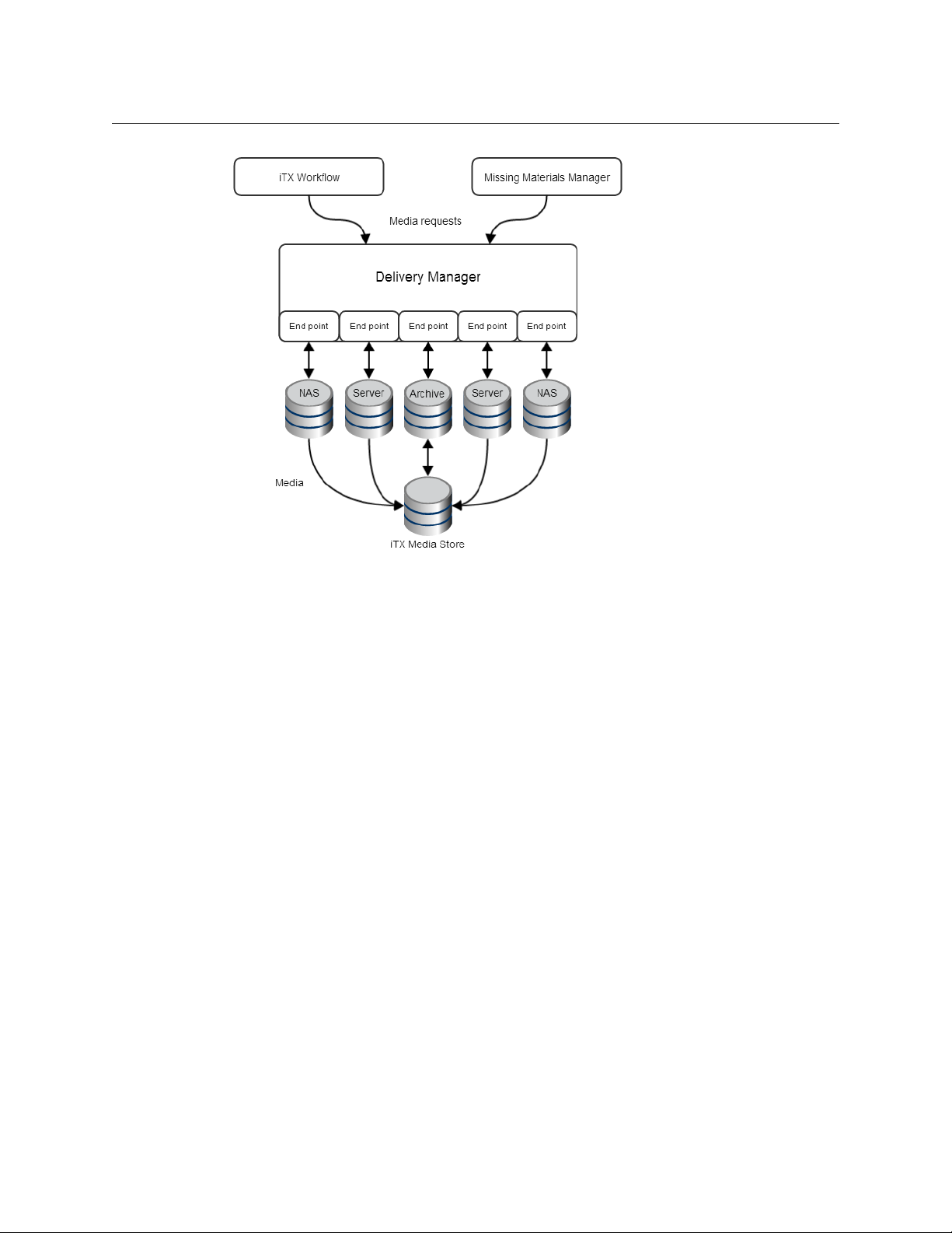
Fig. 1-1: Overview of the relationship between Delivery Manager, Workflow, Missing Material
Manager, the endpoints and the iTX media store.
The available endpoint drivers are:
• FTP (File Transfer Protocol), which includes
• Ascent Media Pitch Blue Archive
• Grass Valley K2
• CIFS (Common Internet File Systems), which includes
• SMB (Server Message Block)
• Signiant Media Exchange Archive
• Front Porch Digital DIVArchive
• DG PathFire Media Distribution and Management System
• MassTech Archive Solutions
• Viz Ardome Media Management System
•SGL FlashNet Archive
• Core endpoint
For more information Delivery Manager’s content management features and which ones
each endp
oint supports, see Delivery Manager Feature Set, o
n page 83.
2
Page 9

Delivery Manager
Configuration and Setup Guide
Each of these endpoints can be categorized in one of three ways, based on what type of
content archive, delivery systems or protocols they interface with, as described in the table
below:
Endpoint category Description
Network share endpoints Network share endpoints use an established IT network file
transfer protocol to monitor shared directories within a
network and transfer any files placed there using the standard
IT transfer methods. These are:
Third party archive and
content store endpoints
•FTP
The FTP endpoint can also be confi
Omneon Spectrum video servers.
•CIFS
The CIFS endpoint can be configured to access content on
Omneon M
edia Grid servers.
These endpoints interface directly to either a proprietary third
ty media archive or storage management application.
par
gured to access content on
In these cases, Delivery Manager's endpoints do not access the
st
ored files directly themselves, they simply query and make
transfer requests to the third party system which then handles
delivery of the media to an iTX Location.
The third party system may use a standard IT file transfer
od to execute the copying of the stored files to a specified
meth
iTX location, or it may 'restore' the requested media to a
network shared location that is part of the archive or storage
system, where Delivery Manager can then transfer the file into
iTX.
Depending on the system, separa
te asset metadata (in the
form of an XML file) may also be requested for retrieval and
transfer into iTX.
These endpoints are:
• Front Porch Digital DIVArchive
• DG PathFire Media Distribution and Management System
• MassTech Archive Solutions
• Viz Ardome Media Management System
• Ascent Media Pitch Blue Archive (using the FTP protocol)
• Signiant Media Exchange Archive (using the CIFS protocol)
•SGL FlashNet Archive
Core endpoint (for legacy
media management systems)
Since there are major differences between iTX 2.x and the older
iTX 1.4 and Colossus database structures, these systems cannot
be integrated. Instead, Delivery Manager has a special
endpoint called the Core endpoint that interfaces with these
legacy systems (which are sometimes referred to as Core
systems).
3
Page 10

About Delivery Manager
Delivery Manager’s Modes of Operation
Delivery Manager’s Modes of Operation
Depending on the endpoint driver being used, Delivery Manager can react to content
delivered to the monitored locations, actively seek content required for schedules or be
manually controlled by an operator. The mode of operation is defined by the selected
workflow or mode option in the endpoint configuration profile.
Content Changed (or Drop Box) Mode
This mode uses Delivery Manager's own internal workflow engine to determine which new
media files need to be registered or updated and at what time.
Content Changed mode requires that a networ
k share is configured as a monitored
location within the appropriate endpoint configuration. Delivery Manager monitors the
location for the presence of new or updated files. Delivery Manager processes new content
telligently, prioritizing material required for playout.
in
When new or updated files are detected, Delivery Manager does one of the following:
File status Delivery Manager action
File is required by a currently active
schedule
New file that is not yet required by
y known schedule
an
An updated version of a file that
eady exists in iTX
alr
File not yet required for playout The updated version of the file remains in the monitored
Delivery Manager moves the file to an iTX store and
es the database with the new asset's information
updat
and availability by placing the task in the active jobs
queue.
Delivery Manager creates an Asset Record in the
database. In order to avoid unnecessary network
bandwidth, the file will not be processed until required.
When the file appears in a schedule it will then be
transferred to an iTX location and the Asset Record
updated.
Delivery Manager updates the Asset Record for that file.
If the new version of the file is required for playout it will
be transferred to iTX and the original version will be
deleted.
location un
til it is required
The internal workflow that handles all Content Changed Mode actions needs to be selected
in the configuration options for the endpoint’s configuration profile, using the Content
Changed Workflow field.
Search Media (or Missing Materials) Mode
When configured in Search Media mode, the endpoint responds to “Find Content” requests
from Delivery Manager clients. When a search request is received, the CIFS driver searches for
any configured file type with the same name as the search request in the configured search
folder, and any of its sub folders (if configured), excluding any specifically configured exclude
folders. If a matching file is found, the driver generates a block of Asset XML detailing the media,
and returns it to Delivery Manager.
4
Page 11

The Missing Materials Manager can be configured to query Delivery Manager’s endpoints
when they attempt to locate and import the media required by channels that are not
currently located within iTX.
Once found, Missing Materials Manager then triggers a workflow that creates the new asset
(and its new location) in the iTX database, so that the media can be copied to an iTX
location. The workflow then requests the Delivery Manager endpoint to import the actual
media file.
The internal workflow that handles all Search Media mode actions needs to be selected in
the endpoint configuration profile, using the Cache Content Workflow field.
For more information on the additional setup required to operated in Search Media mode,
Additional Setup for Search Media mode, on page 63.
see
Manual (or Export) mode
In a busy and complex playout facility, manual media management might often be needed.
System administrators or media managers may need to free up space on content stores to
allow new content to be ingested. Late arriving content may need to be processed quickly
by hand, rather than queued in a job list, or last minute schedule changes may require
media to be pulled into the system rapidly.
Delivery Manager
Configuration and Setup Guide
Delivery Manager therefore allows users with CIFS endpoints to move media assets in and
out of the system on an ad-hoc basis.
These manually triggered jobs are initiated by action buttons on the Asset Layout of the iTX
Desktop or SmartClient:
• Move a clip to an externally managed third party archive system.
• Restore a clip from an externally managed third party archive system.
The following additional jobs may only be carried out in conjunction with a DIVArchive
system:
• Partial Restore of a clip from an external archive (DIVA Only).
• Export of a ShotList to an external location (usually a network share) outside of iTX
(DIVA Only).
Unlike the Content Changed and Search Media modes, no workflows are required to
perform these manual operations.
For more information on the additional setup required to operated in manual or Export
mode, see
Additional Setup for Manual/Export Mode, on page 65.
5
Page 12

About Delivery Manager
Modes of Operation and Endpoints
Modes of Operation and Endpoints
The table below shows which modes each endpoint supports:
Content Changed
Endpoint driver
mode
Search Media mode
Manual (export)
mode
CIFS
FTP
Diva
MassTech
PathFire
Ardome
FlashNet
Core
Delivery Manager and Workflows
Depending on the task its performing, Delivery Manager uses one of two workflow
systems.
• To trigger automated workflow operations (ca
internal workflow engine.
• To transfer media (and any associated metadata) t
Delivery Manager uses the ITX Workflow service.
Custom workflows (in the form of XML files) can also be cr
enhance Delivery Manager’s functionality. These workflows may provide the ability to
process different types of content and trigger other jobs (such as QC or file verification) to
prepare media for playout.
lled ‘jobs’), Delivery Manager uses its
o the iTX content store and database,
eated in iTX Workflow to further
Post Media Import Workflows
The Post Media Import process is a series of jobs triggered by a workflow following the
import of a new piece of media into Delivery Manager. This workflow runs internally for all
endpoints and therefore all media import jobs, which includes:
• Generation of proxy media copies for SmartClient and Desktop viewing.
• Generation of key frames for viewing in SmartClient.
• Deep analysis of the media file for extraction of metadata about the media.
Note: The Post Media Import workflow is added to all endpoints by
default and is part of the standard Delivery Manager installation, but
requires FPP Transcode Service to function.
To generate proxy media, the Proxy Generation Service is required.
6
Page 13
Configuration and Setup Guide
Delivery Manager’s Distribution and Resilience Models
Delivery Manager can be installed on one or more framework servers, each running one or
more instances of the service. Each instance of the service requires its own configuration
profile and each configuration profile can monitor multiple endpoints in different modes, in
order to manage different groups of content sources.
iTX can apply a single asset template (also known as clip templates) per monitored
ectory, so that media of different resolutions is deposited in separate (and appropriately
dir
named) folders, each with their own configured endpoint. You can apply an iTX media asset
templa
te to all clips, so that they are registered with the same characteristics.
Delivery Manager
For example, if you acquire both HD and SD med
be placed in a folder named “SD” and HD media should be placed in a folder named “HD”.
Each folder should have its own endpoint to monitor it, as it then applies the appropriate
asset template.
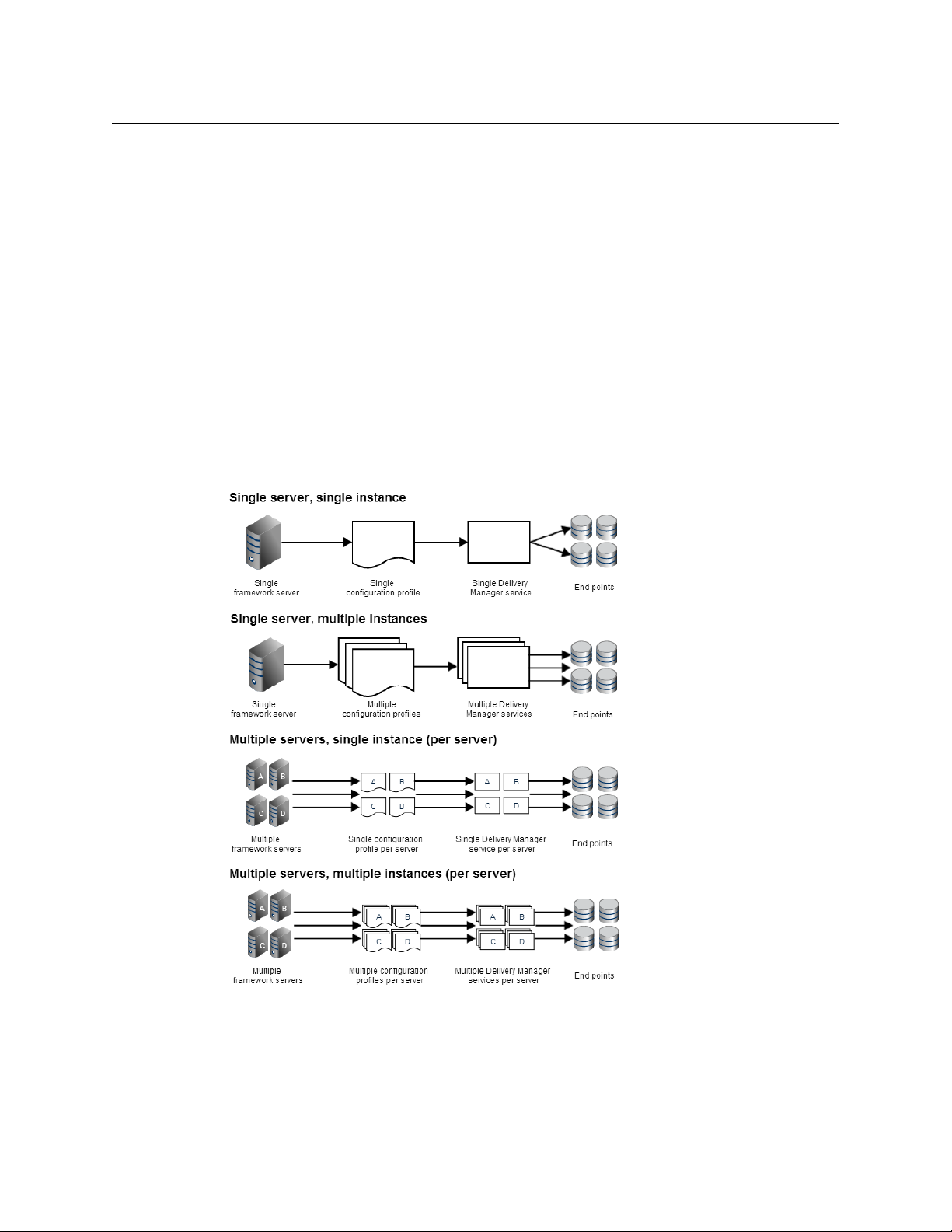
Figure 1-2 below illustrates the different combinations of server, configuration profiles,
instances and endpoints that can be used.
ia using a drop box, then SD media should
Fig. 1-2: Distribution models for single and multiple servers.
These different distribution models can also be used to provide uninterrupted service in
the event of software or hardware failure. Whether you are running multiple instances on a
single server or you have multiple servers, Delivery Manager can be configured to provide
one of two resilience models.
7
Page 14
About Delivery Manager
Load balanced system
Load balanced system
Delivery Manager’s workload can be balanced by spreading the monitored endpoints
across multiple instances of the service. Some degree of load balancing can be achieved by
running multiple instances of Delivery Manager on a single server, but ideally the
monitored endpoints should be spread across instances running on their own framework
server.
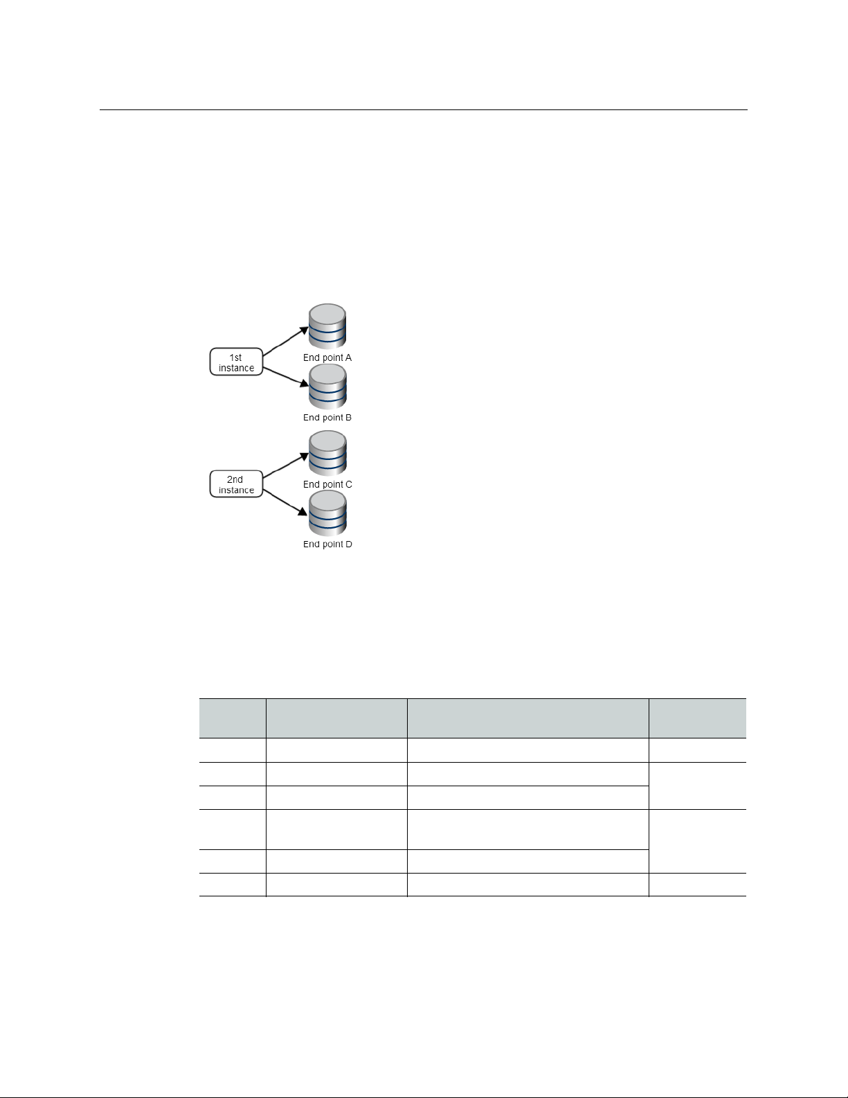
This is illustrated in Figure 1-3 below, where four endpoints (A to D) are shared between
two instances of Delivery Manager.
Fig. 1-3: Four endpoints load balanced between two instances of the Delivery Manager service.
By distributing your endpoints across multiple instances of Delivery Manager you reduce
the workload on each individual instance. Where each instance is also on a different
framework server, the workload is better distributed.
The table below shows how the number of servers and instances of Delivery Manager
ovide a sliding scale of load balancing effectiveness.
pr
Load balancing
Servers Instances Endpoints
One One Multiple in a single configuration profile Poor
One Multiple Multiple per configuration profile
One Multiple One per configuration profile
Multiple Multiple per server Multiple per configuration profile, per
ser
ver
Multiple Multiple per server One per configuration profile, per server
Multiple One per server One per server Best
effectiveness
Good
Better
8
Page 15
Endpoint monitoring system
In order to create an endpoint monitoring system you need to have Delivery Manager
running on two framework servers, using identical configuration profiles. When two
instances with the same name are started, the one that started first becomes the main (or
promoted) instance and the one that started second becomes the backup instance.
Delivery Manager
Configuration and Setup Guide
The backup instance monitors the main instance and if the mai
n instance stops responding,
the backup instance will promote itself and all jobs pass over to it. The backup will remain
as the promoted instance from that point on, even if the original main instance is restored.
The relationship is not hierarchical and
name under the control of one Delivery Manager instance.
it is not possible to have two instances with the same
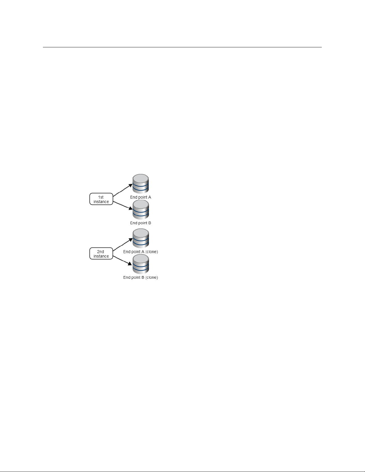
Figure 1-4 below shows the same two endpoints (A and B) are configured on two instances
of Delivery Manager. Cloning endpoints reduces the risk of an individual endpoint failure
using media transfers to stall.
ca
Fig. 1-4: Endpoint monitoring each instance must be running on a different framework server.
9
Page 16

About Delivery Manager
Endpoint monitoring system
10
Page 17

Installing Delivery Manager
This chapter explains how to install the Delivery Manager service itself.
Summary
Installing the Delivery Manager service . . . . . . . . . . . . . . . . . . . . . . . . . . . . . . . . . . . . . . . . . . . . . . . 11
What’s next? . . . . . . . . . . . . . . . . . . . . . . . . . . . . . . . . . . . . . . . . . . . . . . . . . . . . . . . . . . .
Installing the Delivery Manager service
If your facility stores content or has media delivered via servers or archives external to iTX,
then Delivery Manager should be installed on an iTX framework server. This should be done
as either a stand-alone service or in conjunction with any of the other framework services
that iTX requires in order to manage the delivery of media into the system.
Note:
• You will need to be logged on with Administrative Rights to perform the
installation.
• Whether or not you require workflows, the Workflow Service must also be
insta
lled as a prerequisite of Delivery Manager.
. . . . . . . . . . . . . . 12
To install Delivery Manager:
1 Extract the contents of the iTX Zip file on the Framework Server you wish to install
Delivery Manager on.
2 Right click on the Se
Select Run as A
a If this is a fresh installation, the Option Selec
main installation screen.
b If performing an upgrade or addition to an existing server, click the Se
Software on the bottom left of the main Installation window. The Select
Software window appears.
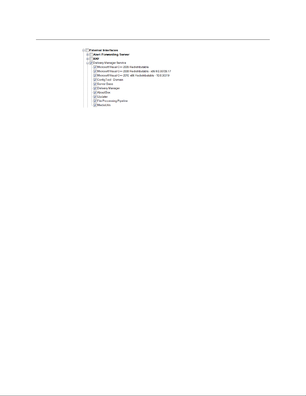
3From the Sel
4Check Deliv
checked.
ect Software menu, expand External Interface.
ery Manager. By default, all the required components will also be
tup.exe that is contained within the iTX 2.x Suite folder.
dministrator.
tion Window appears in front of the
lect
11
Page 18
Installing Delivery Manager
What’s next?
5Expand Workflow.
6Check W
This will install the Workflow Service, which is required for Delivery Manager to
function correctly.
7Click OK.
8 On the main installation splash screen, you will see Deliv
list of components you are installing. Click Continue.
The Delivery Manager installation will start.
orkflow Server.
ery Manager added to the
The installer guides you through the installation st
iTX Domain and the means by which the service communicates with the rest of the iTX
Framework Services. For more information on installing iTX, see the iTX System
Administrator Guide.
Delivery Manager is installed to the standard iTX location of
2.0\Services
What’s next?
Once Installation has completed, you need to perform the following tasks in order to use
Delivery Manager:
1 Create a configuration profile.
2 Add and configure your required endpoints. See the following chapters for more
3 Configure the Server Controller to run the Delivery Manager service. This may also
eps, including providing details of the
.
See Configuration Profiles and Endpoint Tabs, on
inf
ormation:
• Adding a CIFS Endpoint, on page 21.
• Adding an FTP Endpoint, on
page 24.
• Adding a Pitch Blue Endpoint, on page 26.
• Adding a DIVA Endpoint, on
page 27.
• Adding MassTech Endpoints, on page 32.
• Adding a PathFire Endpoint, on page 34.
• Adding Ardome Endpoints, on page 36.
• Adding FlashNet Endpoints, on
• Adding Core Endpoints, o
include configuring a
resilience model.
page 37.
n page 39.
C:\Program Files\iTX
page 15.
12
Page 19

Delivery Manager
Configuration and Setup Guide
See Configuring the Server Controller, on page 51 and Setting Up Delivery Manager
Resilience, on page 55.
4 Set up your required resilience model.
See Setting Up Delivery Manager Resilience on page 55.
5 Finalize your Delivery Manager system by installing and configuring any additional
systems and services that are required.
See Finalizing the Delivery Manager System, on page 59.
13
Page 20

Installing Delivery Manager
What’s next?
14
Page 21

Configuration Profiles and Endpoint Tabs
Although Delivery Manager provides a blank Default configuration profile on first
installation, it is recommended that you create named profile, as this provides more control
should you need to change endpoints or set up either of the resilience models.
This chapter explains how to create a configuration profile, the basic steps for adding an
endpoint, an overview of the endpoint tab and how to remove a configuration profile.
Summary
Creating a New Configuration Profile . . . . . . . . . . . . . . . . . . . . . . . . . . . . . . . . . . . . . . . . . . . . . . . . . 15
Basic Steps for Adding an Endpoint . . . . . . . . . . . . . . . . . . . . . . . . . . . . . . . . . . . . . . . . . . . . . . . . . . . 15
About Endpoint Configuration Tabs . . . . . . . . . . . . . . . . . . . . . . . . . . . . . . . . . . . . . . . . . . . . . . . . . . 17
Removing a Configuration Profile . . . . . . . . . . . . . . . . . . . . . . . . . . . . . . . . . . . . . . . . . . . . . . . . . . . . 19
Creating a New Configuration Profile
To create a new, named configuration profile:
1 From Windows, click START > All Programs > iTX 2.0 > Delivery Manager Config. The
Select Configuration dialog is displayed.
2 In a blank area of the Select Configuration dialog, right-click and select Add new
configuration from the context menu.
3 A dialog appears with a prompt for the new configuration name. The name you enter
will also be used to identify the corresponding instance in Server Controller Config,
e.g. “CIFS Search” for a CIFS endpoint configured in Search Media mode.
4Click OK to confirm your selection. The new named configuration profile appears in the
Select Configuration list.
5 Add endpoint tabs to store the configuration for each endpoint you required. For more
information see
Basic Steps for Adding an Endpoint, on page 15.
Basic Steps for Adding an Endpoint
To add a new endpoint to a Delivery Manager configuration profile:
1In the Select Configuration window, select a configuration profile and click OK. A blank
endpoint tab appears.
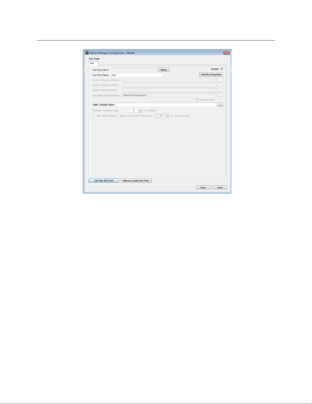
2 On the blank endpoint dialog, click Add new Endpoint. A blank “new” endpoint tab
appears.
15
Page 22
Configuration Profiles and Endpoint Tabs
Basic Steps for Adding an Endpoint
3Click the Select button next to the Endpoint Driver field. The Select Delivery Manager
Driver dialog appears.
4 Select an endpoint driver and click OK.
5In the En
dpoint Name field, enter the name to be used as a reference in the iTX
database.
6 Complete the dialog boxes that appear for the selected endpoint driver.
For information on the properties that are common to most of the endpoints, see
Generic Endpoint Configuration Settings, on page 17.
Specific instructions for each endpoint type can be found on the following pages:
• Adding a CIFS Endpoint, on page 21.
• Adding an FTP Endpoint, on
page 24.
• Adding a Pitch Blue Endpoint, on page 26.
• Adding a DIVA Endpoint, on
page 27.
• Adding MassTech Endpoints, on page 32.
• Adding a PathFire Endpoint, on page 34.
• Adding Ardome Endpoints, on page 36.
• Adding FlashNet Endpoints, on
• Adding Core Endpoints, o
7 If you wish to add another endpoint, click Ad
Another “new” tab appears. Follow step 2 to step 6 on
page 37.
n page 39.
d New Endpoint.
page 16 to configure each new
endpoint.
8Click S
ave then Close.
16
Page 23
9 Restart the Delivery Manager service. See Restarting an iTX Service on page 53 for
more information.
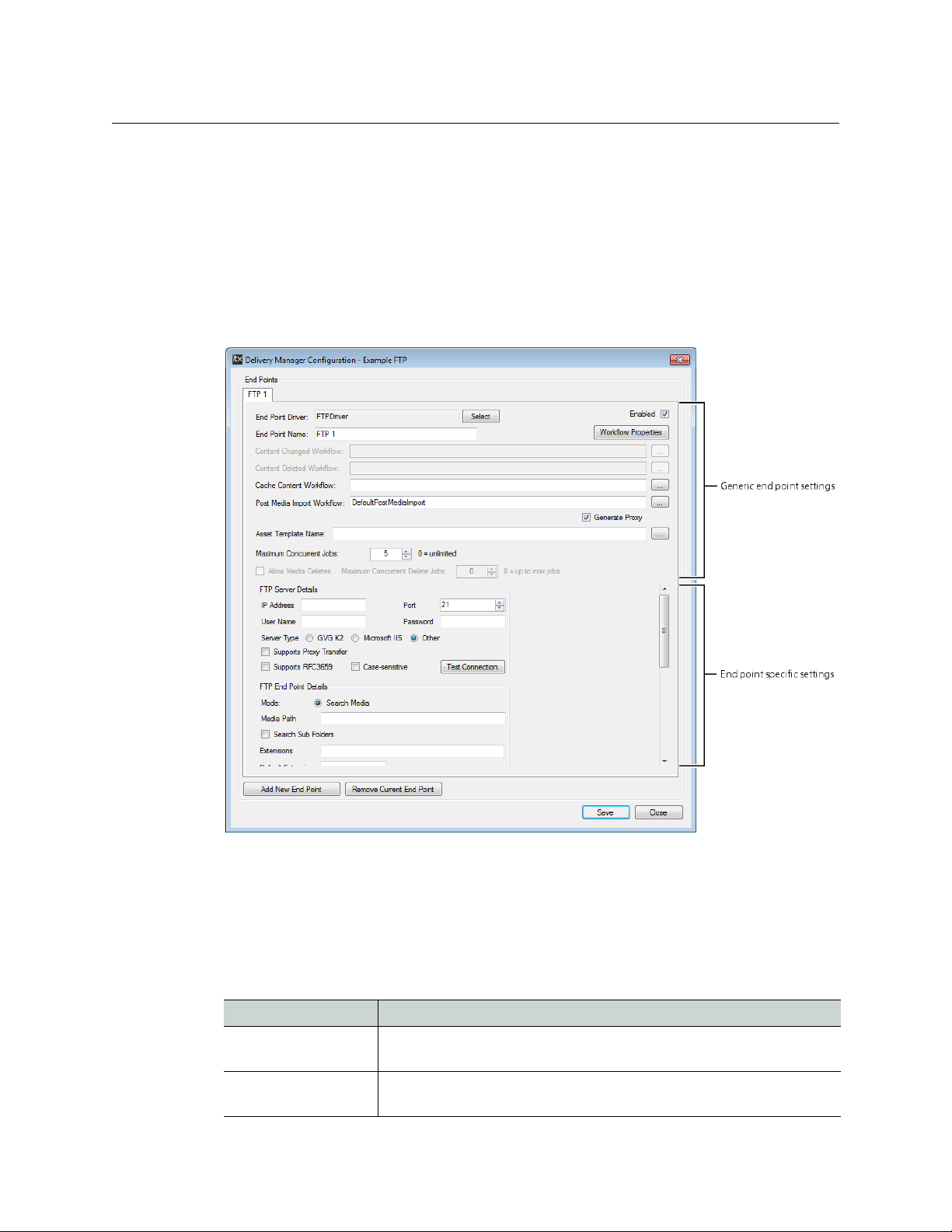
About Endpoint Configuration Tabs
When a driver for an endpoint is selected, the corresponding configuration options are
displayed. Certain generic options are shared by all of the endpoints types, but each
endpoint also has its own options. The image below shows the interface for an FTP
endpoint.
Delivery Manager
Configuration and Setup Guide
The specific endpoint configuration options are described in each endpoint’s chapter.
Generic Endpoint Configuration Settings
The following configuration options are common to all endpoints and can be configured in
different ways. Therefore the following guidelines should be considered when adding and
configuring endpoints.
Setting Description
Content Changed
rkflow
Wo
Content Deleted
rkflow
Wo
Click the browse button, then select the workflow to be used when a
new asset is discovered. Click
Click the browse button, then select the workflow to be used when an
asset is deleted. Click
OK to confirm you choice.
OK to confirm you choice.
17
Page 24

Configuration Profiles and Endpoint Tabs
Generic Endpoint Configuration Settings
Setting Description
Cache Content
Workflow
Post Media Import
Workflow
Generate Proxy This checkbox is only available when the Post Media Import
Asset Template Name Click the browse button, then select an iTX media asset template, so
Max Concurrent Jobs Enter a value for the total number of jobs that are allowed to run
Allow Media Deletes Check this option if you want the endpoint driver to process and act
Maximum Concurrent
Delete Jobs
Keep Media Location This option appears within the configuration options for certain
Test Co nnection If available, click this button to connect to the endpoint using the
Click the browse button, then select the workflow used to move media
and assets from the monitored endpoint to the iTX store (which may
trigger other jobs also). Click
The Post Media Import is an optional setting. See Post Media Import
Workflows, on page 6 for more information.
Workflow
versions of the media (e.g. smooth stream or MP4) will be generated
on import.
that all of the clips are registered with the same characteristics. Click
OK to confirm your choice.
For more information on creating asset templates see the iTX System
Administration Guide.
simultaneously from the endpoint. The default is 5. A value of 0 is
equal to unlimited.
upon delete requests.
When an endpoint is operating in Content Change mode and is
monitoring a network repository where media is placed temporarily
(i.e. just for iTX to ingest) it is recommended that this option is
checked. This means that once new media has been processed and
ingested, the copy deposited in the Content Change folder is actively
deleted by iTX.
However, if an endpoint is running in Content Change mode but is
monitoring a permanent network store, such as a NAS, then the option
should be unchecked to prevent accidental deletion of media being
added to the storage.
Checking this option also makes the Maximum Concurrent Delete
Jobs
This setting is only available if Allow Media Deletes is checked. The
maximum number of concurrent delete jobs you can set is 5.
endpoint types.
If you are exporting media or sending it an archive that is external to
iTX, you should consider checking this option. When checked, the iTX
database knows where the media has been moved to. Retrieving and
restoring the media to iTX is then a quicker process, as Delivery
Manager does not need to request all endpoints to search their stores
or archives when trying to find this asset.
current settings. This will confirm if the endpoint is correctly
configured.
is field is available. When checked, low resolution proxy
option appear.
OK to confirm you choice. .
18
Page 25
Removing a Configuration Profile
If you have created additional configuration profiles they can be removed from the Delivery
Manager Config. However, once
restored.
Note: You cannot remove the Default configuration profile. If you no
longer require the Default configuration profile, you can remove all of the
endpoints configured within it. If a Delivery Manager service attempts to
use a blank configuration profile, the service will fail to start.
To remove a Delivery Manager configuration,
1 From Windows, click ST
Select Configuration dialog appears, listing all of the existing configuration profiles.
2In the S
3 Right click on the selected configuration profile and choose Remove Configuration.
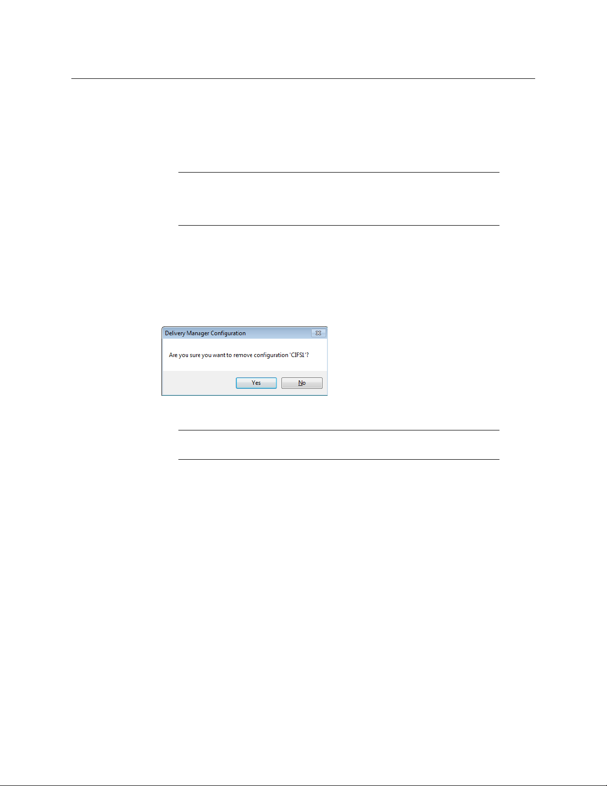
4 A dialog appears asking you to confirm the removal.
elect Configuration dialog, click on a configuration profile name to select it.
a configuration profile has been removed it cannot be
ART > All Programs > iTX 2.0 > Delivery Manager Config. The
Delivery Manager
Configuration and Setup Guide
5Click Ye s.
Note: If you only want to remove a single endpoint, open the configuration
profile, select the endpoint table and click
Remove Current Endpoint.
19
Page 26

Configuration Profiles and Endpoint Tabs
Removing a Configuration Profile
20
Page 27

Adding Network Share Endpoints
This chapter explains the prerequisites and configuration steps required to add any of the
supported network share endpoints.
Summary
Adding a CIFS Endpoint . . . . . . . . . . . . . . . . . . . . . . . . . . . . . . . . . . . . . . . . . . . . . . . . . . . . . . . . . . . . . . 21
Adding an FTP Endpoint . . . . . . . . . . . . . . . . . . . . . . . . . . . . . . . . . . . . . . . . . . . . . . . . . . . . . . . .
Adding a Pitch Blue Endpoint . . . . . . . . . . . . . . . . . . . . . . . . . . . . . . . . . . . . . . . . . . . . . . . . . . .
Adding a CIFS Endpoint
Configuring a CIFS Endpoint in Content Change (Drop Box) Mode
To add a CIFS endpoint in Content Change (Drop Box) mode:
1 Open an existing configuration profile or crea
tab, as described in step 1 and step 2 of Basic Steps for Adding an Endpoint, on
page 15.
2Click the Se
Driver dialog appears.
3 Select CIFS and
4In the En
database. For example, “
5 Click the browse button for the C
Changed’ Workflow... dialog appears.
6 Select the required workflow for performing drop box actions.
register an asset but not transfer the file.
DefaultContentChanged_RegisterAndImport.
7The Post Media Import Workflow field will be automatically populated with
DefaultPostMediaImport.
lect button next to the Endpoint Driver field. The Select Delivery Manager
click OK.
dpoint Name field, enter the name to be used as a reference in the iTX
CIFS Drop Box”.
ontent Changed Workflow field. The Select ‘Content
te a new one, then add a new endpoint
This workflow should
For example
. . . . . . 24
. . . . . . 26
Note: If you have not got the FPP Transcode Service installed, you will need
to delete this entry.
8 If you are using a Post Media Import Workflow, you can also generate low resolution
versions of clips as they are imported by checking the Generate Proxy checkbox.
9 Click the browse button for A
appears.
10 Select the required template, so that all of the clips are registered with the same
acteristics. Click OK.
char
sset Template Name. The Select Asset Template dialog
21
Page 28

Adding Network Share Endpoints
Configuring a CIFS Endpoint in Search Media Mode
11 Specify the Maximum Concurrent Jobs you want this endpoint to process.
12 Under CIFS Endpoint Details, select Drop Box.
13 In the Me
14 Complete the fields in the CI
Reference, on
15 Click S
dia Path field, enter the UNC path of the directory being monitored.
FS Endpoint Details, as described in CIFS Endpoint Details
page 23.
ave then Close.
16 Restart the Delivery Manager service. See Restarting an iTX Service on page 53 for
more information.
Configuring a CIFS Endpoint in Search Media Mode
To add a CIFS endpoint in Search Media mode:
1 Open an existing configuration profile or crea
tab, as described in step 1 and step 2 of Basic Steps for Adding an Endpoint, on
page 15.
2Click the Se
lect button next to the Endpoint Driver field. The Select Delivery Manager
Driver dialog appears.
3 Select CIFS and
4In the En
dpoint Name field, enter the name to be used as a reference in the iTX
database. For example, “
5 Click the browse button for the C
click OK.
CIFS Search Media”.
ache Content Workflow field. The Select ‘Cache
Media’ Workflow... dialog appears.
6 Select the required workflow for moving media and assets to the iTX store. For
DefaultCacheMedia.
le
examp
7The Po
st Media Import Workflow field will be automatically populated with
DefaultPostMediaImport.
te a new one, then add a new endpoint
22
Note: If you have not got the FPP Transcode Service installed, you will need
to delete this entry.
8 If you are using a Post Media Import Workflow, you can also generate low resolution
versions of clips as they are imported by checking the Generate Proxy checkbox.
9 Click the browse button for A
sset Template Name. The Select Asset Template dialog
appears.
10 Select the required template, so that all of the clips are registered with the same
acteristics. Click OK.
char
11 Specify the Max
12 If required, check A
imum Concurrent Jobs you want this endpoint to process.
llow Media Deletes, then Specify the Maximum Concurrent Delete
Jobs you want this endpoint to process.
13 Under CIFS Endpoin
14 In the Me
dia Path field, enter the UNC path of the directory being monitored.
15 Complete the fields in the CI
Reference, on
16 Click S
ave then Close.
t Details, select Search Media.
FS Endpoint Details, as described in CIFS Endpoint Details
page 23.
Page 29

17 Restart the Delivery Manager service. See Restarting an iTX Service on page 53 for
more information.
18 To use a CIFS endpoint in Search Media mode, you must also complete the steps
described in
Additional Setup for Search Media mode, on page 59.
Adding a CIFS Endpoint in Manual Mode
To add a CIFS endpoint in manual (Export) mode:
1 Open an existing configuration profile or create a new one, then add a new endpoint
tab, as described in
page 15.
2Click the Select button next to the Endpoint Driver field. The Select Delivery Manager
Driver dialog appears.
3 Select CIFS and click OK.
4In the Endpoint Name field, enter the name to be used as a reference in the iTX
database. For example, “
5 Click the browse button for Asset Template Name. The Select Asset Template dialog
appears.
6 Select the required template, so that all of the clips are registered with the same
characteristics. Click OK.
7 Specify the Maximum Concurrent Jobs you want this endpoint to process.
8Under CIFS Endpoint Details, select Export.
9In the Media Path field, enter the UNC path of the directory being monitored.
10 Complete the fields in the CIFS Endpoint Details, as described in CIFS Endpoint Details
Reference, on page 23.
11 Click Save then Close.
12 Restart the Delivery Manager service. See Restarting an iTX Service on page 53 for
more information.
13 To use a CIFS endpoint in manual mode, you must also complete the steps described in
Additional Setup for Manual/Export Mode, on page 61.
step 1 and step 2 of Basic Steps for Adding an Endpoint, on
CIFS Export”.
Delivery Manager
Configuration and Setup Guide
CIFS Endpoint Details Reference
The table below describes the additional configuration options contained within the CIFS
Endpoint Details section of a CIFS endpoint.
Setting Description
Mode CIFS endpoints can operate in Drop Box (Content Changed) Mode,
Search Media mode or Export Mode.
Media Path The UNC path of the directory being monitored.
Search Sub Folders
(on/off)
The endpoint driver searches any folders contained within the
designated media folder.
23
Page 30

Adding Network Share Endpoints
Adding an FTP Endpoint
Setting Description
File Extensions
Default Extension If restoring files that have no file extension from an external archive,
Exclude Folders
Keep Media Location
Remove File
Extension on Archive
List of file extensions to be processed. If you want all file types to be
processed, leave this field blank.
the extension entered here will be added to each file name when
they are transferred into iTX.
Using add/remove buttons you can add details of sub folders you wish
to exclude.
This is a search string, so the folders need to be typed in the dialog like
this:
*\folder name\*
When using CIFS endpoints with Omneon essence based media, add
media.dir to the list of excluded folders to prevent Delivery Manager
viewing components from essence based media files as individual
assets.
This option instructs the database to keep the original location of the
media as part of the asset record (if the file is being copied rather than
transferred).
Some archives and media stores do not support DOS file extensions,
because they only support one file type, meaning the extension is
not required.
This endpoint option removes the file extension from the file name
when it is moved to an archive.
Maximum Transfer
Bitrate
Adding an FTP Endpoint
FTP endpoints can be configured as generic FTP endpoints, a Grass Valley K2 or a PitchBlue
endpoint. They work in the same as any standard FTP client, such as FileZilla. Therefore, the
FTP endpoint's configuration options reflect standard FTP requirements and settings.
FTP endpoints only operate in Search Media Mode.
To add an FT P end poin t :
1 Open an existing configuration profile or create a new one, then add a new endpoint
tab, as described in
page 15.
2Click the Select button next to the Endpoint Driver field. The Select Delivery Manager
Driver dialog appears.
3 Select FTPDriver and click OK.
4In the Endpoint Name field, enter the name to be used as a reference in the iTX
database. For example, “
5 Click the browse button for the Cache Content Workflow field. The Select ‘Cache
Media’ Workflow... dialog appears.
This slider sets the throttle rate on network file transfer speeds for
each file. The default is 100mbs.
step 1 and step 2 of Basic Steps for Adding an Endpoint, on
FTP K2”.
24
Page 31

Delivery Manager
Configuration and Setup Guide
6 Select the required workflow for performing Content Change actions. For example
DefaultCacheMedia.
7The Po
st Media Import Workflow field will be automatically populated with
DefaultPostMediaImport.
Note: If you have not got the FPP Transcode Service installed, you will need
to delete this entry.
8 If you are using a Post Media Import Workflow, you can also generate low resolution
versions of clips as they are imported by checking the Generate Proxy checkbox.
9 Click the browse button for A
sset Template Name. The Select Asset Template dialog
appears.
10 Select the required template, so that all of the clips are registered with the same
acteristics. Click OK.
char
11 Specify the Max
imum Concurrent Jobs you want this endpoint to process.
12 If required, check Allow Media Deletes, then Specify the Maximum Concurrent Delete
Jobs you want this endpoint to process.
13 In the FTP S
erver Details section, complete the following fields:
Setting Description
IP Address The IP Address of the FTP Server
Port TCP/IP Port used by the FTP Server (usually 20 or 21)
Username The username required to access the FTP folder
Password The password required to access the FTP folder
Server Type Select the type of FTP server you are connecting to. The options are:
•GVG K2
• Microsoft IIS
•Other
Supports Proxy
Transfer
Supports RFC3659 RFC3659 is an extension to the standard set of FTP commands that
Support FTP Proxy Server transfers from an FTP Server. (Note: server
to server FTP requires FTP access to the iTX Store). Disabling this
option forces the transfer to be pulled from the external FTP through
Delivery Manager
includes the
use of character sets other than US-ASCII
14 In the FTP Endpoint Details section, complete the following fields, as required:
Setting Description
Search Media only) FTP endpoints can only operate in Search Media mode.
Mode (
Media Path The UNC path of the directory being monitored.
Search Sub Fold
ers (on/off) The endpoint driver also searches any folders contained
within the designated media folder.
Extensions List of file extensions to be processed. If you want all file
types to be pr
ocessed, leave this field blank.
25
Page 32

Adding Network Share Endpoints
Adding a Pitch Blue Endpoint
Setting Description
Default Extension If restoring files from an external archive that have no file
Exclude Folders Using add/remove buttons you can add details of sub folders
Keep Media Location This option instructs the database to keep the original
Remove File Extension on
Archive
Maximum Transfer Bitrate This slider sets the throttle rate on network file transfer
extension, this is the default extension type is added to the
file name when transferred into iTX.
you wish to exclude. Note: this is a search string, so the
folders need to be typed using the syntax:
name\*
location of the media as part of the asset record (if the file is
being copied rather than transferred).
Some archive and media stores do not support DOS file
extensions. This is because they only support one file type,
meaning the extension is not required. This option removes
the file extension from the file name when moving to an
archive.
speeds for each file. The default is 100mbs.
.
*\folder
15 Click Save then Close.
16 Restart the Delivery Manager service. See Restarting an iTX Service on page 53 for
more information.
17 As FTP endpoints can only operate in Search Media mode, you must also complete the
steps described in
Additional Setup for Search Media mode, on page 59.
Adding a Pitch Blue Endpoint
Pitch Blue uses the standard FTP protocol, but requires a specific 'hard coded' username
and password, which needs to be entered into the configuration dialog of the Pitch Blue
archive itself. This is because the Pitch Blue archive delivery system uses a dedicated
proprietary computer for content delivery. The Username and Password FTP connection
details are supplied to you when your Pitch Blue System is installed. If you do not know
these details, contact your IT department.
26
Page 33

Adding 3rd Party Endpoints
This section explains the prerequisites and configuration steps required to add any of the
supported 3rd party endpoints.
Summary
Adding a DIVA Endpoint . . . . . . . . . . . . . . . . . . . . . . . . . . . . . . . . . . . . . . . . . . . . . . . . . . . . . . . . . . . . . . 27
Adding MassTech Endpoints . . . . . . . . . . . . . . . . . . . . . . . . . . . . . . . . . . . . . . . . . . . . . . . . . . . . . . . . . . 32
Adding a PathFire Endpoint . . . . . . . . . . . . . . . . . . . . . . . . . . . . . . . . . . . . . . . . . . . . . . . . . . . . . . . . . . 34
Adding Ardome Endpoints . . . . . . . . . . . . . . . . . . . . . . . . . . . . . . . . . . . . . . . . . . . . . . . . . . . . . . . . . . . 36
Adding FlashNet Endpoints . . . . . . . . . . . . . . . . . . . . . . . . . . . . . . . . . . . . . . . . . . . . . . . . . . . . . . . . . . . 37
Adding a DIVA Endpoint
Prerequisites for DIVA Endpoints in Manual Mode
Configure DIVA to restore media to iTX
When the DIVArchive is added to your iTX system for the first time, you need to add an entry to
the DIVA Manager with the location of the server to which Delivery Manager is asking it to restore
media.
To configure DIVA Manager with the location of the media store server:
1 On the DIVArchive server, open the Configuration Utility.
2In the Sources and Destinations section, click the + in the top right corner. The Edit
Row window appears.
3In the Source Name field, enter Store name from Opus. The case must match the case
of the Store name in Opus Store Management.
4 In the Root Path field, enter the location of the folder on the media store DIVA should use
to restore media.
27
Page 34

Adding 3rd Party Endpoints
Prerequisites for DIVA Endpoints in Manual Mode
5Click OK. The Edit Row window closes.
6On the C
onfiguration Utility, click Update to apply the changes.
Configure DIVA to archive media
For archive requests, you will also need to create an entry in DIVA Manager with the host name
of the Opus store.
To configure DIVA Manager for archive requests:
1 On the DIVArchive server, open the C
2In the S
ources and Destinations section, click the + in the top right corner. The Edit
onfiguration Utility.
Row window appears.
3In the Sour
entered in all capital letters (e.g.
ce Name field, enter host name of the Opus store. The name must be
ISILON01.PLAYOUT.COM).
4 In the Root Path field, enter the location of the folder on the Opus store for media archive.
28
5Click OK. The Edit Row window closes.
6On the Configuration Utility, click Update to apply the changes.
Page 35

Delivery Manager
Configuration and Setup Guide
Configure the default Opus store
Delivery Manager requests that the media be restored to the Opus Admin Default Store, so if you
are adding multiple stores to DIVA, the Opus Admin Default must be one of the stores you add.
Note: Delivery Manager's endpoint passes a restore request to DIVA using
the default store name, so the
Store field in Opus.
in the
You configure which store is the default store for Opus to use via the iTX Desktop's
Engineering layout.
To configure the default Opus store from the Engineering layout:
1 Open the iTX Desktop Client and select the Eng
2In the Syst
3In the St
em Admin section, click Opus Admin.
ore Management section, select the store from the Store drop down dialog:
Source Name in DIVA must match the name
ineering layout.
4Check Default Store.
5 On the Opus Admin window, click Sa
ve, then Close.
Configure DIVA for partial restores
Because the DIVArchive Manager software can only read embedded time codes (such as time of
day or feeds recorded with a start time o f 10:00:00:00) from some file formats, a configuration file
PartialRestore.conf) found in the DIVA Actor directory must be edited to instruct
(called
DIVA to ignore the original time codes associated with the asset and calculate the Co-reference
clip in and out points as if they start from 0.
Note: This is currently restricted to Quicktime MOV file formats, both self-
contained and referenced based types.
29
Page 36

Adding 3rd Party Endpoints
Configuring a DIVA Endpoint
To edit the partial restore configuration file:
1 In Windows Explorer, navigate to:
C:\<DIVA install folder>\Program\Actor\conf\actor
Note: The Diva install folder can be named anything as part of the DIVA
Manager install process.
2Open the file
3 Locate the parameter
PartialRestore.conf in a text editor, such as Windows Notepad.
XXX_IGNORE_START_TIMECODE (where XXX is the media format
extension type).
4 To enable 0 based time code calculations f
or Co-Reference clip generation, set this
value to '1' for each media type you have archived on DIVA.
For example, for a QuickTime file, locate and edit
that it reads
QT_IGNORE_START_TIMECODE=1
QT_IGNORE_START_TIMECODE=01 so
5 Once all of the required entries have been modified, the edited section of the file will
look like this (where the modified lines are in italics):
# If the parameter XXX_IGNORE_START_TIMECODE is set to 1, partial
restore
# will ignore the SOM value of the original clip and process TCIN and
UT as if
TCO
# it starts from 00:00:00:00.
# Default value is 0
##################################################
# QuickTime specific options
##################################################
QT_IGNORE_START_TIMECODE=1
##################################################
# Avi specific options
##################################################
AVI_IGNORE_START_TIMECODE=1
##################################################
# EVS MXF specific options
##################################################
EVS_MXF_IGNORE_START_TIMECODE=1
6 Save and close the PartialRestore.conf file.
Configuring a DIVA Endpoint
DIVArchive endpoints are able to operate in Content Change, Search Media and manual
modes, depending on whether or not certain workflows are selected during the
configuration.
IMPORTANT
You should not attempt to operate a single endpoint configuration in more
than one mode. For example, if you are using the DIVArchive in Content
Change mode you should select a
select a
30
Cache Content Workflow within the same configuration profile.
Content Changed Workflow and not
Page 37

Delivery Manager
Configuration and Setup Guide
To add a DIVA endpoint:
1 Open an existing configuration profile or crea
te a new one, then add a new endpoint
tab, as described in step 1 and step 2 of Basic Steps for Adding an Endpoint, on
page 15.
2Click the Se
lect button next to the Endpoint Driver field. The Select Delivery Manager
Driver dialog appears.
3 Select Div
4In the En
aDriver and click OK.
dpoint Name field, the name you enter must match the corresponding DIVA
category name.
5 If you are operating a DIVArchive in manual mode, none
of the workflow fields need to
be populated.
6 If you are operating a DIVArchive in C
a Click the browse button for the C
ontent Change mode:
ontent Changed Workflow field. The Select
‘Content Changed’ Workflow... dialog appears.
b Select the required workflow for moving
example
DefaultContentChanged_RegisterOnly.
7 If you are operating a DIVArchive in S
earch Media mode:
media and assets to the iTX store. For
a Click the browse button for the Cache Content Workflow field. The Select ‘Cache
Media’ Workflow... dialog appears.
b Select the required workflow for moving
example
DefaultCacheMedia.
media and assets to the iTX store. For
8 If you want the endpoint to manage asset deletions, click the browse button for
C
ontent Deleted Workflow and select the required workflow. For example
DefaultDivaDelete_RemoveLocation.
9The Po
st Media Import Workflow field will be automatically populated with
DefaultPostMediaImport.
Note: If you have not got the FPP Transcode Service installed, you will need
to delete this entry.
10 If you are using a Post Media Import Workflow, you can also generate low resolution
versions of clips as they are imported by checking the Generate Proxy checkbox.
11 Click the browse button for A
sset Template Name. The Select Asset Template dialog
appears.
12 Select the required template, so that all of the clips are registered with the same
char
acteristics. Click OK.
13 Specify the Max
14 If required, check A
imum Concurrent Jobs you want this endpoint to process.
llow Media Deletes, then Specify the Maximum Concurrent Delete
Jobs you want this endpoint to process.
31
Page 38

Adding 3rd Party Endpoints
Adding MassTech Endpoints
15 In the Diva Archive Configuration section, complete the following as required:
Setting Description
Allow Overwriting
hive
Arc
Monitor DIVA for
Changes
When moving an asset to the archive, this checkbox allows
overwriting of an asset if it already exists on the DIVA.
If not enabled then archive jobs will fail if the object already exists
on the DIV
If this checkbox is enabled, the endpoint regularly checks the DIVA
for objects in the category of that endpoint that have been
created, modified, or deleted and update iTX accordingly.
A in the category of the endpoint.
The status of the connection to the DIVA of each endpoint is
checked every 30 seconds. If the connection is lost, the health
indicator turns red for the endpoint on the Delivery Manager
Service.
It automatically tries to reconnect to the DIVA. If the
onnection is re-established, the status light returns to green.
c
Max Concurrent
Jobs
Manager IP
The highest number of jobs that are allowed to run
simultaneously from that endpoint.
The IP address of the DIVArchive Manager Server.
Address
Port
The TCP/IP Port that the endpoint communicates with the
archive on.
16 Click Save then Close.
17 Restart the Delivery Manager service. See Restarting an iTX Service on page 53 for
more information.
18 Finalize the Delivery Manager setup:
• To use a DIVA endpoint in Search Media mode, you must also complete the steps
scribed in Additional Setup for Search Media mode, o
de
• To use a DIVA endpoint in manual mode
, you must also complete the steps
n page 59.
described in Additional Setup for Manual/Export Mode, on page 61.
Adding MassTech Endpoints
MassTech endpoints are able to operate in Content Change and Search Media, depending
on whether or not certain workflows are selected during the configuration.
IMPORTANT
You should not attempt to operate a single endpoint configuration in more
than one mode. For example, if you are using the MassTech archive in
Content Change mode you should select a
and not select a Cache Content Workflow within the same configuration
profile.
32
Content Changed Workflow
Page 39

Delivery Manager
Configuration and Setup Guide
To add a MassTec h end p oint :
1 Open an existing configuration profile or crea
te a new one, then add a new endpoint
tab, as described in step 1 and step 2 of Basic Steps for Adding an Endpoint, on
page 15.
2Click the Se
lect button next to the Endpoint Driver field. The Select Delivery Manager
Driver dialog appears.
3 Select Ma
4In the En
database. For example, “
5 If you are operating a MassTech archive in C
a Click the browse button for the C
ssTech and click OK.
dpoint Name field, enter the name to be used as a reference in the iTX
MassTech Archive”.
ontent Change mode:
ontent Changed Workflow field. The Select
‘Content Changed’ Workflow... dialog appears.
b Select the required workflow for moving
workflow should register an asset but not transfer the file.
DefaultContentChanged_RegisterOnly.
6 If you are operating a MassTech archive in S
a Click the browse button for the C
ache Content Workflow field. The Select ‘Cache
media and assets to the iTX store. This
For example,
earch Media mode:
Media’ Workflow... dialog appears.
b Select the required workflow for moving
example,
DefaultCacheMedia.
media and assets to the iTX store. For
7 If you want the endpoint to manage asset deletions, click the browse button for
Content Deleted Workflow and select the required workflow.
8The Po
st Media Import Workflow field will be automatically populated with
DefaultPostMediaImport.
Note: If you have not got the FPP Transcode Service installed, you will need
to delete this entry.
9 If you are using a Post Media Import Workflow, you can also generate low resolution
versions of clips as they are imported by checking the Generate Proxy checkbox.
10 Click the browse button for A
sset Template Name. The Select Asset Template dialog
appears.
11 Select the required template, so that all of the clips are registered with the same
acteristics. Click OK.
char
12 Specify the Max
13 If required, check A
imum Concurrent Jobs you want this endpoint to process.
llow Media Deletes, then Specify the Maximum Concurrent Delete
Jobs you want this endpoint to process.
33
Page 40

Adding 3rd Party Endpoints
Adding a PathFire Endpoint
14 In the MassTech Archive Configuration section, complete the following fields:
Setting Description
Manager IP address The IP address of MassTech.
Username/Password
This information is usually supplied by MassTech.
Note: Only one connection at a time can be made using a
single account, so the endpoint may not be able to connect if
something else is already using it.
MassTech ID of Store
for iTX Media
Allow Media Deletes This option should be enabled if you wish to be able to delete
Timeout (minutes) This defaults to 60. If a job has not progressed at all in this time
Allow Overwriting
Archive
Monitor MassTech
for Changes
This is the Server ID configured in the MassTech for the iTX
media server from which media is archived and to which media
is restored. This has to be configured by MassTech.
any media assets from MassTech.
frame it will be cancelled.
Leave this option disabled for normal operations.
Leave this option disabled for normal operations.
15 Click Save then Close.
16 Restart the Delivery Manager service. See Restarting an iTX Service on page 53 for
more information.
17 Finalize the Delivery Manager setup:
• To use a MassTech endpoint in Search Media mode, you must also complete the
described in Additional Setup for Search Media mode, on
steps
• To use a MassTech endpoint in manual mode
, you must also complete the steps
page 59.
described in Additional Setup for Manual/Export Mode, on page 61.
Adding a PathFire Endpoint
PathFire endpoints only operate in Search Media Mode.
Prerequisites for PathFire Endpoints
If you are running Windows Server 2008 R2 or Windows Server 2012 you will also need to
install Windows Message Queuing in order for the PathFire Service to run correctly.
To install Message Queuing on Windows Server 2008 R2 and Windows Server 2012:
34
1 From Windows, click Star
Server Manager application opens.
2Click Ad
d Features.
t > Programs > Administrative Tools > Server Manager. The
Page 41

3Expand MSMQ > MSMQ Services, and then check the checkboxes for the Message
Queuing features that you want to install.
4Click Ne
xt, then click Install.
5 If you are prompted to restart the computer, click OK
Configuring a PathFire Endpoint
To add an PathFire endpoint:
1 Open an existing configuration profile or crea
tab, as described in step 1 and step 2 of Basic Steps for Adding an Endpoint, on
page 15.
2Click the Se
Driver dialog appears.
3 Select Pa
4In the En
database. For example, “
5 Click the browse button for the C
Media’ Workflow... dialog appears.
6 Select the required workflow for performing Content Change actions. For example,
DefaultCacheMedia.
7The Po
DefaultPostMediaImport.
lect button next to the Endpoint Driver field. The Select Delivery Manager
thFireDriver and click OK.
dpoint Name field, enter the name to be used as a reference in the iTX
st Media Import Workflow field will be automatically populated with
Delivery Manager
Configuration and Setup Guide
to complete the installation.
te a new one, then add a new endpoint
PathFire”.
ache Content Workflow field. The Select ‘Cache
Note: If you have not got the FPP Transcode Service installed, you will need
to delete this entry.
8 If you are using a Post Media Import Workflow, you can also generate low resolution
versions of clips as they are imported by checking the Generate Proxy checkbox.
9 Click the browse button for A
sset Template Name. The Select Asset Template dialog
appears.
10 Select the required template, so that all of the clips are registered with the same
acteristics. Click OK.
char
11 Complete the remaining fie
lds, as described below:
Setting Descriptions
Maximum Concurrent Jobs Enter the maximum number of jobs you want this
endpoint to process simultaneously. The default is 5.
Use PathFore Format Sheet Check this checkbox to use the format sheet included
with PathFire content.
IP Address Enter the IP Address of the PathFire source server.
Media path Enter the UNC path of the shared delivery location on
your NAS as defined in PathFire’s configuration.
35
Page 42

Adding 3rd Party Endpoints
Adding Ardome Endpoints
Setting Descriptions
HD Location Enter the HD location alias defined in PathFire that
SD Location Enter the SD location alias defined in PathFire that
PathFire Timeout (minutes) Enter the duration in minutes for the PathFire server’s
12 Click Save then Close.
13 Restart the Delivery Manager service. See Restarting an iTX Service on page 53 for
more information.
14 To use a PathFire endpoint in Search Media mode, you must also complete the steps
scribed in Additional Setup for Search Media mode, o
de
PathFire source to Missing Materials Manager.
represents the Media Path above.
Note: This field should be used in conjunction with an
asset template for HD media.
represents the Media Path above.
Note: This field should be used in conjunction with an
asset template for SD media.
time out. The default is 60 minutes.
n page 59 and also add the
Adding Ardome Endpoints
To add an Ardome endpoint:
1 Open an existing configuration profile or crea
tab, as described in step 1 and step 2 of Basic Steps for Adding an Endpoint, on
page 15.
2Click the Se
Driver dialog appears.
3 Select Ar
4In the En
database. For example, “
5 Click the browse button for the C
Media’ Workflow... dialog appears.
6 Select the required workflow for performing Content Change actions. For example
DefaultCacheMedia.
7The Po
DefaultPostMediaImport.
8 If you are using a Post Media Import Workflow, you can also generate low resolution
versions of clips as they are imported by checking the Generate Proxy checkbox.
lect button next to the Endpoint Driver field. The Select Delivery Manager
dome and click OK.
dpoint Name field, enter the name to be used as a reference in the iTX
st Media Import Workflow field will be automatically populated with
Note: If you have not got the FPP Transcode Service installed, you will need
to delete this entry.
te a new one, then add a new endpoint
Ardome Archive”.
ache Content Workflow field. The Select ‘Cache
36
Page 43

Delivery Manager
Configuration and Setup Guide
9 Click the browse button for Asset Template Name. The Select Asset Template dialog
appears.
10 Select the required template, so that all of the clips are registered with the same
acteristics. Click OK.
char
11 Specify the Max
12 In the Ardome Configuration section, complete the following fields:
Setting Description
IP Address Enter the IP address of the Ardome server
User Name Enter the user name, as configured in the Ardome system and provided
Password Enter the password as configured in the Ardome system and provided
Transfer Service Enter the name of the transfer service as configured on the Ardome by
imum Concurrent Jobs you want this endpoint to process.
by a system administrator
by a system administrator
the Ardome system administrator.
The Ardome transfer Service is where you configure the iTX store
l
ocation where you wish the de-archived media to be transferred to.
13 Click Save then Close.
14 Restart the Delivery Manager service. See R
more information.
15 To use an Ardome endpoint in Search Media mode, you must also complete the steps
scribed in Additional Setup for Search Media mode, o
de
estarting an iTX Service on page 53 for
Adding FlashNet Endpoints
Prerequisites for FlashNet Endpoints in Manual Mode
In order to use a FlashNet Archive with Delivery Manager, the following prerequisites must
be met:
• The FlashNet Archive must be running v
• The FlashNet services must be logged on as a user with read/write access to the ITX
NAS.
Configuring a FlashNet Endpoint
To add a FlashNet endpoint:
1 Open an existing configuration profile or crea
tab, as described in step 1 and step 2 of Basic Steps for Adding an Endpoint, on
page 15.
2Click the Se
Driver dialog appears.
3 Select F
lect button next to the Endpoint Driver field. The Select Delivery Manager
lashNet and click OK.
ersion 6.4.13.003.
te a new one, then add a new endpoint
n page 59.
37
Page 44

Adding 3rd Party Endpoints
Configuring a FlashNet Endpoint
4In the Endpoint Name field, enter the name to be used as a reference in the iTX
database. For example, “
5 Click the browse button for the C
Media’ Workflow... dialog appears.
6 Select the required workflow for moving media and assets to the iTX store. For
examp
7The Post Media Import Workflow field will be automatically populated with
DefaultPostMediaImport.
Note: If you have not got the FPP Transcode Service installed, you will need
to delete this entry.
8 If you are using a Post Media Import Workflow, you can also generate low resolution
versions of clips as they are imported by checking the Generate Proxy checkbox.
9 Click the browse button for A
appears.
10 Select the required template, so that all of the clips are registered with the same
acteristics. Click OK.
char
11 Specify the Max
12 If required, check A
Jobs you want this endpoint to process.
13 In the IP
14 In the Po
15 In the Default Volume Group field enter the default storage group on the FlashNet
Archive where the media is stored.
FlashNet Archive”.
ache Content Workflow field. The Select ‘Cache
DefaultCacheMedia.
le
sset Template Name. The Select Asset Template dialog
imum Concurrent Jobs you want this endpoint to process.
llow Media Deletes, then Specify the Maximum Concurrent Delete
address field, enter the IP address of the FlashNet Archive machine.
rt field enter 8199.
IMPORTANT
If a storage group exists on the FlashNet Archive with a name that
matches the content type of the asset being archived, media will be
archived to the this group instead of the default.
16 Check the following check boxes as required:
• Allow Overwrite
• Verify Archived Content
• Use FTP Accessor
17 If restoring files that have no file extension from an external archive, the extension
en
tered in Default Extension will be added to each file name when they are transferred
into iTX.
18 Click S
ave then Close.
19 Restart the Delivery Manager service. See Restarting an iTX Service on page 53 for
more information.
20 To use a FlashNet endpoint in Manual Mode, you must also complete the steps
scribed in Additional Setup for Manual/Export Mode, on page 61.
de
38
Page 45

This chapter is for customers who are in the process of migrating from either an iTX 1.4 or a
Colossus system (which are sometimes referred to as Core systems) to an iTX 2.x system. It
can also be used by customers who are running a Core system and an iTX 2.x system in
parallel.
Summary
About the Core Endpoint . . . . . . . . . . . . . . . . . . . . . . . . . . . . . . . . . . . . . . . . . . . . . . . . . . . . . . . . . . . . . 39
Preparing the Database for Core Endpoints . . . . . . . . . . . . . . . . . . . . . . . . . . . . . . . . . . . . . . . . . . . 40
Generic Steps for Adding a Core Endpoint . . . . . . . . . . . . . . . . . . . . . . . . . . . . . . . . . . . . . . . . . . . . . 42
Generic Steps for Adding a Core Endpoint . . . . . . . . . . . . . . . . . . . . . . . . . . . . . . . . . . . . . . . . . . . . . 42
Additional Configurations for Colossus Systems . . . . . . . . . . . . . . . . . . . . . . . . . . . . . . . . . . . . . . . 44
Additional Configurations for iTX 1.4 Systems . . . . . . . . . . . . . . . . . . . . . . . . . . . . . . . . . . . . . . . . . 47
Additional Configurations for Both Colossus and iTX 1.4 Systems . . . . . . . . . . . . . . . . . . . . . . 48
Configuring Omneon Video Servers and FTP Endpoints . . . . . . . . . . . . . . . . . . . . . . . . . . . . . . . 49
About the Core Endpoint
Adding Core Endpoints
The Core endpoint facilitates the movement of media and asset records from a
Colossus/iTX 1.4 system.
Because the iTX 2.x and Colossus/iTX 1.4 databases differ in structure, the Core endpoint
effectively acts as a translator between the two systems. It does not in itself handle the
transfer of any media or asset data. Transfers are passed to one of the other endpoints.
For example, if a schedule added to a channel in the new 2.x system requires a piece of
media, its metadata (duration in/out points etc.) from the Colossus/iTX 1.4 system are
imported directly by the Core endpoint while the retrieval of the actual media is passed to a
separate endpoint (e.g. a CIFS or FTP endpoint, configured to point at the Colossus/iTX 1.4
system's relevant storage location).
Just like the other endpoints, the Core endpoint can operate in either Content Change
mode or Search Media mode. The endpoint connects to a Colossus/iTX 1.4 Database and
creates or modifies asset records in iTX 2.x when either:
• Assets are created or modified in the Colossus/iTX 1.4 system.
• Assets are requested by iTX as they are required in a future schedule.
39
Page 46

Adding Core Endpoints
Core Endpoint Asset Deletion
When a Core endpoint is used in conjunction with one of the other endpoints, media can
be transferred from the Colossus/1.4 System to the iTX 2.x system. This allows users to do
the following:
• Port all their of media and asset data ov
• Transfer media as and when files are needed
• Have the media co-exist as long as you wish.
Note: If you change metadata or notes in a Core system AFTER you have
imported an asset into iTX 2.x, you have to make another change to the asset
in the Colossus/iTX 1.4 database in orde r for the 2.x record to be updated. i.e.
a fi le modif y a ct ion mu st be carr ie d o ut- be for e the chan ge s are se nt fr om the
Core system to iTX 2.x.
Core Endpoint Asset Deletion
The Delivery Manager Core endpoint provides automatic synchronization between an
existing Colossus/iTX 1.4 system and an iTX 2.x system. It is specifically designed for
systems that are running in parallel, sharing common archives and media stores (as
opposed to systems that are being migrated).
er to a new 2.x system in builk
The Core endpoint uses a specific workflow to a
utomatically delete a common asset from
iTX 2.x if it is deleted from the Colossus/iTX 1.4 database, so that the two databases remain
synchronized. This workflow can be selected during the configuration of a Core endpoint.
See step 7 in Generic Steps for Adding a Core Endpoint, on
Note: In Colossus/iTX 1.4 systems, this feature is currently only fully
supported in conjunction with Omneon video servers and DIVArchive
systems. For more information, contact your Grass Valley customer support
technical account manager.
Preparing the Database for Core Endpoints
In order for a Core endpoint to communicate with either a Colossus or a iTX 1.4 system, a
special SQL server script must be run against their databases. This is done by running one of
two batch files, depending on the system. When Delivery Manager is installed, these batch
files (along with the SQL scripts they run) are installed here:
C:\Program Files\iTX 2.0\Services\Delivery Manager Service\Drivers\Core
DB Installer
The batch files are:
•
InstallCoreDbObjects.bat for Colossus systems
•
InstallITX1DbObjects.bat for iTX 1.4 iTX systems.
page 42
.
40
Page 47

There are five parameters you need to set:
Delivery Manager
Configuration and Setup Guide
[sqlserver]
[coredatabasename]
[installDeleteTrigger]
[sqladminuser]
[sqlpassword]
When typing the required names/strings for these paramet
space, for example:
iTXDBSVR OMNIBUS false ITXADMIN letsgothere
Enter the name of the SQL server running the Colossus/iTX 1.4
database you want to install to
Enter the name of the Colossus/iTX 1.4 database on that server
Set to true or false.
Enter the SQL admin username.
Not required if you are using a trusted connection.
Enter the SQL admin usernames password.
Not required if you are using a trusted connection.
Note: There are two accompanying README files that detail these
parameters, one for each type of database.
IMPORTANT
These batch files are to be run from the machine on which Delivery
Manager is installed. There is no need to copy them locally to the
Colossus/iTX 1.4 database server and run them from there.
ers, separate each one with a single
Running the batch files
To run the batch files that will execute the required SQL scripts:
1Click Star
appears.
2 Type the exact path and file name of the batch file you wish to execute, along with the
r
equired parameters. Each parameter you enter needs to be separated by a single
space. e.g.:
C:\Program Files\iTX 2.0\Services\Delivery Manager
Service\Drivers\Core DB Installer\InstallCoreDbObjects.bat [sqlserver]
[coredatabasename] [sqladminuser] [sqlpassword]
3 Press Enter. The batch file will run.
4 When all of the table objects have been added, the batch file will return the message
Installation complete.
t>Accessories>Command Prompt. An MS-DOS Command Prompt window
41
Page 48

Adding Core Endpoints
Generic Steps for Adding a Core Endpoint
5 Close the Command Prompt window.
Once the batch file has completed, you should verify the Core database has updated
rrectly. See V
co
erifying the Database Update on page 89.
Generic Steps for Adding a Core Endpoint
To add a Core en dpoi nt:
1 Open an existing configuration profile or crea
te a new one, then add a new endpoint
tab, as described in step 1 and step 2 of Basic Steps for Adding an Endpoint, on
page 15.
2Click the Se
lect button next to the Endpoint Driver field. The Select Delivery Manager
Driver dialog appears.
3 Select Co
4In the En
reDriver and click OK.
dpoint Name field, enter the name to be used as a reference in the iTX
database. For example, “Core”.
5 If you are operating a Core endpoint in Co
a Click the browse button for the C
ntent Change mode:
ontent Changed Workflow field. The Select
‘Content Changed’ Workflow... dialog appears.
b Select the required workflow for moving
example
DefaultContentChangedCore_RegisterOnly.
6 If you are operating a Core endpoint in Sea
a Click the browse button for the C
ache Content Workflow field. The Select ‘Cache
media and assets to the iTX store. For
rch Media mode:
Media’ Workflow... dialog appears.
b Select the required workflow for moving
example
DefaultCacheMediaCore.
media and assets to the iTX store. For
7 If you want the endpoint to manage asset deletions, click the browse button for
C
ontent Deleted Workflow and select the required workflow. For example
DefaultCoreDeleteiTXAsset.
42
Page 49

Delivery Manager
Configuration and Setup Guide
8The Post Media Import Workflow field will be automatically populated with
DefaultPostMediaImport.
Note: If you have not got the FPP Transcode Service installed, you will need
to delete this entry.
9 If you are using a Post Media Import Workflow, you can also generate low resolution
versions of clips as they are imported by checking the Generate Proxy checkbox.
10 Click the browse button for A
sset Template Name. The Select Asset Template dialog
appears.
11 Select the required template, so that all of the clips are registered with the same
char
acteristics. Click OK.
12 Specify the Max
13 If required, check A
imum Concurrent Jobs you want this endpoint to process.
llow Media Deletes, then Specify the Maximum Concurrent Delete
Jobs you want this endpoint to process.
14 In the Core Configuration section, complete the following as required:
Setting Description
Core Server Name The Windows network name of the Colossus/iTX
database server.
Core Backup Server Name The windows network name of the Colossus/iTX 1.4
tabase mirror server. (If no mirror or back up database
da
server exists leave this option blank).
Core Database Name
DB User Name
DB User Password
Trusted Authentication
Listen for Changes Select this option if you wish your
Include Business
data:
Meta
The instance name of the database in the
System (usually Omnibus).
Database credentials for connecting to the
1.4 database. These are detailed in the iTX System
Administration Guide.
notified of any changes to existing asset records or any
new records added to the system. The Core endpoint feeds
back any asset modifications directly to the 2.x database.
If the iTX 1.4 system uses metadata logging that needs to
be imported, check this option.
This is not applicable to a
This requires the Core schemas to be migrated first.
Note:
See “Registering Business Metadata from a
systems” for more information.
Colossus system.
2.x iTX system to be
Colossus/iTX 1.4
1.4
Colossus/iTX
Colossus
43
Page 50

Adding Core Endpoints
Additional Configurations for Colossus Systems
Setting Description
Locations to Keep: This MUST be checked. Locations within the Core / iTX 1.4
Core Queue Name This defaults to DMCoreQueue.
15 Click Save then Close.
16 Restart the Delivery Manager service. See Restarting an iTX Service on page 53 for
more information.
17 To use a DIVA endpoint in Search Media mode, you must also complete the steps
described in
Additional Setup for Search Media mode, on page 59.
system where the ITX 2.x system can source the media
from.
For example, if the Colossus/iTX 1.4 system has a
DIVArchive, and ITX can source from DIVA then include the
location name of the DIVA store in a comma separated list.
If you are sourcing media from an iTX 1.4 system, then this
dialog must ONLY contain “
iTX-EXTERNAL”.
Additional Configurations for Colossus Systems
Importing Business Metadata from a Colossus system
Colossus-based systems support detailed Business Metadata associated with Assets. So
that Delivery Manager can import this metadata when it is retrieving media, the metadata
schema in the Colossus database must be imported into your iTX 2.x Opus Service.
This is done using the OPUS Metadata Tool, which can be installed from the iTX Suite
Installer. For more information on installing this tool see the iTX System Administration
Guide.
To import metadata types with the OPUS Metadata Import Tool:
1Click Start > All Programs > iTX 2.0 > Metadata Tool
or browse to the location of the tool directly and double click it to run:
C:\Program Files\iTX 2.0\Applications\Metadata
Tool\Omnibus.OPUS.MetadataTool.exe
2 Once the tool has started, select the Core Import tab.
3Click Config. The Database Credentials dialog appears.
4 Enter the administrative details required to connect to your Colossus/iTX 1.4 database:
44
Page 51

Delivery Manager
Configuration and Setup Guide
If you do not have the database connection details, contact your system administrator.
5Click OK. The tool will connect to the Colossus database and the status light (top left)
will turn from red to green.
6Click Lo
ad Types. The window will then be populated with the tree structure of the
Colossus database's schema structure.
7 Select the types (and sub types) you wish to import using the checkboxes in the tree.
Alternatively, if you wish to import all types, click Select All.
(Deselec
8Check the O
t All allows you start again.)
verwrite Existing Types/Schema if you have previously carried out a
schema import you no longer require.
45
Page 52

Adding Core Endpoints
Registering new media from a Colossus systems
9Click Import. The bar at the bottom will show the progress of the import.
10 Once the import completes, you can close the application.
You can now check the success of the import by using the Smart Client Logging windows.
The new schema and types will now appear in all drop down dialog boxes.
Registering new media from a Colossus systems
To register new media from a Colossus system:
1From Delivery Manager Config, open an existing configuration profile or create a new
one and add a new endpoint tab using the CoreDriver, as described in
of Generic Steps for Adding a Core Endpoint, on page 42.
2In the Core Configuration section, entered the details for a Colossus system.
3In the Locations to Keep field, enter a list of locations from the Colossus system (E.g.
DIVA).
Any asset added to the specified Colossus system's specified location will now be added to
the iTX system.
step 1 to step 13
Registering Business Metadata from a Colossus systems
To register Business Metadata from a Colossus system
1Using Omnibus.OPUS.MetadataSchemaImport.exe copy metadata types from the
Colossus database into ITX 2.x.
2In Delivery Manager Config, create a new Core endpoint, as described in Generic Steps
for Adding a Core Endpoint, on page 42.
3In the Core Configuration section, check Include Business Metadata.
4 Continue with the rest of the Core endpoint configuration. See Importing Media via the
CIFS endpoint from an ITX 1.4 system below.
Import Media via the CIFS endpoint from a Colossus system
To import Media via the CIFS endpoint from a Colossus system:
1From Delivery Manager Config, open an existing configuration profile or create a new
one and add a new endpoint tab using the CoreDriver, as described in
of Generic Steps for Adding a Core Endpoint, on page 42.
2 Click the browse button for the Cache Content Workflow field. The Select ‘Cache
Media’ Workflow... dialog appears.
3 Select the required workflow for moving media and assets to the iTX store. For
example
4In the Core Configuration section, entered the details for a location that can be
accessed by CIFS. (e.g. “
5Click Add New Endpoint to create an additional endpoint within the same
configuration profile.
6For the Endpoint Driver, select CIFS.
7For the Media Path field, select a file store where the Colossus system places the media.
DefaultCacheMediaCore.
Mediagrid”).
step 1 to step 4
46
Page 53

The CIFS endpoint store name must match the location name used by the Colossus
system. For example, in a Colossus system there might be a location called
(an Omneon server system). This puts media in a folder:
\\xxx.xxx.xxx.xxx\omneon\clip.dir.
8 Configure the Missing Materials Manager to search the Core endpoint. See Configuring
Missing Materials Manager for the Core Endpoint on page 60 for more information.
The Core endpoint will now look at the Core database and has a Location to Keep called
MEDIAGRID. The CIFS endpoint is now configured with a media path of:
\\xxx.xxx.xxx.xxx\omneon\clip.dir and the name: MEDIAGRID.
Additional Configurations for iTX 1.4 Systems
Registering new media from an iTX 1.4 system
To register new media from ITX 1.4
1From Delivery Manager Config, open an existing or create a new configuration profile
and add a new endpoint tab using the CoreDriver, as described in
Generic Steps for Adding a Core Endpoint, on page 42.
2In the Core Configuration section, entered the details for a TX 1.4 system.
3In the Locations to Keep field, enter ITX-EXTERNAL.
Delivery Manager
Configuration and Setup Guide
MEDIAGRID
step 1 to step 13 of
Any asset added to the specified iTX 1.4 system's specified location will now be added to
the iTX system.
Importing Media via the CIFS endpoint from an ITX 1.4 system
To import Media via the CIFS endpoint from an ITX 1.4 system:
1From Delivery Manager Config, open an existing configuration profile or create a new
one and add a new endpoint tab using the CoreDriver, as described in
of Generic Steps for Adding a Core Endpoint, on page 42.
2 Click the browse button for the Cache Content Workflow field. The Select ‘Cache
Media’ Workflow... dialog appears.
3 Select the required workflow for moving media and assets to the iTX store. For
example
4In the Core Configuration section, enter the details of the ITX 1.4 database with the
name of the ITX store as
5Click Add New Endpoint to create an additional endpoint within the same
configuration profile.
6For the Endpoint Driver, select CIFS.
7For the Media Path field, select the media folder on the ITX 1.4 System.
The CIFS endpoint store name must match the ITX 1.4 store name. For example, in ITX
1.4 the store name is always ITX. ITX 1.4 puts media in a folder:
\\network_server_name\Media. The Core endpoint is configured to look at the iTX
1.4 database and has a Location to Keep
DefaultCacheMediaCore.
ITX-EXTERNAL.
called ITX-EXTERNAL. The CIFS endpoint is
step 1 to step 4
47
Page 54

Adding Core Endpoints
Additional Configurations for Both Colossus and iTX 1.4 Systems
configured with a media path \\network_server_name\Media and a name, e.g.
ISILON.
8 Configure the Missing Materials Manager to search the Core endpoint. See Configuring
Missing Materials Manager for the Core Endpoint on page 60 for more information.
Additional Configurations for Both Colossus and iTX 1.4 Systems
Importing an asset with media Missing Materials Manager
To import an asset with media in Search Media mode
1From Delivery Manager Config, open an existing configuration profile or create a new
one and add a new endpoint tab using the CoreDriver, as described in
of Generic Steps for Adding a Core Endpoint, on page 42.
2 Click the browse button for the Cache Content Workflow field. The Select ‘Cache
Media’ Workflow... dialog appears.
3 Select the required workflow for moving media and assets to the iTX store. For
example
4 Configure Missing Materials Manager to search the relevant Colossus/iTX 1.4 endpoint.
See Configuring Missing Materials Manager for the Core Endpoint on page 60 for more
information.
DefaultCacheMediaCore.
step 1 to step 4
Import Media via the DIVArchive endpoint
To import Media via the DIVArchive endpoint from a DIVA location on a Colossus/iTX 1.4
system:
1From Delivery Manager Config, open an existing configuration profile or create a new
one and add a new endpoint tab using the CoreDriver, as described in
of Generic Steps for Adding a Core Endpoint, on page 42.
2 Click the browse button for the Cache Content Workflow field. The Select ‘Cache
Media’ Workflow... dialog appears.
3 Select the required workflow for moving media and assets to the iTX store. For
example
4In the Core Configuration section, entered the details of the DIVA location from the
Colossus/iTX 1.4 system.
5Click Add New Endpoint to create an additional endpoint within the same
configuration profile.
6For the Endpoint Driver, select DivaDriver.
7In the Diva Archive Configuration section, enter the details of a DIVA endpoint.
The DIVA endpoint store name must match the location name used by the Colossus/iTX
1.4 system. For example, in the Colossus/iTX 1.4 system there is a location called
The Core endpoint is configured to point at the Colossus/iTX 1.4 database also has a
location called
8 Configure the Missing Materials Manager to search the Core endpoint. See Configuring
Missing Materials Manager for the Core Endpoint on page 60 for more information.
DefaultCacheMediaCore.
DIVA.
step 1 to step 4
DIVA.
48
Page 55

Import media via the FTP endpoint
To import Media via the FTP endpoint from an FTP based storage on a Colossus/iTX 1.4
system
1From D
one and add a new endpoint tab using the CoreDriver, as described in step 1 to step 4
of Generic Steps for Adding a Core Endpoint, on
2 Click the browse button for the C
Media’ Workflow... dialog appears.
3 Select the required workflow for moving media and assets to the iTX store. For
examp
4In the C
accessed via FTP.
5Click A
configuration profile.
6For the Endpoin
7In the FTP S
Colossus/iTX 1.4 system places their media.
The FTP endpoint store name must match the location name used b
1.4 system. For example, in the Colossus/iTX 1.4 system there is a location called FTP.
Media is deposited in an FTP folder on a server named
configured to look at a Colossus/iTX 1.4 database and has a location called “FTP”. The
FTP endpoint is configured to access the FTP server
8 Configure the Missing Materials Manager to search the Core endpoint. See Configuring
Missing Materials Manager for the Core Endpoint on page 60 for more information.
elivery Manager Config, open an existing configuration profile or create a new
DefaultCacheMediaCore.
le
ore Configuration section, entered the details of the location that can be
dd New Endpoint to create an additional endpoint within the same
t Driver, select FTPDriver.
erver Configuration section, enter the details of a file store where the
Delivery Manager
Configuration and Setup Guide
page 42.
ache Content Workflow field. The Select ‘Cache
y the Colossus/iTX
FTP_MEDIA. The Core endpoint is
FTP_MEDIA.
Configuring Omneon Video Servers and FTP Endpoints
Note: This is a special type of FTP endpoint. The filenames stored in the
Colossus/iTX 1.4 database do not match the names of the files on the
Omneon server.
To import media via the FTP endpoint from an Omneon video server
1From D
one and add a new endpoint tab using the CoreDriver, as described in step 1 to step 4
of Generic Steps for Adding a Core Endpoint, on
2 Click the browse button for the C
Media’ Workflow... dialog appears.
3 Select the required workflow for moving media and assets to the iTX store. For
examp
4In the C
5Click A
configuration profile.
6For the Endpoin
elivery Manager Config, open an existing configuration profile or create a new
page 42.
ache Content Workflow field. The Select ‘Cache
DefaultCacheMediaCore.
le
ore Configuration section, enter the details of the Omneon location.
dd New Endpoint to create an additional endpoint within the same
t Driver, select FTPDriver.
49
Page 56

Adding Core Endpoints
Configuring Omneon Video Servers and FTP Endpoints
7In the FTP Server Configuration section, enter the details of the Omneon file store.
The FTP endpoint store name must match the Omneon location name used by the
Colossus/iTX 1.4 system. For example, in the Colossus/iTX 1.4 system there is a location
OMNEON. Media is deposited in an FTP folder on a video server called omneon-h0
called
with an IP. address of
1.62.101.103.
8 Configure the Missing Materials Manager to search the Core endpoint. See Configuring
Missing Materials Manager for the Core Endpoint on page 60 for more information.
Using the example in step 7, the Core endpoint is configured to point at the Colossus/iTX
1.4 database and has a location called OMNEON. The FTP endpoint is configured to access the
FTP server on
1.62.101.103.
50
Page 57

Configuring the Server Controller
This chapter explains how to configure the Server Controller to run named instances of the
Delivery Manager service and also how to restart the Server Controller.
Summary
Configuring Server Controller to run a named instance of Delivery Manager . . . . . . . . . . . 51
Adding a named instance to Server Controller . . . . . . . . . . . . . . . . . . . . . . . . . . . . . . . . . . . . . . . . 52
Restarting an iTX Service . . . . . . . . . . . . . . . . . . . . . . . . . . . . . . . . . . . . . . . . . . . . . . . . . . . . . . . . . . . . . 53
Configuring Server Controller to run a named instance of Delivery Manager
To run a named instance of Delivery Manager on a single server:
1 From Windows, click Start > All Programs > iTX2.0 > Server Controller Config.
The Server Controller Configuration dialog appears.
2Go to the Services tab.
3 Select the Delivery Manager service then click Edit. The Service Details dialog
appears.
4Make sure the Enabled is checked. This will run the instance of the service when
Server Controller is started.
5Make sure the Execute as Application is check. This enables the File Name field,
which will be automatically populated with the path and executable for the Delivery
Manager service.
In the typical installation the path and executable will be C:\Program Files
(x86)\iTX 2.0\Services\Delivery Manager
Service\Omnibus.OPUS.DeliveryManagerService.exe
6In the Arguments field, type -name followed by a name for this instance of the
Delivery Manager service. This should match the name of the configuration profile (as
specified in the Delivery Manager Config) you want this instance to use. For example,
–name ARCHIVES to run the “Archives” configuration profile.
enter
7In the Arguments field, after the -name argument, type -profile followed by the
name of the logging profile this instance will use as its tag in the Delivery Manager log
(as detailed in the iTX System Administration Guide). For example,
ARCHIVES
8Make sure Auto Restart is checked. This ensure Server Controller will automatically
restart the Delivery Manager service in the event of a failure.
.
.
–profile
The image below shows an example of a completed Service Details dialog:
51
Page 58

Configuring the Server Controller
Adding a named instance to Server Controller
Adding a named instance to Server Controller
To run a named instance of Delivery Manager on a single server:
1 From Windows, click Start > All Programs > iTX2.0 > Server Controller Config.
2Go to the Ser
3Make sure the Enabled is checked
Server Controller is started.
4Make sure the Ex
which will be automatically populated with the path and executable for the Delivery
Manager service.
In the typical installation the path and executable will be
(x86)\iTX 2.0\Services\Delivery Manager
Service\Omnibus.OPUS.DeliveryManagerService.exe
5In the Ar
Delivery Manager service. This should match the name of the configuration profile (as
specified in the Delivery Manager Config) you want this instance to use. For example,
–name ARCHIVES to run the “Archives” configuration profile.
enter
6In the Ar
name of the logging profile this instance will use as its tag in the Delivery Manager log
(as detailed in the iTX System Administration Guide). For example,
ARCHIVES
7Make sure Au
restart the Delivery Manager service in the event of a failure.
vices tab, click Add. The Service Details dialog appears.
. This will run the instance of the service when
ecute as Application is check. This enables the File Name field,
guments field, type -name followed by a name for this instance of the
guments field, after the -name argument, type -profile followed by the
.
to Restart is checked. This ensure Server Controller will automatically
C:\Program Files
.
–profile
52
Page 59

Delivery Manager
Configuration and Setup Guide
8 The image below shows an example of a completed Service Details dialog:
Restarting an iTX Service
Whenever an addition or change is made to the configuration of an ITX service, such as
Delivery Manager or Workflow, the service must be manually restarted from the Server
Controller application on the service’s server.
To restart an iTX service
1 On the server running the service, maximize the Server Controller application.
If Server Controller is not running, it can usually be found in
Programs>iTX 2.0
2 Select the C
displayed.
3 Find the line entry for service to be restarted (e.g.
the service name and select Restart Service.
ontrolled Services tab. All of the services running on that server will be
Start> All
.
Delivery Manager). Right click on
53
Page 60

Configuring the Server Controller
Restarting an iTX Service
If service is running, the user interface will close then restart. When the service restarts
any changes you made will now be in affect.
54
Page 61

Setting Up Delivery Manager Resilience
Delivery Manager’s two resilience models are determined by the number of instances of
the Delivery Manager services are running, the number of framework servers the service is
installed on and how the endpoints are configured for each instance.
This chapter explains the best practices for setting each resilience model.
Summary
How to Set Up a Load Balanced System . . . . . . . . . . . . . . . . . . . . . . . . . . . . . . . . . . . . . . . . . . . . . . . 55
How to Set Up Endpoint Monitoring System . . . . . . . . . . . . . . . . . . . . . . . . . . . . . . . . . . . . . . . . . . 56
How to Set Up a Load Balanced System
To load balance your Delivery Manager system, you need to have all of your required
endpoints shared between two or more instances of the Delivery Manager service, ideally
running on separate framework servers.
To set up a load balanced system on multiple servers
1 Install Delivery Manager on two or more framework servers, as described in Installing
the Delivery Manager service, on page 11.
2 Create new configuration profiles on each server, as described in Creating a New
Configuration Profile, on page 15.
3 Add and configure your required endpoints.
For information on the properties that are common to most of the endpoints, see
Generic Endpoint Configuration Settings, on page 17.
Specific instructions for each endpoint type can be found on the following pages:
• Adding a CIFS Endpoint, on page 21.
• Adding an FTP Endpoint, on page 24.
• Adding a Pitch Blue Endpoint, on page 26.
• Adding a DIVA Endpoint, on page 27.
• Adding MassTech Endpoints, on page 32.
• Adding a PathFire Endpoint, on page 34.
• Adding Ardome Endpoints, on page 36.
• Adding FlashNet Endpoints, on page 37.
• Adding Core Endpoints, on page 39.
Make sure each server has different endpoints configured on them.
4 Configure each framework server to run the required instance, as described in
Configuring Server Controller to run a named instance of Delivery Manager, on
page 51.
55
Page 62

Setting Up Delivery Manager Resilience
How to Set Up Endpoint Monitoring System
How to Set Up Endpoint Monitoring System
IMPORTANT
Endpoint monitoring requires two framework servers running identical
instances and endpoint configurations. The endpoints must also be
stored within named configuration profiles; endpoint monitoring will
not function using the Default profile.
To set up an endpoint monitoring system:
1 Install Delivery Manager on two framew
Delivery Manager service, on
2 Create a new, named configuration profile on the first server, as described in Creating a
New Configuration Profile, on
3 Add and configure your required endpoints.
For information on the properties that are common to most of the endpoints, see
Generic Endpoint Configuration Settings, on page 17.
Specific instructions for each endpoint type can be found on the following pages:
• Adding a CIFS Endpoint, on page 21.
• Adding an FTP Endpoint, on
• Adding a Pitch Blue Endpoint, on page 26.
• Adding a DIVA Endpoint, on
• Adding MassTech Endpoints, on page 32.
• Adding a PathFire Endpoint, on page 34.
• Adding Ardome Endpoints, on page 36.
• Adding FlashNet Endpoints, on
• Adding Core Endpoints, on page 39.
4 Clone the configuration profile from the first se
in Cloning a configuration profile, on
5 Configure each framework server to run the same instanc
Configuring Server Controller to run a named instanc
page 51.
page 11.
page 15.
page 24.
page 27.
ork servers, as described in Installing the
page 37.
rver to the second server, as described
page 56.
e name, as described in
e of Delivery Manager, on
Cloning a configuration profile
IMPORTANT
The configuration profiles on each framework service must be identical
in order for the endpoint monitoring to work correctly. Delivery Manager
has no way of verifying that the configuration profile used by a named
instances and its clone are identical. Therefore the safest way to clone a
configuration profile is to copy the XML file from one server to the other.
Copying a configuration profile XML file
1 On the source framework server, open Windows Explorer and navigate to:
%appdata%\iTX\OPUS\Delivery Manager.
56
Page 63

Delivery Manager
Configuration and Setup Guide
2 In the Delivery Manager folder you will see a folder for each configuration profile you
have created (e.g. Default, CIFS01, etc). Within each folder there is a
containing a file called
Config.xml. This contains the details about the endpoints
Config folder
configured in that profile.
3 Select the folder for the required configuration profile and copy it to the equivalent
folder on the second framework server (either directly using the network path or via a
memory stick.)
4 You now need to configure each framework server to run the same, named instance.
For more information see
Configuring Server Controller to run a named instance of
Delivery Manager, on page 51.
57
Page 64

Setting Up Delivery Manager Resilience
Cloning a configuration profile
58
Page 65

Finalizing the Delivery Manager System
Depending on the endpoints being monitored, the media store you have and the
operational modes being used, Delivery Manager requires additional services to be
installed on the iTX system and configured in specific ways.
This chapter explains the reasons for and the installation of each of these additional
systems, followed by how to install the Delivery Manager service itself.
Summary
Additional Setup for Search Media mode . . . . . . . . . . . . . . . . . . . . . . . . . . . . . . . . . . . . . . . . . . . . . 59
Additional Setup for Manual/Export Mode . . . . . . . . . . . . . . . . . . . . . . . . . . . . . . . . . . . . . . . . . . . . 61
Optional Setup and Configuration . . . . . . . . . . . . . . . . . . . . . . . . . . . . . . . . . . . . . . . . . . . . . . . . . . . . 65
Additional Setup for Search Media mode
If you have configured Delivery Manager with an endpoint in Search Media mode, the
Missing Materials Manager needs to be installed on the system and configured with details
of the endpoint and media store. If you are going to be using the Core endpoint in Search
Media mode, an additional step is also required.
• Install the Missing Materials Manager service
• Configure the Missing Materials Manager
• Configuring Missing Materials Manager for the Core Endpoint
Install the Missing Materials Manager service
The Missing Materials Manager is external to Delivery Manager, therefore must be installed
on your iTX System separately.
For full details on installing and configuring Missing Materials Manager, please see the
section entitled “Using Missing Materials Manager” in the iTX System Administrator Guide.
Configure the Missing Materials Manager
When operating in Search Media mode, once Delivery Manager has located the required
items it uses Missing Materials Manager as a client for the media transfer jobs. In order to do
this Missing Materials Manager needs to be configured to accept jobs from Delivery
Manager.
To configure Missing Materials Manager to accept jobs from Delivery Manager:
1In Windows, go to Start>All Programs>iTX 2.0 and click Server Controller. The
Server Controller window appears.
59
Page 66

Finalizing the Delivery Manager System
Configuring Missing Materials Manager for the Core Endpoint
2Click on the Controlled Services tab, then double click on Missing Materials
Manager. The Missing Material window appears.
3Click on the Engineering tab. The Missing Material configuration interface appears.
4From the Search tab, click Set Search Criteria.... The PinPoint - Schedule Search
dialog appears.
5 Specify the search criteria for the required media then click OK.
The PinPoint dialog will close and you will return to the Missing Material
Engineering tab.
6From the Search tab, click Activate Search Criteria.
7 Still on the Search tab, select the required channels from the Available Channel
window and add them to the Selected Channels window using the >> button.
8Click Activate Channel Selection.
9From the Restore tab, use the iTX Store drop down list to select the store that you
want to use as the destination for any files being restored or imported.
10 Still on the Restore tab, from the Delivery Manager Media Sources section, select
the Core endpoints in the Available Sources window and add it to the Selected
Sources window using the >> button.
11 Click Save and restart Missing Materials Manager. See Restarting an iTX Service on
page 53 for more information.
Configuring Missing Materials Manager for the Core Endpoint
If you are sourcing media and asset data from a Colossus/1.4 iTX system via the Core
endpoint, there is no need to configure the media stores or archives associated with those
systems within Missing Materials Manager. You only need configure Missing Materials
Manager to source from the Core endpoint.
To configure Missing Materials Manager to source from the Core endpoint:
1 Open Missing Material Manager and select the Engineering tab, as described in step 1
to step 3 on page 60.
2From the Restore tab, from the Delivery Manager Media Sources section, select
the endpoints you wish the Missing Materials Manager to use as sources from in the
Available Sources window and add them to the Selected Sources window using
the >> button.
3Click Save and restart Missing Materials Manager.
Disabling Media Watcher’s Media Cache De-archive functionality
To prevent Missing Materials Manager from importing media direct from any archive
without sourcing the associated metadata from the Core/iTX 1.4 database you must disable
Media Watcher’s Media Cache De-archiving functionality.
To disable Media Cache De-archive:
1 Within the Media Watcher application, go to the Setup tab.
2 Uncheck Media Cache De-archive.
60
Page 67

Additional Setup for Manual/Export Mode
If you have configured Delivery Manager with an endpoint in manual or Export mode, the
following services and configurations are required.
• Install the iTX Workflow service
• Configure Delivery Manager Workflows, including:
• Configuring the Manual Archive workflow
• Configuring a Manual Restore workflow
• Configuring the ShotList Export workflow
Note: If you are using a DIVArchive, additional steps are required in order to
operate in Manual Mode. See Prerequisites for DIVA Endpoints in Manual
Mode, on
Install the iTX Workflow service
All manual operations use Workflows that are external to Delivery Manager, therefore iTX
Workflow must be installed on your iTX System.
page 27 for more information.
Delivery Manager
Configuration and Setup Guide
For full details on installing and configuring iTX Workflow, please see the section entitled
“U
sing iTX Workflow” in the iTX System Administrator Guide.
Configure Delivery Manager Workflows
Once Workflow has been installed you need to configure the default Delivery Manager
workflows (from those added by MediaFlow Delivery Manager Processes). This is performed
using the Workflow Configuration tool.
To access the Delivery Manager workflow configuration:
1 On the computer that has the Workflow Service is installed go to Sta
Programs > iTX 2.0 > Workflow Service Config. The Workflow Configuration
window appears.
2 Select the Si
mple tab.
rt > All
61
Page 68

Finalizing the Delivery Manager System
Configure Delivery Manager Workflows
Under the Simple tab the Simple Workflows pane lists the default Delivery Manager
workflows. They are:
• Cache ShotList
• Export ShotList
• Manual Archive
• Manual Partial Restore (DIVA only)
• Manual Restore
• Post Media Import
The Details pane contains the following fields:
• Name: The default contents of this field match the name of the selected workflow. This
name will be used as the label for the button that triggers the action in iTX Desktop and
SmartClient.
• Enabled:
• S
ystem WF: Because these workflows are not system workflows and require user
When checked, the selected workflow will be active.
intervention to trigger (i.e. clicking the workflow button in Asset layout), the checkbox
labeled System WF should be unchecked.
The action button for the workflow will now appear on the A
desktop or SmartClient.
able: Check this check box if you want to allow users to cancel the workflow
• Kill
operation at any point.
rkflow Definition: If you wish to apply a different XAML file with modified
• Wo
properties, use the ellipsis button on the right of the Workflow Definition pane to
browse to the different file. The file path of the current file is displayed in the pane. The
default path is set on installation.
eateable: This field contains the default criteria a piece of media must meet for the
• Cr
corresponding workflow to be actionable in iTX Desktop or Smart Client. For example,
for the Manual Archive workflow the default criterion is
If a piece of media is not on iTX, the manual archive cannot be performed.
sset layout of the iTX
MediaLocationType is iTX.
62
Note: Any changes made to a workflow will require the Workflow service to
be restarted.
See Restarting an iTX Service on page 53 for more
information.
If you add a new workflow or rename an existing workflow you will also have
to restart the iTX Desktop or reload the SmartClient in your browser in order
for the new name to appear on the corresponding button.
Configuring the Manual Archive workflow
For the Manual Archive workflow you must specify the Delivery Manager endpoint to use
for the archive using the Workflow Properties. You also may want to specify additional
criteria for the Creatable condition to ensure only certain media is archived.
To configure the Manual Archive workflow:
1Open W
2From the Si
3 For the Manual Archive workflow the default Crea
MediaLocationType is iTX.
orkflow Configuration and go to the Simple tab.
mple Workflows list, select Manual Archive.
table criterion is
Page 69

Delivery Manager
Configuration and Setup Guide
If additional criteria are required (such as excluding clips that are recording) you can
change this default string. To change the criteria:
a Click the ellipsis button next to the Cr
eatable field. The PinPoint window
appears.
bClick + nex
t to the first criterion to add another row.
c Enter your required criterion. For example, to prevent media that is recording from
being manually archived, for the first value select
second value select
No.
Media > Recording, then for the
d To add another criterion click + on the last row.
e When you have finished adding criteria, click OK. The Pi
nPoint window closes.
4 Specify the workflow properties:
aClick P
b Right click on a blank row and select Ad
roperties. The Workflow Properties Editor... appears.
d property. The Add New Property...
dialog appears.
c Set the properties details as follows:
•In the Name field t
ype ARCHIVE
•In the Type drop down list select string
•In the Value field type the name of the endpoint in Delivery Manager (e.g.
DIVArchive or FlashNet).
dClick OK. The
5Click Sa
ve. The Workflow Configuration window closes.
Workflow Property Editor window closes.
6 Restart the Workflow Service. See Restarting an iTX Service on page 53 for more
information.
7 If you have changed the name of the Workflow, you must also restart the iTX Desktop
eload the SmartClient in your browser in order for the new name to appear on the
or r
corresponding button.
Configuring a Manual Restore workflow
For a Manual Restore operation, the workflow needs the media archive location type. This
will usually be a third party archiving system such as DIVA, so you would need to include
MediaLocationType is Archive in the Creatable criteria.
To add a DIVArchive location type to the Creatable criteria:
1Open Workflow Configuration and go to the Simple tab.
2From the Si
3 Click the ellipsis button next to the Cr
showing the current criteria.
mple Workflows list, select the Manual Restore.
eatable field. The PinPoint window appears,
63
Page 70

Finalizing the Delivery Manager System
Configure Delivery Manager Workflows
4Click + next to the last criterion to add another row.
5 Enter the criterion:
a For the first value, select
b Leave the second value as
c For the third value, select
The criteria will now look like this:
Media > Location Type.
Is.
Archive.
64
Note: The option for DIVArchive is no longer required, not even for DIVA
endpoints.
6 When you have finished adding criteria, click OK. The PinPoint window closes.
Note: The Properties do not need to be set for a Manual Restore
operation, as the archive locations are already known to iTX.
7 Restart the Workflow Service. See Restarting an iTX Service on page 53 for more
information.
8 If you have changed the name of the Workflow, you must also restart the iTX Desktop
eload the SmartClient in your browser in order for the new name to appear on the
or r
corresponding button.
Page 71

Delivery Manager
Configuration and Setup Guide
Configuring the ShotList Export workflow
For this workflow, you need to set the network shared destination that the video files will be
exported to.
Note: The location that you wish to cache ShotList media to MUST be
external to your iTX storage. Otherwise the files will be MOVED as opposed
to COPIED and the iTX database will not be updated with the media's new
location.
To set the shared network location for export:
1Open Workflow Configuration and go to the Simple tab.
2 From the list of Simple W
3Click P
4 Right click on a blank row and select Ad
5 Set the properties details as follows:
6Click OK. The Workflow Property Editor window closes.
7Click Sa
8 Restart the Workflow Service. See Restarting an iTX Service on page 53 for more
9 If you have changed the name of the Workflow, you must also restart the iTX Desktop
roperties. The Workflow Properties Editor... appears.
appears.
•In the Name field t
•In the Type drop down list select string
•In the Value field type \\<Servername>\<folder>
ve then close the Workflow Configuration dialog.
information.
eload the SmartClient in your browser in order for the new name to appear on the
or r
corresponding button.
orkflows, select the Export ShotList workflow.
d property. The Add New Property... dialog
ype destination
Optional Setup and Configuration
The following setup and configuration tasks are not mandatory, but may be required for
certain configuration scenarios.
Additional Services
The following additional services may need to be installed on your iTX system, depending
on your endpoint configuration.
Configuration Required Service Actions
Post Media Import
rkflow field populated
Wo
Generate Proxies optio
enabled (c hecked)
n is
FPP Transcode Service Install required service or
Proxy Generation Service Install required service or
delete contents of the field
uncheck option
65
Page 72

Finalizing the Delivery Manager System
Processing Associated XML Metadata Files
Processing Associated XML Metadata Files
In some circumstances, media can be delivered to a drop box or network share with an
associated XML file containing asset and/or business metadata that is also required by iTX.
An example of this is Adobe Premier, which publishes finished edits
file containing all associated metadata, to a network share.
Because an endpoint can only import using one
separate endpoint needs to be created that points at the same repository but uses an asset
template that import XML files.
To configure Delivery Manager to process associated XML Metadata Files
1 From Delivery Manager Config, open the configuration profile containing the endpoint
is importing the media.
that
2 Add a new endpoint tab containing all of the sam
location and workflows as the endpoint that is importing the media.
3In the Asset T
4Click Sa
5 Restart the Delivery Manager service. See Restarting an iTX Service on page 53 for
more information
Delivery Manager will now process the XML metadata files it
emplate Name field, select a template that will import XML files.
ve and close Delivery Manager Config.
Deep Analysis During Proxy Generation
Deep Analysis is enabled on installation of the Proxy Generation Service, via an automatic
Proxy Generation Service pop-up, pictured below:
, together with an XML
asset template and therefore one format, a
e endpoint details, monitored
ems together with the media.
66
To enable Deep Analysis:
1Check the Sin
If the Proxy Generation Service is already installed on your system but Deep Analysis
is not enabled, this can be done after the install.
2 On the computer running the Proxy Generation Service, click Star
iTX 2.0 > Proxy Generation Service Config to run up the same configuration
dialog.
gle Pass Mode checkbox.
t > All Programs >
Page 73

User Operations
Once Delivery Manager has been installed and fully configured, specific user operations
can be performed from within iTX Desktop and SmartClient. This chapter discusses which
operations can be performed in relation to Delivery Manager and should be considered an
addendum to the iTX Desktop Operator Guide and the SmartClient Operator Guide.
Note: iTX Workflow is required to perform any manual user operations for
Delivery Manger. See A
for more information.
Summary
iTX Desktop Transfer Status Display . . . . . . . . . . . . . . . . . . . . . . . . . . . . . . . . . . . . . . . . . . . . . . . . . . . 67
Job Monitoring . . . . . . . . . . . . . . . . . . . . . . . . . . . . . . . . . . . . . . . . . . . . . . . . . . . . . . . . .
Manually Archiving and Restoring Jobs
Partial Restore jobs (DIVA only) . . . . . . . . . . . . . . . . . . . . . . . . . . . . . . . . . . . . . . . . . . . . . . . . .
Exporting ShotLists from the iTX Desktop and SmartClient .
Exporting ShotList XML . . . . . . . . . . . . . . . . . . . . . . . . . . . . . . . . . . . . . . . . . . . . . . . . . . . . .
dditional Setup for Manual/Export Mode on page 61
. . . . . . . . . . . . . . 68
. . . . . . . . . . . . . . . . . . . . . . . . . . . . . . . . . . . . . . . . . . . . . . . 73
. . . . . . 75
. . . . . . . . . . . . . . . . . . . . . . . . . . . 78
. . . . . . . . . . 79
iTX Desktop Transfer Status Display
In Search Media mode, if an iTX Desktop operator adds an asset that does not yet have an
iTX location to a live schedule in a playout channel, iTX will then use Missing Materials
Manager to trigger Delivery Manager into locating the missing file by querying all its
configured endpoints.
Its Cache Status will then be shown as blue in the channel's schedule grid, indicating the
exists on an external store or archive:
media
Fig. 10-1: Schedule grid indicating media location
This will change to green once the media has been restored to iTX and is then cached to the
output server to be played. The progress of the restoration job can then be monitored in
either the Smart Client Jobs workspace , or iTX Desktop’s Job Monitoring layout.
67
Page 74

User Operations
Job Monitoring
The schedule display grid and Missing Materials view on the iTX desktop displays the
current status of the asset as the job is progressed:
Clip not available
(TXPlay only)
Clip ready and cached
(TxPlay only - in the Missing Materials Manager the clip is not missing)
Clip on storage but not cached
(TxPlay only)
Clip is being Delivered by Delivery Manager
Clip is being Ingested
When transferring/importing the located media into ITX, Delivery Manager adds the ITX
location with the Pending/Not Ready flag.
It is possible that Delivery Manager via the Missing Materials Manager requests an asset on
the 3r
d party system that is present, but is not yet ready for import.
In this case the Cache Workflow should create
the Pending/NotReady flag on the external system.
When the Media changes on the 3rd party system, the asset should be updated (using the
M
edia Update workflow) and the Cache Workflow should proceed to Import the media.
For more information on monitoring Delivery Manager jobs and cache status see Job
Monitoring, bel
Job Monitoring
You can track all workflow tasks and user jobs in either the Job Monitoring layout of iTX
Desktop or the Jobs workspace of Smart Client.
The Job Monitoring layout provides additional filtering c
workspace in Smart Client, while the Jobs workspace provides the ability to view change
job priority and view keyframes in the selected clip.
In iTX Desktop, you must have the Job Monitor global layout added to your user view or the
orkstation view of the client PC being used. For more information about global layouts
w
see the iTX System Administrator Guide.
To view Delivery Manager Jobs:
1 In iTX Desktop, click J
layout appears.
or
2 In Smart Client, click Job.
the asset with an external location and set
ow.
ontrols compared to the Jobs
ob Monitoring from the layout selection bar. The Job Monitoring
68
The Job page appears.
Page 75

Delivery Manager
Configuration and Setup Guide
The image below shows the Job Monitoring layout in iTX Desktop.
Fig. 10-2: Job Monitoring layout in iTX Desktop showing Delivery Manager jobs.
The following table explains the columns shown in both the Job Monitoring layout and the
Job page:
Column heading Description
Type The type of job it is, e.g. Manual Archive to MassTech
ID The unique job number (useful for tracking in Workflow related logs).
Asset Name The clip or asset name.
Created by This displays the domain and user name of the operator responsible for
ng the job.
issui
Priority Shows the priority of the job (this can be changed from the grid itself to
make a
Required by The date and time the job needs to be complete by.
Active User This can be different to the user that created the job, e.g. a different
operator
for ingest.
State The current state of the job. This can be
Failed, Held, Paused
Extended state This shows which part of the job is currently in progress and can display
the percentage completed during the job itself.
job higher in the job queue, provided the user has rights to do so).
may be responsible for QC of the media than the one responsible
Active, Cancelled, Completed,
or Waiting.
Note: The final column allows the user to reset a failed job (which reissues
the job) or delete either active or failed jobs.
69
Page 76

User Operations
Filtering jobs
Filtering jobs
The following steps can only be performed from the Job Monitoring layout of iTX Desktop.
To filter the jobs displayed in the Job Monitoring layout:
1 Click one of the pre-filter buttons at the top of the layout to view the associated job
types:
•Proxy Generation Jobs
• Keyframe Generation jobs
• AE R
ender Jobs (Adobe After Effects render jobs)
• All active jobs
• All failed job
The job grid will update to show all of the associated jobs.
2 Use the filter controls below to narr
a Click the first drop down menu and select one of the following criteria:
•CreatedBy
•SearchBlock
• State
•Type
b Click the middle drop down menu and select a logic (e.g. Is or IsN
The contents of the logic list will depend on the
drop down list.
c Click the third drop down menu and select a condition.
The contents of the condition list will depend on
criteria drop down list.
3 To include child jobs in the list, check In
4 To change the order jobs are displayed, click the Sor
Created Newest or Created Oldest.
5 To add an another set of filt
6Repeat step 2 to step 4 to enter the additional criteria.
7Click the Se
The job grid will update to show all of the jobs that ma
arch button to apply the filter.
er criteria, click the + button on the right.
ow down the list of jobs:
ot).
option you selected in the criteria
the option you selected in the
clude Children.
t drop down list and select either
tch the specified criteria.
70
Page 77

Viewing more details and displaying keyframes
The following steps can be performed from both the Job Monitoring layout and the Jobs
workspace. If you wish to preview keyframes you will need to use Smart Client’s Jobs
workspace.
To view more details of a particular job:
1 In the job grid, click on a job. The entry will expand to show more details.
• In the Job Monitoring layout the following details are displayed:
• Name
• Title
• Content Type
• Duration.
• In the Jobs workspace the following details are displayed:
• Media viewer window
• Title
•Content Type
•Duration.
2 In the Jobs workspace, slide your mouse cursor back and forth over the media viewer to
shuttle backwards or forwards through all the key frames associated with the selected
clip.
Delivery Manager
Configuration and Setup Guide
Changing priority of a job
The following steps can be performed from both the Job Monitoring layout and the Jobs
workspace
The default priority rating for all jobs is 50. The priority can be set to any value between 1
and 100, provided the user has administrative rights. 100 is the highest priority, 1 is the
lowest.
To change the priority of a job:
1 In the job grid, click on a job. The job will expand to show more details.
2In the Priority column, use the up and down arrows to change the priority of the
selected job.
3 Click the green tick to store the changes.
Changing required by data and time of a job
The following steps can be performed from both the Job Monitoring layout and the Jobs
workspace
To change the Required by time of a job:
1 In the job grid, click on a job. The job will expand to show more details.
2In the Required by column, change the date in either of the following ways:
•Click on the date field. Enter the new date in the required format (dd/MM/yyyyy).
or
71
Page 78

User Operations
Direct Monitoring of MassTech Jobs
•Click on the date button to select a date from the pop-up calendar.
3In the Required by column, change the time in either of the following ways:
•Click on the ti
or
•Click on the cloc
4 Click the green tick to store the changes.
me field. Enter the new time in 24 hour format.
k button to select a time from the drop down list.
Direct Monitoring of MassTech Jobs
As well as the iTX based methods of monitoring the status of current jobs being handled by
Delivery Manager, the MassTech Archive itself has a browser-based user interface and can
therefore be accessed across the network.
To access the MassTech direct monitoring page:
1Open an Internet browser.
2In the A
3In the Username and Password fields enter the credentials provided by MassTech.
4 The MassTech Topaz archive control panel appears (Figure 10-3).
ddress bar, type the IP address of the MassTech archive manager server.
72
Page 79

Fig. 10-3: MassTech Topaz interface.
Delivery Manager
Configuration and Setup Guide
Note: If you have a MassTech Topaz connection open then nothing else,
including the MassTech endpoint, can connect using the same user name
and password.
You must not use the same credentials to connect via a browser as are used
the MassTech endpoint. If the MassTech endpoint is connected when you
by
try to log on to the MassTech Topaz Interface using the same credentials,
Topaz will display the warning message:
This user is currently connected through another computer.
Would you like to login and terminate the rest of sessions?
If you then click OK you will disconnect the endpoint from the MassTech
Archive.
Manually Archiving and Restoring Jobs
Manual archive and restores jobs can be perform from both the iTX Desktop's Asset layout
or SmartClient Asset workspace.
To perform a manual restore:
1 Go to either the Asset la
Client.
2 Search for the asset to be restored and load the details.
3Click the Ac
tions tab on the right hand side below the media preview window, then
click Manual Restore, as shown below:
yout on the iTX Desktop or the Asset workspace in Smart
73
Page 80
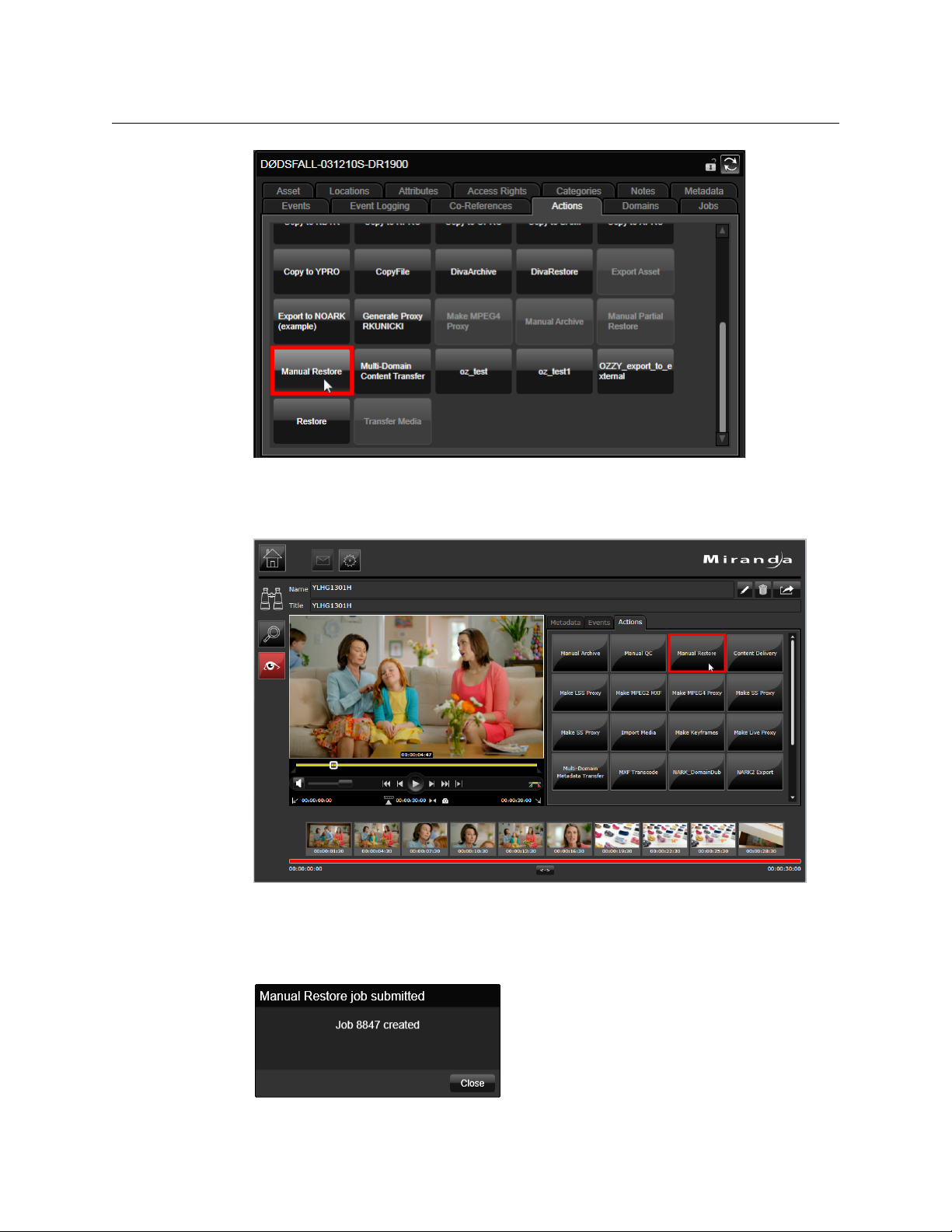
User Operations
Manually Archiving and Restoring Jobs
Fig. 10-4: Actions tab of the Asset layout, showing the Manual Restore button.
The same operations can be carried out with the iTX Smart Client, provided the
relevant Action Button has been configured beforehand:
74
Fig. 10-5: Manual Restore in Smart Client
4 Jobs are sent to the Opus Service and given a unique Job ID in order to enable the
operator to track its progress. Opus then forwards the job onto Delivery Manager,
which in turn passes it to the appropriate endpoint.
Page 81

Partial Restore jobs (DIVA only)
A partial restore is performed when only a marked segment of an archived clip is required
for playout. A user can mark up a section of media via the iTX Desktop or SmartClient and
the DIVArchive management software will create and export a copy clip that just contains
the media required for playout.
Delivery Manager
Configuration and Setup Guide
Instead of the whole media clip being transferred t
with an in-point and an out-point points is generated as a new physical file by the
DIVArchive.
o an iTX location, the section marked up
Note: Currently, manual Partial Restores only work with DIVArchive systems
with self-contained Quicktime MOVs.
To ensure all frames of marked clip are available in a long GOP file structure, the file may
contain a small additional number of frames to the amount as specified by the newly
created Asset. These are not shown when previewing or playing out between the marked
points.
Partial restores can be perform from both the iTX Desktop's Asset la
Asset workspace.
To mark up a clip and perform a partial restore:
1 Open either the Asset
Client.
2 Search for an asset known to exist on the DIVArchive.
3Click the Ac
4 Mark the required in-point and out-point by dragging the green and red markers to the
ap
propriate timecodes, as pictured below:
tions tab.
layout on the iTX Desktop or the Asset workspace in Smart
yout or SmartClient
5Click Manual Partial Restore. The Submit Manual Partial Restore job dialog appears.
6 Click on a priority button (L
created.
7Click OK.
The name of the new media file is based on that of the par
Created date and time stamp.
Alternatively, if a ShotList contains a reference to a segment of a clip that is stored on a
Archive, when it is loaded as an asset for playout, the DIVA based media will be partially
DIV
restored as part of the media required.
ow, Medium or High) and click Submit. A new job will be
Viewing a partially restored media file
Partially restored video clips can be viewed in the asset media viewer in iTX Desktop's Asset
layout or the SmartClient Asset workspace.
To view a partially restored media file:
1 Open either the Asset
Client.
layout on the iTX Desktop or the Asset workspace in Smart
ent co-reference but with a
75
Page 82

User Operations
Viewing a partially restored media file
2 Search for an asset that has been partially stored and select it.
When the media viewer in the iTX Desktop is set to Auto Load it will, by default, load
the largest file available for the clip. However, if set to
available media files that contain the complete media for that particular asset.
For each asset the following information is shown:
• The location type (e.g. proxy or iTX)
• The storage format or media container (e.g. MPEG-4)
• The location (e.g. SVR2561)
• A time line graphic that represents the length and position of the clip in relation to
the par
The gray section of the time line represents the length of the media containing that
p. The yellow section represents the length of media in the specific location. The
cli
triangular markers show the in and out points of the clip.
3 Hover the mouse pointer over an entry to view more details, as pictured below:
Manual, it will list the locations of
ent media.
4 Click on an entry in the list. The corresponding clip loads in the viewer.
Note: Timelines only show for clips that have locations for partially restored
media.
5Click the All Media tab to view full details of all media files that co-reference the same
parent media:
76
Page 83

Delivery Manager
Configuration and Setup Guide
6Click Show Clip Extents to toggle the guide lines that show the in and out points for
the clip.
7 Select a type from the Show T
ypes drop down list to filter the types of media show (e.g.
proxy files).
The color coding identifies the locations of the associat
ed media including partially
restored files:
Color Description
Green The file contains all the media for the current video clip.
Orange The file contains a portion of the media for the current video clip.
Red The file contains no media for the current video clip.
77
Page 84

User Operations
Exporting ShotLists from the iTX Desktop and SmartClient
Exporting ShotLists from the iTX Desktop and SmartClient
Another manual operation that can be carried out from the iTX Desktop and the
SmartClient is the ability to export shot lists to a remote network share.
A ShotList is a simple sequence of sections fr
exported manually, all the media assets required for the sequence are transferred from the
DIVArchive to a specified network shared directory. An operator might want to export the
media required to a craft editing system in order for the sequence to be edited and
compiled into a single clip.
om a number of clips. When a ShotList is
Note: To perform ShotList exports there are two workflows that must be
installed. See C
To export shot lists to a remote network share:
1 In the SmartClient, produce a ShotList or load one into the Asset Layout of the iTX
Desktop.
2 Select the T
3In the Actions tab, then click the Cache ShotList button.
The export is a two stage process:
• All the required media is checked and if any does not have a current iTX location,
Delivery Manager creates jobs to import it into iTX.
If any segments of the ShotList project are from clips that have a DIVArchive location,
an aut
• When all the media has been verified to have an iTX Location, all the parts of the
ShotList ar
folder with the ShotList project's name.
arget Project tab.
omatic partial restore is issued for the required media.
e then copied to the remote network share into an automatically created
onfiguring the ShotList Export workflow on page 65.
78
Page 85

Exporting ShotList XML
If the ShotList is being exported for craft editing, in an application such as Final Cut Pro,
then an XML file containing the in and out points for each shot in the list can also be
exported from the SmartClient.
To exp o rt a Sho t Lis t XML :
1 In the SmartClient, produce a ShotList or load one into the Asset Layout of the iTX
Deskt
op.
2 Select the T
3In the Ac
arget Project tab.
tions tab, click FCP Export.
Delivery Manager
Configuration and Setup Guide
SmartClient opens the FCP Export dialog.
4 Select the machine that you want SmartClient to copy the required media files to. Click
Ne
xt.
SmartClient opens the S
5 Enter a name for the FCP project file and select the folder where you want SmartClient
to plac
e this file. Click Save to close the dialog.
SmartClient creates an FCP project file from the project clip and copies the required
media
files to the specified machine.
ave As dialog.
79
Page 86

User Operations
Exporting ShotList XML
80
Page 87

Delivery Manager Feature Set
This chapter details Delivery Manager’s feature set and which of those features each
endpoint supports.
Summary
Delivery Manager Feature Set . . . . . . . . . . . . . . . . . . . . . . . . . . . . . . . . . . . . . . . . . . . . . . . . . . . . . . . . 81
Supported Features by Endpoint . . . . . . . . . . . . . . . . . . . . . . . . . . . . . . . . . . . . . . . . . . . . . . . . . . . . . . 82
Delivery Manager Feature Set
The table below describes each of these features, followed by another table that identifies
the features supported by each of the endpoint drivers:
Feature Description
Content changes If content is added, deleted or modified on the store or location the end-
point is configured to monitor, it reacts by updating the asset's record
within the iTX database and then re-import or delete the appropriate file
as required.
Monitor folder
(“drop box”)
Process XML files The endpoint can update Asset Records within the iTX database by pro-
Check for “place
holder” assets
Processes creates The endpoint creates, or in some cases updates, an asset record when
The endpoint specifically monitors a folder on a remote content store.
When new assets arrive in that location, they are processed. Likewise, if
any assets are deleted or modified in that location, the asset and its
record are updated, depending on the specific configuration of the end
point type.
cessing XML based metadata files that are deposited at the location it is
configured to monitor.
The endpoint can process new asset records that as of yet do not have an
actual associated media file. In production terms, a Place Holder Clip.
importing new media.
-
Processes deletes The endpoint deletes an asset and its associated record if requested to do
so.
Processes renames If an asset is renamed in Opus, via the SmartClient or iTX Desktop then
the endpoint can process the action.
Find Colossus/iTX
1.4 system content
The endpoint can actively query a store, archive or external content management system to locate a file requested via Missing Materials Manager.
81
Page 88

Delivery Manager Feature Set
Supported Features by Endpoint
Feature Description
Import The endpoint either copies a file to an iTX location and updates the asset
ecord to state the media now exists in iTX exclusively; or it physically
r
'moves' the file by copying it to iTX then deleting the original and updating the asset record accordingly.
Archive The endpoint copies or moves an asset to an external archive (depending
configuration) and updates the asset record with the media's new
on
External location.
Delete The endpoint processes delete requests for their store or archive and
passes these r
Reference media The endpoint performs the ingest of referenced based media, automati-
cally handling all associated essence files, including audio, video and xml
containing asset data.
equests to the store or archive management software.
Supported Features by Endpoint
The feature set available for each endpoint is shown in this table:
Feature FTP
Content changes
Monitor folder
(“drop box”)
Process XML files
Check for “place holder”
assets
Processes creates
Processes deletes
Processes renames
Find content
Import/restore
Archive
Delete
Reference media (MOV,
MXF)
Pitch
Blue
CIFS/
SMB DIVA
Mass
Tech
Path
Fire
Ardome SGL Core
82
Note: The Pitch Blue Archive endpoint uses FTP for the transfer of files to
and from the archive, so Pitch Blue and FTP share the same functionality
options.
Page 89

Delivery Manager
Configuration and Setup Guide
83
Page 90

Delivery Manager Feature Set
Supported Features by Endpoint
84
Page 91

Troubleshooting
Delivery Manager can provide diagnostic information that can be used to identify and
resolve problems.
• A Delivery Manager endpoint cannot access the store or connect to the archive
management software it is configured to use.
• Delivery Manager cannot connect to the Locator Service and the iTX database.
• A media transfer has failed.
The following diagnostic areas can help you solve these problems.
Summary
Basic System Checks . . . . . . . . . . . . . . . . . . . . . . . . . . . . . . . . . . . . . . . . . . . . . . . . . . . . . . . . . . . . . . . . . . 85
Monitoring Status and Health . . . . . . . . . . . . . . . . . . . . . . . . . . . . . . . . . . . . . . . . . . . . . . . . . . . . . . . . 86
Running Diagnostics on the Delivery Manager Service . . . . . . . . . . . . . . . . . . . . . . . . . . . . . . . . 86
Generating Trace Logs in Delivery Manager . . . . . . . . . . . . . . . . . . . . . . . . . . . . . . . . . . . . . . . . . . . 87
Monitoring Active Jobs in Delivery Manager . . . . . . . . . . . . . . . . . . . . . . . . . . . . . . . . . . . . . . . . . . 89
Verifying the Database Update . . . . . . . . . . . . . . . . . . . . . . . . . . . . . . . . . . . . . . . . . . . . . . . . . . . . . . . 89
The most common problems are:
Basic System Checks
Before attempting to diagnose any Delivery Manager faults there are a few basic system
checks you can carry out that may save you a lot of time.
• If you had to stop the service while making changes to configurations, check that
Delivery Manager is running.
• In the configuration profile, make sure the Enabled checkbox is checked for each
endpoint.
• Check that other framework services essential for Delivery Manager's operation are also
up and running, for example:
• Locator Service
•Opus service
85
Page 92

Troubleshooting
Monitoring Status and Health
Monitoring Status and Health
Each endpoint running from a single instance of Delivery Manager has its own control
panel tab. A health light indicates the state of the endpoint.
A green light indicates the endpoint can access the store or is communicating
with the ar
A red light indicates that Delivery Manager has a connection or access problem,
either with the iT
The Service Details tab shows a brief summary of the errors logged in the Health Test
windo
w to the right of the Service Info details.
If errors are listed here, then click the diagnostics tab to run a diagnostic test that will
supply
more detailed information on the errors.
Core Endpoint Connection Failure
If Delivery Manager cannot connect to the specified Colossus/iTX 1.4 database, an error will
show in the Delivery Manager logging window. The connection status indicator for the
Core endpoint will also be red.
chive system it is configured for.
X system, the store or archive management software.
On connection to the Colossus/iTX 1.4 database,
functions or procedures have been installed on the Colossus/iTX 1.4 database. Delivery
Manager will show a warning state if any of the required database objects (functions and
procedures) are missing and an error will be displayed in the logging window. For details on
how to run these stored procedures against the Colossus/iTX 1.4 database, see Preparing
the Database for Core Endpoints, o
n page 40.
Delivery Manager checks to see if any new
Running Diagnostics on the Delivery Manager Service
You can run a full Delivery Manager Diagnostic Report from the Diagnostics tab by clicking
the bar button labeled Generate Diagnostic Report at the top. This will test all connections
required by Delivery Manager including Locator Service and iTX database. It will also report
on the ability to connect to the configured stores and archives.
If the problem is connecting with the iTX system itself see the iT
Guide for troubleshooting database or Locator Service connection issues.
If the problem lies with accessing the store
software, we recommend checking the network connection.
To check network connectivity:
1 On the Delivery Manager server, open an MS-DOS Command Prompt. In Windows, it
n usually be found on the Start menu under Accessories > Command Prompt.
ca
2 From the Command Prompt window, type
network store, for example
3 Type ping again, followed by the address of the network store, for example
dev_qa_2.3.
Wait for a response.
ping 192.168.170.82:9002. Wait for a response.
or connecting to the archive management
ping followed by the IP address of the
X System Administration
ping
86
Page 93

Delivery Manager
Configuration and Setup Guide
4 If you can ping the store's IP address and resolve its domain name, then re-run the
Delivery Manager configuration tool and check your settings for this particular
endpoint.
Depending on the endpoint type, you may be able to test the connection to the
net
work share from the configuration tool, via the Test Connection button, as pictured
below:
Generating Trace Logs in Delivery Manager
If you are still experiencing problems, Trace Logs can be used to gather detailed
information about the errors. This can be managed either in Delivery Manager Service or
via the iTX Desktop.
Viewing trace logs from the Delivery Manager Service
If any transfers are failing or you have connection issues, these will be reported in the trace
logs. Reconciling the information in these logs require expert knowledge and therefore
should be sent to Grass Valley.
To view trace logs:
1 From the Delivery Manager Service user interface, select the Tr
2In the Catego
3 To enable the highest level of detail possible f
bottom of the List tab.
ries window, check the Delivery Manager checkbox.
or logging, check the Verbose box at the
ace Logs tab.
87
Page 94

Troubleshooting
Viewing trace logs from the iTX Desktop
Note: In this mode, the amount of logging carried out will generate very
large log files very quickly. It is therefore not advised to run in this mode any
longer than necessary.
Creating a log file from Delivery Manager
The logging is not automatically written to a log file. The information is retained by the
Opus service. In order to write the logs to a log file, a Logging Profile must be loaded. This is
a special XML configuration file that tells Delivery Manager the categories of information,
the level of detail and where you wish the file to be created and what you want it to be
called.
To loa d a prof ile:
1 On the Trace Logs tab, click the Lo
2 Delivery Manager logs are written as simple text files with a
3 Log files can then be zipped up and sent to Grass Valley.
You may also want to highlight any errors logged in List window, using the right mouse
butt
on, then copy and paste the log entries into a text file to send to Grass Valley
Support.
ad Profile button.
.log file extension.
Note: Remember to turn off logging after you have acquired the informa-
tion you need, as log files can become very large and fill hard disk space if
ing is left switched on.
logg
To acquire a logging profile configuration file, contact Grass Valley support or your Grass
Valley sales representative.
Viewing trace logs from the iTX Desktop
Within the iTX Desktop, the Logging layout allows you to view any logs being generated by
any service in your iTX system. It allows you to connect to each endpoint and select the
logging categories you wish to see.
To view any endpoint's logging from the Logging Layout:
1 In the top right of the layout, click Remot
ONLY).
2Click Ca
3Click Ser
labeled
4In the L
5 In order to stop the logging momentarily while y
Pause. You can also configure the level of logging you wish to see (Information,
Verbose, Warning or Errors) via the checkboxes at the bottom of the logging window.
tegory, then select Opus.
vice Provider, then select any one of the listed named endpoints (they will be
endpoint: followed by the name you gave it on initial configuration).
og Categories column check the Delivery Manager checkbox.
e Service Trace Logging (FOR DEBUG USE
ou read any on screen messages, click
88
Page 95

Monitoring Active Jobs in Delivery Manager
The Active Jobs tab lists all the jobs currently being progressed by this instance of Delivery
Manager.
The table below describes the columns in this dialog:
Column Description
Delivery Manager
Configuration and Setup Guide
Job Name
Job ID
Filename
Status DisplaysDelivery Manager the current status of any job in the queue. It has
Lists the type of job in progress.
Indicates the order that the jobs are being progressed in and can be used to
track the progress of any particular job in the trace logs.
Displays the original name of the file on the remote store and the network path
from where it is being copied
four states that are important to the user:
Idle• - this means the job is either waiting to start or is waiting for a user
response before moving to the next stage (Media QC for instance).
Active• - The job is currently in progress (a file is in mid transfer for exam-
ple)
Aborted• - The Job has either failed or has been cancelled by a user
action. In the case of a failure, use the Job ID to track the job's progress
through the trace logs.
Completed• - The job has now finished completely (the file has trans-
ferred and the database has been updat
In diagnostic terms, this is the most important column.
Verifying the Database Update
Once the batch files have been executed, you can verify the Core or iTX 1.4 database has
been updated successfully by checking for the following:
• ‘Trigger On’ table
• Store procedures
•Required functions
• The Service Broker is present
ed with new metadata etc.).
Verifying the 'Trigger On' table is present
To verify the ‘Trigger On’ table is present:
1 Using your SQL Server Manager application,
2 Locate the table
3 Check there is a table named otg_OPUS_DM_Core_PushClipChanges.
dbo.Omnibus_CLD_ClipDetails and expand Triggers.
access the Core/iTX1.4 database.
89
Page 96

Troubleshooting
Verifying the Stored Procedures are present
Verifying the Stored Procedures are present
To verify the stored procedures are present:
1 Using your SQL Server Manager application expand Da
Stored procedures.
2 Check the following stored procedures have been added:
dbo.osp_OPUS_DM_Core_GetAssetXMLFromAssetName
dbo.osp_OPUS_DM_Core_GetAssetXMLFromAssetNameWithMetadata
Verifying the required functions are present
To verify the required functions are present:
1 Using your SQL Server Manager application expand Da
Functions > Scalar-valued Functions.
2 The following functions should have been added:
ofn_g3Media_ContnetSegmentType_GetPathFromID
ofn_OPUS_XML_GetContentEventsAsXML
ofn_OPUS_XML_MetadataEventsAsXML
tabase > Programmability >
tabase > Programmability >
Verifying the Service Broker is present
Note: This step is not required for SQL 2005.
To verify the service broker is present:
1 Using your SQL Server Manager application, select Properties > Options (Service
Broker)
2Check that
3Expand Database > Service Broker > Message Types
4Check for
5Expand Database->Service Broker->Contracts
6Check for
7Expand Database->Service Broker->Queues
8Check for
9Expand Database->Service Broker->Service
10 Check for
Broker Enabled = True.
MessageContractType
DMCoreContract
dbo.DMCoreQueue
DMCoreService
90
Page 97

Grass Valley Technical Support
For technical assistance, contact our international support center, at
1-800-547-8949 (US and Canada) or +1 514 333 1772.
To obtain a local phone number for the support center nearest you, please consult the
Contact Us section of Grass Valley’s Web site (
An online form for e-mail contact is also available from the Web site.
Corporate Head Office
Grass Valley
3499 Douglas-B.-Floreani
St-Laurent, Quebec H4S 2C6
Canada
Telephone: +1 514 333 1772
Fax: +1 514 333 9828
www.grassvalley.com
Contact Us
www.grassvalley.com).
 Loading...