

Page 1
User Guide
Version 6.01
M407-9900-222
2 May 2014
Page 2

i
Copyright and Trademark Notice
Copyright © 2001-2014, Miranda Technologies Partnership.
Belden, Belden Sending All The Right Signals, and the Belden logo are trademarks or registered trademarks of Belden Inc. or its affiliated companies in the United States and other jurisdictions. Miranda, iControl, Kaleido-X, Kaleido-K2, Kaleido-Alto, NVision, and Densité are
trademarks or registered trademarks of Miranda Technologies Partnership. All rights reserved.
Belden Inc., Miranda Technologies Partnership and other parties may also have trademark
rights in other terms used herein.
ATTENTION: Please read the following terms and conditions carefully. By using iRouter documentation, you agree to the following terms and conditions:
Miranda Technologies Partnership hereby grants permission and license to owners of iRouter
to use their product manuals for their own internal business use. Manuals for Miranda products may not be reproduced or transmitted in any form or by any means, electronic or
mechanical, including photocopying and recording, for any purpose unless specifically authorized in writing by Miranda.
A Miranda manual may have been revised to reflect changes made to the product during its
manufacturing life. Thus, different versions of a manual may exist for any given product. Care
should be taken to ensure that one obtains the proper manual version for a specific product
serial number.
Information in this document is subject to change without notice and does not represent a
commitment on the part of Miranda.
Warranty Policies
Warranty information is available in the Support section of the Miranda Web site
(www.miranda.com).
Title iC Router Version 6.01 User Guide
Part Number M407-9900-222
Revision Date 2 May 2014 1:08 pm
ii
Page 3

Table of Contents
1 Introduction . . . . . . . . . . . . . . . . . . . . . . . . . . . . . . . . . . . . . . . . . . . . 1
Overview . . . . . . . . . . . . . . . . . . . . . . . . . . . . . . . . . . . . . . . . . . . . . . . . . . . . . . . . . . . . . . . . . . . . . . . . . . 1
Communications with Routers . . . . . . . . . . . . . . . . . . . . . . . . . . . . . . . . . . . . . . . . . . . . . . . . . . . . . 1
User Interfaces Available with iControl Router Software . . . . . . . . . . . . . . . . . . . . . . . . . . . . .2
Configuration Interface . . . . . . . . . . . . . . . . . . . . . . . . . . . . . . . . . . . . . . . . . . . . . . . . . . . . . . . . 2
Operating Interface . . . . . . . . . . . . . . . . . . . . . . . . . . . . . . . . . . . . . . . . . . . . . . . . . . . . . . . . . . . 2
2 Operating Interface . . . . . . . . . . . . . . . . . . . . . . . . . . . . . . . . . . . . . 3
Key Concepts . . . . . . . . . . . . . . . . . . . . . . . . . . . . . . . . . . . . . . . . . . . . . . . . . . . . . . . . . . . . . . . . . . . . . .3
Matrix View . . . . . . . . . . . . . . . . . . . . . . . . . . . . . . . . . . . . . . . . . . . . . . . . . . . . . . . . . . . . . . . . . . . 3
Single Bus Window . . . . . . . . . . . . . . . . . . . . . . . . . . . . . . . . . . . . . . . . . . . . . . . . . . . . . . . . . . . . 6
Router Status Window . . . . . . . . . . . . . . . . . . . . . . . . . . . . . . . . . . . . . . . . . . . . . . . . . . . . . . . . 11
Exclusion Editor . . . . . . . . . . . . . . . . . . . . . . . . . . . . . . . . . . . . . . . . . . . . . . . . . . . . . . . . . . . . . . 13
Salvo Editor . . . . . . . . . . . . . . . . . . . . . . . . . . . . . . . . . . . . . . . . . . . . . . . . . . . . . . . . . . . . . . . . . . 17
Groups Editor . . . . . . . . . . . . . . . . . . . . . . . . . . . . . . . . . . . . . . . . . . . . . . . . . . . . . . . . . . . . . . . . 20
Destination locks . . . . . . . . . . . . . . . . . . . . . . . . . . . . . . . . . . . . . . . . . . . . . . . . . . . . . . . . . . . . . 23
Detailed Directions . . . . . . . . . . . . . . . . . . . . . . . . . . . . . . . . . . . . . . . . . . . . . . . . . . . . . . . . . . . . . . 24
Opening the Matrix View . . . . . . . . . . . . . . . . . . . . . . . . . . . . . . . . . . . . . . . . . . . . . . . . . . . . . 24
Opening the Single Bus Window . . . . . . . . . . . . . . . . . . . . . . . . . . . . . . . . . . . . . . . . . . . . . . 27
Opening the Router Status Window . . . . . . . . . . . . . . . . . . . . . . . . . . . . . . . . . . . . . . . . . . . 29
Opening Salvo Editor . . . . . . . . . . . . . . . . . . . . . . . . . . . . . . . . . . . . . . . . . . . . . . . . . . . . . . . . . 30
Opening Exclusion Editor . . . . . . . . . . . . . . . . . . . . . . . . . . . . . . . . . . . . . . . . . . . . . . . . . . . . . 30
Opening Groups Editor . . . . . . . . . . . . . . . . . . . . . . . . . . . . . . . . . . . . . . . . . . . . . . . . . . . . . . . 31
3 Routing Switchers Tips and Tricks . . . . . . . . . . . . . . . . . . . . . . 33
General . . . . . . . . . . . . . . . . . . . . . . . . . . . . . . . . . . . . . . . . . . . . . . . . . . . . . . . . . . . . . . . . . . . . . . . . . . 33
Nevion . . . . . . . . . . . . . . . . . . . . . . . . . . . . . . . . . . . . . . . . . . . . . . . . . . . . . . . . . . . . . . . . . . . . . . . . . . 33
Network Compact Protocol (Default Driver for VikinX Compact Routers) . . . . . . . 33
Network Modular Protocol (Control Protocol for VikinX Modular Routers) . . . . . . 34
Leitch . . . . . . . . . . . . . . . . . . . . . . . . . . . . . . . . . . . . . . . . . . . . . . . . . . . . . . . . . . . . . . . . . . . . . . . . . . . 35
Troubleshooting . . . . . . . . . . . . . . . . . . . . . . . . . . . . . . . . . . . . . . . . . . . . . . . . . . . . . . . . . . . . . 36
How to get Firmware Version Number? . . . . . . . . . . . . . . . . . . . . . . . . . . . . . . . . . . . . . . . 36
Utah Scientific RCP-3 (SC-4 Controller Ethernet Only) . . . . . . . . . . . . . . . . . . . . . . . . . . . . . . 36
Utah Scientific RCP-1 (SC-3 Controller) . . . . . . . . . . . . . . . . . . . . . . . . . . . . . . . . . . . . . . . . . . . . 37
Troubleshooting . . . . . . . . . . . . . . . . . . . . . . . . . . . . . . . . . . . . . . . . . . . . . . . . . . . . . . . . . . . . . 38
Utah Scientific AVS . . . . . . . . . . . . . . . . . . . . . . . . . . . . . . . . . . . . . . . . . . . . . . . . . . . . . . . . . . . . . . . 38
Troubleshooting . . . . . . . . . . . . . . . . . . . . . . . . . . . . . . . . . . . . . . . . . . . . . . . . . . . . . . . . . . . . . 39
1
Page 4

toc
Philips . . . . . . . . . . . . . . . . . . . . . . . . . . . . . . . . . . . . . . . . . . . . . . . . . . . . . . . . . . . . . . . . . . . . . . . . . . . 39
Troubleshooting . . . . . . . . . . . . . . . . . . . . . . . . . . . . . . . . . . . . . . . . . . . . . . . . . . . . . . . . . . . . . 40
Digipath . . . . . . . . . . . . . . . . . . . . . . . . . . . . . . . . . . . . . . . . . . . . . . . . . . . . . . . . . . . . . . . . . . . . . . . . . 40
Troubleshooting . . . . . . . . . . . . . . . . . . . . . . . . . . . . . . . . . . . . . . . . . . . . . . . . . . . . . . . . . . . . . 40
Thomson / Grass Valley GVG Series 7000 Native Protocol . . . . . . . . . . . . . . . . . . . . . . . . . . 40
Troubleshooting . . . . . . . . . . . . . . . . . . . . . . . . . . . . . . . . . . . . . . . . . . . . . . . . . . . . . . . . . . . . . 43
Lightwave Matrix-Hub 1000 . . . . . . . . . . . . . . . . . . . . . . . . . . . . . . . . . . . . . . . . . . . . . . . . . . . . . . 43
Troubleshooting . . . . . . . . . . . . . . . . . . . . . . . . . . . . . . . . . . . . . . . . . . . . . . . . . . . . . . . . . . . . . 44
Snell (Pro-Bel) . . . . . . . . . . . . . . . . . . . . . . . . . . . . . . . . . . . . . . . . . . . . . . . . . . . . . . . . . . . . . . . . . . . . 44
SW-P-08 (General Remote Control Protocol) . . . . . . . . . . . . . . . . . . . . . . . . . . . . . . . . . . . 44
SW-P-02 (General Switcher Communication Protocol) . . . . . . . . . . . . . . . . . . . . . . . . . 44
NVISION . . . . . . . . . . . . . . . . . . . . . . . . . . . . . . . . . . . . . . . . . . . . . . . . . . . . . . . . . . . . . . . . . . . . . . . . . 45
NVISION Ethernet Protocol - Enterprise Router . . . . . . . . . . . . . . . . . . . . . . . . . . . . . . . . 45
NVISION Ethernet Protocol - Enterprise Router (Logical) . . . . . . . . . . . . . . . . . . . . . . . 50
NVISION Ethernet Protocol - Compact Router . . . . . . . . . . . . . . . . . . . . . . . . . . . . . . . . . 52
Pesa . . . . . . . . . . . . . . . . . . . . . . . . . . . . . . . . . . . . . . . . . . . . . . . . . . . . . . . . . . . . . . . . . . . . . . . . . . . . . 52
CPU Link Protocol No.1 or P1 (Pesa) . . . . . . . . . . . . . . . . . . . . . . . . . . . . . . . . . . . . . . . . . . . 52
Unsolicited Status Protocol (Pesa USP) . . . . . . . . . . . . . . . . . . . . . . . . . . . . . . . . . . . . . . . . 53
Sony . . . . . . . . . . . . . . . . . . . . . . . . . . . . . . . . . . . . . . . . . . . . . . . . . . . . . . . . . . . . . . . . . . . . . . . . . . . . . 55
Quintech . . . . . . . . . . . . . . . . . . . . . . . . . . . . . . . . . . . . . . . . . . . . . . . . . . . . . . . . . . . . . . . . . . . . . . . . 55
Quick Info . . . . . . . . . . . . . . . . . . . . . . . . . . . . . . . . . . . . . . . . . . . . . . . . . . . . . . . . . . . . . . . . . . . . 55
Detailed Info . . . . . . . . . . . . . . . . . . . . . . . . . . . . . . . . . . . . . . . . . . . . . . . . . . . . . . . . . . . . . . . . . 56
4 Configuration Interface . . . . . . . . . . . . . . . . . . . . . . . . . . . . . . . . 59
Overview . . . . . . . . . . . . . . . . . . . . . . . . . . . . . . . . . . . . . . . . . . . . . . . . . . . . . . . . . . . . . . . . . . . . . . . . 59
System Recommendations . . . . . . . . . . . . . . . . . . . . . . . . . . . . . . . . . . . . . . . . . . . . . . . . . . . . . . . 59
Detailed Directions . . . . . . . . . . . . . . . . . . . . . . . . . . . . . . . . . . . . . . . . . . . . . . . . . . . . . . . . . . . . . . 60
Configuring Routers . . . . . . . . . . . . . . . . . . . . . . . . . . . . . . . . . . . . . . . . . . . . . . . . . . . . . . . . . . 60
Configuring Routers Dynamically . . . . . . . . . . . . . . . . . . . . . . . . . . . . . . . . . . . . . . . . . . . . . 85
Contact Us. . . . . . . . . . . . . . . . . . . . . . . . . . . . . . . . . . . . . . . . . . . . . . . . 95
2
Page 5

Overview
The Miranda iControl Router Software allows you to create a virtual routing environment
where actual physical router resources are deployed and controlled by software into a
customized configuration optimized for your operational needs. Large routers can be
operated as if they were multiple smaller routers. For example, a 64 × 64 router can be
operated as if it were three separate smaller routers: for instance, a 64 × 15 router, a 12 × 5
router and a 32 × 44 router. Control and monitoring are handled by software, and are readily
changed. Each operator benefits by seeing only the resources actually being used. This
software can also be used as a bridge interface between a Kaleido or iControl Web system and
a routing device. In this configuration, it will be used to update UMD text, and for router
control functions initiated from the Kaleido or iControl Web user interface. The software
includes the following features:
Introduction
• bridge interface via TCP-IP for Kaleido and iControl Web software
• distributed architecture
• highly configurable
• unlimited router size
1
• unlimited number of levels
• support for logical routers
• support for a mix of different frame types from different manufacturers
Communications with Routers
The host computer and the routing devices you wish to control must be interconnected by a
serial or Ethernet cable. Most of the supported routers are serial (RS-422 or RS-232) devices.
Some newer devices may support TCP\IP connection.
Install the appropriate connection, either by using dedicated cabling or through an existing
network.
See also
For more information, see "Routing Switchers Tips and Tricks" on page 33.
1. Exceptionally, the iControl Router driver for the Snell SW-P-08 protocol does not support, by default, a matrix larger
than 1024 × 1024. If your router matrix requirements exceed this upper limit using this protocol, contact Miranda
technical support.
Page 6

Introduction
User Interfaces Available with iControl Router Software
User Interfaces Available with iControl Router Software
Configuration Interface
The configuration interface, called iControl Router Configurator, is used for router setup and
configuration. Use this application to define physical and logical routers.
Ter m Description
Physical Router A physical router represents the connection to your existing router (RS-232/422 or TCP). Configure one
physical router for each device you wish to control from the iControl Router software.
Logical Router A logical router represents an entire physical router, or a subset of a physical router. The operating
interfaces handle logical routers.
For instance, if you configured one 16 × 16 physical router, you can create two 8 × 8 logical routers with
levels 0 and 1.
See also
For more information, see "Configuration Interface" on page 59.
Operating Interface
The operating interfaces called Matrix View and Single Bus are client applications used to
monitor and control the logical routers that you defined in iControl Router. They are available
from the iControl Router Control Web page.
See also
For more information, see "Operating Interface" on page 3.
2
Page 7
Key Concepts
The operating interface consists of several components:
• Matrix view is designed to provide extended functionality and be a visual representation
of the status for the whole logical router (see page 3).
• Single Bus window is an interface designed to control one router destination (or group of
destinations) at a time (see page 6).
• Router Status window displays router status and labels of all destinations or groups of
destinations (see page 11).
• Exclusion Editor allows you to exclude specified router inputs from appearing on
specified outputs. For example, you may wish to inhibit a VTR’s output from being fed back
to its input (see page 13).
• Salvo Editor allows you to create and edit a configuration of crosspoint closures
(see page 17).
• Groups Editor allows you to create and edit groupings of destinations (see page 20).
Operating Interface
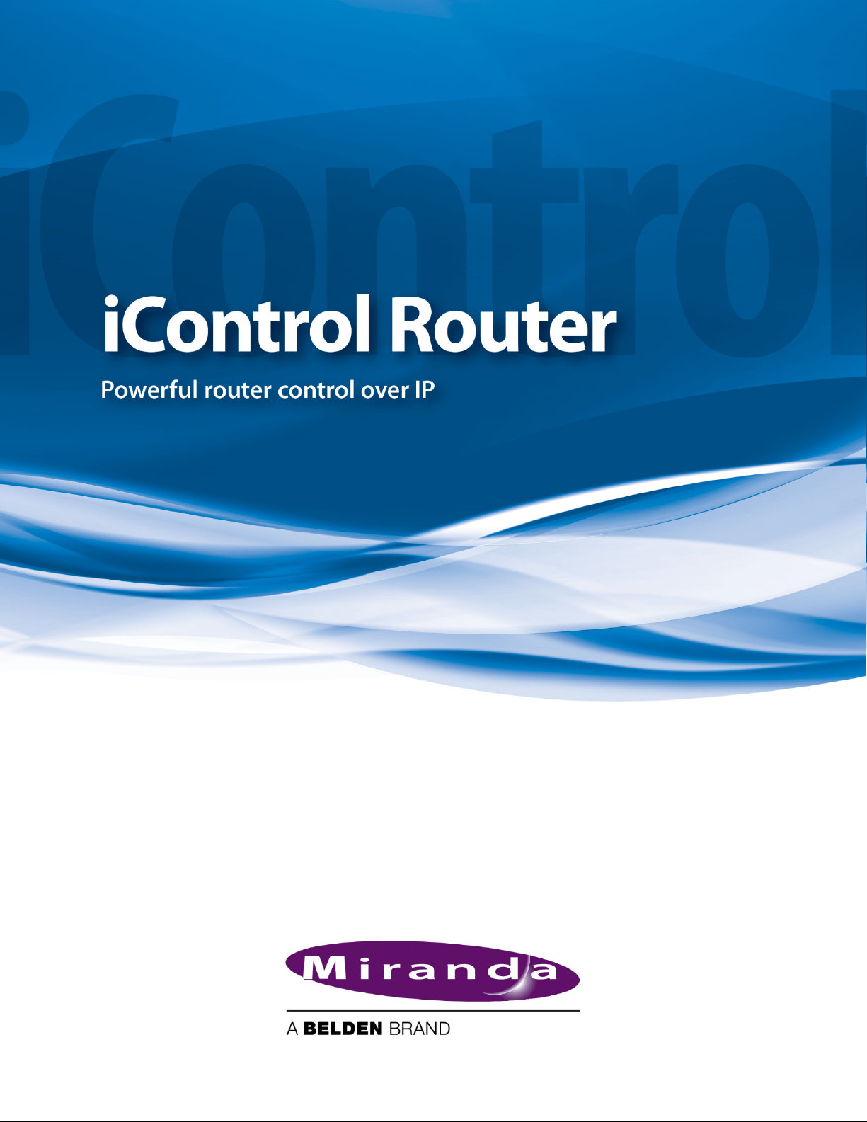
Matrix View
The Matrix View interface allows you to switch crosspoints during operation. Three areas at
the bottom of the window enable crosspoint operation in different modes.
Page 8
Operating Interface
Matrix View Common Tasks
See also
For more information, see:
• "Matrix View Common Tasks" on page 4
• "Matrix Menus" on page 5
• "Destination locks" on page 23
• "Opening the Matrix View" on page 24
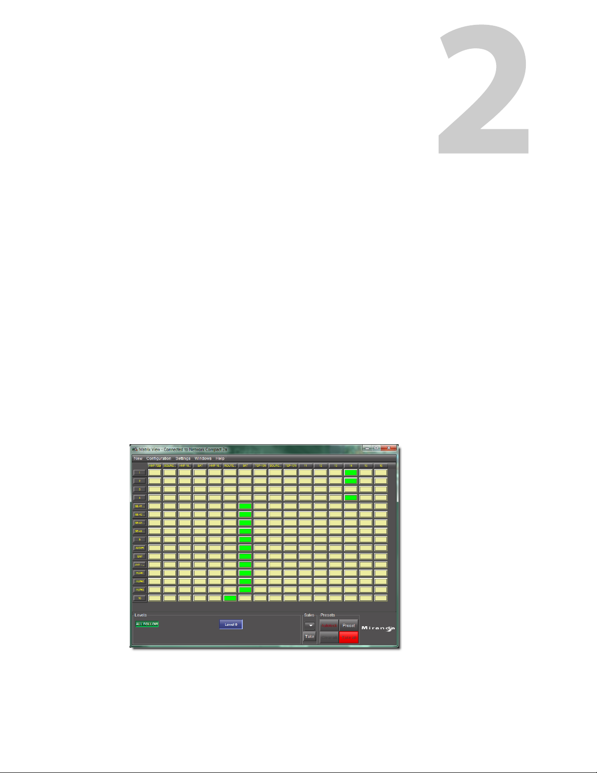
Matrix View Common Tasks
To do this... ...do this...
Set the system to store all changes made in Matrix view, but
NOT implement those changes until Take a ll is clicked.
In the Presets area, select Preset.
Set the system to implement all changes made in the Matrix
view as soon as they are entered.
Select one or more levels to be switched In the Levels area, enable the button(s) corresponding to
Set the system to switch all levels In the Levels area, enable ALL FOLLOW.
Set the system to automatically lock changes once they are
taken
In the Presets area, clear Preset.
one or more levels, as required.
In the Presets area, enable Autolock.
4
Page 9
iControl Router
User Guide
(
Continued
)
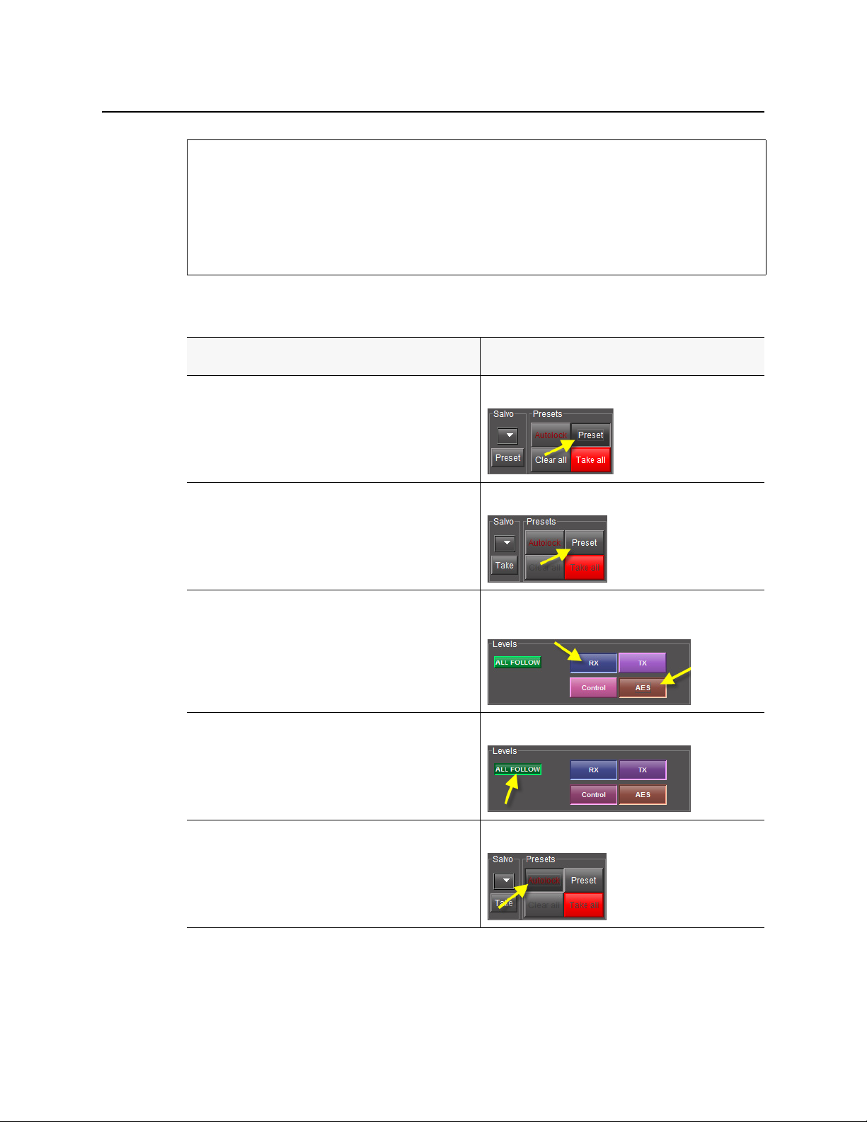
To do this... ...do this...
Apply a salvo In the Salvo area, select a salvo from the list, and then click
Tak e.
Choose a destination group
1. In the Matrix area, click on the column header box
designating the source.
2. Select a group.
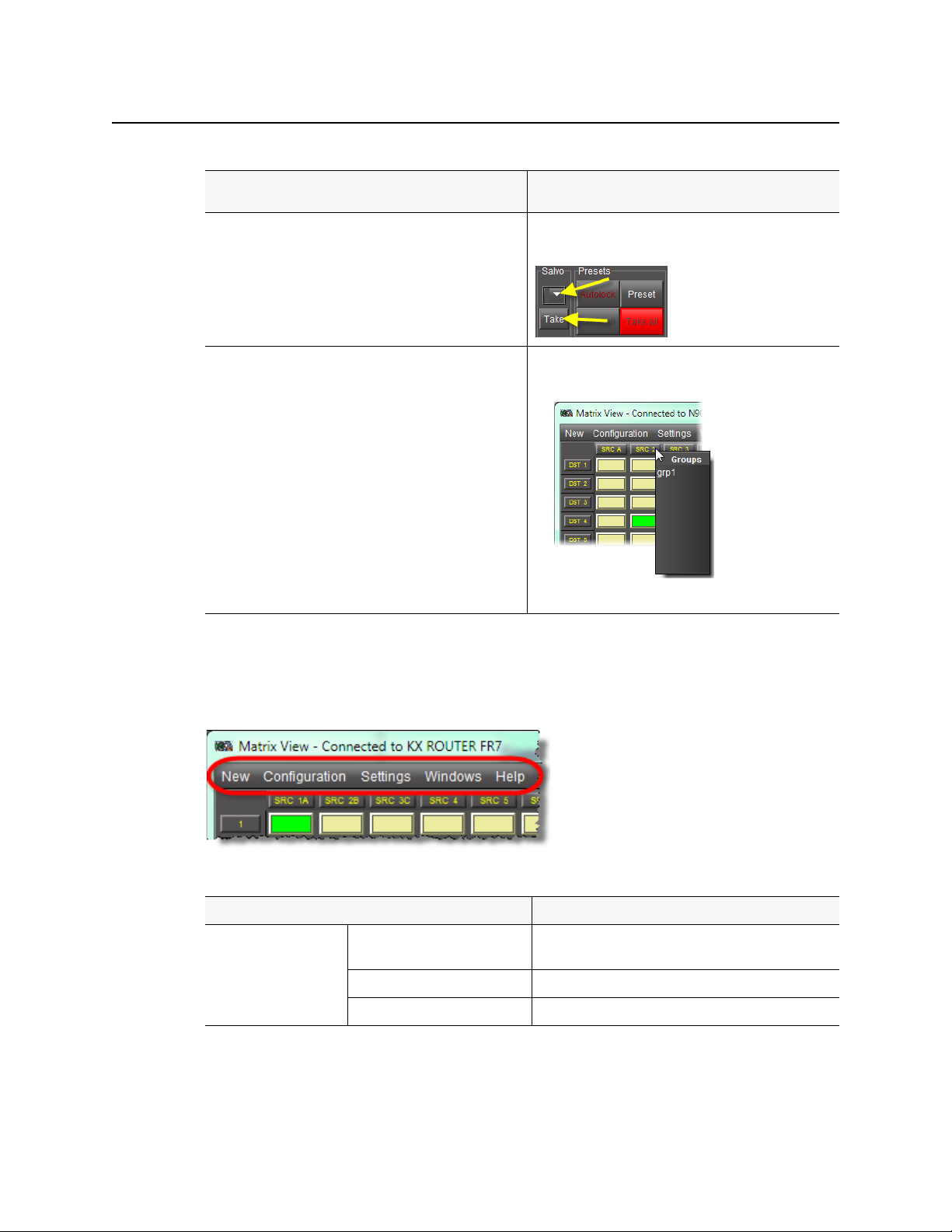
Matrix Menus
You may set some parameters of the Matrix View using the Matrix View menus located along
the top of the Matrix View window.
Matrix View menu items
Menu item Action
New Single Bus Opens a new Single bus window with destination 1
selected.
Matrix View Opens a new Matrix View window.
Status View Opens a window showing the router status.
5
Page 10
Operating Interface
Single Bus Window
Matrix View menu items (
Menu item Action
Configuration Salvo Editor Invokes the configuration mode Salvo editor window.
Settings Status Bar On Displays status bar.
Continued
Exclusion Editor Invokes the configuration mode Exclusion editor
Group Editor Invokes the configuration mode Group editor window.
Sound On Enables sound effects.
Header tip On Shows an enlarged version of the source and destination
Zoom Zoom In Makes matrix cells bigger. This is useful for big routers with
)
window.
Off Hides status bar.
Off Disables sound effects.
labels under the cursor tip, useful when the displayed
labels are very small, e.g. when zoomed out on a large
matrix
Off Disables the supplementary label display.
many levels.
Zoom Out Shrinks matrix cells in order to show as much of the matrix
as possible.
Windows Contains a list of open windows. Selecting an entry will
Close Closes current window. If the window is the last one open
Single Bus Window
Default Size Resizes matrix cells to the default size.
Fit horizontally Tries to fit all of the sources into the window.
bring it to the front.
– then exit.
6
Page 11
iControl Router
User Guide
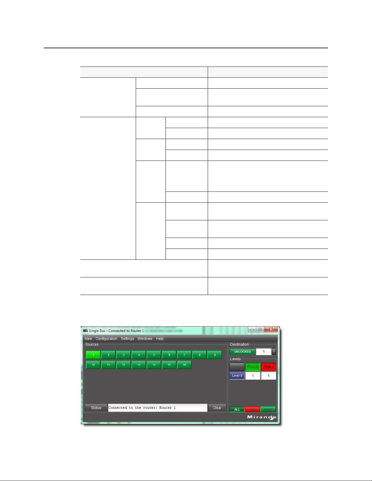
The Single Bus window shows sources on the left as a set of buttons, and destinations on the
right. Destinations appear in the list in the Destination area (either a single bus, or a group
with a defined name, or an Anonymous group created temporarily; the latter two from the
Destination/Group Selection window).
See also
For more information, see:
• "Single Bus Window Common Tasks" on page 7
• "Single Bus Menus" on page 9
• "Destination locks" on page 23
• "Opening the Single Bus Window" on page 27
Single Bus Window Common Tasks
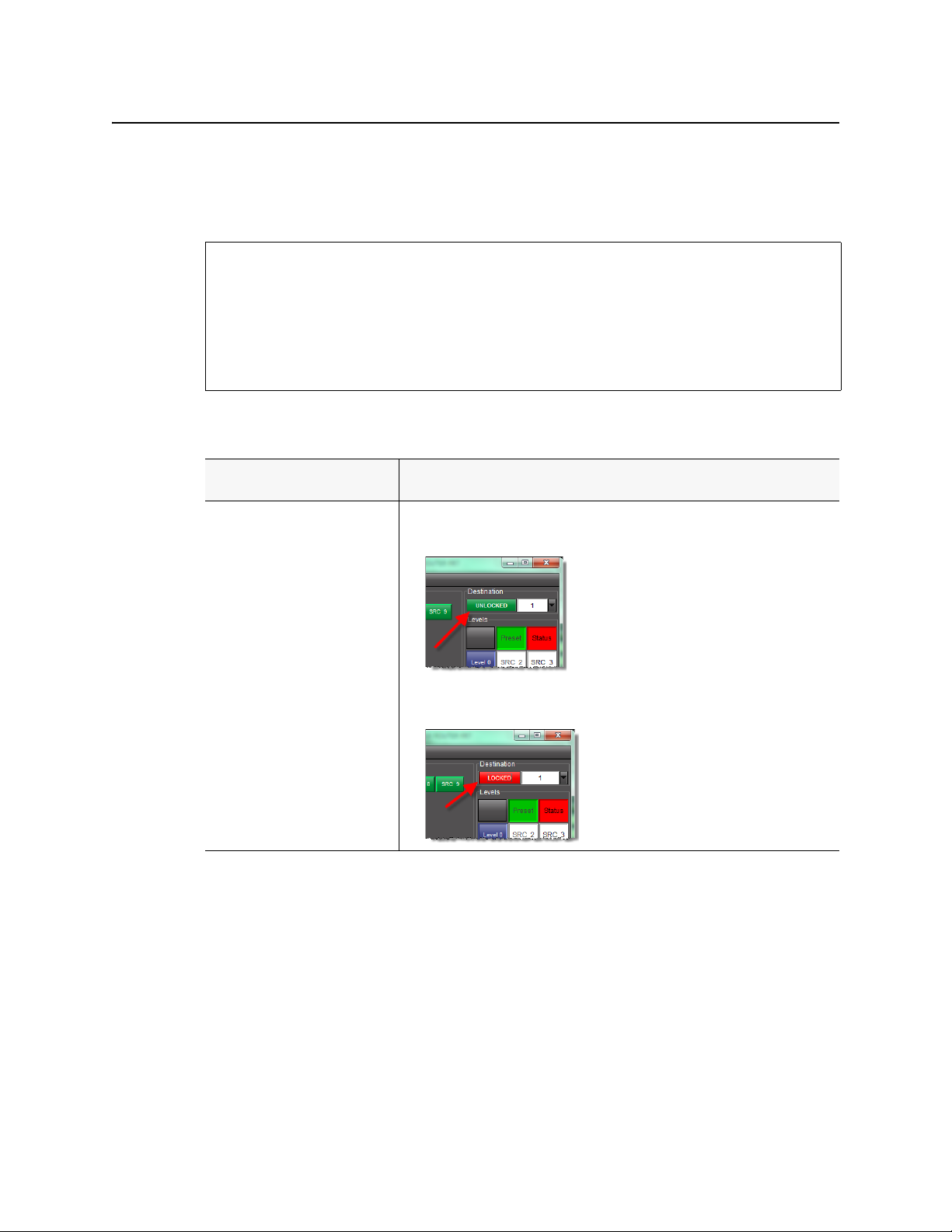
To do this... ...do this...
Cycle the selected destination
busses between locked and
unlocked states.
1
1. In the Destination area, in the row corresponding to the desired destination,
click the button so it displays UNLOCKED to effect an unlocked state.
2. Click the button so it displays LOCK ED to effect a locked state.
7
Page 12
Operating Interface
Single Bus Window Common Tasks
(
Continued
)
To do this... ...do this...
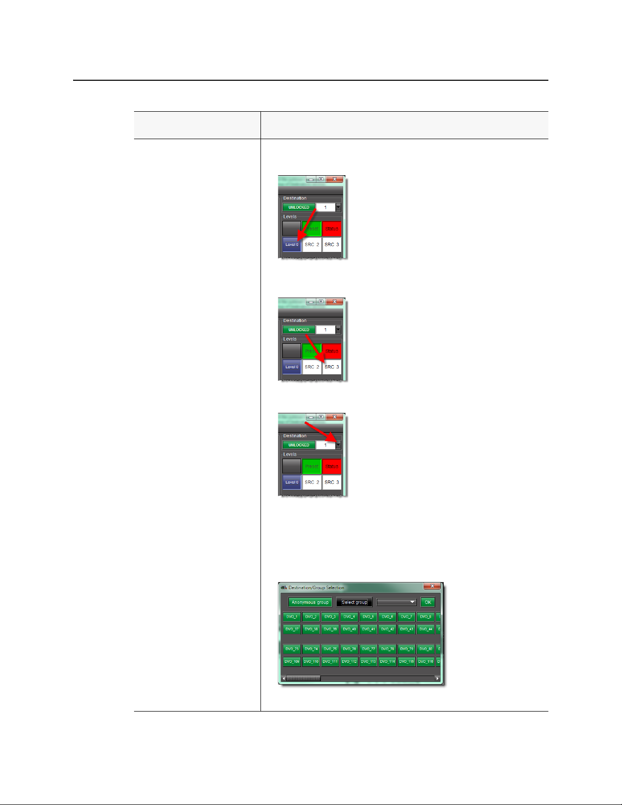
Select which levels are switched
1. In the Levels area, enable the buttons corresponding to all the levels for which
you would like to enable switching.
2. The current source at the output for each level is shown in the Status column.
Select one or more groups of
destinations
1. In the Destination area, click the Down arrow next to the list of destinations.
The Destination/Group Selection window appears.
2. If you would like to select a single destination, click the desired destination.
3. If you would like to select multiple destinations, click Select group, then either
select the desired destinations by click ing o n eac h of th em or click Select group
to select all of them.
2
4. Click OK.
8
Page 13
iControl Router
User Guide
1. If part of a group is locked, the overall group will be unlocked; those that are unlocked do not change
state.
2. If you would like to make this an anonymous group, click Anonymous group.
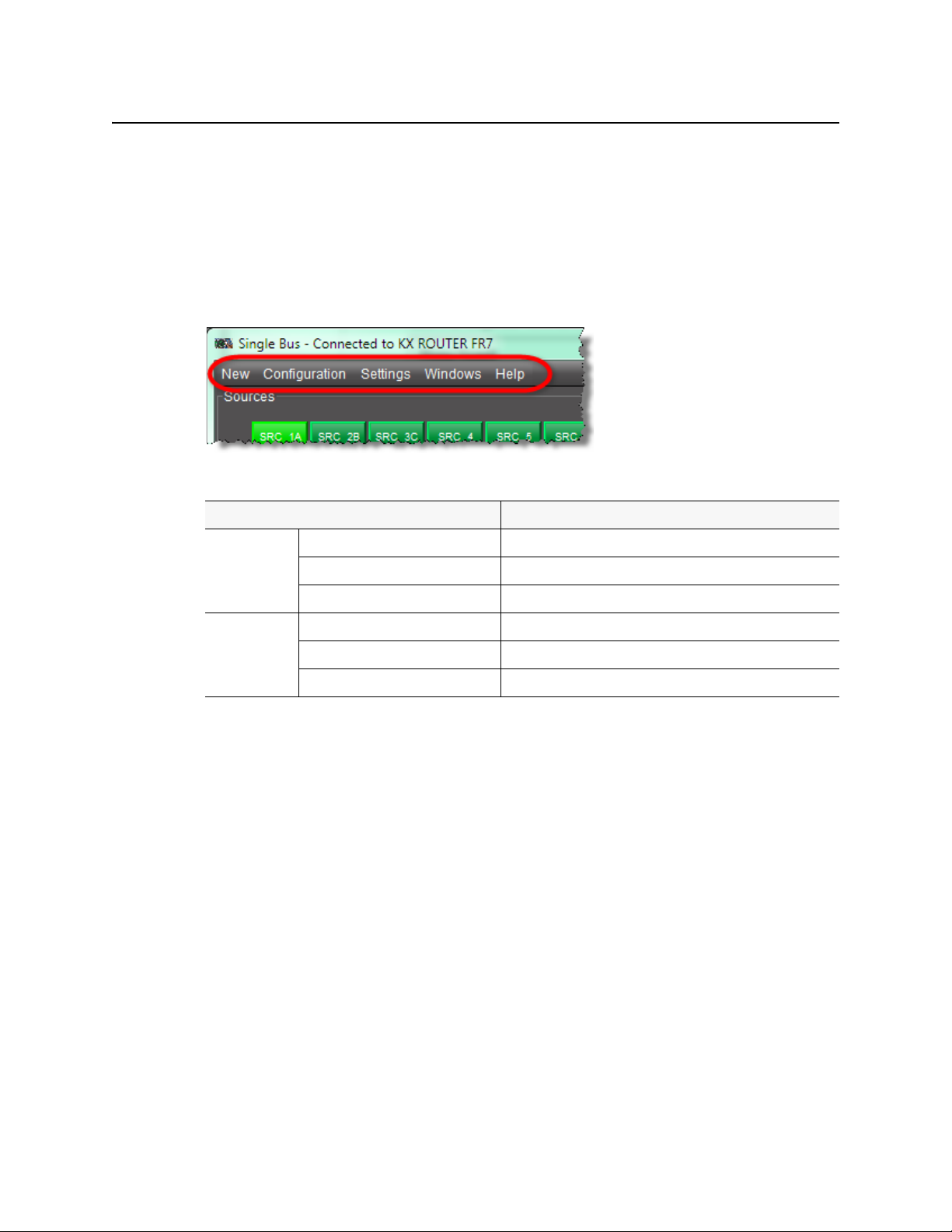
Single Bus Menus
You may set some parameters of the Single Bus window using the menus located along the
top.
Single Bus menu items
Menu item Action
New Single Bus Opens a new Single bus window with destination 1 selected.
Matrix View Opens a new Matrix View window.
Status View Opens a window showing the router status.
Configuration Salvo Editor Invokes the configuration mode Salvo editor window.
Exclusion Editor Invokes the configuration mode Exclusion editor window.
Group Editor Invokes the configuration mode Group editor window.
9
Page 14

Operating Interface
Single Bus Menus
Single Bus menu items (
Menu item Action
Settings Status Bar On Displays status bar.
Sound On Enables sound effects.
Autolock On Shows an enlarged version of the source and destination labels
Preset On Enables presets.
Chop
interval
Continued
Off Hides status bar.
Off Disables sound effects.
Off Disables the supplementary label display.
Off Disables presets.
No auto chopping Disables autochopping
Set chop interval to 0.5s Changes chop interval to 0.5 seconds
)
under the cursor tip, useful when the displayed labels are very
small
The new selection appears in the Preset area, and is set at the
output when the Tak e button is clicked. The take is inhibited if
any exclusions are violated, or if the selected destination is
locked.
The Preset area is dimmed. All selected outputs switch
immediately to the source selected on the button in the left
panel.
Set chop interval to 1s Changes chop interval to 1 second
Set chop interval to 1.5s Changes chop interval to 1.5 seconds
Set chop interval to 2s Changes chop interval to 2 seconds
Set chop interval to 2.5s Changes chop interval to 2.5 seconds
Set chop interval to 3s Changes chop interval to 3 seconds
Set chop interval to 10s Changes chop interval to 10 seconds
Set chop interval to 30s Changes chop interval to 30 seconds
Windows Contains a list of open windows. Selecting an entry will bring it
to the front.
Close Closes current window. If the window is the last one open – then
exit.
10
Page 15
Router Status Window
iControl Router
User Guide
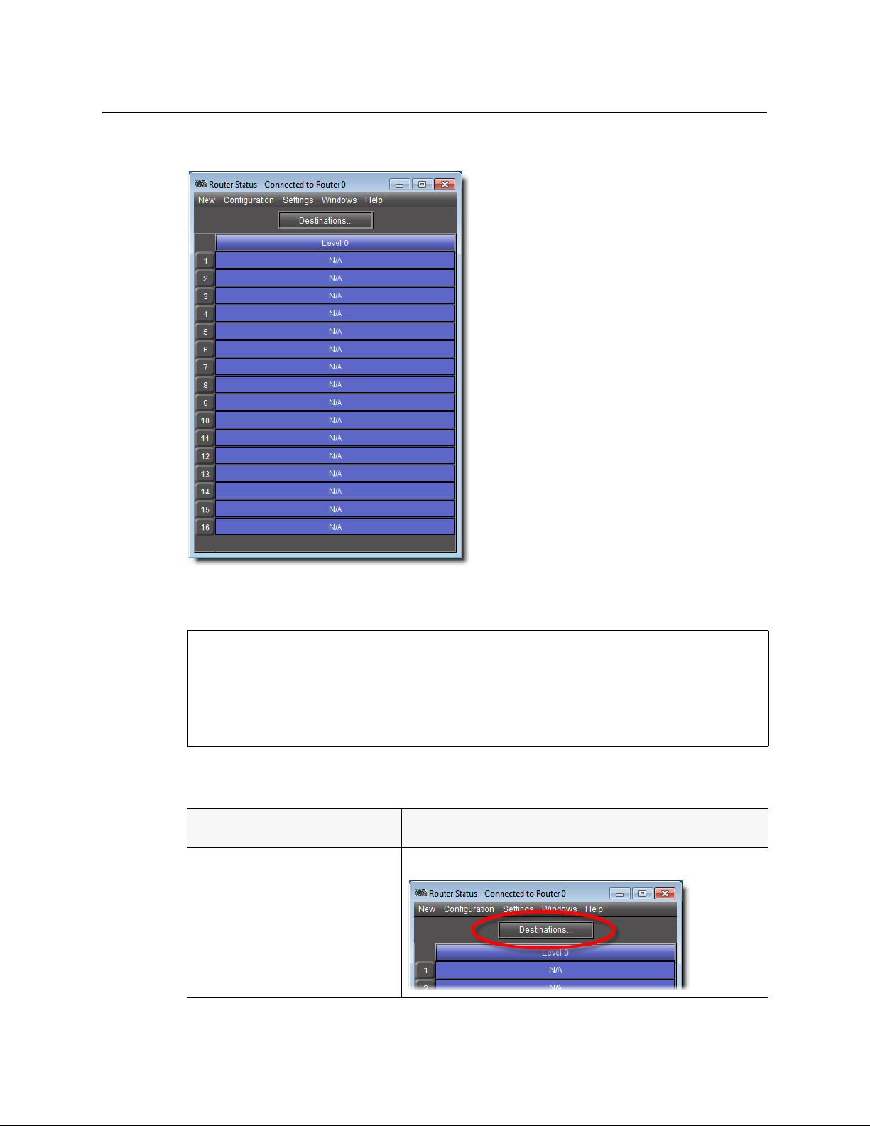
The Router Status window displays router status and labels of all destinations or groups of
destinations.
See also
For more information, see:
• "Router Status Window Common Tasks" on page 11
• "Router Status Menus" on page 12
• "Opening the Router Status Window" on page 29
Router Status Window Common Tasks
To do this... ...do this...
Display the Destination/Group Selection
window
Click Destinations.
11
Page 16
Operating Interface
Router Status Menus
(
Continued
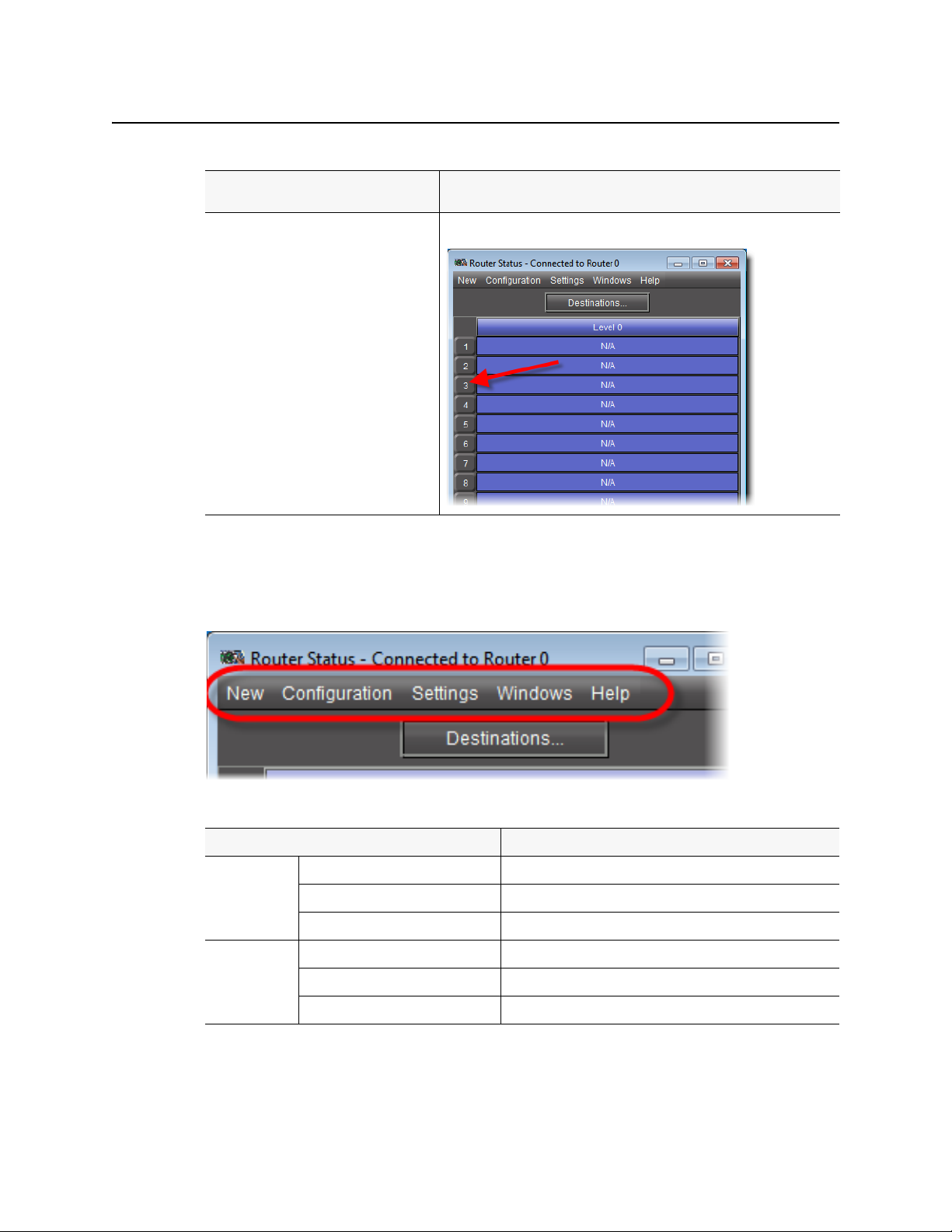
To do this... ...do this...
Display the Single Bus window Click the desired level.
)
Router Status Menus
You may set some parameters of the Single Bus window using the menus located along the
top.
Router Status menu items
Menu item Action
New Single Bus Opens a new Single bus window with destination 1 selected.
Matrix View Opens a new Matrix View window.
Status View Opens a window showing the router status.
Configuration Salvo Editor Invokes the configuration mode Salvo editor window.
Exclusion Editor Invokes the configuration mode Exclusion editor window.
Group Editor Invokes the configuration mode Group editor window.
12
Page 17
iControl Router
User Guide
Router Status menu items (
Menu item Action
Settings Status Bar On Displays status bar.
Windows Contains a list of open windows. Selecting an entry will bring it
Close Closes current window. If the window is the last one open – then
Exclusion Editor
Continued
Off Hides status bar.
Sound On Enables sound effects.
Off Disables sound effects.
)
to the front.
exit.
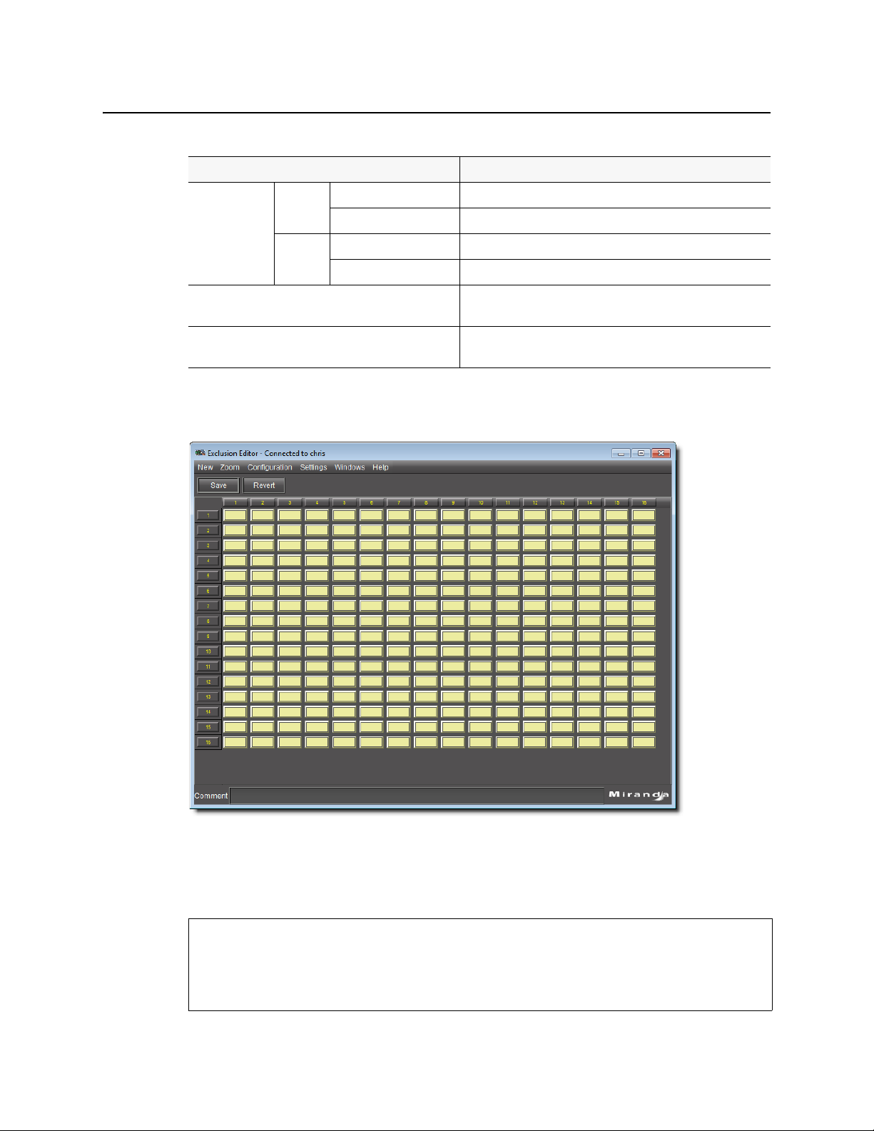
Exclusion Editor allows you to forbid user-specified router inputs from appearing on userspecified router outputs. Sources extend along the horizontal axis and are labeled across the
top of the matrix. Destinations extend along the vertical axis and are labeled down the left
side of the matrix.
See also
For more information, see:
• "Exclusion Editor Common Tasks" on page 14
• "Exclusion Editor Menus" on page 16
13
Page 18
Operating Interface
Exclusion Editor Common Tasks
See also (Continued)
For more information, see:
• "Opening Exclusion Editor" on page 30
Exclusion Editor Common Tasks
To do this... ...do this...
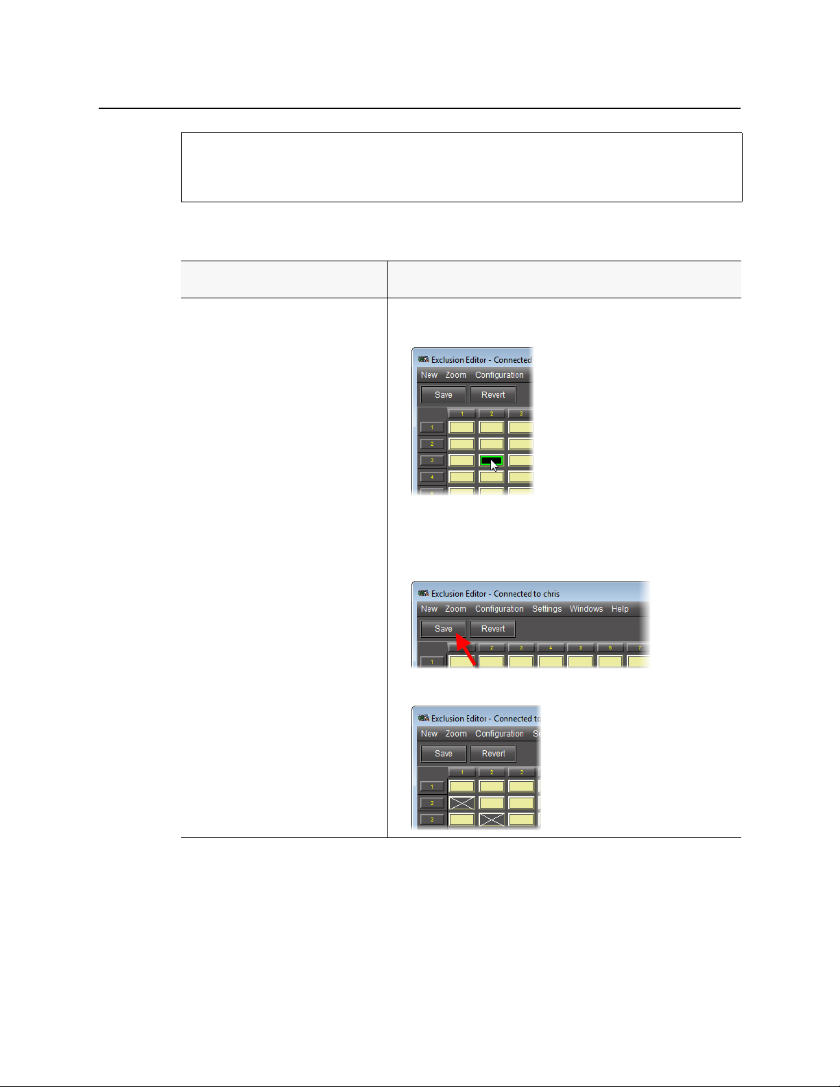
Configure an exclusion.
1. Click the box corresponding to the intersection of the source and
destination whose match you would like to exclude.
A green outline appears around the selected box. Do this for all desired
exclusions.
2. Click Save.
The selected boxes appear with a grey background and a white ×.
1
14
Page 19
iControl Router
(
Continued
)
To do this... ...do this...
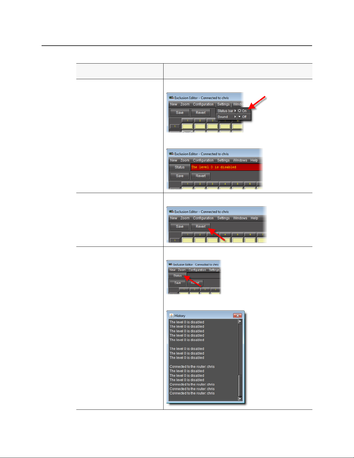
Display the Status bar. On the Settings menu, point to Status bar, and then select On.
The Status bar appears.
User Guide
Revert back to the last saved exclusion
settings.
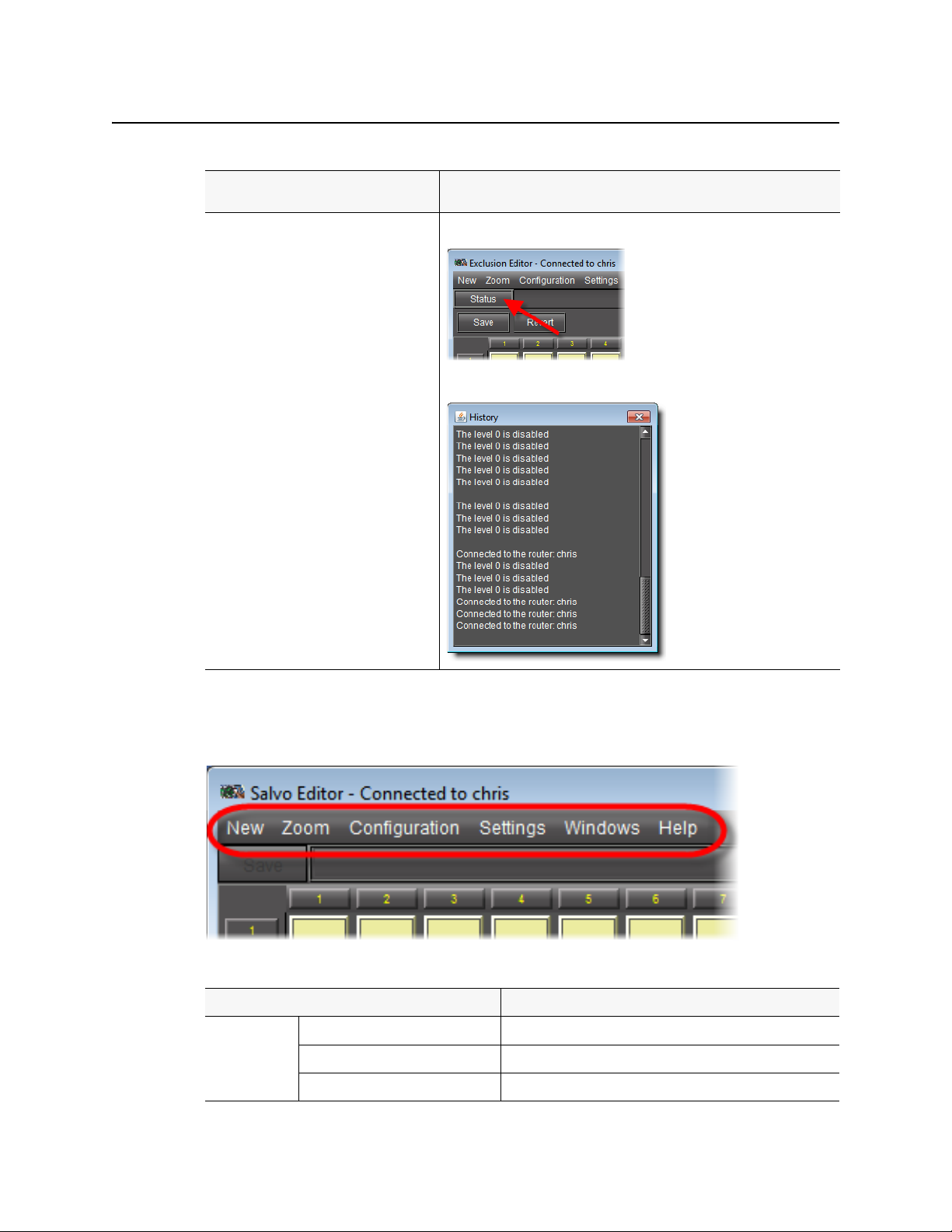
Display the status history log. Click Status.
Click Revert.
The History window appears.
15
Page 20
Operating Interface
Exclusion Editor Menus
1. If any exclusions are not allowed because of other choices made in the router definition, they will not
appear on the matrix. Additionally, a note will appear (highlighted in red) in the Status box at the top
of the pane. Click Status to see a list of all notes.
Exclusion Editor Menus
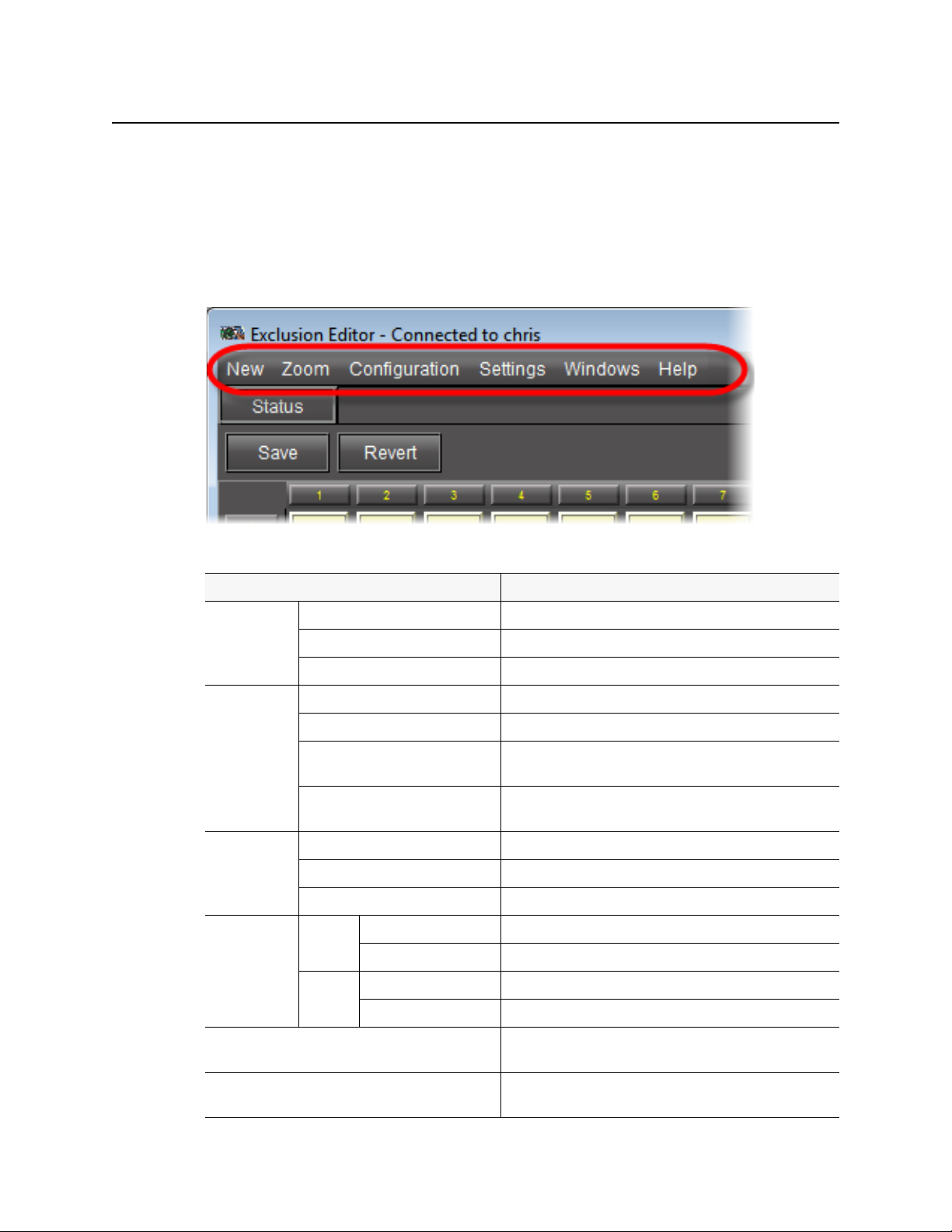
You may set some parameters of the Exclusion Editor using the menus located along the top.
Exclusion Editor menu items
Menu item Action
New Single Bus Opens a new Single bus window with destination 1 selected.
Matrix View Opens a new Matrix View window.
Status View Opens a window showing the router status.
Zoom Zoom in Magnifies the view of the matrix by a set increment.
Zoom out Demagnifies the view of the matrix by a set increment.
Default size Reverts the magnification of the matrix to the default zoom
setting.
Fit horizontally Magnifies or demagnifies the view of the matrix so that it fits
horizontally within the Exclusion Editor’s win dow.
Configuration Salvo Editor Invokes the configuration mode Salvo editor window.
Exclusion Editor Invokes the configuration mode Exclusion editor window.
Group Editor Invokes the configuration mode Group editor window.
Settings Status Bar On Displays status bar.
Off Hides status bar.
Sound On Enables sound effects.
16
Off Disables sound effects.
Windows Contains a list of open windows. Selecting an entry will bring it
to the front.
Close Closes current window. If the window is the last one open – then
exit.
Page 21
Salvo Editor
iControl Router
User Guide
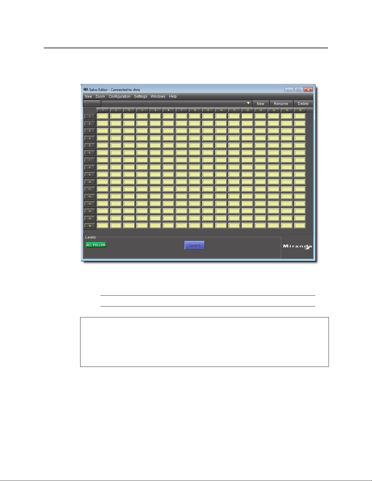
Salvo Editor allows you to create and name a configuration of crosspoint closures. Individual
levels may be specified at each crosspoint or the entire group may be specified.
Note: Exclusions are shown on the matrix and cannot be overridden.
See also
For more information, see:
• "Salvo Editor Common Tasks" on page 18
• "Salvo Editor Menus" on page 19
• "Opening Salvo Editor" on page 30
17
Page 22
Operating Interface
Salvo Editor Common Tasks
Salvo Editor Common Tasks
To do this... ...do this...
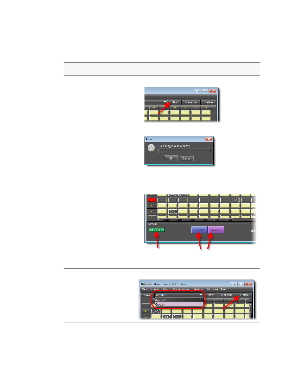
Create a salvo of crosspoint closures.
1. Click New.
The Input window appears.
2. Type a name for this salvo and then click OK.
3. Select one or more levels at the bottom of the window, or else click ALL
FOLLOW, to associate this salvo with the desired levels.
4. Click all crosspoints you would like to include in this salvo.
5. Click Save.
Delete a salvo. Select the salvo you would like to delete from the list, and then click Delete.
18
Page 23
(
Continued
)
To do this... ...do this...
Display the status history log. Click Status.
The History window appears.
iControl Router
User Guide
Salvo Editor Menus
You may set some parameters of the Salvo Editor using the menus located along the top.
Salvo Editor menu items
Menu item Action
New Single Bus Opens a new Single bus window with destination 1 selected.
Matrix View Opens a new Matrix View window.
Status View Opens a window showing the router status.
19
Page 24
Operating Interface
Groups Editor
Salvo Editor menu items (
Menu item Action
Zoom Zoom in Magnifies the view of the matrix by a set increment.
Zoom out Demagnifies the view of the matrix by a set increment.
Default size Reverts the magnification of the matrix to the default zoom
Fit horizontally Magnifies or demagnifies the view of the matrix so that it fits
Configuration Salvo Editor Invokes the configuration mode Salvo editor window.
Exclusion Editor Invokes the configuration mode Exclusion editor window.
Group Editor Invokes the configuration mode Group editor window.
Settings Status Bar On Displays status bar.
Sound On Enables sound effects.
Windows Contains a list of open windows. Selecting an entry will bring it
Close Closes current window. If the window is the last one open – then
Continued
Off Hides status bar.
Off Disables sound effects.
)
setting.
horizontally within the Exclusion Editor’s win dow.
to the front.
exit.
Groups Editor
Groups Editor allows you to create and edit groupings of destinations.
See also
For more information, see:
• "Groups Editor Common Tasks" on page 21
• "Groups Editor Menus" on page 22
20
Page 25
See also (Continued)
For more information, see:
• "Opening Groups Editor" on page 31
Groups Editor Common Tasks
To do this... ...do this...
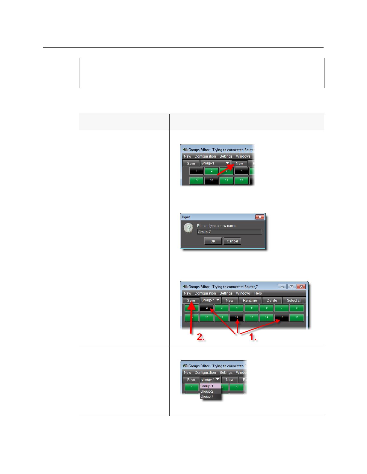
Create a group.
1. Click New.
An Input window appears.
2. Type a name for the new group, and then click OK.
iControl Router
User Guide
Edit a group.
3. In the matrix, select the destinations buttons you would like to include
in this group, and then click Save.
1. Select the group you would like to edit in the group list.
2. Change the button selection for this group, and then click Save.
21
Page 26
Operating Interface
Groups Editor Menus
(
Continued
To do this... ...do this...
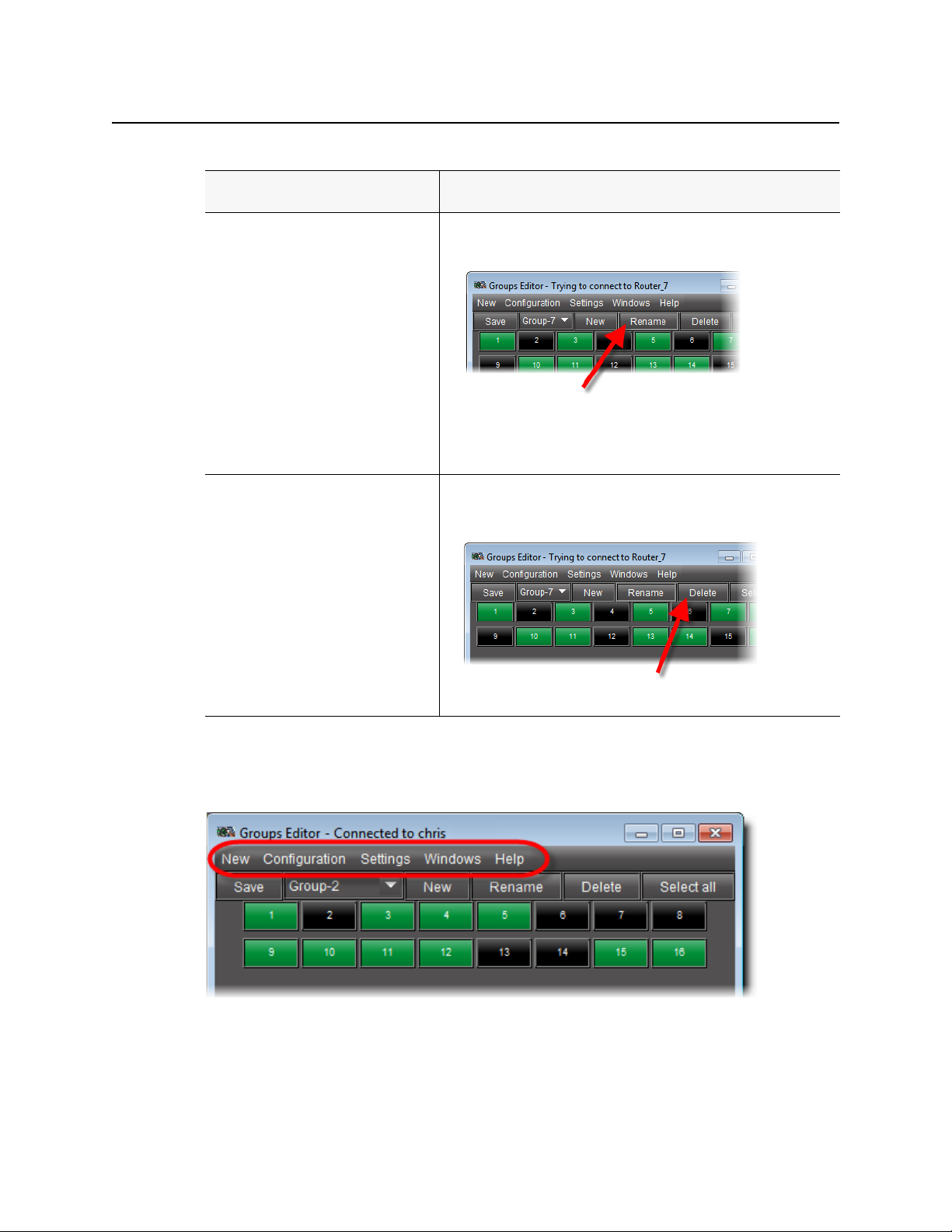
Rename a group.
Delete a group.
)
1. Select the group whose name you would like to change in the group list.
2. Click Rename.
The Input window appears.
3. Type a new name for this group, and then click OK.
4. Click Save.
• Select the group you would like to delete from the group list.
•Click Delete.
The group disappears from the group list.
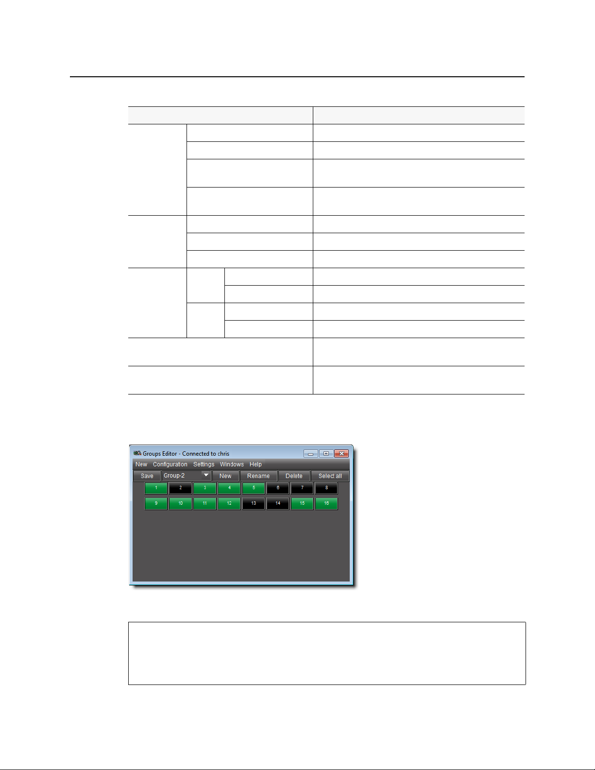
Groups Editor Menus
You may set some parameters of the Exclusion Editor using the menus located along the top.
22
Page 27
iControl Router
User Guide
Groups Editor menu items
Menu item Action
New Single Bus Opens a new Single bus window with destination 1 selected.
Matrix View Opens a new Matrix View window.
Status View Opens a window showing the router status.
Configuration Salvo Editor Invokes the configuration mode Salvo editor window.
Exclusion Editor Invokes the configuration mode Exclusion editor window.
Groups Editor Invokes the configuration mode Group editor window.
Settings Status Bar On Displays status bar.
Off Hides status bar.
Sound On Enables sound effects.
Off Disables sound effects.
Windows Contains a list of open windows. Selecting an entry will bring it
to the front.
Close Closes current window. If the window is the last one open – then
Destination locks
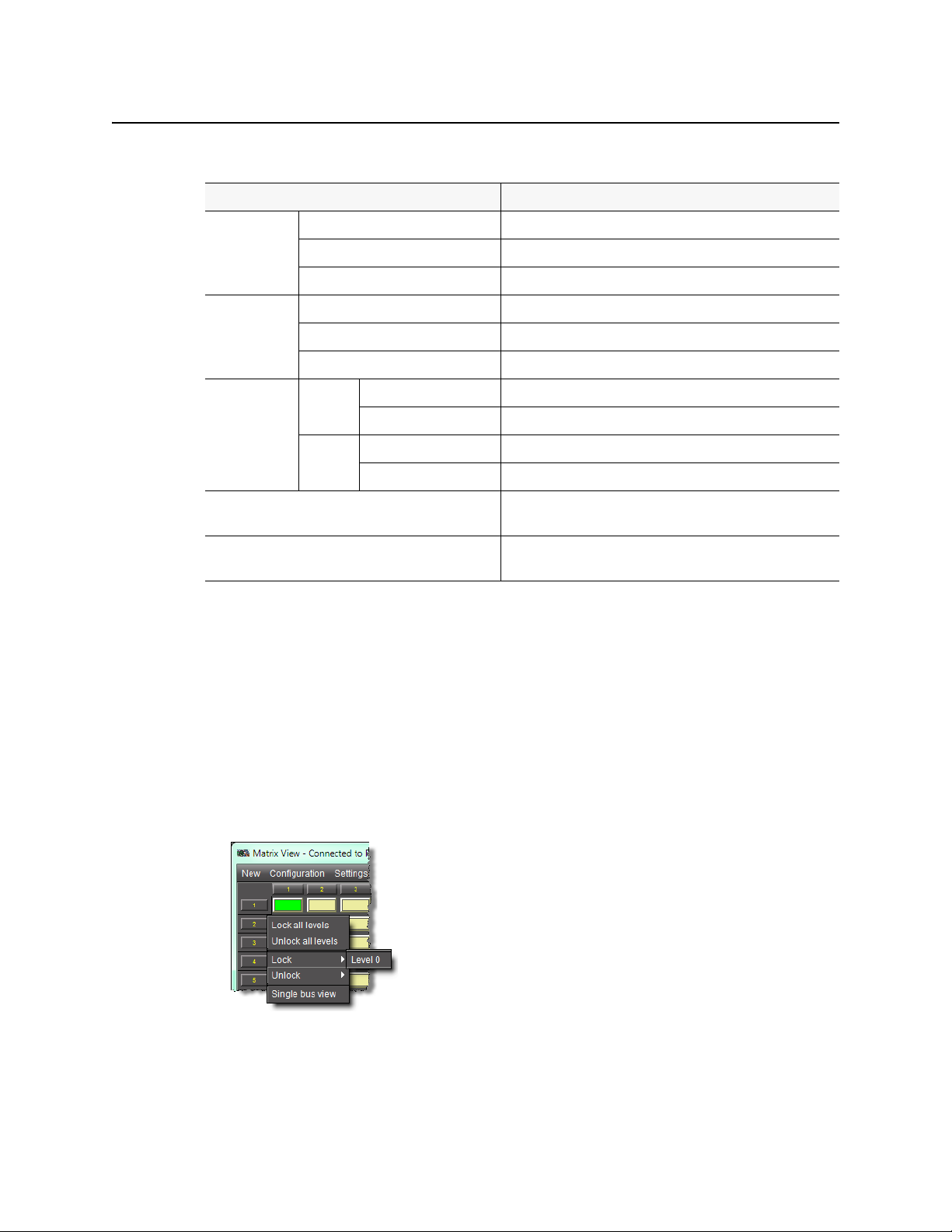
The settings in the Matrix View window may be locked, and when locked, they cannot be
changed until the lock is removed. Locked selections appear red on the screen. The crosspoint,
and also the row (destination) label on the left is red. Locking can occur in two ways:
• Clicking on the row label box at the left of the screen opens a window which allows levels
in that row to be locked. Options are: Lock all levels, Unlock all levels, Lock (with a
subsidiary menu listing all currently unlocked levels in that row), and Unlock (with a
subsidiary menu listing all currently locked levels in that row). The Single Bus View option
is also found in this menu.
exit.
•If Autolock is selected in the Preset area, then any change which is taken, in either PRESET
or TAKE mode, is automatically locked on all levels...
23
Page 28
Operating Interface
Detailed Directions
Note: Locking occurs immediately; the TAKE/PRESET rules do not apply.
Detailed Directions
Opening the Matrix View
See also
For more information about the Matrix View, see page 3.
Opening a New Matrix View from iControl
Perform this procedure if you would like to open a new Matrix View from iControl.
REQUIREMENT
Before beginning this procedure, make sure you have opened iControl.
To open a new Matrix View from iControl
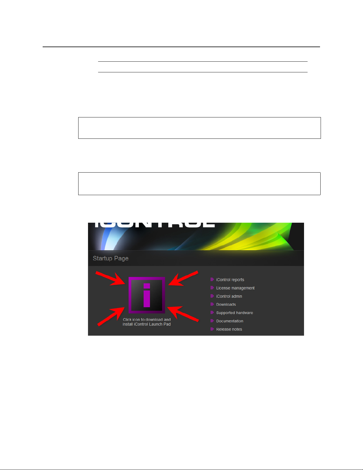
1. On the
The iControl Launch Pad executable file is downloaded to your local file system.
2. Double-click the executable file.
iControl Launch Pad appears.
3. On iControl Launch Pad, either type in the IP address of your Application Server or select
from the list of available IP addresses.
iControl—Startup page, click the massive i icon.
24
Page 29
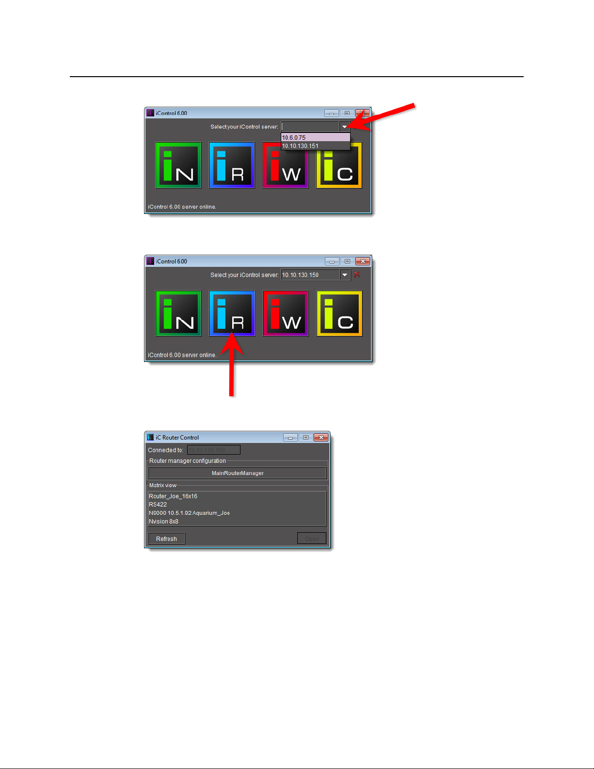
4. Click the iC Router Control icon.
iControl Router
User Guide
The iC Router Control window appears.
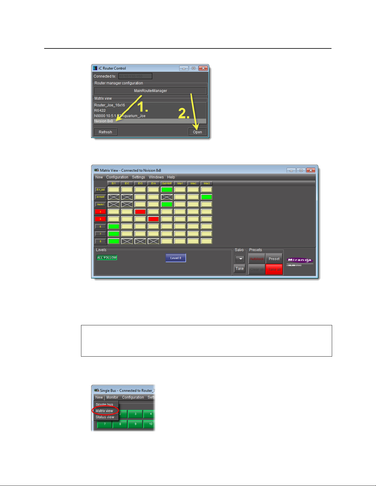
5. In the iC Router Control window, in the Matrix view area, select the router you wish to
view.
6. Click Open.
25
Page 30
Operating Interface
Opening a New Matrix View from Another Operational Window
The Matrix View window for the selected router appears.
26
Opening a New Matrix View from Another Operational Window
Perform this procedure to open a new Matrix View from a Single Bus window.
REQUIREMENT
Before beginning this procedure, make sure you have open either a Single Bus window or
a Router Status window, each associated with the desired router (see page 24).
To open a new Matrix View
•In the Single Bus window, on the New menu, click Matrix view.
Page 31

iControl Router
User Guide
Toggling to a Matrix View from Another Operational Window
Perform this procedure to toggle to an existing Matrix View from another iControl Router
window.
REQUIREMENTS
Make sure you meet the following conditions before beginning this procedure:
• You have a Single Bus window open and in focus (each associated with the appropriate
router).
•A Matrix View for the appropriate router is open.
To toggle focus to an existing Matrix View
•In a Single Bus window, on the Window menu, click the desired Matrix View selection.
Opening the Single Bus Window
See also
For more information about the Single Bus window, see page 6.
Opening the Single Bus Window
REQUIREMENT
Before beginning this procedure, make sure you have opened the Matrix View associated
with the appropriate router (see page 24).
To open the Single Bus window
•In the Matrix View, on the New menu, click Single bus.
Alternatively, in the case where you are beginning from the Router Status window, you
may also click the router level corresponding to the appropriate source.
27
Page 32

Operating Interface
Toggling to a Single Bus Window from Another Operational Window
Note: Choosing this second option opens the Single Bus window with the source
you selected in the Router Status window pre-selected.
Toggling to a Single Bus Window from Another Operational Window
Perform this procedure to toggle to an existing Single Bus window from another iControl
Router window.
REQUIREMENTS
Make sure you meet the following conditions before beginning this procedure:
• You have either a Matrix View or a Router Status window open and in focus (each
associated with the appropriate router).
•A Single Bus window for the appropriate router is open.
To toggle focus to an existing Single Bus window
• In either a Matrix View or a Router Status window, on the Window menu, click the desired
Single Bus selection.
28
Page 33

Opening the Router Status Window
See also
For more information about the Router Status window, see page 11.
Opening a New Router Status Window
Perform this procedure to open a new Router Status window from either the Single Bus
window or the Matrix View.
REQUIREMENT
Before beginning this procedure, make sure you have open either a Single Bus window or
a Matrix View, each associated with the desired router (see page 24).
To open a new Router Status window
• In either the Single Bus window or the Matrix View, on the New menu, click Status view.
iControl Router
User Guide
Toggling to a Router Status Window from Another Operational Window
Perform this procedure to toggle to an existing Router Status window from another iControl
Router window.
REQUIREMENTS
Make sure you meet the following conditions before beginning this procedure:
• You have either a Single Bus window or a Matrix View open and in focus (each
associated with the appropriate router).
•A Router Status window for the appropriate router is open.
To toggle focus to an existing Router Status window
•In either a Single Bus window or a Matrix View, on the Window menu, click the desired
Router Status selection.
29
Page 34

Operating Interface
Opening Salvo Editor
Opening Salvo Editor
See also
For more information about Salvo Editor, see page 17.
REQUIREMENT
Before beginning this procedure, make sure you have open and in focus ONE of the
following windows:, each associated with the appropriate router
• Router Status window
• Matrix View
• Single Bus window
To open Salvo Editor
• In one of Router Status, Matrix View, or the Single Bus windows, on the Configuration
menu, click Salvo editor.
Opening Exclusion Editor
See also
For more information about Exclusion Editor, see page 13.
REQUIREMENT
Before beginning this procedure, make sure you have open and in focus ONE of the
following windows:, each associated with the appropriate router
• Router Status window
• Matrix View
• Single Bus window
To open Exclusion Editor
• In one of Router Status, Matrix View, or the Single Bus windows, on the Configuration
menu, click Exclusion editor.
30
Page 35

Opening Groups Editor
See also
For more information about Groups Editor, see page 20.
REQUIREMENT
Before beginning this procedure, make sure you have open and in focus ONE of the
following windows:, each associated with the appropriate router
• Router Status window
• Matrix View
• Single Bus window
iControl Router
User Guide
To open Groups Editor
• In one of Router Status, Matrix View, or Single Bus wi nd ows , o n the Configuration menu,
click Group editor.
31
Page 36

Operating Interface
Opening Groups Editor
32
Page 37

General
Routing Switchers Tips and Tricks
The current version of Miranda’s Router Control Software supports serial, TCP/IP, and UDP/IP
communications connections. There are several general considerations regarding routing
switcher configuration.
If there is a choice between an RS-232 port and an RS-422 port, preference should be given to
the RS-232 port in order to avoid cabling problems. If RS-422 is used be careful of the pinouts
– please check thoroughly.
If the router can be configured to operate at different baud rates, in most cases the fastest
setting should be used, unless a recommended baud rate is specified in your router’s manual
or in this document.
If the software cannot detect the levels, then it is necessary to attach a standard PC through a
serial port, run HyperTerminal, switch some crosspoints from a physical control panel and
check if there is any communication over the serial port. In some cases it is necessary to enable
reporting over the serial port.
Nevion
Network Compact Protocol (Default Driver for VikinX Compact Routers)
Every VikinX Compact router is equipped with a RS-232 port. Although the panels are
equipped with the port as well, it is not recommended to use it. It is possible to use a standard
1
straight-through
rate 19200, but there are certain exceptions, so it is necessary to check the manual for your
particular model. Other port settings are 8 bits, no parity, 1 stop bit, and no flow control. The
DIP switches on the back of the router and the frame type define the address of the frame.
Type the value set by the DIP switches in the Frame ID box when you define your levels in
Miranda’s Router Control Software.
The Network protocol supports two types of frames: video and audio. Telecom routers act like
a video frame and the RS-422 Data router can be configured by DIP switches to work either as
video or as audio. Please refer to your device’s user manual for more information.
Troubleshooting
The Network Compact protocol is a binary protocol. For each crosspoint on each level the
router sends 3 bytes to the serial port. It means that you will see some kind of pseudographics
in your HyperTerminal window.
1. A double cross-over should also work.
modem cable with a gender-bender. Most of the routers are using baud
Page 38
Routing Switchers Tips and Tricks
Network Modular Protocol (Control Protocol for VikinX Modular Routers)
Network Modular Protocol (Control Protocol for VikinX Modular Routers)
Please refer to the following document for more information about this protocol:
\\ca-ops-data\Groups\RD
Software\Documentation\iControlRouter\Protocols\Network\VikinX_Control_Protoco
l_rev3.pdf
Select this driver if you wish to use a router controller such as your VikinX Modular router's
SysCon card or an external ETH-CON device.
The Network Modular protocol is an Ethernet ASCII protocol, and uses port 4381.
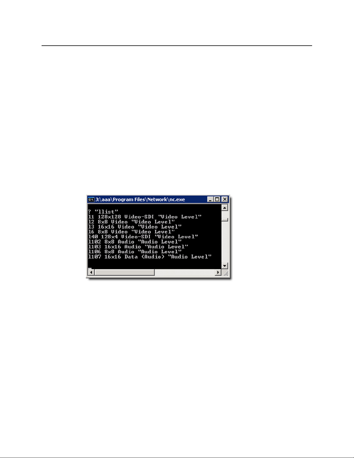
To confirm the router controller is properly configured
1. Connect to the controller using telnet.
2. In a telnet session, type:
llist
3. Hit
Enter
twice.
The response will be something like this:
34
4. To get the status of all the crosspoints on a level, type
twice.
The response will have the following form:
x l<level> <src> <dest>
s l<level>, and then press
Enter
Page 39

iControl Router
User Guide
Leitch
5. You can also switch crosspoints, by typing x l<level> <src> <dest>, and then pressing
Enter
twice.
You will get a confirmation like this:
The software supports the Leitch ASCII Passthrough protocol. The application server can be
connected to the Leitch system either directly or via an SPT (Serial Protocol Translator). The
serial port on the SPT can be configured to act either as a RS-232 or RS-422 port using jumpers
located under the cover of the box (see the manufacturer’s manual). When using the 232
ports, it is necessary to use a null-modem cable. DIP switches located under the cover of SPT
can be used to configure the baud rate. The other parameters are 8 bits, no parity, 1 stop bit,
and no flow control. Some old versions of the SPT had a bug in the firmware that prevented
35
Page 40

Routing Switchers Tips and Tricks
Troubleshooting
them from responding correctly. Leitch can replace the firmware chip and it may be best to
upgrade to the latest firmware version in any case.
IMPORTANT: The echo mode MUST be ON for the driver to work properly. If the echo mode is
off, you may not be able to switch crosspoints.
To support the Leitch protocol on TCP/IP, a login/password must be set. By default, the driver
login=leitch and password=leitchadmin. To change the login/password values, add
uses
the following two lines:
DEF_OPTIONS=" ${DEF_OPTIONS} Dcom.miranda.icontrol.routers.leitch.login=leitch"
DEF_OPTIONS=" ${DEF_OPTIONS} Dcom.miranda.icontrol.routers.leitch.password=leitchadmin"
Troubleshooting
Leitch routers are using ASCII protocol to communicate with the router. In case of successful
connection hitting
<ENTER>
enable reporting type
its status back to the serial port.
to display the menu. To enable echo on the terminal type
<ENTER>
@<SPACE>?
will bring you to the command prompt (the > character). Press
T <space> O <ENTER>
. Once you enabled reporting the router will send changes in
. To
Q
Note: Do not type
reset the router. If you do you will have to upload the configuration using the Leitch
RouterMapper software.
Z<ENTER>
at the command prompt unless you really want to
How to get Firmware Version Number?
From the Leitch shell, type SHOW RPARM followed by <
ENTER
>.
Utah Scientific RCP-3 (SC-4 Controller Ethernet Only)
The RCP-3 protocol is supported by the following controller: UTAH-200, SC-3 and SC-4.
However, the driver only works with SC-4 controllers using an Ethernet connection. The SC-4
does not support RCP-3 serial protocol at this time.
When configuring the physical setting of the SC-4 in the Router Manager Configurator, you
must use the IP address of the System Controller with Port 5001.
The driver supports automatic labels and this means it will fetch them from the SC-4 controller
when it starts. To get them displayed in iControl and iRouter applications, you must set the
Auto update labels feature to ON in the configuration of the associated logical router in the
Router Manager Configurator.
36
Page 41

Utah Scientific RCP-1 (SC-3 Controller)
For Utah routers we support the SC-3 controller and the RCP-1 (ASCII) protocol. Sometimes
this protocol is referred as a UDI protocol. The software will not work with the SC-2 controller
because the RCP-1 is not fully implemented for that controller but It will probably work with
the UDI-1B converting panel. The ports for SC-3 can be configured to work as 422 or 232. In
the case of 232, it is necessary to use a null-modem cable with a gender-bender. During
configuration it is necessary to bind the UDI protocol to this port. Binding can be done either
from the Utah’s RMS software or via diagnostics serial port. The recommended port settings
are:
iControl Router
User Guide
Baud rate is 38400
•
• 8 bits
• No parity
• 1 stop bit
• No flow control
When configuring the port it is necessary to turn off the Matrix Refresh Report mode. The
Matrix Change Report and Matrix Take Report modes can be set to on, although it is optional
because the software turns them on automatically. When using the RMS for configuration of
the router, it is necessary to add the CSP table even when no CSP devices present. The
diagnostics port is a RS-232 port with DTE pinouts and fixed parameters:
• 38400 baud
• 8 data bits
• No parity
• 1 stop bit
37
Page 42

Routing Switchers Tips and Tricks
Troubleshooting
Troubleshooting
Utah routers are using semi-ASCII protocol to communicate over serial port. Semi-ASCII means
that in some cases it uses binary characters while for most purposes it uses normal ASCII. Note
that all the commands are case sensitive. Here is the list of the commands that can be used
during troubleshooting:
• Matrix Refresh Report. In this mode the controller will periodically (~5 sec) send the status
of the router to the serial port. Typically should be disabled.
• To enable this mode type
• To disable this mode type
• Matrix Change Report. In this mode the controller will notify the serial port about changes
in the router status. Typically should be enabled.
<Ctrl-[>@
<Ctrl-[>A
• To enable this mode type
• To disable this mode type
<Ctrl-[>B
<Ctrl-[>C
The characters you’re typing will not be visible at the command prompt.The status updates
have the format:
<SOH><Level 0-3><Level 4-7><Input><Output><CR>
where SOH is ASCII character with code 1, selected levels are represented with characters from
@ (no levels) to O (all levels), input and output are represented as three digits. For example, for
destination 5 levels 0 and 1 switched to source 7 will produce :
<SOH>B@007007<CR>
Notes
•The <
• One can experience delays when receiving response from the router after a
CR
> character (
crosspoint command. As a result it will execute a take of the last crosspoint
that was sent from that port. If no crosspoints were set before it will take bus
0 to source 0 on all available levels. Be careful!
crosspoint is taken. The delay can be 1-2 seconds. The crosspoint itself is
taken immediately. This behavior was noticed when running the software on
Linux while on Windows it works fine.
Enter
) is interpreted by the SC-3 as the end of set
Utah Scientific AVS
This router is a predecessor of CS-3 series. The router is equipped with one 232 port (25 pin),
one configurable 232/422 port (9 pin), one 422 port (9 pin) and one diagnostics RS 232 port.
All the tests were done on the RS-232 port. To connect to a 232 port you will need a standard
RS-232 cable with gender-bender on the router side. To connect to the diagnostics port you
will need a null-modem RS-232 cable. The baud rates are set on the controller board using DIP
switches. The other parameters can be set from the diagnostics port. As mentioned, this is very
old and slow protocol.
38
Page 43

Troubleshooting
iControl Router
User Guide
Philips
The easiest way to check the connection between the router and the server is to issue a
[>@
command that will switch the router refresh mode. In this case the router will periodically
send its status to the service. To disable this mode type
a <Ctrl-[>A
on a HyperTerminal.
<Ctrl-
The software was tested with the Jupiter VM-3000 controller. Although the controller supports
several different protocols, the RCS software implements only the ASCII protocol. The
controller has 8 configurable serial ports. It is necessary to configure one of the ports to work
with the ASCII protocol. That procedure is described in the Jupiter manual. The only trick is
configuration of the input and output sets. Inputs and outputs should be numbered starting
from 0 and there should be no gaps in numbering.
When specifying the Frame ID value in the RCS Configurator please note that in the case of
Jupiter the levels are numbered from 1 to 8. Although the ports on the controller are RS-422
ports, it is possible to create a cheater cable to connect to a RS-232 port on the Application
server. The wiring pinout can be found in the Jupiter manual in the section Connecting to a PC.
Please note that the serial port uses software (XON/XOFF) flow control.
Notes
• It is possible to use the probe port on the controller for diagnostics. But it is
necessary to keep in mind that sending the
HyperTerminal will short the pins on the port and will cause reboot of the
controller.
hang-up command from the
• It is possible to telnet to the controller. This will provide exactly the same info
as you can see on the probe port. It is necessary to send the
before disconnecting. There can be only one telnet session at a time.
• For testing purposes it is possible to use the controller without any routers. In
this case it is necessary to type the command
command prompt at the terminal or telnet.
• Use an RS-422 null modem cable between the Kaleido-X and the Philips
router
• On the Philips configuration side, there is a user define output set file which
needs to be create. In this output set file, customer needs to provide the
names for all outputs which are connected to the Kaleido-X. As for example:
the file display.out is created with the list of Prog1, Prog2,…,Prog n. Then the
file of switcher output will be use to know which physical output bus are
matching the Prog1, Prog2…, Prog n.
• In iControl Router Configurator (Router Manager), in logical router mapping
for output section, instead of using the physical output bus number, we
should have the output bus numbers ranging from 1 to n (where n is the
number of connections between Philips router outputs to Kaleido-X inputs)
_confirmAll=1 at the
bye command
39
Page 44

Routing Switchers Tips and Tricks
Troubleshooting
Troubleshooting
To start watching the changes in the status it is necessary to send the ZW999<CR> command.
The status report has the form of ZSOOOIIILLLLLLLL<CR> where OOO specifies the destination,
III specifies source and L specifies level. For example, destination 7 set to source 21 on levels 1
and 5 will produce status report
Digipath
The Digipath router is equipped both with RS-232 and RS-422 ports. In order to connect to the
RS-232 port you will need a straight cable. When using the RS-422 port, you may use the
Addenda Electronics Rosetta Stone converter (http://www.addenda-elect.com/) or
similar to connect the router to the PC. The default settings for the ports are :
•
19200 baud
• 8 data bits
• No parity
• 1 stop bit
ZS007002115<
CR
>.
Troubleshooting
Digipath routers use binary protocol to communicate over serial port. When you’re switching
crosspoints from physical control panel you will see sequences of binary data in your
HyperTerminal window
Thomson / Grass Valley GVG Series 7000 Native Protocol
For GVG Series 7000 routing switchers we’re supporting Native protocol on serial and Ethernet
ports. However, our GVG 7000 Native Protocol driver only works with a serial connection. If you
want to use an Ethernet connection, please use our Sony HKSPC (GVGNP Emulator) driver,
which only works with an Ethernet connection. We will eventually merge these two drivers
together, but since we don't currently have the equipment to test our changes, we can't do it
now.
Because of performance issues, the Ethernet connections are considered more preferable. For
an RS-232 connection it is necessary to prepare a custom cable according to GVG instructions.
Recommended serial port configuration is 38400/8/N/1 without flow control. If using RS-232
to communicate to Encore, the manual wiring is wrong and it shows examples of Y cables
being used to connect parallel controllers. This method is NOT supported for RS-232 as the
terminators in the new controller frames prevent all communication.
For Ethernet, the port to connect to is 12345. It is necessary either to install an additional
network card or to configure additional IP address for existing card. The default IP address for
the GVG router is 192.0.2.2 and for the app server it is 192.0.2.1. GVG recommends that
you add the following two lines to your hosts file:
40
192.0.2.1 pc
192.0.2.2 sms7000
Page 45

iControl Router
User Guide
Control Panel Server\RCL Server must have the IP address of Miranda's Application Server.
Flags and Parameters should have Protocol Type set to
Tx
that can be temporarily activated to view communication between Miranda and Encore.
NP. There is also a Debug Rx and Debug
Similar to Philips, the software assumes that there are no gaps in sources or destinations order.
The first source index should be 0, as well as first destination index.
Figure 3-1: Baud rates and Info:
Most commonly used pin-outs for interfacing Encore via the SIO interface:
• COM2 is only available as an RCL client. It does not support being configured as a router
channel.
• There are two types of Encore frames. They can be identified by the part number on the
frame which is located on inside right panel of the frame. It is important that you match
the table pin-outs to the frame you have. The COM1 serial port is the same for both frame
types.
• The HX interface requires an RJ45-to-DB15 adapter. All others are RJ45-to-DB9.
Figure 3-2: Pinouts for frame 610088400 (RS-422)
41
Page 46

Routing Switchers Tips and Tricks
Thomson / Grass Valley GVG Series 7000 Native Protocol
Figure 3-3: Pinouts for frame 610088400 (RS-232)
42
Figure 3-4: Pinouts for frame PN610100000 (RS-422)
Page 47
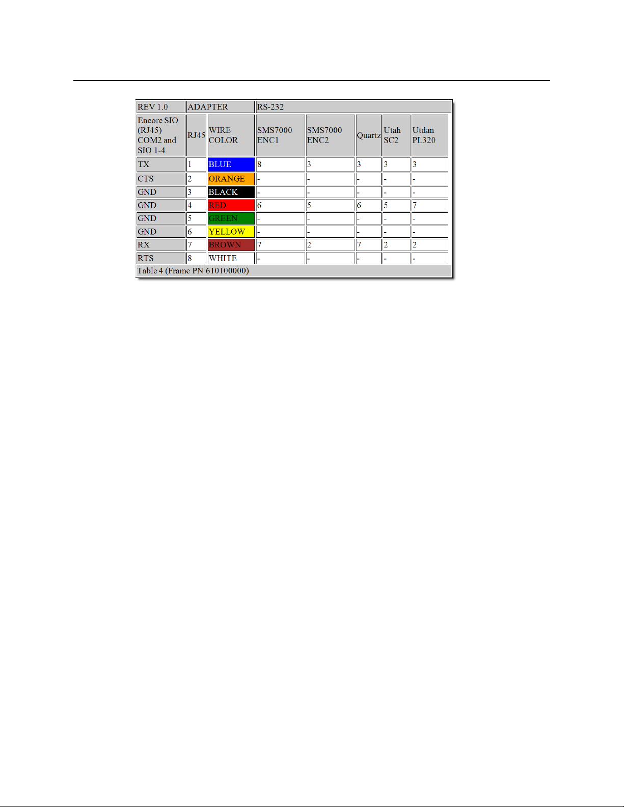
Figure 3-5: Pinouts for frame PN610100000 (RS-232)
Troubleshooting
iControl Router
User Guide
To troubleshoot the serial connection, send the <
router should respond with something like 72 or 75 with some special characters at the
beginning and at the end. The first character has ASCII code 0 × 15 (NAK) and the last one is
0 × 04 (EOT). If you see something like that, then you can assume that the serial port is
configured properly. To troubleshoot the Ethernet connection, try pinging the router first and
if you succeed then try connecting to the router via telnet. To end the telnet session, type
logout.
Lightwave Matrix-Hub 1000
The Matrix-Hub can be connected to the app server by a standard RS-232 cable. The settings
of the serial port are displayed on the router’s screen. The Matrix-Hub router requires that the
user should log on from the serial port. In order to automate this, set the name of the physical
router to the password. The default password is
mode, then the name of the serial level should contain the string 422, for example, you can
name it Serial-422. If that string (
mode.
It is impossible to do both 422 and 232 switches. The system always assumes that the Video
level has frame ID 1, the K/M level has frame ID 2 and the serial level has frame ID 3. Note that
the K/M switch takes about 0.5 seconds, so there is a noticeable delay. The K/M and serial
connections are
although a bug in Matrix-Hub firmware sometimes allows you to do that). It means that if the
source was connected to a destination, and then user connects it to another destination, the
first destination is disconnected automatically. A video source can be connected to several
destinations simultaneously.
unicast (that is, you can connect one source to only one destination
Ctrl+D
mh1. If you want to do all switches in RS-422
422) is not found, then all the switches are done in RS-232
> character to the serial port. The
43
Page 48

Routing Switchers Tips and Tricks
Troubleshooting
Troubleshooting
When you’re connected, hit enter. The system should response either with a password prompt
or with a command prompt (MatrixHub#).
Snell (Pro-Bel)
SW-P-08 (General Remote Control Protocol)
This driver uses the general remote protocol (SW-P-08) to communicate with any Snell (ProBel) controller supporting that protocol (System2, System3, Aurora, Freeway, Nebula, etc.). You
may use RS232 or RS422 to communicate with the controller. Data rates are typically 9600
bauds on an RS232 link and 38400 bauds on the RS422 link. The selection may be applicationspecific and it is usually configurable on the controller itself using the manufacturer’s
software. Data is transmitted asynchronously as 8-bit data bytes, no parity framed by one start
bit and one stop bit to make a 10-bit data frame. Parity may be used if the controller supports
it. Be aware that this protocol uses both matrix and level ID. You can set the matrix ID of a
particular level in the level configuration panel when configuring physical router in Router
Manager. Level and matrix ID are considered zero-based in Router Manager. You must specify
the matrix ID for each level you define. Here is an example: You have one Aurora controller and
two physical routers, each one containing three levels. Depending on how you configured the
aurora controller, you can set it up so the first router is identified as Matrix 1 and the second
one as Matrix 2. In Router Manager, you will add only one physical router that represents the
Aurora controller. Then you will add three levels for Matrix 1 and three others for Matrix 2.
SW-P-02 (General Switcher Communication Protocol)
This driver uses the general switcher communication protocol (SW-P-02) to communicate with
any Snell (Pro-Bel) switcher supporting that protocol (e.g. Halo, Sirius, etc.).
Note: This driver can also be used with a router controller such as a VikinX Modular
router's SysCon card or an external ETH-CON device provided you have purchased
the appropriate license (P-88) from Nevion (Network Electronics) for your controller.
The default communication parameters are:
•
RS485/RS422
• 8 bit DATA
• 1 STOP bit
• EVEN Parity
• 38.4K Baud
The parameters may be application-specific and they are usually configurable on the Snell
(Pro-Bel) switcher itself, by using the associated software. Data is transmitted asynchronously.
44
Page 49

iControl Router
User Guide
This protocol is also supported over IP. The default port is 2000, but it may be configured to
something else. If the switcher does not have an Ethernet port, you can use the Pro-Bel Babel
Fish box:
Troubleshooting
If you want to troubleshoot the SW-P-02 over IP connection, use the following Pro-Bel tools:
•
HU-Babelfish Internal Protocol Conversion V03.pdf
• IPConfigurationTool V4.00.zip
• swp02_test.zip
NVISION
NVISION Ethernet Protocol - Enterprise Router
NVISION Enterprise routers use TCP/IP to communicate with external devices. The port must
be 9193. You also need to specify the NVISION controller's host name or IP address when
configuring it in Router Manager.
To configure the NVISION controller, you must match the iControl Router frame ID with the
unique ID of the router defined in the NVISION configuration. Also, the iControl router logical
levels should match the levels defined in the NV9000 configuration.
Router Protocols that NV9000 Supports
The NV9000 router controller supports any of the following router protocols:
•Utah RCP-1
• Jupiter ESbus
• GVG Horizon TCI
• Snell (Pro-Bel) SW-P-02
• Snell (Pro-Bel) SW-P-08
•Pesa
• ISIS Serial
• Datatek D-2815 Serial
•Sony CART+ Serial
45
Page 50

Routing Switchers Tips and Tricks
Troubleshooting
• Jupiter ESSwitch
• Encore Router
•Sierra Video
•Stagetec Nexus
Troubleshooting
There is a known issue with TCP/IP in iControl Router Standalone version 1.70. If you see a lot
of exceptions in the console of the router service, please contact Miranda Technical Support.
You may have to upgrade your iControl Router Standalone installation. The problem has been
seen when running iControl Router Standalone version 1.70 on a K2.
If you cannot connect to an NV9000 controller, try the following command:
telnet IP_ADDRESS_OF_THE_CONTROLLER 9193
If you get a
connect failed message, it means that the NV9000 is not properly configured for
remote control.
How To...
How to start SE Utilities
1. Connect to NV9000 either directly or via Remote Desktop.
User name: EnvyAdmin
Password: software.
2. On your desktop, double-click on the NV9000-SE Utilities icon.
How to create a physical router in SE Utilities to control a KX router
1. Open SE-Utilities (see page 46).
2. On the Configuration menu, point to Router and click Add Router.
3. Set the router name.
4. Set Router Host to NVCONFIG (default value).
5. Set protocol to NV Ethernet.
6. Set Primary Control Point to the KX IP address (for example, 10.6.6.50).
7. Leave Secondary Control Point blank.
46
8. Click Add to add Physical Level.
9. Set digit under # to match Physical level of KX router in XEdit (normally this would be 0).
10. Set Input Start, Input End, Output Start, Output End to match dimension of KX router.
Input Start must be set to 1, Output start must be set to 1.
11. Click Save.
12. Go to System Management and select NV9000 node in left pane.
13. Click Write Configuration to NV9000 to send config to NV9000.
14. Click Restart Controller 1.
Page 51

iControl Router
User Guide
15. Wait until the NV9000 has finished rebooting.
You should see all accessible routers visible in Left pane.
16. Select KX router in left pane.
You should see cross point status in central pane. You can also test switching KX router
crosspoints by using Take area.
How to switch a crosspoint from SE Utilities
1. Go to System Management and under Routers, click on the router you want to control
2. If you can communicate with that router, in Connections panel, you will see the current
crosspoint for each output
3. To change a crosspoint, select appropriate input and output inside Take section and click
Ta ke.
How to determine the physical level ID and matrix size you need to set up in Router Manager to control a router configured in SE Utilities
1. Start SEUtilities (see page 46).
2. Go to Views | PhysLevels and check value under ID column for matching router.
3. Check Input End and Output End fields to determine matrix size.
Note: Make sure Input Start and Output Start are set to 1
How to determine the virtual level ID and matrix size you need to set up in Router Manager to control a router configured in SE Utilities
1. Start SEUtilities (see page 46).
2. Go to Level Sets -> Virtual Levels and Check ID column.
How to find the NV9000 controller version
1. Log on to NV9000 using RemoteDesktop.
Default username:
EnvyAdmin
Default password: software
2. Using Windows Explorer, navigate to c:/nvision/envy/bin.
3. Right-click the Explorer dialog column header and make the Product Version column
visible.
How to set up virtual router from SE Utilities (or to change protocol used by NV9000 to control external router)
Note: This is useful, when not having actual router connected.
1. Start SEUtilities, and go to Views | Router control (see page 46).
2. Set router protocol to Virtual router (or to different protocol).
3. Export config on NV9000.
47
Page 52

Routing Switchers Tips and Tricks
How to export NV9000 backup database
How to export NV9000 backup database
1. Start SEUtilities (see page 46).
2. On the File menu, click Export to Zip Archive.
3. Browse, select and click Save.
How to create a backup of NV9000 database
1. Start SEUtilities (see page 46).
2. Go to System Management and select Read configuration from.
You will be asked to open a configuration to receive data.
3. Select New and enter a name for the backup, and then click OK.
The name of your backup should appear in the SEUtilities menu bar.
How to import an NV9000 backup database
1. Start SEUtilities (see page 46).
2. On the File menu, click Import From Zip Archive.
3. Browse, select, and then click Open.
4. Select a name for the imported config and click OK.
5. Go to System Management and click Write configuration to… to load configuration on
controller.
6. Click Restart controller 1 (or Stop controller 1 followed by Start controller 1).
How to export a configuration from SE Utilities to NV9000
1. Start SEUtilities (see page 46).
2. On the System Management menu, click Local Control System.
3. Click Write configuration to LOCAL CONTROL SYSTEM.
How to change source labels from SE Utilities
The purpose is to modify the source labels from the SEUtilities application so Router Manager
is dynamically updated with this information.
1. Start SEUtilities (see page 46).
2. On the Configuration menu, click Devices.
3. Click on the device name you want to change and then click Edit Selected Devices.
4. Edit the name as desired, and then click Save.
5. Go to System Management and click on root node (in tree).
6. Click Dynamic Update Apply changes to.
48
Note: The NV9000 does not accept timeout values smaller than 500 ms.
Page 53

iControl Router
User Guide
How to increase a timeout for NVEthernetProtocol
When the NV9000 is using nvethernet (np0016 over TCP/IP) to control a router, it is polling the
router every 300 ms and it expects a response from the router within 500 ms. If the NV9000
doesn’t receive the response within 500 ms, SEUtilities will show the router as being offline.
To set the timeout value to a larger custom value
1. In SEUtilities, select Views | Tab le s | Control Points (see page 46).
2. By default, you should see a Parameter entry similar to:
E,10.0.9.39,T500, where 500
represents the timeout in milliseconds and 10.0.9.39 is the IP address of the router to
control.
3. Edit the value and click Save.
4. Go to System management, select the root node, and then click Write configuration to.
5. Click Restart controller to apply your changes.
Note: The NV9000 does not accept timeout values smaller than 500 ms.
How to downgrade a database on a controller
Downgrading NV9000 sometimes involves downgrading the database schema.
How to determine controller version
To determine the NV9000 controller version, click on the System management tab, then
mouse over your controller icon to reveal a tooltip. Version software will be the last item of the
list.
Where to find SE Utilities log file
The system log file is under system management.
How to set up NVISION router
In order to configure a NVISION router, big router with a controller card, you have to run
uniconfig software.
How to set up tie lines
You can configure a tieline with Se-Utilities under configuration tab and tielines. Add
upstream and downstream routers and bind them together by connecting output port to
input port with your mouse.
If you want to free a tieline, click on system management tab, and under tieline status, you
could right click on a tieline and free it.
How to turn on Tieline Manager
Turning on the tieline manager is simply a matter of installing the tieline license and restarting
all the software.
49
Page 54

Routing Switchers Tips and Tricks
How to display debug window when launching SE Utilities
How to display debug window when launching SE Utilities
If you hold down the
window. That console window will show debugging output from the application, and it will
most likely tell us exactly what is failing.
How to install SE Utilities on PC
Double-click the
How to upgrade NV9000 / NV915 software
Copy the NVSETUP directory on NV9000/NV915 and then double-click
CTRL
key when you launch SE-Utilities it will also launch a console
SEUtilitiesVx.x.xInstaller.exe file.
NVISION Ethernet Protocol - Enterprise Router (Logical)
NVISION Enterprise routers use TCP/IP to communicate with external devices. The port must
be 9193. You also need to specify the NVISION controller's host name or IP address when
configuring it in Router Manager. After you have created the router and levels with the
appropriate dimension and saved configuration, physical levels will be updated automatically
for you.
Also, in order to fetch labels, take crosspoints or connect free source, NVISION Enterprise
routers will use virtual device id for levels, destinations or sources.
NV9000Setup.exe.
SE Utilities Configuration Hints
To determine the physical Level or frame ID value to set in Router Manager Configurator, from
NV9000 SEUtilities, go to View | Virtual Levels and select the appropriate ID. In order word,
level or frame id = column id in table Virtual levels in SE-utilities
The size is variable, and it can change each time you read mnemonics from the system. You
would need to query the database to obtain the number of sources or destinations in advance
of reading them all using 0x3022.
In order to set the right level size, save your config, open putty to your app server, enable
debug for
log4j and restart the iControl Router service. Then open log file router.log and use the grep
command for string source size and destination size.
com.miranda.icontrol.routers.nv9000virtual.NV9000Virtual to debug in
Note: To determine the physical Level matching this virtual level, from NV9000
SEUtilities, go to Views -> Level Set Details.
Troubleshooting
If you cannot connect to an NV9000 controller, try the following command:
telnet IP_ADDRESS_OF_THE_CONTROLLER 9193
If you get a connect failed message, it means that the NV9000 is not properly configured for
remote control.
50
Configuring NV9000 Routers with Tielines
Steps to perform in SE-Utilities
1. Open SEUtilities (see page 46).
Page 55

iControl Router
User Guide
2. On the File menu, click New, and then type your configuration name (for example
ROUTERS_TIELINES)
3. Add new routers by clicking Routers on the left panel, and then clicking Add router on the
right panel.
4. Type your router name for example ROUTER1 and select the proper protocol (for example
NV compact router ethernet for compact router).
5. Click Add to add a physical level.
6. Do the following sub-steps for all routers:
a) Set values for input start, input end, output start, output end (for example 1, 32, 1, 32)
b) On the Level sets menu, click add levelset, and then type a level name (for example
ROUTER1).
c) Select a virtual level (for example VIDEO) and select the physical level.
Note: It is important to have the same virtual level for all routers, since those
routers will be bind together with tielines.
7. Do the following sub-steps for all routers:
a) On the Devices menu, click Add device.
b) Set a mnemonic name and choose the proper level set (for example DEV 1 and level set
ROUTER1).
c) Set the proper input/output port (for example 1, 1).
Note: To go more quickly, you may also choose to add devices in Ta sk s | Add
multiple devices.
d) Select the proper prefix (DEV), set the proper number of devices (32) and select the
proper level set (ROUTER1).
e) On the Finish menu, click Finish.
8. If you do not have free output and input ports, navigate to Configuration | Device, and
then delete a device that will be used as a tieline (for example DEV 31, 32 and OUT 1, 2).
9. On the Configuration menu, click Tielines.
10. Add tieline, set tieline name (for example tieline1).
11. Select upstream router (for example ROUTER1_PL1).
12. Select downstream router (for example ROUTER2_PL1).
13. Drag your mouse from an upstream port to a downstream port.
14. On the upstream panel (left side) and downstream panel (right side) make sure you check
the checkbox where you see VIDEO level.
15. Click Save.
Steps to perform in Router Manager Configurator
1. Open Router Manager Configurator.
51
Page 56

Routing Switchers Tips and Tricks
How to edit aliases (Name Sets)
2. Add a physical router.
3. Select NV9000 virtual with the IP address of your controller.
4. Click Save.
How to edit aliases (Name Sets)
1. Open SEUtilities (see page 46).
2. Go to System Management.
3. Click NV9000 (root node).
4. Click RMB and select Edit name sets.
NVISION Ethernet Protocol - Compact Router
NVISION Compact routers uses UDP to communicate. The port must be 5194. You also need to
specify the NVISION router's host name or IP address when configuring it in Router Manager.
How To...
How to modify the IP address on a compact router
1. Start the
2. Go to the CR Series Network Setup | CR Series Ethernet Settings panel.
3. Edit the IP address and click Apply Updates.
CrConfigurator.jar application.
Note: Automatically discovered CR panels will appear in CR Series Ethernet
Settings section.
Pesa
The Pesa router is equipped both with RS-232 and RS-422 ports. In order to connect to the RS232 port you will need a straight cable. When using the RS-422 port, you may use an Addenda
Electronics Rosetta Stone converter (http://www.addenda-elect.com/) or similar to
connect the router to the PC. Note that the use of RS-422 has not been tested, so the use of RS232 is recommended.
Miranda's Router Control Software supports two protocols for Pesa devices:
• CPU Link Protocol No. 1 or P1 (referred to as simply Pesa in Router Manager)
• Unsolicited Status Protocol or USP (referred to as Pesa USP in Router Manager)
CPU Link Protocol No.1 or P1 (Pesa)
52
The default settings for the ports are:
•
9,600 baud
• 8 data bits
• No parity
Page 57
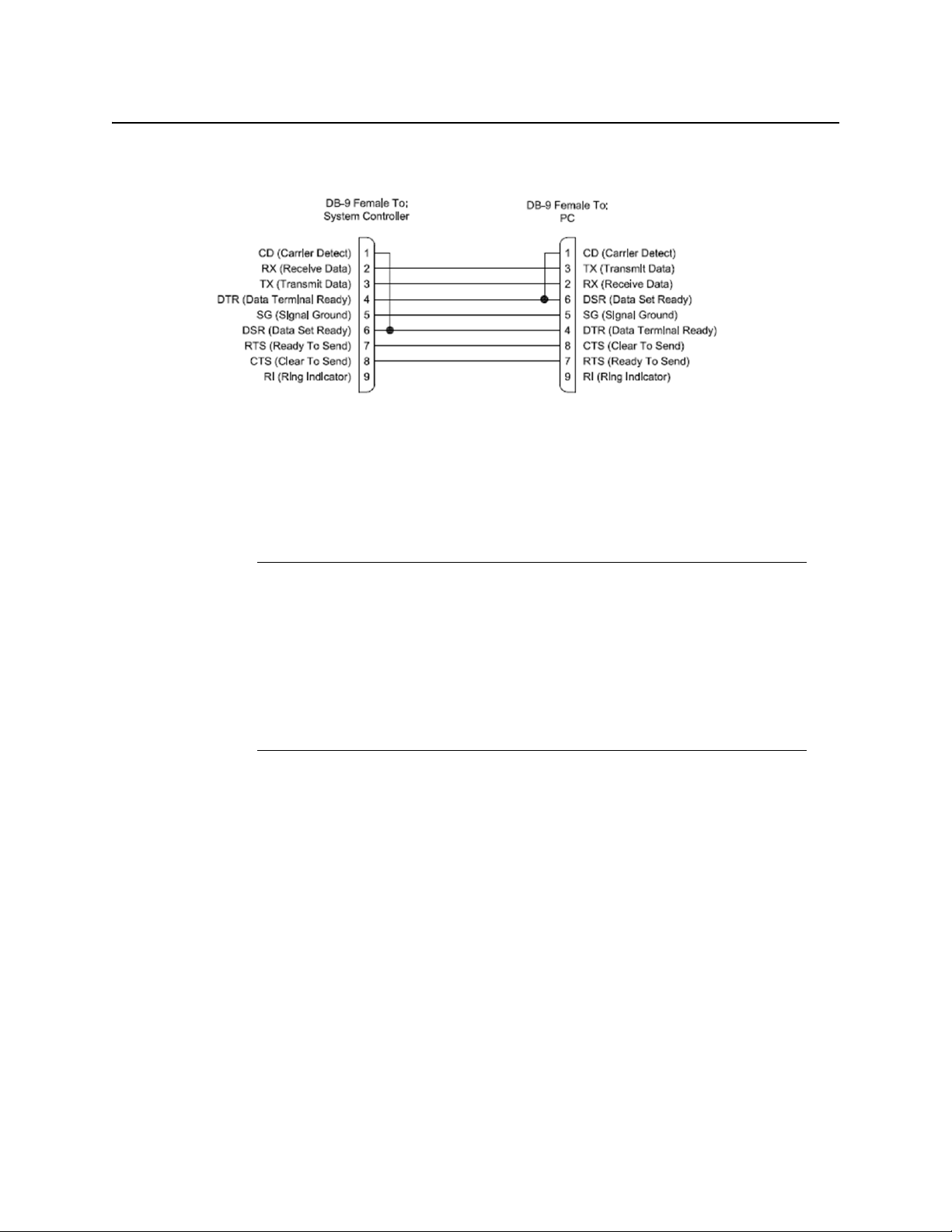
iControl Router
User Guide
• 2 stop bit
Figure 3-6: RS-232 serial cable
Depending which Pesa router controller you have, it may be possible to change the bit rate to
38,400 baud. The Pesa driver has been tested at that speed but it seems to generate a lot of
errors during transmission, so it is not recommended to use 38,400 baud. Please be sure to use
9,600 baud rate when configuring the Pesa controller. This driver uses the PESA checksum, as
opposed to HEXA or NONE.
Notes
• This driver does not support unsolicited crosspoint changes. This means that
a crosspoint changed via a control panel will not be reported to the other
panels until the next polling. The polling is currently set to 5 sec.
• Crosspoint changes made using matrix or single bus are applied rapidly but
the matrix button reporting the status will not be selected until the next
polling. Thus a crosspoint status will take between 0 and 5 sec to display on
the matrix.
When configuring a Pesa router in iControl Router, make sure you configure ALL levels starting
with level #1. If your router is using level 1, 2 and 3 and you only want to control level 3, you
must also configure physical levels 1 and 2 in iControl Router.
Unsolicited Status Protocol (Pesa USP)
The primary medium for the USP is an asynchronous full-duplex connection that is usually run
over RS-232 or RS-422 (this is dependent upon the control system). Data is transmitted over
the bus asynchronously. The data is sent at user selectable baud rate (default to 38.4 K Baud)
with 1 start bit, 8 data bits, no parity, and 1 stop bit. The default method of handshaking is
RTS-CTS control though some controllers may allow for methods such as XON-XOFF.
If you want to use a high communication speed (for example, 38,400 baud), you should use
this driver. However, be really careful because this protocol is label-based and you must
correctly define all the physical source and destination labels in Router Manager in order to
make this driver work properly. This driver does not use checksum.
53
Page 58

Routing Switchers Tips and Tricks
Troubleshooting
With firmware version 3.3 and earlier, SD commands must be sent with a comma before the
terminator.
Notes
• The Pesa USP driver supports Matrix Controller firmware version 3.3 and
earlier.
• Every physical router destination label defined in XEdit must match a
destination label specified in the Pesa router’s configuration.
• This driver does not support checksums. To turn off the checksum, open
PERC2000 (version 2.1), click System Parameters, and then set the checksum
options to NONE for every port.
• If your Pesa router has an older controller card that was upgraded to the
PERC2000 software, the USP filtering could be enabled even if the
configuration file indicates that it is not. If you notice that UMD statuses do
not reflect crosspoint changes immediately, try enabling all filtering on the
router, and then disabling all filtering. In some cases enabling filtering of all
unsolicited status from the router will be necessary.
• Miranda’s Router Control Software cannot communicate with the router
when RTS-CTS flow control is enabled.
• In the 3500+ series controller for the Pesa router, RTS-CTS is enabled at the
hardware level and cannot be disabled. In the case of PERC2000 controllers,
flow control is optional and configured in the PERC2000 Software.
• Level or Frame ID designation in Router Manager or XEdit must be set to
when controlling a single Pesa router. Increment by 1 if there are multiple
routers to be configured.
• You must use RS-232 communication to communicate to the router.
• In some instances, after a reboot of the router or the KX/iControl, the
mnemonics will not update on the KX/iControl display automatically. Making
a crosspoint change to the router will cause an update to occur.
1
Troubleshooting
In the case where the driver is not working, you can always troubleshoot with HyperTerminal.
Using TeraTerm or HyperTerm, you can send commands to the serial port and see the
responses coming back. Connect to the system controller's serial port using terminal program
Ctrl + j
of choice. Press
indicating that the command was in error since there was no actual command.
Using the
checksumcalc.exe program, enter a command in the command box. Press Calc
Checksum, and press Copy to Clipboard. Switch to terminal program and paste the
command, and press
a CR LF pair when enter is pressed. If this is not the case, then you can press
Ctrl + j
to send the CR LF pair.
to send an LF character and the controller should respond with an E
<Enter>
. This will only work if you have the terminal program set to send
Ctrl + m
and then
54
Page 59

Sony
Quintech
Quick Info
iControl Router
User Guide
The Sony protocol is not directly supported. However, a specific Sony card can be used to
emulate the GVG Series 7000 Native Protocol. The card is named HKSPC and it only supports
Ethernet connection. Please use the Sony HKSPC (GVGNP Emulator) driver with the HKSPC card
and not our GVG 7000 Native Protocol driver.
Ethernet vs. Serial Communications
The initial task in setting up the communications parameters involves specifying whether
Ethernet or serial communications will be used. If you choose Ethernet, you will be prompted
to set the Ethernet address and port. The default port is 9100. It should not need changed
unless port 9100 is not allowed on your network. If a new port will be specified, make sure that
it matches the port setting of the matrix controller. The default port value of the matrix
controller is also 9100.
Serial Communication Settings
Use the Control In port on the controller (UCM). The serial port parameters are the same
regardless of whether RS-232, RS-422, or RS-485 is being used. The parameters are fixed at
9600 baud, 8 data bits, no parity, and 1stop bit (8N1).
Figure 3-7: Pinout for Quintech serial port
55
Page 60

Routing Switchers Tips and Tricks
Detailed Info
Detailed Info
System Access
A Quintech matrix switching system is controlled by a standard Universal Control Module
(UCM). This is typically a separate 1 RU (1.75") module, but it may be built into a matrix
module. The UCM accepts control commands from external sources that tell it how to switch
the matrix or configure various system options. A standard UCM has five control ports that will
accept commands:
Local: Front panel keypad and LCD.
Remote: The Remote In connector. This is typically where other UCMs are connected when
they are configured to operate as remote control panels. If remotes are not going to be used in
the system, this port can typically be used as an auxiliary serial port. It is configured as an RS485 port and accepts 9600-baud 8N1 (8 data bits, no parity, 1 stop bit) data. Command data is
sent as an STX/ETX bounded packet with checksum as defined in the protocol document.
Note that the Remote In connector is directly connected to the Remote Out connector since
this is an RS-485 bus connector.
Control In: The PC Control In connector. This is typically where a control computer or PC is
connected. The port can be configured as an RS-232, RS-422, or RS-485 port and accepts 9600baud 8N1 data. Command data is sent as an STX/ETX bounded packet with checksum as
defined in the protocol document.
QEC Port: Ethernet. The exact Ethernet port is user-defined with the default Ethernet port set
9100. It accepts the same command packet that is used on the serial port. This makes it easy
at
for a single driver to be used for both serial and Ethernet connections.
Te ln e t: Telnet console window. This provides an ASCII interface with a cursor for keyboard
entry of commands.
The system is highly flexible. The access control feature can be configured to be on/off for
each of the five possible control ports on an individual UCM. This also holds true for a system
with a main UCM and multiple remote UCMs. The control port access control must be set
separately for the main unit and each of the remotes.
UCM Control In Connection
The Control In port of the UCM is where serial port data from a PC is accepted. The Control In
port can either be left unused or it can be used for serial communications control of the
matrix. Serial control can be established using any UCM, including remotes.
All operations of the matrix can be controlled from the UCM Control In port which is typically
connected to a PC. The connector is configurable and can communicate in one of three serial
interface standards: RS-232, RS-422, and RS-485. Software configuration is covered later in the
Serial Interface Menu section of this manual.
UCM Control In Connector
The UCM has a standard DB-9 female serial connector labeled Control In on the back panel.
The pin definitions depend upon how the serial port is being used. The connector's pinouts
are shown in see Figure 3-7, on page 55.
56
Page 61

iControl Router
User Guide
UCM Control In Cable
The UCM Control In port is shared for both RS-232 and RS-422/485 interfaces. A NULL MODEM
or crossover cable is not required on this port and, in fact, the system will not work using a null
modem adapter or null modem cable. Use only a straight through one-to-one cable.
UCM Control In Serial Communication Settings
The serial port parameters are the same regardless of whether RS-232, RS-422, or RS-485 is
being used. The parameters are fixed at 9600 baud, 8 data bits, no parity, and 1 stop bit (8N1).
UCM Control In RS-232 Description
RS-232 was designed for communication of local devices It supports one transmitter and one
receiver. This standard uses single ended signals over unbalanced, unterminated wires. Single
ended means the signal is sent over one wire with respect to a single ground source.
Unterminated means the signal lines do not have impedance matching at the line ends. This
interface is useful for point-to-point communication at slow speeds and over short lengths of
cable. Most PCs come equipped with one or more RS-232 serial ports.
RS-232 Advantages / Disadvantages
RS-232 is easy to implement and has been standardized and accepted for years. Due to the
nature of RS-232, the signals are susceptible to noise and grounding problems. These
problems set a limit to cable lengths. Quintech recommends that when using RS-232, the
cable length be limited to 20 meters or approximately 60 feet. RS-232 employs point-topoint
communications, so only two devices will typically communicate with each other over the
RS-232 standard.
UCM Control In RS-422 Description
In RS-422 communications, a pair of twisted wires is used to carry a signal. The data is encoded
and decoded as a differential voltage between the two lines. As a differential voltage, the
interface is, in principle, unaffected by differences in ground voltage between sender and
receiver.
RS-422 Advantages / Disadvantages
RS-422 differential signals over twisted pair wires are less affected by noise. They therefore can
communicate at faster rates and over longer distances. RS-422 connectors are not
standardized like RS-232. Although better than the RS-232, RS-422 is still limited to one master
and up to ten receivers on the bus. Recommended maximum length is 4000 feet. The
Quintech RS-422 standard is limited to 10 receivers.
UCM Control In RS-485 Description
The UCM can be configured to communicate in RS-485 standard.
57
Page 62

Routing Switchers Tips and Tricks
UCM Control In Cable
58
Page 63

Overview
The Router Manager Configurator interface has two panes. The left pane always displays a
hierarchical list of folders which can be expanded to expose more detailed information.
The Router Manager folder is always at the top level in the list, and typically includes the
Physical routers and the Logical routers subfolders. The subfolder structure is variable and is
established during the system setup. There are two tabs at the top of the left pane:
Configuration and Dynamic Control.
In either tab, click a folder or a list item to select it; double-click a folder to open it. Both tabs
also have a tool bar with buttons to open and close the router manager folder, at the top of the
list (not the currently selected folder). The Close button is available when the router manager
folder is open; conversely, the Open button is available when the router manager folder is
closed. The Configuration tab also has a Save button which becomes available whenever you
make some change to the system configuration.
Configuration Interface
•Use the Configuration tab to set up and configure your system, after which the router
service and clients must be restarted for changes to become effective.
•Use the Dynamic Control tab to perform any of a subset of live configuration changes,
after which no restart is required.
The right pane displays data-entry zones and information areas associated with the current
left-pane selection. When a logical router is selected in the left pane, the right pane has
additional tabs.
System Recommendations
Miranda recommends the following hardware specifications for optimal performance:
Recommended hardware specifications for optimal performance
Memory Processor Operating System
2 GB RAM Intel Core i3 or better Windows 7 or Windows XP Professional
Miranda requires that the following software is installed on your client PC:
Minimum software requirement
Java 2 Runtime Environment (JRE) version 1.5 or later.
Page 64

Configuration Interface
Detailed Directions
Detailed Directions
The procedures outlined in the following sample workflow are tasks performed exclusively on
the Configuration tab:
Sample workflow: Configuring routers
Open Router Manager Configurator (see page 60).
1.
Define all of your physical routers. Do one of the following, as required:
2.
• "Adding Physical Routers" on page 64
• "Importing an NVISION Physical Router Configuration" on page 67
[OPTIONAL] Assign aliases to physical input and destination port (see "Adding Aliases for
3.
your Physical Input Ports", on page 75).
[OPTIONAL] Remove any physical routers that you would like to remove (see page 81).
4.
[OPTIONAL] Modify any pre-existing physical router configurations, if required
5.
(see page 78).
Define levels for your physical router definitions (see "Adding Physical Router Levels",
6.
on page 72).
[OPTIONAL] Modify or remove any pre-existing physical router level definitions, if required
7.
(see "Modifying Physical Router Configurations", on page 78).
Define all of your logical routers (see "Configuring Logical Routers", on page 82).
8.
[OPTIONAL] Remove any logical routers that you would like to remove (see "Configuring
9.
Logical Routers", on page 82).
Define levels for your logical routers (see "Configuring Logical Routers", on page 82).
10.
[OPTIONAL] Modify any pre-existing logical routers and their levels, if required
11.
(see "Configuring Logical Routers", on page 82).
[OPTIONAL] Remove any logical router levels, if required (see "Configuring Logical
12.
Routers", on page 82).
Configuring Routers
Starting Router Manager Configurator
REQUIREMENT
Before beginning this procedure, make sure you have started iControl.
To start Router Manager Configurator
60
1. On the
iControl—Startup page, click the massive i icon.
Page 65

The iControl Launch Pad executable file is downloaded to your local file system.
2. Double-click the executable file.
iControl Router
User Guide
3. On iControl Launch Pad, either type in the IP address of your Application Server or select
from the list of available IP addresses.
4. Click the iC Router Control icon.
The iC Router Control Connection window appears.
61
Page 66

Configuration Interface
Starting Router Manager Configurator
5. Perform the following tasks in the iC Router Control Connection window, as required:
To do this.. . ...do this...
Connect to a different Router
Manager’s IPaddress (other than
the one currently displayed)
1. Click within the Connected to box.
2. Delete the existing IP address.
3. Type the new Router Manager’s IP address.
4. Click Connect.
62
Open Router Manager
Confi gurator
Start router control software.
6. In
Router Manager Configurator, select a router component on the left to view related
•Click Router Manager.
1. Select the desired item under Matrix view.
2. Click Open.
information and options on the right.
For example, click Physical Routersto view a list of routers currently defined in iControl.
Page 67

iControl Router
User Guide
Click the folder corresponding to a specific router to view its configuration details.
Click on a level to view its configuration details.
63
Page 68

Configuration Interface
Adding Physical Routers
Adding Physical Routers
Note: Although it is possible to perform the following procedure as a stand-alone
task (assuming all stated requirements are met), Miranda recommends you
familiarize yourself with the sample workflow on page 60 in which this procedure is
only one step within a sequence.
REQUIREMENT
Before beginning this procedure, make sure you have opened Router Manager
Configurator (see page 60).
To add a physical router
1. In Router Manager Configurator, on the Configuration tab, select the router manager
folder (named RouterManager in the graphic, below), and then click Open.
2. Select the Physical Routers folder.
64
Page 69

A list of all physical routers added so far to your system appears in the right pane.
3. Click Add Router.
iControl Router
User Guide
A new Router N folder appears in the Physical Routers folder on the left, and detailed
data-entry areas appear in the right pane.
4. In the Router name box, type a name for the router.
65
Page 70

Configuration Interface
Adding Physical Routers
IMPORTANT: Naming Restrictions
5. In the Router protocol list, select a protocol.
6. Click Help to review information about the selected protocol.
Do not use special characters in the router name. Spaces are allowed.
Note: Presently, there are several protocols for which online help is unavailable.
7. Under Connection type, select Serial, TCP/IP, or UDP, as appropriate for the selected
protocol.
The Communication parameters zone varies according to the selected connection type,
as follows:
66
Figure 4-1: Communications settings for a serial connection
Page 71

iControl Router
User Guide
Figure 4-2: Communications settings for a TCP/IP connection
Figure 4-3: Communications settings for a UDP/IP connection
8. In the Communications parameters area, specify all required information, or click Use
protocol defaults to apply the selected protocol’s default communication settings.
9. Click Save at the top of the left pane.
Notes
• The collection of protocol-specific information, that you can read by clicking
Help for each protocol, can also be found at the end of this manual
(see "Routing Switchers Tips and Tricks", on page 33).
• The RS-232 baud rates for Network routers differ from model to model.
Although the standard value is 19200, you should refer to your router’s user
manual to verify the appropriate value for your specific model.
Importing an NVISION Physical Router Configuration
IMPORTANT: Risk of Deleting Router Configuration Data
If, after adding aliases, you are importing router configuration data in which
there is a physical router with the same name as one of your own in iControl
Router, the alias data you configured for that router will be overwritten.
67
Page 72

Configuration Interface
Importing an NVISION Physical Router Configuration
REQUIREMENTS
Make sure you meet the following conditions before beginning this procedure:
• You have available the host name or IP address of the NVISION router controller whose
configuration you would like to import.
• You have opened Router Manager Configurator (see page 60).
To import an NVISION configuration
1. Select the RouterManager folder, and then click Open.
2. Select the Physical routers folder.
The list of all physical routers added so far to your system appears in the right pane.
3. Click Import NVISION config.
The Import Configuration window appears.
68
Page 73

iControl Router
User Guide
4. In the Host name / IP address box, type the host name or IP address of the NVISION router
controller whose configuration you would like to import.
5. Click Fetch preview.
The levels of the NVISION router appear listed in the Import preview area.
6. Select the levels you would like to import, and then click OK.
69
Page 74

Configuration Interface
Importing an NVISION Physical Router Configuration
A confirmation window appears.
IMPORTANT: Risk of losing current router configuration data
If you click OK in the confirmation window and then click Save in Router
Manager Configurator, the imported NVISION data will permanently
overwrite any existing configuration data.
A progress window appears, allowing you to cancel the operation if required.
7. After the confirmation window disappears, click Save to overwrite your configuration data
with the newly imported data.
8. Refresh your browser.
The NVISION router controller’s level configurations are listed among the physical routers in
the left and right panes of the Router Manager Configurator.
70
Page 75

iControl Router
User Guide
Selecting the physical router in the left pane yields general information, communication
parameters, and a list of levels imported from the router.
71
Page 76

Configuration Interface
Adding Physical Router Levels
Adding Physical Router Levels
The physical levels from which the router is going to be built must be defined. Typical levels
include video, audio 1, audio 2, etc. These levels each represent a physical device. Each level
must be named, and its type and size specified.
IMPORTANT: Using Telecom and Data Routers
Note: Although it is possible to perform the following procedure as a stand-alone
task (assuming all stated requirements are met), Miranda recommends you
familiarize yourself with the sample workflow on page 60 in which this procedure is
only one step within a sequence.
• Network series RS-422 Data routers have to be configured as an audio level.
Select an appropriate audio frame type. For example, if you have an 8 × 8 RS422 router, you should select Network Audio 8 × 8 frame type.
• Network series Telecom routers are configured to work as a video level so you
can use an appropriate video frame. For example, if you have an 8 × 8
Telecom frame then you should select Network Video 8 × 8 frame type.
REQUIREMENT
Before beginning this procedure, make sure you have opened Router Manager
Configurator (see page 60).
To add a level to a physical router
1. In Router Manager Configurator, in the left pane, select the physical router you wish to
configure.
The list of existing levels appears under Levels.
72
Page 77

iControl Router
User Guide
2. Click Add level.
The Physical Level Configuration window appears. Its content varies according to the
selected router protocol:
Figure 4-4: Physical Level Configuration window (for most protocols)
73
Page 78

Configuration Interface
Adding Physical Router Levels
Figure 4-5: Physical Level Configuration window (for a Snell SW-P-08 device)
Figure 4-6: Physical Level Configuration window (for a Redundancy Control device)
3. In the Level name box, type a name for this level.
4. Click Edit.
The Edit Level Size window appears.
5. Specify the number of sources and destinations associated with the physical level.
Note: The three option buttons labeled Video, Audio and Other are used for
Network Electronics routers only, for which levels must be classified as either Video or
Audio. These settings are ignored by routers from other manufacturers.
6. In the case of a Snell SW-P-08 device, type the appropriate value in the Matrix ID box (click
Help for more information).
74
Page 79

iControl Router
User Guide
7. In the case of a Redundancy Control device, select the appropriate main level and backup
level from the lists (click Help for more information).
8. Click OK to close the Edit Level Size window.
9. Click OK to close the Physical Level Configuration window.
At this point, you have added a level to a physical router, which appears in the Levels list
under the Configurations tab.
Figure 4-7: Newly added physical router level
Notes
• If you have several 16 × 2 frames configured to work together then you have
to add only one frame and select an appropriate frame type on the Edit
Physical Level window. For example, if you have three 16 × 2 video frames
configured to make a 48 × 2 router then you should select a Network Video
48 × 2 frame type.
• When the tab is opened, data boxes will appear in which the name, Frame
Type, Frame ID and Physical Level ID can be entered, and two charts (tabaccessed) will appear below in which the Sources and Destinations can be
identified and labeled.. These should conform to the actual physical
connections made to the router being controlled.
The Frame ID in the physical level configuration is the frame address that is set by the
DIP switches on the router frame. The Physical Level ID is the internal identifier of the frame
and should be unique within each physical router. If it's not unique, then you will get an
error message when you try to save the changes. The Matrix ID is an optional entry for a
Probel router.
The Physical Router definition is now complete.
Adding Aliases for your Physical Input Ports
Aliases are names assigned to input and destination ports. Aliases are useful when trying to
remember specific ports on different routers or devices, or on different physical levels, that
have identical port numbers. For example, input port 1 on Router 1 can be assigned the alias
router1on1 and input port 1 on Router 2 can be assigned the alias router2on1 so that each port
can be easily distinquished.
75
Page 80

Configuration Interface
Adding Aliases for your Physical Input Ports
IMPORTANT: Risk of Deleting Router Configuration Data
If, after adding aliases in iControl Router, you decide you would like to import
router configuration data in which there is a physical router with the same name
as one of your own in iControl Router, the alias data for that router will be overwritten.
Notes
• If you would like to add aliases, you may either create your own or import
them from an NVISION router configuration.
• In iControl Router Web, you may create alarm consumer plug-ins that are
triggered by the alarms of aliases.
REQUIREMENTS
Make sure you meet the following conditions before beginning this procedure:
• You have opened Router Manager Configurator (see page 60).
• The physical router and level to which you would like to add an alias is visible in the
navigation pane of the Router Manager Configurator.
To add an alias for an input or destination port
1. In Router Manager Configurator, in the navigation pane, click the level of the physical
router to which you would like to add an alias.
76
Information about the selected level appears in the right pane, including labels and aliases
for sources and destinations.
Page 81

iControl Router
User Guide
2. If you would like to add an alias for an input port, click the Sources tab. If you would like to
add an alias for a destination port, click the Destinations tab.
3. Click Add aliases.
77
Page 82
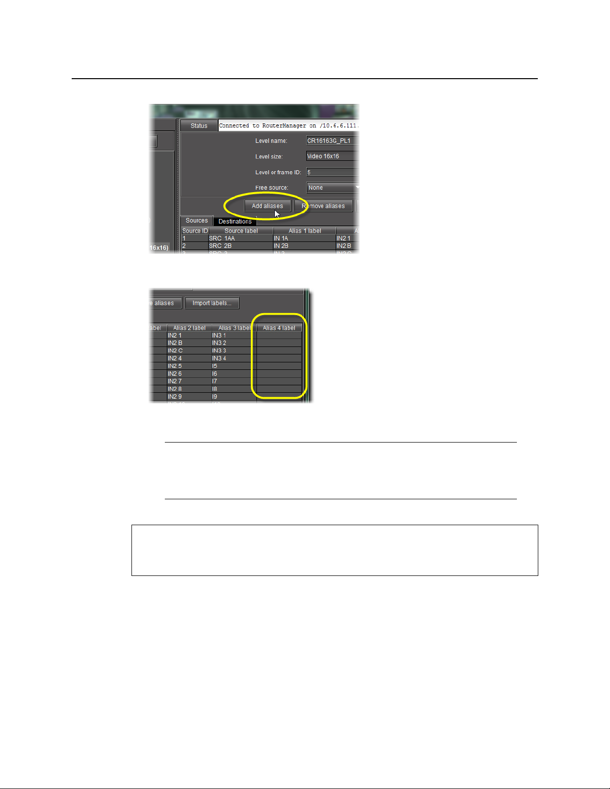
Configuration Interface
Modifying Physical Router Configurations
An empty alias column appears to the far-right side of the label area.
Modifying Physical Router Configurations
Note: Although it is possible to perform the following procedure as a stand-alone
task (assuming all stated requirements are met), Miranda recommends you
familiarize yourself with the sample workflow on page 60 in which this procedure is
only one step within a sequence.
REQUIREMENT
Before beginning this procedure, make sure you have opened Router Manager
Configurator (see page 60).
To modify a physical router’s configuration
1. In Router Manager Configurator, in the router manager folder, double-click the Physical
Routers sub-folder.
78
Page 83

Figure 4-8: Router Manager Configurator (Physical routers folder indicated)
A series of folders appears, one for each physical router.
iControl Router
User Guide
Figure 4-9: Expanded Physical routers folder (physical routers circled)
2. If you would like to modify router settings (as opposed to router level settings), perform the
following sub-steps:
a) Select the appropriate physical router in the left pane.
The right pane is populated with the current settings for the selected physical router.
79
Page 84

Configuration Interface
Modifying Physical Router Configurations
Figure 4-10: Right pane of Router Manager Configurator (physical router settings)
b) Modify the physical router settings as required.
3. If you would like to modify the settings of a particular level belonging to a physical router,
perform the following sub-steps:
a) In the left pane, double-click the appropriate physical router.
The levels within the router become visible.
Figure 4-11: Expanded router folder (levels circled)
b) Select the level whose settings you would like to modify.
The right pane is populated with the current settings for the selected level.
80
Page 85

iControl Router
User Guide
Figure 4-12: Right pane of Router Manager Configurator (physical router level settings)
c) Modify the level settings as required.
4. Click Save.
Removing Physical Routers
Note: Although it is possible to perform the following procedure as a stand-alone
task (assuming all stated requirements are met), Miranda recommends you
familiarize yourself with the sample workflow on page 60 in which this procedure is
only one step within a sequence.
REQUIREMENT
Before beginning this procedure, make sure you have opened Router Manager
Configurator (see page 60).
To remove a physical router
1. In the RouterManager folder, select the Physical routers sub-folder.
81
Page 86

Configuration Interface
Configuring Logical Routers
The list of physical routers appears in the right pane.
2. Select the router you wish to remove from the list, and then click Remove Router.
3. Click Save.
Configuring Logical Routers
A Logical Router is a virtual router whose functionality is determined by the software. Logical
routers have a name, sources and destinations. See the following table for common tasks
associated with logical routers.
Note: Although it is possible to perform any of the following as stand-alone tasks,
Miranda recommends you familiarize yourself with the sample workflow on page 60
in which these tasks comprise only one step within a sequence.
IMPORTANT: Once you have configured the logical router, it is important not to change its
name. Doing so will disable any settings that refer to the existing router name,
including:
• logical source assignments for source or destination label
• external router connection configurations
• monitors and background actions associated with the logical router
• automatic crosspoint changes on video monitors (router source property)
Note: If you change the name back to the original, everything should work as
before.
82
Page 87

REQUIREMENT
Before beginning this procedure, make sure you have opened Router Manager
Configurator (see page 60).
To do this... ...do this...
iControl Router
User Guide
Display all currently defined
logical routers
Display general information
about a logical router
Define a new logical router
Select the Logical routers folder in the left pane.
1. Expand the Logical routers folder in the left pane.
2. Select the appropriate logical router.
1. Select the Logical routers folder in the left pane.
2. Click Add router in the right pane.
1
83
Page 88

Configuration Interface
Configuring Logical Routers
(
Continued
To do this... ...do this...
Delete a logical router
)
1. Select the Logical routers folder in the left pane.
2. Select the logical router you wish to remove in the right pane.
3. Click Remove router in the right pane.
Modify the general settings of a
logical router
Modify the settings of one of a
logical router’s levels
1. Select the appropriate logical router in the left pane.
2. Modify its general settings under the Configu ration tab in the right pane.
1. Expand the appropriate logical router folder in the left pane.
2. Select the appropriate level, and then modify the settings in the right pane.
2
3
84
Page 89

(
Continued
)
To do this... ...do this...
Map physical sources to logical
levels
1. Select the folder of the appropriate logical router in the left pane.
2. Click on the Sources mapping tab in the right pane.
3. Type and select the desired labels
4
and physical sources, as required.
iControl Router
User Guide
5
Map physical destinations to
logical levels
1. Select the folder of the appropriate logical router in the left pane.
2. Click on the Destination mapping tab.
3. Type the desired label.
4. Select the desired physical destinations.
1. The list of levels is blank when a new router is selected.
2. The name of the logical router should be unique within the LAN.
3. The logical level ID is the internal identifier of the logical level and should be unique within a logical
router. If it's not unique, then you will get an error message when you try to save changes.
4. You may alternately choose to import labels.
5. You may alternately choose to use the Auto Map feature to automatically generate mapping based on
the information available. The results of automapping may be manually overridden, if necessary.
Configuring Routers Dynamically
It is essential that the router configuration procedures (those performed on the
Configuration tab) are completed prior to putting the virtual router into service. However,
another process is available which permits some configuration changes while the router is in
service. This process is called Dynamic Configuration.
Note: If changes are made to the configuration on the Configuration tab, the
service must be restarted before dynamic control can be used.
85
Page 90

Configuration Interface
Starting a Dynamic Configuration Session
Starting a Dynamic Configuration Session
REQUIREMENT
Before beginning this procedure, make sure you have launched Router Manager
Configurator (see page 60).
To start a Dynamic Control router configuration session
1. In Router Manager Configurator, click on the Dynamic Control tab in the left pane.
The closed root folder name appears in the left pane.
2. Double-click the router manager folder.
The root folder for the router manager expands to show closed folders for each of the
named logical routers.
3. Double-click one of the logical router folders.
The folder expands to show the following branches:
•Labels
• Groups of destinations
•Exclusions
• Monitoring outputs
•Salvos
The right pane shows a General Information tab, which reports router name, number of
sources and destinations, and defined levels, as well as five other tabs which open windows
86
Page 91

iControl Router
User Guide
allowing configuration of the operating controls and system functionality. These tabs
repeat the names of the branches, as follows:
•Labels (seepage 87)
•Groups (seepage 88)
• Exclusions (see page 89)
• Monitoring Outputs (see page 91)
•Salvos (seepage 92)
Note: The branch name Groups of Destinations is shortened to Groups in the tab.
Labels Tab
The following tasks can be performed on the Labels tab:
87
Page 92

Configuration Interface
Groups Tab
REQUIREMENT
Before beginning this procedure, make sure you have opened Router Manager
Configurator (see page 60).
To do this... ...do this...
Import labels.
Save labels. Click Save.
Reset Click Reset.
Groups Tab
This tab shows a button for each output on the logical router, labelled with its number or
name if assigned.
1. Click Import labels.
2. In the Browse window, navigate to the desired
*.csv file.
88
The following tasks can be performed on the Groups tab:
REQUIREMENT
Before beginning this procedure, make sure you have opened Router Manager
Configurator (see page 60).
Page 93

To do this... ...do this...
Create a group.
Change the button selection.
Change the group name.
1. Click New.
2. Type the name of the new group in the box.
3. Click OK.
The new name appears in the list at the top of the menu.
4. Click the destination buttons you would like to include in this group.
5. Click Save.
The group is stored under that name.
1. Select the name in the list.
2. Adjust the button selection.
3. Click Save.
1. Click Rename.
2. Type the new name in the box.
3. Click OK.
iControl Router
User Guide
Delete a group. Select the group you would like to delete in the list, and then click Delete.
Exclusions Tab
This tab allows you to exclude certain router inputs from appearing on certain outputs.
For example, one might inhibit a VTR's output from being fed back to its input.
A matrix shows sources across the top, and destinations down the left side.
89
Page 94

Configuration Interface
Exclusions Tab
The following tasks can be performed on the Exclusions tab:
REQUIREMENT
Before beginning this procedure, make sure you have opened Router Manager
Configurator (see page 60).
To do this... ...do this...
Configure exclusions.
1. In the matrix on the right pane, click the box at the intersection of the appropriate
column and row (source and destination, respectively) for each exclusion you
would like to configure.
The selected boxes are marked with a black background and a white X.
2. Click Save.
1
90
Undo changes and revert to the
original status (before saving).
Change an existing exclusion. In the matrix on the right pane, double-click the box corresponding to the exclusion
On the right pane, click Revert.
you would like to remove.
Page 95

iControl Router
User Guide
1. If any exclusions are not allowed because of other choices made in the router definition, they will not
appear on the matrix. A note will appear (highlighted in red) in the Status box at the top of the pane.
Monitoring Outputs Tab
This window allows you to discriminately specify outputs as monitoring outputs.
The following tasks can be performed on the Monitoring Outputs tab:
REQUIREMENT
Before beginning this procedure, make sure you have opened Router Manager
Configurator (see page 60).
91
Page 96

Configuration Interface
Salvos Tab
To do this... ...do this...
Create a new entry by specifying a
particular output as a monitoring
output.
1. Click New.
2. In the new row, select the appropriate level and destination from the lists.
3. In the new row, click the cell in the URL and Comments columns, and type the
appropriate address
4. Click Save.
1
and comments2, respectively.
Delete an entry.
Return the list of entries to its
original state (before you began
making changes).
1. Select the row corresponding to the entry you would like to delete.
2. Click Delete.
3. Click Save.
Click Revert.
3
1. For example, for an ATI card installed in the server host computer, the address is
rtp://hostname:3200/video.
2. This is the note that appears in the pull-down box on the opening menu.
3. Alternatively, you may use the
Ctrl
key to discriminately select and delete several entries at once.
Salvos Tab
This tab permits you to create and name a configuration of crosspoint closures. Individual
levels may be specified at each crosspoint, or else the entire group may be specified (all
follow). These are essentially presets, and can be invoked from the operating window.
92
Page 97

iControl Router
Note: Exclusions are shown on the matrix, and these cannot be overridden.
User Guide
The following tasks can be performed on the Salvos tab:
REQUIREMENT
Before beginning this procedure, make sure you have opened Router Manager
Configurator (see page 60).
93
Page 98

Configuration Interface
Salvos Tab
To do this... ...do this...
Create a new salvo.
1. Click New.
2. In the Input window, type the name of the new salvo.
Rename a salvo.
Remove a salvo from the list.
3. Click OK.
4. Click Save.
1. Select the salvo you would like to rename from the list.
2. Click Rename.
3. In the Input window, type the new name for this salvo.
4. Click OK.
5. Click Save.
1. Select the salvo you would like to remove from the list.
2. Click Delete.
3. In the confirmation window, click OK.
94
Page 99

Miranda Technical Support
For technical assistance, please contact the Miranda Technical Support center nearest you:
Americas Asia
Office hours: 9:00 a.m. - 9:00 p.m. (EST) Office hours: 9:00 a.m. - 5:00 p.m. (GMT+8)
Telephone: 1-800-224-7882 Telephone: + 852 2539 6987
Fax: +1 514 335 1614 Fax: + 852 2539 0804
E-mail: support@miranda.com E-mail: asiatech@miranda.com
Europe, Middle East, Africa, UK China
Office hours: 9:00 a.m. - 6:00 p.m. (GMT) Telephone: + 86 10 5873 1814
Telephone: + 44 118 952 3444 E-mail: asiatech@miranda.com
Fax: + 44 118 952 3401
E-mail: eurotech@miranda.com
Contact Us
France EMERGENCY After Hours (Global)
Office hours: 9:00 a.m. - 5:00 p.m. (GMT + 1) Toll Free: 1-800-224-7882 (US and Canada)
Telephone: + 33 1 55 86 87 88 Telephone: +1 514 333 1772
Fax: + 33 1 55 86 00 29
E-mail:
Corporate Head Office
Miranda Technologies Partnership
3499 Douglas-B.-Floreani, St-Laurent, Québec, Canada H4S 2C6
Telephone: +514 333 1772
Fax: +514 333 9828
Web:
www.miranda.com
eurotech@miranda.com
Page 100

Contact Us
96
 Loading...