

Page 1

IQDMX01/03/11/13 B5
IQDMX01OPS 05/04/07 www.snellwilcox.com Version 1 Issue 12 B5.1
IQDMX01/03/11/13
4/8 Channel AES/EBU Demultiplexer
Table of Contents
Module Description ............................................. 2
Rear Panel Views ................................................. 2
Product Comparison ........................................... 4
Block Diagram...................................................... 6
Features................................................................ 6
Resolution of Audio Processing ........................ 7
Technical Profile .................................................. 8
INPUT CONNECTIONS ...................................... 10
Serial Digital Video Inputs ......................... 10
Reference .................................................. 11
OUTPUTS............................................................ 12
Serial Digital Video Outputs ...................... 12
GPI I/O (not available on -1A versions)..... 12
AES Outputs.............................................. 13
CARD EDGE INDICATORS ................................ 16
RollCall PC Control Panel Screens .................. 17
Video ......................................................... 17
ProcAmp.................................................... 18
De-embed Pair 1-4 and 5-8 ....................... 19
Audio Mix 1, 2, 3 and 4.............................. 20
Audio Bus A and B/Audio Bus C and D .... 21
Audio Embed ............................................. 22
AES Out..................................................... 23
Audio Delay Setup..................................... 24
Audio Setup ............................................... 25
Video Delay ............................................... 27
VBI & HANC Blank(ing) ............................. 28
Caption & Pattern ...................................... 29
GPI............................................................. 30
RollTrack ................................................... 32
Memories................................................... 34
Logging 1, 2, 3 and 4................................. 35
ROLLCALL LOG FIELDS .......................... 36
Setup ......................................................... 38
Operation from an Active Control Panel ......... 40
MAIN MENU .............................................. 44
Video.......................................................... 44
Freeze........................................................ 45
User Mem(ories)........................................ 46
Audio.......................................................... 47
Video Delay ............................................... 53
Setup…...................................................... 54
ROLLCALL LOG FIELDS .......................... 64
IQDMX01 RollCall Commands .......................... 67
RollTrack Audio Delay Tracking ...................... 75
Appendix 2 HANC & Embedding...................... 80
Manual Revision Record ................................... 81
C
Page 2
IQDMX01/03/11/13 B5
IQDMX01OPS 05/04/07 www.snellwilcox.com Version 1 Issue 12 B5.2
Module Description
The IQDMX01 and IQDMX11 are 2/4 x AES/EBU
stream demultiplexers with advanced embedded
audio handling. All audio manipulation is at the
channel-level suiting discreet surround and multilingual use. In addition to its tracking audio delay, it
also has a bulk audio delay feature. To complete
the delay flexibility, it has a built-in video delay that
can be used to adjust to match external audio
processing delays, such as that from a Dolby E
encoder. Its audio firewall capability ensures
continuous audio output even when the embedded
audio signal fails. A dual SDI input allows this
module to take signals from either of two paths
thus allowing split operation, with video taken from
one input and embedded audio from the other.
The IQDMX01 and IQDMX11 can also be used as
embedded audio processors. Their ability to remultiplex the audio internally after channel
manipulation and processing means that they can
be used in this role with the AES outputs used for
monitoring feeds.
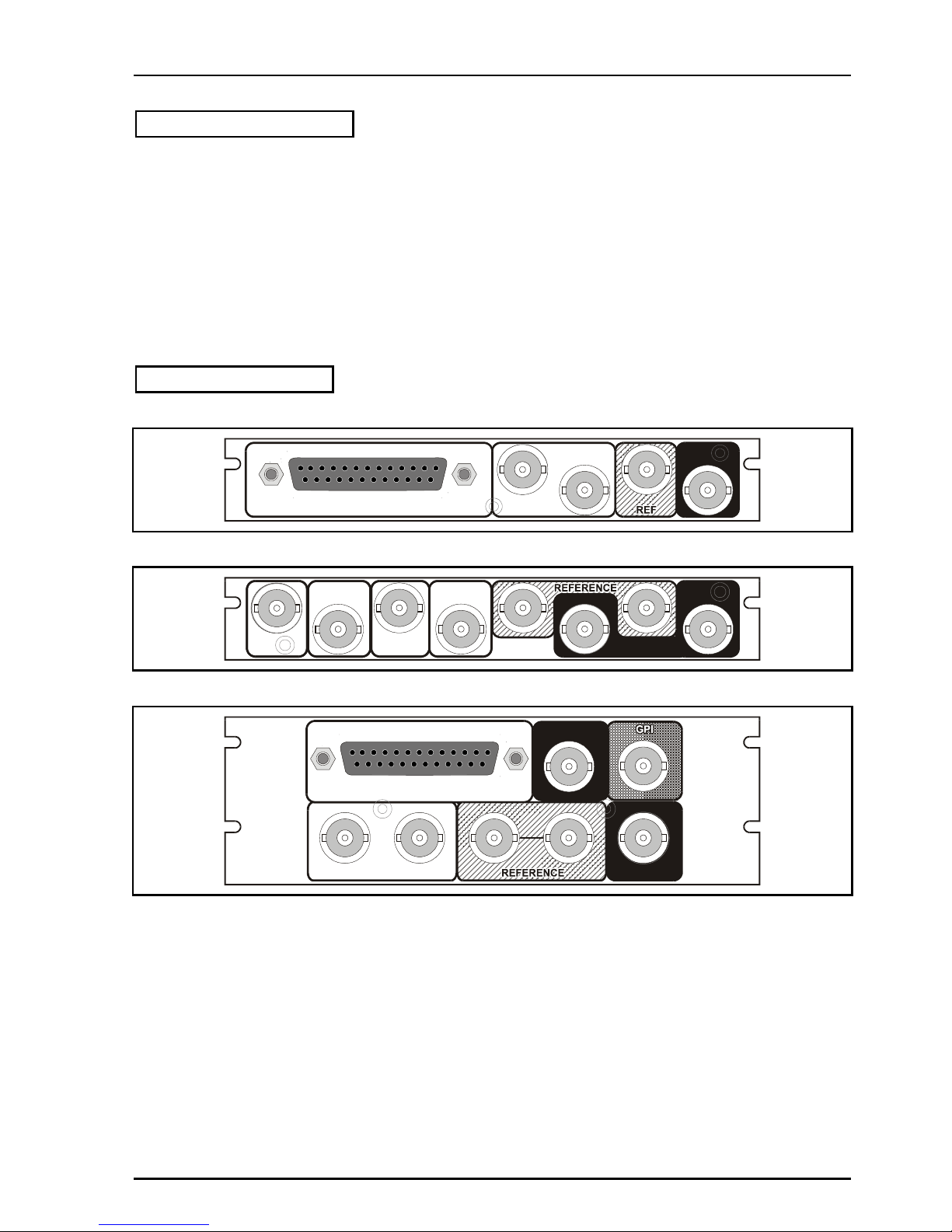
Rear Panel Views
IQDMX0315-1A
AES AUDIO OUT
SERIAL
OUT
1
2
SERIAL
IN
I
Q
D
M
X
0
/
1
_
1
5
1
A
IQDMX0101-1A
SER OUT
SERIAL
IN 2
SER OUT
IQDMX0
_01-1A
2 1
SERIAL
IN 1
AES OUT
1
AES OUT
2
iQDMX0217-2A, IQDMX0217-2A
SERIAL IN 2
AES AUDIO OUT
12
SERIAL IN 1
SERIAL OUT
I
Q
D
M
X
0
/
1
_
1
7
2
A
Page 3
IQDMX01/03/11/13 B5
IQDMX01OPS 05/04/07 www.snellwilcox.com Version 1 Issue 12 B5.3
IQDMX0103-2A, IQDMX0006-2A
AES OUT
2
1
SERIAL IN 2
2
1
IQDMX0
_03-2A
SERIAL OUT
SERIAL IN 1
IQDMX0006-2A
SERIAL IN
2 1
AES OUT
1
3
4
2
SERIAL OUT
IQDMX1
_06-2A
2 1
IQDMX0216-2, IQDMX0216-2
IQDMX0/1
_16-2
AES AUDIO OUT
12
SERIAL IN 1
SERIAL OUT REFERENCE
GPI
SERIAL IN 2
IQDMX0102-2
REFERENCE
IQDMX0
_02-2
GPI
AES OUT
2
1
2
1
SERIAL OUT
SERIAL IN 1
GPI
SERIAL IN 2
Page 4

IQDMX01/03/11/13 B5
IQDMX01OPS 05/04/07 www.snellwilcox.com Version 1 Issue 12 B5.4
Versions of the module cards available are:
Order codes for IQH3A enclosures
IQDMX0101-1A SDI and 4 channel AES demultiplexer with extended video delay. Unbalanced AES
connection. 2 SDI inputs, 2 AES outputs, 2 SDI outputs
IQDMX0103-2A SDI and 4 channel AES demultiplexer with extended video delay. Unbalanced AES
connection. 2 SDI inputs, 2 AES outputs, 2 SDI outputs, 1 GPI
IQDMX0315-1A SDI and 4 channel AES demultiplexer with extended video delay. Balanced AES connection.
1 SDI input, 2 AES outputs, 2 SDI outputs
IQDMX1315-1A SDI and 8 channel AES demultiplexer with extended video delay. Balanced AES connection.
1 SDI input, 4 AES outputs, 2 SDI outputs
IQDMX1317-2A SDI and 8 channel AES demultiplexer with extended video delay. Balanced AES connection.
2 SDI inputs, 4 AES outputs, 2 SDI outputs, 1 GPI
IQDMX0317-2A SDI and 4 channel AES demultiplexer with extended video delay. Balanced AES connection.
2 SDI inputs, 2 AES outputs, 2 SDI outputs, 1 GPI
IQDMX1106-2A SDI and 8 channel AES demultiplexer with extended video delay. Unbalanced AES
connection. 2 SDI inputs, 4 AES outputs, 2 SDI outputs, 1 GPI
IQDMX0317-2A SDI and 4 channel AES demultiplexer with extended video delay. Balanced AES connection.
2 SDI inputs, 2 AES outputs, 2 SDI outputs, 1 GPI
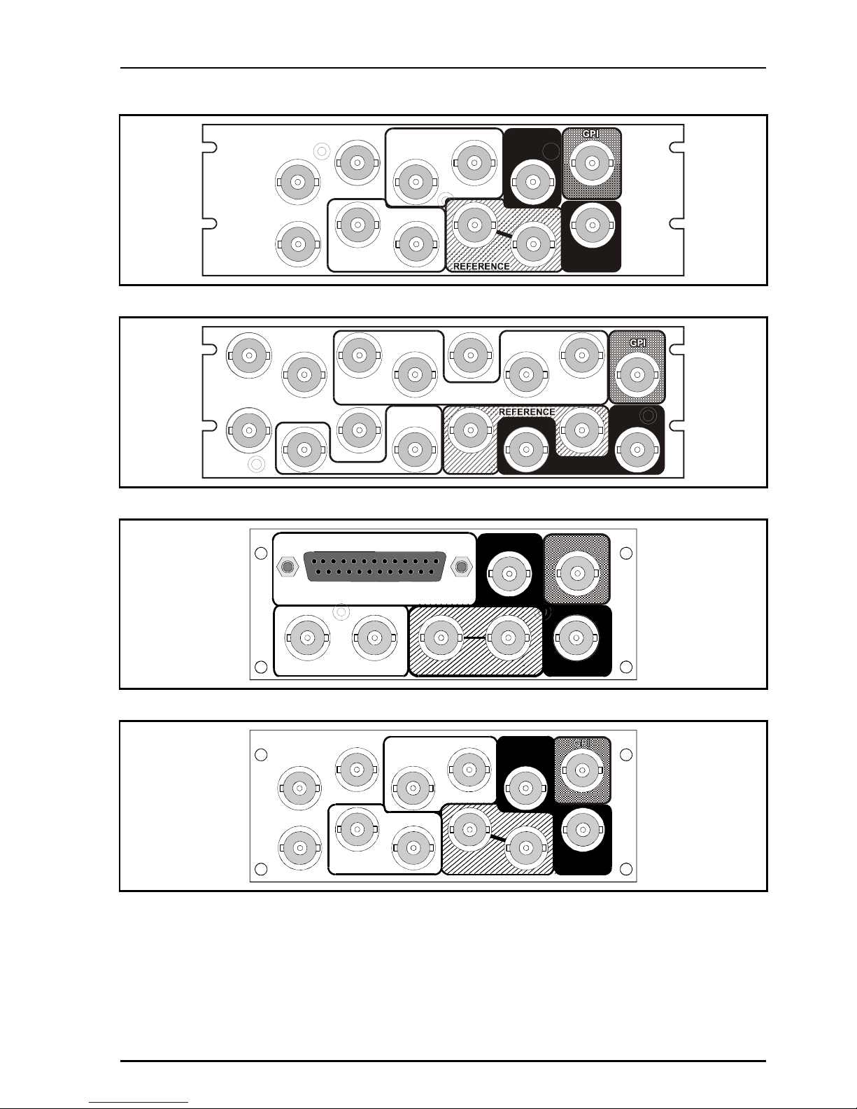
Order codes for other enclosures
IQDMX0316-2 SDI and 4 channel AES demultiplexer with extended video delay. Balanced AES connection. 2
SDI inputs, 2 AES outputs, 2 SDI outputs, 1 GPI
IQDMX0102-2 SDI and 4 channel AES demultiplexer with extended video delay. Unbalanced AES connection.
2 SDI inputs, 2 AES outputs, 2 SDI outputs, 1 GPI
IQDMX1316-2 SDI and 8 channel AES demultiplexer with extended video delay. Balanced AES connection. 2
SDI inputs, 4 AES outputs, 2 SDI outputs, 1 GPI
Product Comparison
AES Outputs
Product
SDI
Inputs
Number Type
SDI
Outputs
GPI
Width &
Style
IQDMX0101-1A 2 2 U/B 2 Single A
IQDMX0315-1A 1 2 BAL 2 Single A
IQDMX1315-1A 1 4 BAL 2 Single A
IQDMX0103-2A 2 2 U/B 2 1 Double A
IQDMX1106-2A 2 4 U/B 2 1 Double A
IQDMX0317-2A 2 2 BAL 2 1 Double A
IQDMX1317-2A 2 4 BAL 2 1 Double A
IQDMX0317-2A 2 2 BAL 2 1 Double A
IQDMX0102-2 2 2 U/B 2 1 Double O
IQDMX0316-2 2 2 BAL 2 1 Double O
IQDMX1316-2 2 4 BAL 2 1 Double O
Page 5
IQDMX01/03/11/13 B5
IQDMX01OPS 05/04/07 www.snellwilcox.com Version 1 Issue 12 B5.5
Note that there are two styles of rear panels available. They are not interchangeable between the two
styles of enclosures. However, the cards may be fitted into any style of enclosure.
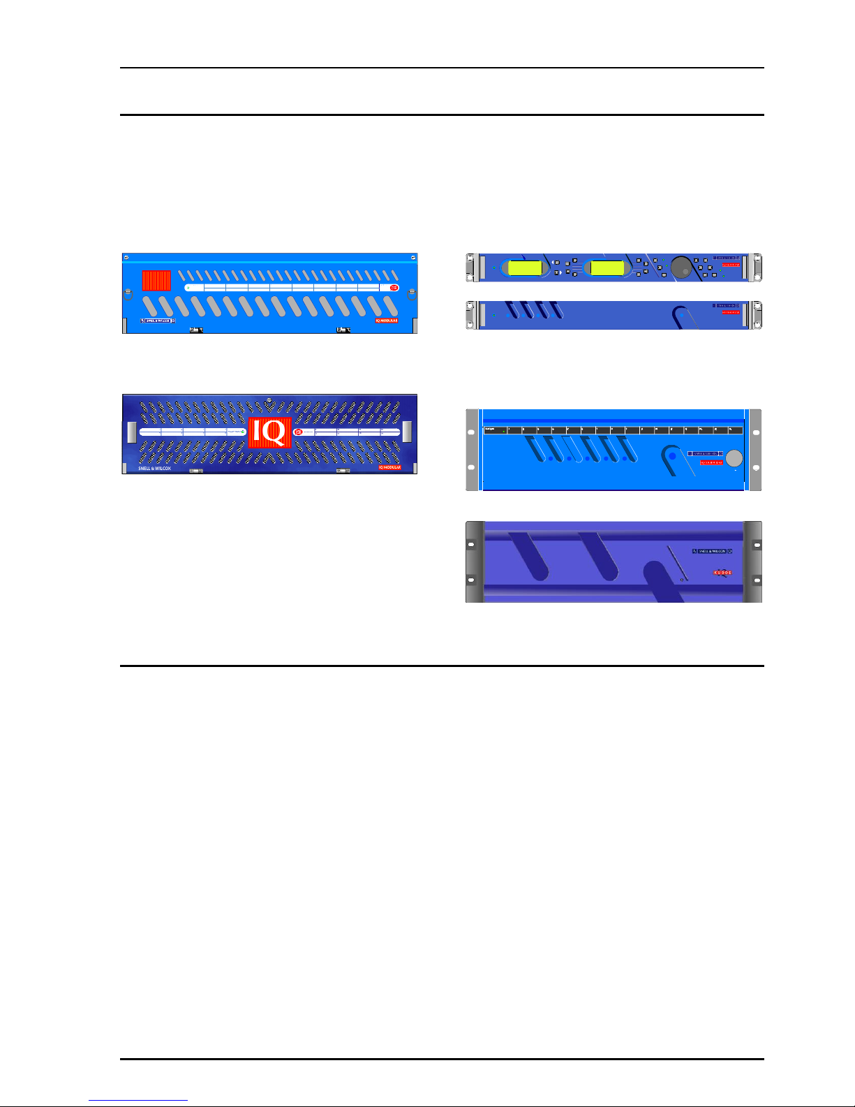
‘A’ Style Enclosure
Rear panels with the suffix A may only be fitted
into the ‘A’ style enclosure shown below.
IQ
(Enclosure order codes IQH3A-E-0, IQH3A-E-P,
IQH3A-0-0, IQH3A-0-P)
(Enclosure order codes IQH3A-S-0, IQH3A-S-P)
‘O’ Style Enclosures
Rear panels without the suffix A may only be fitted
into the ‘0’ style enclosures shown below.
setup
lock save
recall
modules help
adjust
scroll
power
previous
return
home
control
information
display
select
power
(Enclosure order codes IQH1S-RC-0, IQH1S-RCAP, IQH1U-RC-0, IQH1U-RC-AP, Kudos Plus
Products)
power
OPEN
(Enclosure order codes IQH3N-0, IQH3N-P)
(Enclosure order codes IQH3U-RC-0, IQH3U-RC-P)
Page 6
IQDMX01/03/11/13 B5
IQDMX01OPS 05/04/07 www.snellwilcox.com Version 1 Issue 12 B5.6
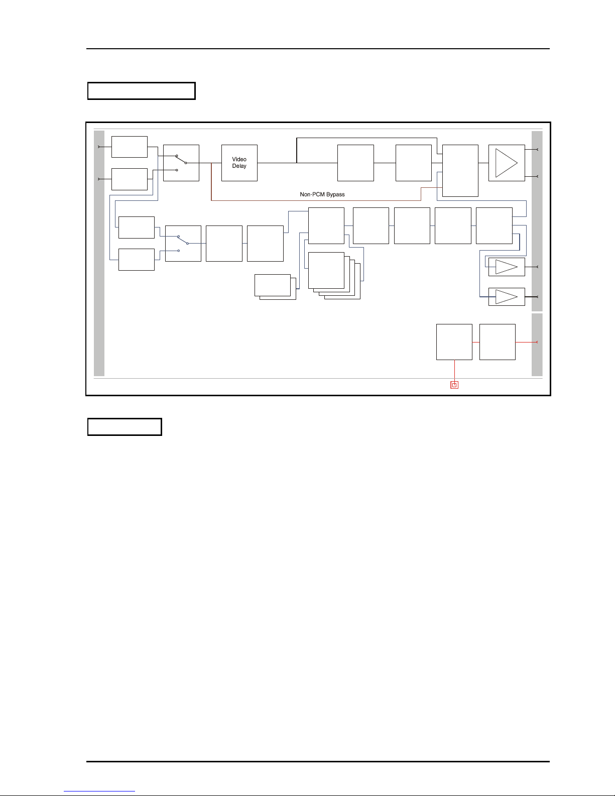
Block Diagram
O
u
t
p
u
t
s
Inputs
SDI RX &
Equalisation
Video
Proc. Amp
SDI TX
Selective
Ancillary
Blanking
SDI RX &
Equalisation
I
/
O
GPI Control
and
TTL Pulse I/O
Built-in
Intelligence
Ancillary data bypass
Network control monitoring
intelligence, and
Demux
Demux
Channel
Router
Audio
Tracking
Delay
Assignable
Audio
Mixers
Assignable
Audio
Mixers
Assignable
Audio
Mixers
Assignable
Audio
Mixers
Audio
Firewall
Tone
Generator
Tone
Generator
Additional
Delay
Signal
Monitoring
1 X GPI
1
2
1
2
AES TX
AES TX
1
2
Ancillary
Data
Multiplexer
Channel
Proc. Amp
Channel
Proc. Amp
Features
•
4/8 channel AES/EBU demultiplexer
•
Can de-embed AES/EBU and AC3 digital
audio data
•
Handles up to 24 bit embedded audio present
on the incoming SDI stream, and deembeds/embeds to 20 bits
•
Flexible audio delay including common fixed
delay and tracking delay
•
A further audio delay of up to 0.5s which
seamlessly tracks the video delay or external
RollTrack / GPI inputs
•
Firewall for processed PCM audio to provide a
continuous output
•
Transparent to non-PCM audio
•
Eight channel audio processor with channel
level manipulation
•
Channel level (Sub-frame) routing
•
4 off 4 channel audio mixers
•
Video proc-amp (gain, saturation, black level)
•
Video test pattern generator, 2 channel audio
tone generator
•
Up to 3 frames of video delay
•
RollCall control and monitoring compatible
Page 7

IQDMX01/03/11/13 B5
IQDMX01OPS 05/04/07 www.snellwilcox.com Version 1 Issue 12 B5.7
Resolution of Audio Processing
Output Audio Format
Input Audio Format
AES SDI embedded
SDI embedded
Pass-through
SDI embedded non-PCM 20 20-bit 20-bit 20-bit
SDI embedded non-PCM 24 Not supported (1) Not supported (1)
24-bit
SDI embedded PCM 20 20-bit 20-bit 20-bit
SDI embedded PCM 24 20-bit (2) 20-bit (2) 24-bit
Notes:
1. Processing input formats that are not supported may produce corrupted output signals.
2. For some signals the output resolution may be less than the input resolution.
Page 8

IQDMX01/03/11/13 B5
IQDMX01OPS 05/04/07 www.snellwilcox.com Version 1 Issue 12 B5.8
Technical Profile
Signal Inputs
Digital Video .......................2 x SDI (BNC) (1 x SDI – single
width versions)
Standards...........................SMPTE 259M-C-1997, SMPTE
272M-A-1994
Signal Outputs
Digital Video .......................SDI x 2
Unbalanced digital audio.....2/4 x AES/EBU, AC3, Dolby E
(BNC)
Balanced digital audio ....... 2/4 x AES/EBU, AC3, Dolby E (25
Way D-Type)
Standards .......................... SMPTE 259M-C-1997, SMPTE
272M-A-1994, AES3-1992
Control Interface
GPI .................................... 1x Closing contact I/O interface
(BNC)
Card Edge Controls
NONE
Card Edge Indicators
SDI Input Loss....................Loss = Off, Good = Green
SDI Input Error.................... Yellow = Unused input not at
current operating standard
CPU running / Power..........One green LED, flashing = OK
RollCall Functions
Audio Controls
Audio extraction select........SDI input 1/2/Follow Video Control
Set headroom.....................4 to 24 dB in 1 dB steps
Set audio detector thresholds
High and low levels, time delay
Input side control proc. - audio gain and polarity
Independent Gain, Mute, Polarity
control over de-embedded audio.
+18 dB to –18 dB in 0.1 dB steps.
Channel routing .................Output channels routed from test
tone, silence or SDI 8 embedded
channels from any group
Output side control proc. - gain and polarity
Independent Gain, Mute, & Polarity
control over embedded and AES
output channels. +18 dB to –18 dB
in 0.1 dB steps.
Global delay offset..............up to +1.5 s in 1 ms steps, common
to all processed audio.
Variable audio delay control source
Up to 0.5 s from RollTrack + GPI
Tone frequency, amplitude & Ident
2-channel tone generator. 100 Hz
to 15 kHz in 100 Hz steps.
Tone Setup:
Frequency .......................... 100 Hz to 15 kHz in 100 Hz steps
Channel Ident .....................0.5 s interruption every 2 s
Video Controls
Select primary input............1/2
Black Level.........................± 100 mV in 0.8 mV steps
Y/C Timing ........................ ± 592 ns in 148 ns steps
Picture position ................. ± 592 ns in 148 ns steps
Luminance Gain................. ± 6 dB
Chrominance Gain............. ± 6 dB
Video Horizontal Delay ...... +1 Line in 37 ns steps
Video Vertical Delay........... +1 Frame in 1 line steps
Video Delay Frames .......... 0 to +2 frames
Other Controls
Pass vertical data .............. On/Off (lines selectable 7/11 to
23/21 & 320/274 to 335/283)
Preset Unit......................... Returns all settings to default
Pattern Select .................... 100%/75% Bars, Multiburst, Black,
Animated Bars
User Memories .................. Name, clear, save and read 8 user
memories
Default Video Output.......... Pattern / freeze/ run through
Default Audio Output.......... Silence
Caption Output .................. On/Off (default and pattern output
only)
Caption Generator ............. Programmable up to 19 characters
GPI/O set-up...................... May be attached to any memory
function/polarity
Reporting (* also Logged)
EDH (for selected input)..... *Presence, *Error-Time, *Error-
Seconds
No SDI .............................. *No input present
Input ancillary error............ ANC error, ANC error-seconds
Input error.......................... Unused input not at current
operating standard
Report Embedded Audio Data
Report audio data pairs on input
and output SDI
Audio Silence, High Level, Low Level, Overflow
For processed audio channels only
RollTrack Input
Delay ................................. Audio delay – Fixed, RollTrack +
fixed
Page 9

IQDMX01/03/11/13 B5
IQDMX01OPS 05/04/07 www.snellwilcox.com Version 1 Issue 12 B5.9
RollTrack Output
Delay..................................Current video/audio delay
Input state...........................Selected Input: Input Present, Input
Missing, Standard 525, Standard
625
Input 1: Input Present, Input
Missing, Standard 525, Standard
625
Input 2: Input Present, Input
Missing, Standard 525, Standard
625
GPI 1 Low, High, Inactive
Embedded Audio state .......De-embed 1-8 Lost/Present
Specifications
Video Internal Processing... 4:2:2 with 10 bit data paths
Serial Input Return Loss .....Better than 15 dB to 270 MHz
Maximum Input Cable length
> 200 m (PSF1/2 or equiv. cable)
Serial Output Level .............800 mV ±5%
Output Overshoot ...............< 70 mV
Output Return Loss.............Better than 15 dB to 270 MHz
Output Jitter........................< 0.2 UI (with 10 Hz High pass filter
selected on 601 monitor)
Minimum Delay ..................6 µs
Delay (Delay Mode)............6 µs - 3 Frames + 5.5 µs
THD+N ...............................< -117 dB @ 700 Hz (24 bits) AES
to AES
Digital Audio Output (Balanced)
Connector/Format............... 25 W D
Level...................................3 V p-p typical into 110 Ohms
Digital Audio Output (Unbalanced)
Connector/Format............... BNC
Level...................................1 V p-p typical into 75 Ohms
Power Consumption
Module Power Consumption
7.5 W max
Page 10
IQDMX01/03/11/13 B5
IQDMX01OPS 05/04/07 www.snellwilcox.com Version 1 Issue 12 B5.10
INPUT CONNECTIONS
Serial Digital Video Inputs
Serial digital inputs are made to the unit via BNC
connectors which terminate in 75 Ohms.
SERIAL
IN
SERIAL
IN 2
SERIAL
IN 1
SERIAL IN
2 1
SERIAL IN 2
SERIAL IN 1
Page 11
IQDMX01/03/11/13 B5
IQDMX01OPS 05/04/07 www.snellwilcox.com Version 1 Issue 12 B5.11
Reference
These connectors have no function on these
modules.
SERIAL
IN 2
SERIAL
IN 1
Page 12
IQDMX01/03/11/13 B5
IQDMX01OPS 05/04/07 www.snellwilcox.com Version 1 Issue 12 B5.12
OUTPUTS
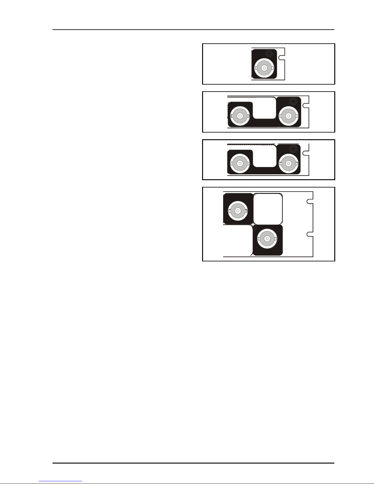
Serial Digital Video Outputs
These are the Serial Digital outputs of the unit via
BNC connectors for 75 Ohms.
GPI I/O (not available on -1A versions)
This connector is used for accepting GPI
information (from mechanical switch contacts,
relay contacts etc.) The resulting action that the
unit takes may be programmed via RollCall.
It may also be configured as an output.
SERIAL
OUT
1
2
SER OUT
SER OUT
2 1
AES OUT
1
12
SERIAL OUT
2
1
SERIAL OUT
SERIAL OUT
2 1
Page 13
IQDMX01/03/11/13 B5
IQDMX01OPS 05/04/07 www.snellwilcox.com Version 1 Issue 12 B5.13
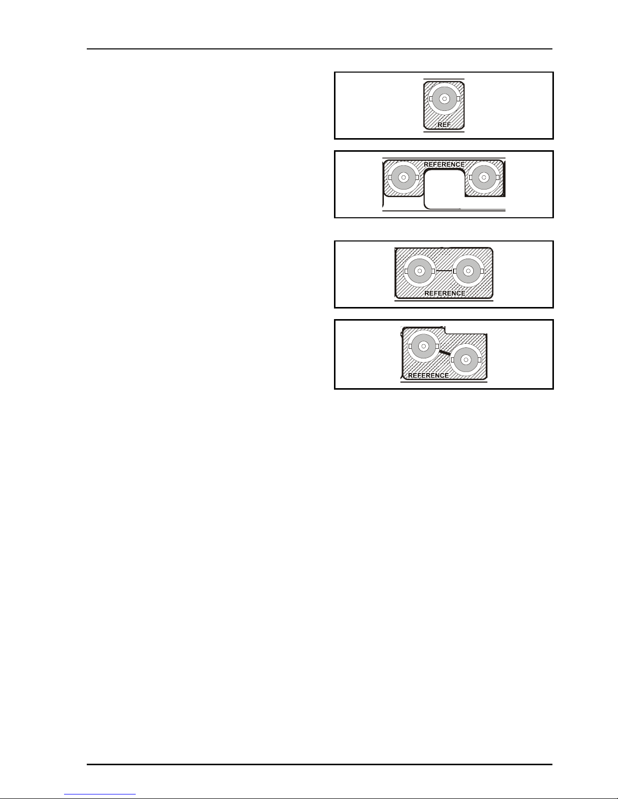
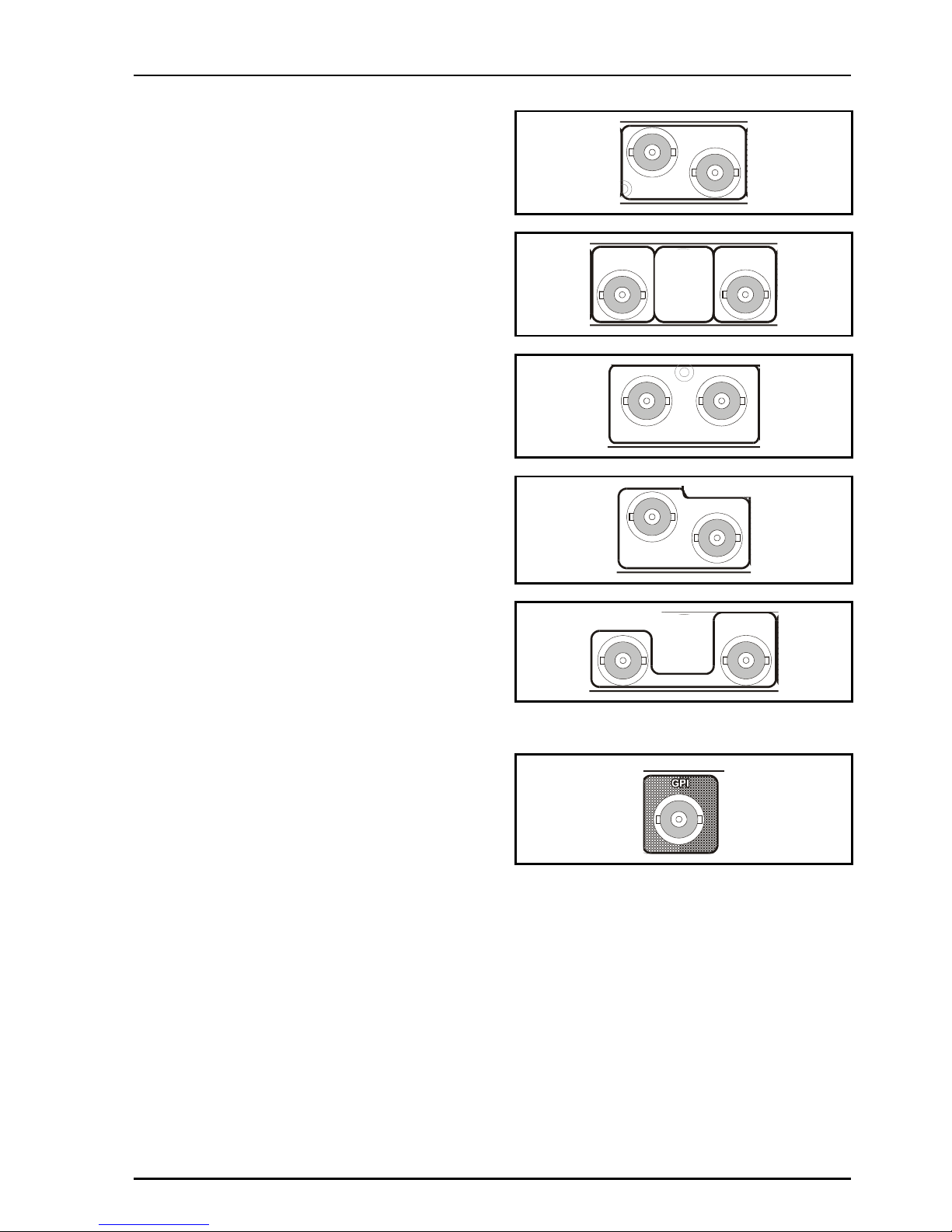
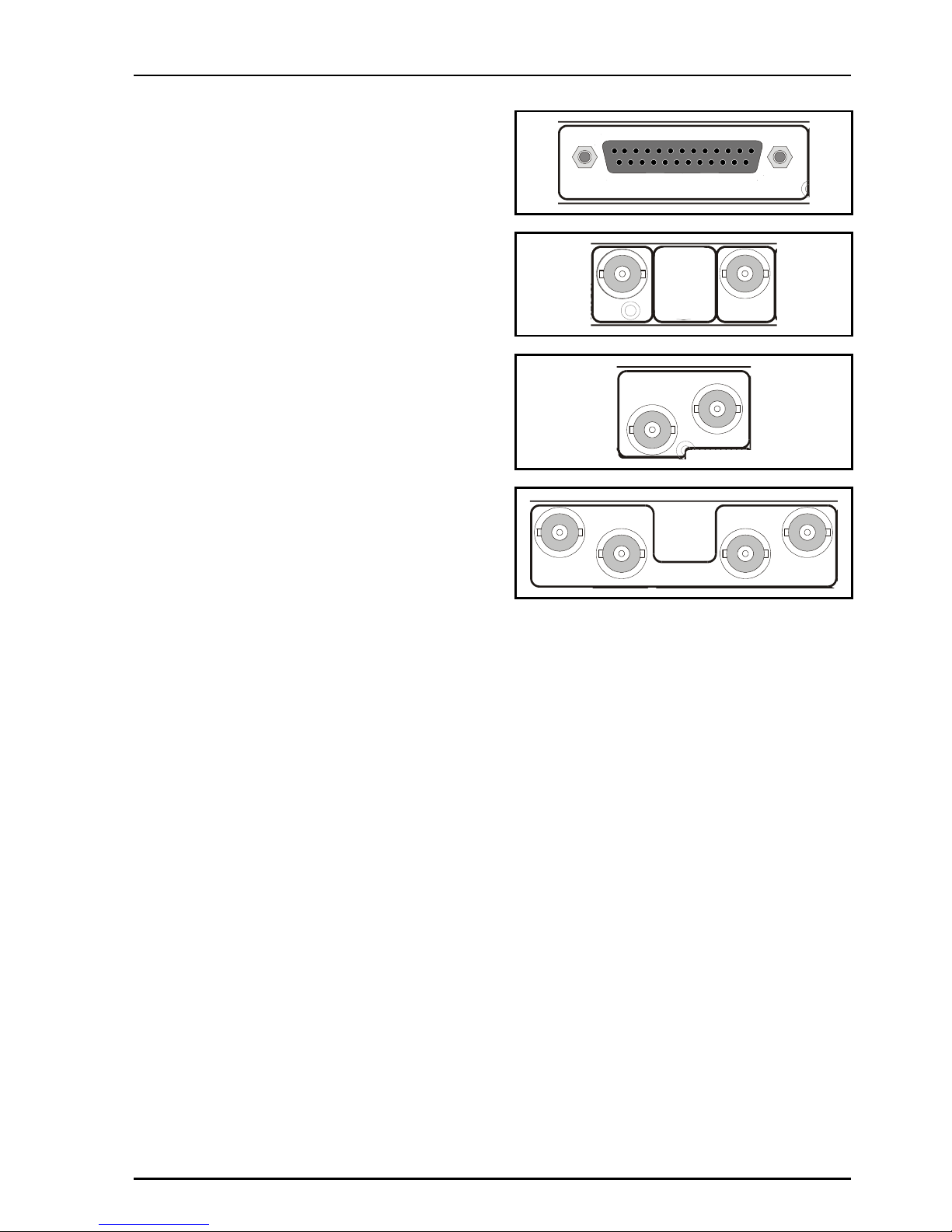
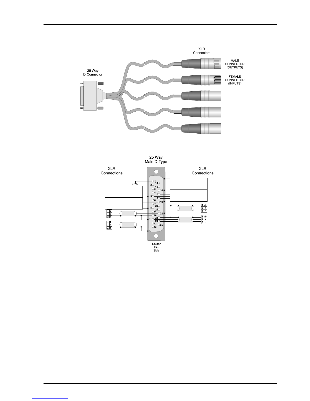
AES Outputs
All balanced AES outputs are available via a 25
way D type connector.
All unbalanced AES outputs are available via BNC
connectors for 75 Ohms.
AES AUDIO OUT
SER OUT
2
AES OUT
1
AES OUT
2
AES OUT
2
1
AES OUT
1
3
4
2
Page 14

IQDMX01/03/11/13 B5
IQDMX01OPS 05/04/07 www.snellwilcox.com Version 1 Issue 12 B5.14
25 Way D Type Connection Details
25 Way D Connector
Pin Number
AES Outputs Standard Pin Assignment
1 CHASSIS
14 GND1
2 1+
15 1-
3 2+
16 2-
4 GND2
17 GND3
5 3+
18 3-
6 4+
19 4-
7 GND4
20 AES OUT 4 Ground GND5
8 AES OUT 4 + 5+
21 AES OUT 4 - 5-
9 AES OUT 3 + 6+
22 AES OUT 3 - 6-
10 AES OUT 3 Ground GND6
23 AES OUT 2 Ground GND7
11 AES OUT 2 + 7+
24 AES OUT 2 - 7-
12 AES OUT 1 + 8+
25 AES OUT 1 - 813 AES OUT 1 Ground GND8
Page 15
IQDMX01/03/11/13 B5
IQDMX01OPS 05/04/07 www.snellwilcox.com Version 1 Issue 12 B5.15
Example of Connection Details to XLR Connectors
AES Out 3
AES out 1
AES Out 4
AES Out 2
Do Not Use
Do Not Use
Do Not Use
Do Not Use
Page 16
IQDMX01/03/11/13 B5
IQDMX01OPS 05/04/07 www.snellwilcox.com Version 1 Issue 12 B5.16
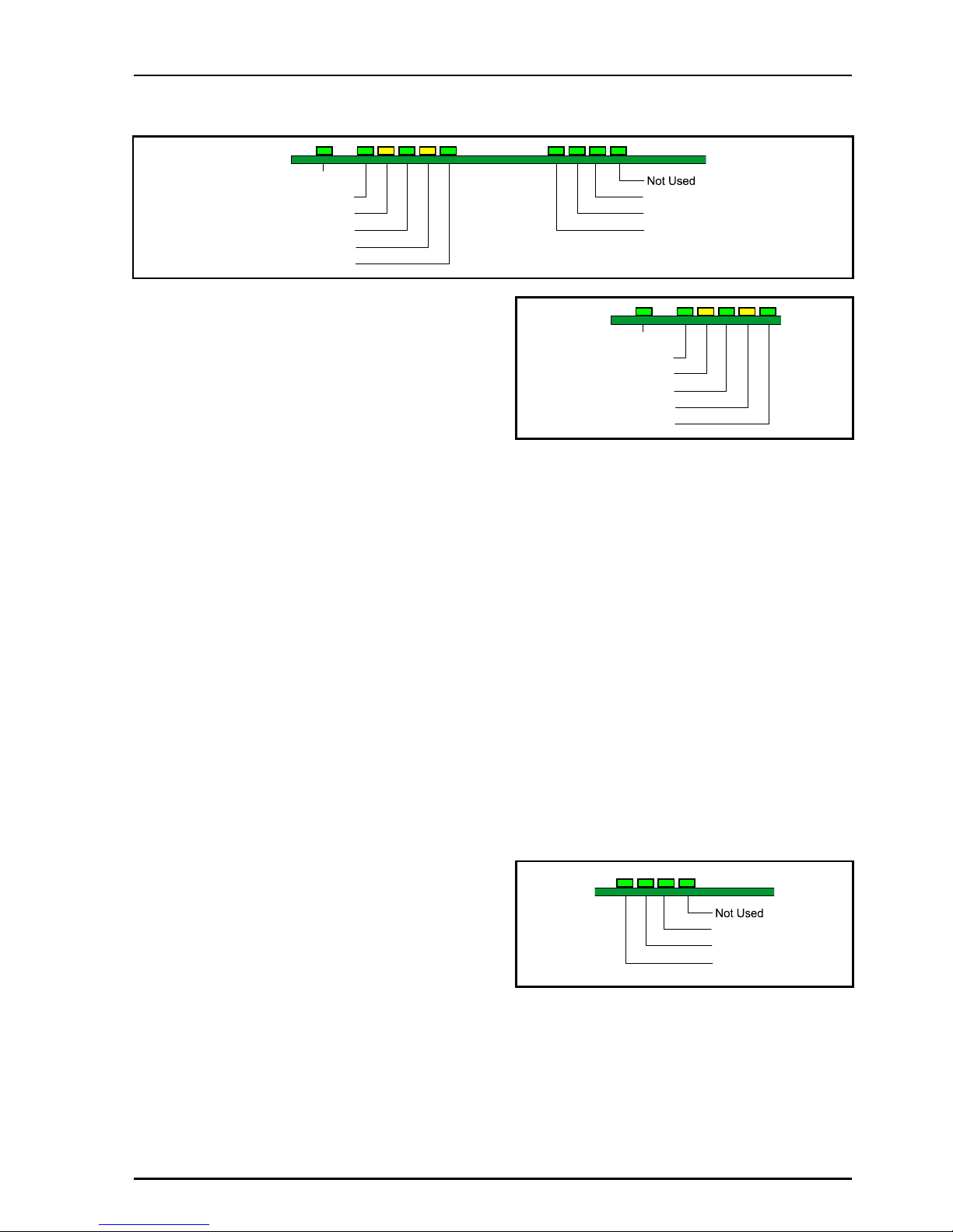
CARD EDGE INDICATORS
SDI 1 Present
CPU Run
SDI 1 Error
SDI 2 Present
SDI 2 Error
Ref Present
Not Used
Not Used
Not Used
Note that only the LED's associated with the
particular version of the product will be active.
CPU Run (Green)
This LED will flash to indicate that the CPU is
running.
SDI 1 Present (Green)
When illuminated this indicates that there is a valid
signal at SDI 1 input.
SDI 1 Error (Yellow)
When illuminated this indicates that SDI 1 input is
not at the current operating standard.
SDI 2 Present (Green)
When illuminated this indicates that there is a valid
signal at SDI 2 input.
SDI 2 Error (Yellow)
When illuminated this indicates that SDI 2 input is
not at the current operating standard.
Ref Present (Green)
This has no function on this unit.
Green x 4
These LED's have no function on this unit.
SDI 1 Present
CPU Run
SDI 1 Error
SDI 2 Present
SDI 2 Error
Ref Present
Not Used
Not Used
Not Used
Page 17
IQDMX01/03/11/13 B5
IQDMX01OPS 05/04/07 www.snellwilcox.com Version 1 Issue 12 B5.17
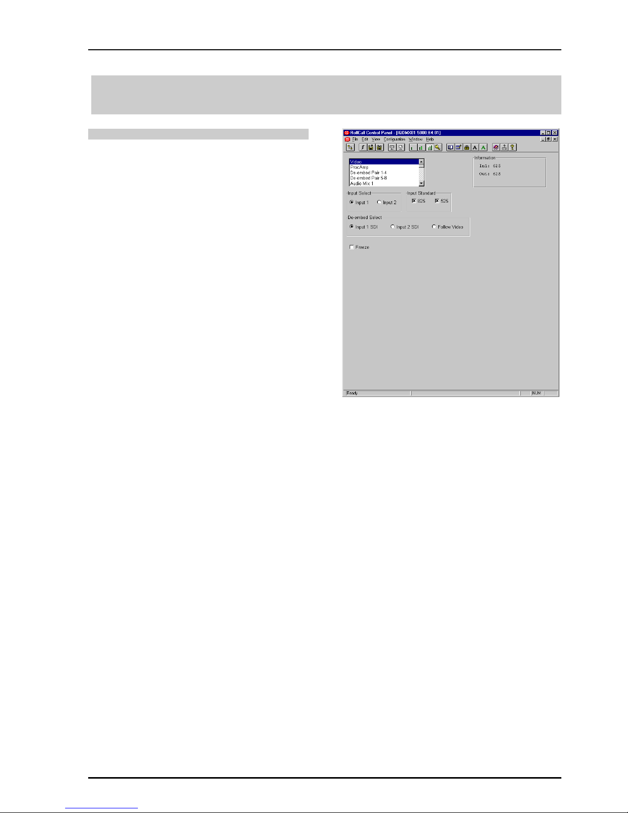
RollCall PC Control Panel Screens
Video
Input Select
This allows either Input 1 or Input 2 to be selected
for processing.
Note that as the IQMUX0315-1A and
IQDMUX1315-1A versions have only one input,
Input 1 should always be selected. If Input 2 is
selected the unit will report an input loss.
Input Standard
This allows input standard to be selected.
If only 625 is selected the unit will be forced to only
accept 625 line inputs.
If only 525 is selected the unit will be forced to only
accept 525 line inputs.
If 625 and 525 are selected the unit will accept
both 625 and 525 line inputs.
DeEmbed Select
Either Input 1 SDI or Input 2 SDI may be selected
for DeEmbedding. If Follow Video is checked the
signal selected via the Input Select item will be
DeEmbedded.
Non-PCM groups can be transparently passed but
if a non-PCM group is selected for mixing or
routing it will be automatically muted.
If a Dolby header is detected in the data stream it
will be processed as a non-PCM signal.
Freeze
When checked the output picture will become a
frozen frame.
Page 18
IQDMX01/03/11/13 B5
IQDMX01OPS 05/04/07 www.snellwilcox.com Version 1 Issue 12 B5.18
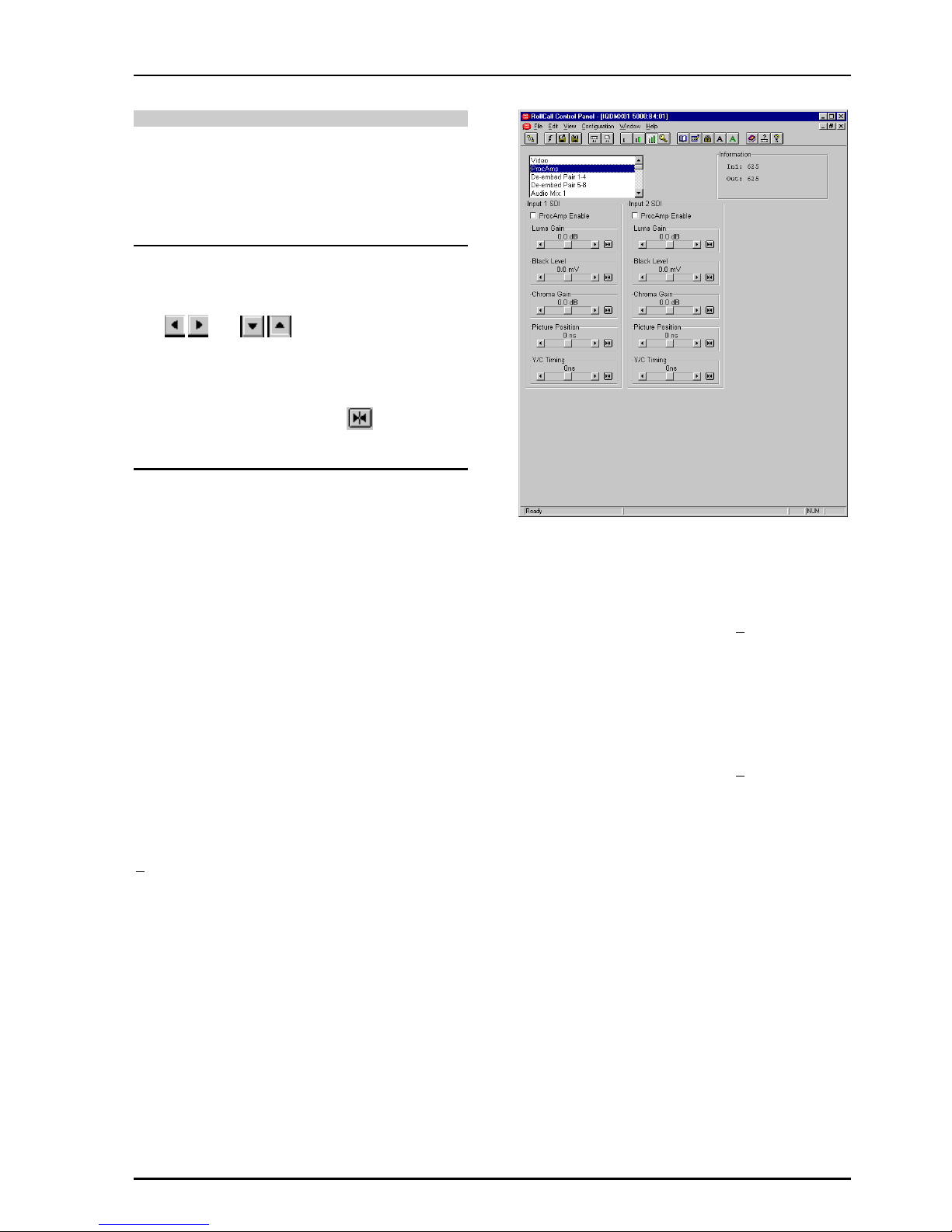
ProcAmp
These items allow signal levels and timings to be
adjusted.
Separate adjustments may be made for the two
input channels Input 1 SDI and Input 2 SDI.
Note that for this and other screens the following
applies to the scroll bars:
The and symbols at the ends of the
scroll bar allow the value to be adjusted in discrete
steps.
The numerical value will be shown next to the
scroll bars and selecting Preset will return the
setting to the calibrated value for that item.
Input 1 SDI and Input 2 SDI Controls
These items allow the gain, black level and timing
of both signals to be adjusted.
ProcAmp Enable
When checked the ProcAmp will become enabled
for that channel and the settings will be applied to
the signal.
When unchecked the settings will revert to the
preset values.
Luma Gain
This allows the Y (luminance) gain to be adjusted
by ±6 dB in steps of 0.1 dB. Preset value is 0.0 dB.
Black Level
This allows the black level to be adjusted by
+100mV in 0.8mV steps. Preset value is 0.
C Gain
This allows the Cb/Cr (color difference) gain to be
adjusted by ±6 dB in steps of 0.1 dB. Preset value
is 0.0 dB.
Picture Position
This item allows the timing of the picture position
relative to the normal value, to be adjusted.
The timing may be adjusted by +592ns in 148ns
steps.
Y/C Timing
This item allows the timing of the chrominance
signal relative to the luminance signal to be
adjusted, (i.e. Y to Cb/Cr timing) in nanoseconds.
The timing may be adjusted by +592ns in 148ns
steps.
Page 19

IQDMX01/03/11/13 B5
IQDMX01OPS 05/04/07 www.snellwilcox.com Version 1 Issue 12 B5.19
De-embed Pair 1-4 and 5-8
This allows control of Gain, Mute, and Polarity over
the de-embedded channel pairs.
L and R
These scrollbars allow the gain of the Left and
Right channels to be adjusted over a range of
±18 dB in 0.1dB steps. Preset is to 0 dB.
Invert
When checked the signal polarity will be inverted.
Mute
When checked the signal will be muted.
Stereo
When checked the left and right channels will be
configured as a stereo pair and any adjustments
made to one channel will automatically be applied
to both channels.
Page 20

IQDMX01/03/11/13 B5
IQDMX01OPS 05/04/07 www.snellwilcox.com Version 1 Issue 12 B5.20
Audio Mix 1, 2, 3 and 4
There are four separate audio mixers Mix 1, 2, 3
and 4.
Each mixer has four inputs with individual gain
controls that allow the mixing levels for each of the
input signals, to be adjusted. The range of
adjustment is from 0 to –90 dB and to Off.
0 to -60 dB is in steps of 1 dB, -60 dB to -90 dB is
in steps of 3 dB.
The inputs can be selected from the list in the
Source 1, 2, 3 and 4 items.
The outputs of these mixers provide four extra
input selections for the Channel Router.
Page 21
IQDMX01/03/11/13 B5
IQDMX01OPS 05/04/07 www.snellwilcox.com Version 1 Issue 12 B5.21
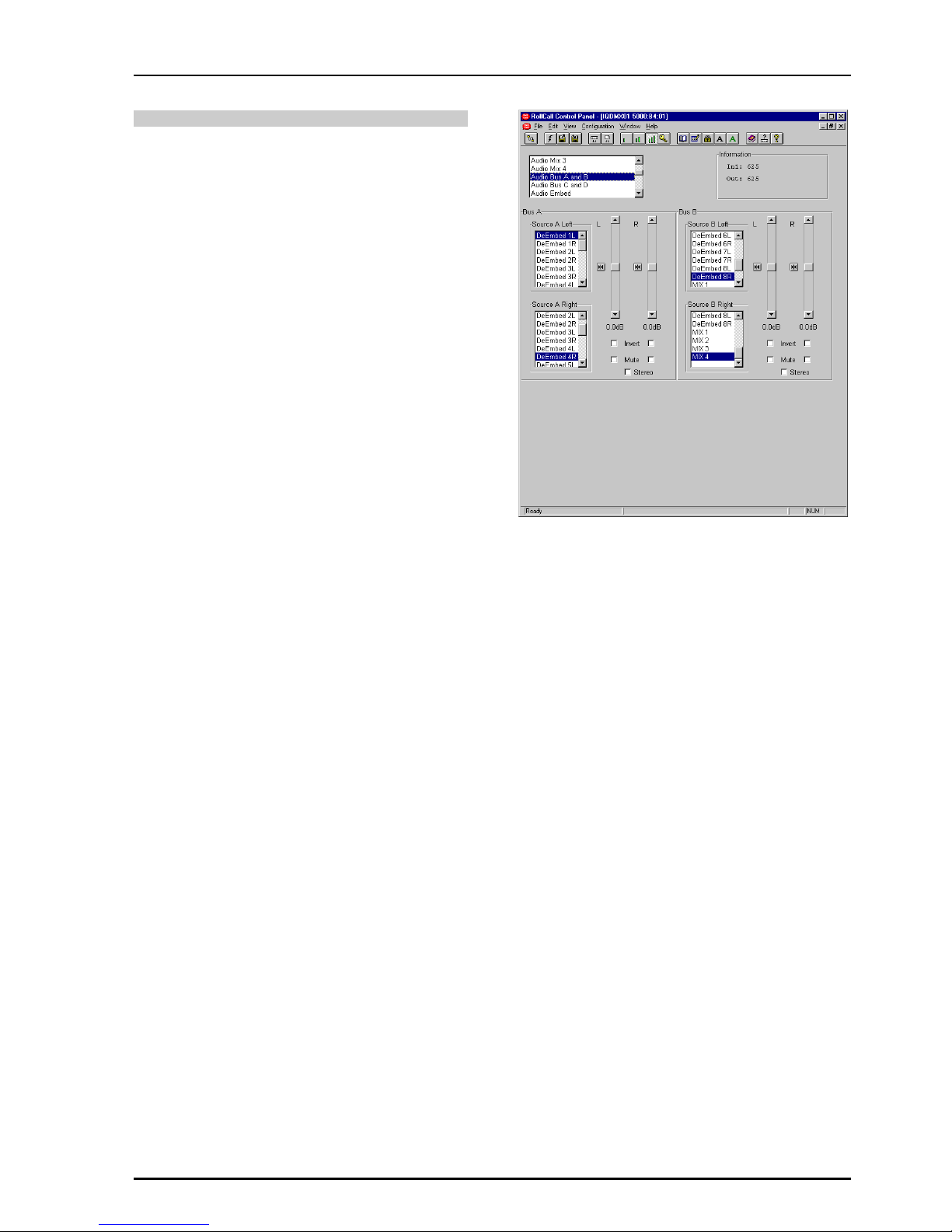
Audio Bus A and B/Audio Bus C and D
This function allows the inputs for the four audio
buses of the router to be selected.
For each bus any source may be selected from the
list for the left and right channels.
L and R
These scrollbars allow the gain to be adjusted over
a range of ±18 dB in 0.1dB steps. Preset is to
0 dB.
Invert
When checked the signal polarity will be inverted.
Mute
When checked the signal will be muted.
Stereo
When checked the left and right channels will be
configured as a stereo pair and any adjustments
made to one channel will automatically be applied
to both channels.
Page 22
IQDMX01/03/11/13 B5
IQDMX01OPS 05/04/07 www.snellwilcox.com Version 1 Issue 12 B5.22
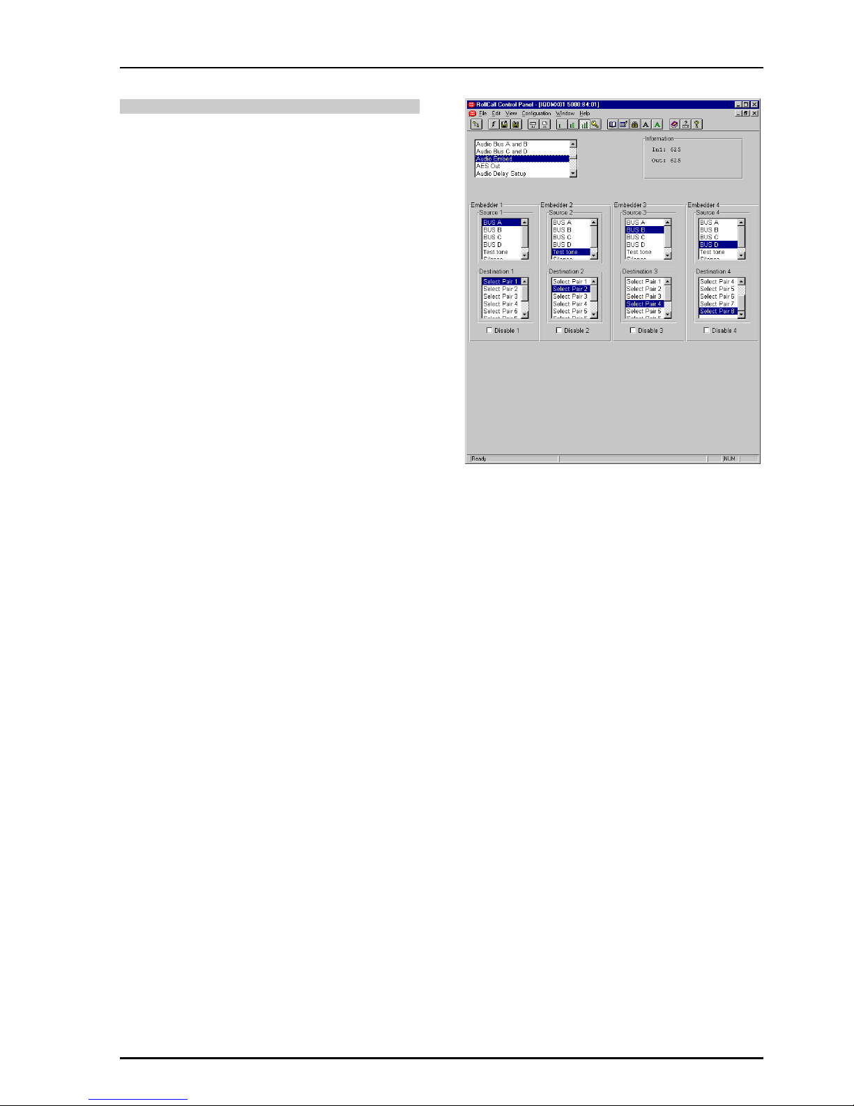
Audio Embed
This function sets up the embedder sources and
destinations. Higher number embedders have
priority, so if the same destination pair is selected
on two embedders, the highest embedder will be
the one that is active.
Embedder 1, 2, 3, and 4
The source of the signal for the embedder may be
selected from the list.
Destination 1, 2, 3, and 4
The destination for the embedded signal may be
selected from the list.
Disable 1, 2, 3 and 4
When checked the embedding will be turned off.
Non-PCM Signals
Note that for non-PCM signals sources both
embedders in the group (Group 1 = Embedder 1 &
2, Group 2 = Embedder 3 & 4) should be disabled.
For details of the Audio Embedding Packet
Distribution please refer to Appendix 2 on page 80.
Page 23

IQDMX01/03/11/13 B5
IQDMX01OPS 05/04/07 www.snellwilcox.com Version 1 Issue 12 B5.23
AES Out
This allows the signal source for the AES output to
be selected from the list of items for the two AES
sources. Silence and audio test tones may also be
selected.
Passing Through Embeded non-PCM Signals
To pass embedded non-PCM signals direct to the
AES output DeEmbed (1 to 8) should be selected
from the Source list.
Note that in this mode all processing will be
bypassed.
Page 24
IQDMX01/03/11/13 B5
IQDMX01OPS 05/04/07 www.snellwilcox.com Version 1 Issue 12 B5.24
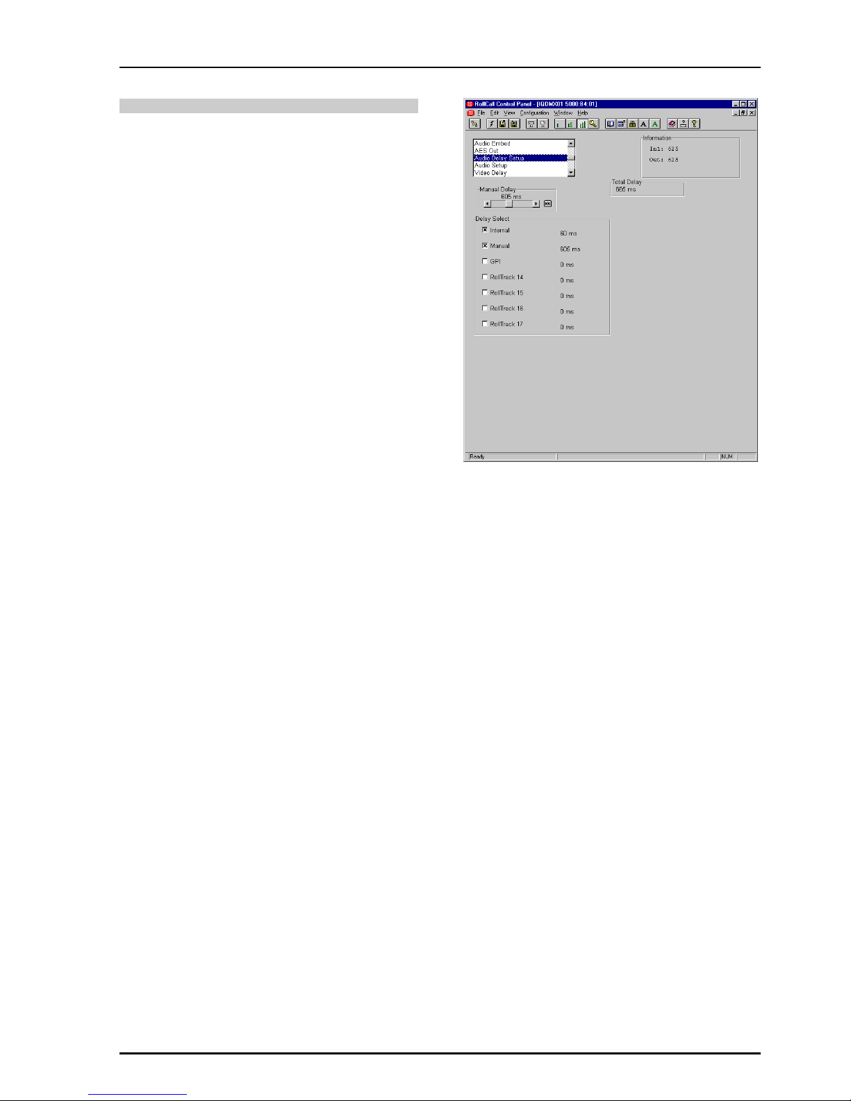
Audio Delay Setup
This screen allows the amount of delay to be set
and type of audio delay mechanism to be selected.
Manual Delay
This will affect all processed audio signals equally.
The delay may be set to up to +1.5 s in 1ms steps.
Delay Select
This allows the type of audio delay mechanism to
be selected. One or more of the types may be
checked. The amount of delay applied will be the
sum of the delay from the enabled delay
mechanisms.
Note that up to 0.5 s of delay may be applied from
the sum of the GPI + RollTrack delay inputs.
Manual
When checked an audio delay set by the Manual
Delay control will be applied.
GPI
When checked an audio delay will be applied that
is equal to the width of the pulse arriving at the
GPI connector.
Note that an audio delay pulse of more than
500 ms, applied to the GPI Input will be treated as
invalid. This will result in the GPI delay returning to
zero.
Note that the GPI must be configured correctly for
this function to operate. Please see page 30 for
details.
RollTrack 14, 15, 16 and 17
Then selected source(s) of the RollTrack input
signal(s) will apply an audio delay.
Total Delay
This will show the audio total delay (due to all
delay mechanisms) through the unit in ms.
Page 25

IQDMX01/03/11/13 B5
IQDMX01OPS 05/04/07 www.snellwilcox.com Version 1 Issue 12 B5.25
Audio Setup
Audio Monitoring
The four audio buses are monitored and level
detectors provide status information and logging
data.
Silence
The level at which the signal is considered to have
dropped to silence may be set with this control.
The range is from -80 dB to 0 dB in steps of 1 dB.
Preset is to -70 dB.
Low Level
The level at which the signal is considered to have
dropped to a Low Level may be set with this
control.
The range is from -80 dB to 0 dB in steps of 1 dB.
Preset is to -60 dB.
High Level
The level at which the signal is considered to have
risen to a High Level may be set with this control.
The range is from -80 dB to 0 dB in steps of 1 dB.
Preset is to -10 dB.
Overload
The level at which the signal is considered to have
risen to an Overload condition may be set with this
control.
The range is from -80 dB to 0 dB in steps of 1 dB.
Preset is to 0 dB.
Warning Timer
All the above monitoring facilities will only operate
after a time interval set by this control. A valid
signal is reported immediately.
The range is from 1 to 20 seconds. Preset is to 10
seconds.
Audio Tone
The frequency of the Audio Test Tone may be set
using this control. Left and right channels may be
set independently.
Frequency L and R
The range is from 100 Hz to 15 kHz in steps of
100 Hz. Preset is to 400 Hz.
Page 26

IQDMX01/03/11/13 B5
IQDMX01OPS 05/04/07 www.snellwilcox.com Version 1 Issue 12 B5.26
Audio Setup (continued)
Ident Enable
When enabled the right channel will be identified
by the signal being muted for 0.5 second every 2.5
seconds.
Headroom
This allows the headroom to be set. The range is
from 4 dB to 24dB in 1 dB steps. Preset is to
18 dB.
Note that in this product headroom is defined as:
Clipping Leve
l
(0 dBFS)
Peak Level
(Operational)
Line-up Level
(0dBu)
Headroom
Headroom = Clipping Level – Line-up level
Audio Slew Select
This is the time taken for the audio to slew when
the audio mixing and routing controls have
changed.
The options are:
Instant ....The response is immediate
Slowest ..Change takes approximately one second
Slow .......Change takes 75% of Slowest time
Medium ..Change takes 50% of Slowest time
Fast........Change takes 25% of Slowest time
Channel Status Dest(ination)
This will set the four character name used in the
destination field of the audio channel status.
To change the text, type the new text in the text
area and then select (return).
Selecting Preset will return the text to the
default text (DEST).
Note that the Channel Status Origin data is
automatically set by the module to DMX1 and
cannot be changed.
Page 27

IQDMX01/03/11/13 B5
IQDMX01OPS 05/04/07 www.snellwilcox.com Version 1 Issue 12 B5.27
Video Delay
H(orizontal) Delay (625/525)
This item allows the horizontal timing of the output
signal relative to the input signal to be adjusted by
up to 1 line in 37 ns steps. The scrollbar will adjust
this value.
Selecting Preset returns the setting to the
minimum horizontal delay.
V(ertical) Delay (625/525)
This item allows the vertical timing of the output
signal relative to the input signal to be adjusted, in
TV lines. The scrollbar will adjust this value. Range
is from 0 to 624 or 524 lines in 1 line steps.
Selecting Preset returns the setting to the
minimum vertical delay.
Video Delay Frames
The number of frames that the output signal will
appear after the input signal may be set with this
item.
Page 28

IQDMX01/03/11/13 B5
IQDMX01OPS 05/04/07 www.snellwilcox.com Version 1 Issue 12 B5.28
VBI & HANC Blank(ing)
This item allows the Vertical Interval data (all or
specific lines) contained in the input signal to be
blanked or passed through the module.
It allows the selection of which vertical interval
lines to pass through to the output and which lines
to blank.
525 Pass
This section allows lines 11 to 21 and lines 274 to
283 of 525 line signals to be selected and passed
through to the output by checking the appropriate
box.
625 Pass
This section allows lines 7 to 23 and lines 320 to
335 of 625 line signals to be selected and passed
through to the output by checking the appropriate
box.
All
This section allows all vertical interval lines to be
selected and either passed to or blanked from the
output signal.
Selecting this item will select all vertical interval
lines in the 525 line list and allow them to passed
through to the output.
Selecting this item will select all vertical interval
lines in the 625 line list and allow them to passed
through to the output.
Selecting this item will select all vertical interval
lines in the 525 line list and blank them from the
output.
Selecting this item will select all vertical interval
lines in the 625 line list and blank them from the
output.
Hanc Blank
When checked all horizontal data will be blanked,
on the input. When unselected, passthrough
operations will not alter audio packets for groups
that the IQDMX01 has not selected for embedding.
In order to allow minimum synchronization delay
the created packets are output first and then the
passthrough groups are placed after the created
streams have been embedded. This means that
passthrough is achieved without altering the input
packet distribution. Passthrough operation has to
take note of marked for deletion packets and these
are removed where possible to ensure that one
does not run out of useable ancillary space.
For details of the HANC Data Handling please
refer to Appendix 2 on page 80.
V Flag (OBD)
This control allows the V(ertical) Flag to be
changed from line 10 (OVD, Optional Video Data)
to line 20 (OBD, Optional Blanking Data).
Unchecked selects OVD and checked selects
OBD. The default is OVD selected.
Note that this function is only active for 525 line
signals.
Page 29

IQDMX01/03/11/13 B5
IQDMX01OPS 05/04/07 www.snellwilcox.com Version 1 Issue 12 B5.29
Caption & Pattern
This function will allow a caption to be edited and
selected and various patterns to be used as the
output signal when the Pattern On function is
selected.
Caption
This function allows control of the caption (white
text on a black background) which may contain a
maximum of 19 characters (including spaces).
The caption will appear in the lower section of the
picture.
Edit caption
To change the caption, type the new text in the
text area and then select (return).
Selecting Preset will return the text to the
default text (IQMUX01).
Select Caption
Caption Off The caption will not appear on the
screen
Caption On The caption will appear on screen
Pattern
Pattern On
When selected the output will become the pattern
selected from the Pattern Select list.
Pattern Select
One of the patterns (including Black) may be
selected from the list.
Animated Pattern
When selected, a monochrome rectangular area
will appear on the output picture as shown
opposite. The brightness of this rectangle will ramp
from black, through gray to white and then directly
to black over a period of about one second. This
action will then be repeated continuously.
This pattern is useful for checking active video
paths. Down stream equipment can see that video
has not been frozen.
Caption Text
Animated Pattern
This is the caption
White
Black
Animated Pattern Brig
htness
~1 Second
Page 30

IQDMX01/03/11/13 B5
IQDMX01OPS 05/04/07 www.snellwilcox.com Version 1 Issue 12 B5.30
GPI
This screen allows the GPI functions to be
configured and their actions defined.
Disable Inputs
When selected all GPI input functions will be
disabled.
Input Functions
When configured as an input the GPI connection
may be used for accepting GPI information (from
mechanical switch contacts, relay contacts etc.)
The resulting action that the unit takes may be
selected using this item.
The GPI input functions that may be selected are
as follows:
Unused The unit will perform no function. This
is also the Preset Setting.
Pattern The unit will produce a pattern chosen
from the Pattern menu when the input
changes from open to closed.
Memory The unit will use the settings in
1 to 8 the selected memory location when
the input changes from open to
closed.
Mem1-2 The unit will toggle between the
settings of memory locations 1 and 2.
Open to Closed = Memory 1 settings
Closed to Open = Memory 2 settings
Mem 3-4 The unit will toggle between the
settings of memory locations 3 and 4.
Open to Closed = Memory 3 settings
Closed to Open = Memory 4 settings
Mem 5-6 The unit will toggle between the
settings of memory locations 5 and 6.
Open to Closed = Memory 5 settings
Closed to Open = Memory 6 settings
Mem 7-8 The unit will toggle between the
settings of memory locations 7 and 8.
Open to Closed = Memory 7 settings
Closed to Open = Memory 8 settings
GPI In Status
This will display the current status of the selected
GPI input.
This may show either High or Low. When low, the
associated function will be triggered.
Page 31

IQDMX01/03/11/13 B5
IQDMX01OPS 05/04/07 www.snellwilcox.com Version 1 Issue 12 B5.31
GPI (continued)
Output Functions
The GPO may be configured to produce an output
corresponding to one of the following conditions:
• Input Present
• Standard 625
• Video Delay
• Unused
The preset setting for the output is to Unused.
When the condition is not true the output will float
but when the condition is true the output is closed
to ground via a transistor.
Note that when video delay mode is selected the
output is a negative going TTL pulse. The width of
the pulse will be 1 millisecond.
GPI Out Status
This will display the current status of the GPI
output. This may show either Unused, High, low or
video delay in milliseconds.
Timer Enable
When checked the GPI will be monitored. The
width of the pulse represents the delay that can be
used to control audio delays in this unit.
Note that an audio delay pulse of more than
500 ms, applied to the GPI Input will be treated as
invalid. This will result in the GPI delay returning to
zero.
Timer Active High
When checked the GPI will measure the positive
going pulse. When unchecked the negative pulse
is measured.
Out Active High
This determines the sense of the asserted GPI
output signal. When checked the GPI is active the
output sense is high. When unchecked the GPI is
active low.
GPI I/O Output Enable
When checked the GPI is configured as an output.
When unchecked the GPI is configured as input.
Page 32

IQDMX01/03/11/13 B5
IQDMX01OPS 05/04/07 www.snellwilcox.com Version 1 Issue 12 B5.32
RollTrack
This function allows information to be sent, via the
RollCall™ network, to other compatible units
connected on the same network.
For example, it can enable compatible audio delay
units to produce an audio delay dependent on this
and other similar units. The audio delay unit will
dynamically follow or track the received delay-time
information. This allows processed video signals to
be timed correctly with audio signals. This
automatic tracking system via the RollCall™
network is call RollTrack.
For more detailed information, see the RollTrack
section (Appendix) at the end of this manual.
RollTrack Index
This item allows up to 70 destinations to be selected.
RollTrack Source
This allows the source of information that triggers the
transmission of data to be selected. Options are:
Unused (off) De-embed 1 Lost
Input Present De-embed 1 PCM
Input Missing De-embed 1 NPCM
Standard 525 to
Standard 625 De-embed 8 Lost
Input 1 Present De-embed 8 PCM
Input 1 Missing De-embed 8 NPCM
Standard 1 525 GPI 1 Low
Standard 1 625 GPI 1 High
Input 2 Present GPI 1 Inactive
Input 2 Missing
Standard 2 525
Standard 2 625
Audio Delay
Video Delay
Note that the GPI RollTrack functions should not
be used when GPI Timer Enable is selected.
The destination for the information is set by the
network code address as follows:
Network Address
This item allows the address of the selected
destination unit to be set.
To change the address, type the new destination
in the text area and then select (return)
(Preset) returns to the default destination
The full RollTrack address has four sets of
numbers
For example: 0000:10:01*362
The first set (0000) is the network segment code
number
The second set (10) is the number identifying the
(enclosure/mainframe) unit.
The third set (01) is the slot number in the unit
The Fourth Set (362)
Each RollCall unit has a unique identification
embedded in the units’ software. In this example
362 represents an IQDMX00, 412 would represent
an IQDEC00, 161 a Mach 1 etc. Inserting this
number in the RollTrack address ensures that only
the correct type of unit (in this example an
IQDMX00) will respond to the RollTrack command;
any other unit will ignore the command.
If this number were set to 00 any type of unit at
this location would respond to the RollTrack
command, possibly causing unpredictable results.
The unit ID of a module on the RollCall network
may be found under RollCall Control
Panel/RollCall Listing/Unit Information or via the
RollCall Control Panel Help/About Current Unit
function.
Page 33

IQDMX01/03/11/13 B5
IQDMX01OPS 05/04/07 www.snellwilcox.com Version 1 Issue 12 B5.33
RollTrack (continued)
RollTrack Command
The full RollTrack command has two sets of
numbers
For example: 84*156
The first set (84) is the RollTrack command
number
Note that only command numbers 14,15,16 and 17
should be used for audio delay
The second set (156) is the value sent with the
RollTrack command number
For details of the RollCall command values for
specific units please contact your local Snell &
Wilcox agent.
Disable All
When this item is checked all RollTrack items will be
disabled.
RollTrack Sending
This item shows when the unit is actively sending
the RollTrack command.
This may show:
String A string value is always being sent.
Number A number value is always being sent.
No The message is not being sent.
Yes The message is being sent.
Internal Inconsistent behavior; please contact
Type Error your local Snell & Wilcox agent.
RollTrack Status
This item will show the status of the currently
selected RollTrack index.
This may show:
OK RollTrack message sent and received
OK.
Unknown Rolltrack message has been sent but
it has not yet completed.
Timeout RollTrack message sent but
acknowledgement not received. This
could be because the destination unit
is not at the location specified.
Error This indicates a broken RollCall state.
Bad This indicates a broken RollCall
packet.
Page 34

IQDMX01/03/11/13 B5
IQDMX01OPS 05/04/07 www.snellwilcox.com Version 1 Issue 12 B5.34
Memories
This function allows a number of particular setups
of the unit to be saved and recalled. There are 8
memory locations available.
To change the memory name, type the new name
in the text area and then select (return).
Selecting Preset will return the text to the
default name.
This item allows the memory location to be cleared
and returned to the default (preset) setting. This
empties the memory location and the Recall button
will then appear grayed out.
This function allows the settings of all items to be
saved at the memory location.
This function allows the settings saved at the
memory location to be recalled. When this button
appears grayed out it indicates that the memory
location is empty and therefore cannot be recalled.
This will occur when the memory is cleared.
Note that all the above functions are a momentary
action.
Page 35

IQDMX01/03/11/13 B5
IQDMX01OPS 05/04/07 www.snellwilcox.com Version 1 Issue 12 B5.35
Logging 1, 2, 3 and 4
Information about various parameters can be
made available to a logging device that is attached
to the RollCall™ network by checking the
appropriate box.
The status is shown to the right of the item.
Any of the items may be selected from the list.
Page 36

IQDMX01/03/11/13 B5
IQDMX01OPS 05/04/07 www.snellwilcox.com Version 1 Issue 12 B5.36
ROLLCALL LOG FIELDS
*Note that these log values are either for future use or may be logged during a transitional state whilst
acquiring or loosing an input signal. It is very unlikely that these states and the associated log values will
become permanent.
Log Field Log Value Description
INPUT=
OK
ERR*
LOST
Valid input signal
Invalid input signal
Input signal lost
STD=
UNKNOWN*
STDERR
525
625
Input signal standard not recognized or no signal
Not a selected input standard
Input standard 525
Input standard 625
INPUT1=
OK
ERR*
LOST
Valid input signal
Invalid input signal
Input signal lost
STD1=
ERR
525
625
Not a selected input standard
Input standard 525
Input standard 625
INPUT2=
OK
ERR*
LOST
Valid input signal
Invalid input signal
Input signal lost
STD2=
ERR
525
625
Not a selected input standard
Input standard 525
Input standard 625
EDH= NONE
FAIL
OK
RESET
The unit is not locked to the input signal
EDH errors have been found on the input signal
No EDH errors found on the input signal
EDH statistics have been reset
ERRSEC= Runtime string The time since EDH was reset in seconds
ROL_STATES= OK
FAIL
RollTrack message sent and received OK
RollTrack message not acknowledged
DEEMBED_1= NONE
OK
Nothing present on pair 1
Embedded pair 1 present on selected SDI input
DEEMBED_2= NONE
OK
Nothing present on pair 2
Embedded pair 2 present on selected SDI input
DEEMBED_3= NONE
OK
Nothing present on pair 3
Embedded pair 3 present on selected SDI input
DEEMBED_4= NONE
OK
Nothing present on pair 4
Embedded pair 4 present on selected SDI input
DEEMBED_5= NONE
OK
Nothing present on pair 5
Embedded pair 5 present on selected SDI input
DEEMBED_6= NONE
OK
Nothing present on pair 6
Embedded pair 6 present on selected SDI input
DEEMBED_7= NONE
OK
Nothing present on pair 7
Embedded pair 7 present on selected SDI input
DEEMBED_8= NONE
OK
Nothing present on pair 8
Embedded pair 8 present on selected SDI input
NPCM_1= NONE
OK
Non-PCM not present on pair 1 of selected SDI input
Non-PCM present on pair 1 of selected SDI input
NPCM_2= NONE
OK
Non-PCM not present on pair 2 of selected SDI input
Non-PCM present on pair 2 of selected SDI input
Page 37

IQDMX01/03/11/13 B5
IQDMX01OPS 05/04/07 www.snellwilcox.com Version 1 Issue 12 B5.37
Log Field Log Value Description
NPCM_3= NONE
OK
Non-PCM not present on pair 3 of selected SDI input
Non-PCM present on pair 3 of selected SDI input
NPCM_4= NONE
OK
Non-PCM not present on pair 4 of selected SDI input
Non-PCM present on pair 4 of selected SDI input
NPCM_5= NONE
OK
Non-PCM not present on pair 5 of selected SDI input
Non-PCM present on pair 5 of selected SDI input
NPCM_6= NONE
OK
Non-PCM not present on pair 6 of selected SDI input
Non-PCM present on pair 6 of selected SDI input
NPCM_7= NONE
OK
Non-PCM not present on pair 7 of selected SDI input
Non-PCM present on pair 7 of selected SDI input
NPCM_8= NONE
OK
Non-PCM not present on pair 8 of selected SDI input
Non-PCM present on pair 8 of selected SDI input
BUS_AL= OK
WARNING
Router BUS A Left channel has valid signal selected
Router BUS A Left channel is receiving silence, low level, high
level or overload signal
BUS_AR= OK
WARNING
Router BUS A Right channel has valid signal selected
Router BUS A Right channel is receiving silence, low level,
high level or overload signal
BUS_BL= OK
WARNING
Router BUS B Left channel has valid signal selected
Router BUS B Left channel is receiving silence, low level, high
level or overload signal
BUS_BR= OK
WARNING
Router BUS B Right channel has valid signal selected
Router BUS B Right channel is receiving silence, low level,
high level or overload signal
BUS_CL= OK
WARNING
Router BUS C Left channel has valid signal selected
Router BUS C Left channel is receiving silence, low level, high
level or overload signal
BUS_CR= OK
WARNING
Router BUS C Right channel has valid signal selected
Router BUS C Right channel is receiving silence, low level,
high level or overload signal
BUS_DL= OK
WARNING
Router BUS D Left channel has valid signal selected
Router BUS D Left channel is receiving silence, low level, high
level or overload signal
BUS_DR= OK
WARNING
Router BUS D Right channel has valid signal selected
Router BUS D Right channel is receiving silence, low level,
high level or overload signal
FAULT= NONE
FAIL
No Internal errors detected
Internal error detected
SN= Runtime string Serial number of unit
Page 38

IQDMX01/03/11/13 B5
IQDMX01OPS 05/04/07 www.snellwilcox.com Version 1 Issue 12 B5.38
Setup
Information Window
The type if information that appears in the
Information Window may be chosen with this item.
Input Status
EDH & ANC Status
Audio Input Status
Input Status
In1: or In2: This shows the status of the input, the
line standard and which input has
been selected.
Out: This shows the status of the output.
EDH & ANC Status
E-Time: This shows the time since EDH was
reset in Hours:Minutes:Seconds.
EDH: This shows the number of EDH errors
that have occurred since the last EDH
reset followed by the time in seconds
since the last EDH error.
ANC: This shows the number of ANC errors
that have occurred since the last ANC
reset followed by the time in seconds
since the last ANC error.
Selecting this function will reset EDH and ANC
error count and the timer shown in the information
window, to zero. If inputs are switched over an
automatic reset occurs.
Audio Input Status
Audio: This shows the status of the selected
audio input
In1(2) This shows the audio pairs present on
the selected input as 1, 2, 3, 4, etc.
nPCM This shows the non-PCM audio pairs
present on the selected input as 1, 2,
3, 4, etc.
Note that the Dolby header in the data
stream is used to detect if the audio is
non-PCM.
Information
Window
Error Seconds Reset
Page 39

IQDMX01/03/11/13 B5
IQDMX01OPS 05/04/07 www.snellwilcox.com Version 1 Issue 12 B5.39
Setup (continued)
Default Output
If the input signal fails or is of poor quality this
function will determine what the output signal will
become under such conditions.
Default Pattern
If Pattern is chosen in the Default Output item the
output will become the pattern chosen from this
list.
Selecting this item sets all adjustment functions
that include a preset facility, to their preset values.
Note that this is a momentary action.
This will reboot the unit simulating a power-down
power-up cycle restoring power-up settings.
Software version
This item shows the version of the software fitted
in the module.
Serial Number
This item shows the serial number of the module
Build Number
This will indicate the factory build number. This
number defines all parameters of the unit (software
versions, build level etc.) for identification
purposes.
Information
Window
Page 40

IQDMX01/03/11/13 B5
IQDMX01OPS 05/04/07 www.snellwilcox.com Version 1 Issue 12 B5.40
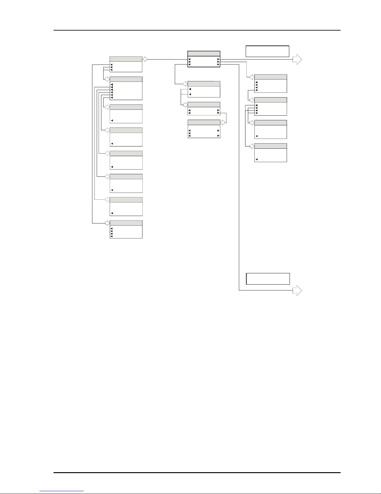
Operation from an Active Control Panel
The card may be operated from an active control panel via the RollCall™ network.
All operational parameters and selections are
made using a system of menus displayed in two
LCD windows.
Operational details for the remote control panel
can be found in the Modular System Operator's
Manual.
Information Window
The Information window has four lines of text
indicating the current state of the unit.
For details of the abbreviations used please see
page 38.
Control Window
The Control window displays all Selection Menus
and sub-menus.
The selection is made by pressing the button
adjacent to the required item.
The menu structure is detailed in the following
pages.
03:IQDMX01
IN: *625 B
Out:625
◀◀◀◀ Video… Audio…▶▶▶▶
◀
◀ ◀
◀ Freeze… Video Delay…▶▶▶▶
◀ User Mem… Setup…▶▶▶▶
Page 41
IQDMX01/03/11/13 B5
IQDMX01OPS 05/04/07 www.snellwilcox.com Version 1 Issue 12 B5.41
Input
Input 1 SDI
Input 2 SDI
525
625
Chroma_B/WProcAmp 1, 2
In 1, 2 ProcAmp Enable
Luma Gain
Chroma Gain
Black Level
Picture Position
Y/C Timing
Input...
ProcAmp 1
ProcAmp 2
Video
IQDMX01 MENU
Video...
Freeze...
User Mem...
Audio...
Video Delay
Setup...
Chroma_B/WUser Mem
Memory 1...
to
Memory 8...
Name Memory 1-8
Name Memory 1-8
Clear
Preset
memory_name
OK
Memory 1 to 8
Save 1-8
Clear 1-8
Recall 1-8
Name 1-8
Preset
Luma Gain
0.0 dB
Luma Gain
Chroma Gain
0.0 dB
Preset
Chroma Gain
Black Level
00.0 mV
Preset
Black Level
Y/C Timing
0ns
Preset
Y/C Timing
Picture Position
0ns
Preset
Picture Position
Video Delay
0 Frame Delay
1 Frame Delay
2 Frame Delay
Delay Phase...
Chroma_B/W
Delay Phase
625 H Phase
625 V Phase
525 H Phase
525 V Phase
625/525 V Phase
20 Lines
Preset
625/525 V Phase
625/525 H Phase
20436ns
Preset
625/525 H Phase
IQDMX01 Menu
System
See Page
42
See Page
43
Page 42

IQDMX01/03/11/13 B5
IQDMX01OPS 05/04/07 www.snellwilcox.com Version 1 Issue 12 B5.42
De-embed
Input 1 SDI
Input 2 SDI
Follow Video
Audio
De-embed...
ProcAmp....
Mix...
Delay...
AES Output…
Embed...
Buses...
Monitor...
Chroma_B/WMonitor
Silence Level
Low Level
High Level
Overload Level
Warning Timer
Warning Timer
14 sec
Preset
Warning Timer
Levels
-32.0 dB
Preset
Levels
Chroma_B/W
AES 1, 2 Source
BUS A
BUS B
BUS C
BUS D
DeEmbed 1
DeEmbed 2
DeEmbed 3
DeEmbed 4
DeEmbed 5
DeEmbed 6
DeEmbed 7
DeEmbed 8
Test Tone
Silence
AES Output
AES 1 Source
AES 2 Source
Delay
Delay Select...
Manual Delay
Delay Status...
Status Items
xxxxxxx
OK
Status Items
Manual Delay
987 ms
Preset
Manual Delay
Manual
Rolltrack 14
Rolltrack 15
Rolltrack 16
Rolltrack 17
GPI Delay Display
Total Delay Display
Delay Status
Manual
Rolltrack 14
Rolltrack 15
Rolltrack 16
Rolltrack 17
GPI Delay Select
Delay Select
Mix
Mixer 1...
Mixer 2...
Mixer 3...
Mixer 4...
Mixer (x) 1, 2, 3, 4
Mix(x) Source1...
Mix(x) Source2...
Mix(x) Source3...
Mix(x) Source4...
Gain1
Gain2
Gain3
Gain4
Mixer (x) Select 1, 2, 3, 4
DeEmbed 1L
DeEmbed 2L
DeEmbed 3L
DeEmbed 4L
DeEmbed 5L
DeEmbed 6L
DeEmbed 7L
DeEmbed 8L
DeEmbed 1R
DeEmbed 2R
DeEmbed 3R
DeEmbed 4R
DeEmbed 5R
DeEmbed 6R
DeEmbed 7R
DeEmbed 8R
Gain 1, 2, 3, 4
-24dB
Preset
Gain 1, 2, 3, 4
Chroma_B/WProcAmp
Stereo 1
De-embed 1L...
De-embed 1R...
Stereo 2
De-embed 2L...
De-embed 2R...
Stereo 3
De-embed 3L...
De-embed 3R...
Stereo 4
De-embed 4L...
De-embed 4R...
Stereo 5
De-embed 5L...
De-embed 5R...
Stereo 6
De-embed 6L...
De-embed 6R...
Stereo 7
De-embed 7L...
De-embed 7R...
Stereo 8
De-embed 8L...
De-embed 8R
Gain De-embed 1-8 L/R
Invert
Mute
De-embed 1-8 L/R
Gain De-embed1-8 L/R
6.0dB
Preset
Gain De-embed 1-8 L/R
Embedder 1, 2, 3, 4
Embed 1, 2, 3, 4 Source...
Pair Selection...
Disable
Embed
Embedder 1...
Embedder 2...
Embedder 3...
Embedder 4...
Select Pair 1
Select Pair 2
Select Pair 3
Select Pair 4
Select Pair 5
Select Pair 6
Select Pair 7
Select Pair 8
Pair Selection
BUS A
BUS B
BUS C
BUS D
Test Tone
Silence
Embed 1, 2, 3, 4 Source
Chroma_B/W
Bus ProcAmp
Stereo A
Bus AL...
Bus AR...
Stereo B
Bus BL...
Bus BR...
Stereo C
Bus CL...
Bus CR...
Stereo D
Bus DL...
Bus DR...
Bus A, B, C, D L/R
Gain Bus
A, B, C, D L/R
Invert
Mute
Bus A, B, C, D L/R
DeEmbed 1L
DeEmbed 2L
DeEmbed 3L
DeEmbed 4L
DeEmbed 5L
DeEmbed 6L
DeEmbed 7L
DeEmbed 8L
MIX 1
MIX 3
DeEmbed 1R
DeEmbed 2R
DeEmbed 3R
DeEmbed 4R
DeEmbed 5R
DeEmbed 6R
DeEmbed 7R
DeEmbed 8R
MIX 2
MIX 4
Gain Bus
6.0dB
Preset
A, B, C, D L/R
Gain Bus
A, B, C, D L/R
BusAL Source...
BusAR Source...
BusBL Source...
BusBR Source...
BusCL Source...
BusCR Source...
BusDL Source...
BusDR Source...
Bus Source
Buses
Bus Source...
Bus ProcAmp...
Page 43

IQDMX01/03/11/13 B5
IQDMX01OPS 05/04/07 www.snellwilcox.com Version 1 Issue 12 B5.43
Chroma_B/W
Logging Status
INPUT=
STD=
INPUT1=
STD1=
INPUT2=
STD2=
EDH=
ERRSEC=
ROLLTRACK=
DEEMBED1=
DEEMBED2=
DEEMBED3=
DEEMBED4=
DEEMBED5=
DEEMBED6=
DEEMBED7=
DEEMBED8=
NPCM1=
NPCM2=
NPCM3=
NPCM4=
NPCM5=
NPCM6=
NPCM7=
NPCM8=
BUS1=
BUS2=
BUS3=
BUS4=
BUS5=
BUS6=
BUS7=
BUS8=
FAULT=
Chroma_B/W
Information Window
Input Status
EDH & ANC Status
Audio Input Status
Reset Errors
Setup
Pattern...
Caption...
Blanking...
Audio Tone...
Slew Rate...
Channel Status
GPI I/O...
RollTrack...
Logging...
Logging Status...
Information Window...
Default Output...
Unit...
Video
Freeze
Pattern
Black
EBU Colour Bars
100% Colour Bars
Ramp
Multiburst
Pulse & Bar
Default Output
Unit
Software Version
Serial No
Preset Unit
Restart
Build No
Serial No
Serial No
xxxxxxx
OK
Build No
Build No
xxxxxxx
OK
Software Version
Software Version
x.x.x
OK
Chroma_B/W
Logging
Input
Std
Input1
Std1
Input2
Std2
EDH
EDH Errors
Rolltrack
De-embed 1
De-embed 2
De-embed 3
De-embed 4
De-embed 5
De-embed 6
De-embed 6
De-embed 7
nPCM 1
nPCM 2
nPCM 3
nPCM 4
nPCM 5
nPCM 6
nPCM 7
nPCM 8
Audio
Non PCM
Bus AL
Bus AR
Bus BL
Bus BR
Bus CL
Bus CR
Bus DL
Bus DR
Fault
Logging Status Items
Logging Status Items
xxxxxxx
OK
RollTrack
RollTrack Index
RollTrack Source
RollTrackDisable
RollTrack Address
RollTrack Command
RollTrack Sending
RollTrack Status
RollTrack Source
Audio Delay
Preset
RollTrack Source
RollTrack Index
10
Preset
RollTrack Index
RollTrack Command
RollTrack Command
0
Clear
Preset
OK
RollTrack Sending/Status
RollTrack Sending/Status
YES
OK
RollTrack Address
RollTrack Address
0
Clear
Preset
OK
GPI Input/Output
GPI/O 1
GPI I/O
GPI Input...
GPI Output...
GPI Input/Output...
GPI Output
Out Active High
Output Selection...
GPI Out Status
GPI Out Status
GPI Out Status
Low
OK
GPI In Status
GPI In Status
Low
OK
GPI Input
Disable Inputs
Input Timer Enable
Timer Active High
Input Selection
GPI In Status
Input Selection
Unused
Preset
InputsSelection
Preset
Input Selection
Output Selection
Input Present
Standard 625
Video Delay
Unused
Chroma_B/WAudio Tone
Ident Enable
Frequency
Frequency R
HeadRoom
Channel Status
Channel Status
Clear
Preset
0
OK
Slew Rate
Instant
Medium
Slowest
Fast
Slow
HeadRoom
18.0 dB
Preset
HeadRoom
Frequency R
10000.0 Hz
Preset
Frequency R
Frequency
8000.0 Hz
Preset
Frequency
VI Pass 525...
VI Pass 625...
Hanc Blank
Blanking
VI Pass 625
Blank All
Line 7
to
Line 23
Pass All
Line 320
to
Line 335
VI Pass 525
Blank All
Line 11
to
Line 21
Pass All
Line 274
to
Line 283
Edit Caption
Edit Caption
Clear
Preset
IQDMX01
OK
Edit Caption
Caption Off
Caption On
Caption
Animated Pattern
Enable Pattern
Black
EBU Colour Bars
100% Colour Bars
Ramp
Multiburst
Pulse & Bar
Pattern
Page 44

IQDMX01/03/11/13 B5
IQDMX01OPS 05/04/07 www.snellwilcox.com Version 1 Issue 12 B5.44
MENU DETAILS
(see IQDMX01 Menu System on previous pages)
MAIN MENU
The main or top level menu allows various submenus to be selected by pressing the button
adjacent to the required text line.
Note that where a menu item is followed by three
dots (...) this indicates that a further sub-menu may
be selected.
Whenever a menu item is selected the parameters
of that selection will be displayed in the Information
window of the front panel. Where the selection is
purely a mode selection and does not enable a
sub-menu, the text will become reversed (whiteon-black) indicating that the mode is active. If the
mode is not available for selection the text will
remain normal.
Also refer to the block diagram on page 6 for more
information.
MAIN MENU
IQDMX01 MENU
Video...
Freeze...
User Mem...
Audio...
Video Delay
Setup...
Video
This item allows the input signal to be selected and
adjustments to be made.
Input...
ProcAmp 1
ProcAmp 1
Video
◀ Input
This item allows the input signal and its standard
to be selected.
Input
Input 1 SDI
Input 2 SDI
525
625
◀ Input 1 SDI, Input 2 SDI
This item allows the input signal to be selected;
either Input 1 SDI, Input 2 SDI or may be selected.
Note that as the IQDMX0315-1A and
IQDMX1315-1A versions have only one input,
Input 1 SDI should always be selected. If Input 2
SDI is selected the unit will report an input loss.
◀ 525, 625
This allows input standard to be selected.
If only 625 is selected the unit will be forced to only
accept 625 line inputs.
If only 525 is selected the unit will be forced to only
accept 525 line inputs.
If 625 and 525 are selected the unit will accept
both 625 and 525 line inputs.
Page 45

IQDMX01/03/11/13 B5
IQDMX01OPS 05/04/07 www.snellwilcox.com Version 1 Issue 12 B5.45
◀ ProcAmp 1, ProcAmp 2
These items allow signal levels and timings for
each of the input channels to be adjusted.
Chroma_B/WProcAmp 1, 2
In 1, 2 ProcAmp Enable
Luma Gain
Chroma Gain
Black Level
Picture Position
Y/C Timing
◀
◀ ◀
◀ In 1, 2, ProcAmp Enable
When selected the ProcAmp will become enabled
for that channel and the settings will be applied to
the signal.
When unselected the settings will revert to the
preset values.
All the values below may be adjusted using the
spinwheel.
◀
◀ ◀
◀ Luma Gain
Preset
Luma Gain
0.0 dB
Luma Gain
This allows the Y (luminance) gain to be adjusted
by ±6 dB in steps of 0.1 dB. Preset value is 0.0 dB.
◀
◀ ◀
◀ Chroma Gain
Chroma Gain
0.0 dB
Preset
Chroma Gain
This allows the Cb/Cr (color difference) gain to be
adjusted by ±6 dB in steps of 0.1 dB. Preset value
is 0.0 dB.
◀
◀ ◀
◀ Black Level
Black Level
00.0 mV
Preset
Black Level
This allows the black level to be adjusted by
+
100mV in 0.8mV steps. Preset value is 0.
◀
◀ ◀
◀ Picture Position
Picture Position
0ns
Preset
Picture Position
This item allows the timing of the picture position
relative to the normal value, to be adjusted.
The timing may be adjusted by +592ns in 148ns
steps.
◀
◀ ◀
◀ Y/C Timing
Y/C Timing
0ns
Preset
Y/C Timing
This item allows the timing of the chrominance
signal relative to the luminance signal to be
adjusted, (i.e. Y to Cb/Cr timing) in nanoseconds.
The timing may be adjusted by +592ns in 148ns
steps.
Freeze
When selected the output picture will become a
frozen frame.
Page 46

IQDMX01/03/11/13 B5
IQDMX01OPS 05/04/07 www.snellwilcox.com Version 1 Issue 12 B5.46
User Mem(ories)
This function allows a number of particular setups
of the IQDMX01 to be saved and recalled. There
are 8 memory locations available.
This item allows any of the 8 memory locations to
be selected.
Chroma_B/WUser Mem
Memory 1...
to
Memory 8...
◀
◀ ◀
◀ Memory 1 to 8
Memory 1 to 8
Save 1-8
Clear 1-8
Recall 1-8
Name 1-8
When a memory location has been selected this
item allows it to be saved, recalled, cleared or
renamed.
◀
◀ ◀
◀ Save 1-8
When selected the current settings will be saved at
this location.
Recall 1-8 ▶▶▶▶
When selected the settings will be recalled from
this location and applied to the unit.
◀
◀ ◀
◀ Clear 1-8
When selected the memory location will be cleared
and returned to the default (preset) setting.
Name 1-8 ▶▶▶▶
The selected memory location may be renamed
with this function.
To compile/edit the text the right ▶ and left ◀
buttons adjacent to the upper text line in the menu
should be used to select the character position in
the text and the spinwheel used to select the
character.
Name Memory 1-8
Name Memory 1-8
Clear
Preset
memory_name
OK
The ◀ Clear function blanks the selected
character.
The ◀ Preset function loads the default text, for
example, Memory 1.
O.K. ▶ saves the memory name text and returns
to the main menu.
Page 47

IQDMX01/03/11/13 B5
IQDMX01OPS 05/04/07 www.snellwilcox.com Version 1 Issue 12 B5.47
Audio
This menu allows the audio processing functions
to be set up.
Audio
De-embed...
ProcAmp....
Mix...
Delay...
AES Output…
Embed...
Buses...
Monitor...
◀
◀ ◀
◀ De-embed
This allows the audio signal to be selected for
processing.
De-embed
Input 1 SDI
Input 2 SDI
Follow Video
◀ Input 1 SDI, Input 2 SDI
This allows audio derived from either Input 1 SDI
or Input 2 SDI to be selected for processing.
◀ Follow Video
When selected the audio will be derived from the
video input signal that has been selected for
processing.
Non-PCM groups can be transparently passed but
if a non-PCM group is selected for mixing or
routing it will be automatically muted.
If a Dolby header is detected in the data stream it
will be processed as a non-PCM signal.
ProcAmp ▶▶▶▶
This allows the control of Gain, Mute, and Polarity
of de-embedded channels.
Chroma_B/WProcAmp
Stereo 1
De-embed 1L...
De-embed 1R...
Stereo 2
De-embed 2L...
De-embed 2R...
Stereo 3
De-embed 3L...
De-embed 3R...
Stereo 4
De-embed 4L...
De-embed 4R...
Stereo 5
De-embed 5L...
De-embed 5R...
Stereo 6
De-embed 6L...
De-embed 6R...
Stereo 7
De-embed 7L...
De-embed 7R...
Stereo 8
De-embed 8L...
De-embed 8R
◀ Stereo (1, 2, 3, 4, 5, 6, 7, 8)
When selected the left and right channels will be
configured as a stereo pair and any adjustments
made to one channel will automatically be applied
to both channels.
◀ De-embed 1-8 L/R
This allows the bus signals to be adjusted and
configured.
Gain De-embed 1-8 L/R
Invert
Mute
De-embed 1-8 L/R
◀ Gain De-embed (1-8) Left/Right
This allows the gain of the selected de-embedded
signal to be adjusted.
The gain may be adjusted over a range of ±18 dB
in 0.1 dB steps. Preset is to 0 dB.
◀ Invert
When selected the signal polarity of the selected
bus signal will be inverted.
◀ Mute
When selected the selected bus signal will be
muted.
Page 48

IQDMX01/03/11/13 B5
IQDMX01OPS 05/04/07 www.snellwilcox.com Version 1 Issue 12 B5.48
Mix ▶▶▶▶
There are four separate audio mixers Mix 1, 2, 3
and 4. The outputs of these mixers provide four
extra input selections for the Channel Router.
This menu allows each of the mixers to be
selected and configured.
Mix
Mixer 1...
Mixer 2...
Mixer 3...
Mixer 4...
◀ Mixer 1, 2, 3 and 4
Each mixer has four inputs and this item allows the
mixer input to be selected and the gain of that
channel adjusted.
Mixer (x) 1, 2, 3, 4
Mix(x) Source ...
Mix(x) 2...
Mix(x) Source3...
Mix(x) Source4...
1
Source
Gain1
Gain2
Gain3
Gain4
◀ Mixer 1, 2, 3 and 4 Source 1-4 (inputs)
This allows the signal source for the selected input
of the selected mixer, to be chosen.
Mixer (x) Select 1, 2, 3, 4
DeEmbed 1L
DeEmbed 2L
DeEmbed 3L
DeEmbed 4L
DeEmbed 5L
DeEmbed 6L
DeEmbed 7L
DeEmbed 8L
DeEmbed 1R
DeEmbed 2R
DeEmbed 3R
DeEmbed 4R
DeEmbed 5R
DeEmbed 6R
DeEmbed 7R
DeEmbed 8R
Gain 1-4 ▶▶▶▶
These are the individual gain controls that allow
the mixing levels for each of the input signals, to
be adjusted.
Gain 1, 2, 3, 4
-24dB
Preset
Gain 1, 2, 3, 4
The range of adjustment is from 0 to –90 dB and to
Off.
0 to -60 dB is in steps of 1 dB; -60 dB to -90 dB is
in steps of 3 dB.
Delay ▶▶▶▶
This menu allows the amount of delay to be set
and type of audio delay mechanism to be selected.
Delay
Delay Select...
Manual Delay
Delay Status...
◀ Delay Select
This allows the type of audio delay mechanism to
be selected. One or more of the types may be
checked. The amount of delay applied will be the
sum of the delay from the enabled delay
mechanisms.
Manual
Rolltrack 14
Rolltrack 15
Rolltrack 16
Rolltrack 17
GPI Delay Select
Delay Select
Note that up to 0.5 s of delay may be applied from
the sum of the GPI + RollTrack delay inputs.
◀ Manual
When selected an audio delay set by the Manual
Delay control will be applied, immediately.
Manual Delay
987 ms
Preset
Manual Delay
◀ RollTrack 14, 15, 16 and 17
The selected source(s) of the RollTrack input
signal(s) will apply an audio delay, smoothly
compensating.
Also see page 60.
Page 49

IQDMX01/03/11/13 B5
IQDMX01OPS 05/04/07 www.snellwilcox.com Version 1 Issue 12 B5.49
◀ GPI Delay Select
When selected an audio delay will be applied that
is equal to the width of the pulse arriving at the
GPI connector.
Note that an audio delay pulse of more than
500 ms, applied to the GPI Input will be treated as
invalid. This will result in the GPI delay returning to
zero.
Note that the GPI must be configured correctly for
this function to operate. Please see page 58 for
details.
◀ Delay Status
The status (and amount) of delay produced by
each of the delay methods may be chosen from
this menu.
Manual
Rolltrack 14
Rolltrack 15
Rolltrack 16
Rolltrack 17
GPI Delay Display
Total Delay Display
Delay Status
◀ Status Items
The status (and amount) of delay of the chosen
item will be displayed in this window.
Status Items
xxxxxxx
OK
Status Items
AES Output ▶▶▶▶
This allows the AES signal source for the AES
output to be selected.
AES Output
AES 1 Source
AES 2 Source
◀ AES 1 and 2 Source
This allows the signal from the AES source to be
selected. Silence and audio test tones may also be
selected.
Chroma_B/WAES 1, 2 Source
BUS A
BUS B
BUS C
BUS D
DeEmbed 1
DeEmbed 2
DeEmbed 3
DeEmbed 4
DeEmbed 5
DeEmbed 6
DeEmbed 7
DeEmbed 8
Test Tone
Silence
Page 50

IQDMX01/03/11/13 B5
IQDMX01OPS 05/04/07 www.snellwilcox.com Version 1 Issue 12 B5.50
◀
◀ ◀
◀ Embed
There are four embedders. This function sets up
the embedder sources and destinations to be
selected for each of these embedders.
Embed
Embedder 1...
Embedder 2...
Embedder 3...
Embedder 4...
This allows each of the embedders to be selected.
◀ Embedder 1, 2, 3 and 4
This allows the embedder functions to be selected.
Embedder 1, 2, 3, 4
Embed 1, 2, 3, 4 Source...
Pair Selection...
Disable
◀ Embed 1, 2, 3, and 4 Source
This allows the source for the embedder to be
selected.
BUS A
BUS B
BUS C
BUS D
Test Tone
Silence
Embed 1, 2, 3, 4 Source
◀ BUS A, B, C and D
The source may be derived from one of the three
busses.
◀ Test Tone
The source will be a test tone derived from the
Setup/Audio Tone menu.
◀ Silence
The source will be silence.
For details of the Audio Embedding Packet
Distribution please refer to Appendix 2 on page 80.
◀ Pair Selection
The destination for the embedded signal may be
selected from the list.
Select Pair 1
Select Pair 2
Select Pair 3
Select Pair 4
Select Pair 5
Select Pair 6
Select Pair 7
Select Pair 8
Pair Selection
◀ Disable
When selected the embedder will be turned off,
(for this embedder).
Page 51

IQDMX01/03/11/13 B5
IQDMX01OPS 05/04/07 www.snellwilcox.com Version 1 Issue 12 B5.51
◀
◀ ◀
◀ Buses
This function allows the inputs for the four audio
buses of the router to be selected and adjusted.
Buses
Bus Source...
Bus ProcAmp...
For each bus any source may be for the left and
right channels.
◀ Bus Source
This allows the bus source to be selected.
BusAL Source...
BusAR Source...
BusBL Source...
BusBR Source...
BusCL Source...
BusCR Source...
BusDL Source...
BusDR Source...
Bus Source
◀ Bus (A-D) L/R Source
This allows the audio source for the left and right
channels of the bus to be selected.
Bus A, B, C, D L/R
DeEmbed 1L
DeEmbed 2L
DeEmbed 3L
DeEmbed 4L
DeEmbed 5L
DeEmbed 6L
DeEmbed 7L
DeEmbed 8L
MIX 1
MIX 3
DeEmbed 1R
DeEmbed 2R
DeEmbed 3R
DeEmbed 4R
DeEmbed 5R
DeEmbed 6R
DeEmbed 7R
DeEmbed 8R
MIX 2
MIX 4
◀ DeEmbed (1-8) L/R
The audio source for the left and right channels of
the bus may be selected from the De-Embedded
signals or the output of one four mixers.
◀
◀ ◀
◀ Bus ProcAmp
This allows the bus signals to be configured and
adjusted.
Chroma_B/WBus ProcAmp
Stereo A
Bus AL...
Bus AR...
Stereo B
Bus BL...
Bus BR...
Stereo C
Bus CL...
Bus CR...
Stereo D
Bus DL...
Bus DR...
◀ Stereo (A, B, C, D)
When selected the left and right channels will be
configured as a stereo pair and any adjustments
made to one channel will automatically be applied
to both channels.
◀ Bus (A, B, C, D) Left/Right
Bus A, B, C, D L/R
Gain Bus
A, B, C, D L/R
Invert
Mute
This allows the bus signals to be adjusted and
configured.
◀ Gain Bus (A, B, C, D) Left/Right
This allows the gain of the selected bus signal
channel to be adjusted.
Gain Bus
6.0dB
Preset
A, B, C, D L/R
Gain Bus
A, B, C, D L/R
The gain may be adjusted over a range of ±18 dB
in 0.1 dB steps. Preset is to 0 dB.
◀ Invert
When selected the signal polarity of the selected
bus signal will be inverted.
◀ Mute
When selected the selected bus signal will be
muted.
Page 52

IQDMX01/03/11/13 B5
IQDMX01OPS 05/04/07 www.snellwilcox.com Version 1 Issue 12 B5.52
◀
◀ ◀
◀ Monitor
The four audio buses are monitored and level
detectors provide status information and logging
data.
Chroma_B/WMonitor
Silence Level
Low Level
High Level
Overload Level
Warning Timer
Levels
Levels
-32.0 dB
Preset
Levels
These levels may be adjusted by rotating the
spinwheel.
◀ Silence Level
The level at which the signal is considered to have
dropped to silence may be set with this control.
The range is from -80 dB to 0 dB in steps of 1 dB.
Preset is to -70 dB.
◀ Low Level
The level at which the signal is considered to have
dropped to a Low Level may be set with this
control.
The range is from -80 dB to 0 dB in steps of 1 dB.
Preset is to -60 dB.
◀ High Level
The level at which the signal is considered to have
risen to a High Level may be set with this control.
The range is from -80 dB to 0 dB in steps of 1 dB.
Preset is to -10 dB.
◀ Overload
The level at which the signal is considered to have
risen to an Overload condition may be set with this
control.
The range is from -80 dB to 0 dB in steps of 1 dB.
Preset is to 0 dB.
◀
◀ ◀
◀ Warning Timer
All the above monitoring facilities will only operate
after a time interval set by this control. When OK it
will operate immediately.
Warning Timer
14 sec
Preset
Warning Timer
The range is from 1 to 20 seconds. Preset is to 10
seconds.
Page 53
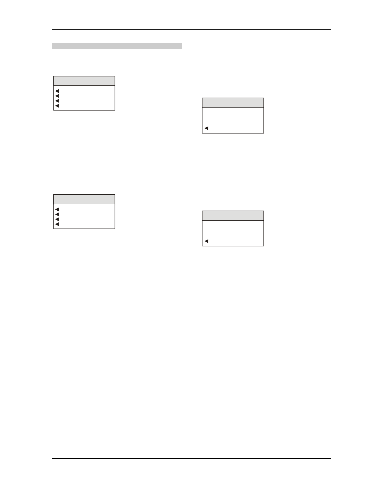
IQDMX01/03/11/13 B5
IQDMX01OPS 05/04/07 www.snellwilcox.com Version 1 Issue 12 B5.53
Video Delay
This allows the output signal to be delayed relative
to the input signal.
Video Delay
0 Frame Delay
1 Frame Delay
2 Frame Delay
Delay Phase...
◀
◀ ◀
◀ 0, 1, 2 Frame Delay
The number of frames that the output signal will
appear after the input signal may be set with these
items.
◀
◀ ◀
◀ Delay Phase
When these controls are used the output signal will
appear after the input signal with a time delay.
Chroma_B/WDelay Phase
625 H Phase
625 V Phase
525 H Phase
525 V Phase
◀
◀ ◀
◀ 625/525 H(Horizontal) Phase
This item allows the horizontal timing of the output
signal relative to the input signal to be adjusted by
up to 1 line in 37 ns steps. The spinwheel will
adjust this value.
625/525 H Phase
20436ns
Preset
625/525 H Phase
Selecting Preset returns the setting to the
minimum horizontal delay.
◀
◀ ◀
◀ 625/525 V(Vertical) Phase
This item allows the vertical timing of the output
signal relative to the input signal to be adjusted, in
TV lines. The spinwheel will adjust this value.
Range is from 0 to 624 or 524 lines in 1 line steps.
625/525 V Phase
20 Lines
Preset
625/525 V Phase
Selecting Preset returns the setting to the
minimum vertical delay.
Page 54

IQDMX01/03/11/13 B5
IQDMX01OPS 05/04/07 www.snellwilcox.com Version 1 Issue 12 B5.54
Setup…
◀
◀ ◀
◀ Pattern
This function will allow various patterns to be used
as the output signal.
Animated Pattern
Enable Pattern
Black
EBU Colour Bars
100% Colour Bars
Ramp
Multiburst
Pulse & Bar
Pattern
◀ Animated Pattern
When selected, a monochrome rectangular area
will appear on the output picture as shown
opposite. The brightness of this rectangle will ramp
from black, through gray to white and then directly
to black over a period of about one second. This
action will then be repeated continuously.
This pattern is useful for checking active video
paths. Down stream equipment can see that video
has not been frozen.
◀ Enable Pattern
When selected the output will become the pattern
highlighted in the Pattern list.
Animated Pattern
Wh
ite
Black
Animated Pattern Brightness
~1 Second
Page 55

IQDMX01/03/11/13 B5
IQDMX01OPS 05/04/07 www.snellwilcox.com Version 1 Issue 12 B5.55
◀
◀ ◀
◀ Caption
This function allows control of the caption which
may contain a maximum of 19 characters (white
text on a black background).
The caption will appear in the lower section of the
picture.
Edit Caption
Caption Off
Caption On
Caption
◀ Edit Caption
This allows a caption to be edited.
Edit Caption
Edit Caption
Clear
Preset
IQMUX01
OK
To compile/edit the text the right ▶ and left ◀
buttons adjacent to the upper text line in the menu
should be used to select the character position in
the text and the spinwheel used to select the
character.
The ◀ Clear function blanks the selected
character.
The ◀ Preset function loads the default text, for
example, IQMUX01.
O.K. ▶ saves the memory name text and returns
to the main menu.
◀ Caption Off
When selected the caption will be turned off.
◀ Caption On
When selected the caption will be turned on.
Caption Text
This is the caption
Page 56

IQDMX01/03/11/13 B5
IQDMX01OPS 05/04/07 www.snellwilcox.com Version 1 Issue 12 B5.56
◀
◀ ◀
◀ Blanking
This item allows the Vertical Interval data (all or
specific lines) contained in the input signal to be
blanked or passed through the module.
VI Pass 525...
VI Pass 625...
Hanc Blank
V Flag (OBD)
Blanking
◀ VI Pass 525
This item allows lines 11 to 21 and lines 274 to
283 of 525 line signals to be selected and either
passed (highlighted) to the output or blanked from
the output.
VI Pass 525
Blank All
Line 11
to
Line 21
Pass All
Line 274
to
Line 283
◀ Blank All
Selecting this item will select all vertical interval lines in
the 525 line list and blank them from the output.
Pass All ▶▶▶▶
Selecting this item will select all vertical interval
lines in the 525 line list and allow them to passed
through to the output.
VI Pass 625
Blank All
Line 7
to
Line 23
Pass All
Line 320
to
Line 335
◀ VI Pass 625
This section allows lines 7 to 23 and lines 320 to 335
of 625 line signals to be selected and either passed
(highlighted) to the output or blanked from the output.
◀ Blank All
Selecting this item will select all vertical interval lines in
the 625 line list and blank them from the output.
Pass All ▶▶▶▶
Selecting this item will select all vertical interval
lines in the 625 line list and allow them to passed
through to the output.
◀ Hanc Blank
When checked all horizontal data will be blanked,
on the input. When unselected, passthrough
operations will not alter audio packets for groups
that the IQDMX01 has not selected for embedding.
In order to allow minimum synchronization delay
the created packets are output first and then the
passthrough groups are placed after the created
streams have been embedded. This means that
passthrough is achieved without altering the input
packet distribution. Passthrough operation has to
take note of marked for deletion packets and these
are removed where possible to ensure that one
does not run out of useable ancillary space.
For details of the HANC Data Handling please
refer to Appendix 2 on page 80.
◀ V Flag (OBD)
This control allows the V(ertical) Flag to be
changed from line 10 (OVD, Optional Video Data)
to line 20 (OBD, Optional Blanking Data).
Un-highlighted selects OVD and highlighted
selects OBD. The default is OVD selected.
Note that this function is only active for 525 line
signals.
Page 57

IQDMX01/03/11/13 B5
IQDMX01OPS 05/04/07 www.snellwilcox.com Version 1 Issue 12 B5.57
◀
◀ ◀
◀ Audio Tone
The frequency of the Audio Test Tone may be set
using this control. Left and right channels may be
set to different frequencies.
Chroma_B/WAudio Tone
Ident Enable
Frequency
Frequency R
HeadRoom
◀ Ident Enable
When selected the right channel will be identified by the
signal being muted for 0.5 second every 2.5 seconds.
◀ Frequency
This adjusts the frequency of the test tone for the
left channel only.
Frequency
8000.0 Hz
Preset
Frequency
The range is from 100 Hz to 15 kHz in steps of
100 Hz. Preset is to 400 Hz.
◀ Frequency R
This adjusts the frequency of the test tone for the
right channel only.
Frequency R
10000.0 Hz
Preset
Frequency R
The range is from 100 Hz to 15 kHz in steps of
100 Hz. Preset is to 400 Hz.
◀ Headroom
This allows the headroom to be set.
HeadRoom
18.0 dB
Preset
HeadRoom
The range is from 4 dB to 24dB in 1 dB steps.
Preset is to 18 dB.
Note that in this product headroom is defined as:
Clipping Leve
l
(0 dBFS)
Peak Level
(Operational)
Line-up Level
(0dBu)
Headroom
Headroom = Clipping Level – Line-up level
◀
◀ ◀
◀ Slew Rate
This is the time taken for the audio to slew when
the audio mixing and routing controls have
changed.
Slew Rate
Instant
Medium
Slowest
Fast
Slow
The options are:
Instant ... The response is immediate
Slowest . Change takes approximately one second
Slow ...... Change takes 75% of Slowest time
Medium . Change takes 50% of Slowest time
Fast Change takes 25% of Slowest time
◀
◀ ◀
◀ Channel Status
Channel Status
Channel Status
Clear
Preset
0
OK
This will set the four character name used in the
destination field of the audio channel status.
Note that the Channel Status Origin data is
automatically set by the module to DMX1 and
cannot be changed.
Page 58

IQDMX01/03/11/13 B5
IQDMX01OPS 05/04/07 www.snellwilcox.com Version 1 Issue 12 B5.58
◀
◀ ◀
◀ GPI/O
This function allows the GPI functions to be
configured and their actions defined.
GPI I/O
GPI Input...
GPI Output...
GPI Input/Output...
◀ GPI Input
This item allows the GPI input functions to be
configured.
GPI Input
Disable Inputs
Input Timer Enable
Timer Active High
Input Selection
GPI In Status
◀ Disable Inputs
When selected all GPI input functions will be
disabled.
◀ Timer Enable
When checked the GPI will be monitored.
The width of the pulse represents the delay that
can be used to control audio delays in this unit.
Note that an audio delay pulse of more than
500 ms, applied to the GPI Input will be treated as
invalid. This will result in the GPI delay returning to
zero.
◀ Timer Active High
When checked the GPI will measure the positive
going pulse.
When unchecked the negative pulse is measured.
◀ Out Active High
Determines the sense of the asserted GPI output
signal.
When checked GPI is active the output sense is
high. When unchecked the GPI is active low.
◀ Input Selection
When configured as an input the GPI connection
may be used for accepting GPI information (from
mechanical switch contacts, relay contacts etc.)
The resulting action that the unit takes may be
selected using this item.
Input Selection
Unused
Preset
InputsSelection
Preset
Input Selection
The GPI input functions that may be selected are
as follows:
Unused The unit will perform no function. This
is also the Preset Setting.
Pattern The unit will produce a pattern chosen
from the Pattern menu when the input
changes from open to closed.
Memory The unit will use the settings in
1 to 8 the selected memory location when
the input changes from open to
closed.
Mem1-2 The unit will toggle between the
settings of memory locations 1 and 2.
Open to Closed = Memory 1 settings
Closed to Open = Memory 2 settings
Mem 3-4 The unit will toggle between the
settings of memory locations 3 and 4.
Open to Closed = Memory 3 settings
Closed to Open = Memory 4 settings
Mem 5-6 The unit will toggle between the
settings of memory locations 5 and 6.
Open to Closed = Memory 5 settings
Closed to Open = Memory 6 settings
Mem 7-8 The unit will toggle between the
settings of memory locations 7 and 8.
Open to Closed = Memory 7 settings
Closed to Open = Memory 8 settings
◀ GPI In Status
This will display the current status of the selected
GPI input.
GPI In Status
GPI In Status
Low
OK
This may show either High or Low. When low, the
associated function will be triggered.
On a transition, the associated function will be
triggered.
Page 59

IQDMX01/03/11/13 B5
IQDMX01OPS 05/04/07 www.snellwilcox.com Version 1 Issue 12 B5.59
◀ GPI Output
This item allows the GPI output functions to be
configured.
GPI Output
Out Active High
Output Selection...
GPI Out Status
◀ Out Active High
This determines the sense of the asserted GPI
output signal.
When selected the GPI is active the output sense
is high. When unchecked the GPI is active low.
◀ Output Selection
The GPO may be configured to produce an output
corresponding to one of the conditions highlighted
in the list.
Output Selection
Input Present
Standard 625
Video Delay
Unused
The preset setting for the output is Unused.
When the condition is not true the output will float
but when the condition is true the output is closed
to ground via a transistor.
Note that when video delay mode is selected the
output is a negative going TTL pulse. The width of
the pulse is 1 millisecond.
◀ GPI Out Status
This will display the current status of the GPI
output.
GPI Out Status
GPI Out Status
Low
OK
This may show either Unused, High, low or video
delay in milliseconds.
◀ GPI I Input/Output
This allows the GPI port to be configured as an
input or an output.
GPI Input/Output
GPI/O 1
When selected the GPI is configured as an output.
When unselected the GPI is configured as an
input.
Page 60
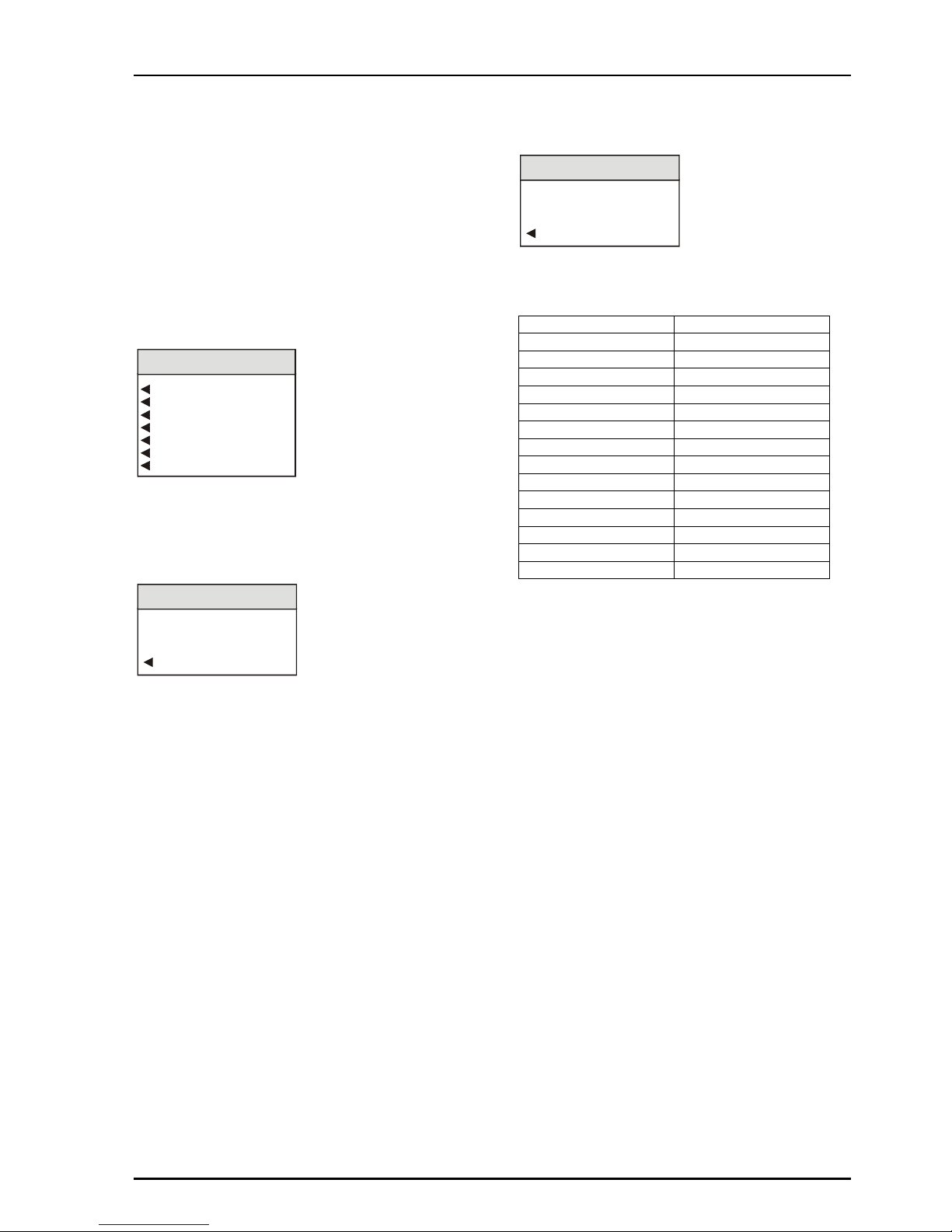
IQDMX01/03/11/13 B5
IQDMX01OPS 05/04/07 www.snellwilcox.com Version 1 Issue 12 B5.60
◀
◀ ◀
◀ RollTrack
This function allows information to be sent, via the
RollCall™ network, to other compatible units
connected on the same network.
For example, it can enable compatible audio delay
units to produce an audio delay dependent on this
and other similar units. The audio delay unit will
dynamically follow or track the received delay-time
information. This allows processed video signals to
be timed correctly with audio signals. This
automatic tracking system via the RollCall™
network is call RollTrack.
RollTrack
RollTrack Index
RollTrack Source
RollTrack Disable
RollTrack Address
RollTrack Command
RollTrack Sending
RollTrack Status
For more detailed information, see the RollTrack
section (Appendix) at the end of this manual.
◀ RollTrack Index
RollTrack Index
10
Preset
RollTrack Index
This item is used to select which RollTrack Index is
set up using the RollTrack Source, RollTrack
Address and RollTrack Command functions.
It allows up to 70 destinations to be selected.
◀ RollTrack Source
RollTrack Source
Audio Delay
Preset
RollTrack Source
This allows the source of information that triggers the
transmission of data to be selected. Options are:
Unused (off) De-embed 1 Lost
Input Present De-embed 1 PCM
Input Missing De-embed 1 NPCM
Standard 525 to
Standard 625 De-embed 8 Lost
Input 1 Present De-embed 8 PCM
Input 1 Missing De-embed 8 NPCM
Standard 1 525 GPI 1 Low
Standard 1 625 GPI 1 High
Input 2 Present GPI 1 Inactive
Input 2 Missing
Standard 2 525
Standard 2 625
Audio Delay
Video Delay
Note that the GPI RollTrack functions should not
be used when GPI Timer Enable is selected.
The destination for the information is set by the
network code address.
◀
◀ ◀
◀ RollTrack Disable
When this item is selected all RollTrack items will
be disabled.
Page 61

IQDMX01/03/11/13 B5
IQDMX01OPS 05/04/07 www.snellwilcox.com Version 1 Issue 12 B5.61
◀ RollTrack Address
This item allows the address of the selected
destination unit to be set.
RollTrack Address
RollTrack Address
0
Clear
Preset
OK
To compile/edit the text the right ▶ and left ◀
buttons adjacent to the upper text line in the menu
should be used to select the character position in
the text and the spinwheel used to select the
character.
The ◀ Clear function blanks the selected
character.
The ◀ Preset function loads the default address.
O.K. ▶ saves the address and returns to the main
menu.
The full RollTrack address has four sets of
numbers
For example: 0000:10:01*99
The first set (0000) is the network segment code
number
The second set (10) is the number identifying the
(enclosure/mainframe) unit.
The third set (01) is the slot number in the unit
The Fourth Set (362)
Each RollCall unit has a unique identification
embedded in the units’ software. In this example
362 represents an IQDMX00, 412 would represent
an IQDEC00, 161 a Mach 1 etc. Inserting this
number in the RollTrack address ensures that only
the correct type of unit (in this example an
IQDMX00) will respond to the RollTrack command;
any other unit will ignore the command.
If this number were set to 00 any type of unit at
this location would respond to the RollTrack
command, possibly causing unpredictable results.
The unit ID of a module on the RollCall network
may be found under RollCall Control
Panel/RollCall Listing/Unit Information or via the
RollCall Control Panel Help/About Current Unit
function.
◀ RollTrack Command
RollTrack Command
RollTrack Command
0
Clear
Preset
OK
The full RollTrack command has two sets of
numbers
For example: 84*156
The first set (84) is the RollTrack command
number
Note that only command numbers 14, 15, 16 and
17 should be used for audio delay
The second set (156) is the value sent with the
RollTrack command number.
For details of the RollCall command values for
specific units please contact your local Snell &
Wilcox agent.
◀ RollTrack Sending
This item shows when the unit is actively sending
the RollTrack command.
RollTrack Sending/Status
RollTrack Sending/Status
YES
OK
This may show:
String A string value is always being sent.
Number A number value is always being sent.
No The message is not being sent.
Yes The message is being sent.
Internal Inconsistent behavior; please contact
Type Error your local Snell & Wilcox agent.
Page 62

IQDMX01/03/11/13 B5
IQDMX01OPS 05/04/07 www.snellwilcox.com Version 1 Issue 12 B5.62
◀ RollTrack Status
This item will show the status of the currently
selected RollTrack index.
This may show:
OK RollTrack message sent and received
OK.
Unknown Rolltrack message has been sent but
it has not yet completed.
Timeout RollTrack message sent but
acknowledgement not received. This
could be because the destination unit
is not at the location specified.
Error This indicates a broken RollCall state.
Bad This indicates a broken RollCall
packet.
Page 63

IQDMX01/03/11/13 B5
IQDMX01OPS 05/04/07 www.snellwilcox.com Version 1 Issue 12 B5.63
◀◀◀◀ Logging
Information about up to various parameters can be
made available to a logging device that is attached
to the RollCall™ network by selecting the
appropriate item.
Chroma_B/WLogging
Input
Std
Input1
Std1
Input2
Std2
EDH
EDH Errors
Rolltrack
De-embed 1
De-embed 2
De-embed 3
De-embed 4
De-embed 5
De-embed 6
De-embed 6
De-embed 7
nPCM 1
nPCM 2
nPCM 3
nPCM 4
nPCM 5
nPCM 6
nPCM 7
nPCM 8
Audio
Non PCM
Bus AL
Bus AR
Bus BL
Bus BR
Bus CL
Bus CR
Bus DL
Bus DR
Fault
Any of the items may be selected from the list.
◀◀◀◀ Logging Status
Chroma_B/WLogging Status
INPUT=
STD=
INPUT1=
STD1=
INPUT2=
STD2=
EDH=
ERRSEC=
ROLLTRACK=
DEEMBED1=
DEEMBED2=
DEEMBED3=
DEEMBED4=
DEEMBED5=
DEEMBED6=
DEEMBED7=
DEEMBED8=
NPCM1=
NPCM2=
NPCM3=
NPCM4=
NPCM5=
NPCM6=
NPCM7=
NPCM8=
BUS1=
BUS2=
BUS3=
BUS4=
BUS5=
BUS6=
BUS7=
BUS8=
FAULT=
This will show the status of the selected item.
Logging Status Items
Logging Status Items
xxxxxxx
OK
Page 64

IQDMX01/03/11/13 B5
IQDMX01OPS 05/04/07 www.snellwilcox.com Version 1 Issue 12 B5.64
ROLLCALL LOG FIELDS
*Note that these log values are either for future use or may be logged during a transitional state whilst
acquiring or loosing an input signal. It is very unlikely that these states and the associated log values will
become permanent.
Log Field Log Value Description
INPUT=
OK
ERR*
LOST
Valid input signal
Invalid input signal
Input signal lost
STD= UNKNOWN*
STDERR
525
625
Input signal standard not recognized or no signal
Not a selected input standard
Input standard 525
Input standard 625
INPUT1=
OK
ERR*
LOST
Valid input signal
Invalid input signal
Input signal lost
STD1=
ERR
525
625
Not a selected input standard
Input standard 525
Input standard 625
INPUT2=
OK
ERR*
LOST
Valid input signal
Invalid input signal
Input signal lost
STD2=
ERR
525
625
Not a selected input standard
Input standard 525
Input standard 625
EDH= NONE
FAIL
OK
RESET
The unit is not locked to the input signal
EDH errors have been found on the input signal
No EDH errors found on the input signal
EDH statistics have been reset
ERRSEC= Runtime string The time since EDH was reset in seconds
ROL_STATES= OK
FAIL
RollTrack message sent and received OK
RollTrack message not acknowledged
DEEMBED_1= NONE
OK
Nothing present on pair 1
Embedded pair 1 present on selected SDI input
DEEMBED_2= NONE
OK
Nothing present on pair 2
Embedded pair 2 present on selected SDI input
DEEMBED_3= NONE
OK
Nothing present on pair 3
Embedded pair 3 present on selected SDI input
DEEMBED_4= NONE
OK
Nothing present on pair 4
Embedded pair 4 present on selected SDI input
DEEMBED_5= NONE
OK
Nothing present on pair 5
Embedded pair 5 present on selected SDI input
DEEMBED_6= NONE
OK
Nothing present on pair 6
Embedded pair 6 present on selected SDI input
DEEMBED_7= NONE
OK
Nothing present on pair 7
Embedded pair 7 present on selected SDI input
DEEMBED_8= NONE
OK
Nothing present on pair 8
Embedded pair 8 present on selected SDI input
NPCM_1= NONE
OK
Non-PCM not present on pair 1 of selected SDI input
Non-PCM present on pair 1 of selected SDI input
NPCM_2= NONE
OK
Non-PCM not present on pair 2 of selected SDI input
Non-PCM present on pair 2 of selected SDI input
NPCM_3= NONE Non-PCM not present on pair 3 of selected SDI input
Page 65

IQDMX01/03/11/13 B5
IQDMX01OPS 05/04/07 www.snellwilcox.com Version 1 Issue 12 B5.65
Log Field Log Value Description
OK Non-PCM present on pair 3 of selected SDI input
NPCM_4= NONE
OK
Non-PCM not present on pair 4 of selected SDI input
Non-PCM present on pair 4 of selected SDI input
NPCM_5= NONE
OK
Non-PCM not present on pair 5 of selected SDI input
Non-PCM present on pair 5 of selected SDI input
NPCM_6= NONE
OK
Non-PCM not present on pair 6 of selected SDI input
Non-PCM present on pair 6 of selected SDI input
NPCM_7= NONE
OK
Non-PCM not present on pair 7 of selected SDI input
Non-PCM present on pair 7 of selected SDI input
NPCM_8= NONE
OK
Non-PCM not present on pair 8 of selected SDI input
Non-PCM present on pair 8 of selected SDI input
BUS_AL= OK
WARNING
Router BUS A Left channel has valid signal selected
Router BUS A Left channel is receiving silence, low level, high
level or overload signal
BUS_AR= OK
WARNING
Router BUS A Right channel has valid signal selected
Router BUS A Right channel is receiving silence, low level,
high level or overload signal
BUS_BL= OK
WARNING
Router BUS B Left channel has valid signal selected
Router BUS B Left channel is receiving silence, low level, high
level or overload signal
BUS_BR= OK
WARNING
Router BUS B Right channel has valid signal selected
Router BUS B Right channel is receiving silence, low level,
high level or overload signal
BUS_CL= OK
WARNING
Router BUS C Left channel has valid signal selected
Router BUS C Left channel is receiving silence, low level, high
level or overload signal
BUS_CR= OK
WARNING
Router BUS C Right channel has valid signal selected
Router BUS C Right channel is receiving silence, low level,
high level or overload signal
BUS_DL= OK
WARNING
Router BUS D Left channel has valid signal selected
Router BUS D Left channel is receiving silence, low level, high
level or overload signal
BUS_DR= OK
WARNING
Router BUS D Right channel has valid signal selected
Router BUS D Right channel is receiving silence, low level,
high level or overload signal
FAULT= NONE
FAIL
No Internal errors detected
Internal error detected
SN= Runtime string Serial number of unit
Page 66

IQDMX01/03/11/13 B5
IQDMX01OPS 05/04/07 www.snellwilcox.com Version 1 Issue 12 B5.66
◀◀◀◀ Information Window
Chroma_B/WInformation Window
Input Status
EDH & ANC Status
Audio Input Status
Reset Errors
The type if information that appears in the
Information Window may be chosen with this item.
◀◀◀◀ Reset Errors
Selecting this function will reset the EDH error
count and the timer shown in the information
window, to zero.
◀◀◀◀ Default Output
If the input signal fails or is of poor quality this
function will determine what the output signal will
become under such conditions.
Video
Freeze
Pattern
Black
EBU Colour Bars
100% Colour Bars
Ramp
Multiburst
Pulse & Bar
Default Output
◀◀◀◀ Pattern
If Pattern is chosen in the Default Output menu
the output will become the pattern chosen from the
list.
◀◀◀◀ Unit
This provides various items of information about
the unit.
Unit
Software Version
Serial No
Preset Unit
Restart
Build No
◀ Software Version
This item reveals a display showing the version of
the software fitted in the module.
Software Version
Software Version
x.x.x
OK
Select OK to return to the Unit Menu.
◀
◀ ◀
◀ Serial No
This item reveals a display showing the serial
number of the module.
Serial No
Serial No
xxxxxxx
OK
Select OK to return to the Unit Menu.
◀ Preset Unit
Selecting this item sets all adjustment functions
that include a preset facility, to their preset values.
Note that this is a momentary action.
◀ Restart
This will reboot the unit simulating a power-down
power-up cycle restoring power-up settings.
◀ Build No
This will indicate the factory build number. This
number defines all parameters of the unit (software
versions, build level etc.) for identification
purposes.
Build No
Build No
xxxxxxx
OK
Select OK to return to the Unit Menu.
Page 67

IQDMX01/03/11/13 B5
IQDMX01OPS 05/04/07 www.snellwilcox.com Version 1 Issue 12 B5.67
IQDMX01 RollCall Commands
Supervisor Level
Command No.
Hex Dec Command Name Values
0001 1 Serial No Static Display (no control)
0002 2 Software Version Static Display (no control)
0003 3 <RETURN> 1=Preset Unit
0004 4 <RETURN> 1=Restart
0005 5 Build No Static Display (no control)
000E 14 Rolltrack 14 Static Display (no control)
000F 15 Rolltrack 15 Static Display (no control)
0010 16 Rolltrack 16 Static Display (no control)
0011 17 Rolltrack 17 Static Display (no control)
040B 1035 Enable Pattern clear=0 set=1 (toggle=2)
040C 1036 <RETURN> 0=Black 1=EBU Colour Bars 2=100%
Colour Bars
3=Ramp 4=Multiburst 5=Pulse & Bar
040D 1037 <RETURN> 0=Caption Off 1=Caption On
040E 1038 <RETURN> 0=Black 1=EBU Colour Bars 2=100%
Colour Bars 3=Ramp
4=Multiburst 5=Pulse & Bar
0411 1041 Edit Caption Edit String
0424 1060 Input clear=0 set=1 (toggle=2)
0425 1061 Std clear=0 set=1 (toggle=2)
0428 1064 EDH clear=0 set=1 (toggle=2)
042D 1069 Fault clear=0 set=1 (toggle=2)
042E 1070 EDH Errors clear=0 set=1 (toggle=2)
0446 1094 Input1 clear=0 set=1 (toggle=2)
0447 1095 Input2 clear=0 set=1 (toggle=2)
0449 1097 Std1 clear=0 set=1 (toggle=2)
044A 1098 Std2 clear=0 set=1 (toggle=2)
0452 1106 RollTrack clear=0 set=1 (toggle=2)
0458 1112 Bus AL clear=0 set=1 (toggle=2)
0459 1113 Bus AR clear=0 set=1 (toggle=2)
045A 1114 Bus BL clear=0 set=1 (toggle=2)
045B 1115 Bus BR clear=0 set=1 (toggle=2)
045C 1116 Bus CL clear=0 set=1 (toggle=2)
045D 1117 Bus CR clear=0 set=1 (toggle=2)
045E 1118 Bus DL clear=0 set=1 (toggle=2)
045F 1119 Bus DR clear=0 set=1 (toggle=2)
0460 1120 De-embed 1 clear=0 set=1 (toggle=2)
0461 1121 De-embed 2 clear=0 set=1 (toggle=2)
0462 1122 De-embed 3 clear=0 set=1 (toggle=2)
0463 1123 De-embed 4 clear=0 set=1 (toggle=2)
0464 1124 De-embed 5 clear=0 set=1 (toggle=2)
0465 1125 De-embed 6 clear=0 set=1 (toggle=2)
0466 1126 De-embed 7 clear=0 set=1 (toggle=2)
0467 1127 De-embed 8 clear=0 set=1 (toggle=2)
0468 1128 nPCM 1 clear=0 set=1 (toggle=2)
0469 1129 nPCM 2 clear=0 set=1 (toggle=2)
046A 1130 nPCM 3 clear=0 set=1 (toggle=2)
046B 1131 nPCM 4 clear=0 set=1 (toggle=2)
046C 1132 nPCM 5 clear=0 set=1 (toggle=2)
046D 1133 nPCM 6 clear=0 set=1 (toggle=2)
046E 1134 nPCM 7 clear=0 set=1 (toggle=2)
046F 1135 nPCM 8 clear=0 set=1 (toggle=2)
04B2 1202 <RETURN> 1=Video 2=Freeze 3=Pattern
04B8 1208 Freeze clear=0 set=1 (toggle=2)
04BB 1211 Line 11 clear=0 set=1 (toggle=2)
04BC 1212 Line 12 clear=0 set=1 (toggle=2)
04BD 1213 Line 13 clear=0 set=1 (toggle=2)
04BE 1214 Line 14 clear=0 set=1 (toggle=2)
04BF 1215 Line 15 clear=0 set=1 (toggle=2)
04C0 1216 Line 16 clear=0 set=1 (toggle=2)
04C1 1217 Line 17 clear=0 set=1 (toggle=2)
04C2 1218 Line 18 clear=0 set=1 (toggle=2)
04C3 1219 Line 19 clear=0 set=1 (toggle=2)
04C4 1220 Line 20 clear=0 set=1 (toggle=2)
04C5 1221 Line 21 clear=0 set=1 (toggle=2)
04CF 1231 Line 274 clear=0 set=1 (toggle=2)
04D0 1232 Line 275 clear=0 set=1 (toggle=2)
04D1 1233 Line 276 clear=0 set=1 (toggle=2)
04D2 1234 Line 277 clear=0 set=1 (toggle=2)
04D3 1235 Line 278 clear=0 set=1 (toggle=2)
04D4 1236 Line 279 clear=0 set=1 (toggle=2)
04D5 1237 Line 280 clear=0 set=1 (toggle=2)
Page 68

IQDMX01/03/11/13 B5
IQDMX01OPS 05/04/07 www.snellwilcox.com Version 1 Issue 12 B5.68
04D6 1238 Line 281 clear=0 set=1 (toggle=2)
04D7 1239 Line 282 clear=0 set=1 (toggle=2)
04D8 1240 Line 283 clear=0 set=1 (toggle=2)
04E3 1251 Line 7 clear=0 set=1 (toggle=2)
04E4 1252 Line 8 clear=0 set=1 (toggle=2)
04E5 1253 Line 9 clear=0 set=1 (toggle=2)
04E6 1254 Line 10 clear=0 set=1 (toggle=2)
04E7 1255 Line 11 clear=0 set=1 (toggle=2)
04E8 1256 Line 12 clear=0 set=1 (toggle=2)
04E9 1257 Line 13 clear=0 set=1 (toggle=2)
04EA 1258 Line 14 clear=0 set=1 (toggle=2)
04EB 1259 Line 15 clear=0 set=1 (toggle=2)
04EC 1260 Line 16 clear=0 set=1 (toggle=2)
04ED 1261 Line 17 clear=0 set=1 (toggle=2)
04EE 1262 Line 18 clear=0 set=1 (toggle=2)
04EF 1263 Line 19 clear=0 set=1 (toggle=2)
04F0 1264 Line 20 clear=0 set=1 (toggle=2)
04F1 1265 Line 21 clear=0 set=1 (toggle=2)
04F2 1266 Line 22 clear=0 set=1 (toggle=2)
04F3 1267 Line 23 clear=0 set=1 (toggle=2)
04F8 1272 Line 320 clear=0 set=1 (toggle=2)
04F9 1273 Line 321 clear=0 set=1 (toggle=2)
04FA 1274 Line 322 clear=0 set=1 (toggle=2)
04FB 1275 Line 323 clear=0 set=1 (toggle=2)
04FC 1276 Line 324 clear=0 set=1 (toggle=2)
04FD 1277 Line 325 clear=0 set=1 (toggle=2)
04FE 1278 Line 326 clear=0 set=1 (toggle=2)
04FF 1279 Line 327 clear=0 set=1 (toggle=2)
0500 1280 Line 328 clear=0 set=1 (toggle=2)
0501 1281 Line 329 clear=0 set=1 (toggle=2)
0502 1282 Line 330 clear=0 set=1 (toggle=2)
0503 1283 Line 331 clear=0 set=1 (toggle=2)
0504 1284 Line 332 clear=0 set=1 (toggle=2)
0505 1285 Line 333 clear=0 set=1 (toggle=2)
0506 1286 Line 334 clear=0 set=1 (toggle=2)
0507 1287 Line 335 clear=0 set=1 (toggle=2)
050F 1295 <VI Pass 625> 1=Pass All
0510 1296 <VI Pass 625> 1=Blank All
0511 1297 <VI Pass 525> 1=Pass All
0512 1298 <VI Pass 525> 1=Blank All
057D 1405 525 clear=0 set=1 (toggle=2)
057E 1406 625 clear=0 set=1 (toggle=2)
05D7 1495 RollTrack Index min=0 max=15 Step=1
05D8 1496 RollTrack Source min=-1 max=5 Step=1
05D9 1497 RollTrack Address Edit String
05DA 1498 RollTrack Command Edit String
05E7 1511 RollTrack Status Static Display (no control)
05E9 1513 RollTrack Disable clear=0 set=1 (toggle=2)
05EA 1514 RollTrack Sending Static Display (no control)
0640 1600 <Memory 1> 1=Save 1
0641 1601 <Memory 1> 1=Recall 1
0642 1602 <Memory 1> 1=Clear 1
0643 1603 Name 1 Edit String
0644 1604 <Memory 2> 1=Save 2
0645 1605 <Memory 2> 1=Recall 2
0646 1606 <Memory 2> 1=Clear 2
0647 1607 Name 2 Edit String
0648 1608 <Memory 3> 1=Save 3
0649 1609 <Memory 3> 1=Recall 3
064A 1610 <Memory 3> 1=Clear 3
064B 1611 Name 3 Edit String
064C 1612 <Memory 4> 1=Save 4
064D 1613 <Memory 4> 1=Recall 4
064E 1614 <Memory 4> 1=Clear 4
064F 1615 Name 4 Edit String
0650 1616 <Memory 5> 1=Save 5
0651 1617 <Memory 5> 1=Recall 5
0652 1618 <Memory 5> 1=Clear 5
0653 1619 Name 5 Edit String
0654 1620 <Memory 6> 1=Save 6
0655 1621 <Memory 6> 1=Recall 6
0656 1622 <Memory 6> 1=Clear 6
0657 1623 Name 6 Edit String
0658 1624 <Memory 7> 1=Save 7
0659 1625 <Memory 7> 1=Recall 7
065A 1626 <Memory 7> 1=Clear 7
065B 1627 Name 7 Edit String
065C 1628 <Memory 8> 1=Save 8
065D 1629 <Memory 8> 1=Recall 8
065E 1630 <Memory 8> 1=Clear 8
Page 69

IQDMX01/03/11/13 B5
IQDMX01OPS 05/04/07 www.snellwilcox.com Version 1 Issue 12 B5.69
065F 1631 Name 8 Edit String
077B 1915 <RETURN> 0=Input Status 1=EDH & ANC Status 2=Audio
Input Status
07DB 2011 Input Selection min=-1 max=12 Step=1
07DD 2013 <Output Selection> 0=Input Present 1=Standard 625 2=Video
Delay 3=Unused
07DE 2014 GPI/O 1 clear=0 set=1 (toggle=2)
0800 2048 GPI In Status Static Display (no control)
0801 2049 GPI Out Status Static Display (no control)
08CB 2251 <RETURN> 0=Input 1 SDI 1=Input 2 SDI
09B7 2487 Frequency min=100 max=15000 Step=100
09B8 2488 Frequency R min=100 max=15000 Step=100
09B9 2489 Ident Enable clear=0 set=1 (toggle=2)
09D5 2517 Low Level min=-96 max=0 Step=1
09D6 2518 Warning Timer min=1 max=20 Step=1
09E3 2531 <Pair Selection> 0=Select Pair 1 1=Select Pair 2 2=Select
Pair 3 3=Select Pair 4
4=Select Pair 5 5=Select Pair 6 6=Select
Pair 7 7=Select Pair 8
09E4 2532 <Pair Selection> 0=Select Pair 1 1=Select Pair 2 2=Select
Pair 3 3=Select Pair 4
4=Select Pair 5 5=Select Pair 6 6=Select
Pair 7 7=Select Pair 8
09E5 2533 <Pair Selection> 0=Select Pair 1 1=Select Pair 2 2=Select
Pair 3 3=Select Pair 4
4=Select Pair 5 5=Select Pair 6 6=Select
Pair 7 7=Select Pair 8
09E6 2534 <Pair Selection> 0=Select Pair 1 1=Select Pair 2 2=Select
Pair 3 3=Select Pair 4
4=Select Pair 5 5=Select Pair 6 6=Select
Pair 7 7=Select Pair 8
09ED 2541 Disable clear=0 set=1 (toggle=2)
09EE 2542 Disable clear=0 set=1 (toggle=2)
09EF 2543 Disable clear=0 set=1 (toggle=2)
09F0 2544 Disable clear=0 set=1 (toggle=2)
0A07 2567 Internal clear=0 set=1 (toggle=2)
0A08 2568 Manual clear=0 set=1 (toggle=2)
0A09 2569 Rolltrack 14 clear=0 set=1 (toggle=2)
0A0A 2570 Rolltrack 15 clear=0 set=1 (toggle=2)
0A0B 2571 Rolltrack 16 clear=0 set=1 (toggle=2)
0A0C 2572 Rolltrack 17 clear=0 set=1 (toggle=2)
0A0D 2573 Manual Delay min=-40 max=1500 Step=1
0A0D 2573 Manual Static Display (no control)
0A0E 2574 Internal Static Display (no control)
0A2D 2605 Disable Inputs clear=0 set=1 (toggle=2)
0A92 2706 Chroma Gain min=-60 max=60 Step=1 Div=10 Units=dB
0A93 2707 Luma Gain min=-60 max=60 Step=1 Div=10 Units=dB
0A94 2708 Black Level min=-1000 max=1000 Step=8 Div=10 Units=mV
0A95 2709 Picture Position min=-592 max=592 Step=148
0A96 2710 Chroma Gain min=-60 max=60 Step=1 Div=10 Units=dB
0A97 2711 Luma Gain min=-60 max=60 Step=1 Div=10 Units=dB
0A98 2712 Black Level min=-1000 max=1000 Step=8 Div=10 Units=mV
0A99 2713 Picture Position min=-592 max=592 Step=148
0B30 2864 In1 ProcAmp Enable clear=0 set=1 (toggle=2)
0B31 2865 In2 ProcAmp Enable clear=0 set=1 (toggle=2)
0B36 2870 RollTrack Index min=0 max=15 Step=1
0B37 2871 RollTrack Source min=-1 max=5 Step=1
0B38 2872 RollTrack Address Edit String
0B39 2873 RollTrack Command Edit String
0B3B 2875 Input Selection min=-1 max=12 Step=1
0B3D 2877 <Output Selection> 0=Input Present 1=Standard 625 2=Video
Delay 3=Unused
0B6B 2923 <RETURN> 0=Input 1 SDI 1=Input 2 SDI 2=Follow Video
0B6C 2924 Y/C Timing min=-592 max=592 Step=148
0B6D 2925 Y/C Timing min=-592 max=592 Step=148
0B7C 2940 Animated Pattern clear=0 set=1 (toggle=2)
0B7D 2941 <Embed 1 Source> 0=BUS A 1=BUS B 2=BUS C
3=BUS D
4=Test tone 5=Silence
0B7E 2942 <Embed 2 Source> 0=BUS A 1=BUS B 2=BUS C
3=BUS D
4=Test tone 5=Silence
0B7F 2943 <Embed 3 Source> 0=BUS A 1=BUS B 2=BUS C
3=BUS D
4=Test tone 5=Silence
0B80 2944 <Embed 4 Source> 0=BUS A 1=BUS B 2=BUS C
3=BUS D
4=Test tone 5=Silence
0B87 2951 <AES 1 Source> 0=BUS A 1=BUS B 2=BUS C
3=BUS D
Page 70

IQDMX01/03/11/13 B5
IQDMX01OPS 05/04/07 www.snellwilcox.com Version 1 Issue 12 B5.70
4=DeEmbed 1 5=DeEmbed 2 6=DeEmbed 3
7=DeEmbed 4
8=DeEmbed 5 9=DeEmbed 6 10=DeEmbed 7
11=DeEmbed 8
12=Test tone 13=Silence
0B88 2952 <AES 2 Source> 0=BUS A 1=BUS B 2=BUS C
3=BUS D
4=DeEmbed 1 5=DeEmbed 2 6=DeEmbed 3
7=DeEmbed 4
8=DeEmbed 5 9=DeEmbed 6 10=DeEmbed 7
11=DeEmbed 8
12=Test tone 13=Silence
0B9B 2971 Hanc Blank clear=0 set=1 (toggle=2)
0B9C 2972 <Slew Rate> 0=Instant 1=Fast 2=Medium
3=Slow
4=Slowest
0B9D 2973 <RETURN> 0=0 Frame Delay 1=1 Frame Delay 2=2 Frame
Delay
0B9E 2974 625 H Phase min=0 max=63962899 Step=37037 Div=1000
0B9F 2975 625 V Phase min=0 max=624 Step=1
0BA0 2976 525 H Phase min=0 max=63518455 Step=37037 Div=1000
0BA1 2977 525 V Phase min=0 max=524 Step=1
0BA2 2978 <RETURN> 1=Reset Errors
0BA3 2979 Total Delay Display Static Display (no control)
0BA4 2980 INPUT= Static Display (no control)
0BA5 2981 STD= Static Display (no control)
0BA6 2982 INPUT1= Static Display (no control)
0BA7 2983 STD1= Static Display (no control)
0BA8 2984 INPUT2= Static Display (no control)
0BA9 2985 STD2= Static Display (no control)
0BAB 2987 EDH= Static Display (no control)
0BAC 2988 ERRSEC= Static Display (no control)
0BAD 2989 ROLLTRACK= Static Display (no control)
0BAE 2990 FAULT= Static Display (no control)
0BB6 2998 BUSAL= Static Display (no control)
0BB7 2999 BUSAR= Static Display (no control)
0BB8 3000 BUSBL= Static Display (no control)
0BB9 3001 BUSBR= Static Display (no control)
0BBA 3002 BUSCL= Static Display (no control)
0BBB 3003 BUSCR= Static Display (no control)
0BBC 3004 BUSDL= Static Display (no control)
0BBD 3005 BUSDR= Static Display (no control)
0BC6 3014 DEEMBED1= Static Display (no control)
0BC7 3015 DEEMBED2= Static Display (no control)
0BC8 3016 DEEMBED3= Static Display (no control)
0BC9 3017 DEEMBED4= Static Display (no control)
0BCA 3018 DEEMBED5= Static Display (no control)
0BCB 3019 DEEMBED6= Static Display (no control)
0BCC 3020 DEEMBED7= Static Display (no control)
0BCD 3021 DEEMBED8= Static Display (no control)
0BCE 3022 NPCM1= Static Display (no control)
0BCF 3023 NPCM2= Static Display (no control)
0BD0 3024 NPCM3= Static Display (no control)
0BD1 3025 NPCM4= Static Display (no control)
0BD2 3026 NPCM5= Static Display (no control)
0BD3 3027 NPCM6= Static Display (no control)
0BD4 3028 NPCM7= Static Display (no control)
0BD5 3029 NPCM8= Static Display (no control)
0BEB 3051 GPI Delay Select clear=0 set=1 (toggle=2)
0BEC 3052 GPI Delay Display Static Display (no control)
0BED 3053 InputTimer Enable clear=0 set=1 (toggle=2)
0BEE 3054 TimerActive High clear=0 set=1 (toggle=2)
0BEF 3055 HeadRoom min=4 max=24 Step=1
0BF0 3056 Silence Level min=-96 max=0 Step=1
0BF1 3057 High Level min=-96 max=0 Step=1
0BF2 3058 Overload Level min=-96 max=0 Step=1
0BF4 3060 Channel Status Edit String
0C08 3080 Gain Bus AL min=-180 max=180 Step=1 Div=10
0C09 3081 Gain Bus AR min=-180 max=180 Step=1 Div=10
0C0A 3082 Gain Bus BL min=-180 max=180 Step=1 Div=10
0C0B 3083 Gain Bus BR min=-180 max=180 Step=1 Div=10
0C0C 3084 Gain Bus CL min=-180 max=180 Step=1 Div=10
0C0D 3085 Gain Bus CR min=-180 max=180 Step=1 Div=10
0C0E 3086 Gain Bus DL min=-180 max=180 Step=1 Div=10
0C0F 3087 Gain Bus DR min=-180 max=180 Step=1 Div=10
0C10 3088 Gain De-embed 1L min=-180 max=180 Step=1 Div=10
0C11 3089 Gain De-embed 1R min=-180 max=180 Step=1 Div=10
0C12 3090 Gain De-embed 2L min=-180 max=180 Step=1 Div=10
0C13 3091 Gain De-embed 2R min=-180 max=180 Step=1 Div=10
0C14 3092 Gain De-embed 3L min=-180 max=180 Step=1 Div=10
Page 71

IQDMX01/03/11/13 B5
IQDMX01OPS 05/04/07 www.snellwilcox.com Version 1 Issue 12 B5.71
0C15 3093 Gain De-embed 3R min=-180 max=180 Step=1 Div=10
0C16 3094 Gain De-embed 4L min=-180 max=180 Step=1 Div=10
0C17 3095 Gain De-embed 4R min=-180 max=180 Step=1 Div=10
0C18 3096 Gain De-embed 5L min=-180 max=180 Step=1 Div=10
0C19 3097 Gain De-embed 5R min=-180 max=180 Step=1 Div=10
0C1A 3098 Gain De-embed 6L min=-180 max=180 Step=1 Div=10
0C1B 3099 Gain De-embed 6R min=-180 max=180 Step=1 Div=10
0C1C 3100 Gain De-embed 7L min=-180 max=180 Step=1 Div=10
0C1D 3101 Gain De-embed 7R min=-180 max=180 Step=1 Div=10
0C1E 3102 Gain De-embed 8L min=-180 max=180 Step=1 Div=10
0C1F 3103 Gain De-embed 8R min=-180 max=180 Step=1 Div=10
0C58 3160 Invert clear=0 set=1 (toggle=2)
0C59 3161 Invert clear=0 set=1 (toggle=2)
0C5A 3162 Invert clear=0 set=1 (toggle=2)
0C5B 3163 Invert clear=0 set=1 (toggle=2)
0C5C 3164 Invert clear=0 set=1 (toggle=2)
0C5D 3165 Invert clear=0 set=1 (toggle=2)
0C5E 3166 Invert clear=0 set=1 (toggle=2)
0C5F 3167 Invert clear=0 set=1 (toggle=2)
0C60 3168 Invert clear=0 set=1 (toggle=2)
0C61 3169 Invert clear=0 set=1 (toggle=2)
0C62 3170 Invert clear=0 set=1 (toggle=2)
0C63 3171 Invert clear=0 set=1 (toggle=2)
0C64 3172 Invert clear=0 set=1 (toggle=2)
0C65 3173 Invert clear=0 set=1 (toggle=2)
0C66 3174 Invert clear=0 set=1 (toggle=2)
0C67 3175 Invert clear=0 set=1 (toggle=2)
0C68 3176 Invert clear=0 set=1 (toggle=2)
0C69 3177 Invert clear=0 set=1 (toggle=2)
0C6A 3178 Invert clear=0 set=1 (toggle=2)
0C6B 3179 Invert clear=0 set=1 (toggle=2)
0C6C 3180 Invert clear=0 set=1 (toggle=2)
0C6D 3181 Invert clear=0 set=1 (toggle=2)
0C6E 3182 Invert clear=0 set=1 (toggle=2)
0C6F 3183 Invert clear=0 set=1 (toggle=2)
0CA8 3240 Mute clear=0 set=1 (toggle=2)
0CA9 3241 Mute clear=0 set=1 (toggle=2)
0CAA 3242 Mute clear=0 set=1 (toggle=2)
0CAB 3243 Mute clear=0 set=1 (toggle=2)
0CAC 3244 Mute clear=0 set=1 (toggle=2)
0CAD 3245 Mute clear=0 set=1 (toggle=2)
0CAE 3246 Mute clear=0 set=1 (toggle=2)
0CAF 3247 Mute clear=0 set=1 (toggle=2)
0CB0 3248 Mute clear=0 set=1 (toggle=2)
0CB1 3249 Mute clear=0 set=1 (toggle=2)
0CB2 3250 Mute clear=0 set=1 (toggle=2)
0CB3 3251 Mute clear=0 set=1 (toggle=2)
0CB4 3252 Mute clear=0 set=1 (toggle=2)
0CB5 3253 Mute clear=0 set=1 (toggle=2)
0CB6 3254 Mute clear=0 set=1 (toggle=2)
0CB7 3255 Mute clear=0 set=1 (toggle=2)
0CB8 3256 Mute clear=0 set=1 (toggle=2)
0CB9 3257 Mute clear=0 set=1 (toggle=2)
0CBA 3258 Mute clear=0 set=1 (toggle=2)
0CBB 3259 Mute clear=0 set=1 (toggle=2)
0CBC 3260 Mute clear=0 set=1 (toggle=2)
0CBD 3261 Mute clear=0 set=1 (toggle=2)
0CBE 3262 Mute clear=0 set=1 (toggle=2)
0CBF 3263 Mute clear=0 set=1 (toggle=2)
0CF8 3320 Stereo A clear=0 set=1 (toggle=2)
0CF9 3321 Stereo B clear=0 set=1 (toggle=2)
0CFA 3322 Stereo C clear=0 set=1 (toggle=2)
0CFB 3323 Stereo D clear=0 set=1 (toggle=2)
0CFC 3324 Stereo 1 clear=0 set=1 (toggle=2)
0CFD 3325 Stereo 2 clear=0 set=1 (toggle=2)
0CFE 3326 Stereo 3 clear=0 set=1 (toggle=2)
0CFF 3327 Stereo 4 clear=0 set=1 (toggle=2)
0D00 3328 Stereo 5 clear=0 set=1 (toggle=2)
0D01 3329 Stereo 6 clear=0 set=1 (toggle=2)
0D02 3330 Stereo 7 clear=0 set=1 (toggle=2)
0D03 3331 Stereo 8 clear=0 set=1 (toggle=2)
0D20 3360 Gain1 min=-71 max=0 Step=1
0D21 3361 Gain2 min=-71 max=0 Step=1
0D22 3362 Gain3 min=-71 max=0 Step=1
0D23 3363 Gain4 min=-71 max=0 Step=1
0D24 3364 Gain1 min=-71 max=0 Step=1
0D25 3365 Gain2 min=-71 max=0 Step=1
0D26 3366 Gain3 min=-71 max=0 Step=1
0D27 3367 Gain4 min=-71 max=0 Step=1
0D28 3368 Gain1 min=-71 max=0 Step=1
Page 72

IQDMX01/03/11/13 B5
IQDMX01OPS 05/04/07 www.snellwilcox.com Version 1 Issue 12 B5.72
0D29 3369 Gain2 min=-71 max=0 Step=1
0D2A 3370 Gain3 min=-71 max=0 Step=1
0D2B 3371 Gain4 min=-71 max=0 Step=1
0D2C 3372 Gain1 min=-71 max=0 Step=1
0D2D 3373 Gain2 min=-71 max=0 Step=1
0D2E 3374 Gain3 min=-71 max=0 Step=1
0D2F 3375 Gain4 min=-71 max=0 Step=1
0D70 3440 <RETURN> 0=DeEmbed 1L 1=DeEmbed 1R 2=DeEmbed 2L
3=DeEmbed 2R
4=DeEmbed 3L 5=DeEmbed 3R 6=DeEmbed 4L
7=DeEmbed 4R
8=DeEmbed 5L 9=DeEmbed 5R 10=DeEmbed 6L
11=DeEmbed 6R
12=DeEmbed 7L 13=DeEmbed 7R 14=DeEmbed 8L
15=DeEmbed 8R
0D71 3441 <RETURN> 0=DeEmbed 1L 1=DeEmbed 1R 2=DeEmbed 2L
3=DeEmbed 2R
4=DeEmbed 3L 5=DeEmbed 3R 6=DeEmbed 4L
7=DeEmbed 4R
8=DeEmbed 5L 9=DeEmbed 5R 10=DeEmbed 6L
11=DeEmbed 6R
12=DeEmbed 7L 13=DeEmbed 7R 14=DeEmbed 8L
15=DeEmbed 8R
0D72 3442 <RETURN> 0=DeEmbed 1L 1=DeEmbed 1R 2=DeEmbed 2L
3=DeEmbed 2R
4=DeEmbed 3L 5=DeEmbed 3R 6=DeEmbed 4L
7=DeEmbed 4R
8=DeEmbed 5L 9=DeEmbed 5R 10=DeEmbed 6L
11=DeEmbed 6R
12=DeEmbed 7L 13=DeEmbed 7R 14=DeEmbed 8L
15=DeEmbed 8R
0D73 3443 <RETURN> 0=DeEmbed 1L 1=DeEmbed 1R 2=DeEmbed 2L
3=DeEmbed 2R
4=DeEmbed 3L 5=DeEmbed 3R 6=DeEmbed 4L
7=DeEmbed 4R
8=DeEmbed 5L 9=DeEmbed 5R 10=DeEmbed 6L
11=DeEmbed 6R
12=DeEmbed 7L 13=DeEmbed 7R 14=DeEmbed 8L
15=DeEmbed 8R
0D74 3444 <RETURN> 0=DeEmbed 1L 1=DeEmbed 1R 2=DeEmbed 2L
3=DeEmbed 2R
4=DeEmbed 3L 5=DeEmbed 3R 6=DeEmbed 4L
7=DeEmbed 4R
8=DeEmbed 5L 9=DeEmbed 5R 10=DeEmbed 6L
11=DeEmbed 6R
12=DeEmbed 7L 13=DeEmbed 7R 14=DeEmbed 8L
15=DeEmbed 8R
0D75 3445 <RETURN> 0=DeEmbed 1L 1=DeEmbed 1R 2=DeEmbed 2L
3=DeEmbed 2R
4=DeEmbed 3L 5=DeEmbed 3R 6=DeEmbed 4L
7=DeEmbed 4R
8=DeEmbed 5L 9=DeEmbed 5R 10=DeEmbed 6L
11=DeEmbed 6R
12=DeEmbed 7L 13=DeEmbed 7R 14=DeEmbed 8L
15=DeEmbed 8R
0D76 3446 <RETURN> 0=DeEmbed 1L 1=DeEmbed 1R 2=DeEmbed 2L
3=DeEmbed 2R
4=DeEmbed 3L 5=DeEmbed 3R 6=DeEmbed 4L
7=DeEmbed 4R
8=DeEmbed 5L 9=DeEmbed 5R 10=DeEmbed 6L
11=DeEmbed 6R
12=DeEmbed 7L 13=DeEmbed 7R 14=DeEmbed 8L
15=DeEmbed 8R
0D77 3447 <RETURN> 0=DeEmbed 1L 1=DeEmbed 1R 2=DeEmbed 2L
3=DeEmbed 2R
4=DeEmbed 3L 5=DeEmbed 3R 6=DeEmbed 4L
7=DeEmbed 4R
8=DeEmbed 5L 9=DeEmbed 5R 10=DeEmbed 6L
11=DeEmbed 6R
12=DeEmbed 7L 13=DeEmbed 7R 14=DeEmbed 8L
15=DeEmbed 8R
Page 73

IQDMX01/03/11/13 B5
IQDMX01OPS 05/04/07 www.snellwilcox.com Version 1 Issue 12 B5.73
0D78 3448 <RETURN> 0=DeEmbed 1L 1=DeEmbed 1R 2=DeEmbed 2L
3=DeEmbed 2R
4=DeEmbed 3L 5=DeEmbed 3R 6=DeEmbed 4L
7=DeEmbed 4R
8=DeEmbed 5L 9=DeEmbed 5R 10=DeEmbed 6L
11=DeEmbed 6R
12=DeEmbed 7L 13=DeEmbed 7R 14=DeEmbed 8L
15=DeEmbed 8R
0D79 3449 <RETURN> 0=DeEmbed 1L 1=DeEmbed 1R 2=DeEmbed 2L
3=DeEmbed 2R
4=DeEmbed 3L 5=DeEmbed 3R 6=DeEmbed 4L
7=DeEmbed 4R
8=DeEmbed 5L 9=DeEmbed 5R 10=DeEmbed 6L
11=DeEmbed 6R
12=DeEmbed 7L 13=DeEmbed 7R 14=DeEmbed 8L
15=DeEmbed 8R
0D7A 3450 <RETURN> 0=DeEmbed 1L 1=DeEmbed 1R 2=DeEmbed 2L
3=DeEmbed 2R
4=DeEmbed 3L 5=DeEmbed 3R 6=DeEmbed 4L
7=DeEmbed 4R
8=DeEmbed 5L 9=DeEmbed 5R 10=DeEmbed 6L
11=DeEmbed 6R
12=DeEmbed 7L 13=DeEmbed 7R 14=DeEmbed 8L
15=DeEmbed 8R
0D7B 3451 <RETURN> 0=DeEmbed 1L 1=DeEmbed 1R 2=DeEmbed 2L
3=DeEmbed 2R
4=DeEmbed 3L 5=DeEmbed 3R 6=DeEmbed 4L
7=DeEmbed 4R
8=DeEmbed 5L 9=DeEmbed 5R 10=DeEmbed 6L
11=DeEmbed 6R
12=DeEmbed 7L 13=DeEmbed 7R 14=DeEmbed 8L
15=DeEmbed 8R
0D7C 3452 <RETURN> 0=DeEmbed 1L 1=DeEmbed 1R 2=DeEmbed 2L
3=DeEmbed 2R
4=DeEmbed 3L 5=DeEmbed 3R 6=DeEmbed 4L
7=DeEmbed 4R
8=DeEmbed 5L 9=DeEmbed 5R 10=DeEmbed 6L
11=DeEmbed 6R
12=DeEmbed 7L 13=DeEmbed 7R 14=DeEmbed 8L
15=DeEmbed 8R
0D7D 3453 <RETURN> 0=DeEmbed 1L 1=DeEmbed 1R 2=DeEmbed 2L
3=DeEmbed 2R
4=DeEmbed 3L 5=DeEmbed 3R 6=DeEmbed 4L
7=DeEmbed 4R
8=DeEmbed 5L 9=DeEmbed 5R 10=DeEmbed 6L
11=DeEmbed 6R
12=DeEmbed 7L 13=DeEmbed 7R 14=DeEmbed 8L
15=DeEmbed 8R
0D7E 3454 <RETURN> 0=DeEmbed 1L 1=DeEmbed 1R 2=DeEmbed 2L
3=DeEmbed 2R
4=DeEmbed 3L 5=DeEmbed 3R 6=DeEmbed 4L
7=DeEmbed 4R
8=DeEmbed 5L 9=DeEmbed 5R 10=DeEmbed 6L
11=DeEmbed 6R
12=DeEmbed 7L 13=DeEmbed 7R 14=DeEmbed 8L
15=DeEmbed 8R
0D7F 3455 <RETURN> 0=DeEmbed 1L 1=DeEmbed 1R 2=DeEmbed 2L
3=DeEmbed 2R
4=DeEmbed 3L 5=DeEmbed 3R 6=DeEmbed 4L
7=DeEmbed 4R
8=DeEmbed 5L 9=DeEmbed 5R 10=DeEmbed 6L
11=DeEmbed 6R
12=DeEmbed 7L 13=DeEmbed 7R 14=DeEmbed 8L
15=DeEmbed 8R
0DC0 3520 <RETURN> 0=DeEmbed 1L 1=DeEmbed 1R 2=DeEmbed 2L
3=DeEmbed 2R
4=DeEmbed 3L 5=DeEmbed 3R 6=DeEmbed 4L
7=DeEmbed 4R
8=DeEmbed 5L 9=DeEmbed 5R 10=DeEmbed 6L
11=DeEmbed 6R
12=DeEmbed 7L 13=DeEmbed 7R 14=DeEmbed 8L
15=DeEmbed 8R
16=MIX 1 17=MIX 2 18=MIX 3
19=MIX 4
Page 74

IQDMX01/03/11/13 B5
IQDMX01OPS 05/04/07 www.snellwilcox.com Version 1 Issue 12 B5.74
0DC1 3521 <RETURN> 0=DeEmbed 1L 1=DeEmbed 1R 2=DeEmbed 2L
3=DeEmbed 2R
4=DeEmbed 3L 5=DeEmbed 3R 6=DeEmbed 4L
7=DeEmbed 4R
8=DeEmbed 5L 9=DeEmbed 5R 10=DeEmbed 6L
11=DeEmbed 6R
12=DeEmbed 7L 13=DeEmbed 7R 14=DeEmbed 8L
15=DeEmbed 8R
16=MIX 1 17=MIX 2 18=MIX 3
19=MIX 4
0DC2 3522 <RETURN> 0=DeEmbed 1L 1=DeEmbed 1R 2=DeEmbed 2L
3=DeEmbed 2R
4=DeEmbed 3L 5=DeEmbed 3R 6=DeEmbed 4L
7=DeEmbed 4R
8=DeEmbed 5L 9=DeEmbed 5R 10=DeEmbed 6L
11=DeEmbed 6R
12=DeEmbed 7L 13=DeEmbed 7R 14=DeEmbed 8L
15=DeEmbed 8R
16=MIX 1 17=MIX 2 18=MIX 3
19=MIX 4
0DC3 3523 <RETURN> 0=DeEmbed 1L 1=DeEmbed 1R 2=DeEmbed 2L
3=DeEmbed 2R
4=DeEmbed 3L 5=DeEmbed 3R 6=DeEmbed 4L
7=DeEmbed 4R
8=DeEmbed 5L 9=DeEmbed 5R 10=DeEmbed 6L
11=DeEmbed 6R
12=DeEmbed 7L 13=DeEmbed 7R 14=DeEmbed 8L
15=DeEmbed 8R
16=MIX 1 17=MIX 2 18=MIX 3
19=MIX 4
0DC4 3524 <RETURN> 0=DeEmbed 1L 1=DeEmbed 1R 2=DeEmbed 2L
3=DeEmbed 2R
4=DeEmbed 3L 5=DeEmbed 3R 6=DeEmbed 4L
7=DeEmbed 4R
8=DeEmbed 5L 9=DeEmbed 5R 10=DeEmbed 6L
11=DeEmbed 6R
12=DeEmbed 7L 13=DeEmbed 7R 14=DeEmbed 8L
15=DeEmbed 8R
16=MIX 1 17=MIX 2 18=MIX 3
19=MIX 4
0DC5 3525 <RETURN> 0=DeEmbed 1L 1=DeEmbed 1R 2=DeEmbed 2L
3=DeEmbed 2R
4=DeEmbed 3L 5=DeEmbed 3R 6=DeEmbed 4L
7=DeEmbed 4R
8=DeEmbed 5L 9=DeEmbed 5R 10=DeEmbed 6L
11=DeEmbed 6R
12=DeEmbed 7L 13=DeEmbed 7R 14=DeEmbed 8L
15=DeEmbed 8R
16=MIX 1 17=MIX 2 18=MIX 3
19=MIX 4
0DC6 3526 <RETURN> 0=DeEmbed 1L 1=DeEmbed 1R 2=DeEmbed 2L
3=DeEmbed 2R
4=DeEmbed 3L 5=DeEmbed 3R 6=DeEmbed 4L
7=DeEmbed 4R
8=DeEmbed 5L 9=DeEmbed 5R 10=DeEmbed 6L
11=DeEmbed 6R
12=DeEmbed 7L 13=DeEmbed 7R 14=DeEmbed 8L
15=DeEmbed 8R
16=MIX 1 17=MIX 2 18=MIX 3
19=MIX 4
0DC7 3527 <RETURN> 0=DeEmbed 1L 1=DeEmbed 1R 2=DeEmbed 2L
3=DeEmbed 2R
4=DeEmbed 3L 5=DeEmbed 3R 6=DeEmbed 4L
7=DeEmbed 4R
8=DeEmbed 5L 9=DeEmbed 5R 10=DeEmbed 6L
11=DeEmbed 6R
12=DeEmbed 7L 13=DeEmbed 7R 14=DeEmbed 8L
15=DeEmbed 8R
16=MIX 1 17=MIX 2 18=MIX 3
19=MIX 4
0DD4 3540 Out Active High clear=0 set=1 (toggle=2)
0E06 3590 VFLAG Optional Blanking Data 1=Optional Blanking Data 0=Optional Video Data
Page 75

IQDMX01/03/11/13 B5
IQDMX01OPS 05/04/07 www.snellwilcox.com Version 1 Issue 12 B5.75
RollTrack Audio Delay Tracking
RollTrack is a feature of RollCall™ (Snell & Wilcox’s proprietary remote control system), that allows devices to
communicate across the RollCall network with no direct user intervention.
RollTrack Audio Delay Tracking enables Snell & Wilcox RollCall™ compatible audio delay products to track
delay introduced by RollCall™ compatible video processing products.
The current products that implement RollTrack Audio Delay Tracking are:
Audio Delay Modules Video Modules Other Products
IQBAAD IQD1FSY ALCHEMIST MDD3000
IQBADC IQDMSDS CPP100 MDD550
IQBDAC IQDAFS CPP200 MDD560
IQBDAD IQDMSDS NRS500 MDD570
IQBSYN IQDMSDP HD5050 MDD2000
IQBADCD IQDSYN
The simplest configuration is a single video unit and a single audio delay in a RollCall™ system. The audio
delay will have the same delay as through the video path. If the delay changes the audio delay will track.
IQD1FSY
IQBADC
RollCall connection
4:2:2
Analogue
Audio
delayed video by 10 ms
delayed audio by 10 ms
The next level of configuration is where there are multiple Frame Synchronizers (for example) each connected
through RollCall™ to their own tracking Audio Delay. (It is worth stating that the synchronizers and audio
delays do not have to be in the same enclosure; the addressing scheme, discussed later, allows for the units
to be positioned anywhere in the RollCall™ domain.)
The maximum number of video units and audio delays in a RollCall™ system is set by the maximum limit of
the number of modules in a RollCall™ network and is currently 3840 on a single network without bridges.
The unique identification of the destination unit (a decimal number) for various modules is as follows:
Module ID
IQBADC 51
IQBDAC 52
IQBAAD 53
IQBDAD 54
IQBSYN 89
IQBADCD 107
Page 76

IQDMX01/03/11/13 B5
IQDMX01OPS 05/04/07 www.snellwilcox.com Version 1 Issue 12 B5.76
The next level of complexity is a vertical delay cluster where a video unit can have up to eight audio delays
tracking - of the same or different types.
IQD1FSY
IQBADC
IQBAAD
RollCall network connection
4:2:2
Analogue
Audio
Analogue
Audio
delayed video by 10 ms
changes to 20 ms
delayed audio by 10 ms
tracks to 20 ms
delayed audio by 10 ms
tracks to 20 ms
From one to eight audio delay products can be connected via RollCall™ to a single frame synchronizer, for
example. If the synchronizer delay changes, then however many audio delays are connected will track the
delay. The audio delays can also have a manual delay which will be added to the RollTrack delay.
The next level of complexity is a horizontal delay cluster where an audio delay can track up to four video units.
IQDMSDA
∆
1
IQD1FSY
∆
2
IQD1FSY
∆
3
IQD1FSY
∆
4
IQBADC
∆
m (= manual delay set
in the BADC)
Total delay:
∆
Τ =
∑
∆
1−4
+
∆
m
RollCall network connection
Page 77

IQDMX01/03/11/13 B5
IQDMX01OPS 05/04/07 www.snellwilcox.com Version 1 Issue 12 B5.77
The total delay time through the audio delay is then the sum of the individual delays introduced by the video
units plus the manual delay of the audio unit. The manual delay can be set to compensate for any fixed
propagation delay in the video path or may be set to zero.
The next level of complexity is a matrix delay cluster where each audio delay (up to eight) can track up to four
video units. This configuration is in effect a four by eight matrix of video units and audio delay units. The total
delay time through the audio delay units is then the sum of the individual delays introduced by the video units
plus the manual delay of the audio unit.
IQDMSDA
∆
1
IQD1FSY
∆
2
IQD1FSY
∆
3
IQD1FSY
∆
4
IQBDAD 1
∆
Τ =
∑
∆
1−4
+
∆
m
RollCall network
IQBDAD 8
∆
Τ =
∑
∆
1−4
+
∆
m
As any of the delay times change in the video path so will the audio delay time track this delay.
A virtual connection is made between from, say, an IQD1FSY to an IQBDAD by:
selecting the Setup... Menu of the IQD1FSY
then selecting the Audio_Delay... Menu
then choosing from Unit_1 to Unit_8
then entering the unique network address of the IQBDAD in the form nnnn:xx:yy*z*d
where nnnn = network address and in most cases will be 0000(hex);
xx = IQ enclosure address (hex);
yy = slot address of the IQBDAD (hex)
z = the connection (or channel) number (decimal) - see table below.
d = the unique identification of the destination unit (decimal) The ID entered must match the
receiving units own ID or else the command will be ignored. If the ID value is set to 00, the
receiving unit does not perform an ID match and will always accept the incoming command
then selecting the Delay... Menu of the IQBDAD
then selecting RollTrack
Example of Network Addresses with Channel Numbers and ID Numbers
D1FSY 1 D1FSY 2 D1FSY 3 D1FSY 4
Audio delay 1 0000:10:01*14*54
0000:10:01*15*54
0000:10:01*16*54 0000:10:01*17*54
Audio delay 2
0000:10:03*14*54 0000:10:03*15*54 0000:10:03*16*54 0000:10:03*17*54
Audio delay 3 0000:10:05*14*54 0000:10:05*15*54 0000:10:05*16*54 0000:10:05*17*54
Audio delay 4 0000:10:07*14*54 0000:10:07*15*54 0000:10:07*16*54 0000:10:07*17*54
Audio delay 5 0000:10:09*14*54 0000:10:09*15*54 0000:10:09*16*54 0000:10:09*17*54
Audio delay 6 0000:10:0B*14*54 0000:10:0B*15*54 0000:10:0B*16*54 0000:10:0B*17*54
Audio delay 7 0000:10:0D*14*54 0000:10:0D*15*54 0000:10:0D*16*54 0000:10:0D*17*54
Audio delay 8 0000:10:0F*14*54 0000:10:0F*15*54 0000:10:0F*16*54 0000:10:0F*17*54
Page 78

IQDMX01/03/11/13 B5
IQDMX01OPS 05/04/07 www.snellwilcox.com Version 1 Issue 12 B5.78
The most complex system would be an array of matrix delay clusters
Page 79

IQDMX01/03/11/13 B5
IQDMX01OPS 05/04/07 www.snellwilcox.com Version 1 Issue 12 B5.79
Page 80

IQDMX01/03/11/13 B5
IQDMX01OPS 05/04/07 www.snellwilcox.com Version 1 Issue 12 B5.80
Appendix 2 HANC & Embedding
HANC Data Handling and Embedding Functionality
Audio Embedding Packet Distribution
625
Lines 5, 7, 318, 320
Have no introduced samples on them
Lines 4, 6, 9,10, 11,13, 26, 39, 52, 65, 78, 91, 104, 117, 130, 143, 156, 169, 182, 195, 208, 221, 234, 247,
260, 273, 286, 299, 317, 319, 322, 323, 324, 325, 338, 351, 364, 377, 390, 403, 416, 429, 442, 455,
468, 481, 494, 507, 520, 533, 546, 559, 572, 585, 598, 611, 624
Have four introduced samples on them
All other lines have three samples
525
Lines 9, 11, 272, 274
Have no introduced samples on them.
Lines 3, 10, 33, 48, 78, 83, 108, 123, 138, 153, 168, 183, 198, 213, 228, 243, 258, 265, 273, 288, 303, 318,
333, 348, 363, 378, 393, 408, 423, 408, 438, 453, 468, 483, 498, 513
Line 18 has either 3 sample for frames 2 and 4 or 4 samples for frames 1, 3 or 5
All other lines have three samples.
Firewall See Appendix 1
Hanc Blanking Control.
When “Hank Blank” is enabled the HANC space is cleared of all incoming packets. In this case the non-PCM
and non-audio data is removed. If pass HANC control is disabled then the incoming non-audio packets are
inserted following the packets created by this unit. Bypassing will leave all non-audio packets intact. Any audio
group that is to be embedded; will remove any packet from the incoming stream from the same group.
HANC Overflow Condition
The card assumes that the incoming HANC is SMTE291 compliant. If there is data embedded in the HANC
space that is non-compliant then it would be outside of the unit’s handling capability.
Alternate HANC Packet Specification
Only audio packet types are validated and with the exception of packets that are of the “Marked for deletion”
type, all packets are passed as they are.
“Marked for deletion packets” are removed if they can be while maintaining continuity. Checksum calculation is
done on generated packets but not on passed through packets.
If an audio packet has gone through the bypass process then the packet is not changed. If the audio has been
processed and embedded then packet parity is calculated for the generated packets.
If pre-existing embedded audio is not valid due to not having enough samples then in bypass mode the same
data is passed to the output. If this type of broken input is extracted then the unit will try to sample rate convert
(SRC) to the correct 48kHz sample rate. The SRC’d drops or holds will be more or less audible depending on
how broken the incoming audio packets are.
Recognize Audio Data Packet Identifiers
Recognize:(DID)
2FF 1FD 1FB 2F9 Audio Group
1FE 2FC 2FA 1F8 Extended Audio
1EF 2EE 2ED 1EC Control Packet
Page 81

IQDMX01/03/11/13 B5
IQDMX01OPS 05/04/07 www.snellwilcox.com Version 1 Issue 12 B5.81
Manual Revision Record
Date Version No. Issue No. Change Comments
210904 1 1 First issue released
300904 1 2 RollCall command set and log
fields added
New issue released
291004 1 3 Tech spec corrected New issue released
241104 1 4 RollTrack items added New issue released
250105 1 5 Tech spec to 0.1 dB steps New issue released
090305 1 6 25 way and LED data corrected New issue released
070405 1 7 Tech spec Video Delay added,
slew rate description extended
New issue released
120505 1 8 More RollTrack Source items New issue released
310505 1 9 Log Fields note, + product codes New issue released
290705 1 10 Silence etc. ranges, RollTrack
text clarified, Audio delay pulse
note added and TOC added.
New issue released
240706 1 11 Appendix 2 HANC/Embed added New issue released
050407 1 12 XLR gender data added New issue released
 Loading...