

Page 1

Configuration Guide
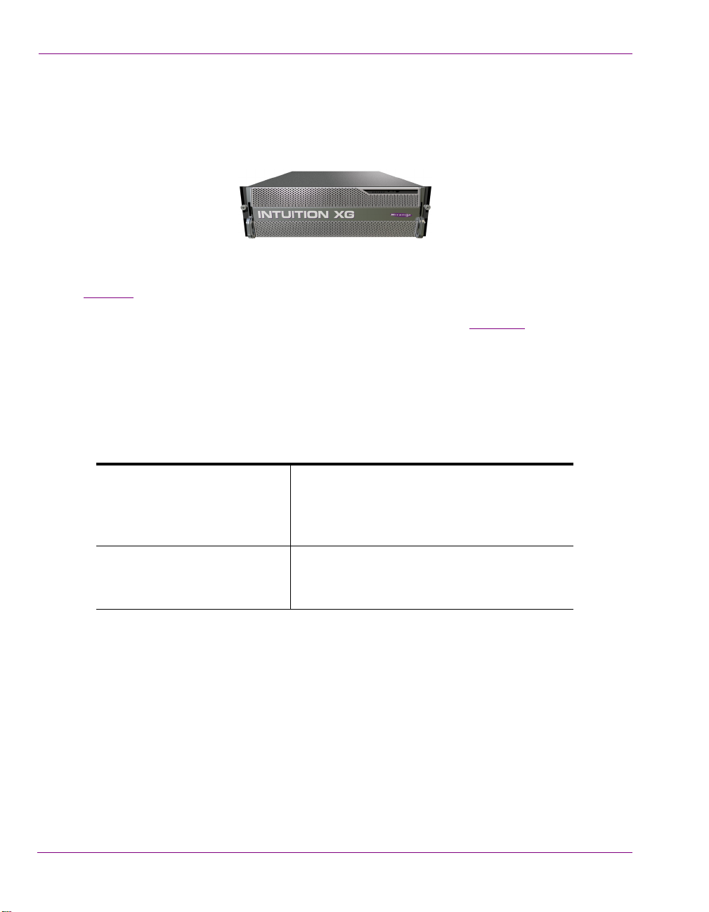
Intuition XG
Advanced HD/SD Graphics Processor
M848-9002-500
Page 2

Copyright & Trademark Notice
Copyright © 2015, Grass Valley USA, LLC. All rights reserved.
Belden, Belden Sending All The Right Signals, and the Belden logo are trademarks or
registered trademarks of Belden Inc. or its affiliated companies in the United States and
other jurisdictions. Grass Valley USA, LLC, Miranda, Vertigo Suite, Vertigo XG and Xmedia
Server are trademarks or registered trademarks of Grass Valley USA, LLC. Belden Inc.,
Grass Valley USA, LLC, and other parties may also have trademark rights in other terms
used herein.
Terms and Conditions
Please read the following terms and conditions carefully. By using the Intuition XG
documentation, you agree to the following terms and conditions.
Grass Valley hereby grants permission and license to owners of the Intuition XG to use their
product manuals for their own internal business use. Manuals for Grass Valley, A Belden
Brand products may not be reproduced or transmitted in any form or by any means,
electronic or mechanical, including photocopying and recording, for any purpose unless
specifically authorized in writing by Grass Valley.
A Grass Valley manual may have been revised to reflect changes made to the product
during its manufacturing life. Thus, different versions of a manual may exist for any given
product. Care should be taken to ensure that one obtains the proper manual version for a
specific product serial number.
Information in this document is subject to change without notice and does not represent a
commitment on the part of Grass Valley.
Warranty Policies
Warranty information is available in the Support section of the Grass Valley Web site
(www.grassvalley.com).
Document Identification
Title Intuition XG Configuration Guide
Part number M848-9002-500
SW version Vertigo Suite v5.0
Page 3

Revision History
After the original release date, this document may be updated with edits and then rereleased. The following table tracks the versions of this document.
Revision date Description
November 28, 2014 Original release
March 02, 2015 Vertigo Suite v5.0 SP1 release
Page 4

TABLE OF CONTENTS
Introduction .......................................................................................................................... 1-1
Intuition XG’s standard and optional features....................................................................................1-2
Intuition XG system integration.......................................................................................................... 1-6
Upstream branding using the Intuition XG......................................................................................... 1-7
Overview of the Intuition XG’s Hardware .......................................................................... 2-1
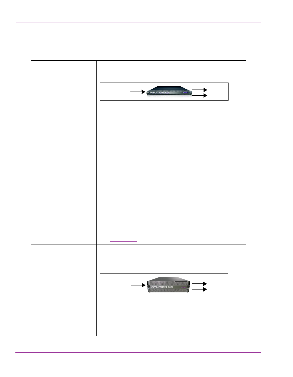
Hardware overview (Intuition-XG-e) .................................................................................................. 2-2
Front panel components (Intuition-XG-e)...................................................................................... 2-3
Rear panel components (Intuition-XG-e) ...................................................................................... 2-5
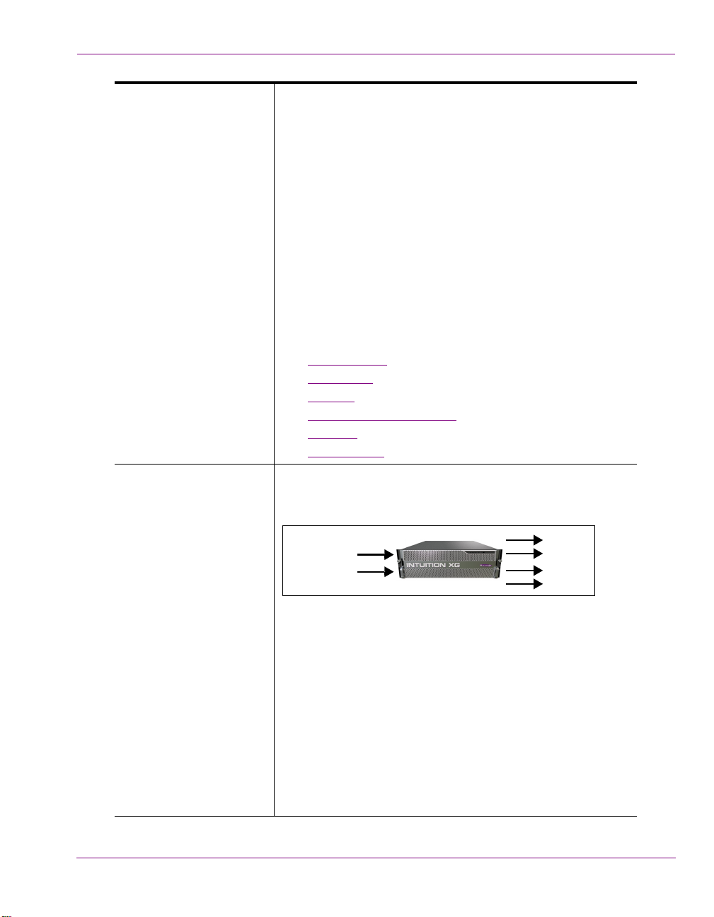
Hardware overview (Intuition-XG-3U-e / Dual-e) ............................................................................... 2-8
Front panel components (Intuition-XG-3U-e / Dual-e) .................................................................. 2-9
Rear panel components (Intuition-XG-3U-e / Dual-e)................................................................. 2-11
Intuition XG’s signal path and rendering processes ........................................................................ 2-16
Video input/output channels ....................................................................................................... 2-17
Audio input/output channels ....................................................................................................... 2-18
Ancillary data processing............................................................................................................ 2-19
Clip Player and media storage.................................................................................................... 2-19
Graphics processing ................................................................................................................... 2-20
Intuition XG’s Desktop Applications & Tools.................................................................... 3-1
Intuition XG’s desktop - device identification ..................................................................................... 3-2
Intuition XG Control Panel and XG Dashboard ................................................................................. 3-3
Xplay - Playout control application..................................................................................................... 3-5
Device Manager............................................................................................................................ 3-6
Automation Configuration ............................................................................................................. 3-8
Xplay’s Automation settings.......................................................................................................... 3-9
Vertigo Command Shell................................................................................................................... 3-10
Windows Explorer............................................................................................................................ 3-12
Embedded Xmedia Server Control Panel ................................................................................... 3-13
XPublish Agent Control Panel ....................................................................................................3-15
Data Server Control Panel.......................................................................................................... 3-16
Intuition XG Portal - Intuition XG’s Remote Configuration Tool...................................... 4-1
Accessing and logging into the Intuition XG Portal............................................................................ 4-2
Overview of the Intuition XG Portal’s menu commands .................................................................... 4-4
Remotely shutting down the Intuition XG device ............................................................................... 4-6
Restarting the Intuition XG device remotely ...................................................................................... 4-7
Viewing the processes running on the Intuition XG device................................................................ 4-8
Configuring Intuition XG’s network settings....................................................................................... 4-9
Specifying the Intuition XG device’s hostname................................................................................ 4-11
Specifying the Intuition XG device’s Date & Time settings .............................................................. 4-12
Logging off of the Intuition XG Portal............................................................................................... 4-13
Dashboard - Intuition XG’s Local Configuration Software............................................... 5-1
Intuition XG Configuration Guide TOC-1
Page 5

Table of Contents
About the Dashboard..........................................................................................................................5-3
Starting Dashboard.............................................................................................................................5-4
An overview of the Dashboard’s interface components .....................................................................5-5
Dashboard’s menus and buttons........................................................................................................5-6
Device List ..........................................................................................................................................5-8
Loading and refreshing the device list ...........................................................................................5-9
Saving the device list .....................................................................................................................5-9
Restarting a device in the device list ...........................................................................................5-10
Monitoring the status of a device .................................................................................................5-10
Removing a device from the device list .......................................................................................5-10
Device Discovery Tool......................................................................................................................5-11
Performing a Manual Device Discovery.......................................................................................5-13
Performing an Automatic Device Discovery ................................................................................5-14
Device Profile page ..........................................................................................................................5-15
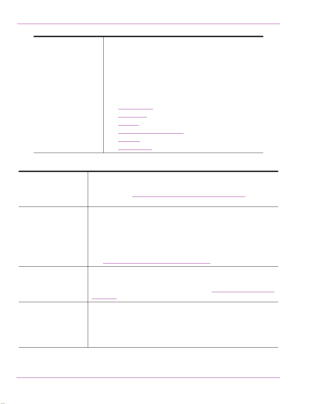
Device Settings tabs and configuration pages .................................................................................5-17
Device settings buttons................................................................................................................5-18
General page ...............................................................................................................................5-19
Resolution page...........................................................................................................................5-21
Live Window page .......................................................................................................................5-23
Clips page....................................................................................................................................5-25
3D Engine page ...........................................................................................................................5-27
Logging page ...............................................................................................................................5-29
Hardware Settings > Genlock page .............................................................................................5-31
Hardware Settings > Video page .................................................................................................5-34
Hardware Settings > Audio page .................................................................................................5-36
Hardware Settings > Ancillary page.............................................................................................5-38
Hardware Settings > Watch Dog page ........................................................................................5-41
Licensing page.............................................................................................................................5-42
Audio Mixing Profiles dialog box.......................................................................................................5-43
TOC-2 Intuition XG Configuration Guide
Page 6

1 INTRODUCTION
The Intuition XG graphics co-processor significantly extends the graphics and clip playout
capabilities of master control switcher systems, like the Imagestore 750 or NV51000MC, by
feeding the HD/SD fill/key inputs. It’s ideal for playout of the most advanced data-driven,
channel branding and promotional graphics, including: “Coming up next” and episodic
promos. The Intuition XG provides multi-level character generation plus animation/still and
clip playout with multi-channel audio.
The following sections of this configuration guide describe the Intuition XG’s features,
capabilities, and system integration:
Intuition XG’s standard and optional features” on page 1-2
• “
• “Intuition XG system integration” on page 1-6
• “Upstream branding using the Intuition XG” on page 1-7
• “The Intuition XG provides advanced branding capabilities to master control switchers”
on page 1-7
Further chapters provide descriptions of the Intuition XG’s hardware and software
components:
Overview of the Intuition XG’s Hardware” on page 2-1
• “
• “Intuition XG’s Desktop Applications & Tools” on page 3-1
Most Intuition XG devices are installed and configured by qualified network administrators
or Grass Valley’s Integration Specialists using the Intuition XG Portal and Dashboard
software interfaces. While we do not recommend that users change the Intuition XG’s
settings, the following chapters provide detailed descriptions of each of the Intuition XG
settings:
Intuition XG Portal - Intuition XG’s Remote Configuration Tool” on page 4-1
• “
• “Dashboard - Intuition XG’s Local Configuration Software” on page 5-1
Intuition XG Configuration Guide 1-1
Page 7
Introduction
Video In A
Out A
Fill
Key
Video In A
Out A
Fill
Key
Intuition XG’s standard and optional features
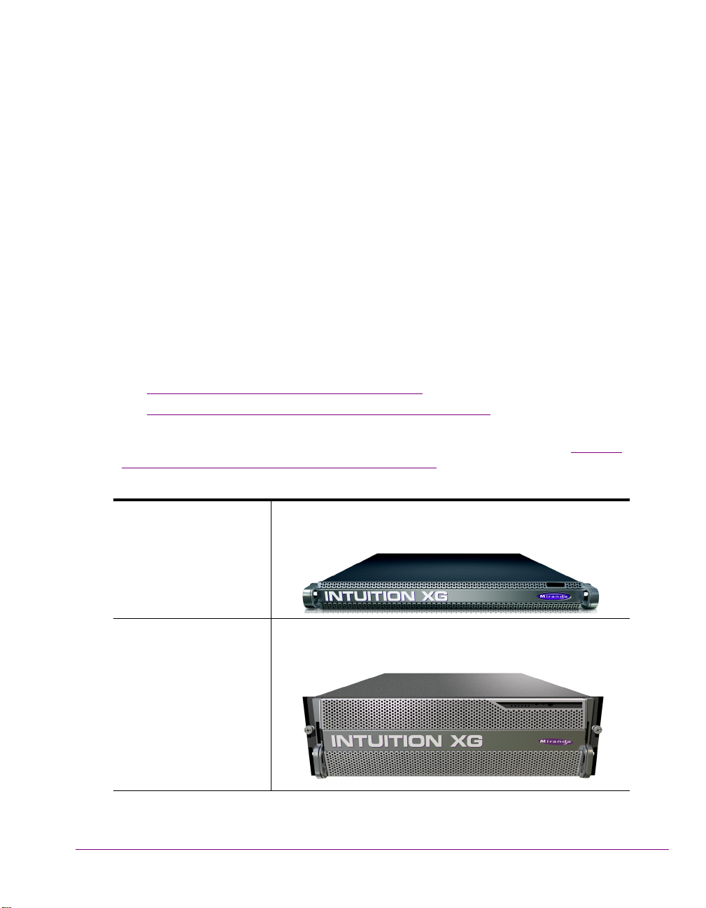
The Intuition XG is available in three (3) standard models:
Intuition-XG-e A single channel graphics co-processor, generally used
upstream of a master control switcher like the Imagestore 750
or NV5100MC.
• 1RU chassis with a single power supply unit.
• 1 HD/SD video input, 1 HD/SD (Fill & Key) output
• A powerful, HD/SD character generator which allows the
playout of virtually unlimited layers of animated text and
dynamically updated text.
• 1 TB RAID1 storage for up to 200 hours of video/audio
clips and simultaneous playout of multiple clips
• Playout of up to eight (8) layers of animated and still
graphics templates for the most advanced branding and
promotional effects.
• SD output as NTSC or PAL
• HD output as 1080i, 720p or 480p
• VANC + VBI extraction processing and insertion or
VAnc/VBI pass through.
• Full automation control by serial, Ethernet and/or GPI
commands.
Options
• VX-ClipPlayer
• VX-Audio-e
Intuition-XG-3U-e A single channel graphics co-processor, generally used
upstream of a master control switcher like the Imagestore 750
or NV5100MC.
• 3RU chassis with redundant power supply unit.
• 1 HD/SD video input, 1 HD/SD (Fill & Key) output
• A powerful, HD/SD character generator which allows the
playout of virtually unlimited layers of animated text and
dynamically updated text.
1-2 Intuition XG Configuration Guide
Page 8
• 1 TB RAID1 storage, or upgrade to 2 TB for up to 400
Video In A
Out A
Fill
Key
Out B
Fill
Key
Video In B
hours of video/audio clips and simultaneous playout of
multiple clips
• Playout of up to eight (8) layers of animated and still
graphics templates for the most advanced branding and
promotional effects.
• SD output as NTSC or PAL
• HD output as 1080i, 720p or 480p
• VANC + VBI extraction processing and insertion or
VAnc/VBI pass through.
• 16 embedded audio channels
• Discrete AES audio channels - up to 8 in and 16 out
• Full automation control by serial, Ethernet and/or GPI
commands.
Options
• VX-ClipPlayer
• VX-Audio-e
• VX-EAS
• VX-GPI-8-eVX-RS422-2-e
• VX-TC-e
• VX-2TB-UPG
Introduction
Intuition-XG-Dual-e A dual channel graphics co-processor, generally used
upstream of a master control switcher like the Imagestore 750
or NV5100MC.
• 3RU chassis with redundant power supply unit.
• 2 HD/SD video input, 2 HD/SD (Fill & Key) output
• A powerful, HD/SD character generator which allows the
playout of virtually unlimited layers of animated text and
dynamically updated text.
• TB RAID1 storage, or upgrade to 2 TB for up to 400 hours
of video/audio clips and simultaneous playout of multiple
clips
• Playout of up to eight (8) layers of animated and still
graphics templates for the most advanced branding and
promotional effects.
• SD output as NTSC or PAL
Intuition XG Configuration Guide 1-3
Page 9
Introduction
The following options are available on Intuition XG devices:
VX-ClipPlayer Clip Player
The Clip Player is an internal codec package for playing out multi-format
video clips. See “Clip Player and media storage” on page 2-19 for more
information about the Clip Player option.
• HD output as 1080i, 720p or 480p
• VANC + VBI extraction processing and insertion or
VAnc/VBI pass through.
• 16 embedded audio channels per SDI stream
• Discrete AES audio channels - up to 8 in and 2 x 16 out
• Full automation control by serial, Ethernet and/or GPI
commands.
Options
• VX-ClipPlayer
• VX-Audio-e
• VX-EAS
• VX-GPI-8-eVX-RS422-2-e
• VX-TC-e
• VX-2TB-UPG
VX-Audio-e Audio Processing
The discrete audio I/O card allows the Intuition XG to capture, process and
output discrete audio. The number of discrete audio I/O channels depends
on the model of Intuition XG:
• Intuition-XG-e => None
• Intuition-XG-3Ue and Intuition-XG-Dual-e => 8 in / 16 out
Audio input/output channels” on page 2-18 for more information.
See “
VX-GPI-8-e GPI card
The GPI card allows for control of the Intuition XG via GPI triggers. The
card allows for up to 8 GPI in and 8 GPI out. See “
page 2-15 for more information about the GPI card option.
VX-EAS EAS Text Integration (EAS Plugin and EAS Software Panel)
High quality EAS text and audio can be played out with the Intuition XG
processor, using templates which integrate channel branding graphics for
a consistent on-air presentation.
Only available for the Intuition-XG-3U-e and Intuition-Dual-e models.
1-4 Intuition XG Configuration Guide
GPI Card Connector” on
Page 10

VX-RS422-2-e 2 port RS-422 card
The RS-422 card provides an interface upon which the Intuition XG can
communicate with automation systems. See “RS-422 Connectors” on page
2-13 for more information.
Only available for the Intuition-XG-3U-e and Intuition-Dual-e models.
VX-TC-e Time Code card
The Time Code card allows you to lock the Intuition XG’s system clock to
an external timecode. See “
information about the Time Code option.
Only available for the Intuition-XG-3U-e and Intuition-Dual-e models.
VX-2TB-UPG 1 TB RAID-10 Expansion option (2 x 1TB)
Increases the usable storage from 1TB to 2TB. See “
storage” on page 2-19 for more information.
Only available for the Intuition-XG-3U-e and Intuition-Dual-e models.
Time Code Card” on page 2-13 for more
Introduction
Clip Player and media
Intuition XG Configuration Guide 1-5
Page 11
Introduction
Media Transfers
LAN / WAN
(ingest & publish)
Automation
PCS & PresStation
RCP-BR
Video/
audio
routing
Xplorer
Manual/Operator-controlled
Automation controlled
Master Control
Program Video Input
Master Control Switcher & Branding
Graphics co-processor
Centralized Asset Management
Media Management
Graphics Preparation
Photoshop, Premiere
Xstudio Xbuilder
or Final Cut
SDI input A
SDI input B
Program
Output
Fill
+
embedded
audio
Key
After Effects Plugin
Automation
protocol
Video IN
Intuition XG system integration
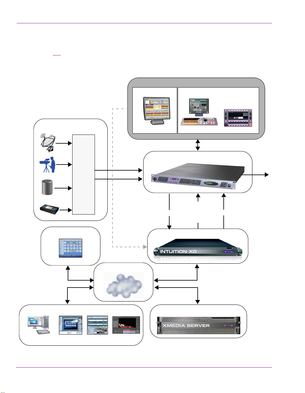
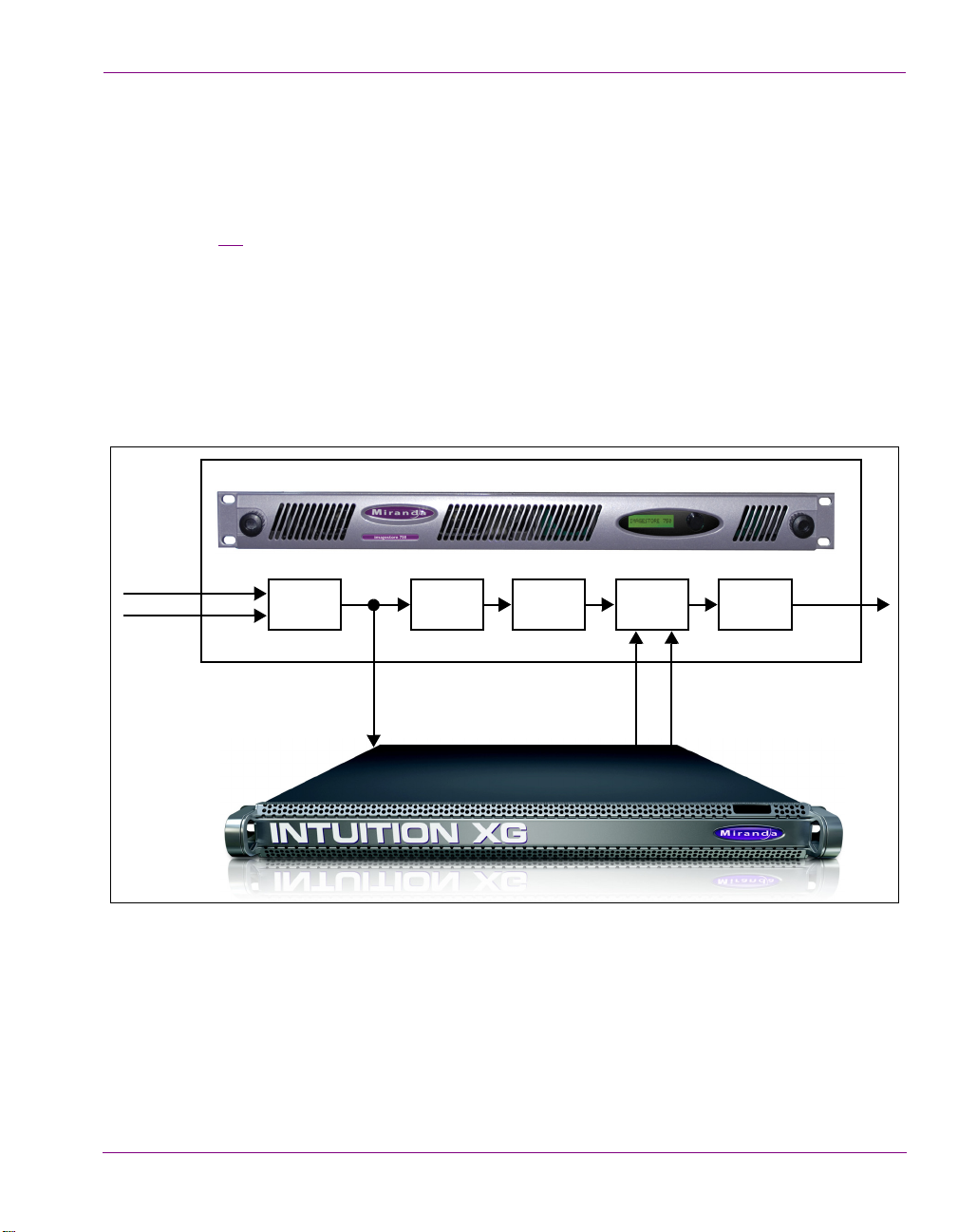
Figure 1-1 demonstrates that the Intuition XG can be fully integrated with Imagestores or
3rd party master control switchers, the Vertigo Suite, playout automation, and media
management systems.
Figure 1-1. The Intuition XG integrates with master control switchers and the Vertigo Suite products
1-6 Intuition XG Configuration Guide
Page 12
Upstream branding using the Intuition XG
Keyer 1
A/B
Mixer
Keyer 3Keyer 2 Keyer 4
Video IN A
Video IN B
Key
Fill &
embedded
audio
Clean Feed
Out
Video OUT
With its powerful rendering engine, the Intuition XG is able to generate and deliver
sophisticated multi-layered branding graphics as HD/SD fill and key inputs to master control
switchers, like the Imagestore 750 or NV5100MC.
Figure 1-2
video sources is conserved and the clean video feed is simultaneously pushed through the
master control switcher and the Intuition XG. Feeding the video signal into the Intuition XG
allows you to produce even more sophisticated branding events using dynamic DVEs, like
picture-in-picture and squeeze-and-reveal transitions. If for some reasons the Intuition XG
were to go down, graphics insertion would be lost, but the video signal is conserved without
interruption since the video feed continues to run through the master control switcher. Note
that for the video signal to be synchronized, you must specify a video frame delay on the
master control switcher (see V
demonstrates that the master control switcher’s ability to switch between two
IDEO FRAME DELAYS in the Imagestore 750 documentation).
Introduction
Figure 1-2. The Intuition XG provides advanced branding capabilities to master control switchers
Intuition XG Configuration Guide 1-7
Page 13

Introduction
1-8 Intuition XG Configuration Guide
Page 14
2 OVERVIEW OF THE INTUITION XG’S
ARDWARE
H
Depending upon the model, the Intuition XG device is either a 1 RU or 3 RU rackmount
chassis. The following sections describe the hardware components associated with each
model of the Intuition XG:
Hardware overview (Intuition-XG-e)” on page 2-2
• “
• “Hardware overview (Intuition-XG-3U-e / Dual-e)” on page 2-8
Despite the physical difference in chassis size and hardware options, each model of the
Intuition XG follows the same theory of operation as a graphics co-processor (see “Intuition
XG’s signal path and rendering processes” on page 2-16 for more details).
Intuition-XG-e A single channel (fill + key) output graphics co-processor in a
1 RU chassis.
Intuition-XG-3U-e
Intuition-XG-Dual-e
Intuition XG Configuration Guide 2-1
A single or dual channel (fill + key) output graphics coprocessor in a 3 RU chassis.
Page 15
Overview of the Intuition XG’s Hardware
Hardware overview (Intuition-XG-e)
The Intuition XG-e is a single HD/SD channel playout server (1 HD/SD video input, 1 HDSDI Fill + Key output) that incorporates the Vertigo XG graphics engine to rendering
advanced graphics. Physically, the Intuition XG is a 1RU rackmount playout server with a
single power supply unit and 1 TB of storage.
The following sections provide more information about Intuition XG’s hardware
components:
Front panel components (Intuition-XG-e)” on page 2-3
• “
• “Rear panel components (Intuition-XG-e)” on page 2-5
Chassis FORM: 1U rackmount chassis
H
EIGHT: 1.7” (43 mm)
WIDTH: 17.2” (437 mm)
DEPTH: 28.2” (716 mm)
Power consumption 1 x 1400W power supply
• AC input: 180 - 240V, 50 - 60 Hz, 7.2 - 9.5 Amp
2-2 Intuition XG Configuration Guide
Page 16
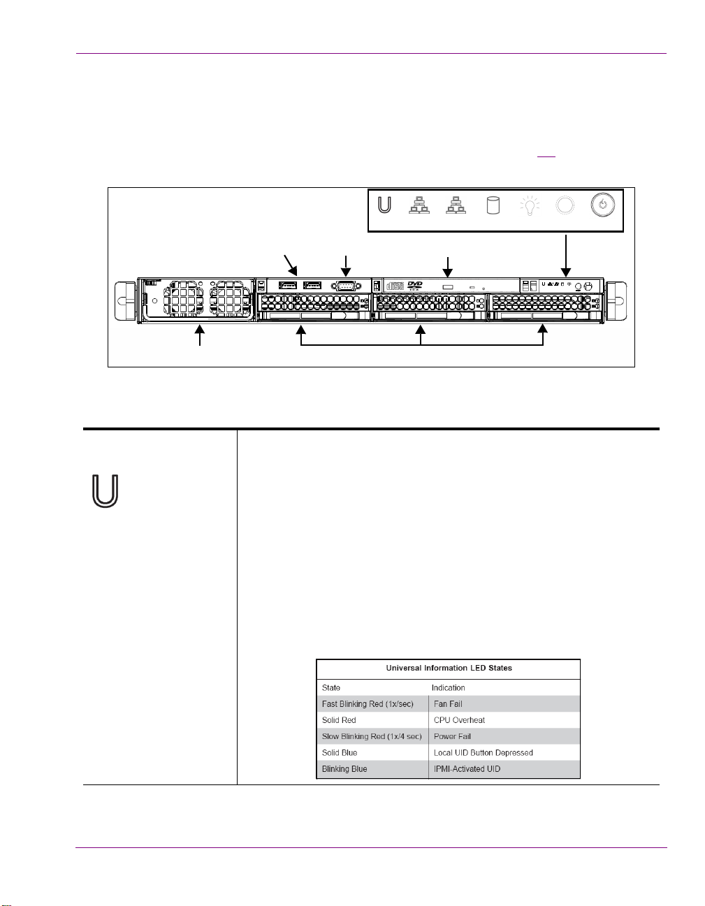
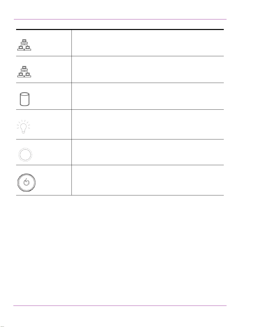
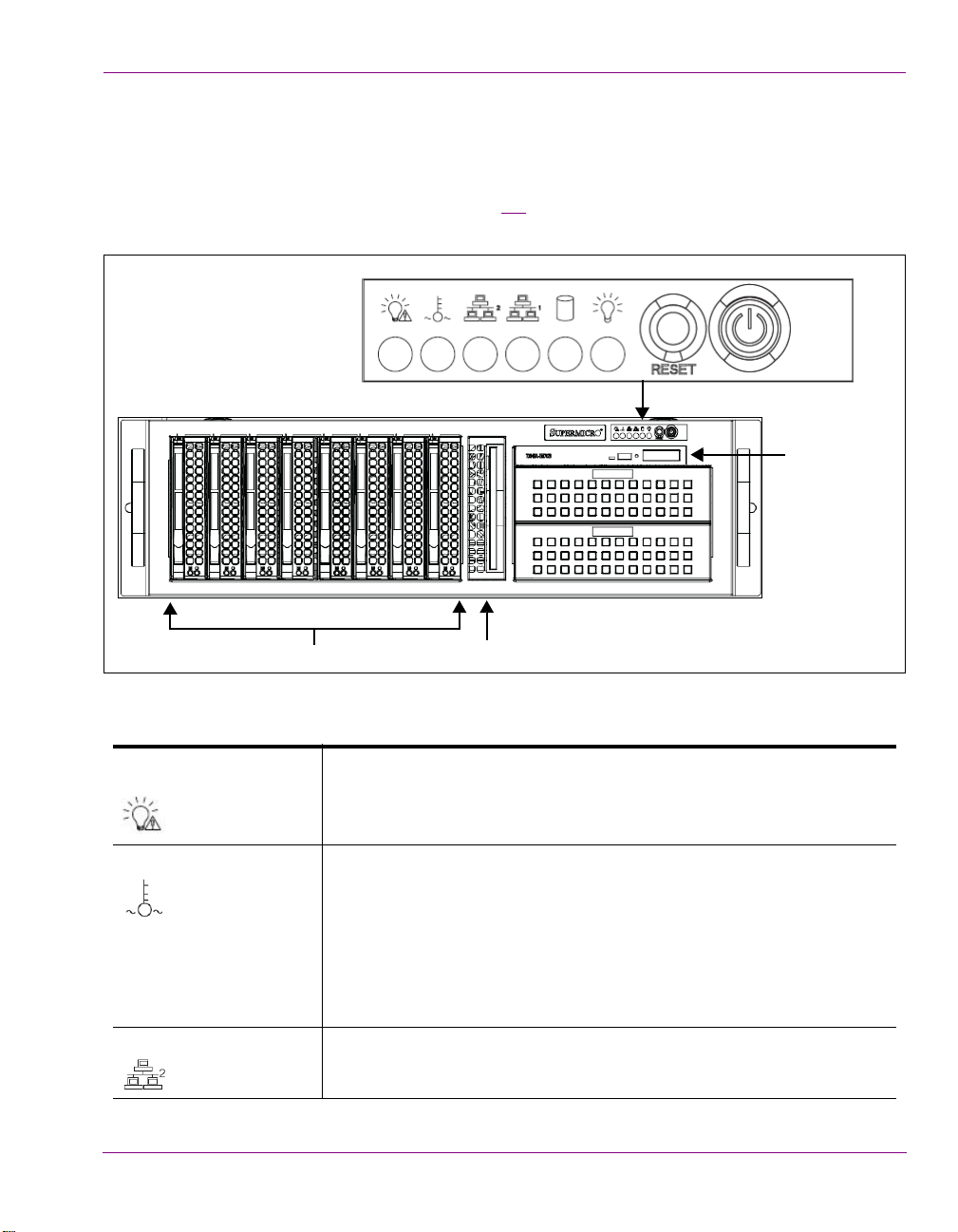
Front panel components (Intuition-XG-e)
Control Panel
LEDs & Buttons
CD/DVD ROM Drive
SATA Hard Drives
21
Reset Power On/OffPower LEDHDD LEDNIC 2 LED NIC 1 LEDUniversal
Info. LED button button
USB 2.0
Connectors (2)
RS-232 Serial Port
(Disabled)
Power Supply Unit
The Intuition XG’s front panel features convenient access to the SATA hard drives, two USB
ports, a CD/DVD ROM drive, two fans, and a control panel containing five LEDs and two
buttons for system monitoring and operation. The table following the figure 2-1
the function of each LED and button.
Figure 2-1. Intuition XG’s front panel components
U
NIVERSAL INFORMATION
LED
The Universal Information LED is used to indicate fan failure, power
failure, overheat condition, or to identify the unit within a large rack
installation. The feature requires a motherboard that supports the
Universal Information LED.
When this LED blinks red quickly, it indicates a fan failure and when
blinking red slowly a power failure. This LED will be blue when used for
UID (Unit Identifier). When on continuously red, it indicates an overheat
condition, which may be caused by cables obstructing the airflow in the
system or the ambient room temperature being too warm. See the table
below for descriptions of the LED states.
Note: Deactivating the UID LED must be performed in the same way it was
activated. (If the UID LED was activated via IPMI, you can only turn the
LED off via IPMI and not with the UID button.)
Overview of the Intuition XG’s Hardware
describes
Intuition XG Configuration Guide 2-3
Page 17
Overview of the Intuition XG’s Hardware
2
1
NIC2 A flashing NIC2 LED indicates network activity on LAN2.
NIC1 A flashing NIC1 LED indicates network activity on LAN1.
HDD Indicates IDE channel activity.
OWER (LED) Indicates that power is being supplied to the system’s power supply units.
P
This LED should normally be illuminated when the system is in operation.
R
ESET The Reset button reboots the system.
OWER (BUTTON) This is the main power button, which is used to apply or turn off the main
P
system power. Turning off this button removes the main power, but keeps
standby power supplied to the system.
2-4 Intuition XG Configuration Guide
Page 18
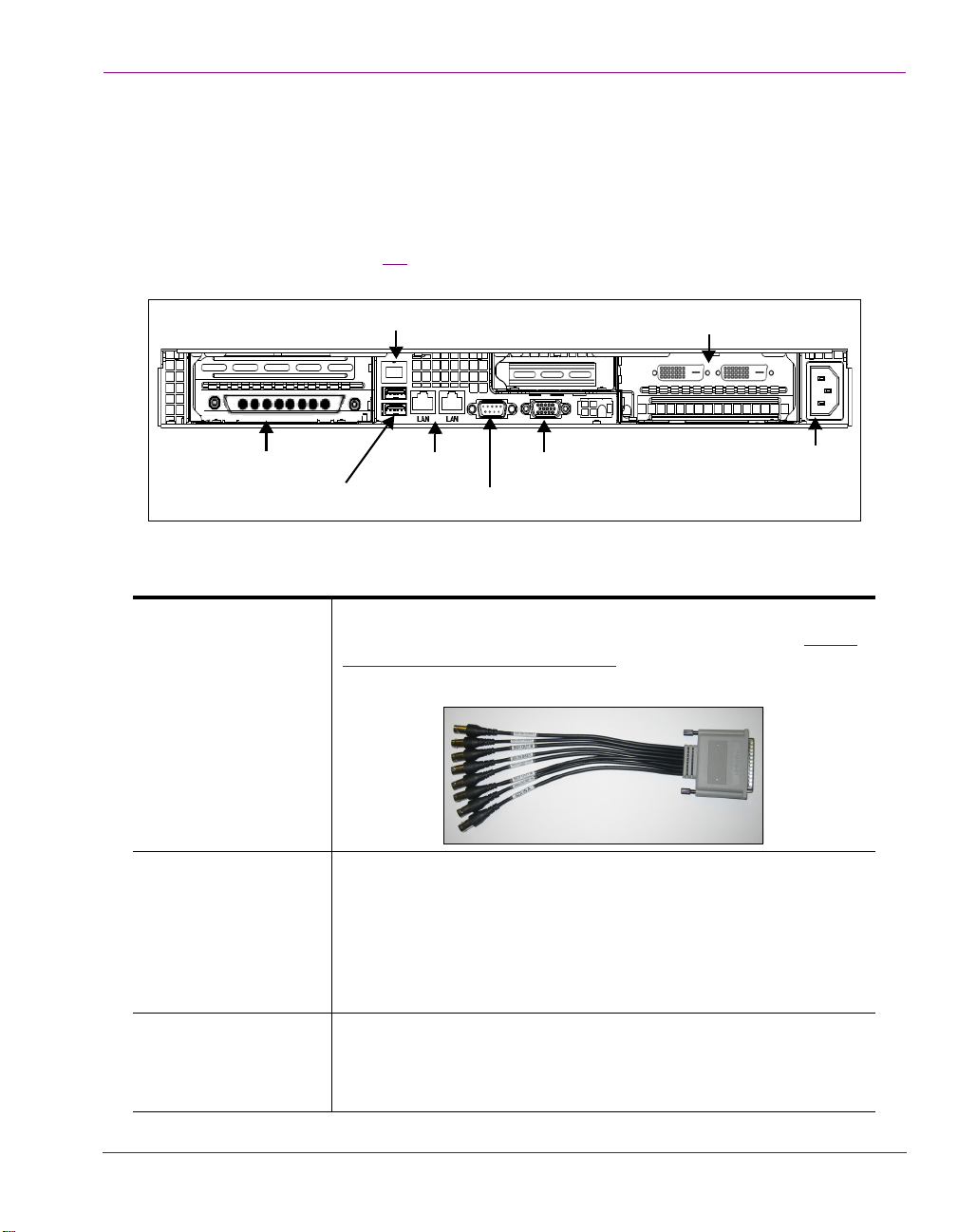
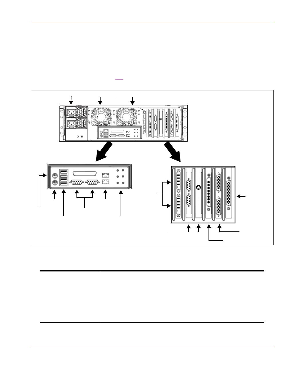
Rear panel components (Intuition-XG-e)
A/C Power Input
Graphics Card Connectors (2)
USB 2.0 Connectors (2)
IPMI Connector
Network Ethernet
Connectors (2)
VGA Connector
(Disabled)
Serial RS-232 Port
(Not used)
(Mouse & Keyboard)
(Only one connector used)
SDI Video Card I/O Connector
The Intuition XG’s rear panel features convenient access to the video card’s I/O connector,
which provides 1 SD/HD SDI video input, 1 SD/HD SDI video output (Fill & Key), and a
reference signal input. The rear panel also provides access to the graphics card connector,
as well as various I/O ports (RS-422, USB, Ethernet...etc.).
The table following the figure 2-2
of the Intuition XG chassis.
Figure 2-2. The Intuition XG’s rear panel components
describes the function of each connector on the rear panel
Overview of the Intuition XG’s Hardware
SDI Video Card I/O
Connector
A breakout cable is used to connect the Video Card I/O connector to
the SDI video input/output cables and the reference I/O. See “
input/output channels” on page 2-17 for more information about the
Intuition XG’s video input/output channel connections.
IPMI Connector Intelligent Platform Management Interface is a set of common
interfaces to a computer system which system administrators can use
to monitor system health and manage the system. IPMI operates
independently of the operating system and allows administrators to
manage a system remotely even in the absence of an operating
system or the system management software, or even if the monitored
system is powered off.
USB 2.0 Connectors The two (2) USB 2.0 connectors on the rear panel allow you to connect
a mouse and keyboard to the Intuition XG device. These peripherals
are required during the device’s initial configuration, which involves
using the Intuition XG’s desktop applications, including Dashboard.
Intuition XG Configuration Guide 2-5
Video
Page 19
Overview of the Intuition XG’s Hardware
Network Ethernet
Connectors
Serial RS-232 Port The two (2) RS-232 connectors provide two control ports upon which
The two (2) Network Ethernet connectors are teamed and allow you to
connect the Intuition XG device to the Local Area Network (LAN).
NIC Teaming is a networking concept where multiple network
adapters within a computer are combined in parallel to provide
redundancy for the network interface. On an Intuition XG device, the
two Local Area Connection network adapters are teamed together
(connect 2 cables to the 2 NIC cards at the same time) to form a third
virtual adapter. In the event of an adapter, cable or switch failure, the
network interface fails over to the healthy adapter.
When the individual Local Area Network adapters are teamed
together the individual Local Area Network adapters are not
accessible or configurable. Only the teamed virtual adapter can be
configured.
If you only have 1 cable connected, then the teaming will still be in
effect but all traffic will be over that one cable. If that NIC fails, you will
have to manually move the cable to the other NIC.
the automation system’s serial cables are connected. It is through this
connection that the automation system communicates and controls
the Vertigo XG using automation protocol commands.
VGA Connector This VGA connector is disabled since the Intuition XG’s graphics card
connector allows you to connect to a monitor to view the Intuition XG
desktop.
2-6 Intuition XG Configuration Guide
Page 20
Overview of the Intuition XG’s Hardware
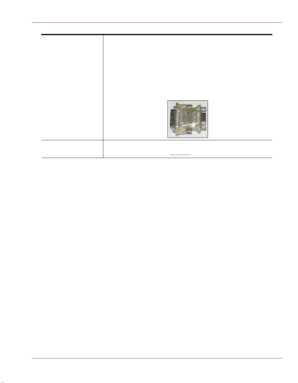
Graphics Card’s DVI
Connectors
Power Supply The power cord connects to Intuition XG’s 1400 W power supply. See
The graphics card’s DVI connectors allow you to connect the
Vertigo XG device to DVI monitor. The monitor is only required during
the device’s initial configuration, so as to display Vertigo XG’s desktop
applications, including XG Dashboard.
Note that although there are two (2) DVI connectors, the Vertigo XG
can display to only one monitor. Therefore, it does matter which of the
two connectors the monitor’s cable is connected to.
Use the adapter (below) if you would rather connect a VGA monitor.
the specifications listed on page 2-1
.
Intuition XG Configuration Guide 2-7
Page 21
Overview of the Intuition XG’s Hardware
Hardware overview (Intuition-XG-3U-e / Dual-e)
Physically, the Intuition XG-3U-e and Intuition XG-Dual-e are 3RU rackmount rendering
platforms that incorporate redundant fans, three power supplies, and 1 TB RAID-1 enabled
storage (optional 2 TB RAID-10 expansion).
The Intuition XG (3U & Dual) features easy frontal access to the SCSI drives, two UBS ports
and a control panel featuring LEDs and buttons for system monitoring and operation (see
page 2-9 for more details). The rear panel also provides convenient access to two power
supply modules, six PCI expansion slots which contain the video, audio, and graphics
cards, and various I/O ports (USB, COM1, VGA, Ethernet...etc). See page 2-11 for more
details about the Intuition XG’s rear panel components and connectors.
The following hardware options are also available to enhance the performance and
capabilities of the Intuition XG:
• VX-RS422-e (2 port RS-422/485 PCI card)
• VX-GPI-8-e (GPI card)
• VX-TC-e (Time Code card)
• VX-2TB-UPG (1TB RAID10 expansion drive)
Chassis F
Power consumption AC input: 100 - 240V, 50 - 60 Hz
2-8 Intuition XG Configuration Guide
ORM: 3U rackmount chassis
EIGHT: 5.2” (132 mm)
H
IDTH: 17.7” (450 mm)
W
DEPTH: 25.5” (648 mm)
Consumption: 4.05 - 1.73A
Power: 410 max.
Page 22
Overview of the Intuition XG’s Hardware
POWER
CD/DVD ROM Drive
Hard Drives
Floppy
Drive
Front panel components (Intuition-XG-3U-e / Dual-e)
The Intuition XG’s front panel features convenient access to the hard drives, a CD/DVD
ROM drive, and a control panel containing six LEDs and two buttons for system monitoring
and operation. The table following the figure 2-3
button.
describes the function of each LED and
Figure 2-3. The Intuition XG’s front panel components
YSTEM ALERT / POWER
S
FAILURE
Indicates a power supply module has failed, which is accompanied by an
audible alarm. A backup power supply module will take the load and keep
the system running, but the failed module will need to be replaced. This
red LED should be off when the system is operating normally.
OVERHEAT / FAN FAIL When this red LED flashes, it indicates a fan failure. When it is constantly
illuminated (solid on), it indicates an overheat condition, which may be
caused by cables obstructing the airflow in the system or the ambient room
temperature being too warm. Check the routing of cables and make sure
that all fans are present and operating normally. You should also check to
make sure that the chassis covers are installed properly. Finally, verify that
the heatsinks are installed properly. This LED will remain flashing or on as
long as the above mentioned conditions exist.
LAN2 A flashing green LAN2 LED indicates network activity on LAN2.
Intuition XG Configuration Guide 2-9
Page 23

Overview of the Intuition XG’s Hardware
LAN1 A flashing green LAN1 LED indicates network activity on LAN2.
CTIVITY This flashing amber LED indicates IDE channel activity.
HDD A
OWER INDICATOR (LED) Indicates that power is being supplied to the system’s power supply units.
P
This green LED should normally be illuminated when the system is in
operation.
ESET The Reset button reboots the system.
R
OWER BUTTON This is the main power button, which is used to apply or turn off the main
P
system power. Turning off this button removes the main power, but keeps
standby power supplied to the system.
2-10 Intuition XG Configuration Guide
Page 24
Overview of the Intuition XG’s Hardware
Power Supply Modules (2)
RS-422 Connectors
USB 2.0
Network Ethernet
Connectors (2)
SDI Video Card
Connectors (4)
I/O Connector
Graphics Card
System Fans (2)
Serial
RS-232 Ports (2)
Mouse
Keyboard
Connectors (2)
(option)
Audio I/O Ports
(Disabled)
Discrete Audio
Connectors (2)
(option)
Connector
Connector
GPI Card Connector
(option)
Time Code
Card
LTC
IN
LTC
IN
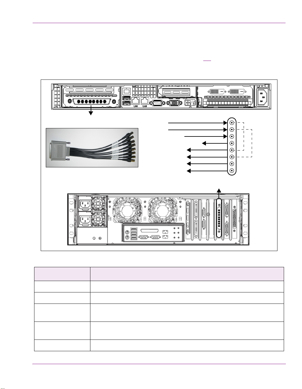
Rear panel components (Intuition-XG-3U-e / Dual-e)
The Intuition XG’s rear panel features convenient access to the video card’s I/O connector,
which provides up to 4 SD/HD SDI video outputs, a reference signal input, and AES audio
input/output. The rear panel also provides access to the graphics card connector, as well
as various I/O ports (RS-422, USB, Ethernet...etc.).
The table following the figure 2-2
of the Intuition XG chassis.
describes the function of each connector on the rear panel
Figure 2-4. The Intuition XG’s rear panel components
Mouse & Keyboard
connectors
The two (2) PS/2 connectors on the rear panel allow you to connect a
mouse and keyboard to the Intuition XG device. These peripherals are
required during the device’s initial configuration, which involves using
the Intuition XG’s desktop applications, including Dashboard.
Note that if the mouse or keyboard has a UBS connector, you can
connect them to the USB 2.0 connectors on the front or rear panels of
the Intuition XG device.
Intuition XG Configuration Guide 2-11
Page 25
Overview of the Intuition XG’s Hardware
USB 2.0 Connectors The four (4) USB 2.0 connectors on the rear panel allow you to
connect peripheral devices (e.g. keyboard, mouse, flash drive...etc) to
the Intuition XG.
Serial RS-232 Port The two (2) RS-232 connectors provide two control ports upon which
the automation system’s serial cables are connected. It is through this
connection that the automation system communicates and controls
the Intuition XG using automation protocol commands.
Network Ethernet
Connectors
Audio I/O ports These six (6) audio I/O ports are not supported by the Intuition XG
The two (2) Network Ethernet connectors are teamed and allow you to
connect the Intuition XG device to the Local Area Network (LAN).
NIC Teaming is a networking concept where multiple network
adapters within a computer are combined in parallel to provide
redundancy for the network interface. On an Intuition XG device, the
two Local Area Connection network adapters are teamed together
(connect 2 cables to the 2 NIC cards at the same time) to form a third
virtual adapter. In the event of an adapter, cable or switch failure, the
network interface fails over to the healthy adapter.
When the individual Local Area Network adapters are teamed
together the individual Local Area Network adapters are not
accessible or configurable. Only the teamed virtual adapter can be
configured.
If you only have 1 cable connected, then the teaming will still be in
effect but all traffic will be over that one cable. If that NIC fail, you will
have to manually move the cable to the other NIC.
since external audio input and output is provided by the Discrete EAS
option (see “
Audio input/output channels” on page 2-18).
2-12 Intuition XG Configuration Guide
Page 26
Overview of the Intuition XG’s Hardware
Graphics Card’s DVI
Connectors
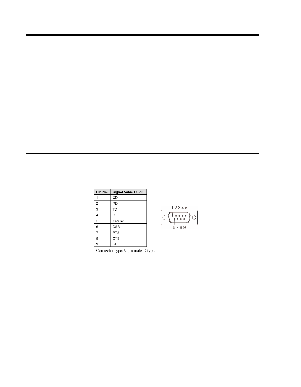
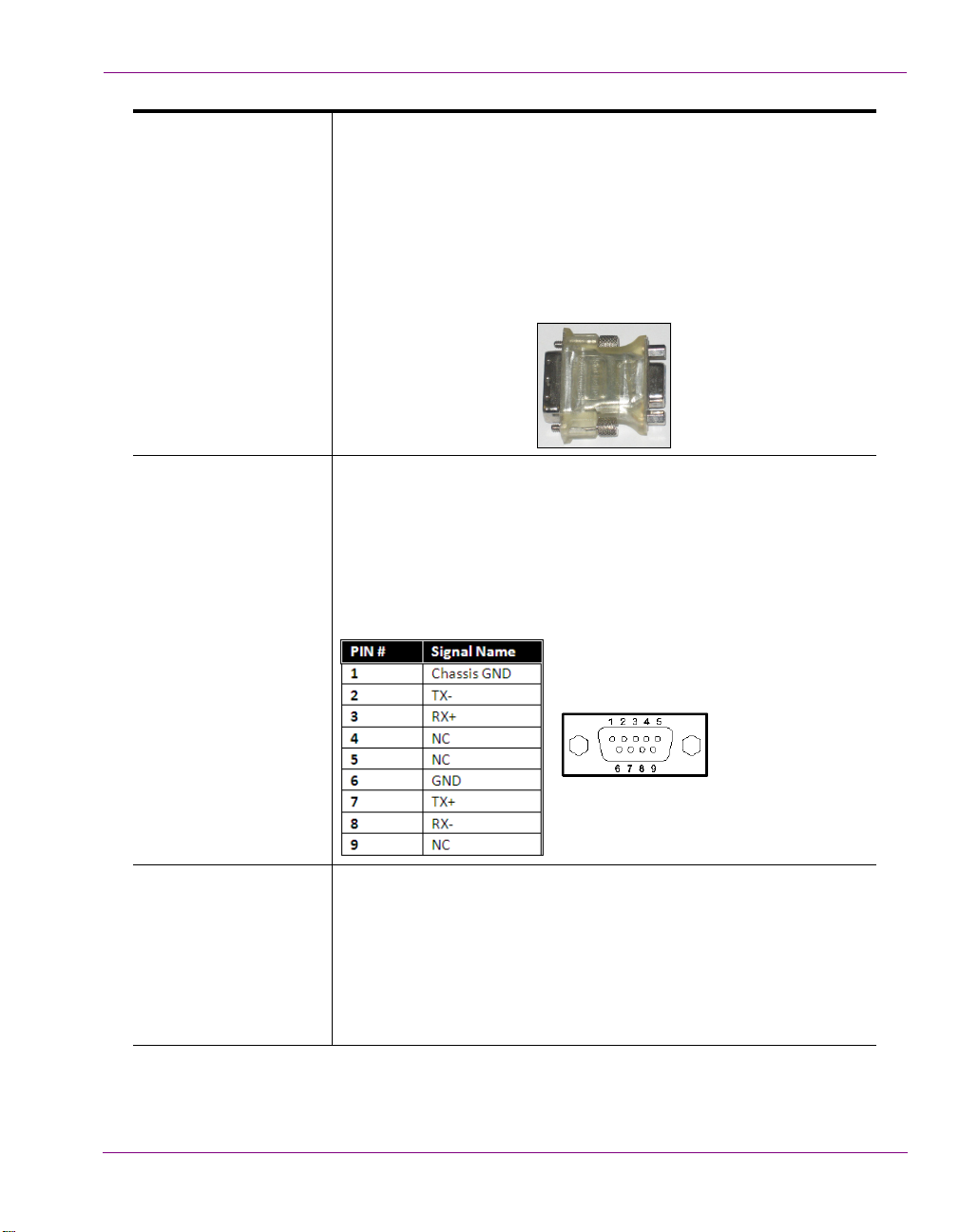
RS-422 Connectors Intuition XG hardware option: Vx-RS422-e
The graphics card’s DVI connectors allow you to connect the
Vertigo XG device to DVI monitor. The monitor is only required during
the device’s initial configuration, so as to display Intuition XG’s
desktop applications, including XG Dashboard.
Note that although there are two (2) DVI connectors, the Intuition XG
can display to only one monitor. Therefore, it does matter which of the
two connectors the monitor’s cable is connected to.
Use the adapter (below) if you would rather connect a VGA monitor.
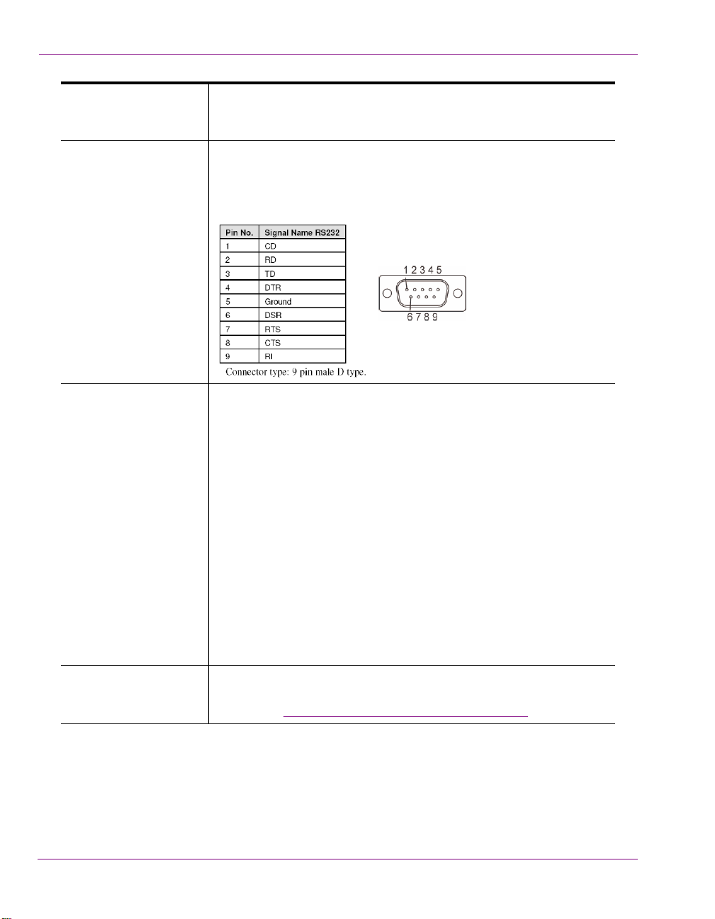
The RS-422 connectors provide two control ports upon which the
automation system’s serial cables are connected. It is through this
connection that the automation system communicates and controls
the Intuition XG using automation protocol commands.
The following represents the pinout assignments of the RS-422
connector:
Time Code Card Time Code Card option: VX-TC-e
The Time Code card allows you to lock the Intuition XG’s system clock
to an external timecode. The Time Code card reads Longitudinal Time
Code (LTC) from the signal present at the BNC connector.
The Time Code option ensures an accurate time stamp for system
logs. Accurate time is also required for time-based on-air graphics (i.e.
countdown clocks).
Intuition XG Configuration Guide 2-13
Page 27
Overview of the Intuition XG’s Hardware
SDI Video Card I/O
Connector
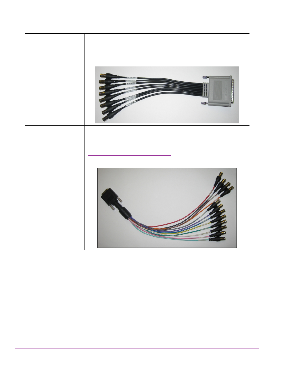
Discrete Audio
connectors
A breakout cable is used to connect the Video Card I/O connectors to
the SDI video input/output cables and the reference I/O. See “
input/output channels” on page 2-17 for more information about the
Intuition XG’s video input/output channel connections.
Intuition XG hardware option: Vx-Audio-e
A breakout cable is used to connect the optional discrete audio card
I/O connectors to the BNC audio input/output cables. See “Audio
input/output channels” on page 2-18 for more information about the
Vertigo XG’s discrete audio input/output channel connections.
Video
2-14 Intuition XG Configuration Guide
Page 28
Overview of the Intuition XG’s Hardware
Input Ports Pin Assignment Output Ports Pin Assignment
Power and Ground Pin Assignments
GPI Card Connector Intuition XG hardware option: Vx-GPI-8-e
The GPI card allows for control of the Intuition XG via GPI triggers.
The card provides for up to 8 optically isolated GPI inputs and 8 reed
relay GPI outputs.
Port A is an 8 bit input port connected to optically isolated inputs
sensors. Each sensor can be used to interface a voltage and then
sense whether the voltage is on or off.
The reed relays are well suited for low current applications. The relays
are normally open, and will close when energized.
The following tables identify the pinout assignment for the GPI card’s
input and output ports:
Intuition XG Configuration Guide 2-15
Page 29
Overview of the Intuition XG’s Hardware
Key (Output C)
Fill (Output A)
Media
Storage
RS-232
Relay Bypass A
SD/HD Channel 1
Input A
REF IN
GigE Media
Import
SD/HD Channel 1
Clip Player
Ancillary
Data
Compositor
Rendering A
DVE & Keyer
Genlock
Relay Bypass B
Processing
Controller
SD/HD Channel 1
(1 TB)
SD/HD Channel 2
Input B
Audio
Embedder
Fill (Output B)
Key (Output D)
SD/HD Channel 2
SD/HD Channel 2
Virtual
Input
Switch
Audio
De-embedder
Rendering B
DVE & Keyer
Compositor
Media
Storage
(1 TB)
Additional
RS-422
(Optional)
Legend
3U & Dual only
Dual only
Audio Mixer & Processor
AES IN
AES OUT
AES IN
AES OUT
(channels 9-16)
(channels 1-8)
(ch. 1-4)
(ch. 5-8)
GPI-8 I/O
(Optional)
Audio
De-embedder
Audio
Embedder
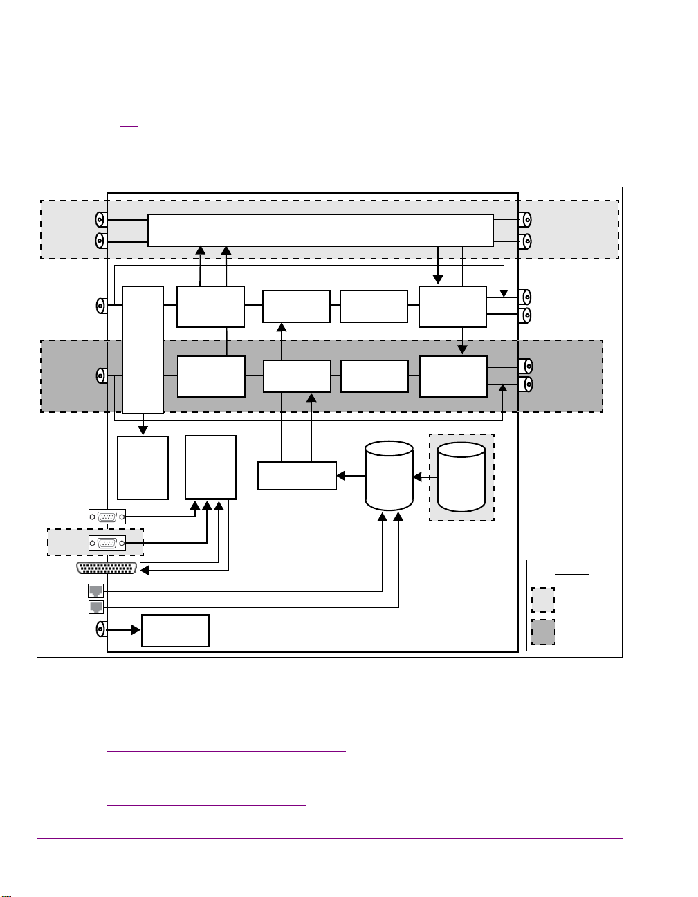
Intuition XG’s signal path and rendering processes
Figure 2-5 features a block diagram of the inputs, outputs and internal rendering processes
that are performed by the Intuition XG. Note that the block diagram illustrates the features
and functionality of all three models of the Intuition XG. Features and components that are
restricted to specific models are identified as such in the diagram or by the shading.
Figure 2-5. Block diagram of the Intuition-XG-3U-e and Intuition-XG-Dual-e
Additional information regarding the internal processing performed by the Intuition XG is
provided in the following topics:
Video input/output channels” on page 2-17
• “
2-16 Intuition XG Configuration Guide
• “Audio input/output channels” on page 2-18
• “Ancillary data processing” on page 2-19
• “Clip Player and media storage” on page 2-19
• “Graphics processing” on page 2-20
Page 30
Video input/output channels
Video breakout cable
SDI IN A
SDI IN B
ANALOG REF IN
ANALOG REF LOOP OUT
SDI OUT A (Fill 1)
SDI OUT B (Fill 2)
SDI OUT C / KEY
SDI OUT D / KEY
H/W Bypass
H/W Bypass
Channel 1
Channel 2
SDI Video Card I/O Connector
SDI Video Card I/O Connector
LTC
IN
SDI Video Card I/O Connector
Depending on the model, Intuition XG devices offer one or two video SD/HD input channels
with one or two video SD/HD fill and key output channels. Figure 2-6
identifies and describes the Intuition XG video card’s input and output connections,
including the hardware bypass.
Overview of the Intuition XG’s Hardware
and the following table
Pin/Channel Name Description
SDI IN A SDI IN A is the primary input channel connection.
SDI In B SDI IN B acts as a separate input channel on the Intuition-XG-Dual-e model.
ANALOG REF IN Analog Ref In is the input reference signal used by the Genlock hardware to
Figure 2-6. The Intuition XG video card’s input and output connections
synchronize the phase timing video and graphics processing.
ANALOG REF
LOOP OUT
Analog Ref Out loops the signal that comes in through the Analog Ref In
channel.
SDI OUT A SDI OUT A (Fill 1) is the primary output channel connection.
Intuition XG Configuration Guide 2-17
Page 31

Overview of the Intuition XG’s Hardware
Discrete audio breakout cable
AES IN 1/2
LTC
IN
AES IN 3/4
AES IN 5/6
AES IN 7/8
AES OUT 1/2
AES OUT 3/4
AES OUT 5/6
AES OUT 7/8
AES OUT 9/10
AES OUT 11/12
AES OUT 13/14
AES OUT 15/16
Pin/Channel Name Description
SDI Out B SDI OUT B (Fill 2) is the second output channel on the Intuition-XG-Dual-e
model. No signal is present at this connection for single-channel models.
SDI Out C / Key SDI OUT C is the matching Key channel for SDI OUT A.
SDI Out D / Key SDI OUT D is the matching Key channel for SDI OUT B, which is only available
on the Intuition-XG-Dual-e model.
No signal is present at this connection for single-channel models.
Audio input/output channels
The Intuition XG-3U-e and Intuition XG-Dual-e supports both embedded and discrete audio
channels. Each video input/output can contain up to 8 stereo pairs (16 channels) of
embedded audio.
The number of discrete audio input/output channels depends on the number of physical
inputs available. For each physical input available there will be a discrete audio breakout
cable (see figure 2-7
8 BNC outputs. Each BNC connector represents 1 stereo pair (2 channels) of digital
AES/EBU audio. Therefore, each discrete audio breakout cable contains 4 stereo pairs
(8 channels) of input and 8 stereo pairs (16 channels) of output.
). Each discrete audio breakout cable contains 4 BNC inputs and
Figure 2-7. Intuition XG’s discrete audio channels
2-18 Intuition XG Configuration Guide
Page 32

When capturing audio, the Intuition XG can capture embedded and discrete simultaneously,
however there are restrictions. The stereo pair cannot be captured from both sources at the
same time. For example, if only capturing pairs 1 & 2 from embedded, then pairs 1 & 2 are
not available from AES, but 3-8 are available.
The Intuition XG performs one-to-one passthrough of audio. All captured audio will be
broadcast on the corresponding outputs. For example, if the first 2 stereo pairs of
embedded audio on SDI IN A are captured, then the signal will be output as the first 2 stereo
pairs of embedded audio on SDI OUT A and simultaneously on AES discrete outputs 1 & 2.
Ancillary data processing
The Intuition XG reserves some hardware functionality for the extraction, processing, and
insertion of ancillary data into the output video signal, for example, Vertical Ancillary (VAnc)
data and Vertical Blanking Interval (VBI) data.
The ancillary data space can be used as a transport mechanism for data to be extracted by
the Intuition XG for triggering keyers, squeezes (DVEs) or other graphics events. Metadata
embedded upstream of the Intuition XG is extracted and processed by the control
application to control these actions.
Clip Player and media storage
Overview of the Intuition XG’s Hardware
The Intuition XG offers a video/audio clip player option that can output clips simultaneously.
It is ideal for the playout of full screen or partial screen clips, and the player supports
MPEG2 (I frame & Long GOP), MPEG-4 / H.264, DV25, DV50, DV100, IMX30, IMX40,
IMX50, MXF, GFX and AVI formats.
All models of the Intuition XG are equipped with a base 1 TB RAID1 storage. The Intuition
XG-3U-e and Intuition XG-Dual-e models offer an expandable RAID 10 storage option,
which increases the devices storage capacity from 1 TB to 2 TB (VX-2TB-UPG). The
following table demonstrates the storage capacities of clips in multiple formats using the
base and expanded storage configurations.
Clip storage with different storage options (hours)
Mbps
1 TB 2 TB
10 200 400
50 40 80
100 20 40
Intuition XG Configuration Guide 2-19
Page 33

Overview of the Intuition XG’s Hardware
Graphics processing
The Intuition XG’s multi-layered graphics engine supports the loading of multiple graphics
scenes on independently-controlled, dynamic layers. The number of layers to be controlled
is defined in the Xplay control application. A large number of graphics objects, including input
video, images, clips, cel animations, text, crawls, rolls, are supported all within a single
graphics layer (figure 2-8
scene using the authoring tool set and then loading the scene onto the Intuition XG device.
). Graphics output is created by positioning objects within a graphics
Figure 2-8. The Intuition XG supports the production of multi-layered graphics
2-20 Intuition XG Configuration Guide
Page 34

3 INTUITION XG’S DESKTOP
NOTE
A
PPLICATIONS & TOOLS
Connecting a VGA monitor, keyboard and mouse to the Intuition XG device’s rear panel
connectors (see page 2-5 or page 2-11) allows you to view and interact with the Intuition
XG’s desktop and software applications. Upon startup, the Intuition XG automatically opens
its desktop applications, which are used for configuring and controlling the Intuition XG
device locally. Once the device is properly configured, these applications are only needed
for maintenance. As such, the monitor, keyboard, and mouse can be disconnected.
The following sections describe the Intuition XG’s desktop appearance, as well as the
various software applications or tools that the Intuition XG makes available through its
desktop:
Intuition XG’s desktop - device identification” on page 3-2
• “
• “Intuition XG Control Panel and XG Dashboard” on page 3-3
• “Xplay - Playout control application” on page 3-5
• “Vertigo Command Shell” on page 3-10
• “Windows Explorer” on page 3-12
• “Embedded Xmedia Server Control Panel” on page 3-13
• “XPublish Agent Control Panel” on page 3-15
• “Data Server Control Panel” on page 3-16
Although it is not directly an Intuition XG desktop application, the Intuition XG Portal is
another software tool that is used to configure and monitor the state of the Intuition XG
device from a remote workstation. See “
Configuration Tool” on page 4-1 for more information.
Intuition XG Configuration Guide 3-1
Intuition XG Portal - Intuition XG’s Remote
Page 35

Intuition XG’s Desktop Applications & Tools
XG-Embedded
Xmedia Suite version: 5.0.XXX.0
Host Name: XG-Embedded
IP Address: 10.14.4.15
Boot Time: 3/15/2014 11:23 AM
Grass Valley, A Belden Brand
Support: +1.800.224.7882
support@grassvalley.com
Intuition XG’s desktop - device identification
To easily identify the active device, the Intuition XG’s desktop features the Intuition XG logo,
as well as identification information related specifically to the Intuition XG device (figure 3-1
Specifically, the information presented are:
• The Vertigo Suite software version that the Intuition XG device is currently running
• The host name given to the Intuition XG device
• The IP Address currently assigned to the Intuition XG device
• The date and time at which the Intuition XG device was last started
• Technical Support contact information
).
Figure 3-1. The Intuition XG’s desktop displays the device’s identification information
3-2 Intuition XG Configuration Guide
Page 36

Intuition XG’s Desktop Applications & Tools
Intuition XG Control Panel and XG Dashboard
When the Intuition XG is started, the Intuition XG Control Panel is automatically opened
on the desktop (figure 3-2
quickly reference general information about the Intuition XG device, as well as perform
basic tasks for operating the Intuition XG like, loading a scene and launching the
XG Dashboard application.
The following tables provides descriptions of the commands and fields on the Intuition XG’s
Control Panel:
ENERAL INFORMATION These read-only fields display information regarding the local host
G
). The Control Panel is a simple user interface that allows you to
Figure 3-2. The Intuition XG’s Control Panel
computer that is being used to run/control the Intuition XG device.
ACHINE NAME: Name of the host computer.
• M
• IP A
DDRESS: The IP address of the host computer.
• PORT: The port number that is dedicated to the Intuition XG.
ATCHDOG: The Watchdog field on the Intuition XG’s Control Panel
• W
displays a colored LED along with a brief description indicating its
status.
The possible states for the Intuition XG’s Watchdog are:
REEN - not in bypass
• G
• YELLOW – bypass is active – nothing to render
ELLOW – bypass is active – user triggered
• Y
ED – bypass is active – other channel failed
• R
• RED – bypass is active – D3D error
ED – bypass is active – error
• R
REY – Disabled
• G
• GREY – Ignored
D
ISCONNECT button Promptly closes the connection between the Intuition XG device and the
application that it was actively connected to.
Intuition XG Configuration Guide 3-3
Page 37

Intuition XG’s Desktop Applications & Tools
FILE menu • Open - Launches the OPEN dialog box, allowing you to select and load
a scene to the Intuition XG device. The directory that the Open dialog
box opens is set in the P
ENERAL page. The default directory location for Intuition XG scenes
G
is F:\Scene. Please see “
UBLISH PATH parameter on Dashboard’s
XPublish Agent Control Panel” on page
3-15 for instructions about how to properly set the publish path
directories.
• Exit - Closes the Intuition XG’s Control Panel window. See “
Windows
Explorer” on page 3-12 for instructions on how to reopen a Control
Panel if it was accidently closed.
F
ILE menu • Open Log File - Launches the device’s current log file in a text editor
(Notepad). Note that Logging must be enabled in Dashboard for this
menu command to work.
OOLS menu • Launch Dashboard - Opens the XG Dashboard, which is an
T
application that allows you to configure the settings and behavior of
Vertigo devices, including the Intuition XG (see “
Dashboard -
Intuition XG’s Local Configuration Software” on page 5-1).
• Identify - Displays the device’s identity data on its output. When
enabled, the machine name, IP address and command port are
displayed on the Intuition XG’s output. Note that the identity
information appears on the output, even if on-air. Therefore, it should
be used for diagnostics and troubleshooting tasks only, and then
disabled.
ELP menu • About - Opens the ABOUT VERTIGOXG dialog box, which displays the
H
software version number of the Vertigo Suite installed on the
Intuition XG device.
3-4 Intuition XG Configuration Guide
Page 38

Intuition XG’s Desktop Applications & Tools
Xplay - Playout control application
When the Intuition XG is started, the Xplay application automatically opens on the desktop
(figure 3-3
control the playout of video and graphics on the Intuition XG device. The automation system
and Xplay communicate with each other using industry standard automation protocols.
The Xplay User Manual provides instructions and complete information regarding
configuring Xplay. Once Xplay is initially configured, you should not have to interact any
further with the Xplay application.
For general information, the following sections provide brief descriptions of the Xplay
components and/or settings that are relevant to the interaction of the Xplay with an
automation system:
• “
• “Automation Configuration” on page 3-8
• “Xplay’s Automation settings” on page 3-9
). Xplay is the playout control application that the automation system uses to
Figure 3-3. Xplay
Device Manager” on page 3-6
Intuition XG Configuration Guide 3-5
Page 39

Intuition XG’s Desktop Applications & Tools
Device Manager
As the intermediary between the automation system and the Intuition XG device, Xplay
must establish a connection directly with the Intuition XG device. This connection is defined
by adding the Intuition XG device to Xplay’s Device Manager (figure 3-4
Manager is accessed by selecting Xplay’s T
Figure 3-4. The Intuition XG device is added to Xplay’s Device Manager
). The Device
OOLS>DEVICE MANAGER menu command.
Adding the device involves creating a device configuration profile, which contains the
following properties:
General tab
• D
EVICE NAME, DEVICE ALIAS and DESCRIPTION
• DEVICE TYPE: The device type for Intuition XG devices must always be
XPUBLISHAGENT.
ONTROL IP: The network location (IP address, hostname, or localhost) of
• C
the selected output device. The host must be available on the network.
ONTROL PORT: The networking port that serves as a channel for sending
• C
commands to and from the output device.
UBLISH IP: The network location (IP address, hostname, or localhost) of
• P
the selected output device. The host must be available on the network.
UBLISH PORT: The networking port that serves as a channel for publishing
• P
assets. Typically, this value is set to 15000.
Advanced tab
LIP TEMPLATE, CEL TEMPLATE, IMAGE TEMPLATE: The name of the template
• C
that is used to play out clips, cel animations, and/or images.
XTERNAL KEYER: This is an optional setting which allows you to configure the
• E
Intuition XG to control a master control switcher (i.e. Imagestore 750) by
specifying the master control switcher in the E
XTERNAL KEYER property. Once
3-6 Intuition XG Configuration Guide
Page 40

Intuition XG’s Desktop Applications & Tools
NOTE
the External Keyer settings is applied, an LED for both the Intuition XG and
the external keyer device will appear in Xplay’s device view keyers that are
associated with the Intuition XG (figure 3-5
Figure 3-5. LEDs indicate the status of the Intuition XG and its external keyer device
UBLISH MASTER: Must be left empty.
• P
The Device Manager also features a table (figure 3-6
keyers that can be controlled by Xplay. The number of keyers available is determined by
the NUMBER OF DEVICES SETTING in Xplay’s GENERAL settings.
).
), which displays the number of device
Figure 3-6. Xplay’s device keyer assignments in the Device Manager
Each device keyer in the table is associated to a device upon which the graphics will be
played out. A keyer number is also associated to each device keyer which determines the
layer level upon which the graphics will be displayed.
Instructions and further information about adding devices to Xplay’s Device Manager are
provided in the Xplay User Manual.
Intuition XG Configuration Guide 3-7
Page 41

Intuition XG’s Desktop Applications & Tools
NOTE
Automation Configuration
For the Intuition XG to be controlled by an automation system, the Intuition XG device must be
mapped to an automation protocol in Xplay’s Automation Configuration window (figure 3-7
Figure 3-7. Xplay Automation Configuration dialog box
The Intuition XG device must be added to Xplay’s Device Manager prior to opening the
Automation Configuration window. See page 3-6 for more information about the Device
Manager.
).
To set or verify Xplay’s Automation Configuration settings:
1. In Xplay, select T
The XPLAY AUTOMATION CONFIGURATION window appears (figure 3-7).
2. Verify that the Intuition XG device is displayed in the D
3. Verify that the Intuition XG device is mapped to an appropriate protocol by expanding
the device’s heading in the D
Figure 3-8. The Intuition XG’s Automation Configuration (mapping and properties)
3-8 Intuition XG Configuration Guide
OOLS>AUTOMATION CONFIGURATION.
EVICE TO PROTOCOL MAPPINGS list.
EVICE TO PROTOCOL MAPPINGS list.
Page 42

If the device is properly mapped to a protocol, simply click OK or CANCEL to close the
XPLAY AUTOMATION CONFIGURATION window.
However, if the device is not mapped to an automation protocol:
a. Select the A
DD PROTOCOL button next to the device.
b. Select a protocol from the drop-down list and press ENTER.
c. Verify and set the protocol’s properties.
d. Click OK.
Once the Automation Configuration is completed, an automation icon will appear in Xplay’s
Device Views (figure 3-9
) as a visual reminder that automation is configured to control the
device associated with that device keyer.
Figure 3-9. Automation icon in Xplay’s device view
Xplay’s Automation settings
Intuition XG’s Desktop Applications & Tools
Xplay has a series of settings that define its behavior and functionality. Among these
settings are a series of A
UTOMATION settings, which are used when Xplay is used by an
automation system to control the Intuition XG device.
Xplay’s Settings window is accessed by selecting the TOOLS>SETTINGS menu command.
While each of the Xplay and Automation settings are described in the XPLAY USER MANUAL,
it is worth noting that the TV FORMAT should match the TV format of the templates that you
build in Xstudio and the O
UTPUT RESOLUTION setting in the Intuition XG’s Dashboard.
Figure 3-10. Ensure that Xplay’s TV Format setting and Dashboard’s Resolution setting are identical
Intuition XG Configuration Guide 3-9
Page 43

Intuition XG’s Desktop Applications & Tools
Vertigo Command Shell
When the Intuition XG device is started, the VERTIGO COMMAND SHELL window (figure 3-11)
automatically opens on the desktop. The Vertigo Command Shell window allows you to
perform some basic command tasks like opening Windows Explorer and shutdown/reboot
the Intuition XG device.
Figure 3-11. The Vertigo Command Shell Window
The following table identifies the commands that can be typed into the Vertigo Command
Shell and the actions that are performed:
H Provides a quick listing of the commands that can typed in the Vertigo
Command Shell (the same as listed below).
Explorer Opens Windows Explorer, which allows you to navigate through the
Intuition XG device’s drive directories. See “
for more information of when to use Windows Explorer on the Intuition XG
device.
Windows Explorer” on page 3-12
taskmgr Opens the Windows Task Manager, which allows you to monitor the status
and performance of the Intuition XG device, as well as its applications and
processes.
shutdown -f -s t
0.... -t
reboot Restarts the Intuition XG device and its applications.
XMS Opens the Xmedia Server Control Panel.
XPA Opens the Xpublish Agent Control Panel.
XDS Opens the Data Server Control Panel.
SQL Opens SQL Management Studio Express.
RAID Opens the Intel RAID management software.
3-10 Intuition XG Configuration Guide
Closes the Intuition XG applications and powers off the Intuition XG device.
Page 44

Intuition XG’s Desktop Applications & Tools
Reopening the Vertigo Command Shell window
If ever the Vertigo Command Shell window is closed by accident, you can reopen the
window by performing the following procedure:
1. Press CTRL + SHIFT + ESC
The Windows Task Manager opens.
2. Select the F
The C
3. Type cmd in the O
4. The V
ILE>NEW TASK (RUN...) command.
REATE NEW TASK dialog box appears.
PEN text box and click OK.
ERTIGO COMMAND SHELL window opens on the desktop.
Intuition XG Configuration Guide 3-11
Page 45

Intuition XG’s Desktop Applications & Tools
Windows Explorer
Since Intuition XG’s desktop does not contain any icons or shortcuts, therefore you may
need to access Windows Explorer (figure 3-12
Figure 3-12. Windows Explorer
When Windows Explorer is open, you can type the following system shortcuts in the
address bar to access directories relevant to Intuition XG and its applications:
) to navigate through your system.
%vxm% A shortcut to the directory that contains the LOGS folder, which contains the Vertigo log
files. See page 5-29 for more information about logging.
C:\Documents and Settings\All Users\Application Data\VertigoXmedia\Logs
%vxapps% A shortcut to the Vertigo Apps directory, which contains files related to the Vertigo Suite
applications.
C:\Program Files\VertigoXmedia\Apps
c:\Vertigo Opens the directory that contains shortcuts to the executable file for the Intuition XG
Control Panel and Xplay application.
If you accidently close the Xplay window or the Intuition XG Control Panel on the
desktop, you can use this directory to access the shortcuts and restart the applications.
You can also use Windows Explorer to navigate to the Windows C
which contains three (3) important Vertigo applications:
ERTIGOXMEDIA XMEDIASERVER - “Embedded Xmedia Server Control Panel” on page 3-13
• V
• VERTIGOXMEDIA XPUBLISHAGENT - “XPublish Agent Control Panel” on page 3-15
• VERTIGOXMEDIA DATA SERVER - “Data Server Control Panel” on page 3-16
3-12 Intuition XG Configuration Guide
ONTROL PANEL directory,
Page 46

Intuition XG’s Desktop Applications & Tools
NOTE
Embedded Xmedia Server Control Panel
The Intuition XG contains an Embedded Xmedia Server (EXMS), which acts as a local
asset database, as well as offering various services to the Intuition XG.
The user interface for configuring and controlling the Embedded Xmedia Server is the
E
MBEDDED XMEDIA SERVER (EXMS) CONTROL PANEL. The EXMS Control Panel features
eleven (11) tabbed pages that contain parameters and settings related to the configuration
and functioning of the Embedded Xmedia Server.
To open the EXMS Control Panel window, open Windows Explorer (see page 3-12
navigate to C
Since all of the Vertigo applications are running locally on the Intuition XG (e.g. Xplay), they
connect to the EXMS by specifying localhost as their XMEDIA SERVER IP ADDRESS.
The following table describes a sampling of the EXMS Control Panels tabbed pages, which
are of particular interest when configuring Intuition XG devices:
ONTROL PANEL>VERTIGOXMEDIA XMEDIA SERVER.
General
ENERAL page provides a quick view of the EXMS’s product
The G
information like version and paths for the executable and working
folder.
The DIRECTORIES CONFIGURATION properties allow you to specify and
view the Embedded Xmedia Server’s communication port and the full
directory paths where the EXMS stores or retrieves information from.
The Authorization Manager Configuration section allows you to
configure, enable, or disable the Vertigo Suite’s User Rights
Management.
) and
Service Control
In most cases, the EXMS service is set to automatically launch and
run in the background when the Intuition XG is powered up.
At times, the service may need to be stopped and restarted, either
manually or as the result of a failure in the system. Therefore, the
EXMS Control Panel’s Service Control page provides you with
buttons and settings for stopping and restarting the EXMS service.
Intuition XG Configuration Guide 3-13
Page 47

Intuition XG’s Desktop Applications & Tools
Publishing
The EXMS facilitates the publishing of assets from a central or standalone Xmedia Server to the device using server propagation
operations (XMS > EXMS > XPublishAgent > device).
The Publishing page contains the following parameters:
• C
stand-alone Xmedia Server device that the EXMS will be
receiving the assets from.
NSTA-PUBLISH DEVICE ENABLE: This setting is enabled by default
• I
on Intuition XG devices to ensure the publishing of assets from
the central XMS to the Intuition XG device.
• R
Publish Request list to be populated with the current publish
queue items when the EXMS service is started.
OxSox
The O
XG devices, which makes the Oxsox protocol available for legacy
Oxtel media browsers to browse/push assets (e.g. PresStation).
NABLE OXSOX: Enabled by default on Intuition XG devices.
• E
• INCOMING CONNECTIONS PORT: The port (5001) that the EXMS
dedicates for communicating with the OxSox softwares.
NABLE ALL CATEGORIES: Enabling all categories allows the
• E
EXMS to reflect all of the assets in its database regardless of
category as a flat list, thereby emulating the Intuition and
ImageStore. When disabled, the EXMS only reflects the assets
stored in the asset type root categories.
ENTRAL XMS IP OVERRIDE: The IP address of the central or
ELOAD PUBLISH QUEUE ON STARTUP: This setting allows the
XSOX SERVER SETTINGS are enabled by default on all Intuition
XFTP
The XFTP service allows assets to be moved from the central of
stand-alone Xmedia Server to the EXMS without a direct TCP
connection. The technique involves first publishing the assets to an
FTP device. Then the content can be ingested from the FTP device
onto the EXMS. Throughout this procedure, the assetIDs,
categorization and other metadata are completely preserved
3-14 Intuition XG Configuration Guide
Page 48

XPublish Agent Control Panel
Assets are moved from the central Xmedia Server to the Intuition XG device in a process
referred to as publishing. The XPublish Agent (XPA) is a special service on the
Intuition XG device, which is responsible for receiving and processing the publish requests
and making the media available to the Intuition XG.
To open the XPublish Agent Control Panel window, open Windows Explorer (see page
3-12) and navigate to CONTROL PANEL>VERTIGOXMEDIA XPUBLISHAGENT.
The XPA service’s B
Intuition XG device. Figure 3-13
P
UBLISH PATH setting on the XG Dashboard, which determines where the Intuition XG
rendering engine expects to find the assets on the central Xmedia Server. The default
directory for Intuition XG devices is F:\Scene, on both the XPublish Agent and Dashboard.
It is recommended that you verify that these settings match.
ASE PATH setting controls where media is stored on the recipient
demonstrates that the BASE PATH setting must match the
Intuition XG’s Desktop Applications & Tools
Figure 3-13. The XPA’s Base Path and Dashboard’s Publish Path settings must be identical
Intuition XG Configuration Guide 3-15
Page 49

Intuition XG’s Desktop Applications & Tools
Data Server Control Panel
The Data Server is a service that runs in the background on the Embedded Xmedia Server
and is responsible for managing data coming from various feeds by providing live updates
of data values when requested, and distributing the data to the appropriate recipients.
The D
ATA SERVER CONTROL PANEL (VertigoXmedia Data Server Option window) is the user
interface that is used to configure and control the Data Server service (figure 3-14
open the Data Server Control Panel by opening Windows Explorer (see page 3-12
navigating to C
ONTROL PANEL>VERTIGOXMEDIA DATA SERVER.
). You can
) and
Figure 3-14. The Data Server Control Panel
The Data Server Control Panel features three (3) tabbed pages that contain parameters for
configuring the connection, metadata, and logging options, as well as stopping and starting
the Data Server service.
3-16 Intuition XG Configuration Guide
Page 50

4 INTUITION XG PORTAL - INTUITION
XG’
The INTUITION XG PORTAL (figure 4-1) is a web server interface that provides you with
remote access to information about a specific Intuition XG device’s settings and operation.
You can also use the Intuition XG Portal to perform some basic configuration and control
tasks, like change the network settings or shutdown/restart the device.
S REMOTE CONFIGURATION TOOL
Figure 4-1. The Intuition XG Portal - Intuition XG’s remote configuration tool
The following sections describe the Intuition XG Portal’s features, as well as how to use the
Portal’s menu commands to interact with the Intuition XG device:
Accessing and logging into the Intuition XG Portal” on page 4-2
• “
• “Overview of the Intuition XG Portal’s menu commands” on page 4-4
• “Remotely shutting down the Intuition XG device” on page 4-6
• “Restarting the Intuition XG device remotely” on page 4-7
• “Viewing the processes running on the Intuition XG device” on page 4-8
• “Configuring Intuition XG’s network settings” on page 4-9
• “Specifying the Intuition XG device’s hostname” on page 4-11
• “Specifying the Intuition XG device’s Date & Time settings” on page 4-12
• “Logging off of the Intuition XG Portal” on page 4-13
Intuition XG Configuration Guide 4-1
Page 51

Intuition XG Portal - Intuition XG’s Remote Configuration Tool
NOTE
NOTE
Accessing and logging into the Intuition XG Portal
Once the Intuition XG device is running and is properly connected to the LAN, you can
access the Intuition XG Portal from any client workstation that is connected to the network
using a standard graphical web browser, like Internet Explorer.
As a prerequisite to using the Intuition XG Portal, you must know that Intuition XG devices
IP address. Contact your network administrator for the device’s IP address, or take note of
it from the Intuition XG Control Panel (see page 3-3).
To access and log into the Intuition XG Portal:
1. Open a web browser (e.g. Internet Explorer) on a client workstation that is connected
to the same local network as the Intuition XG device.
2. Type the IP address or hostname of the Intuition XG device into the address bar of the web
browser (e.g. http://10.0.4.245 or http://xg-embedded3) and press E
The Intuition XG Portal’s L
OGIN page appears (figure 4-2).
NTER.
Figure 4-2. The Intuition XG Portal’s Login page
If the Intuition XG Portal’s LOGIN page does not appear, verify the IP address in the web
browser’s address bar for typographical errors. Other reasons that it might not appear are
that the Intuition XG device is not running, that it is not properly connected to the network,
or the network is down.
3. Log into the application by typing vertigo in the P
L
OGIN button.
NTUITION XG PORTAL Home page appears (figure 4-3).
The I
Figure 4-3. The Intuition XG Portal’s Home page
4-2 Intuition XG Configuration Guide
ASSWORD text box and clicking the
Page 52

Intuition XG Portal - Intuition XG’s Remote Configuration Tool
NOTE
4. Choose from among the menu bar to perform the various functions. See page 4-4 for
descriptions of each of the menu commands.
Please ensure that you log out when you are finished to prevent any unauthorized access
to these configuration pages. See page 4-13 for instructions on how to log off.
Intuition XG Configuration Guide 4-3
Page 53

Intuition XG Portal - Intuition XG’s Remote Configuration Tool
Overview of the Intuition XG Portal’s menu commands
With the exception of the LOGIN page, the INTUITION XG PORTAL always features a menu
bar in the top banner that allows you to navigate through the application (figure 4-4
Figure 4-4. Intuition XG Portal’s menu bar
The five(5) menus at the top of the Intuition XG Portal provide access to commands and/or
actions that allow you to view information about the device, configure settings, and/or
perform some basic control actions. The following list identifies the function of each of the
menus and their associated commands:
Home Returns the Intuition XG Portal immediately to its home page, which
displays the following information:
OFTWARE VERSION: The version of the Vertigo Suite that the device
• S
is currently running.
OST NAME: The host name that is currently assigned to the
• H
Intuition XG device. To change to host name, select
SETUP>HOSTNAME SETUP from the menu bar.
• IP A
DDRESS: The IP Address that is currently assigned to the Intuition
XG device. To change to IP Address, select SETUP>NETWORK SETUP
from the menu bar (see page 4-9
for more information).
).
Maintenance The M
AINTENANCE menu features the following commands that allow you
to perform a soft shutdown or restart the Intuition XG device remotely.
YSTEM RESTART: Allows you to restart the Intuition XG remotely from
• S
a workstation. See page 4-7
for more information.
• SYSTEM SHUTDOWN: Allows you to shutdown the Intuition XG
for more information.
for more
Diagnostics The D
• R
remotely from a workstation. See page 4-6
IAGNOSTICS menu features the following commands:
UNNING PROCESSES: Allows you to view a listing of the processes
currently running on the Intuition XG device. See page 4-8
information.
IAGNOSTIC ZIP FILE: Currently not supported. Gathers log files,
• D
configuration files and registry settings that are related to the device.
This data is a zipped into a file, which can be saved or viewed
immediately.
4-4 Intuition XG Configuration Guide
Page 54

Intuition XG Portal - Intuition XG’s Remote Configuration Tool
Setup The SETUP menu features the following commands that allow you to edit
the Intuition XG device’s current network, host name, and Date/Time
settings using a remote workstation.
ETWORK SETUP: Allows you to configure the network settings of the
• N
Intuition XG device, including the IP A
EFAULT GATEWAY. See page 4-9 for more information.
D
OSTNAME SETUP: Allows you to assign a new host name for the
• H
Intuition XG device. See page 4-11
IME SETUP: Allows you to configure the date and time (clock)
• T
belonging to the Intuition XG device. See page 4-12
DDRESS, SUBNET MASK, and
for more information.
for more
information.
Logout Immediately logs you off from the current session and returns the
Intuition XG Portal to the Login page. See page 4-13
for more information.
Intuition XG Configuration Guide 4-5
Page 55

Intuition XG Portal - Intuition XG’s Remote Configuration Tool
NOTE
Remotely shutting down the Intuition XG device
The Intuition XG Portal allows you to shutdown of the Intuition XG device from a remote
workstation using the M
To shutdown the Intuition XG device using the Intuition XG Portal:
1. Log into the Intuition XG’s Portal (see page 4-2
2. Select the M
The Portal’s S
Figure 4-5. The Intuition XG Portal’s System Shutdown page
AINTENANCE menu’s SHUTDOWN SYSTEM command.
).
AINTENANCE>SYSTEM SHUTDOWN command.
YSTEM SHUTDOWN page appears (figure 4-5).
3. Click the S
A window appears asking you to confirm that you want to shut down the device.
4. Click OK to shut down the device, or click C
The Intuition XG device must be running for the Intuition XG Portal to be available.
Therefore, once the Intuition XG device is shutdown, you can no longer use the Intuition XG
Portal to configure or restart the device.
HUTDOWN button to shut down the Intuition XG device.
ANCEL to keep the device running.
4-6 Intuition XG Configuration Guide
Page 56
Intuition XG Portal - Intuition XG’s Remote Configuration Tool
NOTE
Restarting the Intuition XG device remotely
The Intuition XG Portal allows you to restart an actively running Intuition XG device from a
remote workstation using the R
The Intuition XG device must be operating for the Intuition XG Portal to be available.
Therefore, once the Intuition XG device is shutdown, you can no longer use the Intuition XG
Portal to configure or restart the device.
To restart the Intuition XG device using the Intuition XG Portal:
1. Log into the Intuition XG’s Portal (see page 4-2
2. Select the M
The Portal’s S
AINTENANCE>SYSTEM RESTART command.
YSTEM RESTART page appears (figure 4-6).
Figure 4-6. The Intuition XG Portal’s System Restart page
ESTART SYSTEM command in the MAINTENANCE menu.
).
3. Click the R
A window appears asking you to confirm that you want to restart the device.
4. Click OK to restart the device.
The Portal immediately returns to the Intuition XG Portal’s L
Give the machine sufficient time to complete the reboot process and then log back into
the system (see page 4-2
Intuition XG Configuration Guide 4-7
ESTART button to restart down the Intuition XG device.
OGIN page.
).
Page 57

Intuition XG Portal - Intuition XG’s Remote Configuration Tool
NOTE
Viewing the processes running on the Intuition XG device
The Intuition XG Portal allows you to view and monitor (in real time), a comprehensive list
of the processes that are currently running on the Intuition XG device (figure 4-7
ROCESSES tab in the Windows Task Manager, the Portal’s Processes page reports and
P
measures each process’ status and performance.
The Portal’s PROCESSES list is read-only and is intended for consultation purposes only. You
cannot interact in any way with the list of processes from this interface. If you need to
interact with a process (i.e. end a process), you must...
). Like the
Figure 4-7. The Intuition XG Portal’s Processes page
To view a list of the processes currently running on the Intuition XG device:
1. Log into the Intuition XG’s Portal (see page 4-2
2. Select the D
The Portal’s P
are currently running on the Intuition XG device. Each process is list in a table that
contains the following column categories, which report back information in real-time:
MAGE NAME The name of the process.
I
PID Process Identifier: A unique number assigned to the process to help identify it
M
EM USAGE The amount of main memory, in kilobytes, used by the process.
SER NAME The user account under which the process is running.
U
CPU T
IME The total processor time, in seconds, used by the process since it was started.
4-8 Intuition XG Configuration Guide
IAGNOSTICS>RUNNING PROCESSES command.
ROCESSES page appears (figure 4-7) and lists all of the processes that
while it runs.
).
Page 58

Intuition XG Portal - Intuition XG’s Remote Configuration Tool
NOTE
Configuring Intuition XG’s network settings
The Intuition XG Portal allows you to conveniently configure the Intuition XG device’s
network settings from a remote workstation. The Portal’s N
to change the following settings: IP A
We recommend that a static IP address be assigned to the Intuition XG device when it is
originally installed and configured. In some cases, however, the Intuition XG device may
have been originally configured using DHCP. If so, the Network Setup page will display the
following warning:
This Intuition XG is currently configured to obtain IP addresses
automatically using DHCP. Using DHCP is not recommended.
Since using DHCP is not recommended, we ask that you enter a new IP address on the
Network Setup page, which will immediately assign a static IP Address to the Intuition XG
device.
Changing the IP address will require that you reconfigure the Device settings for this
Intuition XG device on the central Xmedia Server.
To change the Intuition XG device’s network settings:
1. Log into the Intuition XG’s Portal (see page 4-2).
2. Select the S
The Portal’s NETWORK SETUP page appears (figure 4-8).
ETUP>NETWORK SETUP command.
DDRESS, SUBNET MASK, and DEFAULT GATEWAY.
ETWORK SETUP page allows you
Figure 4-8. The Intuition XG Portal’s Network Setup page
3. To change the IP A
new value in the corresponding text box.
Intuition XG Configuration Guide 4-9
DDRESS, SUBNET MASK, and/or DEFAULT GATEWAY values, type the
Page 59

Intuition XG Portal - Intuition XG’s Remote Configuration Tool
NOTE
4. Click the APPLY button.
A window appears asking you to confirm that you want to change the IP Address
5. Click OK to apply the new IP Address, or click C
The Intuition XG device does not have to be restarted for these settings to be applied.
However, the next time you access the Intuition XG Portal, you will use the new IP Address
in the web browser’s address bar.
ANCEL to keep the previous hostname.
4-10 Intuition XG Configuration Guide
Page 60

Intuition XG Portal - Intuition XG’s Remote Configuration Tool
NOTE
Specifying the Intuition XG device’s hostname
The Intuition XG Portal allows you to conveniently change the Intuition XG device’s
hostname from a remote workstation.
Changing the hostname requires that the Intuition XG device be immediately restarted for
the change to be applied.
To change the Intuition XG device’s hostname:
1. Log into the Intuition XG’s Portal (see page 4-2
2. Select the S
The Portal’s HOSTNAME SETUP page appears with the current hostname value
displayed in the Hostname text box (figure 4-8
ETUP>HOSTNAME SETUP command.
).
).
Figure 4-9. The Intuition XG Portal’s Hostname Setup page
3. Type the new hostname in the text box and click the A
A window appears asking you to confirm that you want to change the hostname.
4. Click OK to apply the new hostname. The Intuition XG device will now automatically
perform a restart.
Or,
ANCEL to keep the previous hostname.
Click C
Intuition XG Configuration Guide 4-11
PPLY button.
Page 61

Intuition XG Portal - Intuition XG’s Remote Configuration Tool
NOTE
Specifying the Intuition XG device’s Date & Time settings
The Intuition XG Portal allows you to conveniently change the Intuition XG device’s date
and time settings.
Any change to the TIME setting will not take effect if a timecode card is installed.
To change the Intuition XG device’s Date and/or Time settings:
1. Log into the Intuition XG’s Portal (see page 4-2
2. Select the S
The Portal’s T
information: DATE, TIME, and CURRENT TIME (figure 4-10).
ETUP>TIME SETUP command.
IME SETUP page appears and displays the following fields and
).
Figure 4-10. The Intuition XG Portal’s Time Setup page
3. Use the drop-down lists in the DATE and TIME fields to select the new date and time
values.
4. Click the A
4-12 Intuition XG Configuration Guide
PPLY button.
Page 62

Intuition XG Portal - Intuition XG’s Remote Configuration Tool
Logging off of the Intuition XG Portal
To prevent any unauthorized access to the Intuition XG Portal’s configuration pages, we
highly recommend that you log out when you are finished your session.
To log out of the Intuition XG Portal:
• Click the LOGOUT menu command.
The Intuition XG Portal immediately returns to its L
been terminated.
OGIN page and your session has securely
Intuition XG Configuration Guide 4-13
Page 63

Intuition XG Portal - Intuition XG’s Remote Configuration Tool
4-14 Intuition XG Configuration Guide
Page 64

5 DASHBOARD - INTUITION XG’S LOCAL
NOTE
ONFIGURATION SOFTWARE
C
Dashboard is an application that allows you to configure the settings and behavior of the
Vertigo hardware devices (Vertigo XG or Intuition XG) and software CG that are currently
running on your network. The Dashboard application simplifies the configuration process by
offering a series of pages containing the parameters that control how video and audio
processed, rendered and output by the device.
Figure 5-1. The Dashboard Window
Most Intuition XG devices are installed and configured by qualified network administrators or
Grass Valley’s Integration Specialists using the Dashboard software interface. Changing
these settings may result in undesirable behaviors or hinder the performance of the
Intuition XG device. Therefore, we recommend that you use caution should you change any
of the Intuition XG settings.
Intuition XG Configuration Guide 5-1
Page 65

Dashboard - Intuition XG’s Local Configuration Software
NOTE
The following topics aim to further explain the function of Dashboard, as well as familiarize
you with the various parts of Dashboard’s interface:
• “
About the Dashboard” on page 5-3
• “Starting Dashboard” on page 5-4
• “An overview of the Dashboard’s interface components” on page 5-5
• “Dashboard’s menus and buttons” on page 5-6
• “Device List” on page 5-8
• “Device Profile page” on page 5-15
• “Device Settings tabs and configuration pages” on page 5-17
• “Device Discovery Tool” on page 5-11
• “Audio Mixing Profiles dialog box” on page 5-43
Dashboard is a common interface that is used to configure Intuition XG, Vertigo XG, and
software CG devices.
5-2 Intuition XG Configuration Guide
Page 66

About the Dashboard
Dashboard is an application that allows you to modify the settings and behavior of Vertigo
devices.
One of the first things that Dashboard does is perform a device discovery, which searches
your local machine and/or your network for all active Vertigo devices (i.e. Intuition XG or
Vertigo XG) and then lists them on Dashboard’s Device List. Using the Device Discovery Tool,
Dashboard allows you to configure the device discovery’s search parameters resulting in a
more focused search for a particular device, or a broader search to reveal more devices. See
Device Discovery Tool” on page 5-11 for more details.
“
Once the devices are listed and active in the device table, you can select a device from the
list to display to view and configure the device’s settings. Dashboard can display a device’s
settings in two (2) modes: S
When the S
settings are displayed on the Device Profile page
be useful to identify the device’s configuration, as well as for troubleshooting problems.
Changing the SETTING MODE from SIMPLE to ADVANCED replaces the device’s profile
information with a series of settings tabs that provide access to the device’s configuration
pages. Each of the eight (8) configuration tabs exposes the parameters and settings for the
selected device.
A description of each page and their parameters/settings is provided in “Device Settings tabs
and configuration pages” on page 5-17. These descriptions generally state what the
parameter is and informs you of what should be taken into consideration when changing the
default settings.
Selecting the various pages allows you to edit the device’s settings to build your desired
configuration. You can apply the changes immediately to the device (see “Device settings
buttons” on page 5-18). Note that some settings required the device to be restarted in
Dashboard’s Device List for the changes to be applied (see “Restarting a device in the device
list” on page 5-10).
ETTING MODE is set to SIMPLE, a selection of the device’s properties and important
IMPLE or ADVANCED.
Dashboard - Intuition XG’s Local Configuration Software
below the Device List. This information can
Intuition XG Configuration Guide 5-3
Page 67

Dashboard - Intuition XG’s Local Configuration Software
Starting Dashboard
The Dashboard application can be started by selecting the TOOLS>LAUNCH DASHBOARD
command on the Intuition XG device’s Control Panel.
Figure 5-2. Select the TOOLS>LAUNCH DASHBOARD command to start the Dashboard
Alternatively, the Dashboard application can also be started independently by navigating
through Windows Explorer to the Dashboard.exe file that is stored in the following directory
on the host computer: C:\Program Files\VertigoXmedia\Apps\. See page 3-12 for a
shortcut to the Apps folder.
5-4 Intuition XG Configuration Guide
Page 68

Dashboard - Intuition XG’s Local Configuration Software
Menus
Device List
Buttons
Modes
Tabs
Device settings
buttons
Configuration
page
An overview of the Dashboard’s interface components
Dashboard is a graphical interface that consists of a series of tabbed pages containing the
parameters and settings for the Vertigo devices on the network.
Figure 5-2 and the following sections describe the various components that make up
Dashboard’s interface:
Dashboard’s menus and buttons” on page 5-6
• “
• “Device List” on page 5-8
• “Device Discovery Tool” on page 5-11
• “Device Profile page” on page 5-15
• “Device Settings tabs and configuration pages” on page 5-17
• “Audio Mixing Profiles dialog box” on page 5-43
Intuition XG Configuration Guide 5-5
Figure 5-3. Dashboard window components
Page 69

Dashboard - Intuition XG’s Local Configuration Software
Dashboard’s menus and buttons
The following tables describe the actions that are performed by Dashboard’s menu
commands and buttons:
F
ILE MENU • LOAD DEVICE LIST : Clears the Device List and repopulates it using
the saved list of devices stored on disk from a previous session.
When Dashboard starts up, it automatically performs a load to populate
the device list. If the saved device list is empty, Dashboard performs a
scan to detect any new devices. Note that this is the same type of scan
action as clicking the refresh button.
AVE DEVICE L IST : Saves all the devices already in the Device List
• S
to a file on the disk, so that Dashboard avoids having to detect devices
every time it is run. See also the EXIT command and “SAVE DEVICE LIST
ON EXIT” on page 5-12.
XIT: Closes the Dashboard application.
• E
The first time you exit Dashboard, the A
appears before the application closes and asks you if you want to
automatically save the device list. Click Y
close Dashboard, or NO to simply close Dashboard.
During subsequent exits the Auto-Save on Exit dialog box will not
appear. If you would like to save the device list, however, you can use
the File menu’s “S
AVE DEVICE LIST” command, or select “SAVE LIST ON
EXIT” on the Device Discovery Tool.
UTO-SAVE ON EXIT dialog box
ES to save the device list and
D
EVICE MENU • REFRESH DEVICE LIST : Updates the Device List by launching a
search for available Vertigo devices using the Device Discovery
settings specified in the Device Discovery Tool dialog box.
ESTART DEVICE: Restarts the Vertigo device that is selected in the
• R
Device List. The device may need to be restarted to have certain
settings take effect when you are configuring the device. When these
settings are changed, Dashboard automatically prompts you with a
dialog box asking if you want to restart the device immediately when the
settings are changed. If you would rather restart the device at a later
time, refuse Dashboard’s request and use the Restart Device command
later when you are ready to restart the device.
ONITOR DEVICE STATUS : When selected, it will query all the devices in
• M
the Device List to see if the status has changed. For example, active
devices have become inactive, or inactive devices have become active.
Note that the interval between polling can be changed using the
EFRESH RATE parameter on Device Discovery Tool.
R
DENTIFY DEVICE OUTPUT: When enabled, the machine name, IP
• I
address and command port are displayed on the Intuition XG’s output.
Since the identity information appears on the output, even if on-air, it
should only be used for diagnostics and troubleshooting tasks.
5-6 Intuition XG Configuration Guide
Page 70
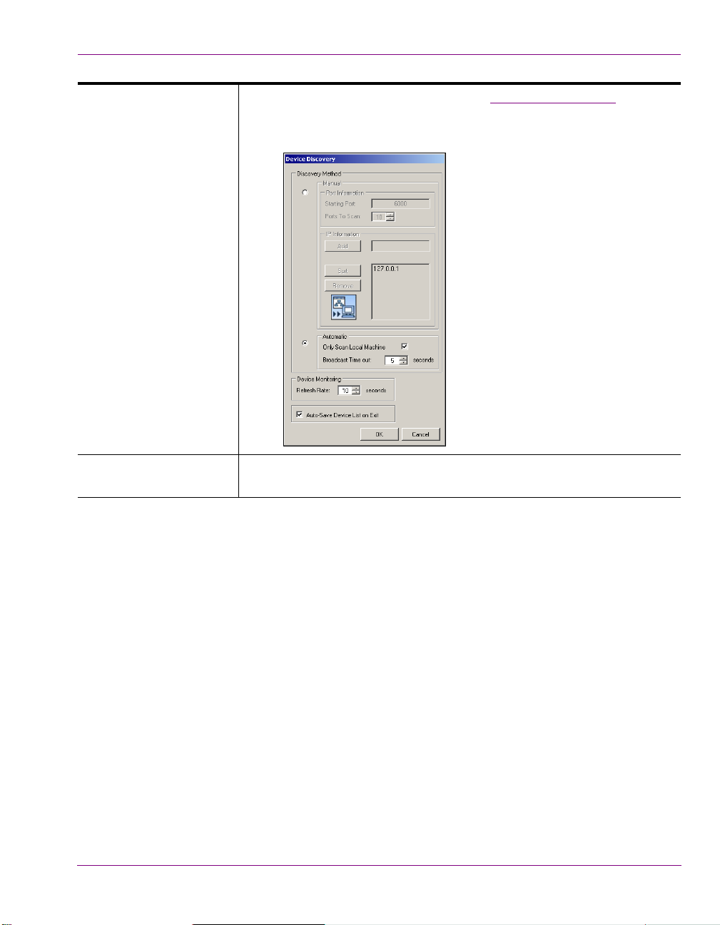
Dashboard - Intuition XG’s Local Configuration Software
TOOLS MENU SETTINGS > DEVICE DISCOVERY: Opens the Device Discovery Tool, which is
used to set the method that will be used to detect available devices, whether
they are local or remote (on the network).
ELP MENU Opens the ABOUT XG DASHBOARD dialog box, which displays the
H
Dashboard product information, including the version number.
Intuition XG Configuration Guide 5-7
Page 71
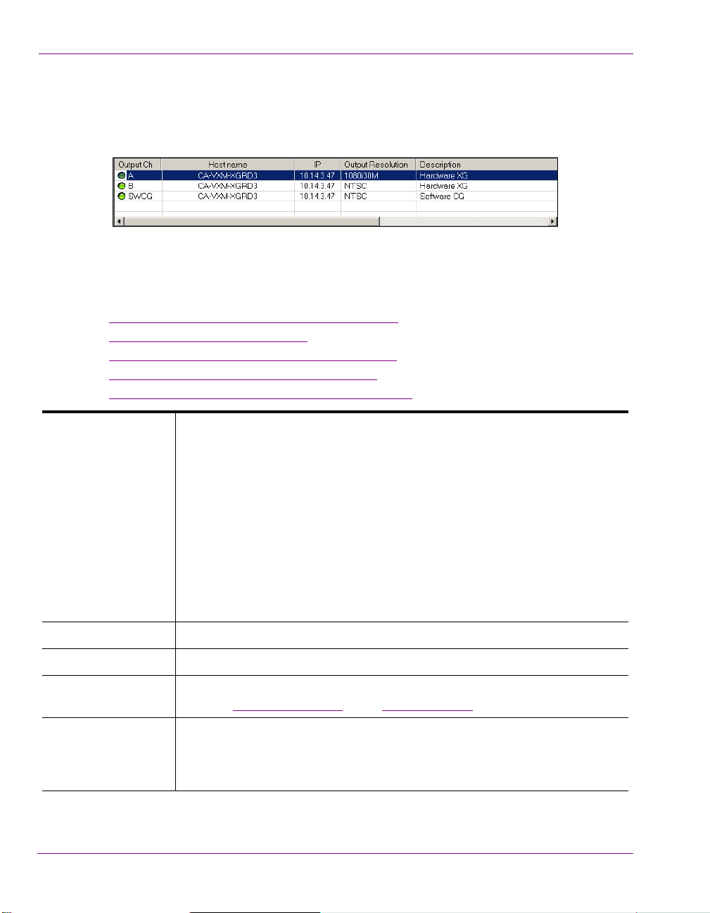
Dashboard - Intuition XG’s Local Configuration Software
Device List
The Device List identifies the Vertigo devices that were found on the host machine (local)
and/or on the network when a device discovery search is performed.
Depending upon which S
Profile page or the configuration pages for the selected device.
The following table provides a description for each of the columns in the Device List and the
topics listed below describe the tasks that you can perform using the Device List.
Loading and refreshing the device list” on page 5-9
• “
• “Saving the device list” on page 5-9
• “Restarting a device in the device list” on page 5-10
• “Monitoring the status of a device” on page 5-10
• “Removing a device from the device list” on page 5-10
OUTPUT CHANNEL Displays the name of the output channel for the Vertigo device. Typically, this is
OST NAME Displays the name of the host computer.
H
ETTINGS MODE is selected, Dashboard displays either the Device
A or B.
Note: If the device is a Vertigo software CG, this field always displays “SWCG”
as the output channel.
A green or red light is displayed next to the output channel name, which
indicates the state of the device.
The green light indicates that the device is active, connected to Dashboard, and
ready to accept commands.
The red light indicates that the device is not active and no connection has been
established by Dashboard. Therefore, you need to start the device and connect
it to Dashboard through the host computer or the network.
IP Displays the IP address of the device.
OUTPUT RESOLUTION Displays the setting of the output rendering resolution as specified on the
device’s Device Profile page
ESCRIPTION Displays whether the device is a Software CG (Software-based rendering and
D
preview application) or a hardware XG (hardware-based renderer and
production device). Also, displays connection error messages (e.g. Failed to
Open Socket).
5-8 Intuition XG Configuration Guide
or the Resolution page.
Page 72

Dashboard - Intuition XG’s Local Configuration Software
Loading and refreshing the device list
The mechanism used to find and list devices on Dashboard ‘s Device List is a tool called
the Device Discovery Tool
to select between two methods of searching for Vertigo devices: automatic or manual.
Upon starting, Dashboard automatically begins a device discovery to locate the available
Vertigo devices and then lists them on the Dashboard’s Device List.
You can set the method used during the device discovery anytime, by accessing the Device
Discovery tool from Dashboard’s T
Use the Device menu’s R
update the device list at anytime. This action starts a device discovery that scans the local
machine and/or network and updates the status of the devices already listed and adds any
newly found devices.
Devices that are actively connected and ready to be used with Dashboard are indicated in
the Device List with a green light next to their name, while inactive devices have a red light.
When a device discovery is performed and the list is refreshed, the status of the listed
devices is also updated. An inactive device means that it is not in communication with
Dashboard, perhaps because the device is turned off, it has crashed, or the network is
down. If the device has crashed, you can restart it using Dashboard’s R
command (see “Restarting a device in the device list” on page 5-10). When the device is
active again, performing a refresh of the device list will return its status to a green light.
. As described on page 5-11, the Device Discovery tool allows you
OOLS>SETTINGS menu (see page 5-11 for instructions).
EFRESH DEVICE LIST command, or the REFRESH button , to
ESTART DEVICE
Saving the device list
Upon starting, Dashboard automatically begins a device discovery to locate the available
Vertigo devices and then lists them on the Dashboard’s Device List. This initial device list
can be saved, so that the next time Dashboard performs a device discovery (refresh), it only
has to update the status of the listed devices rather than searching for them again.
Use the File menu’s SAVE DEVICE LIST command, or the SAVE button, to save the device
list. If you do not save the device list before exiting Dashboard, the application asks you if
you would like to save the device list before exiting. This prompt only happens the first time
you exit Dashboard after installation.
As an alternative to manually saving the device list, you can use the Device Discovery tool’s
UTO-SAVE DEVICE LIST ON EXIT parameter to automatically save the device list when you
A
exit the Dashboard application.
Intuition XG Configuration Guide 5-9
Page 73

Dashboard - Intuition XG’s Local Configuration Software
Restarting a device in the device list
During configuration, there are some device parameters that require that the Vertigo device
to be restarted before the new settings can take effect. When these settings are changed,
Dashboard automatically prompts you with a dialog box asking if you want to restart the
device immediately. If you would rather restart the device at a later time, decline
Dashboard’s request and use the Device menu’s R
ready to restart the device.
Another use for the Restart Device command is to re-activate a device from the Device List
that has become inactive (red light) because the device crashed. The R
command performs a remote restart of the device, which may resolve the issue and return
the device to an active state (green light) after performing a refresh of the device list.
Monitoring the status of a device
The status of a Vertigo device is reported in the Device List by a green (active) or red
(inactive) light next to its name. You can monitor the status of a device by activating the
Device menu’s MONITOR DEVICE STATUS command, which uses the REFRESH RATE setting
on the Device Discovery tool to determine at what frequency to update the device’s status
on the device list.
To monitor the status of a Vertigo device listed in the Dashboard Device List:
1. Select the device in the Device List.
2. Launch the Device Discover tool by selecting T
3. Set the Device Monitoring’s Refresh Rate parameter to the desired frequency interval.
For example, a setting of 10, checks the status every 10 seconds.
4. Click OK.
5. Select the M
ONITOR DEVICE STATUS command in the DEVICE menu.
ESTART DEVICE command when you are
ESTART DEVICE
OOLS >SETTINGS >DEVICE DISCOVERY.
Removing a device from the device list
If the device list has previously been saved, it will list all of the Vertigo devices found and
updated from the previous device discovery, including Vertigo devices that are active,
inactive, local, and/or networked.
There may be times when you want to limit the devices displayed in the device list to a
particular few. If this is the case, you can tailor the device list by removing any unwanted
devices from the device list.
To remove a device from the device list:
1. Right-click on the device in the device list that you want to remove.
2. Select the R
5-10 Intuition XG Configuration Guide
EMOVE DEVICE command.
Page 74
Device Discovery Tool
The Dashboard Device Discovery tool allows you to set the method to be used to detect the
Vertigo devices that are local to your machine or on your network. Once the devices are
located, Dashboard lists them on the Device List, which allows you to view and edit the
device’s settings.
The Device Discovery tool is accessed by selecting Dashboard’s TOOLS >SETTINGS >
EVICE DISCOVERY menu command (figure 5-4).
D
Dashboard - Intuition XG’s Local Configuration Software
Figure 5-4. Launching the Device Discovery Tool
One of the first things that Dashboard does on start up is use the Device Discovery tool to
perform a device discovery. A device discovery performs a search of your local machine
and/or your network for all of the active Vertigo devices that are able to connect to
Dashboard and then lists them on Dashboard’s Device List
Device List displays the Device Profile page or the Device configuration pages depending
upon the Settings Mode.
The following table provides a description for each of the fields on the Device Discovery
dialog box and the topics listed below describe the tasks that two methods that you can use
to perform the device discovery.
Performing a Manual Device Discovery” on page 5-13
• “
• “Performing an Automatic Device Discovery” on page 5-14
Intuition XG Configuration Guide 5-11
. Selecting a device from the
Page 75

Dashboard - Intuition XG’s Local Configuration Software
MANUAL PORT INFORMATION
• STARTI NG PORT: Specifies the port number to use as the starting point
for searching for devices.
ORTS TO SCAN: Specifies the number of ports to scan starting at the
• P
port number specified in the Starting Port.
IP INFORMATION
Displays a list of IP addresses to scan to detect Vertigo devices. The IP
address is that of the machine that the device is running on. You can get this
IP address either by typing IPConfig on the command prompt, or by using
the IP address listed on the Vertigo device’s software’s dialog box.
DD: Enter a specific IP address that you suspect the device to be
• A
using.
ORT: Arranges the IP addresses added to the IP information list in
• S
descending numerical order.
EMOVE: Removes the selected IP address from the IP Information list.
• R
UTOMATIC The device discovery’s automatic mode performs a thorough search for all
A
of the Vertigo devices on your local machine or on your network.
NLY SCAN LOCAL MACHINE: Rather than searching for all of the
• O
Vertigo devices on your network, this setting limits the search to finding
all the Vertigo devices connected/on your local machine.
IME OUT: Sets a time limit at which to stop the search for devices. The
• T
default value is 5 seconds.
D
EVICE MONITORING REFRESH RATE: Sets the frequency (in seconds) at which to poll the devices
to see if they are active or inactive. The default value is 10 seconds. See
“Monitoring the status of a device” on page 5-10 for more information.
S
AVE DEVICE LIST ON
XIT
E
The Save Device List on Exit automatically saves the device list when you
exit Dashboard. By default this parameter is not enabled. See “
Saving the
device list” on page 5-9 for more information.
5-12 Intuition XG Configuration Guide
Page 76

Dashboard - Intuition XG’s Local Configuration Software
Performing a Manual Device Discovery
The Device Discovery’s manual mode allows you to focus your device search by limiting the
search to particular port and IP limits. The search begins scanning for devices from the port
number specified and then each sequential port up as specified by the Ports to Scan value.
It is recommended that you use the manual method if you are wanting to configure a
particular Vertigo device and you know roughly, or even exactly, where the device is located
on the network using its port and IP address information.
To perform a manual device discovery:
1. Open the Device Discovery tool by selecting T
2. Set the D
a. Select the M
EVICE DISCOVERY METHOD in the device discovery tool.
ANUAL Discovery Method.
b. Set the STARTING PORT parameter by typing in the port number that you suspect
the device to be using for the Vertigo device.
c. Set the P
ORTS TO SCAN parameter.
d. Verify that the appropriate IP address appears in the IP Information list (see IP
INFORMATION in the table above).
OOLS >SETTINGS >DEVICE DISCOVERY.
If the desired IP address does not exist, type the IP address digits in the A
box and click the ADD button. Be sure to pay close attention to the dot separators
when typing the IP Address.
e. Click OK.
3. Start the device discovery process by clicking the R
EFRESH button .
Dashboard will start scanning the specified IP addresses and ports for any available
Vertigo devices. Dashboard then automatically updates the Device List.
DD text
Intuition XG Configuration Guide 5-13
Page 77

Dashboard - Intuition XG’s Local Configuration Software
Performing an Automatic Device Discovery
The automatic method of performing a device discovery provides you with the options of
scanning only your local machine for an active Vertigo device, or to scan the network within
a specified time out period.
To perform an automatic device discovery:
1. Open the Device Discovery tool.
OOLS >SETTINGS >DEVICE DISCOVERY
T
2. Set the Device Discovery method in the device discovery tool.
a. Select the A
UTOMATIC Discovery Method.
b. Disable the ONLY SCAN LOCAL MACHINE parameter.
c. Click OK.
3. Refresh the Device List by clicking the R
EFRESH button .
Dashboard will start scanning the network and the local machine for any available
Vertigo devices. Dashboard then automatically updates the Device List. Select the
desired device from the Device List. If the desired device has a green light in the Output
Channel column, continue to the next phase in the configuration procedure.
If, however, the desired device is still not listed on the Device List, or if the device is
listed, but has a red light in the Output Channel column, you will have to verify the
status of the device (on/off), as well as the status of the network.
5-14 Intuition XG Configuration Guide
Page 78

Device Profile page
The Device Profile page appears below Dashboard’s Device List when the SETTINGS M ODE
is set to S
page provides a brief summary of some of the device and system’s settings that may be
relevant when operating or troubleshooting the system.
The following table describes each of the fields that are displayed on the Device Profile
page for Vertigo devices:
IMPLE and a device is selected from the Device List (figure 5-5). The Device Profile
Figure 5-5. Dashboard’s Device Profile page
Dashboard - Intuition XG’s Local Configuration Software
ENERAL • DEVICE NAME: The name given by the last connecting application. Such as
G
Xplay or Xstudio.
EVICE TYPE: Displays the Vertigo device type, either HARDWARE XG or
• D
SOFTWARE CG.
V
ERSION • APPLICATION VERSION: Displays the software version of Vertigo device.
• DSX.
UTILS VERSION: Displays the version of the driver used inside the Vertigo
device.
G
RAPHICS • CARD TYPE: Identifies the type of graphics card used by the Vertigo device.
This information is useful when troubleshooting the Vertigo device as some
functionality might depend upon the type of graphics card used.
EMORY USE: Displays the total amount of memory being used by the
• M
graphics card, including host and onboard.
P
ORTS • APPLICATION PORT: Displays the communication port used between the
Dashboard application and the selected Vertigo device.
OMMAND PORT: The communications port used by the Vertigo device for
• C
command and control by applications, such as Xstudio or Xplay. To edit this
setting, select the Display Settings Tab and edit the C
OMMAND PORT field.
Intuition XG Configuration Guide 5-15
Page 79

Dashboard - Intuition XG’s Local Configuration Software
OUTPUT • RESOLUTION: Allows you to set the resolution format that is used for
processing within the Vertigo device. You can set the output Resolution either
in this field or in the O
PAGE (page 5-21).
HANNEL: Specifies the output channel used by the Vertigo device. The
• C
UTPUTS RESOLUTION field on the ADVANCED>RESOLUTION
available output channels are determined by the installed hardware. You can
set the Output Channel either in this field or in the OUTPUTS CHANNELS field on
ARDWARE SETTINGS>VIDEO PAGE (page 5-34).
the H
ODE The Mode setting specifies the processing mode of the Vertigo device.
M
PSTREAM: When UpStream mode is enabled, the device is configured as
• U
follows:
1. There is no video input.
2. The device outputs both a fill and key signal.
3. The Watch Dog is enabled.
4. The Watch Dog key signal is transparent.
OWNSTREAM: When in Downstream mode is enabled, the device is
• D
configured as follows:
1. The device processes video input and the input channel
matches the output channel.
2. The device outputs only a fill signal.
3. The Watch Dog is enabled.
4. The Watch Dog key signal is transparent.
DVANCED: When this read-only field is enabled, it indicates that the device
• A
has been configured through the Advanced setting mode so that its settings
do not match the Upstream of Downstream settings.
G
ENLOCK This setting controls the sync of the Vertigo device. It is a simplified view of the
ADVANCE>HARDWARE SETTINGS>GENLOCK PAGE.
OURCE: Specifies the source of the Genlock signal. Choose from the
• S
following settings: I
NTERNAL, BLACKBURST, VIDEOIN A, or VIDEOIN B (assuming
the hardware contains inputs).
ESOLUTION: Specifies the resolution of the Genlock signal. The Resolution
• R
can also be set on the H
TATUS: Reports the status of the Genlock signal (i.e. the Intuition XG has
• S
locked onto the signal). The Status can also be set on the H
ETTINGS>GENLOCK page (page 5-11).
S
ARDWARE SETTINGS>GENLOCK page (page 5-11).
ARDWARE
5-16 Intuition XG Configuration Guide
Page 80

Dashboard - Intuition XG’s Local Configuration Software
NOTE
Device Settings tabs and configuration pages
Selecting ADVANCED from the SETTINGS MODE drop-down list produces a series of eight (8) tabs
that display thematic pages of parameters and settings that allow you to configure the selected
device (figure 5-6).
Figure 5-6. Selecting the Advanced Settings Mode exposes the device’s configuration pages
The seventh page is dynamic, meaning that when the selected device is a hardware XG,
the seventh tab is labelled HARDWARE SETTINGS; however when the selected device is a
software CG the seventh tab is labelled AUDIO & VIDEO.
The following topics describes each of the parameters and settings on the device’s
configuration pages:
Device settings buttons” on page 5-18
• “
• “General page” on page 5-19
• “Resolution page” on page 5-21
• “Live Window page” on page 5-23
• “Clips page” on page 5-25
• “3D Engine page” on page 5-27
• “Logging page” on page 5-29
• “Hardware Settings > Genlock page” on page 5-31
• “Hardware Settings > Video page” on page 5-34
• “Hardware Settings > Audio page” on page 5-36
• “Hardware Settings > Ancillary page” on page 5-38
• “Hardware Settings > Watch Dog page” on page 5-41
• “Licensing page” on page 5-42
Intuition XG Configuration Guide 5-17
Page 81

Dashboard - Intuition XG’s Local Configuration Software
buttons
Device settings
Device settings buttons
When Dashboard is in ADVANCED Settings Mode, selecting the tabs exposes the device’s
configuration pages, which allows you to edit the device’s current settings. Once you have
made the desired changes to the settings, you must apply the changes to the device by
selecting the A
will request that the device be restarted (see R
PPLY CHANGES button. Note that for some changes to take effect, Dashboard
ESTART DEVICE on page 5-6).
Figure 5-7. Device Settings buttons
You can retract the changes that you make to the device settings by performing an UNDO,
as long as you haven’t already applied the changes. If you have made unwanted changes,
you can revert to the device’s default settings by pressing the R
ESTORE FACTORY DEFAULTS
button.
The following table summarizes the function of the three (3) buttons in the lower portion of
Dashboard’s device configuration pages.
R
ESTORE FACTORY
EFAULTS
D
A
PPLY CHANGES Applies all of the new settings from the page to the selected device.
U
NDO CHANGES Reinstates the page’s device settings back to what they were at the last
Resets all of the parameter settings to Dashboard default settings.
A
PPLY CHANGES action.
5-18 Intuition XG Configuration Guide
Page 82

General page
Selecting the GENERAL tab in Advanced Settings mode, opens the General settings page
(figure 5-8
device parameters, including storage settings and communication settings between the
Vertigo devices, Xplay, and/or the broadcast monitor.
). This configuration page provides you access to a series of miscellaneous
Figure 5-8. The General settings tab and page on the Dashboard Window
Dashboard - Intuition XG’s Local Configuration Software
SSETS PUBLISH PATH: Identifies the directory location where assets are stored on the
A
Vertigo device, or on the host computer (software CG). The default directory
paths for the Vertigo hardware devices is F\:Scene\, while the default
directory path for the Vertigo Software CG is C\:Scene\.
Assets are automatically placed within appropriate subfolders by the publish
agent. For example, images are stored in the Image subfolder.
TCP/IP C
STATISTIC S ENABLED: Displays the frame rate, video card, and memory use on the output
Intuition XG Configuration Guide 5-19
OMMAND PORTS: Sets the communications port used by the Vertigo devices
and Vertigo software CG for command and control between applications
(i.e. Intuition XG and Xplay). This port must be open and 2-way unblocked on
the Vertigo device’s subnet.
display for debugging purposes.
EXTRA INFO: Displays timing information (Dx9, DSX, Readback) on the
Intuition XG’s output display for debugging purposes. Timing values are
displayed in milliseconds for each thread
Page 83

Dashboard - Intuition XG’s Local Configuration Software
AUTOMATION MODE: Determines the timestamping mechanism used for commands
between the Vertigo devices and Xplay.
ISABLED: When selected the timestamp of the command will be ignored
• D
and the command is executed immediately.
YSTEM COUNTER: High performance counter issued to reference the
• S
time of the command.
YSTEM CLOCK: Sets the format of the timestamps, which is timecode-
• S
based (Hour: Minute: Seconds: Frames).
DEAD BAND: Sets the dead band zone for the time stamping of commands. If
the difference in timestamps between multiple commands is less than the
dead band, the earlier timestamp will be use for all commands.
P
REROLL: Sets the preroll time by which all timestamps are adjusted. The
default value for this setting is 10 frames.
PREROLL MARGIN: When the Vertigo devices receive automation commands,
they are usually timestamped. The devices add the preroll time as an offset to
these timestamps. The preroll margins is an additional offset added. The
preroll setting is an integer allowing only whole frames. The preroll margin
allows fractional values. The default value for this setting is 0.25 frames.
ENDER PATHS IMAGES: Specifies the directory path of where the image file will be saved to
R
when the S
C
LIPS: Specifies the directory path of where the image file will be saved to
when the R
NAPSHOT command is used in Xbuilder.
ENDER TO DISK command is used in Xbuilder.
EL ANIMATIONS CACHE SIZE: Sets the number of cel animations that are cached in system
C
memory after they are no longer referenced by a loaded scene.
The default is 250. Increasing the cache size setting will unnecessarily slow
down performance and occupy memory space.
AX SIZE: Specifies the maximum size of a cel animation that Intuition XG will
M
accept. Cel animations that are larger are rejected. The default is 250 MB.
D
EVICE OUTPUT FILL: Only the fill signal will be transmitted to the output monitor.
FILL AND KEY: The fill and key signals will be transmitted to the output
monitor/device. This setting is the default for Intuition XG devices.
I
NITIAL KEYER STATE Sets the initial state of the Vertigo device’s internal virtual keyer list.
O
N: Sets the Vertigo device’s keyer to an active state. This is the default
setting.
OFF: Sets the Vertigo device’s keyer to an inactive state.
R
OLL UPDATE INTERVAL Determines if the vertical movement interval of a crawl is based on a FIELD or
F
RAME.
P
ASSWORD A simple security feature that allows you to set a password so that other users
cannot change the device settings.
5-20 Intuition XG Configuration Guide
Page 84
Dashboard - Intuition XG’s Local Configuration Software
Resolution page
The Resolution page (figure 5-9) provides access to the device parameters that set the
input, rendering, and output resolution of the video data.
Figure 5-9. The Resolution tab and page on the Dashboard window
I
NPUT RESOLUTION This parameter is only available to Vertigo hardware devices (not the
software CG).
The Input Resolution parameter allows you to select the input resolution of
the video data prior to processing by Vertigo device. Select a resolution
format from the drop-down list of preset formats that are compatible with the
rendering resolution.
• NTSC: Sets the rendering resolution to NTSC format
(720 x 486) Rate: 29.97
• NTSC_W
NTSC-Wide format (800 x 486) Rate: 29.97
• PAL : Sets the rendering resolution to PAL format
(720 x 576) Rate: 25
• PAL _W
format (800 x 576) Rate: 25
• 720
(1280 x 720) Rate: 60
• 720
format (1280 x 720) Rate: 59.97
• 1080
(1920 x 1080) Rate: 25
• 1080
format (1920 x 1080) Rate: 29.97
• 1080
(1920 x 1080) Rate: 30
• 1080
format (1920 x 1080) Rate: 23.98
IDE: Sets the rendering resolution to
IDE: Sets the rendering resolution to PAL-Wide
P60: Sets the rendering resolution to 720p60 format
P60M: Sets the rendering resolution to 720p60M
I25: Sets the rendering resolution to 1080i25 format
I30M: Sets the rendering resolution to 1080i30M
I30:Sets the rendering resolution to 1080i30 format
I24M: Sets the rendering resolution to 1080i24m
Intuition XG Configuration Guide 5-21
Page 85

Dashboard - Intuition XG’s Local Configuration Software
INPUT RESOLUTION -
CONTINUED
• 1080P24:Sets the rendering resolution to1080p24 format
(1920 x 1080) Rate: 24
• 1080
P25:Sets the rendering resolution to 1080p25 format
(1920 x 1080) Rate: 25
• 1080
P30M: Sets the rendering resolution to 1080p30m
format (1920 x 1080) Rate: 29.97
• 1080
P30:Sets the rendering resolution to 1080p30 format
(1920 x 1080) Rate: 30
• CUSTOM: Sets the rendering resolution to the resolution
values set in the rendering resolution width, height, and
rate fields. This setting is only available to Software CG
devices.
UTPUT RESOLUTION The Output Resolution parameter allows you to specify the output resolution
O
of the Vertigo devices.
WIDTH, HEIGHT, & RATE: Displays the width (horizontal lines), height (vertical
lines), and frame rate of the output resolution selected. These fields are
read-only, except when CUSTOM is selected as the Output Resolution.
Note, however, that the Custom setting is only available to Software CG
devices. The width, height, and rate rendering values for Intuition XG
devices are determined by the resolution format selected.
SCENE SCALING This allows the Vertigo devices to account for the fact that sometime the
resolution of the scene being rendered does not match the resolution that
the device is rendering at.
AUTOSCALE: Specifies if the scale is automatically calculated by comparing
the scene resolution with the output resolution or if the user can manually
enter scaling values.
IDTH & HEIGHT: Displays the scaling factor that will be applied to width and
W
height of the scene during rendering.
CENE RESOLUTION: Specifies the resolution of the scenes to be loaded.
S
W
IDTH & HEIGHT: Show the width and height of the scene resolution
selected. If the resolution is set to C
USTOM, then the width and height can be
entered manually.
5-22 Intuition XG Configuration Guide
Page 86

Live Window page
In addition to the output display, the Live Window page provides you with parameters for
enabling an additional display of a window on the computer monitor (Live Window) that
shows the output of the Vertigo device.
Figure 5-10. The Live Window tab and page on the Dashboard window
Dashboard - Intuition XG’s Local Configuration Software
NABLED Enables the display of the Live Window. In the case of the Vertigo CG, the
E
Live Window is the only method of seeing the output.
M
ODE Selecting ENABLED, activates the following parameters allowing you to set
the size and positioning of the Live Window.
FULL SCREEN: Sets the Live Window to occupy the entire display area, and
therefore, replaces the output display.
INDOWED: Sets the Live Window to display in a separate window.
W
Selecting this setting activates the Window Behavior parameters that allow
you to set the positioning and size of the Live Window.
Intuition XG Configuration Guide 5-23
Page 87

Dashboard - Intuition XG’s Local Configuration Software
Mode - continued WINDOW BEHAVIOR: The following parameters are activated when
Windowed is selected, and they allow you to set the positioning and size of
the Live Window.
LWAYS ON TOP: Specifies whether the Live Windows is always the top
• A
window.
RAMED: Enables a frame around the Live Window.
• F
APTION: Allows the override of the default Live Window caption (title).
• C
CALE: Specifies a scaling factor for the width and height of the live
• S
window. Choose from 1.0, 0.5, or 0.25 values.
• X: Specifies the vertical screen coordinate of the top left corner of the
Live Window. A value of zero (0) locates the window in the upper-most
corner of the screen.
• Y: Specifies the horizontal screen coordinate of the top left corner of the
Live Window. A value of zero (0) locates the window in the left-most
corner of the screen.
IDTH & HEIGHT: Displays the size of the Live Window by setting the
• W
vertical and horizontal dimensions in pixels. These are read-only fields
and match the values specified by the Output Resolution field on the
Resolution page
A
DAPTER ORDINAL Specifies which VGA display adapter to use for rendering. Note that
.
displaying the Live Window on the incorrect VGA display will unnecessarily
increase CPU usage.
5-24 Intuition XG Configuration Guide
Page 88

Clips page
The parameters on the Clips page allow you to set clip rendering characteristics.
Dashboard - Intuition XG’s Local Configuration Software
Figure 5-11. The Clips tab and page on the Dashboard window
R
ENDERER The following fields specifies which renderer will be used to produce and insert
the graphics and video clips for output.
VMR9: Specifies that the VMR9 (Video Mixing Renderer 9) will be used for clip
playback. This is the default renderer.
POOL SIZE: Only available when VMR9 is selected as the renderer. Pool Size
specifies the number of VMR9s that are preallocated at the start up of the
application. The default value of -1 disables the preallocation.
USTOM: Specifies that the Vertigo hardware device’s own video renderer will
C
be used for clip playback.
PIXEL SHADER: Only available when CUSTOM is selected as the renderer.
Selecting Pixel Shader allows pixel color conversion to be done on the Vertigo
device’s GPU. When Pixel Shader is not selected, pixel color conversion is
performed on the host computer.
DEINTERLACING The renderers processing format is interlaced, but all of the other functions are
performed in progressive.
ENABLED: The Vertigo device will deinterlace clips using the best method
available. This is the default setting.
FORCED SOFTWARE: The Vertigo device will use the Vertigo’s own deinterlacing
algorithm.
Intuition XG Configuration Guide 5-25
Page 89

Dashboard - Intuition XG’s Local Configuration Software
REFERENCE CLOCK AUTO: Specifies that the clip rendering will be clocked.
O
N: Specifies that the clock will always be used in clip rendering.
O
FF: Specifies that the clock will not be used in clip rendering.
F
ILE EXTENSIONS Specifies the extensions of video file formats that are supported. Although the
more commonly used formats are already listed in this field, you can also add
additional format extensions to the list.
MAGE EXTENSIONS Specifies the extensions of image file formats that are supported. Although the
I
more commonly used formats are already listed in this field, you can also add
additional format extensions to the list.
MPEG2HARDWARE ACCELERATION: When selected, Mpeg-2 decoding is performed
using the Vertigo device’s GPU. When this parameter is not selected, Mpeg-2
decoding is performed by the CPU. This parameter is unchecked in its default
state.
LAYBACK The following parameters are only displayed on the Clips page when a Vertigo
P
device is selected in the device list.
CLIP FRAME SYNCH: Forces clips to remain synchronized with the start of
frames.
KEEP STRICT AUDIO RATE: Only allows 48 kHz audio to be used in clip playback.
A
NIMATION CODEC PRELOAD MAXIMUM: Specifies the maximum size (MB) of a file that will be
preloaded into system memory. All files smaller will be loaded into system
memory for playback and all files larger will be streamed off disk. The valid
range is 50 to 500.
ULTI-THREADED DECOMPRESSION: Determines if the decompression of the
M
Vertigo animation clips is multi-threaded or single-threaded.
ALLOW MIP MAPPING: When enabled, the Vertigo XG device performs mip
mapping when rendering animation (VAF) files.
A
UDIO EXTENSIONS Specifies the extensions of audio formats that are supported. Although the more
commonly used formats are already listed in this field, you can also add
additional audio format extensions to the list. Please read “The Intuition XG
provides advanced branding capabilities to master control switchers” on page
1-7 before editing the list.
B
UFFERING USE EXTRA BUFFERS: When selected, extra buffers are used between the clip
engine and the rendering engine (output engine). This parameter is selected in
its default state.
5-26 Intuition XG Configuration Guide
Page 90
3D Engine page
The 3D Engine page provides access to parameters that allow you to set some parameters
that affect the way in which 3D graphics are rendered and output by the Vertigo hardware
devices. The following table describes each of the parameters on the 3D Engine page.
Figure 5-12. The 3D Engine tab and page on the Dashboard window
Dashboard - Intuition XG’s Local Configuration Software
YE DISTANCE The Eye Distance parameters set the three dimensional positioning by
E
defining the spatial perspective/location of how far the object is from the
camera (close, far).
IEW PLANE HEIGHT FACTOR: Sets the field of view of the camera.
V
N
EAR VIEW-PLANE FACTOR: Sets the distance from the camera in world
space units. Anything closer to the camera will be clipped.
AR VIEW-PLANE FACTOR: Sets the distance from the camera in world space
F
units. Anything farther from the camera will be clipped.
IP MAPPING Mip mapping allows for a higher level of layering detail by internally creating
M
collections of bitmap images to accompany a main texture. This is intended
to increase rendering speed of 3D graphics, and improves the digital video
effects (DVE) quality.
NABLED: When selected, the Vertigo hardware device performs mip
E
mapping when rendering 3D graphics.
LOAD BIAS: When Enabled is selected for Mip Mapping, the Load Bias
parameter allows you to set the level of detail bias for mipmapping by
adjusting the slider between -3 and +3. Values below 0 result in less blurred
mip-level choice. The default value is -0.50.
Intuition XG Configuration Guide 5-27
Page 91

Dashboard - Intuition XG’s Local Configuration Software
MODE • LAND SCAPE: The default orientation of the Vertigo device’s output.
ORTRAIT: Rotates the Vertigo device’s entire output by 90 degrees
• P
clockwise.
NVERTED PORTRAIT: Rotates the Vertigo device’s entire output by 90
• I
degrees counter-clockwise.
G
ENERAL FORCE POWER OF 2 TEXTURES: Textures are typically square and must have
side lengths equal to a power of 2. Some graphics cards do not adequately
support non-power of two textures, so you can select this parameter to force
the textures to conform to the power of 2 requirement.
ENABLE CULLING: Prevents elements of 3D graphics that are non-visible
from the rendering process, thereby making the rendering process more
efficient.
NABLE ANTIALIASING: Enables antialiasing rendering in 3D. Reduces 3D
E
edge artifacts.
SWAP COPY: This parameter is only available to the Vertigo software CG and
only when the Live Window is full screen. Swap Copy makes overlay
graphics slower by allowing buffer swaps to be performed as a copy from
back to front, rather than having the back and front exchanged. These
conditions allow some video cards to perform better. This parameter is not
selected by default.
ACK BUFFER COUNT: This parameter is only available to the Vertigo
B
software CG and it is used with the Swap Copy parameter. This parameter
specifies the number of back buffers to use in the Swap Copy. The default
is set to 2.
NABLE INTERLACED RENDERING: Determines if the window is the height of
E
a field or the height of a frame (unchecked). This setting has no effect if the
output resolution is progressive, since there are only frame, no fields, in
progressive.
5-28 Intuition XG Configuration Guide
Page 92

Logging page
The logging page allows you to set parameters to create log files that record the status of
events while the Vertigo devices are running. The log files can then be use to investigate
device behavior and debug.
Dashboard - Intuition XG’s Local Configuration Software
Figure 5-13. The Logging tab and page on the Dashboard window
ILENAME The name of the log file. The name cannot be changed, however, if multiple
F
log files are created, then an underscore, date, and time are appended to
the file name. The default name is “VertigoXG”.
F
ILE SIZE Sets the maximum memory size for each log file created per run. The default
value is 6 MB.
F
ILE COUNT Sets the maximum number of log files to be created per run. The default
value is 20.
L
OG LEVEL Sets the severity categories that will be reported to the log file.
RROR: An error of some type has occurred and this log category will
• E
likely indicate the source of a problem.
ARN: Be aware that something unexpected has happened, like
• W
unsuccessful operations that may indicate a problem.
NFO: Logs important events that occur during normal conditions, which
• I
allows you to trace what and when the applications are doing.
Intuition XG Configuration Guide 5-29
Page 93

Dashboard - Intuition XG’s Local Configuration Software
DEBUG CATEGORY LIST Sets the categories that will be reported to the log file.
ENERAL: General information.
• G
• DIRECT X: Information pertaining Direct and 3D rendering.
IRECT SHOW: Information about Direct Show, which is used to play
• D
clips and audio files.
SX: Information about the video I/O device.
• D
CP: Information about network communication.
• T
• CALLBACK: Information about callback replies sent to applications, like
Xplay or Xstudio.
ILE: Information about attempts to access files on the disk.
• F
ONTRENDERER: Information about text rendering.
• F
NIMATIONS: Information about animations.
• A
• LICENSING: Information about licensing.
ENDERTODISK: Information about the Render to Disk functionality.
• R
CLEAR ALL button: Allows you to quickly de-select all of the selected debug
categories.
5-30 Intuition XG Configuration Guide
Page 94

Dashboard - Intuition XG’s Local Configuration Software
Hardware Settings > Genlock page
The Genlock page is a sub-page of the Hardware Settings tab, which is only visible when a
Vertigo hardware device is selected in the Dashboard’s device list. The Genlock page (figure
) exposes parameters that allow you to set the Vertigo device’s genlock reference signal
5-14
that synchronizes the phase timing eliminating video jitter.
The source of the Vertigo device’s genlock reference signal can be set to come from one of
four sources: internal, blackburst, SDI Video In A, or SDI Video In B.
Figure 5-14. The Genlock Page within Dashboard’s Hardware Settings
OURCE The source of the Vertigo device’s genlock reference signal can come from
S
one of four sources:
NTERNAL: Genlock to the video card, which generates its own
• I
synchronization clock
LACKBURST: The blackburst signal contains the vertical, horizontal,
• B
frame, color synchronization, and field 1 reference, without any video
data.
• SDI V
IDEO A: The SDI video A input signal inherently carries a
reference signal and therefore it can be used as a genlock signal.
• SDI V
IDEO B: The SDI video B input signal inherently carries a
reference signal and therefore it can be used as a genlock signal.
R
ESOLUTION Specifies the resolution of the genlock signal. In cases where two instances
of the Vertigo devices are running simultaneously with different resolutions,
both instances should specify the lower resolution for genlock.
Select one of the following resolution formats from the drop-down list:
• NTSC: Sets the rendering resolution to NTSC format (720 x 486)
Intuition XG Configuration Guide 5-31
Page 95

Dashboard - Intuition XG’s Local Configuration Software
RESOLUTION - CONTINUED • NTSC_WIDE: Sets the rendering resolution to NTSC-Wide format
(800 x 486)
• PAL: Sets the rendering resolution to PAL format (720 x 576)
• PAL_W
IDE: Sets the rendering resolution to PAL-Wide format
(800 x 576)
• 720
P60: Sets the rendering resolution to 720p60 format
(1280 x 720)
• 720
P60M: Sets the rendering resolution to 720p60M format
(1280 x 720)
• 1080
I25: Sets the rendering resolution to 1080i25 format
(1920 x 1080)
• 1080
I30M: Sets the rendering resolution to 1080i30M format
(1920 x 1080)
• 1080
I30: Sets the rendering resolution to 1080i30 format
(1920 x 1080)
• 1080
I24M: Sets the rendering resolution to 1080i24m format
(1920 x 1080)
• 1080
P24: Sets the rendering resolution to 1080p24 format
(1920 x 1080)
• 1080
P25: Sets the rendering resolution to 1080p25 format
(1920 x 1080)
• 1080
P30M: Sets the rendering resolution to 1080p30m format
(1920 x 1080)
• 1080
P30: Sets the rendering resolution to 1080p30 format
(1920 x 1080)
B
IT COUNT Specifies the bit depth of the genlock signal. Choose either 8 (default) or 10
from the drop-down list.
S
TATUS & REFRESH
button
Identifies the current state of the Genlock signal source that is selected in
the SOURCE parameter.
OCKED: The connection is established and the on-board Genlock is
• L
sending a clocking signal to the Genlock source specified in the Source
parameter.
REE RUNNING: No signal is coming in on the selected Genlock source,
• F
or the specified signal formats are not the same. For example, if the
resolution setting on the Genlock page does not match the resolution
formats specified on the Resolution page.
ELOCKING: In the process of locking. Note that if continuously in this
• R
state, the Genlock signal might not be stable and it needs to be
checked.
5-32 Intuition XG Configuration Guide
Page 96

Dashboard - Intuition XG’s Local Configuration Software
STATUS & REFRESH
button - Continued
• UNKNOWN (UPDATE THE XG SOFTWARE): This message appears when
the version of the Vertigo software that is being used is an earlier
version and does not support this feature. If this is the case, you need
to update the Vertigo software.
Click the R
EFRESH button to request an update of the Genlock status of the
source. Each time you select a new Genlock Source setting and apply the
change, the status message will be gray until you click the Refresh button
to update the status.
ORIZONTAL DELAY Adjusts the horizontal timing of the signal in nanoseconds.
H
V
ERTICAL DELAY Adjusts the vertical timing of the signal in lines.
Intuition XG Configuration Guide 5-33
Page 97

Dashboard - Intuition XG’s Local Configuration Software
Hardware Settings > Video page
The Video page is a sub-page of the Hardware Settings tab, which is only visible when a
Vertigo hardware device is selected in the Dashboard’s device list. The Video page (figure
) exposes parameters that allow you to set the Vertigo device’s video input/output
5-15
channels and video processing options.
Figure 5-15. The Video page within Dashboard’s Hardware Settings
NPUT CHANNELS Specifies the input channel of the hardware to use. Depending on the
I
hardware configuration of the machine, the possible values are blank, A, or
B.
When running a single instance of the Vertigo device, both sources can be
used. But when running two instances of the device simultaneously, they
must each use a different input channel. In the case where there are more
instances running than input channels, some will have to leave the setting
blank.
UTPUT CHANNELS Specifies the output channel of the hardware to use. Depending on the
O
hardware configuration of the machine, the possible values are A, B, C, or
D. When running multiple instances of the Vertigo device simultaneously,
each instance must specify a different output channel. This parameter can
also be set using the Output Channel field on the Device Profile page (page
5-15).
IT COUNT Specifies the bit depth of the signal. Choose either 8 or 10 (default) from the
B
drop-down list.
5-34 Intuition XG Configuration Guide
Page 98

Dashboard - Intuition XG’s Local Configuration Software
VIDEO MODE Specifies how the Vertigo hardware device passes through video.
ACKGROUND VIDEO ON: The Vertigo device will always display the
• B
video input as the back most layer, even without any scene loaded.
IDEO ON CLEAR: When the Vertigo device has nothing to render (no
• V
scenes have been loaded), it will display the video input.
LACK ON CLEAR: When the Vertigo device has nothing to render (no
• B
scenes have been loaded), it will render nothing, displaying black.
O
N BOARD COMPOSITOR Allows the off loading of certain color conversion routines from the CPU to
the video card. This feature is dependant on the correct firmware options
being installed on the hardware.
C
OMPRESS KEY SIGNAL When this setting is enabled, the key signal color space is compressed so
it does not fall into super black or super white. The full 10-bit color space is
from 0 – 1023. The key signal is compressed into the range 64 – 940.
Above 940 is super white and below 64 is super black.
C
LIP SUPER BLACK &
SUPER WHITE
Determines whether or not the VertigoXG allows the output to be in the
super black & super white range. The luminance range of a 10-bit SDI
signal is from 0 to 1023. A value below 64 is considered super black and a
value above 940 is considered super white. When this setting is enabled,
the VertigoXG will clip any pixels below 64 up to 64 and any pixels above
940 down to 940.
I/O BUFFERING Together these I/O buffering values determine the video delay of the
passthrough.
NPUT: The number of buffered (frames) used for video input.
• I
UTPUT: The number of buffers (fields) used for video output.
• O
ROCESSING Specifies if color conversion of video input is off-loaded from the CPU to the
YUV P
GPU.
• CPU: Use the CPU to do the conversion.
• GPU: Use the GPU to do the conversion. The GPU is not
recommended, however, for HD video.
• GPU-PS: Uses the pixel shader to do YUV to RGB conversion.
ILL DELAY • HORIZONTAL: The slider adjusts the horizontal (nanoseconds) timing of
F
the fill signal.
ERTICAL: The slider adjusts the vertical (lines) timing of the fill signal.
• V
ORIZONTAL (FINE): The slider offers you a finer (smaller increments)
• H
control of the horizontal timing delay of the Fill signal.
Intuition XG Configuration Guide 5-35
Page 99
Dashboard - Intuition XG’s Local Configuration Software
Hardware Settings > Audio page
The Audio page is a sub-page of the Hardware Settings tab, which is only visible when a
Vertigo hardware device is selected in the Dashboard’s device list. The Audio page (figure
) exposes parameters that allow you to set the Vertigo device’s audio processing.
5-16
Figure 5-16. The Audio page within Dashboard’s Hardware Settings
NPUT The Intuition XG can be configured to capture only embedded audio, only
I
discrete audio, or a combination of both. Use the slider to select the
following settings:
MBEDDED ONLY: Specifies that the audio input signal is embedded
• E
in the video signal (SDI), rather than a discrete (AES) audio signal
(separate from the video signal).
PAIR AES + 7 PAIRS EMBEDDED
•1
•2 PAIRS AES + 6 PAIRS EMBEDDED
•3 PAIRS AES + 5 PAIRS EMBEDDED
•4 PAIRS AES + 4 PAIRS EMBEDDED
• AES ONLY: Specifies that the audio input signal is discrete (AES),
rather than being embedded (SDI) in the video signal.
FFSET (FIELDS): Adds additional delay to the time it takes audio to be
• O
captured at the input and then output again.
5-36 Intuition XG Configuration Guide
Page 100

Dashboard - Intuition XG’s Local Configuration Software
OUTPUT • AES: Specifies that the audio output signal is discrete (AES), rather
than being embedded (SDI) in the video signal.
MBEDDED: Specifies that the audio output signal is embedded in the
• E
video signal (SDI), rather than a discrete (AES) audio signal (separate
from the video signal).
TEREO PAIRS: Specifies the number of stereo pairs to be captured
• S
from the current audio source.
• AV S
YNC: Specifies the number of frames to shift the audio and video
output out of sync. A positive number delays the audio and a negative
number delays the video.
ITS PER SAMPLE: Specifies the bit depth of the audio signal. The
• B
available values are 0, 16, 20, and 24. The default value is 0. Using a
value of 0 means that the device will automatically choose the bit-depth
based on the output format. For SD, it is 20 and for HD it is 24.
IXING PROFILES The following are the default mix profiles used for each type of object, like
M
clips, .wav file...etc. Type the Profile ID number to assign a mixing profile
from the Audio Mixing Profiles dialog box as the default mixing profile
Audio Mixing Profiles dialog box” on page 5-43).
(see “
LIP DEFAULT
•C
•VOICEOVER DEFAULT
•MULTI-TRACK CLIP DEFAULT
•AUDIO INPUT A DEFAULT
•AUDIO INPUT B DEFAULT
• EDIT PROFILES button: Opens the Audio Mixing Profiles dialog box
Audio Mixing Profiles dialog box” on page 5-43).
(see “
ATA FORMAT Declare the input audio format (PCM or RAW) at the startup of the
D
Intuition XG device. If set to PCM (default), the incoming audio stream is
guaranteed to be purely PCM, allowing the Intuition XG to apply audio
effects. If it is set to RAW, the Intuition XG is prevented from altering the
audio stream in any way, thus protecting the Dolby signal.
Intuition XG Configuration Guide 5-37
 Loading...