

Page 1
INDIGO AV Mixer
User Manual
Software Version 1.2.2
000 219 419 800
August 2007 / Revision 2
Page 2

Affiliate with the N.V. KEMA in The Netherlands
CERTIFICATE
Certificate Number: 510040.001
The Quality System of:
Grass Valley, Inc.
400 Providence Mine Road
Nevada City, CA 95945
United States
15655 SW Greystone Ct.
Beaverton, OR 97006
United States
10 Presidential Way
rd
Floor, Suite 300
3
Woburn, MA 01801
United States
Nederland B.V.
4800 RP BREDA
The Netherlands
Technopole Brest Iroise
CS 73808
29238 Brest Cedex 3
France
7140 Baymeadows Way
Suite 101
Jacksonville, FL 32256
United States
Weiterstadt, Germany
Brunnenweg 9
D-64331 Weiterstadt
Germany
17 rue du Petit Albi-BP 8244
95801 Cergy Pontoise
Cergy, France
Rennes, France
Rue du Clos Courtel
Cesson-Sevigne, Cedex
France
2300 South Decker Lake Blvd.
Salt Lake City, UT 84119
United States
Including its implementation, meets the requirements of the standard:
ISO 9001:2000
Scope:
The design, manufacture and support of video hardware and software products and
related systems.
This Certificate is valid until: June 14, 2009
This Certificate is valid as of: August 30, 2006
Certified for the first time: June 14, 2000
H. Pierre Sallé
President
KEMA-Registered Quality
The method of operation for quality certification is defined in the KEMA General Terms
And Conditions For Quality And Environmental Management Systems Certifications.
Integral publication of this certificate is allowed.
KEMA-Registered Quality, Inc.
4377 County Line Road
2 INDIGO AV Mixer User Manual
Chalfont, PA 18914
Ph: (215)997-4519
Fax: (215)997-3809
CRT 001 073004
Accredited By:
ANAB
Page 3
Contacting Grass Valley
On the www.thomsongrassvalley.com web site you get further information
on Grass Valley and our products.
For Sales and Service, please contact your local dealer.
To find the account representative, dealer, or distributor nearest you, go to
www.thomsongrassvalley.com/sales
END-OF-LIFE PRODUCT RECYCLING NOTICE
Grass Valley’s innovation and excellence in product design also extends to the programs we’ve established to
manage the recycling of our products. Grass Valley has developed a comprehensive end-of-life product take
back program for recycle or disposal of end-of-life products. Our program meets the requirements of the European Union’s WEEE Directive and in the United States from the Environmental Protection Agency, individual state
or local agencies.
Grass Valley’s end-of-life product take back program assures proper disposal by use of Best Available Technology. This program accepts any Grass Valley branded equipment. Upon request, a Certificate of Recycling or a
Certificate of Destruction, depending on the ultimate disposition of the product, can be sent to the requester.
Grass Valley will be responsible for all costs associated with recycling and disposal, including freight, however
you are responsible for the removal of the equipment from your facility and packing the equipment
ready for pickup.
For further information on the Grass Valley product take back system please contact Grass
Valley at + 800 80 80 20 20 or +33 1 48 25 20 20 from most other countries. In the US
and Canada please call 800-547-8949 or 530-478-4148. Ask to be connected to the
EH&S Department. In addition, information concerning the program can be found at:
www.thomsongrassvalley.com/environment
.
CE Conformity
This product is in conformity with the following standards, corresponding
to the provisions of 89/336/EEC and 73/23/EEC:
Standard Version Standard Version
EN 55103-1; -2 / Class A 1997-06 EN 61000-4-4 2002-07
EN 55022 / Class A 2000-05 EN 61000-4-5 2001-12
EN 61000-4-2 2001-12 EN 61000-4-6 2001-12
EN 61000-4-3 2001-12 EN 61000-4-11 2001-4-11
Find the detailed Declaration of Conformity on the CD shipped with your
INDIGO AV Mixer.
INDIGO AV Mixer User Manual 3
Page 4

Copyrights
Copyright © Grass Valley Germany GmbH 2007. All Rights Reserved.
Portions of this software are copyright © 2007, The FreeType Project
(www.freetype.org
Portions of this software are copyright © 1991-1998, The Independent JPEG
Group, Thomas G. Lane. All rights reserved.
Portions of this software are copyright © 1998-2007 by Bill Spitzak and
others (www.fltk.org
This product incorporates copy protection technology that is protected by
U.S. and foreign patents, including patent numbers 5,315,448 and 6,836,549,
and other intellectual property rights. The use of Macrovision's copy protection technology in the product must be authorized by Macrovision.
Reverse engineering or disassembly is prohibited.
). All rights reserved.
). All rights reserved.
4 INDIGO AV Mixer User Manual
Page 5

Table of Contents
Section 1 — Safety Summary. . . . . . . . . . . . . . . . . . . . . . . . . . . . . . . . . . . . . . . . . . . . 9
1.1 Safety Terms and Symbols. . . . . . . . . . . . . . . . . . . . . . . . . . . . . . . . . . . . . . . . 9
1.1.1 Terms in this Manual . . . . . . . . . . . . . . . . . . . . . . . . . . . . . . . . . . . . . . . . . . 9
1.1.2 Terms on the Product. . . . . . . . . . . . . . . . . . . . . . . . . . . . . . . . . . . . . . . . . . 9
1.1.3 Symbols on the Product . . . . . . . . . . . . . . . . . . . . . . . . . . . . . . . . . . . . . . . 10
1.2 Warnings . . . . . . . . . . . . . . . . . . . . . . . . . . . . . . . . . . . . . . . . . . . . . . . . . . . . . . 11
1.3 Cautions . . . . . . . . . . . . . . . . . . . . . . . . . . . . . . . . . . . . . . . . . . . . . . . . . . . . . . . 12
Section 2 — Welcome. . . . . . . . . . . . . . . . . . . . . . . . . . . . . . . . . . . . . . . . . . . . . . . . . . . 13
2.1 About this Manual . . . . . . . . . . . . . . . . . . . . . . . . . . . . . . . . . . . . . . . . . . . . . . 14
2.2 Related Documents . . . . . . . . . . . . . . . . . . . . . . . . . . . . . . . . . . . . . . . . . . . . . 15
2.3 Before You Begin . . . . . . . . . . . . . . . . . . . . . . . . . . . . . . . . . . . . . . . . . . . . . . . 15
Section 3 — Connections . . . . . . . . . . . . . . . . . . . . . . . . . . . . . . . . . . . . . . . . . . . . . . . 17
3.1 Rear Panel Overview . . . . . . . . . . . . . . . . . . . . . . . . . . . . . . . . . . . . . . . . . . . . 17
3.2 Electric Power Supply . . . . . . . . . . . . . . . . . . . . . . . . . . . . . . . . . . . . . . . . . . . 18
3.2.1 AC Power Cable . . . . . . . . . . . . . . . . . . . . . . . . . . . . . . . . . . . . . . . . . . . . . 18
3.2.2 Ground Screw . . . . . . . . . . . . . . . . . . . . . . . . . . . . . . . . . . . . . . . . . . . . . . . 18
3.3 Rackmount Connections . . . . . . . . . . . . . . . . . . . . . . . . . . . . . . . . . . . . . . . . . 18
3.4 Video Connections . . . . . . . . . . . . . . . . . . . . . . . . . . . . . . . . . . . . . . . . . . . . . . 19
3.4.1 Video Inputs Overview . . . . . . . . . . . . . . . . . . . . . . . . . . . . . . . . . . . . . . . 19
3.4.2 Video Inputs . . . . . . . . . . . . . . . . . . . . . . . . . . . . . . . . . . . . . . . . . . . . . . . . 19
3.4.3 Video Outputs Overview . . . . . . . . . . . . . . . . . . . . . . . . . . . . . . . . . . . . . 20
3.4.4 Video Outputs . . . . . . . . . . . . . . . . . . . . . . . . . . . . . . . . . . . . . . . . . . . . . . . 20
3.5 Analog Ref Connections . . . . . . . . . . . . . . . . . . . . . . . . . . . . . . . . . . . . . . . . . 22
3.6 Audio Connections. . . . . . . . . . . . . . . . . . . . . . . . . . . . . . . . . . . . . . . . . . . . . . 23
3.6.1 Audio Inputs Overview. . . . . . . . . . . . . . . . . . . . . . . . . . . . . . . . . . . . . . . 23
3.6.2 Audio Input Types . . . . . . . . . . . . . . . . . . . . . . . . . . . . . . . . . . . . . . . . . . . 23
3.6.3 Audio Outputs Overview . . . . . . . . . . . . . . . . . . . . . . . . . . . . . . . . . . . . . 25
3.6.4 Audio Output Types . . . . . . . . . . . . . . . . . . . . . . . . . . . . . . . . . . . . . . . . . 25
3.6.5 AES/EBU Pin Out . . . . . . . . . . . . . . . . . . . . . . . . . . . . . . . . . . . . . . . . . . . 26
3.7 Monitors . . . . . . . . . . . . . . . . . . . . . . . . . . . . . . . . . . . . . . . . . . . . . . . . . . . . . . . 28
3.7.1 Program Monitors . . . . . . . . . . . . . . . . . . . . . . . . . . . . . . . . . . . . . . . . . . . 28
3.7.2 Preview Monitors . . . . . . . . . . . . . . . . . . . . . . . . . . . . . . . . . . . . . . . . . . . . 28
3.7.3 Auxiliary Monitors . . . . . . . . . . . . . . . . . . . . . . . . . . . . . . . . . . . . . . . . . . . 28
3.8 USB Ports . . . . . . . . . . . . . . . . . . . . . . . . . . . . . . . . . . . . . . . . . . . . . . . . . . . . . . 29
3.9 Adapters . . . . . . . . . . . . . . . . . . . . . . . . . . . . . . . . . . . . . . . . . . . . . . . . . . . . . . . 29
3.9.1 DVI-I to VGA. . . . . . . . . . . . . . . . . . . . . . . . . . . . . . . . . . . . . . . . . . . . . . . . 29
3.9.2 DVI-I to DVI-D . . . . . . . . . . . . . . . . . . . . . . . . . . . . . . . . . . . . . . . . . . . . . . 29
3.9.3 DVI-I to HDMI . . . . . . . . . . . . . . . . . . . . . . . . . . . . . . . . . . . . . . . . . . . . . . 29
3.10 Tally/GPI/GPO . . . . . . . . . . . . . . . . . . . . . . . . . . . . . . . . . . . . . . . . . . . . . . . . . 30
INDIGO AV Mixer User Manual 5
Page 6

Table of Contents
Section 4 — Initial Settings . . . . . . . . . . . . . . . . . . . . . . . . . . . . . . . . . . . . . . . . . . . . . 33
Section 5 — Basic Operation. . . . . . . . . . . . . . . . . . . . . . . . . . . . . . . . . . . . . . . . . . . . 37
4.1 Power-On . . . . . . . . . . . . . . . . . . . . . . . . . . . . . . . . . . . . . . . . . . . . . . . . . . . . . . 33
4.2 Video Settings . . . . . . . . . . . . . . . . . . . . . . . . . . . . . . . . . . . . . . . . . . . . . . . . . . 33
4.3 Audio Settings . . . . . . . . . . . . . . . . . . . . . . . . . . . . . . . . . . . . . . . . . . . . . . . . . . 34
4.4 Example Setup. . . . . . . . . . . . . . . . . . . . . . . . . . . . . . . . . . . . . . . . . . . . . . . . . . 35
5.1 Overview of Control Features . . . . . . . . . . . . . . . . . . . . . . . . . . . . . . . . . . . . 37
5.1.1 Control Panel . . . . . . . . . . . . . . . . . . . . . . . . . . . . . . . . . . . . . . . . . . . . . . . . 37
5.1.2 Touch Screen with Digipots. . . . . . . . . . . . . . . . . . . . . . . . . . . . . . . . . . . . 38
5.1.3 Delegation Subpanel. . . . . . . . . . . . . . . . . . . . . . . . . . . . . . . . . . . . . . . . . . 39
5.1.4 Crossbars for Bus and Source Selection. . . . . . . . . . . . . . . . . . . . . . . . . . 40
5.1.5 Main Transitions Subpanel with Transition Lever Arm . . . . . . . . . . . . 41
5.1.6 Numeric Input Subpanel . . . . . . . . . . . . . . . . . . . . . . . . . . . . . . . . . . . . . . 43
5.1.7 Audio Control Subpanel . . . . . . . . . . . . . . . . . . . . . . . . . . . . . . . . . . . . . . 44
5.1.8 Joystick . . . . . . . . . . . . . . . . . . . . . . . . . . . . . . . . . . . . . . . . . . . . . . . . . . . . . 45
5.2 Selecting Sources . . . . . . . . . . . . . . . . . . . . . . . . . . . . . . . . . . . . . . . . . . . . . . . 46
5.2.1 Video . . . . . . . . . . . . . . . . . . . . . . . . . . . . . . . . . . . . . . . . . . . . . . . . . . . . . . . 46
5.2.2 Audio . . . . . . . . . . . . . . . . . . . . . . . . . . . . . . . . . . . . . . . . . . . . . . . . . . . . . . 47
5.3 Video Processing. . . . . . . . . . . . . . . . . . . . . . . . . . . . . . . . . . . . . . . . . . . . . . . . 48
5.3.1 Transitions, Effects, and Keying . . . . . . . . . . . . . . . . . . . . . . . . . . . . . . . . 48
5.3.2 Making a Background Transition . . . . . . . . . . . . . . . . . . . . . . . . . . . . . . . 55
5.3.3 Making a Title . . . . . . . . . . . . . . . . . . . . . . . . . . . . . . . . . . . . . . . . . . . . . . . 56
5.3.4 Making a Chroma Key . . . . . . . . . . . . . . . . . . . . . . . . . . . . . . . . . . . . . . . . 58
5.3.5 Making an Effect Transition . . . . . . . . . . . . . . . . . . . . . . . . . . . . . . . . . . . 59
5.3.6 Making a PiP (Picture in Picture) in SD Mode . . . . . . . . . . . . . . . . . . . . 60
5.3.7 Making a PiP (Picture in Picture) in HR Mode. . . . . . . . . . . . . . . . . . . . 61
5.3.8 Making a PiP within a PiP in HR Mode. . . . . . . . . . . . . . . . . . . . . . . . . . 61
5.4 Audio Processing . . . . . . . . . . . . . . . . . . . . . . . . . . . . . . . . . . . . . . . . . . . . . . . 64
5.4.1 Mic Inputs . . . . . . . . . . . . . . . . . . . . . . . . . . . . . . . . . . . . . . . . . . . . . . . . . . 65
5.4.2 Stereo Inputs . . . . . . . . . . . . . . . . . . . . . . . . . . . . . . . . . . . . . . . . . . . . . . . . 65
5.4.3 Adjusting Audio . . . . . . . . . . . . . . . . . . . . . . . . . . . . . . . . . . . . . . . . . . . . . 65
Section 6 — Tutorials. . . . . . . . . . . . . . . . . . . . . . . . . . . . . . . . . . . . . . . . . . . . . . . . . . . . 67
6.1 Tutorial 1—Small Presentation . . . . . . . . . . . . . . . . . . . . . . . . . . . . . . . . . . . 68
6.1.1 Setup . . . . . . . . . . . . . . . . . . . . . . . . . . . . . . . . . . . . . . . . . . . . . . . . . . . . . . . 68
6.1.2 Connections . . . . . . . . . . . . . . . . . . . . . . . . . . . . . . . . . . . . . . . . . . . . . . . . . 69
6.1.3 Result. . . . . . . . . . . . . . . . . . . . . . . . . . . . . . . . . . . . . . . . . . . . . . . . . . . . . . . 70
6.1.4 How to Set Up a Small Presentation . . . . . . . . . . . . . . . . . . . . . . . . . . . . 71
Section 7 — Menus . . . . . . . . . . . . . . . . . . . . . . . . . . . . . . . . . . . . . . . . . . . . . . . . . . . . . . 73
7.1 General Handling of the Menus . . . . . . . . . . . . . . . . . . . . . . . . . . . . . . . . . . 73
7.1.1 Menu Navigation and Organization . . . . . . . . . . . . . . . . . . . . . . . . . . . . 74
7.1.2 Virtual Numeric Keypad and Keyboard . . . . . . . . . . . . . . . . . . . . . . . . . 75
7.1.3 Onscreen Preview . . . . . . . . . . . . . . . . . . . . . . . . . . . . . . . . . . . . . . . . . . . . 76
7.1.4 Auto Menu Delegation. . . . . . . . . . . . . . . . . . . . . . . . . . . . . . . . . . . . . . . . 77
7.2 Transition Main Menu. . . . . . . . . . . . . . . . . . . . . . . . . . . . . . . . . . . . . . . . . . . 77
7.2.1 SD/HR Effects Submenu . . . . . . . . . . . . . . . . . . . . . . . . . . . . . . . . . . . . . . 78
7.2.2 Duration Submenu . . . . . . . . . . . . . . . . . . . . . . . . . . . . . . . . . . . . . . . . . . . 82
7.3 Keyer Main Menu. . . . . . . . . . . . . . . . . . . . . . . . . . . . . . . . . . . . . . . . . . . . . . . 83
6 INDIGO AV Mixer User Manual
Page 7

Table of Contents
7.4 Audio Mixer Main Menu . . . . . . . . . . . . . . . . . . . . . . . . . . . . . . . . . . . . . . . . 97
7.4.1 Mixer Submenu. . . . . . . . . . . . . . . . . . . . . . . . . . . . . . . . . . . . . . . . . . . . . . 97
7.4.2 Channel Adjust Submenu . . . . . . . . . . . . . . . . . . . . . . . . . . . . . . . . . . . . . 99
7.4.3 Monitor Submenu. . . . . . . . . . . . . . . . . . . . . . . . . . . . . . . . . . . . . . . . . . . 101
7.5 Media Player Main Menu. . . . . . . . . . . . . . . . . . . . . . . . . . . . . . . . . . . . . . . 103
7.5.1 Remote Control Submenu . . . . . . . . . . . . . . . . . . . . . . . . . . . . . . . . . . . . 103
7.5.2 Favorites Submenu . . . . . . . . . . . . . . . . . . . . . . . . . . . . . . . . . . . . . . . . . . 105
7.6 E-MEM Main Menu . . . . . . . . . . . . . . . . . . . . . . . . . . . . . . . . . . . . . . . . . . . . 107
7.7 Correction/Mattes Main Menu . . . . . . . . . . . . . . . . . . . . . . . . . . . . . . . . . . 109
7.7.1 Color Correction Submenu . . . . . . . . . . . . . . . . . . . . . . . . . . . . . . . . . . . 109
7.7.2 Mattes Submenu . . . . . . . . . . . . . . . . . . . . . . . . . . . . . . . . . . . . . . . . . . . . 111
7.8 Stills Store Main Menu . . . . . . . . . . . . . . . . . . . . . . . . . . . . . . . . . . . . . . . . . 112
7.9 Setup Main Menu. . . . . . . . . . . . . . . . . . . . . . . . . . . . . . . . . . . . . . . . . . . . . . 116
7.9.1 System Submenu. . . . . . . . . . . . . . . . . . . . . . . . . . . . . . . . . . . . . . . . . . . . 116
7.9.2 Video Submenu. . . . . . . . . . . . . . . . . . . . . . . . . . . . . . . . . . . . . . . . . . . . . 120
7.9.3 Audio Submenu . . . . . . . . . . . . . . . . . . . . . . . . . . . . . . . . . . . . . . . . . . . . 129
7.9.4 Control Panel Submenu . . . . . . . . . . . . . . . . . . . . . . . . . . . . . . . . . . . . . . 135
7.9.5 GPIO Submenu . . . . . . . . . . . . . . . . . . . . . . . . . . . . . . . . . . . . . . . . . . . . . 138
7.9.6 External Devices Submenu . . . . . . . . . . . . . . . . . . . . . . . . . . . . . . . . . . . 143
7.10 Load/Save Main Menu . . . . . . . . . . . . . . . . . . . . . . . . . . . . . . . . . . . . . . . . . 146
Section 8 — Network Operation . . . . . . . . . . . . . . . . . . . . . . . . . . . . . . . . . . . . . . . 147
8.1 Purpose . . . . . . . . . . . . . . . . . . . . . . . . . . . . . . . . . . . . . . . . . . . . . . . . . . . . . . . 147
8.2 Setting Up a Network Connection . . . . . . . . . . . . . . . . . . . . . . . . . . . . . . . 147
Section 9 — External Devices . . . . . . . . . . . . . . . . . . . . . . . . . . . . . . . . . . . . . . . . . 149
9.1 Players and Recorders . . . . . . . . . . . . . . . . . . . . . . . . . . . . . . . . . . . . . . . . . . 149
9.2 Linear Editors . . . . . . . . . . . . . . . . . . . . . . . . . . . . . . . . . . . . . . . . . . . . . . . . . 149
Section 10 — Maintenance . . . . . . . . . . . . . . . . . . . . . . . . . . . . . . . . . . . . . . . . . . . . 151
10.1 CF Card / Software Update. . . . . . . . . . . . . . . . . . . . . . . . . . . . . . . . . . . . . . 151
10.2 Cleaning . . . . . . . . . . . . . . . . . . . . . . . . . . . . . . . . . . . . . . . . . . . . . . . . . . . . . . 154
10.3 Battery. . . . . . . . . . . . . . . . . . . . . . . . . . . . . . . . . . . . . . . . . . . . . . . . . . . . . . . . 154
10.4 Calibrations . . . . . . . . . . . . . . . . . . . . . . . . . . . . . . . . . . . . . . . . . . . . . . . . . . . 155
10.4.1 Touch Screen . . . . . . . . . . . . . . . . . . . . . . . . . . . . . . . . . . . . . . . . . . . . . . . 155
10.4.2 Transition Lever Arm (T-Bar) . . . . . . . . . . . . . . . . . . . . . . . . . . . . . . . . . 156
10.4.3 Faders . . . . . . . . . . . . . . . . . . . . . . . . . . . . . . . . . . . . . . . . . . . . . . . . . . . . . 157
10.4.4 Joystick . . . . . . . . . . . . . . . . . . . . . . . . . . . . . . . . . . . . . . . . . . . . . . . . . . . . 157
Section 11 — Troubleshooting. . . . . . . . . . . . . . . . . . . . . . . . . . . . . . . . . . . . . . . . . 159
Section 12 — Technical Specifications . . . . . . . . . . . . . . . . . . . . . . . . . . . . . . . 161
12.1 Power Supply . . . . . . . . . . . . . . . . . . . . . . . . . . . . . . . . . . . . . . . . . . . . . . . . . 161
12.2 Environmental Data . . . . . . . . . . . . . . . . . . . . . . . . . . . . . . . . . . . . . . . . . . . 161
12.3 Mechanical Data . . . . . . . . . . . . . . . . . . . . . . . . . . . . . . . . . . . . . . . . . . . . . . 161
INDIGO AV Mixer User Manual 7
Page 8

Table of Contents
Glossary. . . . . . . . . . . . . . . . . . . . . . . . . . . . . . . . . . . . . . . . . . . . . . . . . . . . . . . . . . . . . . . . . . 163
Index . . . . . . . . . . . . . . . . . . . . . . . . . . . . . . . . . . . . . . . . . . . . . . . . . . . . . . . . . . . . . . . . . . . . . 171
8 INDIGO AV Mixer User Manual
Page 9

Safety Summary
Read and follow the important safety information below, noting especially
those instructions related to risk of fire, electric shock or injury to persons.
Additional specific warnings not listed here may be found throughout the
manual.
WARNING Any instructions in this manual that require opening the equipment cover
or enclosure are for use by qualified service personnel only. To reduce the
risk of electric shock, do not perform any servicing other than that contained in the operating instructions unless you are qualified to do so.
1.1 Safety Terms and Symbols
Section 1
1.1.1 Terms in this Manual
Safety-related statements may appear in this manual in the following
form:
WARNING Warning statements identify conditions or practices that may result in
personal injury or loss of life.
CAUTION Caution statements identify conditions or practices that may result in
damage to equipment or other property, or which may cause equipment
crucial to your business environment to become temporarily non-operational.
1.1.2 Terms on the Product
The following terms may appear on the product:
DANGER — A personal injury hazard is immediately accessible as you read
the marking.
WARNING — A personal injury hazard exists but is not immediately acces-
sible as you read the marking.
CAUTION — A hazard to property, product, and other equipment is present.
INDIGO AV Mixer User Manual 9
Page 10
Section 1 — Safety Summary
1.1.3 Symbols on the Product
The following symbols may appear on the product:
Indicates that dangerous high voltage is present within the
equipment enclosure that may be of sufficient magnitude to
constitute a risk of electric shock.
Indicates that user, operator or service technician should refer
to product manual(s) for important operating, maintenance,
or service instructions.
This is a prompt to note fuse rating when replacing fuse(s).
The fuse referenced in the text must be replaced with one
having the ratings indicated.
Identifies a protective grounding terminal which must be connected to earth ground prior to making any other equipment
connections.
Identifies an external protective grounding terminal which
may be connected to earth ground as a supplement to an
internal grounding terminal.
Indicates that static sensitive components are present which
may be damaged by electrostatic discharge. Use anti-static
procedures, equipment and surfaces during servicing.
10 INDIGO AV Mixer User Manual
Page 11

1.2 Warnings
Warnings
The following warning statements identify conditions or practices that can
result in personal injury or loss of life.
Dangerous voltage or current may be present — Disconnect power and remove
battery (if applicable) before removing protective panels, soldering, or
replacing components.
Do not service alone — Do not internally service this product unless another
person capable of rendering first aid and resuscitation is present.
Remove jewelry — Prior to servicing, remove jewelry such as rings, watches,
and other metallic objects.
Avoid exposed circuitry — Do not touch exposed connections, components or
circuitry when power is present.
Use proper power cord — Use only the power cord supplied or specified for
this product.
Ground product — Connect the grounding conductor of the power cord to
earth ground.
Operate only with covers and enclosure panels in place — Do not operate this
product when covers or enclosure panels are removed.
Use correct fuse — Use only the fuse type and rating specified for this
product.
Use only in dry environment — Do not operate in wet or damp conditions.
Use only in non-explosive environment — Do not operate this product in an
explosive atmosphere.
High leakage current may be present — Earth connection of product is essential
before connecting power.
Double pole neutral fusing — Disconnect mains power prior to servicing.
Avoid mechanical hazards — Allow the fan to come to a stop before servicing.
INDIGO AV Mixer User Manual 11
Page 12

Section 1 — Safety Summary
1.3 Cautions
The following caution statements identify conditions or practices that can
result in damage to equipment or other property.
Do not open the device — Unauthorized opening will void warranty.
Use correct power source — Do not operate this product from a power source
that applies more than the voltage specified for the product.
Provide proper ventilation — To prevent product overheating, provide equip-
ment ventilation in accordance with installation instructions. Do not
deposit any papers beneath the device — they could affect ventilation.
Place device only on a flat surface.
Use anti-static procedures — Static sensitive components are present which
may be damaged by electrostatic discharge. Use anti-static procedures,
equipment, and surfaces during servicing.
Do not use CF card with a PC — The CF card is specially formatted. The soft-
ware stored on the CF card could be deleted.
Do not operate with suspected equipment failure — If you suspect product
damage or equipment failure, have the equipment inspected by qualified
service personnel.
Route cable properly — Route power cords and other cables so that they are
not likely to be damaged. Properly support heavy cable bundles to avoid
connector damage.
Use correct power supply cords — Power cords for this equipment, if provided,
meet all regional electrical codes. Operation of this equipment at voltages
exceeding 130 VAC requires power supply cords which comply with
NEMA configurations. International power cords, if provided, have the
approval of the country of use.
Use correct replacement battery — This product contains a battery. To reduce
the risk of explosion, check polarity and replace only with the same or
equivalent type recommended by manufacturer. Dispose of used batteries
according to the battery manufacturer’s instructions.
The unit does not contain any user serviceable parts. If problems arise,
please contact your local dealer.
12 INDIGO AV Mixer User Manual
Page 13
Welcome
Section 2
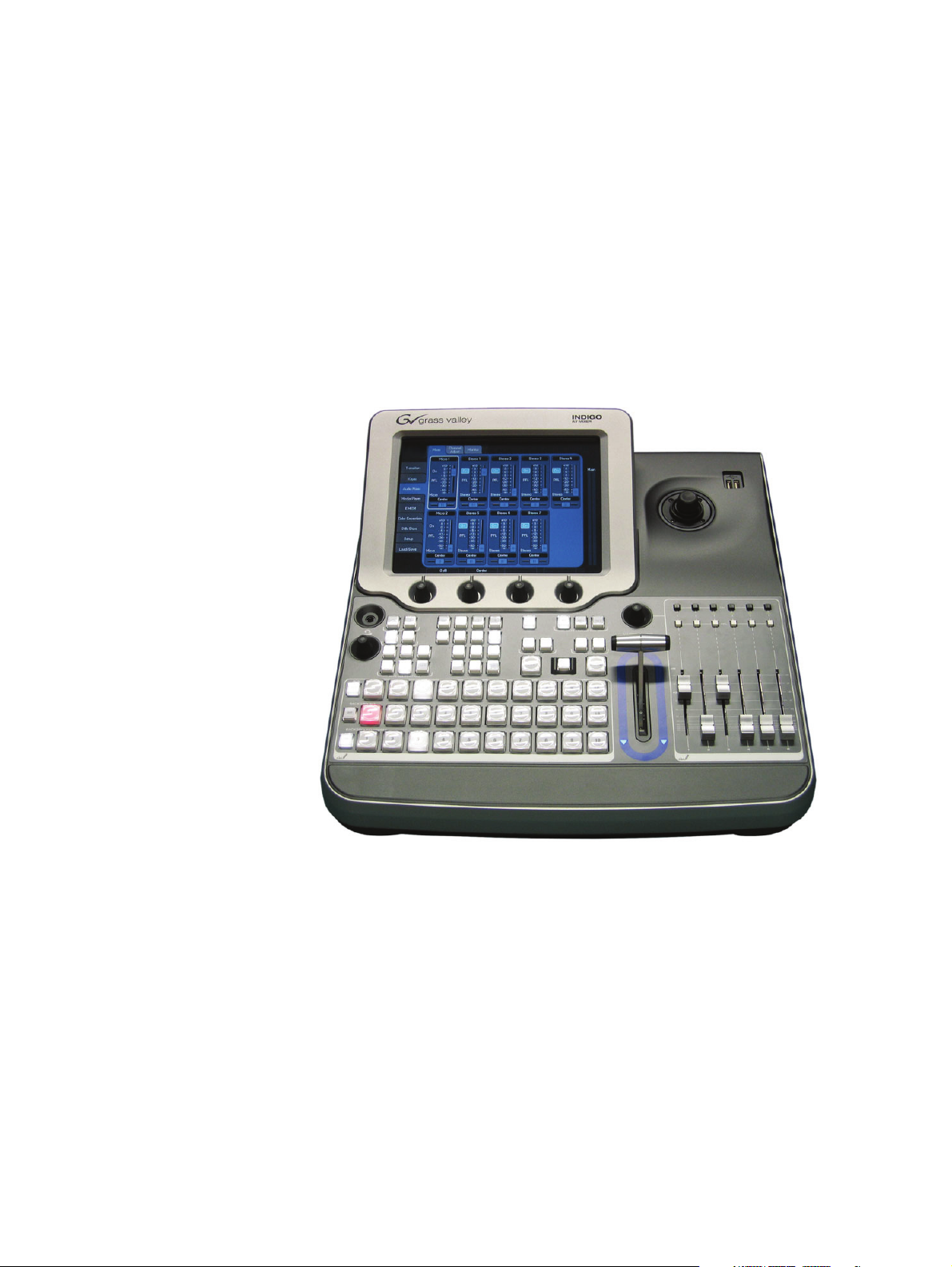
Welcome to the INDIGO AV Mixer. The INDIGO AV Mixer uniquely
combines the advanced features of a video production switcher, a seamless
switcher, and an audio mixer.
Figure 1. The INDIGO AV Mixer
INDIGO AV Mixer User Manual 13
Page 14

Section 2 — Welcome
Key features of your INDIGO AV Mixer:
• Live seamless switching of video, computer, and audio sources
• Mix digital and analog sources
• Upconvert/downconvert multiple video channels between High Resolution (HR) and SD
• SD/HR simulcast output
• Pre-programmable video layouts with keyers for picture-in-picture
and other effects
• Digital effects with 2D and 3D transformations, including page turns,
ripples, and swirls
• Linear/luminance and chroma keyers
• Integrated control of the Grass Valley Turbo™ intelligent digital disk
recorder (iDDR) and other devices
• Stereo analog and AES/EBU audio
• SDI audio de-embedding and re-embedding
• Four-band parametric equalizer and motordriven audio faders
• Simple audio-follow-video mode
• Intelligent audio-delay management for live production lip sync
2.1 About this Manual
This User Manual is intended to help you understand how your INDIGO
AV Mixer works and how to work with it.
In addition to explaining basic functionality (Basic Operation on page 37),
hardware (Connections on page 17) and software, it also provides practical
hints. The Tu t or i a l s on page 67 may give you a good starting point for creating your own setups.
The section Menus on page 73 explains the basic navigation and organization of the menus and provides a quick reference to all their functions and
buttons.
This User Manual also provides further details on how to operate the
INDIGO AV Mixer in a network (Network Operation on page 147) and how
to operate external devices (External Devices on page 149).
The section Maintenance on page 151 explains how to clean the INDIGO
AV Mixer, how to calibrate its operating elements, and how to update the
software.
Finally, the section Troubleshooting on page 159 provides tips and tricks for
dealing with most common problems on your INDIGO AV Mixer.
14 INDIGO AV Mixer User Manual
Page 15

2.2 Related Documents
You will find the complete User Manual and all Release Notes (as published so far) on the CD-ROM included in the INDIGO AV Mixer
package. It provides you with comprehensive information about your
INDIGO AV Mixer.
Users who have a general understanding of how a video/audio mixer
works and who want to start immediately, should review the
Quick Start Guide.
Additionally, you will find the following information at
www.thomsongrassvalley.com
• Online versions of Documentation — Current versions of product
catalogs, brochures, data sheets, ordering guides, planning guides,
manuals, and release notes in .pdf format are available for download.
• FAQ Database — Search our Frequently Asked Questions (FAQ) database to find quick answers to common questions and troubleshoot
problems.
Related Documents
:
2.3 Before You Begin
• Software Downloads — Software updates, drivers, and patches are
available for download.
Check whether your INDIGO AV Mixer package is complete. The fol-
lowing items are included:
• INDIGO AV Mixer device
• Two power supply cables (US and Continental Europe)
• Tally/GPI/GPO breakout box + cable (if ordered)
• Digital Audio breakout cable (if ordered)
• HiRes Board (if ordered)
• CD-ROM with the User Manual in different languages
• Multilingual Quick Start Guide
INDIGO AV Mixer User Manual 15
Page 16

Section 2 — Welcome
16 INDIGO AV Mixer User Manual
Page 17
Connections
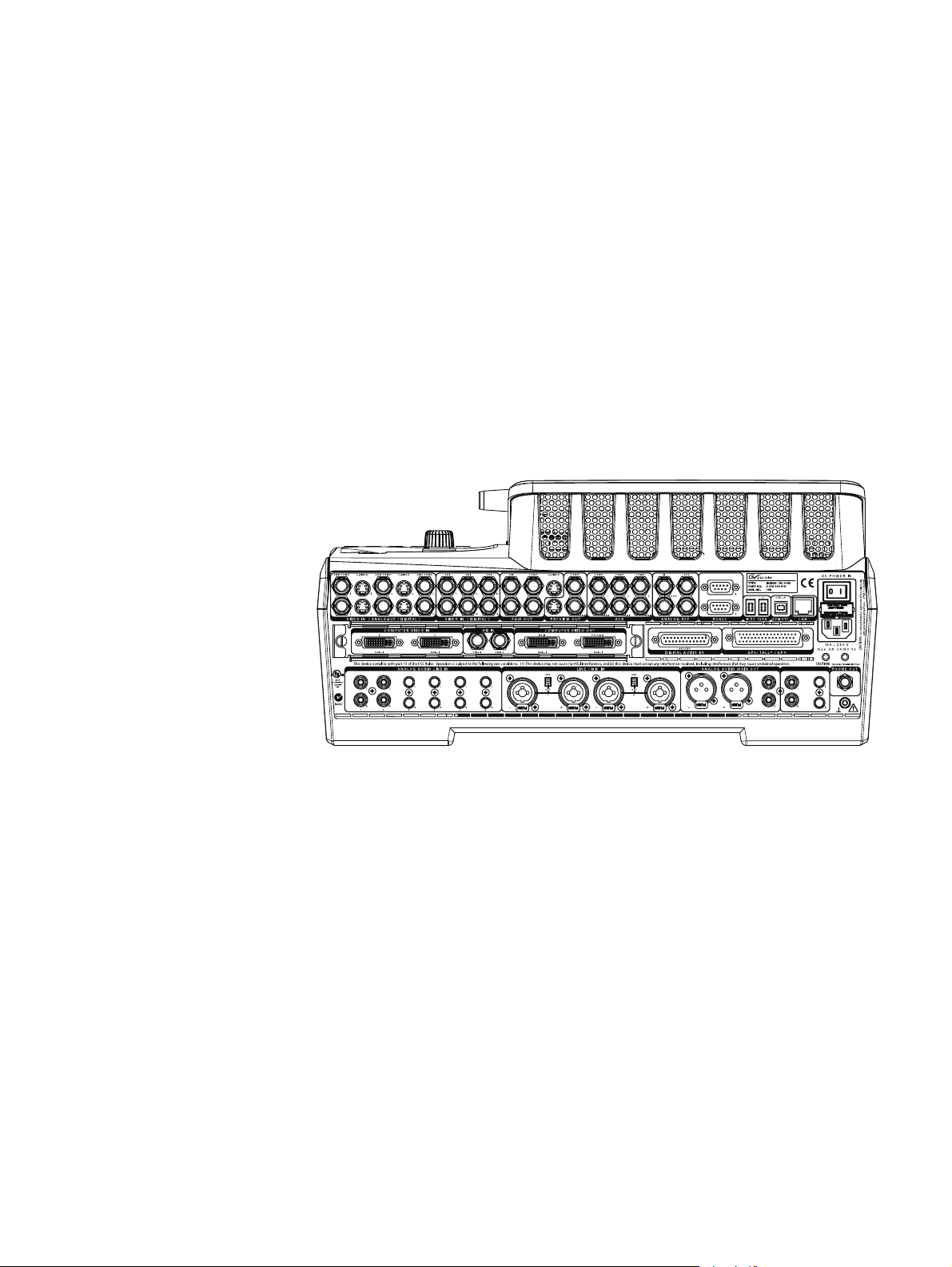
3.1 Rear Panel Overview
The following figure shows the rear panel of the INDIGO AV Mixer with
its various connectors:
Section 3
35"/54
Figure 2. Rear panel of the INDIGO AV Mixer
Note All Sub-D connectors of the INDIGO AV Mixer use SAE inch threads, not
ISO/DIN metric threads.
INDIGO AV Mixer User Manual 17
Page 18
Section 3 — Connections
3.2 Electric Power Supply
3.2.1 AC Power Cable
Use the power cable to connect the power inlet of the INDIGO AV Mixer
to the wall outlet.
Note If required, ask your dealer for an appropriate power cable.
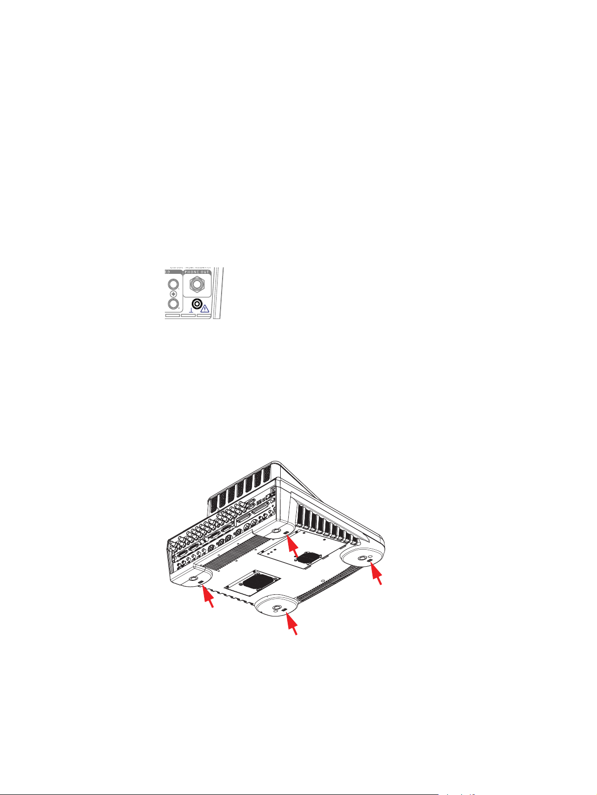
3.2.2 Ground Screw
Use the ground screw to connect the unit to the ground terminal.
Figure 3. The ground screw
3.3 Rackmount Connections
You can install your INDIGO AV Mixer in a rack using telescopic rails.
For this purpose, the device is equipped with four M5 cage nuts underneath.
Figure 4. Cage nuts for rackmounting
CAUTION To avoid damages of the unit, only use screws with a maximum length of
10 mm (0.39 inch).
18 INDIGO AV Mixer User Manual
Page 19
3.4 Video Connections
The INDIGO AV Mixer provides various analog and digital video inputs
and outputs. Via the optional HiRes board you can also make use of HD
inputs and outputs as well as internal upscaled and downscaled signals.
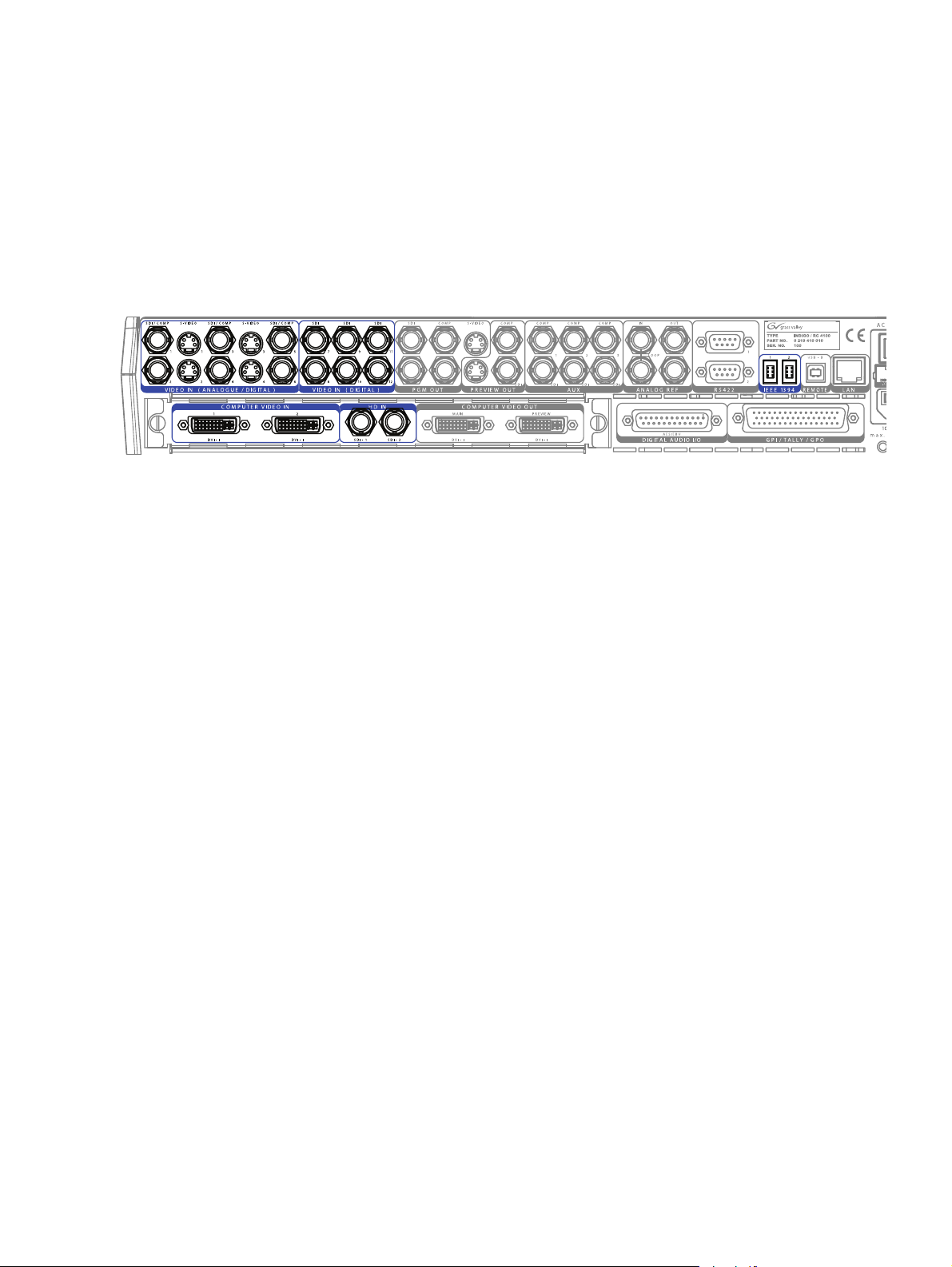
3.4.1 Video Inputs Overview
The following figure shows the video inputs of the INDIGO AV Mixer:
Figure 5. Video input connections
Video Connections
3.4.2 Video Inputs
The INDIGO AV Mixer provides various inputs for video, both analog
and digital.
Note The system can perform auto frame synchronizing for all video inputs, so
there is no requirement for genlocking.
The following inputs are available:
•12 SDI inputs, the first 6 supporting also analog formats
Supported analog formats:
• PAL B, G, H, I, M, N; Pal 60
• NTSC, NTSC M, NTSC 4.43
Supported digital formats:
• ITU-R-656 (SMPTE 259M-1997) with embedded audio (SMPTE
272M-1994)
•6 CVBS (Composite) inputs
Note The CVBS inputs share connectors with the first 6 SDI inputs.
•4 S-Video inputs, aliased with the first 4 SDI inputs
•2 IEEE 1394 (Firewire) inputs
Note The firewire inputs will replace the SDI inputs 11 and 12.
Note The Firewire connectors can also be configured as outputs.
INDIGO AV Mixer User Manual 19
Page 20
Section 3 — Connections
HiRes Board
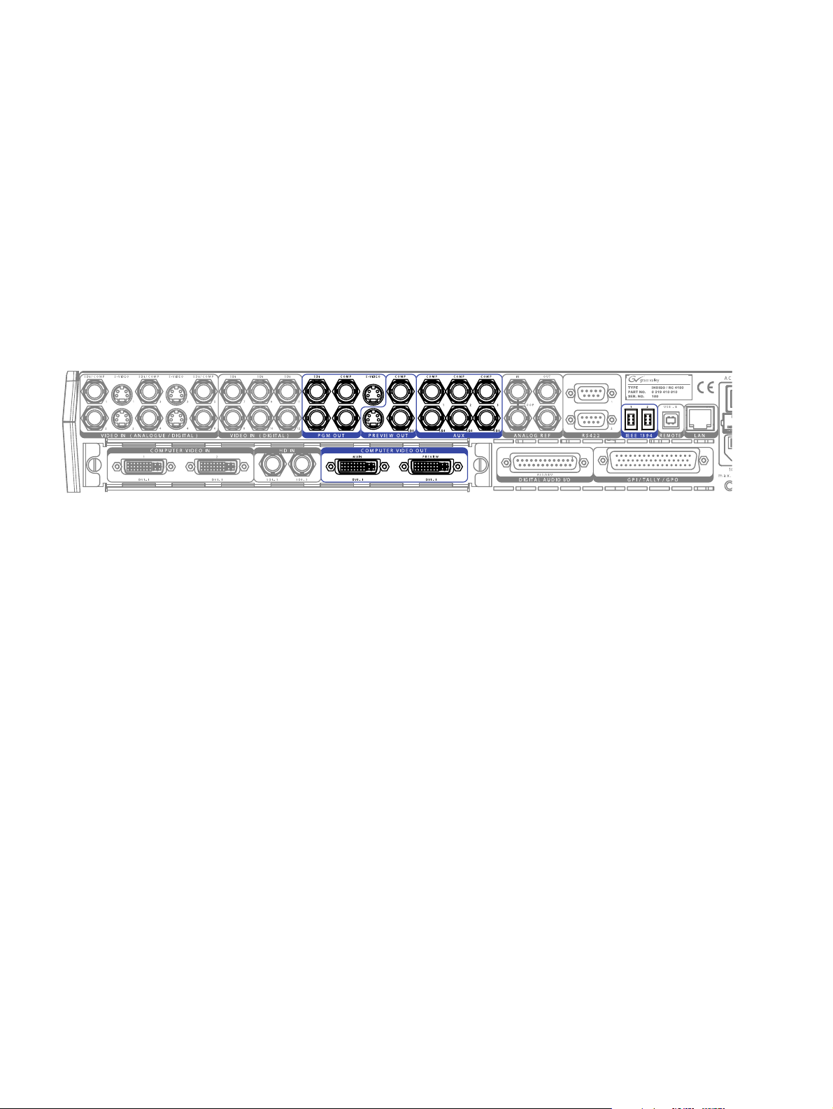
3.4.3 Video Outputs Overview
The optional HiRes board additionally provides the following video
inputs:
•2 DVI-I inputs with a resolution of up to 1920x1080 pixels
•2 HD-SDI inputs with a resolution of 1080i or 720p
Note Using an appropriate adapter, analog VGA signals can also be input via the
DVI-I connectors (see DVI-I to VGA on page 29).
The following figure shows the video outputs of the INDIGO AV Mixer:
Figure 6. Video output connections
3.4.4 Video Outputs
The outputs listed below are sorted by sections (as labeled on the rear
panel), in order to allow a quick and easy overview.
Section PGM OUT
The PGM OUT section provides the following outputs, which can be used
concurrently:
•2 x SDI
•2 x CVBS (Composite)
•1 x S-Video
Section PREVIEW OUT
The PREVIEW OUT section provides the following outputs, which can be
used concurrently:
•1 x SDI
•1 x CVBS (Composite)
•1 x S-Video
20 INDIGO AV Mixer User Manual
Page 21

Section AUX
The AUX section provides the following outputs, which can be used concurrently:
•3 x SDI
•3 x CVBS (Composite)
Note AUX outputs cannot be used in bypass mode and are always re-clocked/
timed.
Section IEEE 1394 (Firewire)
The Firewire section provides 2 outputs.
Note The Firewire connectors can also be configured as inputs.
Section COMPUTER VIDEO OUT (HiRes Board)
The optional HiRes board additionally provides the following video outputs:
Video Connections
•2 DVI-I outputs with a resolution of up to 1920x1080 pixels
Note DVI only provides progressive signals.
• 2 downscaled outputs
The downscaled outputs provide HR versions of PGM OUT and
PREVIEW OUT and are internal resources. Select one or two inputs
out of the 12 available inputs.
Note Each downscaled output will replace one SDI input (11 = PGM, 12 = PVW).
Note Using an appropriate adapter, also analog VGA signals can be output via the
DVI-I connectors (see DVI-I to VGA on page 29).
INDIGO AV Mixer User Manual 21
Page 22
Section 3 — Connections
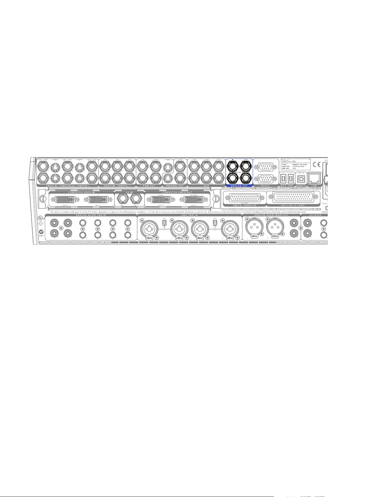
3.5 Analog Ref Connections
The Analog Ref section provides two Black Burst outputs to sync external
equipment, i.e. the INDIGO AV Mixer can be used as sync generator for
the rest of the production system.
It also provides a Black Burst input with a loop through connector to sync
the INDIGO AV Mixer to an external reference signal.
Use a terminating resistor of 75 Ohm if you connect a signal but do not
loop it through.
Note The Analog Ref connectors cannot be used as inputs or outputs for video
signals.
Figure 7. Analog Ref connections
22 INDIGO AV Mixer User Manual
Page 23
3.6 Audio Connections
35"/54
The INDIGO AV Mixer provides various analog and digital audio inputs
and outputs.
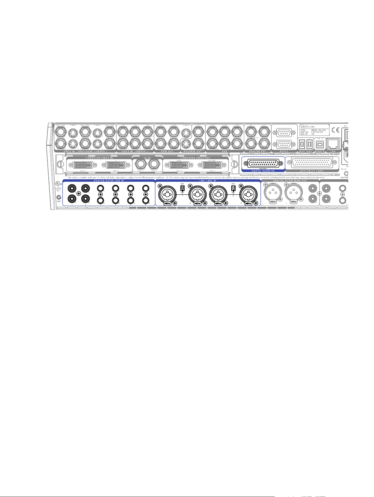
3.6.1 Audio Inputs Overview
The following figure shows the audio inputs of the INDIGO AV Mixer:
Audio Connections
Figure 8. Audio input connections
Note All XLR connectors of the INDIGO AV Mixer correspond to
IEC 61076-2-103. Only use corresponding plugs, for example, NEUTRIK.
Plugs that do not match this standard may become stuck in the jack.
3.6.2 Audio Input Types
You can connect various analog and digital audio input signals to the
INDIGO AV Mixer.
Note The maximum amount of concurrently usable audio channels is 8.
Analog Audio Input
The INDIGO AV Mixer provides the following connections for analog
audio input:
•2 x RCA (unbalanced)
•4 x TRS 1/4’’ (balanced)
INDIGO AV Mixer User Manual 23
Page 24

Section 3 — Connections
Microphone / Line In
The LINE/MIC IN section provides combined XLR/TRS 1/4’’ connectors
as inputs:
•4 x XLR
•4 x TRS 1/4’’ (the TRS 1/4’’ phone connectors are located in the middle
of the combined connectors and can be used instead of XLR)
XLR
TRS 1/4’’
Figure 9. Combined XLR/TRS 1/4’’ connector
Note Phantom power (+48 V DC) can be activated for Line/Mic inputs 1/2 and 3/4.
Note The LINE/MIC IN inputs can be amplified (see Mixer Submenu on page 97).
Digital Audio Input
The INDIGO AV Mixer provides the following connections for digital
audio input:
•6 x AES/EBU (25-pin Sub-D connector, section DIGITAL AUDIO I/O)
De-embedded/Embedded Audio (SDI)
Audio can also be derived (de-embedded) from up to six SDI video inputs
(see Audio Submenu on page 129).
For all SDI outputs, audio is embedded in Main and Sub channels in pairs
1+2 and 3+4.
Note De-embedded audio signals may be automatically delayed according to their
related video signals to avoid offset when being processed and re-embedded
on output.
24 INDIGO AV Mixer User Manual
Page 25
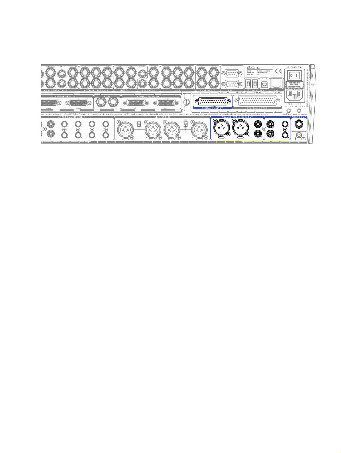
3.6.3 Audio Outputs Overview
The following figure shows the audio outputs of the INDIGO AV Mixer:
Figure 10. Audio output connections
3.6.4 Audio Output Types
The INDIGO AV Mixer provides various analog and digital audio out-
puts.
Audio Connections
35"/54
Analog Audio Output
The outputs listed below are sorted by sections (as labeled on the rear
panel), in order to allow a quick and easy overview:
Section ANALOG AUDIO MAIN OUT
These outputs can be used concurrently:
•1 x XLR (balanced)
•1 x RCA (unbalanced)
Section SUB-OUT
Sub-Out is a fully featured mixing unit. These outputs are similar to
Main Out, but additionally provide delayed output functionality (for
example, for a second pair of speakers in the middle of a bigger area or
hall). They can be used concurrently:
•1 x RCA (unbalanced)
•1 x TRS 1/4’’ (unbalanced)
Headphones
There are 2 headphones connectors, one on the top panel and one on the
rear panel. The headphone connectors may also be used for monitoring,
when connecting speakers instead of headphones.
INDIGO AV Mixer User Manual 25
Page 26
Section 3 — Connections
Digital Audio Output
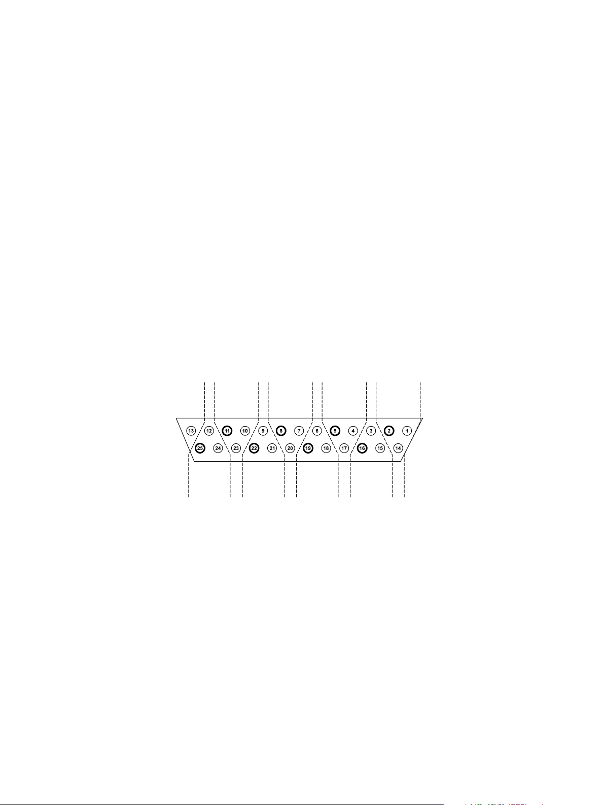
3.6.5 AES/EBU Pin Out
The INDIGO AV Mixer provides the following connections for digital
audio output:
•2 x AES/EBU (25-pin connector, section DIGITAL AUDIO I/O)
Note The first digital output provides the same audio signal as section ANALOG
AUDIO MAIN OUT.
The second digital output provides the same audio signal as section
SUB-OUT.
Additionally, the SDI outputs of PGM OUT (Section PGM OUT on
page 20) provide embedded audio (Channel 1+2 = Main, 3+4 = Sub).
Note There is no audio processing for HR sources.
Digital audio I/O are available over SD-SDI or AES/EBU. The pin out for
the AES/EBU connector is shown below.
AES/EBU DSUB 25 pins female
2x Digital Output, 6x Digital Input
OUT1com
OUT2-
OUT2com
OUT1+
IN6-
OUT1-
OUT2+
IN6com
Figure 11. AES/EBU pin out
IN6+
IN2com
IN1com
IN2+
IN1+
IN1-
IN2-
IN5com
IN5+
IN5-
IN4com
IN3com
IN4+
IN3+
IN3-
IN4-
26 INDIGO AV Mixer User Manual
Page 27

Audio Connections
The following table shows the pin assignment grouped by inputs and outputs:
Digital Audio Input Description Pin
IN1+ 1
1
2
3
4
5
6
Digital Audio Output Description Pin
1
2
IN1- 14
IN1com 2
IN2+ 15
IN2- 3
IN2com 16
IN3+ 4
IN3- 17
IN3com 5
IN4+ 18
IN4- 6
IN4com 19
IN5+ 7
IN5- 20
IN5com 8
IN6+ 21
IN6- 9
IN6com 22
OUT1+ 10
OUT1- 23
OUT1com 11
OUT2+ 24
OUT2- 12
OUT2com 25
Note The optional adapter INDIGO1-AUDIO_CABLE connects two XLR outputs
and six XLR inputs with the 25pin AES/EBU connector of your INDIGO AV
Mixer. The cable length is three meters.
INDIGO AV Mixer User Manual 27
Page 28
Section 3 — Connections
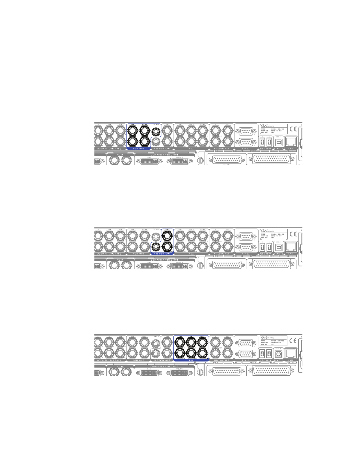
3.7 Monitors
3.7.1 Program Monitors
The INDIGO AV Mixer provides program, preview, and auxiliary
monitor outputs.
Program monitors are connected to the outputs in the PGM OUT section.
You can connect up to five program monitors in parallel.
Figure 12. Program monitor connections
3.7.2 Preview Monitors
Preview monitors are connected to the outputs in the PREVIEW OUT
section. You can connect up to three preview monitors in parallel.
Figure 13. Preview monitor connections
3.7.3 Auxiliary Monitors
Use the connectors of the AUX section to output special signals, for
example, a single keyer signal, to check on a separate monitor. You can
connect up to three auxiliary monitors in parallel.
Figure 14. Preview monitor connections
28 INDIGO AV Mixer User Manual
Page 29
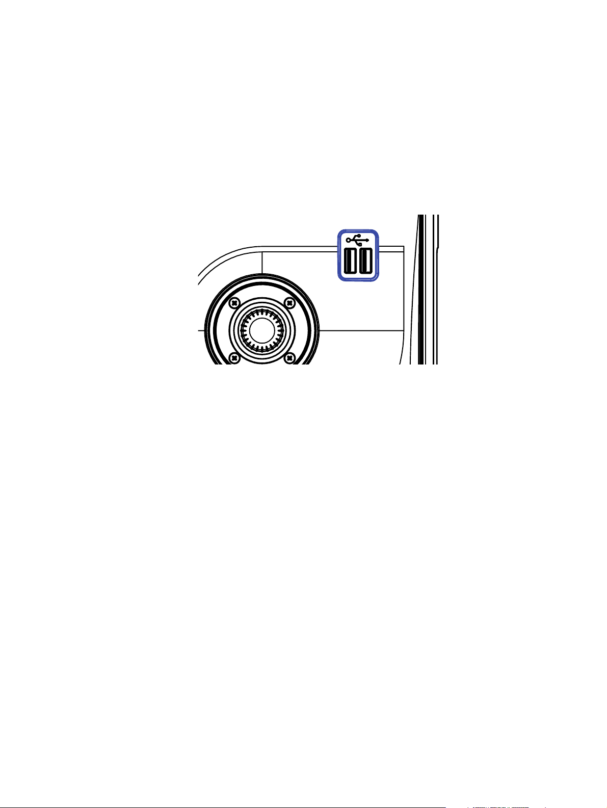
3.8 USB Ports
USB Ports
The INDIGO AV Mixer provides 3 USB ports: one on the rear panel and
two on the top panel.
Note The USB port on the rear panel is for future use and currently without func-
tion.
The USB ports on the top panel allow you to connect USB devices like USB
sticks or USB drives to store and load data (for example, user settings or
images).
3.9 Adapters
3.9.1 DVI-I to VGA
3.9.2 DVI-I to DVI-D
Figure 15. USB ports on the top panel
Note To ensure proper function, use only USB sticks that are tested and confirmed
by GrassValley.
The DVI-I outputs of the INDIGO AV Mixer provide both DVI and VGA
signals. If you want to connect standard VGA monitors you need an
appropriate adapter or breakout cable.
You do not need an adapter to connect DVI-D devices to the DVI-I inputs
and outputs of the INDIGO AV Mixer.
3.9.3 DVI-I to HDMI
You can use conventional adapters to connect HDMI devices to the DVI-I
inputs and outputs of the INDIGO AV Mixer.
INDIGO AV Mixer User Manual 29
Page 30
Section 3 — Connections
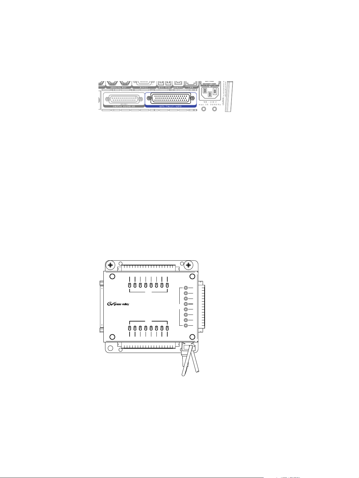
3.10 Tally/GPI/GPO
Use the GPI / TALLY / GPO 50-pin Sub-D connector to control external
devices via relays, or to send and receive control signals and events.
Figure 16. GPI / TALLY / GPO connector
The GPI / TALLY / GPO connector provides:
• 16 outputs, usable as tally out or GPO
This lets you open and close connections between two corresponding
pins of the connector, to control external devices or relays.
• 8 inputs, usable as tally in or GPI
By opening/closing the connection between two corresponding pins
of the connector, you activate functions like transitions or audio
channel on/off (see GPIO Submenu on page 138).
Tally Breakout Adapter
The optional Tally Breakout Adapter provides an easy way to use the
GPI / TALLY / GPO connector.
16 15 14 13 12 11 10 9
3V3 GND
3V3
OFF
GND
INDIGO GPI / TALLY / GPO BREAKOUT ADAPTER
GND
OFF
3V3
Figure 17. Tally Breakout Adapter
GPO
GPO
8
7
6
5
GPI
4
3
2
1
87654321
5V=
3V3GND
30 INDIGO AV Mixer User Manual
Page 31

Tally/GPI/GPO
It comes with a wall mount adapter (EU and USA) for power supply with
5 V DC and 10 W maximum power. If required, ask your dealer for a different adapter.
You may also develop your own breakout box or simply connect the pins
that you need for your application.
GPI/GPO Interface
In the following you can see the pin assignment of the GPI/GPO connector
and how to connect the inputs and outputs of the interface.
GPI/GPO Connector
A pair of two pins of the GPI/GPO connector represents one input or one
output. The following table shows the corresponding pin assignments:
GPI Pins GPO Pins
1 1, 2 1 22, 23
2 18, 19 2 8, 9
3 34, 35 3 24, 25
4 3, 4 4 41, 42
5 20, 21 5 10, 11
6 36, 37 6 26, 27
7 5, 6 7 43, 44
8 38,39 8 12, 13
9 28, 29
10 45, 46
11 14, 15
12 30, 31
13 47, 48
14 16, 17
15 32, 33
16 49, 50
1JOT
1JOT
1JOT
Figure 18. 50-pin Sub-D plug for GPI/GPO features
INDIGO AV Mixer User Manual 31
Page 32

Section 3 — Connections
Interface Connections
The following figure shows how to connect GPI 1 of the GPI interface, as
an example. The other inputs are connected the same way:
9
3
[
/
'
5
5
'(/327'06
QHHUJ
J
Q
7*
HGLXJW
/
KJL
PP
7
-
-
'1*
-
-
Figure 19. GPI interface
The following figure shows how to connect GPO 1 of the GPO interface, as
an example. The other inputs are connected the same way:
93
'
7
9$%
-
-
Figure 20. GPO interface
5
*
1
'
5
B0
B23*
2&
3*
B2
-
-
-
-
-
-
93
'1*
32 INDIGO AV Mixer User Manual
Page 33

Initial Settings
If you switch on your INDIGO AV Mixer for the first time or use a new
setup (i.e. you connected different or additional devices) you have to
adjust the video and audio settings after first power-on.
4.1 Power-On
Use the power switch on the rear side to switch on your INDIGO AV
Mixer.
Section 4
Figure 21. The power switch
4.2 Video Settings
Configure the video settings as needed, according to the connected
devices:
1. Select the SETUP main menu (see Setup Main Menu on page 116) to make
your settings.
2. In the VIDEO submenu (see Vide o Sub menu on page 120), press the Input
button to list all video inputs and set the signal Ty pe for each (used)
video input.
3. Press the Output button and select the desired Graphic Standard
(resolution) and Type (PAL or NTSC).
INDIGO AV Mixer User Manual 33
Page 34

Section 4 — Initial Settings
4. If desired, in the CONTROL PANEL submenu (see Control Panel Submenu on
page 135), press
video Sources are routed to which Buttons on the Background
crossbar.
By default, the buttons are assigned corresponding to the number of
the video signal input channel, for example, the signal from video
input 2 is routed to button
Shift+10
4.3 Audio Settings
To adjust the audio settings:
1. Select the SETUP main menu (see Setup Main Menu on page 116).
2. In the AUDIO submenu (see Audio Submenu on page 129), press the
Operation Mode button to select one of the following modes:
Button Assign and set the video signal routing, i.e. which
2, SD stills are assigned to buttons Shift+3 to
.
8 Stereo: You can use the audio signals of eight stereo sources,
•
deriving from RCA, TRS 1/4’’, XLR, AES/EBU signals or even deembedded audio from video streams.
7 Stereo, 2 Mic: You can use seven stereo audio signals (deriving
•
from RCA, TRS 1/4’’, XLR, AES/EBU signals or even deembedded audio from video streams) and two microphones that
are connected to LINE/MIC IN inputs.
6 Stereo, 4 Mic: You can use six stereo audio signals (deriving from
•
RCA, TRS 1/4’’, XLR, AES/EBU signals or even de-embedded
audio from video streams) and up to four microphones that are
connected to LINE/MIC IN inputs.
Note When assigning an XLR connector to a Mic Input, the corresponding Gain
parameter in Audio Mixer changes from Channel Gain to Mic Gain, indicating
the individually used pre-amplifier circuits.
3. If desired, in the CONTROL PANEL submenu (see Control Panel Submenu on
page 135), press
audio source is routed to which fader in the Audio Control Subpanel
(see Tu to r ia l s on page 67).
By default, the faders are assigned according to the number of the
audio signal input channel, for example, the signal from audio input 3
is routed to fader
Fader Assign and set the audio signal routing (i.e. which
3.
34 INDIGO AV Mixer User Manual
Page 35

4.4 Example Setup
The following figure shows a possible setup:
Example Setup
Figure 22. Connections for a big event setup
See more examples and how to adjust the corresponding setups in the
section Tu to r i al s on page 67.
INDIGO AV Mixer User Manual 35
Page 36

Section 4 — Initial Settings
36 INDIGO AV Mixer User Manual
Page 37

Basic Operation
5.1 Overview of Control Features
5.1.1 Control Panel
The INDIGO AV Mixer is operated by using the buttons, Digipots, lever
controls, and the graphical menu on the Touch Screen.
The buttons on the Control Panel are used during live operation for fast
and real time control. The menus, accessed via the Touch Screen, allow full
control and edit facilities and are mainly used to set up effects and for
system configuration.
Section 5
The control features of the INDIGO AV Mixer are grouped by function-
ality into the following main sections:
•(1) Touch Screen with Digipots (see page 38)
•(2) Delegation Subpanel (see page 39)
•(3) Crossbars for Bus and Source Selection (see page 40)
•(4) Main Transitions Subpanel with Transition Lever Arm (see page 41)
•(5) Numeric Input Subpanel (see page 43)
•(6) Audio Control Subpanel (see page 44)
•(7) Joystick (see page 45)
INDIGO AV Mixer User Manual 37
Page 38

Section 5 — Basic Operation
The following figure shows the Control Panel of the INDIGO AV Mixer
with its various control features:
INDIGO
AV MIXER
1
Learn
2
4
5
3
12
USER
USER
SD Hi-Res
DELEGATE
DELEGATE
Key 1
Key 2 FS
Aux 1
Aux 2 Aux 3
BUS DELEGATION
BUS DELEGATION
BUS
BUS
Shift
12345678910
BACKGROUND
BACKGROUND
Shift
12345678910
BACKGROUND PRESET
BACKGROUND PRESET
Shift
12345678910
+/-
Shift
Del Enter
789
456
123
0
Figure 23. Control Panel
BGD Key 1 Key 2
FX
NEXTTRANSITI ON
NEXTTRANSIT ION
Cut AutoCut Auto
FTB
CUT AUTO
5.1.2 Touch Screen with Digipots
7
ON
ON
PFL
MASTERVOLUME
MASTER VOLUME
KEY 2KEY 1
KEY 2KEY 1
dB
dB
+10
+10
+5
+5
+0
+0
-5
-5
-10
-10
-15
-15
-20
-20
-30
-30
-40
-40
-50
-50
-00
-00
PFL
123456
123456
+10
6
+10
+5
+5
+0
+0
-5
-5
-10
-10
-15
-15
-20
-20
-30
-30
-40
-40
-50
-50
-00
-00
Touch Screen
The Touch Screen allows direct interaction with menu controls displayed
on the screen. The screen is designed to work with a finger or other soft
objects. The Touch Screen is sensitive to a single pressure location only, so
only one touch surface control can be adjusted at a time.
CAUTION Do not apply any sharp or rigid object (no pens or pencils) to the Touch
Screen display surface.
If Auto Menu Delegation in the lower left corner is unlocked (see Auto Menu
Delegation on page 77), the menus will follow the related Control Panel
buttons. For example, pressing the
submenu of the
TRANSITION main menu on the screen.
See General Handling of the Menus on page 73 for detailed information on
how to use the menus.
38 INDIGO AV Mixer User Manual
FX button displays the EFFECTS
Page 39

Digipots
The Digipots below the graphical display can be used to dial in parameter
values for functions displayed on the Touch Screen. Pressing a Digipot sets
the parameter value to default.
5.1.3 Delegation Subpanel
532%
3
$(I2
$%,%' !4%
+
YE
XU!
"53 $%,%'!4)/.
S
E
YE+3&
XU!XU!
Overview of Control Features
Figure 24. Delegation Subpanel
User
Use buttons 1 or 2 to quickly and directly access a specific point in the
menu hierarchy, for example, to call up Calibration in the
menu.
To assign a specific menu screen to button
menu screen and press and hold button
Delegate
Use the DELEGATE section to determine which M/E is active: SD or HiRes.
Bus Delegation
The INDIGO AV Mixer M/Es include multiple sources as well as keyers
and aux buses.
To simplify use, the INDIGO AV Mixer panels provide alternate buses
accessed by
change which bus is affected by pressing a source select button on the
Bus Crossbar. You can select between
SETUP main
1 (or button 2), open the desired
1 (or button 2) for two seconds.
BUS DELEGATION buttons. Press a BUS DELEGATION button to
• Key sources (
• Auxiliary output sources (
Key 1 or Key 2)
Aux 1 to Aux 3)
See Selecting Sources on page 46 for further information.
Note Auxiliary output delegation is only available for SD.
INDIGO AV Mixer User Manual 39
Page 40

Section 5 — Basic Operation
5.1.4 Crossbars for Bus and Source Selection
The INDIGO AV Mixer includes several inputs which can be used univer-
sally for video or key signals.
"53
TFIH3
"!#+'2/5 .$
TFIH3
"!#+
'2/5.$02%3%4
TFIH3
Figure 25. Crossbars for Bus and Source Selection
Note Use the Shift buttons to access numbers 11 to 20 on the Bus, Background,
and Background Preset Crossbars.
By default, the buttons 1 to 10 and Shift+1 and Shift+2 correspond to the
sources IN01 SD to IN12 SD, the buttons
Stills 1 to 8 (for button assignment see also Control Panel Submenu on
page 135).
Bus
The Bus Crossbar is used to select key and fill signals as well as sources for
AUX 1 to 3.
See Delegation Subpanel on page 39 for information on the types of buses
that can be assigned to the crossbar and how to select them.
Background
The Background Crossbar indicates which signal is selected as the current
background picture. Pressing another key in this row performs a hard cut
to another background picture. The selected background picture can be
viewed on the corresponding program monitor.
Background Preset
The Background Preset Crossbar is used to pre-select and indicate the
background involved in a signal transition. The preset background picture
and the selected modifications (for example, keys) can be viewed on the
corresponding preview monitor.
Shift+3 to Shift+10 correspond to
The background and preset buses operate in “Flip-Flop” mode. After the
background transition is complete, the preset source is automatically
selected on the background bus and the original background source is
automatically “flipped” to the preset bus.
40 INDIGO AV Mixer User Manual
Page 41

Overview of Control Features
5.1.5 Main Transitions Subpanel with Transition Lever Arm
The transition controls are used to select the signal elements that will be
involved in the transition (background and/or keys), define the type of
transition and perform the transition.
The control is performed in two sections:
Main Transition Section with all main controls for transitions
•
Transition Lever Arm for manual transition control
•
Main Transition Elements
Use the Key 1, Key 2, and BGD buttons in the NEXT TRANSITION section to select
the elements that will change during the next transition.
Use the
CUT and AUTO buttons and the Transition Lever Arm to perform main
transitions. After a transition is complete, the background source selections flip-flop, readying the Background Preset bus for the next source
selection.
9
'
V
$U
$
Figure 26. Main Transition Section
J.
56
Y
%ZF, ZF,
#(
/&9553"/4*5*0/
V
$U
,&:,&:
'5#
YJ.
056"
Next Transition
Pressing these buttons does not change the current output of the switcher,
but prepares for a change (the next transition). The
includes the following buttons:
NEXT TRANSITION section
BGD - Background Transition
•
Use the
BGD button to select a change in the Background buses. The
result will be a transition from the current source on the Background
bus to the source selected on the Background Preset bus. After the transition, the buses will flip flop, so the Background bus always remains
the on-air bus. The Background bus selection remains the background
source if this button is not selected as part of the next transition.
INDIGO AV Mixer User Manual 41
Page 42

Section 5 — Basic Operation
• Key 1 and Key 2
Use the Key 1 and Key 2 buttons to select the keyers that will be involved
in the next transition. The Background bus selection remains
unchanged if one of these buttons is selected for the next transition.
Note A keyer may be on, but not visible (for example, half way through a preset
black transition).
Key 1 and Key 2
Cut
An instantaneous switch from one picture to another. Switching circuitry allows cuts only during the vertical interval of the video signal
to prevent disruption of the picture.
Mix
A transition between two video signals in which one signal is faded
down as the other is faded up.
Also called a dissolve (blending a new video into the existing image).
When applying an effect, it gradually blends in the effect.
CUT
Instantaneously replaces the selected elements with their new sources or
states, regardless of the transition type selected.
AUTO
Starts an automatic transition of a predetermined rate, either from one
video to another or when applying an effect. The duration can be set in the
DURATION submenu (see page 82).
Pressing
point. The transition can then be completed by pressing the button a third
time or by moving the
Auto a second time during a transition pauses the transition at that
Transition Lever Arm to its opposite limit.
FTB (Fade to Black)
This button fades the video out to or in from a black screen. Audio signals
fade out to or in from silence.
FX
Activates the selected effects for each layer and makes them usable for
transitions. The effects are selected and adjusted in the
menu.
TRANSITI ON main
FX button is deactivated, the selected effects are ignored and Mix is
If the
used for transitions.
See Transition Main Menu on page 77 for information on selecting effects.
42 INDIGO AV Mixer User Manual
Page 43

Transition Lever Arm
Figure 27. Transition Lever Arm
The Transition Lever Arm is used to manually perform a transition. You can
move the lever in either direction to run a transition due to the flip-flop
architecture of the buses. Moving the lever from one limit to the other performs a complete transition.
It is possible to start a transition with the lever, then stop moving the lever
at any point, reverse its direction, and even return it to the original limit
without completing the transition.
Overview of Control Features
5.1.6 Numeric Input Subpanel
Use the Numeric Input Subpanel to enter numbers, for example to enter
the standardized identification number for effects in the
Use the
to confirm your entries.
You can also adjust parameter values via the Numeric Input Subpanel. In
this case, the
button outputs the minus sign (“-”).
Figure 28. Numeric Input Subpanel
Del button to delete the last digit entered and press the Enter button
Shift button outputs the decimal point (“.”) and the Learn
,EARN
TFIH3
L
E$
ETN%
EFFECTS submenu.
R
INDIGO AV Mixer User Manual 43
Page 44

Section 5 — Basic Operation
5.1.7 Audio Control Subpanel
You can use the Numeric Input Subpanel to store and call up E-MEMs.
These are mixer state presets (see E-MEM Main Menu on page 107 for
further information). Use the numeric keys to have quick access to the first
20 presets. Access numbers 11 to 20 with the
Shift button. In the E-MEM main
menu, you can access stored presets with a number higher than 20.
Learn
Waits for the next state to be saved to E-MEM via Enter.
/.
0&,
4%26/,5-%
-!3
Figure 29. Audio Control Subpanel
Mute/PFL Buttons
PFL (Pre-Fader-Listening)
Changes to PFL mode. This allows you to hear the audio signal on the
headphones as it sounds before the fader.
On
"D
Turns the related audio channel on/off.
44 INDIGO AV Mixer User Manual
Page 45

LED Peak-Meters
The meters read the inputs assigned to the faders and display the channel
levels with three different colors:
Overview of Control Features
• Green: from - to -6 dB
• Yellow: -6 dB to -2 dB
• Red: -2 dB to +10 dB
Faders
The faders adjust the input levels of the audio assigned to the INDIGO AV
Mixer channels within the range of - to +10 dB.
Use them to level the volumes of different audio sources.
Master Volume Button
The Master Volume Button lets you adjust the overall volume.
Headphones
The phones connectors output the Main out, Sub-Out or channel PFL
signal.
There are 2 phones connectors: one on the Control Panel and one on the
rear panel. They have the same source, but separate amplifiers.
∞
∞
5.1.8 Joystick
The Joystick in the upper right section of the INDIGO AV Mixer provides
easy positioning and sizing of keys (for example, positioning PIPs). On
Chromakey, the Joystick can be used to position the cursor for selecting the
color area to perform the key processing.
INDIGO AV Mixer User Manual 45
Page 46

Section 5 — Basic Operation
5.2 Selecting Sources
This section provides information on selecting sources as video and audio
signals, keys sources, and Stills.
Configure and route the input and output sources for both video and
audio signals in the
5.2.1 Video
Select video signals with the crossbar buttons (see Crossbars for Bus and
Source Selection on page 40). Use the
sources to the buttons.
"53
TFIH3
"!#+'2/5 .$
TFIH3
"!#+
'2/5.$02%3%4
SETUP main menu (see Setup Main Menu on page 116).
SETUP main menu to assign video
TFIH3
See also Video Settings on page 33 for information on configuring video set-
tings.
Video Sources
The video signals for the program monitors are selected in the middle
crossbar row, labeled as
forms a hard cut to another signal.
Select the input and output sources in the
Video Sub men u on page 120), and assign the signals to the crossbar buttons
in the
CONTROL PANEL submenu (see Control Panel Submenu on page 135).
Keys Sources, Auxes and Stills
Key and fill signals, and auxiliary outputs are selected in the top crossbar
row, labeled as
selecting the types of sources.
Select and adjust the key and fill sources in the
Keyer Main Menu on page 83).
BUS. See Bus Delegation on page 39 for information on
BACKGROUND. Pressing another key in this row per-
VIDEO submenu under SETUP (see
KEYERS main menu (see
To save a Still (capture a video frame) from a currently displayed video,
use the Stills Store menu (see Stills Store Main Menu on page 112).
46 INDIGO AV Mixer User Manual
Page 47

Preview of Signal Transitions
Onscreen Preview
5.2.2 Audio
Selecting Sources
The preset background involved in a signal transition together with the
selected modifications (for example, keys) is selected in the bottom
crossbar row, labeled
the selected preset background on the corresponding preview monitor
(LAH preview).
The Onscreen Preview window lets you display program, preview, and
aux1/2 signals of SD outputs directly on the Touch Screen
(see Onscreen Preview on page 75).
Use the faders and the AUDIO MIXER main menu to control the audio signals
(see Audio Mixer Main Menu on page 97).
BACKGROUND PRESET. Pressing a key in this row shows
Use the
(see Control Panel Submenu on page 135).
You can assign an audio stream to a video source (see Audio Follow Video
on page 64).
See also Audio Settings on page 34 for information on configuring the audio
settings.
CONTROL PANEL submenu to assign the audio channels to the faders
INDIGO AV Mixer User Manual 47
Page 48

Section 5 — Basic Operation
5.3 Video Processing
This section shows you how to make transitions, effect transitions, titles,
and chroma keys.
5.3.1 Transitions, Effects, and Keying
The INDIGO AV Mixer provides various ways to manipulate and mix
video signals. The most common ways are described in the following.
The first part of this section provides some theory and basic information
about transitions and keying.
The second part provides examples for:
• Making a background transition
• Making a title
• Making a chroma key
• Making an effect transition
• Making a PiP (Picture in Picture)
Transitions
A transition is a change from one image to another. It can be applied to the
entire picture, or to only the background or keyed elements of the picture.
It may include multiple elements.
The INDIGO AV Mixer supports the following types of transitions:
•Cut
•Mix
•Wipe
Cut
A cut is an instantaneous switch from one image to another (between successive video fields or frames). The simplest type is a hot cut, accomplished by selecting a different source on a bus feeding an M/E output.
This only changes that bus’ contribution to the output, and does not
change what elements may be involved in the output (the same buses are
involved).
48 INDIGO AV Mixer User Manual
Page 49

Video Processing
The INDIGO AV Mixer also provides cut transitions, where the elements
involved in a mixed output can be changed instantaneously. Different
buses can be included or excluded, causing changes in the resulting composite image. Background cut transitions on the M/E are first selected on
the Background Preset bus to allow the upcoming picture to be previewed
before it is cut “On Air”.
Mix
A mix is a transition from one picture to another where the new picture
fades in as the existing picture fades out. During a standard mix transition,
a superimposition of both pictures, each at a lower intensity, is visible.
The INDIGO AV Mixer allows mixing from one background to another
and to mix up to two separate keys on or off over a background. Background and key mixes can be done separately or simultaneously.
Wipe
A wipe is a transition from one picture to another in which the edge of a
shape moves across the screen, revealing the new picture. Wipe transitions
can be applied to backgrounds, keys, or both simultaneously. A wipe transition shape can be selected from a variety of patterns. These patterns can
be adjusted in several ways (for example, the edge attributes).
Fade to Black (FTB)
Fade to Black is a special type of transition where the picture transitions to
black and then out of black to the new picture. Fade to Black actually
involves two transitions: one to black and one from black. Therefore, it
requires two operator commands to complete. The entire picture goes to
black even if all the transition elements involved in the picture were not
selected.
INDIGO AV Mixer User Manual 49
Page 50

Section 5 — Basic Operation
Keying
Keying inserts a part of one picture into another to create a composite picture. Keying involves three signals:
• Background
• Key cut, used to specify where to cut a hole in the background
• Key fill, used to fill the hole in the background
The fill can be an incoming video signal or it can be an internally generated
matte fill. A separate key cut input signal is not necessarily required for
keying. For example, a self key (also called a video key) uses the same
input signal for both key cut and key fill.
Key Control Signal Adjustment
During keying, the selected key cut signal can be converted into a key
control signal. It is the key control signal that actually cuts the hole in the
background video. Adjusting the key control signal (Clip and Gain) is
essential in the keying process. The art of setting up a good key is to use
just enough Gain to suppress any imperfections in the incoming key signals. Setting Gain too high can cause ragged key edges.
The INDIGO AV Mixer provides two methods for adjusting the key
control signal:
•Clip and Gain
• Cleanup and Density
Note that both of these methods control the same basic keying process.
Clip and Gain
The Clip and Gain operation selects a threshold of the selected key cut
video that will be used to cut the hole in the background video. Clip
controls the threshold, and Gain controls the softness of the key edges
and any translucent areas. High portions of the key cut signal specify
what video is retained, and low portions determine what video is
removed. Intermediate levels specify a soft blend of the background
and fill video.
Cleanup and Density
The Cleanup and Density operation influences only one end of the key
area and keeps the other one constant. Cleanup only influences the
background area. Key levels are increasingly limited to black, i.e.
”cleaned”. Noise and slight shadows in this area will disappear.
Density only influences the foreground area. Key levels are increasingly limited to white to the unity value ”1”, which corresponds to the
”dense” foreground.
50 INDIGO AV Mixer User Manual
Page 51

Video Processing
Key Invert
Keys can be inverted, causing holes to be cut in the background where
a normal key retains the background, and vice versa. Key invert makes
the white areas of the key cut signal produce transparency, and the
black areas produce opacity, the opposite of a standard key.
Border
The Border feature generates borders around keys. The key signal is
delayed and/or enlarged, and the extra bordering space can be filled
with matte. Border can be adjusted in size and in horizontal and vertical placement. Variations include Outline, Extrude and Drop.
Opacity
The opacity of a key can be adjusted. When opacity is reduced below
100% some background video is allowed to show through areas where
it is normally excluded. Key opacity is an adjustment to the overall
intensity of the key and is separate from Clip and Gain controls. Note
that a common mistake is to set opacity to zero and forget that adjustment was made, which can cause confusion later when that key is
selected but not visible.
The INDIGO AV Mixer supports the following types of keys:
• Luminance Key
•Chroma Key
• PiP (Picture in Picture)
Two of the keys, Luminance Key and Chroma Key, are described in detail in
the following.
INDIGO AV Mixer User Manual 51
Page 52

Section 5 — Basic Operation
Luminance Key
A luminance key uses the luminance of an incoming source to specify where
to cut the hole in the background. Luminance keying is typically done on
sources that do not have an accompanying key cut signal, like a video
camera. The key cut signal must be generated from the incoming video
signal, using clip and gain controls. When only one source is used for both
key cut and key fill, the key is called a Self key or Video key. The same key
source signal is multiplied by the key cut signal to create the key fill, and
then the signals are summed.
X
Background Video Key Hole Background
Clip
Gain
Invert
+
Key Control
X
Key Source (video only)
Figure 30. Luminance Key
Clip and Gain controls for luminance keys offer wide adjustment ranges.
Key Fill
Completed
Luminance Key
52 INDIGO AV Mixer User Manual
Page 53

Video Processing
Chroma Key
A chroma key is a key that detects color (rather than luminance) in a video
image and replaces it with a new background. For example, a reporter may
be in a studio sitting in front of a backdrop with a blue or green backing
color, and the new background can be a mountain scene. The completed
chroma key consists the mountain scene replacing the backing color, creating the illusion that the reporter is sitting in front of the mountain.
X
Background Video
Chroma Key Source
(video only)
Backing Colors Selected
Chroma Key
Primary
Suppression
Clip
Gain
Invert
Invert
Key Control
Key Hole Background
+
Chroma Key
Secondary
Suppression
Completed
Chroma Key
X
Chroma Key Fill
Backing Color Suppressed
Figure 31. Chroma Key
INDIGO AV Mixer User Manual 53
Chroma Key Fill
Backing Color Removed
Page 54

Section 5 — Basic Operation
The terms foreground and background are often a source of confusion
when used for chroma keys. Foreground refers to the people or objects in
a chroma key scene that are in front of the colored backdrop. Background
refers to the scene that will replace the backing color (same as a linear or
luminance key) in the final picture. Background does not refer to the backdrop of the foreground scene.
Chroma keys are performed by suppressing the backing color in the foreground scene, cutting a hole in the background, and then combining the
two processed signals. When conditions are ideal, complete suppression
of the backing color is possible and the hole cut in the background will
match the suppressed foreground, permitting these two signals to be
added successfully.
54 INDIGO AV Mixer User Manual
Page 55

5.3.2 Making a Background Transition
To make a background transition:
1. Select SD or HiRes [DELEGATE].
3
$(I2SE
$%,% '!4%
2. Select the desired source on the Preset bus.
"!#+
'2/5.$02%3%4
TFIH3
3. Make sure background transition is selected, i.e. the BGD [Next Transition]
button is ON.
$YE+ YE+
"'
.
%8442!.3)4)/.
4. If necessary, select the TRANSITION main menu, select the SD EFFECTS or
HR EFFECTS submenu (depending on delegation), and press SD BGND or
HR BGND.
Video Processing
5. Select the desired category and the pattern, for example, 3D and Ripple.
See SD/HR Effects Submenu on page 78 for further information.
Note If the FX button is OFF, only Mix is used for transitions. If FX is ON, the
selected effects are used for transitions.
Note For HiRes, only Wipes and Mix are available.
6. Press the AUTO button.
#
45
&4"
/45!
See Duration Submenu on page 82 if you want to modify the duration
of the Auto transition.
– or –
Move the
Transition Lever Arm to the opposite position.
INDIGO AV Mixer User Manual 55
Page 56

Section 5 — Basic Operation
5.3.3 Making a Title
This type of transition inserts a text into the background scene. The background remains unaffected.
A title is based on a luminance key (see Luminance Key on page 52).
Note The following example uses Key 1 in SD mode, but you can also use Key 2
and/or HiRes mode.
To make a title:
1. Select Key 1 [NEXT TRANSITION].
Auto Menu Delegation is unlocked, the KEYER menu is selected automat-
If
ically.
Key 1 [BUS DELEGATION] is selected automatically.
532%
3
$(I2SE
$%,%' !4%
+
YE
YE+3&
XU!
XU!XU!
"53$%,%'!4)/.
2. Make sure Key 1 [BUS DELEGATION] is selected.
3. Make sure KEYER main menu is selected.
4. Select the SD KEY 1 submenu and press Type.
5. Select Luma as key type.
6. Press the Source button to select key sources.
Fill: Characters from title generator
Key: “Alpha channel” from title generator
7. Press the Adjust button.
8. Press the Auto button.
9. Select the mode (Clip Gain or Cleanup Density)
If necessary, adjust the settings.
56 INDIGO AV Mixer User Manual
Page 57

10. Press the Cut [KEY 1] or Mix [KEY 1] button.
Video Processing
#T
U
9
X
I-
#T
U
XI-
+%9 +%
– or –
Press the
CUT or AUTO button.
See Duration Submenu on page 82 if you want to modify the duration
of the Auto transition.
– or –
Move the
Transition Lever Arm to the opposite position.
INDIGO AV Mixer User Manual 57
Page 58

Section 5 — Basic Operation
5.3.4 Making a Chroma Key
This type of transition inserts one video signal in place of areas of a particular color of another video signal. The background remains unaffected.
Note The following example uses Key 1 in SD mode, but you can also use Key 2
and/or HiRes mode.
To make a chroma key:
1. Select Key 1 [NEXT TRANSITION].
If Auto Menu Delegation is unlocked, the KEYER menu is selected automatically.
Key 1 [BUS DELEGATION] is selected automatically.
2. Make sure Key 1 [BUS DELEGATION] is selected.
3. Make sure KEYER main menu is selected.
4. Select the SD KEY 1 submenu and press Type.
5. Select Chroma as key type.
6. Press the Source button to select key and fill sources.
7. Press the Adjust button.
8. Press the Auto button.
This adjusts the Chroma and Selectivity values automatically.
– or –
Press the
Adjust the Cursors position and size with the Joystick to set the color
values used for the chroma key.
Note Auto and Cursor buttons are not available in HiRes mode.
9. If required, adjust the Chroma and Selectivity values manually.
10. Press the Cut [KEY 1] or Mix [KEY 1] button.
– or –
Cursor button.
Press the
– or –
Move the
58 INDIGO AV Mixer User Manual
CUT or AUTO button.
Transition Lever Arm to the opposite position.
Page 59

5.3.5 Making an Effect Transition
With this type of transition, the background remains unaffected.
Note The following example uses Key 1 in SD mode, but you can also use Key 2
and/or HiRes mode.
To make an effect transition:
1. Select Key 1 [NEXT TRANSITION].
If Auto Menu Delegation is unlocked, the KEYER menu is selected automatically.
Key 1 [BUS DELEGATION] is selected automatically.
2. Make sure Key 1 [BUS DELEGATION] is selected.
3. Make sure KEYER main menu is selected.
4. Select the SD KEY 1 submenu and press Type .
Video Processing
5. Select Type.
6. Select Source.
7. Go to the TRAN SITION main menu.
8. Select SD Key 1 In.
9. Select the desired category and pattern, for example, Slide and Left.
10. If necessary, go to the DURATION submenu to adjust the timing settings.
11. Select SD Key 1 Out.
12. Select the desired category and pattern, for example, Wipe and Circle.
13. If necessary, go to the DURATION submenu to adjust the timing settings.
14. Make sure FX is selected.
15. Press the Mix [KEY 1] button.
– or –
Press the
AUTO button.
See Duration Submenu on page 82 if you want to modify the duration
of the Auto transition.
– or –
Move the
INDIGO AV Mixer User Manual 59
Transition Lever Arm to the opposite position.
Page 60

Section 5 — Basic Operation
5.3.6 Making a PiP (Picture in Picture) in SD Mode
This type of transition inserts a picture into the background scene. The
background remains unaffected.
Note The following example uses Key 1 in SD mode, but you can also use Key 2.
To make a PiP:
1. Select Key 1 [NEXT TRANSITION].
If Auto Menu Delegation is unlocked, the KEYER menu is selected automatically.
Key 1 [BUS DELEGATION] is selected automatically.
2. Make sure Key 1 [BUS DELEGATION] is selected.
3. Make sure KEYER main menu is selected.
4. Select the SD KEY 1 submenu and press Type.
5. Select PiP as Typ e.
6. Press the Source button and select the Fill source from the list.
7. Press Transform.
8. Make sure the Enable button is activated.
9. Adjust Top Cor ne r, Bottom Corner, and 2D Size as desired to position
and resize the picture.
10. Press the Cut [KEY 1] or Mix [KEY 1] button.
– or –
Press the
– or –
Move the
CUT or AUTO button.
Transition Lever Arm to the opposite position.
60 INDIGO AV Mixer User Manual
Page 61

5.3.7 Making a PiP (Picture in Picture) in HR Mode
Making a PiP in HR mode is basically the same as in SD mode.
Note In HR mode, the Fill source must not be the same as the background source.
Note There is a special PiP within PiP possibility in HR mode which allows you to
use four images in spite of the limitation to only three HR inputs. See Making
a PiP within a PiP in HR Mode below.
5.3.8 Making a PiP within a PiP in HR Mode
The PiP function in HR mode generates a PiP within an HR image (which
is already assembled on the input) before the HR keyer.
This compound image behaves like one single image for keying and transitions. This means that the PiP of the HR image cannot be faded in and
out independently from the main HR image, and no separate keying is
possible (for example, chroma keying on a special color).
Video Processing
Note The source of an HR PiP is always an SD signal: SD PGM, SD PVW, Aux 1,
or Aux2.
The HR source image cannot derive from a different SD source. Therefore,
it should be VGA, DVI, or HD SDI. However, HD SDI also accepts an SD
signal.
HR Key Type PiP sets up the outer PiP. However, sometimes a different
Key Type could be useful.
Note HR Key Type PiP is not the same as the described PiP of HR images. Key
Type PiP means that neither luminance nor chroma keying will take place,
but the assembled HR image will be cut into the background without any
change.
Thus, you get an HR image including its PiP, which in turn is used as “keyer
PiP” for the background (see figure below).
Note Other Key Types may be used for special setups: The assembled HR image
can be keyed into the background, using luminance or chrominance keying.
Overcome Input Limitations
By setting the main HR image size to 1, the PiP of an HR image can also be
used as a simple PiP. Thus, you can overcome the limitation to three HR
inputs: The preview output may have IN01 HR with PiP SD Aux1, and the
program output may have IN02 HR with PiP SD Aux2. Set the completely
covered and invisible background to IN03 HR.
This setup is not possible using only regular Keyer PiPs (like in Making a
PiP (Picture in Picture) in HR Mode on page 61), because four images are
visible, but there are only three HR inputs – two full featured and one
internal.
INDIGO AV Mixer User Manual 61
Page 62

Section 5 — Basic Operation
An HR PiP is structured as follows:
(1) Background
(2) PiP of HR image
(3) HR image
(4) Screen border .
1
2
3
Figure 32. PiP of an HR image within a Keyer PiP
Note The grey area corresponds to the complete HR image (= Keyer PiP, i.e.
HR image including PiP of HR image)
Note The following example uses HR Key 1 and Key 1 [BUS DELEGATE], but you
can also use HR Key 2 and/or Key 2 [BUS DELEGATE].
Configuring the Keyer
1. In the KEYER main menu, select HR Key 1 and press Type.
2. Select PiP as Typ e.
3. Press the Source button and select the Fill source from the list.
Note Select IN01 HR or IN02 HR. Do not select a Still!
4. Press Transform.
5. Make sure the Enable button is activated.
6. Make sure the PiP Enable button is activated.
4
7. Select Hi-Res [DELEGATE].
8. Select Key 1 [BUS DELEGATE].
62 INDIGO AV Mixer User Manual
Page 63

9. Select Hi-Res [DELEGATE].
10. Press the Cut [KEY 1] or Mix [KEY 1] button.
– or –
Video Processing
Press the
CUT or AUTO button.
– or –
Move the
Transition Lever Arm to the opposite position.
Setting the Default Sizes of the Images
Note These are just pre-settings. The sources may not be visible at this time.
1. In the TRANSF ORM submenu, set 2D Size values X, Y, and All to 1, in
order to completely cover the background.
– or –
Decrease the value All (for example, to 0.75), in order to show a part of
the background (see PiP of an HR image within a Keyer PiP on page 62).
2. Set PiP Size 2D to, for example, 0.5.
Selecting the Sources
1. Select the desired background.
2. Select the PiP of the HR image:
a. In SETUP > VIDEO > INPUT select IN01 HR (or IN02 HR) as source from
the list.
b. Select Internal SD as Typ e.
c. Select the desired internal source from the Int. Sources list.
d. Adjust the Alignment.
e. If you want to get a fixed aspect ratio, activate the Preserve Aspect
button.
3. Select the HR main image, using a different Type (VGA, DVI, or SDI HD).
4. Set the sizes of the images (see above).
Note In few cases, the lowest line of the HR image’s PiP flickers with some
sources and settings. Changing the size or the Internal SD Alignment may
help.
Note The HR sync signal must always be valid.
If an HR input signal is or becomes invalid (i.e., no or no valid sync), the PiP
will blink for approx. 15 seconds.
INDIGO AV Mixer User Manual 63
Page 64

Section 5 — Basic Operation
5.4 Audio Processing
This section shows you how to process and mix audio signals with the
INDIGO AV Mixer.
Audio Follow Video
You can assign one or more audio channels to a video channel (see Audio
Follow Video on page 133).
Thus, when this video channel is selected, the assigned audio channels are
selected automatically. The audio channels’ volume levels can be adjusted
for On Air and Off Air.
To assign an audio channel to a video channel:
1. Select the SETUP main menu.
2. Select the AUDIO submenu.
3. Press Follow Video.
4. If required, press AVF Enable to display the Video Sources.
5. Select the desired video channel from the Video Sources list.
6. Press the Audio Source button to display the Audio Sources list.
7. Select the desired audio channel from the Audio Sources list.
8. Press the Level-Set button.
9. Use the two faders of the small area next to the Audio Sources list to
adjust the audio levels for On Air and Off Air.
You may also use the Digipots to adjust these values for the selected
audio source.
10. If required, repeat steps 7 to 9 to assign further audio sources.
Note Activated (enabled) video and audio sources are displayed as green entries
5.4.1 Mic Inputs
The INDIGO AV Mixer includes four LINE/MIC IN mono inputs to feed
in microphones or line levels.
within the lists.
If required, switch on phantom power (+48 V DC) for microphones. This
can be activated separately for inputs 1/2 and 3/4.
64 INDIGO AV Mixer User Manual
Page 65

You may, for example, pan the signals, route them to buses and set the
desired volumes.
Note Mic inputs are only available if you set the appropriate Audio Mode in the
AUDIO submenu of the SETUP main menu (see Audio Submenu on
page 129).
5.4.2 Stereo Inputs
You can use up to eight stereo audio inputs simultaneously, for example,
audio signals from video channels and separate signals from CD players
or other devices.
The stereo inputs can be processed the same way as the microphone
inputs.
5.4.3 Adjusting Audio
Audio Processing
Equalizer
ON Button
The audio channel settings can be edited in the AUDIO MIXER main menu
(see Audio Mixer Main Menu on page 97) and via the audio faders and
buttons on the front panel.
Some important functions are explained here.
An equalizer allows you to manipulate the frequency spectrum of an audio
signal. You can use it, for example, to prevent feedback in live situations,
to reduce unwanted frequencies like low-level noise, or to raise frequencies that are important for an instrument’s sound or a speaker’s intelligibility.
The INDIGO AV Mixer provides a 4-band equalizer for each channel, i.e.
you can adjust four different frequencies simultaneously: Low, Mid 1,
Mid 2, and High.
Additionally, there is a
below 100 Hz to reduce low-level noise.
Low Cut for each channel that cuts all frequencies
This button toggles between on and off.
If, for example, one of two microphones is not used for a while and has to
be activated later at the same level, you will not need to adjust the fader to
reduce the level. Simply press the
or on the front panel). This turns off the related audio channel. To turn the
channel on, press the
INDIGO AV Mixer User Manual 65
ON button again.
ON button (in the AUDIO MIXER main menu
Page 66

Section 5 — Basic Operation
PFL Button
The PFL button provides two functions:
• Press the
off) and channel PFL (LED on).
• Press and hold the
the Touch Screen.
PFL button to toggle between Main Out or Sub-Out AFL (LED
PFL button to access all audio channel settings on
Toggling between AFL and PFL
By default, audio signals are output in AFL (After Fader Listening) mode,
i.e. if you change the fader, the volume also changes.
In some cases, you may not want the audio to follow the fader, for
example, if you want to check an audio channel without changing the
adjusted volume. You can achieve this by pressing the
changes to PFL (Pre Fader Listening) mode. This allows you to hear the
audio signal as it sounds before the fader.
PFL button, which
Accessing channel settings
If you press and hold a channel’s PFL button for approximately two seconds, the Touch Screen will display the
Channel Adjust Submenu on page 99).
CHANNEL ADJUST submenu (see
66 INDIGO AV Mixer User Manual
Page 67

Tutorials
Section 6
This chapter contains practical tutorials to show you how to work with the
INDIGO AV Mixer, how to choose the appropriate devices, connect them
to your INDIGO AV Mixer, adjust the settings for all video and audio
channels, and compose the output signal.
The tutorials are examples only; configure your system according to your
individual needs.
Note Currently there is only one tutorial.
INDIGO AV Mixer User Manual 67
Page 68

Section 6 — Tutorials
6.1 Tutorial 1—Small Presentation
Use the INDIGO AV Mixer for your company presentations or other
small events.
Only a few devices and settings are necessary to create an impressive presentation.
Note This example makes use of the optional HiRes board’s DVI inputs and out-
puts.
6.1.1 Setup
The following figure illustrates a possible setup for a small presentation or
event:
Figure 33. Example for a small presentation setup
68 INDIGO AV Mixer User Manual
Page 69

6.1.2 Connections
This example uses the following devices:
• (1) INDIGO AV Mixer
• (2) A miniDV camera, filming the speaker; connected via S-Video to
input S-VIDEO 1 of the VIDEO IN (ANALOG/DIGITAL) section
• (3) Microphone for the speaker; connected to input 7 L of the LINE/
MIC IN section
• (4) Laptop for visual input, for example, PPT presentations or videos;
connected to input DVI-I 1 of the COMPUTER VIDEO IN section
(HiRes board)
• (5) CD/DVD player for background music; connected to RCA input
1L/R of the ANALOG AUDIO LINE IN section
• (6) Projector, to let the audience see the presentation; connected to
DVI-I MAIN of the COMPUTER VIDEO OUT section (HiRes board)
• (7) Amplifier with speakers; connected to ANALOG MAIN OUT via
RCA
Tutorial 1—Small Presentation
• (8) Headphones; connected to the phones jack on the top panel
The devices are connected to your INDIGO AV Mixer as follows:
2
3
DVI-I 1
4
ANALOG AUDIO LINE IN 1
5
S-Video 1
LINE/MIC IN
1
DVI-I MAIN
ANALOG AUDIO MAIN OUT
8
6
7
Figure 34. Connections for the small presentation setup
INDIGO AV Mixer User Manual 69
Page 70

Section 6 — Tutorials
6.1.3 Result
This is what your presentation could look like:
Figure 35. Your presentation from the audience’s view
The INDIGO AV Mixer produces a presentation view mixed by three sig-
nals:
• The background is a PPT presentation from the laptop.
• In the right lower corner, the main camera’s view (showing the presenter) is inserted via PiP.
• In the left lower corner, a logo from an internal Still is inserted.
70 INDIGO AV Mixer User Manual
Page 71

6.1.4 How to Set Up a Small Presentation
1. Connect the devices as shown in Figure 34 on page 69.
2. Select the SETUP main menu.
Video Settings
3. Select the VIDEO submenu.
a. Press INPUT.
b. Select input IN01 SD (the camera) from the list and set the Typ e to
S Video.
c. Select input IN01 HR (the laptop) from the list and set the Typ e to
DVI.
d. Press OUTPUT.
e. Set the Graphic Standard according to your projectors’
specifications.
Tutorial 1—Small Presentation
f. Select the Standard (PAL or NTSC), as required.
Audio Settings
4. Select the AUDIO submenu.
a. Press Operation Mode.
b. Select 7 Stereo 2 Mic as Audio Mode.
5. Select the AUDIO MIXER main menu.
6. Select the MIXER submenu.
a. Select Micro 1.
b. Make sure the ON button is activated.
c. Adjust volume and pan.
7. Select CHANNEL ADJUST submenu.
a. Make sure the Equalizer On button is activated.
b. Adjust the equalizer settings to your needs.
c. If required, adjust the Mic Gain.
d. Activate Low Cut.
INDIGO AV Mixer User Manual 71
Page 72

Section 6 — Tutorials
PiP Settings
8. Select the KEYER main menu.
9. Select the SD KEY 1 submenu.
a. Press Type.
b. Select PiP as Typ e.
c. Press Source.
d. Select IN01 SD SDI (the camera) as Fill.
e. Press Transform.
f. Make sure the Enable button is activated.
g. Adjust To p C or ne r, Bottom Corner, and 2D Size as desired.
Logo Settings
10. Insert a USB memory stick containing the logo file in the USB drive.
11. Select the STILLS STORE main menu.
12. Select memory cell 1 and press Load.
13. Select the desired logo file from the list and press OK.
14. If desired, rename the Still.
15. Select the KEYER main menu.
16. Select the SD KEY 2 submenu.
a. Press Type.
b. Select Chroma.
c. Press Source.
d. Select IN01 SD Still or newly named Still (the logo) as Fill and
Key.
e. Press Adjust.
f. Press Auto.
g. If required, adjust Chroma and Selectivity manually.
h. Press Transform.
i. Make sure the Enable button is activated.
j. Adjust Top Co rn er, Bottom Corner, and 2D Size as desired.
72 INDIGO AV Mixer User Manual
Page 73

Menus
7.1 General Handling of the Menus
This section shows you how to work with the menus of your INDIGO AV
Mixer in general and provides you with a quick reference for looking up
information regarding the single menus.
The INDIGO AV Mixer menus provide capabilities that complement the
operation of the Control Panel. The menus control most of the system
functions and have additional controls not available on the Control Panel
(for example, wipe pattern selection, chroma key manual controls, and
configuration menus).
Section 7
During live production, the operator spends most of his time working
directly on the Control Panel. The menus are used extensively for setup
and effects creation.
There are four Digipots beneath the Touch Screen. In many menus, you can
use them to adjust the parameters of the selected characteristic. Pressing a
Digipot sets the parameter value to default.
The handling of the menus is quick and easy, because of the Touch Screen,
the Digipots, and the sophisticated structure of the menus themselves.
In general, to learn menu capabilities, you can touch the screen where you
think more information may be available (data pads and submenu touch
buttons). The actual video output of the system will not change unless a
specific parameter button is touched, a value is changed with a Digipot, or
a new value is entered manually.
INDIGO AV Mixer User Manual 73
Page 74

Section 7 — Menus
7.1.1 Menu Navigation and Organization
2
7
The Menu Display consists of the following sections:
(1) Main Menu tabs
(2) Submenu tabs
(3) Parameter Navigation Area
(4) Parameter Edit Area
(5) Display of the parameters that are adjustable via the Digipots
(6) Audio Display
(7) Onscreen Preview button
(8) Auto Menu Delegation button
3
1
4
8
Figure 36. Example of the Graphical User Interface
You can easily navigate through the menus by touching the desired Main
Menu on the left and the Submenus on the top of the screen.
6
5
In the menus, use the Parameter Navigation Area in the upper part to
select the parameter you want to modify.
In the Parameter Edit Area in the middle and by using the Digipots, you
can then adjust the parameter values.
74 INDIGO AV Mixer User Manual
Page 75

The Digipots below the graphical display can be used to dial in parameter
values for settings displayed on the Touch Screen. The Digipots become
active for the part of the menu that is currently highlighted. The parameters can be adjusted by turning the Digipots. Pressing a Digipot sets the
parameter value to default.
Using the Touch Screen and the Digipots allows easy operation. On some
menus, you can scroll a list located on the screen with the Digipots.
7.1.2 Virtual Numeric Keypad and Keyboard
Alternatively, you can use the Virtual Numeric Keypad to type in parameter values.
General Handling of the Menus
Figure 37. Virtual Numeric Keypad
To open the Virtual Numeric Keypad, select the area containing the parameter to be modified, then press the display area directly above the corresponding Digipot. Type in the new parameter value and press
In a similar fashion, you can use a Virtual Keyboard to edit the name of a
stored file or to rename an E-MEM.
Figure 38. Virtual Keyboard
Ok.
INDIGO AV Mixer User Manual 75
Page 76

Section 7 — Menus
7.1.3 Onscreen Preview
Use the Onscreen Preview button in the upper left corner of the Touch Screen
to open/close the Onscreen Preview video overlay window.
The Onscreen Preview window lets you display program, preview, and
aux1/2 signals of SD outputs directly on the Touch Screen. Thus, you can
check the signal output or adjust a chroma key without having to use an
external monitor.
Figure 39. Onscreen Preview window
Note There is no onscreen preview available for HiRes PGM or PVW.
76 INDIGO AV Mixer User Manual
Page 77

7.1.4 Auto Menu Delegation
The Auto Menu Delegation button in the lower left corner of the Touch Screen
determines the behavior in which the menus react to Control Panel buttons:
• unlocked
Auto Menu Delegation is unlocked, pressing a panel button automati-
If
cally shows the corresponding menu. For example, if you press
on the Delegation subpanel, the menu for key adjustment is shown.
• locked
Auto Menu Delegation is locked, the menu display is not affected by
If
panel buttons.
Transition Main Menu
Key 1
7.2 Transition Main Menu
Use the TRANSIT ION main menu to select and modify transitions and effects
and assign them to the Background and the transition in/transition out of
Key 1 and Key 2:
• Select the effect type for the background and for the transition in/tran-
sition out of Key 1 and Key 2 for both SD and HR in the SD/HR Effects
Submenu (see page 78).
• Define the duration of the selected effect in the Duration Submenu (see
page 82).
See Video Processing on page 48 for more information on transitions and
effects.
INDIGO AV Mixer User Manual 77
Page 78

Section 7 — Menus
7.2.1 SD/HR Effects Submenu
Use the SD/HR EFFECTS submenus to select which effect type is assigned to
a transition for the selected signal source.
The functionality is basically the same for SD and HR (HiRes). Only the
number of available categories and patterns varies.
Figure 40. Transition SD Effects submenu
To assign an effect (see also Making an Effect Transition on page 59):
1. In the Parameter Navigation Area, select the signal (for example,
SD BGND) that will be affected.
2. In the Parameter Edit Area, select one of the Categories and the effect
Pattern.
Depending on the selected pattern, additional parameter areas are displayed which allow you to change specific parameters.
78 INDIGO AV Mixer User Manual
Page 79

Transition Main Menu
The figure above shows the typical parameters for a Wipe pattern:
• Width allows you to set the border width.
• Split allows you to set the proportion of inner and outer part of the
border.
The outer part is displayed in Matte 1 color, the inner part is displayed
in Matte 2 color. If Split is set to 0 % or 100 %, only one color is displayed.
• Softness allows you to set the softness of the border’s outer and inner
edges, and for the color crossing between outer and inner part.
Note If Width is set to 0 %, the border is turned off and only one edge is displayed.
The Softness of this edge is determined by the Outer value. Inner and Split
have no effect.
Note Matte 1 and Matte 2 have the same default colors. Some parameter changes
are only visible if different colors are set for Matte 1 and Matte 2.
SD Transitions
You can independently define transitions for the SD background and the
two SD keyers.
SD BGD
For the SD background, the following effect categories are available:
•Wipe
•Mix
•3D
•Page Roll
•Page Turn
•Slide
•Squeeze
• Door
INDIGO AV Mixer User Manual 79
Page 80

Section 7 — Menus
SD Key 1/2 In/Out
For the fade-in and fade-out of the SD keyers, the following effect categories are available:
•Wipe
•Mix
•3D
• Slide
•Squeeze
Overview of SD Effect Patterns
The following table shows all available SD transitions. Some of them are
only available for
Wipe Mix 3D Page Roll Page Turn Slide Squeeze Door
Left Mix Ripple Left Left Left Left Left
Top White Mix Sphere Right Right Right Right Right
T Left Black Mix Swirl Top Top Top Top Top
T Right Matte Mix Rock Bottom Bottom Bottom Bottom Bottom
B Right Blind 4 T Left T Left T Left T Left Hor
B Left Discont T Right T Right T Right T Right Vert
Cross B Right B Right B Right B Right
Rect x4 B Left B Left B Left B Left
Square45 2 Hor 2 Hor Hor
Slit V 2 Vert 2 Vert Vert
Slit H 4 Multi 4 Multi Center
Diag A 8 Multi 8 Multi
Diag B 16 Multi 16 Multi
Vertex R 32 Multi 32 Multi
Vertex L 64 Multi 64 Multi
Rect 128 Multi 128 Multi
Circle Inf Multi
Star 2 Out
Clock Inf Out
Clock4
Angle
Matrix 1
Matrix 2
Rings
Slit4 H
Slit4 V
SD BGND.
Effect Pattern Categories
80 INDIGO AV Mixer User Manual
Page 81

HR Transitions
You can independently define transitions for the HR background and the
two HR keyers.
Transition Main Menu
For HR, only Wipe and – for
HR BGND – Mix are available as categories.
Overview of HR Effect Patterns
The following patterns are available for Wipe:
•Left
•Top
•Cross
•Rect
The following patterns are available for Mix:
•White Mix
• Black Mix
• Matte Mix
INDIGO AV Mixer User Manual 81
Page 82

Section 7 — Menus
7.2.2 Duration Submenu
Use the DURATION submenu to define default durations for the following
transitions, independent for SD and HR:
• Background Transition (
• Transition for Key 1/2 (
• Fade to Black (
FTB).
BGD)
Key 1/2)
Figure 41. Transition Duration submenu
Use the Digipots to adjust the duration, or enter the value with the Virtual
Numeric Keypad. The duration is displayed in seconds and frames, and
ranges from 0 to 59 seconds.
82 INDIGO AV Mixer User Manual
Page 83

7.3 Keyer Main Menu
Use the KEYER main menu to select and modify the keys you want to use
for a transition, both SD and HR.
See Transitions, Effects, and Keying on page 48 for basic information on
keying.
For detailed instructions on how to use keys for a transition, see also
Making a Background Transition on page 55, Making a Title on page 56,
Making a Chroma Key on page 58, Making an Effect Transition on page 59,
Making a PiP (Picture in Picture) in SD Mode on page 60, and Making a PiP
within a PiP in HR Mode on page 61.
Using the submenu tabs on the top, you can select which key should be
used to perform the following actions:
• Selecting the key type (see page 83).
• Selecting the source of the fill and the key signal (see page 84).
• Adjusting the key parameters (see page 85).
Keyer Main Menu
• Modifying the key border (see page 88).
• Modifying the key size and position (see page 93).
Type
Select the key type:
• Chroma
• Luma
• PiP (Picture in Picture)
Depending on the key type, different parameters will be displayed in the
Adjust and the Border section.
INDIGO AV Mixer User Manual 83
Page 84

Section 7 — Menus
Source
Select the input sources for the Fill and the Key signals from the lists. If
you selected
PiP as key type, only the Fill list is displayed here.
Figure 42. Selecting the source of the fill and the key signal
The input sources can either be one of the video input channels or a saved
Still (see Stills Store Main Menu on page 112).
Note For HR keyers, the functionality is basically the same, but you can only select
a Fill signal from one of the HR inputs.
You can also select the sources via the crossbars:
• Fill
Press the corresponding button on the Bus Crossbar.
• Key
Press and hold the desired
and select the corresponding source from the Bus Crossbar.
84 INDIGO AV Mixer User Manual
BUS DELEGATION button (for example, Key 1)
Page 85

Adjust
Keyer Main Menu
Different parameters are displayed, depending on the key type you
selected. If you selected
See also Key Control Signal Adjustment on page 50 for detailed information.
PiP as key type, only Opacity is displayed here.
Figure 43. Adjusting the Keyer parameters
Auto
The INDIGO AV Mixer automatically sets the key signal parameters to
suitable values (automatic chromakey computation).
Cursor
This button is only available if you selected Chroma as the key type.
Cursor button enables/disables the Cursor to select the area (color) to
The
be cut.
INDIGO AV Mixer User Manual 85
Page 86

Section 7 — Menus
Position the Cursor with the Joystick. Twist the Joystick to adjust the
Cursor size: The larger the Cursor, the more color values are included in
the chroma key.
The values for Cursor position (X, Y) and size are displayed in the Chroma
parameter display field in the lower right corner of the Parameter Edit
Area. If this area is selected, you can also adjust these values with the corresponding Digipots.
When the Cursor is activated and positioned, press the
the automatic chromakey computation.
Auto is pressed while the Cursor is not active, the dominant color of the
If
source is used to compute the automatic chromakey.
Auto button to start
Preview
Select what is to be displayed on the Preview Out:
None shows the standard transition preview
•
Fill shows the pre-processed fill signal of this keyer
•
Key shows the related key (alpha) signal
•
This function is useful when setting up a keyer to check if the desired part
of the video is opaque.
FGD Fade
This button is only available if you selected Chroma as the key type.
FGD Fade (Foreground Fade) key switches over the chroma key pro-
The
cessing. If activated, the cleaned key fill signal and the background signal
are faded in one fading operation by the key control signal.
Fade Mode
This section is displayed only if you selected Luma as the key type.
Select the fade mode for the
Add. for additive fading
•
X-Fade for crossfading
•
Luma key:
Invert
Inverts the key signal.
86 INDIGO AV Mixer User Manual
Page 87

Keyer Main Menu
Mode
Select the mode for adjusting the key signal:
• Clip Gain
• Cleanup Density
The parameter display field in the lower left corner of the Parameter Edit
Area changes accordingly.
In the second parameter display field, you can modify the Opacity (Op) of
the key signal.
If you selected
fields:
• Chroma to modify Hue, Luminance and Saturation
• Selectivity to modify Color Offset (C), Left (L) and Right (R) Selectivity
Chroma as the key type, you get two additional display
INDIGO AV Mixer User Manual 87
Page 88

Section 7 — Menus
Crop/Border
Different parameters are displayed, depending on the key type you
selected.
See also Key Control Signal Adjustment on page 50 for detailed information.
Enable to display the border parameters.
Press
If you selected
lowing parameters:
Chroma or Luma as the key type, you can modify the fol-
Figure 44. Modifying the key border Chroma or Luma as the key type
Type
Note This section is not available for HR keys. HR keys only have the type Border.
88 INDIGO AV Mixer User Manual
Page 89

Keyer Main Menu
Select one of the following border types:
• Border
• Outline
•Extrude
•Drop
You can then modify Width and Position in the left parameter display
field.
Use the Matte 1 display field to modify Hue, Luminance and Saturation of
the Matte (which determines the color of the border).
If you selected
parameters.
Use the Crop functions to “trim” the edges of a key. The picture edge will
be replaced with the background video.
PiP as the key type, you can modify the Crop and Border
Figure 45. Modifying the key border for PiP as the key type
INDIGO AV Mixer User Manual 89
Page 90

Section 7 — Menus
In the Parameter Edit Area, you can modify the corresponding parameters
in the following display fields:
• Crop All
Allows you to modify the values for:
• Cropping all edges
•Softness
•Opacity
• Crop Single
Allows you to modify the values for cropping the left (L), right (R),
T) or bottom (B) edge.
top (
• Border All
Allows you to modify the values for:
•All edges
•Softness
•Opacity
• Border Single
Allows you to modify the values for the left (L), right (R), top (T) or
bottom (
• Border Color
Allows you to modify Hue, Luminance and Saturation in the parameter display field.
B) edge.
90 INDIGO AV Mixer User Manual
Page 91

Mask/Pattern
Note This functionality is not available for HR keys.
Press Enable to display the mask parameters and patterns.
Keyer Main Menu
Figure 46. Modifying the mask and pattern parameters
Crop
Automatically truncates the width of an analog signal, so blanking does
not extend into the image.
INDIGO AV Mixer User Manual 91
Page 92

Section 7 — Menus
Mask Mode
Select one of the following modes:
• Force FGD
Forces the area within the selected and adjusted mask to show the foreground signal.
Use this mode if you experience problems with parts of the picture that
have a similar color like the key (for example, a blue tie of the newsreader while using a bluescreen).
• Suppress FGD
Suppresses the area within the selected and adjusted mask.
Use this mode if objects accidentally extend into the bluescreen area
(for example, a microphone hanging down) and should be masked
out.
Patterns
Select the desired mask pattern from the Patterns list. This allows you to
adjust the mask approximately to the area to be masked in or out
(depending on Mask Mode).
Invert
Inverts the mask.
The parameter display fields in the lower part of the Parameter Edit Area
allow you to adjust the size and appearance of the mask.
Preview
Shows the modified signal on the Preview output.
92 INDIGO AV Mixer User Manual
Page 93

Transform
Keyer Main Menu
Press Enable to display the parameters.
Note This menu appears slightly different for SD and HR keys.
SD Keys
For every SD keyer type, you can modify the following properties:
• Top Corner
• Bottom Corner
•2D Size
• 3D Rotation
• 3D Position
Figure 47. Modifying the key size and position for SD keys
INDIGO AV Mixer User Manual 93
Page 94

Section 7 — Menus
Select the property you want to modify by touching the corresponding
pad and use the Digipots to adjust the parameters.
• Use the parameters in the To p C or ne r and Bottom Corner display
fields to modify the position of all four corners of the key. For example,
the LY parameter in the To p C or ne r display field moves the upper left
corner of the key up or down. The key is modified accordingly.
• Use the parameters in the 2D Size display field to alter the dimension
of the key
• horizontally (X),
• vertically (Y), or
• horizontally and vertically at the same time (All).
• Use the parameters in the 3D Rotation display field to rotate the center
of the key around the x-, y- or z-axis.
• Use the parameters in the 3D Position display field to move the center
of the key along the x-, y- or z-axis.
94 INDIGO AV Mixer User Manual
Page 95

Keyer Main Menu
HR Keys
For every HR keyer type, you can modify the following properties:
•Pan/Zoom
• 2D Position
•2D Size
Figure 48. Modifying the key size, position, and PiP parameters for HR keys
Select the property you want to modify by touching the corresponding
pad and use the Digipots to adjust the parameters.
• Use the parameters in the Pan/Zoom display field to modify the posi-
tion and the size of the key.
Note Alternatively, you can use the Joystick to adjust position and size.
• Use the parameters in the 2D Position display field to move the center
of the key along the x- and y-axis.
INDIGO AV Mixer User Manual 95
Page 96

Section 7 — Menus
• Use the parameters in the 2D Size display field to alter the dimension
of the key
• horizontally (X),
• vertically (Y), or
• horizontally and vertically at the same time (All).
See also Preserve Aspect on page 122 for information on manipulating the
HR video input signal size.
PiP Enable
When enabling PiP, you can change the following parameters to adjust the
PiP function:
• PiP Size 2D
• PiP Position 2D
Find detailed information on how to use this function for “PiP in PiP” in
Making a PiP within a PiP in HR Mode on page 61.
96 INDIGO AV Mixer User Manual
Page 97

7.4 Audio Mixer Main Menu
Use the AUDIO MIXER main menu to control all audio channels. Assign the
input source and select the operation mode in the
Audio Submenu on page 129).
You can perform the following actions in the submenus:
• Set audio channel volume and pan (see page 97).
• Adjust an audio channel’s EQ and gain settings (see page 99).
• Set the Main Out, Sub-Out, and Phones Out level (see page 101).
7.4.1 Mixer Submenu
Use the MIXER submenu to control audio channel volume and pan (balance). The number and type (Stereo or Micro) of the channels displayed in
this submenu depend on the
menu (see Audio Submenu on page 129).
Audio Mixer Main Menu
SETUP main menu (see
Operation Mode selection in the SETUP main
Figure 49. Mixer submenu
INDIGO AV Mixer User Manual 97
Page 98

Section 7 — Menus
If you have already assigned the faders to the audio sources (see Control
Panel Submenu on page 135), this menu functions similar to the Audio
Control Subpanel for the corresponding channels, with the exception that
the Audio Control Subpanel only allows you to control six audio channels
and does not permit panning.
On
Turns the related channel on/off.
PFL
Activates Pre Fader Listening for this channel.
The PFL mode allows you to hear the audio signal on the head-phones as
it sounds before the fader. So you can adjust the sound of this channel
(e.g.with the equalizer), before you mix this channel to Main/Sub.
EQ
Indicates the Equalizer is turned on for this channel. You can turn the
Equalizer on/off for the selected channel in the
(page 99).
CHANNEL ADJUST submenu
See Adjusting Audio on page 65 for further information.
98 INDIGO AV Mixer User Manual
Page 99

7.4.2 Channel Adjust Submenu
Use the CHANNEL ADJUST submenu to adjust the settings for the channel
selected in the
gain.
MIXER submenu, for example, the 4-band equalizer and the
Audio Mixer Main Menu
Figure 50. Channel Adjust submenu
Equalizer On
Turns the Equalizer on/off for the selected channel, i.e. the channel
selected in the
The Low, Mid 1, Mid 2, and High sections allow you to adjust the gain of
four separate frequencies. The frequency of each of the four bands can be
set individually. You may also set the Q factor (quality) – i.e., the width of
the filter – for the Mid 1 and Mid 2 bands.
MIXER submenu (page 97).
INDIGO AV Mixer User Manual 99
Page 100

Section 7 — Menus
Presets
You can choose from the presets list:
Default (flat)
•
•Rock
•Pop
• Classic
In the lower part of the screen, you can adjust the channel’s gain and use
the following functions:
Main
Turns the audio signal on the main output on/off (see Audio Output Types
on page 25).
Sub
Turns the audio signal on the sub output on/off (see Audio Output Types on
page 25).
Phase Invert
This button is only available if you assigned a microphone input to the
channel.
It shifts the phase of a monaural audio signal or one channel of a stereo
audio pair by 180 degrees.
Low Cut
Cuts all frequencies below 100 Hz, to reduce low-level noise. This is especially recommended if a speech signal is assigned to the channel.
Channel Gain (Stereo Input) or Pre Gain (Mic Input)
This slider lets you adjust the input level to get a good level for mixing.
100 INDIGO AV Mixer User Manual
 Loading...