

Page 1
Master Control
iMC-Panel-100 Operator’s Guide
(for Imagestore 750s)
Miranda Technologies Inc.
3499 Douglas B. Floreani
Montreal, Quebec
Canada H4S 2C6
Page 2

Operator’s Guide for Imagestore 750
• Revision: 1.0
• Software Version: 7.2.0.0
• Part Number: UG0069-00
• Copyright: © 2011 Miranda Technologies. All rights reserved.
• No part of this manual may be reproduced in any form by photocopy, microfilm, xerography or
any other means, or incorporated into any information retrieval system, electronic or mechanical, without the written permission of Miranda Technologies, Inc.
• The information contained in this manual is subject to change without notice or obligation.
• All title and copyrights as well as trade secret, patent and other proprietary rights in and to the
Software Product (including but not limited to any images, photographs, animations, video,
audio, music, test, and “applets” incorporated into the Software Product), the accompanying
printed materials, and any copies of the Software Product, are owned by Miranda Technologies,
Inc. The Software Product is protected by copyright laws and international treaty provisions.
Customer shall not copy the printed materials accompanying the software product.
Notice
The software contains proprietary information of Miranda Technologies, Inc. It is provided under a
license agreement containing restrictions on use and disclosure and is also protected by copyright
law. Reverse engineering of the software is prohibited.
Due to continued product development, the accuracy of the information in this document may
change without notice. The information and intellectual property contained herein is confidential
between Miranda and the client and remains the exclusive property of Miranda. If you find any
problems in the documentation, please report them to us in writing. Miranda does not warrant that
this document is error-free.
FCC Statement
This equipment has been tested and found to comply with the limits for a Class A digital device,
pursuant to part 15 of the FCC Rules. These limits are designed to provide reasonable protection
against harmful interference when the equipment is operated in a commercial environment. This
equipment generates, uses, and can radiate radio frequency energy and, if not installed and used in
accordance with the instruction manual, may cause harmful interference to radio communications.
Operation of this equipment in a residential area is likely to cause harmful interference in which
case the user will be required to correct the interference at his own expense.
Declaration of Conformance (CE)
All of the equipment described in this manual has been designed to conform with the required
safety and emissions standards of the European Community. Products tested and verified to meet
these standards are marked as required by law with the CE mark. (See Symbols and Their Mean-
ings on page v.)
ii Rev 1.0 • 29 Nov 11
Page 3

When shipped into member countries of the European Community, this equipment is accompanied
by authentic copies of original Declarations of Conformance on file in Miranda GVD offices in
Grass Valley, California USA.
Trademarks
Miranda is a registered trademark of Miranda Technologies, Inc.
Brand and product names mentioned in this manual may be trademarks, registered trademarks or
copyrights of their respective holders. All brand and product names mentioned in this manual serve
as comments or examples and are not to be understood as advertising for the products or their manufactures.
Software License Agreement and Warranty Information
Contact Miranda for details on the software license agreement and product warranty.
Technical Support Contact Information
Miranda has made every effort to ensure that the equipment you receive is in perfect working order
and that the equipment fits your needs. In the event that problems arise that you cannot resolve, or
if there are any questions regarding this equipment or information about other products manufactured by Miranda, please contact your local representative or contact Miranda directly through one
of the appropriate means listed here.
• Main telephone: 530-265-1000 (9 am to 9 pm PST)
Fax: 530-265-1021
In the Americas, call toll-free: +1-800-224-7882 (9 am to 9 pm EST)
In Europe, the Middle East, Africa, or the UK, call +44 118 952 3444 (9 am to 6 pm, GMT)
In France, call +33 1 55 86 87 88 (9 am to 5 pm, GMT + 1)
In Asia, call +852-2539-6987 (9 am to 5 pm, GMT + 8)
In China, call +86-10-5873-1814
• Emergency after hours: toll-free: +1-800-224-7882
Tel: +1-514-333-1772
•E-Mail:
In the Americas, support@miranda.com
In Europe, the Middle East, African or the UK, eurotech@miranda.com
In France, eurotech@miranda.com
In Asia, asiatech@miranda.com
In China, asiatech@miranda.com
• Website: http://www.miranda.com
• Mail Shipping
Miranda GVD Miranda GVD
P.O. Box 1658 125 Crown Point Court
Nevada City, CA 95959, USA Grass Valley, CA 95945, USA
Note Return Material Authorization (RMA) required for all returns.
Master Control • iMC-Panel-100 Operator’s Guide iii
Page 4
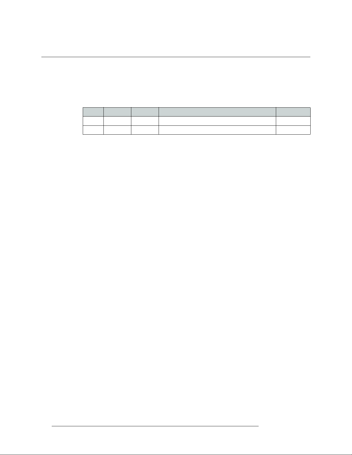
Change History
The table below lists the changes to the iMC-Panel-200 Operator’s Guide (for Imagestore 750).
• Part # UG0069-00
• Software version: 7.2.0.0
Rev Date ECO Description Approved By
1.0 29 Nov 11 17941 New document. D.Cox
iv Rev 1.0 • 29 Nov 11
Page 5
Important Safeguards and Notices
This section provides important safety guidelines for operators and service personnel. Specific
warnings and cautions appear throughout the manual where they apply. Please read and follow this
important information, especially those instructions related to the risk of electric shock or injury to
persons.
Warning
Any instructions in this manual that require opening the equipment cover or
enclosure are for use by qualified service personnel only. To reduce the risk of
electric shock, do not perform any service other than that contained in the
operating instructions unless you are qualified to do so.
Symbols and Their Meanings
The lightning flash with arrowhead symbol within an equilateral triangle alerts the user to the presence of dangerous voltages within the product’s enclosure that may be of sufficient magnitude to
constitute a risk of electric shock to persons.
The exclamation point within an equilateral triangle alerts the user to the presence of important
operating and maintenance/service instructions.
The Ground symbol represents a protective grounding terminal. Such a terminal must be connected
to earth ground prior to making any other connections to the equipment.
The fuse symbol indicates that the fuse referenced in the text must be replaced with one having the
ratings indicated.
The presence of this symbol in or on Miranda equipment means that it has been designed, tested
and certified as complying with applicable Underwriter’s Laboratory (USA) regulations and recommendations.
The presence of this symbol in or on Miranda equipment means that it has been designed, tested
and certified as essentially complying with all applicable European Union (CE) regulations and
recommendations.
Master Control • iMC-Panel-100 Operator’s Guide v
Page 6

General Warnings
A warning indicates a possible hazard to personnel which may cause injury or death. Observe the
following general warnings when using or working on this equipment:
• Heed all warnings on the unit and in the operating instructions.
• Do not use this equipment in or near water.
• This equipment is grounded through the grounding conductor of the power cord. To avoid electrical shock, plug the power cord into a properly wired receptacle before connecting the equipment inputs or outputs.
• Route power cords and other cables so they are not likely to be damaged.
• Disconnect power before cleaning the equipment. Do not use liquid or aerosol cleaners; use
only a damp cloth.
• Dangerous voltages may exist at several points in this equipment. To avoid injury, do not touch
exposed connections and components while power is on.
• Do not wear rings or wristwatches when troubleshooting high current circuits such as the power
supplies.
• To avoid fire hazard, use only the specified fuse(s) with the correct type number, voltage and
current ratings as referenced in the appropriate locations in the service instructions or on the
equipment. Always refer fuse replacements to qualified service personnel.
• To avoid explosion, do not operate this equipment in an explosive atmosphere.
• Have qualified service personnel perform safety checks after any service.
General Cautions
A caution indicates a possible hazard to equipment that could result in equipment damage. Observe
the following cautions when operating or working on this equipment:
• When installing this equipment, do not attach the power cord to building surfaces.
• To prevent damage to equipment when replacing fuses, locate and correct the problem that
caused the fuse to blow before re-applying power.
• Use only the specified replacement parts.
• Follow static precautions at all times when handling this equipment.
• This product should only be powered as described in the manual. To prevent equipment damage, select the proper line voltage on the power supply(ies) as described in the installation documentation.
• To prevent damage to the equipment, read the instructions in the equipment manual for proper
input voltage range selection.
• Some products include a backup battery. There is a risk of explosion if the battery is replaced by
a battery of an incorrect type. Dispose of batteries according to instructions.
• Products that have (1) no on/off switch and (2) use an external power supply must be installed
in proximity to a main power output that is easily accessible.
vi Rev 1.0 • 29 Nov 11
Page 7

Table of Contents
Chapter 1 Preface . . . . . . . . . . . . . . . . . . . . . . . . . . . . . . . . . . . . . . . . . . . . . . . . . . . . . . . . . . . . . . . . . . . 1
Chapter Structure . . . . . . . . . . . . . . . . . . . . . . . . . . . . . . . . . . . . . . . . . . . . . . . . . . . . . . . . . . . . . . 1
The PDF Document . . . . . . . . . . . . . . . . . . . . . . . . . . . . . . . . . . . . . . . . . . . . . . . . . . . . . . . . . . . . 1
Terms, Conventions and Abbreviations . . . . . . . . . . . . . . . . . . . . . . . . . . . . . . . . . . . . . . . . . . . . . 2
Prerequisites . . . . . . . . . . . . . . . . . . . . . . . . . . . . . . . . . . . . . . . . . . . . . . . . . . . . . . . . . . . . . . . . . . 3
Options . . . . . . . . . . . . . . . . . . . . . . . . . . . . . . . . . . . . . . . . . . . . . . . . . . . . . . . . . . . . . . . . . . . . . . . 3
Chapter 2 Introduction . . . . . . . . . . . . . . . . . . . . . . . . . . . . . . . . . . . . . . . . . . . . . . . . . . . . . . . . . . . . . . 5
Purpose. . . . . . . . . . . . . . . . . . . . . . . . . . . . . . . . . . . . . . . . . . . . . . . . . . . . . . . . . . . . . . . . . . . . . . . 5
Master Control System Overview . . . . . . . . . . . . . . . . . . . . . . . . . . . . . . . . . . . . . . . . . . . . . . . . . . 5
NV9000 Router Control System . . . . . . . . . . . . . . . . . . . . . . . . . . . . . . . . . . . . . . . . . . . . . . . 6
Control Panels . . . . . . . . . . . . . . . . . . . . . . . . . . . . . . . . . . . . . . . . . . . . . . . . . . . . . . . . . . . . . 7
Other Miranda Products . . . . . . . . . . . . . . . . . . . . . . . . . . . . . . . . . . . . . . . . . . . . . . . . . . . . . . 7
Tally Processor. . . . . . . . . . . . . . . . . . . . . . . . . . . . . . . . . . . . . . . . . . . . . . . . . . . . . . . . . 7
Intuition XG . . . . . . . . . . . . . . . . . . . . . . . . . . . . . . . . . . . . . . . . . . . . . . . . . . . . . . . . . . . 7
Imagestore 750 Overview . . . . . . . . . . . . . . . . . . . . . . . . . . . . . . . . . . . . . . . . . . . . . . . . . . . . . . . . 7
Conceptual Model . . . . . . . . . . . . . . . . . . . . . . . . . . . . . . . . . . . . . . . . . . . . . . . . . . . . . . . . . . 9
Detailed Model. . . . . . . . . . . . . . . . . . . . . . . . . . . . . . . . . . . . . . . . . . . . . . . . . . . . . . . . . . . . 10
Control Panel Features . . . . . . . . . . . . . . . . . . . . . . . . . . . . . . . . . . . . . . . . . . . . . . . . . . . . . . . . . 11
Chapter 3 Control Panel . . . . . . . . . . . . . . . . . . . . . . . . . . . . . . . . . . . . . . . . . . . . . . . . . . . . . . . . . . . .13
Panel Summary . . . . . . . . . . . . . . . . . . . . . . . . . . . . . . . . . . . . . . . . . . . . . . . . . . . . . . . . . . . . . . . 13
Button Panel . . . . . . . . . . . . . . . . . . . . . . . . . . . . . . . . . . . . . . . . . . . . . . . . . . . . . . . . . . . . . . 13
Display Unit . . . . . . . . . . . . . . . . . . . . . . . . . . . . . . . . . . . . . . . . . . . . . . . . . . . . . . . . . . . . . . 14
Panel Buttons . . . . . . . . . . . . . . . . . . . . . . . . . . . . . . . . . . . . . . . . . . . . . . . . . . . . . . . . . . . . 15
Soft buttons . . . . . . . . . . . . . . . . . . . . . . . . . . . . . . . . . . . . . . . . . . . . . . . . . . . . . . . . . . 16
Panel Knobs . . . . . . . . . . . . . . . . . . . . . . . . . . . . . . . . . . . . . . . . . . . . . . . . . . . . . . . . . . 16
Functional Sections of the Panel . . . . . . . . . . . . . . . . . . . . . . . . . . . . . . . . . . . . . . . . . . . . . . . . . . 17
Top Row Buttons . . . . . . . . . . . . . . . . . . . . . . . . . . . . . . . . . . . . . . . . . . . . . . . . . . . . . . . . . . 20
Menu Area . . . . . . . . . . . . . . . . . . . . . . . . . . . . . . . . . . . . . . . . . . . . . . . . . . . . . . . . . . . . . . . 21
Configurable Button Section . . . . . . . . . . . . . . . . . . . . . . . . . . . . . . . . . . . . . . . . . . . . . . . . . 22
Audio Levels . . . . . . . . . . . . . . . . . . . . . . . . . . . . . . . . . . . . . . . . . . . . . . . . . . . . . . . . . . . . . 23
‘Program Out’ Knob . . . . . . . . . . . . . . . . . . . . . . . . . . . . . . . . . . . . . . . . . . . . . . . . . . . 23
‘Preset In’ Knob . . . . . . . . . . . . . . . . . . . . . . . . . . . . . . . . . . . . . . . . . . . . . . . . . . . . . . . 23
‘Over Ratio/Duck Level’ Knob . . . . . . . . . . . . . . . . . . . . . . . . . . . . . . . . . . . . . . . . . . . 23
On-Screen “Knobs” and the Slider . . . . . . . . . . . . . . . . . . . . . . . . . . . . . . . . . . . . . . . . . . . . 24
Audio Monitoring . . . . . . . . . . . . . . . . . . . . . . . . . . . . . . . . . . . . . . . . . . . . . . . . . . . . . . . . . 24
Preset and Program Buttons . . . . . . . . . . . . . . . . . . . . . . . . . . . . . . . . . . . . . . . . . . . . . . . . . 25
Aux/User and Preview/User Buttons . . . . . . . . . . . . . . . . . . . . . . . . . . . . . . . . . . . . . . . . . . 26
Button Details . . . . . . . . . . . . . . . . . . . . . . . . . . . . . . . . . . . . . . . . . . . . . . . . . . . . . . . . . . . . 27
Source Button Characteristics . . . . . . . . . . . . . . . . . . . . . . . . . . . . . . . . . . . . . . . . . . . . 27
“Hot Cuts” . . . . . . . . . . . . . . . . . . . . . . . . . . . . . . . . . . . . . . . . . . . . . . . . . . . . . . . . . . . 27
Video Effects . . . . . . . . . . . . . . . . . . . . . . . . . . . . . . . . . . . . . . . . . . . . . . . . . . . . . . . . . 27
Voice-Overs . . . . . . . . . . . . . . . . . . . . . . . . . . . . . . . . . . . . . . . . . . . . . . . . . . . . . . . . . . 29
Bottom Row Buttons . . . . . . . . . . . . . . . . . . . . . . . . . . . . . . . . . . . . . . . . . . . . . . . . . . . . . . . 29
Transition Button . . . . . . . . . . . . . . . . . . . . . . . . . . . . . . . . . . . . . . . . . . . . . . . . . . . . . . . . . 30
Master Control • iMC-Panel-100 Operator’s Guide vii
Page 8

Table of Contents
Definable Button Functions . . . . . . . . . . . . . . . . . . . . . . . . . . . . . . . . . . . . . . . . . . . . . . . . . . . . . . 30
None . . . . . . . . . . . . . . . . . . . . . . . . . . . . . . . . . . . . . . . . . . . . . . . . . . . . . . . . . . . . . . . . . . . 30
Channel Selection . . . . . . . . . . . . . . . . . . . . . . . . . . . . . . . . . . . . . . . . . . . . . . . . . . . . . . . . . 30
Channel Select . . . . . . . . . . . . . . . . . . . . . . . . . . . . . . . . . . . . . . . . . . . . . . . . . . . . . . . . 31
No Channels . . . . . . . . . . . . . . . . . . . . . . . . . . . . . . . . . . . . . . . . . . . . . . . . . . . . . . . . . . 31
Salvo . . . . . . . . . . . . . . . . . . . . . . . . . . . . . . . . . . . . . . . . . . . . . . . . . . . . . . . . . . . . . . . . . . . 32
System Control . . . . . . . . . . . . . . . . . . . . . . . . . . . . . . . . . . . . . . . . . . . . . . . . . . . . . . . . . . . 32
Panel Lock . . . . . . . . . . . . . . . . . . . . . . . . . . . . . . . . . . . . . . . . . . . . . . . . . . . . . . . . . . . 32
Automation Off . . . . . . . . . . . . . . . . . . . . . . . . . . . . . . . . . . . . . . . . . . . . . . . . . . . . . . . 32
Fade to Black . . . . . . . . . . . . . . . . . . . . . . . . . . . . . . . . . . . . . . . . . . . . . . . . . . . . . . . . 32
Fade to Silence . . . . . . . . . . . . . . . . . . . . . . . . . . . . . . . . . . . . . . . . . . . . . . . . . . . . . . . 33
Group Select . . . . . . . . . . . . . . . . . . . . . . . . . . . . . . . . . . . . . . . . . . . . . . . . . . . . . . . . . 33
Audio Lock . . . . . . . . . . . . . . . . . . . . . . . . . . . . . . . . . . . . . . . . . . . . . . . . . . . . . . . . . . 33
Macro Arm . . . . . . . . . . . . . . . . . . . . . . . . . . . . . . . . . . . . . . . . . . . . . . . . . . . . . . . . . . 33
Fire Macro . . . . . . . . . . . . . . . . . . . . . . . . . . . . . . . . . . . . . . . . . . . . . . . . . . . . . . . . . . . 33
PGM DVE Enable . . . . . . . . . . . . . . . . . . . . . . . . . . . . . . . . . . . . . . . . . . . . . . . . . . . . . 33
PST DVE Enable . . . . . . . . . . . . . . . . . . . . . . . . . . . . . . . . . . . . . . . . . . . . . . . . . . . . . 34
KaleidoX Layout . . . . . . . . . . . . . . . . . . . . . . . . . . . . . . . . . . . . . . . . . . . . . . . . . . . . . . 34
Menu . . . . . . . . . . . . . . . . . . . . . . . . . . . . . . . . . . . . . . . . . . . . . . . . . . . . . . . . . . . . . . . . . . . 34
Automation Assist . . . . . . . . . . . . . . . . . . . . . . . . . . . . . . . . . . . . . . . . . . . . . . . . . . . . . . . . . 34
Transition Type . . . . . . . . . . . . . . . . . . . . . . . . . . . . . . . . . . . . . . . . . . . . . . . . . . . . . . . . . . . 34
Transition Rate . . . . . . . . . . . . . . . . . . . . . . . . . . . . . . . . . . . . . . . . . . . . . . . . . . . . . . . . . . . 35
Notes . . . . . . . . . . . . . . . . . . . . . . . . . . . . . . . . . . . . . . . . . . . . . . . . . . . . . . . . . . . . . . . . . . . 36
Connectors . . . . . . . . . . . . . . . . . . . . . . . . . . . . . . . . . . . . . . . . . . . . . . . . . . . . . . . . . . . . . . . . . . 36
Button Panel . . . . . . . . . . . . . . . . . . . . . . . . . . . . . . . . . . . . . . . . . . . . . . . . . . . . . . . . . . . . . . 36
Power . . . . . . . . . . . . . . . . . . . . . . . . . . . . . . . . . . . . . . . . . . . . . . . . . . . . . . . . . . . . . . . 36
Ethernet . . . . . . . . . . . . . . . . . . . . . . . . . . . . . . . . . . . . . . . . . . . . . . . . . . . . . . . . . . . . . 37
USB Ports. . . . . . . . . . . . . . . . . . . . . . . . . . . . . . . . . . . . . . . . . . . . . . . . . . . . . . . . . . . . 37
VGA Port . . . . . . . . . . . . . . . . . . . . . . . . . . . . . . . . . . . . . . . . . . . . . . . . . . . . . . . . . . . . 37
GPI/Alarm . . . . . . . . . . . . . . . . . . . . . . . . . . . . . . . . . . . . . . . . . . . . . . . . . . . . . . . . . . . 37
Touchscreen Display . . . . . . . . . . . . . . . . . . . . . . . . . . . . . . . . . . . . . . . . . . . . . . . . . . . . . . . 38
Chapter 4 Installation . . . . . . . . . . . . . . . . . . . . . . . . . . . . . . . . . . . . . . . . . . . . . . . . . . . . . . . . . . . . . . . 39
Summary . . . . . . . . . . . . . . . . . . . . . . . . . . . . . . . . . . . . . . . . . . . . . . . . . . . . . . . . . . . . . . . . . . . . 39
Button Panel . . . . . . . . . . . . . . . . . . . . . . . . . . . . . . . . . . . . . . . . . . . . . . . . . . . . . . . . . . . . . . . . . . 40
Display . . . . . . . . . . . . . . . . . . . . . . . . . . . . . . . . . . . . . . . . . . . . . . . . . . . . . . . . . . . . . . . . . . . . . . 41
Mounting the display . . . . . . . . . . . . . . . . . . . . . . . . . . . . . . . . . . . . . . . . . . . . . . . . . . . . . . . 41
Connections . . . . . . . . . . . . . . . . . . . . . . . . . . . . . . . . . . . . . . . . . . . . . . . . . . . . . . . . . . . . . . . . . . 42
/ Alarms . . . . . . . . . . . . . . . . . . . . . . . . . . . . . . . . . . . . . . . . . . . . . . . . . . . . . . . . . . . . . . 42
GPI
Cabling . . . . . . . . . . . . . . . . . . . . . . . . . . . . . . . . . . . . . . . . . . . . . . . . . . . . . . . . . . . . . . . . . . 43
Setup. . . . . . . . . . . . . . . . . . . . . . . . . . . . . . . . . . . . . . . . . . . . . . . . . . . . . . . . . . . . . . . . . . . . 44
Chapter 5 Menus . . . . . . . . . . . . . . . . . . . . . . . . . . . . . . . . . . . . . . . . . . . . . . . . . . . . . . . . . . . . . . . . . . . 45
About Menus . . . . . . . . . . . . . . . . . . . . . . . . . . . . . . . . . . . . . . . . . . . . . . . . . . . . . . . . . . . . . . . . . 45
Main Menu . . . . . . . . . . . . . . . . . . . . . . . . . . . . . . . . . . . . . . . . . . . . . . . . . . . . . . . . . . . . . . . 46
Other Menus. . . . . . . . . . . . . . . . . . . . . . . . . . . . . . . . . . . . . . . . . . . . . . . . . . . . . . . . . . . . . . 47
Menu Button Conventions . . . . . . . . . . . . . . . . . . . . . . . . . . . . . . . . . . . . . . . . . . . . . . . . . . . 49
Keypads . . . . . . . . . . . . . . . . . . . . . . . . . . . . . . . . . . . . . . . . . . . . . . . . . . . . . . . . . . . . . . . . . 49
Lists . . . . . . . . . . . . . . . . . . . . . . . . . . . . . . . . . . . . . . . . . . . . . . . . . . . . . . . . . . . . . . . . . . . . 50
Main Menu . . . . . . . . . . . . . . . . . . . . . . . . . . . . . . . . . . . . . . . . . . . . . . . . . . . . . . . . . . . . . . . . . . . 51
Audio Meters Menu . . . . . . . . . . . . . . . . . . . . . . . . . . . . . . . . . . . . . . . . . . . . . . . . . . . . . . . . . . . . 53
Audio Preview Menu . . . . . . . . . . . . . . . . . . . . . . . . . . . . . . . . . . . . . . . . . . . . . . . . . . . . . . . . . . . 55
Automation Menu . . . . . . . . . . . . . . . . . . . . . . . . . . . . . . . . . . . . . . . . . . . . . . . . . . . . . . . . . . . . . 56
Buttons . . . . . . . . . . . . . . . . . . . . . . . . . . . . . . . . . . . . . . . . . . . . . . . . . . . . . . . . . . . . . . . . . . 56
viii Rev 1.0 • 28 Nov 11
Page 9

Table of Contents
Channel Select Menu . . . . . . . . . . . . . . . . . . . . . . . . . . . . . . . . . . . . . . . . . . . . . . . . . . . . . . . . . . . 57
Sharing Channels . . . . . . . . . . . . . . . . . . . . . . . . . . . . . . . . . . . . . . . . . . . . . . . . . . . . . . . . . . 58
Preemption . . . . . . . . . . . . . . . . . . . . . . . . . . . . . . . . . . . . . . . . . . . . . . . . . . . . . . . . . . . 58
Sharing . . . . . . . . . . . . . . . . . . . . . . . . . . . . . . . . . . . . . . . . . . . . . . . . . . . . . . . . . . . . . . 58
Edit/More . . . . . . . . . . . . . . . . . . . . . . . . . . . . . . . . . . . . . . . . . . . . . . . . . . . . . . . . . . . . . . . . 59
Channel Details Sub-Menu . . . . . . . . . . . . . . . . . . . . . . . . . . . . . . . . . . . . . . . . . . . . . . . . . . 59
Version Info Sub-Menu . . . . . . . . . . . . . . . . . . . . . . . . . . . . . . . . . . . . . . . . . . . . . . . . . 60
DSK Menus . . . . . . . . . . . . . . . . . . . . . . . . . . . . . . . . . . . . . . . . . . . . . . . . . . . . . . . . . . . . . . . . . . 61
Options Buttons . . . . . . . . . . . . . . . . . . . . . . . . . . . . . . . . . . . . . . . . . . . . . . . . . . . . . . . . . . . 62
List Buttons . . . . . . . . . . . . . . . . . . . . . . . . . . . . . . . . . . . . . . . . . . . . . . . . . . . . . . . . . . . . . . 62
Rates, CGT, Keying . . . . . . . . . . . . . . . . . . . . . . . . . . . . . . . . . . . . . . . . . . . . . . . . . . . . 62
Position, Size, Crop . . . . . . . . . . . . . . . . . . . . . . . . . . . . . . . . . . . . . . . . . . . . . . . . . . . . 64
‘Options Saving’ . . . . . . . . . . . . . . . . . . . . . . . . . . . . . . . . . . . . . . . . . . . . . . . . . . . . . . 65
“EasyPlay” Menus . . . . . . . . . . . . . . . . . . . . . . . . . . . . . . . . . . . . . . . . . . . . . . . . . . . . . . . . . . . . . 66
Macro Menu . . . . . . . . . . . . . . . . . . . . . . . . . . . . . . . . . . . . . . . . . . . . . . . . . . . . . . . . . . . . . . . . . . 67
Program Input Audio Menu . . . . . . . . . . . . . . . . . . . . . . . . . . . . . . . . . . . . . . . . . . . . . . . . . . . . . . 68
Buttons . . . . . . . . . . . . . . . . . . . . . . . . . . . . . . . . . . . . . . . . . . . . . . . . . . . . . . . . . . . . . . . . . . 68
Gains and Mutes. . . . . . . . . . . . . . . . . . . . . . . . . . . . . . . . . . . . . . . . . . . . . . . . . . . . . . . . . . . 69
“Phase Inverts”. . . . . . . . . . . . . . . . . . . . . . . . . . . . . . . . . . . . . . . . . . . . . . . . . . . . . . . . . . . . 70
Audio Channel Shuffle. . . . . . . . . . . . . . . . . . . . . . . . . . . . . . . . . . . . . . . . . . . . . . . . . . . . . . 71
Program Output Audio Menu . . . . . . . . . . . . . . . . . . . . . . . . . . . . . . . . . . . . . . . . . . . . . . . . . . . . 72
Buttons . . . . . . . . . . . . . . . . . . . . . . . . . . . . . . . . . . . . . . . . . . . . . . . . . . . . . . . . . . . . . . . . . . 72
Gains and Mutes. . . . . . . . . . . . . . . . . . . . . . . . . . . . . . . . . . . . . . . . . . . . . . . . . . . . . . . . . . . 73
“Phase Inverts”. . . . . . . . . . . . . . . . . . . . . . . . . . . . . . . . . . . . . . . . . . . . . . . . . . . . . . . . . . . . 74
Preset Input Audio Menu . . . . . . . . . . . . . . . . . . . . . . . . . . . . . . . . . . . . . . . . . . . . . . . . . . . . . . . . 75
Buttons . . . . . . . . . . . . . . . . . . . . . . . . . . . . . . . . . . . . . . . . . . . . . . . . . . . . . . . . . . . . . . . . . . 75
Gains and Mutes. . . . . . . . . . . . . . . . . . . . . . . . . . . . . . . . . . . . . . . . . . . . . . . . . . . . . . . . . . . 76
“Phase Inverts”. . . . . . . . . . . . . . . . . . . . . . . . . . . . . . . . . . . . . . . . . . . . . . . . . . . . . . . . . . . . 77
Audio Channel Shuffle. . . . . . . . . . . . . . . . . . . . . . . . . . . . . . . . . . . . . . . . . . . . . . . . . . . . . . 78
Voice-Over Menus . . . . . . . . . . . . . . . . . . . . . . . . . . . . . . . . . . . . . . . . . . . . . . . . . . . . . . . . . . . . . 79
Buttons . . . . . . . . . . . . . . . . . . . . . . . . . . . . . . . . . . . . . . . . . . . . . . . . . . . . . . . . . . . . . . . . . . 79
Gains and Mutes. . . . . . . . . . . . . . . . . . . . . . . . . . . . . . . . . . . . . . . . . . . . . . . . . . . . . . . . . . . 80
Phase Inverts . . . . . . . . . . . . . . . . . . . . . . . . . . . . . . . . . . . . . . . . . . . . . . . . . . . . . . . . . . . . . 81
Audio Channel Shuffle. . . . . . . . . . . . . . . . . . . . . . . . . . . . . . . . . . . . . . . . . . . . . . . . . . . . . . 82
XG Keyer Layers Menu . . . . . . . . . . . . . . . . . . . . . . . . . . . . . . . . . . . . . . . . . . . . . . . . . . . . . . . . . 83
XG Layer Menus . . . . . . . . . . . . . . . . . . . . . . . . . . . . . . . . . . . . . . . . . . . . . . . . . . . . . . . . . . 84
A/B Mixer Menu . . . . . . . . . . . . . . . . . . . . . . . . . . . . . . . . . . . . . . . . . . . . . . . . . . . . . . . . . . . . . . 85
Adjust Profiles . . . . . . . . . . . . . . . . . . . . . . . . . . . . . . . . . . . . . . . . . . . . . . . . . . . . . . . . . . . . 86
Sources Menu. . . . . . . . . . . . . . . . . . . . . . . . . . . . . . . . . . . . . . . . . . . . . . . . . . . . . . . . . . . . . . . . . 87
Adding a Source to a Group. . . . . . . . . . . . . . . . . . . . . . . . . . . . . . . . . . . . . . . . . . . . . . . . . . 88
Changing a Source within a Group . . . . . . . . . . . . . . . . . . . . . . . . . . . . . . . . . . . . . . . . . . . . 89
Removing a Source from a Group . . . . . . . . . . . . . . . . . . . . . . . . . . . . . . . . . . . . . . . . . . . . . 90
Panel Menu . . . . . . . . . . . . . . . . . . . . . . . . . . . . . . . . . . . . . . . . . . . . . . . . . . . . . . . . . . . . . . . . . . 91
IP Setup . . . . . . . . . . . . . . . . . . . . . . . . . . . . . . . . . . . . . . . . . . . . . . . . . . . . . . . . . . . . . . . . . 92
Manage Log . . . . . . . . . . . . . . . . . . . . . . . . . . . . . . . . . . . . . . . . . . . . . . . . . . . . . . . . . . . . . . 93
Set Date Time. . . . . . . . . . . . . . . . . . . . . . . . . . . . . . . . . . . . . . . . . . . . . . . . . . . . . . . . . . . . . 94
Version Info . . . . . . . . . . . . . . . . . . . . . . . . . . . . . . . . . . . . . . . . . . . . . . . . . . . . . . . . . . . . . . 95
Panel Status . . . . . . . . . . . . . . . . . . . . . . . . . . . . . . . . . . . . . . . . . . . . . . . . . . . . . . . . . . . . . . 95
Panel Test Sub-Menu . . . . . . . . . . . . . . . . . . . . . . . . . . . . . . . . . . . . . . . . . . . . . . . . . . . 96
Master Control • iMC-Panel-100 Operator’s Guide ix
Page 10

Table of Contents
Chapter 6 Operation . . . . . . . . . . . . . . . . . . . . . . . . . . . . . . . . . . . . . . . . . . . . . . . . . . . . . . . . . . . . . . .99
General Information . . . . . . . . . . . . . . . . . . . . . . . . . . . . . . . . . . . . . . . . . . . . . . . . . . . . . . . . . . . . 99
About Colors . . . . . . . . . . . . . . . . . . . . . . . . . . . . . . . . . . . . . . . . . . . . . . . . . . . . . . . . . . . . . 99
Colors on Physical LCD Buttons . . . . . . . . . . . . . . . . . . . . . . . . . . . . . . . . . . . . . . . . . 100
Colors on “Soft” Buttons . . . . . . . . . . . . . . . . . . . . . . . . . . . . . . . . . . . . . . . . . . . . . . . 101
Button Colors in the Menu Area . . . . . . . . . . . . . . . . . . . . . . . . . . . . . . . . . . . . . . . . . 102
Thumbnail Color . . . . . . . . . . . . . . . . . . . . . . . . . . . . . . . . . . . . . . . . . . . . . . . . . . . . . 103
About Error Messages . . . . . . . . . . . . . . . . . . . . . . . . . . . . . . . . . . . . . . . . . . . . . . . . . . . . . 103
About the Button Rows . . . . . . . . . . . . . . . . . . . . . . . . . . . . . . . . . . . . . . . . . . . . . . . . . . . . 104
About “Layer” Buttons . . . . . . . . . . . . . . . . . . . . . . . . . . . . . . . . . . . . . . . . . . . . . . . . . . . . 104
About Configurable Buttons . . . . . . . . . . . . . . . . . . . . . . . . . . . . . . . . . . . . . . . . . . . . . . . . 104
Panels and Channels. . . . . . . . . . . . . . . . . . . . . . . . . . . . . . . . . . . . . . . . . . . . . . . . . . . . . . . 104
Sharing vs. Preemption . . . . . . . . . . . . . . . . . . . . . . . . . . . . . . . . . . . . . . . . . . . . . . . . . . . . 105
Using the Keypad. . . . . . . . . . . . . . . . . . . . . . . . . . . . . . . . . . . . . . . . . . . . . . . . . . . . . . . . . 105
Performing Transitions . . . . . . . . . . . . . . . . . . . . . . . . . . . . . . . . . . . . . . . . . . . . . . . . . . . . . . . . 106
Basic Transition . . . . . . . . . . . . . . . . . . . . . . . . . . . . . . . . . . . . . . . . . . . . . . . . . . . . . . . . . . 106
Transition Options . . . . . . . . . . . . . . . . . . . . . . . . . . . . . . . . . . . . . . . . . . . . . . . . . . . . . . . . . . . . 107
Working with Transition Type and Rate . . . . . . . . . . . . . . . . . . . . . . . . . . . . . . . . . . . . . . . . . . . 108
Notes . . . . . . . . . . . . . . . . . . . . . . . . . . . . . . . . . . . . . . . . . . . . . . . . . . . . . . . . . . . . . . . . . . 109
Changing Transition Rates . . . . . . . . . . . . . . . . . . . . . . . . . . . . . . . . . . . . . . . . . . . . . . . . . 109
Working with DSKs . . . . . . . . . . . . . . . . . . . . . . . . . . . . . . . . . . . . . . . . . . . . . . . . . . . . . . . . . . 109
Performing Key Transitions . . . . . . . . . . . . . . . . . . . . . . . . . . . . . . . . . . . . . . . . . . . . . . . . . 110
Changing Key Settings . . . . . . . . . . . . . . . . . . . . . . . . . . . . . . . . . . . . . . . . . . . . . . . . . . . . 110
Rates, CGT, Keying . . . . . . . . . . . . . . . . . . . . . . . . . . . . . . . . . . . . . . . . . . . . . . . . . . . 111
Position, Size, and Crop . . . . . . . . . . . . . . . . . . . . . . . . . . . . . . . . . . . . . . . . . . . . . . . . 113
Saving DSK Settings . . . . . . . . . . . . . . . . . . . . . . . . . . . . . . . . . . . . . . . . . . . . . . . . . . 114
Working with DVEs . . . . . . . . . . . . . . . . . . . . . . . . . . . . . . . . . . . . . . . . . . . . . . . . . . . . . . . . . . 115
Working with XG Layers . . . . . . . . . . . . . . . . . . . . . . . . . . . . . . . . . . . . . . . . . . . . . . . . . . . . . . 115
Working with Voice-Overs . . . . . . . . . . . . . . . . . . . . . . . . . . . . . . . . . . . . . . . . . . . . . . . . . . . . . 116
Performing Transitions with Voice-Over . . . . . . . . . . . . . . . . . . . . . . . . . . . . . . . . . . . . . . 116
Voice-Over Menu . . . . . . . . . . . . . . . . . . . . . . . . . . . . . . . . . . . . . . . . . . . . . . . . . . . . . . . . 117
Gains and Mutes. . . . . . . . . . . . . . . . . . . . . . . . . . . . . . . . . . . . . . . . . . . . . . . . . . . . . . . . . . 118
“Phase Inverts”. . . . . . . . . . . . . . . . . . . . . . . . . . . . . . . . . . . . . . . . . . . . . . . . . . . . . . . . . . . 119
Audio Channel Shuffle. . . . . . . . . . . . . . . . . . . . . . . . . . . . . . . . . . . . . . . . . . . . . . . . . . . . . 120
Performing Over Transitions . . . . . . . . . . . . . . . . . . . . . . . . . . . . . . . . . . . . . . . . . . . . . . . . 120
Working with Audio Monitors . . . . . . . . . . . . . . . . . . . . . . . . . . . . . . . . . . . . . . . . . . . . . . . . . . 121
Audio Preview Menu . . . . . . . . . . . . . . . . . . . . . . . . . . . . . . . . . . . . . . . . . . . . . . . . . . . . . . 122
Working with Audio Meters . . . . . . . . . . . . . . . . . . . . . . . . . . . . . . . . . . . . . . . . . . . . . . . . . . . . 123
Working with Audio Levels . . . . . . . . . . . . . . . . . . . . . . . . . . . . . . . . . . . . . . . . . . . . . . . . . . . . 124
‘Program Out’ Knob . . . . . . . . . . . . . . . . . . . . . . . . . . . . . . . . . . . . . . . . . . . . . . . . . . 124
‘Preset In’ Knob . . . . . . . . . . . . . . . . . . . . . . . . . . . . . . . . . . . . . . . . . . . . . . . . . . . . . 124
‘Over Ratio/Duck Level’ Knob . . . . . . . . . . . . . . . . . . . . . . . . . . . . . . . . . . . . . . . . . . 125
Menus. . . . . . . . . . . . . . . . . . . . . . . . . . . . . . . . . . . . . . . . . . . . . . . . . . . . . . . . . . . . . . . . . . 125
Gains and Mutes. . . . . . . . . . . . . . . . . . . . . . . . . . . . . . . . . . . . . . . . . . . . . . . . . . . . . . . . . . 127
Phase Inverts . . . . . . . . . . . . . . . . . . . . . . . . . . . . . . . . . . . . . . . . . . . . . . . . . . . . . . . . . . . . 128
Audio Channel Shuffle. . . . . . . . . . . . . . . . . . . . . . . . . . . . . . . . . . . . . . . . . . . . . . . . . . . . . 129
Shuffling Audio Channels . . . . . . . . . . . . . . . . . . . . . . . . . . . . . . . . . . . . . . . . . . . . . . . . . . . . . . 129
Performing a Shuffle . . . . . . . . . . . . . . . . . . . . . . . . . . . . . . . . . . . . . . . . . . . . . . . . . . . . . . 129
Working with Multiple Channels . . . . . . . . . . . . . . . . . . . . . . . . . . . . . . . . . . . . . . . . . . . . . . . . 131
Automatic Gang Mode. . . . . . . . . . . . . . . . . . . . . . . . . . . . . . . . . . . . . . . . . . . . . . . . . . . . . 131
Channel Selection with Buttons . . . . . . . . . . . . . . . . . . . . . . . . . . . . . . . . . . . . . . . . . . . . . 132
Channel Selection in the Menus . . . . . . . . . . . . . . . . . . . . . . . . . . . . . . . . . . . . . . . . . . . . . 132
No Channel Selection. . . . . . . . . . . . . . . . . . . . . . . . . . . . . . . . . . . . . . . . . . . . . . . . . . . . . . 132
Sharing Channels . . . . . . . . . . . . . . . . . . . . . . . . . . . . . . . . . . . . . . . . . . . . . . . . . . . . . . . . . 132
Preemption . . . . . . . . . . . . . . . . . . . . . . . . . . . . . . . . . . . . . . . . . . . . . . . . . . . . . . . . . . 133
Sharing . . . . . . . . . . . . . . . . . . . . . . . . . . . . . . . . . . . . . . . . . . . . . . . . . . . . . . . . . . . . . . . . . 133
Monitor Wall Re-Layout . . . . . . . . . . . . . . . . . . . . . . . . . . . . . . . . . . . . . . . . . . . . . . . . . . . 133
x Rev 1.0 • 28 Nov 11
Page 11

Table of Contents
Working with a Monitor Wall . . . . . . . . . . . . . . . . . . . . . . . . . . . . . . . . . . . . . . . . . . . . . . . . . . . 134
Working with the Aux Buttons . . . . . . . . . . . . . . . . . . . . . . . . . . . . . . . . . . . . . . . . . . . . . . . . . . 134
‘Aux Bus Follow’. . . . . . . . . . . . . . . . . . . . . . . . . . . . . . . . . . . . . . . . . . . . . . . . . . . . . . . . . 134
Using the Panel Menu . . . . . . . . . . . . . . . . . . . . . . . . . . . . . . . . . . . . . . . . . . . . . . . . . . . . . . . . . 135
Panel Status . . . . . . . . . . . . . . . . . . . . . . . . . . . . . . . . . . . . . . . . . . . . . . . . . . . . . . . . . . . . . 136
IP Address . . . . . . . . . . . . . . . . . . . . . . . . . . . . . . . . . . . . . . . . . . . . . . . . . . . . . . . . . . . . . . 137
View Version Information . . . . . . . . . . . . . . . . . . . . . . . . . . . . . . . . . . . . . . . . . . . . . . . . . . 138
View or Clear the Panel’s Log File . . . . . . . . . . . . . . . . . . . . . . . . . . . . . . . . . . . . . . . . . . . 138
Set Time and Date . . . . . . . . . . . . . . . . . . . . . . . . . . . . . . . . . . . . . . . . . . . . . . . . . . . . . . . . 139
Fade to Black . . . . . . . . . . . . . . . . . . . . . . . . . . . . . . . . . . . . . . . . . . . . . . . . . . . . . . . . . . . . . . . 140
Fade to Silence . . . . . . . . . . . . . . . . . . . . . . . . . . . . . . . . . . . . . . . . . . . . . . . . . . . . . . . . . . . . . . 140
Updating Configuration Settings . . . . . . . . . . . . . . . . . . . . . . . . . . . . . . . . . . . . . . . . . . . . . . . . 140
Panel Startup and Shutdown . . . . . . . . . . . . . . . . . . . . . . . . . . . . . . . . . . . . . . . . . . . . . . . . . . . . 141
Chapter 7 Misc. Topics . . . . . . . . . . . . . . . . . . . . . . . . . . . . . . . . . . . . . . . . . . . . . . . . . . . . . . . . . . . . .143
Glossary . . . . . . . . . . . . . . . . . . . . . . . . . . . . . . . . . . . . . . . . . . . . . . . . . . . . . . . . . . . . . . . . . . . 143
Notes . . . . . . . . . . . . . . . . . . . . . . . . . . . . . . . . . . . . . . . . . . . . . . . . . . . . . . . . . . . . . . . . . . . . . . 144
Alarms . . . . . . . . . . . . . . . . . . . . . . . . . . . . . . . . . . . . . . . . . . . . . . . . . . . . . . . . . . . . . . . . . 144
Specifications . . . . . . . . . . . . . . . . . . . . . . . . . . . . . . . . . . . . . . . . . . . . . . . . . . . . . . . . . . . . . . . 145
Power Supply . . . . . . . . . . . . . . . . . . . . . . . . . . . . . . . . . . . . . . . . . . . . . . . . . . . . . . . . . . . . 145
Button Panel . . . . . . . . . . . . . . . . . . . . . . . . . . . . . . . . . . . . . . . . . . . . . . . . . . . . . . . . . . . . . 145
Electrical . . . . . . . . . . . . . . . . . . . . . . . . . . . . . . . . . . . . . . . . . . . . . . . . . . . . . . . . . . . 145
Mechanical . . . . . . . . . . . . . . . . . . . . . . . . . . . . . . . . . . . . . . . . . . . . . . . . . . . . . . . . . 145
Control Inputs and Outputs . . . . . . . . . . . . . . . . . . . . . . . . . . . . . . . . . . . . . . . . . . . . . 145
Planar PT1945R Touchscreen Display . . . . . . . . . . . . . . . . . . . . . . . . . . . . . . . . . . . . . . . . 146
Drawings . . . . . . . . . . . . . . . . . . . . . . . . . . . . . . . . . . . . . . . . . . . . . . . . . . . . . . . . . . . . . . . . . . . 147
Index . . . . . . . . . . . . . . . . . . . . . . . . . . . . . . . . . . . . . . . . . . . . . . . . . . . . . . . . . . . . . . . . . . . . . . . . .153
Master Control • iMC-Panel-100 Operator’s Guide xi
Page 12

Table of Contents
xii Rev 1.0 • 28 Nov 11
Page 13

1. Preface
This is an operator’s guide that is intended for panel operators using the iMC-Panel-100 to control
Imagestore 750s. Operators who control MCEs (or MCPMs) may refer to the iMC-Panel-100
Operator’s Guide for MCEs and MCPMs.
Chapter 1 provides an introduction to this guide. It presents the following topics:
• Chapter Structure
• The PDF Document
• Terms, Conventions and Abbreviations
Chapter Structure
The following chapters provide information regarding the iMC-Panel-100 in the master control
system:
• Chapter 1, Preface
terms and conventions.
• Chapter 2, Introduction
• Chapter 3, Control Panel
• Chapter 5, Menus
• Chapter 6, Operation
• Chapter 7, Misc. Topics
information.
An Index
is also available for your reference.
, (this chapter) presents easy ways to use this guide and provides a list of
, describes how the panel relates to the master control system.
, discusses the features and functions of the panel.
, provides a detailed discussion of the panel menus.
, provides operating instructions.
, presents a glossary, specifications, and miscellaneous instructions and
The PDF Document
This guide is provided in PDF format, allowing you to use Acrobat’s “bookmarks” to navigate to
any desired location. You can also easily print a hardcopy. Please note:
• Use the Table of Contents or the bookmarks page to jump to any desired section.
• Many hyperlinks are provided within the chapters.
• Use the Index to jump to specific topics within a chapter. Each page number in the index is a
hyperlink.
• Use Acrobat’s ‘Go to Previous View’ and ‘Go to Next View’ buttons to retrace your complete
navigational path.
Master Control • iMC-Panel-100 Operator’s Guide 1
Page 14

1. Preface
Terms, Conventions and Abbreviations
• Use the ‘First Page’, ‘Previous Page’, and ‘Next Page’, and ‘Last Page’ buttons to go to the
first, previous, next, or last page within a PDF file.
Note
• Use Acrobat’s extensive search capabilities, such as the ‘Find’ tool and ‘Search’ tool to perform
comprehensive searches as required.
To display the navigation buttons, right-click the Tool Bar area, and check
‘Navigation’.
Terms, Conventions and Abbreviations
The following conventions are used throughout this guide:
• The symbol
• Entries enclosed in single quotes denote the names of control panel buttons and knobs, or menu
items.
Choose ‘Aux’ to ...
Press ‘Keyer 2’ button ...
The following terms and abbreviations are used throughout this guide:
• The term “MCPM” refers to any of several older models of master control processing modules.
• “MCE” stands for Master Control Engine. An MCE as a type of MCPM.
• “High tally” means that a button is brightly illuminated
that a button is illuminated at low intensity. Most buttons assume a low tally state until selected.
Some buttons are not illuminated.
S denotes either an example or a special message.
— at full intensity. “Low tally” means
Other terms, used occasionally, include the following:
• Intuition XG is a single- or dual-channel graphics processor. The term “Intuition XG” can
encompass all the hardware and software involved in the Intuition XG component of master
control.
• XMedia is a term that includes different software applications that create and manage images,
keyers, logos, etc. used by Intuition XG.
• Xplay and the XG Dashboard are software applications under XMedia. Both of these are used
to configure the Intuition XG processor.
• Xbuilder and Xstudio are creative software applications under XMedia.
• Oxtel is a division of Miranda. Its name is used to identify certain ports of the Intuition XG
hardware. The Oxtel protocol is used by the Imagestore 750 in the master control system.
• The terms “XG media clip” and “XG clip” refer to one of the video and audio sequences stored
in and played by the Intuition XG processor. The term “XG media” refers to the body of clips
available. An XG clip is a composition of video, static and animated graphics, audio, and text
(which can be obtained from live data).
2 Rev 1.0 • 29 Nov 11
Page 15

Prerequisites
Please observe the following important prerequisites:
• Equipment and software properly installed.
• Video monitors properly set.
• NV9000 requirements met.
• Channels properly configured.
• All control panels properly configured.
• User accounts for PCs used for master control set to ‘Standard User’ or better.
1. Preface
Prerequisites
Ensure that your control room’s program and preview monitors are properly set, according to
the requirements of your facility.
You are using a master control system in conjunction with an NV9000 router control system.
Ensure that your master control system and NV9000 are communicating with each other and
configured as required.
Ensure that each Imagestore 750 has been configured (using the Imagestore 750 Configurator
or by using the Imagestore 750’s front panel). Refer also to the Imagestore 750 Reference Man-
ual for more information.
All control panels (and GUIs) should be configured and operational. Refer to the MCS Panel
Configuration Editor User’s Guide for details.
Master control software does not function properly when user accounts are set to ‘Restricted
User’ or its equivalent.
Options
The Master Control Tally Processor is an option. It provides 32 GPI inputs and 32 GPI outputs. It
can monitor master control events and trigger master control events.
Intuition XG is an option that adds rich branding to master control because it includes sophisticated
design tools, a powerful graphics processor, and storage for video clips, and access to “live” data.
Master Control • iMC-Panel-100 Operator’s Guide 3
Page 16

1. Preface
Options
4 Rev 1.0 • 29 Nov 11
Page 17

2. Introduction
Chapter 2 is an introduction to the iMC-Panel-100 as it applies to controlling Imagestore 750s. It
presents the following topics:
• Purpose
• Master Control System Overview
• Imagestore 750 Overview
• Control Panel Features
Purpose
The iMC-Panel-100 is one of the hardware control panels available in the Miranda master control
system. These are its distinguishing characteristics:
• Separate button panel and display. The display can be mounted anywhere with respect to the
panel.
• Compact and rack-mountable button panel. The panel is 19.0″ wide × 5.22″ high × 3.7″ deep.
The iMC-Panel-100 requires at least 2–3″ clearance at the rear for cables.
• Moderate price.
• Menu system that allows an operator to change parameter settings.
• A set of buttons that can be configured as sources, video effects, or voice-overs as required by
your facility. You can switch between several groups of sources.
Some of the buttons are present on the button panel and other buttons (“soft” buttons) are
present on the display.
• A set of customer-definable function buttons.
• Audio control knobs.
The iMC-Panel-100 can control Imagestore 750s, MCEs, and MCPMs and therefore its button
panel has silkscreen markings that refer to either Imagestore 750s or MCEs and MCPMs.
Master Control System Overview
Miranda’s combined master control system — a multi-channel switcher — might include one or
more Imagestore 750s, MCEs, and MCPMs. Imagestore 750s are independent 1RU transition processors (a.k.a. channel branding processors).
MCEs and MCPMs reside in NV5100MC frames. The frames are 8RU assemblies with 16 I/O card
slots that can operate in conjunction with other switchers, routers, an NV9000 router control system, and other products. Each frame holds one or more MCPMs, MCEs, and optionally a multi-format router.
Master Control • iMC-Panel-100 Operator’s Guide 5
Page 18
2. Introduction
Master Control System Overview
Each Imagestore 750, MCE, or MCPM is considered a channel.
Imagestore 750s, MCPMs, MCEs, and control panels communicate on an Ethernet LAN. When an
operator presses control panel buttons (the ‘Transition’ button, for example), the control panel
issues commands to the attached channel (Imagestore 750, MCPM, or MCE). The channel
responds with status and (unless a problem exists) executes the command. When a command is successfully executed, the channel notifies the panel, which updates its displays and indicators accordingly.
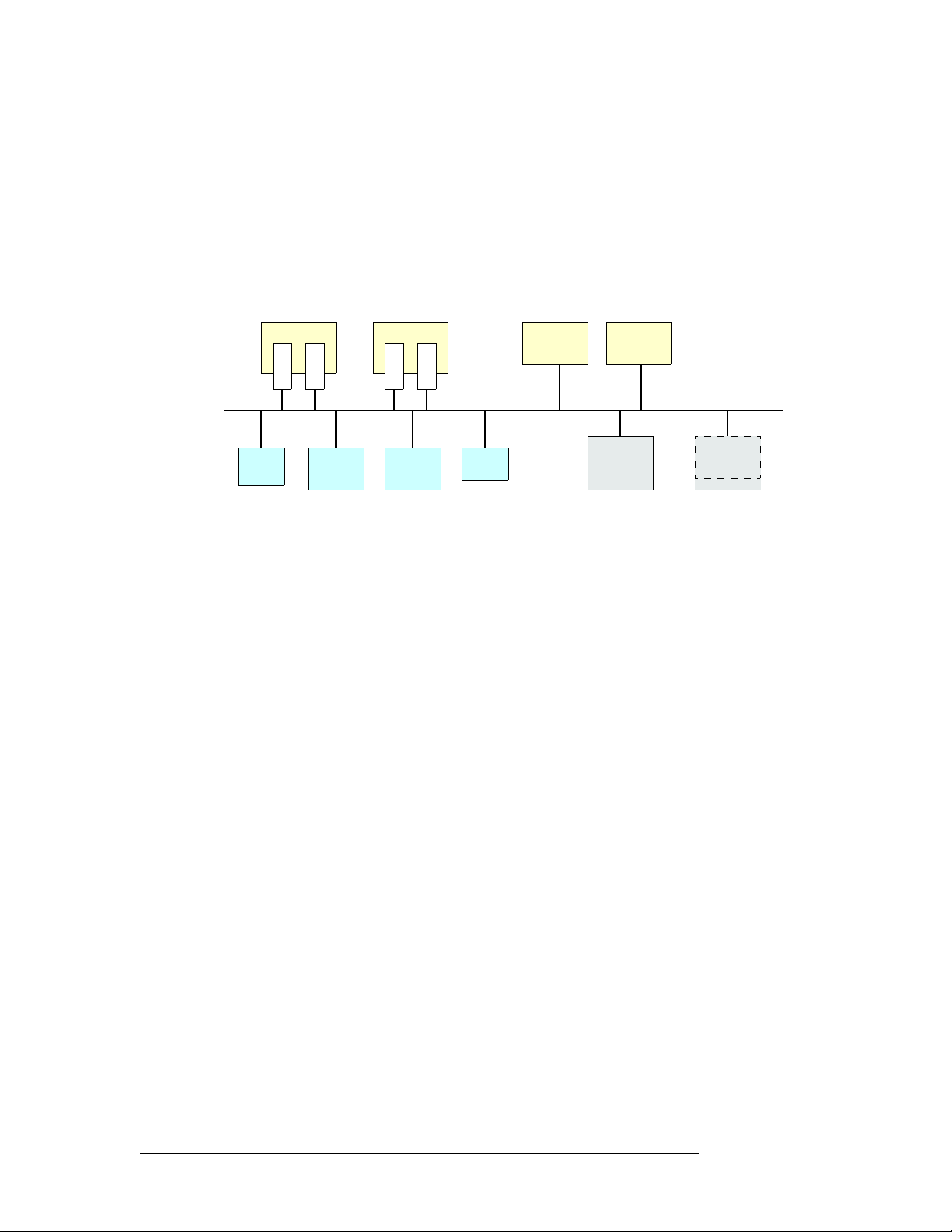
Figure 2-1 shows the basic relationships in a master control system:
NV5100MC NV5100MC
M
M
C
C
P
E
M
Config
PC
Figure 2-1. Master Control Network
Control
Panel
M
C
E
Control
Panel
M
•••
C
E
GUI
LAN
Imagestore
750
•••
Imagestore
750
NV9000
System
Controller
•••
Other
Devices
Master control can work in conjunction with an NV9000 router control system. In such a configuration, a channel has access to the entire router input space, with the ability to select any router
source.
Most control panels can control one or more channels at any time
— but usually one at a time.
Operators can select which channel(s) to control. When you change channels, control panel updates
take about a second. We say that the panel attaches the newly selected channel, and the channel’s
own source layout, transition rates, and layer presets are available for use.
Each channel can also be operated under automation. A channel can be controlled by multiple control panels.
The panel’s features when it is controlling an Imagestore 750 are quite different from the same
panel’s features when it is controlling an MCE or MCPM. (This guide discusses only the features
that support Imagestore 750s.)
NV9000 Router Control System
A master control system can be viewed as a part of an NV9000 system. Alternatively, the NV9000
can be regarded as a provider of inputs to the master control system.
In either case, master control allows router outputs as master control inputs and allows an operator
(or automation) to take router sources to the master control output.
The NV9000 system is a requirement for master control systems that use Imagestore 750s.
An NV5100MC frame used in conjunction with an NV9000 system must be connected to the
NV9000 (in the control section of the master control frame).
6 Rev 1.0 • 29 Nov 11
Page 19

2. Introduction
Imagestore 750 Overview
Control Panels
Presently there are 2 hardware control panels and 1 software control panel (GUI) that support
Imagestore 750s:
iMC-Panel-GUI A software control panel, also called the “GUI.” This panel also runs on a PC
and has a graphical user interface. This GUI is a software emulation of the
iMC-Panel-200. This GUI is designed to operate with (or without) a touchsensitive screen.
iMC-Panel-100 A 3RU rack-mounted panel with a separate rack-mountable display. This
panel has reduced size (just over 3″ in depth) and reduced cost.
iMC-Panel-200 A compact hardware control panel that has a large LCD touchscreen, many
function buttons, and a joystick. The iMC-Panel-200 mounts on a desktop or
work surface. All buttons have LCD legends and color-coding.
iMC-Panel-300 A “full-size” control panel that has a large LCD touchscreen, many function
buttons, and a joystick. The iMC-Panel-300 mounts on a desktop or work
surface. All but 2 buttons have LCD legends and color-coding.
Other Miranda Products
Listed here are products that relate to master control.
Tally Processor
Miranda offers a third-party “tally processor”— a 1RU device that provides 32 optically isolated
inputs and 32 relay outputs, also optically isolated. The tally processor can sense master control
events such as main source selections and transitions, trigger master control events, and control
various devices in your system. A master control network can include multiple tally processors.
Intuition XG
As a master control subsystem, Intuition XG is a combination of the following:
• Intuition XG
media clips and transmits the clips (fill and key) when directed by an Imagestore 750, MCE, or
MCPM.
• XMedia software for configuration and for composing, rendering, and previewing graphics.
Panel operators will generally not need to understand or use this software.
— a single- or dual-channel HD/SD graphics processor. This processor stores XG
Imagestore 750 Overview
The Imagestore 750 is an independent transition processor (also called a “channel branding processor”) that can operate as a stand-alone unit with or without automation, or as part of Miranda’s iMC
master control system. In the context of the combined master control system, it operates in conjunction with an NV9000 router control system, that provides video and audio sources, and one or more
master control panels, such as the iMC-Panel-100, that provide commands. The Imagestore 750
issues switching instructions to the NV9000 when it receives commands from a master control
panel.
Master Control • iMC-Panel-100 Operator’s Guide 7
Page 20
2. Introduction
Imagestore 750 Overview
The Imagestore 750 is essentially an A/B transition processor that inserts video effects (DVEs and
DSKs) and voice-overs into its output. It has many configuration options.
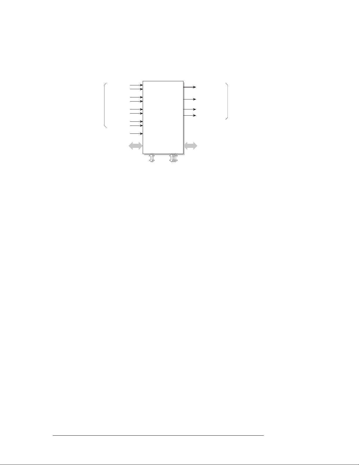
This is a system block diagram of the Imagestore 750:
Video In
D (or Key 3)
GPIO, LTC, Metadata
C (or Fill 3)
Fill 1
Key 1
Fill 2
Key 2
Ref
A
B
Imagestore
750
LAN 1, 2 COM 14
Program Out
Preview Out
Clean Out
Monitor Out
AES In, Out
Video Out
Inputs and outputs of the Imagestore 750 include:
• Four SDI inputs, A–D. These accept HD or SD input.
• Two external keyer pairs (fill and key). Inputs C and D can be used for a third keyer pair.
• A GPIO connector that supports 16 GPIO ports (each configurable as an input or an output),
LTC, and Dolby metadata.
• 16 AES inputs and 16 AES outputs.
• Four SDI outputs (program, preview, clean-feed, and monitor).
There are also 4 COM ports and 2 Ethernet ports.
8 Rev 1.0 • 29 Nov 11
Page 21
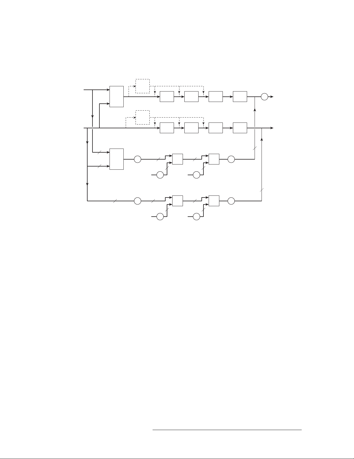
Conceptual Model
This diagram shows the Imagestore 750’s native conceptual model:
(option)
Video
A
B
Video
A/B
Mixer
DVE 1
DVE2
DSK 1 DSK 2 DSK 3 DSK 4
(option)
DVE 1
DVE2
DSK 1 DSK 2 DSK 3 DSK 4
2. Introduction
Imagestore 750 Overview
Program
Output
FTB
Preview
Output
16
Program
Audio
Preview
Audio
16
Audio
Audio
A
16
A/B
Mixer
B
16
16
Gain,
Shuffle
Gain,
Shuffle
Audio
Clip
Audio
Clip
16
16 16
Gain,
Shuffle
16
16 16
Gain,
Shuffle
Audio
Clip
Audio
Clip
16
Gain,
Shuffle
16
Gain,
Shuffle
VO 1 VO 2
VO 1 VO 2
Gain,
FTS
Gain,
FTS
There are two video processing paths, program and preview. Each includes 4 downstream keyers
(DSKs) and an optional DVE processor.
After audio is disembedded, the audio processing path includes an A/B mixer for 16 audio channels
and two voice-over processors, also for the 16 channels. Audio is re-embedded in program and preview audio after processing.
The model also includes a clean-feed (video) output and a (video) monitor output. There are many
selectable tap locations for these outputs.
Master Control • iMC-Panel-100 Operator’s Guide 9
Page 22
2. Introduction
Imagestore 750 Overview
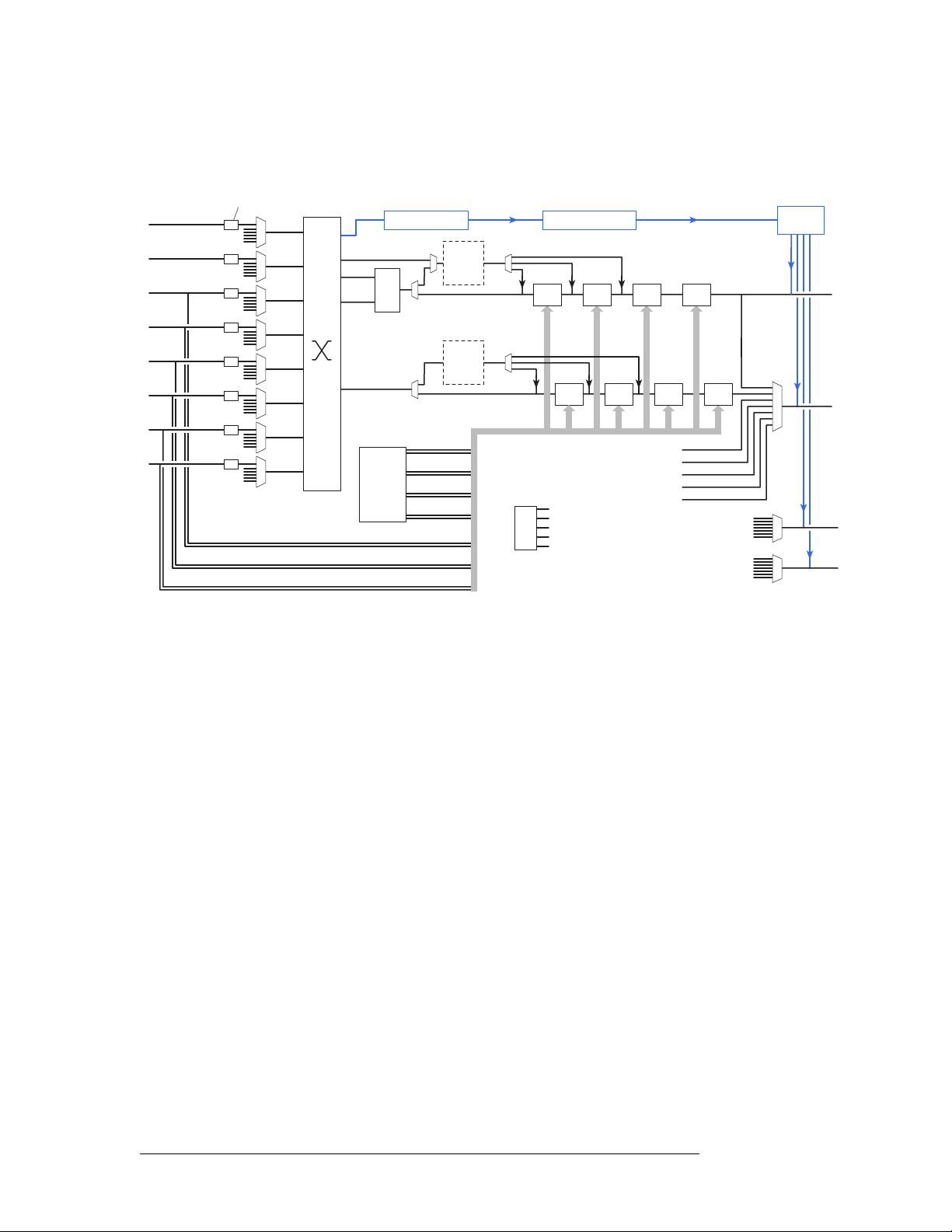
Detailed Model
This diagram shows a more detailed view of the Imagestore 750’s video processing:
Rectangular mask (8x)
SDI
SDI
SDI
SDI
SDI
SDI
SDI
SDI
test signals
test signals
test signals
test signals
test signals
test signals
test signals
test signals
Fill2
Key2
Fill1
Key1
A
B
C
D
Disembed Audio
A
A/B
Mix
B
Internal
Store
DVE1
(DVE2)
DVE1
(DVE2)
Fill1, Key1
Fill2, Key2
Fill3, Key3
Fill4, Key4
Ext. Fill3, Key3
Ext. Fill2, Key2
Ext. Fill1, Key1
Audio Processing
DSK1 DSK2 DSK3 DSK4
Test signals
Color Field 1
Color Field 2
Color Field 3
Test Pattern 1
Test Pattern 2
DSK1
DSK2 DSK3 DSK4
PGM A/B Mix
PGM DVE
PGM DSK1
PGM DSK2
PGM DSK3
Embed
Audio
PGM Out
PVW Out
CLN Out
MON Out
Each input (A, B, C, D, Fill1, Key1, Fill2, and Key2) can be individually selected as an SDI input
or one of 5 test signals. (Each SDI input can be subject to a rectangular clipping mask.)
Inputs C and D can be used as a (fill3, key3) pair. The Imagestore 750 can use any of its fill/key
inputs to receive clips from an Intuition XG processor. The Intuition XG processor produces up to 8
“XG keyer layers.” The Imagestore 750 sends commands to the Intuition XG processor that control
the playout of the clips.
Both the A and B side of the A/B mixers can connect to any of the inputs (A, B, C, D, Fill1, Key1,
Fill2, and Key2). Similarly, any of the DVEs can connect to any of those inputs.
The DVEs can also accept the output of the A/B mixer. The DVE output (either DVE1 or DVE2)
can be inserted in the processing path in one of 3 places: before DSK1, before DSK2, or before
DSK3. The DVE processing section is a purchase option. The DVE processor can be bypassed if it
is installed.
The Imagestore 750 has storage supporting internal keyers (logos, etc.). Inputs C and D can be used
as external keyer (fill3, key3).
The preview output can present video from one of several different tap points. Similarly, the cleanfeed (CLN) output and the monitor (MON) outputs can present video from several different tap
points.
Audio is disembedded from SDI sources, sent to the audio processing section, and re-embedded on
output. The audio is re-embedded in the PGM, PVW, CLN, and MON outputs.
10 Rev 1.0 • 29 Nov 11
Page 23

Control Panel Features
The iMC-Panel-100 offers the following features. (In many cases, the features are those of the
Imagestore 750 under control.)
• Configurable function buttons.
All master control panels have a set of buttons whose functions can vary according to the needs
of the facility and the operator. When it is controlling an Imagestore 750, the iMC-Panel-100
has 5 sets of customer-definable buttons.
• Channel selection, including ‘no channel’ mode, and ganged channels.
Your panel will usually have a default channel which is the channel selected when the panel
powers up. Your panel might be configured so that its default channel is part of a channel gang.
That is called “automatic gang mode.” Whenever that channel is selected, all the channels in the
gang are selected.
The 8 buttons in the top row of the iMC-Panel-100’s display are meant to be channel selection
buttons, but are configurable for any function. As channel selection buttons, they can display
thumbnail images for the channels. (The thumbnails are static and do not change with the content of the channel.)
• Salvos.
The iMC-Panel-100 can trigger a NV9000 control system salvo each time a channel change
occurs. For example, a salvo can be programmed to change your entire audio/video monitor
configuration instantly. Refer to the NV9000-SE Utilities User’s Guide for instructions on programming system salvos.
Salvos can also be assigned to panel buttons.
S Salvos are inhibited when a channel gang is in effect.
• Independent downstream keyers (DSKs). When it is controlling an Imagestore 750, the iMCPanel-100 can control 4 independent (linear) DSKs, each with separate key and fill inputs.
Keyer parameters (e.g., clip, gain, and transparency) are configured independently in each
Imagestore 750.
The DSKs handle internal keys (stills and animations) as well as (up to 3) external keys.
• DVEs.
A DVE (digital video effect) is a sequence of operations that can dynamically scale and position a video image on the screen, overlaying the main source. A DVE might perform other
effects too. DVEs are created in the DVE Editor. DVEs are stored within the Imagestore 750.
The panel supports up to 4 independent DVEs. Not all Imagestore 750s have DVE processors.
If your panel is controlling such an Imagestore 750, its DVE buttons, if any, are disabled.
• XG layers.
An XG layer (or clip) is one of up to 8 outputs of an Intuition XG processor. When it is controlling an Imagestore 750, the panel can control up to 8 XG layers. XG layers are processed by
one of the DSKs. Usually there is a default DSK assigned to XG layers.
• Fade to black. Master control provides a fade-to-black and a fade-to-silence function.
• General-purpose I/O (GPIO). Control panels have two optically isolated inputs that can sense
external events and two relay outputs that can trigger external events.
The Imagestore 750 has GPIs can be associated with Imagestore 750 macros.
2. Introduction
Control Panel Features
Master Control • iMC-Panel-100 Operator’s Guide 11
Page 24

2. Introduction
Control Panel Features
• Audio monitoring.
The iMC-Panel-100 has two audio monitor knobs, but they are not used when the panel is controlling an Imagestore 750s.
• Audio channel control.
The Imagestore 750 processes 16 audio channels.
The Imagestore 750 has 5 audio sections: program input audio, program output audio, preset
input audio, and voice-over 1 audio and voice-over 2 audio. The Imagestore 750 has gain control, inversion, and 16-channel shuffles for each of these 5 sections.
The iMC-Panel-100 has 3 knobs for program audio output, preset audio input, and voice-over
level. (These are live controls.)
• Panel lock. You can use a ‘Panel Lock’ button to prevent accidental changes to the panel settings.
• Automation control. You can enable or inhibit automation with a button press. There are 4 automation assist functions, such as ‘Cue Next’ and ‘Skip Next’.
• Source groups. The iMC-Panel-100 can have up to 16 source buttons. The Imagestore 750
allows the definition of multiple source groups. Each of those source groups can be mapped to
the source buttons of the iMC-Panel-100. The sources in a group are selected from the sources
defined in the NV9000 system. Thus, all NV9000 sources are potentially accessible.
12 Rev 1.0 • 29 Nov 11
Page 25

3. Control Panel
Chapter 3 describes the structure and functioning of the iMC-Panel-100as it applies to the Imagestore 750. It presents the following topics:
• Panel Summary
• Functional Sections of the Panel
• Definable Button Functions
• Connectors
Panel Summary
The iMC-Panel-100 is a configurable master control panel. It has two parts:
• 3RU rack-mountable button panel, 19.0″ wide × 5.22″ high × 3.7″ deep.
You can also mount the button panel in a recess of a console surface.
The rear of the panel includes 2 USB ports, one VGA port, 2 (redundant) power supply connectors (Molex 4-pin), an Ethernet port, GPI/alarm connector, and fan outlet.
• VGA display.
The VGA display is third-party equipment you must purchase separately. We recommend, and
support, the Planar series of touchscreen monitors. This guide describes the Planar PT1495R
19″ monitor.
Touchscreen monitors from other manufacturers will probably not work as part of the iMCPanel-100. However, most non-touchscreen VGA monitors will work as part of the iMC-Panel-
100. The monitor you use must have a screen resolution of at least 1280×1024 pixels. The iMCPanel-100 supports resolutions up to 1920×1200.
A mouse must be used with a non-touchscreen monitor.
The display provides a menu and a number of “soft” function buttons.
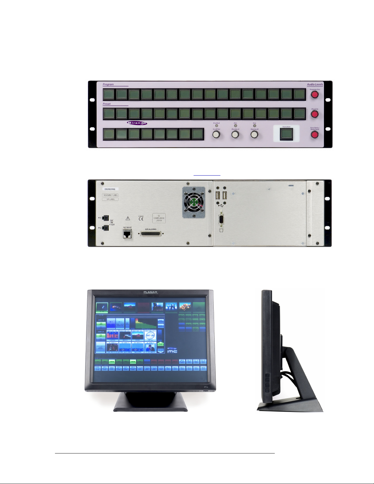
Button Panel
At the front of the iMC-Panel-100’s button panel are 41 color-coded LCD buttons and 6 knobs
(a.k.a. rotary encoders). Each LCD button has a 64×32 graphic display that usually shows 3 lines of
text, 8 characters per line. Sometimes a button can show graphics, as does the ‘Transition’ button at
the lower right.
Master Control • iMC-Panel-100 Operator’s Guide 13
Page 26
3. Control Panel
Panel Summary
Three knobs at the far right control audio levels. Two knobs at the bottom of the panel control audio
monitor levels. The remaining knob (labeled ‘Scroll/Set’, at the bottom) is for adjusting parameter
values.
Figure 3-1. iMC-Panel-100 Button Panel (Front View)
At the rear of the panel are two power connections, an Ethernet port, a fan, two USB ports, a VGA
connector, and a GPI/alarm connector. See GPI/Alarm
on page 37 for more information.
Figure 3-2. iMC-Panel-100 Button Panel (rear view)
Display Unit
Miranda supports the Planar series of touchscreens. This is the Planar PT1945R:
It has a removable stand and can be wall-mounted.
14 Rev 1.0 • 29 Nov 11
Page 27

3. Control Panel
Panel Summary
The iMC-Panel-100’s separate display unit provide a set of menus and “soft” function buttons in
which you can do the following:
• Select a channel (i.e., Imagestore 750, MCE, or MCPM).
• Select a main source or an over source.
• Choose a router source.
• Select a video effect and alter its settings.
• Manipulate audio.
• Change transition rates.
• Perform panel maintenance and updates.
• View status and error messages.
Some menus have a scrollbar with which to select items. You can use an on-screen “slider” to
adjust parameter values or you can enter a value using a touchscreen keypad. In many cases, you
can use the ‘Scroll/Set’ knob of the button panel to adjust parameter values.
The recommended display unit is a touchscreen: you press or touch buttons on the screen itself to
perform menu selections.
S Your panel will operate with a non-touchscreen display. In that case, you’ll use a mouse. (There
is no need for a keyboard).
Panel Buttons
Buttons appear in several colors and 3 brightness levels: off, low-tally, and high-tally.
Buttons allow you to choose sources and video effects and to make menu selections. Some buttons
display status. Pressing a button usually selects something. However, nothing happens when you
push a button that is disabled or off and nothing happens when you push a button that merely displays status.
The buttons on the panel display the following colors:
Low Green Low Blue Low Violet Low Orange Aqua High Red
High Green High Blue High Violet High Orange White High Amber
In addition to these 12 colors, a button can be dark (that is, off, or having no color). High red and
high amber usually indicate warnings.
The following color scheme usually applies. Exceptions will be noted.
• Non-selected state: low tally
• Selected state: high tally
Some buttons are toggles. Pressing a deselected toggle button will cause it to become selected.
Pressing a selected toggle button will make it deselected.
Some groups of buttons operate as a mutually exclusive set. Pressing a deselected button will cause
it to become selected and all other buttons in the set to become deselected. There are two types of
mutually exclusive buttons:
1 Pressing a selected button makes it deselected. (All other buttons in the set remain deselected.)
2 Pressing a selected button has no effect: the button remains selected.
— green, blue, violet, orange, or white.
— green, blue, violet, orange, or red, or aqua.
Master Control • iMC-Panel-100 Operator’s Guide 15
Page 28

3. Control Panel
Panel Summary
Soft buttons
The display has 3 rows of button:
• Top row.
• Aux/user buttons.
• Preview/user buttons.
Panel Knobs
Turning a knob clockwise increases the associated value until the maximum value is reached. After
that, turning the knob clockwise has no effect.
There are 8 large buttons in this row. All are configurable buttons. However, the row is
designed to support channel selection buttons that have thumbnail images representing the
channels.
The aux/user row has 16 buttons. The leftmost buttons are source buttons that you can use to
direct a source to an auxiliary device. The rightmost buttons (if any) are customer-configurable
buttons.
S The source buttons are identical in all 4 button rows: the aux and preview rows of the dis-
play and the program and preset rows of the button panel.
The preview/user row has 16 buttons. All 16 buttons are customer-configurable buttons. (The
button row is used to control the preview bus of an MCE when the panel is controlling an MCE.
Turning the knob counter-clockwise decreases the associated value until the minimum value is
reached. After that, turning the knob counter-clockwise has no effect.
The function assigned to a knob might be disabled. In that case, turning the knob does nothing.
S The LED above the ‘Scroll/Set’ knob illuminates when scrolling is enabled.
S The LEDS above the audio monitor buttons illuminate when the monitor is “dimmed.”
16 Rev 1.0 • 29 Nov 11
Page 29
Functional Sections of the Panel
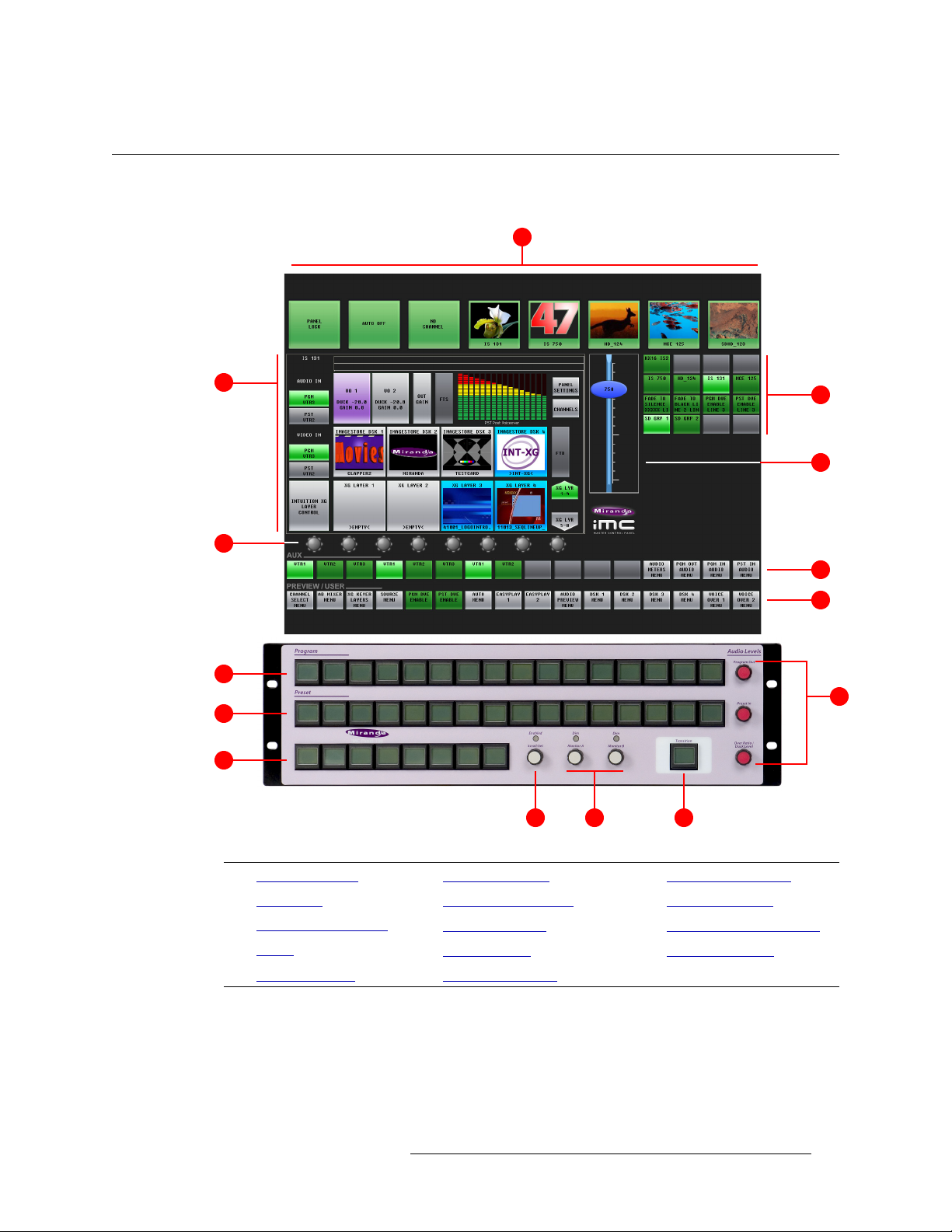
Figure 3-3 shows the location of the iMC-Panel-100’s touchscreen, function buttons, and controls.
Display
3. Control Panel
Functional Sections of the Panel
1
2
5
Button
Panel
8
9
11
Figure 3-3. Sections of the iMC-Panel-100
3
4
6
7
10
1412 13
1 Top row buttons 6 Aux/user buttons 11 Bottom row buttons
2 Menu area 7 Preview/user buttons 12 ‘Scroll/Set’ knob
Configurable buttons
3
4
Slider
8 Program buttons 13 Audio monitoring knobs
9 Preset buttons 14 Transition button
5 Knob “Proxies” 10 Audio level knobs
Master Control • iMC-Panel-100 Operator’s Guide 17
Page 30

3. Control Panel
Functional Sections of the Panel
Following are brief descriptions of each section:
1 Top row buttons
The 8 large buttons in this row are all customer-configurable buttons. However, the row is
designed to accommodate channel selection buttons that have thumbnail images representing
the channels.
2 Menu area
Using the menus of the display, you can adjust parameters and control system functions. Associated with the menu are 8 knob “proxies” for adjustment of parameters. See Menu Area
page 21 for detail.
3 Configurable buttons
The configurable button section includes 16 buttons, each of which may be programmed to perform functions such as channel selection, menu selection, or source group selection. Some of
these buttons can function as status indicators. See Configurable Button Section
detail.
Buttons in other sections of the panel are also configurable.
4 Slider
The slider helps you make certain parameter adjustments such as changes to the size or position
of DSKs. See On-Screen
5 Knob “Proxies”
The 8 knob “proxies” under the menu area allow you to adjust menu parameters. Not all of
these “knobs” are active all the time. When a knob is active, the menu shows a colored indicator
near the knob.
Touch (or click) a knob proxy to select it. When you do, the knob proxy turns green and a slider
appears, to the right of the menu, and the ‘Scroll/Set’ knob of the button panel becomes
enabled. You can use either the slider or the ‘Scroll/Set’ button to perform parameter adjustments.
6 Aux/user buttons
When the panel is controlling an Imagestore 750, this button row contains source buttons and
customer-definable buttons.
The sources are the same sources as on the preset and program button rows. These buttons
allow you to direct a main source to an auxiliary device such as a waveform monitor.
S Imagestore 750s have an “aux bus follow” option. Depending on how this option is set,
your aux buttons might follow the program or preset bus or might remain independent.
When they follow the program bus, whatever source becomes selected on the program bus
is also selected on the aux bus. When they follow the preset bus, whatever source becomes
selected on the preset bus is also selected on the aux bus.
In any case, you can always use the aux buttons, normally, regardless of what was selected
on the preset or program bus.
S If the Imagestore 750 is not configured for controlling an auxiliary device, the aux button
row’s source buttons are disabled (dark).
on
on page 22 for
“Knobs” and the Slider on page 24 for detail.
18 Rev 1.0 • 29 Nov 11
Page 31

3. Control Panel
Functional Sections of the Panel
7 Preview/user buttons
This row of buttons is a set of “preview” buttons when the panel is controlling an MCE or
MCPM and it is a set of customer-definable buttons when the panel is controlling an Imagestore
750. (Among the customer-definable buttons can be “menu” buttons.)
8 Program buttons
The 16 program buttons include main source buttons and “layer” buttons. The layer buttons can
be configured as video effects or voice-overs. The number of main sources, video effects, and
voice-overs varies according to the panel configuration.
Whatever main source, video effects, and voice-overs are selected on the program buttons form
the program output of the Imagestore 750 that is currently controlled by the iMC-Panel-100.
See P
reset and Program Buttons on page 25 for detail.
S The preset and program buses behave differently under different transition options. See
Transition Options
9 Preset buttons
The preset buttons allows you to set up the state of the program output that will exist after the
next transition.
The preset buttons include main source buttons and “layer” buttons. In fact, the preset bus and
program bus have the same button functions. The function assigned to a program button is also
assigned to the preset button directly beneath it.
Whatever main source, video effects, and voice-overs are selected on the preset bus form the
preview output of the Imagestore 750 that is currently controlled by the iMC-Panel-100.
See P
reset and Program Buttons on page 25 for detail.
on page 88.
S The preset and program buses behave differently under different transition options. See
Transition Options
on page 88.
10 Audio level knobs
The panel has 3 rotary knobs in this section, labeled:
•Program Out
This knob controls either the program output level as a whole or (when a voice-over is
active on the program bus) the voice-over level.
•Preset In
This knob controls the preset input level (as a whole).
• Over Ratio / Duck Level
When the panel is controlling an Imagestore 750, this knob controls the audio level of the
main source when a voice-over is mixed with program output. (That is called the “duck
level.” The term “over ratio” applies only to MCEs and MCPMs.)
See Audio Levels
on page 23 for detail.
11 Bottom row buttons
The buttons in this section are all configurable. (See Definable Button Functions
, on page 30.)
Master Control • iMC-Panel-100 Operator’s Guide 19
Page 32

3. Control Panel
Functional Sections of the Panel
12 ‘Scroll/Set’ knob
When you touch (or click) the knob proxy (under the menu) associated with some parameter
(such as voice-over level), the slider appears on the display and the ‘Scroll/Set’ knob of the button panel becomes enabled. You can use either the ‘Scroll/Set’ knob or the slider to adjust the
parameter.
13 Audio monitoring knobs
The panel has two rotary knobs in this section, labeled:
• Monitor A
• Monitor B
The knobs apply when the panel is controlling an MCE or an MCPM. The knobs do not apply
to Imagestore 750s.
14 Transition button
The transition button displays the transition type (as a graphic) and the transition rate (in text).
‘Cut’ transitions involve no rate and for cut transitions, the button displays no rate text.
The button is bright orange.
Pressing the transition button initiates a transition in the Imagestore 750 according to the iMCPanel-100 setup.
See Transition Button
on page 30 for detail.
Top Row Buttons
Figure 3-5 shows the top row of buttons:
Figure 3-4. Menu Area (Sample Showing Knob Proxies)
The 8 large buttons in this row are all configurable buttons. However, the row is designed to
accommodate channel selection buttons that have thumbnail images representing the channels.
20 Rev 1.0 • 29 Nov 11
Page 33

Menu Area
Figure 3-5 shows the menu area and its 8 associated “knobs”:
3. Control Panel
Functional Sections of the Panel
Figure 3-5. Menu Area (Sample Showing Knob Proxies)
The menu area presents a number of different menus that allow you to perform source selections
and adjust operating parameters.
Menu buttons allow you to select the menu that appears in the menu area. Menu buttons are toggles: pressing the button once displays the menu; pressing the button again displays the main menu.
Some menus allow you to adjust function parameters, such as the ‘DSK Rates, CGT, and Keying’
menu shown in Figure 3-5. You can adjust function parameters in two ways:
• Using the adjacent knob proxies.
Touch (or click) the knob proxy. Use the slider that appears or the ‘Scroll/Set’ knob that
becomes enabled to adjust the parameter.
• Pressing the keypad image within the menu itself.
Use the on-screen keypad that appears to adjust numeric values.
The menu area has a region at the top for status and error messages and another region at the top for
informative messages.
Refer to Chapter 4, Menus
, on page 31 for a comprehensive review of all menus.
Master Control • iMC-Panel-100 Operator’s Guide 21
Page 34

3. Control Panel
Functional Sections of the Panel
Configurable Button Section
Figure 3-6 shows the configurable button section:
Figure 3-6. Configurable Button Section
The configurable button section includes 16 buttons, each of which may be programmed to perform
various functions such as channel selection, GPI triggers, or machine control. The buttons can also
be status buttons.
Each button displays 3 rows of 8 characters. The button functions and button legends are determined during panel configuration. Each configured button is illuminated. Buttons that are not configured are dark and have no legend. The illumination can be high or low tally
amber, or red. Red usually indicates a problem.
— green, white,
There are about 70 different button functions available to the configurer. You, the operator, will
find a variety of these button types in the configurable button section of the panel you are using.
S Bottom Row Buttons of the panel are configurable too.
This table lists the button function classes for controlling Imagestore 750s:
Channel Selection Transition Type Salvo Automation Assist
System Control Transition Rate Menu
See Definable Button Functions
on page 30 for details regarding these button functions.
22 Rev 1.0 • 29 Nov 11
Page 35

Audio Levels
Figure 3-7 shows the audio level section in which there are 3 knobs:
Figure 3-7. Audio Level Section
S
The knobs are red because level changes affect on-air levels.
3. Control Panel
Functional Sections of the Panel
‘Program Out’ Knob
This knob controls either the program output level or voice-over level.
When no voice-over is active on the program bus, the knob controls the overall program output
level.
When one voice-over is active on the program bus, the knob controls the level of the selected
voice-over signal.
When both voice-overs are active on the program bus, the knob controls the level of both voiceover signals. The effect is additive: a turn of the knob adds the same amount to each voice-over
level.
This knob adjusts the audio level in increments of 0.5 dB, from –100.0 dB to +28.0 dB.
‘Preset In’ Knob
When the panel is controlling an Imagestore 750, this knob controls the preset input level.
This knob adjusts the audio level in increments of 0.5 dB, from –100.0 dB to +28.0 dB.
‘Over Ratio/Duck Level’ Knob
When the panel is controlling an Imagestore 750, this knob controls the audio level of the program
source when a voice-over is mixed with program output. (That is called the “duck level.” The term
“over ratio” applies only to MCEs and MCPMs.)
When no voice-over is active on the program bus, the knob is inoperative.
When one voice-over is active on the program bus, the knob controls the audio level of the program
source for the selected voice-over signal.
When both voice-overs are active on the program bus, the knob controls the level of the program
source for both voice-over signals. The effect is additive: a turn of the knob adds the same amount
to each voice-over level.
This knob adjusts the duck level in increments of 0.5 dB, from –100.0 dB to +28.0 dB.
Master Control • iMC-Panel-100 Operator’s Guide 23
Page 36

3. Control Panel
Functional Sections of the Panel
On-Screen “Knobs” and the Slider
There are 8 knob “proxies” under the menu area:
When you select a knob proxy, it turns green, a slider then appears to the right of the menu area, and
the ‘Scroll/Set’ button of the button panel becomes enabled. Use either the slider or the ‘Scroll/Set’
knob to adjust parameter values.
Figure 3-8 shows the slider and the ‘Scroll/Set’ knob:
Unselected Selected
Figure 3-8. Slider
The slider scale changes according to the value being adjusted. If you are adjusting an audio level,
the range is –100.0
dB to +28.0 dB. If you are adjusting transparency, the scale shows values in the
range 0 to 512.
The slider is for rapid and coarse adjustment only. Its steps are large and uneven. To operate the
slider, click or touch and drag the oval up or down. The setting value is displayed within the oval.
Audio Monitoring
Figure 3-9 shows the monitor section in which there are 2 knobs and 2 LEDs:
Figure 3-9. Audio Monitor Section
The audio monitor knobs are not used for panels controlling Imagestore 750s, but they are used for
panels controlling MCEs or MCPMs.
24 Rev 1.0 • 29 Nov 11
Page 37

3. Control Panel
Functional Sections of the Panel
Preset and Program Buttons
The preset and program buttons, on the button panel, are each divided into two parts:
1 Source buttons.
The leftmost buttons represent sources only.
Source buttons are usually green, high-tally when selected and low-tally when not. If a source
has a problem (e.g., LOS or non-sync), it is high-tally amber when unselected and red when
selected. Unused source buttons are dark.
Source buttons can be configured so that buttons for selected sources are white or red.
2 “Layer” buttons.
The rightmost buttons can be configured as video effects, and voice-overs:
The layer section provides up to 4 DSKs, 4 DVEs, 8 XG layers, and 2 voice-overs (voiceovers).
Sixteen main sources buttons and 18 “layer” buttons obviously do not fit in a button row. The
panel’s configurer will have made trade-offs in this regard.
Source buttons and layer buttons together forming 2 processing sequences:
Program Selections on the program buttons compose the program output of the currently
selected Imagestore 750.
Preset Selections on the preset buttons preview the content of the program bus as it will
appear after the next transition.
S The preset buttons can be configured to tally according to the “PresStation” model or the tradi-
tional model.
The preset bus (and its output) allow you to set up new output for the program bus. When the new
output is ready, you press the transition button and the Imagestore 750 transitions the contents of
the preset bus to the program bus.
S The preset and program buses behave differently under different transition options. For exam-
ple, the preset buttons can be configured to tally according to the “PresStation” model or the
traditional model. See Transition Options
Master Control • iMC-Panel-100 Operator’s Guide 25
on page 88.
Page 38

3. Control Panel
Functional Sections of the Panel
Your iMC-Panel-100 might be configured with one or more “group select” button. If it has group
select button(s), you can switch between several groups of sources. When you switch groups, the
source mnemonics of the selected group appear on the physical buttons.
In any case, up to 16 source buttons are available, using one group or another. Usually an iMCPanel-100 will have fewer than 16 source buttons.
Source buttons are mutually exclusive. Pressing one selects that source and deselects an other
source. Video effects and voice-overs are independent and not mutually exclusive.
Aux/User and Preview/User Buttons
The aux/user buttons and the preview/user buttons are on the display unit:
Aux/User
Preview/User
When the panel is controlling an Imagestore 750, all the buttons in the ‘Preview/User’ row are customer-definable. There are several dozen configurable button types among which are menu buttons.
The aux/user buttons, on the display unit, are divided into two parts:
1 Source buttons.
The leftmost buttons if the aux/user row represent sources only. They are the same sources as on
the preview, program, and preset buttons.
Source buttons are usually green, high-tally when selected and low-tally when not. If a main
source has a problem (e.g., LOS or non-sync), it is high-tally amber when unselected and red
when selected. Unused main sources are dark.
S If the Imagestore 750 under control does not support an auxiliary device, all source buttons
of the aux/user row are disabled (dark).
S Imagestore 750s have an “aux bus follow” option. Depending on how this option is set,
your aux buttons might follow the program or preset bus or might remain independent.
When they follow the program bus, whatever source becomes selected on the program bus
is also selected on the aux bus. When they follow the preset bus, whatever source becomes
selected on the preset bus is also selected on the aux bus.
In any case, it is always possible to use the aux buttons, normally, regardless of what was
selected on the preset or program bus.
2 “Customer-definable buttons.
The rightmost buttons of the aux/user row, if not committed to sources, are customer-definable
buttons. If your aux/user row has few source buttons and few customer-definable buttons, the
intervening buttons will be unused (and dark).
26 Rev 1.0 • 29 Nov 11
Page 39

3. Control Panel
Functional Sections of the Panel
Button Details
Source Button Characteristics
The source buttons display an 8-character source name on the button.
The main source buttons use the following color scheme:
Dark Button is not in use.
Low Green Not selected.
High Green Selected video.
High Amber An unselected video source is non-sync or LOS, or an unselected audio source
is LOS.
High Red The selected video source is non-sync or LOS, or audio source is LOS.
The touchscreen displays the source status. If status is “OK,” there is no message text. These are
possible fault conditions:
1 Video LOS 3 Video Non-Sync
2 Audio LOS 4 Audio Problem
The numbers here show the priority of the messages (in case more than one condition arises).
“Hot Cuts”
When you press a button on the program bus, whether main source, video effect, or voice-over, the
iMC-Panel-100 will request the Imagestore 750 to perform a “hot cut” on the program bus. The
Imagestore 750 performs the hot cut without benefit of a transition.
Video Effects
Selected video effects overlay the selected main video source. Video effects are cumulative and
apply in the order defined by the Imagestore 750.
DSKs are applied in this order: DSK1, DSK2, DSK3, DSK4.
If the Imagestore 750 has a DVE unit, it can insert DVEs in the video stream in one of three places:
before DSK1, before DSK2, or before DSK3.
If the Imagestore 750 is connected to an Intuition XG processor, one of its DSKs can process XG
keyer layers from the Intuition XG.
Any one effect is electronically downstream and visually on top of all the effects preceding it in the
order. Any one effect is electronically upstream and visually under of all the effects following it in
the order.
“Downstream” effects modify “upstream” effects and the main source. Upstream effects never
modify downstream effects. For example, a DVE might transform the main source and DSK1, but
not DSK2 or DSK3.
S Please note: the order of effect buttons and the number of effects assigned to the buttons do not
affect the order in which the Imagestore 750 applies the effects. (Also, the source is always
upstream of any effect.)
Master Control • iMC-Panel-100 Operator’s Guide 27
Page 40

3. Control Panel
Functional Sections of the Panel
The video effect buttons use the following color scheme:
Dark The video effect is not supported by the Imagestore 750.
Low-tally blue The video effect is not selected.
High-tally blue The video effect is selected.
High-tally amber An unselected video effect has a problem (e.g. non-sync or LOS). Amber
High-tally red The selected video effect has a problem (e.g. non-sync or LOS). Red is an
A video effect button has 3 lines of 8 characters.
The first line of text identifies the video effect itself.
The second line of text identifies the effect assigned to the effect processor.
The third line of text varies:
• For DSKs, VOs, and XG keyers on the preset bus, the third line displays “CUT” or “FADE”
depending on how the effect is armed. If the effect is not armed, the third line of the button displays nothing.
is a warning flag.
error flag or a severe warning.
• For DVEs on the preset bus, the third line displays “ARMED” if the effect was armed. If the
effect is not armed, the third line of the button displays nothing.
• On the program bus, the third line generally is blank, but for XG keyers, the third line might
contain a portion of the XG keyer name if the name is longer than 8 characters.
• On the preset bus, for unarmed XG keyers, the third line generally is blank, the third line might
contain a portion of the XG keyer name if the name is longer than 8 characters.
Downstream Keyers
The 4 keyer buttons are independent toggles. A downstream keyer (DSK) is active when its button
is selected (high-tally) and inactive when its button is low-tally. (A DSK cannot actually be used
when it is non-sync or LOS.)
An external key is usually a pair of video sources
— a key and a fill. The key forms a mask for the
fill. An internal key is a stored still frame or an animation. External keys can be provided by an
Intuition XG processor.
A key source overlays the upstream source (and upstream effects) with specified clip, gain, and
transparency parameters that control the key values.
Any DSK button can be associated with any key source, including Intuition XG clips.
DVE
The 4 DVE buttons are independent toggles. A DVE is active (selected) when its button is hightally and inactive when its button is low-tally.
A DVE button is pre-configured with a DVE stored in the Imagestore 750.
There are button functions available (‘PGM DVE Enable’ and ‘PST DVE Enable’) that enable or
disable DVEs on the program button row and the preset button row.
28 Rev 1.0 • 29 Nov 11
Page 41

3. Control Panel
Functional Sections of the Panel
Video Effect Source Status
The touchscreen displays an effect’s source status. Possible fault conditions include LOS and nonsynchronous video.
You can check panel status to view all error conditions. Use the ‘Manage Log’ sub-menu under the
‘Panel’ menu. See page 93.
Voice-Overs
Like video effect buttons, the 2 voice-over button pairs on the program and preset bus are not mutu-
ally exclusive. When an over is selected on the program button row, its audio contributes to program audio. When an over is selected on the preset button row, it becomes armed and will play at
the next transition.
S An over function mixes the selected audio source to air, but it does not trigger audio playback.
Voice-Over Button Characteristics
The voice-over buttons use the following color scheme:
Low violet The voice-over is not selected.
High violet The voice-over is selected.
Voice-Over Source Status
The touchscreen displays an over’s source status. These are the fault conditions:
1LOS
2Problem
If status is “OK,” there will be no message.
The third line of text displays “CUT” or “FADE” depending on how the over was armed. If the
effect is not armed, the third line of the button is blank.
Bottom Row Buttons
These buttons are all configurable:
The configurable button functions are described under Definable Button Functions
, on page 30.
Master Control • iMC-Panel-100 Operator’s Guide 29
Page 42

3. Control Panel
Definable Button Functions
Transition Button
Pressing the transition button initiates a transition in the Imagestore 750 controlled by your panel.
You can change the transition rate and type.
The transition button is orange under normal circumstances. The transition button is high-tally
while the Imagestore 750 is performing a transition. Otherwise it is low-tally.
The maximum transition period is 999 frames. The minimum is 1.
When you press this button, the panel sends a transition request to the Imagestore 750.
Please note the following points regarding transitions:
• You can start a new transition only after the current transition has completed.
• You can always interrupt a transition in progress with a cut on the program bus.
• Fade transitions (cut-fade, V-fade, U-fade, and fade-cut, and others) involve a fade to black during the transition.
Definable Button Functions
Buttons in the configurable button section, the transition control section, and the system control
section of the iMC-Panel-100 can be redefined. These are the button function classes:
Channel Selection Menu Transition Type Automation Assist
Salvo System Control Transition Rate
Following are descriptions of the functions that can be assigned to definable buttons during configuration (using the MCS Panel Configuration Editor).
Remember that the iMC-Panel-100’s button legends are at the discretion of the configurer. They
might not be exactly what you see listed in this guide.
None
This kind of button has no function. On the panel, the button’s legend is blank and the button is
dark. (The iMC-Panel-100 can never enable or disable this kind of button.)
Channel Selection
An Imagestore 750 is equivalent to a channel. A typical iMC-Panel-100 configuration provides a
set of channel selection buttons. (You can also select channels in the menus.)
A channel can be configured to invoke an NV9000 salvo when selected. Consult your administrator
to determine which channels execute salvos.
30 Rev 1.0 • 29 Nov 11
Page 43

3. Control Panel
Definable Button Functions
Your panel will usually have a default channel which is the channel that is selected when the panel
powers up. Your panel might be configured so that its default channel is part of a channel gang. If
so, you panel is configured in what is called “automatic gang mode.” Whenever the default channel
is selected, all the channels in the automatic channel gang are selected
There are 2 button types for channels:
• ‘Channel’ selection.
• ‘No Channels’.
Channel Select
A channel is equivalent to an Imagestore 750, an MCE, or an MCPM. Press a ‘Channel Select’ button to select a channel to control.
When you press a ‘Channel Select’ button, all status and configuration data for the newly selected
channel are downloaded to the panel. (It takes about one second.)
‘Channel Select’ buttons are mutually exclusive.
If “automatic gang mode” is in effect and the channel you select is the default channel, the ‘Channel Select’ button causes all channels in the automatic channel gang to be selected. If you have a
‘Channel Gang’ button, it becomes high-tally. The main channel in the gang (which is the default
channel, to which the button corresponds) tallies green and the follower channels in the gang tally
amber.
When “automatic gang mode” is not in effect or you are selecting a channel other than the default
channel, pressing the ‘Channel Select’ button does nothing more than acquire that channel. The
channel button tallies green unless there are problems.
‘Channel Select’ buttons use the following colors:
• Low-tally green. The associated channel is not selected.
• High-tally green. The associated channel is selected and communicating. The channel might or
might not be the main channel in a channel gang.
• High-tally amber. The associated channel is selected as a follower in a channel gang and is
communicating.
• High-tally red. The associated channel is selected, but the iMC-Panel-100 cannot establish
communication with it.
A channel selection button also displays a mnemonic for the associated Imagestore 750, MCE, or
MCPM.
— as a channel gang.
An Imagestore 750 can accept up to 4 concurrent connections: any combination of up to 4 control
panels may acquire the same channel at the same time. If a fifth control panel attempts to connect to
an Imagestore 750 that already has four control panel connected to it, the fifth control panel’s
request for connection will be ignored.
S Note to configurers: only one channel selection button may be assigned to a channel.
No Channels
A ‘No Channel’ button quickly disconnects the panel from all channels. (To restore operation,
select any channel.) These are the ‘No Channel’ button colors:
• Green. The panel is connected to a channel.
• Red. The panel is not connected to any channel.
Master Control • iMC-Panel-100 Operator’s Guide 31
Page 44

3. Control Panel
Definable Button Functions
S Note to configurers: a panel configuration can have only one ‘No Channel’ button.
S A “no channel” button is typically used in diagnostic situations.
Salvo
A panel might have one or more salvo buttons. Pressing a salvo button causes an NV9000 salvo to
execute. (This button requires a connected NV9000 router control system.)
S A channel change can also execute a salvo (except when you are switching to the default chan-
nel under automatic gang mode). That is because of the following restriction:
S When channel gang selection is enabled, salvos are inhibited.
System Control
There are 11 system control button types that can be present on your iMC-Panel-100:
Panel Lock Auto Off Fade-to-Black Macro Arm PGM DVE Enable
Group Select Audio Lock Fade-to-Silence Fire Macro PST DVE Enable
Kaleido-X Layout
Panel Lock
The panel lock button prevents you (or someone else) from accidentally making changes to the
Imagestore 750 while allowing you see the status of the Imagestore 750.
A panel lock button is a toggle. Press it once to lock the panel. Press it again to unlock the panel.
When the panel is locked:
• The panel lock button is high-tally red.
• All other buttons on the panel are disabled (locked) but their colors and legends remain
unchanged.
When the panel is locked and you press the panel lock button, the panel will become unlocked and
the panel will function normally.
Automation Off
The ‘Automation Off’ button is a toggle that enables or disables control of the currently selected
Imagestore 750 by an automation system. When this button is high-tally red, the currently selected
Imagestore 750 ignores commands from the automation system (if there is one). When this button
is low-tally green, the Imagestore 750 communicates with the automation system normally.
If the currently selected Imagestore 750 does not allow you to turn automation off and on, the button is disabled (dark).
Fade to Black
A ‘Fade To Black’ (FTB) button is a toggle. Press it once to fade the program output of the currently selected Imagestore 750 to both black and silence. Press it again to fade the program output
up from black and silence.
When the program output is in black/silence, fading to it, or fading up from it, the FTB and FTS
buttons of the main menu are red.
Fades occur at the FTB (and FTS) rate defined in the Imagestore 750 configuration. The FTB rate
is fixed in the Imagestore 750 configuration.
32 Rev 1.0 • 29 Nov 11
Page 45

3. Control Panel
Definable Button Functions
These are the button colors:
• High-tally green. The program output is fading or has faded to black.
• Low-tally green. The program output is fading or has faded back to normal.
Fade to Silence
A ‘Fade To Silence’ (FTS) button is a toggle. Press it once to fade the program output of the currently selected Imagestore 750 to silence. Press it again to fade the program output up from silence.
When the program output is silent, fading to it, or fading up from it, the FTS button of the main
menu is red.
Fades occur at the FTS rate defined in the Imagestore 750 configuration. The FTS rate is fixed in
the Imagestore 750 configuration.
These are the button colors:
• High-tally green. The program output is fading or has faded.
• Low-tally green. The program output is normal.
Group Select
The Imagestore 750 allows different source groups to be defined, where the sources in a group can
be mapped to the main source buttons of the panel.
A ‘Group Select’ button selects a source group. When the group is selected, its source mnemonics
appear on the main source buttons and (if your system is so configured) the sources in the group
appear on monitors in a monitor wall.
When you hold the button down, an automated transition is suspended. When you release the button, the transition continues. This is special-purpose button that lets you synchronize a transition
with a video feed that might be delayed unpredictably.
The button is low-tally green normally and high-tally amber when you press it.
Audio Lock
An ‘Audio Lock’ button is a toggle that enables or disables the 3 audio level knobs on the iMCPanel-100. (This feature helps prevent accidental changes to the audio levels)
The button is amber when the audio level knobs are locked.
Macro Arm
A ‘Macro Arm’ button selects an Imagestore 750 macro that will execute at the next transition.
S Certain macros can contain functions that must not execute during a transition. Such macros
will execute immediately after the transition completes.
Fire Macro
A ‘Fire Macro’ button executes an Imagestore 750 macro immediately.
PGM DVE Enable
A ‘PGM DVE Enable’ button enables or disables the use of DVE buttons on the program button
row.
Master Control • iMC-Panel-100 Operator’s Guide 33
Page 46

3. Control Panel
Definable Button Functions
PST DVE Enable
A ‘PST DVE Enable’ button enables or disables the use of DVE buttons on the preset button row.
KaleidoX Layout
A ‘Kaleido-X Layout’ button triggers a re-layout of a Kaleido-X multi-viewer. (The panel will
probably not have any ‘Kaleido-X Layout’ buttons if your master control system is not associated
with a Kaleido-X multi-viewer. The Kaleido-X multi-viewer supports multiple layouts.)
Menu
A menu button is a toggle. Press it once to place the indicated menu on the touchscreen. Press the
button again to return the main menu on the touchscreen.
There are 20 different menus that you can control:
• Main menu • DSK 1–4
• Automation • Channel Select
• Macro • PGM Out Audio
• XG Keyer Layers • PGM In Audio
• Audio Preview • PST In Audio
• Audio Meters • Voice-Over 1, 2
• Source • EasyPlay 1, 2
• A/B Mixer
Each menu button controls one menu. To control all 18 menus, you need 18 menu buttons.
Details on the different menus can be found in Chapter 5, Menus
, on page 45.
Automation Assist
There are 4 ‘Automation Assist’ button functions:
1 Cue next.
2 Drop next.
3 Hold next.
4 Take next.
These buttons allow you to manipulate the automation playout to a limited extent.
Transition Type
There are 8 ‘Transition Type’ button functions:
Cut V-fade (or fade-fade) V-fade preset 1
Fade/cut Cross fade (or X-fade) V-fade preset 2
Cut/fade U-fade
Transition type buttons are mutually exclusive. Press one to select the transition type the Imagestore 750 will use subsequently to execute transitions. All other transition type buttons become
deselected.
34 Rev 1.0 • 29 Nov 11
Page 47

Transition type buttons appear green and show graphics instead of text:
Cut Cut-Fade V-Fade Fade-Cut
3. Control Panel
Definable Button Functions
X-Fade
U-Fade V-Fade Preset 1 V-Fade Preset 2
(A U-type transition is like a V-fade, but with a pre-configured dwell period. The exact length of
the dwell period is defined by the person configuring the Imagestore 750. The characteristics of the
V-fade preset 1 and preset 2 types are also defined by the person configuring the Imagestore 750.)
If one or more transition functions on your panel were assigned to the “soft” buttons of the display.,
they look like these — the same basic graphics with different shading:
Cut Cut-Fade V-Fade Fade-Cut
X- Fade U-Fa de
V-fade Preset 1 V-fade preset 2
Transition Rate
There are 4 ‘Transition Rate’ button types:
1Slow.
2Medium.
3Fast.
4 Automation Rate.
The actual rates (i.e., the duration, in frames, of the transitions) that correspond to slow, medium,
and fast are defined in the Imagestore 750 configuration.
The ‘Automation Rate’ button selects whatever rate is in effect in your automation system (if there
is one).
The transition rate buttons are mutually exclusive. Press one to select the transition rate the Imagestore 750 will use subsequently to execute transitions. Other rate buttons become deselected.
Transition rate buttons are green.
S Keep in mind that each DSK has its own slow, fast, and medium rate settings. If you press the
‘Medium’ button, for instance, all DSKs will play out at their medium rate (unless they are set
to cut to the program output).
Master Control • iMC-Panel-100 Operator’s Guide 35
Page 48

3. Control Panel
Connectors
Notes
Remember that most of the iMC-Panel-100’s button legends are at the discretion of the configurer.
They might not be exactly what you see listed in this guide.
Connectors
At the rear of the iMC-Panel-100’s button panel are 2 power connectors, an Ethernet connector, two
USB connectors, a VGA connector (for the display unit) and a GPI/alarm connector:
USB Ports (2)
(to monitor)
VGA Port
(to monitor)
Power Supply
Connectors (2)
Ethernet
(RJ-45)
GPI/Alarms
(DB25)
Button Panel
Power
There are 2 power connectors, PS1 and PS2, for the sake of redundancy. Only one is required, but
with both, the iMC-Panel-100 will continue uninterrupted operation if one fails.
The PS0001 power supply that comes with the iMC-Panel-100 has a 4-pin plug that goes in the
connector. The plugs are keyed so that you cannot insert the plugs the wrong way:
1
3
n.c.
4
n.c.
Receptacle
Connect the line cable to the power supply and then to AC power. Then insert the 4-pin plug into
the iMC-Panel-100’s power connector.
The button panel has two power connectors. You can connect an additional PS0001 for redundancy.
2
12VDC
GND
12 VDC
3
n.c.
21GND
Plug
4
n.c.
36 Rev 1.0 • 29 Nov 11
Page 49

3. Control Panel
Connectors
Ethernet
The iMC-Panel-100 has one RJ-45 Ethernet connector. Connect the iMC-Panel-100 to the switch
on the master control network using CAT5 cable or better.
It is on this network that the iMC-Panel-100 communicates with MCPMs and with the configuration software. You (or your system administrator) must provide a unique IP address for the iMCPanel-100.
Without the IP address, the iMC-Panel-100 cannot communicate with MCPMs, MCEs, or the configuration software. Use the Panel ID menu under the Panel Menu to set the IP address and IP subnet mask.
The default IP address is 192.168.7.100. and the subnet mask must always be 255.255.255.0.
S Operators generally need not be concerned with the iMC-Panel-100’s network address.
USB Ports
There are two USB ports. If your iMC-Panel-100 uses a Planar touchscreen, one of the USB ports
will connect to the USB port of the touchscreen. If your panel does not have a touchscreen, one of
the USB ports will be used for a mouse (with which you manipulate items on the display). The
other port is discretionary.
VGA Port
The VGA port (HD15) connects to the VGA port of the display.
GPI/Alarm
The iMC-Panel-100 has a DB25 connector that supports GPI inputs, GPI outputs, and alarms:
GPI In 1
8
GND
20
7
13
25
unused
+
22
9
21
11
COM
Minor Alarm
23
NO
10
NC
Major Alarm
COM
NO
NC
25
12
24
If you intend to use any of these connections, make the connections according to figures 3-10 and
two diagrams.
GPI Input n
+
Customers
Circuit
Figure 3-10. GPI Input
Optical
Isolation
GPI Out 1
5
17
4
GPI In 2
19
GND
6
18
+
COM
NO
NC
1
14
+3.3V
C
E
unused
GPI Out 2
16
COM
3
NO
15
NC
10K
2
14
1
to internal bus
If your GPI input cable has a ground wire or
shielding, you can connect the ground (or
shielding) to the associated ground pin on the
DB25 connector. It is not necessary to do so.
The ground pin is not shown here.
Master Control • iMC-Panel-100 Operator’s Guide 37
Page 50

3. Control Panel
Connectors
from internal bus
Figure 3-11. GPI Output andAlarms
Power applied to the inputs can be from 5 to 24 VDC, and less than 30mA. Typically, 5 V at 1 mA.
Loads for the outputs can be larger:
+5V
alarm signal
+5V
GPI Output n
Alarm Relay
NC
COM
NO
NC
COM
NO
Customers
Circuit
Customers
Circuit
The GPI relay and alarm relay
circuits are identical.
Note: it is the NO circuit that closes
when the GPI output or alarm is
turned on. You can use the NC
circuit as well.
Max current: 1 A
Max voltage: 125 VAC, 110 VDC.
Max capacity: 62.5 VA, 33W.
Rated loads: 1 A at 30 VDC; 0.3 A at 110 VDC; 0.5A at 125 VAC.
Touchscreen Display
This describes the Planar PT1945R touchscreen display. If you have purchased another display
type, the connections will differ.)
At the bottom of the Planar touchscreen display (in a recess) are an AC power connector, a VGA
connector, an RS232 connector, a 3 mm audio jack, and a USB connector:
USB RS232 VGAAUDIO
USB Port
RS-232 Port
Audio Jack
Use the cables supplied with the display to make connections. See Chapter 4, Connectors
nection details.
Important: do not make any connection to the RS-232 port.
Notes:
1 You can obtain a manual for the Planar PT1945R monitor from the manufacturer at either
www.planartouch.com or www.planar.com.
2 The on/off switch is at the bottom of the display at the right, as you are viewing the display
from the front.
3 At the right of the display are 4 buttons (not shown here) that are to be used to set the operating
characteristics of the display.
AC InputVGA Port
, for con-
On/Off
Switch
38 Rev 1.0 • 29 Nov 11
Page 51

4. Installation
Chapter 4 addresses concepts relating to the installation of the iMC-Panel-100. It presents the following topics:
• Summary
• Button Panel
• Display
• Connections
Summary
The iMC-Panel-100 has two separate parts: a button panel and a display. There are several installation options.
You can rack-mount the button panel, either in a full rack or in a small desktop rack. It is also possible to mount the button panel in a recess in a console or desktop. The button panel is light in
weight and not very deep (3.7″). It does not require special rack supports and should allow adequate
knee clearance when mounted in a recess of a desktop.
The display comes with a detachable stand. It can be placed on a desktop or a shelf. In particular, it
can be placed on a shelf in a vertical rack, presumably above the button panel.
The display has VESA-standard 100 mm mounting holes that mate to a number of readily available
wall-mounting fixtures. The mounting fixture must be able to support 11 lb (5
S Exercise care not to damage the LCD surface of the display. When making wiring connections
to the display, place the display face-down on a flat, even surface that is clear of small parts or
debris.
kg).
Master Control • iMC-Panel-100 Operator’s Guide 39
Page 52

4. Installation
Button Panel
Button Panel
Rack-mounting the button panel is trivial. It need not be discussed.
If you wish to place the button panel in a recess of a console or desktop, you will need to cut a hole
in the console surface that will fit the button panel. This is a suggested cutout:
Drill for 3/16
screws, 4 places
2.25
[57.2]
1.495
[38.0]
Cut Through
5.10
[129.5]
5.24
[13 3.1]
0.355 [9.0]
19.02 [483.1]
17.73 [450.3]
The dimensions given above allow 0.01″ (0.25
the button panel, about 0.125″ (3
tilation. and about 0.06″ (1.5
mm) clearance on each short side of the panel’s enclosure for ven-
mm) clearance on the long sides of the enclosure.
mm) clearance on each edge of the front surface of
0.13R, 4 places
0.075
With recessed mounting, keep in mind that cables must run from the button panel to the display unit
and also to the Ethernet switch for the master control network and to external power supplies
(PS0001).
40 Rev 1.0 • 29 Nov 11
Page 53

Display
4. Installation
Display
(This applies to the Planar PT1945R touchscreen display. Other displays might differ.)
Mounting the display
Skip this section if you plan to use the display with its stand, on a flat surface.
1 If the stand is attached to the display, remove it. (There are 4 mounting screws. See the follow-
ing figures.)
2 Using finger pressure, slide the cover of the wiring recess down to remove it:
Remove 4 screws
Remove the cover of the
wiring recess
The wiring recess and the 4 mounting holes are now exposed.
3.94
[100.0]
3.94
[100.0]
Recess for Connectors
Attach the monitor to your mounting fixture. The mounting holes are tapped for M4 screws and
are 11mm deep. Use screws of a length appropriate for your mounting fixture.
The monitor has cooling vents at the rear. You should not block the vents.
Master Control • iMC-Panel-100 Operator’s Guide 41
Page 54

4. Installation
Connections
Connections
These are the connectors at the rear of the button panel:
DC Power (2)
Ethernet Ethernet
USB (2)
VGA
These are the connectors in the wiring recess of the display unit:
USB RS232 VGAAUDIO
USB Port
RS-232 Port
Audio Jack
AC InputVGA Port
GPI / Alarms
The GPI / Alarms connector of the button panel supports optional or discretionary wiring. The connector is a DB25. See Specifications
on page 145 for pinout and usage information.
On/Off
Switch
42 Rev 1.0 • 29 Nov 11
Page 55

4. Installation
Connections
Cabling
If you are using the display with its stand, route the cables through the cable harness (in the wiring
recess) and then through the cavity in the middle of the stand:
Cable Harness
Cables
Recess Cover
If you are not using the stand, it is not necessary to use the cable harness.
In any case, you will have to remove the cover of the wiring recess to perform some of these steps.
1 Connect a power supply or power supplies (PS0001) to either or both of the power connectors
of the button panel. Then connect the power supplies to AC power.
2 Connect the button panel’s Ethernet port to a port on the Ethernet switch of the master control
network.
Later, you will assign an IP address to the iMC-Panel-100.
3 Using the supplied VGA cable, connect the VGA port of the button panel to the VGA port of
the display:
4 Using the supplied USB cable, connect the USB port of the display to one of the USB ports of
the button panel:
5 If you wish to use a mouse with the iMC-Panel-100, connect the mouse to the remaining USB
port of the button panel. (The mouse must, of course, have a USB connector.)
Master Control • iMC-Panel-100 Operator’s Guide 43
Page 56

4. Installation
Connections
6 Using the supplied power cable, connect AC power to the display:
7 If you are using the display with a stand, ensure that the cables pass through the cable harness in
the wiring recess and then replace the recess cover. It snaps into place.
There is a small screw in the kit that comes with the display. Use it to secure the recess cover.
8 Turn on the display using its on/off switch located at the bottom, on the right as you are facing
the display from the front.
You should see the main menu of the iMC-Panel-100 on the display.
S Important: leave the RS232 port of the display unconnected.
Setup
1 Press the ‘Panel’ button of the main menu (of the display). Then press the ‘IP Setup’ button.
Use the buttons of the ‘IP Setup’ menu to enter an IP address, a subnet mask, and a gateway IP
address for the iMC-Panel-100. Generally the subnet mask should be 255.255.255.0. (All
devices on the master control network must have unique IP addresses.)
2 There are 4 buttons at the right side of the display:
Menu
Up
Down
Enter
On/Off
Press the menu button to reveal the on-screen adjustment menu. Press the button again to hide
the menu. (The menu will turn off by itself if it is idle for a certain amount of time. You can
change the timeout period.)
If you wish to adjust the display settings (e.g., brightness, language, menu timeout period), use
the up, down, and enter buttons to navigate through the entries of the menu.
Use the up and down buttons to increase or decrease parameter values.
Please refer to the Planar PT1945R manual for further details.
You can obtain a manual for the Planar PT1945R monitor from the manufacturer at either
nartouch.com
or www.planar.com.
www.pla-
44 Rev 1.0 • 29 Nov 11
Page 57

5. Menus
Chapter 5 describes the menus of the iMC-Panel-100 as they apply to Imagestore 750s. It presents
the following topics:
• About Menus
• Main Menu
• Automation Menu
• Channel Select Menu •DSK Menus
• Audio Preview Menu
• Program Input Audio Menu
• Preset Input Audio Menu
• A/B Mixer Menu
• XG Keyer Layers Menu
• “EasyPlay” Menus
About Menus
•Menu Button Conventions
•Audio Meters Menu
•Channel Select Menu
•Macro Menu
•Program Output Audio Menu
•Voice-Over Menus
•Sources Menu
•Panel Menu
The iMC-Panel-100’s color LCD touchscreen presents a number of selectable menus. Using the
menu(s), you can make source selections and parameter adjustments in several ways:
• Pressing the menu’s on-screen buttons or selecting an item in a list.
• Entering numeric values on the menu’s keypad by pressing the numeric menu buttons.
• Using any of the 8 knob proxies below the menu to set a parameter value. When selected, the
knob proxies enable an on-screen slider and the ‘Scroll/Set’ knob of the button panel, either of
which can be used to adjust the parameter.
Master Control • iMC-Panel-100 Operator’s Guide 45
Page 58

5. Menus
About Menus
Main Menu
Figure 5-2 illustrates the main menu components:
1 3 52 4
6
Figure 5-1. Menu Parts (Showing the Main Menu)
1 Menu name 3 Message bar 5 Navigation buttons
2 Error Bar 4 Toggle button 6 Knob proxies
Following are descriptions of each menu area:
1 Menu name
The current menu name is always present in the top left corner. This label changes dynamically
as you use different menus.
The main menu shows the channel name in this area.
2 Error Bar
The error bar is a rectangular area at the top of the menu that displays error messages (e.g.,
“Panel Not Connected”) and other important “alerts.”
3 Message bar
The message bar is a second rectangular area at the top of the menu that displays confirmation
messages when certain actions are in progress (e.g., “Changing Channels”) or have completed
(e.g., “NV9000 Salvo Successful”).
46 Rev 1.0 • 29 Nov 11
Page 59

5. Menus
About Menus
4 Selection buttons
A selection button lets you choose an one of several items. In Figure 5-2, the selection button
identified selects DSK 3.
5 Navigation buttons
A navigation button takes you to another menu. In Figure 5-2, the navigation button identified
selects the panel menu.
6 Knob proxies
You can adjust menu parameters (such as DSK transparency) by clicking a parameter’s associated knob “proxy” and moving the slider that appears or turning the ‘Scroll/Set’ knob. (The
proxy turns green when you select it.) For disabled parameters, the knob proxy is also disabled.
Enabled parameters show a green “asterisk” near by the proxy to show that it is usable.
Other Menus
Figure 5-2 illustrates the usual menu components:
1 3 52 4
6
7
8
Figure 5-2. Menu Parts
1 Menu name 3 Message bar 5 Functional area 7 Keypad Buttons
2 Error Bar 4 Toggle button 6 Navigation bar 8 Menu “knobs”
Master Control • iMC-Panel-100 Operator’s Guide 47
Page 60

5. Menus
About Menus
Following are descriptions of each menu area:
1 Menu name
The current menu name is always present in the top left corner. This label changes dynamically
as you change menus.
2 Error Bar
The error bar is a rectangular area at the top of the menu that displays error messages (e.g.,
“Panel Not Connected”) and other important “alerts.”
3 Message bar
The message bar is a second rectangular area at the top of the menu that displays confirmation
messages when certain actions are in progress (e.g., “Changing Channels”) or have completed
(e.g., “NV9000 Salvo Successful”).
4 Toggle button
A toggle button lets you switch a function or an option on and off or switch between two
options.
5 Functional area
The function area is the menu’s working area for all selections, adjustments, and modifications.
The content of the area changes according to the selected menu. Content can includes messages, lists of settings, a scroll bar, graphics, buttons, and a keypad.
6 Navigation bar
Some buttons are “navigation buttons.” These buttons either change the display, introducing
new controls, or take you to another menu altogether.
These are typical navigation buttons:
Press ‘Main Menu’ to return to the main menu.
Press ‘Back’ to jump one level up in the menu structure, from your current location. This button is present on many menus.
Press ‘Edit/More’ to jump one level down the menu structure, for purposes of
adjusting a selected item (e.g., an item in a list). Only a few menus have this button.
7 Keypad Buttons
The keypad buttons appear when a menu has a parameter that you can set with a numeric value.
When you touch a keypad button, the panel displays the keypad.
8 Menu “knobs”
You can adjust menu parameters by clicking a parameter’s associated knob “proxy” and moving the slider that appears or by turning the ‘Scroll/Set’ knob. (The proxy turns green when you
select it.) For disabled parameters, the knob proxy is also disabled. Enabled parameters show a
green “asterisk” near by the proxy to show that it is usable.
48 Rev 1.0 • 29 Nov 11
Page 61

Menu Button Conventions
The following concepts apply to menu buttons in the iMC-Panel-100’s touchscreen:
A momentary button executes the selected function, changes to bright
green for an instant, then returns to dark green. The ‘Restore Default’
button is an example.
A few buttons are red, indicating that caution is advised. The ‘Take’
buttons in the audio channel shuffle menus are also red.
Active keypad buttons appear bright and usually have a green “asterisk”
that indicates the “knob” below it will change the button’s parameter
value. The parameter’s current value is present in the enclosing box.
Pressing the button itself activates the keypad (menu) so that you can
adjust a parameter numerically.
Inactive keypad buttons appear with a dim pattern and any associated
graphics are also dimmed. Parameter values are not evident.
A list button is blue or green. A selected list entry is high-tally.
5. Menus
About Menus
See About Colors
on page 99 for additional information on button colors.
Keypads
Figure 5-3 shows the keypad, used in menus for numeric entry and parameter adjustment:
Figure 5-3. Keypad (Sample)
Please note:
• The box with large numbers is the “entry register” that shows your numeric entry in progress.
• Press ‘Clear’ to clear the entry register.
• Press ‘Cancel’ to return to the previous menu
• Press ‘Done’ to accept the new entry, and return to the previous menu. The ‘Done’ button
remains disabled until you make an entry.
— without entering a number.
Master Control • iMC-Panel-100 Operator’s Guide 49
Page 62

5. Menus
About Menus
If the number is out of range, an error message appears. (Press ‘OK’ to return to the keypad.)
Lists
The menus present channels in lists. Lists are arrays of “buttons,” up to 3 buttons wide and indefinitely long. When a list has more than 4 rows of buttons, a scroll bar appears at the right.
Figure 5-4 shows a sample:
Up Arrow
Vacant Area
Control
Vacant Area
Down Arrow
Figure 5-4. Example of a Settings List with Scrollbar
Touch any item in the list to select the item. Use the scroll bar when the item you want is off-screen.
You can scroll through a list in several ways:
• A page at a time.
A. Touch an up or down arrow.
B. Touch either of the vacant areas in the scrollbar.
• A row at a time.
Touch the scroll bar control and move it up or down.
When you press a setting button, the setting takes effect immediately. The panel does not wait for
any confirmation.
50 Rev 1.0 • 29 Nov 11
Page 63

Main Menu
Audio Input
Section
Video Input
Section
Figure 5-5 shows the iMC-Panel-100’s main menu:
Voice-Over Controls Audio MetersMisc.
5. Menus
Main Menu
Misc.
XG Layers Layer GroupsIntuition XG Control DSK Controls
Figure 5-5. Main Menu
Following are brief descriptions regarding the main menu elements:
• Audio input section
The buttons in this section are status buttons, showing the main sources selected on the program.and preset button rows. (This can be important if the source selected is not among the
sources currently on the program and preset buttons.)
The buttons are labeled ‘PGM’ and ‘PST’. The ‘PGM’ button is always green and shows the
source currently selected on the program bus. The ‘PST’ button is always grey and shows the
source selected on the preset bus.
If you press ‘PGM’, the panel shows the ‘Program Input Audio’ menu. If you press ‘PST’, the
panel shows the ‘Preset Input Audio’ menu.
• Video input section
The buttons in this section are status buttons, showing the main sources selected on the program.and preset button rows. (This can be important if the source selected is not among the
sources currently on the program and preset buttons.)
Here too, the buttons are labeled ‘PGM’ and ‘PST’. The ‘PGM’ button is always green and
shows the source currently selected on the program bus. The ‘PST’ button is always grey and
shows the source selected on the preset bus.
If you press either of these buttons, the panel shows the ‘Sources’ menu.
Master Control • iMC-Panel-100 Operator’s Guide 51
Page 64

5. Menus
Main Menu
• Voice over control
The two buttons in this section access the voice-over 1 and voice-over 2 menus. The button
becomes highlighted (in purple) when the corresponding voice-over is on program output. See
Voice-Over Menus
• Audio Meters
The meters in this portion of the screen show the audio levels of the designated audio source
which can be selected in the audio meters menu. See Audio Meters Menu
Touch the meters section to access the audio meters menu.
• Intuition XG, XG layers and Layer groups.
The button on the left, labeled ‘Intuition XG Layer Control’, accesses the XG Keyer Layers
Menu (page 83).
The two buttons on the right, labeled ‘XG Lyr 1–4’ and ‘XG Lyr 5–8’ cause the 4 middle buttons at the bottom of the screen to represent XG layers 1–4 or 5–8.
The 4 middle buttons at the bottom represent XG layers.
• DSK controls
Each of the 4 ‘Imagestore DSK’ buttons in the middle of the screen accesses a DSK browser
menu. See DSK Menus
• Miscellaneous controls
The ‘Output Gain’ button accesses the ‘Program Output Audio’ menu. See Program Output
Audio Menu on page 72.
The ‘FTS’ button is a status button that turns red when the channel’s program output is in
silence, fading to silence, or fading up from silence.
The ‘FTB’ button is a status button that turns red when the channel’s program output is in
black/silence, fading to black/silence, or fading up from black/silence.
The ‘Panel Settings’ button accesses the panel menu. See Panel Menu
The ‘Channels’ button accesses the channel selection menu. See Channel Select Menu
page 57.
on page 79.
on page 53.
on page 61.
on page 91.
on
52 Rev 1.0 • 29 Nov 11
Page 65

Audio Meters Menu
Figure 5-6 shows the iMC-Panel-100’s audio meters menu:
5. Menus
Audio Meters Menu
Figure 5-6. Audio Meters Menu
The audio meters menu displays 16 audio meters. The meters show the audio channels for the
selected source. Press ‘Meters Source Select’ to get the ‘Meters Source Select’ menu where you
can select the source for the meters.
Press ‘Audio Meters’ to return to the main menu.
Master Control • iMC-Panel-100 Operator’s Guide 53
Page 66

5. Menus
Audio Meters Menu
This is the ‘Meters Source Select’ sub-menu:
Press any source button to change the metering source.
There are 11 source choices illustrated here:
PGM Input PGM Input Post PGM Easyplay
1
PGM Post Voice-Over
PST Input PST Input Post PST Easyplay PST Post Voice-Over
PGM Copy PGM Post AB Mix AES Voice-Over Input
The number of sources and the names of the sources are determined by the person who configured
the Imagestore 750. Please consult your management if you need to know what the sources represent.
Press ‘Back’ to return to the ‘Audio Meters’ menu.
Press ‘Main Menu’ to return to the main menu.
1. Easyplay is a trade name that represents audio segments stored in the Imagestore 750.
54 Rev 1.0 • 29 Nov 11
Page 67

Audio Preview Menu
Figure 5-6 shows the panel’s ‘Audio Preview’ menu:
5. Menus
Audio Preview Menu
Figure 5-7. Audio Preview Menu
This menu allows you to select the source for the audio that is directed to the preview monitor.
There are 11 source choices illustrated here:
PGM Input PGM Input Post PGM Easyplay PGM Post Voice-Over
PST Input PST Input Post PST Easyplay PST Post Voice-Over
PGM Copy PGM Post AB Mix AES Voice-Over Input
The number of sources and the names of the sources are determined by the person who configured
the Imagestore 750. Please consult your management if you need to know what the sources represent.
S Easyplay is a trade name that represents audio segments stored in the Imagestore 750.
Press the ‘Main Menu’ button to return to the main menu.
Master Control • iMC-Panel-100 Operator’s Guide 55
Page 68

5. Menus
Automation Menu
Automation Menu
Figure 5-8 shows the panel’s automation menu:
Figure 5-8. Automation Menu
The automation menu provides an alternative to dedicated function buttons.
Buttons
These buttons allow you to manipulate the automation playout to a limited extent.
The meanings of the terms ‘Cue Next’, ‘Skip Next’, ‘Hold Next’, and ‘Take Next’ are defined by
the automation system. Consult your management if necessary.
The ‘Take’ button initiates a transition.
Press the ‘Main Menu’ button to return to the main menu.
56 Rev 1.0 • 29 Nov 11
Page 69

Channel Select Menu
Figure 5-9 shows the panel’s channel select menu:
5. Menus
Channel Select Menu
Figure 5-9. Channel Select Menu
This menu shows a list of channels. The currently selected channel is highlighted. If the list has
more than 12 channels, scrolling is enabled.
Press any channel button to select that channel. The channel selection is immediate, although it take
about one second for the switch to occur. If your panel is under “automatic gang mode” and you
choose the default channel, all channels in the automatic channel gang are selected and gang selection is enabled. A multiple channel selection takes slightly longer than one second.
However, the channel selection is not immediate if the channel (or one of the ganged channels) is in
use at a panel that does not share. Either you will be given the opportunity to preempt (i.e., “kick”)
the other panel or you will be denied access to the channel. See Sharing Channels
S When you and other operators share the same channel, the other panels reflect any change you
make, and your control panel reflects changes made on other panels.
When your panel is in “automatic gang mode,” one of the channels (the default channel) is the main
channel in a channel gang. The menu does not indicate which channel is the default channel. Consult your administrator if you need to determine which is the default channel. (The default channel
is the channel that is selected on panel power-up.)
If a configurable button is assigned to the channel you select, it becomes high-tally. Under automatic gang mode, any buttons assigned to the channels in the gang become high-tally.
, following.
Master Control • iMC-Panel-100 Operator’s Guide 57
Page 70

5. Menus
Channel Select Menu
Sharing Channels
Your panel can be configured to share or not to share channels with other panels.
If your panel is not configured to share, an attempt to acquire the channel at an other panel can preempt your use of the channel. If the other panel has a higher priority than yours has, it will preempt
you and take over the channel, and you will be notified of the fact.
Conversely, if you wish to preempt another panel, and have a higher priority than that panel, you
can preempt the other panel.
If your panel is configured for sharing, it is possible for you to share a channel with other panels,
unless some other channel that is not configured for sharing controls that channel.
Preemption
When your panel is not configured for sharing, if the channel (or one of the ganged channels) you
want to control is in use, you will see either a permission message or a denial of access message:
If you see a permission message, and you wish to preempt the other panel, press ‘OK’. Otherwise
press ‘Cancel’.
If you see a denial of access message, press ‘OK’. You may not acquire the channel. You can try
again later, choose another channel, or negotiate with the other panel operator.
S If someone preempts you, your panel will immediately appear to “go dead.” What actually hap-
pens is the same thing that would happen if you pressed a ‘No Channel’ button. You will have
to wait for the channel to become available again or switch to another channel.
S A panel can preempt another panel if it has been configured with a higher priority or in some
cases, with the same or higher priority.
Sharing
When your panel is configured for sharing, if the channel (or one of the ganged channels) you want
to control is in exclusive use (at a panel that does not share), you will see a failure message:
58 Rev 1.0 • 29 Nov 11
Page 71

5. Menus
Channel Select Menu
If the sharing attempt failed, your panel will revert to its previous state, controlling the channel it
controlled prior to the sharing attempt.
Edit/More
Press ‘Edit/More’ to access the Channel Details Sub-Menu, which lets you view a channel’s
parameters and the channel’s log.
Note You cannot specifically gang channels, although you can select the default channel
which might be part of a channel gang under automatic gang mode.
Channel Details Sub-Menu
Press ‘Edit/More’ in the ‘Channel Select’ menu to view the ‘Channel Details’ menu:
Figure 5-10. Channel Details Menu (Sample)
The top of the function area displays the name, IP address, and type of the selected Imagestore 750.
Press ‘Version Info’ to display the ‘Version Info’ sub-menu.
If the channel you have selected is the default channel and it is part of an automatic channel gang,
the ‘Channel Details’ sub-menu displays information about the default channel only. (The default
channel is the main channel of the gang.)
Press the ‘Back’ button to return to the ‘Channel Select’ menu.
Press the ‘Main Menu’ button to return to the main menu.
Master Control • iMC-Panel-100 Operator’s Guide 59
Page 72

5. Menus
Channel Select Menu
Version Info Sub-Menu
The ‘Version Info’ sub-menu lists the software and firmware versions of the attached Imagestore
750. Refer to this menu, as required, for channel-related trouble-shooting:
Figure 5-11. Version Info Menu (Sample)
Press the ‘Back’ button to return to the ‘Channel Select’ menu.
Press the ‘Main Menu’ button to return to the main menu.
60 Rev 1.0 • 29 Nov 11
Page 73

DSK Menus
List
Buttons
Options
Buttons
DSK
Thumbnails
5. Menus
DSK Menus
Figure 5-12 shows the panel’s ‘DSK 1 Browser’ menu:
Scroll
Bar
Figure 5-12. DSK 1 Menu
The DSK 2, DSK 3, and DSK 4 browser menus are just like the DSK 1 browser menu.
The DSK browser menus let you select a DSK (downstream key) and specify display parameters
for it.
Touch a DSK thumbnail to select the DSK. Use the scroll bar to view additional thumbnails. The
outer arrows of the scrollbar scroll the list to its top or bottom. The inner arrows scroll the list of
DSKs by one line up or down. The ‘Show Selection’ button causes the list to scroll so that the currently selected DSK appears in the window. This can be important if you have very many DSKs
from which to choose.
The parameters controlled by the options buttons apply to the most recently selected DSK.
Press the red ‘Load Disabled’ button to enable selection of clips using thumbnails. The button turns
green and reads ‘Load Enabled’ when clip selection is enabled. Disabling loads prevents accidental
select of a clip. Press ‘Load Enabled’ again to re-disable selection of clips.
Press the ‘Clear DSK’ button unselect the currently selected DSK. The result is no selection.
Press the ‘Main Menu’ button to return to the main menu.
XG layers are handled by one of the DSKs. The relationship between XG layers and a DSK is not
simple. See Working with XG Layers
on page 115 for information.
Master Control • iMC-Panel-100 Operator’s Guide 61
Page 74

5. Menus
DSK Menus
Options Buttons
There are 2 options buttons:
• Rates CGT Keying
This button accesses the Rates, CGT, Keying
• Position Size Crop
This button accesses the Position, Size, Crop
• ‘Options Saving’
This button accesses the ‘Options Saving’
sub-menu.
sub-menu.
sub-menu.
List Buttons
There are 2 list buttons. These buttons filter the list of keys presented in the menu. When the button
is green, the list includes items of the type indicated:
Still Stored still frames.
Anim Stored animations.
When the button is dark gray, the list of keys does not show items of that type. If all the list buttons
are dark gray, the list appears empty.
Rates, CGT, Keying
This is the ‘Rates, CGT, Keying’ sub-menu:
Green AsteriskKeypad Icon
In this menu, you can make adjustments to the currently selected DSK.
The ‘Adjust CGT’ button causes the clip, gain, and transparency controls to appear (as shown
above).
The ‘Adjust Rates’ button causes the slow, medium, and fast rate controls to appear.
62 Rev 1.0 • 29 Nov 11
Page 75

5. Menus
DSK Menus
Clip, Gain, Transparency
At the bottom of the screen are 3 numerical controls for the CGT (clip, gain, and transparency)
parameters. To adjust any of those parameters, either touch the knob proxy associated with the
green asterisk in the control box, or touch the keypad icon to access a large keypad with which to
enter a number. When you touch the knob proxy, a slider appears and the ‘Scroll/Set’ knob
becomes enabled. Use either to adjust the parameter.
Rate Adjustment
When you touch the ‘Adjust Rate’ button, the menu presents rate controls at the bottom:
There are 3 numerical controls for the 3 rates (slow, medium, and fast). To adjust any of those
parameters, either use the knob proxy associated with the green asterisk in the control box, or touch
the keypad icon to access a large keypad with which to enter a number.
Press the ‘Position Size Crop’ button to go to the ‘Position, Size, Crop’ sub-menu.
Press the ‘Back’ button to return to the DSK browser menu.
Press the ‘Main Menu’ button to return to the main menu.
Keying Parameters
The ‘Key Source’ button is a a toggle that switches between ‘Key’ and ‘Self’. ‘Key’ means that the
key includes a key signal. ‘Self’ means that the key is a self-key and does not include a key signal.
The ‘Key Mode’ button is a a toggle that switches between ‘Full’ and ‘Linear’.
The ‘Key Sense’ button toggles between ‘Normal’ and ‘Invert’.
Master Control • iMC-Panel-100 Operator’s Guide 63
Page 76

5. Menus
DSK Menus
Position, Size, Crop
This is the ‘Position, Size, Crop’ sub-menu. When you touch ‘Adjust Position’, two position controls appear at the bottom:
When you touch ‘Adjust Crop’, four boundary controls appear at the bottom:
To adjust any of those parameters, either use the knob proxy associated with the green asterisk in
the control box, or touch the keypad icon to access a large keypad with which to enter a number.
The numerical values are in units of pixels.
The ‘Zero Position’ button sets the ‘X Position’ and ‘Y Position’ parameters to 0.
64 Rev 1.0 • 29 Nov 11
Page 77

5. Menus
DSK Menus
The ‘Clear Crop’ button sets the ‘Top’, ‘Bottom’, ‘Left’, and ‘Right’ parameters to 0.
Position and crop values are independent. Changing one does not change the other. However, the
position controls affect the placement of the uncropped boundary of the DSK. For example, with
position (0,0) and crop values (left = 30 and top = 40), the DSK will appear to be inset from the
edge of the frame by 30 and 40 pixels.
The amount of crop is indicated by a light grey field.
‘Options Saving’
This is the ‘Options Saving’ sub-menu:
In this menu, you can save the settings of the currently selected DSK. Press ‘Save DSK Settings’ to
do so.
S If you have cleared the DSK, the ‘Save DSK Settings’ button is absent.
The ‘Main Menu’ button returns you to the main menu.
The ‘Rates, CGT, Keying’ button takes you to the ‘Rates, CGT, Keying’ sub-menu.
The ‘Position Size Crop’ button takes you to the ‘Position, Size, Crop’ sub-menu.
The ‘Browse’ button takes you back to the DSK browser.
Master Control • iMC-Panel-100 Operator’s Guide 65
Page 78

5. Menus
“EasyPlay” Menus
“EasyPlay” Menus
Figure 5-12 shows the panel’s EasyPlay 1 browser menu:
List
Buttons
Clip Icons
Scroll
Bar
Figure 5-13. DSK 1 Menu
The EasyPlay 1 browser menu corresponds to voice-over 1. The EasyPlay 2 browser menu corresponds to voice-over 2. These menus are functionally identical.
S “Easyplay” is a trademark that represents an (optional) audio clip playout component in the
Imagestore 750. If your Imagestore 750 does not have Easyplay, these two menus are empty.
An Easyplay browser menu lets you select an audio clip.
Touch a clip icon to select the clip. Use the scroll bar to show additional clips. The outer arrows of
the scrollbar scroll the list to its top or bottom. The inner arrows scroll the list of clips by one line
up or down.
The ‘Show Selection’ button causes the list to scroll so that the currently selected clip appears in
the window. This can be important if you have very many clips from which to choose.
The ‘Load Disabled’ button
— when it is red — prevents you from accidentally selecting a clip. To
be able to select a clip, first click the ‘Load Disabled’ button. It will turn green and you can proceed
to make a selection.
The ‘Clear Selection’ button removes the currently selected clip from the EasyPlay component.
66 Rev 1.0 • 29 Nov 11
Page 79

Macro Menu
Figure 5-14 shows the panel’s macro menu:
5. Menus
Macro Menu
Figure 5-14. Macro Menu
This menu can arm macros or execute Imagestore 750 macros immediately. The upper row of buttons are “fire” buttons and execute the macros immediately. The lower row of buttons are “arming”
buttons. An armed macro will execute at the next transition (or at the end of the next transition if it
contains commands that interfere with the transition itself).
Buttons for armed macro appear high-tally and show the word ‘ARMED’.
The “fire” buttons go high-tally briefly when the macro is executing.
Press the ‘Main Menu’ button to return to the main menu.
The number of macros and the names of the macros depend on the Imagestore 750 configuration.
Consult your management to determine what the Imagestore 750’s macros do.
Master Control • iMC-Panel-100 Operator’s Guide 67
Page 80

5. Menus
Program Input Audio Menu
Program Input Audio Menu
Figure 5-15 shows the panel’s ‘Program Input Audio’ menu:
Figure 5-15. PGM In Audio Menu
The ‘Program Input Audio’ menu and the ‘Preset Input Audio’ menu control the Imagestore 750’s
audio input.
The control at the bottom of the screen adjusts the master audio level of program input. To adjust
this parameter, either use the knob proxy associated with the green asterisk in the control box, or
touch the keypad icon to access a large keypad with which to enter a number.
Buttons
The ‘Shuffles’ button accesses the ‘Audio Channel Shuffle’ sub-menu (for program input audio).
The ‘Main Menu’ button returns you to the main menu.
The ‘Gains Mutes’ button accesses the ‘Gains and Mutes’ sub-menu (for program input audio).
The ‘Phase Inverts’ button accesses the ‘Phase Inverts’ sub-menu (for program input audio).
The ‘Set All Levels to Unity’ sets each of the 16 audio channels to unity gain.
The ‘Restore Shuffle to Config’ button reverts the shuffle to that which was defined in the Imagestore 750 configuration.
The ‘Restore Gain to Config’ button reverts the audio channels’ gains to those that were defined in
the Imagestore 750 configuration.
The ‘Save All’ button saves all audio channel manipulations to the Imagestore 750 configuration.
Audio channel data can saved for each individual main source.
68 Rev 1.0 • 29 Nov 11
Page 81

Gains and Mutes
This is the ‘Gains and Mutes’ sub-menu:
5. Menus
Program Input Audio Menu
Each of the 16 audio channels has a mute button.
Each of the 16 audio channels has a keypad icon. Touch the keypad icon to access a keypad in
which you can enter a numerical value.
Either the top row of 8 buttons or the bottom row of 8 buttons can be associated with the 8 knob
proxies. You can adjust the gain of each channel by using the knob proxy to activate the slider and
the ‘Scroll/Set’ knob with which you can adjust the level. To choose the top row, touch the top row.
To choose the bottom row, touch the bottom row.
The gain range is –100.0 dB to +28.0 dB. The gain of individual channels is affected by the master
gain of the program input.
Press the ‘Shuffles’ button to go to the ‘Audio Channel Shuffle’ menu.
Press the ‘Phase Inverts’ button to go to the ‘Phase Inverts’ menu.
Press the ‘Back’ button to return to the ‘Program Input Audio’ menu.
Press the ‘Main Menu’ button to return to the main menu.
Master Control • iMC-Panel-100 Operator’s Guide 69
Page 82

5. Menus
Program Input Audio Menu
“Phase Inverts”
This is the ‘Phase Inverts’ sub-menu:
S The term phase is a misnomer. Phase has nothing to do with signal inversion.
When the audio channel is inverted, its PCM values are multiplied by –1.
Pressing an invert button either inverts or un-inverts the audio samples. When the button is amber,
the samples are inverted. When the button is green, the samples are normal.
Press the ‘Shuffles’ button to go to the ‘Audio Channel Shuffle’ menu.
Press the ‘Gains Mutes’ button to go to the ‘Gains and Mutes’ menu.
Press the ‘Back’ button to return to the ‘Program Input Audio’ menu.
Press the ‘Main menu’ button to return to the main menu.
70 Rev 1.0 • 29 Nov 11
Page 83

Audio Channel Shuffle
This is the ‘Audio Channel Shuffle’ sub-menu:
5. Menus
Program Input Audio Menu
See Shuffling Audio Channels
Press the ‘Back’ button to return to the ‘Program Input Audio’ menu.
Press the ‘Main menu’ button to return to the main menu.
on page 129.
Master Control • iMC-Panel-100 Operator’s Guide 71
Page 84

5. Menus
Program Output Audio Menu
Program Output Audio Menu
Figure 5-16 shows the iMC-Panel-100’s ‘Program Output Audio’ menu:
Figure 5-16. PGM Out Audio Menu
The ‘Program Output Audio’ menu controls the Imagestore 750’s audio output.
The control at the bottom of the screen adjusts the main overall audio level of program output. To
adjust this parameter, either use the knob proxy associated with the green asterisk in the control
box, or touch the keypad icon to access a large keypad with which to enter a number.
Buttons
The ‘Main Menu’ button returns you to the main menu.
The ‘Gains Mutes’ button accesses the ‘Gains and Mutes’ sub-menu (for program input audio).
The ‘Phase Inverts’ button accesses the ‘Phase Inverts’ sub-menu (for program input audio).
The ‘Set All Levels to Unity’ sets each of the 16 audio channels to unity gain.
72 Rev 1.0 • 29 Nov 11
Page 85

Gains and Mutes
This is the ‘Gains and Mutes’ sub-menu:
5. Menus
Program Output Audio Menu
Each of the 16 audio channels has a mute button.
Each of the 16 audio channels has a keypad icon. Touch the keypad icon to access a keypad in
which you can enter a numerical value.
Either the top row of 8 buttons or the bottom row of 8 buttons can be associated with the 8 knob
proxies. You can adjust the gain of each channel by using its knob proxy to active the slider and the
‘Scroll/Set’ knob with which you can adjust the level. To choose the top row, touch the top row. To
choose the bottom row, touch the bottom row.
The gain range is –100.0 dB to +28.0 dB. The gain of individual channels is affected by the master
gain of the program output.
Press the ‘Phase Inverts’ button to go to the ‘Phase Inverts’ sub-menu.
Press the ‘Back’ button to return to the ‘Program Output Audio’ menu.
Press the ‘Main menu’ button to return to the main menu.
Master Control • iMC-Panel-100 Operator’s Guide 73
Page 86

5. Menus
Program Output Audio Menu
“Phase Inverts”
This is the ‘Phase Inverts’ sub-menu:
S The term phase is a misnomer. Phase has nothing to do with signal inversion.
When the audio channel is inverted, its PCM values are multiplied by –1.
Pressing an invert button either inverts or un-inverts the audio samples. When the button is amber,
the samples are inverted. When the button is green, the samples are normal.
Press the ‘Gains Mutes’ button to go to the ‘Gains and Mutes’ sub-menu.
Press the ‘Back’ button to return to the ‘Program Output Audio’ menu.
Press the ‘Main menu’ button to return to the main menu.
74 Rev 1.0 • 29 Nov 11
Page 87

Preset Input Audio Menu
Figure 5-17 shows the panel’s ‘Preset Input Audio’ menu:
5. Menus
Preset Input Audio Menu
Figure 5-17. PST In Audio Menu
The ‘Program Input Audio’ menu and the ‘Preset Input Audio’ menu control the Imagestore 750’s
audio input.
The control at the bottom of the screen adjusts the main overall audio level of program output. To
adjust this parameter, either use the knob proxy associated with the green asterisk in the control
box, or touch the keypad icon to access a large keypad with which to enter a number.
Buttons
The ‘Main Menu’ button returns you to the main menu.
The ‘Shuffles’ button accesses the ‘Audio Channel Shuffle’ sub-menu (for program input audio).
The ‘Gains Mutes’ button accesses the ‘Gains and Mutes’ sub-menu (for program input audio).
The ‘Phase Inverts’ button accesses the ‘Phase Inverts’ sub-menu (for program input audio).
The ‘Set All Levels to Unity’ sets each of the 16 audio channels to unity gain.
The ‘Restore Shuffle to Config’ button reverts the shuffle to that which was defined in the Imagestore 750 configuration.
The ‘Restore Gain to Config’ button reverts the audio channels’ gains to those that were defined in
the Imagestore 750 configuration.
The ‘Save All’ button saves all audio channel manipulations to the Imagestore 750 configuration.
Audio channel data can saved for each individual main source.
Master Control • iMC-Panel-100 Operator’s Guide 75
Page 88

5. Menus
Preset Input Audio Menu
Gains and Mutes
This is the ‘Gains and Mutes’ sub-menu:
Each of the 16 audio channels has a mute button. The mute button is amber if the channel is muted.
Each of the 16 audio channels has a keypad icon. Touch the keypad icon to access a keypad in
which you can enter a numerical value.
Either the top row of 8 buttons or the bottom row of 8 buttons can be associated with the 8 knob
proxies. You can adjust the gain of each channel by using its knob proxy to activate the slider and
the ‘Scroll/Set’ knob with which you can adjust the level. To choose the top row, touch the top row.
To choose the bottom row, touch the bottom row.
The gain range is –100.0 dB to +28.0 dB. The gain of individual channels is affected by the master
gain of the preset input.
Press the ‘Shuffles’ button to go to the ‘Audio Channel Shuffle’ sub-menu.
Press the ‘Phase Inverts’ button to go to the ‘Phase Inverts’ sub-menu.
Press the ‘Back’ button to return to the ‘Preset Input Audio’ menu.
Press the ‘Main menu’ button to return to the main menu.
76 Rev 1.0 • 29 Nov 11
Page 89

“Phase Inverts”
This is the ‘Phase Inverts’ sub-menu:
5. Menus
Preset Input Audio Menu
S The term phase is a misnomer. Phase has nothing to do with signal inversion.
When the audio channel is inverted, its PCM values are multiplied by –1.
Pressing an invert button either inverts or un-inverts the audio samples. When the button is amber,
the samples are inverted. When the button is green, the samples are normal.
Press the ‘Shuffles’ button to go to the ‘Audio Channel Shuffle’ sub-menu.
Press the ‘Gains Mutes’ button to go to the ‘Gains and Mutes’ sub-menu.
Press the ‘Back’ button to return to the ‘Preset Input Audio’ menu.
Press the ‘Main menu’ button to return to the main menu.
Master Control • iMC-Panel-100 Operator’s Guide 77
Page 90

5. Menus
Preset Input Audio Menu
Audio Channel Shuffle
This is the ‘Audio Channel Shuffle’ sub-menu:
See Shuffling Audio Channels
Press the ‘Back’ button to return to the ‘Preset Input Audio’ menu.
Press the ‘Main menu’ button to return to the main menu.
on page 129.
78 Rev 1.0 • 29 Nov 11
Page 91

Voice-Over Menus
Figure 5-18 shows the iMC-Panel-100’s ‘Voice-Over 1’ menu:
5. Menus
Voice-Over Menus
Figure 5-18. Voice-Over 1 Menu
S
There are two voice-over menus: ‘Voice-Over 2’ is just like ‘Voice-Over 1’.
The controls at the bottom of the screen adjusts the “duck” level and the voice-over level of program output. To adjust these parameter, either using the knob proxy associated with the green asterisk in the control box, or touch the keypad icon to access a large keypad with which to enter a
number.
Buttons
The ‘Main Menu’ button returns you to the main menu.
The ‘Shuffles’ button accesses the ‘Audio Channel Shuffle’ sub-menu (for voice-over audio).
The ‘Gains Mutes’ button accesses the ‘Gains and Mutes’ sub-menu (for voice-over audio).
The ‘Phase Inverts’ button accesses the ‘Phase Inverts’ sub-menu (for voice-over audio).
The ‘Audio Channel Shuffle’ button accesses the ‘Audio Channel Shuffle’ sub-menu (for voiceover audio).
The ‘Set All Levels to Unity’ sets each of the 16 audio channels to unity gain.
Master Control • iMC-Panel-100 Operator’s Guide 79
Page 92

5. Menus
Voice-Over Menus
Gains and Mutes
This is the ‘Gains and Mutes’ sub-menu:
Each of the 16 audio channels has a mute button. The mute button is amber if the channel is muted.
Each of the 16 audio channels has a keypad icon. Touch the keypad icon to access a keypad in
which you can enter a numerical value.
Either the top row of 8 buttons or the bottom row of 8 buttons can be associated with the 8 knob
proxies. You can adjust the gain of each channel by using its knob proxy to activate the slider and
the ‘Scroll/Set’ knob with which you can adjust the level. To choose the top row, touch the top row.
To choose the bottom row, touch the bottom row.
The gain range is –100.0 dB to +28.0 dB. The gain of individual channels is affected by the over
level.
Press the ‘Shuffles’ button to go to the ‘Audio Channel Shuffles’ sub-menu.
Press the ‘Phase Inverts’ button to go to the ‘Phase Inverts’ sub-menu.
Press the ‘Back’ button to return to the voice-over menu.
Press the ‘Main Menu’ button to return to the main menu.
80 Rev 1.0 • 29 Nov 11
Page 93

Phase Inverts
This is the ‘Phase Inverts’ sub-menu:
5. Menus
Voice-Over Menus
S The term phase is a misnomer. Phase has nothing to do with signal inversion.
When the audio channel is inverted, its PCM values are multiplied by –1.
Pressing an invert button either inverts or un-inverts the audio samples. When the button is amber,
the samples are inverted. When the button is green, the samples are normal.
Press the ‘Shuffles’ button to go to the ‘Audio Channel Shuffles’ sub-menu.
Press the ‘Gains Mutes’ button to go to the ‘Gains and Mutes’ sub-menu.
Press the ‘Back’ button to return to the voice-over menu.
Press the ‘Main Menu’ button to return to the main menu.
Master Control • iMC-Panel-100 Operator’s Guide 81
Page 94

5. Menus
Voice-Over Menus
Audio Channel Shuffle
This is the ‘Audio Channel Shuffle’ sub-menu:
See Shuffling Audio Channels
Press the ‘Back’ button to return to the voice-over menu.
Press the ‘Main Menu’ button to return to the main menu.
on page 129.
82 Rev 1.0 • 29 Nov 11
Page 95

XG Keyer Layers Menu
Figure 5-19 shows the panel’s XG keyer layers menu:
5. Menus
XG Keyer Layers Menu
Figure 5-19. XG Keyer Layers Menu
The ‘Main Menu’ button returns you to the main menu.
(The large ‘Intuition XG Layer Control’ button in the main menu takes you to this menu.)
The buttons in the upper row
8). Not all Intuition XG processors provide 8 layers. Also, your panel might be configured for more
or fewer layers than provided by the Intuition XG processor.
The buttons in the ‘Program’ row cut XG layers to program output (and to the program button row
of the panel).
The buttons in the ‘Preset’ row arm XG layers (which become selected on the preset button row of
the panel).
XG layers are handled by one of the DSKs. The relationship between XG layers and a DSK is not
simple. See Working with XG Layers
— labeled ‘Menu’— take you to browsers for the named XG layer (1–
on page 115 for information.
Master Control • iMC-Panel-100 Operator’s Guide 83
Page 96

5. Menus
XG Keyer Layers Menu
XG Layer Menus
Press any of the XG Layer “menu” buttons (in the XG Keyer Layers menu) to get an XG browser
for that layer. This is an example for XG layer 1:
The ‘Show Selection’ button will scroll the list to the currently selected clip. This can be important
if you have very many clips.
To select an XG clip, press or touch its thumbnail. You might have to scroll to find the clip you
want. The clip you select is highlighted in light blue.
The scroll bars at the right have two sets of arrows. The arrows at the very top and bottom take you
to the beginning and the end of the list of XG clips.
The ‘Load Disabled’ button disables selection of the clips using thumbnails. This prevents accidental selection of a clip. Press ‘Load Disabled’ again to re-enable selection of clips using thumbnails.
The ‘Clear XG Keyer Layer’ button unload the currently selected clip from the XG layer.
Press ‘XG Keyer Layers’ to return to the ‘XG Keyer Layers’ menu.
Press ‘Main Menu’ to return to the main menu.
84 Rev 1.0 • 29 Nov 11
Page 97

A/B Mixer Menu
Figure 5-20 shows the panel’s ‘A/B Mixer’ menu:
5. Menus
A/B Mixer Menu
Figure 5-20. A/B Mixer (Rates Sub-Menu Shown)
This menu displays the characteristics of the transition types defined in the Imagestore 750 under
control.
The ‘Adjust Rates’ button selects a sub-menu that lets you adjust the slow, medium, and fast rates
of the A/B mixer. That sub-menu is shown in Figure 5-20.)
The controls at the bottom of the screen adjust the slow, medium, and fast transition rates. To adjust
these parameter, either click the knob proxy associated with the green asterisk, and use the slider, or
touch the keypad icon to access a large keypad with which to enter a number.
S Note that each DVE and DSK has its own slow, medium, and fast rates, independent of the A/B
Mixer.
The ‘Adjust Profiles’ button selects a sub-menu (shown in Figure 5-21, following) that lets you
adjust the down time, mid time, and up time (or rise time) of individual transition types.
The ‘Main Menu’ button returns you to the main menu.
Master Control • iMC-Panel-100 Operator’s Guide 85
Page 98

5. Menus
A/B Mixer Menu
Option
Buttons
Adjust Profiles
Figure 5-21 shows the A/B mixer’s ‘Profiles’ sub-menu:
Figure 5-21. A/B Mixer (Profiles Sub-Menu Shown)
In this menu, you can adjust the down time, mid time, and up time (or rise time) of individual transition types.
Select the transition type that you want to modify. In Figure 5-21, the U-fade transition is selected
and highlighted in green.
At the bottom of the menu, are 3 controls with which you can adjust the transition parameters
(down time, mid time, and up time). Touch a knob proxy next to the control and use the slider that
appears to change the setting. You can also touch the keypad button of the control to access a keypad in which to change the parameter numerically.
S You cannot change the parameters of the ‘cut’ transition type and you cannot change the mid
time of the X-fade.
S A non-zero mid time for a transition type results in a dwell period in the middle of the transition
(as for a U-fade).
The values for down time, mid time, and up time range from 0 to 100. They appear here as percentages, but in actuality they are integer values representing a fraction of the transition period according to the following formulas:
D = down time / sum where sum = down time + mid time + up time
M = mid time / sum
U = up time / sum
and
D
′ (frames) = F × D where F is the total number of frames in the transition
M
′ (frames) = F × M
U
′ (frames) = F × U
all rounded to the nearest integer.
86 Rev 1.0 • 29 Nov 11
Page 99

For example, the values for a fade-cut (79, 13, 15) for a slow transition (150 frames) are:
S Up time in frames is adjusted so that total number of frames for the transition is exactly as spec-
The ‘Adjust Rates’ button switches to the sub-menu that lets you adjust the slow, medium, and fast
rates of the A/B mixer.
The ‘Main Menu’ button returns you to the main menu.
Sources Menu
Figure 5-20 shows the panel’s ‘Sources’ menu:
Sum = 79 + 13 + 15 = 107
D = 79 / 107 D
M = 13 / 107 M
U = 15 / 107 U
ified.
′ = 150 × 79 / 107 = 110.747 = 111 frames
′ = 150 × 13 / 107 = 18.224 = 18 frames
′ = 150 × 15 / 107 = 21.028 = 21 frames
5. Menus
Sources Menu
Figure 5-22. Sources Menu
This menu displays the names of source groups (on the green buttons) and displays the sources that
belong to the selected source group in blue. Up to 24 sources may belong to a group. To view a different source group, press the appropriate green button.
You can
• Add sources to the selected group.
• Remove sources from the selected group.
• Change a selected source (in the selected group).
The ‘Main Menu’ button returns you to the main menu.
Master Control • iMC-Panel-100 Operator’s Guide 87
Page 100

5. Menus
Sources Menu
Adding a Source to a Group
Follow these steps:
1 Select the source group to which you want to add a source.
2 Press any grey source button:
A dialog appears in which you can choose any router source available:
Press a source button to choose a source. Scroll, if necessary, to find the source.
Press ‘Cancel’ to return to the Sources menu. Press ‘Show Selection’ if the current selection is
not visible in the window.
3 After you choose a source, the panel immediately returns to the ‘Sources’ menu. The added
source selection (here, XTR206) is available:
88 Rev 1.0 • 29 Nov 11
 Loading...