

Page 1

Imagestore 750
User Manual
M872-9900-201
June-2009
Software version 2.0.1
Miranda Technologies Inc.
UK
Tel: +44 (0) 1491 820000
Fax: +44 (0) 1491 820001
Email: uksales@miranda.com
Web: www.miranda.com
Page 2

Preface Imagestore 750 User Manual
Copyright © 1999-2009 Miranda Technologies Inc. All rights are reserved
and, under the copyright laws, this manual may not be reproduced in any
form, in whole or in part, without the prior written consent of Miranda
Technologies Inc.
Printed in Canada.
Page 2 Miranda Technologies Inc.
Page 3

Imagestore 750 User Manual Preface
Preface
Warranty
Miranda Technologies Inc. warrants that the equipment it manufactures shall
be free from defects in material and workmanship for a period of two (2)
years from the date of shipment from the factory. If equipment fails due to
such defects, Miranda Technologies Inc. will, at its option, repair or provide a
replacement for the defective part or product.
Equipment that fails after the warranty period, has been operated or installed
in a manner other than that specified by Miranda, or has been subjected to
abuse or modification, will be repaired for time and material charges at the
buyer's expense.
All out-of-warranty repairs are warranted for a period of ninety (90) days
from the date of shipment from the factory. Miranda Technologies Inc.
makes no other warranties, expressed or implied, of merchantability, fitness
for a particular purpose or otherwise. Miranda's liability for any cause,
including breach of contract, breach of warranty, or negligence, with respect
to products sold by it, is limited to repair or replacement by Miranda, at its
sole discretion. The current pricing structure for this service is available
from Miranda Technologies Inc. technical support services. As of January 1st
2004, the above clauses in this statement have precedence over all other
previous versions of similar clauses.
In no event shall Miranda Technologies Inc. be liable for any incidental or
consequential damages, including loss of profits.
Contact Information
For service, repair and warranty information and for returns authorisation
contact:
eurotech@miranda.com
Miranda Technologies Inc. Page 3
Page 4

Preface Imagestore 750 User Manual
Important Safety Notices
Injury Precautions
1. Use a proper power cable.
To avoid fire hazard, use only an appropriate power cable which
complies with the following:
There are no user-serviceable fuses in the Imagestore 750
Connection to the mains supply should be via a circuit
breaker or by a mains plug which meets the relevant local
standards in the country of installation.
2. Avoid electrical overload.
To avoid electric shock or fire hazard, do not apply a voltage to a
terminal that is outside the range specified for that terminal.
3. Ground the product.
Imagestore 750 is grounded through the grounding conductor of the
power cable. To avoid electrical shock, the grounding conductor must be
connected to earth ground. Before making connections to the input or
output terminals of Imagestore 750, ensure that the product is properly
grounded.
4. Do not operate without the covers.
To avoid electrical shock or fire hazard, do not operate Imagestore 750
with its covers removed.
5. Use an appropriate fuse.
To avoid fire hazard, use only the fuse type and rating specified for
Imagestore 750.
6. Do not operate in wet/damp conditions.
To avoid electrical shock, do not operate Imagestore 750 in wet or damp
conditions.
Page 4 Miranda Technologies Inc.
Page 5

Imagestore 750 User Manual Preface
7. Do not operate in an explosive atmosphere.
To avoid injury or fire hazard, do not operate Imagestore 750 in an
explosive atmosphere.
8. Use an appropriate CMOS battery.
There is risk of explosion if the CMOS battery is replaced by an
incorrect type. Dispose of used batteries according to the instructions.
Product Damage Precautions
9. Provide proper ventilation.
To prevent Imagestore 750 overheating, provide proper ventilation.
10. Do not operate with suspected failures.
If you suspect there is damage to Imagestore 750, have it inspected by
qualified service personnel.
Certifications and Compliances
Imagestore 750 equipment complies with:
• CSA C22.2 No. 60950-1:2003, Safety of Information Technology
Equipment, Including Electrical Business Equipment
• IEC 60950-1:2001 (A1, A2), Safety of Information Technology
Equipment, Including Electrical Business Equipment
NOTE: This equipment has been tested and found to comply with the limits
for a Class A digital device, pursuant to Part 15 of the FCC Rules. These
limits are designed to provide reasonable protection against harmful
interference when the equipment is operated in a commercial environment.
This equipment generates, uses, and can radiate radio frequency energy and,
if not installed and used in accordance with the instruction manual, may
Miranda Technologies Inc. Page 5
Page 6

Preface Imagestore 750 User Manual
cause harmful interference to radio communications. Operation of this
equipment in a residential area is likely to cause harmful interference in
which case the user will be required to correct the interference at his own
expense.
Page 6 Miranda Technologies Inc.
Page 7

Imagestore 750 User Manual Preface
Scope of the Manual
The manual includes all the information required to install, configure and
operate Imagestore 750.
Serial automation control protocol used by Miranda Technologies Inc.
mixers, keyers and still-store products is outside the scope of this manual.
Details of this protocol and other related issues are found in the appropriate
documents shown in the following list.
Associated Publications
Oxtel Series Automation Protocol Part No. 01035
Presmaster User Manual Part No. 01232
MCS User Manual Part No. 01033
Textbuilder User Manual Part No. 02735
Intuition User Manual Part No. 03457
Electronic copies of the manuals are available from the Miranda website at:
http://www.miranda.com
Miranda Technologies Inc. Page 7
Page 8
Preface Imagestore 750 User Manual
Symbols and Conventions
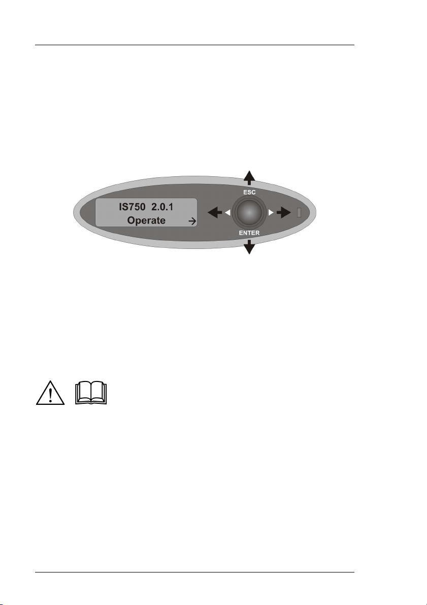
Front panel control of Imagestore 750 is achieved using a four-position
joystick in conjunction with prompts from the display.
Where reference is made to a joystick input the legend of the position will be
shown in lowercase italics (escape or enter) or by the arrow icons ⊳ and .
The two-line display provides a range of prompts in response to joystick
moves. Where reference is made to an actual display prompt this will be
shown italicised, e.g. Operate or Mix A Input.
These symbols denote ‘Refer to documentation’.
Page 8 Miranda Technologies Inc.
Page 9

Imagestore 750 User Manual Preface
Contacts
For technical assistance, please contact your nearest Miranda Technical
Support centre:
Americas (9:00am - 9:00pm EST)
Telephone +1-800-224-7882
Fax: +1-514-335-1614
techsupp@miranda.com
Europe, Middle East, Africa, UK (9:00am - 6:00pm GMT)
Telephone +44 (0) 1491 820222
Fax: +44 (0) 1491 820002
eurotech@miranda.com
France (9:00am - 5:00pm GMT+1)
Telephone +33 1 55 86 87 88
Fax: +33 1 55 86 00 29
eurotech@miranda.com
Asia (9:00am - 5:00pm GMT+8)
Telephone +852-2539-6987
Fax: +852-2539-0804
asiatech@miranda.com
China
Telephone: +86-10-5873-1814
asiatech@miranda.com
www.miranda.com
Miranda Technologies Inc. Page 9
Page 10

Preface Imagestore 750 User Manual
Manual Structure
Overview
The overview provides an introduction to the Miranda Technologies Inc.
Imagestore 750 for new users and describes the functions and features
offered by the product. It includes a simple technical concept of the unit and
details the optional modules that are available to enhance the unit's
capabilities.
Front Panel Operations
This section describes how to operate Imagestore 750 using the front-panel
controls. Each manual function, feature and parameter is fully described.
RCP Operations
This section provides an introduction to Miranda Technologies Ltd's Oxtel
Remote Control Panel (RCP). It identifies the user controls and explains how
they are used. It describes the way the panel may be used to control more
than one Imagestore unit through an Intelligent Panel Router (IPR). The full
range of remote control panel functions available when used with Imagestore
750 are detailed and a description is given of each feature.
Audio Mix files
The mix file is used to specify sets of audio sources or inputs to be mixed
together using certain rules and then assigning the result to a particular
destination or output. This section explains the function and terminology of
the mix file and how to create them.
Emergency Alert System
This section describes how to operate the Emergency Alert System.
Page 10 Miranda Technologies Inc.
Page 11

Imagestore 750 User Manual Preface
Graphics Co-Processor
This section describes how to configure the Imagestore 750 for use with a
Miranda Graphics Co-Processor, such as the Imagestore Intuition+ Graphics
Co-Processor and Miranda VertigoXG Graphics Processor.
Imagestore 750 Web Page
This section provides a description of the features available on the
Imagestore 750 Web Page, which is hosted on the unit.
Installation
This section contains details of the unit interconnections and interfaces. It
describes all the set-up procedures required for a successful installation
including reference source selection, internal timing and synchronisation setup.
Support
The support section describes the procedures for using the return-to-base
warranty. It explains how to contact the Miranda Technologies Inc. technical
support team and outlines a series of preliminary unit checks that should be
made prior to calling.
Imagestore Specifications
This appendix provides a summary of the specifications of Imagestore 750.
Standard Mixfiles
This section explains the operational differences implemented by each of the
Miranda Technologies supplied Audio Mix files.
Miranda Technologies Inc. Page 11
Page 12

Preface Imagestore 750 User Manual
Dolby Decode/Encode
This section contains information relating to the Imagestore 750 Dolby
options (Dolby E decode/encode and Dolby Digital (AC3) encode).
Up-Mix
This section contains information relating to the Imagestore 750 Up-Mix
option (stereo to 5.1-surround).
Software Update
Instructions on how to format a bootable USB drive and how to load the
latest software via the USB drive or Imagestore web page.
Glossary
This appendix contains a guide to the terms and abbreviations found within
this user guide.
Menu Tree
This appendix contains a listing of the current menu tree.
Index
This appendix provides blank pages that may be used to record useful unit
configuration data.
Page 12 Miranda Technologies Inc.
Page 13

Imagestore User Manual Table of Contents
Table of Contents
Preface 3
Warranty --------------------------------------------------------------------------- 3
Important Safety Notices ------------------------------------------------------- 4
Injury Precautions-------------------------------------------------------------- 4
Product Damage Precautions ---------------------------------------------- 5
Certifications and Compliances -------------------------------------------- 5
Scope of the Manual ------------------------------------------------------------ 7
Associated Publications ------------------------------------------------------ 7
Symbols and Conventions ----------------------------------------------------- 8
Contacts---------------------------------------------------------------------------- 9
Manual Structure --------------------------------------------------------------- 10
Overview ----------------------------------------------------------------------- 10
Front Panel Operations----------------------------------------------------- 10
RCP Operations-------------------------------------------------------------- 10
Audio Mix files ---------------------------------------------------------------- 10
Emergency Alert System--------------------------------------------------- 10
Graphics Co-Processor ---------------------------------------------------- 11
Imagestore 750 Web Page ------------------------------------------------ 11
Installation --------------------------------------------------------------------- 11
Support ------------------------------------------------------------------------- 11
Imagestore Specifications ------------------------------------------------- 11
Standard Mixfiles------------------------------------------------------------- 11
Dolby Decode/Encode ------------------------------------------------------ 12
Up-Mix -------------------------------------------------------------------------- 12
Software Update ------------------------------------------------------------- 12
Glossary------------------------------------------------------------------------ 12
Menu Tree --------------------------------------------------------------------- 12
Index ---------------------------------------------------------------------------- 12
Table of Contents 13
Miranda Technologies Inc. Page 13
Page 14

Table of Contents Imagestore 750 User Manual
Overview 35
Introduction-----------------------------------------------------------------------35
Applications ----------------------------------------------------------------------35
Concept ---------------------------------------------------------------------------36
Main Inputs / Outputs --------------------------------------------------------36
Block Diagram-----------------------------------------------------------------38
Video Architecture------------------------------------------------------------39
Video Standards ----------------------------------------------------------------40
Getting Started ------------------------------------------------------------------41
Applying Power ---------------------------------------------------------------41
Boot-Up Sequence -----------------------------------------------------------41
Facilities and Features --------------------------------------------------------42
Image Loading and Distribution -------------------------------------------42
Image Editing ------------------------------------------------------------------42
Transmission ------------------------------------------------------------------42
Animated Images -------------------------------------------------------------42
AB Mixer ------------------------------------------------------------------------44
Timing, Control and Automation ------------------------------------------44
Mechanical Bypass ----------------------------------------------------------44
Emergency Alert System ---------------------------------------------------44
2D DVE (PGM and PVW) --------------------------------------------------45
Clock Insertion ----------------------------------------------------------------45
Embedded Digital Audio Mixer --------------------------------------------46
Switching Dolby E Signals--------------------------------------------------46
Digital Audio Storage --------------------------------------------------------46
Options --------------------------------------------------------------------------47
Checking Installed Options-------------------------------------------------49
Front Panel Operations 51
Controls -------------------------------------------------------------------------51
Front Panel Display ----------------------------------------------------------51
Front Panel Tallies --------------------------------------------------------52
Escape and Enter Joystick Selections ----------------------------------52
Left and Right Joystick Arrows --------------------------------------------52
Opening Screen---------------------------------------------------------------53
Page 14 Miranda Technologies Inc.
Page 15

Imagestore 750 User Manual Table of Contents
Operate--------------------------------------------------------------------------- 54
Set Inputs ---------------------------------------------------------------------- 54
Set Inputs Menu Tree ---------------------------------------------------- 54
Pass SDI -------------------------------------------------------------------- 56
Colour Field 1 -------------------------------------------------------------- 56
Colour Field 2 -------------------------------------------------------------- 56
Colour Field 3 -------------------------------------------------------------- 56
Test Pattern 1 -------------------------------------------------------------- 56
Test Pattern 2 -------------------------------------------------------------- 56
Input Masks ------------------------------------------------------------------- 57
Input Masks Menu Tree ------------------------------------------------- 57
Left---------------------------------------------------------------------------- 59
Right-------------------------------------------------------------------------- 59
Top --------------------------------------------------------------------------- 59
Bottom ----------------------------------------------------------------------- 59
Colour Fields ------------------------------------------------------------------ 60
Colour Fields Menu Tree ------------------------------------------------ 60
Standard Colours --------------------------------------------------------- 61
Mix A Input -------------------------------------------------------------------- 62
Mix A Input Menu Tree -------------------------------------------------- 62
Mix B Input -------------------------------------------------------------------- 64
Mix B Input Menu Tree -------------------------------------------------- 64
AB Mixer ----------------------------------------------------------------------- 65
AB Mixer Menu Tree ----------------------------------------------------- 65
Cut AB ----------------------------------------------------------------------- 67
Cut To A--------------------------------------------------------------------- 67
Cut To B--------------------------------------------------------------------- 67
Fade AB --------------------------------------------------------------------- 67
Fade To A------------------------------------------------------------------- 67
Fade To B------------------------------------------------------------------- 67
Transition Type ------------------------------------------------------------ 67
Mix Rate--------------------------------------------------------------------- 67
V-Fade Colour ------------------------------------------------------------- 68
Standard Colours----------------------------------------------------- 68
Set Cut Mode -------------------------------------------------------------- 68
2D DVE (PGM) --------------------------------------------------------------- 69
2D DVE (PGM) Menu Tree --------------------------------------------- 69
Play Forward --------------------------------------------------------------- 70
Miranda Technologies Inc. Page 15
Page 16

Table of Contents Imagestore 750 User Manual
Play Backward--------------------------------------------------------------70
Run Sequence--------------------------------------------------------------71
DVE Mode -------------------------------------------------------------------71
Bypass-------------------------------------------------------------------71
None (Delay) -----------------------------------------------------------71
Enabled------------------------------------------------------------------71
DVE Configurations -------------------------------------------------------72
DVE 1 Input -----------------------------------------------------------------73
DVE 2 Input -----------------------------------------------------------------73
2D DVE (PVW)----------------------------------------------------------------74
2D DVE (PVW) Menu Tree----------------------------------------------74
DVE Configuration -----------------------------------------------------------76
DVE Config Menu Tree --------------------------------------------------76
K1 K2 DVE K3 K4 ---------------------------------------------------------76
K1 DVE K2 K3 K4 ---------------------------------------------------------76
DVE K1 K2 K3 K4 ---------------------------------------------------------77
DSK 1 ---------------------------------------------------------------------------78
Keyer Operations ----------------------------------------------------------79
Keyer Operations Menu Tree -------------------------------------------79
Cut Up/Down-----------------------------------------------------------81
Cut Up -------------------------------------------------------------------81
Cut Down ---------------------------------------------------------------81
Fade Up/Down---------------------------------------------------------81
Fade Up -----------------------------------------------------------------81
Fade Down -------------------------------------------------------------81
Fade Rate---------------------------------------------------------------81
Set Key Params -------------------------------------------------------82
Source ----------------------------------------------------------------84
Type -------------------------------------------------------------------84
Sense -----------------------------------------------------------------84
Masking --------------------------------------------------------------84
Disable----------------------------------------------------------------84
Setup------------------------------------------------------------------85
Left---------------------------------------------------------------------85
Right-------------------------------------------------------------------85
Top --------------------------------------------------------------------85
Bottom ----------------------------------------------------------------85
C, G & T (Clip, Gain & Transparency) ---------------------------85
Clip --------------------------------------------------------------------85
Page 16 Miranda Technologies Inc.
Page 17

Imagestore 750 User Manual Table of Contents
Gain ------------------------------------------------------------------ 85
Transparency------------------------------------------------------- 86
Typical CGT Values ---------------------------------------------- 86
Cut To/Fr Blk ---------------------------------------------------------- 86
Cut From Blk ---------------------------------------------------------- 86
Cut To Blk -------------------------------------------------------------- 86
Fade To/Fr Blk -------------------------------------------------------- 86
Fade From Blk -------------------------------------------------------- 86
Fade To Blk------------------------------------------------------------ 87
FTB Rate --------------------------------------------------------------- 87
Input Operations----------------------------------------------------------- 88
Input Operations Menu Tree ------------------------------------------- 88
Fill-1/Key-1 or Fill-2/Key-2 or Fill-3/Key-3 ---------------------- 88
Unload Input ----------------------------------------------------------- 88
Store Operations ---------------------------------------------------------- 89
Store Operations Menu Tree ------------------------------------------- 89
Load Image ------------------------------------------------------------ 90
Set Position ------------------------------------------------------------ 90
Horizontal ----------------------------------------------------------- 90
Vertical --------------------------------------------------------------- 90
Save Image ------------------------------------------------------------ 90
Unload Image --------------------------------------------------------- 90
Load Mode ------------------------------------------------------------- 90
Clean Load---------------------------------------------------------- 91
Cut Load------------------------------------------------------------- 91
Start Strap-------------------------------------------------------------- 91
Stop Strap-------------------------------------------------------------- 91
Start Timer ------------------------------------------------------------- 91
Stop Timer ------------------------------------------------------------- 91
Reset Timer------------------------------------------------------------ 91
Play Animation -------------------------------------------------------- 91
Restart Anim----------------------------------------------------------- 92
Stop Animation-------------------------------------------------------- 92
Stop Anim Now ------------------------------------------------------- 92
DSK 2--------------------------------------------------------------------------- 93
DSK 3--------------------------------------------------------------------------- 93
DSK 4--------------------------------------------------------------------------- 94
Preview Select---------------------------------------------------------------- 95
Preview Select Menu Tree---------------------------------------------- 95
Miranda Technologies Inc. Page 17
Page 18

Table of Contents Imagestore 750 User Manual
Clean Select -------------------------------------------------------------------96
Clean Select Menu Tree -------------------------------------------------96
Monitor Select -----------------------------------------------------------------97
Monitor Select Menu Tree -----------------------------------------------97
Audio ----------------------------------------------------------------------------99
Audio Menu Tree ----------------------------------------------------------99
Cut A/B ---------------------------------------------------------------- 110
Cut to A---------------------------------------------------------------- 110
Cut to B---------------------------------------------------------------- 110
Fade A/B -------------------------------------------------------------- 110
Fade to A-------------------------------------------------------------- 110
Fade to B-------------------------------------------------------------- 110
Toggle Silence ------------------------------------------------------- 110
Fade to Sil ------------------------------------------------------------ 110
Fade from Sil--------------------------------------------------------- 110
Toggle VO ------------------------------------------------------------ 111
Voice-over n------------------------------------------------------- 111
Fade up VO ---------------------------------------------------------- 111
Voice-over n------------------------------------------------------- 111
Fade down VO------------------------------------------------------- 111
Voice-over n------------------------------------------------------- 111
Preview Select ------------------------------------------------------- 111
Clean Select---------------------------------------------------------- 113
Monitor Select ------------------------------------------------------- 113
Input Shuffles -------------------------------------------------------- 114
Set Rates ------------------------------------------------------------- 115
Fade A/B ----------------------------------------------------------- 115
Fade to Sil --------------------------------------------------------- 115
Voice-over n------------------------------------------------------- 115
Voice-overs----------------------------------------------------------- 115
Duck----------------------------------------------------------------- 116
Preset --------------------------------------------------------------- 116
Easyplay -------------------------------------------------------------- 116
Store n -------------------------------------------------------------- 116
MD Preset ------------------------------------------------------------ 117
Processor n------------------------------------------------------- 117
GPI Output ------------------------------------------------------------------- 118
GPI Output Menu Tree ------------------------------------------------- 118
GPI Output------------------------------------------------------------ 119
Page 18 Miranda Technologies Inc.
Page 19

Imagestore 750 User Manual Table of Contents
Miscellaneous----------------------------------------------------------------120
Miscellaneous Menu Tree ---------------------------------------------120
GPI Delay -------------------------------------------------------------120
Emer To Air (Emergency To Air) --------------------------------121
Emer From Air (Emergency From Air) -------------------------121
EAS On ----------------------------------------------------------------121
EAS Off ----------------------------------------------------------------122
Setup-----------------------------------------------------------------------------123
Configuration-----------------------------------------------------------------123
Configuration Menu Tree-----------------------------------------------123
Import Config ---------------------------------------------------------124
Export Config---------------------------------------------------------125
Last Config------------------------------------------------------------125
Audio Setup ------------------------------------------------------------------126
Audio Setup Menu Tree ------------------------------------------------126
Audio Metering-------------------------------------------------------128
Meters 1 - 4 --------------------------------------------------------128
Meters 1 and 2 ----------------------------------------------------128
Follow Video----------------------------------------------------------128
A/B Mix--------------------------------------------------------------129
Fade-to-Black -----------------------------------------------------129
Easyplay------------------------------------------------------------129
Select Mixfile ---------------------------------------------------------129
Delays------------------------------------------------------------------130
GPI Setup---------------------------------------------------------------------131
GPI Setup Menu Tree---------------------------------------------------131
Input to GPI----------------------------------------------------------------133
GPI Channels --------------------------------------------------------134
Create a GPI Macro -----------------------------------------------------134
GPI Macro Command List ---------------------------------------------135
Set Inputs -------------------------------------------------------------135
Input Masks-----------------------------------------------------------135
Colour Fields ---------------------------------------------------------135
Mix A Input ------------------------------------------------------------135
Mix B Input ------------------------------------------------------------135
AB Mixer---------------------------------------------------------------135
2D DVE (PGM) ------------------------------------------------------135
2D DVE (PVW) ------------------------------------------------------135
Miranda Technologies Inc. Page 19
Page 20

Table of Contents Imagestore 750 User Manual
DSK 1 ------------------------------------------------------------------ 135
DSK 2 ------------------------------------------------------------------ 135
DSK 3 ------------------------------------------------------------------ 136
DSK 4 ------------------------------------------------------------------ 136
Preview Select ------------------------------------------------------- 136
Clean Select---------------------------------------------------------- 136
Monitor Select ------------------------------------------------------- 136
Audio ------------------------------------------------------------------- 136
GPI Output------------------------------------------------------------ 136
Miscellaneous-------------------------------------------------------- 136
Edit a GPI Macro--------------------------------------------------------- 136
Insert Before --------------------------------------------------------- 136
Delete ------------------------------------------------------------------ 137
Insert After ------------------------------------------------------------ 137
Output from GPI---------------------------------------------------------- 137
Create a GPI Output ---------------------------------------------------- 137
Clear a GPI Output ------------------------------------------------------ 139
Show GPI Inputs --------------------------------------------------------- 139
File Operations -------------------------------------------------------------- 140
File Ops Menu Tree ----------------------------------------------------- 140
Load Image---------------------------------------------------------------- 141
Erase Image -------------------------------------------------------------- 141
Load Audio ---------------------------------------------------------------- 141
Erase Audio --------------------------------------------------------------- 141
Conf To USB-------------------------------------------------------------- 141
Conf From USB ---------------------------------------------------------- 142
Diags Save ---------------------------------------------------------------- 142
Load Licences ------------------------------------------------------------ 142
Load Mixfile --------------------------------------------------------------- 142
Erase Mixfile -------------------------------------------------------------- 142
Input Status ------------------------------------------------------------------ 143
Input Status Menu Tree ------------------------------------------------ 143
A Input---------------------------------------------------------------------- 145
Video Standard ------------------------------------------------------ 145
Input Timing ---------------------------------------------------------- 145
Audio Type ----------------------------------------------------------- 146
B/C/D Input ---------------------------------------------------------------- 146
Fill-1/Key-1/Fill-2/Key-2 Input ----------------------------------------- 146
References ---------------------------------------------------------------- 146
Page 20 Miranda Technologies Inc.
Page 21

Imagestore 750 User Manual Table of Contents
Ext Ref Locked-------------------------------------------------------146
Source -----------------------------------------------------------------146
Standard---------------------------------------------------------------146
AES--------------------------------------------------------------------------147
Pair nL, Pair nR------------------------------------------------------147
Clocks-----------------------------------------------------------------------147
74 MHz Clk -----------------------------------------------------------147
54 MHz Clk -----------------------------------------------------------147
27 MHz Clk -----------------------------------------------------------147
Audio Module Status -------------------------------------------------------148
Audio Mod Stat Menu Tree --------------------------------------------148
Module n Status ----------------------------------------------------------148
Module n Type ------------------------------------------------------------149
System Information---------------------------------------------------------150
System Info Menu Tree-------------------------------------------------150
Serial Number ------------------------------------------------------------151
IP Address -----------------------------------------------------------------152
Hostname ------------------------------------------------------------------152
Network Mask-------------------------------------------------------------152
Gateway Add--------------------------------------------------------------152
NTP Server ----------------------------------------------------------------152
Op System-----------------------------------------------------------------152
File Sys Type -------------------------------------------------------------152
Animation Mem -----------------------------------------------------------153
Images Used --------------------------------------------------------------153
Disk Space Used---------------------------------------------------------153
Current MixFile -----------------------------------------------------------153
COM n Counters ---------------------------------------------------------153
RS232A Counters, RS232B Counters ------------------------------153
RS485 n Counters -------------------------------------------------------154
Time Zone -----------------------------------------------------------------154
Current Date --------------------------------------------------------------154
Current Time --------------------------------------------------------------154
Running Since ------------------------------------------------------------154
Temperature --------------------------------------------------------------154
PSUA 12V -----------------------------------------------------------------154
PSUB 12V -----------------------------------------------------------------154
SYS 5V ---------------------------------------------------------------------154
SYS 3.3V-------------------------------------------------------------------155
Miranda Technologies Inc. Page 21
Page 22

Table of Contents Imagestore 750 User Manual
SYS 2.5V ------------------------------------------------------------------ 155
SYS 1.8V ------------------------------------------------------------------ 155
SYS 1.2V ------------------------------------------------------------------ 155
DVE 12V ------------------------------------------------------------------- 155
DVE 2.5V ------------------------------------------------------------------ 155
DVE 1.8V ------------------------------------------------------------------ 155
DVE 1.2V ------------------------------------------------------------------ 155
PSU A ---------------------------------------------------------------------- 155
PSU B ---------------------------------------------------------------------- 155
FAN 1 SPEED ------------------------------------------------------------ 156
FAN 2 SPEED ------------------------------------------------------------ 156
FAN 3 SPEED ------------------------------------------------------------ 156
FAN 4 SPEED ------------------------------------------------------------ 156
FAN 5 SPEED ------------------------------------------------------------ 156
Main Board ID ------------------------------------------------------------ 156
I/O Board ID--------------------------------------------------------------- 156
DVE Board ID------------------------------------------------------------- 156
Store SPD ----------------------------------------------------------------- 156
Delay SPD----------------------------------------------------------------- 156
View Licences --------------------------------------------------------------- 158
Set Time ---------------------------------------------------------------------- 159
Set Time-of-Day Menu Tree ------------------------------------------ 159
Year ------------------------------------------------------------------------- 159
Month ----------------------------------------------------------------------- 159
Day -------------------------------------------------------------------------- 159
Hour------------------------------------------------------------------------- 160
Min -------------------------------------------------------------------------- 160
Sec -------------------------------------------------------------------------- 160
Self Tests --------------------------------------------------------------------- 161
Self Tests Menu Tree --------------------------------------------------- 161
DSK 1----------------------------------------------------------------------- 162
Image Border -------------------------------------------------------- 162
Animation Fill--------------------------------------------------------- 162
DSK 2 / DSK3 / DSK4 -------------------------------------------------- 163
EAS ------------------------------------------------------------------------- 163
Severity 1 ------------------------------------------------------------- 163
Severity 2 ------------------------------------------------------------- 163
Severity 3 ------------------------------------------------------------- 163
Prod Tests ----------------------------------------------------------------- 163
Page 22 Miranda Technologies Inc.
Page 23

Imagestore 750 User Manual Table of Contents
Logging------------------------------------------------------------------------164
Logging Menu Tree------------------------------------------------------164
Errors Only ----------------------------------------------------------------164
Media/Keying -------------------------------------------------------------164
Verbose --------------------------------------------------------------------164
Video Delay ------------------------------------------------------------------165
Video Delay Menu Tree ------------------------------------------------165
Program --------------------------------------------------------------------165
Preview ---------------------------------------------------------------------165
Clean Feed ----------------------------------------------------------------165
System Setup ----------------------------------------------------------------166
System Setup Menu Tree ----------------------------------------------166
Set Standard --------------------------------------------------------------170
Set Reference ------------------------------------------------------------170
Adjusting Reference Timing --------------------------------------171
Timing Delay Through the Imagestore 750 -------------------173
Pass Close Cap ----------------------------------------------------------174
Serial Comms -------------------------------------------------------------175
Baud Rate-------------------------------------------------------------175
Protocol ----------------------------------------------------------------175
Presmaster---------------------------------------------------------175
Intuition -------------------------------------------------------------175
EAS------------------------------------------------------------------176
RCP Classic -------------------------------------------------------176
Automation---------------------------------------------------------176
Serial Type------------------------------------------------------------176
Serial Level ----------------------------------------------------------------176
Strict -----------------------------------------------------------------176
Relaxed -------------------------------------------------------------177
Store Memory -------------------------------------------------------------177
Timecode Options -------------------------------------------------------178
Timecode Source ---------------------------------------------------178
Timecode Status ----------------------------------------------------178
Intuition Set----------------------------------------------------------------178
Def Keyer Assign----------------------------------------------------178
None-----------------------------------------------------------------178
DSK1 ----------------------------------------------------------------178
DSK2 ----------------------------------------------------------------179
DSK3 ----------------------------------------------------------------179
Miranda Technologies Inc. Page 23
Page 24

Table of Contents Imagestore 750 User Manual
DSK4---------------------------------------------------------------- 179
Keyer Release ------------------------------------------------------- 179
Disabled ------------------------------------------------------------ 179
Enabled------------------------------------------------------------- 179
Keyer Status --------------------------------------------------------- 179
Fill & Key Input ------------------------------------------------------ 179
Fill-1/Key-1 -------------------------------------------------------- 179
Fill-2/Key-2 -------------------------------------------------------- 180
Fill-3/Key-3 -------------------------------------------------------- 180
Hostname------------------------------------------------------------------ 180
IP Address----------------------------------------------------------------- 180
Network Mask ------------------------------------------------------------ 181
Gateway Address-------------------------------------------------------- 181
NTP Server---------------------------------------------------------------- 182
Logging Server ----------------------------------------------------------- 182
Local Logging------------------------------------------------------------- 183
Time Zone ----------------------------------------------------------------- 183
Software Reset ----------------------------------------------------------- 183
Restart System ----------------------------------------------------------- 183
Factory Reset------------------------------------------------------------- 184
Safe Shutdown ----------------------------------------------------------- 184
RCP Operations 185
Introduction--------------------------------------------------------------------- 185
Controls ------------------------------------------------------------------------- 187
Display -------------------------------------------------------------------------- 187
Push Button Switches ------------------------------------------------------- 187
Esc Key ----------------------------------------------------------------------- 187
Alphanumeric Keypad ----------------------------------------------------- 188
Setup Menu ------------------------------------------------------------------ 188
RCP Setup------------------------------------------------------------ 188
DSK3/DSK4 Control Setup --------------------------------------- 189
Video Menu ------------------------------------------------------------------ 190
Mixer ------------------------------------------------------------------------ 190
Transition Type ------------------------------------------------------ 190
Rate -------------------------------------------------------------------- 191
Page 24 Miranda Technologies Inc.
Page 25

Imagestore 750 User Manual Table of Contents
DSKn------------------------------------------------------------------------192
Input Source ----------------------------------------------------------192
Load File---------------------------------------------------------------193
Position File-----------------------------------------------------------194
Horizontal Crop ------------------------------------------------------195
Vertical Crop----------------------------------------------------------196
Save File --------------------------------------------------------------198
Clip Gain & Transparency-----------------------------------------199
Keying Modes --------------------------------------------------------200
Keying Rates ---------------------------------------------------------201
Fade to Black Rate ------------------------------------------------------202
Audio Menu ------------------------------------------------------------------203
Transitions -----------------------------------------------------------------203
A/B Mix-----------------------------------------------------------------203
Fade to Silence ------------------------------------------------------204
Voice Overs-----------------------------------------------------------205
Inputs -----------------------------------------------------------------------206
A, B, VO1, VO2 ------------------------------------------------------206
Outputs ---------------------------------------------------------------------207
Program ---------------------------------------------------------------207
Transitions --------------------------------------------------------------------208
Rate -------------------------------------------------------------------------209
Mixer ------------------------------------------------------------------------209
Selecting the source ------------------------------------------------209
Cut ----------------------------------------------------------------------210
Trans -------------------------------------------------------------------210
DSK 1 -----------------------------------------------------------------------211
Cut ----------------------------------------------------------------------211
Trans -------------------------------------------------------------------211
DSK 2 -----------------------------------------------------------------------211
DSK 3 -----------------------------------------------------------------------211
DSK 4 -----------------------------------------------------------------------212
Take----------------------------------------------------------------------------212
Black and Silence-----------------------------------------------------------212
Voice-Over 1 -----------------------------------------------------------------213
Voice-Over 2 -----------------------------------------------------------------213
Chan Sel ----------------------------------------------------------------------213
Audio Mix Files 215
Miranda Technologies Inc. Page 25
Page 26

Table of Contents Imagestore 750 User Manual
Introduction--------------------------------------------------------------------- 215
Mix Files ------------------------------------------------------------------------ 217
Sources ------------------------------------------------------------------------- 217
Gain Types --------------------------------------------------------------------- 218
ZERO_XP -------------------------------------------------------------------- 218
UNITY_XP-------------------------------------------------------------------- 218
A_DATA_XP/B_DATA_XP ----------------------------------------------- 219
A_XP/B_XP ------------------------------------------------------------------ 219
A_CUT_XP/B_CUT_XP -------------------------------------------------- 219
VO1_XP/VO3_XP ---------------------------------------------------------- 219
VO1_PREVIEW_XP/VO3_PREVIEW_XP --------------------------- 219
EPLAY_XP ------------------------------------------------------------------- 220
A_UNITY_XP/B_UNITY_XP --------------------------------------------- 220
VO1_UNITY_XP/VO3_UNITY_XP ------------------------------------- 220
A/B_PRESHUFFLE_UNITY_XP ---------------------------------------- 220
Output Gain Types ----------------------------------------------------------- 221
PROGRAM_GAIN ---------------------------------------------------------- 221
Destinations -------------------------------------------------------------------- 221
Mix File Commands ---------------------------------------------------------- 221
StartMix ----------------------------------------------------------------------- 222
AddToMix--------------------------------------------------------------------- 222
SetOutputGain -------------------------------------------------------------- 222
OutputMix--------------------------------------------------------------------- 222
EndMix ------------------------------------------------------------------------ 222
Simple mix structure ------------------------------------------------------- 223
Input Bunches --------------------------------------------------------------- 223
Enhanced Mix File Commands -------------------------------------------- 226
Input Bunch Profiles ------------------------------------------------------- 226
MixDown ---------------------------------------------------------------------- 227
Monitor Profiles ------------------------------------------------------------- 228
Input Source Names (AddToMix) ----------------------------------------- 229
Output Source Names (OutputMix) -------------------------------------- 232
Mixfile Mapping---------------------------------------------------------------- 234
Page 26 Miranda Technologies Inc.
Page 27

Imagestore 750 User Manual Table of Contents
Emergency Alert System 235
EAS Overview -----------------------------------------------------------------235
Imagestore EAS Option -----------------------------------------------------235
EAS Crawl Templates -------------------------------------------------------236
Triggering EAS ----------------------------------------------------------------238
Control of EAS via the Front Panel ---------------------------------------239
EAS Receivers --------------------------------------------------------------239
Baud Rates -------------------------------------------------------------------239
Load EAS (EAS On) -------------------------------------------------------239
Unload EAS (EAS Off)-----------------------------------------------------240
EAS Logs -----------------------------------------------------------------------240
Graphics Co-Processor 241
Imagestore Intuition Control ------------------------------------------------243
Control ---------------------------------------------------------------------------245
Automatic Keyer Management --------------------------------------------245
Front Panel Menu-----------------------------------------------------------246
Def Keyer Assign---------------------------------------------------------246
Keyer Release ------------------------------------------------------------246
Keyer Status --------------------------------------------------------------246
Fill & Key Input------------------------------------------------------------246
Keyer Management Example --------------------------------------------246
VertigoXG-----------------------------------------------------------------------247
Web Interface 249
Logging In-----------------------------------------------------------------------249
Home-----------------------------------------------------------------------------250
Overview ------------------------------------------------------------------------250
Configuration Templates ----------------------------------------------------251
Front Panel Mirror-------------------------------------------------------------252
Miranda Technologies Inc. Page 27
Page 28

Table of Contents Imagestore 750 User Manual
Logs------------------------------------------------------------------------------ 253
Media ---------------------------------------------------------------------------- 254
Backup Media --------------------------------------------------------------- 255
System Information----------------------------------------------------------- 255
System Reset------------------------------------------------------------------ 257
Tools ----------------------------------------------------------------------------- 258
Create Diagnostics File --------------------------------------------------- 258
Create USB Upgrade Media --------------------------------------------- 259
Create Device Capabilities File ----------------------------------------- 260
Upgrade------------------------------------------------------------------------- 260
Update Software ------------------------------------------------------------ 261
Full Re-initialisation -------------------------------------------------------- 262
Revert ------------------------------------------------------------------------- 264
Installation 267
Rack Mount Instructions ---------------------------------------------------- 267
Ventilation ---------------------------------------------------------------------- 268
Power Requirements -------------------------------------------------------- 268
Environment-------------------------------------------------------------------- 268
Restriction Access Location------------------------------------------------ 268
Imagestore 750 Rear Panel Connections ------------------------------ 269
Overview---------------------------------------------------------------------- 269
Serial Digital Video Inputs / Outputs ----------------------------------- 269
Video Relay Bypass ------------------------------------------------------- 270
REF IN ------------------------------------------------------------------------ 271
LAN 1-2 ----------------------------------------------------------------------- 272
Audio AES connector ------------------------------------------------------ 274
COM1 - COM4 -------------------------------------------------------------- 277
GPIO/LTC -------------------------------------------------------------------- 278
Connection of General Purpose Interfaces (GPIs) ----------------- 281
Input to GPI --------------------------------------------------------------- 281
Output from GPI---------------------------------------------------------- 281
Connection LTC------------------------------------------------------------- 281
Page 28 Miranda Technologies Inc.
Page 29

Imagestore 750 User Manual Table of Contents
Mains Input -------------------------------------------------------------------282
Support 283
Product Support ---------------------------------------------------------------283
Warranty and Non-Warranty Repairs ----------------------------------283
Obsolescence----------------------------------------------------------------283
Upgrades ---------------------------------------------------------------------283
Service Visits-----------------------------------------------------------------284
Equipment Loans -----------------------------------------------------------284
Training------------------------------------------------------------------------284
Web Page --------------------------------------------------------------------284
Returns Procedure------------------------------------------------------------284
Transit Packaging-----------------------------------------------------------285
Imagestore Specifications 287
SDI Inputs and Outputs ---------------------------------------------------287
Power Requirements-------------------------------------------------------287
Interfaces ---------------------------------------------------------------------287
Mechanical -------------------------------------------------------------------288
Environmental ---------------------------------------------------------------288
Oxtel RCP ----------------------------------------------------------------------289
Mechanical -------------------------------------------------------------------289
Environmental ---------------------------------------------------------------289
Power Requirements-------------------------------------------------------289
RTC Battery --------------------------------------------------------------------289
Standard Mixfiles 291
Introduction ---------------------------------------------------------------------291
Imagestore 2/3 Emulation Mixfiles ----------------------------------------296
is23.mix & is23eply.mix ---------------------------------------------------296
Program output meter tracking ---------------------------------------297
Voice-over preview meter tracking-----------------------------------297
12 channel pass-through -----------------------------------------------297
Group sensitive previewing --------------------------------------------297
Pass-through Mixfiles --------------------------------------------------------297
Miranda Technologies Inc. Page 29
Page 30

Table of Contents Imagestore 750 User Manual
16chn_emb_pass.mix ----------------------------------------------------- 297
16chn_AES_pass.mix ----------------------------------------------------- 298
32chn_AES_pass.mix ----------------------------------------------------- 298
16 Channel AB Mixfiles ----------------------------------------------------- 298
16chn_AB.mix --------------------------------------------------------------- 299
16chn_AB_eply.mix -------------------------------------------------------- 299
16chn_AES_AB.mix ------------------------------------------------------- 299
16chn_AES_AB_eply.mix ------------------------------------------------ 300
5.1 Channel Mixfiles --------------------------------------------------------- 300
Introduction------------------------------------------------------------------- 300
Mix Modes ----------------------------------------------------------------- 300
Versatile Voice-over Shuffling ---------------------------------------- 301
Preview Modes and Metering----------------------------------------- 301
Delay Banks for DVE Compensation ------------------------------- 301
10 Channel Pass-through --------------------------------------------- 302
5.1 Mixfile Variants --------------------------------------------------------- 302
5.1_dualVO.mix ---------------------------------------------------------- 302
5.1_VO_eply.mix--------------------------------------------------------- 302
5.1_AES_dualVO.mix -------------------------------------------------- 303
5.1_AES_VO_eply.mix ------------------------------------------------- 303
5.1_IntuitionVO.mix ----------------------------------------------------- 303
5.1 Mix Modes--------------------------------------------------------------- 303
Mode 1: Standard 5.1 AB mix ---------------------------------------- 303
Mode 2: Left and Right Copy ----------------------------------------- 305
Mode 3: Left, Right and Centre Copy------------------------------- 310
5.1 Mixfile Voice-over Topology and Operation --------------------- 313
Dual External Voice-overs --------------------------------------------- 313
Easyplay and External Voice-over----------------------------------- 317
6-channel External Voice-over (Intuition+) ------------------------ 321
7.1 Channel Mixfiles --------------------------------------------------------- 324
Introduction------------------------------------------------------------------- 324
Mix Modes ----------------------------------------------------------------- 324
Versatile Voice-over Shuffling ---------------------------------------- 325
Preview Modes and Metering----------------------------------------- 325
Delay Banks for DVE Compensation ------------------------------- 325
8 Channel Pass-through ----------------------------------------------- 325
7.1 Mixfile Variants --------------------------------------------------------- 326
Page 30 Miranda Technologies Inc.
Page 31

Imagestore 750 User Manual Table of Contents
7.1_dualVO.mix ----------------------------------------------------------326
7.1_VO_eply.mix ---------------------------------------------------------326
7.1_ AES_eply.mix ------------------------------------------------------326
7.1_IntuitionVO.mix------------------------------------------------------327
7.1 Mixfile Modes -----------------------------------------------------------327
Mode 1: Standard 7.1 AB mix-----------------------------------------327
Mode 2: AB Mix Left and Right Copy -------------------------------328
Mode 3: Left, Right and Centre Mix ---------------------------------329
7.1 Mixfile Voice-over Topology and Operation ---------------------329
Dual External Voice-over-----------------------------------------------329
Easyplay and External Voice-over -----------------------------------329
8-channel External Voice-over (Intuition+)-------------------------331
Test Mixfiles --------------------------------------------------------------------334
test_eply.mix -----------------------------------------------------------------334
testtone_all.mix--------------------------------------------------------------334
Dolby Decode/Encode 335
Introduction ---------------------------------------------------------------------335
Dolby Digital (AC3) ---------------------------------------------------------336
Dolby E ------------------------------------------------------------------------336
Dolby Metadata--------------------------------------------------------------336
Dolby Handling on Legacy Systems -----------------------------------337
Dolby Handling with Dolby Options Installed-------------------------339
Configurator Tool Overview ----------------------------------------------340
Main Features Overview ----------------------------------------------------341
Decode and Encode Combinations---------------------------------------342
Product Codes -----------------------------------------------------------------346
Dolby Carrier Board Code ------------------------------------------------346
Dolby Kit Codes -------------------------------------------------------------346
Dolby Upgrade Codes -----------------------------------------------------346
Example Product Codes --------------------------------------------------347
Technical Specifications-----------------------------------------------------349
Dolby Module Types -------------------------------------------------------349
Dolby Decode Module --------------------------------------------------349
Dolby E Encoder Module-----------------------------------------------350
Miranda Technologies Inc. Page 31
Page 32

Table of Contents Imagestore 750 User Manual
Dolby Digital Encoder Module ---------------------------------------- 350
Dolby Processing Times -------------------------------------------------- 352
Dolby Module Firmware Upgrading ------------------------------------ 353
Dolby Front Panel Display Items---------------------------------------- 353
Internal Metadata Sources -------------------------------------------- 353
Audio Module Status / Type------------------------------------------- 354
Input Audio Type--------------------------------------------------------- 354
Configuring Dolby via Route Manager----------------------------------- 355
MixFiles and Dolby Options ---------------------------------------------- 355
Configurator------------------------------------------------------------------ 356
Dolby Metadata --------------------------------------------------------------- 357
Program Configuration ---------------------------------------------------- 357
Metadata Sources ---------------------------------------------------------- 359
Metadata Destinations ---------------------------------------------------- 360
Metadata Routing----------------------------------------------------------- 360
5.1 Embedded SDI AB-Mixing – (No Metadata) ----------------- 361
Metadata Direct Routing ----------------------------------------------- 362
Metadata Indirect AB-Switched Routing --------------------------- 363
Metadata User-Defined Presets ---------------------------------------- 364
Metadata Parameters-------------------------------------------------------- 365
Metadata Tab---------------------------------------------------------------- 365
Metadata Type ----------------------------------------------------------- 365
Program Configuration ------------------------------------------------- 365
Pitch Shift ------------------------------------------------------------------ 365
Programs ------------------------------------------------------------------ 365
Modes & Levels Tab ------------------------------------------------------- 366
Description ---------------------------------------------------------------- 366
Bitstream Mode ---------------------------------------------------------- 366
Audio Coding Mode ----------------------------------------------------- 366
Center Mix Level --------------------------------------------------------- 367
Surround Mix Level------------------------------------------------------ 367
Dolby Surround Mode -------------------------------------------------- 367
Dialogue Normalization ------------------------------------------------ 367
Mix Level------------------------------------------------------------------- 368
Room Type ---------------------------------------------------------------- 368
Dolby Mix Mode ---------------------------------------------------------- 368
Lt/Rt Center Mix Level -------------------------------------------------- 369
Page 32 Miranda Technologies Inc.
Page 33

Imagestore 750 User Manual Table of Contents
Lt/Rt Surround Mix Level -----------------------------------------------369
Lo/Ro Center Mix Level ------------------------------------------------369
Lo/Ro Surround Mix Level ---------------------------------------------370
Dolby Surround EXTM Mode -------------------------------------------370
Dolby Headphone Mode -----------------------------------------------371
AD Converter Type ------------------------------------------------------371
Features Tab-----------------------------------------------------------------371
Low Frequency Effects -------------------------------------------------371
Copyright-------------------------------------------------------------------372
Original Bitstream --------------------------------------------------------372
High Pass Filter-----------------------------------------------------------372
Bandwidth Low Pass Filter --------------------------------------------372
LFE Low Pass Filter -----------------------------------------------------372
Surround 90 Degrees Phase ------------------------------------------372
Surround Attenuation ---------------------------------------------------373
RF Pre-emphasis --------------------------------------------------------373
Compression Tab -----------------------------------------------------------373
Profile -----------------------------------------------------------------------374
Dynamic Range Tab -------------------------------------------------------374
System Delays-----------------------------------------------------------------375
Dolby Delays -----------------------------------------------------------------375
Metadata Delays ------------------------------------------------------------376
Video Delay Blocks---------------------------------------------------------376
Audio Delay Blocks---------------------------------------------------------376
Automation Control -----------------------------------------------------------378
Internal Metadata Sources -----------------------------------------------378
Dolby E Encoder Modules ------------------------------------------------379
Dolby Digital Encoder Modules------------------------------------------380
Dolby Decoder Modules---------------------------------------------------380
Up-Mix 381
Introduction ---------------------------------------------------------------------381
Up-Mix Configurations -------------------------------------------------------382
Product Codes -----------------------------------------------------------------383
Up-Mix Kit Code-------------------------------------------------------------383
Up-Mix Upgrade Code -----------------------------------------------------383
Miranda Technologies Inc. Page 33
Page 34

Table of Contents Imagestore 750 User Manual
Technical Specifications ---------------------------------------------------- 384
Passthrough Mode --------------------------------------------------------- 384
Up-Mix Mode ---------------------------------------------------------------- 385
From Metadata Mode------------------------------------------------------ 385
AutoMAXTM Mode ---------------------------------------------------------- 386
Up-Mix Processing Times ------------------------------------------------ 386
Up-Mix Module Firmware Upgrading ---------------------------------- 387
Configuring Up-Mix via Route Manager --------------------------------- 388
Configurator Tool ----------------------------------------------------------- 388
Connecting Up-Mix Modules--------------------------------------------- 389
Connecting Metadata to Up-Mix Modules ---------------------------- 389
Metadata ------------------------------------------------------------------------ 391
Metadata Monitoring/Processing --------------------------------------- 391
Metadata User-Defined Presets ---------------------------------------- 391
Automation Control----------------------------------------------------------- 392
Up-Mix Modules------------------------------------------------------------- 392
Software Update 393
Files ------------------------------------------------------------------------------ 393
Update Methods -------------------------------------------------------------- 393
Update via Bootable USB Key ------------------------------------------ 393
Update via Imagestore Web Page ------------------------------------- 394
Software Update Recovery----------------------------------------------- 394
Notes on Upgrading from v1.14.1 to v2.0 ---------------------------- 395
Glossary 399
Menu Tree 401
Index 419
Page 34 Miranda Technologies Inc.
Page 35

Imagestore 750 User Manual Overview
Overview
Introduction
This introduction provides a basic overview of the concept of the unit and
includes instructions for getting started.
An extensive range of options and upgrades are available for Imagestore 750
and this section describes the purpose and features of each enhancement.
More detailed and specific information regarding operation, configuration,
installation, the web interface, operation with Dolby and support are provided
in later sections.
Imagestore 750 (Product code IS-750) is part of Miranda Technologies Inc.'s
professional broadcast equipment range of products and its primary use is to
insert up to four logos into either SD-SDI or HD-SDI digital video signals.
The capabilities of this 1RU unit include simple logo insertion, still and
animated images. The Imagestore 750 can be purchased with Dolby options
to enable enhanced audio features.
Applications
Imagestore 750 is typically used to mix between different program feeds and
to insert a still or animated logo, channel identification, a programme
schedule, an advertisement, an emergency image, or a combination of any
four of those. Each of these resources may be brought on-air from the image
library of up to 4000 images. Alternatively, up to three separate external 'live'
fill and key signals (from a character generator, or a still/animation store) can
be directly inserted into the SD-SDI or HD-SDI signal via any of the four
keying layers.
Imagestore 750 is also fully compatible with the Presmaster Control System
and panel to create a Master Control environment.
Miranda Technologies Inc. Page 35
Page 36

Overview Imagestore 750 User Manual
Concept
Imagestore 750 is set up for operation where an A/B video mixer is followed
by four keyers arranged in series as shown in the dual-channel arrangement
below.
PROGRAM CHANNEL
A/B
MIXER
A/B
MIXER
KEYER1 KEYER2 KEYER3 KEYER4
PREVIEW CHANNEL
KEYER1 KEYER2 KEYER3 KEYER4
IS750 A/B MIXER and KEYERS
This basic configuration allows four images to be keyed simultaneously, but
independently, over the background video, with Program and Full Preview
outputs.
Main Inputs / Outputs
The Imagestore 750 has the following IO connections:-
• 8 video BNC inputs
• 4 video BNC outputs
• 16 channel AES in and out (i.e. 32 mono channels in, 32 mono out)
• 1 BNC Analogue Reference Input (SD bi-level or HD tri-level)
• 2 RJ45 Ethernet 100baseT network ports
Page 36 Miranda Technologies Inc.
Page 37

Imagestore 750 User Manual Overview
• 4 RJ45 Serial Comms Ports
• 4 RS485 Metadata inputs/outputs
• GPIO/LTC port
• Video Relay Bypass across 2 of the Outputs
These Input / Output Connections are shown in the diagram below:
SCSI-style connector
AES IN OUT
BNCs
BNCs
A
B
C (or Fill3)
D (or Key3)
Fill 1
Key 1
Fill 2
Key 2
Ref
GPIO / LTC
25wD
LAN 1
EtherNet
IS750
RJ45s
LAN 2
PGM OUT
BNCs
PVW OUT
CLN OUT
MON OUT
COM1 - 4
IS750 I/O Connections
Miranda Technologies Inc. Page 37
Page 38

Overview Imagestore 750 User Manual
Block Diagram
Main signal paths within the Imagestore 750 unit are shown below:
RELAY BYPASS
AUDIO 16 Ch AES IN
HD
SCSI
CONNR
AIN
BNC
BIN
BNC
CIN
BNC
DIN
BNC
FILL1
KEY1
BNC
FILL2
KEY2
BNC
Eth Net
Eth Net
RJ45
LINE FIFOS
LINE FIFOS
Video
LINE FIFOS
LINE FIFOS
LINE FIFOS
LINE FIFOS
LINE FIFOS
LINE FIFOS
Fill/Key
Fill/Key
STORES 1-4
HDDCPU
Store
Store
Store
Keys
ROUTER
VIDEO INPUT
Fill/
KEYER LOADING
AUDIO PROCESSING
VIDEO PGM CHANNEL
VIDEO PVW CHANNEL
Fill/
Keys
AUDIO 16 Ch AES OUT
SELECT
CLEAN FEED
SELECT
MONITOR
HD
SCSI
CONNR
EMBD
AUDIO
MUX
PGM OUT
PVW OUT
CLN FEED
MONITOR OUT
BNC
Video
BNC
BNC
BNC
REF IN
BNC
IS750 Block Diagram – Main Signal Paths
There are line FIFOs on each SDI video input, feeding 2 Video Channel
Blocks (Program and Preview) and one parallel Audio Processing block.
Each video channel has and AB Mix and 4 keyers which may be fed from up
to 3 external Fill/Keys or one of 4 internal stores and an optional dualchannel DVE.
Still (.oxt), animated and Easytext (.oxa) images are typically stored in the
unit's storage library (compact flash or hard disk, depending upon the option
purchased) and then loaded into the internal stores. Images may be added to
the library using a USB stick but the files must be in an appropriate format.
Miranda Technologies Inc.'s Media Conversion Software is designed for this
purpose and is supplied with each Imagestore 750.
An Ethernet interface provides for the rapid loading of images and
animations over a 100BaseT network using Media Conversion Software
Page 38 Miranda Technologies Inc.
Page 39

Imagestore 750 User Manual Overview
(MCS). This interface also enables the transfer of images between a PC
workstation and Imagestore using Miranda Technologies Inc.'s Vertigo
Xplorer product. This software provides for transfer and management of stillimages and animations. Files may also be transferred using a secure FTP
program.
A fail-safe mechanical Video Relay Bypass option is available that directly
connects the A and C video input sources (see block diagram below) to the
program and preview outputs in the event of a power supply problem.
Video Architecture
Each of the 2 video channel blocks within the Imagestore 750 contains an AB
Mixer and 4 Keyers, overlaying either internal or external media onto
background video (from 4 stores and/or up to 3 external Fill/Key inputs).
The video architecture is depicted below:
There is a DVE option that equips each video channel with a dual-channel
DVE. The DVE may be inserted at more than one point in the Keyer chains.
Miranda Technologies Inc. Page 39
Page 40

Overview Imagestore 750 User Manual
Additionally, Clean Feed and Monitor outputs allow various internal “nodes”
to be accessed including between keyers on the PGM channel for partially
branded output.
Audio processing is done in parallel.
Video Standards
Imagestore 750 supports SMPTE 259M 270Mb/s and SMPTE 292M
1.485Gb/s at the following resolutions:
SD 525i/59.94 Hz SMPTE 259M-1997
625i/50 Hz SMPTE 259M-1997
HD 1920 x 1080i/59.94 Hz SMPTE 274M 1998
1920 x 1080i/50 Hz SMPTE 274M 1998
1280 x 720/59.94 Hz SMPTE 296M 2001
1280 x 720/50 Hz SMPTE 296M 2001
Pixels
per
Standard
SMPTE
259M
525i59.94 720 486 30/1.001
625i50 720 576 25
SMPTE
274M
1920 x
1080/
59.94/2:1
1920 x
1080/
50/2:1
SMPTE
296M
1280 x
720/ 59.94
1280 x
720/ 50
active
line
(S/AL)
1920 1080 30/1.001
1920 1080 25
1280 720 60/1.001
1280 720 50
Active
lines
per
frame
Frame
rate
(Hz)
Scanning
format
2:1
interlaced
2:1
interlaced
2:1
interlaced
2:1
interlaced
1:1
Progressive
1:1
Progressive
Interface
sampling
clock
frequency
Fs (MHz)
13.5MHz 858 525
13.5MHz 864 625
74.25/1.001 2200 1125
74.25 2640 1125
74.25/1.001 1650 750
74.25 1980 750
Clock
periods
per
total
line
(S/TL)
Total
lines
per
frame
Page 40 Miranda Technologies Inc.
Page 41

Imagestore 750 User Manual Overview
Getting Started
Applying Power
Before applying power, ensure that the USB port does not contain a USB
stick. Each of the two power supply units (PSU) on the Imagestore 750
contains a power switch accessible by removing the front facia. The product
should be connected to the mains via an appropriate circuit breaker on each
circuit.
Boot-Up Sequence
Once power is applied, Imagestore 750 will boot automatically and the
normal complete boot process takes about 50 seconds (approx 90 seconds
after a software upgrade).
Before booting normally, the unit first checks to see if there is a USB stick in
the USB port and, if it finds one, it will attempt to boot from that disk.
Miranda Technologies Inc. issues specialised USB sticks for use as part of
the software upgrade boot-up sequence. No other USB stick should ever be
inserted. The upgrade procedure is covered later in this manual.
The normal boot sequence is complete when the following top level "bootup" menu appears on the front panel display.
Note: When a restart is required to change settings such as the video
standard, then a Software Reset can be used. Since this option
will usually complete in approximately 16 seconds it is much
faster than Restart System.
Miranda Technologies Inc. Page 41
Page 42

Overview Imagestore 750 User Manual
Facilities and Features
Image Loading and Distribution
The entry-level Imagestore 750 provides storage for up to 4000 full-screen
images with their associated keys. Each animated clip is counted as one
single image stored in the library. With large or long duration animations
(where the total pixel count of the animation exceeds one full-screen frame)
the total number of full screen frames used counts towards the permitted
maximum of full-screen images in the library.
Images (.oxt), animations and Easytext (.oxa) files saved to a USB stick from
Miranda Technologies Inc.'s Media Conversion Software (or other Miranda
Technologies Inc. units) can be loaded via a USB key or network transfer.
Note that to save or load media to/from a USB stick, the USB stick needs to
have been DOS formatted.
Miranda Technologies Inc. also provides an image transfer and management
system for Imagestore 750. The Xplorer software uses a local area network to
connect the workstation to a number of Miranda Technologies Inc.'s image
and audio insertion products. Details of Xplorer are contained in a separate
manual user guide.
Image Editing
The image editor permits an operator to position an image/animation (both
horizontally and vertically), mask the image/animation and adjust the clip,
gain and transparency levels prior to transmission.
Transmission
Once prepared, an image/animation can be saved in the image library and
sent to air using fade and cut transitions.
Animated Images
Imagestore 750 provides image animation, for applications such as moving
logos, messages and emergency images. The image motion system provides
Page 42 Miranda Technologies Inc.
Page 43

Imagestore 750 User Manual Overview
storage and live playout for up to 4000 full or part-screen images of variable
duration.
The maximum animation length is dependent upon the screen-size of the
images, the playout memory installed in the Imagestore 750 (512MB or 2GB)
and the amount of that memory allocated to the associated keyer.
There are four video stores, which may be used to hold text, stills or moving
logos. The images may be any size up to full screen. Stored images and their
associated keys are stored and processed at 10 bit resolution (unless the
image is stored without key to save space in which case it is stored at 8 bit
resolution.)
The time of larger animations, up to full screen, is reduced proportionally to
the area used. Areas are evaluated each frame so animations may change in
size with no penalty.
With 128MB of playout memory per store, a logo of ¹/64 screen size can be
animated for just over half a minute. Larger screen sizes or smaller playout
memory sizes affect the maximum animation time pro rata.
Standard Rate Frame Rate MB / Frame Max No. of Frames
1080i 59.94
29.97 7.91
Duration (s) 1/16th frame >
1/64th frame >
Memory Allocated
128 256 512 1024
16.1 32.2 64.4 128.8
8.6s 17.2s 34.4s 68.8s
34.3s 68.8s 137.6s 275.2s
Moving images are constructed from component images using the Animation
Builder software provided as part of the Media Conversion Software (MCS)
package supplied with Imagestore 750.
Component images are imported into the animation builder utility from 32-bit
Targa image files thus allowing components to originate from almost any
computer graphics system.
Miranda Technologies Inc. Page 43
Page 44

Overview Imagestore 750 User Manual
AB Mixer
The integral AB Mixer video switcher is designed to be fed by any of the
unit’s input sources or by an external router under automation control. The
mixer provides cut, cross and V-fade transitions with variable fade rates.
Timing, Control and Automation
Imagestore is designed to be easy to install. One line FIFO’s are provided on
each input for simplified system timing.
Other valuable set-up and control features include a menu-driven front panel
display, a General Purpose Interface (GPI) macro editor and a facility to load
(or save) configuration settings from (or to) a USB stick.
Imagestore 750 is highly suited to automated broadcast environments and
remote control options include RS422/RS232, as well as GPI.
Mechanical Bypass
In the event of power loss to the Imagestore 750, or failure of both internal
power supplies, the mechanical video relay bypass routes the serial digital
“background signal” “A In” directly to the Program output “PGM” and “C
In” to Preview output “PVW”.
This feature is an emergency failsafe and is completely non-synchronous in
operation. During boot-up, the bypass is maintained until Imagestore 750 is
fully operational. At switch-over a glitch in the video is to be expected.
Emergency Alert System
Imagestore 750 supports Emergency Alert Systems providing the relevant IS750-EAS licence is installed. The two supported EAS receivers are:
• Sage ENDEC Model 1822
• TFT EAS 911T
To configure a communication port to accept the EAS data stream refer to the
Serial Comms Setup section on page 176. For more information about EAS
please refer to page 235.
Page 44 Miranda Technologies Inc.
Page 45

Imagestore 750 User Manual Overview
2D DVE (PGM and PVW)
Both of the 2D DVE licence options provide the Imagestore 750 with
independent control of DVE sequences on Program (PGM) and Preview
(PVW) channels. The IS-750-DVE option enables a single DVE window per
channel, and the IS-750-DVE-DUAL option enables two DVE windows per
channel.
These options are capable of digital video effects on any of the input video
streams or AB Mixer output, making them ideal for picture-in-picture
applications such as over the shoulder news transitions, as well as squeezes
for credits, news flashes, sports results and schedules.
Clock Insertion
The Bugclock option (IS-750-Clock) allows Imagestore 750 to insert
customised in-vision clocks. A wide range of clocks and timers can be
generated, with hour, minute and second indications. Fully customised clocks
can be produced offline using the Clock Builder application (part of the
Media Conversion Software (MCS) package). Bugclock can be locked to
station LTC or VITC timecode. Clocks are loaded, previewed, positioned and
keyed in the same way as animations and static logos.
Bugclock images behave like all other images with respect to positioning,
transparency and masking controls. Previewing behaviour is the same as with
other clips and images and will show the clock running where appropriate
All existing GPI and automation commands, that apply to still images and
animations, function identically for clocks.
Bugclocks like other images use a single keying layer. This means that a
clock can be previewed while a different clock is shown on program.
Miranda Technologies Inc. Page 45
Page 46

Overview Imagestore 750 User Manual
Embedded Digital Audio Mixer
The optional Easysound digital audio mixer (IS-750-Audio6 or IS-750Audio16) can be enabled within Imagestore 750 and is designed to add voiceovers, jingles and other audio inserts over a program soundtrack at
transmission. Easysound can also accept audio from AES/EBU sources, as
well as embedded audio from the Imagestore's background video input. The
mixes are available on AES/EBU outputs and can also be re-embedded into
the SDI program output.
Switching Dolby E Signals
When operating in a progressive video standard (either 720p at50Hz or 720p
at 59.94Hz) and switching Dolby E signals, the Imagestore 750 must be
given an interlaced reference input – (1080i tri-level or SD bi-level analogue
reference) – and the Dolby E data must be aligned to this. This is because
Dolby E data is locked to the interlaced frame.
• 720p @ 59.94Hz = 59.94 Hz frame rate
• 1080i @ 59.94Hz = 29.97 Hz frame rate
This applies to all Imagestore 750 units that receive Dolby audio data,
whether or not any Dolby decode/encode options are enabled. Units without
Dolby options enabled are able to cut-switch between Dolby data streams,
with the transition occurring at the mid-point of an AB mix.
Digital Audio Storage
Easyplay options (IS-750-EP2 or IS-750-EP8) allow digital audio storage and
playout for Imagestore 750. With Easyplay, broadcasters can associate
sounds to image files, creating a whole new range of possibilities for musical
logos and sound enhanced captions. Easyplay requires the Easysound option
to be enabled and the system may be networked with the Media Distribution
System.
Page 46 Miranda Technologies Inc.
Page 47

Imagestore 750 User Manual Overview
Options
Status information regarding the options included with each Imagestore 750
can be accessed from the front panel display, using the panel control keys as
described later in this guide.
The following table lists the options with their identifying codes and briefly
describes the purpose.
Option
IS-750
IS-750-LOGO
IS-750-DVE
IS-750-DVE-DUAL
IS-750-Audio6
IS-750-Audio16
IS-750-EAS
IS-750-EP2
IS-750-EP8
IS-750-ET
IS-750-Clock
IS-750-MEM-2GB
IS-750-HDD
IS-750-DOLBY-CARRIERBOARD
Description
Imagestore 750 (AB inputs, 3 x Fill/Key
(includes CD inputs), AB mix, PGM, PVW,
Clean Feed, Monitor Feed, 512MB of stores
memory, SD and HD video standards)
Imagestore 750 LOGO Inserter (A input only,
2 x Fill/Key, PGM, PVW, 512MB of stores
memory, SD and HD video standards)
Single Channel DVE (PGM and PVW)
Dual Channel DVE (PGM and PVW)
Audio: 1 Group Embedded, 6 AES in, 6 AES
out
Audio: 4 Groups Embedded, 16 AES in, 16
AES out
Emergency Alert System with one AES in
Easyplay Stereo
Easyplay Eight Channels
Easytext
Bugclock
Stores memory: 2GB option
Internal media storage hard disk drive kit.
(Software and operating system reside on the
Compact Flash).
IS-750 Dolby Carrier Board. Recommended
kits to populate the carrier board are listed
below. Extra module upgrades may be
purchased up to a total of four modules.
Miranda Technologies Inc. Page 47
Page 48

Overview Imagestore 750 User Manual
Option
IS-750-DOLBY-DEC2
IS-750-DOLBY-DEC2-ENCE
IS-750-DOLBY-DEC2-ENCD
IS-750-DOLBY-ENCE
IS-750-DOLBY-ENCD
IS-750-UMX
IS-750-DOLBY-DEC-UPG
IS-750-DOLBY-ENCE-UPG
IS-750-DOLBY-ENCD-UPG
IS-750-UMX-UPG
Description
Two Dolby decoder modules
Two Dolby decoder modules + Dolby E
encoder module
Two Dolby decoder modules + Dolby Digital
(AC3) encoder module
Dolby E encoder module
Dolby Digital (AC3) encoder module
Up-Mix module
+1 Dolby E decoder upgrade
+1 Dolby E encoder upgrade
+1 Dolby Digital (AC3) encoder upgrade
+1 Up-Mix module upgrade
The Imagestore 750 LOGO is a branding-only product. From a hardware
perspective, it is identical to the standard Imagestore 750; however the
following features are disabled:
• AB mixing
• C/D inputs (Fill-3/Key-3)
• Clean Feed
• Monitor Feed
If these features need to be enabled at a future date is possible to upgrade to a
standard Imagestore 750 by purchasing the appropriate licences.
The IS-750-Audio6-75/110 and IS-750-Audio16-75/110 options include an
appropriate audio break-out cable hardware option – (product codes ABT-3232-D75 and ABT-32-32-D110). These comprise of a SCSI connector cable
(pin-out described on page 274) and a 1RU break-out box which allows easy
connection of 75R or 110R AES.
If the IS-750-EAS option is purchased without the IS-750-Audio6 or IS-750Audio16 option, then a stereo audio break-out cable (product code 1872-
Page 48 Miranda Technologies Inc.
Page 49

Imagestore 750 User Manual Overview
9100-100) is shipped with the unit. This comprises of a SCSI connector cable
to a single XLR for one stereo pair voice-over capability.
The Dolby modules (Dolby decode, Dolby E encode, Dolby Digital (AC3)
encode) and Up-Mix module options require that a Dolby carrier board also
be fitted. Whist the carrier-board and module options may be retro-fitted to
older Imagestore 750 units, please note if the RS485 ports are not present
then metadata input/output will not be possible via these ports.
Checking Installed Options
The Imagestore 750 can display the internal options installed from the front
panel display.
From the opening screen press the right arrow key to display Setup then
press enter to display the Setup menu.
Press the right arrow key until View Licences appears on the second line of
the display then press enter. Repeatedly pressing the key will now cycle
the display through a list of the fitted options. When completed, press the
escape key a few times until the boot-up menu reappears.
License Code Option
AB Mixer A/B video mixer
C & D Inputs C/Fill-3 and D/Key-3 Inputs
Emergency Alert Emergency Alert System (EAS)
Easytext Easytext Character Generator
2D DVE:1 1 channel DVE on PGM and PVW
2D DVE:2 2 channel DVE on PGM and PVW
Bugclock Analogue and Digital Clocks
Easysound Digital Audio Mixer
Easyplay:2 Digital Audio Storage and Playout (stereo)
Easyplay:8 Digital Audio Storage and Playout (8 channel)
Audio Embed:1 Audio Embedding on channels 1-4
Miranda Technologies Inc. Page 49
Page 50

Overview Imagestore 750 User Manual
Audio Embed:4 Audio Embedding on Channels 1-16
Standard:1 SD Standards (NTSC and PAL)
Standard:2 HD Standards (1080i/720p at 59.94Hz/50Hz)
Standard:3 SD and HD Standards
Store Mem:512 Total Store Memory 512MB
Store Mem:2048 Total Store Memory 2GB
LOGO Imagestore 750 LOGO Inserter
Clean Feed Clean Feed
Monitor Feed Monitor Feed
Dolby Dec:n n x Dolby decoder modules (where n is 1 to 4)
DolbyE Enc:n n x Dolby E encoder modules
DolbyD Enc:n n x Dolby Digital (AC3) encoder modules
Upmix:n n x Up-Mix modules
Note: C & D Inputs, clean feed and monitor feed are enabled by
default for the Imagestore 750. They are disabled for the
Imagestore 750 LOGO Inserter.
Page 50 Miranda Technologies Inc.
Page 51

Imagestore 750 User Manual Front Panel Operations
Front Panel Operations
This section of the manual explains, on a task-by-task basis, the operation of
an Imagestore 750 using only the front panel controls. Each task is fully
detailed, making reference to other sections unnecessary.
Controls
All Imagestore 750 operational and configuration features can be monitored
and controlled from the front panel of the unit using the joystick and display.
A simple menu-driven procedure provides access to the operational,
configuration and set-up options.
The front panel of Imagestore 750 contains a USB port, a four-position
joystick and a front panel LCD display. Local control of the unit is "menu
driven" using a combination of joystick movements together with options
displayed on the front panel. Joystick up is identified on the panel as escape
and joystick down is identified as enter. Left and right joystick moves ⊳
are used to move a cursor left and right accordingly to select menu options.
To the right of the Joystick is a small hole, behind which there is a button
used to reset the system (not recommended) or perform a software update
recovery (see page 394).
Front Panel Display
The alphanumeric front panel display is divided into two separate lines.
• The upper row of characters indicates the function
• The lower row indicates the current selection and any optional
configuration changes that are available.
Miranda Technologies Inc. Page 51
Page 52

Front Panel Operations Imagestore 750 User Manual
Where there are more options available than there is room for on the display,
the symbols and are used to indicate that other options exist to the left
and right respectively. Using the appropriate joystick move ⊳ will reveal
those options.
If an option is not licensed, e.g. 2D DVE, it will not be displayed on the front
panel menu.
Front Panel Tallies
To highlight the state of either the AB Mixer (video/audio) or the keyers,
additional symbols are shown on the top line of the front panel display at the
right hand edge. These symbols represent:
A Source A
B Source B
- Intermediate state, transition being processed.
↑ Image/voice-over keyed up (to air)
↓ Image/voice-over keyed down (from air)
B Fade to Black
S Fade to Silence
Escape and Enter Joystick Selections
Selecting escape is used to proceed to a menu option closer to the boot-up
menu. Successive pressing of escape will bring the display to the start-up
menu.
Selecting enter is used to accept the menu item currently shown as selected
by being enclosed in brackets.
Left and Right Joystick Arrows
Left and right joystick arrows ⊳ may be used to index left and right
respectively along a displayed menu branch to select a function. When a
selection of parameters is offered, these keys may be used to select a
variable. Where a single value is displayed the left arrow may be used to
reduce the displayed value and the right arrow may be used to increase it.
Page 52 Miranda Technologies Inc.
Page 53

Imagestore 750 User Manual Front Panel Operations
Opening Screen
The Imagestore 750 menu has two branches:
• Operate
• Setup
From the opening screen with Operate displayed press enter.
Note: If the unit is purchased as an Imagestore 750 LOGO Inserter
then the front panel will show ‘IS750L 2.0.1’.
Miranda Technologies Inc. Page 53
Page 54

Front Panel Operations Imagestore 750 User Manual
Operate
Set Inputs
Select Operate, Set Inputs.
Set Inputs Menu Tree
Operate
Set Inputs
A
Pass SDI
Colour Field 1
Colour Field 2
Colour Field 3
Test Pattern 1
Test Pattern 2
B
Pass SDI
Colour Field 1
Colour Field 2
Colour Field 3
Test Pattern 1
Test Pattern 2
C
Pass SDI
Colour Field 1
Colour Field 2
Colour Field 3
Page 54 Miranda Technologies Inc.
Page 55

Imagestore 750 User Manual Front Panel Operations
Test Pattern 1
Test Pattern 2
D
Pass SDI
Colour Field 1
Colour Field 2
Colour Field 3
Test Pattern 1
Test Pattern 2
Fill-1
Pass SDI
Colour Field 1
Colour Field 2
Colour Field 3
Test Pattern 1
Test Pattern 2
Key-1
Pass SDI
Colour Field 1
Colour Field 2
Colour Field 3
Test Pattern 1
Test Pattern 2
Fill-2
Pass SDI
Colour Field 1
Colour Field 2
Colour Field 3
Test Pattern 1
Test Pattern 2
Key-2
Pass SDI
Colour Field 1
Colour Field 2
Colour Field 3
Test Pattern 1
Test Pattern 2
Miranda Technologies Inc. Page 55
Page 56

Front Panel Operations Imagestore 750 User Manual
The factory default setting for each input is Pass-SDI, although any of the
three colour fields or two test patterns can be selected instead.
Using the front panel control joystick controls (⊳ enter) select the input
you wish to modify and select the setting that you wish this input to take.
Pass SDI
Selects the incoming SDI signal to be used for the selected input.
Colour Field 1
Selects the first colour field to be used for the selected input.
Colour Field 2
Selects the second colour field to be used for the selected input.
Colour Field 3
Selects the third colour field to be used for the selected input.
Test Pattern 1
Selects the first (internally generated) test pattern to be used for the input.
Test Pattern 2
Selects the second (internally generated) test pattern to be used for the input.
Page 56 Miranda Technologies Inc.
Page 57

Imagestore 750 User Manual Front Panel Operations
Input Masks
Select Operate, Input Masks.
Input Masks Menu Tree
Operate
Input Masks
A
Left
Right
Top
Bottom
B
Left
Right
Top
Bottom
C
Left
Right
Top
Bottom
D
Left
Right
Top
Bottom
Fill-1
Left
Miranda Technologies Inc. Page 57
Page 58

Front Panel Operations Imagestore 750 User Manual
Right
Top
Bottom
Key-1
Left
Right
Top
Bottom
Fill-2
Left
Right
Top
Bottom
Key-2
Left
Right
Top
Bottom
This option allows a rectangular mask to be applied onto each physical SDI
input.
To adjust the input mask values for an input, select it using the joystick
arrows ⊳ , and press enter. Pressing enter after adjusting the Bottom value
will accept all changes made. Pressing escape prior to this returns all settings
back to their previous values.
Warning: Setting masks will directly affect the equivalent SDI source,
so anything else that uses that source (for example, the AB
Mixer or a DVE Input) will be also affected.
If an input is associated with a colour field or test pattern (so
that it is not using its SDI input source), then the image will
not be masked. Only the SDI source is masked.
Page 58 Miranda Technologies Inc.
Page 59

Imagestore 750 User Manual Front Panel Operations
Left
Selects the left-most extent of the mask. Value ranges from 0 to Right.
Right
Selects the right-most extent of the mask. Value ranges from Left to the
width of the active picture (which changes depending upon the video
standard).
Top
Selects the top-most extent of the mask. Value ranges from 0 to Bottom.
Bottom
Selects the bottom-most extent of the mask. Value ranges from Top to the
height of the active picture (which changes depending upon the video
standard).
Miranda Technologies Inc. Page 59
Page 60

Front Panel Operations Imagestore 750 User Manual
Colour Fields
Select Operate, Colour Fields.
Colour Fields Menu Tree
Operate
Colour Fields
Colour Field 1 RGB 0 <> 100%
Colour Field 2 RGB 0 <> 100%
Colour Field 3 RGB 0 <> 100%
To adjust any colour field select it using the joystick arrows ⊳ , and press
enter.
The colour field is set by adjusting the RGB (Red, Green, Blue) values, from
0% to 100%, for each colour in turn. Using the joystick arrows ⊳ , increase
or decrease the field value then, when the desired value is reached press
enter. After adjusting the Red value the Green field will be displayed then the
Blue. Pressing enter at the Blue value will accept all changes made. To go
back a level without setting the colour fields press escape.
Page 60 Miranda Technologies Inc.
Page 61

Imagestore 750 User Manual Front Panel Operations
Standard Colours
Colour Red (%) Green (%) Blue (%)
White 100 100 100
Yellow 100 100 0
Cyan 0 100 100
Green 0 100 0
Magenta 100 0 100
Red 100 0 0
Blue 0 0 100
Black 0 0 0
One of two built-in test patterns may also be selected to replace SDI input for
A and B inputs.
Miranda Technologies Inc. Page 61
Page 62

Front Panel Operations Imagestore 750 User Manual
Mix A Input
Select Operate, Mix A Input.
Mix A Input Menu Tree
Operate
Mix A Input
A
B
C
D
Fill-1
Key-1
Fill-2
Key-2
This option is used to select the input source (SDI, colour field or test pattern
– see page 54) that will become the Mix A Input for the AB Video mixer.
The standard inputs fitted to the Imagestore 750 allow selection from up to
eight inputs. The illustration below shows the configuration.
Page 62 Miranda Technologies Inc.
Page 63

Imagestore 750 User Manual Front Panel Operations
Using the front panel joystick arrows (⊳ ) display the input source you
wish to select then press enter.
To go back a level press escape.
Miranda Technologies Inc. Page 63
Page 64

Front Panel Operations Imagestore 750 User Manual
Mix B Input
Select Operate, Mix B Input.
Mix B Input Menu Tree
Operate
Mix B Input
A
B
C
D
Fill-1
Key-1
Fill-2
Key-2
This option is used to select the input source (SDI, colour field or test pattern
– see page 54) that will become the Mix B Input for the A/B Video mixer.
Using the front panel joystick arrows (⊳ ) display the input source you
wish to select then press enter.
To go back a level press escape.
Page 64 Miranda Technologies Inc.
Page 65

Imagestore 750 User Manual Front Panel Operations
AB Mixer
Select Operate, AB Mixer.
AB Mixer Menu Tree
Operate
AB Mixer
Cut AB
Cut To A
Cut To B
Fade AB
Fade To A
Fade To B
Trans Type
X Fade
V Fade
Mix Rate
Fields 1 to 999
V-Fade Colour
RGB 0 to 100%
Set Cut Mode
Any Field
Field 1 (Def)
Field 2
The AB Mixer is an integral 2 input video switcher, which provides the
background video source to the program keyers, and may also be used as
input into DVE channels. The mixer can be configured for both cut and
Miranda Technologies Inc. Page 65
Page 66

Front Panel Operations Imagestore 750 User Manual
variable fade transitions from this menu. Using the front panel joystick
arrows (⊳ ) display the transition type you wish to select and then press
enter.
Note: Pressing enter will activate the transition.
A CUT transition is an instant switch to the selected source. By default this is
achieved between frames in the vertical interval so the active picture is
allowed to finish before the new data is transmitted, but other cut options are
also possible – (see page 68).
A FADE transition is the gradual process of switching to the selected source
with rates adjustable between 1 and 999 fields (16.65 seconds at 60Hz). By
default fades begin between frames in the vertical interval, but this can be
adjusted (see page 68).
The front panel display will identify the background video source. Either A
or B will appear on the top line of the display depending on which is active.
Page 66 Miranda Technologies Inc.
Page 67

Imagestore 750 User Manual Front Panel Operations
The options are:
Cut AB
Switches between the Mix A input and the Mix B input.
Cut To A
Selects the Mix A Input as the background video source.
Cut To B
Selects the Mix B Input as the background video source.
Fade AB
Fades between the Mix A input and the Mix B input. The rate, in fields, is set
by the Mix Rate command.
Fade To A
Fades in the Mix A Input as the background video source. The rate, in fields,
is set by the Mix Rate command.
Fade To B
Fades in the Mix B Input as the background video source. The rate, in fields,
is set by the Mix Rate command.
Transition Type
Use this option to select the transition type, X-Fade or V-Fade.
Mix Rate
Use this option to select the number of fields to action a Fade. Using the
joystick arrows ⊳ adjust the value between 1 and 999 fields. Press enter to
accept the value.
Note: At 1080i/59.94 60 fields = 1 second
Miranda Technologies Inc. Page 67
Page 68

Front Panel Operations Imagestore 750 User Manual
V-Fade Colour
This option determines the colour used when performing a V-Fade transition.
The colour is set by adjusting the RGB (Red, Green, Blue) values, from 0%
to 100%, for each colour in turn. Using the joystick arrows ⊳ , increase or
decrease the field value then, when the desired value is reached press enter.
After adjusting the Red value the Green field will be displayed then the Blue.
Pressing enter after adjusting the Blue value will accept the change. To go
back a level press escape.
Standard Colours
Colour Red (%) Green (%) Blue (%)
White 100 100 100
Yellow 100 100 0
Cyan 0 100 100
Green 0 100 0
Magenta 100 0 100
Red 100 0 0
Blue 0 0 100
Black 0 0 0
Note: The default colour is black.
Set Cut Mode
This option allows the user to determine exactly when cuts and fades
commence within a frame. This allows the cut/fade behaviour of the
Imagestore to be synchronised with external automation. The options are as
follows:
• Cuts/fades occur on any field
• Cuts/fades occur on field 1 (default)
• Cuts/fades occur on field 2
Page 68 Miranda Technologies Inc.
Page 69

Imagestore 750 User Manual Front Panel Operations
2D DVE (PGM)
Select Operate, 2D DVE (PGM).
2D DVE (PGM) Menu Tree
Operate
2D DVE (PGM)
Play Forward
Play Backward
Run Sequence
(Value 0 to 97)
DVE Mode
Bypass
None (Delay)
Enabled
DVE 1 Input
A
B
C
D
AB Mixer
Fill-1
Key-1
Fill-2
Key-2
DVE 2 Input
A
B
C
D
Miranda Technologies Inc. Page 69
Page 70

Front Panel Operations Imagestore 750 User Manual
AB Mixer
Fill-1
Key-1
Fill-2
Key-2
Both of the 2D DVE licence options provide the Imagestore 750 with
independent control of DVE sequences on the Program (PGM) channel. The
IS-750-DVE option enables a single DVE window. The IS-750-DVE-DUAL
option enables two DVE windows.
These options are capable of digital video effects on any of the input video
streams or AB Mixer output, making them ideal for picture-in-picture
applications such as over the shoulder news transitions, as well as squeezes
for credits, news flashes, sports results and schedules.
The DVE delay is exactly 2 interlaced fields or 2 progressive frames. For
59.94Hz standards the delay is 2/59.94 s and for 50Hz standards the delay is
2/50 s.
Any non-active picture data in the DVE input stream is also delayed whilst
the video is resized. Embedded audio is delayed in the Audio Engine.
If the DVE is not required for that channel it can be completely taken out of
circuit by setting the DVE mode to bypass. This will remove the delay
completely.
Using the DVE editor software up to 97 sequences can be loaded onto the
Imagestore 750 for later playback. The DVE editor software and manual is
supplied on the MCS CD.
Play Forward
Plays the selected DVE sequence in the forward direction.
Play Backward
Plays the selected DVE sequence in reverse direction.
Page 70 Miranda Technologies Inc.
Page 71

Imagestore 750 User Manual Front Panel Operations
Run Sequence
Using the joystick arrows ⊳ select the appropriate DVE sequence between
1 – 97. Press enter to accept the value and play the sequence. When sequence
is selected this plays the previously selected sequence in reverse.
DVE Mode
The following DVE modes can be selected altering the video path within the
system. Modes can be set independently for program (PGM) and preview
(PVW) channels.
Bypass
DVE mode out of circuit (bypassed) therefore no video frame delay added.
None (Delay)
DVE mode in circuit but inactive. DVE compensating Video delay is in
circuit.
Enabled
With DVE enabled, the DVE mode is in circuit and active. DVE
compensating Video delay is in circuit.
The inputs for each DVE channel are defined via the DVE 1 Input and DVE
2 Input menus (see page 73), thereby giving a large number of possible DVE
effect combinations.
The position of the DVE relative to keyers is defined via the DVE Config
menu (page 76) into one of the possible modes shown below:
Miranda Technologies Inc. Page 71
Page 72

Front Panel Operations Imagestore 750 User Manual
DVE Configurations
The DVE Configuration menu option is described on page 76. The diagrams
below show how the DVE Configuration option works with the DVE Mode,
including exactly where the DVE pictures are inserted into the video path.
A) None (Delay)
B) Bypass
C) Enabled
i) DVE inserted before all Keyers
ii) DVE inserted after 1 Keyer
iii) DVE inserted after 2 Keyers
A)
No DVE fitted
Or
DVE Mode = Bypass
B)
DVE fitted, no scaling,
DVE Compensating delay
in-circuit
DVE Mode = None
C)
DVE fitted, no scaling,
DVE Mode = Enabled
i)
Keyer Config =
DVE K1 K2 K3 K4
AB
MIX
AB
MIX
AB
MIX
COMP. DELAY
Dual-Channel DVE
DVE
SCALER
DVE
SCALER
IP SELECT
COMP. DELAY DSKDSKDSK DSK
DSKDSKDSK DSK
DSKDSKDSK DSK
Dual-Channel DVE
DVE
SCALER
DVE
SCALER
ii)
Keyer Config
K1 DVE K2 K3 K4
iii)
Keyer Config
K1 K2 DVE K3 K4
AB
AB
MIX
MIX
IP SELECT
COMP. DELAY
Dual-Channel DVE
DVE
SCALER
DVE
SCALER
IP SELECT
COMP. DELAY
DSKDSKDSK DSK
DSKDSKDSK DSK
IS750 Block Diagram – DVE Mode & KEYER Config
Page 72 Miranda Technologies Inc.
Page 73

Imagestore 750 User Manual Front Panel Operations
DVE 1 Input
Selects the input that is passed into the first DVE window. The setting applies
independently for PGM and PVW channels.
DVE input selection can be any of the ‘Set Input’ options (SDI video, colour
field or test pattern) currently chosen for the video inputs (A, B, C, D, Fill-1,
Key-1, Fill-2, Key-2), or AB Mixer output.
DVE 2 Input
Selects the input that is passed into the second DVE window. The setting
applies independently for PGM and PVW channels.
DVE input selection can be any of the ‘Set Input’ options (SDI video, colour
field or test pattern) currently chosen for the video inputs (A, B, C, D, Fill-1,
Key-1, Fill-2, Key-2) or AB Mixer output.
Miranda Technologies Inc. Page 73
Page 74

Front Panel Operations Imagestore 750 User Manual
2D DVE (PVW)
Select Operate, 2D DVE (PVW).
2D DVE (PVW) Menu Tree
Operate
2D DVE (PVW)
Play Forward
Play Backward
Run Sequence
(Value 0 to 97)
DVE Mode
Bypass
None (Delay)
Enabled
DVE 1 Input
A
B
C
D
AB Mixer
Fill-1
Key-1
Fill-2
Key-2
DVE 2 Input
A
B
C
Page 74 Miranda Technologies Inc.
Page 75

Imagestore 750 User Manual Front Panel Operations
D
AB Mixer
Fill-1
Key-1
Fill-2
Key-2
Both of the 2D DVE licence options provide the Imagestore 750 with
independent control of DVE sequences on the Preview (PVW) channel. The
IS-750-DVE option enables a single DVE window. The IS-750-DVE-DUAL
option enables two DVE windows.
The menu items are identical to those for Program (PGM) as described on
page 69. It is possible, via automation, to gang DVE modes and running of
sequences between Program (PGM) and Preview (PVW) channels.
Miranda Technologies Inc. Page 75
Page 76

Front Panel Operations Imagestore 750 User Manual
DVE Configuration
Select Operate, DVE Config.
DVE Config Menu Tree
Operate
DVE Config
K1K2 DVE K3K4
K1 DVE K2K3K4
DVE K1K2K3K4
The DVE Configuration option positions the DVE outputs relative to the
keyers within the video channel streams on both PGM and PVW. This setting
works in conjunction with the DVE Mode (when it is enabled), as shown on
the diagram on page 72.
Use the joystick arrows ⊳ to select from the following options and press
enter to accept a value.
K1 K2 DVE K3 K4
DVE is inserted after 2 keyers. This option gives two layers of keying
downstream of the DVE.
K1 DVE K2 K3 K4
DVE inserted after 1 keyer. This option gives three layers of keying
downstream of the DVE.
Page 76 Miranda Technologies Inc.
Page 77

Imagestore 750 User Manual Front Panel Operations
DVE K1 K2 K3 K4
DVE inserted before all keyers. This option gives four layers of keying
downstream of the DVE.
Miranda Technologies Inc. Page 77
Page 78

Front Panel Operations Imagestore 750 User Manual
DSK 1
Imagestore 750 has four keying layers (DSKs) per channel, program and
preview. The output from the AB Mixer forms the background video image
on the program keyers, which can accept a ‘live’ external Fill and Key signal
or image from the stores, as shown in the diagrams on page 72.
The following section describes how to control layer DSK 1
Select Operate, DSK 1.
DSK 1menus are split into the following sub-headings:
• Keyer Operations
• Input Operations
• Store Operations
Page 78 Miranda Technologies Inc.
Page 79

Imagestore 750 User Manual Front Panel Operations
Keyer Operations
Select Operate, DSK 1, Keyer Ops.
Keyer Operations Menu Tree
Operate
DSK 1
Keyer Ops
Cut Up/Down
Cut Up
Cut Down
Fade Up/Down
Fade Up
Fade Down
Fade Rate
(Value in fields 1 to 999)
Set Key Params
Source
Self
Separate
None
Type
Full
Linear
Sense
Normal
Invert
Masking
Disable
Miranda Technologies Inc. Page 79
Page 80

Front Panel Operations Imagestore 750 User Manual
Setup
Left
Right
Top
Bottom
C, G & T
Clip (Value 64 to 940)
Gain (Value 64 to 940)
Trans (Value 0 to 512)
Cut To/Fr Blk
Cut From Blk
Cut To Blk
Fade To/Fr Blk
Fade From Blk
Fade To Blk
FTB Rate
(Value in fields 1 to 999)
A CUT transition is an instant switch to the selected source. By default this is
achieved between frames in the vertical interval so the active picture is
allowed to finish before the new data is transmitted, but other cut options are
also possible (see page 68).
A FADE transition is the gradual process of switching to the selected source
with rates adjustable between 1 and 999 fields (16.65 seconds at 60Hz, 19.98
seconds at 50Hz). By default fades begin between frames in the vertical
interval, but this can be adjusted (see page 68).
Symbols will appear on the top line of the front panel display indicating the
status of the keyer.
Page 80 Miranda Technologies Inc.
Page 81

Imagestore 750 User Manual Front Panel Operations
∧ Image keyed up (to air)
∨ Image keyed down (from air)
- Intermediate state, transition being processed.
B Fade to Black
Cut Up/Down
Switches on (up) or off (down) the fill/key input source of DSK 1 over the
background video.
Cut Up
Displays the fill/key input source of DSK 1 over the background video.
Cut Down
Removes the fill/key input source of DSK 1 from being displayed over the
background video. The background video is passed unchanged.
Fade Up/Down
Gradually switches on (up) or off (down) the fill/key input source of DSK 1
over the background video. The rate in fields is set by the Fade Rate
command.
Fade Up
Gradually displays the key input source of DSK 1 over the background video.
The rate in fields is set by the Fade Rate command.
Fade Down
Gradually removes the displayed key input source of DSK 1 from the
background video. The rate, in fields, is set by the Fade Rate command.
Fade Rate
The Fade Rate is adjusted using the joystick arrows ⊳ between 1 and 999
fields. Press enter to accept the value.
Note: At 1080i/59.94 60 fields = 1 second.
Miranda Technologies Inc. Page 81
Page 82

Front Panel Operations Imagestore 750 User Manual
Set Key Params
Keying is the process of inserting one video signal (referred to as the Fill
signal) into another video signal (referred to as the Background signal)
according to a third signal (referred to as the Key signal). There are two
separate processes to consider
• Generating the Key signal
• Using the Key signal
Oxtel series products implement keying where the Key is contained in the
luminance content of the SDI signal. The Key source is selected from either
the Fill input (known as Self Key) or a separate Key signal. Once selected,
the Key signal is processed with Clip, Gain and Transparency to alter the
mapping function between Key input luminance to Key output values.
Transparency modifies the maximum key value in the range 0 to 1.
Once generated, the Key signal controls the combining of the Background
and Fill video signals. Oxtel series products support both Linear and Full
keying.
Key invert replaces the Key output with 1-Key, thereby inverting the action
of the Key.
Linear keying is used where the Fill signal has been pre-computed to match
the Key signal. In this case, the Fill has already been cut by its own key
external to the Imagestore 750. Then the Imagestore 750 computes (1-Key)
Page 82 Miranda Technologies Inc.
Page 83

Imagestore 750 User Manual Front Panel Operations
and uses this to “cut a hole” in the Background signal and the Fill is then
simply added to this.
An example of this is where the output of a signal generator requires high
quality keying. If a Full key was used it may cause a darkened border around
characters where the character edge on the Fill signal correlates with the
character edge on the Key signal and the resultant Fill signal after
multiplication would be parabolic.
Full keying is where the Fill signal needs to be multiplied by the Key signal
prior to being added to the modified Background signal. In this case, the Fill
has not already been cut by its key external to the Imagestore 750. Then the
Imagestore 750 cuts a hole in the Fill with the Key and then cuts a hole in the
Background with a computed (1-Key) signal. The cut Fill and cut
Background are then added together.
Miranda Technologies Inc. Page 83
Page 84

Front Panel Operations Imagestore 750 User Manual
Source
Self key: When the source option is set to self, the key data is derived from
the luminance content (Y value) of the "Fill" signal itself.
Separate key: When the source option is set to separate, the key data is
derived from the luminance content (Y value) of the separate "Key" image.
None: When the source option is set to none the key for an image is set to
white so that there is no image transparency.
Type
Full Key is where the foreground image (Fill) is passed only where the key
signal is present.
Linear Key is where the background and foreground (Fill) are summed and
the foreground (Fill) is unaffected by the key.
Sense
Normal, a black-level key signal that will cause the "Fill" image to be fully
transparent and not appear over a background. A white-level key signal will
cause the "Fill" image to be opaque with no background appearing through.
Intermediate keying levels will produce a pro-rata transparency effect.
Invert reverses this effect and white-level key signals now create a fully
transparent "Fill" image with black-level signals producing an opaque "Fill"
image.
Masking
Defines a mask area for the keyer. The number range is determined by the
width and height of the image in pixels, and is limited by the selected
standard. To maintain correct YUV values the pixel count will increment in
units of 2. Anything fed into the keyer (i.e. external fill and key, and the
output from the stores) can be masked. Note that if viewing the stores on the
monitor output, they will not be masked as the masking is now done in the
keyer rather than in the store.
Disable
Ignores the Set Masking values.
Page 84 Miranda Technologies Inc.
Page 85

Imagestore 750 User Manual Front Panel Operations
Setup
Sets the Masking values.
Left
Use the joystick arrows ⊳ to adjust the value. Press enter to move to the
next mask parameter or escape to cancel.
Right
Use the joystick arrows ⊳ to adjust the value. Press enter to move to the
next mask parameter or escape to cancel.
Top
Use the joystick arrows ⊳ to adjust the value. Press enter to move to the
next mask parameter or escape to cancel.
Bottom
Use the joystick arrows ⊳ to adjust the value. Press enter to accept the
changes made to the mask parameters or escape to cancel. Note that in order
to accept a change to any of the four masking parameters you have to press
enter to accept each of the four parameters in turn.
C, G & T (Clip, Gain & Transparency)
Clip
Clip is the level under which the key signal will be forced to black. In a
keying process this will result in a total absence of fill video in areas where
the incoming key signal is less than the clip level.
Gain
The gain level amplifies the key signal, forcing grey levels towards and up to
white. In a keying process this will result in the fill signal being less
transparent than it otherwise would be in areas with a grey key signal.
Miranda Technologies Inc. Page 85
Page 86

Front Panel Operations Imagestore 750 User Manual
Transparency
Transparency controls the luminance content (grey scale value) of the key
signal and therefore the amount of background video that will 'seep' through
the keyed image.
Typical CGT Values
For optimum results set the CGT values to the following:
• Clip 64 (Black level)
• Gain 940 (Peak White)
• Transparency 512 (Fully opaque)
Clip and Gain values are in the range of 64 (black) to 940 (white).
Transparency is in the range of 0 (clear) to 512 (opaque), and can be adjusted
using the joystick arrows ⊳ .
Cut To/Fr Blk
Switches the output of DSK 1 between black and the background video, plus
fill and key signals.
Cut From Blk
Switches the output of DSK 1 from black to the background video plus fill
and key signals.
Cut To Blk
Switches the output of DSK 1 from the background video to black.
Fade To/Fr Blk
Gradually changes the output of DSK 1 between black and the background
video plus fill and key signals. The rate in fields is set by the FTB Rate
command.
Fade From Blk
Gradually changes the output of DSK 1 from black to the background video
plus fill and key signals. The rate in fields is set by the FTB Rate command.
Page 86 Miranda Technologies Inc.
Page 87

Imagestore 750 User Manual Front Panel Operations
Fade To Blk
Gradually changes the output of DSK 1 to black. The rate in fields is set by
the FTB Rate command.
FTB Rate
The Fade to Black rate is adjusted using the joystick arrows ⊳ between 1
and 999 fields. Press enter to accept the value.
Note: At 1080i/59.94 60 fields = 1 second.
Miranda Technologies Inc. Page 87
Page 88

Front Panel Operations Imagestore 750 User Manual
Input Operations
Select Operate, DSK 1, Input Ops.
Input Operations Menu Tree
Operate
DSK 1
Input Ops
Fill-1/Key-1
Fill-2/Key-2
Fill-3/Key-3
Unload Input
Fill-1/Key-1 or Fill-2/Key-2 or Fill-3/Key-3
Sets the fill/key input source for DSK1 to Fill-1/Key-1, Fill-2/Key-2 or Fill3/Key-3. Note that selecting a fill/key will change the Key Params (Source,
Type, Sense, Masking) and CGT (clip, gain, transparency) to the values
saved for that fill/key.
Unload Input
Unloads the keyer input (either a media file from the store, or an external
fill/key).
Page 88 Miranda Technologies Inc.
Page 89

Imagestore 750 User Manual Front Panel Operations
Store Operations
Select Operate, DSK 1, Store Ops.
Store Operations Menu Tree
Operate
DSK 1
Store Ops
Load Image
Set Position
Horizontal (-1920 to 1920)1
Vertical (-1080 to 1080)
Save Image
Unload Image
Image Load Mode
Clean Load
Cut Load
Start Strap
Stop Strap
Start Timer
Stop Timer
Reset Timer
Play Animation
Restart Anim
Stop Animation
Stop Anim Now
1
Note that the range depends on the standard selected, the example shown is
for 1080i.
1
Miranda Technologies Inc. Page 89
Page 90

Front Panel Operations Imagestore 750 User Manual
Load Image
Selects a file from the image library to load into the appropriate Sstore.
• Still images (.oxt)
• Animations (.oxa)
• Easytext (.oxa)
• Bugclock (.oxa)
Easytext and Bugclock both require licenses.
Set Position
Determines the on-screen position of the image.
Horizontal
Use the joystick arrows ⊳ to adjust the value between ± horizontal
resolution (–1920 and 1920 for 1080i). Position 0 is the top left hand corner
of the screen.
Vertical
Use the joystick arrows ⊳ to adjust the value between ± vertical resolution
(–1080 and 1080 for 1080i). Position 0 is the top left hand corner of the
screen.
Save Image
Saves the loaded image to the image library including any Key Params
(Source, Type, Sense, Masking) and CGT (clip, gain, transparency) values
set. When am external fill/key is selected via the Input Ops, the Key Params
and CGT can be saved for a Fill-1/Key-1, Fill-2/Key-2 or Fill-3/Key-3 to >
F1+K1 <, > F2+K2 < and > F3+K3 < respectively. These are the values that
will be used when that fill/key is selected from the Input Ops.
Unload Image
Unloads the image from DSK 1.
Load Mode
Defines how the image is loaded into DSK 1.
Page 90 Miranda Technologies Inc.
Page 91

Imagestore 750 User Manual Front Panel Operations
Clean Load
Clean load removes the existing image from the store before loading the new
file. The image/animation will NOT be displayed until it is fully loaded.
Cut Load
Cut load is similar to Clean Load but the existing image remains active until
the new file is loaded. A cut transition then replaces the new image for the
old one.
Warning: Loading a new image will fail in this mode if the sum of the
resident image/animation and the new image/animation
exceeds the image memory capacity. Use Clean Load mode
when using such large animations.
Start Strap
Starts a loaded Easytext file.
Stop Strap
Stops a loaded Easytext file. The images (text) will freeze on screen.
Start Timer
Starts a loaded Bugclock timer.
Stop Timer
Stops a loaded Bugclock timer.
Reset Timer
Resets a loaded Bugclock timer.
The following commands are used to control an animation once it has been
loaded into the keyer and cut up.
Play Animation
Starts the animation from where it was stopped using the Stop Anim Now
function.
Miranda Technologies Inc. Page 91
Page 92

Front Panel Operations Imagestore 750 User Manual
Restart Anim
Restarts the animation from the beginning of the sequence.
Stop Animation
Stops the animation at the end of the sequence.
Stop Anim Now
Stops the animation instantly.
Page 92 Miranda Technologies Inc.
Page 93

Imagestore 750 User Manual Front Panel Operations
DSK 2
Select Operate, DSK 2.
The commands for DSK 2 are identical to DSK 1.
• Keyer Operations
• Input Operations
• Store Operations
DSK 3
Select Operate, DSK 3.
The commands for DSK 3 are identical to DSK 1.
• Keyer Operations
• Input Operations
• Store Operations
Miranda Technologies Inc. Page 93
Page 94

Front Panel Operations Imagestore 750 User Manual
DSK 4
Select Operate, DSK 4.
The commands for DSK 4 are identical to DSK 1.
• Keyer Operations
• Input Operations
• Store Operations
Page 94 Miranda Technologies Inc.
Page 95

Imagestore 750 User Manual Front Panel Operations
Preview Select
Select Operate, Preview Select.
Preview Select Menu Tree
Operate
Preview Select
Preview o/p
Program o/p
PGM AB Mix
PGM DVE o/p
PGM DSK1 o/p
PGM DSK2 o/p
PGM DSK3 o/p
This option allows the user to switch the preview output to any of the named
signal paths. The Preview output is typically used for previewing graphics,
audio voice-overs and DVE moves prior to bringing them to air on the
Program channel.
Using the front panel joystick arrows (⊳ ) display the preview output
source you wish to monitor then press enter.
To go back a level press escape.
Miranda Technologies Inc. Page 95
Page 96

Front Panel Operations Imagestore 750 User Manual
Clean Select
Select Operate, Clean Select.
Clean Select Menu Tree
Operate
Clean Select
Program o/p
SDI A
SDI B
SDI C
SDI D
AB Mix
PGM DVE o/p
PGM DSK1 o/p
PGM DSK2 o/p
PGM DSK3 o/p
This option allows the user to switch the clean feed output to any of the
named signal paths. The Clean output may be used for tapping-off partially
branded video from the Program channel.
Using the front panel joystick arrows (⊳ ) display the clean feed output
source you wish to monitor then press enter.
To go back a level press escape.
Note: The output seen with the PGM DVE output depends on the
current DVE Configuration.
Page 96 Miranda Technologies Inc.
Page 97

Imagestore 750 User Manual Front Panel Operations
Monitor Select
Select Operate, Monitor Select.
Monitor Select Menu Tree
Operate
Monitor Select
Program o/p
Preview o/p
SDI A
SDI B
SDI C
SDI D
PGM AB Mix
PVW AB Mix
PGM DVE o/p
PGM DSK1 o/p
PGM DSK2 o/p
PGM DSK3 o/p
Store 1 Fill
Store 1 Key
Store 2 Fill
Store 2 Key
Store 3 Fill
Store 3 Key
Store 4 Fill
Store 4 Key
SDI Fill-1
SDI Key-1
SDI Fill-2
Miranda Technologies Inc. Page 97
Page 98

Front Panel Operations Imagestore 750 User Manual
SDI Key-2
Colour 1
Colour 2
Colour 3
Colour 4
Pattern 1
Pattern 2
PGM DVE1
PGM DVE2
PVW DVE1
PVW DVE2
This option allows the user to switch the monitor feed output to any of the
named signal paths. The Monitor output can be used for monitoring video
throughout the system, from the inputs through to the outputs (including
between keyers) plus the contents of stores (fill and key), colour fields and
test patterns.
Using the front panel joystick arrows (⊳ ) display the preview output
source you wish to monitor then press enter.
To go back a level press escape.
Note: The output seen with the PGM DVE output depends on the
current DVE Configuration.
Page 98 Miranda Technologies Inc.
Page 99

Imagestore 750 User Manual Front Panel Operations
Audio
Select Operate, Audio.
Audio Menu Tree
Operate
Audio
Cut to A/B
Cut to A
Cut to B
Fade to A/B
Fade to A
Fade to B
Toggle Silence
Fade to Sil
Fade from Sil
Toggle VO
Voice-over 1
Voice-over 2
Fade up VO
Voice-over 1
Voice-over 2
Fade down VO
Voice-over 1
Voice-over 2
Preview Select
Embedded Input
A Input
B Input
Miranda Technologies Inc. Page 99
Page 100

Front Panel Operations Imagestore 750 User Manual
A/B Mix
VO Input
VO Mix
Program
Silence
Test Tone
Passthrough
Clean Select
Embedded Input
A Input
B Input
A/B Mix
VO Input
VO Mix
Program
Silence
Test Tone
Passthrough
Monitor Select
Embedded Input
A Input
B Input
A/B Mix
VO Input
VO Mix
Program
Silence
Test Tone
Passthrough
Input Shuffles
A-Input
Channel 1
(1) 2 3 4
1 (2) 3 4
1 2 (3) 4
1 2 3 (4)
(1) (2) 3 4
(1) 2 (3) 4
(1) 2 3 (4)
Page 100 Miranda Technologies Inc.
 Loading...