

Page 1

User Manual
872-99M00-301
10 May 2012
Page 2

Copyright © 2012 by Miranda Technologies
All rights reserved. No part of this manual may be reproduced in any form by photocopy, microfilm, xerography or any other means, or incorporated into any information retrieval system,
electronic or mechanical, without the written permission of Miranda Technologies, Inc..
• Document revision: 301
• Document part number: 872-99M00-301
• Software Version: 4.4
Notice
Because of continued product development, the accuracy of the information in this document
may change without notice. The information and intellectual property contained herein is confidential between Miranda and the client and remains the exclusive property of Miranda. If you
find any problems in the documentation, please report them to us in writing. Miranda does not
warrant that this document is error-free.
Trademarks
Miranda is a registered trademark of Miranda Technologies, Inc..
Brand and product names mentioned in this manual may be trademarks, registered trademarks
or copyrights of their respective holders. All brand and product names mentioned in this
manual serve as comments or examples and are not to be understood as advertising for the
products or their manufacturers.
Software License Agreement and Warranty Information
Contact Miranda for details on the software license agreement and product warranty.
ii
Page 3

Safety Compliance
Imagestore 750
User Manual
This equipment complies with:
• CSA C22.2 No. 60950-1-07 Safety of Information Technology Equipment
• UL 60950-1 (2nd Edition) Safety of Information Technology Equipment
• IEC 60950-1 (2ndEdition) Safety of Information Technology Equipment
• K60065 Audio, video and similar electronic apparatus - Safety requirements
The power cord supplied with this equipment meets the appropriate national
standards for the country of destination.
WAR NIN G:
CAUTION:
An appropriately listed/certified mains power supply cord must be used
for the connection of the equipment to the mains voltage at either 120V~
or 240V~.
These servicing instructions are for use by qualified personnel only.
To reduce the risk of electric shock, do not perform any servicing other than that
contained in the operating instructions unless you are qualified to do so. Refer all
servicing to qualified service personnel.
Electromagnetic Compatibility
This equipment has been tested for verification of compliance with FCC Part 15,
Subpart B requirements for Class A digital devices.
NOTE: This equipment has been tested and found to comply with the limits for a Class A
digital device, pursuant to part 15 of the FCC Rules. These limits are designed to provide
reasonable protection against harmful interference when the equipment is operated in a
commercial environment. This equipment generates, uses, and can radiate radio frequency
energy and, if not installed and used in accordance with the instruction manual, may cause
harmful interference to radio communications. Operation of this equipment in a residential
area is likely to cause harmful interference in which case the user will be required to correct
the interference at his own expense.
iii
Page 4

This equipment has been tested and found to comply with the requirements of the
EMC directive 2004/108/CE:
• EN 55022 Conducted emissions, Class A
• EN 55022 Radiated emissions, Class A
• EN 61000-3-2 Harmonic current emission limits
• EN 61000-3-3 Voltage fluctuation and flicker limitations
• EN 61000-4-2 Electrostatic discharge immunity
• EN 61000-4-3 Radiated electromagnetic field immunity - RF
• EN 61000-4-4 EFT immunity
• EN 61000-4-5 Surge immunity
• EN 61000-4-6 Conducted immunity
• EN 61000-4-11 Voltage dips, short-interruption and voltage variation immunity
• K00022
• K00024
Important Safeguards and Notices
This section provides important safety guidelines for operators and service personnel. Specific
warnings and cautions appear throughout the manual where they apply. Please read and follow
this important information, especially those instructions related to the risk of electric shock or
injury to persons.
WAR NIN G
Any instructions in this manual that require opening the equipment cover or
enclosure are for use by qualified service personnel only. To reduce the risk
of electric shock, do not perform any service other than that contained in
the operating instructions unless you are qualified to do so.
Restriction on Hazardous Substances (RoHS)
Miranda is in compliance with EU Directive RoHS 2002/95/EC governing the restricted use of
certain hazardous substances and materials in products and in our manufacturing processes.
Miranda has a substantial program in place for RoHS compliance that includes significant investment in our manufacturing process, and a migration of Miranda product electronic components
and structural materials to RoHS compliance.
It is our objective at Miranda to maintain compliance with all relevant environmental and
product regulatory requirements. Detailed information on specific products or on the RoHS
program at Miranda is available from Miranda Customer Support.
iv
Page 5
Imagestore 750
User Manual
Disposal and Recycling Information
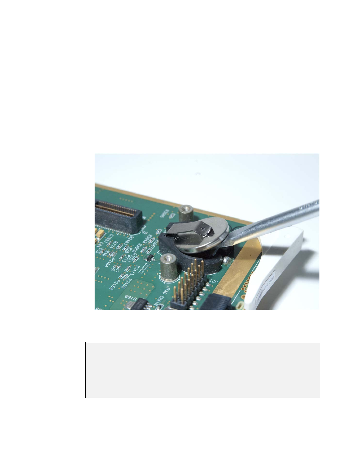
Your Miranda equipment comes with at least one lithium button battery (Li-MnO2) located on
the main printed circuit board. The batteries are used for backup and should not need to be
replaced during the lifetime of the equipment.
Before disposing of your Miranda equipment, please remove the battery as follows:
1 Make sure the equipment is unplugged from the power source.
2 Remove the protective cover from your equipment.
3 Gently remove the battery from its casing, using a blunt instrument such as a screwdriver for
leverage if necessary.
4 Dispose of the battery and equipment according to your local environmental laws and
guidelines.
WAR NIN G: Be careful not to short-circuit the batteries by adhering to the appropriate safe
handling practices. Do not dispose of batteries in a fire as they may explode.
Batteries may explode if damaged or overheated. Do not dispose of batteries
as household waste. Do not dismantle, open or shred batteries. Keep batteries
out of the reach of children. In the event of a bettery leak, do not allow battery
liquid to come into contact with skin or eyes. Seek medical help immediately
in case of ingestion, inhalation, skin or eye contact, or suspected exposure to
the contents of an opened battery.
For more information about recycling, please contact Miranda Technologies.
v
Page 6

General Warnings
A warning indicates a possible hazard to personnel which may cause injury or death. Observe
the following general warnings when using or working on this equipment:
• Heed all warnings on the unit and in the operating instructions.
• Do not use this equipment in or near water.
• This equipment is grounded through the grounding conductor of the power cord. To avoid
electrical shock, plug the power cord into a properly wired receptacle before connecting the
equipment inputs or outputs.
• Route power cords and other cables so they are not likely to be damaged.
• Disconnect power before cleaning the equipment. Do not use liquid or aerosol cleaners; use
only a damp cloth.
• Dangerous voltages may exist at several points in this equipment. To avoid injury, do not
touch exposed connections and components while power is on.
• Do not wear rings or wristwatches when troubleshooting high current circuits such as the
power supplies.
• To avoid fire hazard, use only the specified fuse(s) with the correct type number, voltage and
current ratings as referenced in the appropriate locations in the service instructions or on
the equipment. Always refer fuse replacements to qualified service personnel.
• There are no user-serviceable fuses in this equipment. Connection to the mains supply
should be via a circuit breaker or by a mains plug which meets the relevant local standards in
the country of installation.
• To avoid explosion, do not operate this equipment in an explosive atmosphere.
• Have qualified service personnel perform safety checks after any service.
• To avoid electrical shock or fire hazard, do not operate the equipment with its covers
removed.
• To prevent equipment from overheating, provide proper ventilation.
General Cautions
A caution indicates a possible hazard to equipment that could result in equipment damage.
Observe the following cautions when operating or working on this equipment:
• When installing this equipment, do not attach the power cord to building surfaces.
• To prevent damage to equipment when replacing fuses, locate and correct the problem that
caused the fuse to blow before re-applying power.
• Use only the specified replacement parts.
• Follow static precautions at all times when handling this equipment.
• This product should only be powered as described in the manual. To prevent equipment
damage, select the proper line voltage on the power supply(ies) as described in the installation documentation.
• To prevent damage to the equipment, read the instructions in the equipment manual for
proper input voltage range selection.
vi
Page 7

Symbols and Their Meanings
The lightning flash with arrowhead symbol within an equilateral triangle alerts the
user to the presence of dangerous voltages within the product’s enclosure that
may be of sufficient magnitude to constitute a risk of electric shock to persons.
The exclamation point within an equilateral triangle alerts the user to the presence
of important operating and maintenance/service instructions.
The ground symbol represents a protective grounding terminal. Such a terminal
must be connected to earth ground prior to making any other connections to the
equipment.
The fuse symbol indicates that the fuse referenced in the text must be replaced
with one having the ratings indicated.
The presence of this symbol in or on Miranda equipment means that it has been
designed, tested and certified as complying with applicable Underwriter’s Laboratory (USA) regulations and recommendations.
Imagestore 750
User Manual
The presence of this symbol in or on Miranda equipment means that it has been
designed, tested and certified as essentially complying with all applicable European Union (CE) regulations and recommendations.
When shipped into member countries of the European Community, this equipment
is accompanied by authentic copies of original Declarations of Conformance on file
in Miranda Technologies Inc. offices in Montreal, Canada.
vii
Page 8

viii
Page 9

Table of Contents
1 Preface . . . . . . . . . . . . . . . . . . . . . . . . . . . . . . . . . . . . . . . . . . . . . . . . 1
Chapter Structure . . . . . . . . . . . . . . . . . . . . . . . . . . . . . . . . . . . . . . . . . . . . . . . . . . . . . . . . . . . . . . . . . . . . . . . . . . . . . . 1
The PDF Document . . . . . . . . . . . . . . . . . . . . . . . . . . . . . . . . . . . . . . . . . . . . . . . . . . . . . . . . . . . . . . . . . . . . . . . . . . . . . 2
Terms, Conventions and Abbreviations . . . . . . . . . . . . . . . . . . . . . . . . . . . . . . . . . . . . . . . . . . . . . . . . . . . . . . . . . . 2
Scope of the Manual . . . . . . . . . . . . . . . . . . . . . . . . . . . . . . . . . . . . . . . . . . . . . . . . . . . . . . . . . . . . . . . . . . . . . . . . . . . . 3
Applicable Publications and Tools . . . . . . . . . . . . . . . . . . . . . . . . . . . . . . . . . . . . . . . . . . . . . . . . . . . . . . . . . . . . . . . 3
Publications. . . . . . . . . . . . . . . . . . . . . . . . . . . . . . . . . . . . . . . . . . . . . . . . . . . . . . . . . . . . . . . . . . . . . . . . . . . . . . . . 3
Software Tools . . . . . . . . . . . . . . . . . . . . . . . . . . . . . . . . . . . . . . . . . . . . . . . . . . . . . . . . . . . . . . . . . . . . . . . . . . . . . 4
2 Introduction . . . . . . . . . . . . . . . . . . . . . . . . . . . . . . . . . . . . . . . . . . . 5
Overview . . . . . . . . . . . . . . . . . . . . . . . . . . . . . . . . . . . . . . . . . . . . . . . . . . . . . . . . . . . . . . . . . . . . . . . . . . . . . . . . . . . . . . . 5
Functional Features . . . . . . . . . . . . . . . . . . . . . . . . . . . . . . . . . . . . . . . . . . . . . . . . . . . . . . . . . . . . . . . . . . . . . . . . . . . . 6
Multi-level Branding Graphics . . . . . . . . . . . . . . . . . . . . . . . . . . . . . . . . . . . . . . . . . . . . . . . . . . . . . . . . . . . . . . 6
Advanced Audio Mixing and Processing . . . . . . . . . . . . . . . . . . . . . . . . . . . . . . . . . . . . . . . . . . . . . . . . . . . . 7
Video Mixing. . . . . . . . . . . . . . . . . . . . . . . . . . . . . . . . . . . . . . . . . . . . . . . . . . . . . . . . . . . . . . . . . . . . . . . . . . . . . . . 7
Master Control . . . . . . . . . . . . . . . . . . . . . . . . . . . . . . . . . . . . . . . . . . . . . . . . . . . . . . . . . . . . . . . . . . . . . . . . . . . . . 8
Automated and Manual Control . . . . . . . . . . . . . . . . . . . . . . . . . . . . . . . . . . . . . . . . . . . . . . . . . . . . . . . . . . . . 8
Robust Design . . . . . . . . . . . . . . . . . . . . . . . . . . . . . . . . . . . . . . . . . . . . . . . . . . . . . . . . . . . . . . . . . . . . . . . . . . . . . 8
Architectural Summary . . . . . . . . . . . . . . . . . . . . . . . . . . . . . . . . . . . . . . . . . . . . . . . . . . . . . . . . . . . . . . . . . . . . . . . . . 9
Physical Features. . . . . . . . . . . . . . . . . . . . . . . . . . . . . . . . . . . . . . . . . . . . . . . . . . . . . . . . . . . . . . . . . . . . . . . . . . . . . . . 11
The Front Panel . . . . . . . . . . . . . . . . . . . . . . . . . . . . . . . . . . . . . . . . . . . . . . . . . . . . . . . . . . . . . . . . . . . . . . . . . . . 13
Symbols and Conventions . . . . . . . . . . . . . . . . . . . . . . . . . . . . . . . . . . . . . . . . . . . . . . . . . . . . . . . . . . . . 13
3 Applications . . . . . . . . . . . . . . . . . . . . . . . . . . . . . . . . . . . . . . . . . . 15
Three Scenarios . . . . . . . . . . . . . . . . . . . . . . . . . . . . . . . . . . . . . . . . . . . . . . . . . . . . . . . . . . . . . . . . . . . . . . . . . . . . . . . . 15
Downstream Branding . . . . . . . . . . . . . . . . . . . . . . . . . . . . . . . . . . . . . . . . . . . . . . . . . . . . . . . . . . . . . . . . . . . . 15
Master Control Switching . . . . . . . . . . . . . . . . . . . . . . . . . . . . . . . . . . . . . . . . . . . . . . . . . . . . . . . . . . . . . . . . . 16
Branding Insertion Options for Intuition XG . . . . . . . . . . . . . . . . . . . . . . . . . . . . . . . . . . . . . . . . . . . . . . . . 17
Fill/Key Branding Insertion . . . . . . . . . . . . . . . . . . . . . . . . . . . . . . . . . . . . . . . . . . . . . . . . . . . . . . . . . . . 17
Downstream Branding Insertion . . . . . . . . . . . . . . . . . . . . . . . . . . . . . . . . . . . . . . . . . . . . . . . . . . . . . . 17
In-Stream Branding Insertion . . . . . . . . . . . . . . . . . . . . . . . . . . . . . . . . . . . . . . . . . . . . . . . . . . . . . . . . . 18
Agile Audio Handling . . . . . . . . . . . . . . . . . . . . . . . . . . . . . . . . . . . . . . . . . . . . . . . . . . . . . . . . . . . . . . . . . . . . . . . . . . 19
Example 1. . . . . . . . . . . . . . . . . . . . . . . . . . . . . . . . . . . . . . . . . . . . . . . . . . . . . . . . . . . . . . . . . . . . . . . . . . . . . . . . . 19
Example 2. . . . . . . . . . . . . . . . . . . . . . . . . . . . . . . . . . . . . . . . . . . . . . . . . . . . . . . . . . . . . . . . . . . . . . . . . . . . . . . . . 20
4 Features . . . . . . . . . . . . . . . . . . . . . . . . . . . . . . . . . . . . . . . . . . . . . . 21
Video Standards . . . . . . . . . . . . . . . . . . . . . . . . . . . . . . . . . . . . . . . . . . . . . . . . . . . . . . . . . . . . . . . . . . . . . . . . . . . . . . . 21
Output . . . . . . . . . . . . . . . . . . . . . . . . . . . . . . . . . . . . . . . . . . . . . . . . . . . . . . . . . . . . . . . . . . . . . . . . . . . . . . . . . . . 21
Propagation Delay . . . . . . . . . . . . . . . . . . . . . . . . . . . . . . . . . . . . . . . . . . . . . . . . . . . . . . . . . . . . . . . . . . . . . . . . 22
Reference . . . . . . . . . . . . . . . . . . . . . . . . . . . . . . . . . . . . . . . . . . . . . . . . . . . . . . . . . . . . . . . . . . . . . . . . . . . . . . . . . . . . . 22
Reference Types . . . . . . . . . . . . . . . . . . . . . . . . . . . . . . . . . . . . . . . . . . . . . . . . . . . . . . . . . . . . . . . . . . . . . . . . . . 22
Adjusting Reference Timing . . . . . . . . . . . . . . . . . . . . . . . . . . . . . . . . . . . . . . . . . . . . . . . . . . . . . . . . . . . . . . . 23
HD Example (1080i) . . . . . . . . . . . . . . . . . . . . . . . . . . . . . . . . . . . . . . . . . . . . . . . . . . . . . . . . . . . . . . . . . . 24
Audio Processing . . . . . . . . . . . . . . . . . . . . . . . . . . . . . . . . . . . . . . . . . . . . . . . . . . . . . . . . . . . . . . . . . . . . . . . . . . . . . . 25
ix
Page 10

Table of Contents
Audio Graph . . . . . . . . . . . . . . . . . . . . . . . . . . . . . . . . . . . . . . . . . . . . . . . . . . . . . . . . . . . . . . . . . . . . . . . . . . . . . . 26
Sample Audio Graph Templates . . . . . . . . . . . . . . . . . . . . . . . . . . . . . . . . . . . . . . . . . . . . . . . . . . . . . . . . . . . 27
Embedded SDI Audio . . . . . . . . . . . . . . . . . . . . . . . . . . . . . . . . . . . . . . . . . . . . . . . . . . . . . . . . . . . . . . . . . . . . . 29
External AES Audio . . . . . . . . . . . . . . . . . . . . . . . . . . . . . . . . . . . . . . . . . . . . . . . . . . . . . . . . . . . . . . . . . . . . . . . 29
Audio A/B Mixing . . . . . . . . . . . . . . . . . . . . . . . . . . . . . . . . . . . . . . . . . . . . . . . . . . . . . . . . . . . . . . . . . . . . . . . . . 29
Voice-Overs . . . . . . . . . . . . . . . . . . . . . . . . . . . . . . . . . . . . . . . . . . . . . . . . . . . . . . . . . . . . . . . . . . . . . . . . . . . . . . 30
Easyplay . . . . . . . . . . . . . . . . . . . . . . . . . . . . . . . . . . . . . . . . . . . . . . . . . . . . . . . . . . . . . . . . . . . . . . . . . . . . . . . . . . 30
Switching Dolby E Signals . . . . . . . . . . . . . . . . . . . . . . . . . . . . . . . . . . . . . . . . . . . . . . . . . . . . . . . . . . . . . . . . . 31
Advanced Audio . . . . . . . . . . . . . . . . . . . . . . . . . . . . . . . . . . . . . . . . . . . . . . . . . . . . . . . . . . . . . . . . . . . . . . . . . . 31
Video A/B Mixing . . . . . . . . . . . . . . . . . . . . . . . . . . . . . . . . . . . . . . . . . . . . . . . . . . . . . . . . . . . . . . . . . . . . . . . . . . . . . . 31
Store Memory . . . . . . . . . . . . . . . . . . . . . . . . . . . . . . . . . . . . . . . . . . . . . . . . . . . . . . . . . . . . . . . . . . . . . . . . . . . . . . . . . 32
Keying Graphics . . . . . . . . . . . . . . . . . . . . . . . . . . . . . . . . . . . . . . . . . . . . . . . . . . . . . . . . . . . . . . . . . . . . . . . . . . . . . . . 32
External Graphics . . . . . . . . . . . . . . . . . . . . . . . . . . . . . . . . . . . . . . . . . . . . . . . . . . . . . . . . . . . . . . . . . . . . 32
Internal Media . . . . . . . . . . . . . . . . . . . . . . . . . . . . . . . . . . . . . . . . . . . . . . . . . . . . . . . . . . . . . . . . . . . . . . . 33
Emergency Alert System (EAS) . . . . . . . . . . . . . . . . . . . . . . . . . . . . . . . . . . . . . . . . . . . . . . . . . . . . . . . . 35
Temperature Probe . . . . . . . . . . . . . . . . . . . . . . . . . . . . . . . . . . . . . . . . . . . . . . . . . . . . . . . . . . . . . . . . . . 38
Keying Parameters . . . . . . . . . . . . . . . . . . . . . . . . . . . . . . . . . . . . . . . . . . . . . . . . . . . . . . . . . . . . . . . . . . . 39
DVE (for Program and Preview) . . . . . . . . . . . . . . . . . . . . . . . . . . . . . . . . . . . . . . . . . . . . . . . . . . . . . . . . . . . . . . . . 41
Video Frame Delays . . . . . . . . . . . . . . . . . . . . . . . . . . . . . . . . . . . . . . . . . . . . . . . . . . . . . . . . . . . . . . . . . . . . . . . . . . . 43
Preview Output . . . . . . . . . . . . . . . . . . . . . . . . . . . . . . . . . . . . . . . . . . . . . . . . . . . . . . . . . . . . . . . . . . . . . . . . . . . . . . . 43
Active Preview AB Mixer . . . . . . . . . . . . . . . . . . . . . . . . . . . . . . . . . . . . . . . . . . . . . . . . . . . . . . . . . . . . . . . . . . 44
Active Preview Keyers . . . . . . . . . . . . . . . . . . . . . . . . . . . . . . . . . . . . . . . . . . . . . . . . . . . . . . . . . . . . . . . . . . . . . 44
Clean-Feed Output . . . . . . . . . . . . . . . . . . . . . . . . . . . . . . . . . . . . . . . . . . . . . . . . . . . . . . . . . . . . . . . . . . . . . . . . . . . . 45
Monitor Output . . . . . . . . . . . . . . . . . . . . . . . . . . . . . . . . . . . . . . . . . . . . . . . . . . . . . . . . . . . . . . . . . . . . . . . . . . . . . . . 46
General Purpose Interface (GPI) . . . . . . . . . . . . . . . . . . . . . . . . . . . . . . . . . . . . . . . . . . . . . . . . . . . . . . . . . . . . . . . . 47
GPI Inputs and Macros . . . . . . . . . . . . . . . . . . . . . . . . . . . . . . . . . . . . . . . . . . . . . . . . . . . . . . . . . . . . . . . 48
GPI Outputs and Events . . . . . . . . . . . . . . . . . . . . . . . . . . . . . . . . . . . . . . . . . . . . . . . . . . . . . . . . . . . . . . 50
Macros . . . . . . . . . . . . . . . . . . . . . . . . . . . . . . . . . . . . . . . . . . . . . . . . . . . . . . . . . . . . . . . . . . . . . . . . . . . . . . . . . . . . . . . . 50
Adding Macros . . . . . . . . . . . . . . . . . . . . . . . . . . . . . . . . . . . . . . . . . . . . . . . . . . . . . . . . . . . . . . . . . . . . . . 51
Triggering Macros . . . . . . . . . . . . . . . . . . . . . . . . . . . . . . . . . . . . . . . . . . . . . . . . . . . . . . . . . . . . . . . . . . . 52
Graphics Co-Processors . . . . . . . . . . . . . . . . . . . . . . . . . . . . . . . . . . . . . . . . . . . . . . . . . . . . . . . . . . . . . . . . . . . . . . . . 52
Oxtel Command Forwarding to a Co-Processor . . . . . . . . . . . . . . . . . . . . . . . . . . . . . . . . . . . . . . . 53
Automatic Keyer Management . . . . . . . . . . . . . . . . . . . . . . . . . . . . . . . . . . . . . . . . . . . . . . . . . . . . . . . 54
Closed Captions . . . . . . . . . . . . . . . . . . . . . . . . . . . . . . . . . . . . . . . . . . . . . . . . . . . . . . . . . . . . . . . . . . . . . . . . . . . . . . . 56
Timecode . . . . . . . . . . . . . . . . . . . . . . . . . . . . . . . . . . . . . . . . . . . . . . . . . . . . . . . . . . . . . . . . . . . . . . . . . . . . . . . . . . . . . 56
Message Logging . . . . . . . . . . . . . . . . . . . . . . . . . . . . . . . . . . . . . . . . . . . . . . . . . . . . . . . . . . . . . . . . . . . . . . . . . . . . . . 57
Logging Level . . . . . . . . . . . . . . . . . . . . . . . . . . . . . . . . . . . . . . . . . . . . . . . . . . . . . . . . . . . . . . . . . . . . . . . 57
External Logging . . . . . . . . . . . . . . . . . . . . . . . . . . . . . . . . . . . . . . . . . . . . . . . . . . . . . . . . . . . . . . . . . . . . . 57
Local Logging . . . . . . . . . . . . . . . . . . . . . . . . . . . . . . . . . . . . . . . . . . . . . . . . . . . . . . . . . . . . . . . . . . . . . . . 58
System Configuration . . . . . . . . . . . . . . . . . . . . . . . . . . . . . . . . . . . . . . . . . . . . . . . . . . . . . . . . . . . . . . . . . . . . . . . . . . 58
Video Bypass . . . . . . . . . . . . . . . . . . . . . . . . . . . . . . . . . . . . . . . . . . . . . . . . . . . . . . . . . . . . . . . . . . . . . . . . . . . . . . . . . . 58
5 Master Control . . . . . . . . . . . . . . . . . . . . . . . . . . . . . . . . . . . . . . . . 59
Overview . . . . . . . . . . . . . . . . . . . . . . . . . . . . . . . . . . . . . . . . . . . . . . . . . . . . . . . . . . . . . . . . . . . . . . . . . . . . . . . . . . . . . . 59
Devices . . . . . . . . . . . . . . . . . . . . . . . . . . . . . . . . . . . . . . . . . . . . . . . . . . . . . . . . . . . . . . . . . . . . . . . . . . . . . . . . . . . 61
Features . . . . . . . . . . . . . . . . . . . . . . . . . . . . . . . . . . . . . . . . . . . . . . . . . . . . . . . . . . . . . . . . . . . . . . . . . . . . . . . . . . 61
Imagestore 750 Configuration Overview . . . . . . . . . . . . . . . . . . . . . . . . . . . . . . . . . . . . . . . . . . . . . . . . . . . 62
NV9000’s IP Address . . . . . . . . . . . . . . . . . . . . . . . . . . . . . . . . . . . . . . . . . . . . . . . . . . . . . . . . . . . . . . . . . 63
Channel Sources . . . . . . . . . . . . . . . . . . . . . . . . . . . . . . . . . . . . . . . . . . . . . . . . . . . . . . . . . . . . . . . . . . . . . 63
Source Groups . . . . . . . . . . . . . . . . . . . . . . . . . . . . . . . . . . . . . . . . . . . . . . . . . . . . . . . . . . . . . . . . . . . . . . . 64
Router Salvos . . . . . . . . . . . . . . . . . . . . . . . . . . . . . . . . . . . . . . . . . . . . . . . . . . . . . . . . . . . . . . . . . . . . . . . . 64
Router Destinations (Feeding Program and Preset Inputs) . . . . . . . . . . . . . . . . . . . . . . . . . . . . . 64
Router Destination (Feeding AUX) . . . . . . . . . . . . . . . . . . . . . . . . . . . . . . . . . . . . . . . . . . . . . . . . . . . . 65
Router Sources (Fed by PGM, PST, CLN, and MON Outputs) . . . . . . . . . . . . . . . . . . . . . . . . . . . . 65
Router Source (Fed by BLACK/SILENCE) . . . . . . . . . . . . . . . . . . . . . . . . . . . . . . . . . . . . . . . . . . . . . . . 65
x
Page 11

Router Source (Fed by USER 1-20) . . . . . . . . . . . . . . . . . . . . . . . . . . . . . . . . . . . . . . . . . . . . . . . . . . . . 65
Graphics Co-Processor Feeding Fill and Key . . . . . . . . . . . . . . . . . . . . . . . . . . . . . . . . . . . . . . . . . . . 65
Channel Acquisition and Ownership . . . . . . . . . . . . . . . . . . . . . . . . . . . . . . . . . . . . . . . . . . . . . . . . . . 66
Monitor Wall . . . . . . . . . . . . . . . . . . . . . . . . . . . . . . . . . . . . . . . . . . . . . . . . . . . . . . . . . . . . . . . . . . . . . . . . . 66
Hardware Connections . . . . . . . . . . . . . . . . . . . . . . . . . . . . . . . . . . . . . . . . . . . . . . . . . . . . . . . . . . . . . . . . . . . . . . . . 67
Cable Connections . . . . . . . . . . . . . . . . . . . . . . . . . . . . . . . . . . . . . . . . . . . . . . . . . . . . . . . . . . . . . . . . . . . . . . . . 67
Video Connections . . . . . . . . . . . . . . . . . . . . . . . . . . . . . . . . . . . . . . . . . . . . . . . . . . . . . . . . . . . . . . . . . . . . . . . . 68
Network Connections . . . . . . . . . . . . . . . . . . . . . . . . . . . . . . . . . . . . . . . . . . . . . . . . . . . . . . . . . . . . . . . . . . . . . 68
NV9000 . . . . . . . . . . . . . . . . . . . . . . . . . . . . . . . . . . . . . . . . . . . . . . . . . . . . . . . . . . . . . . . . . . . . . . . . . . . . . . 69
Imagestore 750. . . . . . . . . . . . . . . . . . . . . . . . . . . . . . . . . . . . . . . . . . . . . . . . . . . . . . . . . . . . . . . . . . . . . . . 69
Intuition XG . . . . . . . . . . . . . . . . . . . . . . . . . . . . . . . . . . . . . . . . . . . . . . . . . . . . . . . . . . . . . . . . . . . . . . . . . . 69
iMC Panels . . . . . . . . . . . . . . . . . . . . . . . . . . . . . . . . . . . . . . . . . . . . . . . . . . . . . . . . . . . . . . . . . . . . . . . . . . . 69
Configuration PC . . . . . . . . . . . . . . . . . . . . . . . . . . . . . . . . . . . . . . . . . . . . . . . . . . . . . . . . . . . . . . . . . . . . . 69
Serial Connections . . . . . . . . . . . . . . . . . . . . . . . . . . . . . . . . . . . . . . . . . . . . . . . . . . . . . . . . . . . . . . . . . . . . . . . . 70
Serial Connection to Automation . . . . . . . . . . . . . . . . . . . . . . . . . . . . . . . . . . . . . . . . . . . . . . . . . . . . . 70
Serial Connection to Intuition XG . . . . . . . . . . . . . . . . . . . . . . . . . . . . . . . . . . . . . . . . . . . . . . . . . . . . . 70
Software Configuration . . . . . . . . . . . . . . . . . . . . . . . . . . . . . . . . . . . . . . . . . . . . . . . . . . . . . . . . . . . . . . . . . . . . . . . . 70
Software Versions . . . . . . . . . . . . . . . . . . . . . . . . . . . . . . . . . . . . . . . . . . . . . . . . . . . . . . . . . . . . . . . . . . . . . . . . . 71
Router Connections . . . . . . . . . . . . . . . . . . . . . . . . . . . . . . . . . . . . . . . . . . . . . . . . . . . . . . . . . . . . . . . . . . . . . . . 71
Master Control Configuration . . . . . . . . . . . . . . . . . . . . . . . . . . . . . . . . . . . . . . . . . . . . . . . . . . . . . . . . . . . . . 72
Channel Sources Configuration . . . . . . . . . . . . . . . . . . . . . . . . . . . . . . . . . . . . . . . . . . . . . . . . . . . . . . . 73
Channel Source Templates . . . . . . . . . . . . . . . . . . . . . . . . . . . . . . . . . . . . . . . . . . . . . . . . . . . . . . . . . . . 74
Source Groups Configuration . . . . . . . . . . . . . . . . . . . . . . . . . . . . . . . . . . . . . . . . . . . . . . . . . . . . . . . . . 77
Master Control Configuration Cross-Reference . . . . . . . . . . . . . . . . . . . . . . . . . . . . . . . . . . . . . . . . 80
Salvo Configuration . . . . . . . . . . . . . . . . . . . . . . . . . . . . . . . . . . . . . . . . . . . . . . . . . . . . . . . . . . . . . . . . . . . . . . . 80
Salvo Configuration Cross-Reference . . . . . . . . . . . . . . . . . . . . . . . . . . . . . . . . . . . . . . . . . . . . . . . . . 83
Router Destinations . . . . . . . . . . . . . . . . . . . . . . . . . . . . . . . . . . . . . . . . . . . . . . . . . . . . . . . . . . . . . . . . . . . . . . . 83
Router Sources . . . . . . . . . . . . . . . . . . . . . . . . . . . . . . . . . . . . . . . . . . . . . . . . . . . . . . . . . . . . . . . . . . . . . . . . . . . 85
Graphics Co-Processor Configuration . . . . . . . . . . . . . . . . . . . . . . . . . . . . . . . . . . . . . . . . . . . . . . . . . . . . . . 86
Slave Settings . . . . . . . . . . . . . . . . . . . . . . . . . . . . . . . . . . . . . . . . . . . . . . . . . . . . . . . . . . . . . . . . . . . . . . . . 86
External Fill/Key Settings. . . . . . . . . . . . . . . . . . . . . . . . . . . . . . . . . . . . . . . . . . . . . . . . . . . . . . . . . . . . . . 88
Channel Acquisition and Ownership Configuration . . . . . . . . . . . . . . . . . . . . . . . . . . . . . . . . . . . . . . . . 89
Channel Selection Configuration . . . . . . . . . . . . . . . . . . . . . . . . . . . . . . . . . . . . . . . . . . . . . . . . . . . . . 90
Panel Permissions Configuration . . . . . . . . . . . . . . . . . . . . . . . . . . . . . . . . . . . . . . . . . . . . . . . . . . . . . 91
Channel Permissions Configuration . . . . . . . . . . . . . . . . . . . . . . . . . . . . . . . . . . . . . . . . . . . . . . . . . . . 92
Monitor Wall Configuration . . . . . . . . . . . . . . . . . . . . . . . . . . . . . . . . . . . . . . . . . . . . . . . . . . . . . . . . . . . . . . . 93
Monitor Wall Source Group Configuration . . . . . . . . . . . . . . . . . . . . . . . . . . . . . . . . . . . . . . . . . . . . 94
Monitor Wall Configuration . . . . . . . . . . . . . . . . . . . . . . . . . . . . . . . . . . . . . . . . . . . . . . . . . . . . . . . . . . 95
Channel Acquisition Salvos . . . . . . . . . . . . . . . . . . . . . . . . . . . . . . . . . . . . . . . . . . . . . . . . . . . . . . . . . . . 96
Miscellaneous Router Configuration . . . . . . . . . . . . . . . . . . . . . . . . . . . . . . . . . . . . . . . . . . . . . . . . . . . . . . . 97
Channel Transitions . . . . . . . . . . . . . . . . . . . . . . . . . . . . . . . . . . . . . . . . . . . . . . . . . . . . . . . . . . . . . . . . . . . . . . . 98
Transition Parameters . . . . . . . . . . . . . . . . . . . . . . . . . . . . . . . . . . . . . . . . . . . . . . . . . . . . . . . . . . . . . . . . 98
Transition Rates . . . . . . . . . . . . . . . . . . . . . . . . . . . . . . . . . . . . . . . . . . . . . . . . . . . . . . . . . . . . . . . . . . . . . . 99
Transition Type Profiles . . . . . . . . . . . . . . . . . . . . . . . . . . . . . . . . . . . . . . . . . . . . . . . . . . . . . . . . . . . . . . 100
Transition Rate for DSKs . . . . . . . . . . . . . . . . . . . . . . . . . . . . . . . . . . . . . . . . . . . . . . . . . . . . . . . . . . . . . 101
Transition Rate for Voice-Overs . . . . . . . . . . . . . . . . . . . . . . . . . . . . . . . . . . . . . . . . . . . . . . . . . . . . . . 102
Panel Behavior Configuration . . . . . . . . . . . . . . . . . . . . . . . . . . . . . . . . . . . . . . . . . . . . . . . . . . . . . . . . . . . . 102
Imagestore 750
User Manual
6 Advanced Audio . . . . . . . . . . . . . . . . . . . . . . . . . . . . . . . . . . . . . 105
Dolby . . . . . . . . . . . . . . . . . . . . . . . . . . . . . . . . . . . . . . . . . . . . . . . . . . . . . . . . . . . . . . . . . . . . . . . . . . . . . . . . . . . . . . . . 105
Introduction . . . . . . . . . . . . . . . . . . . . . . . . . . . . . . . . . . . . . . . . . . . . . . . . . . . . . . . . . . . . . . . . . . . . . . . . . . . . . 105
Dolby Data Types . . . . . . . . . . . . . . . . . . . . . . . . . . . . . . . . . . . . . . . . . . . . . . . . . . . . . . . . . . . . . . . . . . . . . . . . 106
Dolby Digital (AC-3) . . . . . . . . . . . . . . . . . . . . . . . . . . . . . . . . . . . . . . . . . . . . . . . . . . . . . . . . . . . . . . . . . 106
Dolby E . . . . . . . . . . . . . . . . . . . . . . . . . . . . . . . . . . . . . . . . . . . . . . . . . . . . . . . . . . . . . . . . . . . . . . . . . . . . . 106
Dolby Metadata . . . . . . . . . . . . . . . . . . . . . . . . . . . . . . . . . . . . . . . . . . . . . . . . . . . . . . . . . . . . . . . . . . . . . 106
xi
Page 12

Table of Contents
Dolby Handling on Legacy Systems . . . . . . . . . . . . . . . . . . . . . . . . . . . . . . . . . . . . . . . . . . . . . . . . . . . . . . 106
Installing Dolby Options . . . . . . . . . . . . . . . . . . . . . . . . . . . . . . . . . . . . . . . . . . . . . . . . . . . . . . . . . . . . . . . . . 107
Dolby Overview . . . . . . . . . . . . . . . . . . . . . . . . . . . . . . . . . . . . . . . . . . . . . . . . . . . . . . . . . . . . . . . . . . . . . . . . . 108
Decode and Encode Combinations . . . . . . . . . . . . . . . . . . . . . . . . . . . . . . . . . . . . . . . . . . . . . . . . . . . . . . . 109
Product Codes . . . . . . . . . . . . . . . . . . . . . . . . . . . . . . . . . . . . . . . . . . . . . . . . . . . . . . . . . . . . . . . . . . . . . . . . . . . 111
Technical Specifications . . . . . . . . . . . . . . . . . . . . . . . . . . . . . . . . . . . . . . . . . . . . . . . . . . . . . . . . . . . . . . . . . . 113
Dolby Decode Module . . . . . . . . . . . . . . . . . . . . . . . . . . . . . . . . . . . . . . . . . . . . . . . . . . . . . . . . . . . . . . 113
Dolby E Encoder Module . . . . . . . . . . . . . . . . . . . . . . . . . . . . . . . . . . . . . . . . . . . . . . . . . . . . . . . . . . . . 115
Dolby Digital Encoder Module . . . . . . . . . . . . . . . . . . . . . . . . . . . . . . . . . . . . . . . . . . . . . . . . . . . . . . . 116
Dolby Processing Times . . . . . . . . . . . . . . . . . . . . . . . . . . . . . . . . . . . . . . . . . . . . . . . . . . . . . . . . . . . . . 117
Upgrading Dolby Module Firmware . . . . . . . . . . . . . . . . . . . . . . . . . . . . . . . . . . . . . . . . . . . . . . . . . 118
Dolby Front Panel Display Items . . . . . . . . . . . . . . . . . . . . . . . . . . . . . . . . . . . . . . . . . . . . . . . . . . . . . 118
Configuring Dolby . . . . . . . . . . . . . . . . . . . . . . . . . . . . . . . . . . . . . . . . . . . . . . . . . . . . . . . . . . . . . . . . . . . . . . . 118
Automation Control . . . . . . . . . . . . . . . . . . . . . . . . . . . . . . . . . . . . . . . . . . . . . . . . . . . . . . . . . . . . . . . . . . . . . 119
Dolby Decoder Modules . . . . . . . . . . . . . . . . . . . . . . . . . . . . . . . . . . . . . . . . . . . . . . . . . . . . . . . . . . . . 119
Dolby E Encoder Modules . . . . . . . . . . . . . . . . . . . . . . . . . . . . . . . . . . . . . . . . . . . . . . . . . . . . . . . . . . . 119
Dolby Digital Encoder Modules . . . . . . . . . . . . . . . . . . . . . . . . . . . . . . . . . . . . . . . . . . . . . . . . . . . . . . 119
Dolby Metadata . . . . . . . . . . . . . . . . . . . . . . . . . . . . . . . . . . . . . . . . . . . . . . . . . . . . . . . . . . . . . . . . . . . . . . . . . 120
Program Configuration . . . . . . . . . . . . . . . . . . . . . . . . . . . . . . . . . . . . . . . . . . . . . . . . . . . . . . . . . . . . . . 120
Metadata Sources . . . . . . . . . . . . . . . . . . . . . . . . . . . . . . . . . . . . . . . . . . . . . . . . . . . . . . . . . . . . . . . . . . . 122
Metadata Destinations . . . . . . . . . . . . . . . . . . . . . . . . . . . . . . . . . . . . . . . . . . . . . . . . . . . . . . . . . . . . . . 122
Metadata Routing . . . . . . . . . . . . . . . . . . . . . . . . . . . . . . . . . . . . . . . . . . . . . . . . . . . . . . . . . . . . . . . . . . . 122
Custom-Defined Metadata Presets . . . . . . . . . . . . . . . . . . . . . . . . . . . . . . . . . . . . . . . . . . . . . . . . . . . 125
Metadata Mode . . . . . . . . . . . . . . . . . . . . . . . . . . . . . . . . . . . . . . . . . . . . . . . . . . . . . . . . . . . . . . . . . . . . 126
‘Modes & Levels’ Tab . . . . . . . . . . . . . . . . . . . . . . . . . . . . . . . . . . . . . . . . . . . . . . . . . . . . . . . . . . . . . . . . 127
Features Tab . . . . . . . . . . . . . . . . . . . . . . . . . . . . . . . . . . . . . . . . . . . . . . . . . . . . . . . . . . . . . . . . . . . . . . . . 131
Compression Tab . . . . . . . . . . . . . . . . . . . . . . . . . . . . . . . . . . . . . . . . . . . . . . . . . . . . . . . . . . . . . . . . . . . 132
Dynamic Range Tab . . . . . . . . . . . . . . . . . . . . . . . . . . . . . . . . . . . . . . . . . . . . . . . . . . . . . . . . . . . . . . . . . 132
Automation Control . . . . . . . . . . . . . . . . . . . . . . . . . . . . . . . . . . . . . . . . . . . . . . . . . . . . . . . . . . . . . . . . . 133
Up-Mix . . . . . . . . . . . . . . . . . . . . . . . . . . . . . . . . . . . . . . . . . . . . . . . . . . . . . . . . . . . . . . . . . . . . . . . . . . . . . . . . . . . . . . . 133
Up-Mix Configurations . . . . . . . . . . . . . . . . . . . . . . . . . . . . . . . . . . . . . . . . . . . . . . . . . . . . . . . . . . . . . . . . . . . 134
Product Codes . . . . . . . . . . . . . . . . . . . . . . . . . . . . . . . . . . . . . . . . . . . . . . . . . . . . . . . . . . . . . . . . . . . . . . . . . . . 134
Up-Mix Kit . . . . . . . . . . . . . . . . . . . . . . . . . . . . . . . . . . . . . . . . . . . . . . . . . . . . . . . . . . . . . . . . . . . . . . . . . . 134
Up-Mix Upgrade . . . . . . . . . . . . . . . . . . . . . . . . . . . . . . . . . . . . . . . . . . . . . . . . . . . . . . . . . . . . . . . . . . . . 134
Technical Specifications . . . . . . . . . . . . . . . . . . . . . . . . . . . . . . . . . . . . . . . . . . . . . . . . . . . . . . . . . . . . . . . . . . 135
Up-Mix Module . . . . . . . . . . . . . . . . . . . . . . . . . . . . . . . . . . . . . . . . . . . . . . . . . . . . . . . . . . . . . . . . . . . . . 135
Up-Mix Processing Times . . . . . . . . . . . . . . . . . . . . . . . . . . . . . . . . . . . . . . . . . . . . . . . . . . . . . . . . . . . . 136
Upgrading Up-Mix Module Firmware . . . . . . . . . . . . . . . . . . . . . . . . . . . . . . . . . . . . . . . . . . . . . . . . 137
Configuring Up-Mix . . . . . . . . . . . . . . . . . . . . . . . . . . . . . . . . . . . . . . . . . . . . . . . . . . . . . . . . . . . . . . . . . . . . . . 137
Imagestore 750 Configurator . . . . . . . . . . . . . . . . . . . . . . . . . . . . . . . . . . . . . . . . . . . . . . . . . . . . . . . . 137
Connecting Up-Mix Modules . . . . . . . . . . . . . . . . . . . . . . . . . . . . . . . . . . . . . . . . . . . . . . . . . . . . . . . . 138
Connecting Metadata to Up-Mix Modules . . . . . . . . . . . . . . . . . . . . . . . . . . . . . . . . . . . . . . . . . . . 138
Metadata . . . . . . . . . . . . . . . . . . . . . . . . . . . . . . . . . . . . . . . . . . . . . . . . . . . . . . . . . . . . . . . . . . . . . . . . . . . 139
Metadata Monitoring and Processing . . . . . . . . . . . . . . . . . . . . . . . . . . . . . . . . . . . . . . . . . . . . . . . . 140
Custom-Defined Metadata Presets . . . . . . . . . . . . . . . . . . . . . . . . . . . . . . . . . . . . . . . . . . . . . . . . . . . 140
Automation Control . . . . . . . . . . . . . . . . . . . . . . . . . . . . . . . . . . . . . . . . . . . . . . . . . . . . . . . . . . . . . . . . . . . . . 140
Up-Mix Modules . . . . . . . . . . . . . . . . . . . . . . . . . . . . . . . . . . . . . . . . . . . . . . . . . . . . . . . . . . . . . . . . . . . . 140
Audio Description (AD) . . . . . . . . . . . . . . . . . . . . . . . . . . . . . . . . . . . . . . . . . . . . . . . . . . . . . . . . . . . . . . . . . . . . . . . 140
AD Receiver Mix . . . . . . . . . . . . . . . . . . . . . . . . . . . . . . . . . . . . . . . . . . . . . . . . . . . . . . . . . . . . . . . . . . . . . . . . . 141
AD Broadcast Mix . . . . . . . . . . . . . . . . . . . . . . . . . . . . . . . . . . . . . . . . . . . . . . . . . . . . . . . . . . . . . . . . . . . . . . . . 141
Product Code . . . . . . . . . . . . . . . . . . . . . . . . . . . . . . . . . . . . . . . . . . . . . . . . . . . . . . . . . . . . . . . . . . . . . . . . . . . . 141
Configuration . . . . . . . . . . . . . . . . . . . . . . . . . . . . . . . . . . . . . . . . . . . . . . . . . . . . . . . . . . . . . . . . . . . . . . . . . . . 141
Silence Detection . . . . . . . . . . . . . . . . . . . . . . . . . . . . . . . . . . . . . . . . . . . . . . . . . . . . . . . . . . . . . . . . . . . . . . . . . . . . . 143
Introduction . . . . . . . . . . . . . . . . . . . . . . . . . . . . . . . . . . . . . . . . . . . . . . . . . . . . . . . . . . . . . . . . . . . . . . . . . . . . . 143
Configuration . . . . . . . . . . . . . . . . . . . . . . . . . . . . . . . . . . . . . . . . . . . . . . . . . . . . . . . . . . . . . . . . . . . . . . . . . . . 143
Audio Delays . . . . . . . . . . . . . . . . . . . . . . . . . . . . . . . . . . . . . . . . . . . . . . . . . . . . . . . . . . . . . . . . . . . . . . . . . . . . . . . . . 146
xii
Page 13

Dolby Delays . . . . . . . . . . . . . . . . . . . . . . . . . . . . . . . . . . . . . . . . . . . . . . . . . . . . . . . . . . . . . . . . . . . . . . . . . . . . 146
Metadata Delays . . . . . . . . . . . . . . . . . . . . . . . . . . . . . . . . . . . . . . . . . . . . . . . . . . . . . . . . . . . . . . . . . . . . . . . . . 148
Audio Delay Blocks . . . . . . . . . . . . . . . . . . . . . . . . . . . . . . . . . . . . . . . . . . . . . . . . . . . . . . . . . . . . . . . . . . . . . . 148
7 Control and Monitoring . . . . . . . . . . . . . . . . . . . . . . . . . . . . . . 149
Control Options . . . . . . . . . . . . . . . . . . . . . . . . . . . . . . . . . . . . . . . . . . . . . . . . . . . . . . . . . . . . . . . . . . . . . . . . . . . . . . 149
Front Panel . . . . . . . . . . . . . . . . . . . . . . . . . . . . . . . . . . . . . . . . . . . . . . . . . . . . . . . . . . . . . . . . . . . . . . . . . . . . . . 149
Automation . . . . . . . . . . . . . . . . . . . . . . . . . . . . . . . . . . . . . . . . . . . . . . . . . . . . . . . . . . . . . . . . . . . . . . . . . . . . . 150
iMC Panels . . . . . . . . . . . . . . . . . . . . . . . . . . . . . . . . . . . . . . . . . . . . . . . . . . . . . . . . . . . . . . . . . . . . . . . . . . . . . . 150
PresStation / Presmaster . . . . . . . . . . . . . . . . . . . . . . . . . . . . . . . . . . . . . . . . . . . . . . . . . . . . . . . . . . . . . . . . . 150
GPI Controller Switch . . . . . . . . . . . . . . . . . . . . . . . . . . . . . . . . . . . . . . . . . . . . . . . . . . . . . . . . . . . . . . . . . . . . 150
Emergency Alert System . . . . . . . . . . . . . . . . . . . . . . . . . . . . . . . . . . . . . . . . . . . . . . . . . . . . . . . . . . . . . . . . . 151
Monitoring and Alarms . . . . . . . . . . . . . . . . . . . . . . . . . . . . . . . . . . . . . . . . . . . . . . . . . . . . . . . . . . . . . . . . . . . . . . . 151
Alarm Levels . . . . . . . . . . . . . . . . . . . . . . . . . . . . . . . . . . . . . . . . . . . . . . . . . . . . . . . . . . . . . . . . . . . . . . . . . . . . . 151
SNMP Traps . . . . . . . . . . . . . . . . . . . . . . . . . . . . . . . . . . . . . . . . . . . . . . . . . . . . . . . . . . . . . . . . . . . . . . . . . . . . . 153
Status LED . . . . . . . . . . . . . . . . . . . . . . . . . . . . . . . . . . . . . . . . . . . . . . . . . . . . . . . . . . . . . . . . . . . . . . . . . . . . . . . 154
8 Imagestore 750 Configurator. . . . . . . . . . . . . . . . . . . . . . . . . . 155
Introduction . . . . . . . . . . . . . . . . . . . . . . . . . . . . . . . . . . . . . . . . . . . . . . . . . . . . . . . . . . . . . . . . . . . . . . . . . . . . . . . . . . 155
Configurator Mode Selection . . . . . . . . . . . . . . . . . . . . . . . . . . . . . . . . . . . . . . . . . . . . . . . . . . . . . . . . . . . . . 155
Modes . . . . . . . . . . . . . . . . . . . . . . . . . . . . . . . . . . . . . . . . . . . . . . . . . . . . . . . . . . . . . . . . . . . . . . . . . . . . . . . . . . . . . . . . 156
Configuration Mode . . . . . . . . . . . . . . . . . . . . . . . . . . . . . . . . . . . . . . . . . . . . . . . . . . . . . . . . . . . . . . . . . . . . . 156
System Settings . . . . . . . . . . . . . . . . . . . . . . . . . . . . . . . . . . . . . . . . . . . . . . . . . . . . . . . . . . . . . . . . . . . . . 158
Store Manager . . . . . . . . . . . . . . . . . . . . . . . . . . . . . . . . . . . . . . . . . . . . . . . . . . . . . . . . . . . . . . . . . . . . . . 161
Audio Graph . . . . . . . . . . . . . . . . . . . . . . . . . . . . . . . . . . . . . . . . . . . . . . . . . . . . . . . . . . . . . . . . . . . . . . . . 161
Licences . . . . . . . . . . . . . . . . . . . . . . . . . . . . . . . . . . . . . . . . . . . . . . . . . . . . . . . . . . . . . . . . . . . . . . . . . . . . 169
Metadata Mode . . . . . . . . . . . . . . . . . . . . . . . . . . . . . . . . . . . . . . . . . . . . . . . . . . . . . . . . . . . . . . . . . . . . . . . . . . 169
Gain Mode . . . . . . . . . . . . . . . . . . . . . . . . . . . . . . . . . . . . . . . . . . . . . . . . . . . . . . . . . . . . . . . . . . . . . . . . . . . . . . 170
Shuffle Mode . . . . . . . . . . . . . . . . . . . . . . . . . . . . . . . . . . . . . . . . . . . . . . . . . . . . . . . . . . . . . . . . . . . . . . . . . . . . 171
Master Control Mode . . . . . . . . . . . . . . . . . . . . . . . . . . . . . . . . . . . . . . . . . . . . . . . . . . . . . . . . . . . . . . . . . . . . 172
Salvo Mode . . . . . . . . . . . . . . . . . . . . . . . . . . . . . . . . . . . . . . . . . . . . . . . . . . . . . . . . . . . . . . . . . . . . . . . . . . . . . . 172
Macro Mode . . . . . . . . . . . . . . . . . . . . . . . . . . . . . . . . . . . . . . . . . . . . . . . . . . . . . . . . . . . . . . . . . . . . . . . . . . . . . 173
DVE Mode . . . . . . . . . . . . . . . . . . . . . . . . . . . . . . . . . . . . . . . . . . . . . . . . . . . . . . . . . . . . . . . . . . . . . . . . . . . . . . . 174
Managing Configurations . . . . . . . . . . . . . . . . . . . . . . . . . . . . . . . . . . . . . . . . . . . . . . . . . . . . . . . . . . . . . . . . . . . . . 175
Saving a Configuration . . . . . . . . . . . . . . . . . . . . . . . . . . . . . . . . . . . . . . . . . . . . . . . . . . . . . . . . . . . . . . . . . . . 175
Importing a Configuration. . . . . . . . . . . . . . . . . . . . . . . . . . . . . . . . . . . . . . . . . . . . . . . . . . . . . . . . . . . . . . . . 175
Exporting a Capabilities File . . . . . . . . . . . . . . . . . . . . . . . . . . . . . . . . . . . . . . . . . . . . . . . . . . . . . . . . . . . . . . 176
Imagestore 750
User Manual
9 Web Interface . . . . . . . . . . . . . . . . . . . . . . . . . . . . . . . . . . . . . . . . 177
Connecting . . . . . . . . . . . . . . . . . . . . . . . . . . . . . . . . . . . . . . . . . . . . . . . . . . . . . . . . . . . . . . . . . . . . . . . . . . . . . . . . . . 177
Web Interface Pages . . . . . . . . . . . . . . . . . . . . . . . . . . . . . . . . . . . . . . . . . . . . . . . . . . . . . . . . . . . . . . . . . . . . . . . . . . 178
Front Panel Mirror . . . . . . . . . . . . . . . . . . . . . . . . . . . . . . . . . . . . . . . . . . . . . . . . . . . . . . . . . . . . . . . . . . . . . . . 178
System Information . . . . . . . . . . . . . . . . . . . . . . . . . . . . . . . . . . . . . . . . . . . . . . . . . . . . . . . . . . . . . . . . . . . . . . 179
Media Management . . . . . . . . . . . . . . . . . . . . . . . . . . . . . . . . . . . . . . . . . . . . . . . . . . . . . . . . . . . . . . . . . . . . . 180
Audio Templates . . . . . . . . . . . . . . . . . . . . . . . . . . . . . . . . . . . . . . . . . . . . . . . . . . . . . . . . . . . . . . . . . . . . . . . . 182
System Backup . . . . . . . . . . . . . . . . . . . . . . . . . . . . . . . . . . . . . . . . . . . . . . . . . . . . . . . . . . . . . . . . . . . . . . . . . . 183
System Reset. . . . . . . . . . . . . . . . . . . . . . . . . . . . . . . . . . . . . . . . . . . . . . . . . . . . . . . . . . . . . . . . . . . . . . . . . . . . . 184
Software Upgrade . . . . . . . . . . . . . . . . . . . . . . . . . . . . . . . . . . . . . . . . . . . . . . . . . . . . . . . . . . . . . . . . . . . . . . . 185
Revert Software . . . . . . . . . . . . . . . . . . . . . . . . . . . . . . . . . . . . . . . . . . . . . . . . . . . . . . . . . . . . . . . . . . . . . 187
Bootable USB Key . . . . . . . . . . . . . . . . . . . . . . . . . . . . . . . . . . . . . . . . . . . . . . . . . . . . . . . . . . . . . . . . . . . 187
xiii
Page 14

Table of Contents
10 FTP Interface . . . . . . . . . . . . . . . . . . . . . . . . . . . . . . . . . . . . . . . . .189
Media transfer via FTP. . . . . . . . . . . . . . . . . . . . . . . . . . . . . . . . . . . . . . . . . . . . . . . . . . . . . . . . . . . . . . . . . . . . . . . . . 189
Introduction . . . . . . . . . . . . . . . . . . . . . . . . . . . . . . . . . . . . . . . . . . . . . . . . . . . . . . . . . . . . . . . . . . . . . . . . . . . . . 189
Login Credentials . . . . . . . . . . . . . . . . . . . . . . . . . . . . . . . . . . . . . . . . . . . . . . . . . . . . . . . . . . . . . . . . . . . . . . . . 189
Imagestore 750 Media Folders . . . . . . . . . . . . . . . . . . . . . . . . . . . . . . . . . . . . . . . . . . . . . . . . . . . . . . . . . . . . 190
Secure transfers . . . . . . . . . . . . . . . . . . . . . . . . . . . . . . . . . . . . . . . . . . . . . . . . . . . . . . . . . . . . . . . . . . . . . . . . . . 190
Example FTP Clients. . . . . . . . . . . . . . . . . . . . . . . . . . . . . . . . . . . . . . . . . . . . . . . . . . . . . . . . . . . . . . . . . . . . . . . . . . . 191
Example FTP Client - Windows Explorer . . . . . . . . . . . . . . . . . . . . . . . . . . . . . . . . . . . . . . . . . . . . . . . . . . . 191
Example FTP Client - WinSCP . . . . . . . . . . . . . . . . . . . . . . . . . . . . . . . . . . . . . . . . . . . . . . . . . . . . . . . . . . . . . 193
11 Options . . . . . . . . . . . . . . . . . . . . . . . . . . . . . . . . . . . . . . . . . . . . . 195
About Options . . . . . . . . . . . . . . . . . . . . . . . . . . . . . . . . . . . . . . . . . . . . . . . . . . . . . . . . . . . . . . . . . . . . . . . . . . . . . . . . 195
Available options. . . . . . . . . . . . . . . . . . . . . . . . . . . . . . . . . . . . . . . . . . . . . . . . . . . . . . . . . . . . . . . . . . . . . . . . . 195
IS-750-LOGO Option . . . . . . . . . . . . . . . . . . . . . . . . . . . . . . . . . . . . . . . . . . . . . . . . . . . . . . . . . . . . . . . . . . . . . 196
Audio Options . . . . . . . . . . . . . . . . . . . . . . . . . . . . . . . . . . . . . . . . . . . . . . . . . . . . . . . . . . . . . . . . . . . . . . . . . . . 197
12 Installation. . . . . . . . . . . . . . . . . . . . . . . . . . . . . . . . . . . . . . . . . . . 199
Rack Mounting Instructions . . . . . . . . . . . . . . . . . . . . . . . . . . . . . . . . . . . . . . . . . . . . . . . . . . . . . . . . . . . . . . . . . . . 199
Ventilation . . . . . . . . . . . . . . . . . . . . . . . . . . . . . . . . . . . . . . . . . . . . . . . . . . . . . . . . . . . . . . . . . . . . . . . . . . . . . . 199
Power Requirements . . . . . . . . . . . . . . . . . . . . . . . . . . . . . . . . . . . . . . . . . . . . . . . . . . . . . . . . . . . . . . . . . . . . . 200
Environment . . . . . . . . . . . . . . . . . . . . . . . . . . . . . . . . . . . . . . . . . . . . . . . . . . . . . . . . . . . . . . . . . . . . . . . . . . . . 200
Restricted Access Location . . . . . . . . . . . . . . . . . . . . . . . . . . . . . . . . . . . . . . . . . . . . . . . . . . . . . . . . . . . . . . . 200
Rear Panel and Connections . . . . . . . . . . . . . . . . . . . . . . . . . . . . . . . . . . . . . . . . . . . . . . . . . . . . . . . . . . . . . . . . . . 200
Video Inputs and Outputs . . . . . . . . . . . . . . . . . . . . . . . . . . . . . . . . . . . . . . . . . . . . . . . . . . . . . . . . . . . . . . . . 201
Reference Input . . . . . . . . . . . . . . . . . . . . . . . . . . . . . . . . . . . . . . . . . . . . . . . . . . . . . . . . . . . . . . . . . . . . . . . . . . 202
Video Relay Bypass . . . . . . . . . . . . . . . . . . . . . . . . . . . . . . . . . . . . . . . . . . . . . . . . . . . . . . . . . . . . . . . . . . . . . . 202
AES Connector . . . . . . . . . . . . . . . . . . . . . . . . . . . . . . . . . . . . . . . . . . . . . . . . . . . . . . . . . . . . . . . . . . . . . . . . . . . 203
LANs 1 and 2 . . . . . . . . . . . . . . . . . . . . . . . . . . . . . . . . . . . . . . . . . . . . . . . . . . . . . . . . . . . . . . . . . . . . . . . . . . . . 205
COM 1–4 . . . . . . . . . . . . . . . . . . . . . . . . . . . . . . . . . . . . . . . . . . . . . . . . . . . . . . . . . . . . . . . . . . . . . . . . . . . . . . . . 206
Serial Connection to Intuition XG . . . . . . . . . . . . . . . . . . . . . . . . . . . . . . . . . . . . . . . . . . . . . . . . . . . . 207
GPIO / LTC . . . . . . . . . . . . . . . . . . . . . . . . . . . . . . . . . . . . . . . . . . . . . . . . . . . . . . . . . . . . . . . . . . . . . . . . . . . . . . . 207
Connection of General-Purpose Interface (GPI) . . . . . . . . . . . . . . . . . . . . . . . . . . . . . . . . . . . . . . . 208
Input to GPI . . . . . . . . . . . . . . . . . . . . . . . . . . . . . . . . . . . . . . . . . . . . . . . . . . . . . . . . . . . . . . . . . . . . . . . . . 209
Output from GPI . . . . . . . . . . . . . . . . . . . . . . . . . . . . . . . . . . . . . . . . . . . . . . . . . . . . . . . . . . . . . . . . . . . . 209
LTC Connection . . . . . . . . . . . . . . . . . . . . . . . . . . . . . . . . . . . . . . . . . . . . . . . . . . . . . . . . . . . . . . . . . . . . . 209
AC Input . . . . . . . . . . . . . . . . . . . . . . . . . . . . . . . . . . . . . . . . . . . . . . . . . . . . . . . . . . . . . . . . . . . . . . . . . . . . . . . . . 209
Applying Power . . . . . . . . . . . . . . . . . . . . . . . . . . . . . . . . . . . . . . . . . . . . . . . . . . . . . . . . . . . . . . . . . . . . . 209
13 Specifications . . . . . . . . . . . . . . . . . . . . . . . . . . . . . . . . . . . . . . . . 211
SDI Inputs and Outputs . . . . . . . . . . . . . . . . . . . . . . . . . . . . . . . . . . . . . . . . . . . . . . . . . . . . . . . . . . . . . . . . . . 211
Power Requirements . . . . . . . . . . . . . . . . . . . . . . . . . . . . . . . . . . . . . . . . . . . . . . . . . . . . . . . . . . . . . . . . . . . . . 211
Interfaces . . . . . . . . . . . . . . . . . . . . . . . . . . . . . . . . . . . . . . . . . . . . . . . . . . . . . . . . . . . . . . . . . . . . . . . . . . . . . . . . 211
Video Frame Rates . . . . . . . . . . . . . . . . . . . . . . . . . . . . . . . . . . . . . . . . . . . . . . . . . . . . . . . . . . . . . . . . . . . . . . . 212
Mechanical . . . . . . . . . . . . . . . . . . . . . . . . . . . . . . . . . . . . . . . . . . . . . . . . . . . . . . . . . . . . . . . . . . . . . . . . . . . . . . 212
Environmental . . . . . . . . . . . . . . . . . . . . . . . . . . . . . . . . . . . . . . . . . . . . . . . . . . . . . . . . . . . . . . . . . . . . . . . . . . . 212
xiv
Page 15

Appendix A: Front Panel Menu . . . . . . . . . . . . . . . . . . . . . . . . . . . 213
Appendix B: GPI Event Types . . . . . . . . . . . . . . . . . . . . . . . . . . . .237
Appendix C: Imagestore 750 Hardware Revisions. . . . . . . . . . 243
Glossary . . . . . . . . . . . . . . . . . . . . . . . . . . . . . . . . . . . . . . . . . . . . . . . . 245
Index . . . . . . . . . . . . . . . . . . . . . . . . . . . . . . . . . . . . . . . . . . . . . . . . . . . 247
Contact Us . . . . . . . . . . . . . . . . . . . . . . . . . . . . . . . . . . . . . . . . . . . . . 257
Imagestore 750
User Manual
xv
Page 16

Table of Contents
xvi
Page 17

Chapter 1 is an introduction to the user manual itself.
Topics
Chapter Structure . . . . . . . . . . . . . . . . . . . . . . . . . . . . . . . . . . . . . . . . . . . . . . . . . . . . . . . . . . . . . . . . . . . . page 1
The PDF Document . . . . . . . . . . . . . . . . . . . . . . . . . . . . . . . . . . . . . . . . . . . . . . . . . . . . . . . . . . . . . . . . . . . page 2
Terms, Conventions and Abbreviations . . . . . . . . . . . . . . . . . . . . . . . . . . . . . . . . . . . . . . . . . . . . . . . . page 2
Scope of the Manual . . . . . . . . . . . . . . . . . . . . . . . . . . . . . . . . . . . . . . . . . . . . . . . . . . . . . . . . . . . . . . . . . . page 3
Applicable Publications and Tools . . . . . . . . . . . . . . . . . . . . . . . . . . . . . . . . . . . . . . . . . . . . . . . . . . . . page 3
Chapter Structure
This guide provides installation guidelines for Miranda’s Imagestore 750 systems. It includes the
following chapters:
• Chapter 1, Preface (this chapter) outlines effective ways to use this guide, presents an over-
view of the user manual.
• Chapter 2, Introduction, is a brief introduction to the Imagestore 750.
• Chapter 3, Applications, describes typical applications of the Imagestore 750.
• Chapter 4, Features, presents important characteristics and functions of the Imagestore 750.
• Chapter 5, Master Control, provides information regarding the Imagestore 750’s master con-
trol option and its use in the iMC master control system.
• Chapter 6, Advanced Audio, provides information about optional Dolby and up-mix mod-
ules, Audio Description (AD), silence detection and audio delays.
• Chapter 7, Control and Monitoring, provides information about controlling the Imagestore
750 and monitoring its status.
• Chapter 8, Imagestore 750 Configurator, describes the Imagestore 750’s configuration soft-
ware.
• Chapter 9, Web Interface, provides information regarding the Imagestore 750’s web inter-
face.
• Chapter 10, FTP Interface, provides information about transferring media to the Imagestore
750 via FTP
• Chapter 11, Options, briefly presents the Imagestore 750’s purchase options.
• Chapter 12, Installation, provides information about connecting the Imagestore 750.
• Chapter 13, Specifications, presents a few basic specifications for the Imagestore 750.
• Appendix A, Front Panel Menu, presents a complete list of front panel menu items.
• Appendix B, GPI Event Types, provides a complete list of GPI events.
Preface
1
Page 18

Preface
The PDF Document
• Appendix C, Imagestore 750 Hardware Revisions, is a brief statement about Imagestore 750
versions.
• Appendix D is a Glossary.
• An Index is also provided.
The PDF Document
This manual is provided in PDF format, allowing you to use Acrobat’s “bookmarks” to navigate to
any desired location when you are reading it on your computer. You can also easily print a hardcopy. Please note:
• Use the Table of Contents bookmarks to jump to any desired section.
• Many hyperlinks are provided within the chapters.
• Use the Index to jump to specific topics within a chapter. Each page number in the index is a
hyperlink.
• Use Acrobat’s ‘Go to Previous View’ and ‘Return to Next View’ buttons to retrace your com-
plete navigational path.
• Use the ‘First Page’, ‘Previous Page’, ‘Next Page’, and ‘Last Page’ buttons to go to the first, pre-
vious, next, or last page within a PDF file.
Note To display the Acrobat navigation buttons, right-click the Tool Bar area, and
check ‘Navigation’.
• Use Acrobat’s extensive search capabilities, such as the ‘Find’ tool and ‘Search’ tool to per-
form comprehensive searches as required.
Terms, Conventions and Abbreviations
The following conventions are used throughout this manual:
• The symbol denotes a note, an example, a warning, or a special message.
• Entries written in a bold font, in Capital Letters, or enclosed in single quotation marks (‘ ’)
denote the names of menus, buttons, commands, and knobs:
Click ‘Apply’ to . . .
Press Trans ition to . . .
• Double quotation marks (“ ”) denote colloquial or informal language. Single quotes and dou-
ble quotes do not have the same meaning.
• Entries written in a monospaced font denote pathnames, parts of your file system, or items
that you must select or enter:
C:\Program Files\Miranda\Master Control\...
or
Operate > Clean Output
• The term “MC” is an abbreviation for “master control.”
• The terms “panel” and “control panel” refer to master control panels, either hardware or soft-
ware.
Other terms, used occasionally, include the following:
2
Page 19

• Intuition XG is a single- or dual-channel graphics processor. The term “Intuition XG” can
encompass all the hardware and software involved in the Intuition XG component of master
control.
• XMedia is a term that includes different software applications that create and manage
images, keyers, logos, etc. used by Intuition XG.
• Xplay and the XG Dashboard are software applications under XMedia. Both of these are used
to configure the Intuition XG processor.
• Oxtel identifies a Miranda automation protocol used by the Imagestore 750.
Scope of the Manual
This user manual includes all the information required to install, configure, and operate an
Imagestore 750.
This user manual addresses the Imagestore 750 in three contexts:
• A non-master control environment,
• A Presmaster master control environment,
• An iMC master control environment.
The manual addresses the Imagestore 750 in a general way and is suitable for all contexts.
Note: Chapter 5, Master Control, describes the Imagestore 750 as it is used in an iMC master
control environment.
The serial automation control protocols used by the Imagestore 750 are outside the scope of
this manual. Details of this protocol and other related topics are found in the documents listed
under Applicable Publications and Tools, following.
Imagestore 750
User Manual
Applicable Publications and Tools
Publications
Electronic copies of these documents are available from the Miranda website at
http://www.miranda.com/support
As an alternative, you may contact Miranda Customer Support to obtain the latest documents.
The documents and their part numbers (ordering codes) are listed here:
• Automation
Oxtel Series Automation Protocol 01035-16
Presmaster Automation Protocol 01235-14
• Imagestore 750
Imagestore 750 User Manual 872-99M00-301
Imagestore 750 Quick Start Guide 872-54M05-200
• Intuition XG
Intuition XG Installation and Quick Start Guide
Intuition XG Configuration Guide v.4.50
• NV9000
3
Page 20

Preface
Applicable Publications and Tools
NV9000 Quickstart Guide QG0005-xx
NV9000-SE Utilities Users Guide UG0007-xx
• iMC Master Control
iMC-Panel-GUI Operators Guide for IS750 UG0053-xx
iMC-Panel-100 Operators Guide for IS750 UG0069-xx
iMC-Panel-200 Operators Guide for IS750 UG0054-xx
iMC-Panel-300 Operators Guide for IS750 UG0055-xx
iMC-Panel-GUI Operators Guide for MCEs UG0057-xx
iMC-Panel-100 Operators Guide for MCEs UG0070-xx
iMC-Panel-200 Operators Guide for MCEs UG0058-xx
iMC-Panel-300 Operators Guide for MCEs UG0059-xx
MasterConfig Users Guide UG0061-xx
MasterDiag Users Guide UG0062-xx
MasterLogo Users Guide UG0063-xx
iMC Installation Guide UG0064-xx
iMC Reference Manual UG0065-xx
MCS Panel Configuration Editor Users Guide UG0066-xx
• Presmaster
Presmaster User Manual 01232-10
PresStation User Manual 03251-06
Presmaster Integration Guide 01234-05
• Tools
Vertigo After Effects
Text Builder 2 Software User Manual 02760-03
Media Conversion Software User Manual 01033-14
1
Plug-in User Manual 4.60
Software Tools
Electronic copies of these tools are available from the Miranda website at
http://www.miranda.com/support
As an alternative, you may contact Miranda Customer Support to obtain the latest versions of
these tools:
• Imagestore 750 Configurator 1.5
• After Effects Plugin 5.60
• Media Conversion Suite
Animation Builder 5.11
Clock Builder 5.11
Audio Builder 5.11
DVE Editor 5.11
Text Builder (Easytext) 2.08
1. After Effects is a digital motion graphics and compositing software package published by Adobe Systems. Its main purpose is for film and video post-production.
4
Page 21

Overview
Introduction
Chapter 2 is a brief introduction to the Imagestore 750.
Topics
Overview . . . . . . . . . . . . . . . . . . . . . . . . . . . . . . . . . . . . . . . . . . . . . . . . . . . . . . . . . . . . . . . . . . . . . . . . . . . . . page 5
Functional Features . . . . . . . . . . . . . . . . . . . . . . . . . . . . . . . . . . . . . . . . . . . . . . . . . . . . . . . . . . . . . . . . . . page 6
Architectural Summary . . . . . . . . . . . . . . . . . . . . . . . . . . . . . . . . . . . . . . . . . . . . . . . . . . . . . . . . . . . . . . . page 9
Physical Features . . . . . . . . . . . . . . . . . . . . . . . . . . . . . . . . . . . . . . . . . . . . . . . . . . . . . . . . . . . . . . . . . . . page 11
The Imagestore 750 is a master control and branding processor for highly automated specialty
channels, capable of inserting up to four layers of graphics into HD or SD. The graphics layers
can be fed by an external graphics device such as an Intuition XG or from internally stored stills
and animations. The Imagestore 750 also offers character generation and clock insertion. It is
ideal for downstream banding or master control switching applications.
Its integrated audio engine provides multi-channel mixing and voice-overs. Audio is accepted
either as embedded SDI or from 16 AES input connectors. The Imagestore 750 provides 16channel audio mixing and playout with dynamic shuffling and gain control. Background audio is
automatically “ducked” during voice-overs. It supports multi-channel audio clip storage and
playback of up to 16 channels in four audio streams. Playback of stored audio clips is called Easy-
play 2. Advanced audio options include audio description (AD), stereo-to-5.1 up-mixing, and
Dolby processing with up to 4 Dolby decoders or encoders and sophisticated metadata
processing.
An extensive range of options and upgrades are available for the Imagestore 750, including
video A/B mixing, audio mixing, Emergency Alert System (EAS) and a temperature probe. Its
high-performance graphics capability includes dual-window 2D DVEs on both program and
preview outputs. See figures 2-1 and 2-2.
A template-based character generator (called Easytext) can insert crawl layers or static text
layers that are dynamically updated. High quality characters are output with 256 level antialiasing, with easy control over drop shadows and transparency. Unicode characters in TrueType
fonts are available from 6 to 600 pixels, in any RGB color.
The Imagestore 750 has a master control option. This option turns the Imagestore 750 into a
powerful master control switching and branding channel designed for automated, multichannel environments. The option provides multi-channel arbitration for multiple panels,
channel branding (through Intuition XG or internal stores), video and audio switching and a
robust and scalable control system. The master control option is typically used in conjunction
with other associated devices such as automation, the NV9000 Router Control System, Intuition
XG, iMC control panels and monitor walls such as Kaleido-X. Automation drives upstream
content from video servers and causes the channel to synchronize router switches with appropriate video/audio mixing, graphics keying events, DVE moves, audio switches, and so on. The
5
Page 22

Introduction
Functional Features
Imagestore 750 transition engine synchronizes the overall transition by driving the NV9000
Router Control System to make router switches at appropriate times, driving the Intuition XG
graphics output, and performing its own internal transitions as required. Panel operators may
use any iMC control panel to acquire ownership of the channel manually to preview channel
states, override automation, and adjust a number of other channel settings related to transitions, media loading or system configuration.
The Imagestore 750 can be used with the Xmedia Suite’s work order management, graphics
preparation, asset management, data interfacing and playout automation workflow tools. The
Xmedia Suite streamlines graphics operations in localized and distributed environments, and
contributes to lower costs, faster delivery, and greater creativity.
The Imagestore 750 provides SNMP support for system monitoring and diagnostics, and
provides configurable alarms and traps.
Functional Features
This is a summary of the Imagestore 750’s features:
Multi-level Branding Graphics
• High-impact multi-level channel branding.
• Easy selection of video format.
• Four independent keying layers.
• Preview output.
• SD and HD video standards. (SD is 525i or 625i; HD is 720p or 1080i at 50 Hz and 59.94 Hz.)
• Integral flash-based storage for more than 4000 HD or SD images, animations, and text.
Maximum animation playout memory size (2 GB) requires the IS-750-MEM-2GB option.
1
• Dual fill and key inputs that allow operation with an Intuition XG graphics co-processor.
• Emergency Alert System (EAS) crawls and audio messages (in the USA).
This is available with the IS-750-EAS option.
• Digital or analog clock insertion with a “bugclock” option.
This is available with the IS-750-Clock option.
• “Easytext” template-based, automated character generator option for data-driven graphics,
such as in-show promos.
This is available with the IS-750-ET option.
• Temperature probe for dynamic display of temperature in Celsius or Fahrenheit. The probe is
typically located on or near the studio building.
This is available with the IS-750-TEMP option.
• Full compatibility with Vertigo graphics automation and asset management.
1. See Chapter 11 for a complete list of Imagestore 750 options.
6
Page 23

Imagestore 750
User Manual
Advanced Audio Mixing and Processing
• 16-channel audio mixing from embedded audio and 16 external AES pairs. Support for 5.1
audio and multi-lingual audio.
• Versatile multi-channel audio clip playback, with simultaneous playout of up to four clips on
up to 16 channels. This is called Easyplay 2.
This is available with the IS-750-EP16 option.
• Up to 4 Dolby decoders and encoders.
These are available with the various IS-750-DOLBY-xxxx options.
• 5.1 up-mixing using Linear Acoustic’s AutoMAX-II
This is available with the IS-750-UMX or IS-750-UMX-UPG options.
• Advanced metadata processor with support for embedded metadata, metadata switching,
metadata generation, dynamic metadata modification, metadata pass-through and metadata delay.
• Audio description (AD) — automated mixing of commentary track, e.g. for the visually
impaired.
This is available with the IS-750-AD-1 option.
• Silence detection to automate control of multiple independent voice-overs fed from the
same wide Easyplay clip.
• Multiple voice-overs with background audio automatically ducked during voice-overs.
• Dynamic control of shuffle, gain level, trim, phase, and mute for each channel.
• Dynamic selection of audio preview points and metering.
• Fades to silence and configurable audio delays.
• Graphical audio configuration tool (in the Imagestore 750 Configurator) for creating, view-
ing, and editing audio routing.
TM
technology.
Video Mixing
• A/B mixing of video sources for cuts, V-fades, U-fades, X-fades, and arbitrary asymmetric
V-fade transitions.
• Variable rates: fast, medium, slow, and automation.
• Independent clean feed and auxiliary outputs.
• Single- or dual-window 2D DVE options (SD and HD) for squeeze-and-reveal and picture-in-
picture effects, using 10-bit processing, advanced interpolation, sub-pixel motion and scaling calculations.
These are available with the IS-750-DVE and IS-750-DVE-DUAL options.
• The Imagestore 750’s C and D inputs are available to feed the DVEs. They can also be used as
extra fill and key inputs. See figures 2-1 and 2-2.
7
Page 24

Introduction
Functional Features
Master Control
• The master control option is suitable for automated, multi-channel environments.
This is available with the IS-750-Master-Control option.
• Control of router switching through the NV9000 router control system.
• Configuration of router sources, source groups and salvos for each channel.
• Automatic retrieval of source names from the NV9000 router control system, with channel-
specific source name overrides.
• Selectable router sources for program, preset and aux buses.
• Hot-cut transitions on the program bus for video source, keyers, DVE moves, voice-overs and
macros.
• Armable transitions for A/B mixing, keyer cuts and fades, DVE moves, voice-overs, and mac-
ros.
• Arm and take capability for synchronizing an overall transition, with preview of the upcom-
ing video and audio on the preset bus.
• Full integration with Intuition XG., allowing advanced graphics effects.
• Configurable wide-audio shuffles and per-channel gains saved on a per-source basis.
• The iMC master control panels allow manual preview and override of channels with an
acquisition time of under 3 seconds.
• Configurable channel acquisition privileges/permissions for different panel users.
• The iMC master control panels control channel settings including automation on/off, source
selection (on the program, preset, and aux buses), hot-cuts, arm/take transitions, browsing
of media files using thumbnail proxies, source group editing, and audio configuration.
• The iMC master control panels can show the current source regardless of whether the source
is in the active source group.
• A globally active source group can be shared among panels.
• Dynamic monitor wall updates on channel changes.
• Support for Presmaster automation protocol.
2
Automated and Manual Control
• Full automation control using the widely supported Oxtel protocol (serial, Ethernet) and GPI.
• Manual control alternatively provided by the branding panel, PresStation, or Vertigo Xpanel.
Robust Design
• Compact flash memory for graphics storage.
• Robust, real-time Linux operating system.
• Redundant, hot-swappable power supplies.
• Mechanical bypass of program input to program output.
• Dedicated GPI support for 16 GPI signals (inputs or outputs).
2. See Chapter 11 for a complete list of Imagestore 750 options.
8
Page 25
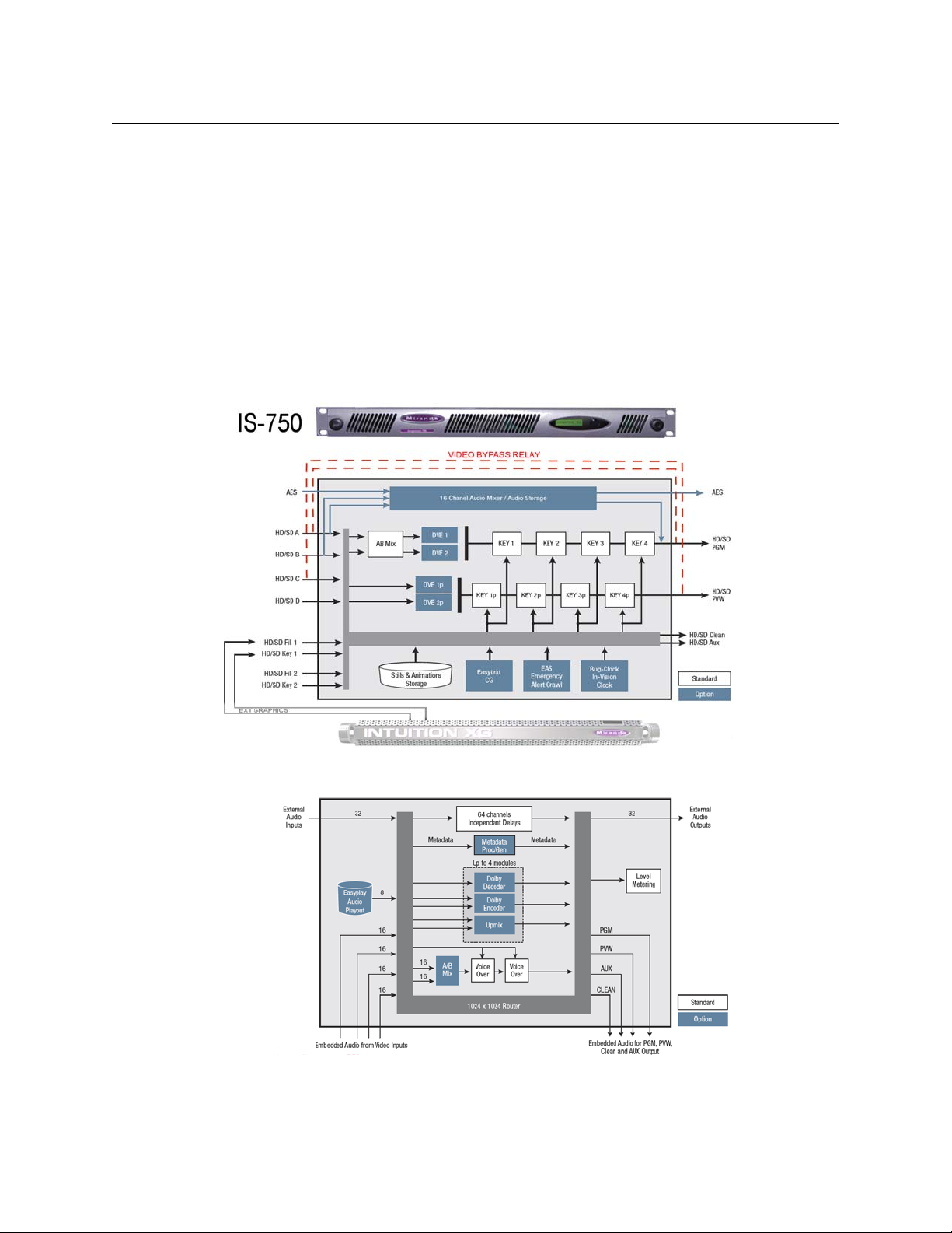
• Built-in web server providing front panel control, system information, message logs and
diagnostics, media management, audio templates, system backup and restore, and software
upgrades.
• Front panel diagnostics for configuration, temperature, power supplies, and PLL.
• SNMP support for system monitoring and diagnostics.
• Configuration tool (the Imagestore 750 Configurator) for system setup and graphical audio
route management.
Architectural Summary
The following block diagrams shows the functions of the Imagestore 750:
Imagestore 750
User Manual
Fig. 2-1: Simplified Functional Diagram of the Imagestore 750 (Video)
Fig. 2-2: Simplified Functional Diagram of the Imagestore 750 (Audio)
9
Page 26

Introduction
Architectural Summary
The Imagestore 750 has 8 video inputs, HD or SD. Each SDI video input feeds the internal video
buses (program, preview, monitor, and clean-feed) and one parallel audio-processing block. The
Imagestore 750 has line FIFOs for all 8 SDI inputs for timing adjustment. Embedded audio can
be de-embedded from any 4 of the 8 inputs, and then be manipulated as required by the
Imagestore 750’s audio engine.
The program video bus (PGM) has an A/B mixer, four keying layers and an optional dual-window
2D DVE. The A/B mixer allows the PGM output to be transitioned between two SDI video
streams. Each of the keying layers may be fed graphics content from its own dedicated store or
any of the three available external fill and key pairs, and then keyed over the background video.
The stores can be loaded with a still image, animation, Easytext template, analog/digital clock,
or Emergency Alert System (EAS) crawl. All available media files are stored in the media library
(compact flash or hard disk, depending upon the option purchased) and then loaded into the
internal stores on demand. The dual-window 2D DVE is used to create picture-in-picture
squeeze effects which can be dynamically positioned between different keying layers on the
program video bus.
The preview video bus (PVW) has four keying layers and an optional dual-window 2D DVE. Each
keying layer shares graphics content with the corresponding program keying layer, but can be
controlled independently in order to preview graphics before they are viewed on-air. Similarly
the dual-window 2D DVE can be used to preview DVE moves before they are played on-air.
The clean-feed (CLN) and monitor (MON) video outputs allow a number of different internal
points within the video system to be sampled and viewed for partial branding or monitoring
purposes. For example, the CLN output can take its output from DSK3 of the program bus to
show a partially branded version of the program output, without a station logo.
A fail-safe mechanical video relay bypass connects the A video source to the program output
directly and connects the C video input to the preview output (PVW) directly when a power
supply problem occurs. The bypass mechanism is shown in Figure 2-1.
The Imagestore 750’s audio engine accepts audio inputs from four embedded SDI feeds, 16 AES
pairs, and from the multi-channel Easyplay2 audio clip player, which gives simultaneous playout
of up to four audio clips sharing a total of 16 channels. The audio engine provides 16-channel A/
B mixing and multiple voice-overs. During voice-overs, background audio is automatically
ducked. Silence detection automates control of multiple independent voice-overs fed from the
same Easyplay clip. (Silence detection is typically used in a multi-language broadcast
environment.)
Optional audio modules can be added that provide integrated support for Dolby encoding and
decoding, and stereo-to-5.1 up-mixing. The audio engine complements Dolby and up-mixing
with advanced metadata processing. Audio description (AD) allows a background commentary
track to be mixed with the background audio for people who are visually impaired.
One of up to 16 possible tap points from the audio engine can then be dynamically assigned to
each of the available unit outputs, to the four embedded outputs (PGM, PVW, CLN, MON), to the
external AES outputs, and to the level metering.
The audio engine is configured using the ‘Audio Graph’ page of the Imagestore 750
An Ethernet interface provides rapid transfer of images and animations using Media Conversion
Software (MCS) and other third-party media management applications. This interface also
allows the transfer of images between a PC and the Imagestore 750 using Miranda’s Vertigo
Xplorer.
Configurator.
10
Page 27
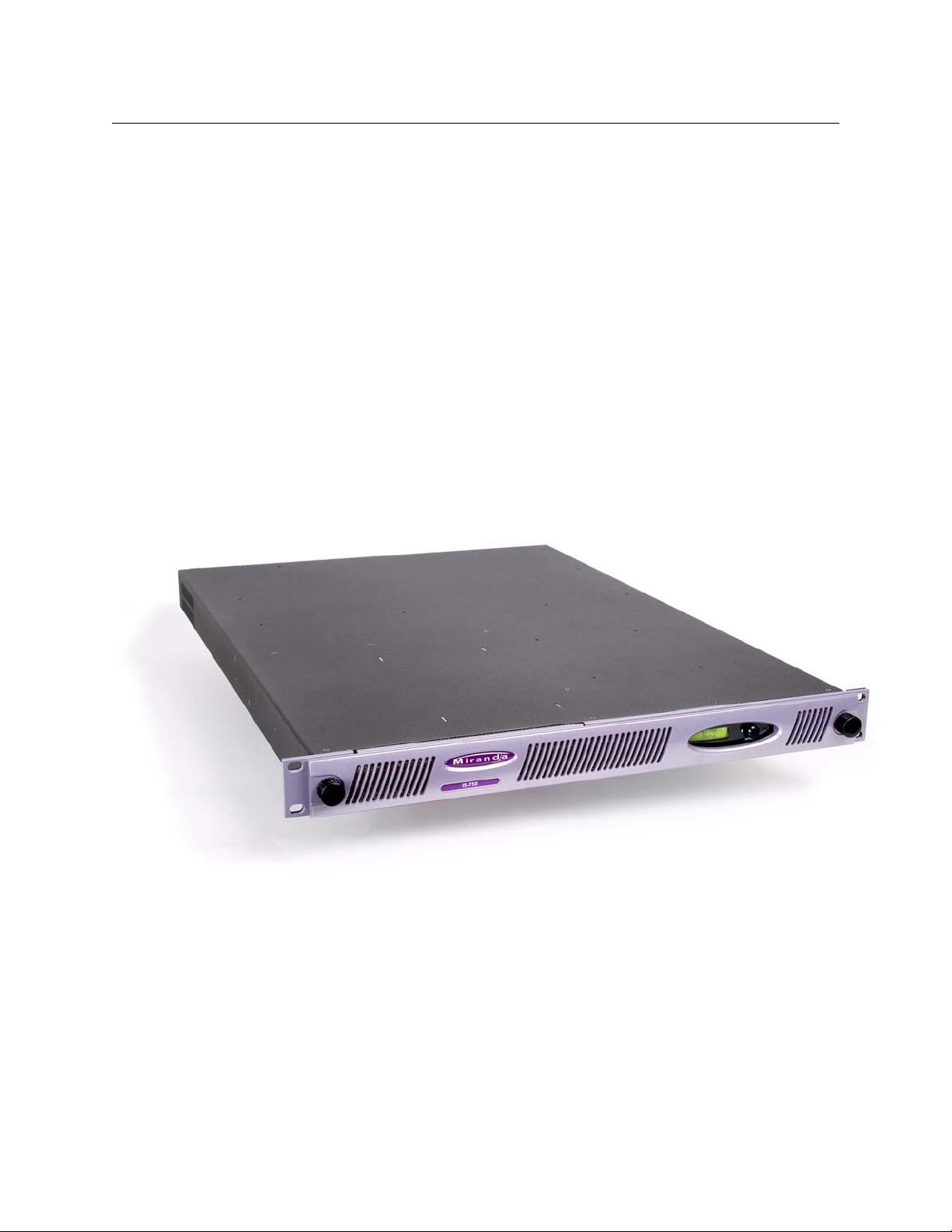
The Media Conversion Software (MCS) and its documentation is available on a CD and includes:
• Audio Builder
• Clip Builder
• Clock Builder
• Batch Converter
• Animation Builder
• DVE Editor
Miranda’s Vertigo Xplorer provides for the transfer and management of still images and animations. See the Xplorer User Guide for details regarding Xplorer.
Files may also be transferred between a PC workstation and the Imagestore 750 using a secure
FTP program, DOS-formatted USB device, or the Imagestore 750’s web page. (The files must be
in an appropriate format.) Miranda’s Media Conversion Suite (MCS) applications are designed for
this purpose and ship with each Imagestore 750.
Physical Features
The Imagestore 750 is a 1RU master control and branding processor.
Imagestore 750
User Manual
Fig. 2-3: Imagestore 750
It has a small control panel and a USB port at the front, and a number of connectors at the rear.
11
Page 28
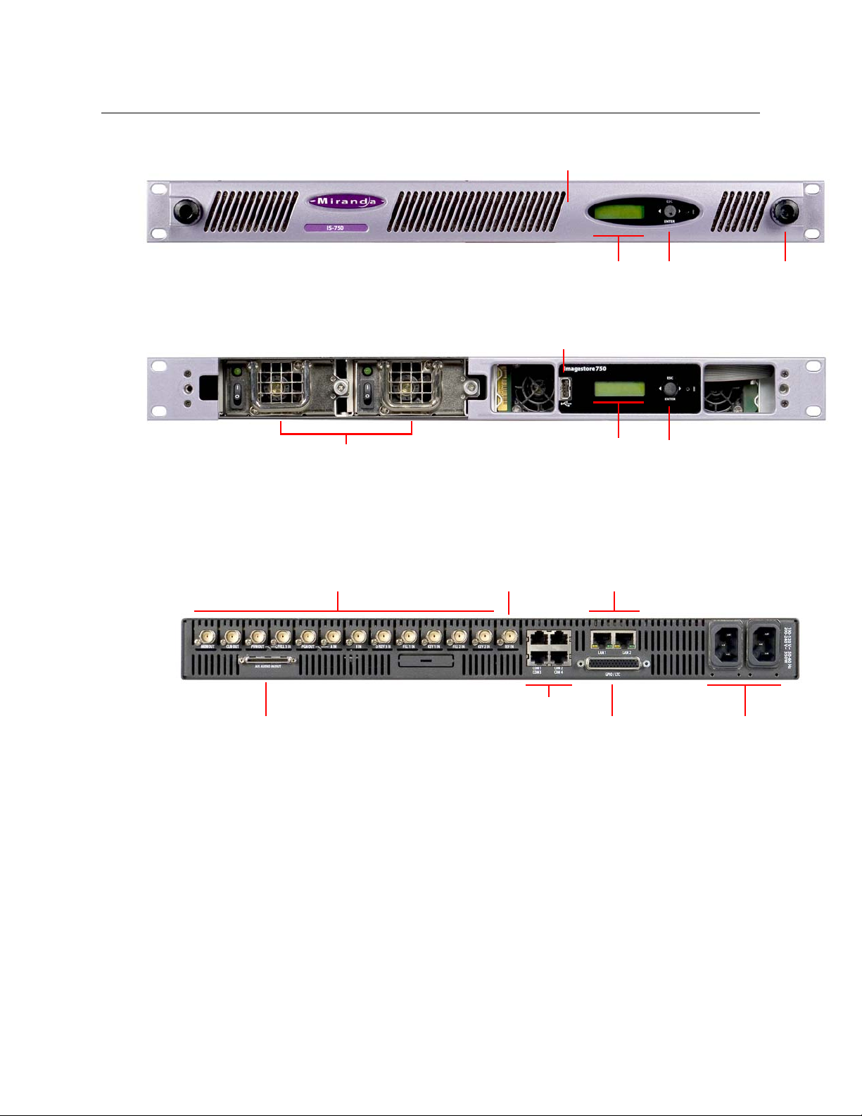
Introduction
Thumbscrews (2)JoystickLCD
USB Port (Hidden by Fascia)
Power Supplies (2)
JoystickLCD
USB Port (Hidden by Fascia)
AC Connectors (2)GPIO ConnectorAES Connector
COM Ports (4)
LAN Ports (2)Video Ref. Video Inputs and Outputs
Physical Features
The front panel’s fascia is removable. Turn the thumbscrews to remove or replace it:
Fig. 2-4: Imagestore 750 front panel
Behind the fascia are bays for two removable power supply modules and a USB port:
Fig. 2-5: Imagestore 750 front panel with fascia removed
The USB port can be used for loading new license options, load and saving configurations,
saving device diagnostics, copying image, animation, and audio files to the Imagestore 750, and
booting the Imagestore 750 from USB for software upgrades.
The rear panel connections are arranged as shown:
Fig. 2-6: Imagestore 750 rear panel
The AES connector provides 16 AES input pairs and 16 AES output pairs.
The GPIO connector provides 16 GPIs (individually configurable as an input or output), LTC
terminals, and 4 RS-485 ports.
The COM ports (RJ45) can be configured as RS-422 or RS-232.
The LAN ports (RJ45) are for Ethernet connections. These are either “bonded” to the same IP
address for networking redundancy, or un-bonded on independent IP addresses to separate
media management from automation control.
The video inputs are A, B, C/Fill-3, D/Key-3, Fill-1, Key-1, Fill-2, and Key-2, supporting HD and SD
video formats. See
(C and D inputs can be used as fill and key inputs if the Imagestore 750 is so configured.)
The video outputs are PGM Out, PVW Out, CLN Out, and MON Out, supporting HD and SD video
formats.
Video Frame Rates on page 212 for details.
12
Page 29

Imagestore 750
Joystick
User Manual
The Front Panel
The front panel has a 16×2 alphanumeric display which is used for status and for configuration.
It is used in connection with a 4-position joystick:
Fig. 2-7: Imagestore 750 front panel display and joystick
Using the joystick, an operator can navigate efficiently through a fairly large menu system. The
menu system is hierarchical. See Appendix A for a complete description of the menu.
Moving the joystick down has two functions, depending on the current position in the menu
system.
• It accesses the first item in the list of items belonging to the menu currently displayed.
• If the current menu item has no list of items (i.e., it is a leaf node in the menu tree), the item is
an operand and moving the joystick down selects the value of the operand as the current
value of the parameter it represents.
Moving the joystick up causes the display to go up one level in the menu tree. At the top level,
moving the joystick up has no effect.
Moving the joystick left or right selects the previous, or next, item in the list of items at the
current menu level.
Symbols and Conventions
Where this user manual discusses joystick input, it represents the 4 positions of the joystick with
the terms ‘[esc]’, ‘[enter]’ or the arrow icons
At times, additional symbols are shown on the top line of the display, at the right hand edge.
These highlight the state of either the A/B Mixer (video or audio) or the keyers. These symbols
represent:
ASource A
BSource B
– Intermediate state, transition being processed.
↑ Image/voice-over keyed up (to air)
↓ Image/voice-over keyed down (from air)
BFade to black
SFade to silence
and .
13
Page 30

Introduction
Physical Features
Page Intentionally blank
14
Page 31

Chapter 3 presents several applications of the Imagestore 750.
Topics
Three Scenarios . . . . . . . . . . . . . . . . . . . . . . . . . . . . . . . . . . . . . . . . . . . . . . . . . . . . . . . . . . . . . . . . . . . . page 15
Agile Audio Handling . . . . . . . . . . . . . . . . . . . . . . . . . . . . . . . . . . . . . . . . . . . . . . . . . . . . . . . . . . . . . . . page 19
Three Scenarios
Downstream Branding
In many specialty channels, branding is performed downstream of a dedicated video server. In
this scenario, an Imagestore 750 provides a combination of logo insertion, animations, basic
text crawls and picture-in-picture DVE squeeze effects. Moreover, advanced graphics can be
achieved using an Intuition XG, advanced audio processing (Dolby decode/encode, up-mix, AD).
Voice-over mixing can also be applied to the background signal. In this scenario, everything is
under control of automation, but an RCP-BR control panel can also be used for branding control.
Applications
Fig. 3-1: Downstream Branding
15
Page 32

Applications
Three Scenarios
Master Control Switching
The Imagestore 750 can be used as a traditional master control switcher. Automation controls
arm-and-take transitions involving router sources for A/B mixing, keyer control, DVE squeezes,
voice-overs and Intuition XG graphics. iMC panel operators can take manual control of the
channel processor whenever it is required to override automation. Output from the channel
processor is fed back to the station router for distribution to the outside world; media servers,
local monitor walls, and so on. Sources are grouped to make it easier to manage multiple
sources.
The Imagestore 750 is the hub of this control system, managing routing through an NV9000
router control system and using the advanced graphics of an Intuition XG. If the Imagestore 750
ever fails, it can be quickly bypassed using a redundant backup channel.
16
Fig. 3-2: Master Control Switching
See Chapter 5, Master Control, for details regarding the iMC master control system.
Page 33

Imagestore 750
User Manual
Branding Insertion Options for Intuition XG
Advanced branding from the Intuition XG (including audio embedded in the fill signal) can be
inserted into the program output in several different ways.
Fill/Key Branding Insertion
This example feeds the video source into the Imagestore 750, which performs A/B mixing, DVE
squeezes and basic branding. The Intuition XG’s fill and key outputs also feed rich multi-layered
graphics into one of the Imagestore 750 keying layers, contributing to the final program output.
All audio mixing and processing is performed by the Imagestore 750, although the Intuition XG
can supply voice-overs in its fill signal.
Fig. 3-3: Fill/Key Branding Insertion
A benefit of fill/key branding insertion is that the graphics device is not in the direct signal path
and will not affect output in the event of a failure. Also both devices can be controlled as a single
“channel processor” by automation and iMC control panels. The main disadvantage is that it is
difficult to synchronize Intuition XG graphics with DVE squeezes.
Downstream Branding Insertion
This example feeds the video source to the Imagestore 750, which performs A/B mixing of video
and audio plus performs advanced audio processing such as Dolby decoding or up-mix. Output
from the Imagestore 750 is then passed downstream into the Intuition XG which performs DVE
squeezes and applies rich multi-layered graphics to give the final program output. The Intuition
XG can also play out and mix audio clips with the program output as embedded audio.
17
Page 34

Applications
Three Scenarios
Fig. 3-4: Downstream Branding Insertion
A benefit of downstream branding insertion is that the DVE and branding are performed by the
same device, which is much simpler to configure and automate. Also AFD data can be used for
graphics positioning. Dolby E and Dolby Digital (AC-3) can be passed through the Intuition XG,
but cannot be manipulated. The main disadvantage is that the graphics device is in the direct
signal path. In addition, this scenario is not supported by the master control option.
In-Stream Branding Insertion
This example feeds the video source to the Imagestore 750, which starts by performing A/B
mixing of video and of audio. Output from the A/B mixer is then routed into the Intuition XG,
which performs DVE squeezes and applies rich multi-layered graphics to the video signal. The fill
output of the Intuition XG then feeds one of the Imagestore 750’s keying layers to provide the
final program video output. Advanced audio mixing and processing (Dolby decode/encode, upmix, AD) is performed by the Imagestore 750 in parallel with video through the Intuition XG. The
Intuition XG can play out and mix audio clips with its output as embedded audio to be used by
the Imagestore 750 as a voice-over. Although simple processing of PCM background audio
could be performed by the Intuition XG, there are better monitoring possibilities if it is always
done by the Imagestore 750. Further, there will be no inconsistencies in audio output if the Intuition XG is ever removed from the signal path.
18
Page 35

Fig. 3-5: In-Stream Branding
Station
Router
Dolby E
Decode
English 5.1 PCM
Spanish 2.0 PCM
A
B
English 5.1 Dolby E
Spanish 2.0 PCM
English 5.1 Dolby E
Spanish 2.0 PCM
Dolby E
Decode
A/B
Mix
VOs
Dolby E
Encode
Imagestore 750
User Manual
This scenario combines the advantages of both “fill/key branding insertion” and “downstream
branding insertion.” The Imagestore 750 acts as a robust bypass for the Intuition XG. If the Intuition XG ever fails, the Imagestore 750 keyer receiving Intuition XG graphics is cut down and an
unbranded (or lightly-branded) version of the original video source will continue to be output
without any break in signal integrity.
Agile Audio Handling
Video sources feeding the Imagestore 750 can have different input audio configurations, some
including Dolby data and others, PCM audio. To maintain a constant output audio mapping as
the A and B inputs switch between different router sources (or sources change audio format
dynamically), the Imagestore 750 mixes between different audio configurations by selectively
using Dolby decode, up-mix and Dolby encode audio modules.
Example 1
In this example, sources that feed the Imagestore 750 inputs will always be in one of two
possible audio formats: 5.1 PCM + 2.0 PCM and 5.1 Dolby E + 2.0 PCM.
The two input audio streams are passed into Dolby E decoders which dynamically convert audio
to a format suitable for A/B mixing (5.1 PCM + 2.0 PCM). The audio A/B mixer then transitions
(fades or cuts) between sources, a voice-over can be mixed, and the output is encoded back into
the required Dolby E configuration (5.1 Dolby E + 2.0 PCM).
Fig. 3-6: Agile Audio Handling - 2 Dolby Decodes and an Encode
19
Page 36

Applications
Station
Router
Dolby E
Decode
English 5.1 PCM
Spanish 2.0 PCM
A
B
English 5.1 Dolby E
Spanish 2.0 PCM
English 5.1 Dolby E
Spanish 2.0 PCM
Dolby E
Decode
A/B
Mix
VOs
5.1 Ch
Up-Mix
5.1 Ch
Up-Mix
English 2.0 PCM
Spanish 2.0 PCM
Agile Audio Handling
Three of a possible four audio module slots are used.
Example 2
In this example below, sources that feed the Imagestore 750 inputs will always be in one of three
possible audio formats:
The two input audio streams are passed into Dolby E decoders and 5.1 up-mix modules which
dynamically convert audio into a fixed format suitable for A/B mixing (5.1 PCM + 2.0 PCM). The
audio A/B mixer then transitions (fades or cuts) between the sources, and a voice-over can be
mixed into the output in the required configuration (5.1 PCM + 2.0 PCM).
• 5.1 PCM + 2.0 PCM
• 5.1 Dolby E + 2.0 PCM
• 2.0 PCM + 2.0 PCM.
Fig. 3-7: Agile Audio Handling - 2 Dolby Decodes and 2 UpMixes
All four audio module slots are used in this case
20
Page 37

Features
Chapter 4 presents the important characteristics and functions of an Imagestore 750 in detail.
Topics
Video Standards . . . . . . . . . . . . . . . . . . . . . . . . . . . . . . . . . . . . . . . . . . . . . . . . . . . . . . . . . . . . . . . . . . . . page 21
Reference . . . . . . . . . . . . . . . . . . . . . . . . . . . . . . . . . . . . . . . . . . . . . . . . . . . . . . . . . . . . . . . . . . . . . . . . . . . page 22
Audio Processing . . . . . . . . . . . . . . . . . . . . . . . . . . . . . . . . . . . . . . . . . . . . . . . . . . . . . . . . . . . . . . . . . . . page 25
Video A/B Mixing . . . . . . . . . . . . . . . . . . . . . . . . . . . . . . . . . . . . . . . . . . . . . . . . . . . . . . . . . . . . . . . . . . . page 31
Store Memory . . . . . . . . . . . . . . . . . . . . . . . . . . . . . . . . . . . . . . . . . . . . . . . . . . . . . . . . . . . . . . . . . . . . . . page 32
Keying Graphics . . . . . . . . . . . . . . . . . . . . . . . . . . . . . . . . . . . . . . . . . . . . . . . . . . . . . . . . . . . . . . . . . . . . page 32
DVE (for Program and Preview) . . . . . . . . . . . . . . . . . . . . . . . . . . . . . . . . . . . . . . . . . . . . . . . . . . . . . page 41
Video Frame Delays . . . . . . . . . . . . . . . . . . . . . . . . . . . . . . . . . . . . . . . . . . . . . . . . . . . . . . . . . . . . . . . . page 43
Preview Output . . . . . . . . . . . . . . . . . . . . . . . . . . . . . . . . . . . . . . . . . . . . . . . . . . . . . . . . . . . . . . . . . . . . . page 43
Clean-Feed Output . . . . . . . . . . . . . . . . . . . . . . . . . . . . . . . . . . . . . . . . . . . . . . . . . . . . . . . . . . . . . . . . . page 45
Monitor Output . . . . . . . . . . . . . . . . . . . . . . . . . . . . . . . . . . . . . . . . . . . . . . . . . . . . . . . . . . . . . . . . . . . . page 46
General Purpose Interface (GPI) . . . . . . . . . . . . . . . . . . . . . . . . . . . . . . . . . . . . . . . . . . . . . . . . . . . . . page 47
Macros . . . . . . . . . . . . . . . . . . . . . . . . . . . . . . . . . . . . . . . . . . . . . . . . . . . . . . . . . . . . . . . . . . . . . . . . . . . . . page 50
Graphics Co-Processors . . . . . . . . . . . . . . . . . . . . . . . . . . . . . . . . . . . . . . . . . . . . . . . . . . . . . . . . . . . . . page 52
Closed Captions . . . . . . . . . . . . . . . . . . . . . . . . . . . . . . . . . . . . . . . . . . . . . . . . . . . . . . . . . . . . . . . . . . . . page 56
Timecode . . . . . . . . . . . . . . . . . . . . . . . . . . . . . . . . . . . . . . . . . . . . . . . . . . . . . . . . . . . . . . . . . . . . . . . . . . . page 56
Message Logging . . . . . . . . . . . . . . . . . . . . . . . . . . . . . . . . . . . . . . . . . . . . . . . . . . . . . . . . . . . . . . . . . . . page 57
System Configuration . . . . . . . . . . . . . . . . . . . . . . . . . . . . . . . . . . . . . . . . . . . . . . . . . . . . . . . . . . . . . . page 58
Video Bypass . . . . . . . . . . . . . . . . . . . . . . . . . . . . . . . . . . . . . . . . . . . . . . . . . . . . . . . . . . . . . . . . . . . . . . . page 58
Major features of the Imagestore 750, including master control and advanced audio, are covered
in their own chapters.
Video Standards
Output
The Imagestore 750 can receive and transmit the following SDI video standards:
525i / 59.94
625i / 50
1920 x 1080i / 59.94
1920 x 1080i / 50
1280 x 720 / 59.94
1280 x 720 / 50
See Video Frame Rates on page 212 for additional detail.
Hz SMPTE 259M-1997 270 Mb/s
Hz SMPTE 259M-1997 270 Mb/s
Hz SMPTE 274M-1998 1.485 Gb/s
Hz SMPTE 274M-1998 1.485 Gb/s
Hz SMPTE 296M-2001 1.485 Gb/s
Hz SMPTE 296M-2001 1.485 Gb/s
21
Page 38

Features
Reference
Propagation Delay
With the DVE in circuit, the delay through the Imagestore 750 is 2 interlaced fields or 2 progressive frames depending on the video standard. See DVE (for Program and Preview) on page 41 for
more information.
Without the DVE in circuit, the delay through the Imagestore 750 can be up to 1 line. The delay
consists of input line’s FIFO depth delay (which depends on the adjustment of the reference
timing) plus a minimum video processing propagation delay.
The video propagation delay for the Imagestore 750 is as follows:
Video Standard Propagation Delay
525i / 59.94
625i / 50 Hz 5.4 ms
1920 × 1080i / 59.94 Hz 2.6 ms
1920 × 1080i / 50
1280 × 720p / 59.94 Hz 2.6 ms
1280 × 720p / 50 Hz 2.6 ms
Table 4-1: Video Standard Propagation Delay
Hz 5.4 ms
Hz 2.6 ms
Reference
Embedded audio delays are different from those of video. Embedding and de-embedding
circuits are required by SMPTE standards to buffer many samples before processing. The
Imagestore 750’s audio “through-path” propagation delay is measured in audio samples (~20
per audio sample at 48
kHz). Because audio sample duration is significant compared to video
line duration, embedded audio samples present on input video line L will be processed, then
output, on video line L + N, where N is variable and depends on both the video standard and
line L. As a rough guide, N is generally 5 to 12 lines.
Reference Types
The Imagestore 750 locks to one of the following inputs, in order of priority:
REF IN Analog reference input, if present and compatible
PGM IN If present and at the correct video standard
Otherwise the Imagestore 750 will free-run.
μs
22
Page 39

Imagestore 750
User Manual
The compatibility matrix between REF IN type and output video format is shown here:
REF IN Type
525i / 59.94
625i / 50
1080i / 59.94
1080i / 50
720p / 59.94
720p / 50
525i / 59.94
625i / 50
1080i / 59.94
1080i / 50
720p / 59.94
Output Video Format
720p / 50
Table 4-2: Reference In compatibility with Output Video Standard
Adjusting Reference Timing
Always adjust reference timing off-air because it can result in a loss of picture in downstream
equipment. Errors can occur in the SDI stream as the adjustment is taking place.
The Imagestore 750 has one FIFO on each input for simplified system timing. You can modify the
reference offset using the front panel menu. Select Setup > Reference > Offset.
Then choose either:
Lines/Samples
Lines/uS
Use the front panel arrows to increase or decrease the offset value. For any video standard, the
factory default reference timing is 0 lines plus half the length of a video line. This setting buffers
about half a video line for inputs that are timed to a reference offset of + 0 lines + 0 samples (or
+ 0 lines + 0
ms).
Reference adjustment affects the line number marking of the output stream. The reference
must be adjusted to match the input signal timing of the local facility. Ancillary data such as
timecode, captions and audio metadata may be missed by downstream equipment if they are
not present on the same line on which they were input. If the output reference timing is not set
correctly, problems might be seen such as:
• Loss of timecode.
• Loss of closed captions.
• Errors in embedded audio.
• Errors in Dolby E streams.
Note that reference adjustment affects the line number marking of the output stream. The reference must be adjusted to match the input signal timing of the local facility.
An SDI data analyzer is needed to monitor the timing of the SDI input sources and the outputs
with respect to the facility reference.
23
Page 40

Features
Reference
Clean switching between the inputs is made possible by buffering the input FIFOs to co-time
them before processing. The reference timing adjusts the active depth of the FIFOs to accommodate small timing differences between the input signals.
The shortest video processing delay from any input through the Imagestore 750 to the program
output occurs when the input FIFO depth is at its minimum. By increasing the output reference
timing with respect to PGM IN, the FIFO depth is lengthened, up to its maximum of 1 line.
To be valid, the input timing value must be negative. If the value is not negative, the refer-
ence offset must be adjusted so that the input timing value is negative.
HD Example (1080i)
Timing is dependent on the relative phase between the SDI input and the reference. The
following example illustrates how to set up HD signals with a tri-level sync to achieve the
minimum delay through the unit:
• Assume that the HD input arrives 3 μs later than the associated tri-level sync (+0 line +3 ms).
• Assume that the minimum processing delay is about 2.6 ms for HD.
Example: Because PGM IN is 3
later than PGM IN, the minimum starting point at which to set the reference timing is (0 line
+3
ms) + 2.6 ms= 0 line + 5.6ms.
The reference timing must now be increased so that some data is buffered in the line FIFOs. In
this example, the line FIFO is almost empty. This is a very undesirable timing point because the
FIFO is on the threshold of going from empty to full if the input timing changes slightly,
resulting in a 1-line vertical shift. Furthermore, the whole video picture may show corruption
precisely at the FIFO empty point.
Adding half a video line to the above reference timing provides enough buffering to accommodate the largest timing differences when the input is switched to a source that is not correctly
co-timed. Co-timed inputs will then have approximately half a line buffered in their FIFOs. Any
sources that arrive earlier or later will increase or reduce the FIFO depth respectively.
The following table shows line lengths of the SDI standards:
ms later than the tri-level sync and PGM OUT is at least 2.6 ms
24
Video Standard Line Length Samples
525i / 59.94 Hz 63.5 ms 1716
625i / 50
1920 x 1080i / 59.94
1920 x 1080i / 50
1280 x 720p / 59.94
1280 x 720p / 50
Table 4-3: Video Line Duration
Half a line at 1080i / 59.94 is approximately 15
the reference timing (in the example) to 0 line + 5.6
Note: If the path delays of the SDI input sources are such that they are all offset from refer-
Hz 64.0 ms 1728
Hz 29.6 ms 2200
Hz 35.5 ms 2640
Hz 22.2 ms 1650
Hz 26.7 ms 1980
ms. To buffer half a line of 1080i / 59.94, increase
ms (+ 15 ms) = 0 line + 20.6 ms.
ence by several lines then adjust the reference by the same number of lines to align the
output to the unusual input timing. Then add 10 to 20 microseconds to give some buffering
in the line FIFOs.
Page 41

Audio Processing
Audio processing requires the IS-750-Audio6 or IS-750-Audio16 audio option to be enabled.
The audio engine has the following characteristics:
• Input selection from embedded SDI (4 feeds having 16 channels) or external AES (32 chan-
nels).
• A/B mixing of multi-channel audio sources for cuts and variable rate fades (1–48 channels).
• Multi-channel voice-overs for program and preview with background automatically ducked
during voice-over (1–48 channels).
• Easyplay clip storage and playout of four streams sharing 16 audio channels.
• Ability to associate Easyplay audio files automatically with video image/animation files.
• “Wide” shuffles and control of gain level, trim, phase, and mute for each channel (1–48 chan-
nels).
• Dolby E and Dolby Digital (AC-3) decoding and encoding.
• 5.1 Up-mixing using Linear Acoustic’s AutoMAX-II
• Advanced metadata processor with support for embedded metadata, metadata switching,
metadata generation, dynamic metadata modification, metadata pass-through, and metadata delay.
• Audio description (AD) with automated mixing of commentary track for the visually
impaired.
• Silence detection that automates the control of multiple independent voice-overs fed from
the same Easyplay clip.
• Fade-to-silence (1–48 channels).
• Configurable audio delays (48 channels shared between 6 delay banks).
• Output re-embedded onto PGM, PVW, CLN and MON outputs (16 channels) or external AES
(32 channels).
• Audio level metering (48 channels).
• Dynamic selection of audio preview points and metering through output multiplexors (1–48
channels, 16 sources).
• All internal processing is 24-bit at 48 kHz.
• Graphical configuration tool (the ‘Audio Graph’ page of the Imagestore 750 Configurator) for
creating, viewing, and editing audio routing.
TM
technology.
Imagestore 750
User Manual
25
Page 42

Features
Audio Processing
The following inputs and outputs are available to the audio engine:
Audio Inputs Channels Audio Outputs Channels
SDI Feed 1 (embedded) 16 SDI PGM (embedded) 16
SDI Feed 2 (embedded) 16 SDI PVW (embedded) 16
SDI Feed 3 (embedded) 16 SDI CLN (embedded) 16
SDI Feed 4 (embedded) 16 SDI MON (embedded) 16
AES Inputs 32 AES Outputs 32
Easyplay2 16 Level Meters 48
Silence 1
Tes t Ton e 1
Table 4-4: Audio Engine Inputs and Outputs
Audio Graph
To set up audio routing in the Imagestore 750 Configurator, drag audio blocks onto the ‘Audio
Graph’ view. Then connect appropriate pins between input and output blocks.
Please see Chapter 8, Imagestore 750 Configurator, for detailed information about the
Imagestore 750 Configurator.
Please see Audio Graph on page 161 for more details of the various audio blocks which are
available for the Imagestore 750.
Figure 4-1, following, shows a sample of the ‘Audio Graph’ page.
In Figure 4-1, the 16 channels of two embedded SDI feeds are mixed at the A/B mixer. An AES
voice-over is then applied before the audio is sent to SDI PGM output. This example does not
incorporate typical control blocks for features such as input gain, input shuffling, fade to silence,
output gain, preview and meter multiplexing or meters.
26
Page 43

Imagestore 750
User Manual
Fig. 4-1: Imagestore 750 Configurator - Audio Graph view
Some audio blocks are controlled by automation, and others can be set up to follow other
system states automatically. For example, audio A/B mixing might follow video A/B mixing and
Easyplay clips might drive voice-overs or follow the up/down state of keying layers on program
or preview.
Sample Audio Graph Templates
The Imagestore 750 Configurator provides many different ‘Audio Graph’ templates so that you
can build custom audio setups. These are the templates:
• AB Mixer
16-channel embedded A/B mix.
16-channel embedded A/B mix with 2 channel AES voice-over (EAS).
27
Page 44

Features
Audio Processing
16-channel embedded A/B mix with 16 channel AES voice-over.
• AB Mixer with Easyplay
16-channel embedded A/B mix with 16 channel AES voice-over and 16 channel Easyplay
voice-over.
16-channel embedded A/B mix with 16 channel AES voice-over and multilingual Easyplay
setup (independent automatic duck control of Easyplay channels 6-6-2-2).
16-channel embedded A/B mix with 16 channel AES voice-over and 8 channel Easyplay
voice-over (independent control of voice-overs on PGM and PST).
16-channel embedded A/B mix with 16 channel AES voice-over and 8 channel Easyplay
voice-over (independent control of voice-overs on PGM and PST, Easyplay follows video
stores and keyers).
• Pass-through (non-A/B mix)
16-channel embedded pass-through with 2 channel AES voice-over (EAS).
16-channel embedded pass-through with 16 channel AES voice-over.
• Pass-through (non-A/B mix) with Easyplay
16-channel embedded pass-through with 16 channel AES voice-over and 16 channel Easy-
play voice-over.
16-channel embedded pass-through with 16 channel AES voice-over and multilingual Easy-
play setup (independent automatic duck control of Easyplay channels 6-6-2-2).
• Dolby AB Mixer
Dolby E in (Dolby E out) embedded AB mix with 8 channel AES voice-over.
Dolby E/PCM in (Dolby E out) embedded AB mix with 8 channel AES voice-over.
Dolby E/PCM/up-mix in (PCM out) embedded AB mix with 8 channel AES voice-over.
Dolby E/PCM/up-mix in (PCM out) embedded AB mix with 8 channel AES voice-over and
Easyplay voice-over.
• Dolby Pass-through (non AB mix)
Dolby E/PCM in (Dolby E out) with 8 channel AES voice-over.
Dolby E/PCM/up-mix in (Dolby E out) with 8 channel AES voice-over.
Dolby E/PCM/up-mix in (Dolby E out) with 8 channel AES voice-over and Easyplay voice-
over.
• Test Setups
Test tone to all outputs.
• Each template is described in the Imagestore 750’s web page, listing the following details:
• Functional description
• Inputs
• Outputs
• Preview modes
28
Page 45

Imagestore 750
User Manual
To select a template upon which to build, choose ‘Import Audio Graph’ from the Imagestore 750
Configurator’s ‘File’ menu. Then choose ‘From Device Template . . .’ in the submenu and select
the appropriate filename in the dialog that appears subsequently:
Fig. 4-2: Import Audio Graph dialog
(See Audio Templates on page 182 for more information.)
Embedded SDI Audio
Embedded audio processing requires the IS-750-Audio6 or IS-750-Audio16 audio option to be
enabled.
Audio can be de-embedded from 4 of the 8 available SDI inputs and re-embedded in the 4 SDI
outputs. The IS-750-Audio6 option provides 4 channels of de-embedding for each feed, and the
IS-750-Audio16 option provides 16 channels of de-embedding for each feed.
External AES Audio
There are 16 AES pairs (32 discrete channels) available for both audio input and audio output.
The AES inputs and outputs are presented on a 68-pin SCSI D-connector to enable wiring of
mating connectors to a 1RU breakout box. (The order codes for those products are ABT-32-32D110 and ABT-32-32-D75.) All AES inputs and outputs are sampled at 48
video.
kHz and locked to
Audio A/B Mixing
Audio A/B mixing requires that the video A/B mixing option be enabled. It is not available for
the IS-750-LOGO.
The Imagestore 750 allows A/B mixing of multi-channel audio sources for cuts and variable rate
fades with mixes being up to 48 channels wide. Audio can be configured to follow the video A/B
mixer position automatically, or it can be controlled independently for lead/lag or breakaways.
Depending on the type of video A/B mix, audio mixes pass through either silence (V-fades) or a
50% mix of the A and B sources (X-fades).
29
Page 46

Features
Voice-Over Preset
Duck Preset
Voice-Over Audio
Background Audio
Audio Processing
Voice-Overs
Voice-overs adjust the combined levels of the background audio and incoming voice-over so
the audio level does not exceed the original background volume. The diagram shows how the
‘duck’ and voice-over presets adjust the actual audio levels.
Fig. 4-3: Audio level during Voice-Over - duck and voice-over preset
The duck value is the amount by which the background audio level is attenuated when the
voice-over is fully on. The voice-over preset value is the level of the voice-over audio when the
voice-over is fully on. Both values are given in decibels.
The Imagestore 750 Configurator’s ‘Audio Graph’ page allows you to define 8 independent
voice-overs for use on the program bus. There are also 8 preview voice-overs for the preview
bus which can be set to cut up or down automatically based on the arm state of the corresponding program voice-over. (See Audio Mix Blocks on page 165 for more information.)
Easyplay
Easyplay2 requires the IS-750-EP16 option to be enabled.
Note: In software versions 3.1 and later, 16 channels of audio clip playout are also enabled by
IS-750-EP2 and IS-750-EP8 options.
The Easyplay feature allows digital audio clip storage and playout of up to four independent
streams sharing a total of sixteen audio channels. Many variations are possible, such as:
Name Description Streams Channels
16 One stream playing out the widest possible audio clips 1 16
2.0 + 5.1 One language with two streams of different width 2 8
2.0 + 5.1 + 2.0 + 5.1 Two languages each with two streams of different
widths
2.0 + 2.0 Two stereo streams under independent control 2 4
2.0 + 2.0 + 2.0 + 2.0 Four stereo streams under independent control 4 8
Table 4-5: Example Easyplay2 streams and channels possibilities
Easyplay audio clips are often associated with one of the 16 available voice-overs on PGM and
PVW. The associated voice-over may be configured to fade up automatically when the Easyplay
stream starts playing, and fade down automatically when the Easyplay stream stops. Alternatively, the Easyplay stream can be configured to start or stop playing when its associated voiceover is faded up or down.
You can place Easyplay in a mode in which it follows video layers cuts, fades, loads and unloads
automatically. In this mode, audio clips are loaded by association with image file names, and the
audio clips play out (or stop) automatically when the keyer associated to the media file is cut up
(or down). The association may be made with either program or preview keyers.
416
30
Page 47

The Imagestore 750 supports the following Easyplay audio clip file formats:
.wav Multi-channel WAV files. (This is the preferred format.)
.oxw 2-channel clips created with Audio Builder (available on the MCS CD).
.oxe Multi-channel Imagestore 750 audio file created with Audio Builder.
Imagestore 750
User Manual
All audio clips must be generated at 48
files with 16 bits or 24 bits per sample. WAV files of 24 bits are preferred.
kHz (48,000 samples per second). You can generate WAV
Switching Dolby E Signals
When it is operating in a progressive video standard (720p at 50 or 59.94 Hz) and switching
Dolby E signals, the Imagestore 750 must be given an interlaced reference input
tri-level or SD bi-level analog reference
ence. That is because Dolby E data are locked to the interlaced frame.
— and the Dolby E data must be aligned to this refer-
— such as 1080i
• 720p at 59.94 Hz = 59.94 Hz frame rate
• 1080i at 59.94 Hz = 29.97 Hz frame rate
This requirement applies to all Imagestore 750s that receive Dolby audio data, regardless of
whether any Dolby decode/encode options are enabled. Imagestore 750s without enabled
Dolby options can cut-switch between Dolby data streams, with the transition occurring at the
mid-point of an A/B mix.
Advanced Audio
Chapter 6, Advanced Audio, discusses advanced audio features available in the Imagestore 750.
Please reference these sections:
• Dolby page 105
• Dolby Metadata page 120
• Up-Mix page 133
• Audio Description (AD) page 140
• Silence Detection page 143
• Audio Delays page 146
Video A/B Mixing
The Imagestore 750’s video A/B mixer is fed by any of its input sources or by an external router.
The mixer’s output provides the background video source for the PGM keyers. The mixer can be
dynamically configured either to cut or to fade the video. The Imagestore 750 supports crossfades, cut-fades, fade-cuts, V-fades and U-fades over variable durations, with V-fades transitioning through a predefined color field. You can define the profile of each fade type.
You can configure the audio mix to follow the video mix automatically. Choose Setup >
Audio Setup > Follow Video > A/B Mix at the Imagestore 750’s front panel. Alternatively, you can configure the audio mix to be completely independent of the video.
31
Page 48

Features
Store Memory
Store Memory
The entry-level Imagestore 750 (either an IS-750 or an IS-750-LOGO) provides storage shared
between the 4 keying layers for up to 512 MB of images or animations with their associated
keys. The IS-750-MEM-2GB upgrade expands this storage to 2
The percentage of total store memory allocated to each of the four stores can be configured.
This is useful if you want to assign one keying layer to long animations, and other layers for
smaller logos or external fill/key. There are two ways to change the allocation:
• At the front panel: use ‘Setup > Stores > Stores Memory’.
• In the Imagestore 750 Configurator: choose the ‘Store Manager’ tab under ‘Configuration
Mode’. See Store Manager on page 161.
You should always load media files into the store memory before they are keyed over background video. Stored images and animations can be taken to air by fade or cut transitions. An
automation pre-load capability (command R7) allows the next animation to be loaded in
advance while another animation is on-air, provided there is sufficient memory, to avoid playout
delays on-air. However, it is preferable to use two keying layers to switch between different
media whenever possible.
It is recommended that a media management system is used to transfer media to the Imagestore 750. It is possible to load media using Miranda’s Media Conversion Software (or other
Miranda tools), from a USB device or via an FTP transfer (see the FTP Interface section for more
information).
GB total.
Keying Graphics
Keying is the process of inserting one video signal (a fill signal) into another video signal (the
background signal) according to a third signal (the key signal). The key signal governs the trans-
parency of the fill signal.
Fill and key signals can be obtained from the following sources:
• An external graphics playout device, such as the Intuition XG, fed into a fill and key input.
• Internal media files loaded into store memory.
You can control the following keying parameters:
• Source
• Clip, gain and transparency
• Type
• Sense
• Masking
External Graphics
You can connect an external graphics device or CG to the Imagestore 750’s BNC pairs (Fill-1,
Key-1), (Fill-2, Key-2) or (Fill-3, Key-3). The fill and key signals may then be fed to any of the
supported keying layers and keyed up, or down, as required.
See Keying Parameters on page 39 for a description of the various keying parameters.
32
Page 49

Imagestore 750
User Manual
Internal Media
The following internal image file types can be cut or faded onto any keying layer with an associated store:
Images .oxt
Animations .oxa
Easytext .oxa
Bugclock .oxa
See Keying Parameters on page 39 for a description of the various keying parameters. The
images may be any size up to full-screen. Stored images and their associated keys are processed
at 10-bit resolution (unless the image is stored without a key to save space in which case it is
stored at 8-bit resolution).
Images
Logos and full-frame still images are defined within .oxt image files. The image file embeds
information such as the on-screen position, keying source and keying type. The image’s transparency can be defined in a key image, so effects such as soft edges can be applied.
(See Keying Parameters on page 39 for more information.)
You can ge n erate .oxt image files using one of the following applications:
• Xplorer
• Animation Builder (available on the MCS CD).
Animations
Cell animations are defined in .oxa animation files. The animation file embeds information such
as the on-screen position (for each field or frame of the animation if necessary), keying source
and keying type. The transparency of each frame may be defined in a sequence of key images,
so effects such as soft edges and dynamic fades can be applied. You can define any of the
following loop modes:
• Single shot
• Cycle
• In-loop-out
• Linear control
• Ping-pong
• Multiple loop
(See Keying Parameters on page 39 for more information.)
The maximum length of a cell animation is limited by the available store memory, as determined
by the installed memory and the amount of memory allocated to the associated keyer, in combination with the screen area of the animation. The duration of larger animations, up to full
screen, is reduced proportionally to the area used. Because areas are evaluated at each frame,
animations can change in size with no penalty.
If the last animation frame is completely transparent, then the keyer stays cut up after the
last animation frame. If the last animation frame is small (2×2) then the keyer cuts down after
the last animation frame.
33
Page 50

Features
Keying Graphics
With 128 MB of playout memory per store, a logo that is 1/64 of the screen size can be animated
for just over half a minute. Larger screen sizes or smaller playout memory sizes affect the
maximum animation duration pro rata. This table shows the duration for animations at 1080i.
The frame rate is 29.97 frames per second and the size of a frame is 7.91
MB:
Memory Allocated (MB)
128 256 512 1024
Animation size Maximum Duration
Full frame 16.1 f 32.2 f 64.4 f 128.8 f
1/16 frame 8.6 s 17.2 s 34.4 s 68.8 s
1/64 frame 34.3 s 68.8 s 137.6 s 275.2 s
Table 4-6: Animation size, duration for allocated Styores Memory
The animation’s load time (into storage) depends on the total size of the animation file.
You can ge n erate .oxa animation files using one of the following applications:
• Xplorer
• Animation Builder (available on the MCS CD)
• Miranda’s Adobe After Effects
1
Plug-in (available on the MCS CD)
Component images can also be imported into the animation builder from 32-bit Targa image
files, allowing components to originate from almost any computer graphics system.
Easytext
Easytext requires the IS-750-ET option.
CG text effects, including static text and simple crawls, are defined in .oxa Easytext files, or
templates. The templates can comprise many text and image elements, all of which can be
updated dynamically through automation. Data sources can also be defined within text
elements to help achieve dynamic data-driven updates including timers, date, stopwatch,
countdown, and custom data.
You can ge n erate .oxa Easytext files using one of the following applications:
• XStudioLT.
• TextBuilder2 (available on the MCS CD).
Bugclocks
“Bugclocks” require the IS-750-Clock option.
Analog or digital clocks are defined within .oxa Bugclock files. The Bugclock file defines the
properties of the clock, such as hand and face styles, and whether it shows hours, minutes, and
seconds. Digital clocks can be 12 or 24 hour style. A bugclock can be locked to a station’s LTC or
VITC timecode. Clocks are loaded, previewed, positioned, keyed and controlled through GPIs
and automation, as are animations and static logos.
34
1. After Effects is a digital motion graphics and compositing software package published by Adobe Systems. Its main purpose is film and video post-production.
Page 51

Imagestore 750
User Manual
You can ge n erate .oxa Bugclock files using the Clock Builder application (available on the MCS
CD).
‘Emergency to Air’ and ‘Emergency from Air’
If a background video failure occurs, an emergency image message can be brought to air using
the ‘Emergency to Air’ feature. The message can be triggered by automation, a GPI event, from a
control panel, or from the Imagestore 750’s front panel.
When ‘Emergency To Air’ is selected, the most downstream keyer that is associated with a store
(on the program output channel) fades down over 25 fields. Image V000.oxt is then loaded and
faded up over a further 25 fields.
When ‘Emergency from Air’ is selected, the most downstream keyer that is associated with a
store (on the program output channel) fades down over 25 fields and the previous image is
restored, but not faded up.
Note: The emergency image must be stored in the image library under filename V000.oxt.
Emergency Alert System (EAS)
The Emergency Alert System feature requires the IS-750-EAS option.
The Emergency Alert System (EAS) is a national warning system in the United States that notifies
the general public of pending or imminent situations such as weather emergencies. It can also
be used by the President of the United States to deliver a message. All television stations in the
USA are required to transmit EAS messages. Cable head-ends are also required to transmit EAS
messages on all programmed channels. For more information on EAS, see the FCC website or
the websites of the EAS receiver manufacturers.
A televised EAS alert consists of two components:
• An on-screen crawl displaying the nature of the emergency and the regions affected in the
broadcast area.
• An audio message up to two minutes in length.
The EAS option provides a mechanism for the Imagestore 750 to receive information from an
external EAS receiver and then generate the required video crawl and audio voice-over. The
Imagestore 750 provides flexible branding capabilities for the video crawl, using an Easytext
template, such as adjustable font type, size, and color, additional images or text, etc. It provides
full GPI macro programmability and enforces keyer control so that the crawl is shown for the
duration of the alert.
Note: For EAS messages (a.k.a straps) to appear correctly on DSK 4, the fourth store must be
allocated sufficient memory. See Setup > Stores > Stores Memory on the Imagestore 750’s front panel.
EAS Receivers and Interfacing
The Imagestore 750 supports the following EAS receivers:
• Sage ENDEC Model 1822.
• TFT EAS 911.
Select the EAS receiver model and Baud rate in the Imagestore 750 Configurator or at the
Imagestore 750’s front panel. Choose Setup > Serial Comms > Serial Ports > Com
x > Protocol / Baud Rate.
35
Page 52

Features
EAS Receiver
Data Output
Relay Output
Audio Output
Imagestore 750
Serial Input
GPI Input
Voice-Over Input
RS-232 Message Data and Alert Level
Automation or Manual Override
Analog-to-Digital Conversion
Keying Graphics
The following external interfaces to the Imagestore 750 are required:
• Serial input
The EAS receiver connects to the Imagestore 750 over an RS-232 serial connection. This connection provides the EAS alert data including the alert level and crawl text data.
EAS messages can be up to 1990 characters long.
• GPI input
A GPI trigger on the Imagestore 750 is used to initiate, and then terminate, the EAS alert. This
GPI can come directly from the EAS receiver, from automation, or from a manually initiated
trigger.
The GPI trigger drives separate ‘EAS On’ and ‘EAS Off’ macros that allow you to build a custom branding event around the EAS crawl. The macro usually includes triggering of an AES
voice-over (which will duck the background audio) but can play a pre-recorded Easyplay
audio clip instead.
• Voice-over input
Audio voice-over input is fed into an external AES pair on the Imagestore 750. The EAS audio
message is up to two minutes duration and stored in the receiver until the alert is triggered.
Because most receivers have analog audio outputs, the audio must first be converted to AES
using an external converter (such as the Miranda ADC-1711 or ASD-771p). The AES audio is
then fed to the Imagestore 750 through an external AES input pair and the audio is mixed
with the background through a voice-over:
Fig. 4-4: EAS Receiver interfacing
EAS Crawl Templates
The Imagestore 750 monitors its COM ports for a serial string from an EAS receiver. When a
message is received, its priority (high, medium, low, or none) is established and the text is
updated in one of the following default Easytext crawl templates.
For each video standard, there is a standard set of files that correspond to the appropriate EAS
alert level with the appropriate background color.
Filename Priority Video Standards
EASHigh.oxa
EASHighHD1080.oxa
EASHighHD720.oxa
EASMed.oxa
EASMedHD1080.oxa
EASMedHD720.oxa
Table 4-7: Standard EAS alert crawl template Filenames
36
1 (high) 525i / 59.94, 625i / 50
1 (high) 1080i / 59.94, 1080i / 50
1 (high) 720p / 59.94, 720p / 50
2 (medium) 525i / 59.94, 625i / 50
2 (medium) 1080i / 59.94, 1080i / 50
2 (medium) 720p / 59.94, 720p / 50
Page 53

Imagestore 750
User Manual
EASLow.oxa
EASLowHD1080.oxa
EASLowHD720.oxa
EASNone.oxa
EASNoneHD1080.oxa
EASNoneHD720.oxa
Table 4-7: Standard EAS alert crawl template Filenames
3 (low) 525i / 59.94, 625i / 50
3 (low) 1080i / 59.94, 1080i / 50
3 (low) 720p / 59.94, 720p / 50
None 525i / 59.94, 625i / 50
None 1080i / 59.94, 1080i / 50
None 720p / 59.94, 720p / 50
Each default EAS template file can be copied (from /etc/eas/ into /home/images/) and
then modified to suit your requirements in the TextBuilder application (available on the Media
Conversion Suite CD). You can customize background color, crawl speed, font, size, shadow, and
positioning. You can also add additional elements to the crawl such as another text field or a
logo or graphical element.
Note the following considerations relating to EAS template files:
• The EAS template filename should not be changed. Otherwise, the EAS option will not be
able to find the template.
• Always use Text Builder to transfer modified files to the Imagestore 750 so that all fonts asso-
ciated with the template are also transferred.
• The datasource name “EAS_TEXT” is associated with the text crawl element in an EAS tem-
plate. Ensure that its datasource value is not inadvertently adjusted by automation because
doing so can affect the EAS message on-air.
• If no text has been received from the EAS receiver, blank text will be seen in the EAS tem-
plate. Either leave this blank, or pre-set the data-source to something harmless such as
“Stand by for an important EAS alert.”
EAS Triggering
Note: EAS messages are displayed on-air following appropriate GPI triggers or automation
commands. Refer to General Purpose Interface (GPI) on page 47 for information about
setting up the relevant GPI. For automation commands, refer to the automation publications
listed under Applicable Publications and Tools on page 3.
When an EAS alert is triggered ‘on’ by GPI or by automation, the following internal events occur:
• The ‘EAS Layer’, which is the most downstream keyer, is cut down. Its prior keyer state and
the image loaded (if any) are saved for later use.
• The appropriate EAS crawl template is loaded into the ‘EAS Layer’. The selected crawl file is
determined by the alert level in the crawl data and the video standard. The crawl data must
be received before the EAS alert is initiated, otherwise stale data will be displayed.
• The ‘EAS Layer’ is cut up to reveal the EAS alert (in the video foreground).
When an EAS alert is triggered ‘off’ by GPI or automation, the following internal events occur:
• The current EAS crawl will complete, after which the ‘EAS Layer’ cuts down.
• The previous image (if any) is reloaded into the ‘EAS Layer’.
• The ‘EAS Layer’ is restored to its prior state.
37
Page 54

Features
Keying Graphics
• Any remaining events in the EAS alert ‘off’ GPI macro are processed. These macro events are
suspended until the preceding events complete.
Additional commands can be added to the GPI macros to provide other EAS actions. At a
minimum, these events must include a ‘Voiceover On’ and ‘Voiceover Off’ command and appropriate delays to ensure that the data for the crawl is received. Such GPI macros are outside the
scope of this manual, but can be discussed with Miranda Support.
Because the Imagestore 750 retains the last EAS text message received, the EASNone.oxa crawl
will be seen only when the EAS mode is activated with no alert level. When verbose logging is
enabled, all EAS transactions are recorded in the standard Imagestore 750 log files.
Temperature Probe
The temperature probe feature requires the IS-750-TEMP option.
This option provides a low-cost temperature sensor (Sensorsoft ST6154J) for measuring the
local temperature, typically from the roof of the building. The temperature can be recorded in
Celsius or Fahrenheit, and can be displayed (and continually updated) on a keying layer of the
Imagestore 750 using an Easytext template.
The thermometer connects by cable to an RS-232 serial port of the Imagestore 750 and can be
located up to 1000 feet away without the need for a battery or external power adapter. It has an
external stainless steel probe, suitable for outdoor applications or where liquids are present.
More information is found on the temperature probe option’s instruction sheet. That is Miranda
document M987-9805-101.
Temperature Probe Parts
This table lists the probe parts:
Miranda Part Number Description
4100-0041-0 Sensorsoft ST6154J RS-232 temperature sensor with external probe
3503-0024-0 Sensorsoft C2000 cable, DB9-to-RJ45, 20 feet
1897-1700-100 Miranda adapter, RJ45-to-DB9 for RS-232 DTE
0702-1400-100 Ethernet cable, RJ45-to-RJ45 CAT5 UTP, flex 10 feet
Table 4-8: Temperature Probe Parts
Note: For pin-outs to be correct at the Imagestore 750, the parts must be connected in the
order listed in the table above.
Temperature Probe Serial Port Settings
Set the probe’s serial port protocol and Baud rate to the following values at the Imagestore 750’s
front panel or in the Imagestore 750 Configurator:
Protocol ST61XX Thermometer
Baud rate 1200
Temperature Probe Easytext Templates
When the Easytext option is enabled, you can use the special temperature probe datasource
names (show in the table below) for text boxes within any Easytext template used on the
38
Page 55

Imagestore 750
1023
Key Luminance (In)
Key Value (Out)
1.0 (max)
0.0 (min)
Clip (= 64) Gain (= 940)
Transparency / 512
User Manual
system. When the Easytext option is not enabled, a special template name temperature.oxa is
reserved for displaying the special temperature probe datasources. This is the only Easytext file
that can be displayed on such a system.
Temperature Probe Datasource Name Displays Accuracy
TEMPERATURE_CELSIUS
TEMPERATURE_CELSIUS_TENTHS
TEMPERATURE_FAHRENHEIT
TEMPERATURE_FAHRENHEIT_TENTHS
Table 4-9: Temperature Probe Easytext Template files
Celsius Rounds to nearest integer
Celsius Rounds to one decimal place
Fahrenheit Rounds to nearest integer
Fahrenheit Rounds to one decimal place
After an Easytext template has been generated containing one or more of the temperature
probe datasource names, you can load it into a keying layer, and cut up, to display the temperature on-air.
Keying Parameters
You can configure the following keying parameters for both internal and external graphics.
• Source
The key source (actually the keying method) may be chosen from the following:
Separate Key The key values are derived from the luminance content (Y value) of the
separate key.
Self Key The key values are derived from the luminance content (Y value) of the fill
signal itself.
None The key for an image is set to white so that there is no image transparency.
• Clip, gain and transparency
After the key source is selected, the key signal is processed with clip, gain, and transparency
to alter the mapping from key input luminance to key output values. Transparency modifies
the maximum key value as follows:
Fig. 4-5: Keying Parameters - Clip, Gain, Transparency
• Type
After the key output is generated, the type controls the combining of the background and
fill video signals. The Imagestore 750 supports both linear and full keying types.
39
Page 56

Features
×
+
Background
(1key)
Fill Program
×
+
Background
(1key)
Program
×
Background
key
Keying Graphics
Linear keying is where the fill signal has been pre-computed to match the key signal. In this
case, the fill has already been cut by its own key independently of the Imagestore 750. The
keyer computes (1 – key) and uses this to “cut a hole” in the background signal. The fill is
then simply added to this.
Fig. 4-6: Linear Keying (pre-cut Fill)
Full keying is where the fill signal must be multiplied by the key signal prior to being added
to the modified background signal. In this case, the fill has not already been cut by its key.
The keyer cuts a hole in the fill with the key values and cuts a hole in the background with
computed (1 – key) values. The cut fill and cut background are then added.
Full Keying
Fig. 4-7: (both Fill and Background cut by Key)
• Sense
Key inversion switches the key value with the (1 – key), thereby inverting the sense of the
key signal.
The Imagestore 750 supports normal and invert sense.
• Normal
A black key level causes the fill pixel to be fully transparent.
A white key level causes the fill pixel to be fully opaque.
Intermediate keying levels produce a pro rata transparency effect.
• Invert
This is the reverse of the normal sense.
A white key level causes the fill pixel to be fully transparent.
A black key level causes the fill pixel to be fully opaque.
Intermediate keying levels produce a pro rata transparency effect.
• Masking
The Imagestore 750 allows a rectangular masking area to be defined for each of the 4 keyers.
This mask applies to any signals received by the keyer; whether they are external fill and key
signals or the output from internal stores.
For internal images, the area range of the mask is determined by the width and height of the
image in pixels, and is limited by the selected video standard. To maintain correct YUV values, the pixel count increments by 2.
For external fill and key signals, the area range of the mask is limited by the selected video
standard. Here too, the pixel count increments by 2.
40
Page 57

One situation where masking an external fill and key signal is useful is when output from an
external graphics device must be split between two keying layers in different regions of
screen area.
DVE (for Program and Preview)
The Imagestore 750 digital video effects (DVE) options provide visual effects giving comprehensive video image manipulation, including picture-in-picture squeeze transitions over a
background. The main DVE features include:
• Single or dual 2D (rectangular) squeezes over a background.
• Independent control of DVE squeezes on the program and preview buses.
• Cropping and masking of squeezes, including soft edges and colored borders.
• Adjustable layering of dual DVEs, to bring new content to the front.
• Editor for creating and modifying DVE sequences to move between different squeeze posi-
tions.
• Up to 97 different DVE sequences stored on the Imagestore 750.
• Compensating video delays, post-A/B-mix on program and preview.
The following DVE options are available for the Imagestore 750:
IS-750-DVE Enables a single DVE window on PGM and PVW.
IS-750-DVE-DUAL Enabled two DVE windows on PGM and PVW.
The DVE processors provide digital video effects on any of the input video streams or A/B mixer
output. Digital video effects are suitable for picture-in-picture applications such as over the
shoulder news transitions, as well as squeezes for credits, news flashes, sports results, and
schedules.
You can create and manage DVE sequences using the DVE Editor (available on the Media
Conversion Suite CD). Using the DVE editor software, you can upload up to 97 sequences onto
the Imagestore 750 for later playback.
The DVE delay is exactly 2 interlaced fields or 2 progressive frames. For 59.94
delay is 2
DVE input stream is also delayed while the video is resized.
Note: It is important for video and audio (including metadata) to maintain a constant and
unchanging delay through the Imagestore 750. To compensate for any potential DVE
processing, matching delays must be applied to the background video (after the A/B mix), and
to the audio/metadata paths defined within the audio engine.
You can set the DVE mode to ‘enabled’ or ‘disabled’ for the program and preview buses independently. When the DVE is enabled, DVE picture insertion takes place with the DVE window(s)
being keyed at the position defined by the DVE configuration. When the DVE is disabled, DVE
picture insertion is taken out of circuit to reveal the background video coming from the A/B
mixer. In both cases, a DVE delay is experienced at the Imagestore 750’s output.
The DVE configuration menu option of the Imagestore 750’s front panel (Operate > DVE
Config) and the Imagestore 750 Configurator allows the position of the DVE picture insertion
within the video path to be one of the following.
• DVE inserted before all keyers
/ 59.94 s and for 50 Hz, standards the delay is 2 / 50 s. Any non-active picture data in the
Imagestore 750
User Manual
Hz standards, the
41
Page 58

Features
B
A
A/B
Mix
DSK1 DSK2 DSK3 DSK4
B
A
A/B
Mix
DSK1 DSK2 DSK3 DSK4
B
A
A/B
Mix
DSK2 DSK3 DSK4
Comp. Delay
DVE 1
DVE 2
Comp. Delay
Comp. Delay
DVE Keyer
DSK1
MUX
DVE 1
DVE 2
DVE 1
DVE 2
MUXMUX
DVE Keyer
DVE Keyer
B
A
A/B
Mix
DSK1 DSK2 DSK3 DSK4
Comp. Delay
DVE (for Program and Preview)
• DVE inserted after keyer 1
• DVE inserted after keyer 2
This diagram illustrates the 3 DVE configuration options:
Fig. 4-8: DVE insert positions:- before keyers; after keyer 1; after Keyer 2
Each heavy (red) line represents a fill/key signal from one of the DVE scalers, which is then keyed
over the background video at a position that depends on the current DVE configuration.
When DVE mode is enabled, the DVE keyer will often present full-screen video (normally routed
from the A/B mixer). Any DSKs that are upstream of the DVE keyer will be lost. However, it is
normal to have at least one DSK upstream of the DVE keyer so that full-screen media graphics
can be used to hide the background video coming through the compensating delay. These
graphics will also be revealed when the DVE squeezes back from full screen.
Note: The relative positioning of DVE1 and DVE2 scalers can also be modified using the DVE
sequence editing software.
When DVE mode is disabled, the background video continues to pass through the compensating video delay. The compensating delay must be set to match the delay through the DVE
scalers exactly. That way, when DVE mode is re-enabled, there will be no glitch in the video
output.
Fig. 4-9: DVE video compensating delay
42
Page 59

Video Frame Delays
It is very important for video and audio (including Dolby metadata) to maintain a constant and
unchanging delay through the Imagestore 750 system to avoid lip-sync problems. To help
achieve this, the Imagestore 750 provides the following video frame delays:
Name Bus Position Compensates For Delays From . . . Range
Program post-AB mix frame
delay
Preview post-AB mix frame
delay
Program output frame delay PGM Output Audio modules 0–16
Preview output frame delay PVW Output Audio modules 0–16
Clean feed output frame delay CLN Output Audio modules 0–16
Table 4-10: Imagestore750 Video frame delays
You can configure these delays in the Imagestore 750 Configurator using
System Settings > Video > Video Frame Delays.
The ‘post A/B-mix’ delays are primarily used to compensate for the DVE and any in-stream
branding insertion. The ‘output’ delays are primarily used to compensate for the audio delay
through Dolby decode and encode modules.
Other aspects that affect the configuration of system delays are discussed in the following
sections:
• DVE delays — DVE (for Program and Preview), page 41
• In-stream branding — In-Stream Branding Insertion, page 18
• Dolby delays and decode / encode modules—Dolby Processing Times on page 117; Dolby
Delays on page 146
• Metadata delays—Metadata Delays on page 148
• Up-mix modules—Up-Mix Processing Times on page 136
• Audio delay blocks—Audio Delay Blocks on page 148
Note: There is no video frame delay associated with the monitor output. Such delay is seen at
the monitor output only if it is selected to monitor either of the program, preview or clean-feed
outputs.
Imagestore 750
PGM Post A/B-mix DVE, in-stream branding insertion,
audio modules
PVW Post A/B-mix DVE, in-stream branding insertion,
audio modules
User Manual
0–8
0–8
Preview Output
The preview output selection defines the SDI output to be viewed at PVW OUT. It can be set to
one of the following values at the front panel menu using Operate > Preview Output:
Selection Description
Preview o/p
Program o/p
PGM AB Mix
Table 4-11: Preview output options
Selects default preview output
Selects a copy of PGM OUT as the preview output
Selects output from PGM A/B Mixer as the preview output
43
Page 60

Features
Preview Output
Selection Description
PGM DVE o/p
PGM DSK1 o/p
PGM DSK2 o/p
PGM DSK3 o/p
Table 4-11: Preview output options
The Imagestore 750’s default preview output selection is used typically for previewing A/B mixer
transitions, keyer graphics transitions, DVE moves, and voice-overs prior to bringing them to air
on program output. In the master control environment, you can preview exactly what will
happen on the program output when the next transition is taken to air.
The video output that is presented for ‘Preview O/P’ depends on the following settings:
Selects output from PGM DVE as the preview output
Selects output from PGM DSK1 as the preview output
Selects output from PGM DSK2 as the preview output
Selects output from PGM DSK3 as the preview output
• A/B mixer sources the from upstream router.
• PGM A/B mixer B input, or PGM A/B mixer position and arm state (‘active preview AB mixer’).
• DSK sources from internal stores or external fill/key.
• PVW DSK positions, or PGM DSK positions and arm states (‘active preview keyers’)
• PVW DVE router mode, inputs, sequence and sequence action.
• PGM DVE position and arm state.
• DVE configuration.
• PST voice-over sources from internal Easyplay or external AES.
• PGM voice-over positions and arm states.
Note that the clean-feed and monitor outputs allow additional tap-off points for monitoring
and testing, selectable at the front panel using Operate > Clean Output and Operate
> Monitor Output.
44
Active Preview AB Mixer
When ‘Active Preview AB Mixer’ is enabled, the preview background video depends on both the
position of the program A/B mixer and its arm state. When there is no A/B mix armed, the
preview background video follows program. If an A/B mix is then armed, the preview background video shows the transition state that will occur on program after the next “Take”
transition.
You can set this option in the Imagestore 750 Configurator using Video > Preview >
Preview > Active Preview AB Mixer.
When ‘Active Preview AB Mixer’ is disabled, the preview background video is controlled independently of the program A/B mixer and its arm state. The preview A/B mixer angle is normally
configured and remains in the ‘B channel’ position in the Imagestore 750 Configurator (Video
> Preview > Preview > Preview AB Mixer Angle).
Active Preview Keyers
When ‘Active Preview Keyers’ is enabled, preview keyer position depends on both the position
of the equivalent program keyer and its arm state. Whenever a keyer is disarmed, the position of
Page 61

Imagestore 750
User Manual
the equivalent preview keyer follows program. If a keyer is then armed, the preview keyer shows
the transition state that will occur on program after the next “Take” transition.
Note: Keyers can be armed for cuts or fades from a Miranda iMC panel, an RCP-BR / Xpanel or
through Presmaster automation. This table shows how active preview keyers are driven based
on the equivalent program keyer position and arm state:
Action on PGM DSK Program Keyer Preview Keyer
Disarm DOWN DOWN
Arm to cut or fade UP DOWN UP
Take UP UP
Arm to cut or fade DOWN UP DOWN
Take DOWN DOWN
Arm to cut or fade UP DOWN UP
Disarm DOWN DOWN
Table 4-12: Active Preview Keyer behaviour
You can set this option in the Imagestore 750 Configurator using Video > Preview >
Preview Keyer Position > Active Preview Keyers, or at the front panel
(Setup > Miscellaneous > Active Preview).
When ‘Active Preview Keyers’ is disabled, the keyers on preview are controlled independently of
the program keyers and their arm states. Preview keyers are normally configured and remain in
the ‘keyer up’ position in the Imagestore 750 Configurator (Video > Preview > Preview
Keyer Position > DSK x Preview Keyer Position).
Clean-Feed Output
You can select the video signal to view at the clean-feed output (CLN OUT). Use one of the
following values in the front panel menu Operate > Clean Output:
Selection Description
Programo/p Selects a copy of PGM OUT as the Clean Feed Output
SDI A Selects a copy of SDI A input as the Clean Feed Output
SDI B Selects a copy of SDI B input as the Clean Feed Output
SDI C Selects a copy of SDI C input as the Clean Feed Output
SDI D Selects a copy of SDI D input as the Clean Feed Output
PGM AB Mix Selects output from PGM A/B Mixer as the Clean Feed Output
PGM DVE o/p Selects output from PGM DVE as the Clean Feed Output
PGM DSK1 o/p Selects output from PGM DSK1 as the Clean Feed Output
PGM DSK2 o/p Selects output from PGM DSK2 as the Clean Feed Output
PGM DSK3 o/p Selects output from PGM DSK3 as the Clean Feed Output
Store 1 Fill Selects outputs from Store 1 Fill as the Clean Feed Output
Store 1 Key Selects outputs from Store 1 Key as the Clean Feed Output
Table 4-13: Clean Feed output options
45
Page 62

Features
Monitor Output
Selection Description
Store 2 Fill Selects outputs from Store 2 Fill as the Clean Feed Output
Store 2 Key Selects outputs from Store 2 Key as the Clean Feed Output
Store 3 Fill Selects outputs from Store 3 Fill as the Clean Feed Output
Store 3 Key Selects outputs from Store 3 Key as the Clean Feed Output
Store 4 Fill Selects outputs from Store 4 Fill as the Clean Feed Output
Store 4 Key Selects outputs from Store 4 Key as the Clean Feed Output
SDI Fill-1 Selects a copy of SDI Fill-1 input as the Clean Feed Output
SDI Key-1 Selects a copy of SDI Key-1 input as the Clean Feed Output
SDI Fill-2 Selects a copy of SDI Fill-2 input as the Clean Feed Output
SDI Key-2 Selects a copy of SDI Key-2 input as the Clean Feed Output
Table 4-13: Clean Feed output options
The Imagestore 750’s clean-feed output is used typically for outputting unbranded or partiallybranded version of the PGM output, which can then be redirected to other networks. It can also
be used for monitoring video at a number of different points within the Imagestore 750, or for
taking a copy of PGM OUT with a different audio mix. (See ‘Audio Output Cleanfeed Multiplexor’
in Audio Mix Blocks on page 165.)
Monitor Output
You can select the video signal to view at the monitor output (MON OUT). Use one of the
following values at the front panel menu Operate > Monitor Output:
Selection Description
Program o/p Selects a copy of PGM OUT as the Monitor Output
Preview o/p Selects a copy of PVW OUT as the Monitor Output
SDI A Selects a copy of SDI A input as the Monitor Output
SDI B Selects a copy of SDI B input as the Monitor Output
SDI C Selects a copy of SDI C input as the Monitor Output
SDI D Selects a copy of SDI D input as the Monitor Output
PGM AB Mix Selects output from PGM A/B Mixer as the Monitor Output
PVW AB Mix Selects output from PVW A/B Mixer as the Monitor Output
PGM DVE o/p Selects output from PGM DVE as the Monitor Output
PGM DSK1 o/p Selects output from PGM DSK1 as the Monitor Output
PGM DSK2 o/p Selects output from PGM DSK2 as the Monitor Output
PGM DSK3 o/p Selects output from PGM DSK3 as the Monitor Output
Store 1 Fill Selects outputs from Store 1 Fill as the Monitor Output
Store 1 Key Selects outputs from Store 1 Key as the Monitor Output
Store 2 Fill Selects outputs from Store 2 Fill as the Monitor Output
Table 4-14: Monitor output options
46
Page 63

Selection Description
Store 2 Key Selects outputs from Store 2 Key as the Monitor Output
Store 3 Fill Selects outputs from Store 3 Fill as the Monitor Output
Store 3 Key Selects outputs from Store 3 Key as the Monitor Output
Store 4 Fill Selects outputs from Store 4 Fill as the Monitor Output
Store 4 Key Selects outputs from Store 4 Key as the Monitor Output
SDI Fill-1 Selects a copy of SDI Fill-1 input as the Monitor Output
SDI Key-1 Selects a copy of SDI Key-1 input as the Monitor Output
SDI Fill-2 Selects a copy of SDI Fill-2 input as the Monitor Output
SDI Key-2 Selects a copy of SDI Key-2 input as the Monitor Output
Colour 1 Selects a copy of Color Field 1 as the Monitor Output
Colour 2 Selects a copy of Color Field 2 as the Monitor Output
Colour 3 Selects a copy of Color Field 3 as the Monitor Output
Colour 4 Selects a copy of the V-fade color as the Monitor Output
Pattern 1 Selects a copy of Test Pattern 1 as the Monitor Output
Pattern 2 Selects a copy of Test Pattern 2 as the Monitor Output
PGM DVE1 Selects a copy of PGM DVE Input 1 as the Monitor Output
PGM DVE2 Selects a copy of PGM DVE Input 2 as the Monitor Output
PVW DVE1 Selects a copy of PVW DVE Input 1 as the Monitor Output
PVW DVE2 Selects a copy of PVW DVE Input 2 as the Monitor Output
Table 4-14: Monitor output options
Imagestore 750
User Manual
The Imagestore 750’s monitor output is used typically for monitoring video at a number of
different points within the Imagestore 750. The monitor output audio mix can also be changed
dynamically using ‘Audio Output Monitor Multiplexor’. (See Audio Mix Blocks on page 165.)
General Purpose Interface (GPI)
The ports of the dedicated general-purpose interface (GPI) can be used either to trigger the
execution of a series of internal pre-programmed commands (input) or to monitor the status of
the Imagestore 750 (output). The Imagestore 750’s GPI has 16 input/output ports.
GPI numbering is zero-based for pinouts, automation, and the front panel. Use GPIs
numbered 0–15.
When used as an input, a GPI input is activated as follows:
GPI On When the GPI pin is connected to 0V.
GPI Off When a GPI pin is not connected. (The GPI signal pin gets pulled high.)
When used as an output, a GPI output is as follows:
GPI Active(On) The GPI output pin is internally driven to ground by a Darlington
transistor (Active low is represented by +0.7V or less.)
GPI Inactive(Off) The GPI output pin is internally pulled high.
Lamps or relays attached to a GPI output port can use the GP_+5V fused supply (pin 7) but the
maximum current drawn should not exceed 500mA.
47
Page 64

Features
General Purpose Interface (GPI)
Where a GPI output is used to drive a relay coil, you should incorporate reverse voltage
protection diodes in the external circuit to protect the Imagestore 750 from voltage transients.
See GPIO / LTC on page 207 for details of the GPI connector pinouts.
The GPI ports can be used as inputs to execute a series of internal pre-programmed commands,
or GPI ON/OFF macros. The GPI ports can also be triggered either on or off by a pre-defined transition state defined for the Imagestore 750. See GPI Inputs and Macros on page 48 and GPI
Outputs and Events on page 50 for a description of how GPI inputs and outputs are configured.
Because GPI ports are shared between inputs and outputs (bi-directional), it is a common
practice to reserve some GPI ports solely as inputs and others solely as outputs. However,
GPI input macros can be configured to be driven from GPI output events on the same port if
this is required. An example might be to cut up a voice-over automatically through a macro
(input) when a DSK starts fading up (output).
GPI macros, described in the following section, are directly associated with the GPI connections
and limited to a maximum of 32 macros (fewer when GPI outputs are defined).
Note that GPI macros are difficult to compose and are limited to actions that can be selected
from the front panel’s ‘Operate’ menu.
You can find a more versatile, extensible, and friendly way of creating macros in the Images-
tore 750 Configurator under ‘Macro Mode’. Up to 65,536 macros can be created, each of
which can be named to help the iMC control panel meaningfully represent macros to a
panel operator.
Macros consist of a list of Oxtel automation commands, with delays being inserted using the
‘Xd’ automation command. See Macros on page 50 for details. For complete details of the
Oxtel automation protocol, see the automation publications listed under Applicable Publications and Tools on page 3.
48
GPI Inputs and Macros
Any GPI input can have two associated macros:
• One macro associated with the GPI port transitioning on.
• One macro associated with the GPI port transitioning off.
Each macro can contain up to 2048 bytes of Oxtel command data. (That is approximately 200
commands.) When the GPI is triggered, the commands within the macro are executed sequentially. Pauses may be defined within the macro if they are required. The macro associated with a
GPI input can also be set to trigger a macro that was defined in the Imagestore 750 Configurator.
See Macros on page 50 for more details.
To create a GPI macro from the Imagestore 750’s front panel:
• Select the appropriate GPI input event.
• Select Setup > GPI > GPI Inputs. Then choose GPI In x On or GPI In x Off.
Here “x” represents the GPI number, from 0 to 15.
• ON macros are triggered when the appropriate GPI input is triggered on.
• OFF macros are triggered when the appropriate GPI input is triggered off.
• Press the joystick down [enter] to enter the macro editor.
• If the GPI is unused, the display shows ‘> Empty <‘.
Page 65

Imagestore 750
User Manual
• Press [enter] again to access the sub-menus.
• Use the joystick arrows [] and [] to locate the first command to be added to the macro and
press [enter].
• The front panel display returns to the macro list. One command is listed at this time.
To add a second command to the GPI macro:
1 Press [enter] and select whether to Insert Before or Insert After the selected
command.
2 Press [enter] again to access the Operate sub-menus.
3 Use the joystick arrows [
] and [] to locate the next command to be added to the macro
and press [enter].
4 The front panel display returns to the macro command list. Now two commands are listed.
To add subsequent commands to the GPI macro:
1 Use the joystick arrows [
] and [] to select the list position to which the next command
should be adjacent.
2 Press [enter] and select whether to Insert Before or Insert After the selected
command.
3 Press [enter] again to access the Operate sub-menus.
4 Use the joystick arrows [
] and [] to locate the next command to be added to the macro
and press [enter].
5 The front panel display returns to the macro list.
Repeat this process until the required macro is completely defined. You can add delays using the
menu Miscellaneous > GPI Delay. The delays are defined in terms of fields (interlaced)
or frames (progressive).
To delete a command from a GPI macro:
1 Select the appropriate GPI input event.
2 Select Setup > GPI > GPI Inputs. Then choose GPI In x On or GPI In x
Off, where “x” represents the GPI number from 0 to 15.
3 Use the joystick arrows [
] and [] to select the command to delete.
4 Press [enter] and then select Delete.
5 Press [enter] again to return to the macro command list. The command selected will have
been removed from the list.
The appropriate macro is activated either when the connection is made (GPI On), or when it is
switched off (GPI Off ) relative to the ground pin on the GPI connector.
To trigger a macro associated with GPI In 1 On (for example), make an electrical connection
between pins GPI 1 and GPI GND. To trigger a macro associated with GPI In 1 Off, break the electrical connection between pins GPI 1 and GPI GND.
See GPIO / LTC on page 207 for the connector pinout.
The GPI input macros defined for an Imagestore 750 are stored in /home/params/gpi.xml.
49
Page 66

Features
Macros
GPI Outputs and Events
A GPI output port can be used as an output to signal any external device according to the occurrence of an event within the Imagestore 750. The active status (on) is defined by the output
being internally pulled to ground.
To configure the events that trigger GPI outputs on or off, use the Imagestore 750’s front panel:
1 Select the GPI Output (ON or OFF) to configure:
2 Select Setup > GPI > GPI Outputs. Then choose GPI Out x On or GPI Out
x Off, where “x” represents the GPI number from 0 to 15.
3 If the GPI is unused, the display shows ‘
4 Use the joystick arrows [
Events triggers can be set to a number of different good and bad states relating to:
] and [] to select the event to control the GPI output port.
• External reference signal.
• SDI video inputs.
• Temperature.
• Voltages.
• Power supplies.
• Fan s.
• Slave connection.
• Router connection (if IS-750-Master-Control option is enabled).
• Network interface.
• Disk usage.
• A/B mixer.
• DSK fader position and fade-to-black position.
• DSK timers.
• Store loading.
• DVE modes, playing or stopped.
• EAS running or stopped.
• Audio mixing, fade to silence, voice-overs, and follow FTB setting.
• Audio loss or type change (embedded or external AES).
Note: Appendix B presents a full list of event types.
You can also set GPI outputs on or off using the Operate > GPI Output front panel menu.
Automation can set GPI outputs too.
The GPI output events defined for the Imagestore 750 are stored in
> None <’.
/home/params/gpi.xml.
Macros
50
The GPI macros, introduced in General Purpose Interface (GPI) on page 47, are directly associated with the GPI connections and limited to a maximum of 32 macros (or fewer, when GPI
outputs are defined).
GPI macros are also difficult to compose and are limited to actions that can be selected from the
front panel’s ‘Operate’ menu. You can find a more versatile, extensible, and user-friendly way of
Page 67

Imagestore 750
User Manual
creating macros in the Imagestore 750 Configurator under ‘Macro Mode’. Up to 65,536 macros
can be created, each of which can be named to help the iMC control panel represent macros
meaningfully to a panel operator. Macros consist of a list of Oxtel automation commands, with
delays being inserted using ‘Xd’ automation commands.
For details of the Oxtel automation protocol, see the automation publications listed under
Applicable Publications and Tools on page 3.
Adding Macros
Go to the drop-down list at the top right corner of the Imagestore 750 Configurator and select
‘Macro Mode’ to view, edit, or create a macro.
Choose
the left side of the Imagestore 750 Configurator below the list of macros:
Fig. 4-10: Configurator - Macro commands
File > New or File > Open to create or edit a macro file. Right-click the panel on
The commands are as follows:
New... Create a new macro. A prompt will request a name for this macro.
Modify ID Change a macro’s unique ID.
Rename Rename a macro.
Delete Remove a macro from the list.
You can also modify the macro name and ID in the right-hand panel of the Imagestore 750
Configurator. A macro ID must be a unique integer from 0x0 to 0xFFFF.
To edit a macro, select the macro you wish to edit from the list on the left-hand side of the
Imagestore 750 Configurator. Right-click over the central (grey) panel:
Fig. 4-11: Configurator - Macro edit commands
Choose one of the following commands.
• Add command.
• Move commands up — available only when one or more commands are selected.
• Move commands down — available only when one or more commands are selected.
• Delete command — available only when one or more commands are selected.
Add Oxtel automation commands in the “command” column. You can add descriptive
comments to the “comments” column. Comments do not affect operation.
After all required macros have been created, save the file to the Imagestore 750. Use the
command
51
Page 68

Features
Graphics Co-Processors
File > Save As > To Device...
and specify the file name (‹macro preset filename›.xml).
Next, adjust the Imagestore 750’s active configuration to make use of the newly created macro
preset file. In the drop-down list at the top right corner of the Imagestore 750 Configurator,
select ‘Configuration Mode’. Re-load the active configuration if required (File > Open >
F
rom Device... > Active Configuration). Under the ‘System Settings’ tab, choose:
Miscellaneous > Macro
Select the newly created macro preset file name from the ‘macro preset file’ list box and then
save and apply the updated configuration file (
Imagestore 750 has restarted, all macros within the selected macro preset file will be available
for use.
Triggering Macros
You can trigger macros directly in these ways:
• At the front panel using Operate > Trigger Macro.
• Setting a GPI input to trigger a macro. (See GPI Inputs and Macros on page 48.)
• Through automation.
• Through an iMC control panel (if the Imagestore 750 has the master control option).
Graphics Co-Processors
File > Save and Apply Configuration). After the
The Imagestore 750 can be configured for use with Miranda’s Intuition XG (a single-channel
advanced HD/SD graphics co-processor).
The Intuition XG can be regarded as a co-processor. It can generate complex output incorporating multiple objects (animations, clips, images, and text) on numerous “virtual” keying layers.
These scenes can then be composited into one signal that is fed into the Imagestore 750
through the fill and key inputs and keyed as a ‘Load Live’ signal on any of the available keying
layers. When this signal includes embedded audio, it can provide background audio or voiceover input to the Imagestore 750.
An Imagestore 750 with an Intuition XG co-processor is often called a “channel” or “channel
processor” because it collectively manages all of the video signals, effects, graphics and audio
processing that are output from the Imagestore 750.
When such a “channel” is being driven by Oxtel-protocol automation, it is generally recommended that the Imagestore 750 and Intuition XG co-processor to be controlled from
independent serial automation links. However, the Imagestore 750 can also be placed in a mode
where it receives all commands on a single automation link and then forwards selected layerbased commands to the Intuition XG co-processor over a serial or network link. This is described
in more detail under Oxtel Command Forwarding to a Co-Processor, following.
When such a “channel” is being driven by Presmaster-protocol automation, there is only one
serial link from automation to the Imagestore 750. Any automation commands intended for the
Intuition XG co-processor are sent as “pass-through” commands.
52
Page 69

Imagestore 750
User Manual
Oxtel Command Forwarding to a Co-Processor
Refer to Serial Connection to Intuition XG on page 207 for information on connecting the
Imagestore 750 and Intuition XG for command forwarding over a serial connection.
The keying layer parameter in the Oxtel automation protocol is always represented by a single
zero-based ASCII character in hexadecimal. The character can range from 0x0 to 0xF. The
numbers for the four keying layers are reserved. The higher numbers are then used to address
layers on the associated graphics co-processor according to the following table:
Layer Number Co-Processor Layer Number Co-Processor
0x0 (DSK 1) 0x8 0x4
0x1 (DSK 2) 0x9 0x5
0x2 (DSK 3) 0xA 0x6
0x3 (DSK 4) 0xB 0x7
0x4 0x0 0xC unused
0x5 0x1 0xD unused
0x6 0x2 0xE unused
0x7 0x3 0xF unused
Table 4-15: Oxtel Command Keying layer forwarding to a Co-Processor
For example, if an Imagestore 750 receives a command to load a graphic into layer 0x4, it will
forward this command to the co-processor to load the graphic into the first keying layer. To do
this the Imagestore 750 subtracts 4 from the layer value before relaying the command.
Commands forwarded by the Imagestore 750 can potentially address up to 12 keying layers on
the co-processor. However, the usable range is 0x0 to 0xB because Intuition XG supports a
maximum of 8 keying layers.
Command forwarding is supported for the following Oxtel automation commands:
Cmd Description Cmd Description
0 Fade To/From Black Z2 Change Text Font and Color
1 Fade Keyer Up/Down Z3 Render Box
2 Cut To/From Black Z4 Change Image
3 Cut Keyer Up/Down Z5 Run Strap
@ Set Fader Angle Z6 Set Text Background to Matte
B Set Transition Duration Z7 Set Text Background to Gradient
8 Load Image From Library Z8 Set Text Background to Clear
A Erase Store Z9 Set Text Drop Shadow
O Enquire Loaded Image Status ZA Set Transparency
F Set Clip Gain Transparency ZB Set Text Tracking
R0 Load Image ZC Set Strap Speed
R1 Save Image ZD Set Template Background
Table 4-16: Oxtel Commands supported by Command Forwarding
53
Page 70

Features
Graphics Co-Processors
Cmd Description Cmd Description
R3 Enquire File Information ZE Set Text Alignment
Rm Image Load Mode ZF Set Text Wrapping
RA Validate template Zd Tex t B ox Update
S0 Start Animation Ze Image Update
S1 Stop Animation Zg Pause/Restart Animation
S2 Select Animation Frame m0 Set Global Datasource Value
S4 Restart Animation m1 Delete Global Datasource
Y6 Enable Video Tallies m2 Set Layer-Specific Datasource Value
Z0 Update Text Field m3 Delete Layer-Specific Datasource
Z1 Change Box Size and Position m8 Delete All Datasources
Table 4-16: Oxtel Commands supported by Command Forwarding
Note: Some of the commands listed above are not supported by the Intuition XG, but are
To configure an Imagestore 750 to forward commands onto a graphics co-processor, connect a
serial link between the Imagestore 750 and the co-processor. Set the protocol and Baud rate for
the serial port as follows:
For the Imagestore 750 to know what is on the Intuition XG’s program and cue, the Imagestore
750 must be set to get the “correct” tallies from the Intuition XG. To do this, configure:
Note that the Imagestore 750 also has the ability to control a co-processor over a network. This
can be set up in the ‘slave’ section of the Imagestore 750 Configurator or using the Imagestore
750’s front panel Setup menu.
included to support alternative (legacy) slave devices.
• Setup > Serial Comms > Serial Ports > COM x > Protocol > Oxtel Slave
• Setup > Serial Comms > Serial Ports > COM x > Baud Rate > 19200
(e.g., for Intuition-XG).
Setup > Slave > Slave Type > Int-XG
54
Automatic Keyer Management
Automatic keyer management options can be used in conjunction with command forwarding
to simplify the control of Imagestore 750 and graphics co-processor keying layers.
Whenever the Imagestore 750 receives a command from automation to cut up a layer on the coprocessor, the automatic keyer management options permit a ‘Load Live’ to occur with the associated keying layer on the Imagestore 750 being cut up automatically. Also, if automation cuts
down all co-processor layers, the Imagestore 750 can cut down the associated keying layer and
turn off ‘Load Live’.
Set up the automatic keyer management options in the Imagestore 750 Configurator or using
the following front panel menu options:
• Setup > Slave > Keyer Assign
Assigns automatic keyer management to one keying layer of the Imagestore 750.
• Setup > Slave > Keyer Follow Up
Page 71

Imagestore 750
User Manual
Defines whether the assigned keyer of the Imagestore 750 is cut up automatically when
there is some keyer activity on the co-processor layers.
• Setup > Slave > Keyer Follow Down
Defines whether the assigned keyer of the Imagestore 750 is cut down automatically when
there is no keyer activity on the co-processor layers.
• Setup > Slave > Fill&Key Input
Determines which external fill and key pair is routed to the assigned keyer for automatic
keyer management.
The status of the co-processor layers controlled by command forwarding can be monitored
from the Setup > Slave > Keyer Status front panel menu.
Note: Automatic keyer management works correctly only when used in conjunction with
command forwarding. This is because the Imagestore 750 maintains the layer status
(including keyer arm states) of the graphics co-processor based on the automation
commands it forwards to the co-processor and the tallies that it receives from the co-
processor as the status of its layers changes. The Imagestore 750 always uses tallies from the
co-processor to determine exactly when slave layers cut down because they often contain
out-transitions of indeterminate duration.
In the master control environment, we recommend that ‘Keyer Follow Up’ be disabled so that
Intuition XG graphics can be previewed by iMC panel users without automatically appearing onair. Automation then must be responsible for cutting up the appropriate assigned DSK with
Intuition XG layers.
Example
Following is an example of automation cutting up two layers on a graphics co-processor by
using command forwarding through an Imagestore 750 with the following settings:
Default Keyer Assign DSK 1 (which is initially cut down)
Keyer Follow Up Enabled
Keyer Follow Down Enabled
Fill & Key Input Fill-1/Key-1
1 Cut up one co-processor layer ‘34 1’.
The Imagestore 750 maps the command ‘34 1’ to ‘30 1’ and forwards it to the co-processor.
The co-processor cuts up its first layer.
The Imagestore 750 performs ‘Load Live’ on DSK 1 using Fill-1/Key-1.
The Imagestore 750 cuts up its own DSK 1.
The co-processor output is now visible.
2 Cut up another co-processor layer ‘36 1’.
The Imagestore 750 maps the command ‘36 1’ to ‘32 1’ and forwards it to the co-processor.
The co-processor cuts up its third layer.
The Imagestore 750 does nothing with its own keying layers.
3 Cut down one of the co-processor layers ‘34 0’.
The Imagestore 750 maps the command ‘34 0’ to ‘30 0’ and forwards it to the co-processor.
55
Page 72

Features
Closed Captions
The co-processor completes any out-transitions and then cuts down its first layer.
The Imagestore 750 receives a ‘30 0’ tally command from the co-processor, but does nothing
with its own keying layers because there is still one co-processor layer active.
4 Cut down the final visible layer of the co-processor ‘36 0’.
The Imagestore 750 maps the command ‘6 0’ to ‘32 0’ and forwards it to the co-processor.
The co-processor completes any out-transitions and then cuts down its third layer.
The Imagestore 750 receives a ‘32 0’ tally command from the co-processor, and then cuts
down DSK 1 because there are no co-processor layers active.
Note that ‘Default Keyer Assign’ can be cut down (or up) at any point to override the automatic
keyer management.
In the master control environment, we recommend that ‘Keyer Follow Up’ be disabled so
that Intuition XG graphics can be previewed by iMC panel users without automatically
appearing on-air. Automation then must be responsible for cutting up the assigned DSK
with Intuition XG layers.
Closed Captions
Timecode
Closed caption information is usually passed through the Imagestore 750 regardless of what the
closed caption option is. The reason for the option is that when the standard is set as NTSC (525),
closed caption information is found within the active picture (lines 20 and 21), and it will be
destroyed when graphics are keyed over these lines.
When the closed caption option is enabled (
front panel menu), the Imagestore 750 ensures that the close caption information is preserved
regardless of keyed graphics being present on lines 20 and 21. Disabling the option instructs the
keyers and mixers to treat these lines as part of the active picture so that they may be mixed
with the key.
For HD, closed caption information is contained in vertical ancillary data (VANC) on line 9, which
is outside the active picture. Because this information is never processed by the keyers, the
closed caption information is preserved, regardless of the option selected.
Please note that when an SDI picture is routed to a DVE, the closed caption information might
be visible at the top of the DVE window. To avoid this problem, we recommend that all DVE
sequences be cropped by 2.5% at the top to remove this undesirable effect.
The following timecode formats are supported by the Imagestore 750:
Setup > Miscellaneous > Closed Cap at the
• Linear (or longitudinal) timecode (LTC).
Received on the GPI/LTC port (or its 44-pin terminal block adaptor). (See GPIO / LTC on
page 207.)
Supports dropframe and non-dropframe.
Supports forward and backward directions.
• Vertical interval timecode (VITC).
Received from the external reference.
Supports dropframe and non-dropframe.
56
Page 73

When it is physically connected and activated, the LTC or VITC timecode source is used to adjust
the internal clock once per minute. When a timecode source is not connected, an NTP server can
be used to update the system clock periodically. Alternatively, the internal clock will free run.
Timecode source, timecode status, and clock time can be viewed using the
front panel menu.
Message Logging
The Imagestore 750 generates message logs to record warnings and errors during operation,
and (optionally) to record commands received from automation. The message log file can help
diagnose a range of different issues, from invalid parameters in automation commands to hardware faults.
The Imagestore 750 maintains two message log files:
• The file messages records log messages since the Imagestore 750 was powered on.
• The file messages.old records log messages for the previous powered session, in case the
Imagestore 750 was restarted after a failure.
Message logs can be downloaded from the Imagestore 750 web page as described in System
Information on page 179.
Imagestore 750
User Manual
Setup > Timecode
Logging Level
Set the logging level using Setup > Logging > Logging Level at the front panel
menu. The possible options are:
Logging Level Description
Errors Only
Media/Keying
Verbose
Verbose +OxS ox
Table 4-17: Imagestore 750 Logging Levels
Reports errors, including automation commands that were invalid when received.
No valid automation commands are logged in this mode.
Records all valid media and keying activity (in addition to errors). This provides a
full audit of graphics that have appeared on-air.
Provides a full record of all automation commands received by the Imagestore
750, whether valid or not.
Provides a full record of all Oxtel automation and OxSox commands received by
the Imagestore 750, whether valid or not.
External Logging
Set the IP address of an external logging server using Setup > Logging > Logging
Server at the front panel menu. This allows a remote syslog
log files to be logged externally.
Setting up a syslog server is well-documented on the Internet; however Miranda Customer
Support can also provide details.
2
server to be set up, permitting
2. “Syslog” is a standard for forwarding log messages in an IP network.
57
Page 74

Features
System Configuration
Local Logging
You can enable or disable local logging to the hard disk or solid-state data storage using Setup
> Logging > Local Logging at the front panel menu. Disabling local logging writes the
message log to a (volatile) RAM disk thereby reducing wear to the internal hard disk or solidstate storage. When the Imagestore 750 is restarted or shut down safely from the front panel,
the volatile message log is automatically copied into physical storage for future reference.
Note: When local logging is disabled, the message log will be lost if you restart the Imagestore
750 by pulling out the power cable.
System Configuration
See Chapter 8 for complete details regarding the Imagestore 750 Configurator.
Different Imagestore 750 system configurations can be created for different applications. For
example, the Imagestore 750 can be switched between different video standards if you create
two configurations and then import the appropriate configuration file when a change is
required. You can use the Imagestore 750 Configurator, or the front panel’s ‘User Presets’ menu
to do this.
Note: A device restart is required after a new configuration is imported, so updates cannot
be made while on-air.
System configurations may also be transferred between Imagestore 750’s during commissioning to ensure consistency of state between them. This is most easily achieved using the
Imagestore 750 Configurator. After an import, all settings within the selected configuration file
are validated against the capabilities of the new Imagestore 750 to ensure that differences in
hardware or options are handled correctly.
Please refer to the following sections for more information on the main system configuration:
Configuration Mode page 156
Saving a Configuration page 175
Importing a Configuration page 175
Video Bypass
In the event of power loss to the Imagestore 750, or failure of both internal power supplies, the
mechanical video relay bypass routes ‘A In’ (as a background signal) directly to the program
output (PGM OUT) and routes ‘C In’ to preview output (PVW OUT).
(The relays switch to the bypass position when powered off.)
This feature is an emergency failsafe and is completely non-synchronous in operation. During
boot-up, the bypass is maintained until the Imagestore 750 is fully operational. At switch-over, a
glitch in the video is to be expected. (A jump in video and audio might also occur if delays are
applied under normal operation.)
58
Page 75

Overview
Master Control
Chapter 5 presents information regarding the Imagestore 750’s master control option.
Topics
Overview . . . . . . . . . . . . . . . . . . . . . . . . . . . . . . . . . . . . . . . . . . . . . . . . . . . . . . . . . . . . . . . . . . . . . . . . . . . page 59
Devices . . . . . . . . . . . . . . . . . . . . . . . . . . . . . . . . . . . . . . . . . . . . . . . . . . . . . . . . . . . . . . . . . . . . . . . . . . . . . page 61
Featur es . . . . . . . . . . . . . . . . . . . . . . . . . . . . . . . . . . . . . . . . . . . . . . . . . . . . . . . . . . . . . . . . . . . . . . . . . . . . page 61
Imagestore 750 Configuration Overview . . . . . . . . . . . . . . . . . . . . . . . . . . . . . . . . . . . . . . . . . . . . page 62
Hardware Connections . . . . . . . . . . . . . . . . . . . . . . . . . . . . . . . . . . . . . . . . . . . . . . . . . . . . . . . . . . . . . page 67
Software Configuration . . . . . . . . . . . . . . . . . . . . . . . . . . . . . . . . . . . . . . . . . . . . . . . . . . . . . . . . . . . . . page 70
Miranda’s iMC master control system has many modular parts and provides many options. You
can order a master control system that is optimal for your facility. It can change with your needs.
The Imagestore 750’s master control option (
control switching and branding system designed specifically for automated, multi-channel environments. The Imagestore 750 controls upstream router switching through a Miranda NV9000
router control system, and interfaces with Miranda’s iMC control panels which allow manual
preview and override of channels.
At the heart of a master control system are transition processors: MCEs and Imagestore 750s.
MCEs reside in NV5100MC frames; the Imagestore 750 stands by itself as a 1RU processor. The
iMC system can be composed 3 ways:
1 Imagestore 750s transition processors (a.k.a. “channel branding processors”), an NV9000
router control system, and iMC control panels.
The Imagestore 750s can be used with Intuition XG graphics processors for advanced graph-
ics effects.
2 MCEs (master control engines) residing in NV5100MC frames, control panels, and optionally
an NV9000 router control system.
The MCEs can also be used with Intuition XG graphics processors for advanced graphics
effects.
3 A combination of 1 and 2.
Each channel processor provides the output for a single broadcast channel (or backup channel)
by taking video (with embedded audio) signals from an upstream router, mixing signals and
superimposing graphics that brand the channel.
Imagestore 750s always control the upstream router sources through an NV9000 router control
system and the router(s) in turn provides the video and audio inputs to the Imagestore 750s.
IS-750-Master-Control) gives you a powerful master
59
Page 76

Master Control
Overview
Panel users can acquire and control both Imagestore 750s or MCEs with an iMC control panel.
Existing broadcast facilities equipped with MCEs can be expanded by adding Imagestore 750s
to create a hybrid master control system.
The following iMC control panels support Imagestore 750s and MCEs:
• iMC-Panel-300
A large panel with a large touchscreen, function buttons, control knobs and joystick.
Its main function buttons rows have 24 buttons.
• iMC-Panel-200
A medium-size panel with a large touchscreen, function buttons, control knobs and joystick.
Its main function buttons rows have 16 buttons.
• iMC-Panel-100 (supported in later IS-750 software version)
A two-part panel with large touchscreen, function buttons, and control knobs.
One part is a slim, light-weight, 3RU rack-mountable button panel. The other part is a VGA
monitor. The VGA monitor can be a touchscreen. If it is not, it is operated with a mouse.
Its function buttons rows are 16 buttons wide.
• iMC-Panel-GUI
A software panel (i.e., GUI) with large menu area, function buttons, and other controls.
It emulates the iMC-Panel-200.
For more information, please refer to any of the iMC panel user’s guides listed under Applicable
Publications and Tools on page 3.
Note: MCE-based channel processors are outside the scope of this manual. Please refer to
the MCE publications Applicable Publications and Tools on page 3 for details of the MCE
features, configuration and operation.
60
Page 77

Imagestore 750
Output Channel
NV9000 Control Panels . . .
Routers . . .
GUI
Config
Software
iMC Control Panels . . .
NV9000
System
Controller(s)
Ethernet
Video
Audio
Imagestore 750
Imagestore 750
Output Channel
Automation
IntuitionXGIntuition
XG
Kaleido-X
Monitor Wall
User Manual
Devices
Without further consideration of MCEs, these are the components of a master control system
that incorporates Imagestore 750s. Here, the NV9000 system is a requirement:
Fig. 5-1: Master Control Devices diagram
he Imagestore 750s communicate with the following devices:
• Miranda iMC master control panels over an Ethernet LAN.
• Miranda NV9000 router controller over an Ethernet LAN.
• Automation.
The automation connection can use Miranda’s Presmaster serial protocol or it can use
Miranda’s Oxtel protocol serially or over Ethernet.
• Miranda Intuition XG serially or over Ethernet.
Features
A master control system includes:
• Router control system.
An NV9000 router control system that switches a router as required by the Imagestore 750.
Configuration of router sources, source groups and salvos for each channel.
Automatic retrieval of source names from the NV9000 system with channel-specific source
name overrides.
Selectable router sources for program, preset and aux buses.
• Transition processor(s).
Switching and mixing of input sources to contribute to the broadcast channel’s output.
Hot-cut transitions on the program bus for video source, keyers, DVE moves, voice-overs and
macros.
61
Page 78

Master Control
Overview
Armable transitions for A/B mixing, keyer cuts/fades, DVE moves, voice-overs and macros.
Arm and take capability for synchronizing an overall transition, with preview of the upcom-
ing video and audio on preset (a.k.a. preview) output.
Configurable wide-audio shuffles with individual channel gains saved for each source.
• Channel branding.
Full integration with Intuition XG to provide advanced graphics effects.
Internal graphics generation on four keying layers for still images, animations, text “straps”
and clocks.
Single- or dual-window 2D DVEs for squeeze-and-reveal and picture-in-picture effects.
Independent control of graphics keying and DVE moves on program and preview.
• Control panels.
iMC control panels that allow manual preview and override of channels with an acquisition
time of under 3 seconds.
Support for multiple panel users using a mixture of hardware and software control panels.
Configurable channel acquisition privileges (permissions) for different panel users.
Panels that control channel settings including automation on/off, source selection (on the
program, preset, and aux buses), hot-cuts, and arm/take transitions.
Browsing of graphics and audio files using thumbnail proxies, editing of source groups and
audio configuration.
Option to show the current source at all times (even when the source selection is not in the
active source group).
Globally active source group shared between panels.
• Monitoring.
Audio level metering.
Selectable video and audio outputs on preview, clean-feed, and monitor outputs.
Dynamic monitor wall updates on channel changes for viewing all channel inputs and out-
puts.
• Automation.
Support for Presmaster automation protocol.
Support for Oxtel automation protocol.
62
Imagestore 750 Configuration Overview
The Imagestore 750’s master control option adds additional capabilities to the Imagestore 750’s
software architecture which must be configured correctly if all of the devices in the master
control system are to communicate with one another successfully.
These are the aspects of Imagestore 750 configuration that relate specifically to master control:
• NV9000’s IP address.
• Channel sources
• Source groups.
• Router salvos
Page 79

Imagestore 750
User Manual
• Router destinations
• Router sources.
• Intuition XG graphics co-processor providing fill and key signals.
• Channel acquisition and ownership.
• Monitor wall (optional).
Version 1.5, or later, of the Imagestore 750 Configurator is required if you are to support these
features.
Configuration of the Imagestore 750’s master control option is described in the following
sections and partially involves other components of the iMC master control system (e.g., the
NV9000 router control system and the iMC panels). These other components are mentioned
where they are part of the steps of Imagestore 750 configuration.
NV9000’s IP Address
The IP address of the NV9000 router control system is an essential part of the Imagestore 750
configuration. Without it, the software cannot configure the sources, destinations and salvos for
the router and the Imagestore 750 cannot function in the master control system. The IP address
may be a physical IP address (if you have a stand-alone NV9000 system controller), or a “virtual”
IP address (when you have a redundant pair of NV9000s).
Note: This document does not address the configuration of the NV9000 router control system.
Please refer to the NV9000 documentation, specifically the NV9000-SE Utilities Users Guide, listed
under Applicable Publications and Tools on page 3.
Channel Sources
Routers come in many different sizes, from a very few to thousands of sources and destinations.
A channel processor might require access to video signals from all of the available router
sources, or (for large routers) a subset of them. The Imagestore 750’s master control configuration allows the required router sources to be included in a list known as the channel sources.
These sources are made available for the channel processor to use.
The names (e.g., VTR 23) of channel sources are automatically retrieved from the NV9000 router
control system. The NV9000’s source name can be overridden (mapped) in the Imagestore 750
master control configuration by locally defined names. These source names allow iMC control
panels to represent router sources in human-readable form on button legends.
The names of channel sources must be ASCII.
Within the master control configuration, you can define audio gain and audio shuffle presets for
each channel source. These allow each source to be independently gain-adjusted or shuffleadjusted to compensate for any upstream audio faults or peculiarities.
Channel sources are updated dynamically following any changes to the router sources in the
NV9000 router control system. When the name of a router source changes in the NV9000, the
equivalent channel source name is automatically updated on an iMC panel (assuming it was not
overridden with a locally defined name). When a router source is deleted from the NV9000, it is
still visible on the iMC panel but can no longer be selected. If new router sources are added to
the NV9000, they will not be seen at the iMC panel because they are not available in one of the
pre-defined source groups.
63
Page 80

Master Control
Overview
Source Groups
A source group is a set of sources chosen from all of the available channel sources. They allow
iMC panel operators to select between different groups of sources using ‘Group Select’ buttons.
When a source group button is pressed, the sources included in that group are mapped onto
the program, preset, and aux buttons of the panel.
The Imagestore 750’s master control configuration allows the definition of any number of
source groups. The number of entries in each source group is generally chosen to equal the
number of panel buttons allocated for sources on the iMC control panel. When a broadcast
facility has a mixture of different panel sizes, you can configure source groups of different sizes
for use with the appropriate panels. (A source group can have up to 24 entries because the
maximum number of source buttons on any panel is 24.)
Sources can be included multiple times within a source group, and the same source can also be
used in multiple source groups. For example, the main network feeds can be placed on the leftmost 2 buttons of every source group to make them easier to select in an emergency. There can
also be gaps within source groups. Where a source group has gaps in it, the source buttons on
the iMC panel are disabled and darkened. Pressing a disabled source button does nothing.
The names of source groups must be ASCII.
Router Salvos
A salvo is a sequence of router control commands — defined in the NV9000 router control
system
— that will execute, in order, when the salvo is invoked either by a button press or a
channel change at a panel. Salvos can be used by iMC panels during a channel acquisition to
route the Imagestore 750’s outputs to a monitor wall, or to perform other custom monitoring
tasks when the user presses a ‘Salvo’ button on the iMC panel.
Note: Salvos must be defined in the NV9000 configuration software, which is outside the scope
of this document. Please refer to the NV9000 documentation, specifically the NV9000-SE Utilities
Users Guide, listed under Applicable Publications and Tools on page 3.
Router Destinations (Feeding Program and Preset Inputs)
In the iMC master control system, a router destination is synonymous with an output (from the
router) and a router source is synonymous with an input (to the router).
Router destinations and sources are set up during configuration of the NV9000 Router
Controller and each may comprise one or more feeds.
A router’s function is to connect its sources to its destinations.
The Imagestore 750’s settings for router destinations identify the NV9000’s router destinations
that feed its program and preset inputs. The program bus receives input at the A IN connector.
The preset (a.k.a. preview) bus receives input at the B IN connector. The settings represent physical connections between the router and the Imagestore 750.
As a panel operator selects a video source on the program or preset bus of the panel, the
Imagestore 750 issues commands to the NV9000 system controller to perform appropriate
source switches. Pressing a program source button performs a “hot-cut” of the video source on
the channel processor’s program bus. Pressing a preset source button changes the video source
on the channel processor’s preset bus showing the source to which the A/B mixer will next transition. All source switches in the router are tallied back to all iMC control panels that own the
channel.
64
Page 81

Imagestore 750
User Manual
Router Destination (Feeding AUX)
This is a setting that identifies the NV9000 router destination that feeds an auxiliary device such
as a waveform monitor. The setting represents a physical connection between the router and
the auxiliary device.
As a panel operator selects a video source on the aux bus, the Imagestore 750 issues commands
to the NV9000 system controller to perform appropriate auxiliary source switches. In that way,
the panel operator controlling an Imagestore 750 has an “extra” set of controls (i.e., the aux
buttons) with which to view sources on a monitor, or to route sources to some other device for
another purpose. All source switches are tallied back to all iMC control panels that own the
channel.
Router Sources (Fed by PGM, PST, CLN, and MON Outputs)
Note: See the definitions of router sources and definitions under Router Destinations
(Feeding Program and Preset Inputs) above.
These settings identify the NV9000 router sources that are fed by the Imagestore 750’s program,
preview, clean-feed, and monitor outputs. Connections to these sources allow the NV9000
system to route the Imagestore 750’s outputs to a local monitor wall.
These settings represent physical connections between the Imagestore 750 and router. Consequently unique sets of sources must be defined for every Imagestore 750 within the Master
Control system.
Router Source (Fed by BLACK/SILENCE)
This setting identifies the NV9000 router source that corresponds to black/silence in a video
standard that is appropriate for this channel processor. The source allows the NV9000 system to
route black/silence to the local monitor wall when gaps appear within the current source group.
Router Source (Fed by USER 1-20)
These 20 settings identify the NV9000 router sources corresponding to custom-defined sources
for this Imagestore 750. Such sources can be used to route outputs from a backup channel
processor to the local monitor wall, or to view “mirrored” HD/SD channel processors in parallel.
Graphics Co-Processor Feeding Fill and Key
The Intuition XG co-processor (also known as the “slave” device) provides advanced graphics to
the Imagestore 750 using one of the 3 available external fill and key inputs. The graphics are
then keyed onto the video background signal using any of the 4 available keyers (DSKs). The fill
provides the graphics signal, and the key provides the transparency.
You can use the Imagestore 750 configurator to identify which external fill and key inputs
receive signals from the Intuition XG. The configuration also specifies to which DSK layer
external graphics are assigned and specifies the automatic keying behavior of the assigned DSK
as Intuition XG layers cut up and down.
You should also configure the system to allow slave layer states and other system information to
be communicated between the Imagestore 750 and the Intuition XG. This can be done over an
RS-232 serial connection or over Ethernet.
65
Page 82

Master Control
Overview
Channel Acquisition and Ownership
A typical broadcast environment will include multiple channel processors and multiple iMC
panels.
Sometimes each channel processor has a dedicated control panel, perhaps with a “super-user”
panel operator who is able to take over control of channels in emergencies. Alternatively, panel
operators may be responsible for monitoring and controlling several different channels. Flexible
arbitration of channel ownership between different panels is therefore provided for master
control environments.
The iMC panels have 4 channel acquisition methods (grab, drop, kick, share) to establish ownership of Imagestore 750 channel processors:
• “Grab” — acquire ownership of a channel. A grab can succeed only if the channel is not
already owned by another panel or shared by other panels.
• “Drop” — release ownership of a channel. This method places the panel in a “no channel”
state.
• “Kick” — force the current channel owner(s) to drop a channel. The success of this command
depends on relative panel permissions and the ‘allow kick’ setting of the owning panel.
• “Share” — acquire joint ownership of a channel that is already owned by one or more panels.
The success of this command depends on the ‘allows sharing’ settings of the panels.
Channels can be owned by one panel, or shared by multiple panels if channel sharing is
enabled. When a panel already has ownership of a channel, other panels can attempt to kick-off
the owning panel to gain sole ownership for themselves. Alternatively, they can attempt to
share ownership with the current owner.
A flexible set of panel and channel ownership privileges and permissions allow for the many
possible permutations of panel setups at different broadcast facilities.
Each iMC panel is configured with (1) an ownership permission level, (2) rules for being kicked
and (3) rules for allowing channel sharing with other panels. Imagestore 750s can also impose
kick and share behavior on panels that want to control them based on relative permission levels.
This gives a flexible mixture of channel ownership models for different users.
Please see Panel Permissions Configuration on page 91 for further details on channel ownership
permissions and other settings.
66
Monitor Wall
Usually there is a dedicated monitor wall for every iMC panel. This monitor wall is used to view
the sources and the channel outputs that are relevant to the local panel.
When a panel acquires a channel, it causes the NV9000 system to make the appropriate router
switches so that its local monitor wall shows the appropriate Imagestore 750 outputs (program,
preset, clean-feed, and monitor), the current aux bus selection, and all of the sources within the
panel’s currently selected source group. This gives the panel operator a complete view of the
on-air channel output, any upcoming transitions, and all alternative sources.
Use the MCS Panel Configuration Editor to identify the router destinations that feed the local
monitor wall. The router destinations physically connected to the monitor wall.
Monitoring of the channel outputs (program, preset, clean-feed, and monitor) can be achieved
in two different ways:
Page 83

• When a panel acquires a channel, it causes the NV9000 system to make appropriate router
Other (SDI)
Monitor
Wall
Kaleido-X
Ethernet Switch
Sources
PGM
PVW
CLN
MON
Auxiliary
Device
Destinations
Video Ref.
A IN
B IN
IS A
IS B
IS AUX
Fill1, Key1
HD or SD
Router
Imagestore
750
2
Fill2, Key2
2
Fill3, Key3
2
NV9000
Automation
(COM1COM4)
AES Out
GPIO
Metadata
LTC
16
4
AES In
16
16
MON m
Master Control
Network
Control Panels
Intuition XG
RS-232
Config PC
(optional)
2
switches from the sources being fed by the channel outputs to the monitor wall destina-
tions.
This is the preferred method despite its requiring configuration of both the Imagestore 750
and iMC panel(s). (See Router Sources on page 85 and Monitor Wall Configuration on
page 95.)
• When a panel acquires a channel, it can fire a “channel acquisition salvo” for the channel/
panel combination to make the appropriate router switches for the monitor wall. The disad-
vantage with using salvos is that every existing panel configuration must be updated when
new channels are added to the broadcast facility.
See Applicable Publications and Tools on page 3 for information about software tools.
Hardware Connections
Installing the Imagestore 750 and configuring it to operate with an NV9000 system and iMC
control panels is relatively simple if you complete a few specific (and simple) tasks.
Cable Connections
Imagestore 750
User Manual
Installing the Imagestore 750 master control system involves making cable connections and
describing those connections in NV9000-SE Utilities, in the Imagestore 750 Configurator, and in
various iMC control panel configurations. These are the basic connections:
Fig. 5-2: Master Control System - Cable Connections
The NV9000 system controls an NVISION series digital video router (such as an NV8576 or
CR3232-HD). The router provides signals that are controlled by the Imagestore 750. The Imagestore 750 receives commands from automation and master control panels and relays those
67
Page 84

Master Control
Hardware Connections
commands to the NV9000 whereupon the NV9000 switches sources to the destinations of
interest.
Two of the router destinations must connect directly to the Imagestore 750. The other destinations related to the Imagestore 750 connect to other equipment.
Cable connections are required for each of the following system components:
Note: When you are cabling a channel, please refer to individual documentation for these
system components.
Video Connections
• Digital video router (with support for embedded audio).
• NV9000 router control system.
• Imagestore 750 with optional Intuition XG graphics co-processor.
• Automation.
• iMC panel(s).
• Monitor wall(s).
• Configuration PC.
Note: the Imagestore 750’s video connectors are 75W BNCs.
The following video connections must be made when configuring a master control system:
• Connect two of the router’s destinations directly to the Imagestore 750, one to the A input
and one to the B input. A third router destination connects to an auxiliary device.
It is possible to connect the router’s aux destination directly to the Imagestore 750’s C input
which is directed internally to the Imagestore 750’s clean feed or monitor output, if extra
audio processing is required. However, doing this prevents multiple Imagestore 750s from
sharing an auxiliary device.
• If multiple Imagestore 750s are to share a monitor wall, feed the Imagestore 750’s program,
preset, clean-feed, and monitor outputs into the router, as sources, so that they can be used
by the monitor wall.
• Make video connections between the router and monitor wall(s). The number of connec-
tions depends on your system monitoring requirements, the number of monitor walls, and
the number of control panels. There will normally be 4 for the outputs of each Imagestore
750, plus the a number of connections equal to the size of the largest source group for all
panels. An additional connection would be required if you want aux output to appear on the
monitor wall.
It is typical for a master control system to have one monitor wall for each control panel. That
is not a requirement. In any case, the number of connections to any single monitor wall
remains fixed no matter how many channels or panels are present in the system.
• If your Imagestore 750 uses an Intuition XG co-processor, connect the Intuition XG’s fill and
key outputs to one of the fill/key input pairs of the Imagestore 750.
68
Network Connections
Follow these steps to make network connections:
Page 85

Imagestore 750
User Manual
NV9000
1 Using the NV9000’s master control network port, connect the NV9000 to the master control
network switch. Assign an IP address to the NV9000’s master control network port. (See
Applicable Publications and Tools on page 3.)
The default IP address is 192.168.7.201 for the primary NV9000’s master control network and
192.168.7.202 for the secondary’s.
If you prefer not to change the NV9000’s master control address, make all other IP addresses
on the master control network part of the 192.168.7.xxx subnet.
Your NV9000 might have been defined with a virtual IP address. It is preferable to use the
virtual IP address if it has one.
Imagestore 750
2 Connect the Imagestore 750 to master control’s Ethernet switch using Ethernet cable. You
can use either of the two LAN ports on the Imagestore 750.
3 Assign an IP address to the Imagestore 750.
Use the front panel menu (
The IP address must belong to the master control subnet. If necessary assign a gateway
address using the front panel menu (
4 Repeat steps 2 to 4 for additional Imagestore 750s.
Setup > Network > IP Address).
Setup > Network > Gateway Add).
Intuition XG
5 Connect the Intuition XG to the master control Ethernet switch using Ethernet cable.
Assign an IP address to the Intuition XG. (Refer to the Intuition XG publications listed under
Applicable Publications and Tools on page 3.)
The IP address must belong to the master control subnet. If necessary, assign a gateway
address.
Repeat this step for additional Intuition XG co-processors, always selecting unique IP
addresses.
iMC Panels
6 Connect the iMC panel to the master control Ethernet switch using Ethernet cable.
Assign an IP address to the iMC panel using its touch screen (
Setup > Change IP). The IP address must belong to the master control subnet. If neces-
sary, assign a gateway address.
Repeat this step for additional iMC panels, always selecting unique IP addresses.
Panel Settings > IP
Configuration PC
7 Connect a configuration PC to the master control switch and give it an appropriate IP
address on the master control subnet. Also connect a configuration PC to the NV9000 at its
house network port (again with an appropriate IP address). You can use the same PC for
both networks.
At this point, if you have the requisite configuration software installed, it is possible to configure
the Imagestore 750(s), the NV9000, and your control panels.
69
Page 86

Master Control
Software Configuration
There are various network-related settings that must be configured for master control. These are
covered in following sections.
Serial Connections
Note: It is important for serial port settings to be correct at both ends of a serial connection.
Serial Connection to Automation
The Imagestore 750 connects to automation (Presmaster protocol) using an RS-422 serial cable.
The Imagestore 750 requires an RJ45 connector at its chosen serial port (COM1– COM4). The
following serial port settings are normally recommended between automation and the Imagestore 750:
Please refer to the automation system’s installation guide for information about configuring its
serial ports. See Applicable Publications and Tools on page 3.
Baud rate 57600
Serial protocol Presmaster automation
Serial standard RS-422
Serial port parity True
Serial Connection to Intuition XG
Imagestore 750 normally controls the Intuition XG graphics co-processor using an RS-232 serial
cable (although Ethernet control can be used if there are no available serial ports). The following
serial port settings are normally recommended between the Imagestore 750 and Intuition XG
for command forwarding:
Baud rate 19200
Serial protocol Oxtel slave
Serial standard RS-232
Note: Refer to Serial Connection to Intuition XG on page 207 for details of how to connect RS-
232 serial between Imagestore 750 and Intuition XG. Note: Please refer to Applicable Publica-
tions and Tools on page 3 for information on how to configure the Intuition XG serial port
Software Configuration
The IS-750-Master-Control licence option must be enabled for the Imagestore 750 to
operate in the iMC master control system.
The master control software configuration described in this section should be carried out in
the order presented.
Imagestore 750 configuration settings should be applied using the Imagestore 750 Configu-
rator, unless otherwise stated. All changes made within the Imagestore 750 Configurator
must be applied by selecting
The Imagestore 750 must be restarted before your settings take effect. See Managing Con-
figurations on page 175 for how to restart the Imagestore 750.
File > Save and Apply Configuration....
70
Page 87

Software Versions
The following software versions are required for the hardware devices:
Hardware Device Software Version
Imagestore 750 4.4.0
NV9000 6.0.9
iMC panels 7.2.0.0
Table 5-1: Master Control - Hardware Devices Software Versions
The following software versions are required for the configuration applications:
Application Software Version
Imagestore 750 Configurator 1.5
NV9000-SE Utilities 6.0.9
MCS Panel Configuration Editor 7.1.0.0
Table 5-2: Master Control - Configuration Applications
Imagestore 750
User Manual
The Imagestore 750 configuration steps in the following sections refer to the respective hardware device’s configuration applications, as required.
Router Connections
Please see Imagestore 750 Configuration Overview on page 62 for an introduction.
First, an NV9000 router controller must already have been set up with valid sources and destina-
tions appropriate for your master control system. Please refer to the NV9000-SE Utilities Guide
and to the iMC Master Control Installation Guide. (See Applicable Publications and Tools on
page 3.)
Next, establish a network connection to the NV9000 using the Imagestore 750 Configurator.
Open the Imagestore 750 Configurator, and either create a new configuration or open an
existing configuration as described in Configuration Mode on page 156.
71
Page 88

Master Control
Software Configuration
Choose ‘Configuration Mode’ in the top right drop-down menu. Then, choose the ‘System
Settings’ tab and open the ‘Master Control’ branch of the navigation tree at the left:
Fig. 5-3: Imagestore Configurator - Master Control section
1 Specify the router type as NV9000.
2 Enter the IP address on the ‘router address’ field.
This can be a physical IP address (if you have a stand-alone NV9000 system), or a “virtual” IP
address (when you have a redundant NV9000 system). Refer to the NV9000-SE Utilities Users
Guide.
3 Leave the ‘router port’ field as its default.
4 Save and apply the configuration, and wait for the Imagestore 750 to restart.
5 During restart, the Imagestore 750 reads pertinent configuration data from the NV9000.
6 Choose
File > Open and select the Imagestore 750 by its IP address.
7 From the list of all Imagestore 750 configurations, select ‘Active Configuration’ and click OK.
8 Master Control system settings (from the NV9000) are now available to the Imagestore 750
Configurator
It is important to complete these steps before proceeding with other configuration tasks.
The configurator cannot perform certain functions without knowing the NV9000’s IP
address.
Master Control Configuration
Please see Channel Sources on page 63 and Source Groups on page 64 for an overview.
Before a master control configuration file can be created, router sources must have been
defined on the NV9000. Please refer to the NV9000-SE Utilities Users Guide. (See Applicable
Publications and Tools on page 3.)
The master control configuration file defines channel sources and source groups that the
channel processor will be able to control and the owning iMC panel(s) will be able to represent
72
Page 89

Imagestore 750
User Manual
on the PGM, PST and AUX buses. The file is stored on the Imagestore 750 separately to the main
Imagestore 750 configuration, but is referenced by it.
The following sections describe how to create and edit a master control configuration. You can
reopen existing master control configurations to revise them at any time using ‘File > Open >
From Device…’.
Note: The master control configuration file can be shared between different Imagestore 750
devices if the same sources and source groups are common to each channel processor.
Channel Sources Configuration
Choose ‘Master Control Mode’ in the top right drop-down menu:
Fig. 5-4: Imagestore Configurator - Master Control Mode
Then choose ‘New’ from the ‘File’ menu. Specify the IP address of the Imagestore 750:
Fig. 5-5: Imagestore Configurator - Specify IP address
When you have done so, a list of NV9000 sources appears:
Fig. 5-6: Imagestore Configurator - Available NV9000 sources
73
Page 90

Master Control
Software Configuration
Select some or all of the sources that apply to this Imagestore 750. You can revise the list at any
later time.
Save the configuration using the ‘Save’ or ‘Save As’ command from the ‘File’ menu.
The chosen sources now appear in the ‘Channel Sources’ view:
Fig. 5-7: Imagestore Configurator - Channel Sources view
Source names allow iMC panels to represent the router sources in human-readable form on
their LCD buttons. Initially, the name of each source is automatically retrieved from the NV9000
router control system, but you can override names as required:
1 Select the channel source ID to modify.
2 In the right-hand panel, type the source name that you want in the ‘Name’ field.
3 The ‘Name Generator’ field should automatically change from ‘Use name from router’ to
‘User defined name’.
You can select audio gain and audio shuffle presets for each channel source. (See Gain Mode on
page 170 and Shuffle Mode on page 171.) They allow each source to be gain-adjusted or
shuffle-adjusted independently to compensate for any upstream audio faults or peculiarities.
Once you have completed all changes needed for the master control configuration, save it onto
the Imagestore 750 using the ‘Save As > To Device…’ in the ‘File’ menu.
Channel Source Templates
When you want to apply audio gain and shuffle presets repeatedly to different sources, you can
simplify repetitive channel source configuration by using channel source templates.
74
Page 91

Imagestore 750
User Manual
Begin by choosing non-default gain and shuffle presets (as you require) in one of the channel
sources. In the following example, the source is attenuated by -3dB, and a stereo swap shuffle is
applied.
Fig. 5-8: Imagestore Configurator - Channel Soure template
Right-click on the modified source (highlighted, in the center pane) and choose ‘Copy settings
to source template…’:
Fig. 5-9: Imagestore Configurator - Copy Settings
Name the source template accordingly:
Fig. 5-10: Imagestore Configurator - Naming Source Template
75
Page 92

Master Control
Software Configuration
This new source template now appears in the ‘Source Templates’ list in the left-hand panel. The
template’s audio parameters, name, and color scheme can be adjusted in the right-hand panel:
Fig. 5-11: Imagestore Configurator - Source Templates
Select the sources to which you want to apply this template, then right-click a source and
choose ‘Assign source template’:
76
Fig. 5-12: Imagestore Configurator - Apply Source Template
The sources selected above now shows the template name in the ‘Source Template’ column,
and the template color scheme also helps identification. Notice that the audio parameters are
greyed out because they follow the source template:
Fig. 5-13: Audio parameters greyed out, follow Source Template
Page 93

Imagestore 750
User Manual
When the source template is adjusted later, all channel sources using the template will be
updated to match. This can be very useful if hundreds of sources require the same audio
adjustment.
To revert to prior audio parameters, select the channel source(s), right-click a source, and select
‘Break association with source template…’:
Fig. 5-14: Imagestore Configurator - Break Association with Source Template
A confirmation dialog appears:
Fig. 5-15: Imagestore Configurator - Break Association with Source Template - Confirmation dialog
Click ‘Yes’ to confirm a break in association with the source template, or ‘No’ to keep the
template association.
Source Groups Configuration
Although source groups are defined in the Imagestore 750 configuration, they are for the use of
iMC panels.
Create source groups by right-clicking within the ‘Source Groups’ tab in the left-hand panel
under ‘Master Control Mode’. There are two options; ‘New…’ and ‘Auto assign…’:
Fig. 5-16: Imagestore Configurator - Create New Source Group
77
Page 94

Master Control
Software Configuration
The ‘New…’ option asks you to enter a name and the number of entries for the new source
group:
Fig. 5-17: Imagestore Configurator - Source Group Name (ASCII)
When the group is created, you will see a list of sources and “slots” for sources at the bottom of
the window. The slots correspond to iMC panel source buttons.
To assign sources to the buttons, click-and-drag sources from the list to the slots. You can drag
multiple sources into contiguous slots:
78
Fig. 5-18: Imagestore Configurator - Source Groups
It is acceptable to leave some slots unassigned, creating gaps. It is also acceptable to have the
same source in more than one slot.
The ‘Auto Assign…’ option generates a series of sources groups that cover all available sources.
When you choose this option, a dialog asks you to enter a name prefix and the number of
sources in the source groups that will be generated:
Fig. 5-19: Imagestore Configurator - Source Groups Prefix
Page 95

Imagestore 750
User Manual
You will then be informed how many source groups will be generated. This is a sample:
Fig. 5-20: Imagestore Configurator - Source Groups Created
In the example above, two source groups (Group 1and Group 2) were automatically created
using sources 1–16 and 17–19. The source group mappings can then be modified.
Source group dependencies between the Imagestore 750 configuration and the iMC panel
configurations must be considered. When panels that have different numbers of source buttons
are to be supported by the same channel, a mixture of source group sizes can be defined
accordingly.
For example, 32 sources might require 6 source groups when an iMC-Panel-300 and an iMCPanel-200 are used to control the same channel:
Two 16-entry source groups (1–16, 17–32) for the (larger) iMC-Panel-300.
Four 10-entry source groups (1–10, 11–20, 21–30, 31–32) for the (smaller) iMC-Panel-200.
Panels then must be configured to use the appropriate sized source groups.
After you have completed all changes needed for the master control configuration, save the
configuration in the Imagestore 750 using the
File > Save As > To Device....
79
Page 96

Master Control
Software Configuration
Master Control Configuration Cross-Reference
To use a master control configuration, the main Imagestore 750 configuration must make reference to it.
Choose ‘Configuration Mode’ in the top right drop-down menu. From the ‘System Settings’ tab,
select
Master Control > Master Control Configuration:
Fig. 5-21: Imagestore Configurator - Configuration Mode
Then select the required master control configuration file from the drop-down list at the right.
Save and apply the configuration, and wait for the Imagestore 750 to restart. The channel
sources and source groups will now be available for the channel processor to use.
Salvo Configuration
Please see Router Salvos on page 64 for an introduction.
Before a salvo configuration file can be created, at least one system salvo must have been
defined in the NV9000 configuration. Please refer to the NV9000-SE Utilities Users Guide. (See
Applicable Publications and Tools on page 3.)
A salvo configuration file identifies the router salvos that the Imagestore 750 can use. The salvo
configuration file is stored in the Imagestore 750 separately from the main configuration, which
references it.
The following sections describe how to create and edit the Imagestore 750’s salvo configuration.
The salvo configuration file can be shared among different Imagestore 750s.
80
Page 97

Choose ‘Salvo Mode’ in the top right drop-down menu:
Fig. 5-22: Imagestore Configurator - Salvo Mode
Imagestore 750
User Manual
Then choose ‘New’ from the ‘File’ menu. Specify the IP address of the Imagestore 750:
Fig. 5-23: Specify Imagestore 750 IP Address
After doing so, a list of NV9000 salvos appears:
Fig. 5-24: Imagestore Configurator - Available NV9000 Salvos
Select some or all that apply to this Imagestore 750. You can revise the list at any later time.
Save the configuration using the ‘Save’ or ‘Save As’ command from the ‘File’ menu.
81
Page 98

Master Control
Software Configuration
The selected salvos now appear in the ‘Router Salvos’ view.
Fig. 5-25: Imagestore Configurator - Selected Salvos
Salvo names allow iMC panels to represent the router salvos in human-readable form on LCD
buttons. The name of each salvo is initially retrieved from the NV9000 router control system, but
you can override names as required:
1 Select the salvo to modify.
2 In the right-hand panel, type the salvo name that you want in the ‘Name’ field.
3 The ‘Name Generator’ field should automatically change from ‘Use name from router’ to
Performing a right-click on the left pane allows you to perform the following actions:
‘User defined name’.
Add salvo(s) Add one or more salvos from the salvo list in the connected
NV9000 router control system.
Reassign router salvo(s) This allows you to reassign the selected Imagestore 750 salvo ID(s)
to a different router salvo(s).
Modify ID(s) This allows you to change the IDs of the selected salvo(s), as used
by automation.
Rename This allows you to rename the salvo(s). Multiple salvos can be
renamed with a number appended to differentiate them. You can
choose the router salvo name or generate names of your own
choosing.
Delete This allows you to delete salvo(s).
82
Once you have completed all changes needed for the salvo configuration, save it onto the
Imagestore 750 using ‘Save As > To Device…’ in the ‘File’ menu.
Page 99

Imagestore 750
User Manual
Salvo Configuration Cross-Reference
To use a salvo configuration, the main Imagestore 750 configuration must make reference to it.
Choose ‘Configuration Mode’ in the top right drop-down menu. From System Settings, select
‘Master Control > Master Control Configuration’:
Fig. 5-26: Imagestore Configurator - Configuration Mode, Master Control Configuration
Then select the required salvo configuration file from the drop-down list at the right.,
Save and apply the configuration, and wait for the Imagestore 750 to restart. The salvos will now
be available for the Imagestore 750 to use.
You can reopen existing salvo configuration files to revise them at any time using File >
Open > From Device... under ‘Salvo Mode’.
Router Destinations
Please see Router Destinations (Feeding Program and Preset Inputs) on page 64 and Router
Destination (Feeding AUX) on page 65 for an overview.
In the Imagestore 750 Configurator, select the router destinations that feed:
• Program bus (the A Input)
• Preset (a.k.a. preview) bus (the B Input)
• Aux bus (auxiliary monitoring device)
83
Page 100

Master Control
Software Configuration
In the Imagestore 750 Configurator, choose the ‘System Settings’ tab under ‘Configuration
Mode’ and open the ‘Master Control > Router Destinations’ branch of the navigation tree at the
left.
Fig. 5-27: Imagestore Configurator - Master Control, Router Destinations
Choose a router destination from the field at the right of each of these 3 entries.
• ‘Destination feeding PGM bus’ corresponds to the A input of the Imagestore 750.
• ‘Destination feeding PST bus’ corresponds to the B input of the Imagestore 750.
• ‘Destination feeding AUX bus’ corresponds to an auxiliary monitoring device.
When you click the field to make an entry, a list of NV9000 destinations appears:
Fig. 5-28: Imagestore Configurator - NV9000 destinations
Choose one and click ‘OK’.
Do the same for all 3 destinations.
These settings represent a physical video connection between the router and Imagestore 750
and between the router and an auxiliary monitoring device.
84
 Loading...