

Page 1

Ignite
LIVE PRODUCTION CONTROL SYSTEM
JSC-2300 SHOT Director Robotics/Camera Controller
Instruction Manual
071849300
SEPTEMBER 2006
Page 2

Affiliate with the N.V. KEMA in The Netherlands
CERTIFICATE
Certificate Number: 510040.001
The Quality System of:
Grass Valley, Inc.
400 Providence Mine Road
Nevada City, CA 95945
United States
15655 SW Greystone Ct.
Beaverton, OR 97006
United States
10 Presidential Way
3
rd
Floor, Suite 300
Woburn, MA 01801
United States
Nederland B.V.
4800 RP BREDA
The Netherlands
Weiterstadt, Germany
Brunnenweg 9
D-64331 Weiterstadt
Germany
Rennes, France
Rue du Clos Courtel
Cesson-Sevigne, Cedex
France
Technopole Brest Iroise
CS 73808
29238 Brest Cedex 3
France
17 rue du Petit Albi-BP 8244
95801 Cergy Pontoise
Cergy, France
2300 South Decker Lake Blvd.
Salt Lake City, UT 84119
United States
7140 Baymeadows Way
Suite 101
Jacksonville, FL 32256
United States
Including its implementation, meets the requirements of the standard:
ISO 9001:2000
Scope:
The design, manufacture and support of video hardware and software products and
related systems.
This Certificate is valid until: June 14, 2009
This Certificate is valid as of: August 30, 2006
Certified for the first time: June 14, 2000
H. Pierre Sallé
President
KEMA-Registered Quality
The method of operation for quality certification is defined in the KEMA General Terms
And Conditions For Quality And Environmental Management Systems Certifications.
Integral publication of this certificate is allowed.
KEMA-Registered Quality, Inc.
4377 County Line Road
Chalfont, PA 18914
Ph: (215)997-4519
Fax: (215)997-3809
CRT 001 073004
Accredited By:
ANAB
Page 3

Ignite
LIVE PRODUCTION CONTROL SYSTEM
JSC-2300 SHOT Director Robotics/Camera Controller
Instruction Manual
071849300
SEPTEMBER 2006
Page 4

Contacting Grass Valley
Region Voice Fax Address Web Site
North America (800) 547-8949
Support: 530-478-4148
Pacific Operations +852-2585-6688
Support: 852-2585-6579
U.K., Asia, Middle East +44 1753 218 777 +44 1753 218 757
France +33 1 45 29 73 00
Germany, Europe +49 6150 104 782 +49 6150 104 223
Copyright © Grass Valley. All rights reserved.
This product may be covered by one or more U.S. and foreign patents.
Grass Valley Web Site
The www.thomsongrassvalley.com web site offers the following:
Online User Documentation — Current versions of product catalogs, brochures,
data sheets, ordering guides, planning guides, manuals, and release notes
in .pdf format can be downloaded.
FAQ Database — Solutions to problems and troubleshooting efforts can be
found by searching our Frequently Asked Questions (FAQ) database.
Sales: (530) 478-3347
Support: (530) 478-3181
+852-2802-2996
Grass Valley
P.O. Box 599000
Nevada City, CA 95959-7900
USA
www.thomsongrassvalley.com
Software Downloads — Software updates, drivers, and patches can be down-
loaded.
4 Ignite JSC-2300 SHOT Director Robotics/Camera Controller Instruction Manual
Page 5

Contents
Preface. . . . . . . . . . . . . . . . . . . . . . . . . . . . . . . . . . . . . . . . . . . . . . . . . . . . . . . . . . . . . . . . . . . . . 9
Safety Summary
Regulatory Notices
Contents
About This Manual . . . . . . . . . . . . . . . . . . . . . . . . . . . . . . . . . . . . . . . . . . . . . . . . . . . . . 9
Standard Documentation. . . . . . . . . . . . . . . . . . . . . . . . . . . . . . . . . . . . . . . . . . . . . . . . 9
Other Documentation. . . . . . . . . . . . . . . . . . . . . . . . . . . . . . . . . . . . . . . . . . . . . . . . . . . 9
Safety Terms and Symbols. . . . . . . . . . . . . . . . . . . . . . . . . . . . . . . . . . . . . . . . . . . . . . 11
Terms in This Manual . . . . . . . . . . . . . . . . . . . . . . . . . . . . . . . . . . . . . . . . . . . . . . . . 11
Terms on the Product . . . . . . . . . . . . . . . . . . . . . . . . . . . . . . . . . . . . . . . . . . . . . . . . 11
Symbols on the Product . . . . . . . . . . . . . . . . . . . . . . . . . . . . . . . . . . . . . . . . . . . . . . 12
Warnings . . . . . . . . . . . . . . . . . . . . . . . . . . . . . . . . . . . . . . . . . . . . . . . . . . . . . . . . . . . . 12
Cautions . . . . . . . . . . . . . . . . . . . . . . . . . . . . . . . . . . . . . . . . . . . . . . . . . . . . . . . . . . . . . 13
Certifications and Compliances . . . . . . . . . . . . . . . . . . . . . . . . . . . . . . . . . . . . . . . . . 15
FCC Emission Control . . . . . . . . . . . . . . . . . . . . . . . . . . . . . . . . . . . . . . . . . . . . . . . 15
Canadian EMC Notice of Compliance . . . . . . . . . . . . . . . . . . . . . . . . . . . . . . . . . . 15
EN55022 Class A Warning . . . . . . . . . . . . . . . . . . . . . . . . . . . . . . . . . . . . . . . . . . . . 15
Canadian Certified Power Cords . . . . . . . . . . . . . . . . . . . . . . . . . . . . . . . . . . . . . . 16
Canadian Certified AC Adapter . . . . . . . . . . . . . . . . . . . . . . . . . . . . . . . . . . . . . . . 16
Certification . . . . . . . . . . . . . . . . . . . . . . . . . . . . . . . . . . . . . . . . . . . . . . . . . . . . . . . . 16
Section 1 — Overview . . . . . . . . . . . . . . . . . . . . . . . . . . . . . . . . . . . . . . . . . . . . . . . . . . . 17
Components. . . . . . . . . . . . . . . . . . . . . . . . . . . . . . . . . . . . . . . . . . . . . . . . . . . . . . . . . . 18
Included Components. . . . . . . . . . . . . . . . . . . . . . . . . . . . . . . . . . . . . . . . . . . . . . . . 18
Additional Components . . . . . . . . . . . . . . . . . . . . . . . . . . . . . . . . . . . . . . . . . . . . . . 18
Specifications . . . . . . . . . . . . . . . . . . . . . . . . . . . . . . . . . . . . . . . . . . . . . . . . . . . . . . . . . 18
Section 2 — Functional Description. . . . . . . . . . . . . . . . . . . . . . . . . . . . . . . . . . . . 19
SHOT Director Controller . . . . . . . . . . . . . . . . . . . . . . . . . . . . . . . . . . . . . . . . . . . . . . 19
SHOT Director Controller and SDC/HDC Robotic Camera . . . . . . . . . . . . . . . . . 19
SHOT Director Controller and Ignite Automated Production Control System . 20
Controls and Indicators . . . . . . . . . . . . . . . . . . . . . . . . . . . . . . . . . . . . . . . . . . . . . . . . 21
Lens Control . . . . . . . . . . . . . . . . . . . . . . . . . . . . . . . . . . . . . . . . . . . . . . . . . . . . . . . . 21
Robotics/Camera Control . . . . . . . . . . . . . . . . . . . . . . . . . . . . . . . . . . . . . . . . . . . . 22
System Control. . . . . . . . . . . . . . . . . . . . . . . . . . . . . . . . . . . . . . . . . . . . . . . . . . . . . . 24
LCD Screen . . . . . . . . . . . . . . . . . . . . . . . . . . . . . . . . . . . . . . . . . . . . . . . . . . . . . . . 24
Navigation Control . . . . . . . . . . . . . . . . . . . . . . . . . . . . . . . . . . . . . . . . . . . . . . . . 24
Camera Specific Control . . . . . . . . . . . . . . . . . . . . . . . . . . . . . . . . . . . . . . . . . . . . 25
Cameras and Presets Control. . . . . . . . . . . . . . . . . . . . . . . . . . . . . . . . . . . . . . . . 25
Rear Panel . . . . . . . . . . . . . . . . . . . . . . . . . . . . . . . . . . . . . . . . . . . . . . . . . . . . . . . . . . 26
Dialog Boxes. . . . . . . . . . . . . . . . . . . . . . . . . . . . . . . . . . . . . . . . . . . . . . . . . . . . . . . . . . 26
Splash Dialog Box . . . . . . . . . . . . . . . . . . . . . . . . . . . . . . . . . . . . . . . . . . . . . . . . . . . 26
Camera Control Home Dialog Box . . . . . . . . . . . . . . . . . . . . . . . . . . . . . . . . . . . . . 26
HD/SD Camera Dialog Box. . . . . . . . . . . . . . . . . . . . . . . . . . . . . . . . . . . . . . . . . . . 27
Main Setup Menu Dialog Box . . . . . . . . . . . . . . . . . . . . . . . . . . . . . . . . . . . . . . . . . 28
Pan/Tilt Settings Dialog Box . . . . . . . . . . . . . . . . . . . . . . . . . . . . . . . . . . . . . . . . . . 29
Ignite JSC-2300 SHOT Director Robotics/Camera Controller Instruction Manual 5
Page 6

Contents
Pan/Tilt Soft Stops Dialog Box. . . . . . . . . . . . . . . . . . . . . . . . . . . . . . . . . . . . . . . . 29
Pan/Tilt IP Address Dialog Box. . . . . . . . . . . . . . . . . . . . . . . . . . . . . . . . . . . . . . . 30
Pan/Tilt IP Table Dialog Box . . . . . . . . . . . . . . . . . . . . . . . . . . . . . . . . . . . . . . . . . 31
TCP/IP Network Dialog Box . . . . . . . . . . . . . . . . . . . . . . . . . . . . . . . . . . . . . . . . . 32
SHOT Director Settings Dialog Box . . . . . . . . . . . . . . . . . . . . . . . . . . . . . . . . . . . . 32
PAN and TILT Orientation . . . . . . . . . . . . . . . . . . . . . . . . . . . . . . . . . . . . . . . . . . . 33
SHOT Director IP Settings Dialog Box . . . . . . . . . . . . . . . . . . . . . . . . . . . . . . . . . 34
Select Default Settings Dialog Box . . . . . . . . . . . . . . . . . . . . . . . . . . . . . . . . . . . . . 35
Diagnostics Dialog Box . . . . . . . . . . . . . . . . . . . . . . . . . . . . . . . . . . . . . . . . . . . . . . 36
Section 3 — Installation and Setup . . . . . . . . . . . . . . . . . . . . . . . . . . . . . . . . . . . . 37
Install SHOT Director Controller. . . . . . . . . . . . . . . . . . . . . . . . . . . . . . . . . . . . . . . . 38
Unpack . . . . . . . . . . . . . . . . . . . . . . . . . . . . . . . . . . . . . . . . . . . . . . . . . . . . . . . . . . . . 38
Connect to Network . . . . . . . . . . . . . . . . . . . . . . . . . . . . . . . . . . . . . . . . . . . . . . . . . 38
Connect Power Supply . . . . . . . . . . . . . . . . . . . . . . . . . . . . . . . . . . . . . . . . . . . . . . 38
Setup SHOT Director Controller . . . . . . . . . . . . . . . . . . . . . . . . . . . . . . . . . . . . . . . . 39
Power On . . . . . . . . . . . . . . . . . . . . . . . . . . . . . . . . . . . . . . . . . . . . . . . . . . . . . . . . . . 39
Adjust LCD Dialog Box . . . . . . . . . . . . . . . . . . . . . . . . . . . . . . . . . . . . . . . . . . . . . . 39
Calibrate Joystick . . . . . . . . . . . . . . . . . . . . . . . . . . . . . . . . . . . . . . . . . . . . . . . . . . . 39
Verify Controls . . . . . . . . . . . . . . . . . . . . . . . . . . . . . . . . . . . . . . . . . . . . . . . . . . . . . 41
Set Audible Alarm (Optional). . . . . . . . . . . . . . . . . . . . . . . . . . . . . . . . . . . . . . . . . 42
Reassign Camera Quick Select Buttons (Optional) . . . . . . . . . . . . . . . . . . . . . . . 42
Reset SHOT Director Defaults (Optional). . . . . . . . . . . . . . . . . . . . . . . . . . . . . . . 43
Change Pan/Tilt IP Table Entries (Optional). . . . . . . . . . . . . . . . . . . . . . . . . . . . 43
Setup SDC/HDC Robotic Camera. . . . . . . . . . . . . . . . . . . . . . . . . . . . . . . . . . . . . . . 44
Set Camera ID and IP Address . . . . . . . . . . . . . . . . . . . . . . . . . . . . . . . . . . . . . . . . 44
Set Pan and Tilt Orientation . . . . . . . . . . . . . . . . . . . . . . . . . . . . . . . . . . . . . . . . . . 46
Set Pan/Tilt Soft Stops . . . . . . . . . . . . . . . . . . . . . . . . . . . . . . . . . . . . . . . . . . . . . . . 46
Set Camera Video Characteristics . . . . . . . . . . . . . . . . . . . . . . . . . . . . . . . . . . . . . 48
Section 4 — Operation. . . . . . . . . . . . . . . . . . . . . . . . . . . . . . . . . . . . . . . . . . . . . . . . . . 49
Power On/Off. . . . . . . . . . . . . . . . . . . . . . . . . . . . . . . . . . . . . . . . . . . . . . . . . . . . . . . . 49
Power On . . . . . . . . . . . . . . . . . . . . . . . . . . . . . . . . . . . . . . . . . . . . . . . . . . . . . . . . . . 49
Power Off . . . . . . . . . . . . . . . . . . . . . . . . . . . . . . . . . . . . . . . . . . . . . . . . . . . . . . . . . . 50
Camera Selection . . . . . . . . . . . . . . . . . . . . . . . . . . . . . . . . . . . . . . . . . . . . . . . . . . . . . 50
Camera Presets Assignment . . . . . . . . . . . . . . . . . . . . . . . . . . . . . . . . . . . . . . . . . . . . 50
Recall Camera Presets . . . . . . . . . . . . . . . . . . . . . . . . . . . . . . . . . . . . . . . . . . . . . . . . . 51
Manual Camera Control . . . . . . . . . . . . . . . . . . . . . . . . . . . . . . . . . . . . . . . . . . . . . . . 51
Focus Control . . . . . . . . . . . . . . . . . . . . . . . . . . . . . . . . . . . . . . . . . . . . . . . . . . . . . . 51
Iris Control. . . . . . . . . . . . . . . . . . . . . . . . . . . . . . . . . . . . . . . . . . . . . . . . . . . . . . . . . 52
Pan/Tilt Control . . . . . . . . . . . . . . . . . . . . . . . . . . . . . . . . . . . . . . . . . . . . . . . . . . . . 52
Speed. . . . . . . . . . . . . . . . . . . . . . . . . . . . . . . . . . . . . . . . . . . . . . . . . . . . . . . . . . . . 52
Direction . . . . . . . . . . . . . . . . . . . . . . . . . . . . . . . . . . . . . . . . . . . . . . . . . . . . . . . . . 52
Zoom Control . . . . . . . . . . . . . . . . . . . . . . . . . . . . . . . . . . . . . . . . . . . . . . . . . . . . . . 53
Speed. . . . . . . . . . . . . . . . . . . . . . . . . . . . . . . . . . . . . . . . . . . . . . . . . . . . . . . . . . . . 53
View . . . . . . . . . . . . . . . . . . . . . . . . . . . . . . . . . . . . . . . . . . . . . . . . . . . . . . . . . . . . 53
Section 5 — Service . . . . . . . . . . . . . . . . . . . . . . . . . . . . . . . . . . . . . . . . . . . . . . . . . . . . 55
General. . . . . . . . . . . . . . . . . . . . . . . . . . . . . . . . . . . . . . . . . . . . . . . . . . . . . . . . . . . . . . 55
Troubleshooting . . . . . . . . . . . . . . . . . . . . . . . . . . . . . . . . . . . . . . . . . . . . . . . . . . . . . . 55
6 Ignite JSC-2300 SHOT Director Robotics/Camera Controller Instruction Manual
Page 7

Glossary . . . . . . . . . . . . . . . . . . . . . . . . . . . . . . . . . . . . . . . . . . . . . . . . . . . . . . . . . . . . . . . . . . 57
Index . . . . . . . . . . . . . . . . . . . . . . . . . . . . . . . . . . . . . . . . . . . . . . . . . . . . . . . . . . . . . . . . . . . . . . 63
Contents
Ignite JSC-2300 SHOT Director Robotics/Camera Controller Instruction Manual 7
Page 8

Contents
8 Ignite JSC-2300 SHOT Director Robotics/Camera Controller Instruction Manual
Page 9

Preface
About This Manual
This JSC-2300 SHOT Director™ Robotics/Camera Controller Instruction
Manual covers connection, configuration, and operation. The JSC-2300
SHOT Director is designed for use with:
• Ignite SDC/HDC Robotic Cameras
• CameraMan 2018, 2118, and 3012 3e Digital Cameras
As such, use this manual in conjunction with the respective camera
manual(s).
Standard Documentation
The standard SHOT Director controller documentation set comprises:
• Instruction Manual – contains comprehensive user and service information. Typically it describes how to install, configure, troubleshoot,
and maintain the product and describes product operation after the
product has been properly installed and configured.
• Release Notes – contain information about new features and system
enhancements for a specific software version, and also includes software installation procedures. Always check the release notes for your
current system software before you begin operating your system.
Other Documentation
This SHOT Director controller documentation provides information on the
use of the peripheral components as they relate to the SHOT Director controller. For any other peripheral component information, refer to the
respective support documentation.
Ignite JSC-2300 SHOT Director Robotics/Camera Controller Instruction Manual 9
Page 10

Preface
10 Ignite JSC-2300 SHOT Director Robotics/Camera Controller Instruction Manual
Page 11

Safety Summary
Read and follow the important safety information below, noting especially
those instructions related to risk of fire, electric shock or injury to persons.
Additional specific warnings not listed here may be found throughout the
manual.
WARNING Any instructions in this manual that require opening the equipment cover
or enclosure are for use by qualified service personnel only. To reduce the
risk of electric shock, do not perform any servicing other than that contained in the operating instructions unless you are qualified to do so.
Safety Terms and Symbols
Terms in This Manual
Safety-related statements may appear in this manual in the following form:
WARNING Warning statements identify conditions or practices that may result in per-
sonal injury or loss of life.
CAUTION Caution statements identify conditions or practices that may result in damage
to equipment or other property, or which may cause equipment crucial to
your business environment to become temporarily non-operational.
Terms on the Product
The following terms may appear on the product:
DANGER — A personal injury hazard is immediately accessible as you read
the marking.
WARNING — A personal injury hazard exists but is not immediately acces-
sible as you read the marking.
CAUTION — A hazard to property, product, and other equipment is present.
Ignite JSC-2300 SHOT Director Robotics/Camera Controller Instruction Manual 11
Page 12

Safety Summary
Symbols on the Product
The following symbols may appear on the product:
Indicates that dangerous high voltage is present within the
equipment enclosure that may be of sufficient magnitude to
constitute a risk of electric shock.
Indicates that user, operator or service technician should refer
to product manual(s) for important operating, maintenance,
or service instructions.
This is a prompt to note fuse rating when replacing fuse(s).
The fuse referenced in the text must be replaced with one
having the ratings indicated.
Identifies a protective grounding terminal which must be connected to earth ground prior to making any other equipment
connections.
Warnings
Identifies an external protective grounding terminal which
may be connected to earth ground as a supplement to an
internal grounding terminal.
Indicates that static sensitive components are present which
may be damaged by electrostatic discharge. Use anti-static
procedures, equipment and surfaces during servicing.
The following warning statements identify conditions or practices that can
result in personal injury or loss of life.
Dangerous voltage or current may be present — Disconnect power and remove
battery (if applicable) before removing protective panels, soldering, or
replacing components.
Do not service alone — Do not internally service this product unless another
person capable of rendering first aid and resuscitation is present.
Remove jewelry — Prior to servicing, remove jewelry such as rings, watches,
and other metallic objects.
Avoid exposed circuitry — Do not touch exposed connections, components or
circuitry when power is present.
12 Ignite JSC-2300 SHOT Director Robotics/Camera Controller Instruction Manual
Page 13

Safety Summary
Use proper power cord — Use only the power cord supplied or specified for
this product.
Ground product — Connect the grounding conductor of the power cord to
earth ground.
Operate only with covers and enclosure panels in place — Do not operate this
product when covers or enclosure panels are removed.
Use only in dry environment — Do not operate in wet or damp conditions.
Use only in non-explosive environment — Do not operate this product in an
explosive atmosphere.
Double pole neutral fusing — Disconnect mains power prior to servicing.
Avoid mechanical hazards — Allow all rotating devices to come to a stop before
servicing.
Cautions
The following caution statements identify conditions or practices that can
result in damage to equipment or other property
Use correct power source — Do not operate this product from a power source
that applies more than the voltage specified for the product.
Use correct voltage setting — If this product lacks auto-ranging power sup-
plies, before applying power ensure that each power supply is set to match
the power source.
Provide proper ventilation — To prevent product overheating, provide equip-
ment ventilation in accordance with installation instructions.
Use anti-static procedures — Static sensitive components are present which
may be damaged by electrostatic discharge. Use anti-static procedures,
equipment and surfaces during servicing.
Do not operate with suspected equipment failure — If you suspect product damage
or equipment failure, have the equipment inspected by qualified service
personnel.
Ensure mains disconnect — If mains switch is not provided, the power cord(s)
of this equipment provide the means of disconnection. The socket outlet
must be installed near the equipment and must be easily accessible. Verify
that all mains power is disconnected before installing or removing power
supplies and/or options.
Ignite JSC-2300 SHOT Director Robotics/Camera Controller Instruction Manual 13
Page 14

Safety Summary
Route cable properly — Route power cords and other cables so that they ar not
likely to be damaged. Properly support heavy cable bundles to avoid connector damage.
Use correct power supply cords — Power cords for this equipment, if provided,
meet all North American electrical codes. Operation of this equipment at
voltages exceeding 130 VAC requires power supply cords which comply
with NEMA configurations. International power cords, if provided, have
the approval of the country of use.
14 Ignite JSC-2300 SHOT Director Robotics/Camera Controller Instruction Manual
Page 15

Regulatory Notices
Certifications and Compliances
FCC Emission Control
This equipment has been tested and found to comply with the limits for a
Class A digital device, pursuant to Part 15 of the FCC Rules. These limits
are designed to provide reasonable protection against harmful interference
when the equipment is operated in a commercial environment. This equipment generates, uses, and can radiate radio frequency energy and, if not
installed and used in accordance with the instruction manual, may cause
harmful interference to radio communications. Operation of this equipment in a residential area is likely to cause harmful interference in which
case the user will be required to correct the interference at his own expense.
Changes or modifications not expressly approved by Grass Valley Group
can affect emission compliance and could void the user’s authority to
operate this equipment.
Canadian EMC Notice of Compliance
This digital apparatus does not exceed the Class A limits for radio noise
emissions from digital apparatus set out in the Radio Interference Regulations of the Canadian Department of Communications.
Le présent appareil numérique n’emet pas de bruits radioélectriques
dépassant les limites applicables aux appareils numeriques de la classe A
préscrites dans le Règlement sur le brouillage radioélectrique édicte par le
ministère des Communications du Canada.
EN55022 Class A Warning
In a domestic environment this Class A product may cause radio interference in which case the user may be required to take adequate measures.
Ignite JSC-2300 SHOT Director Robotics/Camera Controller Instruction Manual 15
Page 16

Regulatory Notices
Canadian Certified Power Cords
Canadian Certified AC Adapter
Certification
Canadian approval includes the products and power cords appropriate for
use in the North America power network. All other power cords supplied
are approved for the country of use.
Canadian approval includes the AC adapters appropriate for use in the
North America power network. All other AC adapters supplied are
approved for the country of use.
Category Standard Designed/tested for compliance with:
Safety UL1950 Safety of Information Technology Equipment, including Electrical Busi-
ness Equipment (Second edition, 1993).
IEC 950 Safety of Information Technology Equipment, including Electrical Busi-
ness Equipment (Second edition, 1991).
CAN/CSA C22.2, No. 950-93 Safety of Information Technology Equipment, including Electrical Busi-
ness Equipment.
EN60950 Safety of Information Technology Equipment, including Electrical Busi-
ness Equipment.
16 Ignite JSC-2300 SHOT Director Robotics/Camera Controller Instruction Manual
Page 17

Overview
Section 1
The Ignite™ JSC-2300 SHOT Director™ Robotics/Camera Controller
(Figure 1) is a unique, multiple-camera control device combining pan/tilt
and camera control. This SHOT Director controller provides professionalquality, fingertip control of up to 16 total Ignite SDC/HDC robotic cameras.
Note For questions regarding the installation or operation of the cameras, refer to
the manual included with the camera.
Figure 1. SHOT Director Robotics/Camera Controller
The Ignite SHOT Director controller was designed to provide a singlecamera operator the ability to operate multiple robotic cameras from one
clean, functional joystick console. Camera presets for each camera are
easily programmed and recalled with the push of a few buttons. Focus and
iris settings are adjusted via two wheels located on the left side of the SHOT
Director controller. Twin sliders provide precise, smooth camera control
for variable pan/tilt and zoom speed. The joystick integrates pan, tilt and
zoom into one high quality joystick.
The backlit LCD display provides:
• Camera movement readouts
• Individual camera CCU setting adjustment on the fly without compromising video
• Store and recall up to 300 presets for each of 16 cameras total
The SHOT Director controller utilizes TCP/IP subnet connectivity to
control up to 16 cameras on a single network. Subnetting requires an ethernet hub with enough ports to support the site configuration.
Ignite JSC-2300 SHOT Director Robotics/Camera Controller Instruction Manual 17
Page 18

Section 1 — Overview
Components
Included Components
Additional Components
The JSC-2300 SHOT Director controller includes:
• One JSC-2300 SHOT Director controller
• One JSC-2300 SHOT Director Power Supply
• One Documentation CD
An ethernet hub is also necessary. The number of ports required depends
upon the specific site configuration; i.e., the number of cameras plus the
controller in the network.
Specifications
Display:
Pan/Tilt Control:
Iris/Focus Control:
Power Supply:
Dimensions:
Weight:
Temperature:
Humidity:
LCD, H: 1.5 in (3.81 cm) W: 3 in (7.62 cm), 160x80 dotmatrix, adjustable contrast and backlight
Self-centering joystick, software configured
Rotary encoders
Input: 100 - 240 V ac 50/60 Hz, 15 W
Output: 5 V dc
Length: 18 in (45.72 cm)
Height: 5.5 in (13.97 cm)
Depth: 8.5 in (21.59 cm)
4.5 lbs. (2.04 kg)
32 °F to 113 °F (0 °C to 45 °C)
15% to 80%, non-condensing
18 Ignite JSC-2300 SHOT Director Robotics/Camera Controller Instruction Manual
Page 19

Functional Description
SHOT Director Controller
The Ignite JSC-2300 SHOT Director™ Robotics/Camera Controller is
designed to control up to 16 SDC/HDC cameras in a standalone or Ignite
Automated Production Control System TCP/IP network environment.
SHOT Director Controller and SDC/HDC Robotic Camera
The JSC-2300 SHOT Director controller can control up to 16 Ignite SDC/
HDC robotic cameras on a single TCP/IP (Ethernet) subnetwork when connected via network hub (Figure 2).
Section 2
Figure 2. SHOT Director Controller and SDC/HDC Robotic Camera Functional Block Diagram
SHOT DIRECTOR
ROBOTIC/CAMERA
CONTRO L
JSC-2300
SHOT
DIRECTOR
CAM SETTINGS MENU
CAM TRIG,
PRESETS,
MANUAL
PAN/TILT/
ZOOM/FOCUS
SUBNET
HUB
VIDEO
EQUIPMENT
TAL LY
CONTRO L
SCRIPT
SERVER
SDC/HDC
ROBOTIC CAMERA
ZOOM,
PAN/TILT
ROBOTIC
HEAD
UP TO 15
ADDED
CAMERAS
(16 TOTAL)
SDI VIDEO
RED TALLY (ON AIR)
AMBER TALLY (NEXT CAM)
VGA
FOCUS
CTRL,
PWR
LENS
IRIS
SDC/HDC
CAMERA
BLOCK
G/L, SYNC
(FROM
FACILITY)
PROMPTER
8492_03_r0
Ignite JSC-2300 SHOT Director Robotics/Camera Controller Instruction Manual 19
Page 20

Section 2 — Functional Description
The SHOT Director controller provides the camera trigger and preset/
manual control commands (pan/tilt/zoom/focus/iris) to the robotic head
and camera/lens assembly. Camera settings menus stored in the camera
block can be accessed and changed on-the-fly using the SHOT Director
controller.
The robotic head processes the pan and tilt inputs and moves the camera to
the commanded location. It passes zoom and focus commands to the lens
assembly. It also provides a communication path between the camera head
and SHOT Director controller (for configuration and status monitoring),
and provides 12 V dc to power the camera block.
The camera block receives 12 V dc power from the robotic head, tally (red
and amber) dry contact control from a tally controller, and facility supplied
gen-lock (sync). The camera provides iris control to the lens assembly,
status and configuration menu access to the SHOT Director controller
(through the robotic head assembly), and produces SDI video out to station
switching and processing equipment.
SHOT Director Controller and Ignite Automated Production
Control System
The SHOT Director controller and SDC/HDC robotic cameras can operate
stand-alone or as an integrated part of an Ignite automated production
control system. (Figure 3).
Figure 3. Ignite SDC/HDC Robotic Camera Functional Block Diagram
IGNITE
AUTOMATED PRODUCTION CONTROL SYSTEM
(COMPLETE SYSTEM NOT SHOWN)
TCP/IP
CONTRO L
NETWORK
HUB
(16 PORT)
IGNITE
CPU
CONTROL, MOVE CAMERA,
PRESET DATA, STATUS
KAYAK
VIDEO
SWITCHER
TALLY
CONTRO L
(GPI DRY
CONTACT )
SCRIPT
VIEWER
(OPTIONAL)
VIDEO
VIDEO
MONITOR
SDI VIDEO
RED TALLY (ON AIR)
AMBER TALLY (NEXT CAM)
VGA
SHOT DIRECTOR
ROBOTIC/CAMERA
CONTRO L
JSC-2300
SHOT
DIRECTOR
UP TO 5
ADDED
SHOT
DIRECTORS
(6 TOTAL)
CAM SETTINGS MENU
CAM TRIG, PRESETS,
MANUAL PAN/TILT/
ZOOM/FOCUS
CAM TRIG, PRESETS,
MANUAL PAN/TILT/
ZOOM/FOCUS
CAM SETTINGS MENU
SUBNET
HUB
SDC/HDC
ROBOTIC CAMERA
ZOOM,
PAN/TILT
ROBOTIC
HEAD
UP TO 15
ADDED
CAMERAS
(16 TOTAL)
SDI VIDEO
RED TALLY (ON AIR)
AMBER TALLY (NEXT CAM)
VGA
FOCUS
CTRL,
PWR
LENS
IRIS
SDC/HDC
CAMERA
BLOCK
G/L, SYNC
(FROM
FACILITY)
PROMPTER
8492_04_r0
20 Ignite JSC-2300 SHOT Director Robotics/Camera Controller Instruction Manual
Page 21

The Ignite system provides TCP/IP automation control (Camera ID and
preset requests) to the SHOT Director controller. The SHOT Director controller interprets the automation controls and transfers the necessary pan/
tilt/focus/iris controls to the camera. The SHOT Director controller also
provides status and preset information to the Ignite system.
Controls and Indicators
The Ignite JSC-2300 SHOT Director robotics/camera controller has five
basic control areas: Lens Control, System Control, Keypad Control Buttons,
Robotics Control, and LCD display. Refer to Figure 4.
Figure 4. JSC-2300 SHOT Director Robotic/Camera Controls
Controls and Indicators
8493_02_r0
Lens Control
The Lens Control area (Figure 5) includes:
Ignite JSC-2300 SHOT Director Robotics/Camera Controller Instruction Manual 21
Page 22

Section 2 — Functional Description
Figure 5. Lens Control Area
8493_04_r0
Power
FOCUS CONTROL
MANUAL IRIS
AUTO IRIS
Pushbutton that toggles power on and off. The Power
indicator illuminates when power is on.
Manual wheel-type adjustment for the lens focal point. A
fast turn results in coarse adjustment and a slow turn
results in fine adjustment. The
FOCUS CONTROL is also
used, instead of the joystick, during setup to select
various setup parameters.
Manual wheel-type adjustment of the camera iris; i.e., to
brighten and darken the video picture. A fast turn results
in coarse adjustment and a slow turn results in fine
adjustment.
knob to function. The
AUTO IRIS must be off for the MANUAL IRIS
MANUAL IRIS control is also used,
instead of the joystick, during setup to select various
setup parameters.
Automatically adjusts the camera iris and gain to maintain a constant video level. The
nates when
AUTO IRIS on/off.
AUTO IRIS is on. The AUTO IRIS button toggles
AUTO IRIS indicator illumi-
Robotics/Camera Control
The Robotics/Camera Control area (Figure 6) includes:
22 Ignite JSC-2300 SHOT Director Robotics/Camera Controller Instruction Manual
Page 23

Figure 6. Robotic/Camera Control Area
Controls and Indicators
8493_05_r0
PAN/TILT CONTROL
PAN/TILT SPEED CONTROL
ZOOM CONTROL
Joystick (X–Y Control) – For manual control of
the camera pan/tilt motion. This control is speed
proportional and speed is adjusted via the
TILT SPEED CONTROL
Note The joystick is also used to navigate through
the LCD display dialog boxes. The button on
top of the joystick functions like a mouse
left-click.
slider.
PAN/
For manual speed adjustment of camera pan/tilt
function. When the slide control is at the down
limit, the control is OFF.
Joystick (Rotational Control) – For manual zoom
in (clockwise for tighter views) and zoom out
(counter-clockwise for wider views). This
control is speed proportional and speed is
adjusted via the
Note The joystick is also used to navigate through
the LCD display dialog boxes. The button on
top of the joystick functions as a mouse
(left) click.
ZOOM SPEED CONTROL slider.
ZOOM SPEED CONTROL
Ignite JSC-2300 SHOT Director Robotics/Camera Controller Instruction Manual 23
For manual speed adjustment of camera zoom
function. When the slide control is at the down
limit, the control is OFF.
Page 24

Section 2 — Functional Description
System Control
The System Control area includes an LCD screen and three separate
control functions:
• Navigation
• Camera specific
• Cameras and presets
LCD Screen
The LCD Screen functions in conjunction with Navigation control to
display the various dialog boxes used for camera, robotics, and controller
setup and control. The
located on the rear panel. Refer to Figure 7.
Figure 7. System Control – Screen and Screen Controls
LCD CONTRAST and LCD BRIGHTNESS controls are
Navigation Control
Navigation Control (Figure 8) includes the LCD display and related selection buttons:
Figure 8. System Control – Navigation
Button Function
Home
Menu
Setup
8493_06_r0
Displays the CAMERA CONTROL Home dialog box.
Provides access to camera menus to setup/change camera video characteristics; e.g.,
white balance, black balance, gen lock, color, lighting. Refer to the camera manual for
details.
Dialog boxes for adjusting the Camera, Pan/Tilt, JSC-2300 SHOT Director controller,
network settings, etc.
24 Ignite JSC-2300 SHOT Director Robotics/Camera Controller Instruction Manual
Page 25

Controls and Indicators
Back
Camera Quick
Select
Returns the display to the previously viewed dialog box
These four buttons are programmable to correspond to four camera numbers. The
assigned camera number appears at the bottom of the
dialog box and just above each
a Camera Quick Select button for 3 seconds erases the current entry.
Camera Specific Control
These five buttons (Figure 9) are for future enhancements.
Figure 9. System Controls – Camera Specific
Cameras and Presets Control
The camera and preset keypad (Figure 10) is used to:
• Store and recall location presets and views
• Select between cameras in a multi-camera network
CAMERA CONTROL Home
Camera Quick Select button. Pressing and holding
8493_07_r0
• Enter/clear information from the LCD display
Figure 10. System Control – Cameras and Presets
8493_03_r0
Note Up to 300 presets can be programmed for each of up to 16 controlled cam-
eras.
Ignite JSC-2300 SHOT Director Robotics/Camera Controller Instruction Manual 25
Page 26

Section 2 — Functional Description
Rear Panel
The rear panel (Figure 11) has both connectors and controls. The controls
are for
• 10/100 Mb Ethernet
•EIA/TIA 485
•EIA/TIA 232
• 5 V dc input power
Figure 11. Connectors – Rear Panel
LCD Contrast and LCD Brightness. The connectors include:
Dialog Boxes
Splash Dialog Box
Camera Control Home Dialog Box
Dialog boxes are accessed using the Home, Menu, Setup, PRESET and CAMERA
buttons.
The Splash dialog box (Figure 12) displays for approximately three seconds, then transitions to the
Figure 12. Splash Dialog Box
JSC-2300 SHOT Director
Robotics/Camera Controller
The CAMERA CONTROL Home dialog box (Figure 13) is the displayed after the
splash dialog box at power up. It is used to view the status of the currently
controlled camera during normal operation. Access it any time, from any
other dialog box, using the
CAMERA CONTROL Home dialog box (Figure 13).
8493_sc08_r0
Home button. It enables a user to:
26 Ignite JSC-2300 SHOT Director Robotics/Camera Controller Instruction Manual
Page 27

Dialog Boxes
Figure 13. Camera Control Home Dialog Box
8493_sc00_r0
Note Refer to the camera manual for specific video characteristics adjustments.
Pan:
Tilt:
Zoom:
Focus:
Iris:
Camera:
Preset:
Control
(bottom
right):
View horizontal plane rotation relative to the camera 0 degree
point
View vertical plane rotation relative to horizontal 0 degree point
View the value of zoom setting
View the value of the focus setting
View the value of the iris setting or AUTO when AUTO IRIS is enabled
View the active camera for JSC-2300 SHOT Director controller
(also shown in upper-left corner of LCD). The controlled camera
can be changed by using the Camera Quick Select buttons that
correspond to the camera numbers across the bottom of the dialog
box. A specific camera can also be selected by pressing
then the camera #, then
enter on the keypad.
CAMERA,
View the last camera preset selected.
View the absolute position of the joystick and speed controls.
HD/SD Camera Dialog Box
The HD/SD CAMERA dialog box (Figure 14) is used to set camera block video
characteristics. Access it any time, from any other dialog box, using the
Menu button. It enables a user to:
Ignite JSC-2300 SHOT Director Robotics/Camera Controller Instruction Manual 27
Page 28

Section 2 — Functional Description
Figure 14. HD/SD Camera Dialog Box
8493_sc14_r0
MENU ON/OFF:
BARS ON/OFF:
AWB:
ABB:
UP:
DOWN:
ITEM:
OK:
Turn On/Off the camera settings menu (viewed on the
studio monitor)
Turn on/off the color bars (viewed on the studio monitor)
Turn on/off camera Automatic White Balance
Turn on/off camera Automatic Black Balance
Navigate upward in the camera settings menu lists
(viewed on the studio monitor)
Navigate downward in the camera settings menu lists
(viewed on the studio monitor)
Select an item from the camera settings menu lists
(viewed on the studio monitor)
Close the HD/SD CAMERA dialog box
Main Setup Menu Dialog Box
The MAIN SETUP MENU dialog box (Figure 15) is used during setup and troubleshooting of the SHOT Director controller and Pan/Tilt head. Access it
any time, from any other dialog box, using the
user to:
Figure 15. Main Setup Menu Dialog Box
8493_sc00_r0
PAN/TILT
SETTINGS:
Access the PAN/TILT SETTINGS dialog box (refer to Pan/Tilt
Settings Dialog Box on page 29)
28 Ignite JSC-2300 SHOT Director Robotics/Camera Controller Instruction Manual
Setup button. It enables a
Page 29

Dialog Boxes
TCP/IP NETWORK:
SHOTDIRECTOR
SETTINGS:
ABOUT:
DIAG:
OK:
Pan/Tilt Settings Dialog Box
The PAN/TILT SETTINGS dialog box (Figure 16) is used during setup of the
Pan/Tilt head. To access it, press the
TINGS
. It enables a user to:
Figure 16. Pan/Tilt Settings Dialog Box
Access the TCP/IP NETWORK dialog box (refer to TCP/IP
Network Dialog Box on page 32)
Access the SHOTDIRECTOR SETTINGS dialog box (refer to
SHOT Director Settings Dialog Box on page 32)
View the JSC-2300 SHOT Director controller firmware
version, copyright, and company information
Access the DIAGNOSTICS dialog box (refer to Diagnostics
Dialog Box on page 36)
Close the MAIN SETUP MENU dialog box
Setup button, then select PAN/TILT SET-
SOFTSTOPS
SETUP:
PAN/TILT IP
ADDRESS:
IP ADDRESS
TABLE:
OK:
Access the PAN/TILT SOFTSTOPS dialog box (refer to Pan/
Tilt Soft Stops Dialog Box on page 29)
Access the PAN/TILT IP ADDRESS dialog box (refer to Pan/
Tilt IP Address Dialog Box on page 30)
Access the PAN/TILT IP TABLE dialog box (refer to Pan/Tilt IP
Tab le Di a l o g B ox on page 31)
Close the PAN/TILT SETTINGS dialog box
Pan/Tilt Soft Stops Dialog Box
The PAN/TILT SOFTSTOPS dialog box (Figure 17) is used to set/change pan
and tilt motion soft stops. To access it, press the
SETTINGS
, then select SOFTSTOPS SETUP. It enables a user to:
8493_sc19_r0
Setup button, select PAN/TILT
Ignite JSC-2300 SHOT Director Robotics/Camera Controller Instruction Manual 29
Page 30

Section 2 — Functional Description
Figure 17. Pan/Tilt Softstops Dialog Box
U:
L:
R:
D:
Pan:
Tilt:
POINTER;
JOY:
SAVE:
OK:
Set the up tilt soft stop
Set the left pan soft stop
Set the right pan soft stop
Set the down tilt soft stop
View current Pan position. L or R is displayed in parens
as the camera is deflected left ot right of center.
View current Tilt position. U or D is displayed in parens
as the camera is deflected left ot right of center.
Change the joystick function to a pointer
Change the joystick function to a joystick
Save the current pan/tilt soft stop settings
Close the PAN/TILT SOFTSTOPS dialog box
Pan/Tilt IP Address Dialog Box
The PAN/TILT IP ADDRESS dialog box (Figure 18) is used to set/change pan
and tilt IP, subnet, and SHOT Director controller addresses. To access it,
press the
ADDRESS
Figure 18. Pan/Tilt IP Address Dialog Box
IP:
30 Ignite JSC-2300 SHOT Director Robotics/Camera Controller Instruction Manual
Setup button, select PAN/TILT SETTINGS, then select PAN/TILT IP
. It enables a user to:
8493_sc17_r0
Set the Pan/Tilt head IP address
Page 31

Dialog Boxes
SUBNET:
CA:
DFLT:
Set the Pan/Tilt head subnet address
Set the SHOT Director controller IP address
Fill IP with the default Pan/Tilt IP address stored in the Lookup
for the currently selected camera (refer to Pan/Tilt IP Table
Tab le
Dialog Box on page 31)
SET:
OK:
Send and save IP, SUBNET, and CA addresses to the Pan/Tilt head
Close the PAN/TILT IP ADDRESS dialog box
Pan/Tilt IP Table Dialog Box
The PAN/TILT IP TABLE dialog box (Figure 19) is used to set/change the
default IP addresses assigned to camera 1 through camera 16. To access it,
press the
It enables a user to:
Figure 19. Pan/Tilt IP Table Dialog Box
Setup button, select PAN/TILT SETTINGS, then select IP ADDRESS TABLE.
Table:
Edit address
boxes:
DFLT:
SAVE:
OK:
8493_sc18_r0
View and select CAM1 through CAM16 default IP
addresses. When selected, the camera ID and current
default address fill in the edit address boxes below the
table.
Change the default address for the selected camera
Reset the Lookup Table to the defaults listed in Tab le 1
Save new table settings
Close the PAN/TILT IP TABLE dialog box
Ignite JSC-2300 SHOT Director Robotics/Camera Controller Instruction Manual 31
Page 32

Section 2 — Functional Description
Table 1. Pan/Tilt IP Lookup Table
Camera
Number
CAM1 192.168.0.111
CAM2 192.168.0.112
CAM3 192.168.0.113
CAM4 192.168.0.114
CAM5 192.168.0.115
CAM6 192.168.0.116
CAM7 192.168.0.117
CAM8 192.168.0.118
CAM9 192.168.0.119
CAM10 192.168.0.120
CAM11 192.168.0.121
CAM12 192.168.0.122
CAM13 192.168.0.123
CAM14 192.168.0.124
CAM15 192.168.0.125
CAM16 192.168.0.126
Default
IP Address
TCP/IP Network Dialog Box
The TCP/IP NETWORK dialog box (Figure 20) is used to view the connection
status/IP addresses of networked devices. To access it, press the
button, then select
TCP/IP NETWORK. It enables a user to view CAM1 through
CAM16 and Ignite systems IGN-A through IGN-F connection status. If a
camera or Ignite system is connected and online, its IP address is displayed.
Otherwise,
OFFLINE is displayed. Select OK to close the TCP/IP NETWORK dialog
box.
Figure 20. TCP/IP Network Dialog Box
SHOT Director Settings Dialog Box
The SHOTDIRECTOR SETTINGS dialog box (Figure 21) is used to access and set
SHOT Director operating characteristics. To access it, press the
button, then select
SHOTDIRECTOR SETTINGS. It enables a user to:
Setup
8493_sc06_r0
Setup
32 Ignite JSC-2300 SHOT Director Robotics/Camera Controller Instruction Manual
Page 33

Figure 21. SHOT Director Settings Dialog Box
8493_sc23_r0
Dialog Boxes
REVERSE PAN:
REVERSE TILT:
BEEP:
SHOT DIRECTOR IP
ADDRESS:
SET DEFAULT:
OK:
PAN and TILT Orientation
The SHOT Director controller pan and/or tilt operation can be reversed, if
necessary, to compensate for inverted camera mounting and/or operator
location in relation to the camera. Refer to Figure 22 and Figure 23.
Reverse the selected camera pan direction from the joystick pan direction (refer to PAN and TILT Orientation on
page 33)
Reverse the selected camera tilt direction from the joystick tilt direction (refer to PAN and TILT Orientation on
page 33)
Enable/disable audible beep. When enabled, the
numeric value adjusts the beep pitch (0-40).
Access the SHOT DIRECTOR IP SETTINGS dialog box (SHOT
Director IP Settings Dialog Box on page 34)
Access the SELECT DEFAULT SETTINGS dialog box (refer to
Select Default Settings Dialog Box on page 35)
Close the SHOTDIRECTOR SETTINGS dialog box
• In an upright camera installation:
• In an inverted camera installation:
Ignite JSC-2300 SHOT Director Robotics/Camera Controller Instruction Manual 33
• With the operator located behind the camera, changing pan and tilt
operation is not necessary (normal operation is the default).
• With the operator located in front of the camera, select
• With the operator located behind the camera, select
and
REVERSE TILT.
• With the operator located in front of the camera, select
REVERSE PAN.
REVERSE PAN
REVERSE TILT.
Page 34
Section 2 — Functional Description
849310r0
Figure 22. Pan Motion Examples
Upright Camera Mount
Inverted Camera Mount
Normal Setting Reverse Setting
Figure 23. Tilt Motion Examples
Upright
camera mounting
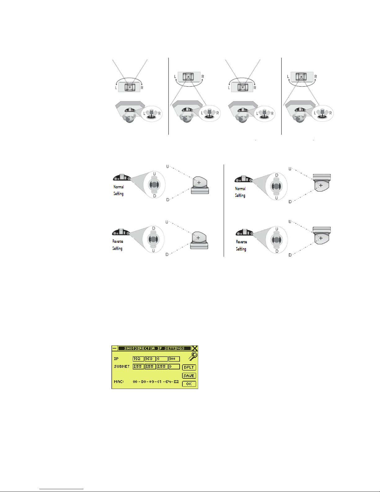
SHOT Director IP Settings Dialog Box
The SHOTDIRECTOR IP SETTINGS dialog box (Figure 24) is used to set/change
the SHOT Director IP and/or subnet addresses. To access it, press the
button, select
It enables a user to:
SHOTDIRECTOR SETTINGS, then select SHOTDIRECTOR IP ADDRESS.
8493_10_r0
Reverse Setting
Normal Setting
camera mounting
Inverted
8493_11_r0
Setup
Figure 24. SHOT Director IP Settings Dialog Box
IP:
SUBNET:
34 Ignite JSC-2300 SHOT Director Robotics/Camera Controller Instruction Manual
8493_sc22_r0
Set the SHOT Director IP address
Set the subnet mask
Page 35

Dialog Boxes
MAC:
DFLT:
View the MAC (Media Access Control) address
Reset the IP address to 192.168.0.100 and the subnet mask
to 255.255.255.0 defaults
SAVE:
OK:
Save IP address and SUBNET mask changes
Close the SHOTDIRECTOR IP SETTINGS dialog box
Select Default Settings Dialog Box
The SELECT DEFAULT SETTINGS dialog box (Figure 25) is used to set/change
selected SHOT Director operating characteristics to factory default values.
To access it, press the
SET DEFAULT. It enables a user to:
Figure 25. Select Default Settings Dialog Box
Setup button, select SHOTDIRECTOR SETTINGS, then select
PAN DIRECTION:
TILT DIRECTION:
SD IP ADDRESS:
BEEP:
HOT KEYS:
DEL PRESET:
DEFAULT
SELECTED ITEMS:
OK:
8493_sc21_r0
Set selected camera default to normal
Set selected camera default to normal
Set default to 192.168.0.100
Set default to ON, 20
Set default to CAM1 through CAM4
Erase presets for all cameras
Reset selected (checked) items to default
Close the SELECT DEFAULT SETTINGS dialog box
Ignite JSC-2300 SHOT Director Robotics/Camera Controller Instruction Manual 35
Page 36

Section 2 — Functional Description
Diagnostics Dialog Box
The DIAGNOSTICS dialog box (Figure 26) is used diagnose/troubleshoot the
SHOT Director controls (joystick, knobs, and buttons). To access it, press
the
Setup button, then select DIAG. It enables a user to:
Figure 26. Diagnostics Dialog Box
8493_sc13_r0
RAW POT VALUES:
Grid (lower left):
FOCUS:
IRIS:
OK:
Display raw input values to the embedded micro-controller in the joystick. The raw pot values from left to
right are zoom, tilt, pan, zoom speed slider, pan/tilt
speed slider.
1st row: Absolute analog to digital (A/D) conversion
values.
2nd row: Zero values offset from center. If the first 3
values are outside the range of greater than -30 and less
than 30 when the joystick is centered, the joystick
requires calibration (refer to Calibrate Joystick on page 39).
Test the on/off operation of each key on the controller.
Te st FOCUS CONTROL knob raw pot values
Tes t MANUAL IRIS knob raw pot values
Close the DIAGNOSTICS dialog box
36 Ignite JSC-2300 SHOT Director Robotics/Camera Controller Instruction Manual
Page 37

Installation and Setup
Note Refer to Controls and Indicators on page 21 to learn the SHOT Director™
controls and indicators functions before starting this setup procedure.
Note To make selections and enter information, the following procedures use the
joystick as a pointing device (joystick for movement and joystick top button
as a mouse-type left click) and the Camera and Preset keypad. Instead of
using the joystick, the MANUAL IRIS and FOCUS CONTROL knobs can also
be used during setup to select various setup parameters.
Installation and setup consists of:
• Install SHOT Director Controller on page 38
• Unpack on page 38
• Connect to Network on page 38
• Connect Power Supply on page 38
Section 3
• Power On on page 39
• Setup SHOT Director Controller on page 39
• Adjust LCD Dialog Box on page 39
• Calibrate Joystick on page 39
• Set Audible Alarm (Optional) on page 42
• Reassign Camera Quick Select Buttons (Optional) on page 42
• Reset SHOT Director Defaults (Optional) on page 43
• Change Pan/Tilt IP Table Entries (Optional) on page 43
• Setup SDC/HDC Robotic Camera on page 44
• Set Camera ID and IP Address on page 44
• Set Pan and Tilt Orientation on page 46
• Set Pan/Tilt Soft Stops on page 46
• Set Camera Video Characteristics on page 48
Ignite JSC-2300 SHOT Director Robotics/Camera Controller Instruction Manual 37
Page 38

Section 3 — Installation and Setup
Install SHOT Director Controller
Unpack
Check all parts received against the packing list enclosed with your shipment, and examine the equipment for any shipping damage. Immediately
report any missing or damaged items to the carrier and to your Grass
Valley Service Representative (See Contacting Grass Valley on page 4).
Keep all manuals supplied with your equipment. You will need them to
complete the installation procedures.
Connect to Network
Note A 10/100 Base TX auto-sensing Ethernet hub is required to connect a JSC-
2300 SHOT Director controller to multiple Ignite SDC/HDC robotic cameras.
Note All SHOT Director controllers and SDC/HDC cameras are preset to default IP
and subnet addresses at the factory to enable the SHOT Director controller
and one camera to establish communication immediately on the network. In
order to connect a second camera, you must change the IP address of the
first camera before connecting the next, then repeat this process until all
cameras are uniquely addressed.
1. For:
• Multiple camera operation, connect an Ethernet cable between the
10/100 MBIT ETHERNET connector on the rear panel of the SHOT
Director controller and the network hub.
• Single camera operation, connect an Ethernet crossover cable
between the 10/100 MBIT ETHERNET connector on the rear panel
of the SHOT Director controller and the Ethernet connector on the
rear of the Pan/Tilt head.
2. Refer to the Ignite SDC/HDC Robotic Camera Instruction Manual for
installing and connecting a camera to the network.
Connect Power Supply
Using the provided power supply, connect the dc (direct current) plug to
the SHOT Director controller 5 V dc input on the rear panel (Figure 11);
plug the other end into a standard ac wall outlet.
38 Ignite JSC-2300 SHOT Director Robotics/Camera Controller Instruction Manual
Page 39

Setup SHOT Director Controller
Power On
1. Ensure that one camera is connected and powered on. Refer to Connect
to Network on page 38.
Note For more information on powering up other devices on the network, see the
operation manual that came with the device.
2. Press the Power button (Figure 5). The Power indicator illuminates.
Note The first time the JSC-2300 SHOT Director controller powers on, the joystick
calibration dialog box (Figure 27) appears. After this initial calibration, every
time the SHOT Director controller powers on, the CAMERA CONTROL home
dialog box (Figure 13) appears.
• The Grass Valley splash dialog box (Figure 12) appears briefly
and then the
appears.
Center Joystick Then Press Enter dialog box (Figure 27)
Setup SHOT Director Controller
Adjust LCD Dialog Box
• If necessary, adjust the LCD CONTRAST and LCD BACKLIGHT on the rear
panel (Figure 11) of the SHOT Director controller to obtain the best
LCD clarity.
Figure 27. Joystick Calibration Dialog Box 1
8493_sc01_r0
Calibrate Joystick
Note The first time the JSC-2300 SHOT Director controller powers on, the joystick
calibration dialog box (Figure 27) appears. After this initial calibration, every
time the SHOT Director controller powers on, the CAMERA CONTROL home
dialog box (Figure 13) appears.
Ignite JSC-2300 SHOT Director Robotics/Camera Controller Instruction Manual 39
Page 40

Section 3 — Installation and Setup
Note To access joystick calibration at any time after initial calibration, while pow-
1. Ensure that the joystick is in the center position, then press the enter
button (Figure 10). The Zeroing Joystick Please Wait dialog box (Figure 28)
appears for approximately 5 seconds.
CAUTION When Zeroing Joystick Please Wait dialog box appears, Do not touch the
Figure 28. Zeroing Joystick Dialog Box
ering on the SHOT Director controller, press and hold the Setup button
(Figure 8), until the Zeroing Joystick Please Wait dialog box appears.
Joystick. The Zeroing Joystick Please Wait dialog box displays approximately 5 seconds.
8493_sc02_r0
2. When the zero calibration process finishes, the Levels dialog box
(Figure 29) appears.
Figure 29. Levels Dialog Box
8493_03_r0
3. Move the joystick control and the sliders to their extreme positions so
the SHOT Director controller can record minimum and maximum
levels. When finished, press the
JOYSTICK
Figure 30. Joystick Calibration Dialog Box 4
dialog box (Figure 30) appears.
enter button (Figure 10). The CALIBRATE
4. Using the joystick, check that the pointer reaches all four corners of the
screen. If not, repeat the joystick calibration by pressing the
(Figure 10).
40 Ignite JSC-2300 SHOT Director Robotics/Camera Controller Instruction Manual
8493_sc04_r0
enter button
Page 41

Setup SHOT Director Controller
5. Using the joystick, navigate to and then click OK to complete the
calibration. The
6. Check default operation between the SHOT Director controller and the
CAMERA CONTROL Home dialog box (Figure 13) appears.
camera.
a. Press the CAMERA button (Figure 10). The CAMERA Select dialog box
(Figure 31) appears.
Figure 31. Camera Select Dialog Box
8493_sc00_r0
b. Using the joystick, select the CAMERA box, type 16, and then press the
enter button (Figure 10). The CAMERA CONTROL Home dialog box
(Figure 13) now indicates
Pan, Tilt, Zoom, Focus, and Iris values change as the joystick, zoom
Camera 16 in the top right corner and the
control, focus knob, and iris knob are rotated.
Verify Controls
Note Do not attempt to control a robotic camera until proper operation of SHOT
Director controls is verified.
1. Press the Setup button (Figure 8). The MAIN SETUP MENU dialog box
(Figure 15) appears.
2. Select DIAG (Figure 15). The DIAGNOSTICS dialog box (Figure 26) appears
and the
3. Center the joystick, then verify that the first three sets of numbers in the
second row of
AUTO IRIS indicator blinks continuously.
RAW POT VALUES are greater than -30 and less than 30. If
the values are outside this range, perform a manual joystick calibration
(refer to Calibrate Joystick on page 39).
4. Move the ZOOM and PAN/TILT SPEED CONTROL sliders from one end of
travel to the other end of travel. Verify that the fourth and fifth set of
RAW POT VALUES read 0 (±2) to 50 (±2) as the sliders are moved. If the
values are outside this range, perform a manual joystick calibration
(refer to Calibrate Joystick on page 39).
5. Rotate the FOCUS CONTROL knob and verify that it operates smoothly for
several rotations in each direction. Verify that the
display on the
DIAGNOSTICS dialog box changes with the rotation of the
FOCUS numerical
knob.
Ignite JSC-2300 SHOT Director Robotics/Camera Controller Instruction Manual 41
Page 42

Section 3 — Installation and Setup
6. Rotate the MANUAL IRIS knob and verify that it operates smoothly for
several rotations in each direction. Verify that the
display on the
knob.
Note The following step refers to the grid in the lower left corner of the DIAGNOS-
7. Verify that a corresponding box highlights when pressing:
• Each button on the controller (except the Power button)
• The button on top of the joystick
8. Select OK.
Set Audible Alarm (Optional)
Note By default, the audible alarm (BEEP) is set to ON (checked box) with the pitch
IRIS numerical
DIAGNOSTICS dialog box changes with the rotation of the
TICS dialog box.
set to 20 (mid-range).
1. Press the Setup button (Figure 8). The MAIN SETUP MENU dialog box
(Figure 15) appears.
2. Select SHOTDIRECTOR SETTINGS (Figure 15). The SHOT DIRECTOR SETTINGS
dialog box (Figure 21) appears.
3. To turn off the audible alarm, use the joystick to uncheck the BEEP
checkbox (Figure 21).
4. To change the BEEP pitch, use the joystick to select the pitch box
(Figure 21), type in a number from 0 to 40, and press the keypad
button (Figure 10).
5. Select OK.
Reassign Camera Quick Select Buttons (Optional)
Note By default, Camera Quick Select buttons (Figure 8) are set to CAM1 through
CAM4. There are only four Quick Select buttons, so assign them to the four
most frequently used cameras.
1. Press the Home button (Figure 8). The CAMERA CONTROL Home dialog box
(Figure 13) appears.
enter
2. To erase the current camera entry, press and hold any Camera Quick
Select buttons (Figure 8) for three seconds.
42 Ignite JSC-2300 SHOT Director Robotics/Camera Controller Instruction Manual
Page 43

3. Press the CAMERA button (Figure 10). The CAMERA select dialog box
(Figure 31) appears.
4. Using the joystick, select the CAMERA box (Figure 31), type the number
of the camera to assign to the Camera Quick Select button, and then
press the
box (Figure 13) now indicates the selected camera in the top right
corner.
5. Press and hold the Camera Quick Select button (Figure 8) until the
newly assigned camera number appears in the box above the Quick
Select button (Figure 13).
enter button (Figure 10). The CAMERA CONTROL Home dialog
Reset SHOT Director Defaults (Optional)
1. Press the Setup button (Figure 8). The MAIN SETUP MENU dialog box
(Figure 15) appears.
2. Select SHOTDIRECTOR SETTINGS (Figure 15). The SHOT DIRECTOR SETTINGS
dialog box (Figure 21) appears.
Setup SHOT Director Controller
3. Select SET DEFAULT (Figure 21). The SELECT DEFAULT SETTINGS dialog box
(Figure 25) appears.
4. With the joystick, select (check or uncheck) any of the selection boxes
PAN DIRECTION, TILT DIRECTION, SD IP ADDRESS, BEEP, HOT KEYS, or DEL
for
PRESET
.
Change Pan/Tilt IP Table Entries (Optional)
CAUTION Do not change the default CAM:16 IP address. This is the default factory
address assigned to all new SDC/HDC camera Pan/Tilt heads. The initial
network communication required to setup and operate a new camera will not
be possible.
Note Although not recommended, the IP Table can be modified if the default IP
addresses are already assigned to other network devices. Check with your
Network Administrator for assignment of valid IP addresses to use in this
table.
Note If you change the Pan/Tilt IP Address table, the addresses listed in Table 2
will not be valid.
1. Press the Setup button (Figure 8). The MAIN SETUP MENU dialog box
2. Select PAN/TILT SETTINGS (Figure 15). The PAN/TILT SETTINGS dialog box
Ignite JSC-2300 SHOT Director Robotics/Camera Controller Instruction Manual 43
(Figure 15) appears.
(Figure 16) appears.
Page 44

Section 3 — Installation and Setup
3. Select IP ADDRESS TABLE (Figure 16). The PAN/TILT IP TABLE dialog box
(Figure 18) appears.
CAUTION Do not change the default CAM:16 IP address. This is the default factory
Note The currently selected camera and IP address are highlighted in the Pan/Tilt
4. Using the joystick, select the camera ID/IP address to modify. The
selected camera ID/IP address automatically fill the edit address boxes
below the table.
5. Use the joystick to select, then modify the IP address box(s).
Note Repeat Step 4 and Step 5 for each camera ID/IP address that needs modified.
6. Select SAVE to save the changes to the table.
address assigned to all new SDC/HDC camera Pan/Tilt heads. The initial
network communication required to setup and operate a new camera will not
be possible.
IP address table.
Note If necessary, reset the Pan/Tilt IP Address table to factory defaults listed in
Table 2 by selecting
selecting SAVE.
DFLT from the PAN/TILT IP TABLE dialog box, then
Setup SDC/HDC Robotic Camera
Set Camera ID and IP Address
Note Each SDC/HDC camera pan/tilt head is factory pre-configured with the
defaults:
Head IP: 192.168.0.126 Corresponds to camera 16 IP address
Subnet Mask: 255.255.255.0
Controller IP: 192.168.0.100 Corresponds to the SHOT Director controller IP address
If your system consists of multiple cameras, you must change the camera
IP address for the first camera to CAM1, and then each successive camera
added to the network to CAM2, CAM3, etc. using the IP addresses listed in
Tabl e 2.
Note Each camera must be connected to the network and assigned a unique IP
44 Ignite JSC-2300 SHOT Director Robotics/Camera Controller Instruction Manual
address and camera identification number prior to connecting any additional
cameras.
Page 45

Table 2. Camera ID and IP Address
Camera
Number
CAM1
CAM2
CAM3
CAM4
CAM5
CAM6
CAM7
CAM8
CAM9
CAM10
CAM11
CAM12
CAM13
CAM14
CAM15
CAM16
Related IP Address
192.168.0.111
192.168.0.112
192.168.0.113
192.168.0.114
192.168.0.115
192.168.0.116
192.168.0.117
192.168.0.118
192.168.0.119
192.168.0.120
192.168.0.121
192.168.0.122
192.168.0.123
192.168.0.124
192.168.0.125
192.168.0.126 (default)
Setup SDC/HDC Robotic Camera
If your system consists of a single camera, changing the camera IP address
to CAM1 is recommended.
1. Press the Setup button (Figure 8). The MAIN SETUP MENU dialog box
(Figure 15) appears. At the bottom of the dialog box, verify the camera
status is
CAM: 16 - STATUS: ONLINE.
2. From the MAIN SETUP MENU dialog box (Figure 15), select PAN/TILT
SETTINGS
. The PAN/TILT SETTINGS dialog box (Figure 16) appears.
3. From the PAN/TILT SETTINGS dialog box (Figure 16), select PAN/TILT IP
ADDRESS
. The PAN/TILT IP ADDRESS dialog box (Figure 18) appears.
4. Select any of the IP field boxes and change them to the desired camera
ID and IP address shown in Tab le 2 .
Note Ensure SUBNET is set to 255.255.255.0 and CA matches the SHOT Director
default IP address (192.168.0.100)
5. Select SET to send the new IP, SUBNET, and CA addresses to the Pan/Tilt
head.
6. From the CONFIRM dialog box (Figure 32), select YES to save the new IP,
SUBNET, and CA addresses to the Pan/Tilt head.
Ignite JSC-2300 SHOT Director Robotics/Camera Controller Instruction Manual 45
Page 46

Section 3 — Installation and Setup
Figure 32. Confirm Dialog Box
7. Reboot (power down/up) the Pan/Tilt head for the new IP, SUBNET, and
CA addresses to take effect.
8. Press the Home button (Figure 8). The CAMERA CONTROL Home dialog box
(Figure 13) appears.
9. From the keypad, press the CAMERA button. The CAMERA dialog box
(Figure 31) appears.
10. Using the joystick, select the CAMERA box. In the Camera box, type the
number of the camera that was just modified.
11. On the Camera and Preset keypad, press enter. The CAMERA CONTROL
Home dialog box (Figure 13) now indicates
camera modified) in the top right corner.
8493_sc15_r0
Camera # (the number of the
12. Repeat process for each camera (one at a time).
Set Pan and Tilt Orientation
Note The SHOT Director controller pan and/or tilt operation can be reversed, if nec-
essary, to compensate for inverted camera mounting and/or operator location in relation to the camera. Refer to PAN and TILT Orientation on page 33.
1. Press the Setup button (Figure 8). The MAIN SETUP MENU dialog box
(Figure 15) appears.
2. From the MAIN SETUP MENU dialog box (Figure 15), select SHOTDIRECTOR
SETTINGS
3. From the SHOTDIRECTOR SETTINGS dialog box (Figure 21), select (check
the box) for
. The SHOTDIRECTOR SETTINGS dialog box (Figure 21) appears.
REVERSE PAN and/or REVERSE TILT as necessary.
Set Pan/Tilt Soft Stops
Note Pan/Tilt soft stops are camera specific and are stored in the Pan/Tilt head.
Factory defaults are ±178° for both Pan and Tilt.
46 Ignite JSC-2300 SHOT Director Robotics/Camera Controller Instruction Manual
Page 47

Setup SDC/HDC Robotic Camera
Note Pan/Tilt soft stops can be adjusted individually to compensate for mounting
location obstructions or installation of a prompter. Refer to the Ignite SDC/
HDC Robotic Camera Instruction Manual for further details concerning soft
stops settings.
1. Press the Setup button (Figure 8). The MAIN SETUP MENU dialog box
(Figure 15) appears.
2. From the MAIN SETUP MENU dialog box (Figure 15), select PAN/TILT
SETTINGS
3. From the PAN/TILT SETTINGS dialog box (Figure 16), select SOFTSTOPS
SETUP
Note Previously saved User soft stops will display as a checked box. If no User soft
4. Select POINTER to change the joystick to a pointing device.
5. Uncheck the U (up), D (down), L (left), and/or R (right) check box(s) for
. The PAN/TILT SETTINGS dialog box (Figure 16) appears.
. The PAN/TILT SOFTSTOPS dialog box (Figure 17) appears.
stops exist, all boxes will be unchecked.
the softstops being changed.
6. Select JOY to change the joystick to motion device.
7. Using the joystick, pan or tilt the camera to the desired soft stop
position.
In the example below (Figure 33), the up (U) soft stop is selected
(unchecked) to set or change. The Tilt position display shows
Figure 33. Pan/Tilt Soft Stop Example
8. Ensure the Pan or Tilt position display shows the desired direction (U,
D, L, R) of the soft stop being set or changed.
9. When the desired position and direction is displayed in the dialog box,
Tilt(U).23.
check the desired soft stop checkbox to acknowledge the position
coordinates.
10. Repeat Step 5 through Step 9 to change any of the other soft stops, then
Ignite JSC-2300 SHOT Director Robotics/Camera Controller Instruction Manual 47
SAVE to save all checked soft stop positions.
select
Page 48

Section 3 — Installation and Setup
Set Camera Video Characteristics
Note Refer to the Ignite SDC/HDC Robotic Camera Instruction Manual for listings
1. Using the joystick, position the camera to shoot a white object that fills
at least 50% of the studio monitor screen (necessary for Automatic
White Balance adjustment).
2. Press the Menu button (Figure 8). The HD/SD CAMERA dialog box
(Figure 14) appears.
and descriptions of Camera Settings Menu selections.
• To set the Automatic White Balance, select
• To set Automatic Black Balance, select
• To display the Camera Setting Menu on the studio monitor, select
MENU ON/OFF, then select UP or DOWN to navigate to the desired selec-
tion.
• To highlight a selection to change, select
DOWN to change its value.
3. When finished, select MENU ON/OFF.
AWB.
ABB.
ITEM, then select UP or
48 Ignite JSC-2300 SHOT Director Robotics/Camera Controller Instruction Manual
Page 49

Operation
Section 4
Note For a description of SHOT Director™ controls, indicators, and dialog box
functions, refer to Controls and Indicators on page 21.
Note To make selections and enter information, the following procedures use the
Camera and Preset keypad with the joystick as a pointing device and joystick
top button as a mouse-type left click. Instead of using the joystick, the
MANUAL IRIS and FOCUS CONTROL knobs can also be used during setup to
select various setup parameters.
Operation consists of:
• Power On/Off on page 49
• Camera Selection on page 50
• Camera Presets Assignment on page 50
• Recall Camera Presets on page 51
Power On/Off
Power On
• Manual Camera Control on page 51
Note For more information on powering up other devices on the network, see the
operation manual that came with the device.
1. Ensure that one camera is connected and powered on. Refer to Connect
to Network on page 38.
Note The first time the JSC-2300 SHOT Director controller powers on, the joystick
calibration dialog box (Figure 28) appears. After the initial calibration, every
time the SHOT Director controller powers on, the CAMERA CONTROL Home
dialog box (Figure 13) appears. If the Center Joystick calibration dialog box
appears in the following step, refer to Calibrate Joystick on page 39.
Ignite JSC-2300 SHOT Director Robotics/Camera Controller Instruction Manual 49
Page 50

Section 4 — Operation
2. Press the Power button (Figure 5). The Power indicator illuminates.
3. The SHOT Director controller is ready for use.
Power Off
• Press the Power button (Figure 5). The Power indicator extinguishes.
Camera Selection
1. Press CAMERA. The CAMERA Select dialog box (Figure 34) appears.
Figure 34. CAMERA Select Dialog Box
The Grass Valley splash dialog box (Figure 12) appears briefly and then
the
CAMERA CONTROL Home dialog box (Figure 13) appears.
Method 1:
2. Using the joystick and keypad, in the CAMERA box type the camera
number, and then click
camera number in the upper right.
Method 2:
1. Press CAMERA. The CAMERA Select dialog box (Figure 34) appears.
2. Select the CAMERA box.
3. Using the FOCUS CONTROL wheel or AUTO IRIS wheel, rotate the wheel to
select the camera number, and then press
shows the selected camera number in the upper right.
Camera Presets Assignment
1. Select a camera (refer to Camera Selection on page 50).
8493_sc12_r0
OK. The CAMERA dialog box shows the selected
enter. The CAMERA dialog box
2. On the Camera and Preset keypad, press PRESET. The ENTER PRESET
dialog box (Figure 35) appears.
50 Ignite JSC-2300 SHOT Director Robotics/Camera Controller Instruction Manual
Page 51

Recall Camera Presets
Figure 35. Enter Preset Dialog Box
8493_sc00_r0
3. In the PRESET box, type the camera number to preset.
Note In the following step, the 0 (default) setting is equal to the maximum robotics
speed (refer to the respective camera manual).
4. In the SPEED box, type the speed (in seconds) for the change from
current position to the preset position.
5. Click STORE.
Note Each SHOT Director controller can store up to 300 preset positions for each
camera.
6. Repeat Step 1 through Step 5 for each camera preset.
Recall Camera Presets
1. Select a camera (refer to Camera Selection on page 50).
2. On the Camera and Preset keypad, press PRESET. The ENTER PRESET
3. In the PRESET box, type the preset number to recall.
Note In the following step, the preset speed can be over-ridden any time by typing
4. Click RECALL.
Manual Camera Control
dialog box (Figure 35) appears.
a new speed in the SPEED box first.
Focus Control
1. Select a camera (refer to Camera Selection on page 50).
Ignite JSC-2300 SHOT Director Robotics/Camera Controller Instruction Manual 51
Page 52

Section 4 — Operation
2. Rotate the FOCUS CONTRIOL wheel:
Iris Control
1. If the AUTO IRIS indicator is not lit, go to Step 2. If the AUTO IRIS indicator
2. Rotate the MANUAL IRIS wheel:
Pan/Tilt Control
Speed
Note This is a variable speed control. When the PAN/TILT SPEED CONTROL is at
• Counterclockwise for
• Clockwise for far
is lit, press the
• Counterclockwise to
• Clockwise to open
the down limit, the control is off. Moving the control up gradually increases
the PAN/TILT speed.
AUTO IRIS button. The AUTO IRIS indicator extinguishes.
near
close
Direction
• Move the slider:
• Up to increase pan/tilt speed
• Down to decrease pan/tilt speed
Note Joystick control of pan/tilt depends on camera mounting and camera/oper-
ator position. Refer to PAN and TILT Orientation on page 33.
Pan
• Move the joystick left and right for pan movement
Tilt
Note Joystick control of pan/tilt depends on camera mounting and camera/oper-
ator position. Refer to PAN and TILT Orientation on page 33.
• Move the joystick up and down for tilt movement.
52 Ignite JSC-2300 SHOT Director Robotics/Camera Controller Instruction Manual
Page 53

Zoom Control
Speed
View
Manual Camera Control
Note This is a variable speed control. When the ZOOM SPEED CONTROL is at the
down limit, the control is off. Moving the control up gradually increases the
zoom speed.
• Move the slider:
• Up to increase zoom speed
• Down to decrease zoom speed
• Rotate the joystick knob:
• Clockwise for a
• Counterclockwise for a
tight view
wide view
Ignite JSC-2300 SHOT Director Robotics/Camera Controller Instruction Manual 53
Page 54

Section 4 — Operation
54 Ignite JSC-2300 SHOT Director Robotics/Camera Controller Instruction Manual
Page 55

Service
General
Troubleshooting
Section 5
The SHOT Director™ Robotics/Camera Controller contains no user-serviceable parts. Refer any servicing to an authorized Grass Valley reseller or
contact Grass Valley Customer Support directly (See Contacting Grass
Valley on page 4).
Should problems occur with the SHOT Director controller, please refer to
the following troubleshooting matrix (Tab le 3 ). If questions or problems
still exist after troubleshooting, please contact your authorized Grass
Valley reseller or contact Grass Valley Customer Support directly. (See
Contacting Grass Valley on page 4.).
Table 3. Troubleshooting (Problem/Cause/Solution) Matrix
Problem Cause Solution
Power Mains power OFF. Energize Mains power
Power supply not connected to Mains Connect power supply to Mains
Power supply not properly connected
to SHOT Director controller.
Power supply failure Using a voltmeter, check for 5 V dc at
Ensure power supply is properly connected to the SHOT Director controller
5 V dc plug on the rear panel (Refer to
Connect Power Supply on page 38).
the output plug of the power supply. If
5 V dc is not present, replace the
power supply.
Ignite JSC-2300 SHOT Director Robotics/Camera Controller Instruction Manual 55
Page 56

Section 5 — Service
Table 3. Troubleshooting (Problem/Cause/Solution) Matrix
Problem Cause Solution
No or erratic camera control Camera Ensure all devices are powered.
Verify that the camera was properly
selected (Refer to Camera Selection
on page 50).
Access the TCP/IP NETWORK dialog
box and verify camera IP address is
displayed. (Refer to TCP/IP Network
Dialog Box on page 32.) If not verify
correct IP address setup for pan/tilt
head and SHOT Director controller
(Refer to Set Camera ID and IP
Address on page 44).
Verify soft stops are set properly
(Refer to Set Pan/Tilt Soft Stops on
page 46).
Ensure PAN/TILT sliders are not set to
zero (full down position).
In multiple camera systems, select
another camera and verify that it can
be controlled. If selected camera cannot be controlled, troubleshoot SHOT
Director and hub. If selected camera
can be controlled, troubleshoot failed
camera. (Refer to camera manual).
Network hub Ensure all devices are powered.
Use crossover cable between SHOT
Director controller and pan/tilt head to
bypass the hub. If SHOT Director controller does not control the camera,
troubleshoot the SHOT Director controller. If SHOT Director controller
controls the camera, replace the hub.
SHOT Director controller Ensure all devices are powered.
Verify that the SHOT Director controls
operate properly (Refer to Verify Con-
trols on page 41).
56 Ignite JSC-2300 SHOT Director Robotics/Camera Controller Instruction Manual
Page 57

Glossary
A
Aspect
The horizontal and vertical display dimension ratio of a picture; i.e., the width divided
by the height (usually expressed as x:y). The
aspect ratio of a traditional standard definition (SD) television screen is 4:3, or 1.33:1.
High definition (HD) television uses an aspect of 16:9 (5 1/3 to 3), or about 1.78:1.
B
Bit Rate
The number of bits per second passed from
one point to another.
Black
A black video signal generated within the
switcher.
Clip
A threshold level adjustment to which the
keying attribute (luminance, chrominance) is
compared for generating the internal key
control signal. Clip, in conjunction with gain,
sets the switching point between the background and the key fill. Also see Gain.
Component Video
A video signal that keeps color and luminance information separate. RGB; Y, R Y, B Y;
and Y, Cr, Cb are examples of component
video.
Composite Video
An encoded video signal that combines color
information with luminance information.
NTSC, PAL, and D 2 are examples of composite video.
D
C
CCD (Charge-Coupled Device)
An image sensor used in digital photography.
CCFL (Cold-Cathode Fluorescent)
CCFL tubes are used for backlighting an
LCD display.
Chroma
The depth or saturation of color. Chroma,
hue, and luminance make up the three characteristics of television color.
Chroma Gain (chroma, color, saturation)
The gain of an amplifier as it pertains to the
intensity of colors in the active picture.
Ignite Glossary 57
E
Ethernet
A form of high speed data transport between
devices on a network.
F
Field
One scan of an interlaced video image. In interlace systems, two fields are required to
make a complete picture (video frame) because alternate lines are scanned. Also see
Frame
Page 58

Glossary
Frame
One complete scan of a video image. For interlace video, alternate lines are scanned so a
frame containing all the picture information
consists of two fields. Also see Field.
Frame Rate
The number of frames presented per second.
For interlace systems the frame rate is half
the field presentation rate.
G
GPI (General Purpose Input)
GPO (General Purpose Output)
A digital signal interface, used to activate a
device or piece of equipment for limited remote control of a device's functions.
H
IP (Internet Protocol)
A data-oriented protocol used for communicating data across a packet-switched internetwork.
J
Jitter
An undesirable variation in the timing of
transitions in a digital signal.
K
L
LCD
Liquid Crystal Display
LED
HD
High Definition
House Sync
Sync generated within a facility that is used
as a reference for generating and/or timing
other signals.
Hue
The location of a color on the color spectrum
(i.e. red, yellow, green, blue). Chroma, hue,
and luminance make up the three characteristics of television color.
I
Interlace
A system of video scanning where the odd
and even numbered lines of a picture are presented consecutively as two separate interleaved fields. The two fields required to
make a complete picture are called a frame.
Light-Emitting Diode
Luminance
The brightness of the picture or area of the
screen being considered. Chroma, hue, and
luminance make up the three characteristics
of television color.
The color video picture information contains
two components: luminance (brightness and
contrast) and chrominance (hue and saturation).
Lux
A measurement of illumination. The metric
equivalent of foot candle.
58 Ignite Glossary
Page 59

Glossary
M
MAC (Media Access Control)
A unique identifier (address) attached to
most forms of networking equipment. On
broadcast networks such as Ethernet, the
MAC address allows each host to be uniquely identified and allows frames to be marked
for specific hosts.
N
NTSC (National Television System Committee)
U.S. government and industry committee
which defined the 525-line 60 (59.94) interlaced fields per second analog broadcast TV
standard over 50 years ago. (This format is
referred to as NTSC.) Of the 525 scan lines,
480 (give or take a few) contain the picture
and the rest contain synchronizing information, hold the encoded closed caption text,
and provide a time delay to move the electron beam back to the top of the screen.
NTSC is used mainly in North America and
Japan.
ProAv
Professional Audio/Video production.
Q
R
S
Saturation
The degree of purity of a color. Adding white
to a color reduces its degree of saturation.
SD
Standard Definition.
Serial Digital Interface (SDI)
[also Serial Digital Video]
A standard for digital video transmission
over coaxial cable; i.e., passing video data
bits in serial form (one bit after another),
along a single wire. Standard Definition serial digital video (SMPTE 259M) operates at
270 Mbits/sec (2 x 13.5 MHz x 10 bits).
O
P
PAL (Phase Alternate Line)
A 625 line 50 interlaced fields per second analog broadcast standard used in many parts
of the world, primarily Europe, but not the
U.S.A. So named because the chroma sub signal phase is different on each successive scan
line to reduce picture artifacts.
Pixel
A picture element. A pixel is a digital sample
of the luminance and color values of a picture at a single point.
The SDI standard uses data words that are 8
or 10 bits in length. Signals are uncompressed and are self-synchronizing between
the source (transmitter) and destination (receiver). A signal in SDI can contain up to four
independent digital audio signals along with
the video signal.
Serial Interface
An interface which allows the switcher to be
controlled remotely by a computer editor or
other serial controller. Data is passed serially
between the editor and the switcher at selectable baud (transmission) rates.
Ignite Glossary 59
Page 60

Glossary
S/N (Signal to Noise) Ratio
The amount of desired signal as compared to
undesired signal. A way of measuring how
good a picture or a sound will be. The higher
the ratio between the desired type of signal
and the unwanted noise, the better the results.
Source
1) An external device providing video. A
source may provide only one video signal, or
it may provide two signals (key fill and key
cut).
2) The video signal(s) from a source, along
with the source definition information associated with that source. See Source Definition.
Subnet Mask
In the Internet Protocol (IP), a subnet (or subnetwork) is a division of a classful network.
Subnetting allows a single large network to
be broken down into what appear (logically)
to be several smaller ones. A network mask,
also known as a subnet mask, netmask or
address mask, is a bitmask used to tell how
many bits in an octet(s) identify the subnetwork, and how many bits provide room for
host addresses. They are typically used to determine whether to send a packet to the
MAC address of the default gateway (for
packets with destinations outside the subnet)
or of the actual machine (for inside the subnet).
Switcher
A device that accepts inputs from a variety of
video sources and allows the operator to select a particular source to be sent to the
switcher's output(s). Also does transitions
between sources and special effects (video
mixing, wiping, keying, and such).
Sync
(1) General term for a synchronizing signal
or signal component. Digital systems generally employ an analog external timing reference signal (such as color black or tri-level
sync) to synchronize different pieces of
equipment. Within the digital signal itself,
however, synchronizing information is carried by special digital codes inserted at the
beginning and end of each active line.
(2) In analog television systems, sync is the
portion of the video signal which occurs during blanking and is used to synchronize the
operation of cameras, monitors, and other
equipment. Horizontal sync occurs within
the blanking period in each horizontal scanning line, and vertical sync occurs within the
vertical blanking period. A color black signal
is often used for synchronizing different
pieces of analog equipment.
T
Tally
A lighted indication that the associated video source is in use. Tally lights may be in
front of a camera to show that it is the camera
being used at that moment, or they may be
used to light up the pushbuttons of video
switchers.
Terminate, Termination
To complete a circuit by connecting a resistive load to it.
TFT
Thin-film Transistor. Often called “active
matrix” display, this is the brightest, most
viewable kind of LCD flat-panel display. It is
also more expensive than “passive matrix”
screens. In a TFT display, each pixel is actively controlled by one or more transistors.
60 Ignite Glossary
Page 61

TTL (Through-the-Lens)
Term used to describe a type of prompter. A
TTL prompter mounts horizontally in front
of the camera. A glass screen mounted 45°
above the prompter reflects the script so that
the announcer can read the text while looking at the camera behind the screen.
U
V
Video Switcher
See Switcher
W
Glossary
X
Y
Z
Ignite Glossary 61
Page 62

Glossary
62 Ignite Glossary
Page 63

Index
A
About this manual 9
Audible Alarm setting 42
B
Back button 25
Brightness control 24
Index
Diagnostics 36
HD/SD Camera 27
Main Setup Menu 28
Pan/Tilt IP Address 30
Pan/Tilt IP Table 31
Pan/Tilt Settings 29
Pan/Tilt Soft Stops 29
Select Default Settings 35
SHOT Director IP Settings 34
SHOT Director Settings 32
Splash 26
TCP/IP Network 32
documentation online 4
C
Camera
control
Control Home dialog box 26
ID and IP Address setup 44
manual control 51
presets assignment 50
Quick Select buttons 25
recall presets 51
selection 50
specific control 25
video setup 48
Components 18
additional 18
included 18
Connectors
10/100 Mb Ethernet
5 V dc input power 26
EIA/TIA 232 26
EIA/TIA 485 26
Controls and Indicators 21
lens 21
rear panel 26
robotics/camera 22
system 24
22, 25
D
Default reset 43
Diagnostics dialog box 36
Dialog Boxes 26
Camera Control Home 26
26
F
FAQ database 4
Focus 22, 51
frequently asked questions 4
Functional Description 19
SHOT Director 19
and camera 19
and Ignite system 20
G
Grass Valley web site 4
H
HD/SD Camera dialog box 27
Home button 24
I
Installation and Setup 37
Install 38
Network 38
Power Supply 38
Setup 39
Iris control 52
auto 22
manual 22
J
Joystick calibration 39
Ignite JSC-2300 SHOT Director Robotics/Camera Controller Instruction Manual 63
Page 64

Index
L
LCD 24
adjustment 39
brightness 24, 26
contrast 24, 26
Lens control 21
focus 22
iris 22
power 22
M
Main Setup Menu dialog box 28
Manual control
51
Focus
Iris 52
Pan/Tilt 52
Zoom 53
Menu button 24
N
Navigation control 24
Back 25
Camera Quick Select 25
Home 24
Menu 24
Setup 24
Network
connection
38
O
online documentation 4
Operation 49
Camera Presets Assignment 50
Camera selection 50
Manual camera control 51
Power On/Off 49
Recall Camera Presets 51
Other Documentation 9
Overview 17
P
Pan/Tilt
control
23, 52
direction 52
IP Address dialog box 30
IP Lookup Table 32
IP Table dialog box 31
orientation 33, 46
Settings dialog box 29
Soft Stops dialog box 29
Soft Stops setup 46
speed 23, 52
Power
50
Off
On 39, 49
Power button 22
Power Supply connection 38
Preface 9
Presets control 25
Q
Quick Select button reassignment 42
R
Rear panel 26
Connectors
10/100 Mb Ethernet
5 V dc input power 26
EIA/TIA 232 26
EIA/TIA 485 26
Controls
LCD brightness
LCD contrast 26
Robotics/Camera control 22
pan/tilt 23
speed 23
zoom 23
speed 23
26
26
S
Safety
Summary
Terms and Symbols 11
Select Default Settings dialog box 35
Service 55
General 55
Troubleshooting 55
11
64 Ignite JSC-2300 SHOT Director Robotics/Camera Controller Instruction Manual
Page 65

Index
Set
Audible Alarm (Beep)
Camera ID and IP Address 44
Camera Video 48
Controls 41
Defaults 43
Joystick 39
LCD 39
Pan/Tilt IP Table 43
Pan/Tilt Orientation 46
Pan/Tilt Soft Stops 46
Power On 39
Quick Select buttons 42
Setup 44
button 24
SHOT Director
IP Settings dialog box
Settings dialog box 32
software download from web 4
Specifications 18
Splash dialog box 26
Standard Documentation 9
System control 24
camera specific 25
cameras and presets 25
LCD 24
navigation 24
42
34
web site FAQ database 4
web site Grass Valley 4
web site software download 4
Z
Zoom
control
speed 23, 53
view 53
23, 53
T
TCP/IP Network dialog box 32
Troubleshooting 55
Camera control 56
Power 55
Problem/Cause/Solution Matrix (tbl) 55
U
Unpack 38
V
Verify controls 41
W
web site documentation 4
Ignite JSC-2300 SHOT Director Robotics/Camera Controller Instruction Manual 65
Page 66

Index
66 Ignite JSC-2300 SHOT Director Robotics/Camera Controller Instruction Manual
 Loading...