

Page 1

iControl
XML Gateway
for Control of Miranda Modular Interfaces
Functional Highlights
Miranda Technologies
Release 1.0
Date: May 9, 2007
Page 2

Change Record
Issue Date Author Reason for Changes
Draft v. 0.1 May 2,
2007
Draft v. 0.2 May 4,
2007
Initial Release v. 1.0 May 9,
2007
Francois Gourvil Initial version.
Francois Gourvil Minor improvements. Added
recommended system architecture
Francois Gourvil Details added on restrictions of use of
XML for command of particular Densite
models and functions
Page 3

Table of Contents
1. Introduction..................................................................................................................... 4
2. Miranda Densité-Series Modular Interfaces................................................................... 5
2. Miranda Densité-Series Modular Interfaces................................................................... 5
3. Miranda iControl: Monitoring and Control over IP........................................................ 9
4. Recommended System Architecture............................................................................. 10
5. Functional Description of iControl XML Gateway Commands................................... 11
5.1 Using the XML Gateway to Identify the Population of Cards in a System.... 12
5.2 Issuing Status Request and Control Commands on a Specific Card .............. 16
5.3 Parameter Status Updates ............................................................................... 24
APPENDIX « A »............................................................................................................. 25
Page 4

iControl XML Gateway for Control of Miranda Modular Interface Functional Highlights
1. Introduction
The objective of this document is to highlight the functionality available with the
iControl XML Gateway to provide the means to monitor and control Miranda video and
audio modular interface cards. The following topics are covered:
• A brief description of Miranda Densite-Series modular interfaces, probes, frames
and controllers
• A brief description of the iControl suite of products
• The overall architecture of XML control in a non-Miranda environment
• Functions associated with the iControl Directory Service
• Functions associated with sessions with a single device
To help describe the functionality accessible via the XML Gateway, examples are
provided by describing similar functions directly in iControl.
Please refer to the following documents for additional information on using the iControl
XML Gateway:
• Programming Reference (API) of the iControl Services Gateway (Document
#226-05M00-200)
Miranda Technologies – Confidential Page 4 of 28
Page 5
iControl XML Gateway for Control of Miranda Modular Interface Functional Highlights
2. Miranda Densité-Series Modular Interfaces
2.1 Summary Description
Miranda offers a wide range of Densité Series modules for Video and Audio infrastructure interfacing and
distribution. The range of cards models is continuously expanding and covers the full breadth of
interfacing and distribution functions, including:
• SDI signal processing (encoder, decoders, D:A)
• SDI frame synchronizer
• Audio A:D / D:A
• HD/SD embedders and de-embedders
• HD downconversion & DA
• Signal measurement over IP
• HD / SDI / analog video DAs
• Digital and analog audio DAs
• Fiber optics (to/from HD/SD)
Multiple formats of signals are supported by various models of cards, including:
• SD-SDI
• HD-SDI
• Analog video
• Digital audio
• Analog audio
Some models of cards also support DVB/ASI and SMPTE 310 Transport Streams. In addition, the Densite
Series includes signal probes, to provide a wide range of telemetry data plus signal alarming functions.
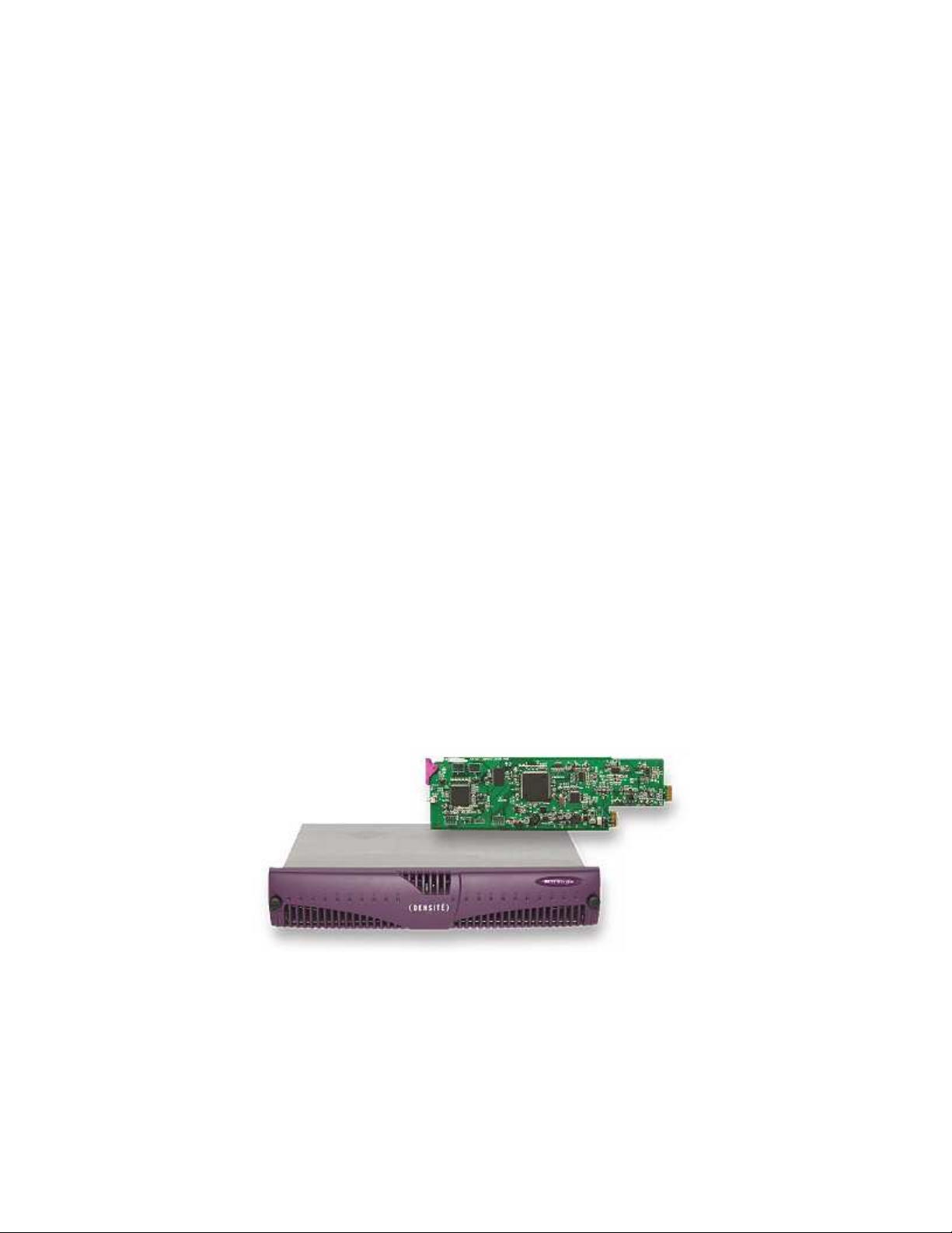
Densite provides space efficiency, with a 2 RU frame that is stackable - with no vertical space lost to
cooling - and that can house up to 20 modules.
Connection to the Densite frame and its respective modules is done via a frame controller module, using
TCP-IP connectivity.
Figure 2.1: Densite frame and module
Miranda Technologies – Confidential Page 5 of 28
Page 6
iControl XML Gateway for Control of Miranda Modular Interface Functional Highlights
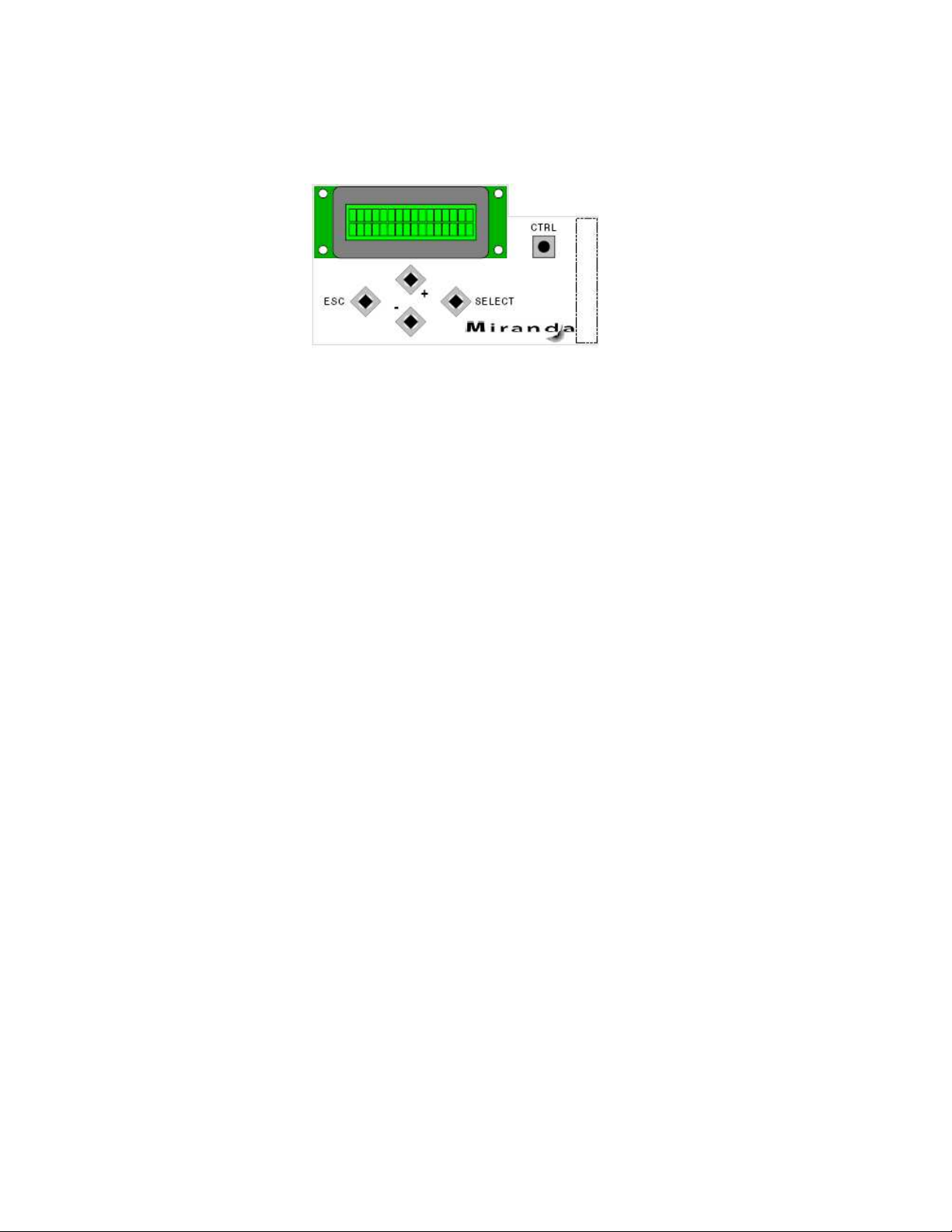
As illustrated below by Figure 2.2, settings on individual Densite card parameters can be performed locally
on each frame using the 16-character LED display and the set of five pushbuttons of the Densite controller
module.
Figure 2.2: Densite Controller
Miranda Technologies – Confidential Page 6 of 28
Page 7

iControl XML Gateway for Control of Miranda Modular Interface Functional Highlights
2.2 Fundamental Densité modules and functions
The Densité-Series product line comprises of over 60 different models of Video and Audio interface cards.
However, the following models could be described as the most fundamental modules:
Conversion and Processing
Model Description
XVP-1801 HD/SD Up/Down/Cross Converter
DAP-1781 8 Channel Digital audio processor
FRS-1101 SDI frame synchronizer/processor/line sync
DEC-1021 12 Bit 3D Composite to SDI Decoder
ENC-1101 SDI to Composite CAV/RGB Encoder
HCO-1821 HD/SD/ASI change over with clean switch
UAP- 1783 8 Channel Universal Audio Processor with optional Dynamic processing and
Up/Down mixing
Embedders and De-embedders
Model Description
AMX-1881 8 HD/SD AES Embedder
ADX-1881 8 HD/SD AES De-Embedder
HD Downconversion and Distribution
Model Description
HDC-1801 HD Downconverter and DA
The use of the XML gateway described in this document provides the ability to perform the great majority
of settings and controls on the cards models listed above.
Miranda Technologies – Confidential Page 7 of 28
Page 8

iControl XML Gateway for Control of Miranda Modular Interface Functional Highlights
2.3 Complementary Densité functions
Some models and functions of the Densité-Series product line are intended for more specialized
applications. They include:
Monitoring and Signal Measurement over IP
Model Description
HCP-1801 HD/SD Control Probe with Embedded Audio
SCP-1121 SDI Control Probe with Embedded Audio
VCP-1021 Composite Control Probe
DCP-1721 Digital Audio Control Probe
ACP-1721 Analog Audio Control Probe (Dual Channel)
Densité Monitoring Features Options
Model Description
-OPT-LS Line Scope Options for DEC, ENC, FRS, HDC, SCP and VCP modules
-OPT-PROBE SDI Control Probe with Embedded Audio
--- Video thumbnails from XVP, FRS, DEC, EAP, ENC, HCO, and HDC modules
--- Audio level meters from UAP
Densité Card Configuration Features
Model Description
--- Card profile copy and paste
The use of the XML gateway described in this document currently does not provide the ability to perform
the majority of settings and controls and monitoring on the cards models and functions listed above.
Miranda Technologies – Confidential Page 8 of 28
Page 9
iControl XML Gateway for Control of Miranda Modular Interface Functional Highlights
3. Miranda iControl: Monitoring and Control over IP
Miranda’s iControl system is a combination of hardware and software products that bring together multiple
advanced features to provide monitoring and control of Miranda and third-party devices. The products
include the iControl Application Server, the RCP-100 Remote Control Panel, iControl Router, for control
of multiple types of routing switchers and iControl Web for the creation of highly customized facility views
and system user interfaces.
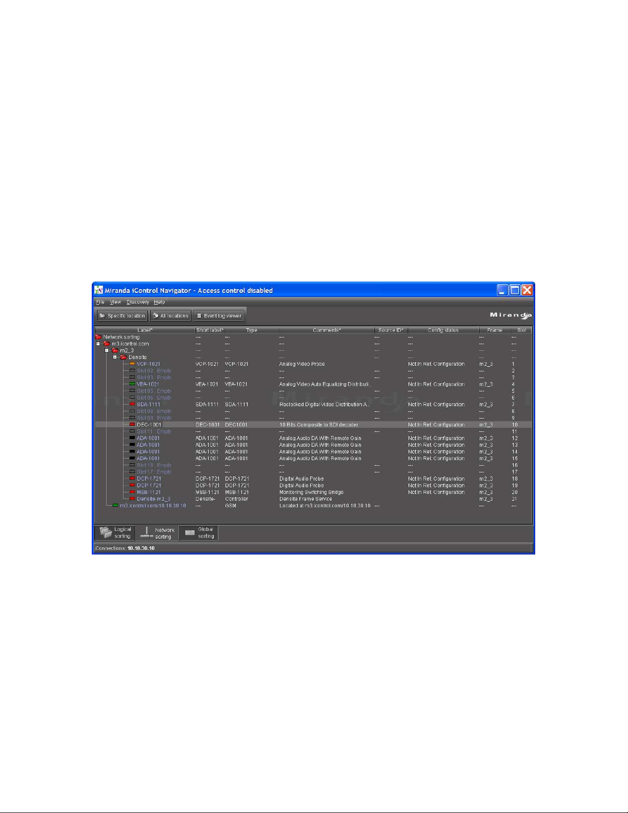
For management of Miranda modular interfaces, the typical environment is iControl Navigator. iControl
Navigator is a graphical user interface used for the set-up and administration, locally or remotely of all
interfaces, based on a tree-like structured hierarchical view of a system, with status information of all
elements. Interfaces can be labeled and grouped to represent their function in a particular topology.
Double clicking on any particular component opens a control panel exposing all parameters and settings for
a given interface module.
Figure 3.1: iControl Navigator
A simple version of iControl called iControl Solo, is also available for management of small quantities of
Densite modules.
Miranda Technologies – Confidential Page 9 of 28
Page 10

iControl XML Gateway for Control of Miranda Modular Interface Functional Highlights
4. Recommended System Architecture
The following software components are required to ensure proper interfacing with Densite-series modular
interface:
• Jini and the Jini Lookup Service
• A library of Densite Services
• The Densite Communicator
• The iControl XML Gateway
Miranda proposes that these components be packaged together to be deployed and run on a PC:
• Jini: Jini is the software technology used by Miranda iControl to manage Densite modules. Via
its lookup mechanisms, Jini ensures plug-and-play functionality, by dynamically recognizing the
addition or removal of modules in a Densite frame, without the need for manual intervention by a
user.
Jini, a Java-based technology, is a service-oriented architecture that defines a programming model
to enable the construction of secure, distributed systems consisting of federations of well-behaved
network services and clients.
• Library of Densite Services: A set of JAR (or Java Archive) files that define the messaging rules
and functions associated to the various models of Densite modules.
• Densite Communicator: The software component that manages communication with the
controller unit of Miranda Densite frames.
• XML Gateway: is the software component that ensures transfer of XML (Extensible Markup
Language) commands and message to and from Densite frames.
The software components can either run on a PC configured for single-user application, or as illustrated by
Figure 4.1, on a PC acting as a central server, allowing control of Densite cards from multiple client PCs.
Figure 4.1: Recommended System Architecture
Miranda Technologies – Confidential Page 10 of 28
Page 11

iControl XML Gateway for Control of Miranda Modular Interface Functional Highlights
5. Functional Description of iControl XML Gateway Commands
For the purpose of describing the type of commands available using the iControl XML Gateway, the
following paragraphs focus on the functions of the Densite DEC-1001, a high-quality composite analog
video to SDI decoder designed for incoming feed applications:
• The DEC-1001 is in slot number 10 of a Densite frame
• The Densite frame has an IP address of 10.10.20.30
• The Densite Manager, running on the iControl Application Server, is where the frame is defined
with the following label: m2_3
• The Application Server has an IP address of 10.10.30.10
• The Application Server App has the hostname: m3.icontrol.com
For communication with the iControl XML Gateway, a free Telnet/Emulator utility called PuTTY was
used.
Figure 5.1: Using PuTTY to connect to the XML Gateway
Two levels of commands are described:
• Using XML to identify and qualify a population of cards
• Using XML to issue status request and control commands on a specific card
Miranda Technologies – Confidential Page 11 of 28
Page 12

iControl XML Gateway for Control of Miranda Modular Interface Functional Highlights
5.1 Using the XML Gateway to Identify the Population of Cards in a System
A specific set of commands is available to define the quantity, type and characteristics of a population of
modules.
• The XML commands described in this section interface with the iControl Directory Services,
using TCP-IP connection through socket port 10001.
To retrieve the entire info on all cards in the system, the listNodes command can be used
Function Command/XML Command XML Gateway Response
Open a telnet
session with the
iControl Directory
Services
Request the list of
devices
telnet 10.10.30.10 10001 ACKTCP
<listNodes/> Returns information on all
devices (nodes) registered to the
Directory Service, and individual
device parameters.
Miranda Technologies – Confidential Page 12 of 28
Page 13

iControl XML Gateway for Control of Miranda Modular Interface Functional Highlights
Figure 5.2: ListNode Command
Miranda Technologies – Confidential Page 13 of 28
Page 14
iControl XML Gateway for Control of Miranda Modular Interface Functional Highlights
As illustrated above in Figure 5.2, the listNode command results in the XML Gateway providing a list of
all devices registered as services in the iControl Directory Service. Among the devices listed is the DEC1001 card, with the following criteria:
Parameter XML Label Value
Card
ID m3.icontrol.com_m2_3_Densite_SLOT_10
Identification
Card Name name DEC1001
Card Group group Proc_Amps
Frame Name frame m2_3
Frame Slot
slot 10
Number
Application
address 10.10.30.10 13000
Server IP address
and socket port
Device Type type DEC1001_46
Jini Lease
expiration 300
Experation
Device Overall
globalStatus OK
Status
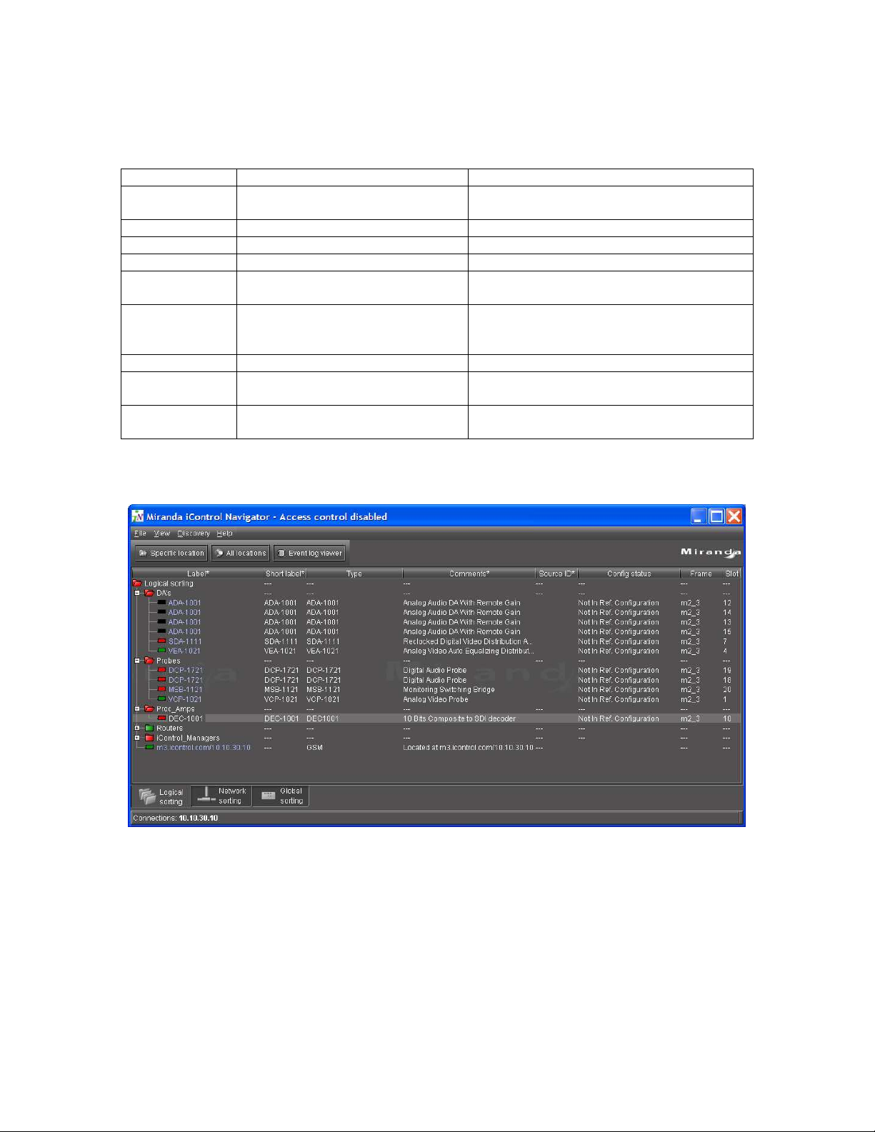
A comparison between Figures 5.2 above and Figure 5.3 below clearly illustrated that some of the same
information provided by iControl Navigator can be extracted with the listNode command.
Figure 5.3: iControl Navigator display of detected Densite modules and other services
Miranda Technologies – Confidential Page 14 of 28
Page 15

iControl XML Gateway for Control of Miranda Modular Interface Functional Highlights
Other Gateway Directory Services commands.
Other Gateway Directory Commands are available, including:
• getGatewayVersion
• nodeCount
• getNode
• getNextNode
Details about these functions and their associated syntax is described in the “Programming Reference
(API) of the iControl Services Gateway” document.
Miranda Technologies – Confidential Page 15 of 28
Page 16

iControl XML Gateway for Control of Miranda Modular Interface Functional Highlights
5.2 Issuing Status Request and Control Commands on a Specific Card
A wide range of commands are available to request status information from a card, as well as to perform
specific control over various card parameter settings. The set of applicable parameters and keys is specific
to each model of card. For the purpose of this document, various functions of the Densite DEC-1001
Composite Analog to SDI Decoder are used to illustrate control and monitoring of Densite cards using the
XML Gateway.
There are various types of settings that can be performed on a DEC-1001 card:
- Setting input formats, operational modes and other functions
- Setting a video processing parameter value to an absolute value
- Performing an audio processing function setting
- Others
Figure 5.4: iControl Panel for DEC-1001 Input Format, Operation Mode and Decoding Filter Settings
XML Gateway commands to control devices include
• openID
• getParameterInfo
• get[ParameterName]
• set[ParameterName]
• closeID
Details about these functions and their associated syntax is described in the “Programming Reference
(API) of the iControl Services Gateway” Document. Details on DEC-1001 and the newer DEC-1002 XML
ParameterName and their associated keys are defined in “Appendix A” of this document.
Miranda Technologies – Confidential Page 16 of 28
Page 17

iControl XML Gateway for Control of Miranda Modular Interface Functional Highlights
5.2.1 Opening a Session
In performing any control and status request on any card, the first step is to establish a communication
session with the card.
• The XML commands described in this section interface with individual Service Nodes, using
TCP-IP connection through socket port 13000.
Function Command/XML Command XML
Gateway
Response
telnet 10.10.30.10 13000 ACKTCP
Open a session
<openID> m3.icontrol.com_m2_3_Densite_SLOT_10</openID> <ack>
with the DEC1001 card in Slot
10 of the Densite
frame
Figure 5.5: Opening a Communication Session with a DEC-1001
Miranda Technologies – Confidential Page 17 of 28
Page 18

iControl XML Gateway for Control of Miranda Modular Interface Functional Highlights
5.2.1 Setting Input Formats on the Card
Two types of functions are illustrated:
• Requesting current status from the DEC-1001 on its Input Format and Video Source Type settings
• Controlling the DEC-1001 to change its Input Format and Video Source Type from one set of
values to another
Function Command/XML Command XML Gateway Response
Request
information on
from the DEC1001 on its Input
Format settings
<getParameterInfo key="vFormatEncoderForced"/> Returns information on
whether the currently
defined Input Format is
“Auto”, “NTSC”, “PAL”,
PALm”, “SECAM”,
“NTSC B&W” or “PAL
B&W”
Request
information on
from the DEC1001 on its
Video Source
<getParameterInfo key="vSourceType"/> Returns information on
whether the currently
defined Video Source
Type is “Satellite”,
“STUDIO” or “VCR”
Type settings
Control the Input
Format setting
on the DEC1001
<setvFormatEncoderForced>set PAL</setvFormatEncoderForced> Retuns an <ack> as well
as confirmation that the
DEC Input Format is set
to “PAL”. Also returns
information on various
video parameters.
Control the
Video Source
Type setting on
the DEC-1001
<setVSourceType>set STUDIO</setVSourceType> Retuns an <ack> as well
as confirmation that the
DEC Video Source Type
is set to “STUDIO”. Also
returns information on
various video parameters.
Miranda Technologies – Confidential Page 18 of 28
Page 19

iControl XML Gateway for Control of Miranda Modular Interface Functional Highlights
Figure 5.6: Requesting Current DEC-1001 Setting for Input Format
Figure 5.7: Requesting Current DEC-1001 Setting for Video Source Type
Miranda Technologies – Confidential Page 19 of 28
Page 20

iControl XML Gateway for Control of Miranda Modular Interface Functional Highlights
Figure 5.8: Controlling the DEC-1001 Setting for Input Format
Figure 5.9: Controlling the DEC-1001 Setting for Video Source Type
Miranda Technologies – Confidential Page 20 of 28
Page 21

iControl XML Gateway for Control of Miranda Modular Interface Functional Highlights
Figure 5.10: iControl Panel for DEC-1001 Reflecting Changes in Input Format and Video Source Type Settings
Miranda Technologies – Confidential Page 21 of 28
Page 22

iControl XML Gateway for Control of Miranda Modular Interface Functional Highlights
5.2.2 Controlling Video Processing Parameters
Two types of functions are illustrated:
• Requesting current status from the DEC-1001 on its video Luminance setting
• Controlling the DEC-1001 to change its Video Luminance setting
Figure 5.11: iControl Panel for DEC-1001 with Original Luminance Level Set for 0
Function Command/XML Command XML Gateway Response
Request
information on
from the DEC1001 on its
Video
Luminance
<getParameterInfo key="vLuma"/> Returns information on
whether the currently set
Luminance level, as well
as valid range,
increments, nominal value
and units.
setting
Control the
Video
Luminance
setting to “300”
on the DEC1001
<setvLuma>set 300</setvLuma> Retuns an <ack> as well
as confirmation that the
DEC Luminance level is
set to “300”. Also
returns information on
new value on “Video All
Gain”
Miranda Technologies – Confidential Page 22 of 28
Page 23

iControl XML Gateway for Control of Miranda Modular Interface Functional Highlights
Figure 5.12: DEC-1001 Luminance Level Request and Setting Commands
Figure 5.13: iControl Panel for DEC-1001 Reflecting Changes in Luminance Level Settings
Miranda Technologies – Confidential Page 23 of 28
Page 24

iControl XML Gateway for Control of Miranda Modular Interface Functional Highlights
5.3 Parameter Status Updates
In situations where changes are made to the card settings via another interface, the XML Gateway provides
continuous updates on various parameter values and settings.
For example, if changes are performed to video luminance levels using the Densite controller illustrated in
Figure 2.2 of this document, the XML connection will result in updates being provided listing new
parameter values. Figure 5.14 illustrates new luminance values being reported by the XML interface.
Figure 5.14: Updates to Luminance Values Settings after Control via Another Interface
Miranda Technologies – Confidential Page 24 of 28
Page 25

APPENDIX « A »
Detailed Key Description
for XML Control of the
Densite DEC-1001 and new DEC-1002
Composite Analog Video to SDI Decoder
Miranda Technologies – Confidential Page 25 of 28
Page 26

<?xml version="1.0" encoding="UTF-8" ?>
- <CARD_PAREMETERS>
<CARD_INFO MODEL="DEC1002" FW="1.0.0" />
- <TAB NAME="Input">
<PARAM NAME="Input Format" KEY="vFormatEncoderForced" ACCESS="R/W" />
<PARAM NAME="Operation Mode" KEY="vSourceType" ACCESS="R/W" />
<PARAM NAME="Decoding Filter" KEY="vDecodingFilter" ACCESS="R/W" />
</TAB>
- <TAB NAME="Video Processing">
<PARAM NAME="All Gain" KEY="vAllGain" ACCESS="R/W" />
<PARAM NAME="Luminance" KEY="vLuma" ACCESS="R/W" />
<PARAM NAME="Chrominance" KEY="vChroma" ACCESS="R/W" />
<PARAM NAME="Hue" KEY="vHue" ACCESS="R/W" />
<PARAM NAME="Black Level" KEY="vSetup" ACCESS="R/W" />
<PARAM NAME="Pedestal" KEY="vPedestal" ACCESS="R/W" />
</TAB>
- <TAB NAME="Audio Output">
- <SUB_TAB_1 NAME="CH 1-2">
<PARAM NAME="CH1 Operation Mode" KEY="aOpModeCH1" ACCESS="R/W" />
<PARAM NAME="CH1 SUM(A+B) Level" KEY="aLvlSumCh1" ACCESS="R/W" />
<PARAM NAME="CH1 Mute" KEY="aMuteMixCh1" ACCESS="R/W" />
<PARAM NAME="CH1 Src A ABUS Select" KEY="aBusSelSrcACH1" ACCESS="R/W" />
<PARAM NAME="CH1 Src A Channel" KEY="aChSelSrcACH1" ACCESS="R/W" />
<PARAM NAME="CH1 Src A Level" KEY="aLvlSrcACH1" ACCESS="R/W" />
<PARAM NAME="CH1 Src B ABUS Select" KEY="aBusSelSrcBCH1" ACCESS="R/W" />
<PARAM NAME="CH1 Src B Channel" KEY="aChSelSrcBCH1" ACCESS="R/W" />
<PARAM NAME="CH1 Src B Level" KEY="aLvlSrcBCH1" ACCESS="R/W" />
<PARAM NAME="CH2 Operation Mode" KEY="aOpModeCH2" ACCESS="R/W" />
<PARAM NAME="CH2 SUM(A+B) Level" KEY="aLvlSumCh2" ACCESS="R/W" />
<PARAM NAME="CH2 Mute" KEY="aMuteMixCh2" ACCESS="R/W" />
<PARAM NAME="CH2 Src A ABUS Select" KEY="aBusSelSrcACH2" ACCESS="R/W" />
<PARAM NAME="CH2 Src A Channel" KEY="aChSelSrcACH2" ACCESS="R/W" />
<PARAM NAME="CH2 Src A Level" KEY="aLvlSrcACH2" ACCESS="R/W" />
<PARAM NAME="CH2 Src B ABUS Select" KEY="aBusSelSrcBCH2" ACCESS="R/W" />
<PARAM NAME="CH2 Src B Channel" KEY="aChSelSrcBCH2" ACCESS="R/W" />
<PARAM NAME="CH2 Src B Level" KEY="aLvlSrcBCH2" ACCESS="R/W" />
</SUB_TAB_1>
- <SUB_TAB_1 NAME="CH 3-4">
<PARAM NAME="CH3 Operation Mode" KEY="aOpModeCH3" ACCESS="R/W" />
<PARAM NAME="CH3 SUM(A+B) Level" KEY="aLvlSumCh3" ACCESS="R/W" />
<PARAM NAME="CH3 Mute" KEY="aMuteMixCh3" ACCESS="R/W" />
<PARAM NAME="CH3 Src A ABUS Select" KEY="aBusSelSrcACH3" ACCESS="R/W" />
<PARAM NAME="CH3 Src A Channel" KEY="aChSelSrcACH3" ACCESS="R/W" />
<PARAM NAME="CH3 Src A Level" KEY="aLvlSrcACH3" ACCESS="R/W" />
<PARAM NAME="CH3 Src B ABUS Select" KEY="aBusSelSrcBCH3" ACCESS="R/W" />
<PARAM NAME="CH3 Src B Channel" KEY="aChSelSrcBCH3" ACCESS="R/W" />
<PARAM NAME="CH3 Src B Level" KEY="aLvlSrcBCH3" ACCESS="R/W" />
<PARAM NAME="CH4 Operation Mode" KEY="aOpModeCH4" ACCESS="R/W" />
<PARAM NAME="CH4 SUM(A+B) Level" KEY="aLvlSumCh4" ACCESS="R/W" />
<PARAM NAME="CH4 Mute" KEY="aMuteMixCh4" ACCESS="R/W" />
<PARAM NAME="CH4 Src A ABUS Select" KEY="aBusSelSrcACH4" ACCESS="R/W" />
<PARAM NAME="CH4 Src A Channel" KEY="aChSelSrcACH4" ACCESS="R/W" />
<PARAM NAME="CH4 Src A Level" KEY="aLvlSrcACH4" ACCESS="R/W" />
<PARAM NAME="CH4 Src B ABUS Select" KEY="aBusSelSrcBCH4" ACCESS="R/W" />
<PARAM NAME="CH4 Src B Channel" KEY="aChSelSrcBCH4" ACCESS="R/W" />
<PARAM NAME="CH4 Src B Level" KEY="aLvlSrcBCH4" ACCESS="R/W" />
Miranda Technologies – Confidential Page 26 of 28
Page 27

</SUB_TAB_1>
- <SUB_TAB_1 NAME="CH 5-6">
<PARAM NAME="CH5 Operation Mode" KEY="aOpModeCH5" ACCESS="R/W" />
<PARAM NAME="CH5 SUM(A+B) Level" KEY="aLvlSumCh5" ACCESS="R/W" />
<PARAM NAME="CH5 Mute" KEY="aMuteMixCh5" ACCESS="R/W" />
<PARAM NAME="CH5 Src A ABUS Select" KEY="aBusSelSrcACH5" ACCESS="R/W" />
<PARAM NAME="CH5 Src A Channel" KEY="aChSelSrcACH5" ACCESS="R/W" />
<PARAM NAME="CH5 Src A Level" KEY="aLvlSrcACH5" ACCESS="R/W" />
<PARAM NAME="CH5 Src B ABUS Select" KEY="aBusSelSrcBCH5" ACCESS="R/W" />
<PARAM NAME="CH5 Src B Channel" KEY="aChSelSrcBCH5" ACCESS="R/W" />
<PARAM NAME="CH5 Src B Level" KEY="aLvlSrcBCH5" ACCESS="R/W" />
<PARAM NAME="CH6 Operation Mode" KEY="aOpModeCH6" ACCESS="R/W" />
<PARAM NAME="CH6 SUM(A+B) Level" KEY="aLvlSumCh6" ACCESS="R/W" />
<PARAM NAME="CH6 Mute" KEY="aMuteMixCh6" ACCESS="R/W" />
<PARAM NAME="CH6 Src A ABUS Select" KEY="aBusSelSrcACH6" ACCESS="R/W" />
<PARAM NAME="CH6 Src A Channel" KEY="aChSelSrcACH6" ACCESS="R/W" />
<PARAM NAME="CH6 Src A Level" KEY="aLvlSrcACH6" ACCESS="R/W" />
<PARAM NAME="CH6 Src B ABUS Select" KEY="aBusSelSrcBCH6" ACCESS="R/W" />
<PARAM NAME="CH6 Src B Channel" KEY="aChSelSrcBCH6" ACCESS="R/W" />
<PARAM NAME="CH6 Src B Level" KEY="aLvlSrcBCH6" ACCESS="R/W" />
</SUB_TAB_1>
- <SUB_TAB_1 NAME="CH 7-8">
<PARAM NAME="CH7 Operation Mode" KEY="aOpModeCH7" ACCESS="R/W" />
<PARAM NAME="CH7 SUM(A+B) Level" KEY="aLvlSumCh7" ACCESS="R/W" />
<PARAM NAME="CH7 Mute" KEY="aMuteMixCh7" ACCESS="R/W" />
<PARAM NAME="CH7 Src A ABUS Select" KEY="aBusSelSrcACH7" ACCESS="R/W" />
<PARAM NAME="CH7 Src A Channel" KEY="aChSelSrcACH7" ACCESS="R/W" />
<PARAM NAME="CH7 Src A Level" KEY="aLvlSrcACH7" ACCESS="R/W" />
<PARAM NAME="CH7 Src B ABUS Select" KEY="aBusSelSrcBCH7" ACCESS="R/W" />
<PARAM NAME="CH7 Src B Channel" KEY="aChSelSrcBCH7" ACCESS="R/W" />
<PARAM NAME="CH7 Src B Level" KEY="aLvlSrcBCH7" ACCESS="R/W" />
<PARAM NAME="CH8 Operation Mode" KEY="aOpModeCH8" ACCESS="R/W" />
<PARAM NAME="CH8 SUM(A+B) Level" KEY="aLvlSumCh8" ACCESS="R/W" />
<PARAM NAME="CH8 Mute" KEY="aMuteMixCh8" ACCESS="R/W" />
<PARAM NAME="CH8 Src A ABUS Select" KEY="aBusSelSrcACH8" ACCESS="R/W" />
<PARAM NAME="CH8 Src A Channel" KEY="aChSelSrcACH8" ACCESS="R/W" />
<PARAM NAME="CH8 Src A Level" KEY="aLvlSrcACH8" ACCESS="R/W" />
<PARAM NAME="CH8 Src B ABUS Select" KEY="aBusSelSrcBCH8" ACCESS="R/W" />
<PARAM NAME="CH8 Src B Channel" KEY="aChSelSrcBCH8" ACCESS="R/W" />
<PARAM NAME="CH8 Src B Level" KEY="aLvlSrcBCH8" ACCESS="R/W" />
</SUB_TAB_1>
- <SUB_TAB_1 NAME="Embedding">
<PARAM NAME="AES 1-2 Group" KEY="aGrpToMux1" ACCESS="R/W" />
<PARAM NAME="AES 3-4 Group" KEY="aGrpToMux2" ACCESS="R/W" />
</SUB_TAB_1>
</TAB>
- <TAB NAME="Blanking">
<PARAM NAME="VBI" KEY="vVBlankMode" ACCESS="R/W" />
<PARAM NAME="Extended VBI" KEY="vWSSModeOut" ACCESS="R/W" />
</TAB>
- <TAB NAME="Timing">
<PARAM NAME="Vertical" KEY="vVTiming" ACCESS="R/W" />
<PARAM NAME="Horizontal" KEY="vHTiming" ACCESS="R/W" />
<PARAM NAME="Frame Delay" KEY="vFrameDelayTiming" ACCESS="R/W" />
</TAB>
- <TAB NAME="Reference Input">
Miranda Technologies – Confidential Page 27 of 28
Page 28

<PARAM NAME="Reference Source" KEY="avRefOrigin" ACCESS="R/W" />
<PARAM NAME="URS Format" KEY="dUrsType" ACCESS="R/W" />
</TAB>
- <TAB NAME="Input Error">
<PARAM NAME="Input Error" KEY="vFrzType" ACCESS="R/W" />
</TAB>
- <TAB NAME="Test">
<PARAM NAME="Video" KEY="vTest" ACCESS="R/W" />
<PARAM NAME="Audio Test CH 1-2" KEY="aTestAES1" ACCESS="R/W" />
<PARAM NAME="Audio Test CH 3-4" KEY="aTestAES2" ACCESS="R/W" />
<PARAM NAME="Audio Test CH 5-6" KEY="aTestAES3" ACCESS="R/W" />
<PARAM NAME="Audio Test CH 7-8" KEY="aTestAES4" ACCESS="R/W" />
</TAB>
- <TAB NAME="ABUS">
<PARAM NAME="Mutliple Card Config" KEY="dCardSystemConfig" ACCESS="R/W" />
</TAB>
</CARD_PAREMETERS>
Miranda Technologies – Confidential Page 28 of 28
 Loading...