

Page 1
User Guide
Version 6.00
M786-1600-328
11 March 2014
Page 2

1
Copyright and Trademark Notice
Copyright © 2001-2014, Miranda Technologies Partnership.
Belden, Belden Sending All The Right Signals, and the Belden logo are trademarks or registered trademarks of Belden Inc. or its affiliated companies in the United States and other jurisdictions. Miranda, iControl, Kaleido-X, Kaleido-K2, Kaleido-Alto, NVision, and Densité are
trademarks or registered trademarks of Miranda Technologies Partnership. All rights reserved.
Belden Inc., Miranda Technologies Partnership and other parties may also have trademark
rights in other terms used herein.
Warranty Policies
Warranty information is available in the Support section of the Miranda Web site
(www.miranda.com).
Title iControl Solo Version 6.00 User Guide
Part Number M786-1600-328
Revision Date 11 March 2014 11:22 am
ii
Page 3

Table of Contents
1 Introduction . . . . . . . . . . . . . . . . . . . . . . . . . . . . . . . . . . . . . . . . . . . . 1
Overview . . . . . . . . . . . . . . . . . . . . . . . . . . . . . . . . . . . . . . . . . . . . . . . . . . . . . . . . . . . . . . . . . . . . . . . . . . 1
Differences Between iControl Solo and the Standard iControl System . . . . . . . . . . . . . . . .1
2 Getting Started with iControl Solo . . . . . . . . . . . . . . . . . . . . . . . 3
Key Concepts . . . . . . . . . . . . . . . . . . . . . . . . . . . . . . . . . . . . . . . . . . . . . . . . . . . . . . . . . . . . . . . . . . . . . .3
Communicators . . . . . . . . . . . . . . . . . . . . . . . . . . . . . . . . . . . . . . . . . . . . . . . . . . . . . . . . . . . . . . . 3
Densité Manager . . . . . . . . . . . . . . . . . . . . . . . . . . . . . . . . . . . . . . . . . . . . . . . . . . . . . . . . . . . . . . 3
License Management . . . . . . . . . . . . . . . . . . . . . . . . . . . . . . . . . . . . . . . . . . . . . . . . . . . . . . . . . . 3
Detailed Directions . . . . . . . . . . . . . . . . . . . . . . . . . . . . . . . . . . . . . . . . . . . . . . . . . . . . . . . . . . . . . . . .4
Connecting Densité and Imaging Series Housing Frames . . . . . . . . . . . . . . . . . . . . . . . 4
Adding Densité Communicator Services . . . . . . . . . . . . . . . . . . . . . . . . . . . . . . . . . . . . . . . 5
Adding Kaleido-Solo Services . . . . . . . . . . . . . . . . . . . . . . . . . . . . . . . . . . . . . . . . . . . . . . . . . . 6
Configuring Imaging Communicator Services . . . . . . . . . . . . . . . . . . . . . . . . . . . . . . . . . . 7
Licensing Options . . . . . . . . . . . . . . . . . . . . . . . . . . . . . . . . . . . . . . . . . . . . . . . . . . . . . . . . . . . . . 9
3 Using iControl Solo . . . . . . . . . . . . . . . . . . . . . . . . . . . . . . . . . . . . 17
Key Concepts . . . . . . . . . . . . . . . . . . . . . . . . . . . . . . . . . . . . . . . . . . . . . . . . . . . . . . . . . . . . . . . . . . . . 17
iControl Solo Window . . . . . . . . . . . . . . . . . . . . . . . . . . . . . . . . . . . . . . . . . . . . . . . . . . . . . . . . 17
Control Panels and Device Parameters . . . . . . . . . . . . . . . . . . . . . . . . . . . . . . . . . . . . . . . . 18
Control Panel Tabs . . . . . . . . . . . . . . . . . . . . . . . . . . . . . . . . . . . . . . . . . . . . . . . . . . . . . . . . . . . 19
Info Control Panels . . . . . . . . . . . . . . . . . . . . . . . . . . . . . . . . . . . . . . . . . . . . . . . . . . . . . . . . . . . 19
Devices Groups . . . . . . . . . . . . . . . . . . . . . . . . . . . . . . . . . . . . . . . . . . . . . . . . . . . . . . . . . . . . . . 20
Views . . . . . . . . . . . . . . . . . . . . . . . . . . . . . . . . . . . . . . . . . . . . . . . . . . . . . . . . . . . . . . . . . . . . . . . . 21
Alarm Status . . . . . . . . . . . . . . . . . . . . . . . . . . . . . . . . . . . . . . . . . . . . . . . . . . . . . . . . . . . . . . . . . 22
Reference Configuration . . . . . . . . . . . . . . . . . . . . . . . . . . . . . . . . . . . . . . . . . . . . . . . . . . . . . . 22
Loudness Logging and Analyzing . . . . . . . . . . . . . . . . . . . . . . . . . . . . . . . . . . . . . . . . . . . . . 23
Densité Upgrade Manager . . . . . . . . . . . . . . . . . . . . . . . . . . . . . . . . . . . . . . . . . . . . . . . . . . . . 28
Detailed Directions . . . . . . . . . . . . . . . . . . . . . . . . . . . . . . . . . . . . . . . . . . . . . . . . . . . . . . . . . . . . . . 31
Opening iControl Solo . . . . . . . . . . . . . . . . . . . . . . . . . . . . . . . . . . . . . . . . . . . . . . . . . . . . . . . . 31
Closing iControl Solo . . . . . . . . . . . . . . . . . . . . . . . . . . . . . . . . . . . . . . . . . . . . . . . . . . . . . . . . . 31
Opening Control Panels . . . . . . . . . . . . . . . . . . . . . . . . . . . . . . . . . . . . . . . . . . . . . . . . . . . . . . 31
Opening Info Control Panels . . . . . . . . . . . . . . . . . . . . . . . . . . . . . . . . . . . . . . . . . . . . . . . . . . 32
Changing Device Information . . . . . . . . . . . . . . . . . . . . . . . . . . . . . . . . . . . . . . . . . . . . . . . . . 32
Managing Device Groups . . . . . . . . . . . . . . . . . . . . . . . . . . . . . . . . . . . . . . . . . . . . . . . . . . . . .32
Adding Cards to the Reference Configuration . . . . . . . . . . . . . . . . . . . . . . . . . . . . . . . . . 33
1
Page 4

toc
Removing Cards from the Reference Configuration . . . . . . . . . . . . . . . . . . . . . . . . . . . . 34
Working with Loudness Logger and Loudness Analyzer . . . . . . . . . . . . . . . . . . . . . . . 34
Working with Densité Upgrade Manager . . . . . . . . . . . . . . . . . . . . . . . . . . . . . . . . . . . . . . 51
Installing IC-USB . . . . . . . . . . . . . . . . . . . . . . . . . . . . . . . . . . . . . . . . . 63
Key Concepts . . . . . . . . . . . . . . . . . . . . . . . . . . . . . . . . . . . . . . . . . . . . . . . . . . . . . . . . . . . . . . . . . . . . 63
IC-USB . . . . . . . . . . . . . . . . . . . . . . . . . . . . . . . . . . . . . . . . . . . . . . . . . . . . . . . . . . . . . . . . . . . . . . . 63
IC-USB Driver . . . . . . . . . . . . . . . . . . . . . . . . . . . . . . . . . . . . . . . . . . . . . . . . . . . . . . . . . . . . . . . . . 63
Detailed Directions . . . . . . . . . . . . . . . . . . . . . . . . . . . . . . . . . . . . . . . . . . . . . . . . . . . . . . . . . . . . . . 63
Connecting the IC-USB Device to a PC or Laptop . . . . . . . . . . . . . . . . . . . . . . . . . . . . . . 63
Connecting the IC-USB Device to a Miranda Quartet 2 Frame . . . . . . . . . . . . . . . . . . 63
Connecting the IC-USB Device to a Miranda Symphonie Frame . . . . . . . . . . . . . . . . 64
Determining the IC-USB COM Port Number . . . . . . . . . . . . . . . . . . . . . . . . . . . . . . . . . . . 64
Installing a Single Imaging Frame . . . . . . . . . . . . . . . . . . . . . . . . . . . . . . . . . . . . . . . . . . . . . 64
Installing Multiple Imaging Frames . . . . . . . . . . . . . . . . . . . . . . . . . . . . . . . . . . . . . . . . . . . 64
Contact Us. . . . . . . . . . . . . . . . . . . . . . . . . . . . . . . . . . . . . . . . . . . . . . . . 65
2
Page 5

Overview
This guide describes how to configure and use iControl Solo for controlling and monitoring
devices required in the broadcast signal path for interfacing, routing and distribution. iControl
Solo is designed and produced by Miranda.
iControl Solo is a stand-alone, PC-based control application which offers affordable control
directly from a desktop or laptop that has Windows 7™. It provides easy list-based control and
configuration of up to 100 Densité Series and/or Imaging Series modules. Operators are
provided with quick access to devices and parameters for fast and easy control. More
advanced control requirements demanding simultaneous, multi-device monitoring and error
logging, and a customized, highly graphical user interface, can be met with the iControl
Application Server. A USB-to-RS-422 adapter (IC-USB) used to connect Imaging Series housing
frames is sold separately.
In brief, iControl Solo offers the following key features and benefits:
Introduction
• an iControl Solo window with different sorting options, similar to iControl Navigator,
• drivers for most Miranda Densité and Imaging devices,
• the ability to interface up to 100 devices,
• easy problem resolution using status indicators,
•ideal for set and forget operations.
• [OPTIONAL] a loudness logging and analysis service (IC-LOUDNESS-LOG-1-SOLO loudness
logging option for one device to be installed on iControl Solo)
Differences Between iControl Solo and the Standard iControl
System
iControl Solo does not:
•provide thumbnails,
• use a GSM (Global Status Manager) for central management of alarm conditions and error
logging,
• support audio level meters (ALMs),
• support Virtual Service Managers for configuring and controlling Miranda proc amp
devices,
• support Router Manager for configuring and controlling routing switchers.
Page 6

Introduction
Overview
2
Page 7

Getting Started with iControl Solo
Key Concepts
Communicators
Communicators are software components that implement a specific protocol for controlling a
family of devices.
Communicators in iControl Solo are responsible for the discovery process whereby a PC or
laptop detects Miranda devices connected to its serial ports or on the LAN, and initiates
services to control these devices.
A communicator is an application that handles the communications between your PC or
laptop and Densité or Imaging series frames on the network. The two types of communicators
(Imaging and Densité) are configurable services in iControl Solo.
Imaging Communicators allow you to control signal processing and distribution performance
modules housed in Miranda Imaging series (Symphonie, Quartet 2) frames. The Imaging series
frames are connected to your PC or laptop via RS-422 serial ports.
Densité Communicators allow you to control interfacing and distribution modules housed in
Miranda Densité frames. A Densité frame is connected to the network via its Densité
Controller Ethernet port.
To be able to use a communicator, the service must be configured. If the service is not
configured, you will not be able to control the devices even if they are connected. If the service
is configured, but there are no cards connected, only the service will be displayed in
iControl Solo.
Densité Manager
The Densité Manager is a service that allows you to manage multiple Densité frames (using
Densité Communicators).
For the Densité Manager to discover cards and begin controlling services, you need to specify
the IP addresses of the Densité frames that it will manage. Each frame may contain up to 20
devices. If you do not add any addresses, or if you add an incorrect address, the Densité
Manager will not discover any frames.
License Management
License management is the method by which iControl Solo administrators can request,
activate, and distribute licenses for options. The majority of tasks related to license
management have as a starting point the Miranda License Manager page.
Page 8
Getting Started with iControl Solo
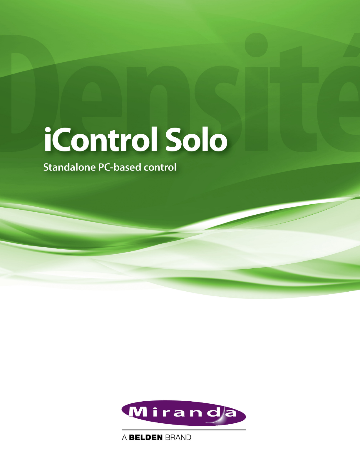
Customer-supplied PC or
laptop that has iControl
Up to 4 daisy-chained Imaging
frames
Up to 100 Densité cards
Detailed Directions
Concept Description
License An agreement to use a specific software module or collection of modules under specific terms
Miranda License
Manager
Software Feature A licensable portion of software.
License request file A file iControl Solo generates that you send to Miranda by e-mail in order to request licenses for
Activation file A file Miranda sends to you that unlocks and activates one or more optional features.
See also
For more information about licensing, see "Licensing Options", on page 9.
Detailed Directions
To set up your iControl Solo system you will need to:
• connect the Densité and Imaging frames that house the cards you wish to control
• connect the Kaleido-Solos you wish to control
• configure Densité and Imaging services in iControl Solo
• configure KSolo services in iControl Solo
Web-based license management for end-users.
one or more optional features.
Connecting Densité and Imaging Series Housing Frames
You can connect your iControl Solo PC to Densité frames and Kaleido-Solos over the network
through an Ethernet router, or directly via a crossover cable. Imaging frames (Symphonie and
Quartet 2) are connected to your PC or laptop using either the IC-USB device, or an RS-232-toRS-422 converter.
Connecting multiple Densité Series frames through a router, and up to 4 Imaging Series frames via IC-USB
4
Page 9
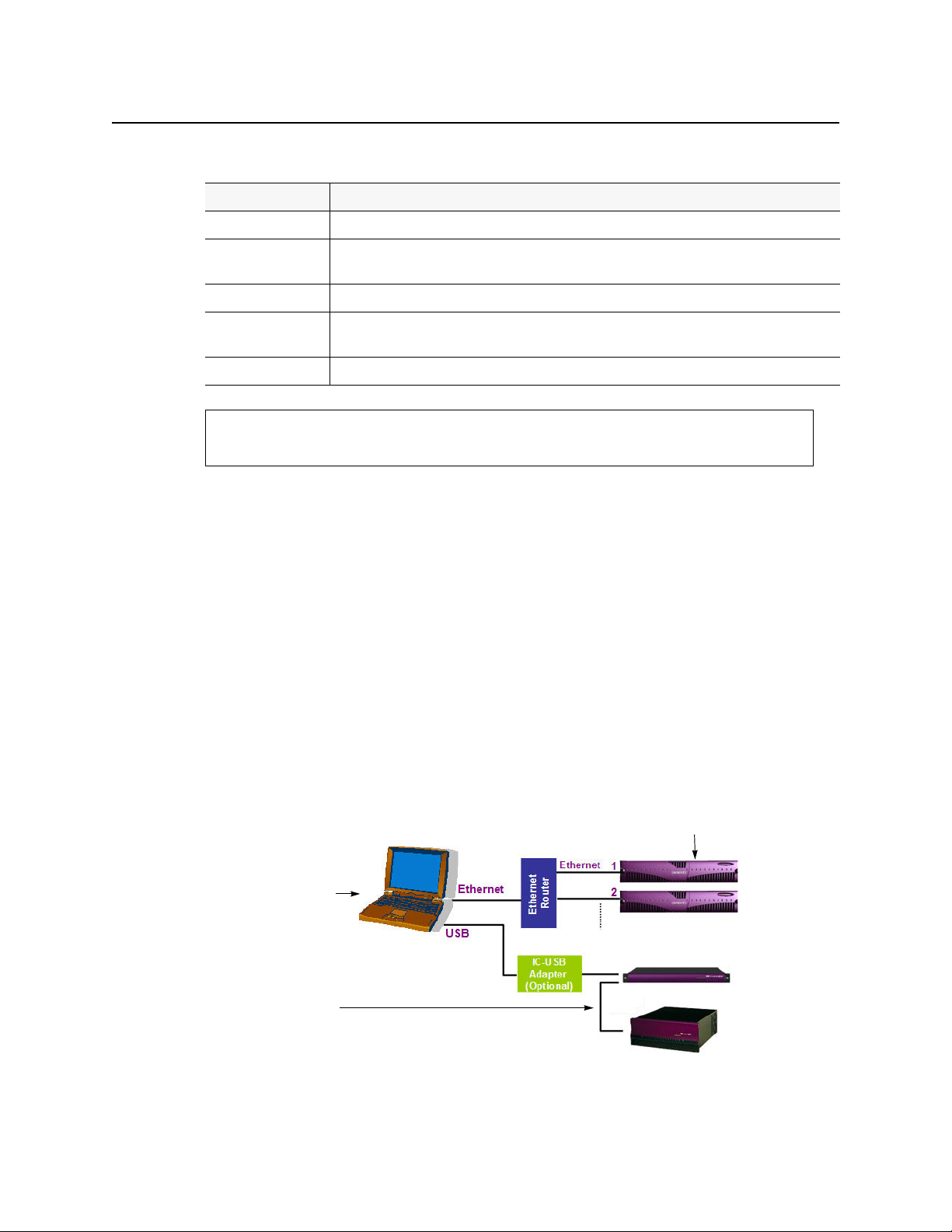
Connecting a single Densité Series frame without a router
Crossover Cable
See also
For more information about the IC-USB device, see "Installing IC-USB", on page 63.
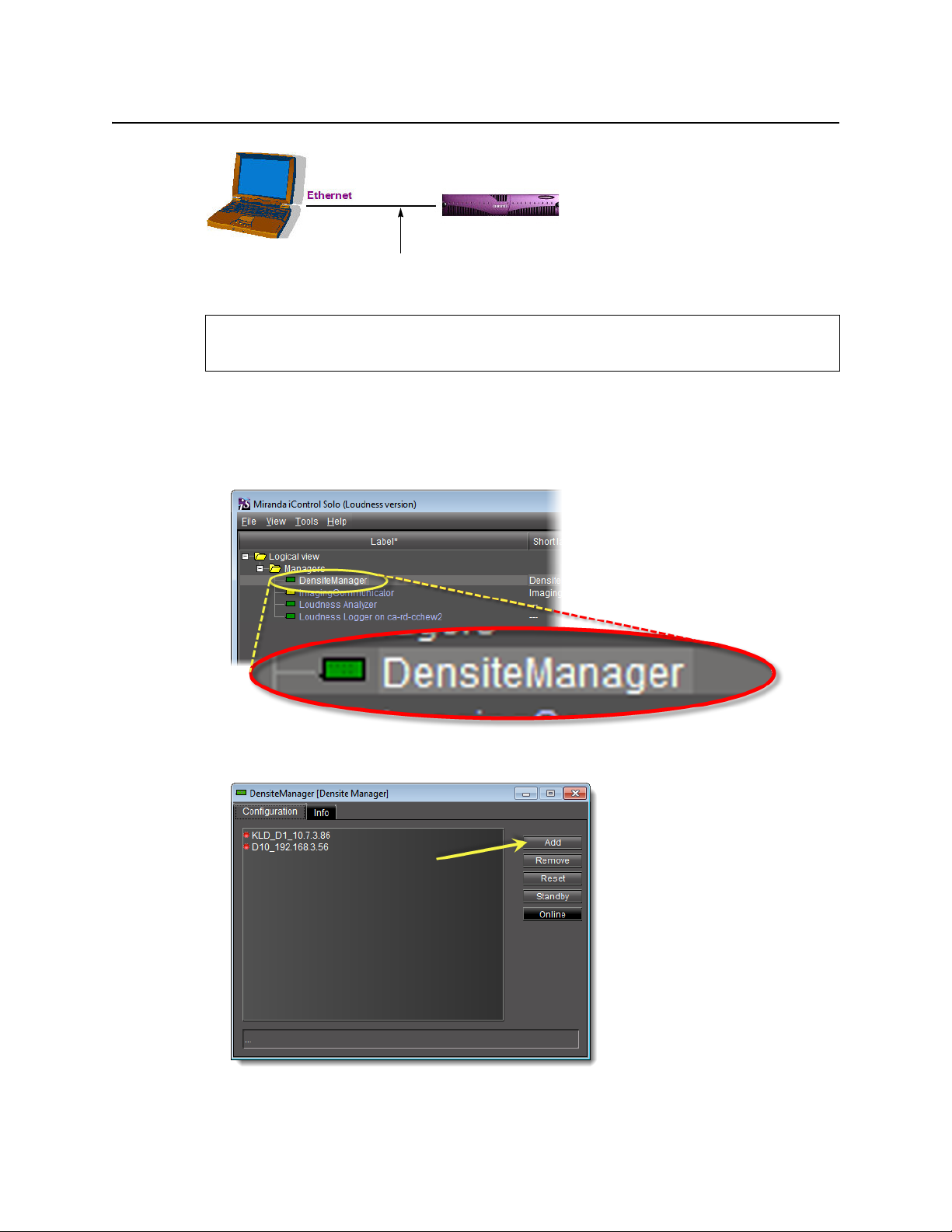
Adding Densité Communicator Services
To add a Densité Communicator service
1. Open iControl, Solo and double-click DensiteManager in the logical view.
iControl Solo
User Guide
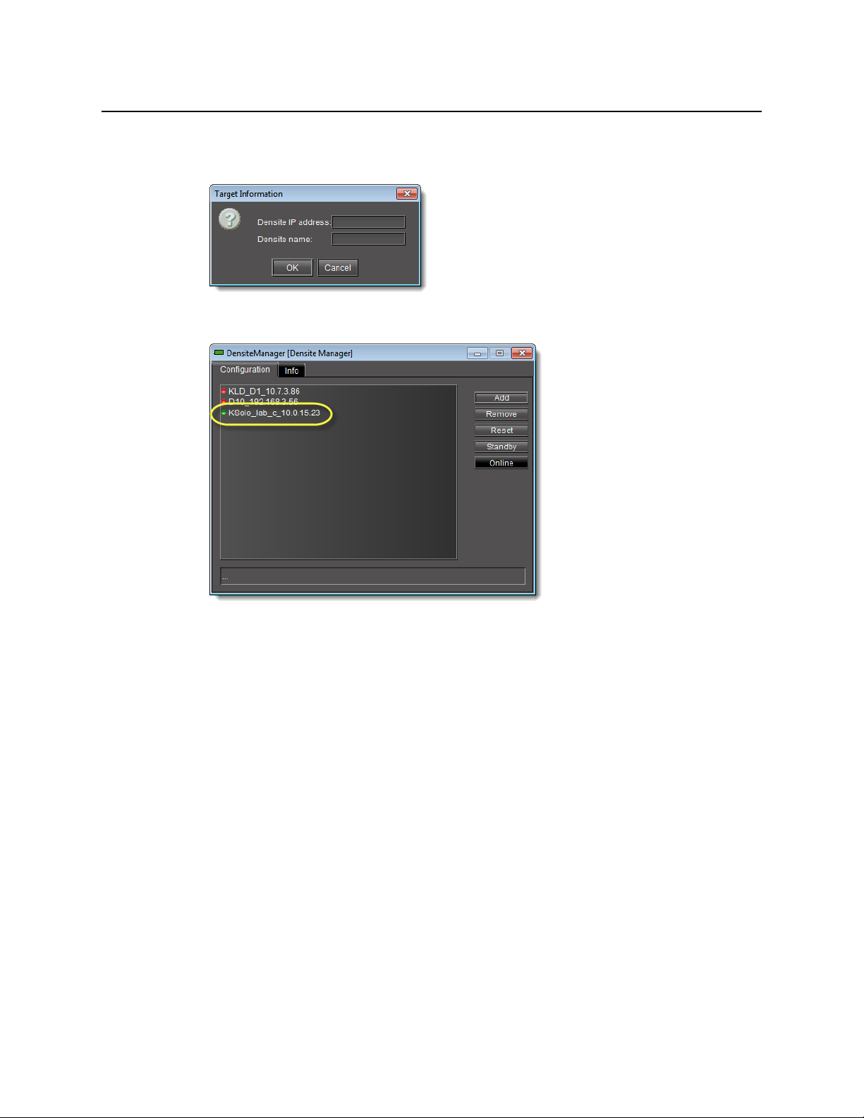
2. In DensiteManager, click Add.
5
Page 10
Getting Started with iControl Solo
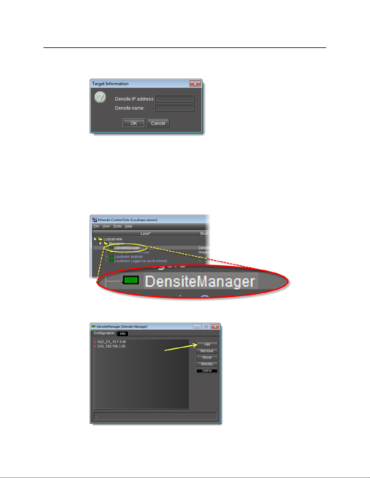
Adding Kaleido-Solo Services
3. In the Target Information window, type the frame’s IP address and a descriptive name for
the new Densité Communicator service, and then click OK.
The new Densité Communicator will be started and added to the list. iControl Solo will
query the corresponding Densité frame and any devices (e.g. cards) it discovers will be
displayed in iControl Solo.
Adding Kaleido-Solo Services
To add a Kaleido-Solo service
1. Open iControl, Solo and double-click DensiteManager in the logical view.
2. In DensiteManager, click Add.
6
Page 11
iControl Solo
User Guide
3. In the Target Information window, type the Kaleido-Solo’s IP address and a descriptive
name for the new service, and then click OK.
The new Kaleido-Solo will be started and added to the list.
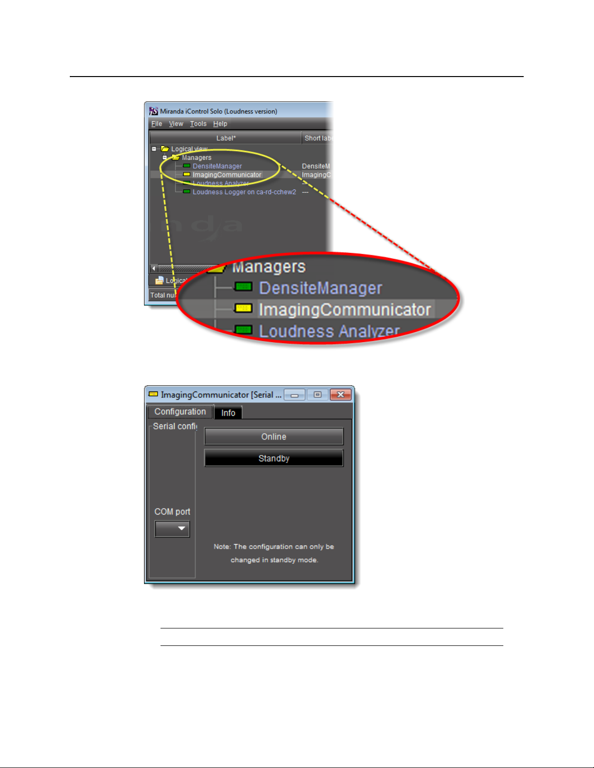
Configuring Imaging Communicator Services
To configure the Imaging Communicator service
1. Open iControl Solo, and double-click ImagingCommunicator in the logical view.
7
Page 12
Getting Started with iControl Solo
Configuring Imaging Communicator Services
2. In ImagingCommunicator, click Standby.
3. In the COM Port list select the COM port you chose when you installed the IC-USB device
Note: COM port can only be selected in Standby mode.
4. Click Online to activate the selected port.
8
Page 13
The Imaging Communicator service will be restarted and iControl Solo will query all
Imaging Series frames interfaced to your computer. Any devices (e.g. cards) housed in the
frames will be displayed in iControl Solo.
Licensing Options
Perform the tasks listed in the following workflow in the prescribed sequence.
Workflow: Requesting and Activating a License for iControl Solo
Workflow: Requesting and activating a license for iControl Solo
In iControl Solo, open Miranda License Manager (see page 9).
1.
Request the desired license (see page 10).
2.
Wait for Miranda to return an activation file.
3.
Upload the activation file to the PC on which you have iControl Solo installed
4.
(see "Activating a License", on page 12).
Activate the license (see page 12).
5.
iControl Solo
User Guide
Opening Miranda License Manager
REQUIREMENT
Before beginning this procedure, make sure you have opened iControl Solo (see page 31).
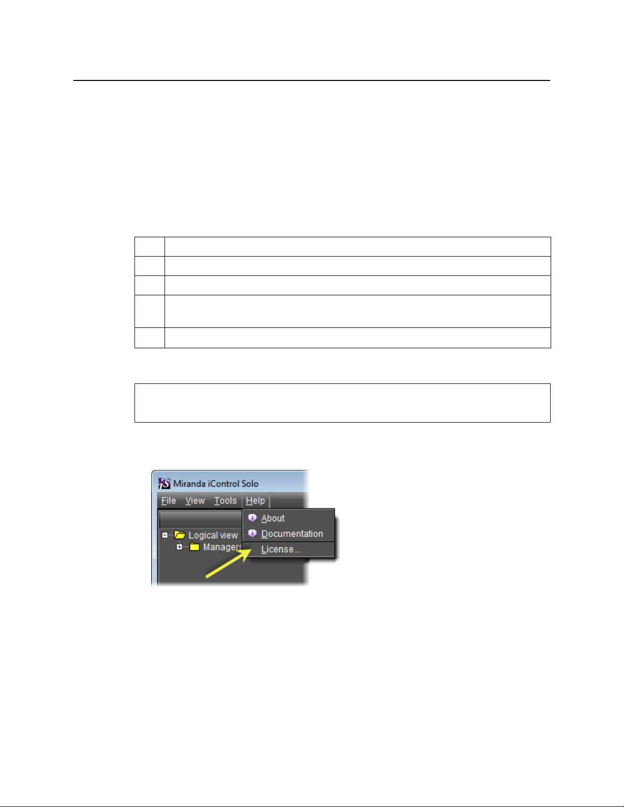
To open Miranda License Manager
• In iControl Solo, on the Help menu, click License.
Miranda License Manager appears.
9
Page 14
Getting Started with iControl Solo
Requesting a License
Requesting a License
IMPORTANT: When licensing for the IC-LOUDNESS-LOG1-SOLO option, the number of licenses
must match the number of devices you with to log from (for example, if you
have seven Kaleido-Solo units, each of which are providing streaming loudness
data to your iControl Solo, then you must have seven IC-LOUDNESS-LOG1-SOLO
licenses).
REQUIREMENTS
Make sure you meet the following conditions before beginning this procedure:
• You have opened Miranda License Manager (see page 9).
• You are able to send and receive e-mail on your client PC.
To request a license
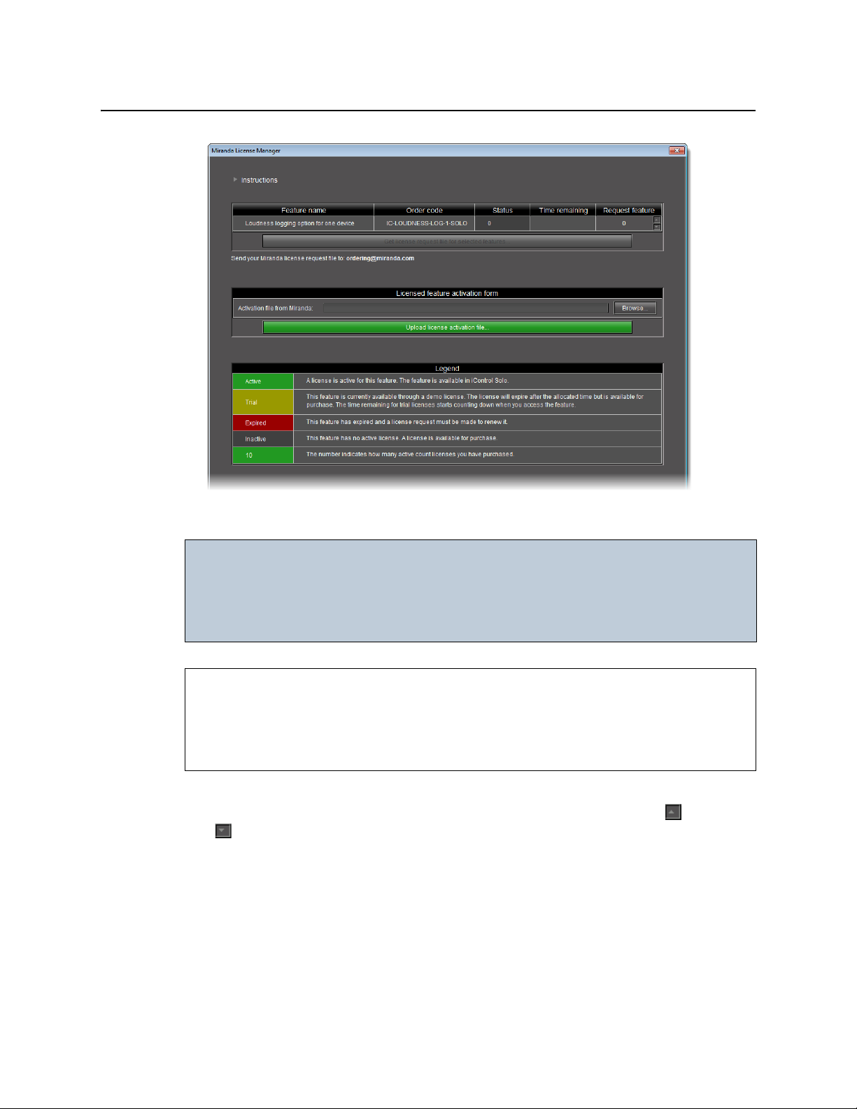
1. In Miranda License Manager, in the Request feature column, use the up () and down
( ) arrows to specify the number of licenses you would like to purchase.
10
Page 15
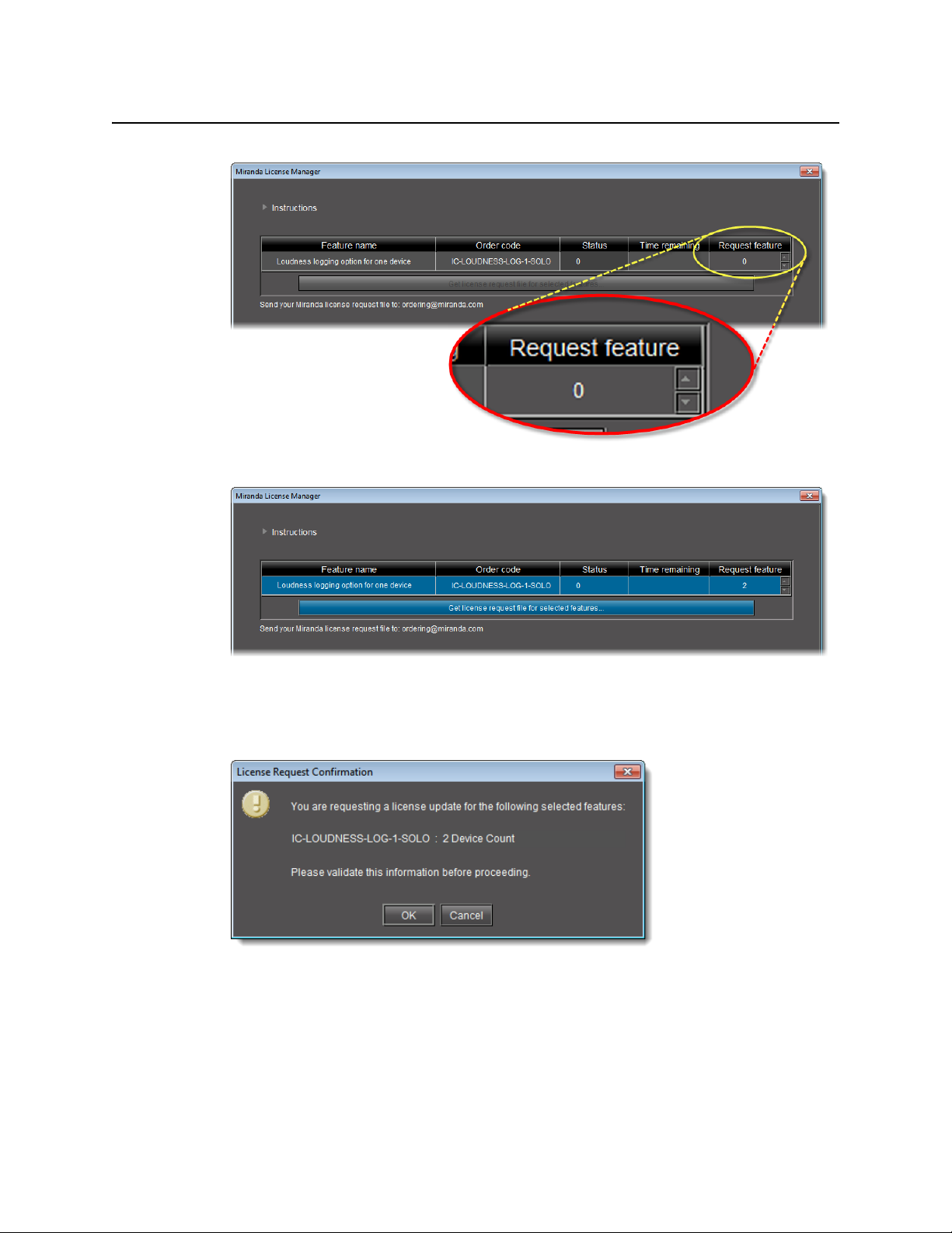
Miranda License Manager before specifying the number of licenses desired
iControl Solo
User Guide
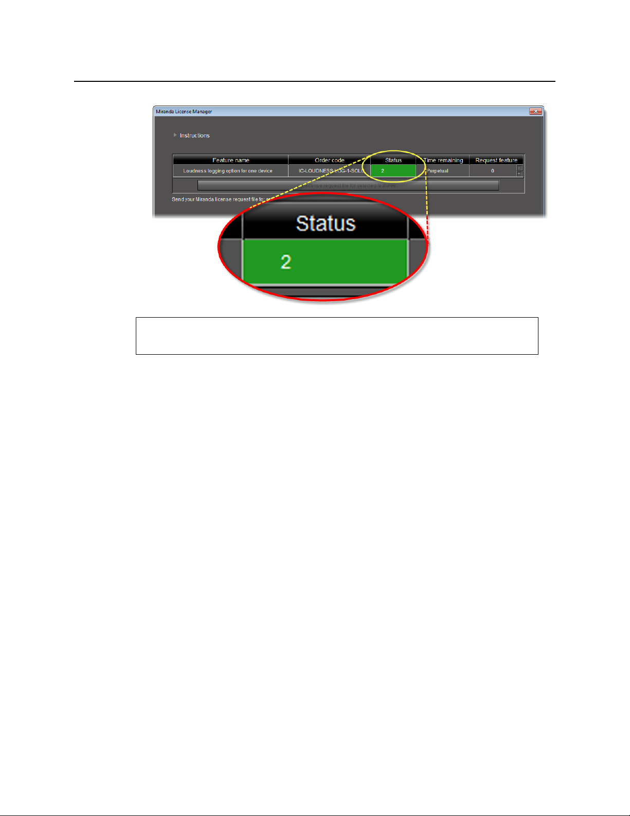
Miranda License Manager after specifying the number of licenses desired
2. Click Download license request file for selected features.
A confirmation message appears.
3. Validate the information listed in the confirmation, and if satisfactory, click OK. If not
satisfactory, click Cancel.
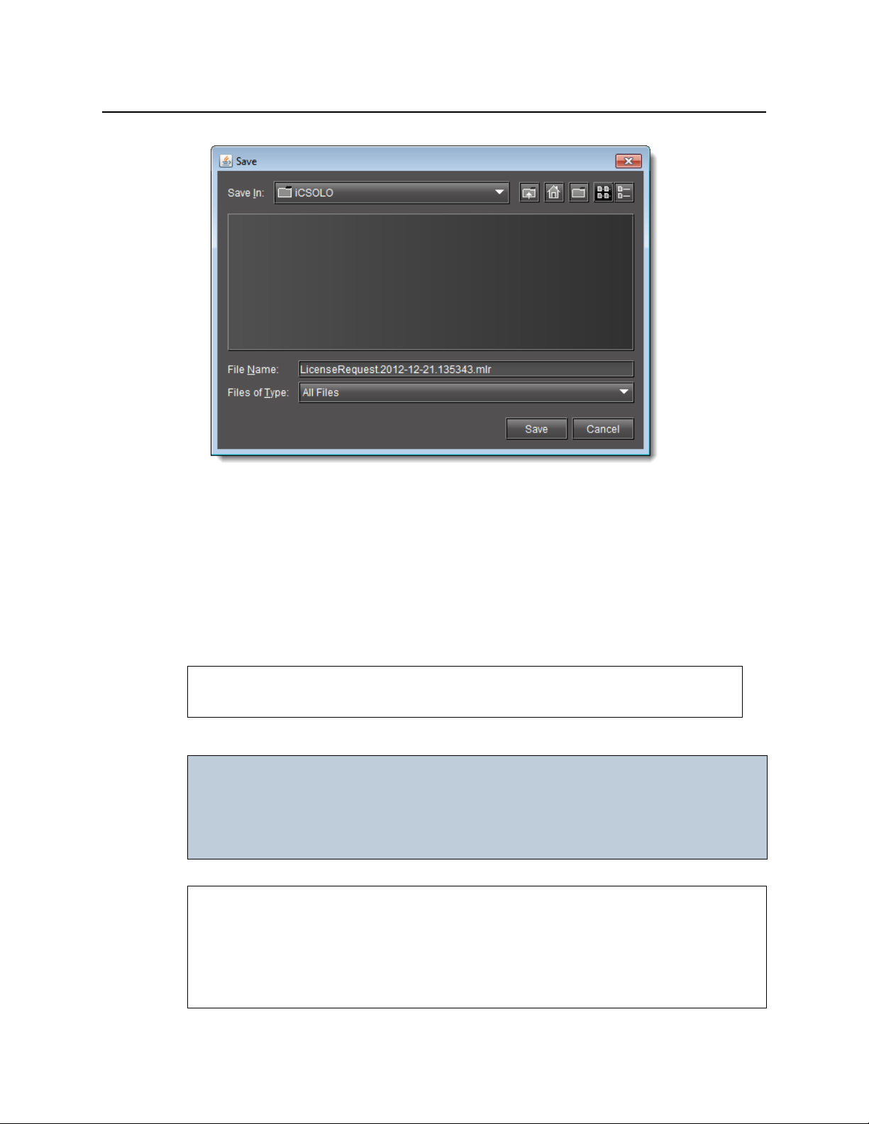
If you clicked OK, you are prompted to save the downloaded license request file.
11
Page 16
Getting Started with iControl Solo
Activating a License
4. Save the MLR file to a convenient location on your hard drive.
5. In your e-mail client application, create a new e-mail with the following recipient:
ordering@miranda.com
6. Attach to this e-mail the MLR file you saved to your local hard drive in step 4, and then send
the e-mail.
The request for an activation file is sent to Miranda. Wait until Miranda provides you with
the activation file before proceeding to the next task in the workflow (see "Workflow:
Requesting and Activating a License for iControl Solo", on page 9).
See also
For more information about licensing, see "License Management", on page 3.
Activating a License
IMPORTANT: When licensing for the IC-LOUDNESS-LOG1-SOLO option, the number of licenses
must match the number of devices you with to log from (for example, if you
have seven Kaleido-Solo units, each of which are providing streaming loudness
data to your iControl Solo, then you must have seven IC-LOUDNESS-LOG1-SOLO
licenses).
REQUIREMENTS
Make sure you meet the following conditions before beginning this procedure:
• You have opened Miranda License Manager (see page 9).
• You have received an activation file from Miranda and it is stored on your client PC’s hard
drive (either a
V2C file or a ZIP file).
12
Page 17
iControl Solo
User Guide
To activate a license
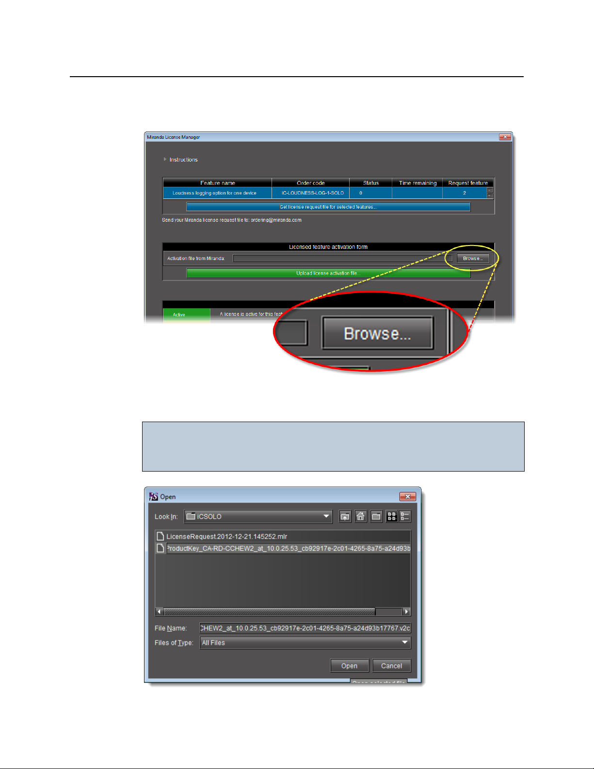
1. In Miranda License Manager, in the Licensed feature activation form area, click Browse.
A browse window appears.
2. Navigate to the directory containing the appropriate activation file.
IMPORTANT: Activation files may be V2C or ZIP files
The file Miranda sends back to you may have a v2c suffix or a zip suffix. In
either case, the steps to follow are the same.
13
Page 18
Getting Started with iControl Solo
Activating a License
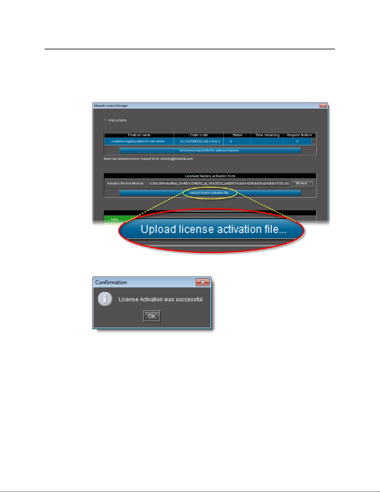
3. Select and then open the file.
In Miranda License Manager, the path and file name of the desired activation file appear
next to the Browse button.
4. Click Upload license activation file.
A confirmation window appears.
In Miranda License Manager, in the row corresponding to the feature for which you
bought licenses, the Status column displays the number of active licenses you have.
14
Page 19
See also
For more information about licensing, see "License Management", on page 3.
iControl Solo
User Guide
15
Page 20

Getting Started with iControl Solo
Activating a License
16
Page 21
Key Concepts
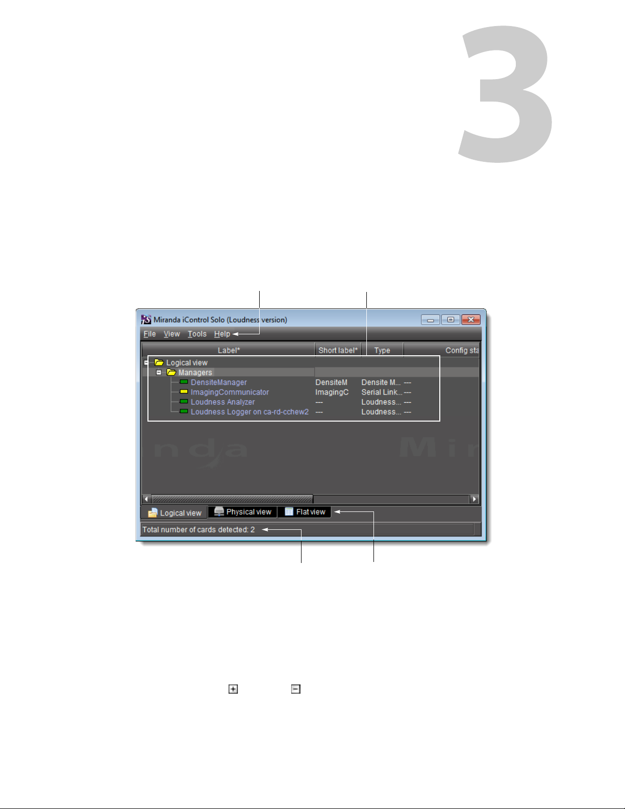
Menu bar Hierarchical navigation area
Sorting tabsStatus bar
iControl Solo Window
When you open iControl, you see the menu bar, the hierarchical iControl Solo area, sorting
tabs for three different iControl Solo views, and a status bar.
Using iControl Solo
The menu bar provides access to iControl Solo’s main features.
The status bar is where iControl Solo displays messages related to its current operations.
The sorting tabs are a way of filtering the information provided in the hierarchical iControl Solo
area to include all devices or a subset.
The hierarchical iControl Solo area is a representation of all the devices interfaced with iControl
Solo.
You can use the plus and minus buttons in the hierarchy to navigate the hierarchical list
views by expanding and collapsing folders and groups (see "Managing Device Groups",
on page 32 for details).
Page 22

Using iControl Solo
Control Panels and Device Parameters
iControl Solo shows the current status of every device and service within your iControl Solo
system. By default, iControl Solo displays the following information for each device:
Status icon Green (OK), yellow (warning), red (error), or grey (not connected) (see "Alarm Sta tu s", on page 22).
Label The device type (by default) or a user-specified name. The text color reflects the device configuration
Short label Abbreviated 8-character label.
Source ID Name of the signal source.
Device type The device type.
Comments Optional; may be entered by the user.
status.
See:
• "Changing Device Information" on page 32
• "Reference Configuration" on page 22
• "Adding Cards to the Reference Configuration" on page 33
• "Removing Cards from the Reference Configuration" on page 34
Config status Whether the device is or is not part of the Reference Configuration, also if there is a mismatch
between the actual and defined device (see "Reference Configuration", on page 22).
Frame Name of the frame housing the device (when applicable).
Slot Number of the slot where the device is located inside the frame (when applicable).
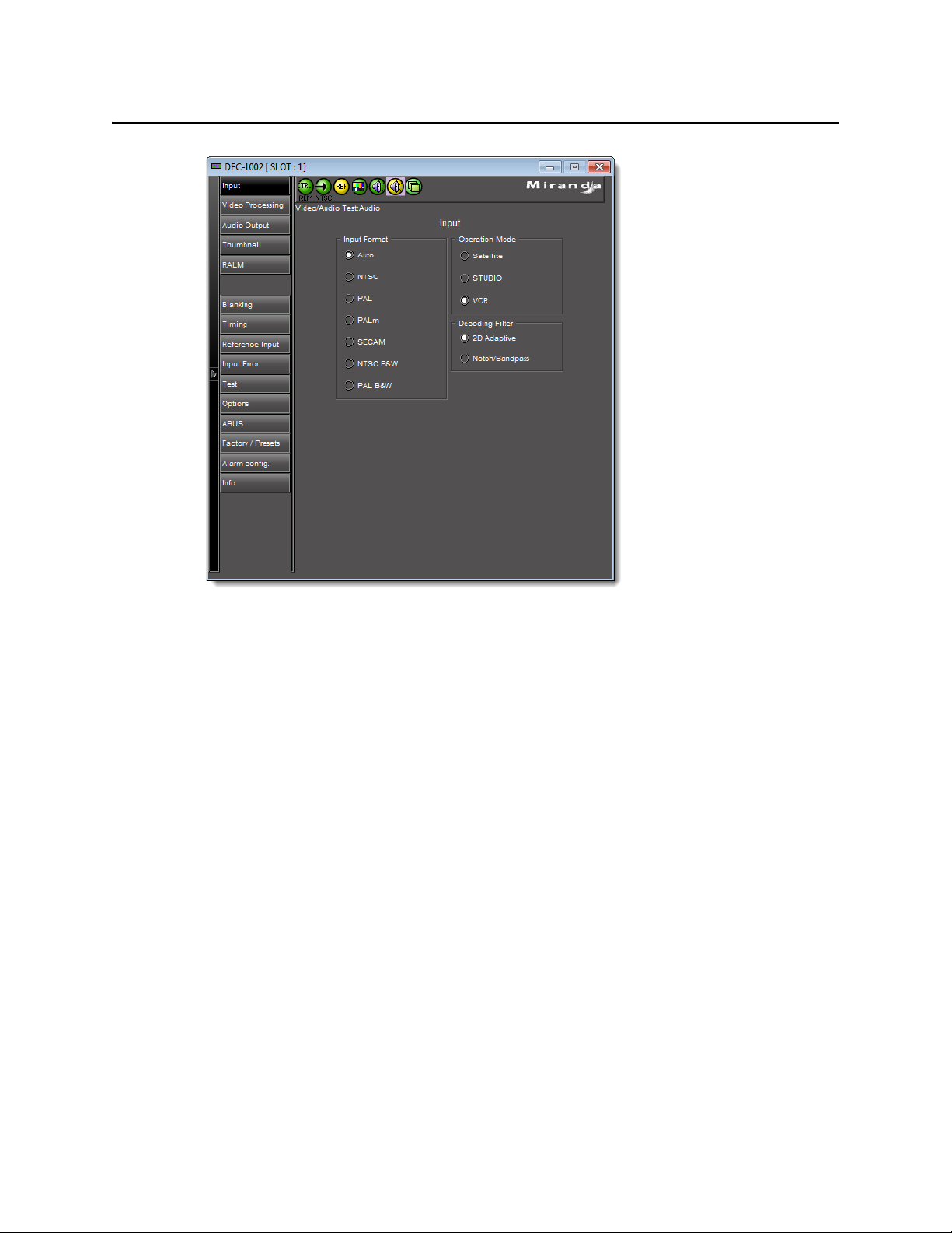
Control Panels and Device Parameters
Most Miranda devices can be controlled using control panels. A control panel is a software
interface that lets you monitor and control various device parameters.
Note: Miranda cards are shipped with Installation & Operation Guides that provide
detailed descriptions of their respective control panels, along with instructions on
their use.
To access the control panel for a device, double-click the device in iControl Solo. Alternatively,
right-click the device name, and then click Show control panel on the shortcut menu.
The device name is displayed at the top of its control panel, along with a dashboard containing
one or more icons representing the status of key device parameters. Error conditions are
indicated by color and by a text message that appears below the dashboard. If more than one
error condition is present, hold the pointer over an icon to continuously display its associated
error message; otherwise the display cycles through all reported errors.
18
Note: If the Control icon on the dashboard is yellow, this indicates that local
card control is active—the card is being controlled from a local hardware
control panel. In such a case, any changes made using the iControl Solo
interface will have no effect on the card.
Page 23

When control panels are open their names are added to the View menu. To bring a specific
panel to the foreground, click its name on the View menu. To close all open panels at once,
click Close all control panels.
Control Panel Tabs
The table below lists common control panel tabs and their typical purposes:
Tab Description
Input Allows input selection, second input operation mode selection, and control of the deglitcher and
Video Processing Contains color-correction parameters that apply to the input signal.
Video Output Allows control over several aspects of the high definition and standard definition video output:
iControl Solo
User Guide
Note: For more information on a control panel, please refer to the
Installation & Operation Guide for the corresponding device.
freeze functions.
aspect ratio conversion, timing control, image quality processing, metadata insertion.
Audio Processing Provides audio processing and delay parameters for the embedded or discrete audio input
Audio Output Provides extended audio processing for the 16 audio channels embedded in the HD/SD outputs,
Timing Provides access to timing adjustments which affect the signal outputs.
Factory/Presets Allows user and device profile management, and restoring of a device’s factory default
Options Describes available options for the device, and provides information on how to enable or disable
Alarm Config. Opens a separate window where alarm status can be monitored and configured.
Info Allows viewing and modifying information about a device (e.g. labels, source ID, comments) to
Info Control Panels
The Info control panel is available for all device types. The Info panel includes device
identification information such as a label, a short label, the device type, comments, source ID,
config status, frame, and slot. You can display the Info panel from the device control panel, or
you can right-click a device in iControl Solo and then click Show info control panel from the
shortcut menu.
channels. These parameters affect both the output audio channels (embedded and AES) and the
audio channels sent to other companion cards.
including audio channels mixing and audio embedding mode.
configuration.
them.
help identifying a specific device in a complex setup.
From the Info panel, you can change the name of the selected device and type comments. By
default, the device name takes the type identification; however, you will find it helpful to
rename devices using meaningful names. Once you change the device name in the control
panel, the new name will be displayed in iControl Solo, making the device easier to locate.
19
Page 24
Using iControl Solo
Devices Groups
Example of an Info control panel for a specific device
Devices Groups
iControl Solo allows you to organize devices into logical groups, making them easier to locate
and to manage. A device group is a folder into which you drag selected devices. You can create
as many device groups and subgroups as you want.
When you create a device group, you automatically create a virtual alarm that displays the
overall status of the member devices. The color of the device group’s folder icon will change
when one or more of its members displays an error or warning status. For example, if one
member device changes status as a result of a critical error, then the group’s folder icon will
turn red. If no devices are assigned to a group, its folder icon will be white.
20
Page 25
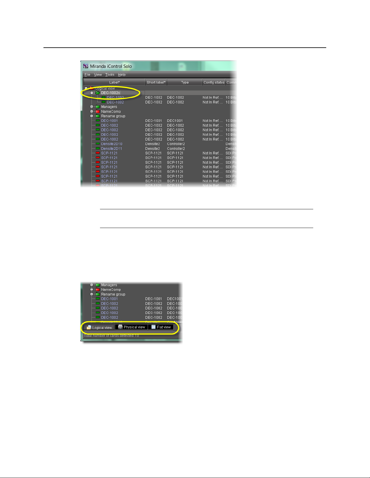
New device group folder (circled)
iControl Solo
User Guide
Views
Note: Device groups can only be created in (and are only visible in) iControl Solo’s
Logical sort mode.
Sorting allows you to determine the way in which devices will be arranged for display in
iControl Solo.
Three views are available by clicking tabs at the bottom of iControl Solo.
iControl Solo tabs (circled)
• Logical view displays all active services and devices interfaced with iControl Solo. The
devices and services may be organized into groups. Groups and their contents are
arranged in alphabetical order. Ungrouped items are displayed at the end of the list. Empty
slots are not shown, unless they are in the Reference Configuration (see "Reference
Configuration", on page 22).
• Physical view arranges the devices relative to their physical connections and network
location. All frame slots are shown. Empty slots show up as Empty, unless the card is
designated as In Ref. Configuration, in which case it will show up as before, but with the
21
Page 26

Using iControl Solo
Alarm Status
• Flat view shows all devices in alphabetical order without any grouping.
Alarm Status
The current status of an alarm determines the color of any on-screen object associated with
that alarm: the LED-like icon to the left of a device or service label, an enclosing folder, etc.
Each possible alarm status is represented by a color. Alarm statuses are dynamically updated.
iControl Solo implements an industry standard
following table describes the color scheme used by iControl Solo to display alarm statuses,
and how they map to the ITU-TX.733 Recommendation:
Color Status ITU-T X.733 Description
White Pendin g — Alarm exists but has not yet been reported. iControl Solo is waiting for the
description missing from slot. Devices are sorted by the name you typed when you
added a Densité Communicator service, and by the number of the serial port where an
Imaging frame is connected.
1
color code definition for all alarms. The
hardware or driver to update the alarm. White is the default status for a new alarm,
before its current status is known. This status should be replaced very quickly,
though it might persist as the result of a slow network connection. If a service is
stopped, then all alarms originating from this service will revert to pending status.
Green Normal Cleared The device, service, or signal is operating within allowable parameters.
Yel l ow Minor Minor/Warning Warning that an error of low importance has occurred.
Orange Major Major Warning that an error of intermediate importance has occurred.
Red Critical Critical Warning that an error of critical importance has occurred.
Gray Unknown Indeterminate Failure to get the status of an alarm provider, even though the source device has
Blue Non-
existent
Black Disabled Not supported Alarm exists but has been disabled at the source. Some devices can have certain
Reference Configuration
The reference configuration is a feature of iControl Solo that allows you to keep track of
important cards, or groups of cards. If a card is removed from a slot, the default behavior in
iControl Solo is for the card to disappear from the list in the Logical and Global views. In the
been detected. This could happen, for example, as the result of (1) a lost network
connection, or (2) a loss of signal that would trigger a critical alarm for signal
presence but leave all other related alarms in an unknown status (e.g. the freeze or
black status is unknown if a signal is not present).
— A pseudo-status representing an alarm that has been removed (or was never
added). If an alarm provider is removed—for example, if a card is removed from a
frame—the virtual alarm will be unable to detect an alarm status, and will
therefore report the “non-existent” status as blue.
alarms disabled on the hardware itself, resulting in these alarms appearing black.
1. Default alarm severities in iControl Solo are compliant with the intent of ITU-T Recommendation X.733, Information
Technology – Open Systems Interconnection – Systems Management – Part 4: Alarm Reporting Function
22
Page 27

Network view, the device name is replaced by the slot number followed by the indication
Empty.
When you to designate a card as part of the reference configuration, then the name of the
card and the slot number it occupies are retained. If the card is removed, its label will be visible
as before, but with the description
Loudness Logging and Analyzing
Certain devices like the Kaleido-Solo are capable of monitoring the loudness of audio streams.
The data generated from monitoring may be sent to your client PC where iControl Solo’s
Loudness Logger can record and archive this stream of loudness data to a dedicated local
folder.
After (or even during) the logging of loudness data, iControl Solo’s Loudness Analyzer can plot
a log file’s loudness, making visible the data in units of LUFS (EBU) or LKFS (A85) over the time
period covered by the file. Loudness Analyzer allows you to zoom into the data plot as well,
effectively taking a subset of the time frame analyzed while increasing data granularity in the
chart.
Additionally, with Loudness Analyzer, you may edit analysis parameters as well as showing or
hiding certain data plots (e.g. choosing to show or hide the DIALNORM and Short-term
Momentary 1 data plots on the chart).
iControl Solo
User Guide
Missingfromslot appended.
See also
For more information about:
• Loudness Logger, see page 23.
• Loudness Analyzer, see page 25.
• loudness logging and analyzing, see "Working with Loudness Logger and Loudness
Analyzer", on page 34.
• Loudness Logger and Loudness Analyzer, see the Loudness Log Analyzer User Manual
(M948-9000-100).
Loudness Logger
Loudness Logger allows you to start and stop the logging of loudness data streams coming
from external audio sources, such as Kaleido-Solo. When you initiate logging of a loudness
data stream, you are streaming the data to a log file on your client PC.
23
Page 28

Using iControl Solo
Loudness Logger
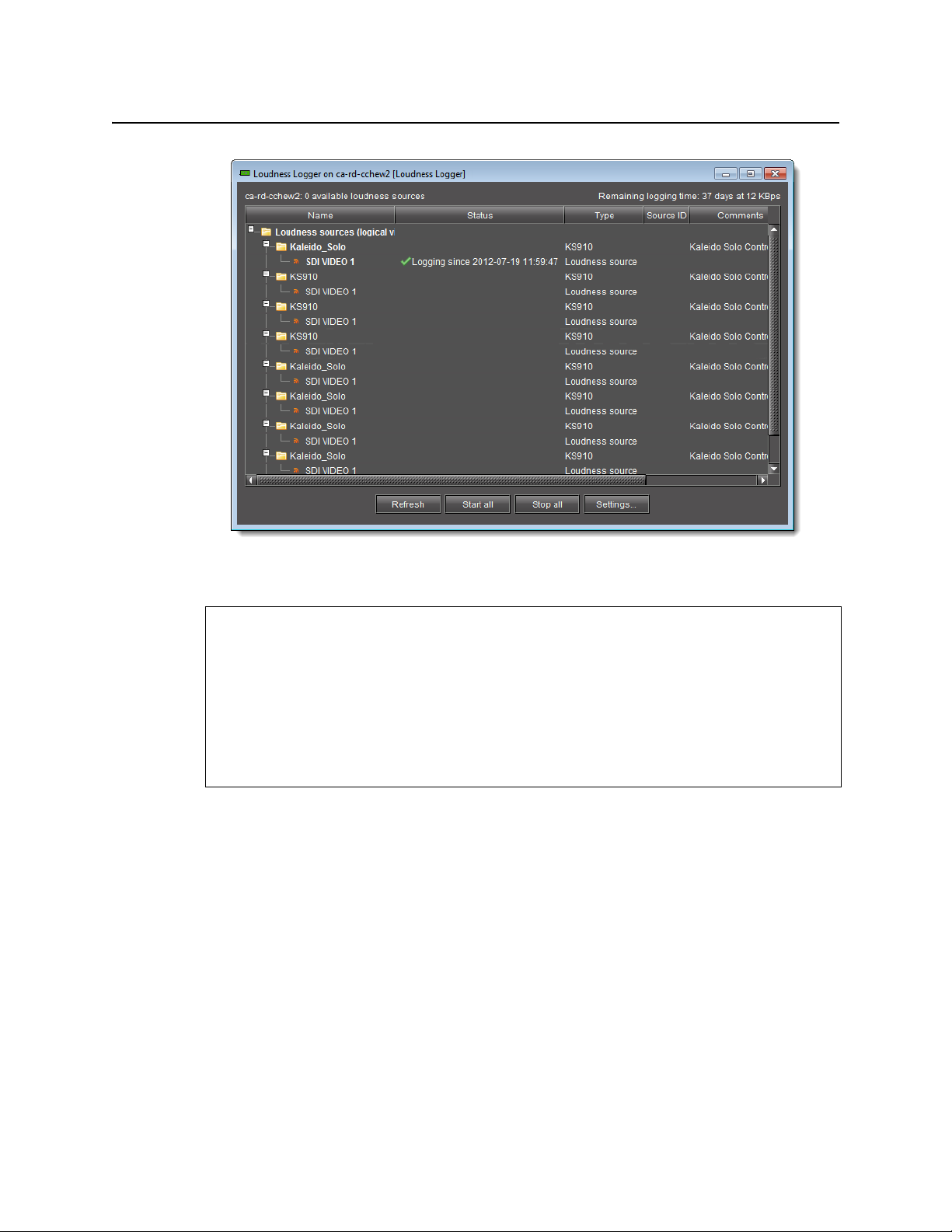
Loudness Logger
UI Element Description
Main window Displays available loudness data streams
Refresh Refreshes the main window
Start all Starts logging all available loudness data streams
Stop all Stops logging all available loudness data streams
Settings Allows you to specify the location on your local file system where you would like to save
loudness data
IMPORTANT: Make sure you have sufficient storage space for loudness data
When specifying a location for storing loudness data, make sure you have
enough storage space available. If, when logging loudness data, the logger runs
out of space, it will stop logging.
Miranda recommends using a controlled remote storage device to ensure
adequate storage space.
Please see Tab le 3-1 , on page 25 for guidelines on estimating storage space
requirements.
24
Page 29
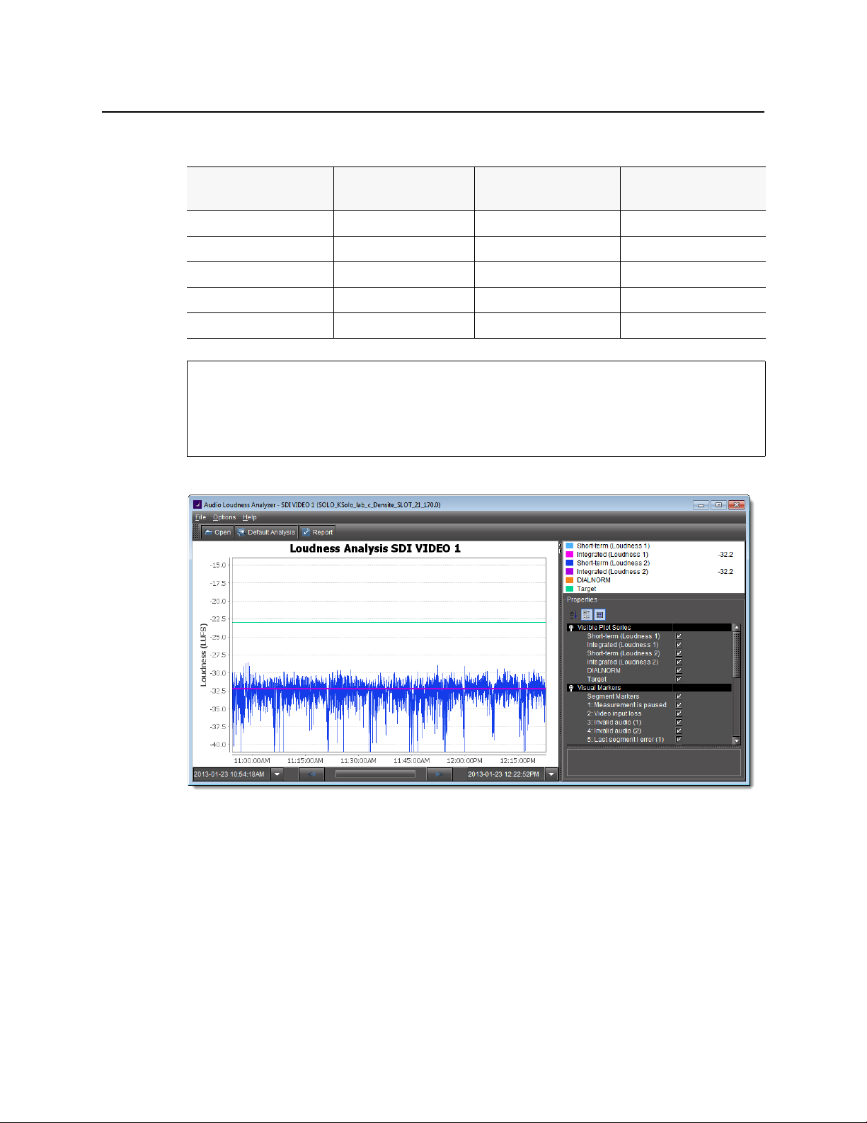
Table 3-1: Differential bit rate of loudness raw data from various devices
iControl Solo
User Guide
Device Number of audio
programs
KS-910 1-2 170-210 14.7-18.2
XVP-3901 1-8 170-450 14.7-39
EAP-3901 1-8 170-450 14.7-39
AMX-3981 1-8 170-450 14.7-39
ADX-3981 1-8 170-450 14.7-39
Bitrate (Bytes/second) Bitrate (MBytes/day)
See also
For more information about:
•Working with Loudness Logger and Loudness Analyzer, see page 34.
• Loudness Analyzer, see page 25.
Loudness Analyzer
Loudness Analyzer is a powerful tool for graphically depicting an audio source’s loudness
data over a period of time. The power of this tool lies primarily in its configurability of analysis
parameters, including the applicable loudness standard, relative gating, and short-term
window. As well, Loudness Analyzer allows you to zoom into a data plot. Each zooming action
triggers a new analysis of loudness data from source, for the requested time period
(configurable start and stop times) and given the configured analysis parameters.
Additionally, one can choose to incrementally display or hide plot series. For example, you
may decide to display only Short-term Momentary 1, Integrated Momentary 1, and DIALNORM
data while hiding the remaining series in order to unencumber the visual chart.
25
Page 30

Using iControl Solo
Loudness Analyzer
See also
For more information about:
• Loudness Analyzer, see the Loudness Log Analyzer User Manual (M948-9000-100)..
• Loudness Logger, see page 23.
•Working with Loudness Analyzer and Loudness Logger, see page 34.
Data plot chart (circled in red)
Visible plot series: Color-coded legend and values
26
Page 31
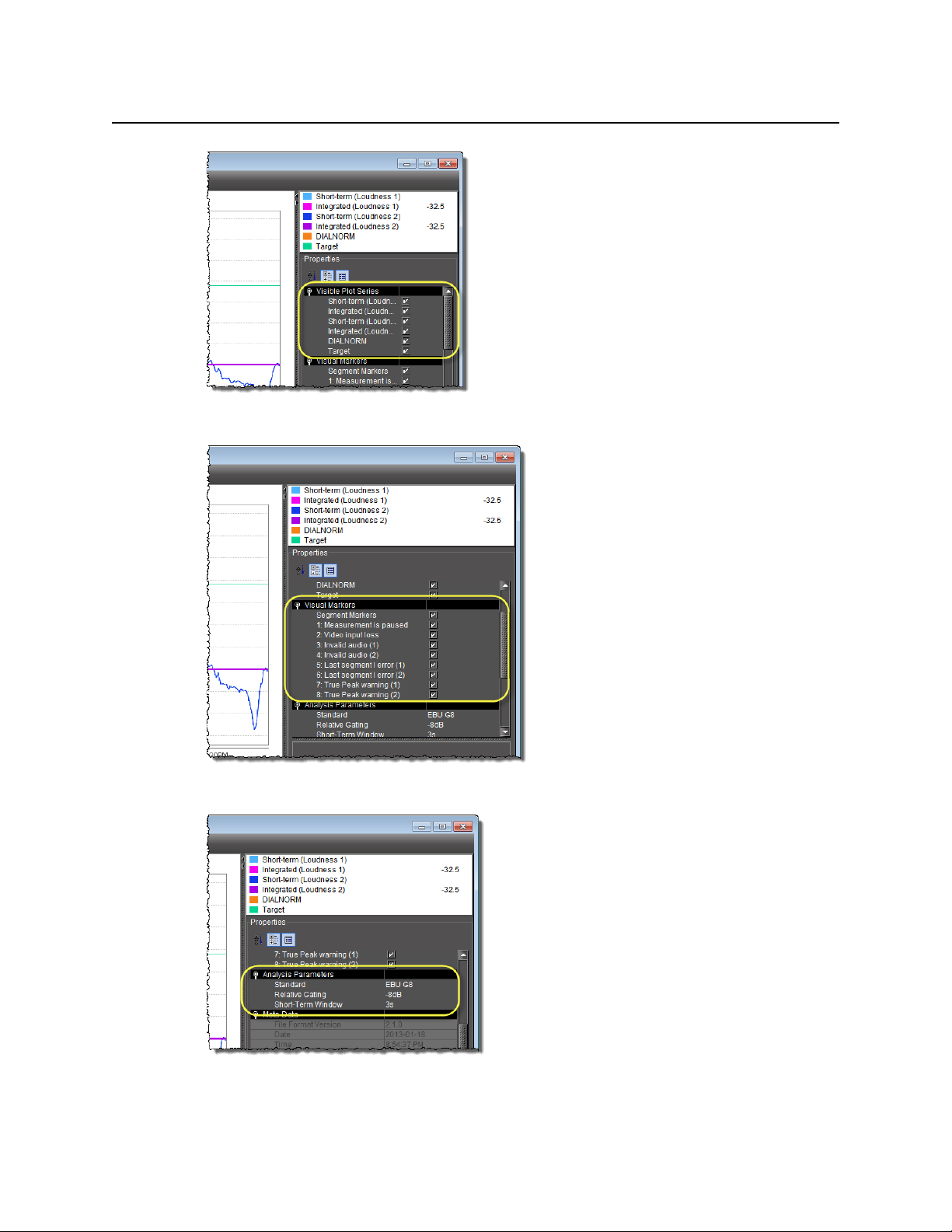
Visible plot series: Display options
iControl Solo
User Guide
Visual Markers: Display options
Properties: Analysis parameters
27
Page 32
Using iControl Solo
Densité Upgrade Manager
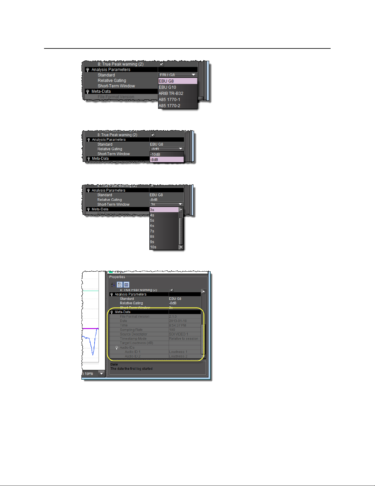
Properties: Analysis parameters (available standards)
Properties: Analysis parameters (relative gating)
Properties: Analysis parameters (short-term window)
Meta-data (not editable)
Densité Upgrade Manager
Densité Upgrade Manager is an iControl Solo utility allowing you to manage the firmware
and software versions of individual cards without having to put entire Densité frames into
operational Standby mode. Densité Upgrade Manager allows you to effectively toggle
28
Page 33

iControl Solo
User Guide
among Densité card firmware versions. From time to time, new versions become available,
and Densité Upgrade Manager allows you to upload these.
IMPORTANT: System behavior
The Densité Upgrade Manager included with any version of iControl Solo
(starting with version 6.00), supports all Densité card types, including those that
do not yet exist.
For example, if a brand new Densité card, ABC-1234, is installed in a Densité frame
visible to a version of iControl Solo that is, at the time, three years-old (but still
version 6.00 or greater), the ABC-1234 card would be visible within Densité
Upgrade Manager.
Firmware and software is bundled into single upgrade packages. That is, a package contains
one version of firmware for a given Densité card and one version of software. By upgrading a
card with a given package, you are changing both the installed firmware and software to
those versions of each within the upgrade package.
IMPORTANT: The version numbering of packages represents a system of incrementation
belonging ONLY to the package and not to the respective version numbering of
firmware and software.
Note: Densité Upgrade Manager does not allow you to upgrade, downgrade, or
roll back firmware separately from software. Changing an installed package
necessarily implies changing the component firmware AND software to those
versions of each embedded within the introduced package.
See also
For more information about:
• Upgrading, downgrading, and rolling back firmware and software of Densité cards,
see "Working with Densité Upgrade Manager", on page 51.
•The Densité Upgrade Manager user interface including icon colors and their meanings,
see "User Interface of Densité Upgrade Manager", on page 30.
29
Page 34
Using iControl Solo
User Interface of Densité Upgrade Manager
User Interface of Densité Upgrade Manager
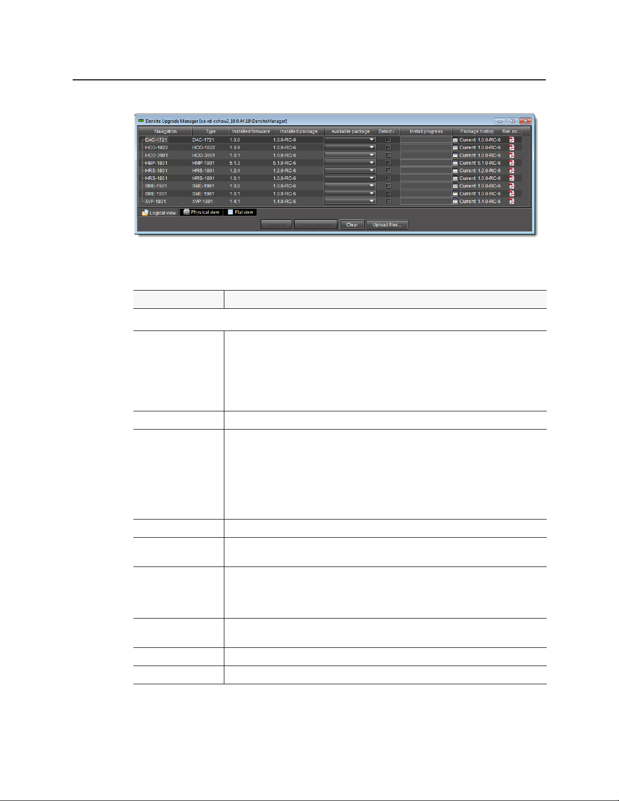
Densité Upgrade Manager
Densité Upgrade Manager UI descriptions
Item Description
--- Columns ---
Navigation The tree structure in this column graphically situates Densité cards, and their modules if
applicable, in the context of several different navigation method, as follows:
• Logical view: a logical arrangement (sorted by type)
• Physical view: a hierarchy representing the nested physical componentry
(e.g. appserver > Densité frame > slot > card)
• Flat view: a flat listing of the Densité cards in alphabetical order.
Typ e Type of D ensité card
Installed firmware Installed firmware version and firmware upgrade path.
If no package is selected under Available package, only the installed firmware version appears
in this column. If a package is selected, the upgrade (or downgrade) path appears.
If you would like to determine if firmware will be installed in the installation of the selected
package, an upgrade path showing X —> X in this column indicates there will be no new
installation of firmware. By contrast, an upgrade path showing X —> Y indicates firmware will
be installed.
Installed package Installed package version and package upgrade path.
Available package Selectable list of packages (relevant to a given Densité card) available to be installed. The
version numbers listed are package numbers and not firmware numbers.
Select / Bypass Selection tool indicating which cards will have their respectively selected available packages
installed once the Upgrade or Force upgrade button is pressed. Additionally, if a package is
selected for a card and you would like for it to remain selected but not installed in the next
upgrade, you may clear the Select / Bypass checkbox to make this happen.
Install progress The progress bar measuring the current installation of a package. After an installation, this field
displays a status message of the last installation attempt.
Package history Logs of all package installations for each Densité card.
Rel. notes Link to the release notes for the version of firmware embedded within the installed package.
30
Page 35

iControl Solo
User Guide
Densité Upgrade Manager UI descriptions (
Item Description
--- Buttons ---
Upgrade Click to begin installing the selected packages (whether upgrade, downgrade, or rollback) to
Force upgrade Click to begin installing the selected packages to their respective cards (same behavior as the
Clear Click to clear all selections from the Available package column and all messages from the
Upload files Click to upload an upgrade package file.
Detailed Directions
Opening iControl Solo
Continued
their respective cards.
Upgrade button). However, in all cases where the firmware embedded within selected
packages have the same version numbers as the installed firmware, no firmware will be installed
from the selected package (in theory because it is the same version).
In order to override the Upgrade button’s behavior of NOT installing a save-version firmware
from a selected package, you must click Force upgrade.
Select / Bypass column.
)
To open iControl Solo
• Use the iControl Solo shortcut on your desktop.
iControl Solo appears.
Closing iControl Solo
To close iControl Solo
•Do one of the following:
• Close all iControl Solo windows,
OR,
• On iControl Solo’s File menu, click Quit.
All changes are automatically saved.
Opening Control Panels
To open the control panel for a device
• In iControl Solo, right-click the device, and then click Show control panel on the shortcut
menu. Alternatively, double-click the device.
The device’s control panel appears.
31
Page 36

Using iControl Solo
Opening Info Control Panels
Opening Info Control Panels
To access the Info control panel for a device
1. In iControl Solo, double-click the device.
The device control panel appears.
2. Do one of the following:
• Select the Info tab,
OR,
• In iControl Solo, right-click the device, and then click Show info control panel on the
shortcut menu.
Changing Device Information
Some device information can be customized from the device’s Info control panel. Changes
made in the control panel are immediately applied to the device.
• The device name appears in the Label box.
• You can modify the source ID and add comments in the corresponding boxes.
Renaming Devices
To rename a device
1. Open the Info window for the device you wish to rename (see "Opening Info Control
Panels", on page 32).
2. Type the new name in the Label box.
The changes are immediately applied.
Managing Device Groups
With iControl Solo, you can create as many device groups as necessary for your system, and
then place the various devices into the appropriate groups. A device can only be a member of
one group.
Creating Groups
To cre ate a gr oup
1. In iControl Solo, click Logical view.
2. Right-click the location for the new group (the root folder, or another folder within the
hierarchical structure) and then click Add Group on the shortcut menu.
The Group name window appears.
32
Page 37
iControl Solo
User Guide
3. Type a name for the group (e.g. “satellite” or “remote”), and then click Create Group.
The group appears as a new folder in the chosen location.
Moving Groups
To move a gro u p
1. In iControl Solo, right-click the group you wish to move, and then click Cut on the shortcut
menu.
2. Right-click the destination folder, and then click Paste on the shortcut menu.
The group appears as a new folder in the chosen location.
Renaming Groups
To rename a group
1. In iControl Solo, select the group folder you wish to rename.
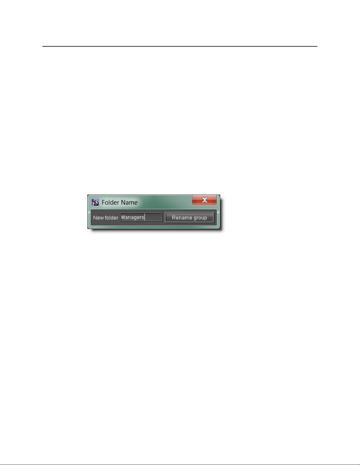
2. Right-click the group folder and then click Rename group.
The Folder Name window appears.
Folder Name window
3. Type a new name for the group, and then click Rename group.
The new group name appears for the chosen folder.
Removing Groups
To remove a group
1. In iControl Solo, expand the group folder you wish to remove.
2. Remove all devices from the group folder by dragging them to another folder or to the root
of the folder structure (only empty groups can be removed).
3. Right-click the empty group folder, and then click Remove group on the shortcut menu.
4. When prompted to confirm the removal, click Ye s .
The group no longer appears in iControl Solo.
Adding Cards to the Reference Configuration
The reference configuration (see page 22) is a way to keep track of cards or groups of cards
important to your setup.
To add a card to the reference configuration
• In iControl Solo, right-click the card you wish to add, and then click Add to reference
configuration on the shortcut menu.
33
Page 38

Using iControl Solo
Removing Cards from the Reference Configuration
The phrase In Ref. Configuration appears in the Config status column.
Note: If this card is physically removed from its slot, the card name remains in the
Label column, along with the phrase Missing from slot.
Removing Cards from the Reference Configuration
To remove a card from a reference configuration
• In iControl Solo, right-click the card you wish to remove, and then click Remove from
reference configuration.
The phrase Not In Ref. Configuration appears in the Config Status column.
Working with Loudness Logger and Loudness Analyzer
There are several tasks you can perform related to both logging and analyzing loudness data
in iControl Solo. Certainly, before you do anything else, you must make sure your system is
properly configured. You must also make sure you log before you analyze. While the sequence
of these tasks may seem obvious, the sequence of other required tasks may not be. The
following is an approved workflow for configuring, logging, and analyzing loudness data in
iControl Solo.
Sample workflow: Logging and analyzing loudness
Open Loudness Logger (see page 35).
1.
Specify a location in your local file system where you would like loudness data to be saved
2.
(see page 37).
Log loudness data for the desired audio stream (see "Logging an Audio Stream’s Loudness
3.
Data", on page 39).
Stop the loudness log recording (see page 40).
4.
Open Loudness Analyzer (see page 36).
5.
Configure general Loudness Analyzer settings (see page 40).
6.
Open a loudness log file (see page 44).
7.
[OPTIONAL] Zoom into Loudness Analyzer’s da ta pl ot (s e e page 47).
8.
[OPTIONAL] Configure loudness analysis parameters for this data plot (see page 45).
9.
[OPTIONAL] Generate a loudness analysis report (see page 49).
10.
See also
For more information about:
• Logging and analyzing loudness data, see page 23.
• Loudness Logger, see page 23.
• Loudness Analyzer, see page 25.
34
Page 39
iControl Solo
User Guide
See also
(Continued)
For more information about:
• Loudness Logger and Loudness Analyzer, see the Loudness Log Analyzer User Manual
(M948-9000-100).
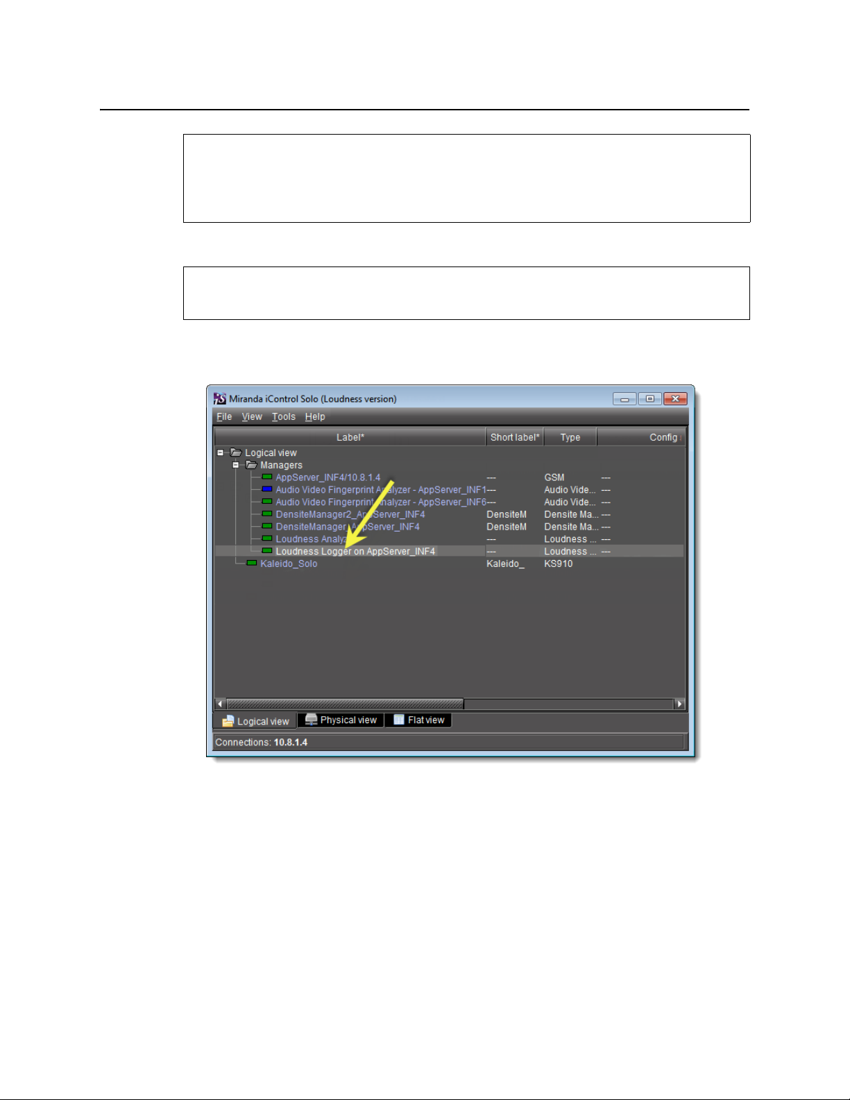
Opening Loudness Logger
REQUIREMENT
Before beginning this procedure, make sure you have opened iControl Solo (see page 31).
To open Loudness Logger
• In iControl Solo, double-click the desired Loudness Logger.
Loudness Logger appears.
35
Page 40
Using iControl Solo
Opening Loudness Analyzer
Opening Loudness Analyzer
REQUIREMENTS
Make sure you meet the following conditions before beginning this procedure:
• The PC running iControl Solo is connected to a device which is streaming loudness
values, such as a Kaleido-Solo.
• You have already logged loudness data (see "Logging an Audio Stream’s Loudness Data",
on page 39).
• You have opened iControl Solo (see page 31).
To open Loudness Analyzer
• In iControl Solo, double-click Loudness Analyzer.
36
Page 41
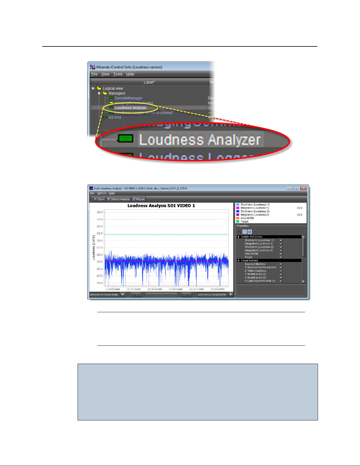
Loudness Analyzer appears.
iControl Solo
User Guide
Note: Loudness Analyzer is timezone-agnostic, meaning it displays a data plot’s
time code as UTC (coordinated universal time). When you configure your general
Loudness Analyzer settings, make sure you set the timezone to that of the signal
being analyzed.
Specifying a Location for Saving Loudness Data
IMPORTANT: Make sure you have sufficient storage space for loudness data
Ensure you have enough storage space available for loudness data at the
specified location. If, when logging loudness data, the logger runs out of space,
it will stop logging.
Miranda recommends using a controlled remote storage device to ensure
adequate storage space.
37
Page 42

Using iControl Solo
Specifying a Location for Saving Loudness Data
REQUIREMENTS
Make sure you meet the following conditions before beginning this procedure:
• The PC running iControl Solo is connected to a device which is streaming loudness
values, such as a Kaleido-Solo.
• You have opened iControl Solo (see page 31).
To specify a location for saving loudness data
1. In Loudness Logger, select the loudness source.
2. Click Settings.
3. In the Loudness Logger Settings window, click the elipsis button to browse for the
location in your local file system where you would like to save loudness data.
4. Click Apply.
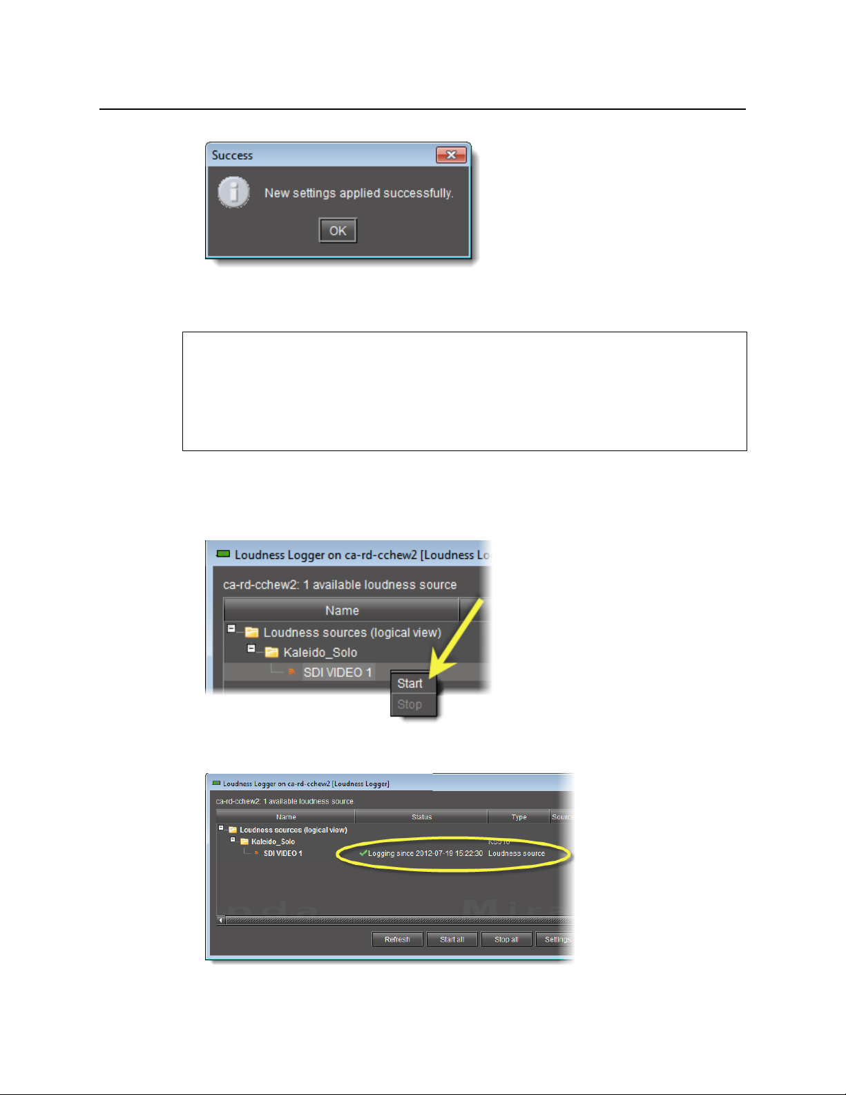
If you chose a valid path, the Success message appears.
38
Page 43
Logging an Audio Stream’s Loudness Data
REQUIREMENTS
Make sure you meet the following conditions before beginning this procedure:
• There is a device streaming loudness values, such as a Kaleido-Solo, visible to
iControl Solo.
• You have opened Loudness Logger (see page 35).
To log an audio stream’s loudness data
iControl Solo
User Guide
1. In Loudness Logger, find the loudness source for which you would like to create a log.
2. Right-click the source and click Start.
Loudness Logger begins logging loudness data from the indicated source.
39
Page 44

Using iControl Solo
Stopping a Loudness Log Recording
Stopping a Loudness Log Recording
REQUIREMENT
Before beginning this procedure, make sure you have opened Loudness Logger
(see page 35).
To stop a loudness log recording
1. In Loudness Logger, find the audio source whose loudness data you would like to stop
recording.
2. Right-click this audio source and click Stop.
The Status column should be blank indicating that logging has stopped for this audio
source.
Configuring General Loudness Analyzer Settings
Perform this procedure to define time zone as well as search parameters when searching for
loudness log files.
To configure Loudness Analyzer general settings
1. In Loudness Analyzer, on the Options menu, click View Settings.
40
Page 45

The Settings window appears.
iControl Solo
User Guide
2. Select the timezone that matches your logs.
Note: Loudness Analyzer is timezone-agnostic, meaning it displays a data plot’s
time code as UTC (coordinated universal time). When you configure your general
Loudness Analyzer settings, make sure you set the timezone to that of the signal
being analyzed.
3. Select Reset analysis when a marker is detected if you would like for the integrated value
to reflect only those data belonging to the segment.
41
Page 46

Using iControl Solo
Configuring General Loudness Analyzer Settings
By contrast, if you would like for your integrated value to reflect the data belonging to the
entire analysis range, then clear this check box.
4. Next to Maximum level of directory nesting in search, use the Up and Down arrow
buttons to select the number of nested levels in which you would like Loudness Analyzer
to search for log files.
42
Notes
• Selecting 3, for example, instructs Loudness Analyzer to search in the
directory named in the path you will define later when you open a loudness
log file and then within the next three nested levels down.
•If you select0, Loudness Analyzer only searches for log files within the
immediate level of the directory named in the path.
• The deeper you search into nested directories, the slower the search
operation will be.
5. Next to Loudness Range in Plot, do ONE of the following:
• Select a preset loudness range to be visible in your data plot (taking note of the range
values).
Page 47

OR,
1. Select Custom.
iControl Solo
User Guide
2. Manually enter a custom range.
6. Click OK.
43
Page 48
Using iControl Solo
Opening a Loudness Log File in Loudness Analyzer
Opening a Loudness Log File in Loudness Analyzer
REQUIREMENT
Before beginning this procedure, make sure you have opened Loudness Analyzer
(see page 36).
To open a loudness log file
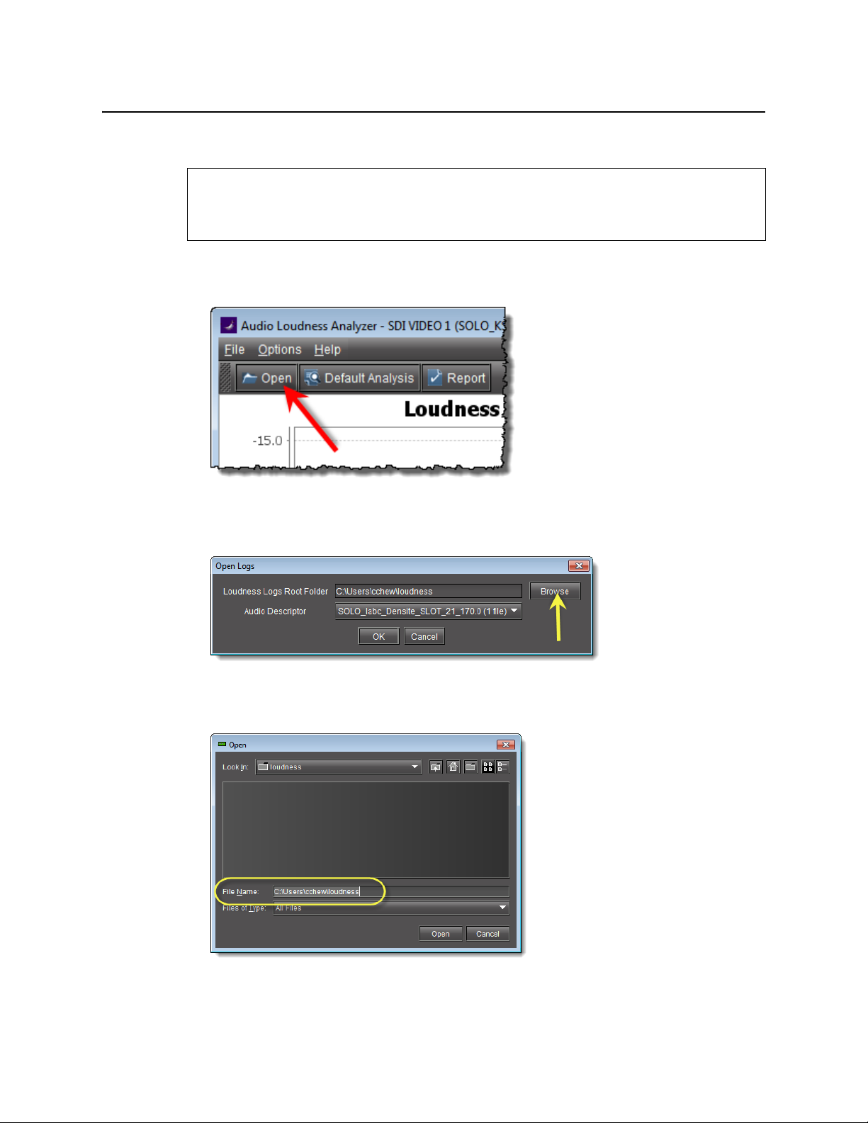
1. In Loudness Analyzer, click Open.
The Open Logs window appears.
2. Next to Loudness Logs Root Folder, click Browse.
3. In the Open window, in the File Name box, type the path to the directory containing the
loudness data.
44
4. In the Open Logs window, in the Audio Descriptor list, select the desired loudness dataset
to analyze.
Page 49
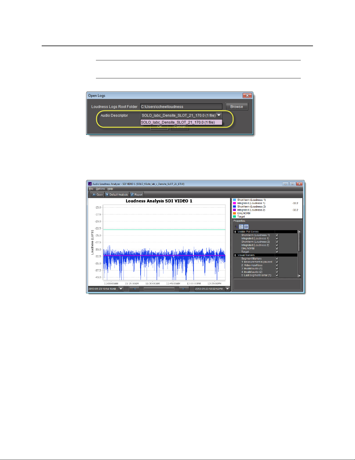
Note: The dataset may contain one file or several files. The number of files in each
dataset is indicated in parentheses.
5. Click Open.
6. In the Open Logs window, click OK.
The Loudness Analysis data plot is populated with the loudness data from the log file.
iControl Solo
User Guide
Configuring Loudness Analysis Parameters
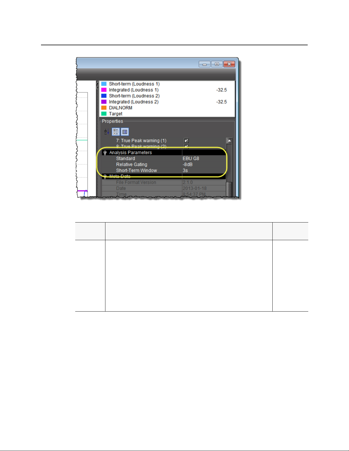
There are three loudness analysis parameters you may configure:
• Loudness standard
• Relative gating
• Short-term window
45
Page 50
Using iControl Solo
Configuring Loudness Analysis Parameters
Configurable loudness analysis parameters
Parameter
name
Standard The program compliance loudness standard against which the loudness data will be
Description Data set
measured.
• EBU G8 refers to the now-obsolete version of EBU-R128 recommending a gate value
of -8LU. The currently recommended value is -10LU.
• A85 1770-1 leaves the threshold level up to broadcasters and recommends an
anchor when available and a gate if necessary (used in USA, Canada).
• A85 1770-2 recommends a gat e is ALWAYS enabled, having a threshold set to -10LU
(used in the European Union).
• ARIBTR-B32 is based on A85 1770-2 with a recommended threshold of -24LKFS
(absolute gate at -70LKFS, -10LU relative gate, 400ms sample blocks).
•EBUG8
•EBUG10
•ARIB TR-B32
• A85 1770-1
• A85 1770-2
46
Page 51

iControl Solo
User Guide
Configurable loudness analysis parameters (
Parameter
name
Relative
Gating
Short-Term
Window
a. Once loudness data is plotted in Analyzer, you should expect for the Short-Term Window plot series
not to begin until one cycle of its configured duration to have elapsed. This is due to there not being
enough data before this point with which to produce a moving average.
Description Data set
The concept of filtering out low volume sound by a configurable dB (LU) level below the
absolute loudness calculation in order to prevent skewing a loudness calculation with
very quiet sounds or silence.
The intermediate length sliding time window. • 1s
a
Continued
)
•-10dB
•-8dB
•2s
•3s
•4s
•5s
•6s
•7s
•8s
•9s
•10s
Note: Changes you make to any analysis parameters are immediately applied to a
new analysis.
Zooming into Loudness Analyzer’s Data Plot
After loading a loudness data file into Loudness Analyzer, the plot of the loudness data may
not show, by default, the granularity of detail you might like to see at first. Additionally, the
time period covered by the data may cover too large a time span.
You can effectively zoom into the data by specifying a subset time period within the initial
graph, thereby increasing granularity and removing extraneous data.
Note: You may choose to either configure analysis parameters before you zoom or
after you zoom with the same end-effect. You will lose analysis parameter data ONLY
when you click Default Analysis.
REQUIREMENT
Before beginning this procedure, make sure you have opened a loudness data file in
Loudness Analyzer (see page 44).
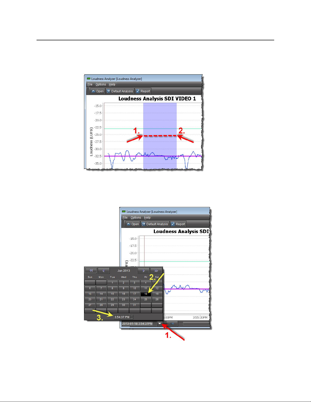
To zoom into Loudness Analyzer’s data plot
1. In Loudness Analyzer, do ONE of the following two sub-procedures:
a) On the data plot, use your mouse to click and hold on any point along the vertical line
marking the desired beginning time of your zoom.
47
Page 52
Using iControl Solo
Zooming into Loudness Analyzer’s Data Plot
b) Drag the mouse to any point along the vertical line marking the desired end time of
your zoom.
c) Release the mouse button.
OR,
a) On the bottom-left side of Loudness Analyzer, use the Start-time calendar to indicate
the exact beginning date and time of your zoom.
48
b) On the bottom-right side of Loudness Analyzer, use the End-time calendar to indicate
the exact end date and time of your zoom.
Page 53

iControl Solo
User Guide
Loudness Analyzer reloads the data stream using the new time range demarked by the
new start- and end-times.
2. Repeat step 1 if you must zoom into the data plot further.
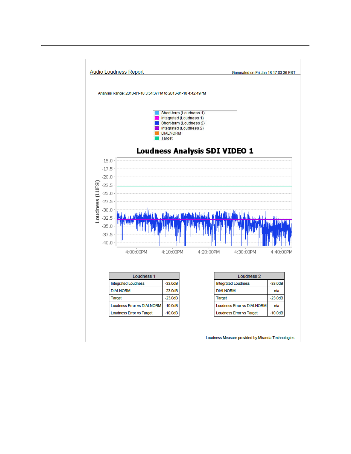
Generating a Loudness Analysis Report
Loudness Analyzer permits you to generate a report in PDF format. The report provides the
data currently displayed in Loudness Analyzer, including the chart at its current scaling
(zoom), as well as the parameters configured.
REQUIREMENTS
Make sure you meet the following conditions before beginning this procedure:
• You have opened a loudness data file in Loudness Analyzer (see page 44).
• You have adjusted the scaling of Loudness Analyzer’s data plot to the desired level
(see "Zooming into Loudness Analyzer’s Data Plot", on page 47).
• You have selected the plot series you would like to include in your report and selected
the desired analysis parameters (see "Configuring Loudness Analysis Parameters",
on page 45).
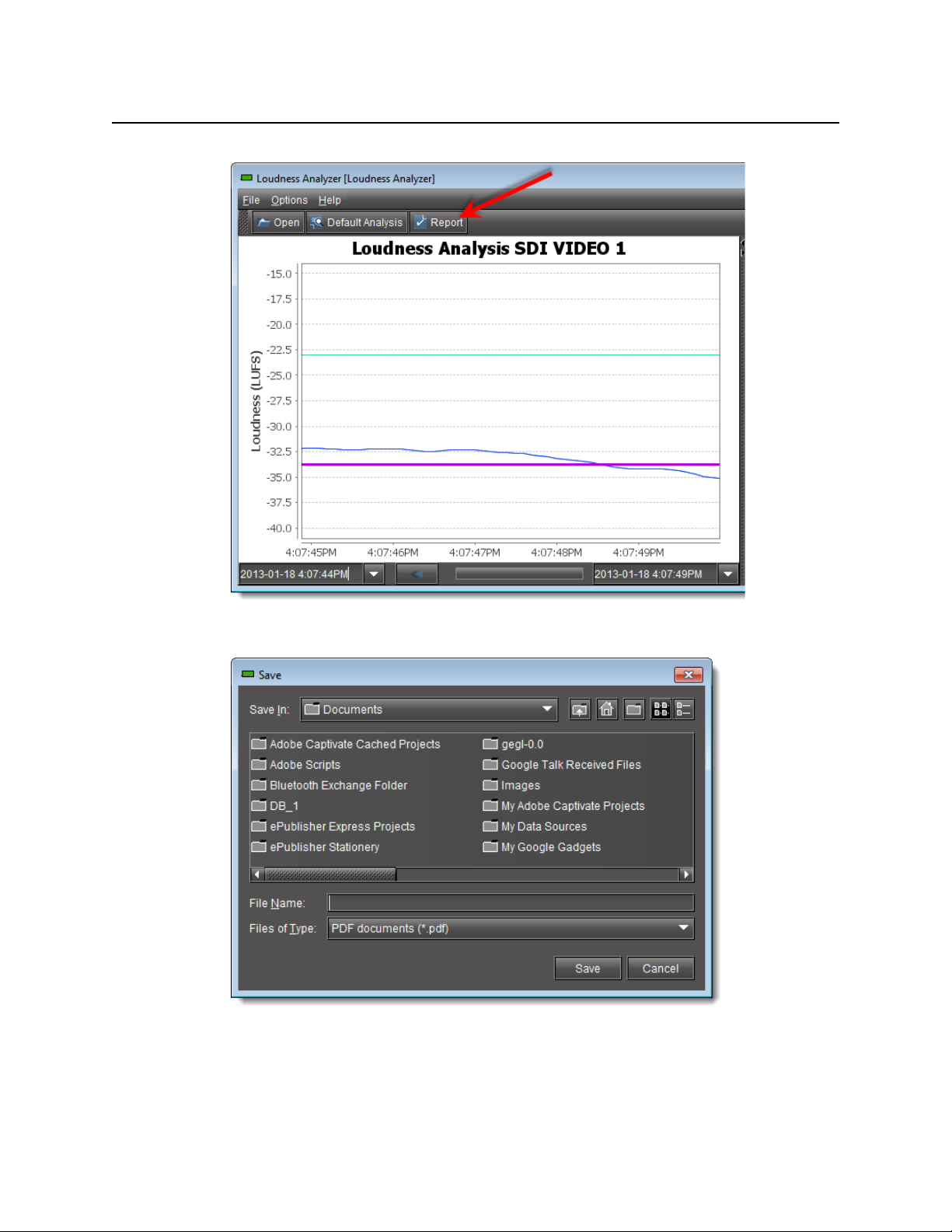
To generate a loudness analysis report
1. In Loudness Analyzer, click Report.
49
Page 54
Using iControl Solo
Generating a Loudness Analysis Report
The Save window appears.
2. Save the PDF file to a local directory.
The PDF file contains all of the information currently in view in Loudness Analyzer.
50
Page 55
iControl Solo
User Guide
Loudness analysis report (taken from the PDF output)
Working with Densité Upgrade Manager
From time to time, improvements or fixes may become available that can be applied to an
existing Densité card by upgrading its firmware and software. Firmware and software updates
are available as a bundled package. To determine if an update package is available for a
specific card, please contact Miranda Technical Support (see "Contact Us", on page 65).
51
Page 56
Using iControl Solo
Opening Densité Upgrade Manager
Opening Densité Upgrade Manager
REQUIREMENT
Before beginning this procedure, make sure the Densité frame housing the card whose
upgrade package would like to change is visible in the Densité Manager of iControl Solo
(see step 1 of "Adding Densité Communicator Services" on page 5).
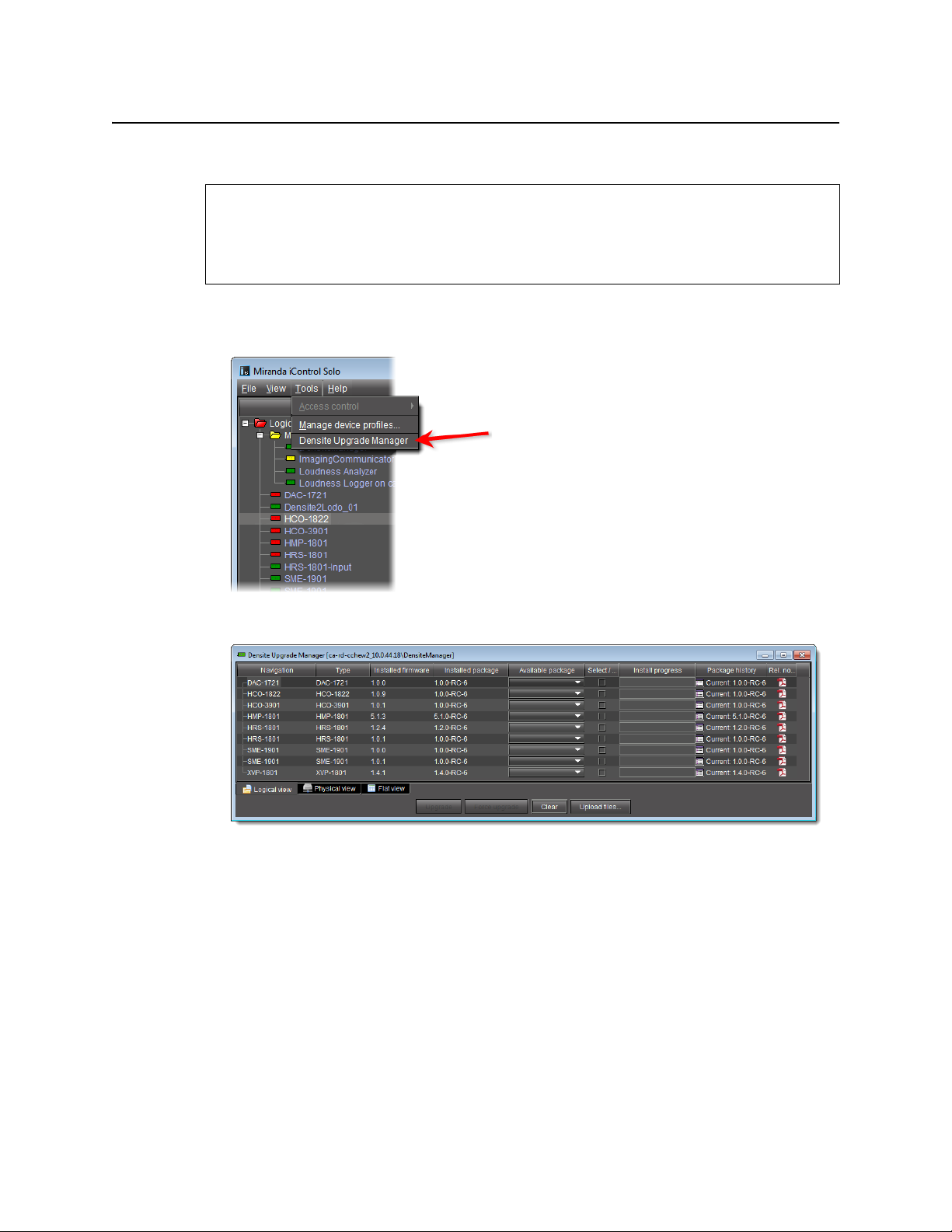
To open Densité Upgrade Manager
•In iCSolo, on the Tools menu, click Densité Upgrade Manager.
Densité Upgrade Manager appears.
Changing a Densité Card’s Installed Package
The package of a Densité card consists of a version of software and a version of firmware
bundled together. You can upgrade your card’s firmware and software simply by upgrading
the installed package. Use iControl Solo’s Densité Upgrade Manager to manage your card
packages and Densité card upgrades.
52
Page 57
IMPORTANT: System behavior
Regardless of whether your installed package is upgraded, downgraded or
rolled back, software always installs from a package stored on your local file
system. If you use the Upgrade button, firmware installs ONLY IF it has a different
version number (either newer or older) than the currently installed firmware.
If you would like to force your Densité card to install same-version firmware, use
the Force upgrade functionality (see page 55).
REQUIREMENTS
Make sure you meet the following conditions before beginning this procedure:
• You have opened Densité Upgrade Manager (see page 52).
• The Densité cards whose installed packages you would like to change are visible in
Densité Upgrade Manager.
• The package you would like to install on your Densité card has already been uploaded to
(see "Uploading a Densité Card Package", on page 59).
iControl Solo
User Guide
To change a Densité card’s installed package
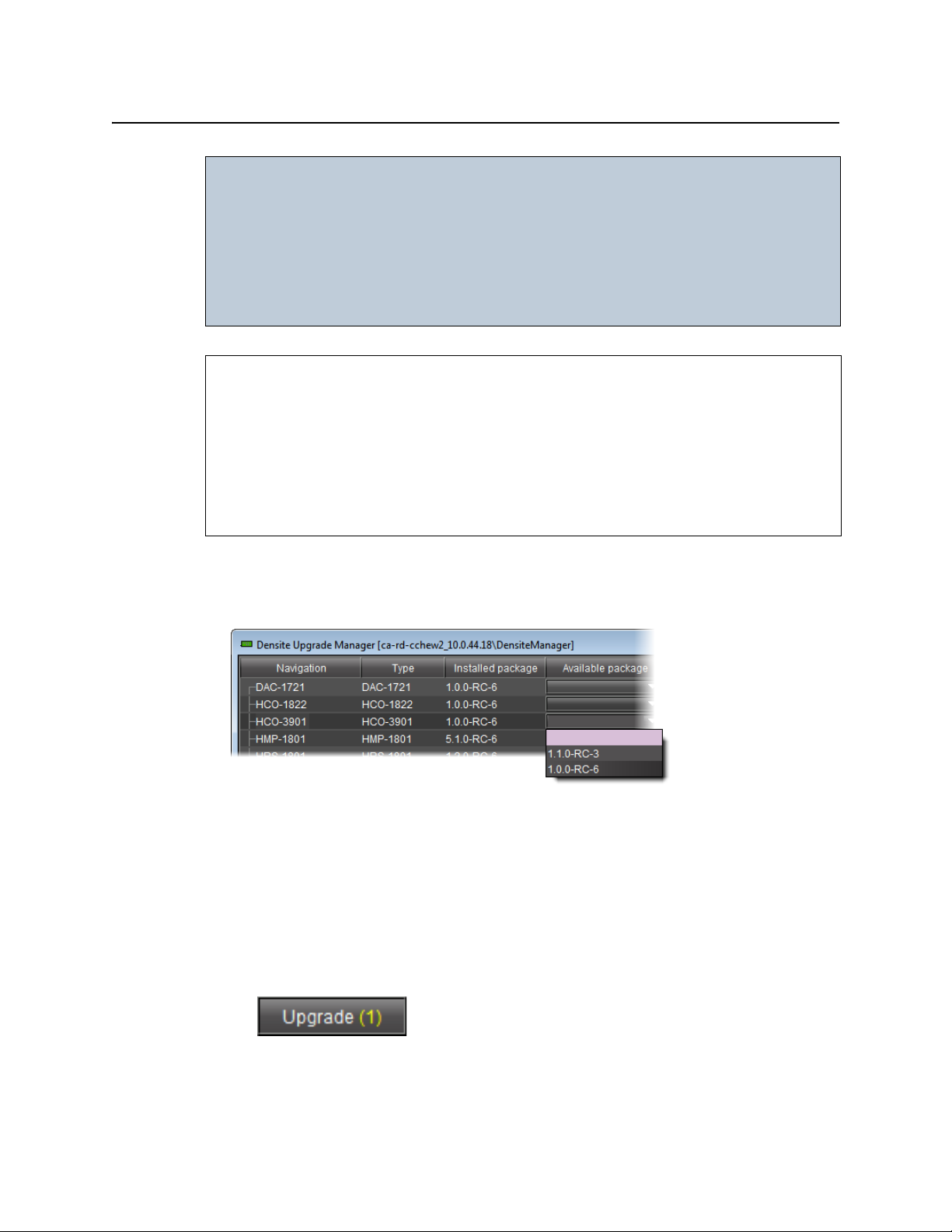
1. In Densité Upgrade Manager, verify if the package you would like to install on your
Densité card is available on the Application Server in the Available package column.
2. In the Available package column, in the row corresponding to the card to be upgraded or
downgraded, select the package you would like to use.
In the row corresponding to each Densité card you are upgrading or downgrading, the
following should occur:
•The Select/Bypass checkbox is selected.
•The Upgrade button bears the (N) suffix, where N indicates the number of cards
selected for package installation.
53
Page 58
Using iControl Solo
Changing a Densité Card’s Installed Package
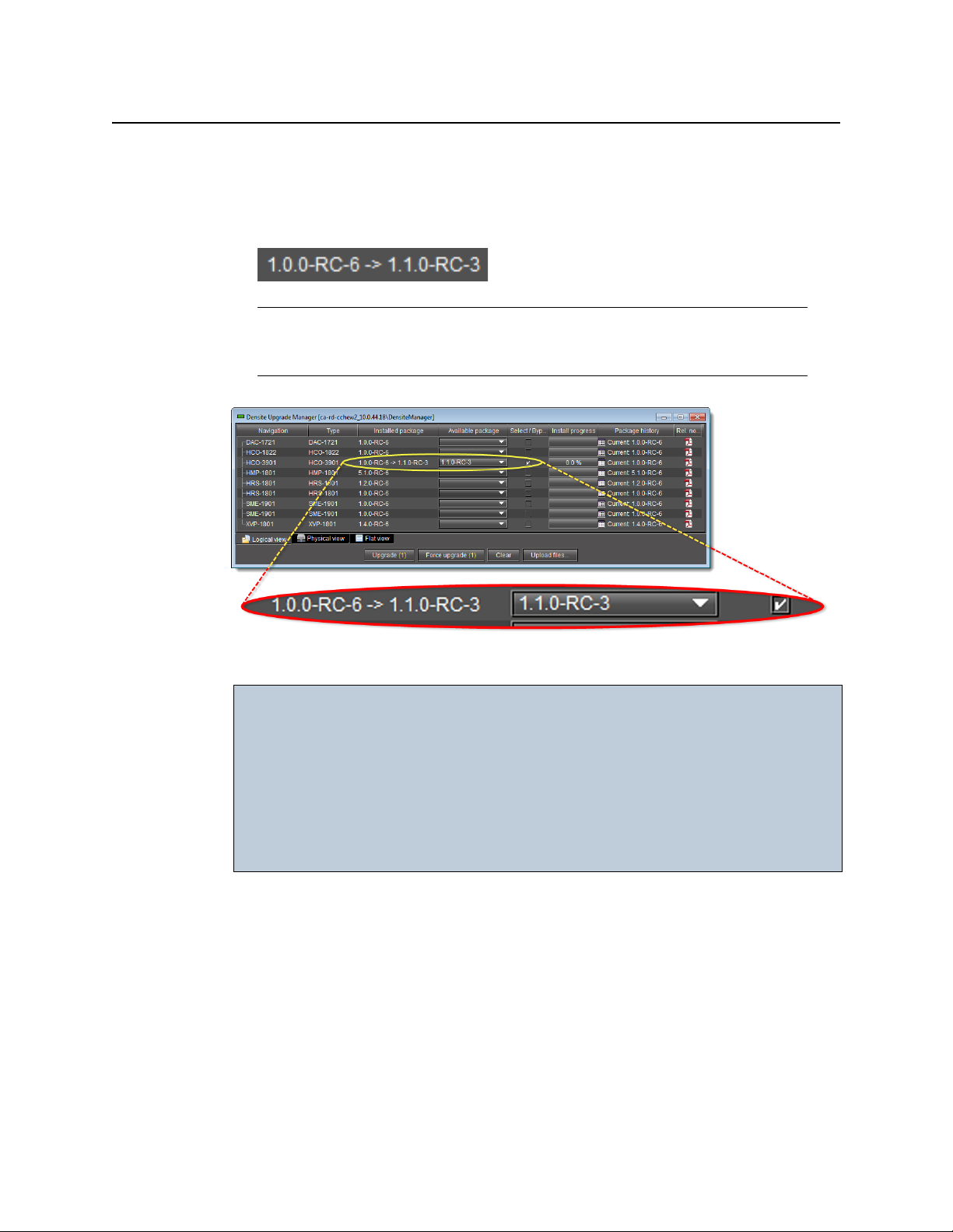
• The selected package appears in the Available package column.
• The upgrade/downgrade paths of firmware, software, and package are displayed
respectively in the Installed firmware, Installed software, and Installed package
columns.
Note: The paths for firmware and software are displayed only if you have first
manually made visible the Installed firmware and Installed software columns of
Densité Upgrade Manager (see page 60).
Selected package with package upgrade path displayed
IMPORTANT: In rare circumstances, you may have a Beta version of firmware installed on
your Densité card and may wish to upgrade to a full production version of
firmware bearing the same version number. In this situation, if you use the
Upgrade button, Densité Upgrade Manager will not install the firmware.
To force Densité Upgrade Manager to install firmware of the same-version
as the currently installed firmware, click Force upgrade instead of Upgrade.
(see "Forcing a Same-Version Firmware Installation onto a Densité Card",
on page 55).
3. Click Upgrade (or in the rare situation detailed above, click Force upgrade).
The Upgrade confirmation window appears.
4. Click Ye s .
During the upgrade, a progress bar appears in the Install progress column and the card
icon becomes yellow.
When the process is finished, the Upgrade Succeeded message appears.
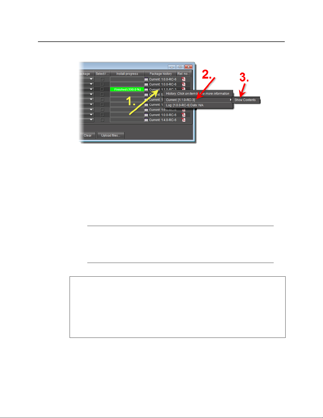
5. If you would like to view a log of this upgrade session, click the cell at the intersection of the
Package history column and the row corresponding to the Densité card whose installed
package you just changed.
54
Page 59
iControl Solo
User Guide
6. Point to Current, and then click Show Contents.
The last upgrade’s status (the status of the currently installed package) is displayed on a
per component basis.
Forcing a Same-Version Firmware Installation onto a Densité Card
Perform this procedure ONLY in the rare situation that the card you would like to upgrade
currently has a Beta version of firmware. If this is the case, using the Upgrade button will not
upgrade the firmware to the full production version of firmware bearing the same official
release number (even if Densité Upgrade Manager indicates both the package and software
versions have been upgraded). Only the Force upgrade button successfully installs sameversion firmware.
Note: After performing a forced upgrade of firmware, executing a rollback
operation will roll back the card to the pre-upgrade firmware even if the two versions
carry the same version number. In effect, after a forced upgrade, by selecting a
Rollback version (under Available package), you are in fact performing a forced
rollback operation.
REQUIREMENTS
Make sure you meet the following conditions before beginning this procedure:
• You have opened Densité Upgrade Manager (see page 52).
• The Densité cards whose firmware and software you would like to upgrade are visible in
Densité Upgrade Manager.
• The package you would like to use to upgrade your Densité card has already been
uploaded (see "Uploading a Densité Card Package", on page 59).
To force a same-version firmware installation onto a Densité card
1. In Densité Upgrade Manager, verify if the package you would like to install on your
Densité card is visible in the Available package column.
55
Page 60

Using iControl Solo
Forcing a Same-Version Firmware Installation onto a Densité Card
Note: Miranda recommends displaying the Installed firmware column of Densité
Upgrade Manager for this procedure. For steps on how to display this column,
see "Viewing a Densité Card’s Installed Firmware Version", on page 60.
2. In the Available package column, select the desired package.
3. In the Installed firmware column, take note of the upgrade path.
If the displayed upgrade path indicates that the card is not moving to a different firmware
version (for example, if the displayed upgrade path is
firmware you must use the Force upgrade functionality. Otherwise, you may use the
Upgrade functionality.
1
3.1.2‐ >3.1.2), then to override the
4. Click Force upgrade.
A confirmation message appears.
5. Click Continue.
1. The real-world situation in which you will find it necessary to override typical Upgrade button functionality (that
is, to force an upgrade of same-version firmware from a selected package) would be if your installed firmware is a
Beta version and the embedded firmware in the selected package is the production version of firmware bearing
the same release number.
56
Page 61

The upgrade proceeds.
When the upgrade operation is complete, a
progress column.
iControl Solo
User Guide
Finished message appears in the Install
Viewing Upgrade Logs
REQUIREMENT
Before beginning this procedure, make sure you have opened Densité Upgrade Manager
(see page 52).
To view upgrade logs
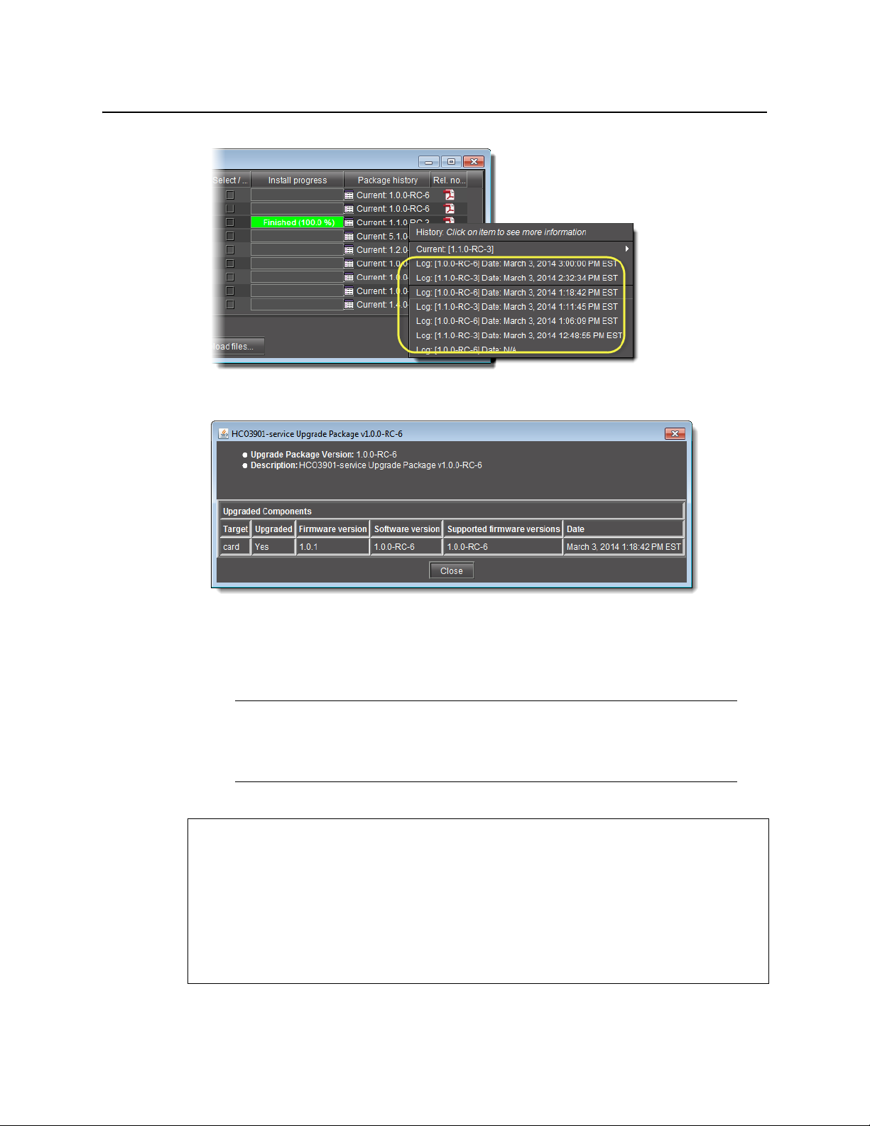
1. In Densité Upgrade Manager, in the row corresponding to the card whose upgrade
history you would like to view, click in the Package history column.
2. Click the upgrade log you wish to view.
57
Page 62
Using iControl Solo
Rolling Back a Card’s Installed Package to the Pre-Upgrade Version
The selected log is displayed.
Rolling Back a Card’s Installed Package to the Pre-Upgrade Version
Perform this procedure if, after installing a package on a Densité card, you decide to restore
both the firmware and software of the card to their respective pre-installation versions.
Note: In the case where you are rolling back a package installation resulting from a
Force upgrade operation, the rollback operation effectively becomes a Force rollback
operation. That is, even though the firmware currently installed and the firmware you
are rolling back to bear the same version number, the rollback will proceed.
REQUIREMENTS
Make sure you meet the following conditions before beginning this procedure:
• You have opened Densité Upgrade Manager (see page 52).
• The Densité cards whose firmware and software you would like to downgrade are visible
in Densité Upgrade Manager.
• The package you would like to use to downgrade your Densité card has already been
uploaded (see "Uploading a Densité Card Package", on page 59).
58
Page 63

iControl Solo
User Guide
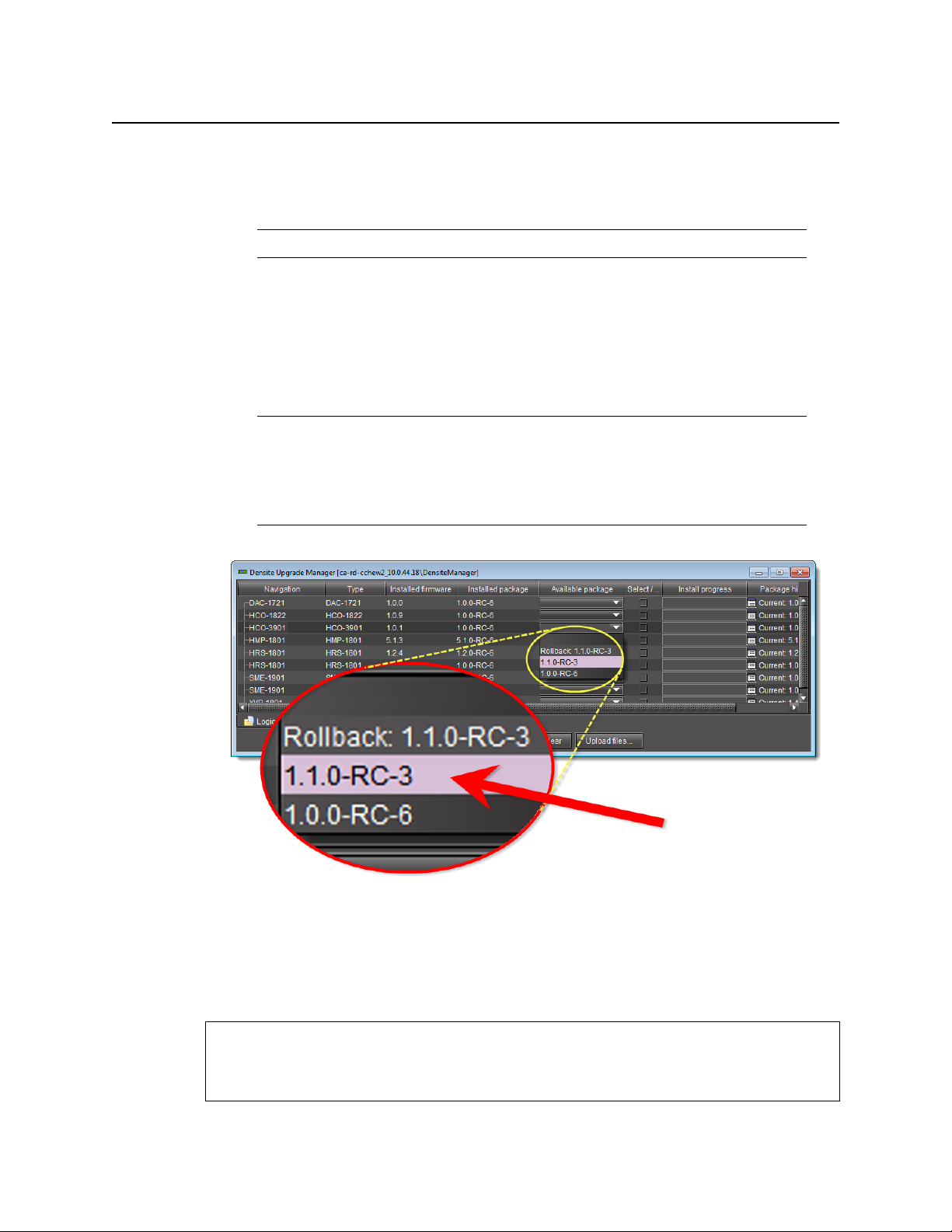
To roll back a Densité card’s installed package to the pre-upgrade version
1. In Densité Upgrade Manager, in the row corresponding to the card whose installed
package you would like to roll back, select Rollback <version #> in the Available package
column.
The Select/Bypass checkbox for that card is selected, indicating that this card will undergo
a change in its installed package, and the rollback path is indicated in the Installed
package column.
2. Click Upgrade.
The rollback operation begins. You can monitor the progress of the rollback with the
progress bar in the Install progress column.
When the rollback operation is complete, the Install progress column displays a success
message.
Uploading a Densité Card Package
REQUIREMENT
Before beginning this procedure, make sure you have access to the upgrade package file on
your local file system. If you do not have the correct upgrade package, contact Miranda
Technical Support (see "Contact Us", on page 65).
To upload an upgrade package
1. In Densité Upgrade Manager, click Upload files.
59
Page 64
Using iControl Solo
Viewing a Densité Card’s Installed Firmware Version
A file browsing window appears.
2. Navigate to the appropriate directory in your local file system, select the required upgrade
package file, and then click Open.
Note: You may select more than one package file to upload at a time.
A message window appears, prompting you to start the upload process.
3. Click Upload.
4. Click Close to close the window.
5. In the Upgrade package column of Densité Upgrade Manager, verify that the new
upgrade package is present.
Note: In order to see the newly uploaded package in the Available package
column, you must make sure you are reading from a row corresponding to a Densité
card compatible with the newly uploaded package firmware and software (i.e. If you
uploaded an XVP-3901 package, check the available packages in a row
corresponding to an XVP card.)
60
Viewing a Densité Card’s Installed Firmware Version
You may decide to make the installed firmware version of your Densité cards visible in Densité
Upgrade Manager. This may be desired, for example, if you would like to see more clearly if a
package upgrade resulted in an installation of its firmware as well.
REQUIREMENT
Before beginning this procedure, make sure you have opened Densité Upgrade Manager
(see page 52).
Page 65
iControl Solo
User Guide
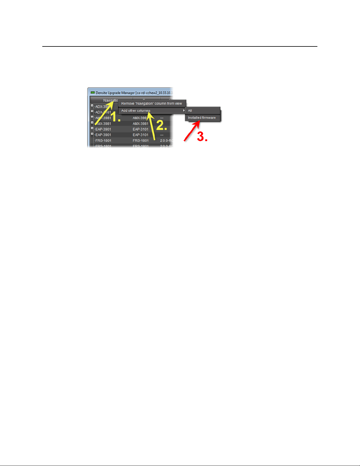
To view a card’s firmware version
1. In Densité Upgrade Manager, right-click anywhere in the header row, point to Add other
columns, and then select Installed firmware.
2. Perform the action of step 1 again, this time selecting whichever of Installed firmware or
Installed software you did not select before.
61
Page 66

Using iControl Solo
Viewing a Densité Card’s Installed Firmware Version
62
Page 67

This appendix provides instructions on installing the IC-USB device.
Key Concepts
IC-USB
The IC-USB device is a USB-to-RS-422 converter. It is used to establish communication
between your PC or laptop, and serial devices such as the Quartet 2 and Symphonie Miranda
Imaging Series housing frames.
IC-USB Driver
The IC-USB driver is installed automatically with the Miranda iControl Solo software. When you
connect the IC-USB device to your PC or laptop, Windows will automatically detect the new
hardware and associate it with the IC-USB driver.
Installing IC-USB
Detailed Directions
Connecting the IC-USB Device to a PC or Laptop
To connect the converter to your PC or laptop
1. Plug the Type A (flat) connector end of the USB cable into the USB port located in the back
of your PC.
2. Plug the Type B (square) end of the USB cable into the IC-USB device.
Connecting the IC-USB Device to a Miranda Quartet 2 Frame
To connect the converter to a Miranda Quartet 2 frame
1. Connect the IC-USB device’s DE-9 connector to the supplied RJ-45-to-DE-9 female adapter.
2. Connect one end of the supplied Ethernet cable to the RJ-45-to-DE-9 female adapter, and
the other end to one of the RJ-45 ports in the back of the Quartet 2 frame:
IC-USB connected to a Miranda Quartet 2 frame
Page 68
Installing IC-USB
Connecting the IC-USB Device to a Miranda Symphonie Frame
Connecting the IC-USB Device to a Miranda Symphonie Frame
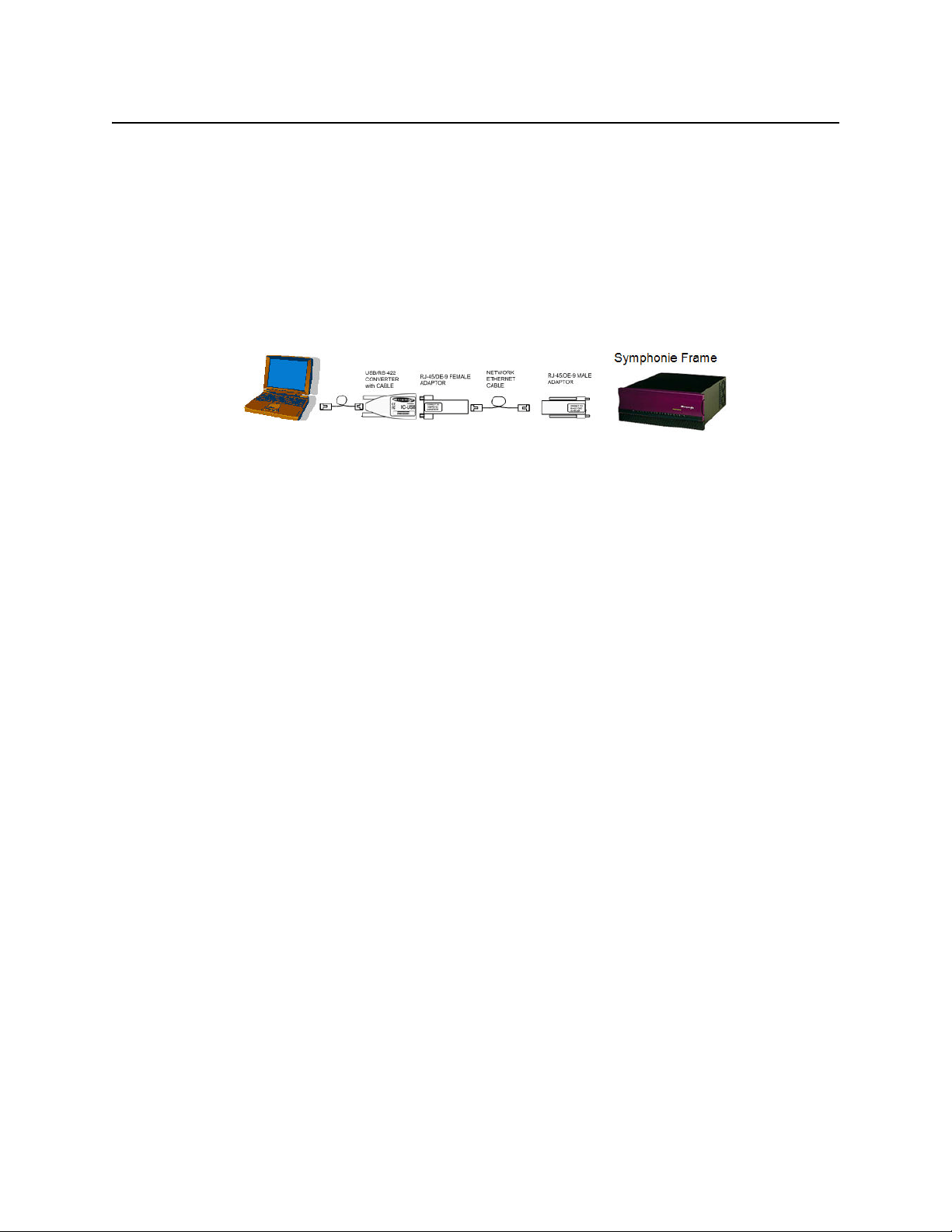
To connect the IC-USB to a Miranda Symphonie Frame
1. Connect IC-USB, RJ-45-to-DE-9 female adapter and Ethernet cable as described under
"Connecting the IC-USB Device to a Miranda Quartet 2 Frame", above.
2. Connect the RJ-45-to-DE-9 male adaptor to the Ethernet cable.
3. Connect the male adaptor to one of the RS-422 female DE-9 ports in the back of the
Symphonie frame:
IC-USB connected to a Miranda Symphonie frame
Determining the IC-USB COM Port Number
The IC-USB COM port number is required to configure the Miranda iControl Solo Imaging
Communicator service.
To determine the COM port number associated with IC-USB
1. On the Start menu, point to Programs, then to Inside Out Networks, and click Edgeport
Configuration Utility.
2. Expand the Edgeport 1i line item from the General Tab.
The COM port number is specified in brackets.
Installing a Single Imaging Frame
Ensure that the frame is properly terminated (refer to the Installation Guide for your Quartet 2
or Symphonie frame).
Installing Multiple Imaging Frames
A maximum of four Imaging frames (Quartet 2 and Symphonie) can be daisy-chained
together. Each individual frame in the daisy chain requires a different serial identification
assignment. The last frame in the chain must be terminated (refer to the Installation Guide for
your Quartet 2 or Symphonie frame).
64
Page 69

Miranda Technical Support
For technical assistance, please contact the Miranda Technical Support center nearest you:
Americas Asia
Office hours: 9:00 a.m. - 9:00 p.m. (EST) Office hours: 9:00 a.m. - 5:00 p.m. (GMT+8)
Telephone: 1-800-224-7882 Telephone: + 852 2539 6987
Fax: +1 514 335 1614 Fax: + 852 2539 0804
E-mail: support@miranda.com E-mail: asiatech@miranda.com
Europe, Middle East, Africa, UK China
Office hours: 9:00 a.m. - 6:00 p.m. (GMT) Telephone: + 86 10 5873 1814
Telephone: + 44 118 952 3444 E-mail: asiatech@miranda.com
Fax: + 44 118 952 3401
E-mail: eurotech@miranda.com
Contact Us
France EMERGENCY After Hours (Global)
Office hours: 9:00 a.m. - 5:00 p.m. (GMT + 1) Toll Free: 1-800-224-7882 (US and Canada)
Telephone: + 33 1 55 86 87 88 Telephone: +1 514 333 1772
Fax: + 33 1 55 86 00 29
E-mail:
Corporate Head Office
Miranda Technologies Partnership
3499 Douglas-B.-Floreani, St-Laurent, Québec, Canada H4S 2C6
Telephone: +514 333 1772
Fax: +514 333 9828
Web:
www.miranda.com
eurotech@miranda.com
Page 70

Contact Us
66
 Loading...