

Page 1
iControl Solo
User Gu ide
Part Number: M786-1600-324 11 July 2011
Page 2

1
Copyright Notice
Copyright © 2011 Miranda Technologies Inc. All rights reserved.
ATTENTION: Please read the following terms and conditions carefully. By using iControl documentation,
you agree to the following terms and conditions:
Miranda T echnologies Inc. her eby grants permission and license t o owners of iControl to use their pr oduct
manuals for their own internal business use. Manuals for Miranda Technologies Inc. products may not be
reproduced or transmitted in any form or by any means , electronic or mechanical, including photocopying
and recording, for any purpose unless specifically authorized in writing by Miranda Technologies Inc.
A Miranda T echnologies Inc. manual ma y have been r evised to r eflect changes made to the product during
its manufacturing life. Thus, differen t versions of a manual ma y exist for any giv en prod uct. Care should be
taken to ensure that one obtains the proper manual version for a specific product serial number.
Information in this document is subject to change without notice and does not represent a commitment
on the part of Miranda Technologies Inc.
Warranty Policies
Warranty information is available in the Support section of the Miranda Web site (www.miranda.com).
Title iControl Solo User Guide
Part Number M786-1600-324
Revision 11 July 2011 2:16 pm
ii
Page 3

Table of Contents
1 Introduction . . . . . . . . . . . . . . . . . . . . . . . . . . . . . . . . . . . . . . . . . . . . . . . . . . . . . . . . . 1
Overview. . . . . . . . . . . . . . . . . . . . . . . . . . . . . . . . . . . . . . . . . . . . . . . . . . . . . . . . . . . . . . . . . . . . . . . . . . . . . . . . . . . . . . . . . . . . . . . . . . . 1
Differences Between iControl Solo and the Standard iControl System. . . . . . . . . . . . . . . . . . . . . . . . . . . . . . . . . . . . . . . . . . . . . . . . 2
2 Getting Started with iControl Solo . . . . . . . . . . . . . . . . . . . . . . . . . . . . . . . . . . . . . . 3
Key Concepts . . . . . . . . . . . . . . . . . . . . . . . . . . . . . . . . . . . . . . . . . . . . . . . . . . . . . . . . . . . . . . . . . . . . . . . . . . . . . . . . . . . . . . . . . . . . . . . 3
Communicators . . . . . . . . . . . . . . . . . . . . . . . . . . . . . . . . . . . . . . . . . . . . . . . . . . . . . . . . . . . . . . . . . . . . . . . . . . . . . . . . . . . . . . . 3
Densité Manager . . . . . . . . . . . . . . . . . . . . . . . . . . . . . . . . . . . . . . . . . . . . . . . . . . . . . . . . . . . . . . . . . . . . . . . . . . . . . . . . . . . . . . 4
Detailed Directions . . . . . . . . . . . . . . . . . . . . . . . . . . . . . . . . . . . . . . . . . . . . . . . . . . . . . . . . . . . . . . . . . . . . . . . . . . . . . . . . . . . . . . . . . . .4
Connecting Densité and Imaging Series Housing Frames . . . . . . . . . . . . . . . . . . . . . . . . . . . . . . . . . . . . . . . . . . . . . . . . . . . . .5
Adding Densité Communicator Services . . . . . . . . . . . . . . . . . . . . . . . . . . . . . . . . . . . . . . . . . . . . . . . . . . . . . . . . . . . . . . . . . . .5
Configuring Imaging Communicator Services . . . . . . . . . . . . . . . . . . . . . . . . . . . . . . . . . . . . . . . . . . . . . . . . . . . . . . . . . . . . . . .7
3 Using iControl Solo. . . . . . . . . . . . . . . . . . . . . . . . . . . . . . . . . . . . . . . . . . . . . . . . . . . . 9
Key Concepts . . . . . . . . . . . . . . . . . . . . . . . . . . . . . . . . . . . . . . . . . . . . . . . . . . . . . . . . . . . . . . . . . . . . . . . . . . . . . . . . . . . . . . . . . . . . . . . 9
Navigator Window. . . . . . . . . . . . . . . . . . . . . . . . . . . . . . . . . . . . . . . . . . . . . . . . . . . . . . . . . . . . . . . . . . . . . . . . . . . . . . . . . . . . . 9
Control Panels and Device Parameters . . . . . . . . . . . . . . . . . . . . . . . . . . . . . . . . . . . . . . . . . . . . . . . . . . . . . . . . . . . . . . . . . . . 10
Control Panel Tabs. . . . . . . . . . . . . . . . . . . . . . . . . . . . . . . . . . . . . . . . . . . . . . . . . . . . . . . . . . . . . . . . . . . . . . . . . . . . . . . . . . . . 12
Info Control Panels. . . . . . . . . . . . . . . . . . . . . . . . . . . . . . . . . . . . . . . . . . . . . . . . . . . . . . . . . . . . . . . . . . . . . . . . . . . . . . . . . . . . 13
Devices Groups. . . . . . . . . . . . . . . . . . . . . . . . . . . . . . . . . . . . . . . . . . . . . . . . . . . . . . . . . . . . . . . . . . . . . . . . . . . . . . . . . . . . . . . 14
Views. . . . . . . . . . . . . . . . . . . . . . . . . . . . . . . . . . . . . . . . . . . . . . . . . . . . . . . . . . . . . . . . . . . . . . . . . . . . . . . . . . . . . . . . . . . . . . . 15
Alarm Status. . . . . . . . . . . . . . . . . . . . . . . . . . . . . . . . . . . . . . . . . . . . . . . . . . . . . . . . . . . . . . . . . . . . . . . . . . . . . . . . . . . . . . . . . 16
Reference Configuration. . . . . . . . . . . . . . . . . . . . . . . . . . . . . . . . . . . . . . . . . . . . . . . . . . . . . . . . . . . . . . . . . . . . . . . . . . . . . . . 17
Detailed Directions . . . . . . . . . . . . . . . . . . . . . . . . . . . . . . . . . . . . . . . . . . . . . . . . . . . . . . . . . . . . . . . . . . . . . . . . . . . . . . . . . . . . . . . . . 18
Opening iControl Solo . . . . . . . . . . . . . . . . . . . . . . . . . . . . . . . . . . . . . . . . . . . . . . . . . . . . . . . . . . . . . . . . . . . . . . . . . . . . . . . . . 18
Closing iControl Solo . . . . . . . . . . . . . . . . . . . . . . . . . . . . . . . . . . . . . . . . . . . . . . . . . . . . . . . . . . . . . . . . . . . . . . . . . . . . . . . . . . 18
Opening Control Panels . . . . . . . . . . . . . . . . . . . . . . . . . . . . . . . . . . . . . . . . . . . . . . . . . . . . . . . . . . . . . . . . . . . . . . . . . . . . . . . 18
Opening Info Control Panels . . . . . . . . . . . . . . . . . . . . . . . . . . . . . . . . . . . . . . . . . . . . . . . . . . . . . . . . . . . . . . . . . . . . . . . . . . . 18
Changing Device Information . . . . . . . . . . . . . . . . . . . . . . . . . . . . . . . . . . . . . . . . . . . . . . . . . . . . . . . . . . . . . . . . . . . . . . . . . . 19
Managing Device Groups . . . . . . . . . . . . . . . . . . . . . . . . . . . . . . . . . . . . . . . . . . . . . . . . . . . . . . . . . . . . . . . . . . . . . . . . . . . . . . 19
iii
Page 4

1
Adding Cards to the Reference Configuration . . . . . . . . . . . . . . . . . . . . . . . . . . . . . . . . . . . . . . . . . . . . . . . . . . . . . . . . . . . . . 20
Removing Cards from the Reference Configuration . . . . . . . . . . . . . . . . . . . . . . . . . . . . . . . . . . . . . . . . . . . . . . . . . . . . . . . . 21
Installing IC-USB. . . . . . . . . . . . . . . . . . . . . . . . . . . . . . . . . . . . . . . . . . . . . . . . . . . . . . . . 23
Key Concepts . . . . . . . . . . . . . . . . . . . . . . . . . . . . . . . . . . . . . . . . . . . . . . . . . . . . . . . . . . . . . . . . . . . . . . . . . . . . . . . . . . . . . . . . . . . . . . 23
IC-USB . . . . . . . . . . . . . . . . . . . . . . . . . . . . . . . . . . . . . . . . . . . . . . . . . . . . . . . . . . . . . . . . . . . . . . . . . . . . . . . . . . . . . . . . . . . . . . 23
IC-USB Driver . . . . . . . . . . . . . . . . . . . . . . . . . . . . . . . . . . . . . . . . . . . . . . . . . . . . . . . . . . . . . . . . . . . . . . . . . . . . . . . . . . . . . . . . 23
Detailed Directions . . . . . . . . . . . . . . . . . . . . . . . . . . . . . . . . . . . . . . . . . . . . . . . . . . . . . . . . . . . . . . . . . . . . . . . . . . . . . . . . . . . . . . . . . 23
Connecting the IC-USB Device to a PC or Laptop . . . . . . . . . . . . . . . . . . . . . . . . . . . . . . . . . . . . . . . . . . . . . . . . . . . . . . . . . . . 23
Connecting the IC-USB Device to a Miranda Quartet2 Frame . . . . . . . . . . . . . . . . . . . . . . . . . . . . . . . . . . . . . . . . . . . . . . . . 24
Connecting the IC-USB Device to a Miranda Symphonie Frame . . . . . . . . . . . . . . . . . . . . . . . . . . . . . . . . . . . . . . . . . . . . . . 24
Determining the IC-USB COM Port Number . . . . . . . . . . . . . . . . . . . . . . . . . . . . . . . . . . . . . . . . . . . . . . . . . . . . . . . . . . . . . . . 24
Installing a Single Imaging Frame . . . . . . . . . . . . . . . . . . . . . . . . . . . . . . . . . . . . . . . . . . . . . . . . . . . . . . . . . . . . . . . . . . . . . . 25
Installing Multiple Imaging Frames . . . . . . . . . . . . . . . . . . . . . . . . . . . . . . . . . . . . . . . . . . . . . . . . . . . . . . . . . . . . . . . . . . . . . 25
Contact Us! . . . . . . . . . . . . . . . . . . . . . . . . . . . . . . . . . . . . . . . . . . . . . . . . . . . . . . . . . . . . 27
iv
Page 5

Welcome to iControl Solo!
Overview
This guide describes how to configure and use iC ontrol Solo for contr olling and monitoring devices required
in the broadcast signal path for interfacing, routing and distribution. iControl Solo is designed and
produced by Miranda Technologies Inc.
Introduction
iControl Solo is a stand-alone PC-based control application which offers affordable control directly from a
desktop or laptop that has Windows7™ or Windows XP™ Professional. It provides easy list-based control
and configuration of up to 100 Densité Series and/or Imaging Series modules. Operators are provided with
quick access to devices and parameters for fast and easy control. More advanced control requirements
demanding simultaneous, multi-device monitoring and error logging , and a customized, highly graphical
user interface, can be met with the iControl Web and iControl PM applica tions. A USB-to-RS-422 adapter
(IC-USB) used to connect Imaging Series housing frames is sold separately.
In brief, iControl Solo offers the following key features and benefits:
• a Navigator window with different sorting options, similar to iControl Navigator,
• drivers for most Miranda Densité and Imaging devices,
• the ability to interface up to 100 devices,
• easy problem resolution using status indicators,
•ideal for set and forget operations.
Page 6

Introduction
1
Differences Between iControl Solo and the Standard iControl System
Differences Between iControl Solo and the Standard iControl System
iControl Solo does not:
•provide thumbnails,
• use a GSM (Global Status Manager) for central management of alarm conditions and error logging,
•support audio level meters (ALMs),
• allow simultaneous access to the same devices from an RCP-100 control panel,
• support Virtual Service Managers for configuring and controlling Miranda proc amp devices,
• support Router Manager for configuring and controlling routing switchers.
2
Page 7

Getting Started with iControl Solo
This section explains how to set up your iControl Solo system.
Summary
Key Concepts
Connecting Densité and Imaging Series Housing Frames
Adding Densité Communicator Services
Configuring Imaging Communicator Services
Key Concepts
Communicators
Communicators are software components that implement a specific protocol for controlling a family of
devices.
Communicators in iControl Solo are responsible for the discovery process whereby aPCor laptop detects
Miranda devices connected to its serial ports or on the LAN, and initiates services to control these devices.
A communicator is an application that handles the communications between yourPC or laptop and
Densité or Imaging series frames on the network. The two types of communicators (Imaging and Densité)
are configurable services in iControl Solo.
. . . . . . . . . . . . . . . . . . . . . . . . . . . . . . . . . . . . . . . . . . . . . . . . . . . . . . . . . . . . . . . . . . . . . . . . . . 3
. . . . . . . . . . . . . . . . . . . . . . . . . . . . . . . . . . . . . . 5
. . . . . . . . . . . . . . . . . . . . . . . . . . . . . . . . . . . . . . . . . . . . . . . . . . . . 5
. . . . . . . . . . . . . . . . . . . . . . . . . . . . . . . . . . . . . . . . . . . . . . . 7
Page 8

Getting Started with iControl Solo
2
Densité Manager
Imaging Communicators allow you to control signal processing and distribution performance modules
housed in Miranda Imaging series (Symphonie, Quartet2) frames. The Imaging series frames are
connected to yourPC or laptop via RS-422 serial ports.
Densité Communicators allow you to control interfacing and distribution modules housed in Miranda
Densité frames. A Densité frame is connected to the network via its Densité Controller Ethernet port.
T o be able to use a communica tor, the service must be configured. If the service is not configured, yo u will
not be able to control the devices even if they are connected. If the service is configured, but there are no
cards connected, only the service will be displayed in the Navigator window.
Densité Manager
The Densité Manager is a service that allows you to manage multiple Densité frames (using Densité
Communicators).
For the Densité Manager to discover cards and begin controlling services, you need to specify the
IPaddresses of the Densité frames that it will manage. Each frame ma y contain up to 20 devices. If y ou do
not add any addresses, or if you add an incorrect address, the Densité Manager will not discover any
frames.
Detailed Directions
To set up your iControl Solo system you will need to:
• connect the Densité and Imaging frames that house the cards you wish to control,
• configure Densité and Imaging services in iControl Solo.
4
Page 9
iControl Solo
User Guide
Connecting Densité and Imaging Series Housing Frames
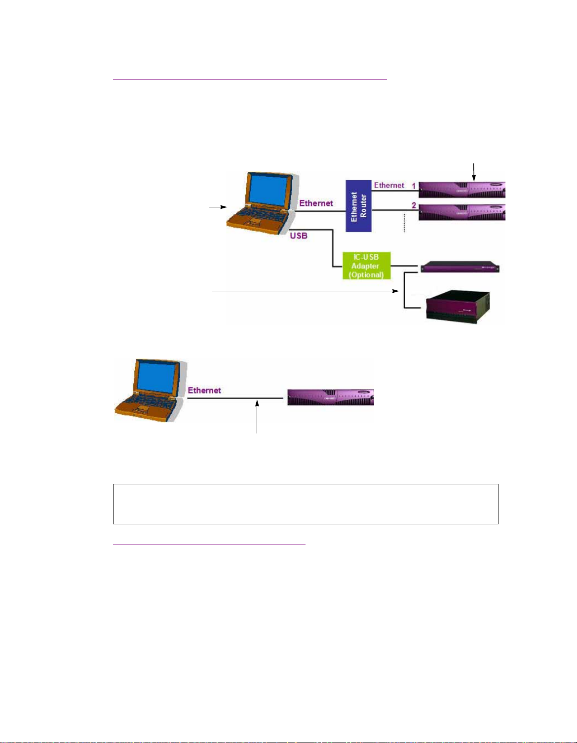
Densité frames can be connected over the network through an Ethernet router, or directly to yourPC or
laptop via a crossover cable. Imaging frames (Symphonie and Quartet2) are connected to yourPC or
laptop using either the IC-USB device, or an RS-232-to-RS-422 converter.
Up to 100 Densité cards
Customer-supplied PC or laptop that has
iControl Solo
Up to 4 daisy-chained Imaging frames
Connecting multiple Densité Series frames through a router, and up to 4 Imaging Series frames via IC-USB
Crossover Cable
Connecting a single Densité Series frame without a router
See also:
For more information about the IC-USB device, see"Installing IC-USB", on page23.
Adding Densité Communicator Services
To add a Densité Communicator service:
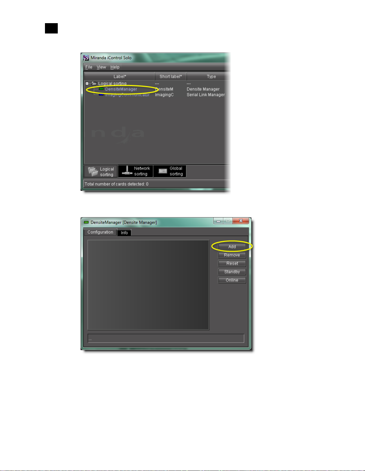
1. Open iControl Solo, and double-click DensiteManager in the logical navigator view.
5
Page 10
Getting Started with iControl Solo
2
Adding Densité Communicator Services
2. In DensiteManager, click Add.
3. In the Target Info rmation window, type the frame’s IPaddress and a descriptive name for the new
Densité Communicator service, and then click OK.
6
Page 11

iControl Solo
User Guide
The new Densité Communicator will be started and added to the list. iControl Solo will query the
corresponding Densité frame, and any devices (e.g .cards) it discov ers will be displayed in iC ontrol Solo’s
Navigator window.
Configuring Imaging Communicator Services
To configure the Imaging Communicator service:
1. Open iControl Solo, and double-click ImagingCommunicator in the logical navigator view.
2. In ImagingCommunicator, click Standby.
7
Page 12

Getting Started with iControl Solo
2
Configuring Imaging Communicator Services
3. In the COM Port list select the COM port you chose when you installed the IC-USB device
Note: COM port can only be selected in Standby mode.
4. Click Online to activate the selected port.
The Imaging Communicator service will be restarted and iControl Solo will query all Imaging Series
frames interfaced to your computer. An y devices (e.g. cards) housed in the frames will be displayed in
iControl Solo’s Navigator window.
8
Page 13

This section explains what can be accomplished with iControl Solo.
Summary
Using iControl Solo
Key Concepts
Detailed Directions
Key Concepts
Navigator Window
When you open iContr ol Solo, you see the menu bar, the hierarchical Na vigat or area, sorting tabs for three
different Navigator views, and a status bar.
. . . . . . . . . . . . . . . . . . . . . . . . . . . . . . . . . . . . . . . . . . . . . . . . . . . . . . . . . . . . . . . . . . . . . . . . . . 9
. . . . . . . . . . . . . . . . . . . . . . . . . . . . . . . . . . . . . . . . . . . . . . . . . . . . . . . . . . . . . . . . . . . . 18
Menu bar Hierarchical navigation area
Sorting tabsStatus bar
Page 14

Using iControl Solo
3
Control Panels and Device Parameters
The menu bar provides access to iControl Solo’s main features.
The status bar is where iControl Solo displays messages related to its current operations.
The sorting tabs are a way of filtering the information provided in the hierarchical Na vigator area t o include
all devices or a subset.
The hierarchical Navigator area is a representation of all the devices interfaced with iControl Solo.
You can use the plus and minus buttons in the hierarchy to navigate the hierarchical list views by
expanding and collapsing folders and groups (see "Managing Device Groups", on page19 for details).
The Navigator window shows the current status of every device and service within your iControl Solo
system. By default, the Navigator window displays the following information for each device:
Status icon Green (OK), yellow (warning), red (error), or grey (not connected).
See"Alarm Status", on page16.
Label The device type (by default) or a user-specified name. The text color reflects
the device configuration status.
See:
• "Changing Device Information", on page19
• "Reference Configuration", on page17
• "Adding Cards to the Reference Configuration", on page20
• "Remo ving Cards from the Reference Configuration", on page21
Short label Abbreviated 8-character label.
Source ID Name of the signal source.
Device type The device type.
Comments Optional; may be entered by the user.
Config s tatus Whether the device is or is not part of the Reference Configuration, also if
there is a mismatch between the actual and defined device.
See "Reference Configuration", on page17.
Frame Name of the frame housing the device (when applicable).
Slot Number of the slot where the device is located inside the frame (when
applicable).
Control Panels and Device Parameters
Most Miranda devices can be controlled using control panels. A control panel is a software interface that
lets you monitor and control various device parameters.
10
Page 15

iControl Solo
User Guide
Note: Miranda cards are shipped with Installation & Operation Guides that provide detailed
descriptions of their respective control panels, along with instructions on their use.
To access the control panel for a device, double-click the device in the Navigator window. Alternatively,
right-click the device name, and then click Show control panel on the shortcut menu.
The device name is displayed at the t op of its control panel, along with a dashboard containing one or more
icons representing the status of k ey device parameters. Error conditions are indicated by color and by a text
message that appears below the dashboard. If more than one error condition is present, hold the pointer
over an icon to continuously display its associat ed error message; otherwise the display cycles through all
reported errors.
Note: If the Control icon on the dashboard is yellow, this indicates that local card
control is active—the card is being controlled from a local hard war e contr ol panel. In
such a case, any changes made using the iContr ol Solo interface will have no effect on
the card.
11
Page 16

Using iControl Solo
3
Control Panel Tabs
When control panels are open their names are added to the View menu. To bring a specific panel to the
foreground, click its name on the View menu. To close all open panels at once, click Close all control
panels.
12
Control Panel Tabs
Note: For more information on a control panel, please refer to the Installation&Operation
Guide for the corresponding device.
The table below lists common contr ol panel tabs and their typical purposes:
Tab Description
Input Allows input selection, second input operation mode selection, and control of the
deglitcher and freeze functions.
Video Processing Contains color-correction parameters that apply to the input signal.
Video Output Allows control ov er several aspects of the high definition and standard definition video
output: aspect ratio conversion, timing control, image quality processing, metadata
insertion.
Page 17

iControl Solo
User Guide
(Continued)
Tab Description
Audio Processing Provides audio processing and delay parameters for the embedded or discrete audio input
channels. These parameters affect both the output audio channels (embedded and AES)
and the audio channels sent to other companion cards.
Audio Output Provides extended audio processing for the 16 audio channels embedded in the HD/SD
outputs, including audio channels mixing and audio embedding mode.
Timing Provides access to timing adjustments which affect the signal outputs.
Factory/Presets Allows user and device profile management, and restoring of a device’s factory default
configuration.
Options Describes available options for the device, and provides information on how to enable or
disable them.
Alarm Config. Opens a separate window where alarm status can be monitored and configured.
Info Allows viewing and modifying information about a device (e.g. labels, source ID,
comments) to help identifying a specific device in a comple x setup.
Info Control Panels
The Info control panel is available for all device types. The Info panel includes device identification
information such as a label, a short label, the device type, comments, source ID, config status, frame, and
slot. You can display the Info panel from the device control panel, or you can right-click a device in the
Navigator window and then click Show info control panel from the shortcut menu.
From the Info panel, you can change the name of the selected device and type comments. By default , the
device name takes the type identification; however, you will find it helpful to rename devices using
13
Page 18

Using iControl Solo
3
Devices Groups
meaningful names. Once you change the device name in the control panel, the new name will be displayed
in the Navigator window, making the device easier to locate.
14
Example of an Info control panel for a specific device
Devices Groups
iControl Solo allows you to organize devices into logical groups, making them easier to locate and to
manage. A device group is a folder into which you drag selected devices. You can create as many device
groups and subgroups as you want.
When you create a device group, you automatically cr eate a virtual alarm that displays the over all status of
the member devices. The color of the device group’s folder icon will change when one or more of its
members displays an error or warning status. F or example , if one member device changes status as a result
Page 19

iControl Solo
User Guide
of a critical error, then the group’s folder icon will turn red. If no devices are assigned to a group, its folder
icon will be white.
New device group folder (circled)
Note: Device groups can only be created in (and are only visible in) iControl Solo’s Logical sort
mode.
Views
Sorting allows you to determine the way in which devices will be arranged for display in iControl Solo’s
Navigator window.
15
Page 20

Using iControl Solo
3
Alarm Status
Three views are available by clicking tabs at the bottom of the Navigator window.
Navigator tabs (circled)
• Logical view displays all active services and devices interfaced with iControl Solo. The devices and
services may be organized into groups. Groups and their contents are arranged in alphabetical order.
Ungrouped items are displa y ed at the end of the list. Empty slots are not shown, unless they ar e in the
Reference Configuration (see "Reference Configuration", on page17).
• Physical view arranges the devices relative to their physical connections and network location. All
frame slots are shown. Empty slots show up as “Empty,” unless the card i s designated as “In Ref.
Configuration,” in which case it will show up as before, but with the description “missing from slot.”
Devices are sorted by the name you typed when you added a Densité Communicator service, and by the
number of the serial port where an Imaging frame is connected.
• Flat view shows all devices in alphabetical order without any grouping.
Alarm Status
The current status of an alarm determines the color of any on-scr een object associated with that alarm: the
LED-like icon to the left of a device or service label, an enclosing folder, etc. Each possible alarm status is
represented by a color. Alarm statuses are dynamically updated.
1
iControl Solo implements an industry standard
describes the color scheme used by iControl Solo to display alarm statuses, and how they map to the
ITU-TX.733 Recommendation:
1. Default alarm severities in iControl Solo are compliant with the intent of ITU-T Recommendation X.733, Information
T e chnology – Open Systems Interconnection – Systems Management – Part 4: Alarm Reporting Function
color code definition for all alarms. The following table
16
Page 21

iControl Solo
User Guide
Color Status ITU-T X.733 Description
White Pending — Alarm exists but has not yet been reported. iControl Solo is waiting for the
hardware or driver to update the alarm. White is the default status for a
new alarm, before its current status is known. Th is status should be
replaced very quickly, though it might persist as the result of a slow
network connection. If a service is stopped, then all alarms originating
from this service will revert to pending status.
Green Normal Cleared The device, service, or signal is operating within allowable parameters.
Yellow Minor Minor/Warning Warning that an err or of low importance has occurred.
Orange Major Major Warning that an error of intermediate importance has occurred.
Red Critical Critical Warning that an error of critical importance has occurred.
Gray Unknown Indeterminate Failure to get the status of an alarm provider, even though the source
device has been detected. This could happen, for example, as the r esult of
(1) a lost network connection, or (2) a loss of signal that would trigger a
critical alarm for signal presence but leave all other related alarms in an
unknown status (e.g. the fr eeze or black sta tus is unknown if a signal is not
present).
Blue Non-
existent
Black Disabled Not supported Alarm exists but has been disabled at the source. Some devices can have
— A pseudo-status representing an alarm that has been removed (or was
never added). If an alarm provider is removed—for e xample, if a card is
removed from a frame—the virtual alarm will be unable to detect an
alarm status, and will therefore report the “non-existent” status as blue.
certain alarms disabled on the hardware itself, resulting in these alarms
appearing black.
Reference Configuration
The reference configuration is a feature of iC ontr ol Solo that allo ws you to keep track of important cards, or
groups of cards. If a card is removed from a slot, the default behavior in iControl Solo is for the card to
disappear from the list in the Logical and Global views. In the Network view, the device name is replaced
by the slot number followed by the indication
When you to designate a card as part of the refer ence configuration, then the name of the car d and the slot
number it occupies are retained. If the card is removed, its label will be visible as before, but with the
description
Missing from slot appended.
Empty.
17
Page 22

Using iControl Solo
3
Detailed Directions
Detailed Directions
Opening iControl Solo
To open iControl Solo:
• Use the iControl Solo shortcut on your desktop.
iControl Solo Navigator window appears.
Closing iControl Solo
To close iControl Solo:
•Do one of the following:
• Close all iControl Solo windows,
OR,
•On Navigator’s File menu, click Quit.
All changes are automatically saved.
Opening Control Panels
To open the control panel for a device:
• In the Navigator window, right-click the device, and then click Show control panel on the shortcut
menu. Alternatively, double-click the device.
The device’s control panel appears.
Opening Info Control Panels
To access the Info control panel for a device:
1. In the Navigator window, double-click the device.
The device control panel appears.
2. Do one of the following:
• Select the Info tab,
18
OR,
• In the Navigator window, right-click the device, and then click Show info control panel on the
shortcut menu.
Page 23

iControl Solo
User Guide
Changing Device Information
Some device information can be customized from the device’s Info control panel. Changes made in the
control panel are immediately applied to the device.
• The device name appears in the Label box.
• You can modify the sourceID and add comments in the corresponding boxes.
Renaming Devices
To rename a device:
1. Open the Info window for the device you wish to rename (see "Opening Info Control Panels", on
page18).
2. Type the new name in the Label box.
The changes are immediately applied.
Managing Device Groups
With iControl Solo, you can create as many device groups as necessary for your system, and then place the
various devices into the appropriate groups. A device can only be a member of one group.
Creating Groups
To create a group:
1. In the Navigator window, click Logical view.
2. Right-click the location for the new group (the root folder, or another folder within the hierarchical
structure) and then click Add Group on the shortcut menu.
The Group name window appears.
3. Type a name for the group (e.g. “satellite” or “remote”), and then click Create Group.
The group appears as a new folder in the chosen location.
19
Page 24

Using iControl Solo
3
Adding Cards to the Reference Configuration
Moving Groups
To move a group:
1. In the Navigator window, right-click the group you wish to move, and then click Cut on the shortcut
menu.
2. Right-click the destination folder, and then click Paste on the shortcut menu.
The group appears as a new folder in the chosen location.
Renaming Groups
To rename a group:
1. In the Navigator window, select the group folder you wish to rename.
2. Right-click the group folder and then click Rename group.
The Folder Name window appears.
Folder Name window
3. Type a new name for the group, and then click Rename gr oup .
The new group name appears for the chosen folder.
Removing Groups
To remove a group:
1. In the Navigator window, expand the group folder you wish to remove.
2. Remove all devices from the group folder b y dragging them to another folder or to the root of the folder
structure (only empty groups can be removed).
3. Right-click the empty group folder, and then click Remove group on the shortcut menu.
4. When prompted to confirm the removal, click Yes.
The group no longer appears in the Navigator window.
Adding Cards to the Reference Configuration
The reference configuration (see page17) is a way to keep track of cards or groups of cards important to
your setup.
20
Page 25

iControl Solo
User Guide
To add a card to the reference configuration:
• In the Navigator window, right-click the card you wish to add, and then click Add to reference
configuration on the shortcut menu.
The phrase
In Ref. Configuration appears in the Config status column.
Note: If this card is physically r emoved from its slot , the card name remains in the Label column,
along with the phrase
Missing from slot.
Removing Cards from the Reference Configuration
To remove a card from a reference configuration:
• In the Navigator window, right-click the card you wish to remove, and then click Remove from
reference configuration.
The phrase
Not In Ref. Configuration appears in the Config Status column.
21
Page 26

Using iControl Solo
3
Removing Cards from the Reference Configuration
22
Page 27

This appendix provides instructions on installing the IC-USB device.
Key Concepts
IC-USB
Installing IC-USB
The IC-USB device is a USB-to-RS-422 converter. It is used to establish communication between your PC or
laptop, and serial devices such as the Quartet2 and Symphonie Miranda Imaging Series housing frames.
IC-USB Driver
The IC-USB driver is installed automatically with the Miranda iControl Solo software. When you connect
the IC-USB device to your PC or laptop, W indows will automatically detect the new hardwar e and associate
it with the IC-USB driver.
Detailed Directions
Connecting the IC-USB Device to a PC or Laptop
To connect the converter to your PC or laptop:
1. Plug the TypeA (flat) connector end of the USB cable into the USB port located in the back of your PC.
Page 28

Installing IC-USB
Connecting the IC-USB Device to a Miranda Quartet2 Frame
2. Plug the TypeB (square) end of the USB cable into the IC-USB device.
Connecting the IC-USB Device to a Miranda Quartet2 Frame
To connect the converter to a Miranda Quartet2 frame:
1. Connect the IC-USB device’s DE-9 connector to the supplied RJ-45-to-DE-9 female adapter.
2. Connect one end of the supplied Ethernet cable to the RJ-45-to-DE-9 female adapt er , and the other end
to one of the RJ-45 ports in the back of the Quartet2 frame:
IC-USB connected to a Miranda Quartet2 frame
Connecting the IC-USB Device to a Miranda Symphonie Frame
To connect the IC-USB to a Miranda Symphonie Frame:
1. Connect IC-USB, RJ-45-to-DE-9 female adapter and E thernet cable as described under "C onnecting the
IC-USB Device to a Miranda Quartet2 Frame", above.
2. Connect the RJ-45-to-DE-9 male adaptor to the Ethernet cable.
3. Connect the male adaptor to one of the RS-422 female DE-9 ports in the back of the Symphonie frame:
IC-USB connected to a Miranda Symphonie frame
Determining the IC-USB COM Port Number
The IC-USB COM port number is required to configure the Miranda iControl Solo Imaging Communicator
service.
24
Page 29

iControl Solo
User Guide
To determine the COM port number associated with IC-USB:
1. On the Start menu, point to Programs, then to Inside Out Networks, and click Edgeport
Configuration Utility.
2. Expand the Edgeport1i line item from the General Tab.
The COM port number is specified in brackets.
Installing a Single Imaging Frame
Ensure that the frame is properly terminated (refer to the Installation Guide for your Quartet2 or
Symphonie frame).
Installing Multiple Imaging Frames
A maximum of 4 Imaging frames (Quartet2 and Symphonie) can be daisy-chained together. Each
individual frame in the daisy chain requires a different serial identification assignment. The last frame in
the chain must be terminated (refer to the Installation Guide for your Quartet2 or Symphonie frame).
25
Page 30

Installing IC-USB
Installing Multiple Imaging Frames
26
Page 31

Contact Us!
Miranda Technical Support
For technical assistance, please contact the Miranda Technical Support center nearest you:
Americas Asia
Office hours: 9:00a.m. - 9:00 p.m. (EST) Office hours: 9:00 a.m. - 5:00 p.m. (GMT+8)
Telephone: + 1-800-224-7882 Telephone: + 852-2539-6987
Fax: + 1-514-335-1614 Fax: + 852-2539-0804
E-mail: support@miranda.com E-mail: asiatech@miranda.com
Europe, Middle-East, Africa, UK China
Office hours: 9:00 a.m. - 6:00 p.m. (GMT) Telephone: + 86-10-5873-1814
Telephone: + 44 (0) 1491 820222 E-mail: asiatech@miranda.com
Fax: + 44 (0) 1491 820002
E-mail: eurotech@miranda.com
France EMERGENCY After Hours (Global)
Office hours: 9:00 a.m. - 5:00 p.m. (GMT + 1) Toll Free: 1-800-224-7882 (US and Canada)
Telephone: + 33 1 55 86 87 88 Telephone: +1-514-333-1772
Fax: + 33 1 55 86 00 29
E-mail:
eurotech@miranda.com
Corporate Head Office
Miranda Technologies Inc.
3499 Douglas-B.-Floreani, St-Laurent, Quebec, Canada H4S 2C6
Telephone: 514-333-1772
Fax: 514-333-9828
Web:
http://www.miranda.com
 Loading...